dissolved gas analysis - erpcerpc.gov.in/wp-content/uploads/2017/04/presentation_part_2.pdf · •...
TRANSCRIPT

Dissolved Gas Analysis
The Health Indicator for Oil Immersed Transformers
By RAJARSHI GHOSH 7th April 2017

What is DGA • It is the most effective tool for advanced
detection of almost all types of incipient fault inside an oil filled transformer.
• In a live transformer, Gases in oil always result from the decomposition of electrical insulation materials (oil or paper), as a result of faults or chemical reaction in the equipment.
• Different gases are generated at different situations and a particular fault can be detected by analysing the fault gases dissolved in the oil.

Why DGA is Essential • The most reliable and proactive method for
identification of fault inside a transformer at an early stage of development.
• Used world wide since 1960s.
• To reduce risk to the unit – Plant outage
• To reduce risk to the system it is connected - Interruptions / shutdown
• To reduce risk to the company – Loss of property / brand name
• To reduce risk to the personnel – Injury / Loss of human life (internal / external)
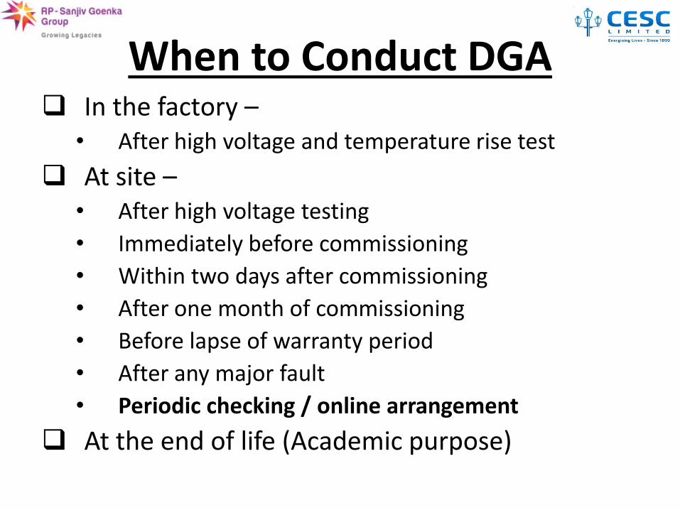
When to Conduct DGA In the factory –
• After high voltage and temperature rise test
At site – • After high voltage testing
• Immediately before commissioning
• Within two days after commissioning
• After one month of commissioning
• Before lapse of warranty period
• After any major fault
• Periodic checking / online arrangement
At the end of life (Academic purpose)
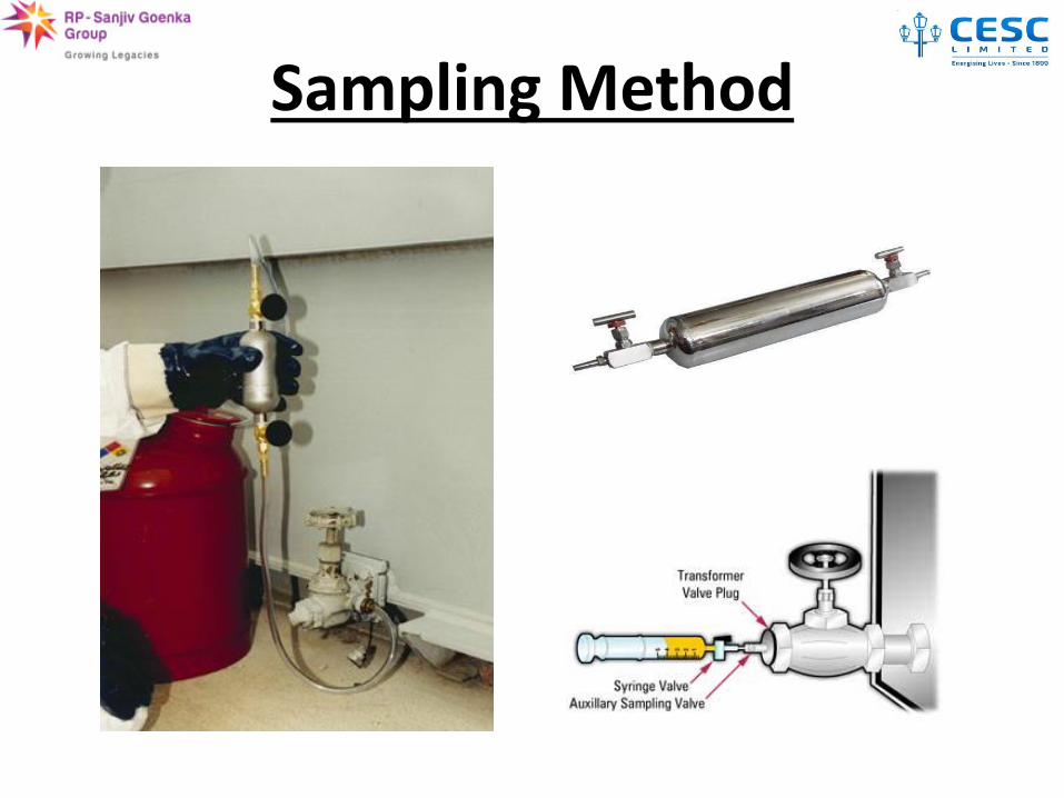
Sampling Method

Gas Extraction

DGA Process

Gas Analyser

Chromatogram


Interpretation Techniques


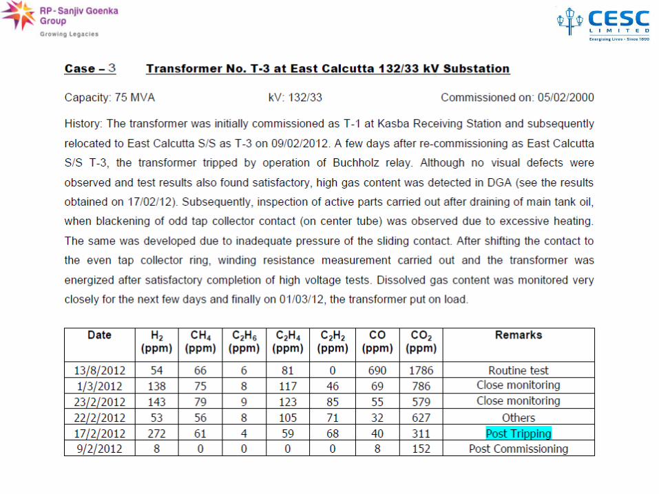
DGA Case Studies


Thank You
We will now analyse the Questions, still remained Dissolved in your minds

Asia Institute of Power Management
Communication in Power Utilities
April 2017

Electricity

Challenges to a Power Utility

Solution
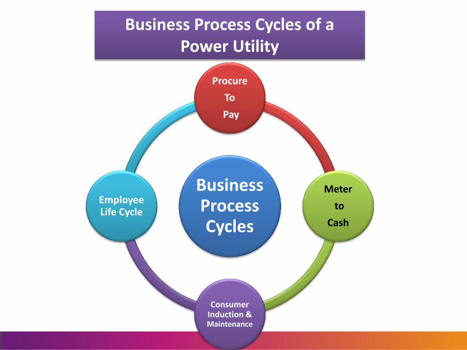
Business Process Cycles
Procure
To
Pay
Meter
to
Cash
Consumer Induction & Maintenance
Employee Life Cycle
Business Process Cycles of a Power Utility

Microwave
PLC
PLCC
OFC
Voice
VHF
GSM/GPRS
MPLS-VPN
Wire-line Wireless
Communication Systems
RF Mesh
Ap
plic
atio
ns
IT
OT

Wire-line Media
PLC
• Good solution for applications with low bandwidth requirement
• Not preferable due to reliability based on overhead transmission cables
PLCC
• Not considered in applications of Power Utilities
OFC
• Most reliable and available means of Wire-line Communication Solutions
• High Bandwidth can support any application
MPLS-VPN
• Service Provider dependent
• Can be integrated over long distances

Wireless Media
VHF
• Most popular method of Communication in Power Utilities
• Used for Relaying Alarm Reception in Substations
GSM/GPRS/3G/4G
• Available option for Last-mile Communication Solutions in AMR and DA
• Low Reliability
• Service Provider Dependent
RF Mesh
• Emerging Technology among Power Utilities around the World
• Considered for Street Lighting/Switching, AMI and DA
• Availability is based on Frequency Band used
Microwave
• Regulatory Compliances involved
• Reliability low due to Interference
• Limited Availability of Frequency Spectrum for Power Utilities

Communication in IT Network

Switch
MAIL (2 Nos.) IMSVA
(2 Nos.)
WEB / Ext. DNS SERVER (2 Nos.)
DMZ
Server Firewall (FWSM)
Storage Tek SL 500
(Tape Library)
SUN STORAGE TEK
6580 (SAN Storage)
Brocade 5000 SAN Switch
APPLICATION SERVER ZONE AND DATABASE ZONE
Firewall - Primary Firewall - Backup
SAN ZONE Altiris
DB DHCP/ DNS/
Proxy (2 Nos.)
Linux Infra
LMS
IWSVA (3 Nos.)
NAGIOS/ MRTG/WUG
SEP ALTIRIS
SERVER 1 SERVER 2
Switch
Switch
CISCO 2960G
CISCO 2960G
CISCO 2960G
Intranet Windows
Infra
CISCO 2960G
ISP2
Server Firewall (FWSM)
Network Architecture at Data Center
ISP1
Layer 3 Switch - Primary Layer 3 Switch - Backup

SUN E2900
SUN StorageTek 6130
JBOD NETWORK Supervisor PC
L2 Switch
L2
Switch
L2 Switch
Cash Office Billing Server at Datacenter
Network Infrastructure for Billing and Treasury Management
L2 Switch
L2 Switch
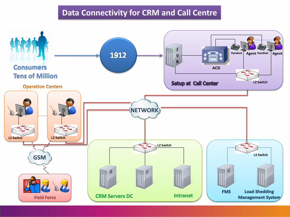
NETWORK
GSM
L2 Switch L2 Switch
L2 Switch
Agent Handset I
V
R
ACD
Agent Handset
Data Connectivity for CRM and Call Centre
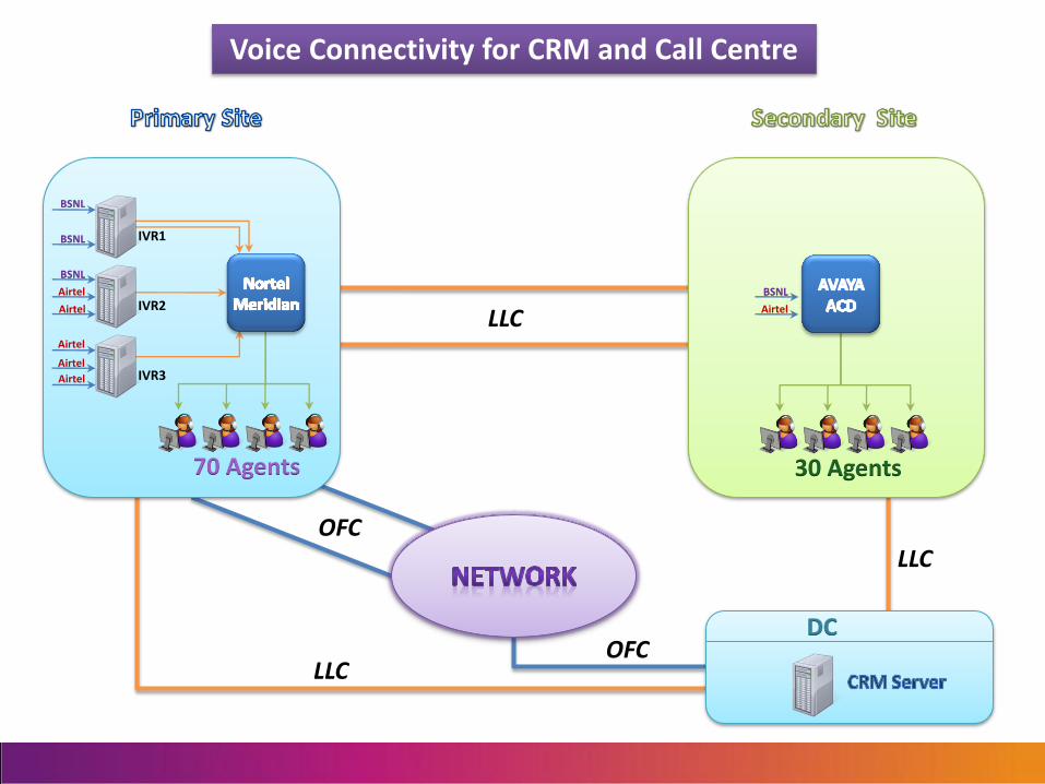
BSNL
BSNL
BSNL
Airtel
Airtel
Airtel
70 Agents 30 Agents
OFC
IVR1
IVR2
IVR3
OFC
Airtel
Airtel
BSNL
Airtel LLC
LLC
LLC
Voice Connectivity for CRM and Call Centre
Communication in OT Network

FOX515T
FM-FAN
MM-1
11
CM-8xRJ45 CM-FEx8x
RJ45
MM-1
12 13 14 15 16 17 18 19 20
TM-8xE1 TM-8xFE-16x
MAP-SFP
AM-2xSTM1/4
SFP
AM-2xSTM1/4
SFP
1 2 3 4 5 6 7 8 9 10
SP
S
T
VT
100
MN
GT
MF
SF
CRI
MIN
ACT
SIG
MAJ
REM
IN
OU
TIN
O
UT
1
2
SP
S
T
SP
S
T
VT
100
MN
GT
MF
SF
CRI
MIN
ACT
SIG
MAJ
REM
IN
OU
TIN
O
UT
1
2
SP
S
T
1
2
3
4
5
6
7
8
1
2
3
4
5
6
7
8
ST SP
1
2
3
4
5
6
7
8
MF
SYN
EXTIN
ST
PWR
FAN
SP
0V
-48D
CG
ND
EXTOUT
ALA
RM
MN
GT
AU
XS
YN
C
MF
SYN
EXTIN
ST
PWR
FAN
SP
0V
-48D
CG
ND
EXTOUT
ALA
RM
MN
GT
AU
XS
YN
C
MOD
RES
MOD
RES
1
2
3
4
5
6
7
8
IN
OU
TIN
O
UT
IN
OU
TIN
O
UT
IN
OU
TIN
O
UT
IN
OU
TIN
O
UT
MOD
DIS
1 2 3 4
5 6 7 8
ST
MF ACTMF
SF
ACT
MOD
DIS
MF
SF
ACT
MOD
DIS
1
2
3
4
5
6
7
8
21
FOX515T
FM-FAN
MM-1
11
CM-8xRJ45 CM-FEx8x
RJ45
MM-1
12 13 14 15 16 17 18 19 20
TM-8xE1 TM-8xFE-16x
MAP-SFP
AM-2xSTM1/4
SFP
AM-2xSTM1/4
SFP
1 2 3 4 5 6 7 8 9 10
SP
S
T
VT
100
MN
GT
MF
SF
CRI
MIN
ACT
SIG
MAJ
REM
IN
OU
TIN
O
UT
1
2
SP
S
T
SP
S
T
VT
100
MN
GT
MF
SF
CRI
MIN
ACT
SIG
MAJ
REM
IN
OU
TIN
O
UT
1
2
SP
S
T
1
2
3
4
5
6
7
8
1
2
3
4
5
6
7
8
ST SP
1
2
3
4
5
6
7
8
MF
SYN
EXTIN
ST
PWR
FAN
SP
0V
-48D
CG
ND
EXTOUT
ALA
RM
MN
GT
AU
XS
YN
C
MF
SYN
EXTIN
ST
PWR
FAN
SP
0V
-48D
CG
ND
EXTOUT
ALA
RM
MN
GT
AU
XS
YN
C
MOD
RES
MOD
RES
1
2
3
4
5
6
7
8
IN
OU
TIN
O
UT
IN
OU
TIN
O
UT
IN
OU
TIN
O
UT
IN
OU
TIN
O
UT
MOD
DIS
1 2 3 4
5 6 7 8
ST
MF ACTMF
SF
ACT
MOD
DIS
MF
SF
ACT
MOD
DIS
1
2
3
4
5
6
7
8
21 PDH Mux: ABB 515
FOX515T
FM-FAN
MM-1
11
CM-8xRJ45 CM-FEx8x
RJ45
MM-1
12 13 14 15 16 17 18 19 20
TM-8xE1 TM-8xFE-16x
MAP-SFP
AM-2xSTM1/4
SFP
AM-2xSTM1/4
SFP
1 2 3 4 5 6 7 8 9 10
SP
S
T
VT
100
MN
GT
MF
SF
CRI
MIN
ACT
SIG
MAJ
REM
IN
OU
TIN
O
UT
1
2
SP
S
T
SP
S
T
VT
100
MN
GT
MF
SF
CRI
MIN
ACT
SIG
MAJ
REM
IN
OU
TIN
O
UT
1
2
SP
S
T
1
2
3
4
5
6
7
8
1
2
3
4
5
6
7
8
ST SP
1
2
3
4
5
6
7
8
MF
SYN
EXTIN
ST
PWR
FAN
SP
0V
-48D
CG
ND
EXTOUT
ALA
RM
MN
GT
AU
XS
YN
C
MF
SYN
EXTIN
ST
PWR
FAN
SP
0V
-48D
CG
ND
EXTOUT
ALA
RM
MN
GT
AU
XS
YN
C
MOD
RES
MOD
RES
1
2
3
4
5
6
7
8
IN
OU
TIN
O
UT
IN
OU
TIN
O
UT
IN
OU
TIN
O
UT
IN
OU
TIN
O
UT
MOD
DIS
1 2 3 4
5 6 7 8
ST
MF ACTMF
SF
ACT
MOD
DIS
MF
SF
ACT
MOD
DIS
1
2
3
4
5
6
7
8
21
SDH Mux: ABB 515T
EPABX
Station
A
Station
C
Station
D
Station
B
Legend: Y’
At Port 515 Interface
X’ 12 EXLAN
X” 10 SUBH1
Y’ 8 NEMCA
Z’ 4 DATAS
Y”
4C,8B TEBIT
RTU
Control
Centre
At Port 515T Interface
Z’ 32 E1
Z” 8 Ethernet
Electrical 64 kbps Access
Electrical E1
Optical
STM4
Electrical 64 kbps
Access(515): Electrical E1:
At Card
515 Mux E1: LOMIF
515T Mux E1: TM 63E1
Optiical STM4
Electrical 10/100 Ethernet
Electrical
10/100 Ethernet
( 8xFE card on
515T)
E1 Tie Lines
Optical STM4: At Card
515T Mux 2xSTM4 - SFP
Z’
Z’
E1& Eth Access(515T):
X”
Communication Backbone over SDH for OT
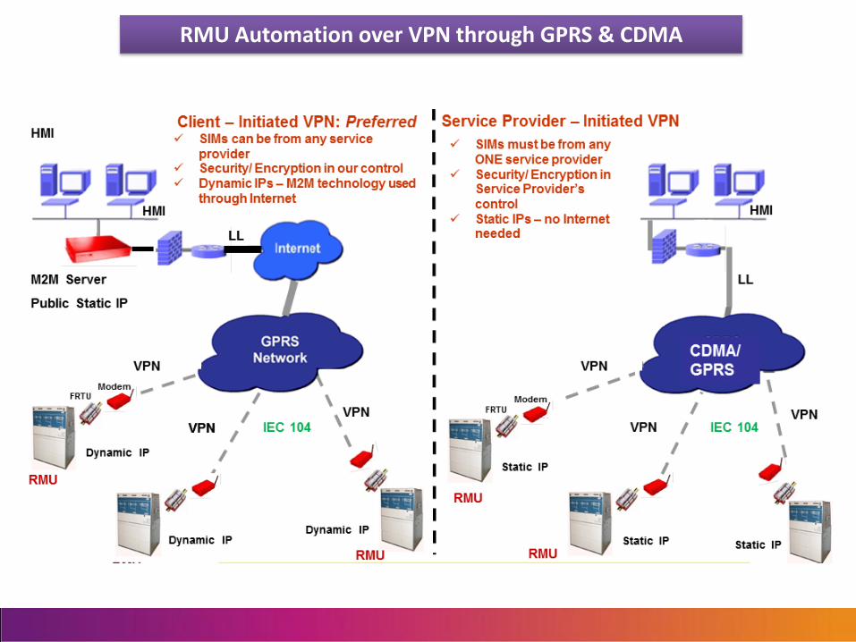
RMU Automation over VPN through GPRS & CDMA

IEC 104
RMU
`
FRTU
RMU
FRTU
RMU
FRTU
Remote
M/C
FRTU
Local M/C
FRTU FRTU
RMU RMU RMU
FRTU
RMU
O.F.
Link
O.F.
Link
IEC 104
• Reliable two-way communication link with low latency is required
• Communication Protocols:
• IEC 60870-5-101 / 104, DNP3
• Interoperability among devices must be ensured
Communication Infrastructure for RMU Automation over OFC – Present Practice

GSM / GPRS
Web Server
Intranet
Application Server
Communication Schematic for AMR System
OFC

Internet Cloud
Meter - Modem
Radio Interface
SGSN GGSN GW Router of
Service Provider
GW Router of ISP RT Server
Web Server
Application Server
Interface
Utility LAN
Network Infrastructure for Metering Data Management over GPRS

Future Roadmap in Communications

Concept of Smart Metering and Communication Networks involved

Backbone RMU no. 1
RMU no. 2
Master Bridge at Fiber PoP no. 1
DMS Server at Control Room
Relay on Road-side
Relay on Road-side
Router at Control Room
DA RF Redundant Route
DA RF Active Route
M M
M
M
M
Access Point at Fiber PoP no. 2
Remote Server for Metering
Smart Meters at Various Locations AMI RF Active Route
AMI RF Redundant Route
Access Point at Fiber PoP no. 3
AMI & DA over Wireless Communication Network Schematic
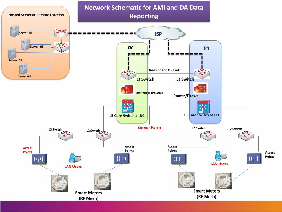
L3 Core Switch at DR
L2 Switch L2 Switch
Router/Firewall
Redundant OF Link
L3 Core Switch at DC
L2 Switch L2 Switch L2 Switch L2 Switch
Access Points
Access Points
Access Points Access
Points
Smart Meters (RF Mesh)
Smart Meters (RF Mesh)
ISP Server -01
Server -02
Server -04
Server -03
Server Farm
Router/Firewall
LAN Users LAN Users
DC DR
Hosted Server at Remote Location
Network Schematic for AMI and DA Data Reporting
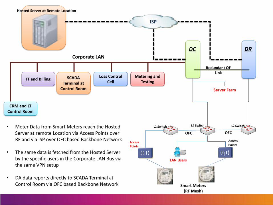
Redundant OF Link
L2 Switch L2 Switch L2 Switch
Access Points
Access Points
Smart Meters (RF Mesh)
ISP
Server Farm
LAN Users
DC DR
Hosted Server at Remote Location
IT and Billing SCADA Terminal at
Control Room
Loss Control Cell
CRM and LT Control Room
Metering and Testing
• Meter Data from Smart Meters reach the Hosted Server at remote Location via Access Points over RF and via ISP over OFC based Backbone Network
• The same data is fetched from the Hosted Server by the specific users in the Corporate LAN Bus via the same VPN setup
• DA data reports directly to SCADA Terminal at Control Room via OFC based Backbone Network
Corporate LAN
OFC OFC

Provider network Utility network – site 2 Utility network – site 1
RMU Automation
Access Points for RF Mesh Last-mile Communication
MDMS & SCADA Servers
Customer Router Customer Edge Router
Provider Ingress Router
Provider Router
Provider Egress Router Customer Router
Customer Edge Router
Multi-Protocol Label Switching (MPLS) as a Backhaul Communication Solution
VPN Tunnel between 2 Utility Locations
Network Management is in Scope of Service
Provider

Power System Protection Schemes
87L 87L
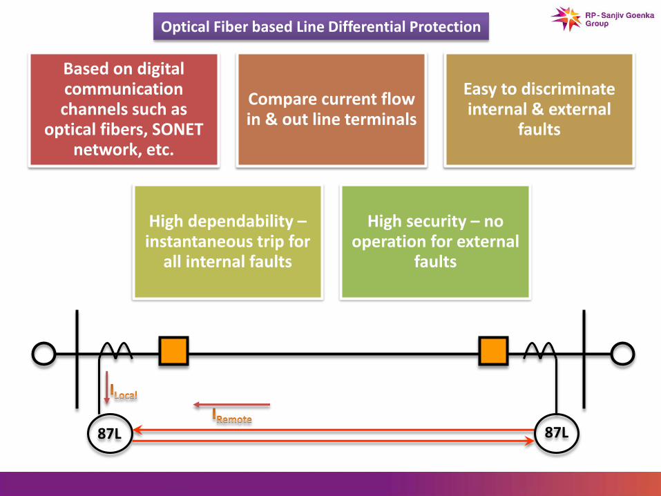
Based on digital communication channels such as
optical fibers, SONET network, etc.
Compare current flow in & out line terminals
Easy to discriminate internal & external
faults
High dependability – instantaneous trip for
all internal faults
High security – no operation for external
faults
Optical Fiber based Line Differential Protection
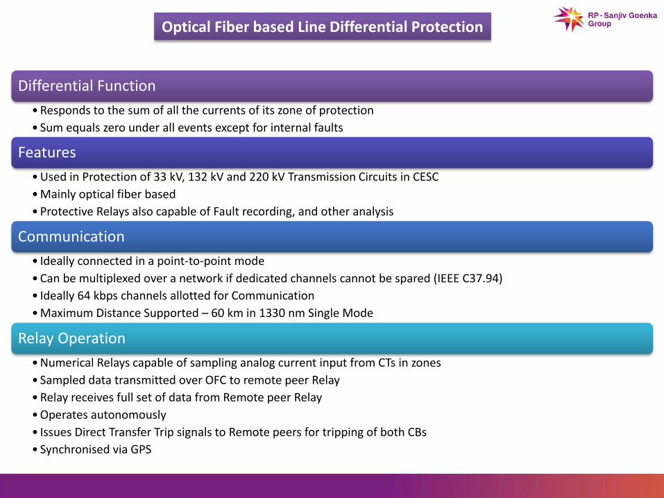
Optical Fiber based Line Differential Protection
Differential Function
• Responds to the sum of all the currents of its zone of protection
• Sum equals zero under all events except for internal faults
Features
• Used in Protection of 33 kV, 132 kV and 220 kV Transmission Circuits in CESC
• Mainly optical fiber based
• Protective Relays also capable of Fault recording, and other analysis
Communication
• Ideally connected in a point-to-point mode
• Can be multiplexed over a network if dedicated channels cannot be spared (IEEE C37.94)
• Ideally 64 kbps channels allotted for Communication
• Maximum Distance Supported – 60 km in 1330 nm Single Mode
Relay Operation
• Numerical Relays capable of sampling analog current input from CTs in zones
• Sampled data transmitted over OFC to remote peer Relay
• Relay receives full set of data from Remote peer Relay
• Operates autonomously
• Issues Direct Transfer Trip signals to Remote peers for tripping of both CBs
• Synchronised via GPS
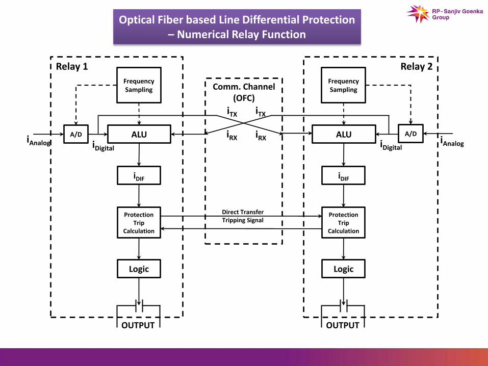
Optical Fiber based Line Differential Protection – Numerical Relay Function
Comm. Channel (OFC)
Relay 1
Frequency Sampling
A/D ALU
iDIF
Protection Trip
Calculation
Logic
iAnalog iDigital
OUTPUT
Relay 2
Frequency Sampling
A/D ALU
iDIF
Protection Trip
Calculation
Logic
iAnalog iDigital
OUTPUT
iTX
iRX
iTX
iRX
Direct Transfer Tripping Signal

MUX MUX
Optical Fiber based Line Differential Protection Scheme
Ideal usage of Line Differential Protection using Main and Standby Protection Relays over different Communication Routes

Distance Protection
IR ZL
Zs
VR
Uses both Current and Voltage to determine if
a fault is within the relay’s set zone of
protection
Settings based on positive and zero
sequence transmission line impedance
Measures phase and ground fault loops
Impedance zone has a fixed impedance reach
Greater instantaneous coverage
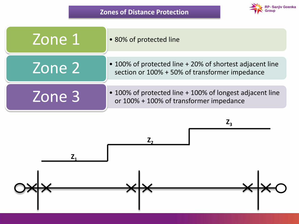
Zones of Distance Protection
Z1
Z2
Z3
• 80% of protected line Zone 1 • 100% of protected line + 20% of shortest adjacent line
section or 100% + 50% of transformer impedance Zone 2 • 100% of protected line + 100% of longest adjacent line
or 100% + 100% of transformer impedance Zone 3

Lockout Scheme – Contact Transfer
Generator Trip
Load Point 1 Load Point 2
Load Point 3
Load Point 4
Trip Contact Transfer
through SDH Backbone
Trip Contact Transfer
through SDH Backbone
Trip Contact Transfer
through SDH Backbone
Trip Contact Transfer
through SDH Backbone
Load Shed Load Shed
Load Shed
Load Shed
