distal radius surgical technique - conventus · pdf filesurgical technique. 2 table of...
TRANSCRIPT

1
3-DIMENSIONAL FRACTURE MANAGEMENT SYSTEM
DISTAL RADIUSSURGICAL TECHNIQUE

2
TABLE OF CONTENTS
Radial Technique Room Configuration and Patient Prep ..................................3
1 Reduction and Provisional Fixation .......................................3
2 Target Wire and Template .....................................................4
Cage Size ......................................................................4
Access Marking .............................................................4
3 Access — Incision ..................................................................5
Access — 2.5 mm Side Cut Drill ...................................5
4 Access — Guide Pin and 5.0 mm Drill ..................................6
5 Cavity Preparation .................................................................6
6 Cage Delivery and Locking ..................................................7
Cage Locking ................................................................7
7 Proximal Plate Application ....................................................8
8 Distal Fragment Fixation — Guide Wires ..............................8
Radial Side Suggestion .................................................9
Distal Fragment Fixation — 2.0 mm Drill ......................9
Ulnar Side Suggestion ...................................................9
Ulnar Side Volar Fragment Suggestion .........................9
9 Secure Fragments ...............................................................10
10 Confirm Anatomic Reconstruction and Remove K-Wires ....10
Post Operative Protocol ......................................................10
Dorsal Technique Room Configuration and Patient Prep ................................11
1 Closed Reduction and Provisional Fixation .........................11
2 Target Wire and Template ...................................................12
3 Access — Incision ................................................................12
Access — 2.5 mm Side Cut Drill .................................13
4 Access — Guide Pin and 5.0 mm Drill ................................13
5 Cavity Preparation ...............................................................13
6 CAGE Delivery and Locking ................................................14
7 Proximal Plate Application ..................................................14
8 Distal Fragment Fixation .....................................................15
9 Secure Fragments ...............................................................15
10 Confirm Anatomic Reconstruction
and Remove K-Wires ...........................................................15
Cage Removal Intra-Operative Removal .....................................................16
Post-Operative Removal .....................................................16

3
ROOM CONFIGURATION AND PATIENT PREPThe patient should be placed supine on the operating table, with the operative extremity positioned on a hand table. A brachial tourniquet should be applied as close to the axilla as possible to allow for maximal working exposure after draping. The mini C-arm should be positioned at the end of the hand table. Draping should not interfere with the surgeon’s ability to drill the radius at very shallow angles over the upper arm. Draping should extend upward at the shoulder, not upward from the arm.
1. REDUCTION AND PROVISIONAL FIXATIONThe distal radius fracture is reduced in a closed fashionutilizing multi-planar ligamentotaxis, distraction and manipulationto reduce the fracture anatomically. Small incisions may be madeto assist with reduction and a small osteotome or freer used to manipulate fragments, if needed.
.062” (1.5 mm) K-wires are placed to provide provisional stabiliza-tion. Radial and ulnar axial K-wires are inserted through longitudi-nal cutdown incisions over the radial styloid process and dorsal, ulnar radius. The resulting peripheral configuration of K-wires should leave the center of the distal radius free for eventual placement of the Conventus CAGE™- DR, as shown in the diagram to the left.
Initial K-wire placement can be done with a traditional cross-pinning technique. However, if this technique is employed, it will require immediate replacement of the initial K-wires with peripherally located K-wires prior to moving forward with the procedure.
For intra-articular fractures, insertion of a temporary transverse K-wire to hold reduction of intra-articular fragments may be nec-essary. This wire should be as distal as possible to allow for distal placement of the implant.
Reduction is confirmed at this time. Volar tilt, radial inclination, and radial length/ulnar variance are established during this provisional reduction step. Adjustments may be made prior to securing distal fragments (Steps 8-9). Take special care to confirm the presence/absence of an ulnar volar fragment on imaging.
Suggestion: The first .062” (1.5 mm) K-wire is driven from the 2nd dorsal compartment on the dorsal aspect of the distal radius fragment along the radial cortex of the radius. The K-wire is directed volarly and slightly radial, and then driven into the volar cortex of the radial shaft 2 cm proximal to the volar fracture line.
The second .062” (1.5 mm) K-wire is driven from the 4th dorsal compartment on the dorsal aspect of the DRUJ along the ulnar
Provisional reduction with dorsal- radial and dorsal-ulnar K-wires in place
• Place K-wires through fragments to stabilize the fracture
• Leave intramedullary space free of K-wires
AP View Lateral View
R A D I A L T E C H N I Q U E

4
cortex of the radius. The K-wire is directed volarly and slightly ulnar, and then driven into the volar cortex of the radial shaft approximately 2 cm proximal to the volar fracture line.
2. TARGET WIRE AND TEMPLATEThe distal apex of the template should be positioned 2–4 mm proxi-mal to the subchondral surface of the distal radius, between Lister’s tubercle and the center of the lunate facet so that the implant will support the loads in the wrist.
A .045” (1.1 mm) target K-wire is inserted at the desired location for the template’s apex and driven perpendicular to the radial shaft . This marks the templated location of the implant apex throughout the remainder of the procedure. If needed, the template can be placed over the wire (with the wire through the hole at the distal apex).
CAGE SIZESize is determined based on the location of the fracture and the patient’s anatomy. This is determined during initial templating. The access site for the Cage should be at least 7 mm proximal to the fracture. A small Cage should be selected for standard fractures and patients with smaller distal radius anatomy. A large Cage should be selected for more proximal fractures and patients with larger distal radius anatomy.
Two chevrons (^) on the proximal end of the DR Implant Template correspond to the two implant lengths and aid with visualization of possible insertion sites on the radius. The Access Guides also come in large and small designations for this purpose.
DR Implant Template Method — With the apex of the template fixed by the target K-wire, the proximal end is rotated until one chevron is aligned with the radial side of the radius at least 7 mm from the fracture as confirmed under fluoroscopy.
Access Guide Method — With the end of the small Access Guide fixed by the target K-wire, the proximal end is rotated until the tip is aligned with the radial side of the radius. Confirm under fluoroscopy that the distance between the tip and the fracture is at least 7 mm, and if not, try the large Access Guide.
The template may be outlined with marker on the skin to help visualize intended location through the remainder of the procedure.
ACCESS MARKINGThe Access Guide can be used for most patients. If the patient’s soft tissue makes it difficult to use the Access Guide (e.g., high BMI), the DR Implant Template should be used to locate the incision.
DR Implant Template Method — With the DR Implant Template in proper position, the skin just radial to the desired access site can be marked.
Access Guide Method — The appropriately-sized Access Guide is placed over the target K-wire and the tip is rotated down to the forearm while location central to the radius is confirmed. The skin is marked for the delivery access site.
Small Cage
Large Cage
DR Implant Template
Access Guide
5
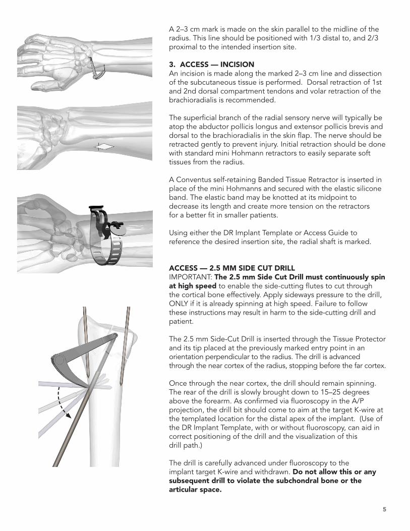
A 2–3 cm mark is made on the skin parallel to the midline of the radius. This line should be positioned with 1/3 distal to, and 2/3 proximal to the intended insertion site.
3. ACCESS — INCISIONAn incision is made along the marked 2–3 cm line and dissection of the subcutaneous tissue is performed. Dorsal retraction of 1st and 2nd dorsal compartment tendons and volar retraction of the brachioradialis is recommended.
The superficial branch of the radial sensory nerve will typically be atop the abductor pollicis longus and extensor pollicis brevis and dorsal to the brachioradialis in the skin flap. The nerve should be retracted gently to prevent injury. Initial retraction should be done with standard mini Hohmann retractors to easily separate soft tissues from the radius.
A Conventus self-retaining Banded Tissue Retractor is inserted in place of the mini Hohmanns and secured with the elastic silicone band. The elastic band may be knotted at its midpoint to decrease its length and create more tension on the retractors for a better fit in smaller patients.
Using either the DR Implant Template or Access Guide to reference the desired insertion site, the radial shaft is marked.
ACCESS — 2.5 MM SIDE CUT DRILLIMPORTANT: The 2.5 mm Side Cut Drill must continuously spin at high speed to enable the side-cutting flutes to cut through the cortical bone effectively. Apply sideways pressure to the drill, ONLY if it is already spinning at high speed. Failure to follow these instructions may result in harm to the side-cutting drill and patient.
The 2.5 mm Side-Cut Drill is inserted through the Tissue Protector and its tip placed at the previously marked entry point in an orientation perpendicular to the radius. The drill is advanced through the near cortex of the radius, stopping before the far cortex.
Once through the near cortex, the drill should remain spinning. The rear of the drill is slowly brought down to 15–25 degrees above the forearm. As confirmed via fluoroscopy in the A/P projection, the drill bit should come to aim at the target K-wire at the templated location for the distal apex of the implant. (Use of the DR Implant Template, with or without fluoroscopy, can aid in correct positioning of the drill and the visualization of this drill path.)
The drill is carefully advanced under fluoroscopy to the implant target K-wire and withdrawn. Do not allow this or any subsequent drill to violate the subchondral bone or the articular space.
6
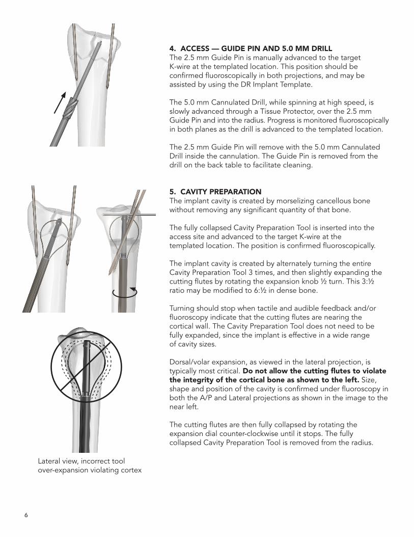
4. ACCESS — GUIDE PIN AND 5.0 MM DRILLThe 2.5 mm Guide Pin is manually advanced to the target K-wire at the templated location. This position should be confirmed fluoroscopically in both projections, and may be assisted by using the DR Implant Template.
The 5.0 mm Cannulated Drill, while spinning at high speed, is slowly advanced through a Tissue Protector, over the 2.5 mm Guide Pin and into the radius. Progress is monitored fluoroscopically in both planes as the drill is advanced to the templated location.
The 2.5 mm Guide Pin will remove with the 5.0 mm Cannulated Drill inside the cannulation. The Guide Pin is removed from the drill on the back table to facilitate cleaning.
5. CAVITY PREPARATIONThe implant cavity is created by morselizing cancellous bone without removing any significant quantity of that bone.
The fully collapsed Cavity Preparation Tool is inserted into the access site and advanced to the target K-wire at the templated location. The position is confirmed fluoroscopically.
The implant cavity is created by alternately turning the entire Cavity Preparation Tool 3 times, and then slightly expanding the cutting flutes by rotating the expansion knob ½ turn. This 3:½ ratio may be modified to 6:½ in dense bone.
Turning should stop when tactile and audible feedback and/or fluoroscopy indicate that the cutting flutes are nearing the cortical wall. The Cavity Preparation Tool does not need to be fully expanded, since the implant is effective in a wide range of cavity sizes.
Dorsal/volar expansion, as viewed in the lateral projection, is typically most critical. Do not allow the cutting flutes to violate the integrity of the cortical bone as shown to the left. Size, shape and position of the cavity is confirmed under fluoroscopy in both the A/P and Lateral projections as shown in the image to the near left.
The cutting flutes are then fully collapsed by rotating the expansion dial counter-clockwise until it stops. The fully collapsed Cavity Preparation Tool is removed from the radius.
Lateral view, incorrect tool over-expansion violating cortex

7
6. CAGE DELIVERY AND LOCKING The correct size Conventus Cage - DR is selected.
With the forearm in neutral supination/pronation, the implant delivery device is inserted into the access site and advanced to the templated location inside the prepared cavity. Location is confirmed under fluoroscopy.
The delivery device should be oriented as shown, with the arrow on the handle on the side away from the patient.
The Cage is deployed into the prepared cavity by holding the black handle body stationary and rotating the rear grey knob clockwise until the implant is fully exposed and expanded.
The expansion and position of the Cage is confirmed under fluo-roscopy in both the A/P and Lateral projections.
CAGE LOCKINGOnce the Cage is in the desired location, the implant must be locked to achieve maximum structural strength.
Lock Cage by rotating small grey driver knob on the side of the delivery system to advance locking screw (approx. 12 turns). A slight torque wind-up in the knob should be felt when the locking screw is fully seated. The implant deployment handle can now be removed. The H8 Cannulated Driver and Driver Handle should be used to finish tightening the locking screw, if needed, with care taken not to push the Cage into the bone. Continuing to turn the driver after the locking screw is tightened may result in the entire Cage spinning. If this occurs, continue to turn the driver in a clockwise direction until the implant is again properly aligned.
Visually confirm locking screw is advanced clear of hole on implant tail (Proximal Plate eyelet).

8
7. PROXIMAL PLATE APPLICATIONThe 2.2 mm Drill is inserted through the Tissue Protector, and brought to the patient’s arm. The drill is advanced through the Proximal Plate eyelet of the Cage and through the far cortex perpendicular to the shaft of the radius.
Screw lengths are measured through the Proximal Plate using the bi-cortical depth gauge.
The appropriate length headed screw is delivered through the distal hole of the Proximal Plate and the Cage Proximal Plate eye-let, and then into the far cortex (unicortical), but not fully tight-ened. The proximal hole is drilled bicortically and the appropriate length headed screw is delivered. Both screws can now be fully tightened, securing the implant proximally to the radial shaft. Suggestion: A .045 K-wire placed through the first cannulated screw can be used to facilitate screw placement and as a visual guide for parallel drilling and placement of the second screw.
8. DISTAL FRAGMENT FIXATION — GUIDE WIRESThe most appropriate distal screw pattern will depend on the fracture. The majority of distal radius fractures can be adequately stabilized with two screws originating from the distal radial frag-ments, passing through the Cage, with one or more of the screws engaged bicortically into the radial shaft.
Distal screws should be placed sequentially. The process for placing each screw should be completed before initiating placement of additional screws to minimize the potential for interference.
.045” (1.1 mm) guide wires are inserted in the eventual locations for the cannulated 2.7 mm screws. As previously noted, guide wires can be inserted using the reduction wire locations. Alternately, small stab incisions may be made at the guide wire insertion points per surgeon preference. Soft tissue cut down is recommended.
Guide wire tips are advanced to the desired locations for the screw tips (as noted below), measurements are taken, and then guide wires are advanced to provide resistance to unintentional removal with the drill in the next step.
NOTE: Screw measurements may need to be adjusted to account for the following:• Effect of radiographic projection angle on the actual location
of the screw tip relative to the cortex,• Curvature of the starting point on the bone and extent to
which the screw is counter-sunk,• Compression of the fragments due to screw placement.
1st
2nd

9
Radial Side Suggestion — A .045” (1.1 mm) guide wire is driven from the radial aspect of the radial styloid, between first and second compartments, through the center of the Cage and then through the far cortex of the radial shaft 1–2 cm proximal to the fracture.
If the proximal shaft displaces relative to the distal fragments during radial styloid screw placement, thus disrupting the DRUJ, a Hohmann retractor can be inserted into the wound over the dorsal ulnar aspect of the proximal radial shaft for reduction and counter-pressure as the bone is drilled from radial to ulnar.
DISTAL FRAGMENT FIXATION — 2.0 MM DRILLUsing the 2.0 mm Cannulated Drill, the distal radius is prepared for the 2.7 mm cannulated screws. The drill should rotate forward/clockwise while drilling the near and far cortices, but should travel through the implant in oscillation or reverse mode.
When using the Tissue Protector during drilling, excessive bend-ing or flexing should be avoided to prevent instrument damage.
Ulnar Side Suggestion — A .045” (1.1 mm) guide wire is driven from the dorsal aspect of the distal ulnar corner originating between the EIP and the EDC/L through the center of the Cage ending just inside the cortex of the radial shaft 1–2 cm prox-imal to the fracture.
The .045” Plunger may assist in keeping the guide wires in place during drill removal, particularly if drilling bi-cortically. This is help-ful for placement of screws into the bone over the guide wires.
Ulnar Side Volar Fragment Suggestion — The distal fixation of the ulnar side of the distal radius, or ulnar sided fragment, can be accomplished using a radial side approach with insertion from either the volar or dorsal aspect. The advantage of this approach is in capturing the volar tubercle fragment without having to dis-sect through the radioscapholunate, and radiotriquetrial parts of the radio-carpal ligament.
NOTE: If this screw is required, it should be inserted before the dorsal ulnar side screw.
Radial screw guide wire
Ulnar screw guide wire
Ulnar volar fragment screw guide wire
10
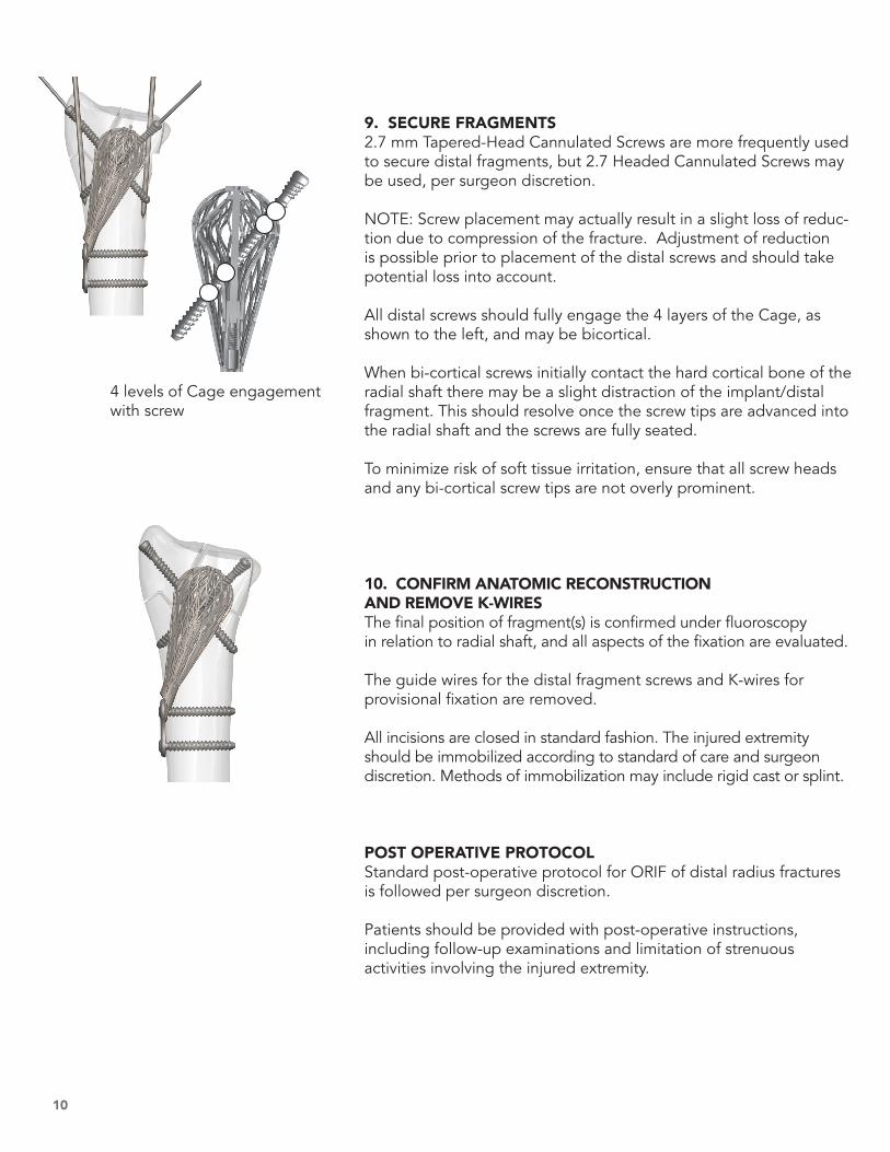
9. SECURE FRAGMENTS 2.7 mm Tapered-Head Cannulated Screws are more frequently used to secure distal fragments, but 2.7 Headed Cannulated Screws may be used, per surgeon discretion.
NOTE: Screw placement may actually result in a slight loss of reduc-tion due to compression of the fracture. Adjustment of reduction is possible prior to placement of the distal screws and should take potential loss into account.
All distal screws should fully engage the 4 layers of the Cage, as shown to the left, and may be bicortical.
When bi-cortical screws initially contact the hard cortical bone of the radial shaft there may be a slight distraction of the implant/distal fragment. This should resolve once the screw tips are advanced into the radial shaft and the screws are fully seated.
To minimize risk of soft tissue irritation, ensure that all screw heads and any bi-cortical screw tips are not overly prominent.
10. CONFIRM ANATOMIC RECONSTRUCTION AND REMOVE K-WIRESThe final position of fragment(s) is confirmed under fluoroscopy in relation to radial shaft, and all aspects of the fixation are evaluated.
The guide wires for the distal fragment screws and K-wires for provisional fixation are removed.
All incisions are closed in standard fashion. The injured extremity should be immobilized according to standard of care and surgeon discretion. Methods of immobilization may include rigid cast or splint.
POST OPERATIVE PROTOCOLStandard post-operative protocol for ORIF of distal radius fractures is followed per surgeon discretion.
Patients should be provided with post-operative instructions, including follow-up examinations and limitation of strenuous activities involving the injured extremity.
4 levels of Cage engagement with screw
11
ROOM CONFIGURATION AND PATIENT PREP
The patient should be placed supine on the operating table, with the operative extremity positioned on a hand table. A brachial tourniquet should be applied as close to the axilla as possible to allow for maximal working exposure after draping. The mini C-arm should be positioned at the end of the hand table. Draping should not interfere with the surgeon’s ability to drill the radius at very shallow angles over the upper arm. Draping should extend upward at the shoulder, not upward from the arm.
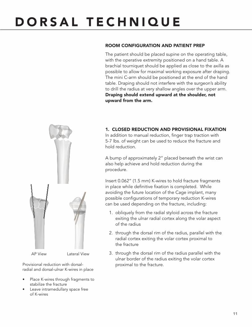
1. CLOSED REDUCTION AND PROVISIONAL FIXATIONIn addition to manual reduction, finger trap traction with 5-7 lbs. of weight can be used to reduce the fracture and hold reduction.
A bump of approximately 2” placed beneath the wrist can also help achieve and hold reduction during the procedure.
Insert 0.062” (1.5 mm) K-wires to hold fracture fragments in place while definitive fixation is completed. While avoiding the future location of the Cage implant, many possible configurations of temporary reduction K-wires can be used depending on the fracture, including:
1. obliquely from the radial styloid across the fracture exiting the ulnar radial cortex along the volar aspect of the radius
2. through the dorsal rim of the radius, parallel with the radial cortex exiting the volar cortex proximal to the fracture
3. through the dorsal rim of the radius parallel with the ulnar border of the radius exiting the volar cortex proximal to the fracture.Provisional reduction with dorsal-
radial and dorsal-ulnar K-wires in place
• Place K-wires through fragments to stabilize the fracture
• Leave intramedullary space free of K-wires
AP View Lateral View
D O R S A L T E C H N I Q U E
12
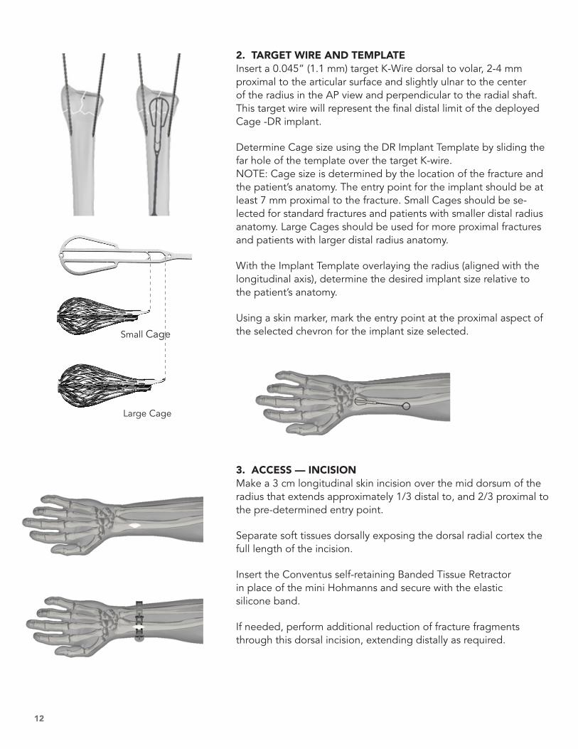
2. TARGET WIRE AND TEMPLATEInsert a 0.045” (1.1 mm) target K-Wire dorsal to volar, 2-4 mm proximal to the articular surface and slightly ulnar to the center of the radius in the AP view and perpendicular to the radial shaft. This target wire will represent the final distal limit of the deployed Cage -DR implant.
Determine Cage size using the DR Implant Template by sliding the far hole of the template over the target K-wire. NOTE: Cage size is determined by the location of the fracture and the patient’s anatomy. The entry point for the implant should be at least 7 mm proximal to the fracture. Small Cages should be se-lected for standard fractures and patients with smaller distal radius anatomy. Large Cages should be used for more proximal fractures and patients with larger distal radius anatomy.
With the Implant Template overlaying the radius (aligned with the longitudinal axis), determine the desired implant size relative to the patient’s anatomy.
Using a skin marker, mark the entry point at the proximal aspect of the selected chevron for the implant size selected.
3. ACCESS — INCISIONMake a 3 cm longitudinal skin incision over the mid dorsum of the radius that extends approximately 1/3 distal to, and 2/3 proximal to the pre-determined entry point.
Separate soft tissues dorsally exposing the dorsal radial cortex the full length of the incision.
Insert the Conventus self-retaining Banded Tissue Retractor in place of the mini Hohmanns and secure with the elastic silicone band.
If needed, perform additional reduction of fracture fragments through this dorsal incision, extending distally as required.
Small Cage
Large Cage
13
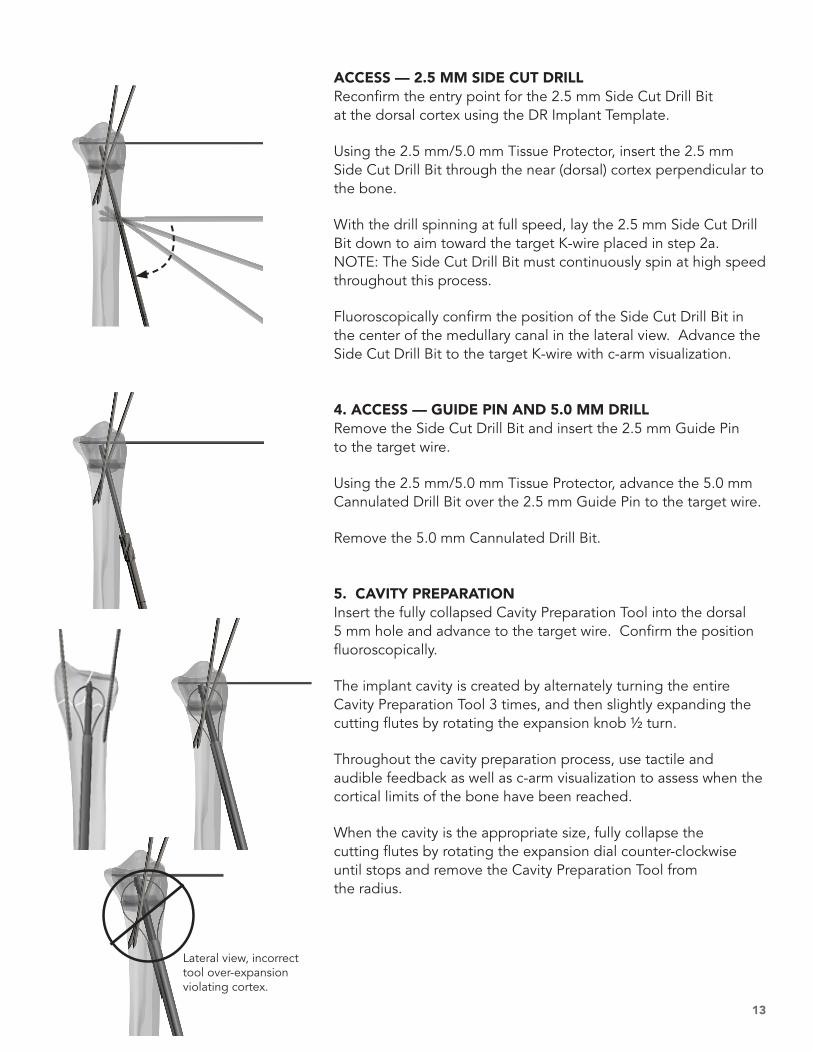
ACCESS — 2.5 MM SIDE CUT DRILLReconfirm the entry point for the 2.5 mm Side Cut Drill Bit at the dorsal cortex using the DR Implant Template.
Using the 2.5 mm/5.0 mm Tissue Protector, insert the 2.5 mm Side Cut Drill Bit through the near (dorsal) cortex perpendicular to the bone.
With the drill spinning at full speed, lay the 2.5 mm Side Cut Drill Bit down to aim toward the target K-wire placed in step 2a. NOTE: The Side Cut Drill Bit must continuously spin at high speed throughout this process.
Fluoroscopically confirm the position of the Side Cut Drill Bit in the center of the medullary canal in the lateral view. Advance the Side Cut Drill Bit to the target K-wire with c-arm visualization.
4. ACCESS — GUIDE PIN AND 5.0 MM DRILLRemove the Side Cut Drill Bit and insert the 2.5 mm Guide Pin to the target wire.
Using the 2.5 mm/5.0 mm Tissue Protector, advance the 5.0 mm Cannulated Drill Bit over the 2.5 mm Guide Pin to the target wire.
Remove the 5.0 mm Cannulated Drill Bit.
5. CAVITY PREPARATIONInsert the fully collapsed Cavity Preparation Tool into the dorsal 5 mm hole and advance to the target wire. Confirm the position fluoroscopically.
The implant cavity is created by alternately turning the entire Cavity Preparation Tool 3 times, and then slightly expanding the cutting flutes by rotating the expansion knob ½ turn.
Throughout the cavity preparation process, use tactile and audible feedback as well as c-arm visualization to assess when the cortical limits of the bone have been reached.
When the cavity is the appropriate size, fully collapse the cutting flutes by rotating the expansion dial counter-clockwise until stops and remove the Cavity Preparation Tool from the radius.
Lateral view, incorrect tool over-expansion violating cortex.

14
6. CAGE DELIVERY AND LOCKINGSelect the appropriate size Cage -DR Implant which comes pre-loaded in the delivery device.
Insert the delivery device into the dorsal 5 mm hole and advance to the target wire. Confirm the position fluoroscopically.
Deploy the Cage -DR Implant into the prepared cavity by holding the black handle body stationary and rotating the rear grey knob clockwise until the implant is fully exposed and expanded.
When the Cage is in the desired location and expanded (as confirmed by fluoroscopy), lock the device by rotating the small gray knob on the side of the handle clockwise to advance the locking screw (approximately 12 turns) and remove the implant delivery handle.
NOTE: If fine tuning of the volar tilt or radial inclination is desired, retract the 0.062” (1.6 mm) K-wires across the fracture, reduce the fracture, and then while manually holding the reduction, advance the K-wires across the fracture again.
7. PROXIMAL PLATE APPLICATIONFor optimal stability, two screws are inserted proximally through the Cage Proximal Plate. The most distal of these screws will also pass through the implant Proximal Plate eyelet.
The 2.2 mm Drill Bit is inserted through the tissue protector and advanced through the implant proximal plate eyelet and through the far cortex perpendicular to the shaft of the radius.
Screw lengths are measured through the Proximal Plate using the Bi-cortical Depth Gauge.
Insert the appropriate length of headed 2.7 mm Screw using the H8 Cannulated Driver and Driver Handle, but do not fully tighten.
Repeat this process for the proximal hole. Both screws can then be fully tightened.

15
8. DISTAL FRAGMENT FIXATIONUsing standard cannulated screw technique, 2.7 mm distal screws can be inserted through the cage freehand or using the Fragment Targeting Jig to ensure they target near the center of the Cage. Screw locations can be customized to adapt to the needs of each fracture.
The radial styloid screw is inserted through a cut down incision protecting the branches of the radial nerve and the dorsal ulnar corner screw through a cut down protecting the 5 dorsal com-partment tendon. If a volar ulnar corner fragment is present, it is best reduced and fixed to the Cage through a 2 cm longi-tudinal incision centered palmarly between the flexor tendons and the ulnar neurovascular bundle.
Insert a 0.045” (1.1 mm) K-Wire in the desired screw location and advance to the desired locations for the screw tips.
Measure screw length using the Screw Sizer.
Drill over the K-wire using the 2.0 mm Cannulated Drill Bit.
9. SECURE FRAGMENTSSelect the appropriate length and type (headed or tapered head) of 2.7 mm Cannulated Screw and insert it over the K-wire using the H8 Cannulated Driver and Driver Handle. The distal screws should engage both cortices and the central portion of the cage for optimal fixation.
10. CONFIRM ANATOMIC RECONSTRUCTION AND REMOVE K-WIRESConfirm final reduction and implant placement fluoroscopically.
Remove all temporary K-wires.
All incisions are closed in standard fashion.
16
10200 73rd Avenue NorthSuite 122Maple Grove, MN 55369
Office: 763.515.5000US Customer Service: 855.41UNION (418.6466)
Products listed may not be available in all markets.
1699-1 Rev 10
1
3 4
2
5 6 7
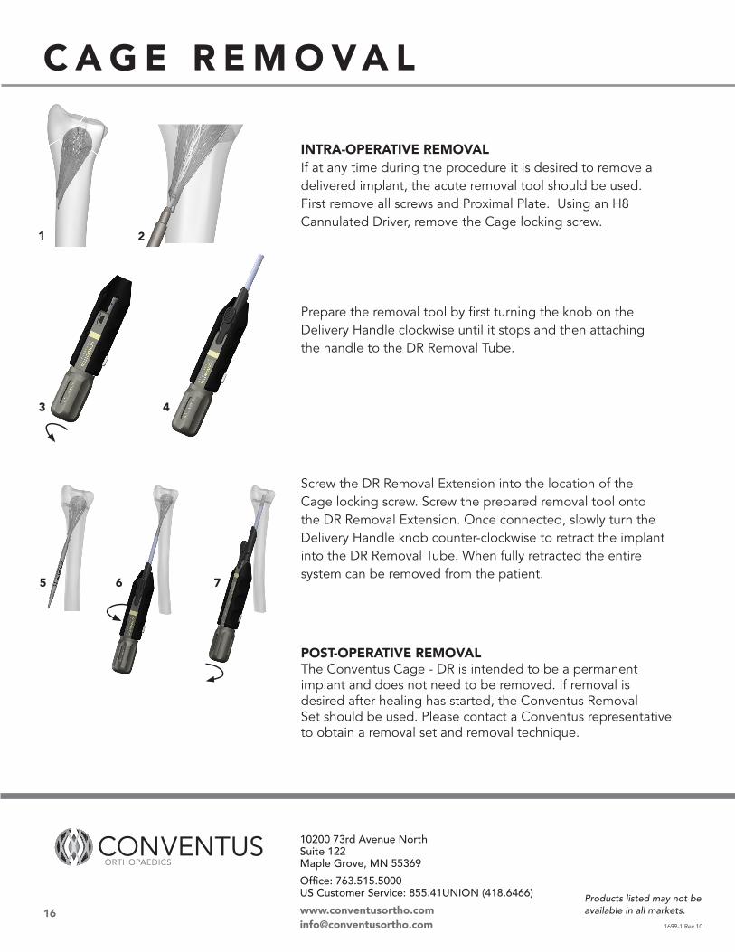
INTRA-OPERATIVE REMOVALIf at any time during the procedure it is desired to remove a delivered implant, the acute removal tool should be used. First remove all screws and Proximal Plate. Using an H8 Cannulated Driver, remove the Cage locking screw.
Prepare the removal tool by first turning the knob on the Delivery Handle clockwise until it stops and then attaching the handle to the DR Removal Tube.
Screw the DR Removal Extension into the location of the Cage locking screw. Screw the prepared removal tool onto the DR Removal Extension. Once connected, slowly turn the Delivery Handle knob counter-clockwise to retract the implant into the DR Removal Tube. When fully retracted the entire system can be removed from the patient.
POST-OPERATIVE REMOVALThe Conventus Cage - DR is intended to be a permanent implant and does not need to be removed. If removal is desired after healing has started, the Conventus Removal Set should be used. Please contact a Conventus representative to obtain a removal set and removal technique.
C A G E R E M O VA L