distributed by: na•mal tohdmi bfuinti suev ... directivity index of a circular piston of diameter...
TRANSCRIPT
AD-778 660APPROXIMATIONS TO THE DIRECTIVITY
INDEX
Robert J. Bobber
Naval Research LaboratoryWashington, D. C.
I May 1974
V
iZ 5
DISTRIBUTED BY:
mumI
Na•mal Tohdmi bfuinti Suev"U.. SDEPARTMENT OF COMMERCE5285 Port Roto, SpdntIfekl If. 22151

UNCQLASSTFPTDSECURITY CLASSIFICATION OF THIS PAGE ("on Data nt..t,. 77 1-
READ INSTRUCTIONSREPORT DOCUMENTATION PAGE BEFORE COMPLETING FORM1. REPORT NUMBER 12. GOVT ACCESSION NO 3. RECIPIENT*S CATALOG NUMS-R
NRL Report 7"750I _
4. TITLE (and Subtitle) S. TYPE OF REPORT & PERIOD COVERED
Final report on one part ofAPPROXIMATIONS TO THE DI.ECTIVITY INDEX the problem
6. PEqtPORMING ORG. REPORT NUMBER
7. AUTHOR(s) III. CONTRACT OR GRANT NUMBER(I)
Robert J. Bobber2. PERFORMING ORGANIZATION NAME AND ADDRESS 10. PROGRAM ELEMENT. PROJECT. TASK
AREA & WORK UNIT NUMBERSNaval Research LaboratoryUnderwater Sound Reference Division NRL Problem K03-'30.401r.O. Box 8337. Orlando. FL 3280f r__
11. CONTROLLING OFFICE NAME AND ADDRESS 12. REPORT DATE
Department of the Navy 1 May 1974Office of Naval Research I1. NUMBER OF PAGES
Arlinqton, VA 22217 iii + 1714. MONITORING AGE.,CY NAME A AOORESS(It difelremnt ho ComntroltnjI Office) IS. SECURITY CLASS. (of thle tsoft)
' UNCLASSIFIED"IS& DECLASStICATION/DOWN GRADING
SCHEDULE
i 16. 01STRIUTION STATEMENT (of tile RApot)
Approved for public release; distribution unlimited
S17. DOzTRIBUTION STATEMENT (of the abstract mftered on l•ock 2It I! dillerenl be Repit)
III. SUPPLEMENTARY NOTES
DDC
19. KEY WORDS (Cofmu oen ftwerse old* iflnecoeomy &Mt dmnhfy by bloc nsbor)4
Diretivty idexReomuced byIS Directivity index NATIONAL TECHNICALUnderwater sound transducers INFORMATION SERVICEU S D00-,ment of Cornmeme
Spriu~igceld VA 2215a
20. ABSTRACT (Conmmhn an reveise ilde If nocoary and Identify by block nmwor)
Directivity indexes of three different underwater sound transducers havebeen measured or computed by five different methods: (1) theoretical cezcula-L tions using piston area or line length, (2) beam-width measurement and theo-retical calculation, (3) pattern measurement and graphical integration, (4)direct digital directivity ijaex measuring system, and (5) diffuse-sound methThe results indicate that the directivity index of any ordinary transducer canbe obtained from calculations based on known configurations and dimensions or
D! ''D 473 EDITION OF NOV GSIS OBSOLETE sJ CAWA. PI UNCLASSIFIED-•-•- S/N 102-04- Ei| I • SE.CURITY •L.AMIFICATION OFr TIrlIS PAG9 (Wlnm be~e, 0| Br*
UNCIASSIFIED.LU•qITY CLASSIW.ICATION OF THIS PAGE(Wmas Date Znter*4)
20. Abstract (continued)
beam-width measurements with a degree of reliability and accuracy that is noworse than any measurement technique and that, in most cases, elaboratemeasurements for determining directivity index are not justified.
II
| ii UNCLASSIFIEDSECURITY CLAS;ICATIOU OF THIS PAGE(UI.. DO Uate re.
4b

Contents
Introduction . .. . . .. .. .. . .. .. .. . . . . .. . . . . . 1Comparison of Five Methods .......... ..................... 1Energy in Minor Lobes ....... ... ....................... 4Circular Pistons ......................................... 5Rectangular and Other Pistons ....... .................... 7Radiating Areas ....... ..... ........................... 8Beam Widths ....... ... ... ............................. 9Rear Lobes ............. .............................. 9Radiation Resistance ......... ......................... 10Line Sources ........ ... ............................. 11Shaded Transducers ........ ... ......................... 13Arrays with Mutual Coupling ......... ..................... 15Conclusion ........... .............................. 16Acknowledgarnent ....... ..... ........................... 16References ........... .............................. 16
Figures
1. Array configurations for (a) one quadrant of type P27transducer, (b) one quadrant of type F33 transducer, and(c) type F37 line transducer ....... ................... .
2. The directivity index of (a) type F27 transducer, (b)type F33 transducer, and (c) type F37 transducer, asdetermined by methods 1, 2, 3, 4, and 5 .... ................. 4
3. The directivity index of a circular piston of diameter dwithout baffle, with a rigid plane baffle, in the end ofan infinitely long rigid pipe, and as approximated by theexpression 10 log (4wA/A 2 ) ...... ....... .................... 6
4. The directivity index of a rectangular piston in aninfinite plane rigid baffle as a function of length Lor width W ......... ......... ............................ 7
5. The direnti-zity index of a line source according toStenzel's exact expression (Eq. (8)), and three degreesof approximation by Eq. (10) ....... ................... ... 12
6. Major lobes of patterns for a uniform line, a linearlytapered line, and lO-element binomially shaded line array . . 15
Tables
1. Percentage of acoustic energy in each lobe of an idealpiston with a diameter of d/)A wavelengths, and an idealline with a length of L/f wavelengths ........ ............. 5
2. Correction (in decibels) to calculated directivity indexas a function of rear lobe height ............ ................ 10
•- iii
\4

APPROXIMATIONS TO THE DIRECTIVITY INDEX
Introduction
The directivity index has long been an important parameter in eval-uatLig some types of electroacoustic transducers--particularly in sonarapplications. It is a difficult parameter to analyze and measure becausea three-dimensional integration of the radiation pattern is involved.For this rea-con, approximations have been widely used in both the theoryand measurement. In spite of the fact that Stenzel [1], Molloy [2], andothers worked out the fundamental theory many years ago, there has beenlittle quantitative analysis of the theoretical and measurement apprcxi-mations. At the same time, transducer designers have either gone toelaborate and costly techniques to measure the directivity index [3-8],or have used %try simple computational aids such as special slide rulesthat are based on idealized models [9]. The purpose of this study wasto compare the results of these two extremes in methodology, to quantifysome of the limits of approximations, to identify the most feasiblemethod of deterrmining the directivity index, and to report some resultsof two little known or used measurement methods. An unexpected sidelight has been the identification of an error in Stenzel's originalanalysis and some errors in translating Stenzel's work into English[10.11] and in preparing a second edition of his book [12].
The principal conclusion from this study was that, in most cases,elaborate measurements for determining the directivity index are notjustified by the accuracy or precision oi the results.
Comparison of Five Methods
D.3rectivity factors of three different underwater sound transducershave been measured or computed by five different methods.
The three transducers are NRL-USRD types F27, F33, and F37. TheF27 appro.mirates a uniform circular piston in a rigid baffle, as shownin Fig. la. It is compzised of an array of 55 lead metaniobate disks.The type F33 approximates a nonuniform circular piston in a rigid baffle,as shown in Fig. lb. It is comprised of two arrays. The outer arraycontains 64 barium titanate rectangular plates; the inner array, 12 lead
1|

zirconate circular disks. The transducer was designed with the dual con-figuration to provide a wide useful frequency range. For the experimentsdescribed here, the two arrays were electrically connected and used asone array. The type F37 approximates a uniform line, or thin cylinder,as shown in Fig. 1c. It is comprised of a line of eight lead zirconatecapped cylinders.
! .18EIF1]E]-+ h..,8 .LID-
CM CS CM
(a) (b) (C)
Fig. 1. Array configurations for (a) one quadrant of typeF27 transducer, (b) one quadrant of type F33 transducer,and (c) type F37 line transducer.
The five methods are:
1. TheoreticaZ CaZlcuZations Using Pistn Area or Line Length. Thismethod requires only theoretical calculatit-.. based on well-known approxi-mations. The directivity factor of a pisten in an infinite rigid baffleis given approximately by the expression 41rA/A 2 , where A is the pistonarea and A is the wavelength. Foy A line or thin cylinder, the corre-sponding expression is 2L/A, where L is the length. These are simpleexpressions, but unc .tainties usually arise in ascertaining A and Lbecause, in practice, both pistons and lines are really arrays of elements.The spaces between the elements u.uaa'ly are included in A and L, but theeffective edges or ends of the arral ,s are more indefinite, and generallyintroduce an uncertainty of about 5% for L and 10% for A.
2. Beaw-Width Measurement at.d Theoraticat Calculation. The beam widthof the radiation pattern was measured. The transducer size and shape wereinferred from these measurements, and the directivity factor then was cal-culated in a manner similar to the first method. In both calculationmethods, it is assumed that the differences between the theoretical andreal minor lobe structures in the pattern are negligible.
I
-- _

3. Pattern Measurement and GraphicaZ Integration. A number of two-dimensional patterns were plotted. Then graphical integrations were carriedout to ascertain apprgximately the three-dimensional pattern. This is astandard method, but very time consuming unless the pattern has circularsymmetry about at least one axis, or some computerized technique [4,5] isused for the integration.
4. Direct Digital Directivity Index Measuring System. A new digitalsystem was used [6,7]. A seven-element semicircular hydrophone array wasswept through a spherical surface around the transducer, and 25; samplesof the radiated sound pressure level were obtained in a few minutes. The252 values were processed by digital comput _r methods to obtain the direc-tivity factor in a short time. No patterns, per se, are required for thismethod.
5. Diffuse-Sound Method. The identity between the directiivity factorand the ratio of the free-field to the difiuse-field receiving sensitivityof a transducer [13] was used. Diffuse fields or reverberent chambershave been little used in underwater acoustics because of the long wave-lengths and difficulties in obtaining large impedances mismatches. Thediffuse field sensitivities used ir, this experiment were obtained by B. G.Watters in the reverberation tank at the Bolt, Beranek, and Newman companyi- Cambridge, Mass. [14]. This tank has the dimensions 9.75 x 7.01 x 4.27me'e.'rs and reverheration times as long as 5 seconds. The only other re-poited use of this method is from Reznikov and Snytko [15] who used bothspatial and temporal averaging in a small water-filled vessel. Their workis difficult to assess or use because of an incomplete description of thetransducer, the use of unexplained corrections, and results which showthat the directivity factor of a cylindricai transducer is not proportionalto frequency, as it should be.
The directivity index, or ten times the logarithm of the directivityfactor, is shown in Fig. 2 for the three transducers as determined by thefive methods. The calculated directivity indexes for the types F27 andF33 from the first method are shown as broad lines, 0.5 dB wide, becauseof the uncertainty in the value to be used for the area A.
!:he a, reement among all methods except the fifth (diffuse field) isunusuallt good for the F33--so good that all data points fall within the0.5-SB spread of the calculated values. The diffuse field data are clearlytoo high. The discrepancy probably is due to the imperfect diffuseness ofthe field.
The scatter among the methods is greater for the F27, but the averageof the three experimental methods (3, 4, and 5) agrees well with the twocalculation methods (I and 2).
For the F37, four of the five methods are in good agreement above.SE 20 kHz,, but this time it is the digital method that does not agree; how-
ever, ¢nly one (25 kHz) of the three data points is widely different.Below 20 kHz the diffuse field method is again too high.
t~j 3
_ _

25 I 2 15,
35
X I& 2 IC 5-
4 -
21.2.3
11 . .3C 5
10 I
15 15 220 3 ~~1.2.3.4 10 i .0 30
frequency (kHz) Frequency (kMz)(0) (c
10 Is 20Frequency (kHz)
(b)
Fig. 2. The dixectivity index of (a) type F27 transducer,(b) type F33 transducer, and (c) type F37 transducer, as de-termined by methods 1, 2, 3, 4, and 5.
The data show that the diffuse-field method in the BEN tank should !,elimited to 25 kHz and higher frequencies. Beyond that, there is not suf-ficient consistency in the data to conclude that one of the three experi-mental methods is to be preferred.
7he one conclusion that emerges from the experiment is that the direc-tivity index obtained from the theoretical or from the beam width calcu-lations is as reliable as any of the experimental methods, and it appearsfutile to go to elaborate measurements for transducers of conventionalshapes.
Energy in Minor Lobes
Table I srows the acousti-, energy distribution among the major andminor lobes in typical patternb It is evident from this table that minorlobes contribute very little to the Mirectivity factor or inde=. Neglect-ing all the minor lobes w=ulc introduce an error of less than 0.8 dB fora piston and less than 0.4 dB tor a line. In practice, of course, it isnot a matter of entirely neglecting the minor lobes, but rather neglectingthe difference between the idealized and the real pattern. Clearly, I-or 2-dB variations in the height of the first minor lobe asd even largervariations in the others are not going to make perceptil le differencesbetween the real directivity index and the directivity -ndex based on. anideal zodel and measurements of only the major lobe. This fact, of course,supports the thesis that once the beam width of the major lobe is known,along with the basic configuration of the radiator (circle, rectangle,cylinder, etc.), and the knowledge that the minor lobe structure is notradically abnormal, no further measurement is necessary.
4 -

Table 1. Percentage of acoustic energy in each lobe of an idealpiston with a diameter of d/), wavelengths, and an ideal line with alength of L/X wavelen!ýths.
Minor4 Lobes
Majord/f L/), Lobe 1 2 3 4 5 6 7
2 0.85 0.15
3 .84 .09 0.07
5 .84 .08 .03 0.02 0.03
8 .84 .08 .03 .02 .01 0.00 0.00 0.02
2 0.95 0.05
3 .93 .05 0.02
Is .92 .05 .02 0.01 0.00
8 .92 .05 .01 .01 .00 0.00 0.00 0.00
EAn interesting side light is shown in Table I. The energy -n suc-k cesaive side lobes does not always diminish steadily. In large pistons
the last minor lobe contains more energy than some intermediate lobes.The larger solid angle of the last lobe more than coupensates for thelower average level.
Circular Pistons
After one is persuaded that calculations based on approximations aresufficient in most cases to determine the directivity index, it is stillnecessary to define quantit-tir:e limits for these approximations. Of the
V C0comon configurations, the circular piston in a rigid plane baffle is thebest known. Figure 3 shows the directivity :tdex D. for the rigorous case
cowputed frcm
(kd/2) 2
-D 1 0 log , Cl)
S~kd
where k = 2w/1, d is the diameter of the piston, and Jl denotes the first-order Bessel function, and for the approximation based on the area,
tk 5

D. - 10 log (4nA/A 2 ). (2)
it also shows the directivity index from Beranek (16] for the two mostcommon departures from an infinite plane rigid baffle. Many underwatersound transducers approximate the piston in the end of a long tube. Anunbaffled laidspeaker is an example of the unbaffled piston, which approxi-mates a dipole with a directivity index of 4.7 dB at low frequencies andis consistently 3 dB lower than the baffled piston at high frequenciesbecause of its bidirectional pattern. At high frequencies, it is thesame as a plane baffled piston radiating in both directions.
The directivity index usually is a useful parameter only when themajor lobe is somewhat narro;1 and the index is of the order of 10 dB ormore. From Figure 3, Eq. (2) is clearly a very good approximation for
30-
K2 0 .4
/d -
1 0 P ip e b a f l d / 2 X
0.1 0.3 1.0 3 10 30kdl/2
Fig. 3. The directivity index of a circular piston of diameterd v~ithout baffle, with a rigid plane baffle, in the end of anLinitely long rigid pipe, and as approximated by the expression10 log (4wA/,2) .
6
*1 /tU

diameters of several wavelengths with either type of baffle, and even withno baffle if the 3-dB correction is subtracted. The lower limit of theapproximation, for baffled pistons, is d = X for errors lss than 0.1 dL,and d/2 > X for errors less than 1.0 dB.
Rectangular and Other Pistons
Theoretical values for the directivity index of rectangular pistonsin infinite plane rigid baffles have been calculated by both Stenzel [1]and Hilloy [2]. Stenzel (17] has pointed out some errors in Molloy'spaper, so Stenzel's values have been used in preparing Fig. 4 whenever thetwo authors disagree. The approximation based on the area of the rectangle
30 -- Stenzel & IMlloy 40£• 10 log (4zLKdfA 2)
E ~20 CI
[--- --- --- --
- Baffled lin
@~~ I I I I a ' f
S0.1 0.3 1 0 3 10 30-2
SFig. 4. The directivity inder of a rectangular piston, in an infiniteplane rigid baffle as a function of length L or width W. Solid lines:
Sas determined from the approximation based on area [Di 1 o
• (4%LW/X2)]. Dashed lines: taken from data by Stenzel or Molloy.S~Dash-dot line: from Stenzel, after applying a 3-dB correction for aS~baffled line radiating into a half-space.
7

is also shown in Fig. 4. From these data, it is appa. mt that the limitsfor the approximation are at 1Lýast as low as for the circular piston. Thatis, where both L and W equal or exceed a wavelength, or kL/A > it andkW/X > i, the approximation error is negligible. And where both L and Wequal or exceed a half wavelength, the error is less than 1.0 dB. It isinteresting to note than when kW/2 = 1 or W/X = 1/t, the approximation4.rA/1 2 reduces to 4L/A, or the approzimati-on for a line source in a baffleradiating into a half-space.
It is evident from Figs. 3 and 4 that a baffled piston of any shapeintermediate between a circle and rectangle (ellipse, octagon, e.c.)would have a directivity index accurately given by 10 log 41TA/A 2 , providedthat its smallest diiiansion is one wavelength. It is also evident thatfor limensions greater than a wavelength, the baffle configuration makesno difference. Further, the directivity index of a piston of some unusualshape (a cross, for example) also is given by 10 lo, 4VA/X 2 , provided thatits narrowest dimension exceeds a wavelength. This result follows fromthe argument that if the piston area is subdivided into segments, and thedimensions of each individual segment meet the wavelength criteria, thenthe whole radiator meets the appro.ximation criterion.
Radiating Areas
Given that Eq. (2) is a valid theoretical approximation for most pis-ton transducers, there still remains the problem of determining the pistonarea A in real transducers as illustrated by Fig. 1. It is a rule ofthumb in sonar transducer design that if the element spacing in an arraydoes not. exceed 0.8X, the array then functions essentially as a plan..radiator. Insofar as the directivity pattern is concerned, this mean-that the major lobe of the array is the same as if the array were a uni-form plane. The minor lobes, however, are quite different until thespacing becomes less than 0.2) [181. The use of the 0.81 rule is amplysupported by the implication from Table 1 that deviations in the minorlobes can be neglected for purposes of determining radiated energy.
Within the limit of the 0.8A rule, the interstitial spaces in an arrayare included in the theoretical radiating area.
The periphery of the array is more of a problem. It would seem logi-cal that half an interstitial space completely surrounding each elementshould be included in the area. This adds a thin periph ral area that,in the case of the P33 shown in Fig. lb, is a uniform thin border a half-interstitial-space wide. But for the P27, shown in Fiq. la, it is not sostraightforward because of the unusual shape of the interstice. Further,if the interstices are included in the area, why not some of the concavecorners at the periphery? Calculations of the effective areas of the F27and P33 were made in various ways, including Fubjective judgements insome cases. The results showed a spreid of about 10% in the area, or0.5 dB in the directivity index. An area determined by averaging theresults of several techniques is probably the only practical method.
i8

L- ami Widths
The effective area of a piston can be found by measuring th)e beamwidth of the major lobe in the pattern, provided the area is or :pproxi-mates a circle, square, or rectantyle.
& The diameter-to-wavelength ratio d/X of a circ-_lar piston is given interms of the 6-dB-down half beam width 53 by
d/X = 0.70/sin 0. (3)
Similarly, the side of a square or rectangle, or the length of a line,r is givcn by
L/X = 0.60/sin 8, (4)
f where 8 is the 6-dB-dowr half beam width of the pattern in the plane ofthe dimension L.
& The directivity index then is found from the dimensions ard Eq. (2).This method has the advantage of dealing directly with the radiated
acoustic energy. The disadvantage is that most transducers do not haveideal shapes, as--for example--the F27 and F33, and beam widths in severalplanes must be averaged. "This was done for the data shown for method 2in Fig. 2. The result=, in Fig. 2 indicate that averaging beam widths pro-duces about the same results as averaging areas.
Beam widths are measured at either the 3-, 6-, or 10-dB-down points.It was found that using the -'- and l0-d3 down values for 8 in Eqs. (3)and (4) produced the most consistent results, though using the 3-dB-downbeam width produced directivity indexes only 0.1 or 0.2 dB different fromthe other two. It probably is >est to measure all three beam widths andcheck against the theoretical values that show th- relative beam widths as
3 dB down 0.73
6 dB down 1.00
10 dB down 1.23
These ratios apply to both circular pistons and square or rectangularpistons (and lines) in planes parallel to a side.
The fact that the ratios are the same for both illustrates that thet o-dimensional patterns have the same relative shape in the directionwhere most of the sound energy is iddiated.
Rear Lobes
Perhaps the mort cons-'.ent difference between the patterns of realand ideal piston transducers is in the existence of rear lobes. Ideally,there would be no rear lobes, in practice, they appear often because itis so difficult to obtain a truly rigid baffle oi. housing in underwater Nacoustics.
9N_____

If the rear or back plate of a transdurer housing vibrates, a patternlobe will a2pear at 1800. The rear lobe usually is slightly narrowerthan the front or major lobe because the back plate is larger than thearray or diaphragm designed to radiate in the forward direction. If oneassumes conservatively that the rear lobe has the same beam width as themajor lobe, then a correction to the directivity index from Eq. (2) iseasily estime'_ed from the number of decibels that the rear lobe is belowthe major lobe. Such corrections are shown in Table 2. Minor lobes tothe rear at angles other than l800 usually are small enough to neglect.
Table 2. Correction (in decibels) tocalculated directivity index as afunction of rear lobe height.
Rear lobe down D. correction1
(dB) (dB)
10.0 -0.4
12.5 -0.3
15.0 -0.2
17.5 -0.1
20.0 <-0.1
Radiation R~sistance
The relationship between the radiation resistance R and the directiv-ity factor R8 of a baffled piston can be useful in ascertaining the limitof validity of Eq. (2).
The diffraction constant D of any transducer is given by [19]
D2 = RR 0[41T/(k 2pc)], (5)
where R is the radiation resistance in acoustical ohms. Equation (5) canbe written
R= (D2 rT/X2 ) (pc/R). (6)
For a piston in a rigid baffle, D = 2, and when the piston is large,R = pc/A and the acoustic load becomes largely resistive. Then Eq. (6)becomes,
R0 = 41,A/X 2 , (7)
or the equivalent of Eq. (2). Thus, Eqs. (2) and (7) are valid approxi-mations whenever a baffled transducer has a specific acoustic impedanceload of pc.
10!-

Equation (6) can also be used for other transducer configurations,where R is available from a number of books and D is available fromHenriquez's paper [20].
Line SourcesThe theoretical values of the directivity index of line sources have
been well known from the work of Stenzel [1] and Molloy 12]. However, theanalysis or calculations of both authors have beer. mer_;-d by errors.Stenzel [17] has pointed out some errors in Molloy's paper [2]. Stenzel,in turn, has erred in his original work, and both a second edition byLrosze [12] and translations into English [10,11] contain additional errors.Noxie of these latter errors are significant, but a resum6 and correctionseem in order.
Thirty years ago, the terminology was not consistent between "direc-tivity" and "radiation," and between "factor" and "index." Also, by what-ever name, the directivity factor was the reciprocal of the modern para-meter. Consequently, in what follows, the current definition of directivityfactor and appropriate inversions will be used.
The exact expression for the directivity fac'zor R8 of a line source isgiven in all sources as equivalent to
kLsin2 (kL/2) 2 f sin t
R -1 +- - dt,()(kL/2) 2 kL t
0
where k is the wave number and L the length of the line. Stenzel [1] de-rived Eq. (8) from the case of a rectangular piston in an infinite rigidbaffle (but radiating on both sides of the baffle) letting the width ofthe rectangle approach zero.
Stenzel evaluated Eq. (8) numerically by using tables for the sineintegral, and analytically by using the approximation for a sine integral
xsin t fr cos x 2 sin xJ- dt = -(- -J1-J(9)t 2 x
Substituting this r-,proximation in Eq. (8), using trigometric identitiesfor druble angles, and rearranging, produces
1 2 2 sin kL 4 cosR -1 + • (10)e kt kL kL (kL) 3
__ _ _ __1_ _ _ _

Stenzel appears to have used the limit x = kL/2 instead of x = 2 (kL/2) witht.. result that the third and '.ourth ternm in the parentheses ;.n Eq. (10)-re given incorrectly by him. Mongan's translation [10] and 3rosze'ss•tztnd edition [12] follow neither Eq. (10) nor Stenzel's original :q. (71).Stickley's translation !11] faithfully followed Stenzel, but later some-one found the original error and added a foot--ote resulting in Eq. (10).The Americ;.n Standard [24] has uaed Stickle:,"s corrected translation inits Eq. (;2)
If one examines how good an approximation Eq. (10) is for Eq. (8),a surprising conclusion emerges. Figure 5 shows a plot of the exactexprebsion, Eq. (8), together with appronimaticns using one, two, or allfour terms of Eq. (10). The three-term approximation is not shown becauseit is essentially ahe same as the four-term for kL/A > 2, and like thefour-term is very different from the others for kL/A < 2.
14 T i --, I m ii *I t- m il a a
12
Exact
1-ters approx.10 -- 2-term approx.
4-tenm approx.
; 6
0 L A
L/2 -I0-
0. 0.3 ~ 1.1303
K/2
C /\ / -1
Fig. 5. The directivity index of a line source according
to Stenzel' s exact expression (Eq. (8)), andi three degreesof approximation by Eq. (10).
1L2
Fi.5 h ietvt nexo i*suc codn

-lli i jm.. ... ii U i " "i' '' "..
It should be noted that the vertical scale in Fig. 5 is half that ofFigs. 3 and 4, so as to show the differences among the various approxi-mations.
Clearly the four terms are a poorer approximation than the two terms,and the two trigometric terms and the errors in them can be neglected.
The one-tern approximation,
Re = = 2L/X (11)
is conmonly used in transducer analysis, but at low frequencies or forshort lines the two terms,
R [ = (12)kL (IcL)2 L
should be used.
In terms of the directivity index D. = 10 log Re, the errors are
<0.5 dB for L > 0.SAfor R. 2L/X
<0.2 dB for L > 2.0O
<0.2 dB for L > 0.5X for R. (2L/A) (1 - X/,i 2L}-
The line transducer has no baffle conditions or rear lobes to be cox,-cerned with. The length L is determined from bzam widths exactly as thelength of a rectangular piston; or from the known physical lengtb thatincludes a half-interstitial space at each end.
S,iaded Transducers
All of the foregoing approximation theory is based on the cases ofpistons or lines that have uniform response over the entire area or length.Many sonar transducers are shaded. Thet is, the vibration amplitudc, whentransmitting, is a maximum at the center and tapers off to some lower val-ues toward the periphery or end. The purpose is to suppress the side lobes,Ibut an associated effect is to widen the major lobe. Can the approximations
ML for uniform radiators be applied to shaded tramsducers?V
The effect of suppressing the minor lobes can be estimated from Table 1.In the most extreme case of a piston pattern with no minor lobes, the maxi-mum correction is 16%, or a 0.6-dB increase in the directivity index of acorrespor:dinq uniform piston. For a shaded line, the maximum correctionis a 0.3-dB addition. Other corrections can be estimated within very small
K errors.
The widening of the major lobe reduces to the question of whether therelative shape of the lobe remains the same, or whether the major lobe
gA13
I% -,

n n l i nio
approximates that radiated from a smaller uniform source. In addressingthese questions, two types of shading functions were investigated--whereshading function pertains to the mathematical description of the sensi-tivity of a radiator as a function of the distance from the geometriccenter.
The first was a "linear taper," where the sensitivity varies linearlyfrom the maximum at the center to zero at the end or periph.r-y. The pat-tern of such a line is given by
sin [(rL/2X)sin e112P8 | ( 13)
I. (wirL/2X)in 6 JThe first minor lobe of thnis pattern is 26.6 dB down.
The second function is that for a "binomial line." This fur.-tion isused with a line array of point elements whose sensitivities are propor-tional to the coefficients in the expansion of a binomial _unction
n-i(x + y) , where n is the number of elements. If the element spacing isa half-wavelength, the shading is perfect or there are no minor lobes.For the investigation here, n was 10. The optimum half-wavelength spacingwas used, thereby similating a five-wavelength continuous line. The co-efficients in the expansion of (x + y)9 are 1, 9, 36, 84, 126, 126, 84,36, 9, and 1. When normalized so that their sum is one, theze coefficientsbecome 0.002, 0.018, 0.070, 0.164, 0.246, 0.246, 0.164, 0.070, 0.018, and0.002. The pattern of such a line array with half-wavelength spacing isgiven by
p = 2[0.246 cos(0.S5 sin 6) + 0.164 cos(l.5z sin 6) (14)
+ 0.070 cos(2.5w sin 6) + 0.018 cos(3.S5 sin 6)
+ 0.002 cos(4.51, s.n 6)].
The :-elative beam widths of the patcern of Eq. (14) are
3 dB down 0.70
6 dB down 1.00
10 dB down 1.23
Comparing these relative beam widths with those of uniform radiators, itis seen tnat the two cases are similar, but not identical.
To obtain a quantitative effect on the directivity index, a uni'ormline length and a linearly tapered line length were chosen so that theirpatterns had the same 6-dB-dovn beam width as the binomial line. Theselengths turned out to be 2.4t. and 3.59X, respectively. The major lobesz.f the three patterns are s'.,wm. in Fig. 6.
Graphical calculation ,f the directivity index using the patternsshown as the major lobe of a lhr' soirce (having a toroidl pattern), andneglecting all miinor lobes, gives the following:
14t a~9
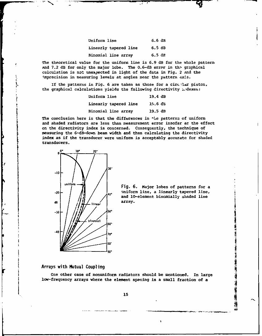
Uniform line 6.6 dB
Linearly tapered line 6.5 dB
Binomial line array 6.5 dE
The theoretical value for the uniform line is 6.9 dB for the whole patternand 7.2 dB for only the major lobe. The 0.6-dB error in th,- graphicalcalculation is not unexpected in light of the data in Fig. 2 and theimprecision in measuring levels at angles near the pattern ex-s.
If the patterns in Fig. 6 are taken as those for a circ-l. r piston,the graphical calculations yields the following directivity 1.-dexes:
Uniform line 19.4 dB
Linearly tapered line 1#..6 db
Binomial line array 19.5 dB
The conclusion here is that the differences in -he patterns of uniformand shaded radiators are less than measurement error insofar a! the effecton the directivity index is concerned. Consequently, the technique ofmeasuring the 6-dB-down beam width and then calculating the directivityindex as if the transducer were uniform is acceptably accurate for shadedtransducers.
•0 O 10 . 20 "
30'-10
Sf 0 Fig. 6. Major lobes of patterns for a
20 -40. un m line, a linearly tapered line,and l-element binomially shaded line
i8 array.
' 'I
-40 70
80'
Arrays with Mutual Coupling
One other case of nonuniform radiators should be mentioned. In largelow-frequency arrays where the element spacing is a small fraction of a
15

wavelength, there is mutual interaction or coupling among the elements.That is, the radiation impedarce of one element is affected by the vibra-tion of neighboring elements. The elements usually are vibrating at theirresonance frequency and thus are sensitive to any effect on their radiationimpedance. The result can be nonuniform vibration zmong the elements dueto this mutual coupling, which would inva) idate the directivity indexcomputation based on uniform pistons or lines. As in the case of shadedtransducers, it becomes a questton of wh :ther the measurea pattern is simi-lar enc.ugh to that of an eqi.ivlent uniform array. Unlike shading, mutualcoupling i,- an unintentional and undesliable effect. When a pattern issignificcntly affected by mutual coupling, the problem usually is that ofcorrecting t!7e cause rathe: than measuring dhe result.
ConclusionFrom both experiment and theory, it is apparent that the directivity
index of any ordinary transducer can be obtained from calculations basedon known configuration and dimensions or beam-width measurements with adegree of reliability and accuracy that is no worse than any measurementtechnique. A ccnservative limit for the validity of such calculations isthat the minimum trans' rr dimension be one wavelength.
Acknr,. cigementThe author is indebted to James D. George for computer calculations
used in this study.
References
[I) H. Stenzel, Leitfaden zua Berecimung von SchazZvorgilr4en (JuliusSpringer, Berlin, 1939); also republished by J. W. Edwards in 1944in the United States under the authority of Alien Property Custo-dian License No. A-491.
[21 C. T. Xolloy, "Calculation of the Directivity Index for Various Typesof Radiators," J. Acoust. Soc. Am. 20, 387-405 (1948).
[3] P. M. Kendig and R. E. Mueser, "A Simplified Method for DeterminingTransducer Directivity Index," J. Acoust. Soc. Am. 19, 691-694 (1947).
[4] C. E. Green and J. R. Roshon, "Directivity Factor Cooputer for Elec-troacoustic Transducers," NEL Report 1196, U. S. Navy ElectronicsLaboratory. San Diego, California, 13 Sep 1963.
16

[5] Scientific-Atlanta, Inc. is the manufacturer of equipment for inte-grating the patterns of both sonar transducers and antennas.
[61 A. M. Young, "Digital System for the Measurement of DirectivityIndex," NRL Report 7585, 20 Apr 1973 [AD-758 639].
[7] R. F. Green, "Measuring the Directivity Index of Underwater SoundProjectors," IEEE Trans. on Audio and Electroacoustics AU-21, 407-412(1973).
[8' R. J. dobber, Undera•ater Etectroacoustic Measurements (Naval ResearchLaboratory, U. S. Government Printing Office, Washington, D. t.,
1970), plt. 83-90.
19] Special slide rules for calculating sonar transducer parameters havebeen pro.uced by the Edo Corporation, Sperry-Rand, and The RaytheonCorp.
[10] H. Stenzel, Guide for the Calculation of Sound Processes, NAVSHIPS250-940; translation of reference 1 by C. E. Mongan, Jr., May 1947.
[11i H. Stenzel, Handlbook for the CaculZation of Sound PropagationPhenomena, NRL Translation 130 by A. R. Stickley, Nov 1947 [trans-lation of reference 1 into English].
[12] H. Stenzel and 0. Brosze, Leitfaden zur Berechnuna von Schaiiiorgngen,Zweite Auflage (Springer-Verlag, Berlin, 1958) [a second edition ofreference 1, in German, by Brosze after Stenzel's death].
[13] Reference 8, pp. 89-90.
[14] B. G. Watters, "A Reverberant Tank for Underwater Measurements,"J. Acoust. Soc. Am. 53, 357(A) .1973) [Paper 114, 84th Meetingof the Acoustical Society of America, Nov 1972].
[15] A. E. Reznikov and A. Ya. Snytko, "Problem of Measuring the AxialConcentration Coefficient in Ultrasonic Radiators," MeasurementTecnniques (the Soviet Journal Izmerte 'nag-a 2ekhnika in English
translation], No. 7, July 1965, pp. 654-657.
[16] L. L. Beranek, Acoustics (McGraw-Hill Book Co., New York, 1954),p. 112.
[17] H. Stenzel, "Remarks on a Paper entitled 'Calculation of the Direc-tivity Index for Various Types of Radiators,'" J. Acoust. Soc. Am. 24,
147-418 (1952).
[18] R. J. Bobber, "The Effects of Element Packing on the Ccmplete Radia-tion Patterns of Arrays," NRL Memorandum Report 2206, 18 Jan 1971[AD-718 3121.
[19] R. J. Bobber, "Diffraction Constants of Transducers," J. Acoust.soc. Am. 37, 591-595 (1965).
[20] T. A. Henriquez, "Diffraction Constants of Acoustic Transducers,"S3. Acoust. Soc. Am. 36, 267-269 (1964).
[21] American National Standard, "Procedures for Calibration of Under- _4water Electroacoustic Transducers," ANSI S1.20-1972, p. 27.
17
-~ It_