distributed energy communications & controls (decc ... 2010 peer review... · distributed...
TRANSCRIPT

Evolved from 1943 Manhattan Project
Distributed Energy Communications & Controls (DECC) Laboratory Activities
Presented by D. Tom Rizy
John Kueck, Fran Li, Yan Xu, Phil Irminger1
ORNL
Huijuan Li, Sarina AdhikariUniversity of Tennessee
1Oak Ridge Associated Universities

2 Managed by UT-Battellefor the U.S. Department of Energy
DECC Laboratory is interfaced with ORNL owned and operated distribution system
DECC Lab

3 Managed by UT-Battellefor the U.S. Department of Energy
DECC Laboratory (2 locations) is located on the North ORNL Campus
DECC Lab
DECC Annex
50kW PV Array is connected to the DECC Lab
PV Array

DECC Laboratory’s Four Test Systems
Inverter–based DR Test SystemRotating-Based DR (SC) Test System
Air Conditioning Stall Test System Remote Large Inverter-based DR Test System

5 Managed by UT-Battellefor the U.S. Department of Energy
DECC Lab Relevance to Smart Grid 2030
One of the Smart Grid 2030 Targets*• 20% of electricity capacity from distributed and renewable energy sources
– 200 GW of DR and Renewables– Demonstrate fast voltage regulation and overvoltage protection solutions under high
penetration of renewable energy by 2014
• DECC Focus– Autonomous Control - develop independent, adaptive, and scalable control of DR– Develop rapid local control methods for providing non-active as well as active power – Use minimal communications – additional functionality is possible when it is present
*Per Smart Grid R&D 2010-2014 MYPP, U.S Department of Energy, Office of Electricity Delivery & Energy Reliability.

6 Managed by UT-Battellefor the U.S. Department of Energy
Approach - Inverter-based Test SystemObjective: Develop, simulate, and verify with testing autonomous, adaptive controls for inverter-based distributed energy resource (DR) when there are multiple inverters on the same feeder or electrically close.

7 Managed by UT-Battellefor the U.S. Department of Energy
ApproachInverter Control Methodology, Fixed vs. Adaptive
Power System(Controlled System)
VoltageReference ControllerCompare
Error
Voltage(Controlled Variable)
Measure
vc
DR: Distributed Energy ResourceControl variable: the PCC voltageReference: the desired value of the
PCC voltageError: difference between reference
and measured PCC voltage
• Fixed control: PI control with Kp and Ki fixedKp and Ki typically by trial & errorIncorrect gains result in under-performance, oscillation, or instability
• Adaptive control:Kp and Ki values are initially conservative but adjusted in real-time to achieve desired system response timeVoltage stability is ensured
Load
Controller
ic vdc
switchingsignals
vt(PCC)is il
Lc
ic
vc
isvt
vdc
il
Ls Rsvs
DEDR

8 Managed by UT-Battellefor the U.S. Department of Energy
Technical Accomplishments of Inverter-based Controls
• Development of adaptive controls for multiple inverter-based DRs– Adaptive voltage regulation controls have been further enhanced.– New active (P) and nonactive (Q) power control for controlling P and Q power independently has
been developed and is being further refined.
• Simulation of multiple inverter-based DR controls on the model of the ORNL system– Adaptive voltage regulation controls have been tested on a system similar to the ORNL system
and IEEE system models.
• Testing of multiple test systems with our adaptive controls– A second large inverter-based test system is being completed we have tested controls
simultaneously on our rotating and inverter based DR test systems.– Expect to have second inverter system operational by year end but simulation of two inverter
based systems indicates potential interaction.
• Implementation of the adaptive controls in a microcontroller (DSP) at one of the inverter test systems and repeat the multiple inverter testing– Focused on a new method for inverter “soft-engagement” to grid due to dc voltage sensitivity.– Microprocessor (DSP) control test setup and will be tested at an inverter system in FY11.
9 Managed by UT-Battellefor the U.S. Department of Energy
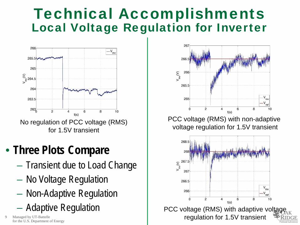
Technical AccomplishmentsLocal Voltage Regulation for Inverter
• Three Plots Compare– Transient due to Load Change– No Voltage Regulation– Non-Adaptive Regulation– Adaptive Regulation
PCC voltage (RMS) with non-adaptive voltage regulation for 1.5V transient
PCC voltage (RMS) with adaptive voltage regulation for 1.5V transient
No regulation of PCC voltage (RMS)for 1.5V transient

10 Managed by UT-Battellefor the U.S. Department of Energy
Technical AccomplishmentsIndependent Active & Non-Active Power Control
• Complete event on left.
• Zoomed in to 10 to 20 kW change on right.
• Active power reference (Pref) from 10 to 50kW.
• Nonactive power reference (Qref) set to10 kVar.
• P does not reach 50 kW and Q drops because of the inverter current limit (60A).
Qref set to10kVar.
Pref change from 10 to 20kWPref changed from 10 kW to 50 kW
Qref set to10kVar.

11 Managed by UT-Battellefor the U.S. Department of Energy
DECC Laboratory Air Conditioning (A/C)Voltage Stall Relevance
Challenge: Air conditioning stall can occur rapidly and result in high reactive current demand and is a significant challenge to mitigate with DR alone.
• Reduced Capacity– High penetration A/C stalling causes
4-5 times normal current– Increases reactive power demand of
the distribution system and can reduce available capacity.
• Degraded Power Quality & Reliability– A/C units can stall in 3 cycles (0.05s)
following a sub-transmission fault– Stall can last for 30s resulting in an
extended voltage sag event (FIDVR).
• Reduced Energy Efficiency – Increased current of the stalled A/C
units can result in 16-25 times the normal current losses.
• Present Operational Problems– Volt/Var control is a major concern
when an A/C stall event occurs.– FIDVR can result in a microvoltage
collapse in the distribution system.– Ultimately could result in transmission
system voltage instability and even voltage collapse.
Areas of Impact

12 Managed by UT-Battellefor the U.S. Department of Energy
ApproachAir Conditioning (A/C) Stall Test System
Objective: Explore impact of high penetration high seasonal energy efficiency ratio (SEER) air conditioning (A/C) units on power systems during sub-transmission faults.
13 Managed by UT-Battellefor the U.S. Department of Energy
Technical Accomplishments
• Testing System - Completed the A/C Stall Test System– New test system at the DECC Laboratory.
• Model - Complete composite load and motor model for EMTP– Dynamic model for the A/C compressor operation during normal voltage and stalled voltage was
developed.– Analysis using the model was completed and a technical paper was presented/published.
• Testing – Fine-tune the model with results from A/C Stall testing– A/C stall characterization of sustained voltage sags; response too slow for fault response.– Completed installation of a fast contactor/switch to implement momentary sags characterization..– Model for specific heat pump model still undergoing development based on manufacturer specs, test data
and ORNL heat pump design (thermodynamic) model.
• System Impacts – Impact of high penetration high SEER A/C– Impact on distribution system – initial analysis using the hybrid air conditioner compressor model but plan
revisit with specific heat pump model.– Impact on transmission system voltage stability - Have a large systems model built in EMTP that will be
used and developed a approach.

14 Managed by UT-Battellefor the U.S. Department of Energy
Technical AccomplishmentsA/C Stall Characterization Results
• Sustained Voltage Sag
Voltage Sag of 52% for 0.08s (~1 cycle)Voltage Recovery takes 0.47s (~7.5 cycles)
Normal Current = 13.5AStalled Current = 105A, 8 times normal
Heat Pump only recovers 50% of the Time
• Momentary Voltage Sag
Normal Current = 13.5AStalled Current = 46 to 40A, ~3.4 to 3 times
Voltage Sag of 55% for ~250s
Thermal Overload Trip
Thermal Overload Trip
15 Managed by UT-Battellefor the U.S. Department of Energy
Technology Transfer & Collaborations
• DECC Industry Team– SCE provided initial air conditioning stall test data, report on SEER (10 to 13) units and data for
Catalina Island power system.– SCE, TVA & LCUB provided valuable input on their system voltage regulation requirements for
adaptive inverter controls.
• IEEE Volt-Var Control Task Force (VVCTF)– Formed January 2010 by the IEEE PES Distribution Subcommittee and industry is showing
great interest (Tom Rizy is Chair).
• NERC– ORNL (Kueck, Dimitrovski) on VAR working group which was assembled from FERC
recommendations and hosted 2nd meeting at ORNL
• EETN & KUB– Negotiating collaboration agreement with Efficient Energy of Tennessee and Knoxville Utilities
Board to implement ORNL adaptive controls at their 1MW PV system.

16 Managed by UT-Battellefor the U.S. Department of Energy
Conclusions
• DECC activities are addressing voltage problems by extending the functionality of DR, specifically inverter-based systems.
• DECC Lab is a unique testing environment interfaced to an actual distribution system and provides a real-world testing environment.– Additional inverter systems need to be considered for A/C stall.– Multiple inverter operation interaction and with NIST modes need to be considered.
• Advanced control algorithms have been developed, simulated and verified with testing at the DECC Lab and published.
• Control methods provide a rapid dynamic voltage regulation or active & non-active power regulation by inverter-based DR.
• Local voltage/var regulation is a practical method for expanding the margin-to-local voltage collapse and for providing local power quality.

17 Managed by UT-Battellefor the U.S. Department of Energy
Selected Publications
“Instantaneous Active and Nonactive Power Control of Distributed Energy Resources with a Current Limiter”, Paper #464, Session 110: Sustainable Energy Applications: Flexible Renewable/Alternative Energy System II, 2010 IEEE Energy Conversion Congress & Exposition (ECCE), Atlanta, GA, Sep. 2010.
"Adaptive Voltage Control with Distributed Energy Resources: Algorithm, Theoretical Analysis, Simulation, and Field Test Verification,“ IEEE Transactions on Power Systems, Vol.25, No.3, pp.1638-1647, Aug. 2010, http://ieeexplore.ieee.org/stamp/stamp.jsp?tp=&arnumber=5431066&isnumber=5512898.
"Properly Understanding the Impacts of Distributed Resources on Distribution Systems," 2010 IEEE Power and Energy Society General Meeting, pp.1-5, July 2010, http://ieeexplore.ieee.org/stamp/stamp.jsp?tp=&arnumber=5589726&isnumber=5588047.
"Local Voltage Support from Distributed Energy Resources to Prevent Air Conditioner Motor Stalling," 2010Innovative Smart Grid Technologies (ISGT), pp.1-6, Jan. 2010, http://ieeexplore.ieee.org/stamp/stamp.jsp?tp=&arnumber=5434728&isnumber=5434721.
"An Adaptive Voltage Control Algorithm with Multiple Distributed Energy Resources," 2009 North American Power Symposium (NAPS), pp.1-6, Oct. 2009, http://ieeexplore.ieee.org/stamp/stamp.jsp?tp=&arnumber=5484035&isnumber=5483979.
"Preventing delayed voltage recovery with voltage-regulating distributed energy resources," IEEE PowerTech 2009, Bucharest, pp.1-6, June-July 2009, http://ieeexplore.ieee.org/stamp/stamp.jsp?tp=&arnumber=5281866&isnumber=5281781.

Evolved from 1943 Manhattan Project
Q&A

19 Managed by UT-Battellefor the U.S. Department of Energy
OAK RIDGE NATIONAL LABORATORYManaged By UT-Battelle for the Department of Energy
D. Tom Rizy, Research StaffPower & Energy Systems GroupEnergy & Transportation Science DivisionOne Bethel Valley Road, MS-6070Oak Ridge, Tennessee 37831-6070
(865) 574-5203 Voice, 9338 Fax(865) 207-6769 CellEmail: [email protected], www.ornl.gov/sci/decc