distributed i/o device et 200m
TRANSCRIPT
SIMATIC Distributed I/O device ET 200M
________________________________________________________________________________________________________________________________________________________________________
Preface
Product overview 1
Brief instructions on commissioning
2
Assignment planning 3
Installation 4
Connecting 5
Commissioning 6
Maintenance and service 7
Functions 8
Interrupt, error and system messages
9
Technical Specifications 10
Compatibilities between the IM 153-x
AOrder Numbers for the ET 200M
B
SIMATIC
Distributed I/O device ET 200M
Operating Instructions
02/2006 EWA-4NEB7806006-02 07
The following supplement is part of this documentation:
No. Product Information Drawing number Edition
1 Redundant mode of the ET 200M on a S7-400H
A5E01054779-01 01/2007
2 Interface Module IM 153-4 PN A5E01047033-01 04/2007
3 ET 200M IM 153-2 Interface Module
A5E01208335-01 08/2007
Safety Guidelines This manual contains notices you have to observe in order to ensure your personal safety, as well as to prevent damage to property. The notices referring to your personal safety are highlighted in the manual by a safety alert symbol, notices referring only to property damage have no safety alert symbol. These notices shown below are graded according to the degree of danger.
Danger
indicates that death or severe personal injury will result if proper precautions are not taken.
Warning
indicates that death or severe personal injury may result if proper precautions are not taken.
Caution
with a safety alert symbol, indicates that minor personal injury can result if proper precautions are not taken.
Caution
without a safety alert symbol, indicates that property damage can result if proper precautions are not taken.
Notice
indicates that an unintended result or situation can occur if the corresponding information is not taken into account.
If more than one degree of danger is present, the warning notice representing the highest degree of danger will be used. A notice warning of injury to persons with a safety alert symbol may also include a warning relating to property damage.
Qualified Personnel The device/system may only be set up and used in conjunction with this documentation. Commissioning and operation of a device/system may only be performed by qualified personnel. Within the context of the safety notes in this documentation qualified persons are defined as persons who are authorized to commission, ground and label devices, systems and circuits in accordance with established safety practices and standards.
Prescribed Usage Note the following:
Warning
This device may only be used for the applications described in the catalog or the technical description and only in connection with devices or components from other manufacturers which have been approved or recommended by Siemens. Correct, reliable operation of the product requires proper transport, storage, positioning and assembly as well as careful operation and maintenance.
Trademarks All names identified by ® are registered trademarks of the Siemens AG. The remaining trademarks in this publication may be trademarks whose use by third parties for their own purposes could violate the rights of the owner.
Disclaimer of Liability We have reviewed the contents of this publication to ensure consistency with the hardware and software described. Since variance cannot be precluded entirely, we cannot guarantee full consistency. However, the information in this publication is reviewed regularly and any necessary corrections are included in subsequent editions.
Siemens AG Automation and Drives Postfach 48 48 90437 NÜRNBERG GERMANY
Order No.: EWA-4NEB7806006-02 07 02/2006
Copyright © Siemens AG 2006. Technical data subject to change
ET 200M Operating Instructions, 02/2006, EWA-4NEB7806006-02 07 iii
Preface
Purpose of the operating instructions The information contained in these operating instructions enables you to operate an IM 153 interface module together with the modules of the S7-300 spectrum in the distributed I/O ET 200 as a DP slave.
Basic knowledge required To understand the operating instructions, you require general experience in the field of automation engineering.
Scope of the operating instructions
Module Order number As of product version 6ES7153-1AA03-0XB0 02 IM 153-1 6ES7153-1AA83-0XB0 01 6ES7153-2AA02-0XB0 07 6ES7153-2BA00-0XB0 01 6ES7153-2BA01-0XB0 01
IM 153-2
6ES7153-2BA81-0XB0 01 6ES7153-2AB01-0XB0 06 IM 153-2 FO 6ES7153-2BB00-0XB0 01
Declaration: In the following the term IM 153-x is used in the operating instructions, apart from when a description refers directly to a special variant of the IM 153-x. A variant of the IM 153-1 as well as of the IM 153-2 is also available as a module for use in expanded environmental conditions ("outdoor"). To find out under which climatic and mechanical environmental conditions you can use the IM 153-1/-2, refer to the S7-300 Automation System, Module Data manual. With the IM 153-x in the latest version we reserve the right to enclose a product information bulletin containing up-to-date information regarding new components for the respective IM 153-x interface module or the operating instructions. You´ll also find this product information in the Internet under the address http://support.automation.siemens.com There, search for e.g. "IM 153-2".
Preface
ET 200M iv Operating Instructions, 02/2006, EWA-4NEB7806006-02 07
Changes since the previous version The following changes have been made since the previous version of these operating instructions ET 200M distributed I/O device with the drawing number EWA-4NEB780600601-06, version 10/2002: The IM 153-2Bxx1 interface module as of the abovementioned versions offers the following new functions: • automatic detection of the configuration variant (ET 200M or DP/PA link or Y link) • highly precise time stamp with 1 ms precision • Time stamp outside of S7-400 • Clock synchronization on the I/O bus • Flying redundancy in accordance with standards
specification slave redundancy V1.2, Nov. 2004 of the PROFIBUS user organization; order no: 2.212
• optimized isochrone mode with overlapping of Ti and To • identification and maintenance data (I&M data) • direct data exchange with F-modules • update of redundant IM 153-2 via PROFIBUS DP during running operation • adding error types in the channel-related diagnostics In the Compatibilities appendix the overviews show with which functions or properties the interface module IM 153-x is compatible with its predecessor versions.
Approvals See chapter Technical Specifications > Standards and Approvals.
CE Label See chapter Technical Specifications > Standards and Approvals.
Identification for Australia (C-tick mark) See chapter Technical Specifications > Standards and Approvals.
Standards See chapter Technical Specifications > Standards and Approvals.
Preface
ET 200M Operating Instructions, 02/2006, EWA-4NEB7806006-02 07 v
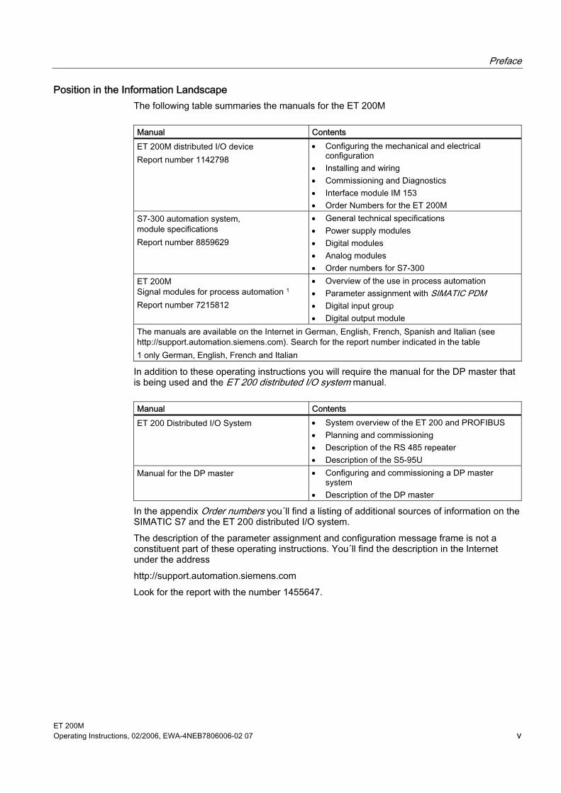
Position in the Information Landscape The following table summaries the manuals for the ET 200M
Manual Contents ET 200M distributed I/O device Report number 1142798
• Configuring the mechanical and electrical configuration
• Installing and wiring • Commissioning and Diagnostics • Interface module IM 153 • Order Numbers for the ET 200M
S7-300 automation system, module specifications Report number 8859629
• General technical specifications • Power supply modules • Digital modules • Analog modules • Order numbers for S7-300
ET 200M Signal modules for process automation 1 Report number 7215812
• Overview of the use in process automation • Parameter assignment with SIMATIC PDM • Digital input group • Digital output module
The manuals are available on the Internet in German, English, French, Spanish and Italian (see http://support.automation.siemens.com). Search for the report number indicated in the table 1 only German, English, French and Italian
In addition to these operating instructions you will require the manual for the DP master that is being used and the ET 200 distributed I/O system manual.
Manual Contents ET 200 Distributed I/O System • System overview of the ET 200 and PROFIBUS
• Planning and commissioning • Description of the RS 485 repeater • Description of the S5-95U
Manual for the DP master • Configuring and commissioning a DP master system
• Description of the DP master
In the appendix Order numbers you´ll find a listing of additional sources of information on the SIMATIC S7 and the ET 200 distributed I/O system. The description of the parameter assignment and configuration message frame is not a constituent part of these operating instructions. You´ll find the description in the Internet under the address http://support.automation.siemens.com Look for the report with the number 1455647.
Preface
ET 200M vi Operating Instructions, 02/2006, EWA-4NEB7806006-02 07
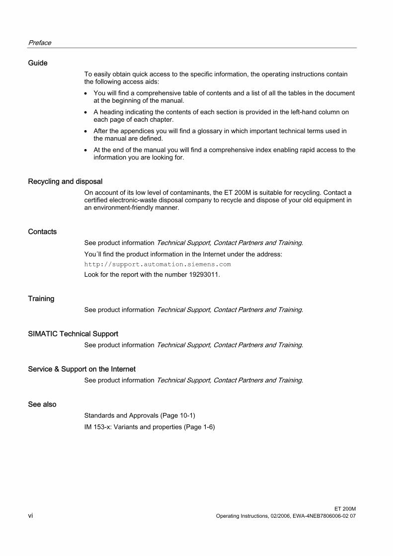
Guide To easily obtain quick access to the specific information, the operating instructions contain the following access aids: • You will find a comprehensive table of contents and a list of all the tables in the document
at the beginning of the manual. • A heading indicating the contents of each section is provided in the left-hand column on
each page of each chapter. • After the appendices you will find a glossary in which important technical terms used in
the manual are defined. • At the end of the manual you will find a comprehensive index enabling rapid access to the
information you are looking for.
Recycling and disposal On account of its low level of contaminants, the ET 200M is suitable for recycling. Contact a certified electronic-waste disposal company to recycle and dispose of your old equipment in an environment-friendly manner.
Contacts See product information Technical Support, Contact Partners and Training. You´ll find the product information in the Internet under the address: http://support.automation.siemens.com Look for the report with the number 19293011.
Training See product information Technical Support, Contact Partners and Training.
SIMATIC Technical Support See product information Technical Support, Contact Partners and Training.
Service & Support on the Internet See product information Technical Support, Contact Partners and Training.
See also Standards and Approvals (Page 10-1) IM 153-x: Variants and properties (Page 1-6)
ET 200M Operating Instructions, 02/2006, EWA-4NEB7806006-02 07 vii
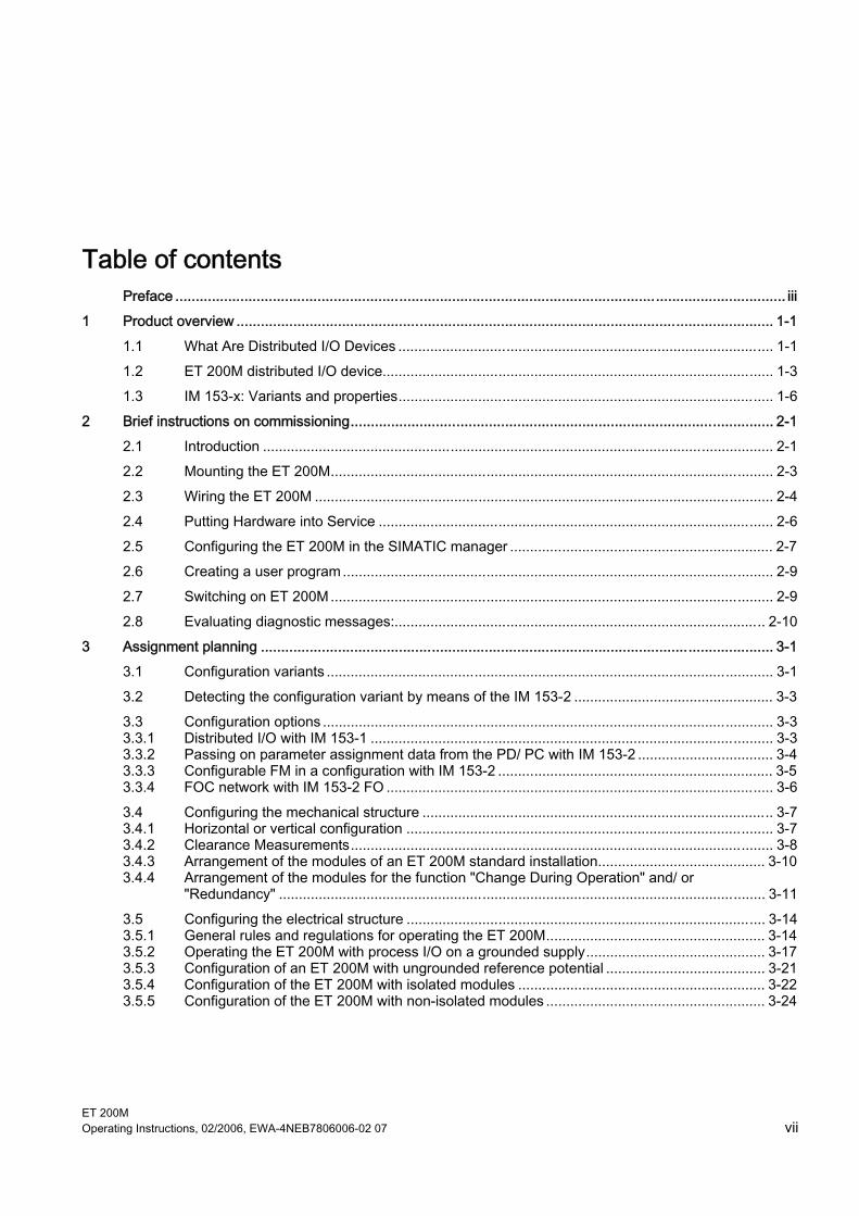
Table of contents Preface ...................................................................................................................................................... iii 1 Product overview .................................................................................................................................... 1-1
1.1 What Are Distributed I/O Devices .............................................................................................. 1-1 1.2 ET 200M distributed I/O device.................................................................................................. 1-3 1.3 IM 153-x: Variants and properties.............................................................................................. 1-6
2 Brief instructions on commissioning........................................................................................................ 2-1 2.1 Introduction ................................................................................................................................ 2-1 2.2 Mounting the ET 200M............................................................................................................... 2-3 2.3 Wiring the ET 200M ................................................................................................................... 2-4 2.4 Putting Hardware into Service ................................................................................................... 2-6 2.5 Configuring the ET 200M in the SIMATIC manager .................................................................. 2-7 2.6 Creating a user program............................................................................................................ 2-9 2.7 Switching on ET 200M............................................................................................................... 2-9 2.8 Evaluating diagnostic messages:............................................................................................. 2-10
3 Assignment planning .............................................................................................................................. 3-1 3.1 Configuration variants ................................................................................................................ 3-1 3.2 Detecting the configuration variant by means of the IM 153-2 .................................................. 3-3 3.3 Configuration options ................................................................................................................. 3-3 3.3.1 Distributed I/O with IM 153-1 ..................................................................................................... 3-3 3.3.2 Passing on parameter assignment data from the PD/ PC with IM 153-2 .................................. 3-4 3.3.3 Configurable FM in a configuration with IM 153-2 ..................................................................... 3-5 3.3.4 FOC network with IM 153-2 FO ................................................................................................. 3-6 3.4 Configuring the mechanical structure ........................................................................................ 3-7 3.4.1 Horizontal or vertical configuration ............................................................................................ 3-7 3.4.2 Clearance Measurements.......................................................................................................... 3-8 3.4.3 Arrangement of the modules of an ET 200M standard installation.......................................... 3-10 3.4.4 Arrangement of the modules for the function "Change During Operation" and/ or
"Redundancy" .......................................................................................................................... 3-11 3.5 Configuring the electrical structure .......................................................................................... 3-14 3.5.1 General rules and regulations for operating the ET 200M....................................................... 3-14 3.5.2 Operating the ET 200M with process I/O on a grounded supply............................................. 3-17 3.5.3 Configuration of an ET 200M with ungrounded reference potential ........................................ 3-21 3.5.4 Configuration of the ET 200M with isolated modules .............................................................. 3-22 3.5.5 Configuration of the ET 200M with non-isolated modules ....................................................... 3-24
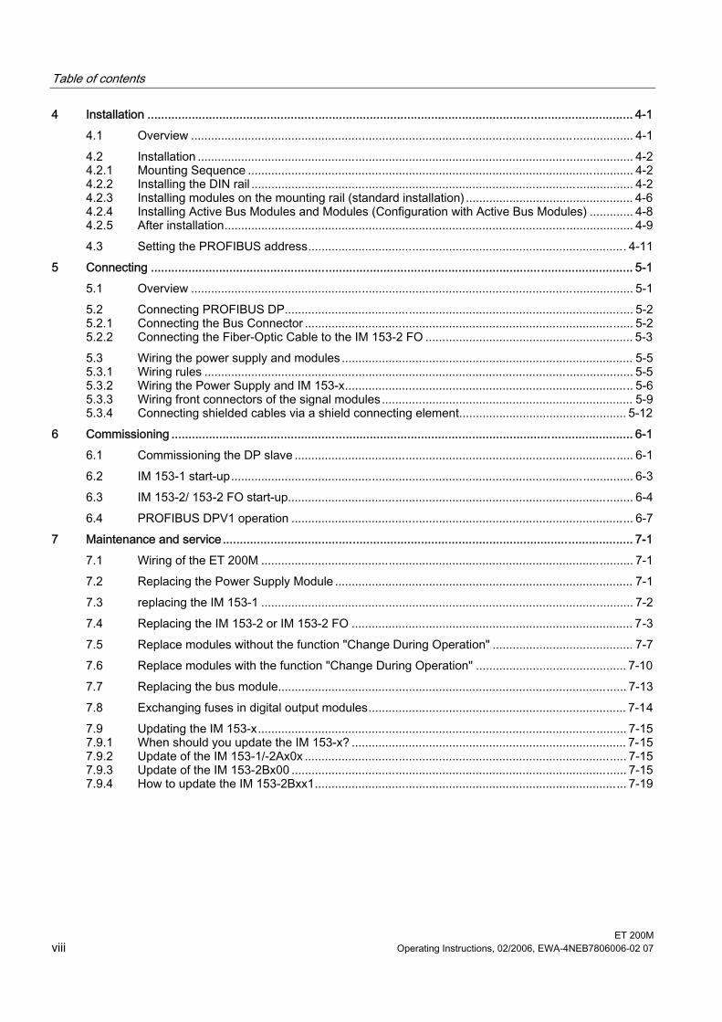
Table of contents
ET 200M viii Operating Instructions, 02/2006, EWA-4NEB7806006-02 07
4 Installation .............................................................................................................................................. 4-1 4.1 Overview .................................................................................................................................... 4-1 4.2 Installation .................................................................................................................................. 4-2 4.2.1 Mounting Sequence ................................................................................................................... 4-2 4.2.2 Installing the DIN rail .................................................................................................................. 4-2 4.2.3 Installing modules on the mounting rail (standard installation) .................................................. 4-6 4.2.4 Installing Active Bus Modules and Modules (Configuration with Active Bus Modules) ............. 4-8 4.2.5 After installation.......................................................................................................................... 4-9 4.3 Setting the PROFIBUS address............................................................................................... 4-11
5 Connecting ............................................................................................................................................. 5-1 5.1 Overview .................................................................................................................................... 5-1 5.2 Connecting PROFIBUS DP........................................................................................................ 5-2 5.2.1 Connecting the Bus Connector .................................................................................................. 5-2 5.2.2 Connecting the Fiber-Optic Cable to the IM 153-2 FO .............................................................. 5-3 5.3 Wiring the power supply and modules ....................................................................................... 5-5 5.3.1 Wiring rules ................................................................................................................................ 5-5 5.3.2 Wiring the Power Supply and IM 153-x...................................................................................... 5-6 5.3.3 Wiring front connectors of the signal modules........................................................................... 5-9 5.3.4 Connecting shielded cables via a shield connecting element.................................................. 5-12
6 Commissioning ....................................................................................................................................... 6-1 6.1 Commissioning the DP slave ..................................................................................................... 6-1 6.2 IM 153-1 start-up........................................................................................................................ 6-3 6.3 IM 153-2/ 153-2 FO start-up....................................................................................................... 6-4 6.4 PROFIBUS DPV1 operation ...................................................................................................... 6-7
7 Maintenance and service........................................................................................................................ 7-1 7.1 Wiring of the ET 200M ............................................................................................................... 7-1 7.2 Replacing the Power Supply Module ......................................................................................... 7-1 7.3 replacing the IM 153-1 ............................................................................................................... 7-2 7.4 Replacing the IM 153-2 or IM 153-2 FO .................................................................................... 7-3 7.5 Replace modules without the function "Change During Operation" .......................................... 7-7 7.6 Replace modules with the function "Change During Operation" ............................................. 7-10 7.7 Replacing the bus module........................................................................................................ 7-13 7.8 Exchanging fuses in digital output modules............................................................................. 7-14 7.9 Updating the IM 153-x.............................................................................................................. 7-15 7.9.1 When should you update the IM 153-x? .................................................................................. 7-15 7.9.2 Update of the IM 153-1/-2Ax0x ................................................................................................ 7-15 7.9.3 Update of the IM 153-2Bx00 .................................................................................................... 7-15 7.9.4 How to update the IM 153-2Bxx1............................................................................................. 7-19
Table of contents
ET 200M Operating Instructions, 02/2006, EWA-4NEB7806006-02 07 ix
8 Functions ................................................................................................................................................ 8-1 8.1 Time stamping the input signals with IM 153-2.......................................................................... 8-1 8.1.1 Principles.................................................................................................................................... 8-1 8.1.2 Functionalities ............................................................................................................................ 8-3 8.1.2.1 Time stamp with 10 ms precision............................................................................................... 8-3 8.1.2.2 Highly precise time stamp with 1 ms precision .......................................................................... 8-4 8.1.2.3 Time synchronization for time stamping .................................................................................... 8-5 8.1.2.4 Time stamping in the redundant system.................................................................................... 8-9 8.1.3 Time stamping within the S7-400............................................................................................. 8-10 8.1.3.1 With STEP 7 in customer applications..................................................................................... 8-10 8.1.3.2 With the PCS 7 system solution............................................................................................... 8-10 8.1.4 Time stamping outside of S7-400 ............................................................................................ 8-12 8.1.4.1 Prerequisites ............................................................................................................................ 8-12 8.1.4.2 Operating principle................................................................................................................... 8-16 8.1.4.3 Brief introduction to commissioning the time stamping ........................................................... 8-18 8.1.4.4 Time synchronization ............................................................................................................... 8-19 8.1.4.5 Configuring the time stamping ................................................................................................. 8-19 8.1.4.6 Structure of the process interrupt............................................................................................. 8-22 8.1.4.7 Structure of the IM 153-2 messages........................................................................................ 8-23 8.1.4.8 Significance of special messages............................................................................................ 8-25 8.1.4.9 Diagnosis for time stamping..................................................................................................... 8-27 8.2 Clock synchronization on the I/O bus ...................................................................................... 8-29 8.3 Redundancy with IM 153-2 ...................................................................................................... 8-30 8.4 System modification during operation...................................................................................... 8-33 8.4.1 System modification in a non-redundant system..................................................................... 8-34 8.4.2 System modification in a redundant system ............................................................................ 8-34 8.5 Isochrone mode ....................................................................................................................... 8-36 8.5.1 What is Isochronous? .............................................................................................................. 8-36 8.5.2 Configuring the isochrone mode.............................................................................................. 8-39 8.6 Identification and maintenance data (I&M data) ...................................................................... 8-43 8.7 Direct data exchange ............................................................................................................... 8-47 8.8 Direct data exchange with F modules (fail-safe I slave-slave communication) ....................... 8-48
9 Interrupt, error and system messages .................................................................................................... 9-1 9.1 Diagnostics with LED display..................................................................................................... 9-1 9.2 Diagnosis with STEP 7 or STEP 5............................................................................................. 9-6 9.3 Structure of the diagnosis .......................................................................................................... 9-8 9.3.1 Structure of slave diagnosis....................................................................................................... 9-8 9.3.2 Station statuses 1 to 3 ............................................................................................................. 9-10 9.3.3 Master PROFIBUS address..................................................................................................... 9-11 9.3.4 Manufacturer ID ....................................................................................................................... 9-12 9.3.5 Evaluating the slave diagnosis................................................................................................. 9-12 9.3.6 Identifier-related diagnosis....................................................................................................... 9-13 9.3.7 Module status........................................................................................................................... 9-14 9.3.8 Channel-specific diagnostics ................................................................................................... 9-15 9.3.9 H status (only with S7-400 H and normal redundancy) ........................................................... 9-20 9.3.10 Interrupts .................................................................................................................................. 9-21 9.3.11 Evaluating interrups from station diagnosis ............................................................................. 9-31
Table of contents
ET 200M x Operating Instructions, 02/2006, EWA-4NEB7806006-02 07
10 Technical Specifications ....................................................................................................................... 10-1 10.1 Standards and Approvals......................................................................................................... 10-1 10.2 Parameters of the IM 153-x...................................................................................................... 10-5 10.3 Technical specifications of the IM 153-x .................................................................................. 10-6 10.4 Time delay of the ET 200M...................................................................................................... 10-9 10.5 Using the ET 200M in the potentially explosive area zone 2 ................................................. 10-10
A Compatibilities between the IM 153-x .....................................................................................................A-1 A.1 Compatibilities between the versions of IM 153 and IM 153-1 ..................................................A-1 A.2 Compatibilities between the versions of IM 153-2/-2 FO ...........................................................A-3 A.3 RC Network with 1 MΩ for Configuration with ungrounded reference potential ........................A-6
B Order Numbers for the ET 200M.............................................................................................................B-1 Glossary ..................................................................................................................................... Glossary-1 Index................................................................................................................................................ Index-1
Tables
Table 1-1 ET 200M components ................................................................................................................ 1-4 Table 1-2 Properties and functions of the IM 153-x variants ..................................................................... 1-6 Table 3-1 ET 200M structure variants in the non-outdoor area ................................................................. 3-1 Table 3-2 ET 200M structure variants in the outdoor area......................................................................... 3-2 Table 3-3 Compatible versions of the IM 153-2 interface module ........................................................... 3-11 Table 3-4 DIN VDE-directives for the configuration of a controller .......................................................... 3-17 Table 4-1 Fixing holes for rails ................................................................................................................... 4-4 Table 4-2 Module accessories ................................................................................................................... 4-6 Table 4-3 Installing modules on mounting rails.......................................................................................... 4-7 Table 4-4 Slot numbers for S7 modules..................................................................................................... 4-9 Table 5-1 Wiring rules for the power supply and the IM 153-x .................................................................. 5-5 Table 5-2 Wiring rules for front connectors of modules ............................................................................. 5-6 Table 5-3 Wiring the Front Connector ...................................................................................................... 5-10 Table 5-4 Preparing the Signal Module for Operation.............................................................................. 5-11 Table 5-5 Assignment of cable cross-sections and terminal elements .................................................... 5-12 Table 6-1 Software prerequisites for commissioning ................................................................................. 6-1 Table 6-2 Compare the DPV1 and DPV0 slave ......................................................................................... 6-7 Table 7-1 Response of the ET 200M when removing or inserting modules ............................................ 7-12 Table 7-2 Available SIMATIC Micro Memory Cards for an update of the IM 153-2................................. 7-17 Table 8-1 Contents of the diagnostic frame (example) ............................................................................ 8-22 Table 8-2 Contents of the interrupt section (example) ............................................................................. 8-22 Table 8-3 Status of time stamping............................................................................................................ 8-23
Table of contents
ET 200M Operating Instructions, 02/2006, EWA-4NEB7806006-02 07 xi
Table 8-4 Return value on DS_READ...................................................................................................... 8-23 Table 8-5 Header data of the IM 153-2 message frame (example)......................................................... 8-23 Table 8-6 Structure of the signal message .............................................................................................. 8-24 Table 8-7 Structure of a special message................................................................................................ 8-24 Table 8-8 Structure of a time stamp in the ISP format............................................................................. 8-25 Table 8-9 DS 248 configuration for the ET 200M .................................................................................... 8-44 Table 8-10 Data record structure with I&M data ........................................................................................ 8-45 Table 8-11 Configuration of the I&M-data .................................................................................................. 8-45 Table 8-12 Conditions for a fail-safe I slave-slave communication............................................................ 8-48 Table 9-1 Status and error displays of the IM 153-1.................................................................................. 9-1 Table 9-2 Status and error displays of the IM 153-2.................................................................................. 9-2 Table 9-3 Reading the diagnosis with STEP 7 and STEP 5 ...................................................................... 9-6 Table 9-4 Structure of station status 1 (Byte 0) ....................................................................................... 9-10 Table 9-5 Structure of station status 2 (Byte 1) ....................................................................................... 9-11 Table 9-6 Structure of station status 3 (Byte 2) ....................................................................................... 9-11 Table 9-7 Structure of the manufacturer ID (Bytes 4, 5) .......................................................................... 9-12 Table 9-8 Error type of the channel-specific diagnosis in accordance with the PROFIBUS standard .... 9-17 Table 9-9 Error type of the channel-specific diagnostic - manufacturer-specific ..................................... 9-18 Table 10-1 Use in industry ......................................................................................................................... 10-3 Table 10-2 Parameters of the IM 153 x...................................................................................................... 10-5 Table 10-3 Parameters for time stamping.................................................................................................. 10-5 Table 10-4 Parameters for clock synchronism........................................................................................... 10-6 Table A-1 Properties and variants of the IM 153-1.....................................................................................A-1 Table A-2 Restrictions for DP master CPUs and FM for IM 153-2.............................................................A-4 Table B-1 ET 200M components................................................................................................................B-1 Table B-2 Manuals on STEP 7 and SIMATIC S7.......................................................................................B-2 Table B-3 Manual for the ET 200 in SIMATIC S5 ......................................................................................B-3 Table B-4 Technical Literature ...................................................................................................................B-3

Table of contents
ET 200M xii Operating Instructions, 02/2006, EWA-4NEB7806006-02 07
ET 200M Operating Instructions, 02/2006, EWA-4NEB7806006-02 07 1-1
Product overview 11.1 1.1 What Are Distributed I/O Devices
Area of application When a system is set up, it is common for the inputs to and outputs from the process to be incorporated centrally in the automation system. If there are inputs and outputs at considerable distances from the programmable controller, there may be long runs of cabling which are not easy to follow, and electromagnetic interference may impair reliability. Distributed I/O devices are the ideal solution for such systems: • the control CPU is located at a central location • The I/O devices (inputs and outputs) operate locally on a distributed basis. • the powerful PROFIBUS DP with high data transmission speed ensures that the control
CPU and the I/O devices communicate smoothly.
What is PROFIBUS DP? PROFIBUS DP is an open bus system in accordance with the standard IEC 61784-1:2002 Ed1 CP 3/1 with the transmission protocol "DP" (DP is the abbreviation of the German term "dezentrale Peripherie" (distributed I/O). Physically, the PROFIBUS DP is either an electric network based on a shielded two-wire line (RS 485) or an optical network based on a fiber-optic cable (FOC). The transmission protocol "DP enables a fast, cyclic data exchange between the control CPU and the distributed I/Os.
What are the DP master and DP slaves? The DP master is the connecting link between the control CPU and the distributed I/Os. The DP master exchanges the data via the PROFIBUS DP with the distributed I/Os and monitors the PROFIBUS DP. The distributed I/Os (= DP slaves) prepare the data of the encoder and the actuators on site in such a way that they can be transmitted via the PROFIBUS DP to the control CPU.
Product overview 1.1 What Are Distributed I/O Devices
ET 200M 1-2 Operating Instructions, 02/2006, EWA-4NEB7806006-02 07
Which devices can be connected to PROFIBUS DP? The most varied devices can be connected as DP masters or DP slaves to the PROFIBUS DP, the only proviso is that they behave in accordance with the standard IEC 61784-1:2002 Ed1 CP 3/1. Among others, devices of the following product families can be used: • SIMATIC S7/ M7/ C7 • SIMATIC S5 • SIMATIC PD/ PC • SIMATIC HMI (operator panel (OP), operator station (OS), and text display (TD) operator
control and monitoring devices) • Devices from other manufacturers
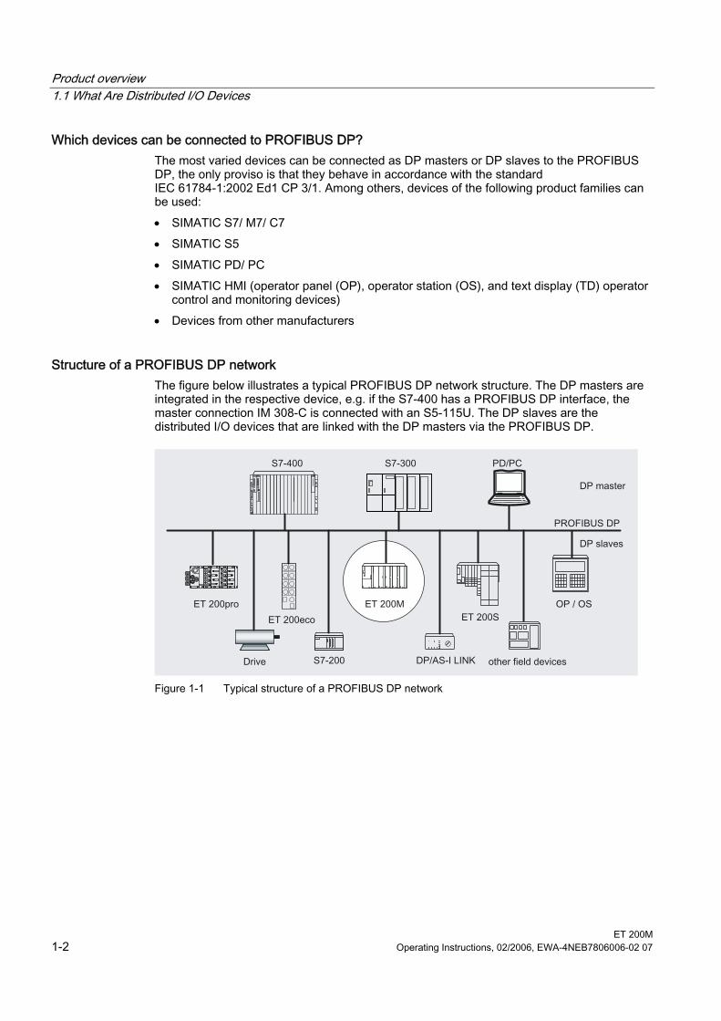
Structure of a PROFIBUS DP network The figure below illustrates a typical PROFIBUS DP network structure. The DP masters are integrated in the respective device, e.g. if the S7-400 has a PROFIBUS DP interface, the master connection IM 308-C is connected with an S5-115U. The DP slaves are the distributed I/O devices that are linked with the DP masters via the PROFIBUS DP.
Figure 1-1 Typical structure of a PROFIBUS DP network
Product overview 1.2 ET 200M distributed I/O device
ET 200M Operating Instructions, 02/2006, EWA-4NEB7806006-02 07 1-3
1.2 1.2 ET 200M distributed I/O device
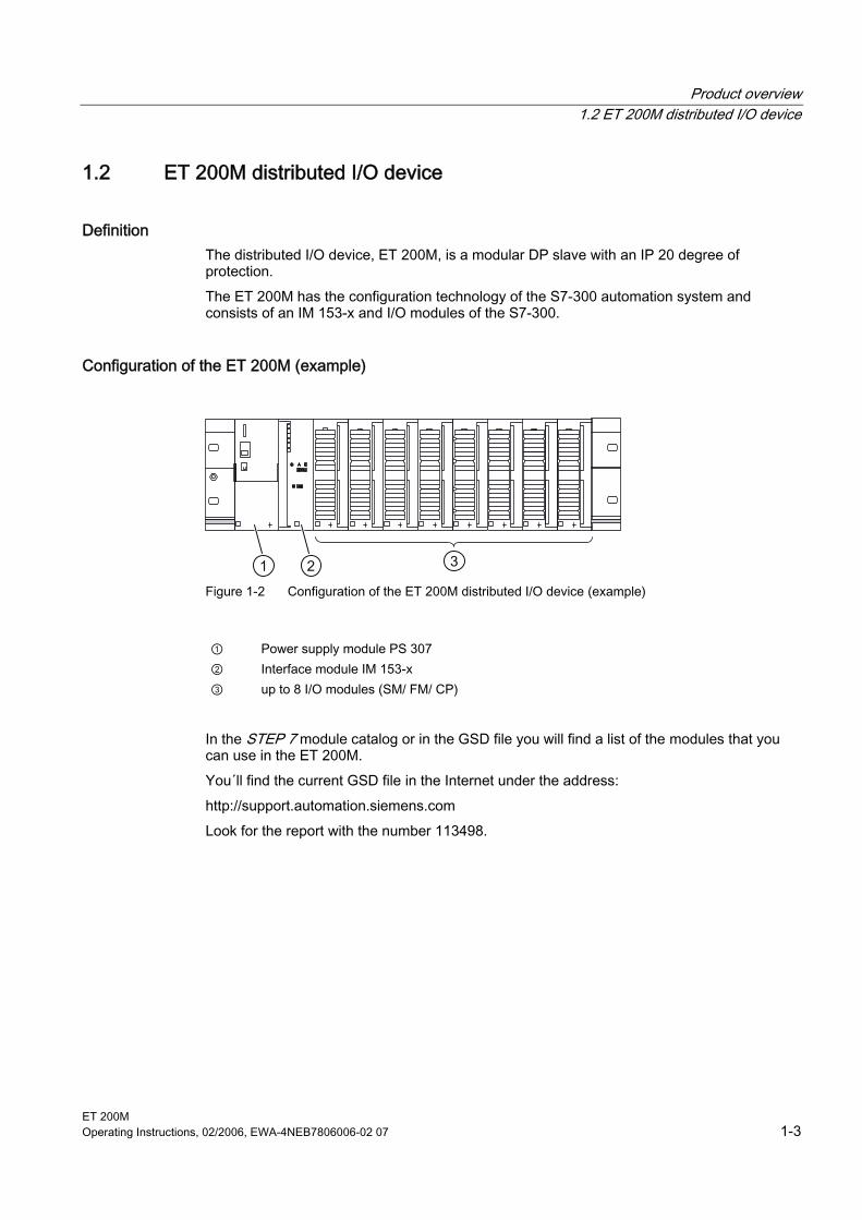
Definition The distributed I/O device, ET 200M, is a modular DP slave with an IP 20 degree of protection. The ET 200M has the configuration technology of the S7-300 automation system and consists of an IM 153-x and I/O modules of the S7-300.
Configuration of the ET 200M (example)
1 2 3 Figure 1-2 Configuration of the ET 200M distributed I/O device (example)
① Power supply module PS 307 ② Interface module IM 153-x ③ up to 8 I/O modules (SM/ FM/ CP)
In the STEP 7 module catalog or in the GSD file you will find a list of the modules that you can use in the ET 200M. You´ll find the current GSD file in the Internet under the address: http://support.automation.siemens.com Look for the report with the number 113498.
Product overview 1.2 ET 200M distributed I/O device
ET 200M 1-4 Operating Instructions, 02/2006, EWA-4NEB7806006-02 07
"SIMATIC S7-DP-Slave" The ET 200M distributed I/O system is a constituent part of the SIMATIC S7 automation system. I.e., STEP 7 provides support when configuring, assigning parameters to and programming the ET 200M in the DP master system as well as for the commissioning and diagnostics. Special services and functions of the IM 153-2 (e.g. configurable FM) can be used to their full extent only in the SIMATIC S7/ PCS 7. If you use the ET 200M on a DP standard master (e.g. S5-95U), the configuration tool will also provide support with the GSD file, but, for example, you must pay attention to the technical data (project data) of the DP master (possible parameter assignment and diagnostics message frame lengths etc.). The PROFIBUS standard IEC 61784-1:2002 Ed1 CP 3/1 also includes the DPV1-mode. You can use this mode only if you integrated the GSD-file Revision ≥ 3. The GSD-file Revision 2 remains available and hence the compatibility with earlier versions of the IM 153-x is assured.
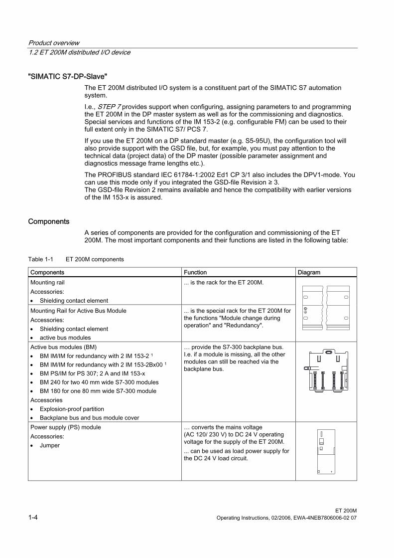
Components A series of components are provided for the configuration and commissioning of the ET 200M. The most important components and their functions are listed in the following table:
Table 1-1 ET 200M components
Components Function Diagram Mounting rail Accessories: • Shielding contact element
... is the rack for the ET 200M.
Mounting Rail for Active Bus Module Accessories: • Shielding contact element • active bus modules
... is the special rack for the ET 200M for the functions "Module change during operation" and "Redundancy".
Active bus modules (BM) • BM IM/IM for redundancy with 2 IM 153-2 1 • BM IM/IM for redundancy with 2 IM 153-2Bx00 1 • BM PS/IM for PS 307; 2 A and IM 153-x • BM 240 for two 40 mm wide S7-300 modules • BM 180 for one 80 mm wide S7-300 module Accessories • Explosion-proof partition • Backplane bus and bus module cover
… provide the S7-300 backplane bus. I.e. if a module is missing, all the other modules can still be reached via the backplane bus.
Power supply (PS) module Accessories: • Jumper
… converts the mains voltage (AC 120/ 230 V) to DC 24 V operating voltage for the supply of the ET 200M. ... can be used as load power supply for the DC 24 V load circuit.
Product overview 1.2 ET 200M distributed I/O device
ET 200M Operating Instructions, 02/2006, EWA-4NEB7806006-02 07 1-5
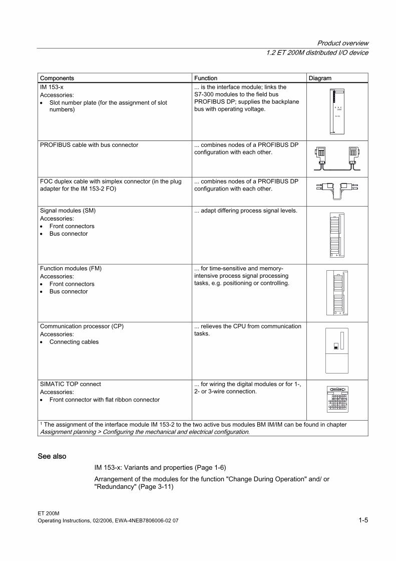
Components Function Diagram IM 153-x Accessories: • Slot number plate (for the assignment of slot
numbers)
... is the interface module; links the S7-300 modules to the field bus PROFIBUS DP; supplies the backplane bus with operating voltage.
PROFIBUS cable with bus connector ... combines nodes of a PROFIBUS DP configuration with each other.
FOC duplex cable with simplex connector (in the plug adapter for the IM 153-2 FO)
... combines nodes of a PROFIBUS DP configuration with each other.
Signal modules (SM) Accessories: • Front connectors • Bus connector
... adapt differing process signal levels.
Function modules (FM) Accessories: • Front connectors • Bus connector
... for time-sensitive and memory-intensive process signal processing tasks, e.g. positioning or controlling.
Communication processor (CP) Accessories: • Connecting cables
... relieves the CPU from communication tasks.
SIMATIC TOP connect Accessories: • Front connector with flat ribbon connector
... for wiring the digital modules or for 1-, 2- or 3-wire connection.
1 The assignment of the interface module IM 153-2 to the two active bus modules BM IM/IM can be found in chapter Assignment planning > Configuring the mechanical and electrical configuration.
See also IM 153-x: Variants and properties (Page 1-6) Arrangement of the modules for the function "Change During Operation" and/ or "Redundancy" (Page 3-11)
Product overview 1.3 IM 153-x: Variants and properties
ET 200M 1-6 Operating Instructions, 02/2006, EWA-4NEB7806006-02 07
1.3 1.3 IM 153-x: Variants and properties
Brief overview of the different IM 153-x The IM 153-x contains interface modules for the signal modules (SM), function modules (FM) and communication processors (CP). You have an RS 485 interface (IM 153-2 alternatively also with FOC interface) and offer a graded functional scope. The respective variants of the interface module IM 153-2 with RS 485 or FOC interface have the same functionalities. From the IM 153-1 and IM 153-2 there is also a variant for use in other operating conditions (outdoors).
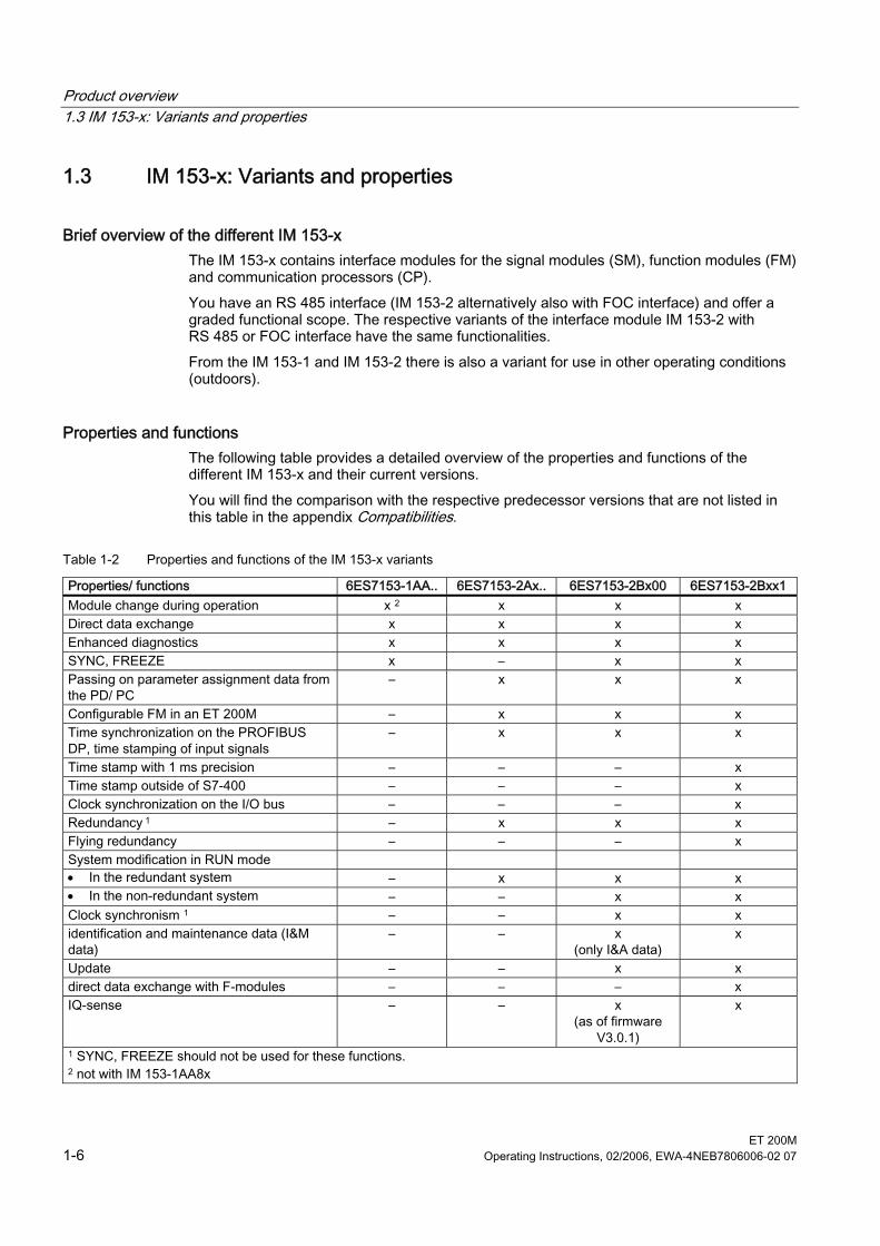
Properties and functions The following table provides a detailed overview of the properties and functions of the different IM 153-x and their current versions. You will find the comparison with the respective predecessor versions that are not listed in this table in the appendix Compatibilities.
Table 1-2 Properties and functions of the IM 153-x variants
Properties/ functions 6ES7153-1AA.. 6ES7153-2Ax.. 6ES7153-2Bx00 6ES7153-2Bxx1 Module change during operation x 2 x x x Direct data exchange x x x x Enhanced diagnostics x x x x SYNC, FREEZE x – x x Passing on parameter assignment data from the PD/ PC
– x x x
Configurable FM in an ET 200M – x x x Time synchronization on the PROFIBUS DP, time stamping of input signals
– x x x
Time stamp with 1 ms precision – – – x Time stamp outside of S7-400 – – – x Clock synchronization on the I/O bus – – – x Redundancy 1 – x x x Flying redundancy – – – x System modification in RUN mode • In the redundant system – x x x • In the non-redundant system – – x x Clock synchronism 1 – – x x identification and maintenance data (I&M data)
– – x (only I&A data)
x
Update – – x x direct data exchange with F-modules – – – x IQ-sense – – x
(as of firmware V3.0.1)
x
1 SYNC, FREEZE should not be used for these functions. 2 not with IM 153-1AA8x
Product overview 1.3 IM 153-x: Variants and properties
ET 200M Operating Instructions, 02/2006, EWA-4NEB7806006-02 07 1-7
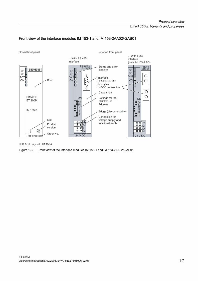
Front view of the interface modules IM 153-1 and IM 153-2AA02/-2AB01
Figure 1-3 Front view of the interface modules IM 153-1 and IM 153-2AA02/-2AB01
Product overview 1.3 IM 153-x: Variants and properties
ET 200M 1-8 Operating Instructions, 02/2006, EWA-4NEB7806006-02 07
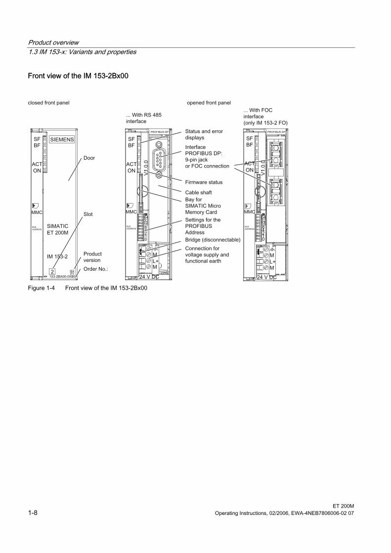
Front view of the IM 153-2Bx00
Figure 1-4 Front view of the IM 153-2Bx00
Product overview 1.3 IM 153-x: Variants and properties
ET 200M Operating Instructions, 02/2006, EWA-4NEB7806006-02 07 1-9
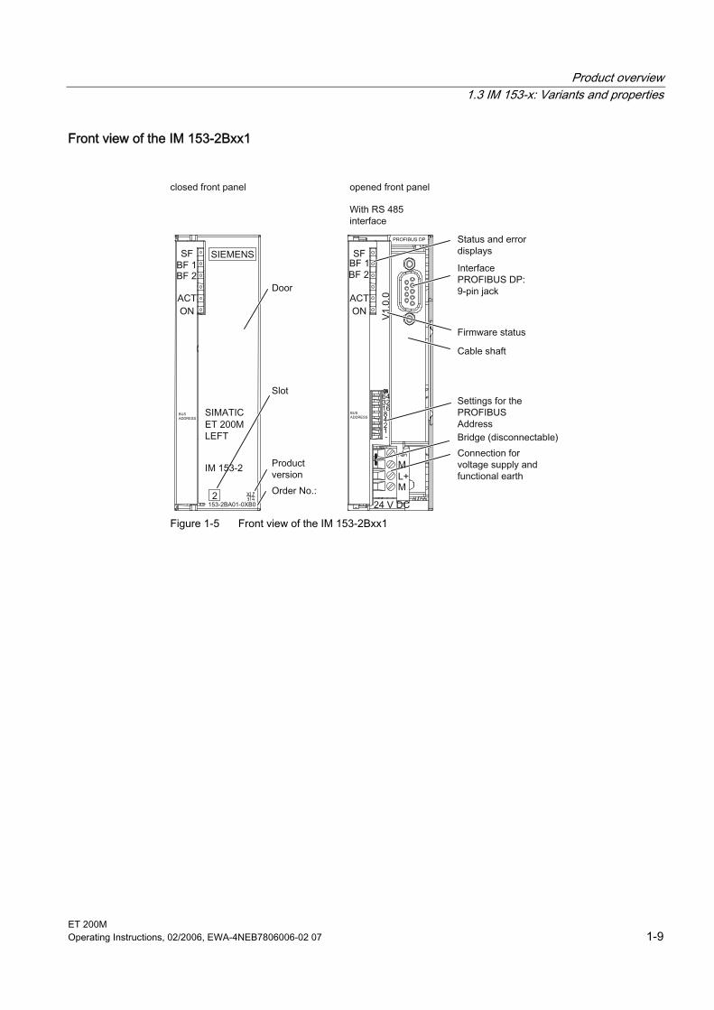
Front view of the IM 153-2Bxx1
Figure 1-5 Front view of the IM 153-2Bxx1

Product overview 1.3 IM 153-x: Variants and properties
ET 200M 1-10 Operating Instructions, 02/2006, EWA-4NEB7806006-02 07
ET 200M Operating Instructions, 02/2006, EWA-4NEB7806006-02 07 2-1
Brief instructions on commissioning 22.1 2.1 Introduction
Introduction The following simple example shows you how to commission the ET 200M step by step. • Installing and wiring the ET 200M • Configuring with STEP 7 • Linking to the User Program • Switching on the ET 200M • Evaluating the diagnostics:
– Encoder supply short circuit after M on the digital input module – Short circuit after L+ on the digital output module
Requirements • You have configured an S7 station, consisting of a power supply module and a DP
master (e.g. CPU 315-2 DP). For this example a CPU 315-2 DP is used as the DP master. You can of course use any other DP master (standard IEC 61784-1:2002 Ed1 CP 3/1).
• The current STEP 7 version is fully installed on your programming device (PD). There may be restrictions if using older versions of STEP 7. You have experience with STEP 7.
• The PD is connected to the DP master.
Brief instructions on commissioning 2.1 Introduction
ET 200M 2-2 Operating Instructions, 02/2006, EWA-4NEB7806006-02 07
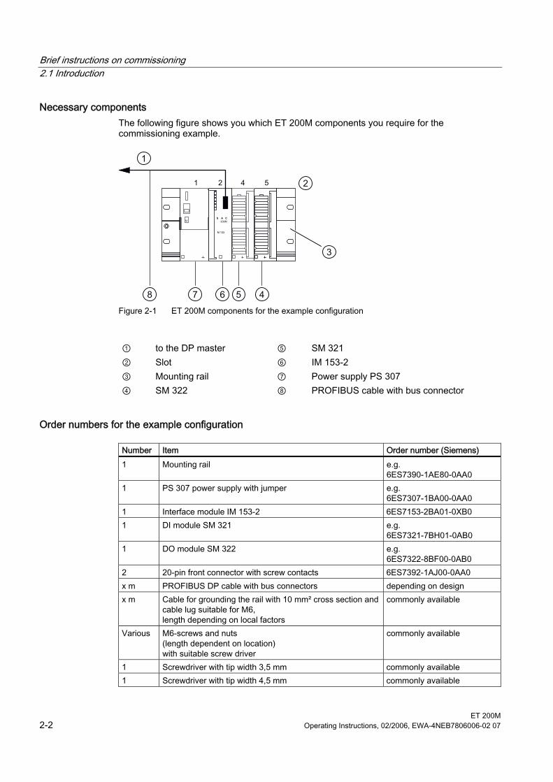
Necessary components The following figure shows you which ET 200M components you require for the commissioning example.
1
2
3
45678 Figure 2-1 ET 200M components for the example configuration
① to the DP master ⑤ SM 321 ② Slot ⑥ IM 153-2 ③ Mounting rail ⑦ Power supply PS 307 ④ SM 322 ⑧ PROFIBUS cable with bus connector
Order numbers for the example configuration
Number Item Order number (Siemens) 1 Mounting rail e.g.
6ES7390-1AE80-0AA0 1 PS 307 power supply with jumper e.g.
6ES7307-1BA00-0AA0 1 Interface module IM 153-2 6ES7153-2BA01-0XB0 1 DI module SM 321 e.g.
6ES7321-7BH01-0AB0 1 DO module SM 322 e.g.
6ES7322-8BF00-0AB0 2 20-pin front connector with screw contacts 6ES7392-1AJ00-0AA0 x m PROFIBUS DP cable with bus connectors depending on design x m Cable for grounding the rail with 10 mm² cross section and
cable lug suitable for M6, length depending on local factors
commonly available
Various M6-screws and nuts (length dependent on location) with suitable screw driver
commonly available
1 Screwdriver with tip width 3,5 mm commonly available 1 Screwdriver with tip width 4,5 mm commonly available
Brief instructions on commissioning 2.2 Mounting the ET 200M
ET 200M Operating Instructions, 02/2006, EWA-4NEB7806006-02 07 2-3
Number Item Order number (Siemens) 1 Side cutters and wire stripping tools commonly available 1 Tool for crimping wire-end ferrules commonly available Approx. 2 m
Stranded wire with 1 mm2 cross section with appropriate wire end ferrules, type A, length 6 mm
commonly available
2 one-pin on button commonly available 1 24 V indicator lamp commonly available
2.2 2.2 Mounting the ET 200M
Procedure 1. Mount the rail on a firm base so that there is at least 40 mm clearance above and below
the rail. 2. Starting from the left side, mount the individual modules on the rail (plug in the bus
connectors (not for PS 307 and the last module) – engage – swing in – screw down). Observe the following sequence: – Power supply PS 307 – Interface module IM 153-2 – DI module SM 321 – DO module SM 322
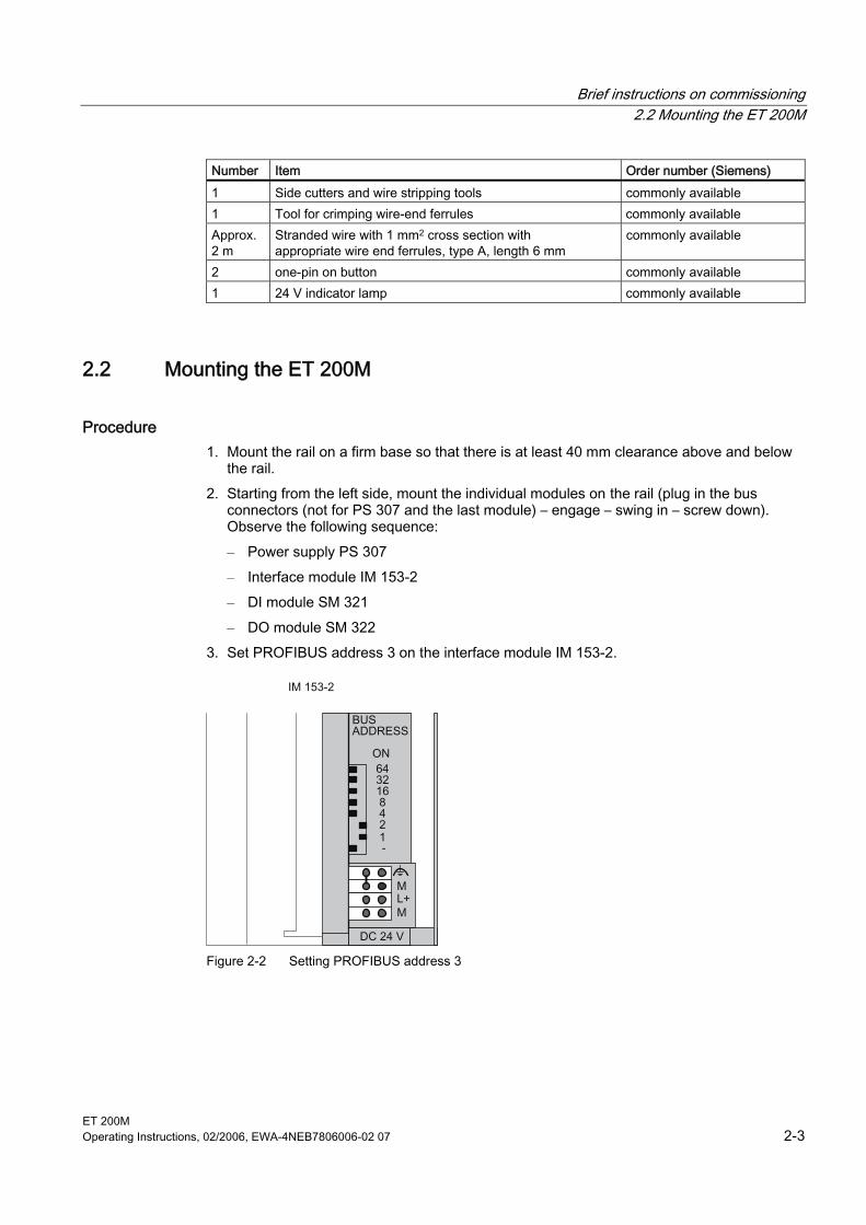
3. Set PROFIBUS address 3 on the interface module IM 153-2.
Figure 2-2 Setting PROFIBUS address 3
Brief instructions on commissioning 2.3 Wiring the ET 200M
ET 200M 2-4 Operating Instructions, 02/2006, EWA-4NEB7806006-02 07
2.3 2.3 Wiring the ET 200M
Mounting rail 1. Connect the rail to the protective conductor. An M6 screw is provided on the rail for this
purpose. Minimum cross-section from the conductor to the protective conductor: 10 mm2
Warning
You could touch live wires if the power supply module PS 307 is switched on or the supply cable of the power supply is connected to the mains supply. Make sure the ET 200M is de-energized before doing any wiring.
Power supply and IM 153-2 1. Open the front doors of the PS and IM. 2. Undo the strain-relief assembly on the PS 307. Strip the power supply cable. 3. If necessary, attach wire end ferrules (in the case of multi-conductor cables). Then
connect to the PS 307 (see the following figure). 4. Screw the strain-relief assembly tight. 5. Insert the jumper in the PS 307 and the IM 153-2 and tighten it (refer to following figure). 6. Check that the switch for selecting the mains voltage is set correctly to your mains
voltage on the PS 307. The power supply module is factory-set to a mains voltage of 230 V AC. You can change the setting in the following way: Remove the protective cover using a screwdriver, set the switch to the available mains voltage and reattach the protective cover.
7. Insert the PROFIBUS DP cable between the DP master (2nd DP interface) and the IM 153-2. The terminating resistors in both connectors must be switched on.
Front Connectors of the DI and DO 1. Open the front doors of the DI and DO. 2. Move the front connector to the wiring position:
To do so, push a front connector into each DI and DO until it engages. The front connector still protrudes from the module in this position. In the wiring position a wired front connector has no contact with the module.
3. Strip 6 mm of insulation off the ends of the wires you want to insert into the front connector and then attach appropriate wire end ferrules to the wire ends.
4. Wire the front connector of the DI in the following way: Terminal 1: L+ of PS; Terminal 20: M of PS; Terminal 3: Button 1; Terminal 4: Button 2; Terminal 10: Free cable ends of button (see the following figure)
Brief instructions on commissioning 2.3 Wiring the ET 200M
ET 200M Operating Instructions, 02/2006, EWA-4NEB7806006-02 07 2-5
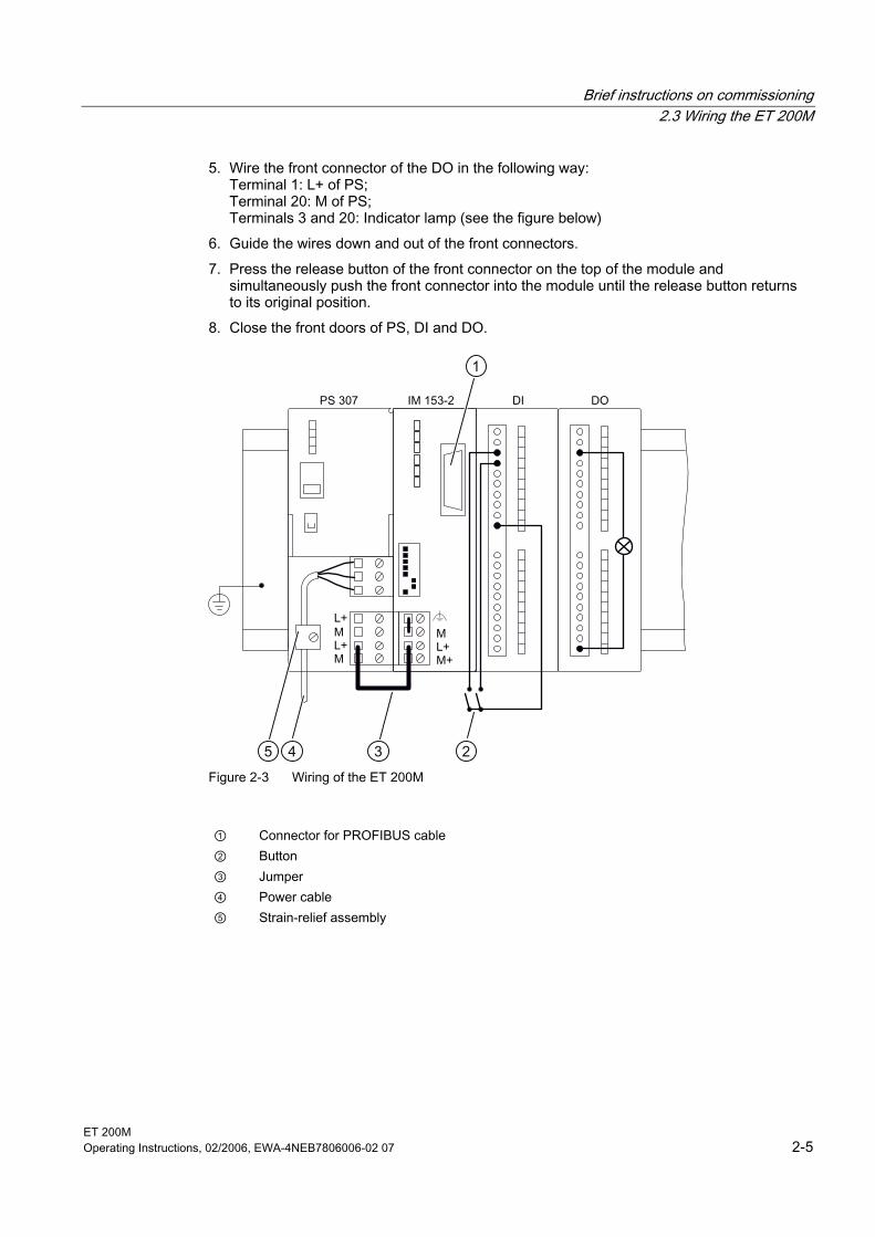
5. Wire the front connector of the DO in the following way: Terminal 1: L+ of PS; Terminal 20: M of PS; Terminals 3 and 20: Indicator lamp (see the figure below)
6. Guide the wires down and out of the front connectors. 7. Press the release button of the front connector on the top of the module and
simultaneously push the front connector into the module until the release button returns to its original position.
8. Close the front doors of PS, DI and DO.
1
2345 Figure 2-3 Wiring of the ET 200M
① Connector for PROFIBUS cable ② Button ③ Jumper ④ Power cable ⑤ Strain-relief assembly
Brief instructions on commissioning 2.4 Putting Hardware into Service
ET 200M 2-6 Operating Instructions, 02/2006, EWA-4NEB7806006-02 07
2.4 2.4 Putting Hardware into Service
Procedure 1. Use the PD cable to connect the PD to the DP master (MPI interface). Make sure that the
terminating resistors in the connectors are switched on. Set the mode switch to STOP. 2. Connect the supply cable to the power supply and then switch on the power supply
module for the DP master. The 24 V DC LED lights up on the PS. With the CPU, all the LEDs light up briefly; the SF LED, the BAT LED and the DC5V LED remain switched on. The STOP LED flashes for 3 seconds and then remains on.
3. Insert the backup battery: – Plug the backup battery connector into the appropriate socket in the battery
compartment of the CPU. The notch on the connector must point to the left. – Insert the backup battery into the battery compartment of the CPU. – Close the front door of the CPU. The BATF-LED goes out and then shortly afterwards the SF LED follows.
4. Boot the programming device. 5. Reset the CPU 315-2 DP:
– Turn the mode switch to MRES. Hold the mode selector at this position until the STOP LED lights up for the second time and then remains lit (approx. 3 seconds)
– You must turn the mode switch back to MRES within 3 s. The STOP LED begins to flash rapidly and the CPU performs a reset. The CPU has completed the memory reset when the STOP LED remains permanently lit again.
Brief instructions on commissioning 2.5 Configuring the ET 200M in the SIMATIC manager
ET 200M Operating Instructions, 02/2006, EWA-4NEB7806006-02 07 2-7
2.5 2.5 Configuring the ET 200M in the SIMATIC manager
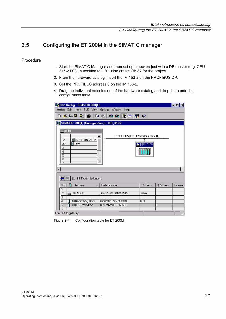
Procedure 1. Start the SIMATIC Manager and then set up a new project with a DP master (e.g. CPU
315-2 DP). In addition to OB 1 also create OB 82 for the project. 2. From the hardware catalog, insert the IM 153-2 on the PROFIBUS DP. 3. Set the PROFIBUS address 3 on the IM 153-2. 4. Drag the individual modules out of the hardware catalog and drop them onto the
configuration table.
Figure 2-4 Configuration table for ET 200M
Brief instructions on commissioning 2.5 Configuring the ET 200M in the SIMATIC manager
ET 200M 2-8 Operating Instructions, 02/2006, EWA-4NEB7806006-02 07
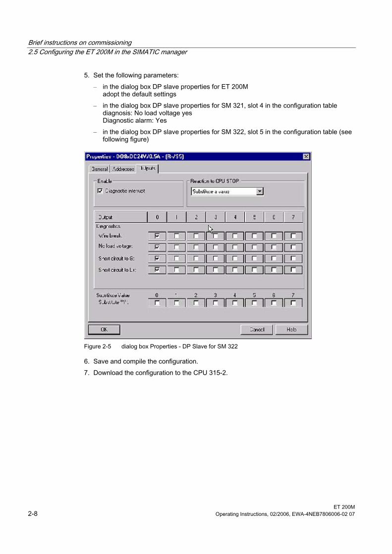
5. Set the following parameters: – in the dialog box DP slave properties for ET 200M
adopt the default settings – in the dialog box DP slave properties for SM 321, slot 4 in the configuration table
diagnosis: No load voltage yes Diagnostic alarm: Yes
– in the dialog box DP slave properties for SM 322, slot 5 in the configuration table (see following figure)
Figure 2-5 dialog box Properties - DP Slave for SM 322
6. Save and compile the configuration. 7. Download the configuration to the CPU 315-2.
Brief instructions on commissioning 2.6 Creating a user program
ET 200M Operating Instructions, 02/2006, EWA-4NEB7806006-02 07 2-9
2.6 2.6 Creating a user program
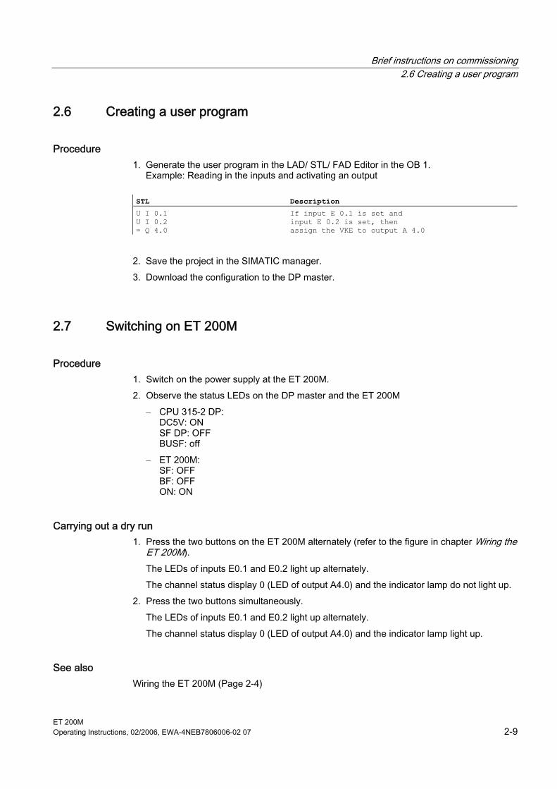
Procedure 1. Generate the user program in the LAD/ STL/ FAD Editor in the OB 1. Example: Reading in the inputs and activating an output
STL Description
U I 0.1 U I 0.2 = Q 4.0
If input E 0.1 is set and input E 0.2 is set, then assign the VKE to output A 4.0
2. Save the project in the SIMATIC manager. 3. Download the configuration to the DP master.
2.7 2.7 Switching on ET 200M
Procedure 1. Switch on the power supply at the ET 200M. 2. Observe the status LEDs on the DP master and the ET 200M
– CPU 315-2 DP: DC5V: ON SF DP: OFF BUSF: off
– ET 200M: SF: OFF BF: OFF ON: ON
Carrying out a dry run 1. Press the two buttons on the ET 200M alternately (refer to the figure in chapter Wiring the
ET 200M). The LEDs of inputs E0.1 and E0.2 light up alternately. The channel status display 0 (LED of output A4.0) and the indicator lamp do not light up.
2. Press the two buttons simultaneously. The LEDs of inputs E0.1 and E0.2 light up alternately. The channel status display 0 (LED of output A4.0) and the indicator lamp light up.
See also Wiring the ET 200M (Page 2-4)
Brief instructions on commissioning 2.8 Evaluating diagnostic messages:
ET 200M 2-10 Operating Instructions, 02/2006, EWA-4NEB7806006-02 07
2.8 2.8 Evaluating diagnostic messages:
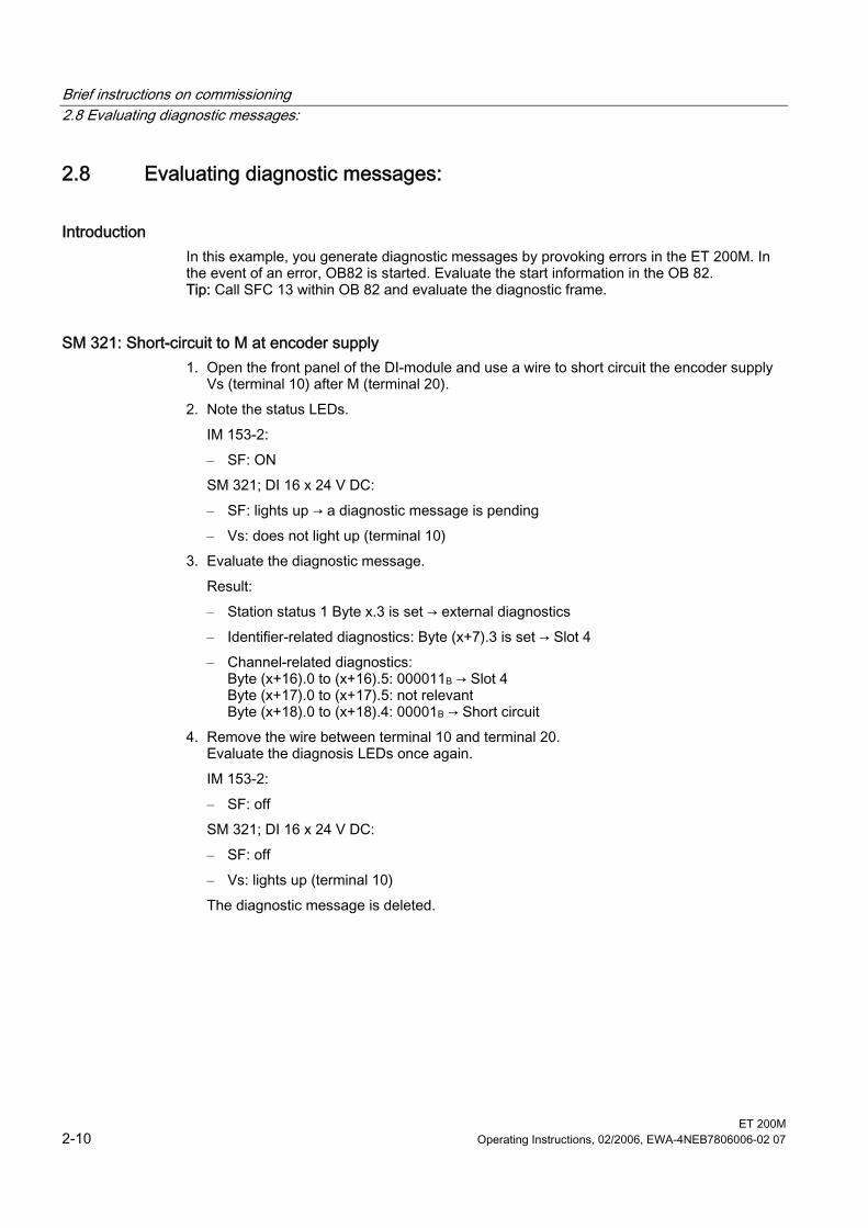
Introduction In this example, you generate diagnostic messages by provoking errors in the ET 200M. In the event of an error, OB82 is started. Evaluate the start information in the OB 82. Tip: Call SFC 13 within OB 82 and evaluate the diagnostic frame.
SM 321: Short-circuit to M at encoder supply 1. Open the front panel of the DI-module and use a wire to short circuit the encoder supply
Vs (terminal 10) after M (terminal 20). 2. Note the status LEDs.
IM 153-2: – SF: ON SM 321; DI 16 x 24 V DC: – SF: lights up → a diagnostic message is pending – Vs: does not light up (terminal 10)
3. Evaluate the diagnostic message. Result: – Station status 1 Byte x.3 is set → external diagnostics – Identifier-related diagnostics: Byte (x+7).3 is set → Slot 4 – Channel-related diagnostics:
Byte (x+16).0 to (x+16).5: 000011B → Slot 4 Byte (x+17).0 to (x+17).5: not relevant Byte (x+18).0 to (x+18).4: 00001B → Short circuit
4. Remove the wire between terminal 10 and terminal 20. Evaluate the diagnosis LEDs once again. IM 153-2: – SF: off SM 321; DI 16 x 24 V DC: – SF: off – Vs: lights up (terminal 10) The diagnostic message is deleted.
Brief instructions on commissioning 2.8 Evaluating diagnostic messages:
ET 200M Operating Instructions, 02/2006, EWA-4NEB7806006-02 07 2-11
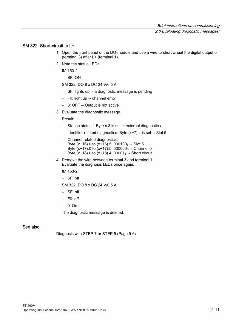
SM 322: Short-circuit to L+ 1. Open the front panel of the DO-module and use a wire to short circuit the digital output 0
(terminal 3) after L+ (terminal 1). 2. Note the status LEDs.
IM 153-2: – SF: ON SM 322; DO 8 x DC 24 V/0,5 A: – SF: lights up → a diagnostic message is pending – F0: light up → channel error – 0: OFF → Output is not active
3. Evaluate the diagnostic message. Result: – Station status 1 Byte x.3 is set → external diagnostics – Identifier-related diagnostics: Byte (x+7).4 is set → Slot 5 – Channel-related diagnostics:
Byte (x+16).0 to (x+16).5: 000100B → Slot 5 Byte (x+17).0 to (x+17).5: 000000B → Channel 0 Byte (x+18).0 to (x+18).4: 00001B → Short circuit
4. Remove the wire between terminal 3 and terminal 1. Evaluate the diagnosis LEDs once again. IM 153-2: – SF: off SM 322; DO 8 x DC 24 V/0,5 A: – SF: off – F0: off – 0: On The diagnostic message is deleted.
See also Diagnosis with STEP 7 or STEP 5 (Page 9-6)

Brief instructions on commissioning 2.8 Evaluating diagnostic messages:
ET 200M 2-12 Operating Instructions, 02/2006, EWA-4NEB7806006-02 07
ET 200M Operating Instructions, 02/2006, EWA-4NEB7806006-02 07 3-1
Assignment planning 33.1 3.1 Configuration variants
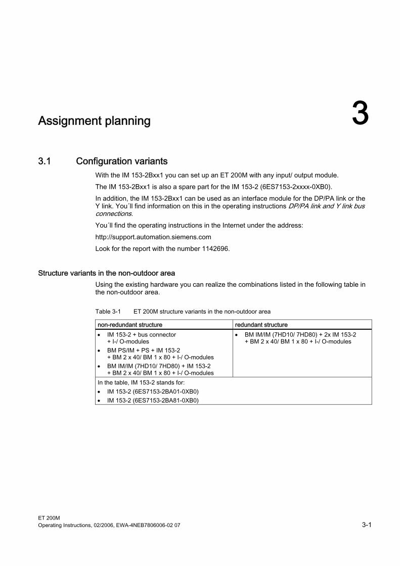
With the IM 153-2Bxx1 you can set up an ET 200M with any input/ output module. The IM 153-2Bxx1 is also a spare part for the IM 153-2 (6ES7153-2xxxx-0XB0). In addition, the IM 153-2Bxx1 can be used as an interface module for the DP/PA link or the Y link. You´ll find information on this in the operating instructions DP/PA link and Y link bus connections. You´ll find the operating instructions in the Internet under the address: http://support.automation.siemens.com Look for the report with the number 1142696.
Structure variants in the non-outdoor area Using the existing hardware you can realize the combinations listed in the following table in the non-outdoor area.
Table 3-1 ET 200M structure variants in the non-outdoor area
non-redundant structure redundant structure • IM 153-2 + bus connector
+ I-/ O-modules • BM PS/IM + PS + IM 153-2
+ BM 2 x 40/ BM 1 x 80 + I-/ O-modules • BM IM/IM (7HD10/ 7HD80) + IM 153-2
+ BM 2 x 40/ BM 1 x 80 + I-/ O-modules
• BM IM/IM (7HD10/ 7HD80) + 2x IM 153-2 + BM 2 x 40/ BM 1 x 80 + I-/ O-modules
In the table, IM 153-2 stands for: • IM 153-2 (6ES7153-2BA01-0XB0) • IM 153-2 (6ES7153-2BA81-0XB0)
Assignment planning 3.1 Configuration variants
ET 200M 3-2 Operating Instructions, 02/2006, EWA-4NEB7806006-02 07
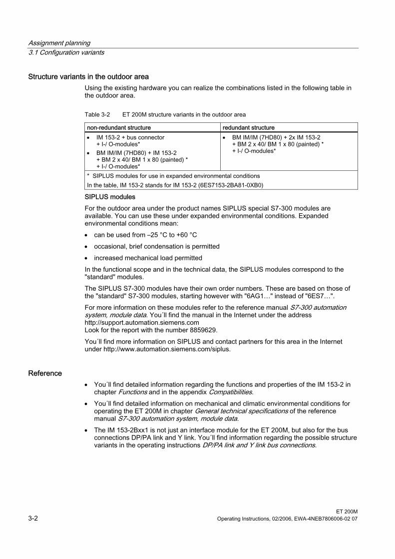
Structure variants in the outdoor area Using the existing hardware you can realize the combinations listed in the following table in the outdoor area.
Table 3-2 ET 200M structure variants in the outdoor area
non-redundant structure redundant structure • IM 153-2 + bus connector
+ I-/ O-modules* • BM IM/IM (7HD80) + IM 153-2
+ BM 2 x 40/ BM 1 x 80 (painted) * + I-/ O-modules*
• BM IM/IM (7HD80) + 2x IM 153-2 + BM 2 x 40/ BM 1 x 80 (painted) * + I-/ O-modules*
* SIPLUS modules for use in expanded environmental conditions In the table, IM 153-2 stands for IM 153-2 (6ES7153-2BA81-0XB0)
SIPLUS modules For the outdoor area under the product names SIPLUS special S7-300 modules are available. You can use these under expanded environmental conditions. Expanded environmental conditions mean: • can be used from –25 °C to +60 °C • occasional, brief condensation is permitted • increased mechanical load permitted In the functional scope and in the technical data, the SIPLUS modules correspond to the "standard" modules. The SIPLUS S7-300 modules have their own order numbers. These are based on those of the "standard" S7-300 modules, starting however with "6AG1…" instead of "6ES7…". For more information on these modules refer to the reference manual S7-300 automation system, module data. You´ll find the manual in the Internet under the address http://support.automation.siemens.com Look for the report with the number 8859629. You´ll find more information on SIPLUS and contact partners for this area in the Internet under http://www.automation.siemens.com/siplus.
Reference • You´ll find detailed information regarding the functions and properties of the IM 153-2 in
chapter Functions and in the appendix Compatibilities. • You´ll find detailed information on mechanical and climatic environmental conditions for
operating the ET 200M in chapter General technical specifications of the reference manual S7-300 automation system, module data.
• The IM 153-2Bxx1 is not just an interface module for the ET 200M, but also for the bus connections DP/PA link and Y link. You´ll find information regarding the possible structure variants in the operating instructions DP/PA link and Y link bus connections.
Assignment planning 3.2 Detecting the configuration variant by means of the IM 153-2
ET 200M Operating Instructions, 02/2006, EWA-4NEB7806006-02 07 3-3
3.2 3.2 Detecting the configuration variant by means of the IM 153-2 During start-up, the IM 153-2 automatically detects which structure variant (ET 200M or DP/PA link or Y link) it is being used in. The IM 153 2 determines its functionality in accordance with this.
Notice The following structure variants ("mixed structures") are not permissible: • Input/ output modules and coupler modules in one structure • Bus modules BM 2 x 40/ BM 1 x 80 and BM DP/PA/ BM Y coupler in one structure
3.3 3.3 Configuration options
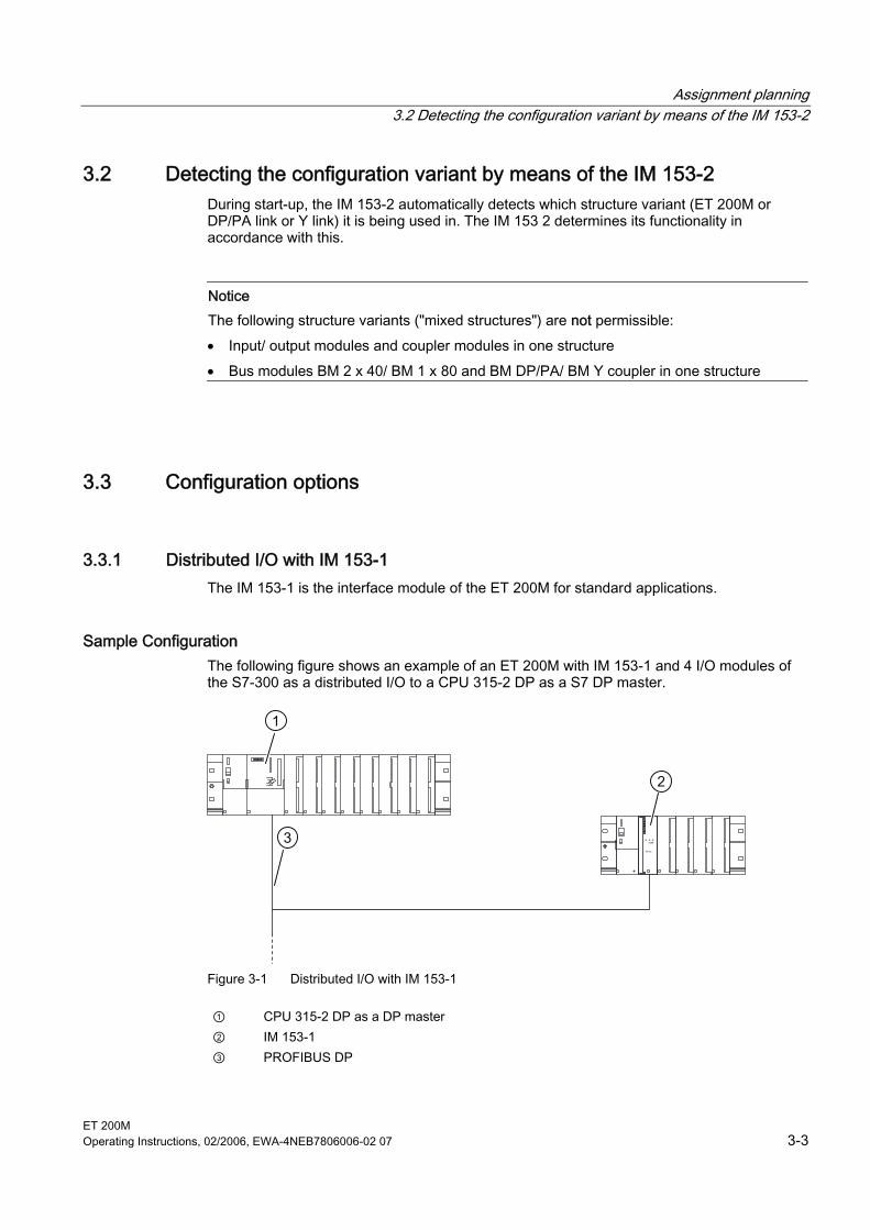
3.3.1 Distributed I/O with IM 153-1 The IM 153-1 is the interface module of the ET 200M for standard applications.
Sample Configuration The following figure shows an example of an ET 200M with IM 153-1 and 4 I/O modules of the S7-300 as a distributed I/O to a CPU 315-2 DP as a S7 DP master.
1
2
3
Figure 3-1 Distributed I/O with IM 153-1
① CPU 315-2 DP as a DP master ② IM 153-1 ③ PROFIBUS DP
Assignment planning 3.3 Configuration options
ET 200M 3-4 Operating Instructions, 02/2006, EWA-4NEB7806006-02 07
3.3.2 Passing on parameter assignment data from the PD/ PC with IM 153-2
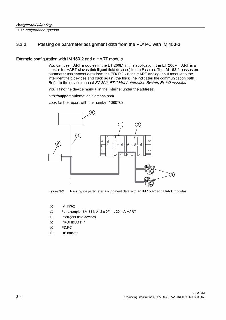
Example configuration with IM 153-2 and a HART module You can use HART modules in the ET 200M In this application, the ET 200M HART is a master for HART slaves (intelligent field devices) in the Ex area. The IM 153-2 passes on parameter assignment data from the PD/ PC via the HART analog input module to the intelligent field devices and back again (the thick line indicates the communication path). Refer to the device manual S7-300, ET 200M Automation System Ex I/O modules. You´ll find the device manual in the Internet under the address: http://support.automation.siemens.com Look for the report with the number 1096709.
1 2
3
6
5
4
Figure 3-2 Passing on parameter assignment data with an IM 153-2 and HART modules
① IM 153-2 ② For example: SM 331; AI 2 x 0/4 … 20 mA HART ③ Intelligent field devices ④ PROFIBUS DP ⑤ PD/PC ⑥ DP master
Assignment planning 3.3 Configuration options
ET 200M Operating Instructions, 02/2006, EWA-4NEB7806006-02 07 3-5
3.3.3 Configurable FM in a configuration with IM 153-2
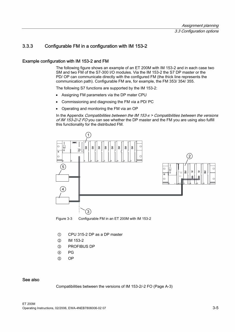
Example configuration with IM 153-2 and FM The following figure shows an example of an ET 200M with IM 153-2 and in each case two SM and two FM of the S7-300 I/O modules. Via the IM 153-2 the S7 DP master or the PD/ OP can communicate directly with the configured FM (the thick line represents the communication path). Configurable FM are, for example, the FM 353/ 354/ 355. The following S7 functions are supported by the IM 153-2: • Assigning FM parameters via the DP mater CPU • Commissioning and diagnosing the FM via a PD/ PC • Operating and monitoring the FM via an OP In the Appendix Compatibilities between the IM 153-x > Compatibilities between the versions of IM 153-2/-2 FO you can see whether the DP master and the FM you are using also fulfill this functionality for the distributed FM.
1
2
3
4
5
Figure 3-3 Configurable FM in an ET 200M with IM 153-2
① CPU 315-2 DP as a DP master ② IM 153-2 ③ PROFIBUS DP ④ PG ⑤ OP
See also Compatibilities between the versions of IM 153-2/-2 FO (Page A-3)
Assignment planning 3.3 Configuration options
ET 200M 3-6 Operating Instructions, 02/2006, EWA-4NEB7806006-02 07
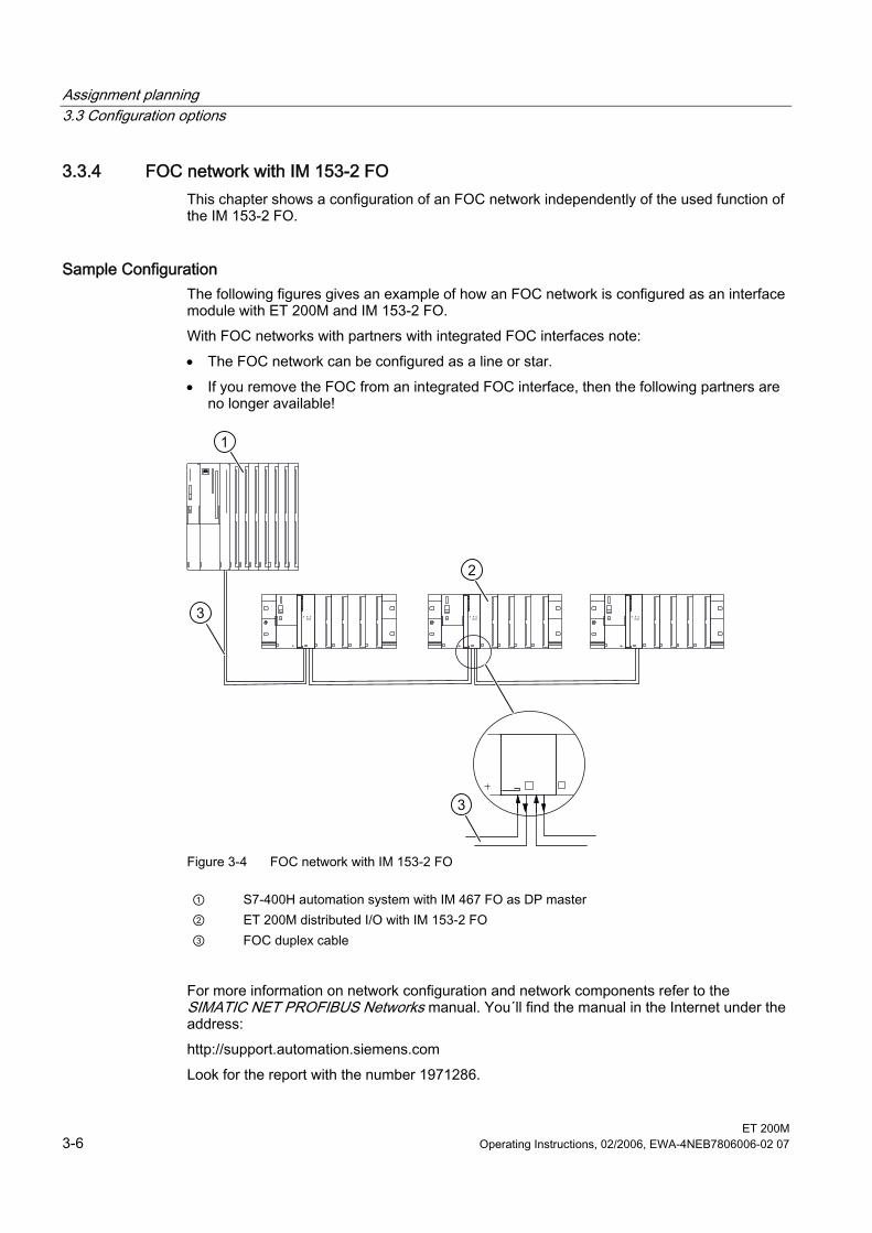
3.3.4 FOC network with IM 153-2 FO This chapter shows a configuration of an FOC network independently of the used function of the IM 153-2 FO.
Sample Configuration The following figures gives an example of how an FOC network is configured as an interface module with ET 200M and IM 153-2 FO. With FOC networks with partners with integrated FOC interfaces note: • The FOC network can be configured as a line or star. • If you remove the FOC from an integrated FOC interface, then the following partners are
no longer available!
1
2
3
Figure 3-4 FOC network with IM 153-2 FO
① S7-400H automation system with IM 467 FO as DP master ② ET 200M distributed I/O with IM 153-2 FO ③ FOC duplex cable
For more information on network configuration and network components refer to the SIMATIC NET PROFIBUS Networks manual. You´ll find the manual in the Internet under the address: http://support.automation.siemens.com Look for the report with the number 1971286.
Assignment planning 3.4 Configuring the mechanical structure
ET 200M Operating Instructions, 02/2006, EWA-4NEB7806006-02 07 3-7
3.4 3.4 Configuring the mechanical structure
3.4.1 Horizontal or vertical configuration
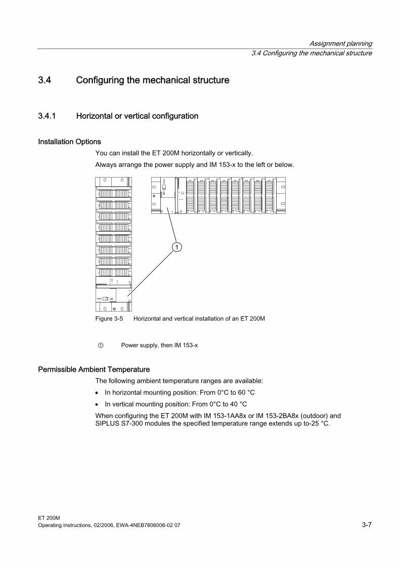
Installation Options You can install the ET 200M horizontally or vertically. Always arrange the power supply and IM 153-x to the left or below.
Figure 3-5 Horizontal and vertical installation of an ET 200M
① Power supply, then IM 153-x
Permissible Ambient Temperature The following ambient temperature ranges are available: • In horizontal mounting position: From 0°C to 60 °C • In vertical mounting position: From 0°C to 40 °C When configuring the ET 200M with IM 153-1AA8x or IM 153-2BA8x (outdoor) and SIPLUS S7-300 modules the specified temperature range extends up to-25 °C.
Assignment planning 3.4 Configuring the mechanical structure
ET 200M 3-8 Operating Instructions, 02/2006, EWA-4NEB7806006-02 07
3.4.2 Clearance Measurements
Controlling If you adhere to the minimum clearance measurements: • you will guarantee heat dissipation of the S7-300 modules. • you will have sufficient space to insert and remove the S7-300 modules. • You have sufficient space for running cables. Using a shielding contact element you can connect shielded lines directly with the rail. This increases the S7-300 rack´s installation height to 185 mm! You must nevertheless adhere to the distance of 40 mm.
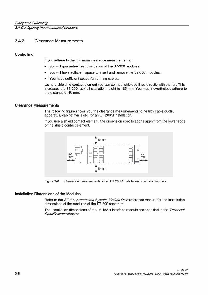
Clearance Measurements The following figure shows you the clearance measurements to nearby cable ducts, apparatus, cabinet walls etc. for an ET 200M installation. If you use a shield contact element, the dimension specifications apply from the lower edge of the shield contact element.
Figure 3-6 Clearance measurements for an ET 200M installation on a mounting rack
Installation Dimensions of the Modules Refer to the S7-300 Automation System, Module Data reference manual for the installation dimensions of the modules of the S7-300 spectrum. The installation dimensions of the IM 153-x interface module are specified in the Technical Specifications chapter.
Assignment planning 3.4 Configuring the mechanical structure
ET 200M Operating Instructions, 02/2006, EWA-4NEB7806006-02 07 3-9
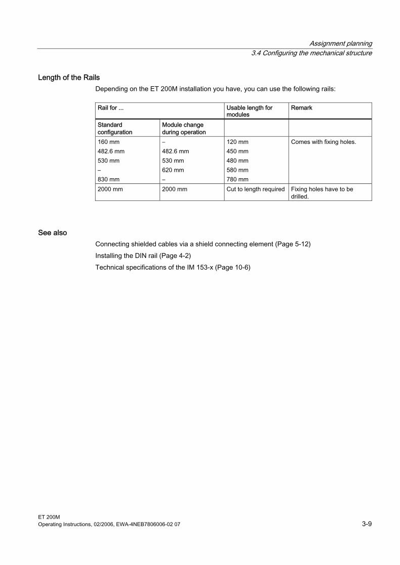
Length of the Rails Depending on the ET 200M installation you have, you can use the following rails:
Rail for ... Usable length for
modules Remark
Standard configuration
Module change during operation
160 mm 482.6 mm 530 mm – 830 mm
– 482.6 mm 530 mm 620 mm –
120 mm 450 mm 480 mm 580 mm 780 mm
Comes with fixing holes.
2000 mm 2000 mm Cut to length required Fixing holes have to be drilled.
See also Connecting shielded cables via a shield connecting element (Page 5-12) Installing the DIN rail (Page 4-2) Technical specifications of the IM 153-x (Page 10-6)
Assignment planning 3.4 Configuring the mechanical structure
ET 200M 3-10 Operating Instructions, 02/2006, EWA-4NEB7806006-02 07
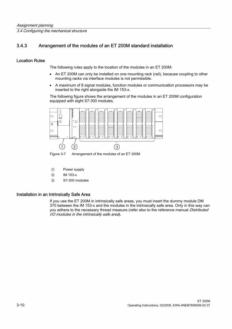
3.4.3 Arrangement of the modules of an ET 200M standard installation
Location Rules The following rules apply to the location of the modules in an ET 200M: • An ET 200M can only be installed on one mounting rack (rail), because coupling to other
mounting racks via interface modules is not permissible. • A maximum of 8 signal modules, function modules or communication processors may be
inserted to the right alongside the IM 153-x. The following figure shows the arrangement of the modules in an ET 200M configuration equipped with eight S7-300 modules.
321 Figure 3-7 Arrangement of the modules of an ET 200M
① Power supply ② IM 153-x ③ S7-300 modules
Installation in an Intrinsically Safe Area If you use the ET 200M in intrinsically safe areas, you must insert the dummy module DM 370 between the IM 153-x and the modules in the intrinsically safe area. Only in this way can you adhere to the necessary thread measure (refer also to the reference manual Distributed I/O modules in the intrinsically safe area).
Assignment planning 3.4 Configuring the mechanical structure
ET 200M Operating Instructions, 02/2006, EWA-4NEB7806006-02 07 3-11
3.4.4 Arrangement of the modules for the function "Change During Operation" and/ or "Redundancy"
Location Rules The following rules apply to the location of the modules in an ET 200M: • An ET 200M can only be installed on one mounting rack (rail), because coupling to other
mounting racks via interface modules is not permissible. • A maximum of 8 signal modules, function modules or communication processors may be
inserted to the right alongside the IM 153-x. • The IM 153-x and all the SM/ FM/ CP must be connected to active bus modules. With the respective configuration, you can compatibly operate the combinations of interface modules IM 153-2 specified in the following table on active bus modules BM IM/IM.
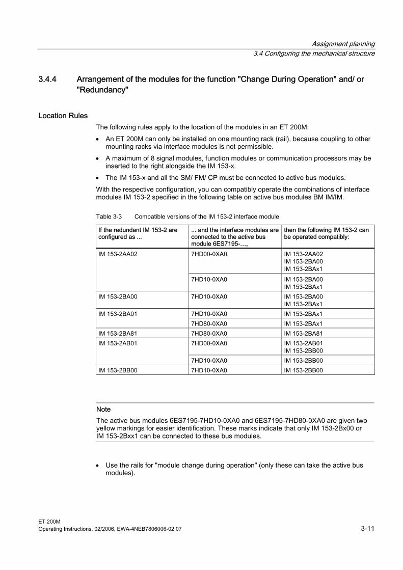
Table 3-3 Compatible versions of the IM 153-2 interface module
If the redundant IM 153-2 are configured as ...
... and the interface modules are connected to the active bus module 6ES7195-…,
then the following IM 153-2 can be operated compatibly:
7HD00-0XA0 IM 153-2AA02 IM 153-2BA00 IM 153-2BAx1
IM 153-2AA02
7HD10-0XA0 IM 153-2BA00 IM 153-2BAx1
IM 153-2BA00 7HD10-0XA0 IM 153-2BA00 IM 153-2BAx1
7HD10-0XA0 IM 153-2BAx1 IM 153-2BA01 7HD80-0XA0 IM 153-2BAx1
IM 153-2BA81 7HD80-0XA0 IM 153-2BA81 7HD00-0XA0 IM 153-2AB01
IM 153-2BB00 IM 153-2AB01
7HD10-0XA0 IM 153-2BB00 IM 153-2BB00 7HD10-0XA0 IM 153-2BB00
Note The active bus modules 6ES7195-7HD10-0XA0 and 6ES7195-7HD80-0XA0 are given two yellow markings for easier identification. These marks indicate that only IM 153-2Bx00 or IM 153-2Bxx1 can be connected to these bus modules.
• Use the rails for "module change during operation" (only these can take the active bus modules).
Assignment planning 3.4 Configuring the mechanical structure
ET 200M 3-12 Operating Instructions, 02/2006, EWA-4NEB7806006-02 07
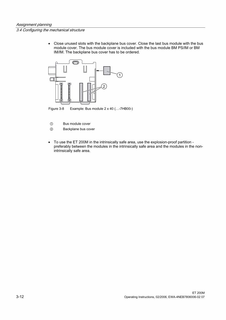
• Close unused slots with the backplane bus cover. Close the last bus module with the bus module cover. The bus module cover is included with the bus module BM PS/IM or BM IM/IM. The backplane bus cover has to be ordered.
2
1
Figure 3-8 Example: Bus module 2 x 40 (…-7HB00-)
① Bus module cover ② Backplane bus cover
• To use the ET 200M in the intrinsically safe area, use the explosion-proof partition -
preferably between the modules in the intrinsically safe area and the modules in the non-intrinsically safe area.
Assignment planning 3.4 Configuring the mechanical structure
ET 200M Operating Instructions, 02/2006, EWA-4NEB7806006-02 07 3-13
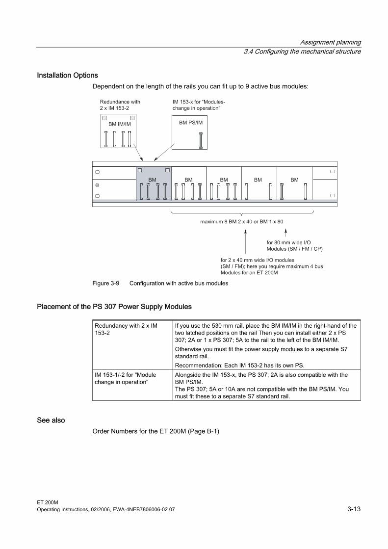
Installation Options Dependent on the length of the rails you can fit up to 9 active bus modules:
Figure 3-9 Configuration with active bus modules
Placement of the PS 307 Power Supply Modules
Redundancy with 2 x IM 153-2
If you use the 530 mm rail, place the BM IM/IM in the right-hand of the two latched positions on the rail Then you can install either 2 x PS 307; 2A or 1 x PS 307; 5A to the rail to the left of the BM IM/IM. Otherwise you must fit the power supply modules to a separate S7 standard rail. Recommendation: Each IM 153-2 has its own PS.
IM 153-1/-2 for "Module change in operation"
Alongside the IM 153-x, the PS 307; 2A is also compatible with the BM PS/IM. The PS 307; 5A or 10A are not compatible with the BM PS/IM. You must fit these to a separate S7 standard rail.
See also Order Numbers for the ET 200M (Page B-1)
Assignment planning 3.5 Configuring the electrical structure
ET 200M 3-14 Operating Instructions, 02/2006, EWA-4NEB7806006-02 07
3.5 3.5 Configuring the electrical structure
3.5.1 General rules and regulations for operating the ET 200M
Introduction Depending on the particular area of application, the ET 200M programmable controller, as part of a plant or system, requires that you observe a number of specific rules and guidelines. Note the safety and accident prevention directives applicable to specific application cases, e.g. the machine guidelines. This section outlines the most important rules you must observe to integrate your ET 200M safely into an existing plant or system.
EMERGENCY-OFF devices Emergency stop devices in accordance with IEC 60204 Safety of machines - Electrical equipment of machines must remain effective in all operating modes of the unit or the system.
Startup of the system after certain events The following table identifies situations you must pay attention to when the system starts up after the occurrence of certain events.
If there is ... then ... • Start-up after voltage drop or failure • Startup of the ET 200M after an
interruption of bus communication
should not cause any dangerous operating states. If necessary, the emergency stop must be forced!
• Start-up after releasing the emergency stop device
• ET 200M start-up without the DP master triggering the ET 200M
There must not be an uncontrolled or undefined startup.
Note on Radio Interference When several electronic components are used within a switch cabinet, the radio interference can overlap. As a result, the permissible level of radio interference intensity in the overall configuration may be exceeded. Tip: Keep such modules as far away from each other as possible, if necessary use shielded cables or filters in the supply lines or HFswitching cabinets.
Assignment planning 3.5 Configuring the electrical structure
ET 200M Operating Instructions, 02/2006, EWA-4NEB7806006-02 07 3-15
Line voltage The following table identifies requirements to be observed for the line voltage.
With ... the ... Stationary plants or systems without all-pole line voltage disconnect switch
There must be a supply isolating switch or a fuse in the building installation system
Load power supplies, power supply modules
The system voltage range set must correspond to the local system voltage
All ET 200M circuits fluctuation/ deviation of the input/ load voltage from the rated value must lie within the permissible tolerances (refer to Technical Specifications of the S7-300 modules)
24 V DC supply The following table identifies requirements to be observed for the 24 V supply.
With ... you must ensure ... Buildings Outdoor lightning protection 24 V DC supply lines, signal lines
Indoor lightning protection to provide lightening protection measures (e.g. lightening protection ductors)
24 V DC supply Safe electrical isolation of safety extra-low voltage
Protection against outside electrical influences The following table identifies requirements you must observe to provide protection against electrical influences or faults.
With ... you must ensure ... All plants or systems in which the ET 200M is integrated
that the unit or the system is connected to the grounding wire in order to discharge electromagnetic interference.
Connection, signal and bus lines The wiring routing and installation are correct. Signal and bus lines Any break of a line or conductor does not result in undefined
states of the plant or system.

Assignment planning 3.5 Configuring the electrical structure
ET 200M 3-16 Operating Instructions, 02/2006, EWA-4NEB7806006-02 07
Rules on the Power Consumption and Power Loss of an ET 200M For their operation, the S7-300 modules use the necessary power from the backplane bus as well as, if necessary, from an external load power supply. • The current consumption of all signal modules from the backplane bus must not exceed
the electrical output that the IM 153-x can supply to the backplane bus. • The PS 307 power supply is dependent on the current consumption from the 24 V load
power supply; this is the result of the total of the current consumption of the signal modules and all other connected loads.
• The power loss of all the components in a cabinet must not exceed the maximum thermal rating of the cabinet. Tip:When establishing the required dimensions of the cabinet, ensure that the temperature inside the cabinet does not exceed the permissible 60°C even where external temperatures are high
You will find the values for the power consumption and power loss of a module under the technical specifications of the relevant modules.
Assignment planning 3.5 Configuring the electrical structure
ET 200M Operating Instructions, 02/2006, EWA-4NEB7806006-02 07 3-17
3.5.2 Operating the ET 200M with process I/O on a grounded supply The following gives information on the overall configuration of an ET 200M to a grounded supply (TN-S-network). The topics covered here are: • Switch-off organs, short-circuit and overload protection in accordance with DIN VDE 0100
and DIN VDE 0113 • Load power supplies and load circuits
Grounded supply With grounded supplies the neutral line of the network is grounded. A simple contact to earth between a live cable and ground or a grounded part of the unit triggers the safety organs.
Components and safety measures Different components and safety measures are prescribed for setting up a complete plant. The nature of the components and the degree of credibility of the safety measures depends on which DIN VDE directive applies to your unit configuration. The following table refers to the two following figures.
Table 3-4 DIN VDE-directives for the configuration of a controller
Comparisons ... Reference to figure
DIN VDE 0100 DIN VDE 0113
Switch-off organ for controllers, signal sensors and final control elements
(1) … part 460: Main switch
… part 1: Separator
Short-circuit and overload protection: in groups for signal sensors and final control elements
(2) … part 725: Single-pole protection of the circuit
… part 1: • with grounded
secondary power circuit: single-pole protection
• otherwise: all-pole protection
Load power supply for AC load circuits with more than five electromagnetic apparatus
(3) metallic isolation with transformers recommended
metallic isolation with transformers required
Assignment planning 3.5 Configuring the electrical structure
ET 200M 3-18 Operating Instructions, 02/2006, EWA-4NEB7806006-02 07
Properties of load power supplies The load power supply supplies input and output circuits (load circuits) as well as sensors and actuators. The following lists the properties of load power supplies that are required in special application cases.
Properties of load power supply required for ... Remarks
Modules that must be supplied with voltages ≤ DC 60 V or ≤ AC 25 V
Safer (electrical) isolation
24 V DC load power supply
The power supplies PS 307 as well as the Siemens load power supplies of the 6EP1 series have this property.
Tolerances of the output voltage:
20.4 V to 28.8 V 24 V DC load power supply 40.8 V to 57.6 V 48 V DC load power supply 51 V to 72 V 60 V DC load power supply
In the case of considerable unevenness of the output voltage, we recommend using a supporting capacitor. Measurement: 200 µF per 1 A load current (with bridge rectification).
Rule: ground the load circuits The load circuits should be grounded. A perfect functioning security is given on account of the mutual reference potential (ground). On the load power supply (terminals L or M) or on the isolation transformer provide a disconnectable connection to the grounding wire (position ④ in the following figure). In the event of faults in the energy distribution, this measure makes it easier for you to localize contacts to earth.
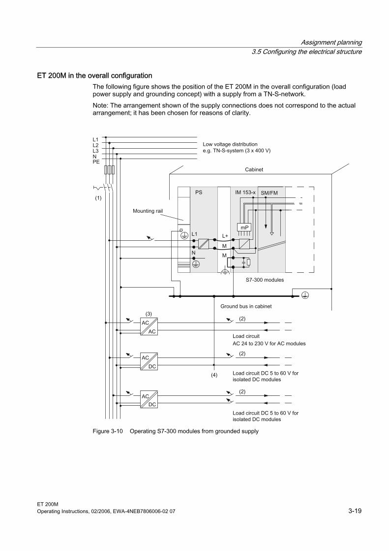
Assignment planning 3.5 Configuring the electrical structure
ET 200M Operating Instructions, 02/2006, EWA-4NEB7806006-02 07 3-19
ET 200M in the overall configuration The following figure shows the position of the ET 200M in the overall configuration (load power supply and grounding concept) with a supply from a TN-S-network. Note: The arrangement shown of the supply connections does not correspond to the actual arrangement; it has been chosen for reasons of clarity.
Figure 3-10 Operating S7-300 modules from grounded supply
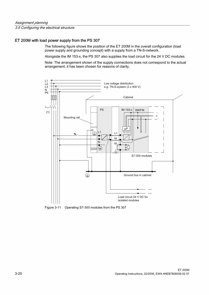
Assignment planning 3.5 Configuring the electrical structure
ET 200M 3-20 Operating Instructions, 02/2006, EWA-4NEB7806006-02 07
ET 200M with load power supply from the PS 307 The following figure shows the position of the ET 200M in the overall configuration (load power supply and grounding concept) with a supply from a TN-S-network. Alongside the IM 153-x, the PS 307 also supplies the load circuit for the 24 V DC modules. Note: The arrangement shown of the supply connections does not correspond to the actual arrangement; it has been chosen for reasons of clarity.
Figure 3-11 Operating S7-300 modules from the PS 307
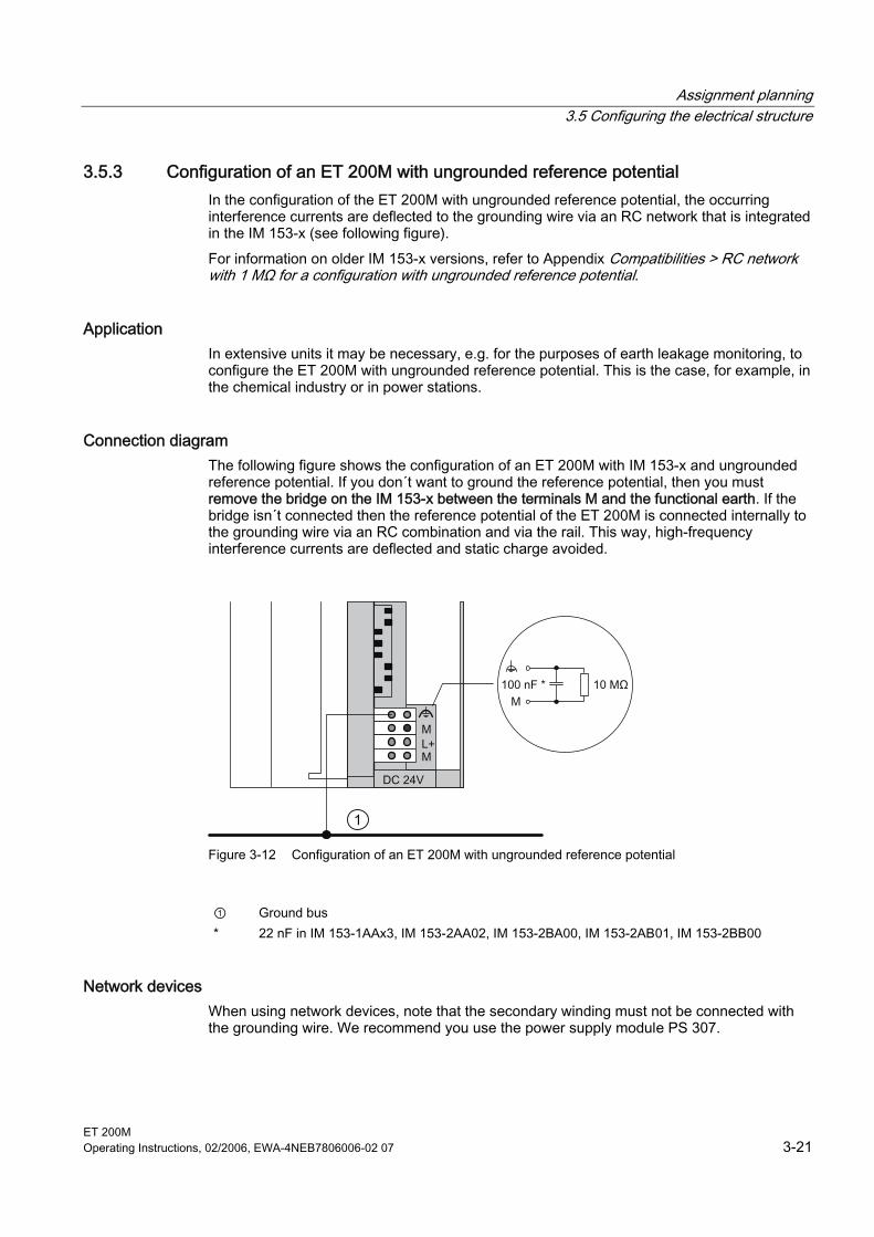
Assignment planning 3.5 Configuring the electrical structure
ET 200M Operating Instructions, 02/2006, EWA-4NEB7806006-02 07 3-21
3.5.3 Configuration of an ET 200M with ungrounded reference potential In the configuration of the ET 200M with ungrounded reference potential, the occurring interference currents are deflected to the grounding wire via an RC network that is integrated in the IM 153-x (see following figure). For information on older IM 153-x versions, refer to Appendix Compatibilities > RC network with 1 MΩ for a configuration with ungrounded reference potential.
Application In extensive units it may be necessary, e.g. for the purposes of earth leakage monitoring, to configure the ET 200M with ungrounded reference potential. This is the case, for example, in the chemical industry or in power stations.
Connection diagram The following figure shows the configuration of an ET 200M with IM 153-x and ungrounded reference potential. If you don´t want to ground the reference potential, then you must remove the bridge on the IM 153-x between the terminals M and the functional earth. If the bridge isn´t connected then the reference potential of the ET 200M is connected internally to the grounding wire via an RC combination and via the rail. This way, high-frequency interference currents are deflected and static charge avoided.
1
Figure 3-12 Configuration of an ET 200M with ungrounded reference potential
① Ground bus * 22 nF in IM 153-1AAx3, IM 153-2AA02, IM 153-2BA00, IM 153-2AB01, IM 153-2BB00
Network devices When using network devices, note that the secondary winding must not be connected with the grounding wire. We recommend you use the power supply module PS 307.
Assignment planning 3.5 Configuring the electrical structure
ET 200M 3-22 Operating Instructions, 02/2006, EWA-4NEB7806006-02 07
Filtering the 24 V DC supply If, with a configuration with ungrounded reference potential, you supply the IM 153-x from a battery, you must suppress the 24 V DC power supply. To do this, use a Siemens mains filter, e.g. B84102-K40.
Insulation monitoring If, on account of double faults, dangerous situations could occur, then you must provide insulation monitoring.
See also RC Network with 1 MΩ for Configuration with ungrounded reference potential (Page A-6)
3.5.4 Configuration of the ET 200M with isolated modules
Definition With a configuration using isolated modules, the reference potentials are electrically isolated from the control circuit (Minternal ) and load circuit (Mexternal) (refer also to the following figure).
Application area You use electrically isolated modules for: • all AC load circuits • DC load circuits with separate reference potential, e.g.
– DC load circuits, the encoders for which have different reference potentials (e.g. if grounded encoders are used far away from the controller and an equipotential bonding isn´t possible)
– DC power circuits, the positive poles (L +) of which are grounded (battery circuit).
Isolated modules and grounding concept You can use isolated modules irrespective of whether the reference potential of the ET 200M is grounded or not.
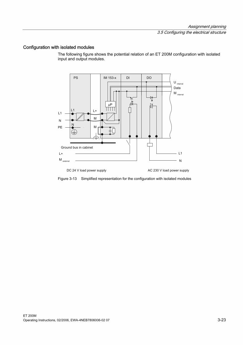
Assignment planning 3.5 Configuring the electrical structure
ET 200M Operating Instructions, 02/2006, EWA-4NEB7806006-02 07 3-23
Configuration with isolated modules The following figure shows the potential relation of an ET 200M configuration with isolated input and output modules.
Figure 3-13 Simplified representation for the configuration with isolated modules
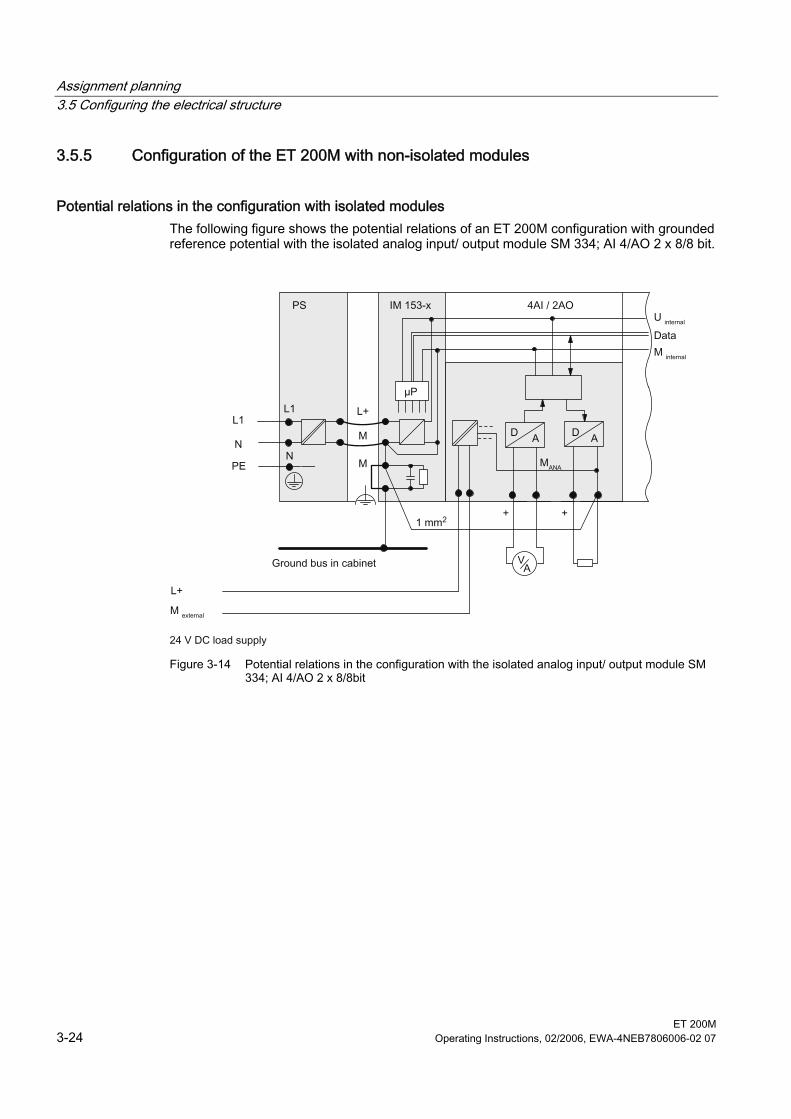
Assignment planning 3.5 Configuring the electrical structure
ET 200M 3-24 Operating Instructions, 02/2006, EWA-4NEB7806006-02 07
3.5.5 Configuration of the ET 200M with non-isolated modules
Potential relations in the configuration with isolated modules The following figure shows the potential relations of an ET 200M configuration with grounded reference potential with the isolated analog input/ output module SM 334; AI 4/AO 2 x 8/8 bit.
Figure 3-14 Potential relations in the configuration with the isolated analog input/ output module SM
334; AI 4/AO 2 x 8/8bit
ET 200M Operating Instructions, 02/2006, EWA-4NEB7806006-02 07 4-1
Installation 44.1 4.1 Overview
Introduction In this chapter we will show you how to prepare and install the ET 200M components. There are two configuration types for the ET 200M: • Standard configuration with rail and bus connectors between the modules • Configuration with active bus modules for the function "Change During Operation" and/ or
"Redundancy" To set up an ET 200M, you must take into account the mechanical and electrical configuration. Information can be found in the Application Planning section.
Open components The modules of an ET 200M are open equipment. That means you can only install the ET 200M in housings, cabinets or electrical operating areas. These housings, cabinets and electrical operating areas should only be accessible by means of a key or a special tool. Only trained or authorized personnel should have access to the housings, cabinets or electrical operating areas.
Installation 4.2 Installation
ET 200M 4-2 Operating Instructions, 02/2006, EWA-4NEB7806006-02 07
4.2 4.2 Installation
4.2.1 Mounting Sequence
Mounting steps Depending on the desired structure you have to carry out the following steps consecutively during mounting: 1. Installing the mounting rail 2. Mounting a Module
– At standard configuration: Mount the modules on the rail – At configuration with active bus modules: Mount the active bus modules and modules
3. Carry out the concluding work: After mounting Detailled information about the individual mounting steps can be found below in the sections of the same name.
4.2.2 Installing the DIN rail
Uniform Installation All the information in this section applies to both the DIN rail and the rail for active bus modules.
Mounting Rail for Active Bus Module To configure an ET 200M with the function "Module change during operation" and/ or "Redundancy" use the associated rails with the order number 6ES7195-1Gxx0-0XA0. Only these rails can take the active bus modules.
Do you want to install a 2-metre rail? If not, you can skip this section and read on from Dimensioned Drawing for Fixing Holes. If you do you need to prepare the 2-metre rail for installation. Proceed as follows: 1. Shorten the 2-metre rail to the required length. 2. Mark out:
– four holes for fixing screws (dimension: refer to the following figure and following table) – One hole to take the fixing screw for the protective conductor.
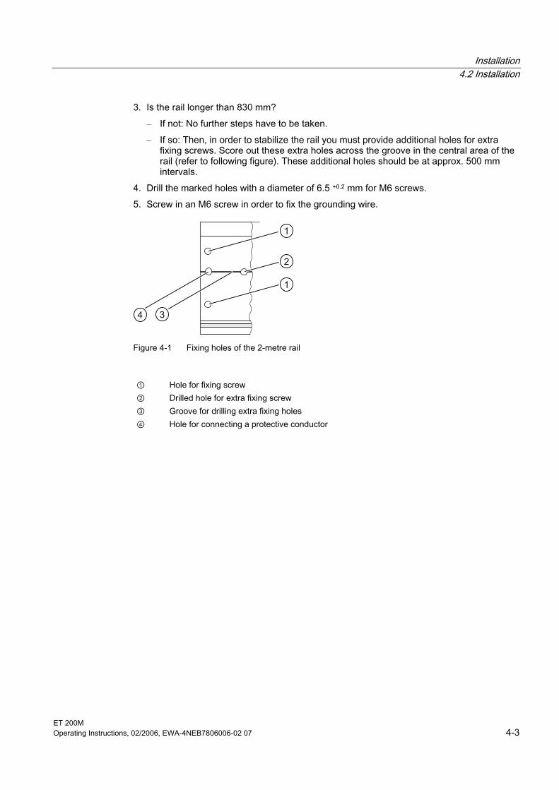
Installation 4.2 Installation
ET 200M Operating Instructions, 02/2006, EWA-4NEB7806006-02 07 4-3
3. Is the rail longer than 830 mm? – If not: No further steps have to be taken. – If so: Then, in order to stabilize the rail you must provide additional holes for extra
fixing screws. Score out these extra holes across the groove in the central area of the rail (refer to following figure). These additional holes should be at approx. 500 mm intervals.
4. Drill the marked holes with a diameter of 6.5 +0.2 mm for M6 screws. 5. Screw in an M6 screw in order to fix the grounding wire.
1
2
Figure 4-1 Fixing holes of the 2-metre rail
① Hole for fixing screw ② Drilled hole for extra fixing screw ③ Groove for drilling extra fixing holes ④ Hole for connecting a protective conductor
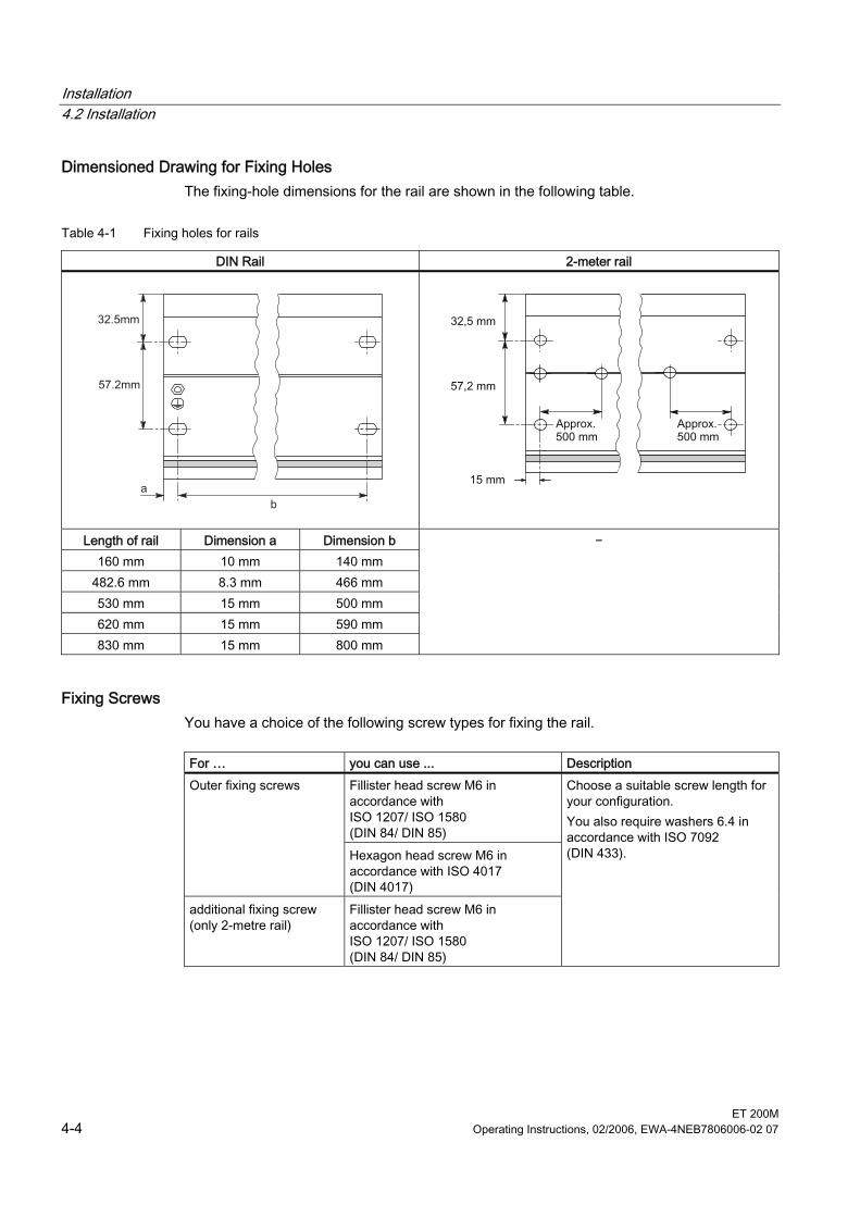
Installation 4.2 Installation
ET 200M 4-4 Operating Instructions, 02/2006, EWA-4NEB7806006-02 07
Dimensioned Drawing for Fixing Holes The fixing-hole dimensions for the rail are shown in the following table.
Table 4-1 Fixing holes for rails
DIN Rail 2-meter rail
Length of rail Dimension a Dimension b 160 mm 10 mm 140 mm
482.6 mm 8.3 mm 466 mm 530 mm 15 mm 500 mm 620 mm 15 mm 590 mm 830 mm 15 mm 800 mm
−
Fixing Screws You have a choice of the following screw types for fixing the rail.
For … you can use ... Description
Fillister head screw M6 in accordance with ISO 1207/ ISO 1580 (DIN 84/ DIN 85)
Outer fixing screws
Hexagon head screw M6 in accordance with ISO 4017 (DIN 4017)
additional fixing screw (only 2-metre rail)
Fillister head screw M6 in accordance with ISO 1207/ ISO 1580 (DIN 84/ DIN 85)
Choose a suitable screw length for your configuration. You also require washers 6.4 in accordance with ISO 7092 (DIN 433).
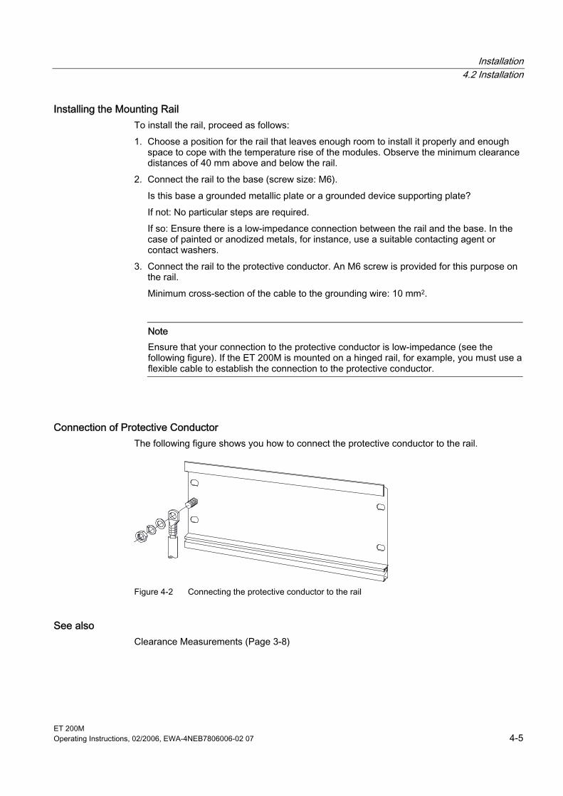
Installation 4.2 Installation
ET 200M Operating Instructions, 02/2006, EWA-4NEB7806006-02 07 4-5
Installing the Mounting Rail To install the rail, proceed as follows: 1. Choose a position for the rail that leaves enough room to install it properly and enough
space to cope with the temperature rise of the modules. Observe the minimum clearance distances of 40 mm above and below the rail.
2. Connect the rail to the base (screw size: M6). Is this base a grounded metallic plate or a grounded device supporting plate? If not: No particular steps are required. If so: Ensure there is a low-impedance connection between the rail and the base. In the case of painted or anodized metals, for instance, use a suitable contacting agent or contact washers.
3. Connect the rail to the protective conductor. An M6 screw is provided for this purpose on the rail. Minimum cross-section of the cable to the grounding wire: 10 mm2.
Note Ensure that your connection to the protective conductor is low-impedance (see the following figure). If the ET 200M is mounted on a hinged rail, for example, you must use a flexible cable to establish the connection to the protective conductor.
Connection of Protective Conductor The following figure shows you how to connect the protective conductor to the rail.
Figure 4-2 Connecting the protective conductor to the rail
See also Clearance Measurements (Page 3-8)
Installation 4.2 Installation
ET 200M 4-6 Operating Instructions, 02/2006, EWA-4NEB7806006-02 07
4.2.3 Installing modules on the mounting rail (standard installation)
Accessories The accessories you need for installation are included with the modules. The appendix Order Numbers for ET 200M contains a list of accessories and spare parts with the corresponding order numbers.
Table 4-2 Module accessories
Module Included accessories Description IM 153-x 1 x slot number label For assigning slot numbers
Bus connector For establishing the electrical connections between the modules
Signal module (SM)
Labeling strip For labeling the input and output points on the module
Sequence when hanging the modules Hang the modules onto the rail as follows: 1. Power supply module 2. IM 153-x 3. Signal module(s)
Note If you are installing SM 331 analog input modules, please check before installation whether you have to move the measuring range submodules on the side of the module. (Refer also to chapter Analog modules in the reference manual S7-300 automation system, module data.)
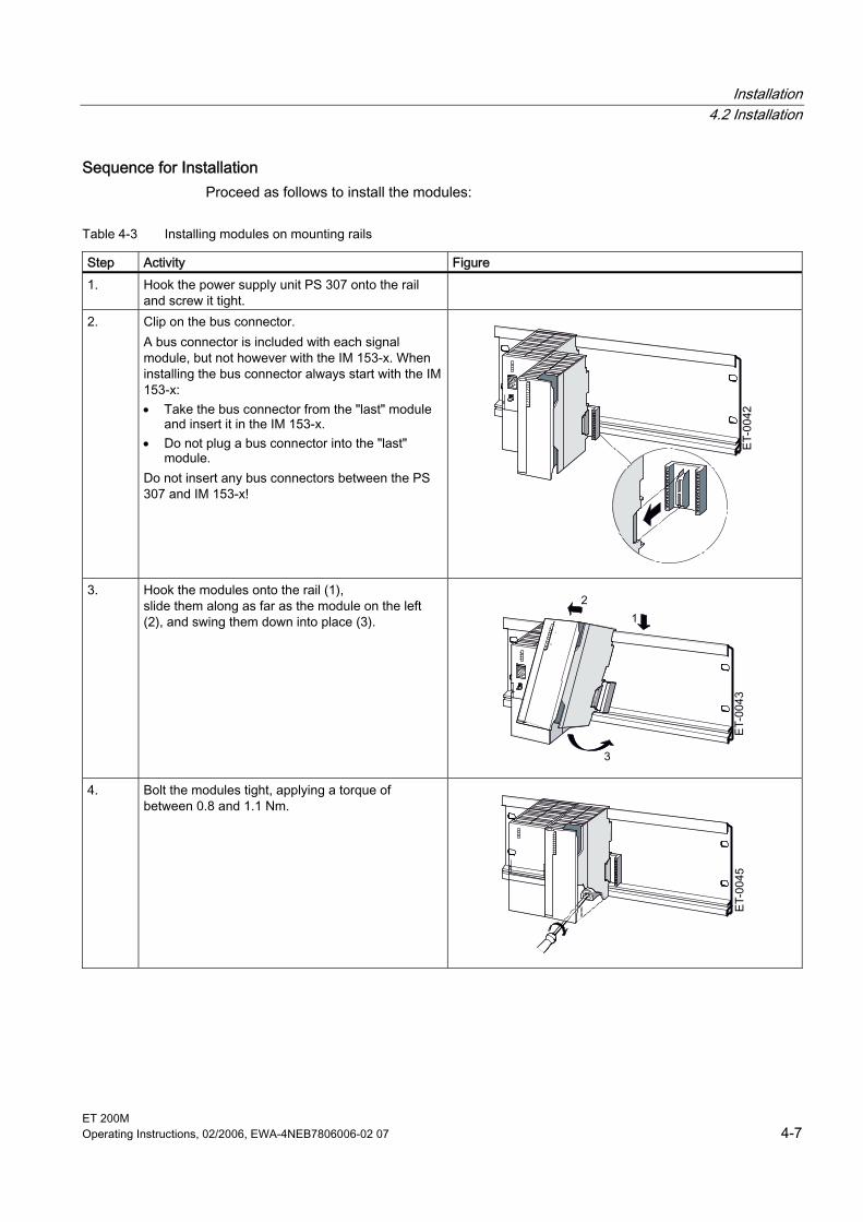
Installation 4.2 Installation
ET 200M Operating Instructions, 02/2006, EWA-4NEB7806006-02 07 4-7
Sequence for Installation Proceed as follows to install the modules:
Table 4-3 Installing modules on mounting rails
Step Activity Figure 1. Hook the power supply unit PS 307 onto the rail
and screw it tight.
2. Clip on the bus connector. A bus connector is included with each signal module, but not however with the IM 153-x. When installing the bus connector always start with the IM 153-x: • Take the bus connector from the "last" module
and insert it in the IM 153-x. • Do not plug a bus connector into the "last"
module. Do not insert any bus connectors between the PS 307 and IM 153-x!
3. Hook the modules onto the rail (1), slide them along as far as the module on the left (2), and swing them down into place (3).
4. Bolt the modules tight, applying a torque of between 0.8 and 1.1 Nm.
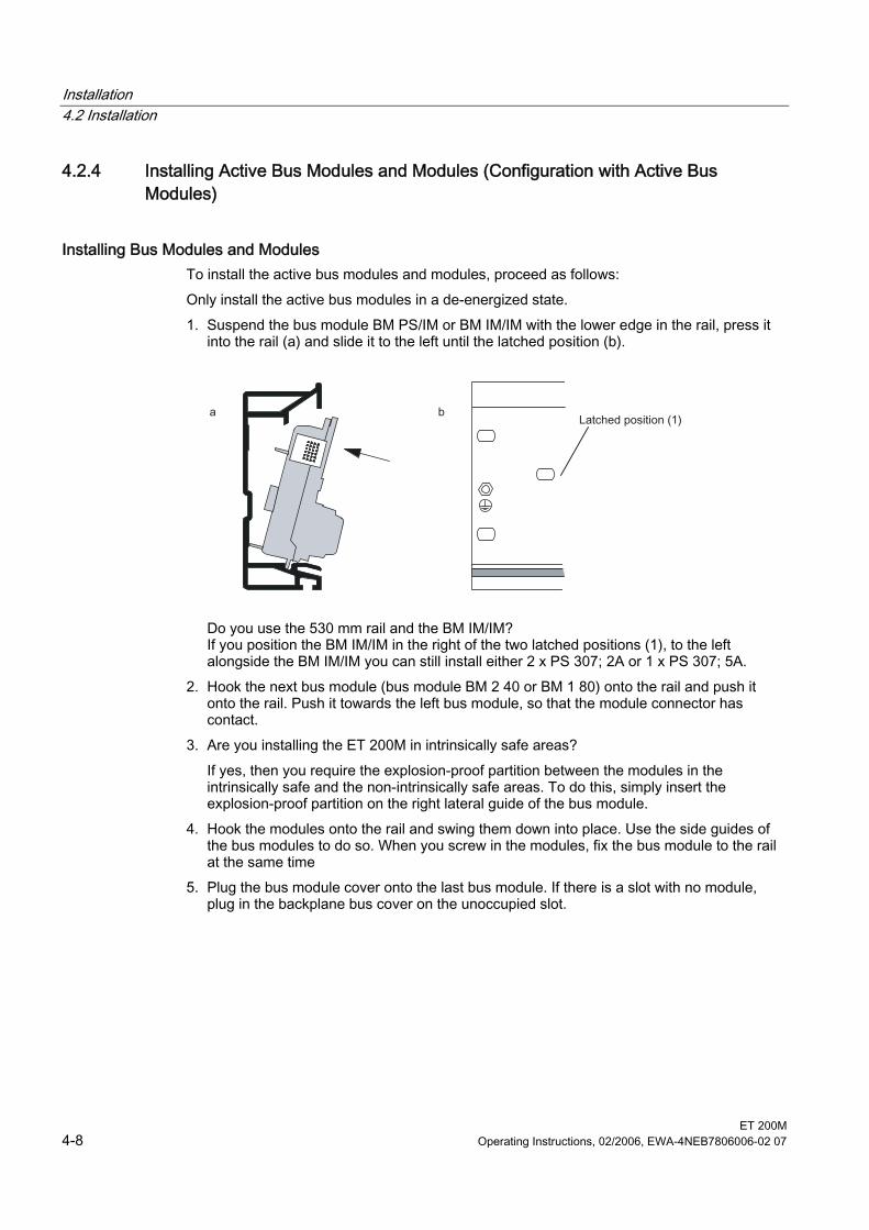
Installation 4.2 Installation
ET 200M 4-8 Operating Instructions, 02/2006, EWA-4NEB7806006-02 07
4.2.4 Installing Active Bus Modules and Modules (Configuration with Active Bus Modules)
Installing Bus Modules and Modules To install the active bus modules and modules, proceed as follows: Only install the active bus modules in a de-energized state. 1. Suspend the bus module BM PS/IM or BM IM/IM with the lower edge in the rail, press it
into the rail (a) and slide it to the left until the latched position (b).
Do you use the 530 mm rail and the BM IM/IM? If you position the BM IM/IM in the right of the two latched positions (1), to the left alongside the BM IM/IM you can still install either 2 x PS 307; 2A or 1 x PS 307; 5A.
2. Hook the next bus module (bus module BM 2 40 or BM 1 80) onto the rail and push it onto the rail. Push it towards the left bus module, so that the module connector has contact.
3. Are you installing the ET 200M in intrinsically safe areas? If yes, then you require the explosion-proof partition between the modules in the intrinsically safe and the non-intrinsically safe areas. To do this, simply insert the explosion-proof partition on the right lateral guide of the bus module.
4. Hook the modules onto the rail and swing them down into place. Use the side guides of the bus modules to do so. When you screw in the modules, fix the bus module to the rail at the same time
5. Plug the bus module cover onto the last bus module. If there is a slot with no module, plug in the backplane bus cover on the unoccupied slot.
Installation 4.2 Installation
ET 200M Operating Instructions, 02/2006, EWA-4NEB7806006-02 07 4-9
Plugging in Output Modules During Operation of an ET 200M Installation
Warning When you insert output modules, uncontrolled system states may occur. This also applies if you insert input/ output modules tilted on the bus module. When you insert an output module, the outputs set by the user program immediately become active. We recommend that you set the outputs in the user program to "0" when you remove an output module. If modules are removed and inserted incorrectly, neighboring modules may be affected via the backplane bus.
4.2.5 After installation
Assign slot numbers After installation you can assign a slot number to each module, and this makes it easier to assign the modules to the configuration table in STEP 7 or in COM PROFIBUS. The following table illustrates the assignment of the slots.
Table 4-4 Slot numbers for S7 modules
Slot number Module Remark 1 Power supply (PS) 1 – 2 IM 153-x – 3 – inapplicable 4 1. S7-300 module right alongside the IM 153-x 5 2. S7-300 module – … … – 11 8. S7-300 module –
1 The use of the power supply is optional.
Unoccupied slots If, in a configuration of an ET 200M with active bus modules, slots are unoccupied (e.g. reserved for later use), then you must leave these slots free in the configuration in STEP 7 or COM PROFIBUS!
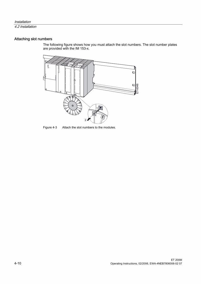
Installation 4.2 Installation
ET 200M 4-10 Operating Instructions, 02/2006, EWA-4NEB7806006-02 07
Attaching slot numbers The following figure shows how you must attach the slot numbers. The slot number plates are provided with the IM 153-x.
Figure 4-3 Attach the slot numbers to the modules.
Installation 4.3 Setting the PROFIBUS address
ET 200M Operating Instructions, 02/2006, EWA-4NEB7806006-02 07 4-11
4.3 4.3 Setting the PROFIBUS address
Definition Each bus node must receive a PROFIBUS address to identify it uniquely on the PROFIBUS DP.
Controlling The following rules apply for the PROFIBUS address of the IM 153-x: • Permissible PROFIBUS addresses are: 1 to 125. • Each PROFIBUS address can be allocated only once on the bus.
Setting the PROFIBUS Address 1. Set the PROFIBUS address using a screwdriver and with the door open.
The PROFIBUS address is the addition of the switch that is located on the right ("ON" position).
Note In the IM 153-2Bx00 and the IM 153-2Bxx1 the PROFIBUS address has an 8-pin DIL switch instead of the 7-pin switch that has been used up until now. The lowest switch has no function and is labeled with "0" or "-" in order to maintain the addition principle.
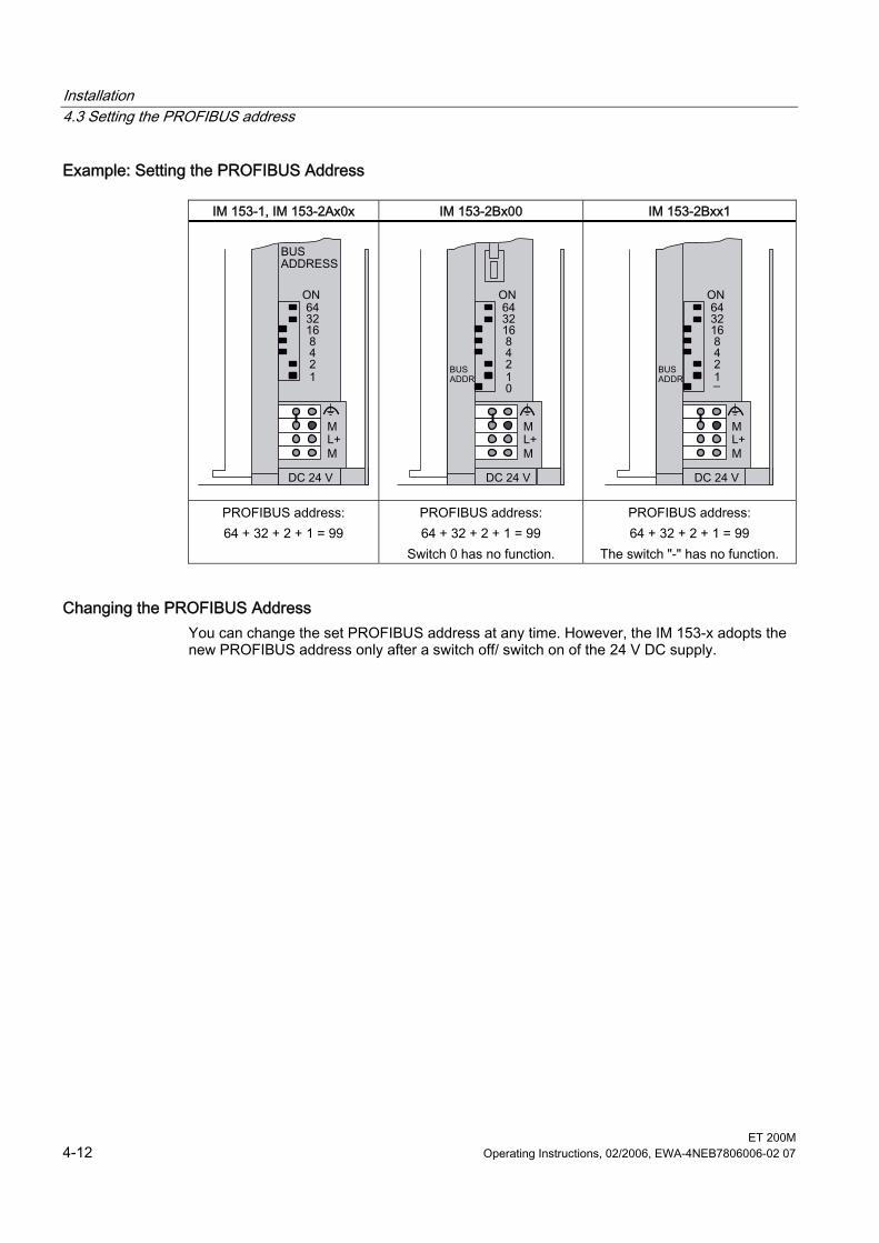
Installation 4.3 Setting the PROFIBUS address
ET 200M 4-12 Operating Instructions, 02/2006, EWA-4NEB7806006-02 07
Example: Setting the PROFIBUS Address
IM 153-1, IM 153-2Ax0x IM 153-2Bx00 IM 153-2Bxx1
PROFIBUS address: 64 + 32 + 2 + 1 = 99
PROFIBUS address: 64 + 32 + 2 + 1 = 99
Switch 0 has no function.
PROFIBUS address: 64 + 32 + 2 + 1 = 99
The switch "-" has no function.
Changing the PROFIBUS Address You can change the set PROFIBUS address at any time. However, the IM 153-x adopts the new PROFIBUS address only after a switch off/ switch on of the 24 V DC supply.
ET 200M Operating Instructions, 02/2006, EWA-4NEB7806006-02 07 5-1
Connecting 55.1 5.1 Overview
Introduction This chapter shows you how to wire an ET 200M. To set up an ET 200M, you must take into account the mechanical and electrical configuration. Information can be found in the Assignment Planning section.
Basic Rules In view of the many and varied applications of an ET 200M, this chapter can only describe a few basic rules on its electrical configuration. You must observe at least these basic rules if you want your ET 200M to operate faultlessly and satisfactorily.
PNO configuration guidelines With PROFIBUS networks, make sure you follow the PROFIBUS Nutzerorganisation (user organization) Installation Guidelines for PROFIBUS DP/FMS. These contain important information on cable routing and the commissioning of PROFIBUS networks. Publisher: PROFIBUS Nutzerorganisation e.V. Haid-und-Neu-Straße 7 76131 Karlsruhe Tel: +49 (721) 9658-590 Fax: +49 (721) 9658-589 Internet: http://www.profibus.com Guideline, order no. 2.112
Connecting 5.2 Connecting PROFIBUS DP
ET 200M 5-2 Operating Instructions, 02/2006, EWA-4NEB7806006-02 07
5.2 5.2 Connecting PROFIBUS DP
5.2.1 Connecting the Bus Connector
Applicable bus connectors To connect with the PROFIBUS DP it is preferable to use the following FastConnect bus connectors: • up to 12 MBaud, with vertical cable departure
– without PD jack (6ES7972-0BA50-0XA0) – with PD jack (6ES7972-0BB50-0XA0)
• up to 12 MBaud, with diagonal cable departure – without PD jack (6ES7972-0BA60-0XA0) – with PD jack (6ES7972-0BB60-0XA0)
These guarantee a fast and secure wiring with FC bus lines. Of course you can also continue to use the conventional bus connector with screw clamp connection: • up to 12 MBaud, with vertical cable departure
– without PD jack (6ES7972-0BA12-0XA0) – with PD jack (6ES7972-0BB12-0XA0)
• up to 12 MBaud, with diagonal cable departure – without PD jack (6ES7972-0BA41-0XA0) – with PD jack (6ES7972-0BB41-0XA0)
Connecting the Bus Connector Proceed as follows to connect the bus connector: 1. Plug the bus connector into the IM 153-x. 2. Tightly screw the bus connector into the IM 153-x. 3. If the bus connector is located at the start or end of a segment, you must connect the
terminating resistor (switch setting "ON"). Alternative: You use the PROFIBUS terminator as an active bus connector.
4. Lay the bus cable(s) in the area intended for the IM 153-x to the right alongside the DC 24 V connection terminal.
Ensure that the nodes to which the terminating resistor is connected are always supplied with voltage during power-up and operation.
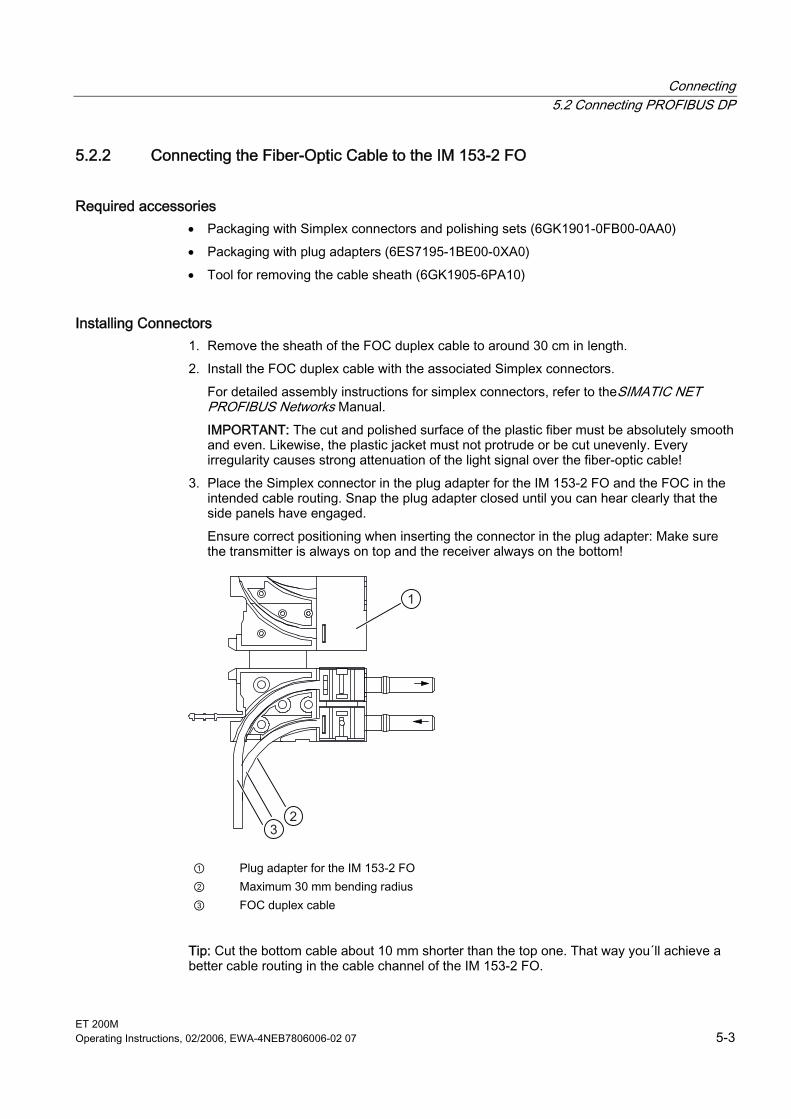
Connecting 5.2 Connecting PROFIBUS DP
ET 200M Operating Instructions, 02/2006, EWA-4NEB7806006-02 07 5-3
5.2.2 Connecting the Fiber-Optic Cable to the IM 153-2 FO
Required accessories • Packaging with Simplex connectors and polishing sets (6GK1901-0FB00-0AA0) • Packaging with plug adapters (6ES7195-1BE00-0XA0) • Tool for removing the cable sheath (6GK1905-6PA10)
Installing Connectors 1. Remove the sheath of the FOC duplex cable to around 30 cm in length. 2. Install the FOC duplex cable with the associated Simplex connectors.
For detailed assembly instructions for simplex connectors, refer to theSIMATIC NET PROFIBUS Networks Manual. IMPORTANT: The cut and polished surface of the plastic fiber must be absolutely smooth and even. Likewise, the plastic jacket must not protrude or be cut unevenly. Every irregularity causes strong attenuation of the light signal over the fiber-optic cable!
3. Place the Simplex connector in the plug adapter for the IM 153-2 FO and the FOC in the intended cable routing. Snap the plug adapter closed until you can hear clearly that the side panels have engaged. Ensure correct positioning when inserting the connector in the plug adapter: Make sure the transmitter is always on top and the receiver always on the bottom!
1
32
① Plug adapter for the IM 153-2 FO ② Maximum 30 mm bending radius ③ FOC duplex cable
Tip: Cut the bottom cable about 10 mm shorter than the top one. That way you´ll achieve a better cable routing in the cable channel of the IM 153-2 FO.
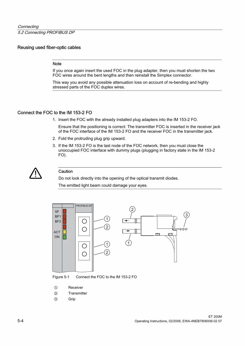
Connecting 5.2 Connecting PROFIBUS DP
ET 200M 5-4 Operating Instructions, 02/2006, EWA-4NEB7806006-02 07
Reusing used fiber-optic cables
Note If you once again insert the used FOC in the plug adapter, then you must shorten the two FOC wires around the bent lengths and then reinstall the Simplex connector. This way you avoid any possible attenuation loss on account of re-bending and highly stressed parts of the FOC duplex wires.
Connect the FOC to the IM 153-2 FO 1. Insert the FOC with the already installed plug adapters into the IM 153-2 FO.
Ensure that the positioning is correct: The transmitter FOC is inserted in the receiver jack of the FOC interface of the IM 153-2 FO and the receiver FOC in the transmitter jack.
2. Fold the protruding plug grip upward. 3. If the IM 153-2 FO is the last node of the FOC network, then you must close the
unoccupied FOC interface with dummy plugs (plugging in factory state in the IM 153-2 FO).
Caution
Do not look directly into the opening of the optical transmit diodes. The emitted light beam could damage your eyes.
1
23
2
1
2
1
Figure 5-1 Connect the FOC to the IM 153-2 FO
① Receiver ② Transmitter ③ Grip
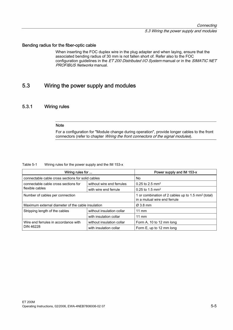
Connecting 5.3 Wiring the power supply and modules
ET 200M Operating Instructions, 02/2006, EWA-4NEB7806006-02 07 5-5
Bending radius for the fiber-optic cable When inserting the FOC duplex wire in the plug adapter and when laying, ensure that the associated bending radius of 30 mm is not fallen short of. Refer also to the FOC configuration guidelines in the ET 200 Distributed I/O System manual or in the SIMATIC NET PROFIBUS Networks manual.
5.3 5.3 Wiring the power supply and modules
5.3.1 Wiring rules
Note For a configuration for "Module change during operation", provide longer cables to the front connectors (refer to chapter Wiring the front connectors of the signal modules).
Table 5-1 Wiring rules for the power supply and the IM 153-x
Wiring rules for ... Power supply and IM 153-x connectable cable cross sections for solid cables No
without wire end ferrules 0.25 to 2.5 mm2 connectable cable cross sections for flexible cables with wire end ferrule 0.25 to 1.5 mm2 Number of cables per connection 1 or combination of 2 cables up to 1.5 mm2 (total)
in a mutual wire end ferrule Maximum external diameter of the cable insulation Ø 3.8 mm
without insulation collar 11 mm Stripping length of the cables with insulation collar 11 mm without insulation collar Form A, 10 to 12 mm long Wire end ferrules in accordance with
DIN 46228 with insulation collar Form E, up to 12 mm long
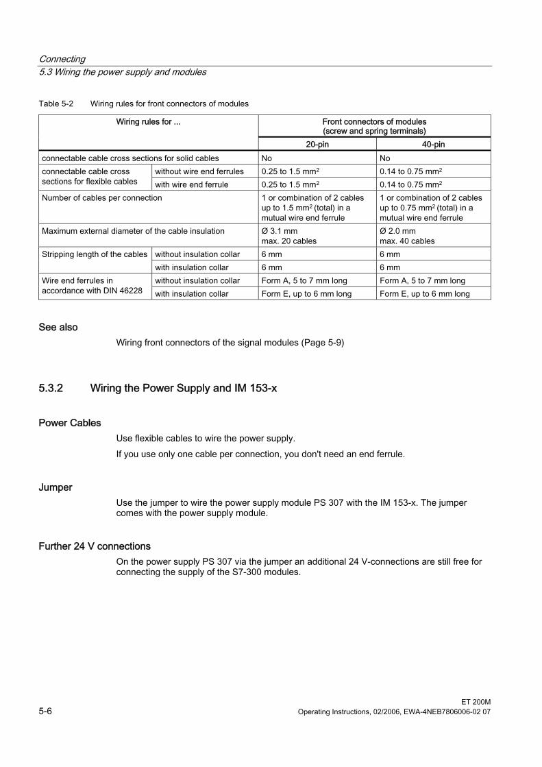
Connecting 5.3 Wiring the power supply and modules
ET 200M 5-6 Operating Instructions, 02/2006, EWA-4NEB7806006-02 07
Table 5-2 Wiring rules for front connectors of modules
Front connectors of modules (screw and spring terminals)
Wiring rules for ...
20-pin 40-pin connectable cable cross sections for solid cables No No
without wire end ferrules 0.25 to 1.5 mm2 0.14 to 0.75 mm2 connectable cable cross sections for flexible cables with wire end ferrule 0.25 to 1.5 mm2 0.14 to 0.75 mm2 Number of cables per connection 1 or combination of 2 cables
up to 1.5 mm2 (total) in a mutual wire end ferrule
1 or combination of 2 cables up to 0.75 mm2 (total) in a mutual wire end ferrule
Maximum external diameter of the cable insulation Ø 3.1 mm max. 20 cables
Ø 2.0 mm max. 40 cables
without insulation collar 6 mm 6 mm Stripping length of the cables with insulation collar 6 mm 6 mm without insulation collar Form A, 5 to 7 mm long Form A, 5 to 7 mm long Wire end ferrules in
accordance with DIN 46228 with insulation collar Form E, up to 6 mm long Form E, up to 6 mm long
See also Wiring front connectors of the signal modules (Page 5-9)
5.3.2 Wiring the Power Supply and IM 153-x
Power Cables Use flexible cables to wire the power supply. If you use only one cable per connection, you don't need an end ferrule.
Jumper Use the jumper to wire the power supply module PS 307 with the IM 153-x. The jumper comes with the power supply module.
Further 24 V connections On the power supply PS 307 via the jumper an additional 24 V-connections are still free for connecting the supply of the S7-300 modules.
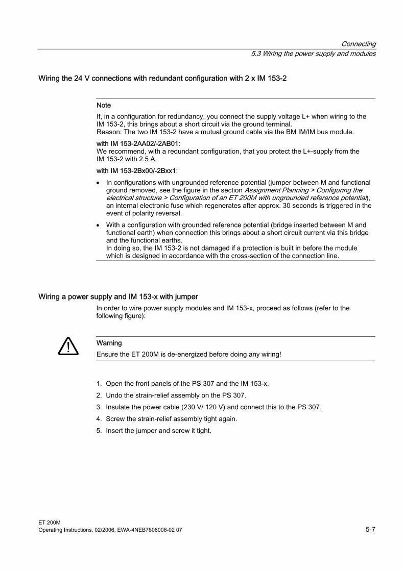
Connecting 5.3 Wiring the power supply and modules
ET 200M Operating Instructions, 02/2006, EWA-4NEB7806006-02 07 5-7
Wiring the 24 V connections with redundant configuration with 2 x IM 153-2
Note If, in a configuration for redundancy, you connect the supply voltage L+ when wiring to the IM 153-2, this brings about a short circuit via the ground terminal. Reason: The two IM 153-2 have a mutual ground cable via the BM IM/IM bus module. with IM 153-2AA02/-2AB01: We recommend, with a redundant configuration, that you protect the L+-supply from the IM 153-2 with 2.5 A. with IM 153-2Bx00/-2Bxx1: • In configurations with ungrounded reference potential (jumper between M and functional
ground removed, see the figure in the section Assignment Planning > Configuring the electrical structure > Configuration of an ET 200M with ungrounded reference potential), an internal electronic fuse which regenerates after approx. 30 seconds is triggered in the event of polarity reversal.
• With a configuration with grounded reference potential (bridge inserted between M and functional earth) when connection this brings about a short circuit current via this bridge and the functional earths. In doing so, the IM 153-2 is not damaged if a protection is built in before the module which is designed in accordance with the cross-section of the connection line.
Wiring a power supply and IM 153-x with jumper In order to wire power supply modules and IM 153-x, proceed as follows (refer to the following figure):
Warning Ensure the ET 200M is de-energized before doing any wiring!
1. Open the front panels of the PS 307 and the IM 153-x. 2. Undo the strain-relief assembly on the PS 307. 3. Insulate the power cable (230 V/ 120 V) and connect this to the PS 307. 4. Screw the strain-relief assembly tight again. 5. Insert the jumper and screw it tight.
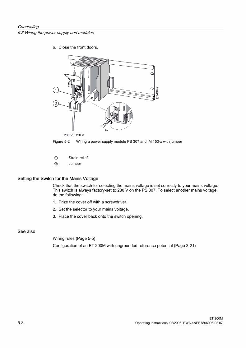
Connecting 5.3 Wiring the power supply and modules
ET 200M 5-8 Operating Instructions, 02/2006, EWA-4NEB7806006-02 07
6. Close the front doors.
1
2
Figure 5-2 Wiring a power supply module PS 307 and IM 153-x with jumper
① Strain-relief ② Jumper
Setting the Switch for the Mains Voltage Check that the switch for selecting the mains voltage is set correctly to your mains voltage. This switch is always factory-set to 230 V on the PS 307. To select another mains voltage, do the following: 1. Prize the cover off with a screwdriver. 2. Set the selector to your mains voltage. 3. Place the cover back onto the switch opening.
See also Wiring rules (Page 5-5) Configuration of an ET 200M with ungrounded reference potential (Page 3-21)
Connecting 5.3 Wiring the power supply and modules
ET 200M Operating Instructions, 02/2006, EWA-4NEB7806006-02 07 5-9
5.3.3 Wiring front connectors of the signal modules
S7-Ex-modules For information on how to wire the S7-Ex-modules and what you should observe when wiring modules in the intrinsically safe area, refer to the Distributed I/O Modules with Intrinsically-Safe Signals reference manual.
Cables You can use the flexible cables with cross-sections as specified in the section Wiring Rules. You do not need wire end ferrules. If you use wire end ferrules, only use such as are specified in the section Wiring Rules.
Types of Front Connector The 20-pin and 40-pin front connectors are available in 2 designs: Cage-clamp terminals and screw-type terminals. You can find the order numbers in the appendix Order Numbers for ET 200M.
Cageclamp Technology The front connectors in the cage-clamp technology can be wired very easily: Insert the screwdrivers vertically in the opening with the red opening mechanism, insert the cable in the associated terminal and then pull out the screwdriver. Tip: There is a separate opening for test probes up to 2 mm in diameter to the left of the opening for the screwdriver.
Wiring for Module Change During Operation If you wire modules for an ET 200M with the "module change during operation" function, you will require longer cables to the front connectors in order to easily insert and remove the modules during ET 200M operation. We recommend you make the wiring to the front connector approx. 20 cm longer.
Preparing the Connector for Wiring To prepare for wiring, proceed as follows:
Warning You can come into contact with live cables if the power supply module and possibly in addition the load power supplies are switched on. Ensure the ET 200M is de-energized before doing any wiring!
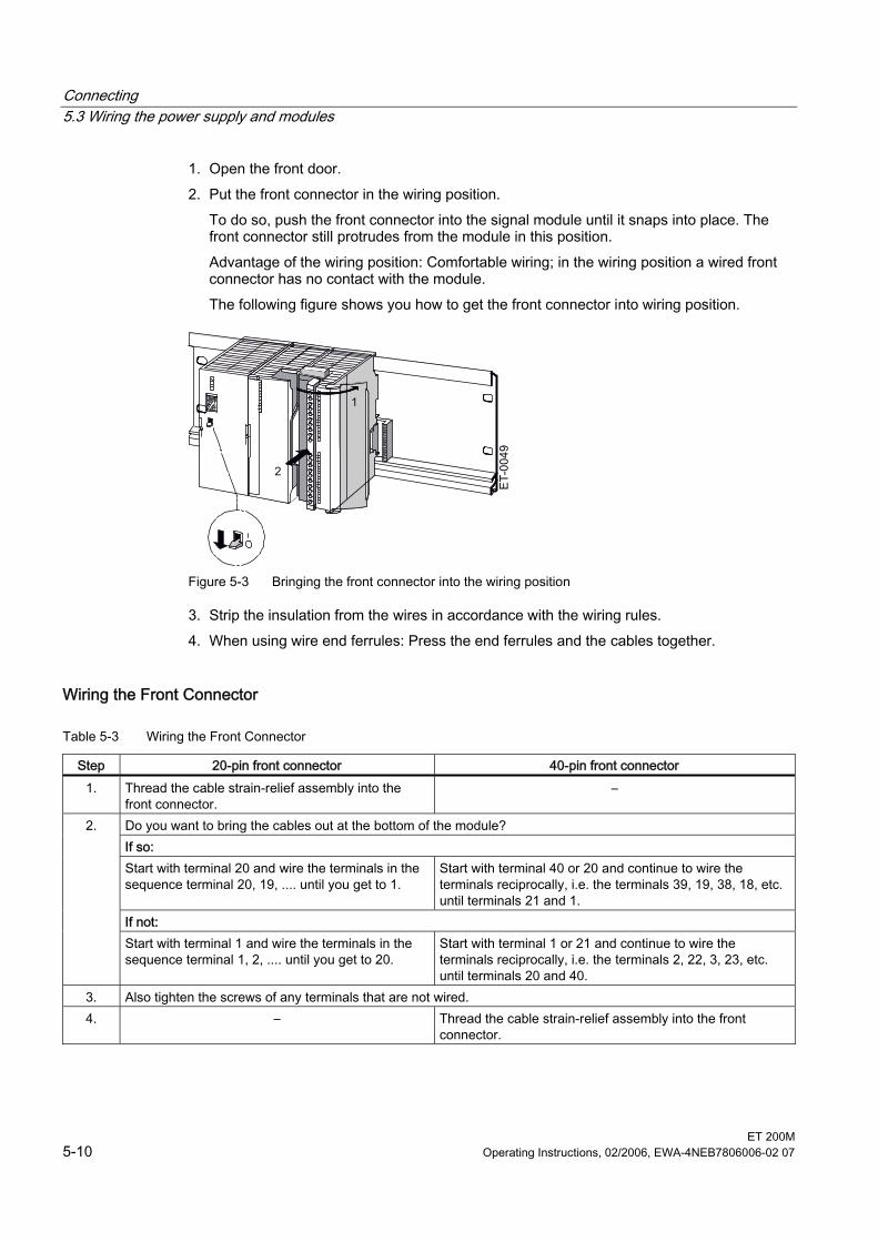
Connecting 5.3 Wiring the power supply and modules
ET 200M 5-10 Operating Instructions, 02/2006, EWA-4NEB7806006-02 07
1. Open the front door. 2. Put the front connector in the wiring position.
To do so, push the front connector into the signal module until it snaps into place. The front connector still protrudes from the module in this position. Advantage of the wiring position: Comfortable wiring; in the wiring position a wired front connector has no contact with the module. The following figure shows you how to get the front connector into wiring position.
ET-
0049
1
2
Figure 5-3 Bringing the front connector into the wiring position
3. Strip the insulation from the wires in accordance with the wiring rules. 4. When using wire end ferrules: Press the end ferrules and the cables together.
Wiring the Front Connector
Table 5-3 Wiring the Front Connector
Step 20-pin front connector 40-pin front connector 1. Thread the cable strain-relief assembly into the
front connector. –
Do you want to bring the cables out at the bottom of the module? If so: Start with terminal 20 and wire the terminals in the sequence terminal 20, 19, .... until you get to 1.
Start with terminal 40 or 20 and continue to wire the terminals reciprocally, i.e. the terminals 39, 19, 38, 18, etc. until terminals 21 and 1.
If not:
2.
Start with terminal 1 and wire the terminals in the sequence terminal 1, 2, .... until you get to 20.
Start with terminal 1 or 21 and continue to wire the terminals reciprocally, i.e. the terminals 2, 22, 3, 23, etc. until terminals 20 and 40.
3. Also tighten the screws of any terminals that are not wired. 4. – Thread the cable strain-relief assembly into the front
connector.
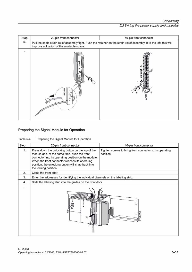
Connecting 5.3 Wiring the power supply and modules
ET 200M Operating Instructions, 02/2006, EWA-4NEB7806006-02 07 5-11
Step 20-pin front connector 40-pin front connector 5. Pull the cable strain-relief assembly tight. Push the retainer on the strain-relief assembly in to the left; this will
improve utilization of the available space. –
1
2
1
2
3 4
Preparing the Signal Module for Operation
Table 5-4 Preparing the Signal Module for Operation
Step 20-pin front connector 40-pin front connector 1. Press down the unlocking button on the top of the
module and, at the same time, push the front connector into its operating position on the module. When the front connector reaches its operating position, the unlocking button will snap back into the locking position.
Tighten screws to bring front connector to its operating position.
2. Close the front door. 3. Enter the addresses for identifying the individual channels on the labeling strip. 4. Slide the labeling strip into the guides on the front door. –
1
2
1a
Connecting 5.3 Wiring the power supply and modules
ET 200M 5-12 Operating Instructions, 02/2006, EWA-4NEB7806006-02 07
Note When the front connector is put in its operating position, a front connector encoding device engages. The front connector then only fits this type of module.
See also Wiring rules (Page 5-5)
5.3.4 Connecting shielded cables via a shield connecting element
Introduction This section tells you how to connect the shield of shielded signal lines to ground via a shield contact element. The connection to ground is achieved by direct contact between the shield contact element and the rail.
Application You can do the following easily with the shield contact element: • connecting all shielded lines from the S7-300 modules to ground • Connect the interconnecting cable to ground.
Design of the Shield Contact Element The shield contact element consists of the following parts: • a clamp with 2 screwed bolts for fixing to the rail
(order no.: 6ES7390-5AA00-0AA0) as well as • The shield terminals Depending on the cable cross-sections used, you must use the following shield terminal:
Table 5-5 Assignment of cable cross-sections and terminal elements
Cable and shield diameter Shield connection terminal order no.:
2 lines with in each case 2 to 6 mm shield diameter 6ES7390-5AB00-0AA0 1 line with 3 to 8 mm shield diameter 6ES7390-5BA00-0AA0 1 line with 4 to 13 mm shield diameter Bus cable
6ES7390-5CA00-0AA0
The shield contact element is 80 mm wide with space for two rows each with 4 shield terminals.
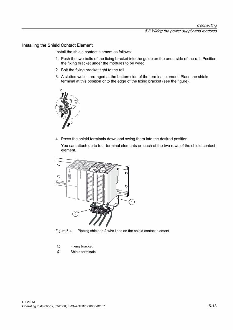
Connecting 5.3 Wiring the power supply and modules
ET 200M Operating Instructions, 02/2006, EWA-4NEB7806006-02 07 5-13
Installing the Shield Contact Element Install the shield contact element as follows: 1. Push the two bolts of the fixing bracket into the guide on the underside of the rail. Position
the fixing bracket under the modules to be wired. 2. Bolt the fixing bracket tight to the rail. 3. A slotted web is arranged at the bottom side of the terminal element. Place the shield
terminal at this position onto the edge of the fixing bracket (see the figure).
1
2
2
4. Press the shield terminals down and swing them into the desired position. You can attach up to four terminal elements on each of the two rows of the shield contact element.
1
2
Figure 5-4 Placing shielded 2-wire lines on the shield contact element
① Fixing bracket ② Shield terminals

Connecting 5.3 Wiring the power supply and modules
ET 200M 5-14 Operating Instructions, 02/2006, EWA-4NEB7806006-02 07
Attaching Cables You can only attach one or two shielded cables per shield terminal (see figure and table above). The cable is connected by its bare cable shield. There must be at least 20 mm of bare cable shield. If you need more than 4 shield terminals, start wiring at the rear row of the shield contact element.
Note Use a sufficiently long cable between the shield terminal and the front connector. This enables you to remove the front connector without removing the shield terminal.
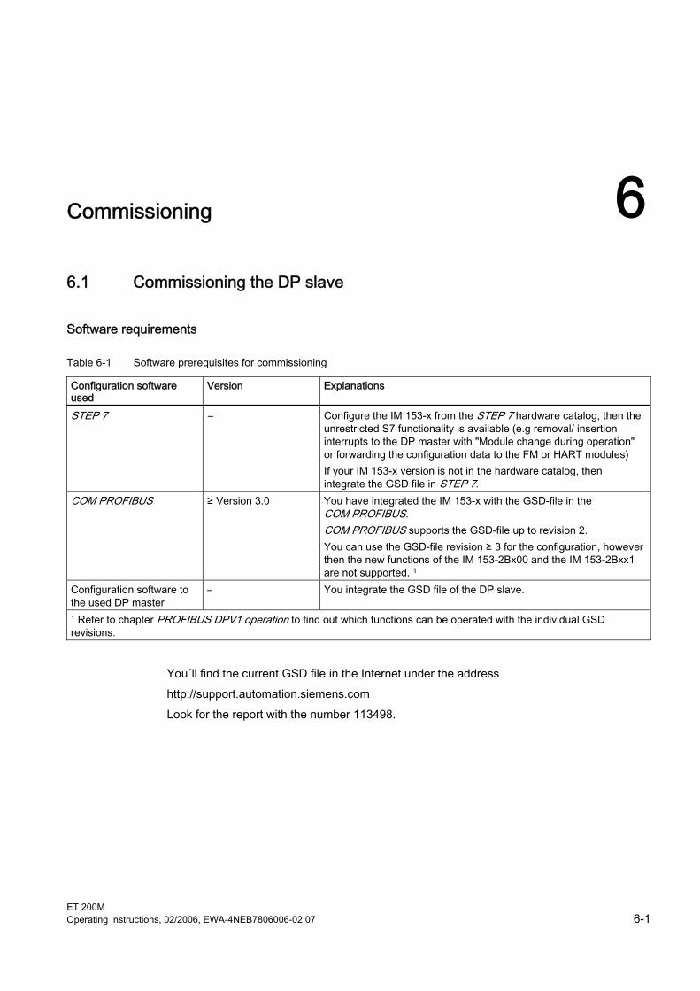
ET 200M Operating Instructions, 02/2006, EWA-4NEB7806006-02 07 6-1
Commissioning 66.1 6.1 Commissioning the DP slave
Software requirements
Table 6-1 Software prerequisites for commissioning
Configuration software used
Version Explanations
STEP 7 – Configure the IM 153-x from the STEP 7 hardware catalog, then the unrestricted S7 functionality is available (e.g removal/ insertion interrupts to the DP master with "Module change during operation" or forwarding the configuration data to the FM or HART modules) If your IM 153-x version is not in the hardware catalog, then integrate the GSD file in STEP 7.
COM PROFIBUS ≥ Version 3.0 You have integrated the IM 153-x with the GSD-file in the COM PROFIBUS. COM PROFIBUS supports the GSD-file up to revision 2. You can use the GSD-file revision ≥ 3 for the configuration, however then the new functions of the IM 153-2Bx00 and the IM 153-2Bxx1 are not supported. 1
Configuration software to the used DP master
– You integrate the GSD file of the DP slave.
1 Refer to chapter PROFIBUS DPV1 operation to find out which functions can be operated with the individual GSD revisions.
You´ll find the current GSD file in the Internet under the address http://support.automation.siemens.com Look for the report with the number 113498.
Commissioning 6.1 Commissioning the DP slave
ET 200M 6-2 Operating Instructions, 02/2006, EWA-4NEB7806006-02 07
Requirements for commissioning The following conditions must be fulfilled in order to commission the ET 200M: • DP slave installed • PROFIBUS address set on the DP slave • Bus connector or FOC is connected • Only for DP interface RS 485:
If the DP slave is located on the end of the segment, then the terminating resistor is switched on the DP slave.
• Only for the DP interface FOC: if the DP slave is located at the end of a FOC line, then the unused FOC interface must be closed with a dummy plug.
• DP slave configured (refer to the online help/ manual on configuration software)
Notice when configuring with GSD file When using an IM 153-2BA81 (outdoor) you must convert the user parameter "MLFB" to 6ES7153-2BA81-0XB0.
• Supply voltage for DP master switched on (refer to the DP master manual) • Configuration loaded into the DP master (refer to the online help/ manual on configuration
software) • DP master switched to RUN (refer to the DP master manual)
Commissioning the DP slave Commission the DP slave as follows: 1. Switch on the supply voltage for the DP slave. 2. If necessary, switch on the supply voltage for the load.
See also PROFIBUS DPV1 operation (Page 6-7)
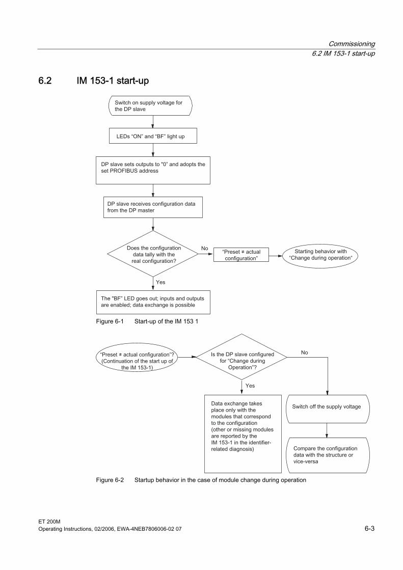
Commissioning 6.2 IM 153-1 start-up
ET 200M Operating Instructions, 02/2006, EWA-4NEB7806006-02 07 6-3
6.2 6.2 IM 153-1 start-up
Figure 6-1 Start-up of the IM 153 1
Figure 6-2 Startup behavior in the case of module change during operation
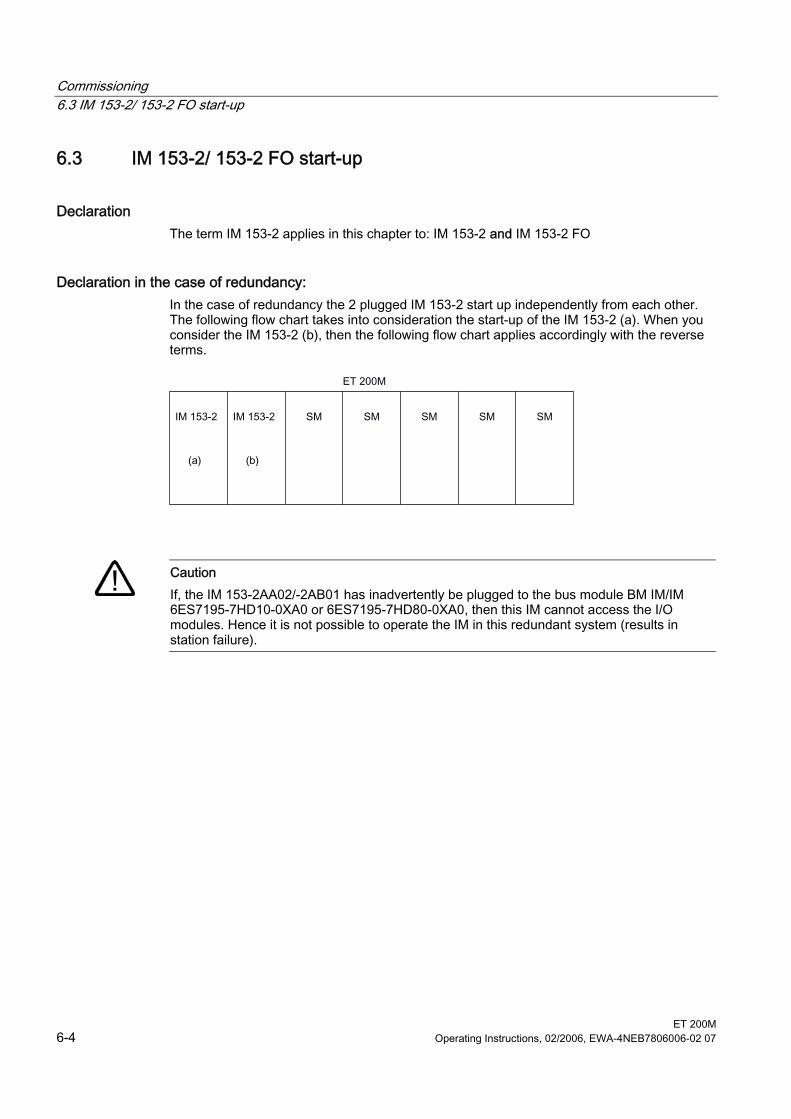
Commissioning 6.3 IM 153-2/ 153-2 FO start-up
ET 200M 6-4 Operating Instructions, 02/2006, EWA-4NEB7806006-02 07
6.3 6.3 IM 153-2/ 153-2 FO start-up
Declaration The term IM 153-2 applies in this chapter to: IM 153-2 and IM 153-2 FO
Declaration in the case of redundancy: In the case of redundancy the 2 plugged IM 153-2 start up independently from each other. The following flow chart takes into consideration the start-up of the IM 153-2 (a). When you consider the IM 153-2 (b), then the following flow chart applies accordingly with the reverse terms.
Caution If, the IM 153-2AA02/-2AB01 has inadvertently be plugged to the bus module BM IM/IM 6ES7195-7HD10-0XA0 or 6ES7195-7HD80-0XA0, then this IM cannot access the I/O modules. Hence it is not possible to operate the IM in this redundant system (results in station failure).
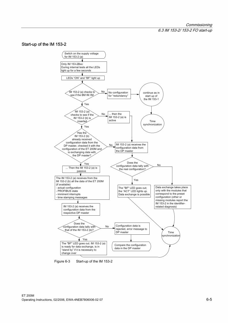
Commissioning 6.3 IM 153-2/ 153-2 FO start-up
ET 200M Operating Instructions, 02/2006, EWA-4NEB7806006-02 07 6-5
Start-up of the IM 153-2
Figure 6-3 Start-up of the IM 153-2
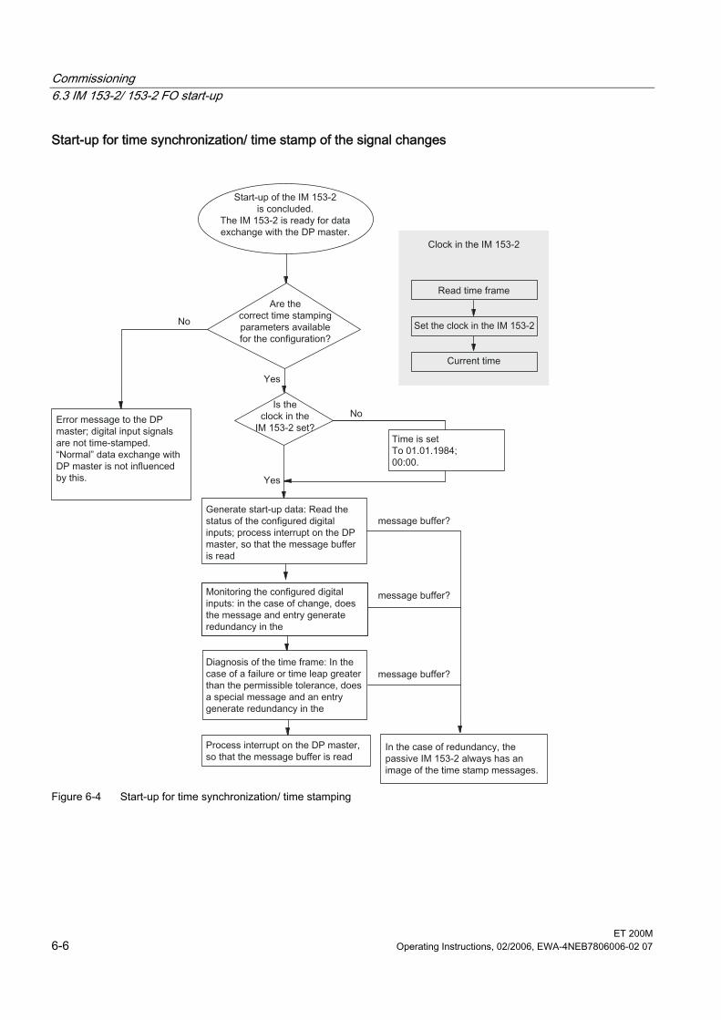
Commissioning 6.3 IM 153-2/ 153-2 FO start-up
ET 200M 6-6 Operating Instructions, 02/2006, EWA-4NEB7806006-02 07
Start-up for time synchronization/ time stamp of the signal changes
Figure 6-4 Start-up for time synchronization/ time stamping
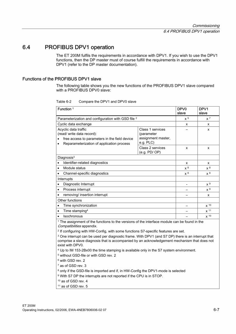
Commissioning 6.4 PROFIBUS DPV1 operation
ET 200M Operating Instructions, 02/2006, EWA-4NEB7806006-02 07 6-7
6.4 6.4 PROFIBUS DPV1 operation The ET 200M fulfils the requirements in accordance with DPV1. If you wish to use the DPV1 functions, then the DP master must of course fulfill the requirements in accordance with DPV1 (refer to the DP master documentation).
Functions of the PROFIBUS DPV1 slave The following table shows you the new functions of the PROFIBUS DPV1 slave compared with a PROFIBUS DPV0 slave:
Table 6-2 Compare the DPV1 and DPV0 slave
Function 1 DPV0 slave
DPV1 slave
Parameterization and configuration with GSD file 2 x 5 x 7 Cyclic data exchange x x
Class 1 services (parameter assignment master, e.g. PLC)
– x Acyclic data traffic (read/ write data record): • free access to parameters in the field device • Reparameterization of application process
Class 2 services (e.g. PD/ OP)
x x
Diagnosis3 • Identifier-related diagnostics x x • Module status x 6 x 8 • Channel-specific diagnostics x 6 x 8 Interrupts • Diagnostic Interrupt - x 9 • Process interrupt – x 9 • removing/ insertion interrupt – x Other functions • Time synchronization – x 10 • Time stamping4 – x 11 • Isochronous – x 10 1 The assignment of the functions to the versions of the interface module can be found in the Compatibilities appendix. 2 If configuring with HW-Config, with some functions S7-specific features are set. 3 One interrupt can be used per diagnostic frame. With DPV1 (and S7 DP) there is an interrupt that comprise a slave diagnosis that is accompanied by an acknowledgement mechanism that does not exist with DPV0. 4 Up to IM 153-2Bx00 the time stamping is available only in the S7 system environment. 5 without GSD-file or with GSD rev. 2 6 with GSD rev. 2 7 as of GSD rev. 3 8 only if the GSD-file is imported and if, in HW-Config the DPV1-mode is selected 9 With S7 DP the interrupts are not reported if the CPU is in STOP. 10 as of GSD rev. 4 11 as of GSD rev. 5
Commissioning 6.4 PROFIBUS DPV1 operation
ET 200M 6-8 Operating Instructions, 02/2006, EWA-4NEB7806006-02 07
Actions after the diagnostics message in the S7 or DPV1 mode Actions initiated by diagnostic messages: • With S7 or DPV1 operation the diagnoses are reported as diagnostic interrupts. • In DPV1 mode, diagnoses are also reported when the master CPU is in STOP. In the
diagnostic frame in addition the module status and the channel-related diagnoses are available.
• After a diagnostic message is signaled, the message is: – entered in the diagnostic frame as a diagnostic interrupt block (only one interrupt at
any one time) – stored in the diagnostics buffer of the master CPU
• The SF LED lights up on the IM 153-x. • The OB 82 is called in the master CPU. If the OB 82 is not available, then the master
CPU goes to STOP. • Acknowledging the diagnostic interrupt by the master CPU (a new diagnostic interrupt is
possible after this)
Actions after the diagnostics message in DPV0 mode The error is entered in the channel-specific diagnostics in the diagnostic frame: • The SF LED lights up on the IM 153-x. • Several simultaneous diagnostic messages are possible.
Faults and corrective measures The faults for diagnostic messages and possible corrective measures are described in chapter Interrupt, error and system messages > Structure of the diagnosis > Channel-specific diagnostics.
See also Compatibilities between the versions of IM 153 and IM 153-1 (Page A-1) Compatibilities between the versions of IM 153-2/-2 FO (Page A-3) Channel-specific diagnostics (Page 9-15)
ET 200M Operating Instructions, 02/2006, EWA-4NEB7806006-02 07 7-1
Maintenance and service 77.1 7.1 Wiring of the ET 200M
Scope of maintenance The ET 200M is a maintenance-free DP slave. Maintenance is limited to the replacement or exchanging of modules or components.
7.2 7.2 Replacing the Power Supply Module
Initial Situation The power supply module you want to replace is installed and wired. You want to install a new power supply module of the same type.
Slot numbering If you have provided the Power Supply Modules in your system with slot numbering, when replacing modules you must remove the numbering from the old Power Supply Modules and then reuse it in the new Power Supply Modules.
Removing the Power Supply Module To remove the power supply module, proceed as follows: 1. Operate the supply isolating switch in order to de-energize the power supply module. 2. Remove the cover. 3. Disconnect all the wiring. 4. Undo the fixing screws of the power supply module. 5. Swing the power supply module out.
Maintenance and service 7.3 replacing the IM 153-1
ET 200M 7-2 Operating Instructions, 02/2006, EWA-4NEB7806006-02 07
Installing the New Power Supply Module To install the new power supply module, proceed as follows: 1. Check the setting of the voltage selector switch. 2. Hook the new power supply module of the same type onto the rail and swing it down into
place. 3. Screw the power supply module on securely. 4. Wire the power supply module. 5. Connect the power supply module to the line voltage. 6. Close the cover.
Response of the ET 200M After Module Replacement If there is an error after replacing the module, with STEP 5 or STEP 7 you can view the cause of the error in the diagnostics buffer.
7.3 7.3 replacing the IM 153-1
Initial Situation The IM 153-1 is installed. A new IM 153-1 of the same type should be installed.
Slot numbering If you have provided the modules in your system with slot numbering, when replacing modules you must remove the numbering from the old module and then reuse it in the new module.
Pull out the bus connector You can remove the bus connector with worn-through bus cable from the PROFIBUS DP interface without having to interrupt the data traffic to the bus.
Note A data communication error may occur on the network. A bus segment must always be terminated at both ends with the terminating resistor. For example, this is not the case when the last slave with the bus connector is deactivated. As the terminating resistor in the bus connector obtains its voltage from the node, the function ofthe terminating resistor is affected. Ensure that the nodes to which the terminating resistor is connected are always supplied with voltage. Tip: Use the PROFIBUS terminator as an active bus connector.
Maintenance and service 7.4 Replacing the IM 153-2 or IM 153-2 FO
ET 200M Operating Instructions, 02/2006, EWA-4NEB7806006-02 07 7-3
Removing a Module To remove the module, proceed as follows: 1. Switch the on/ off switch of the power supply module to position 0 ( : output
voltages 0 V). 2. Tighten the bus connector. 3. Disconnect the wiring. 4. Loosen the fixing screws of the IM 153-1. 5. Swing out the IM 153-1.
Installing a New Module Install the new module as follows: 1. On the IM 153-1 set the same DP address as you had on the old IM 153-1. 2. Insert the new IM 153-1 and swing it down. 3. Screw the module on securely. 4. Wire the IM 153-1. 5. Screw the bus connector firmly into place. 6. Put the standby switch of the power supply module into the 1 position (output voltages to
rated value).
Response of the ET 200M After Module Replacement If there is a fault after replacing the module, with STEP 5 or STEP 7 in the diagnostics buffer you can view the cause of error.
7.4 7.4 Replacing the IM 153-2 or IM 153-2 FO
Initial Situation The IM 153-2/-2 FO is installed. A new IM 153-2/-2 FO of the same type should be installed.
Slot numbering If you have provided the modules in your system with slot numbering, when replacing modules you must remove the numbering from the old module and then reuse it in the new module.
Maintenance and service 7.4 Replacing the IM 153-2 or IM 153-2 FO
ET 200M 7-4 Operating Instructions, 02/2006, EWA-4NEB7806006-02 07
IM 153-2: Pull out the bus connector You can remove the bus connector with worn-through bus cable from the PROFIBUS DP interface without having to interrupt the data traffic to the bus.
Note A data communication error may occur on the network. On both ends, the bus segment must always be connected to the terminating resistor. For example, this is not the case when the last slave with the bus connector is deactivated. As the terminating resistor in the bus connector obtains its voltage from the node, the function ofthe terminating resistor is affected. Ensure that the nodes to which the terminating resistor is connected are always supplied with voltage. Tip: Use the PROFIBUS terminator as an active bus connector.
IM 153-2 FO: Removing the fiber-optic cable When you remove the FOC from the IM 153-2 FO, then all following DP slaves are also no longer available for the DP master!
Caution Do not look directly into the opening of the optical transmit diodes. The emitted light beam could damage your eyes.
Replacing In the redundant system
Note Always switch off the power before you replace the IM 153-2/-2 FO! If you carry out a replacement in an energized state, the specified switchover times cannot be guaranteed and the I/O modules could fail for a certain time and output "0".
If you replace the IM 153-2/-2 FO in a redundant configuration, the following applies:
"ACT" LED is on: "ACT" LED is off: The IM 153-2/-2 FO is the active one of the two IM 153-2/-2 FO.
The IM 153-2/-2 FO is the passive one of the two IM 153-2/-2 FO. This IM 153-2/-2 FO can be replaced without performing a switchover in the ET 200M.
Maintenance and service 7.4 Replacing the IM 153-2 or IM 153-2 FO
ET 200M Operating Instructions, 02/2006, EWA-4NEB7806006-02 07 7-5
Removing a Module To remove the module, proceed as follows: 1. In the Case of Redundancy: The IM 153-2/-2 FO that is to be replaced must always be
deactivated! Switch off the assigned power supply module or disconnect it on the IM 153-2/-2 FO.
Warning
If in redundant mode, the two IM 153-2 are connected to a power supply module, then when disconnecting the 24 V supply of an IM 153-2, this could bring about a short circuit of the non-insulated (loose) cable ends. In the event of a short circuit of the power supply, the second IM 153-2 and with that its ET 200M always fails completely. Therefore, when disconnecting the supply voltage, always work extremely carefully and insulate the two cable ends until you connect to the new IM 153-2.
No redundancy: Switch the on/ off switch of the power supply module to position 0 ( : output voltages 0 V).
2. Remove the bus connector or the FOC. In the case of fiber-optic cables: Fold out the handle for the plug adapter and with that remove the plug adapter from the IM 153-2 FO.
3. Disconnect the wiring. 4. Loosen the fixing screws of the IM 153-2/-2 FO. 5. Swing out the IM 153-2/-2 FO.
Installing a New Module Install the new module as follows: 1. On the IM 153-2/-2 FO, set the same DP address as you had on the old
IM 153-2/-2 FO. 2. Insert the new IM 153-2/-2 FO and swing it down. 3. Screw the module on securely. 4. Wire the IM 153-2/-2 FO. 5. Screw the bus connector firmly into place. 6. Put the standby switch of the power supply module into the 1 position (output voltages to
rated value).
Response of the ET 200M After Module Replacement If there is a fault after replacing the module, with STEP 5 or STEP 7 in the diagnostics buffer you can view the cause of error.
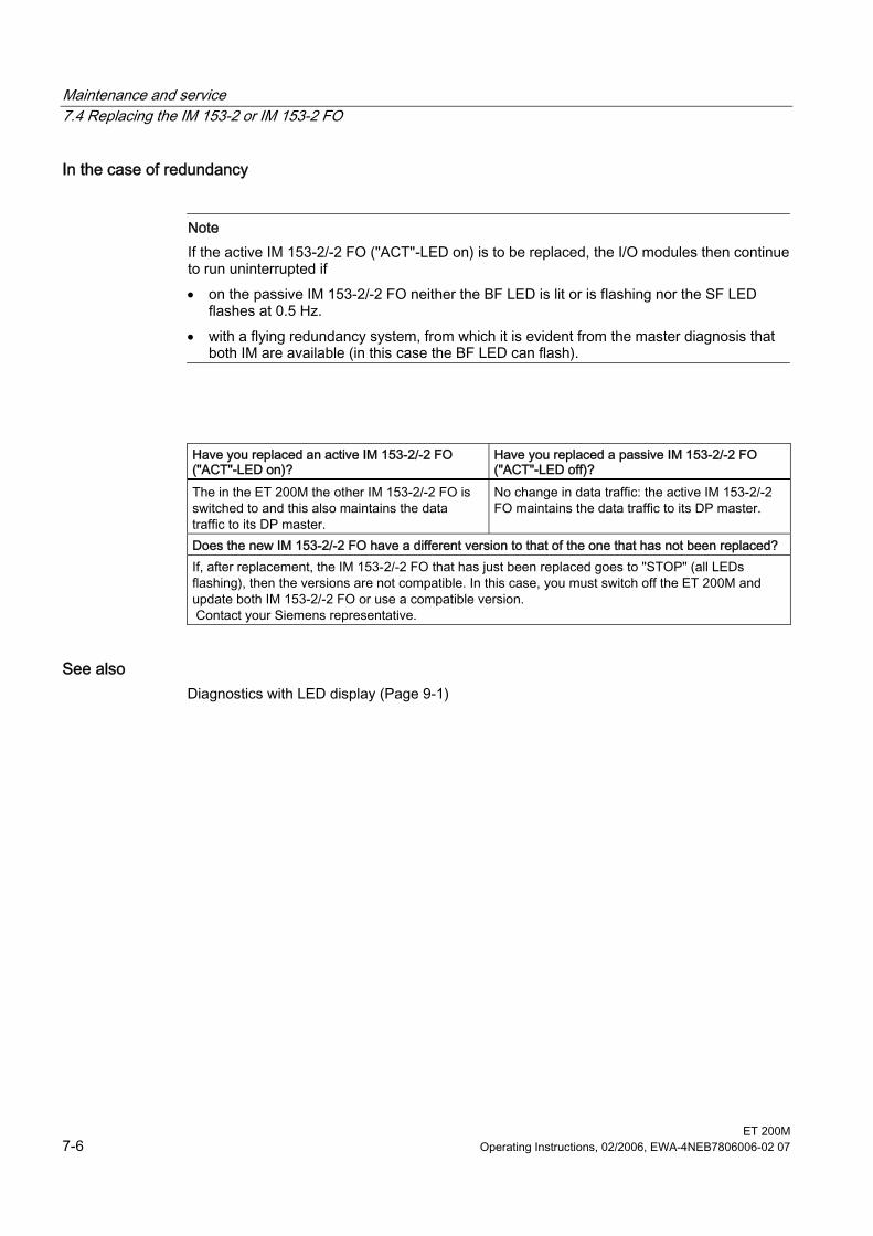
Maintenance and service 7.4 Replacing the IM 153-2 or IM 153-2 FO
ET 200M 7-6 Operating Instructions, 02/2006, EWA-4NEB7806006-02 07
In the case of redundancy
Note If the active IM 153-2/-2 FO ("ACT"-LED on) is to be replaced, the I/O modules then continue to run uninterrupted if • on the passive IM 153-2/-2 FO neither the BF LED is lit or is flashing nor the SF LED
flashes at 0.5 Hz. • with a flying redundancy system, from which it is evident from the master diagnosis that
both IM are available (in this case the BF LED can flash).
Have you replaced an active IM 153-2/-2 FO ("ACT"-LED on)?
Have you replaced a passive IM 153-2/-2 FO ("ACT"-LED off)?
The in the ET 200M the other IM 153-2/-2 FO is switched to and this also maintains the data traffic to its DP master.
No change in data traffic: the active IM 153-2/-2 FO maintains the data traffic to its DP master.
Does the new IM 153-2/-2 FO have a different version to that of the one that has not been replaced? If, after replacement, the IM 153-2/-2 FO that has just been replaced goes to "STOP" (all LEDs flashing), then the versions are not compatible. In this case, you must switch off the ET 200M and update both IM 153-2/-2 FO or use a compatible version. Contact your Siemens representative.
See also Diagnostics with LED display (Page 9-1)
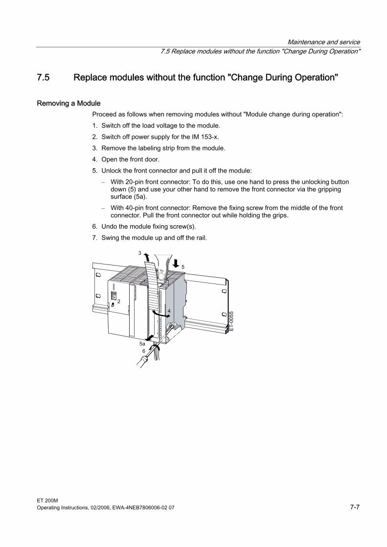
Maintenance and service 7.5 Replace modules without the function "Change During Operation"
ET 200M Operating Instructions, 02/2006, EWA-4NEB7806006-02 07 7-7
7.5 7.5 Replace modules without the function "Change During Operation"
Removing a Module Proceed as follows when removing modules without "Module change during operation": 1. Switch off the load voltage to the module. 2. Switch off power supply for the IM 153-x. 3. Remove the labeling strip from the module. 4. Open the front door. 5. Unlock the front connector and pull it off the module:
– With 20-pin front connector: To do this, use one hand to press the unlocking button down (5) and use your other hand to remove the front connector via the gripping surface (5a).
– With 40-pin front connector: Remove the fixing screw from the middle of the front connector. Pull the front connector out while holding the grips.
6. Undo the module fixing screw(s). 7. Swing the module up and off the rail.
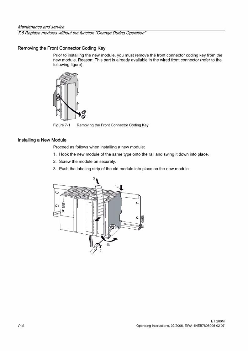
Maintenance and service 7.5 Replace modules without the function "Change During Operation"
ET 200M 7-8 Operating Instructions, 02/2006, EWA-4NEB7806006-02 07
Removing the Front Connector Coding Key Prior to installing the new module, you must remove the front connector coding key from the new module. Reason: This part is already available in the wired front connector (refer to the following figure).
Figure 7-1 Removing the Front Connector Coding Key
Installing a New Module Proceed as follows when installing a new module: 1. Hook the new module of the same type onto the rail and swing it down into place. 2. Screw the module on securely. 3. Push the labeling strip of the old module into place on the new module.
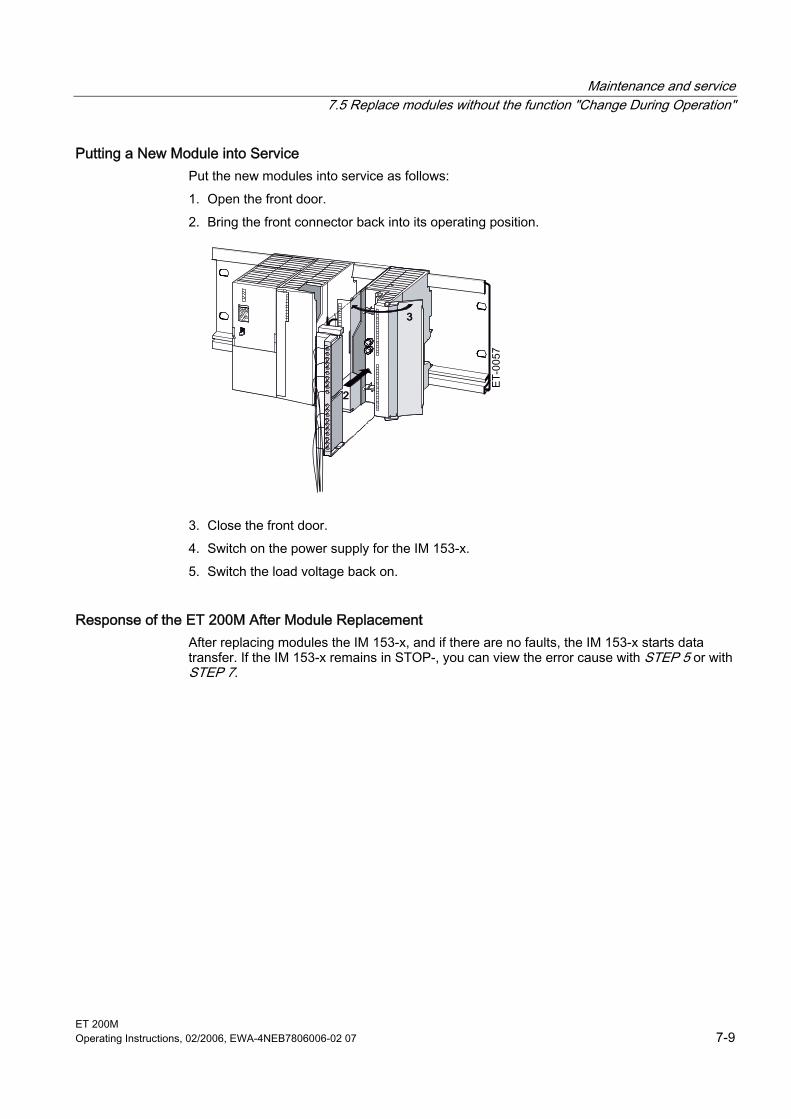
Maintenance and service 7.5 Replace modules without the function "Change During Operation"
ET 200M Operating Instructions, 02/2006, EWA-4NEB7806006-02 07 7-9
Putting a New Module into Service Put the new modules into service as follows: 1. Open the front door. 2. Bring the front connector back into its operating position.
3. Close the front door. 4. Switch on the power supply for the IM 153-x. 5. Switch the load voltage back on.
Response of the ET 200M After Module Replacement After replacing modules the IM 153-x, and if there are no faults, the IM 153-x starts data transfer. If the IM 153-x remains in STOP-, you can view the error cause with STEP 5 or with STEP 7.
Maintenance and service 7.6 Replace modules with the function "Change During Operation"
ET 200M 7-10 Operating Instructions, 02/2006, EWA-4NEB7806006-02 07
7.6 7.6 Replace modules with the function "Change During Operation"
Requirements You can replace the modules while operating the ET 200M if the ET 200M • on the rail with active bus modules for the function "Module Change During Operation" • and the ET 200M is configured for "Module Change During Operation".
Warning
Inserting output modules can lead to uncontrolled system states! This also applies if you insert input/ output modules tilted on the bus module. When inserting an output module, the outputs set by the user program become active immediately! We therefore advise you to set the outputs to "0" in the user program when removing the output module. If modules are not removed and inserted properly, neighboring modules via the backplane bus can fail.
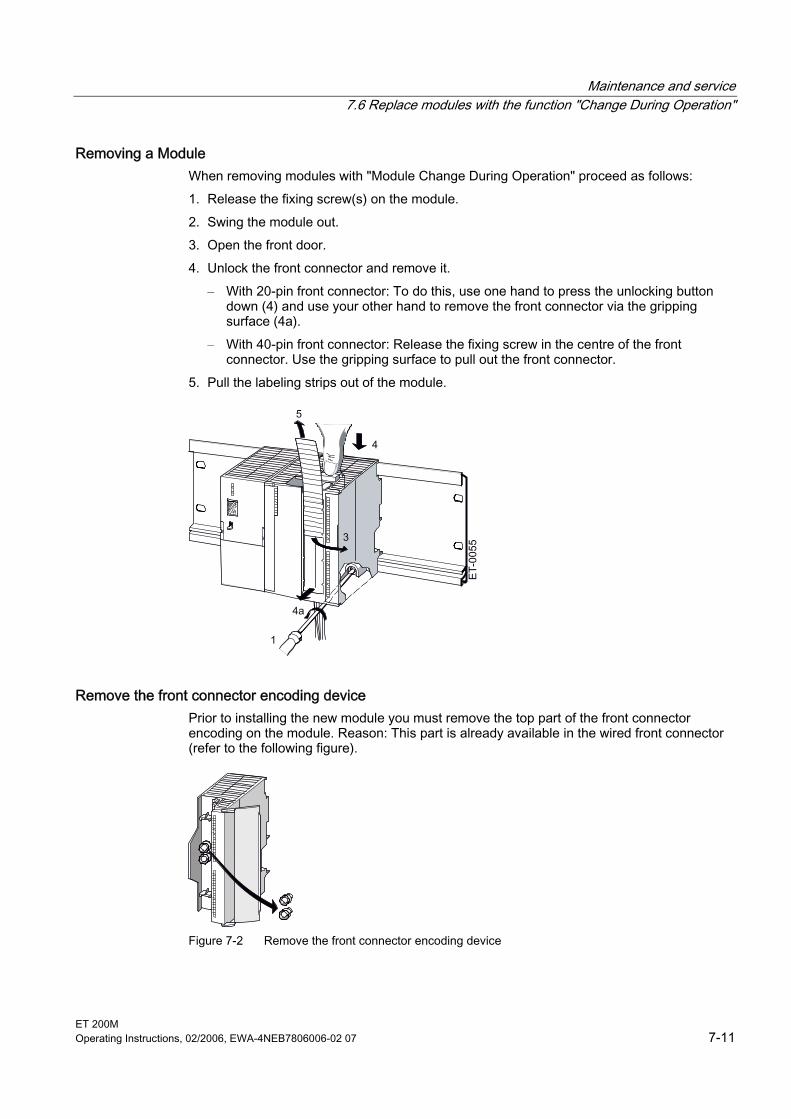
Maintenance and service 7.6 Replace modules with the function "Change During Operation"
ET 200M Operating Instructions, 02/2006, EWA-4NEB7806006-02 07 7-11
Removing a Module When removing modules with "Module Change During Operation" proceed as follows: 1. Release the fixing screw(s) on the module. 2. Swing the module out. 3. Open the front door. 4. Unlock the front connector and remove it.
– With 20-pin front connector: To do this, use one hand to press the unlocking button down (4) and use your other hand to remove the front connector via the gripping surface (4a).
– With 40-pin front connector: Release the fixing screw in the centre of the front connector. Use the gripping surface to pull out the front connector.
5. Pull the labeling strips out of the module.
Remove the front connector encoding device Prior to installing the new module you must remove the top part of the front connector encoding on the module. Reason: This part is already available in the wired front connector (refer to the following figure).
Figure 7-2 Remove the front connector encoding device
Maintenance and service 7.6 Replace modules with the function "Change During Operation"
ET 200M 7-12 Operating Instructions, 02/2006, EWA-4NEB7806006-02 07
Installing a New Module Proceed as follows to install a new module: 1. Insert the front connector in the module and put it in the operating position. 2. Suspend the new module and push it downwards. 3. Screw the module on securely. 4. Slide the labeling strips of the removed module into the newly installed module.
Response of the ET 200M after module replacement
Table 7-1 Response of the ET 200M when removing or inserting modules
Removing/ inserting
Actual = set configuration?
Response of the ET 200M
Removing a module
– The IM 153-x reports via diagnostics the removal of a module. The diagnostic event corresponds to the removal interrupt. The IM 153-x also enters the removal of a module in the module diagnosis.
Yes When inserting a configured module, the IM 153-x deletes the entry in the module diagnosis, so that the module is not addressed by the IM 153-x. If the ET 200M is in user data mode, then the IM 153-x reports a diagnostic event in accordance with the insertion interrupt. The inserted module is configured accordingly and assumed in the ET 200M. Any parameters for the module transferred from the user must then be transferred again from the user to the ET 200M.
Inserting a module
No The IM 153-x ignores the inserted module. The IM 153-x reports a diagnostic event in accordance with the insertion interrupt. In the diagnosis the entry remains after the module has been removed.
See also Identifier-related diagnosis (Page 9-13) Interrupts (Page 9-21)
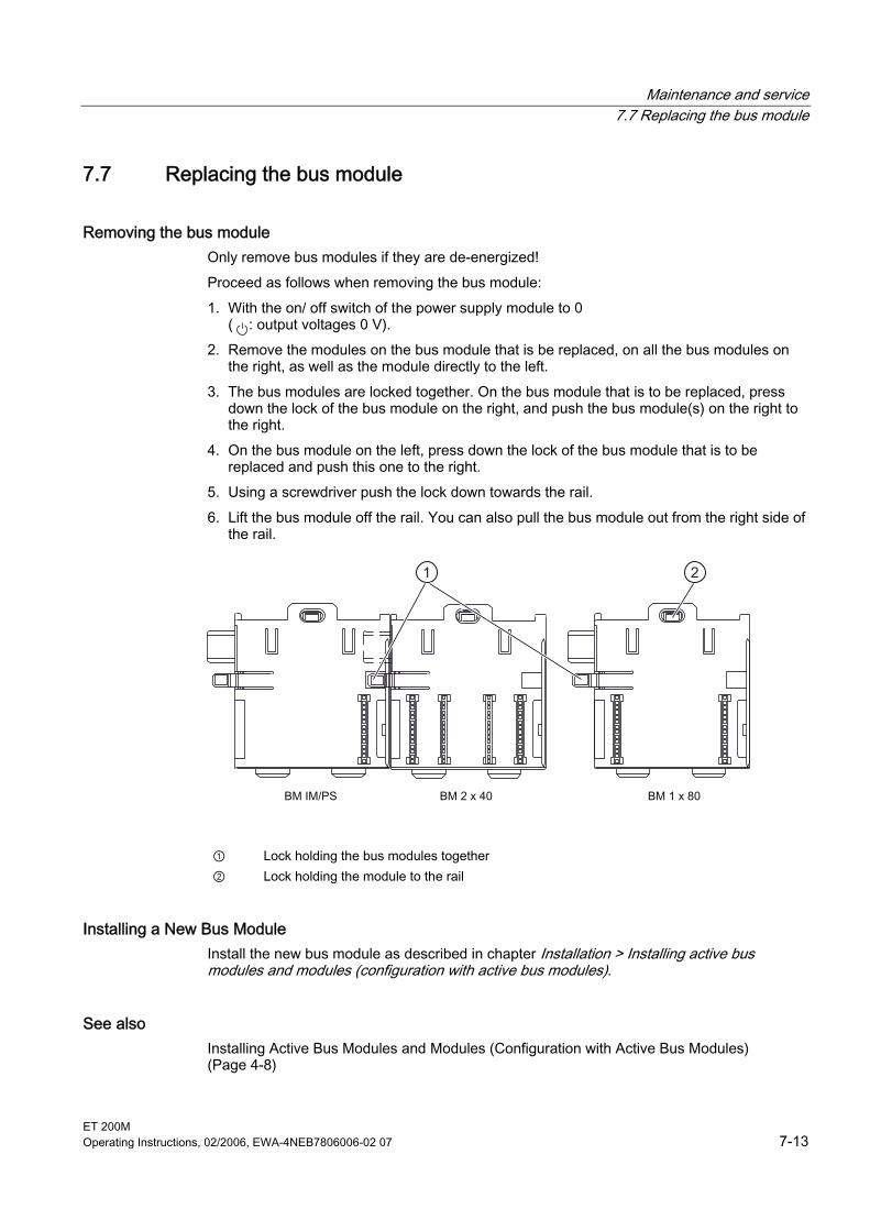
Maintenance and service 7.7 Replacing the bus module
ET 200M Operating Instructions, 02/2006, EWA-4NEB7806006-02 07 7-13
7.7 7.7 Replacing the bus module
Removing the bus module Only remove bus modules if they are de-energized! Proceed as follows when removing the bus module: 1. With the on/ off switch of the power supply module to 0
( : output voltages 0 V). 2. Remove the modules on the bus module that is be replaced, on all the bus modules on
the right, as well as the module directly to the left. 3. The bus modules are locked together. On the bus module that is to be replaced, press
down the lock of the bus module on the right, and push the bus module(s) on the right to the right.
4. On the bus module on the left, press down the lock of the bus module that is to be replaced and push this one to the right.
5. Using a screwdriver push the lock down towards the rail. 6. Lift the bus module off the rail. You can also pull the bus module out from the right side of
the rail.
① Lock holding the bus modules together ② Lock holding the module to the rail
Installing a New Bus Module Install the new bus module as described in chapter Installation > Installing active bus modules and modules (configuration with active bus modules).
See also Installing Active Bus Modules and Modules (Configuration with Active Bus Modules) (Page 4-8)
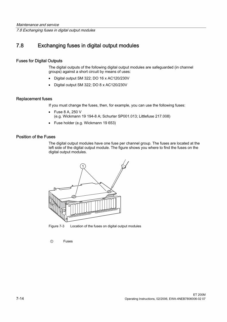
Maintenance and service 7.8 Exchanging fuses in digital output modules
ET 200M 7-14 Operating Instructions, 02/2006, EWA-4NEB7806006-02 07
7.8 7.8 Exchanging fuses in digital output modules
Fuses for Digital Outputs The digital outputs of the following digital output modules are safeguarded (in channel groups) against a short circuit by means of uses: • Digital output SM 322; DO 16 x AC120/230V • Digital output SM 322; DO 8 x AC120/230V
Replacement fuses If you must change the fuses, then, for example, you can use the following fuses: • Fuse 8 A, 250 V
(e.g. Wickmann 19 194-8 A; Schurter SP001.013; Littlefuse 217.008) • Fuse holder (e.g. Wickmann 19 653)
Position of the Fuses The digital output modules have one fuse per channel group. The fuses are located at the left side of the digital output module. The figure shows you where to find the fuses on the digital output modules.
1
Figure 7-3 Location of the fuses on digital output modules
① Fuses
Maintenance and service 7.9 Updating the IM 153-x
ET 200M Operating Instructions, 02/2006, EWA-4NEB7806006-02 07 7-15
Replacing Fuses The fuses are located at the left side of the module. 1. Disassemble the digital output modules as described in chapter Replace modules without
the function "Change During Operation" . 2. Remove the fuse holder from the digital output module. 3. Replace the fuse. 4. Screw the fuse holder back into the digital output module. 5. Disassemble the digital output modules as described in chapter Replace modules without
the function "Change During Operation" .
See also Replace modules without the function "Change During Operation" (Page 7-7)
7.9 7.9 Updating the IM 153-x
7.9.1 When should you update the IM 153-x? After performance or (compatible) function enhancements you should update the interface module IM 153-x to the latest firmware version.
7.9.2 Update of the IM 153-1/-2Ax0x Please contact your Siemens representative if you wish to update the IM 153-1 and the IM 153-2Ax0x.
7.9.3 Update of the IM 153-2Bx00
Where do you obtain the latest firmware version? The latest firmware versions can be obtained from your Siemens representative or from the Internet: http://support.automation.siemens.com Look for the report with the number 15350678. Tip: • Prior to the update note down the current version of your firmware. • If there are any problems with the latest firmware you can then still download the current
firmware from the Internet and transfer it to the interface module again.
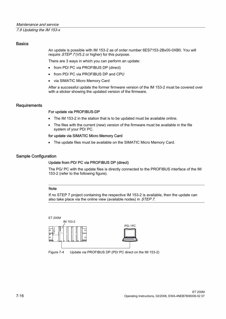
Maintenance and service 7.9 Updating the IM 153-x
ET 200M 7-16 Operating Instructions, 02/2006, EWA-4NEB7806006-02 07
Basics An update is possible with IM 153-2 as of order number 6ES7153-2Bx00-0XB0. You will require STEP 7 (V5.2 or higher) for this purpose. There are 3 ways in which you can perform an update: • from PD/ PC via PROFIBUS DP (direct) • from PD/ PC via PROFIBUS DP and CPU • via SIMATIC Micro Memory Card After a successful update the former firmware version of the IM 153-2 must be covered over with a sticker showing the updated version of the firmware.
Requirements For update via PROFIBUS-DP • The IM 153-2 in the station that is to be updated must be available online. • The files with the current (new) version of the firmware must be available in the file
system of your PD/ PC. for update via SIMATIC Micro Memory Card • The update files must be available on the SIMATIC Micro Memory Card.
Sample Configuration Update from PD/ PC via PROFIBUS DP (direct) The PG/ PC with the update files is directly connected to the PROFIBUS interface of the IM 153-2 (refer to the following figure).
Note If no STEP 7 project containing the respective IM 153-2 is available, then the update can also take place via the online view (available nodes) in STEP 7.
Figure 7-4 Update via PROFIBUS DP (PD/ PC direct on the IM 153-2)
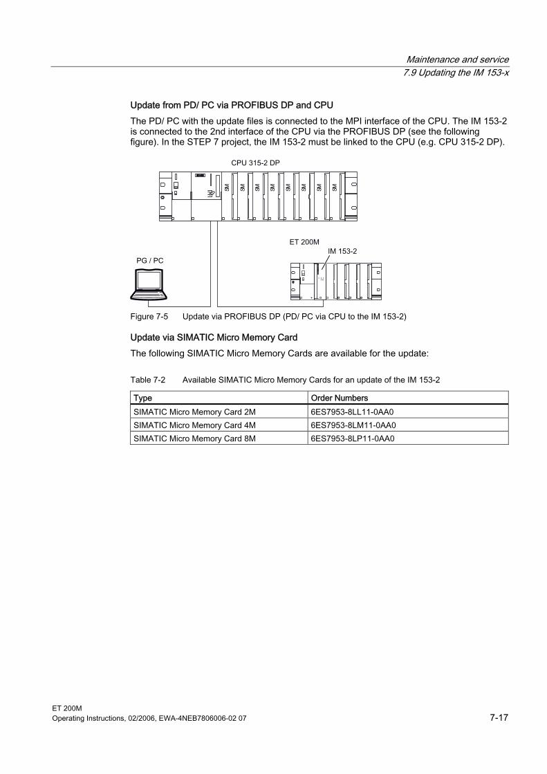
Maintenance and service 7.9 Updating the IM 153-x
ET 200M Operating Instructions, 02/2006, EWA-4NEB7806006-02 07 7-17
Update from PD/ PC via PROFIBUS DP and CPU The PD/ PC with the update files is connected to the MPI interface of the CPU. The IM 153-2 is connected to the 2nd interface of the CPU via the PROFIBUS DP (see the following figure). In the STEP 7 project, the IM 153-2 must be linked to the CPU (e.g. CPU 315-2 DP).
Figure 7-5 Update via PROFIBUS DP (PD/ PC via CPU to the IM 153-2)
Update via SIMATIC Micro Memory Card The following SIMATIC Micro Memory Cards are available for the update:
Table 7-2 Available SIMATIC Micro Memory Cards for an update of the IM 153-2
Type Order Numbers SIMATIC Micro Memory Card 2M 6ES7953-8LL11-0AA0 SIMATIC Micro Memory Card 4M 6ES7953-8LM11-0AA0 SIMATIC Micro Memory Card 8M 6ES7953-8LP11-0AA0
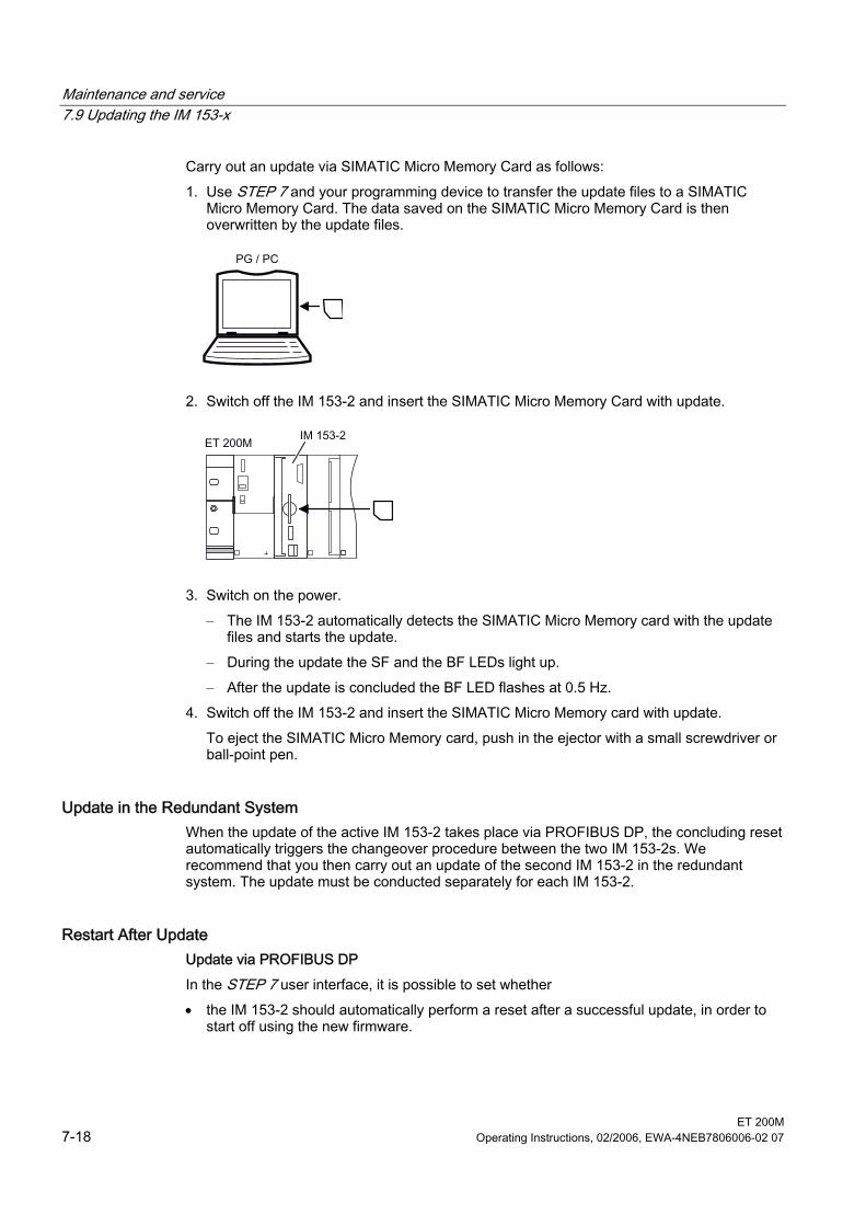
Maintenance and service 7.9 Updating the IM 153-x
ET 200M 7-18 Operating Instructions, 02/2006, EWA-4NEB7806006-02 07
Carry out an update via SIMATIC Micro Memory Card as follows: 1. Use STEP 7 and your programming device to transfer the update files to a SIMATIC
Micro Memory Card. The data saved on the SIMATIC Micro Memory Card is then overwritten by the update files.
2. Switch off the IM 153-2 and insert the SIMATIC Micro Memory Card with update.
3. Switch on the power. – The IM 153-2 automatically detects the SIMATIC Micro Memory card with the update
files and starts the update. – During the update the SF and the BF LEDs light up. – After the update is concluded the BF LED flashes at 0.5 Hz.
4. Switch off the IM 153-2 and insert the SIMATIC Micro Memory card with update. To eject the SIMATIC Micro Memory card, push in the ejector with a small screwdriver or ball-point pen.
Update in the Redundant System When the update of the active IM 153-2 takes place via PROFIBUS DP, the concluding reset automatically triggers the changeover procedure between the two IM 153-2s. We recommend that you then carry out an update of the second IM 153-2 in the redundant system. The update must be conducted separately for each IM 153-2.
Restart After Update Update via PROFIBUS DP In the STEP 7 user interface, it is possible to set whether • the IM 153-2 should automatically perform a reset after a successful update, in order to
start off using the new firmware.
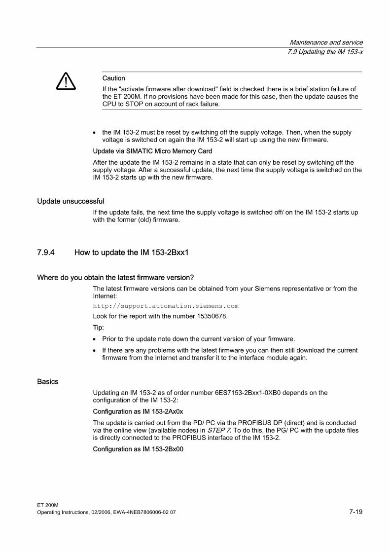
Maintenance and service 7.9 Updating the IM 153-x
ET 200M Operating Instructions, 02/2006, EWA-4NEB7806006-02 07 7-19
Caution
If the "activate firmware after download" field is checked there is a brief station failure of the ET 200M. If no provisions have been made for this case, then the update causes the CPU to STOP on account of rack failure.
• the IM 153-2 must be reset by switching off the supply voltage. Then, when the supply voltage is switched on again the IM 153-2 will start up using the new firmware.
Update via SIMATIC Micro Memory Card After the update the IM 153-2 remains in a state that can only be reset by switching off the supply voltage. After a successful update, the next time the supply voltage is switched on the IM 153-2 starts up with the new firmware.
Update unsuccessful If the update fails, the next time the supply voltage is switched off/ on the IM 153-2 starts up with the former (old) firmware.
7.9.4 How to update the IM 153-2Bxx1
Where do you obtain the latest firmware version? The latest firmware versions can be obtained from your Siemens representative or from the Internet: http://support.automation.siemens.com Look for the report with the number 15350678. Tip: • Prior to the update note down the current version of your firmware. • If there are any problems with the latest firmware you can then still download the current
firmware from the Internet and transfer it to the interface module again.
Basics Updating an IM 153-2 as of order number 6ES7153-2Bxx1-0XB0 depends on the configuration of the IM 153-2: Configuration as IM 153-2Ax0x The update is carried out from the PD/ PC via the PROFIBUS DP (direct) and is conducted via the online view (available nodes) in STEP 7. To do this, the PG/ PC with the update files is directly connected to the PROFIBUS interface of the IM 153-2. Configuration as IM 153-2Bx00
Maintenance and service 7.9 Updating the IM 153-x
ET 200M 7-20 Operating Instructions, 02/2006, EWA-4NEB7806006-02 07
There are 2 ways in which you can perform an update: • from PD/ PC via PROFIBUS DP (direct) • from PD/ PC via PROFIBUS DP and CPU You will require STEP 7 (V5.2 or higher) Configuration as IM 153-2Bxx1 There are 2 ways in which you can perform an update: • from PD/ PC via PROFIBUS DP (direct) • from PD/ PC via PROFIBUS DP and CPU You will require STEP 7 (V5.4 or higher) After a successful update the former firmware version of the IM 153-2 must be covered over with a sticker showing the updated version of the firmware. With the interface modules IM 153-2Bxx1-0XB0 it is possible to update the firmware of both interface modules while the redundant mode is running. The update takes place with support from STEP 7 and has no interaction on the running application. The firmware in a redundant system is updated from the PD/ PC via PROFIBUS DP (direct).
Conditions for an update via PROFIBUS DP • The IM 153-2 in the station that is to be updated must be available online. • The files with the current (new) version of the firmware must be available in the file
system of your PD/ PC. You must also comply with the following conditions in order to update a redundant system: • Both interface modules are IM 153-2Bxx1-0XB0 and are configured as such. • The station with redundant IM 153-2 is run
– at S7-400H – with software redundancy with DPV1 mode – on any redundant DP masters with GSD as of rev. 5
An update, supported by STEP 7, of both interface modules in a redundant system is not possible if • an IM 153-2 in the station is using an older version • the interface module IM 153-2Bxx1-0XB0 is being used as a spare part for older versions
(e.g.-2AA02-)
Sample Configuration See above under Update of the IM 153-2Bx00
Restart After Update In the STEP 7 user interface, it is possible to set whether • the IM 153-2 should automatically perform a reset after a successful update, in order to
start off using the new firmware.
Maintenance and service 7.9 Updating the IM 153-x
ET 200M Operating Instructions, 02/2006, EWA-4NEB7806006-02 07 7-21
Caution
If the "activate firmware after download" field is checked there is a brief station failure of the ET 200M. If no provisions have been made for this case, then the update causes the CPU to STOP on account of rack failure.
• the IM 153-2 must be reset by switching off the supply voltage. Then, when the supply voltage is switched on again the IM 153-2 will start up using the new firmware.
If the update concludes successfully, with the first reset or switch off/ on of the supply voltage, the start up of the interface module IM 153-2Bxx1 takes around 60 seconds longer than it would with a normal start up. All further start ups will take the usual time.
Update unsuccessful If the update fails, the next time the supply voltage is switched off/ on the IM 153-2 starts up with the former (old) firmware.

Maintenance and service 7.9 Updating the IM 153-x
ET 200M 7-22 Operating Instructions, 02/2006, EWA-4NEB7806006-02 07
ET 200M Operating Instructions, 02/2006, EWA-4NEB7806006-02 07 8-1
Functions 88.1 8.1 Time stamping the input signals with IM 153-2
8.1.1 Principles It is possible to time stamp with IM 153-2 • within an S7-400 automation system
– with STEP 7 whilst using the FB 62 (FB TIMESTMP) with 10 ms precision or as a highly precise time stamping with 1 ms precision (refer to the online help for STEP 7)
– with the PCS 7 system solution whilst using the FB 90 (FB IM_DRV) with 10 ms precision You´ll find a detailed description for time stamping with 10 ms precision and for time synchronization in the PCS 7 function manual 10 ms-time stamping. You´ll find the function manual in the Internet under the address: http://support.automation.siemens.com Look for the report with the number 15231179.
• outside of an S7-400 automation system, with precisions of up to 1 ms
Controlling You can use the time stamping for selected input signals, and for those that are of relevance to your application. On an ET 200M, the input signals of maximum 128 digital inputs can be time stamped. For a better load distribution on the PROFIBUS DP and in the IM 153-2 we recommend distributing these signals if necessary over several IM 153-2.
Marginal conditions The precision of the time stamping is influenced by the following marginal conditions: • The number of time-stamped input signals in an ET 200M influences the precision of the
time stamping, e.g. more time-stamped input signals reduce the precision of the time stamping.
• Process interrupts as well as reading/ writing data records reduce the precision of the time stamping. The specified precisions for time stamping (10 ms or 1 ms) will however remain.
• In the case of synchronous operation, the precision of the time stamping always corresponds to the DP cycle time.
Functions 8.1 Time stamping the input signals with IM 153-2
ET 200M 8-2 Operating Instructions, 02/2006, EWA-4NEB7806006-02 07
Operating principle The IM 153-2 provides changed input signals with the respective current time and saves this in a buffer (message list). Such a message list is a data record with maximum 20 messages about time-stamped signal changes. Up to 15 data records can be saved in the IM 153-2. A signal message provides the following information: • Slot number of the (reported) DI module (4 ... 11) • Channel number of the DI module • Signal status (incoming, outgoing) • Time of the signal change When there are time-stamped signals or a data record is full, the IM 153-2 generates a process interrupt to the DP master. The buffer is evaluated with "read data record". In the case of events that influence the time stamping (STOP of the time stamping, time message frame failure, ...) special messages are generated. A special message provides the following information: • Slot number of the IM 153-2 (always "2") • Code of the special message (e.g. STOP of the time stamping) • Characteristic of the special message (e.g. incoming/ outgoing) • Time of the special message
Parameterization With the configuration you establish which digital input data of the IM 153-2 is going to be monitored. For the time stamping, these are signal changes on the digital inputs. Two signal edges are always stamped. In doing so, the following assignment can be configured: • "rising edge" (0 → 1) as "incoming signal"
As a result, the "falling edge" (1 → 0) is the "outgoing signal". • "falling edge" (1 → 0) as "incoming signal"
As a result, the "rising edge" (0 → 1) is the "outgoing signal".
Note There are no parameters for setting the time stamping precision. To achieve the respective precision however, the specified conditions and rules must be complied with.
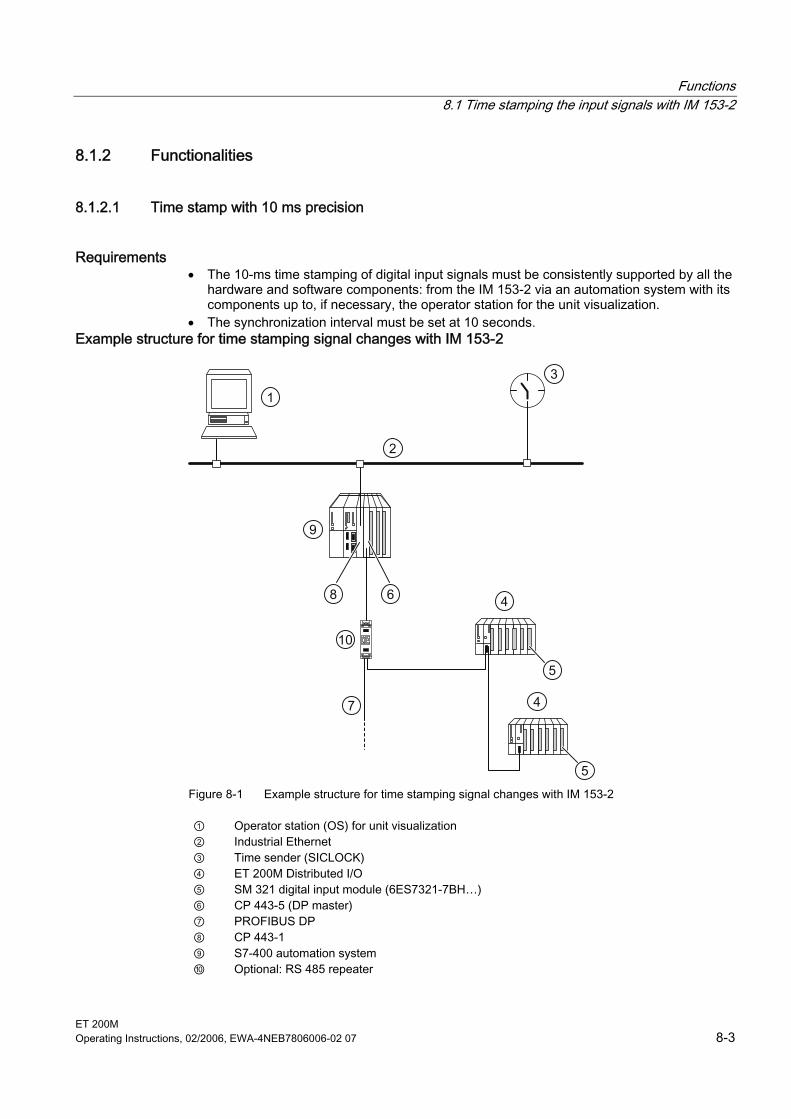
Functions 8.1 Time stamping the input signals with IM 153-2
ET 200M Operating Instructions, 02/2006, EWA-4NEB7806006-02 07 8-3
8.1.2 Functionalities
8.1.2.1 Time stamp with 10 ms precision
Requirements • The 10-ms time stamping of digital input signals must be consistently supported by all the
hardware and software components: from the IM 153-2 via an automation system with its components up to, if necessary, the operator station for the unit visualization.
• The synchronization interval must be set at 10 seconds. Example structure for time stamping signal changes with IM 153-2
10
1
2
3
4
5
4
5
6
7
8
9
Figure 8-1 Example structure for time stamping signal changes with IM 153-2
① Operator station (OS) for unit visualization ② Industrial Ethernet ③ Time sender (SICLOCK) ④ ET 200M Distributed I/O ⑤ SM 321 digital input module (6ES7321-7BH…) ⑥ CP 443-5 (DP master) ⑦ PROFIBUS DP ⑧ CP 443-1 ⑨ S7-400 automation system ⑩ Optional: RS 485 repeater

Functions 8.1 Time stamping the input signals with IM 153-2
ET 200M 8-4 Operating Instructions, 02/2006, EWA-4NEB7806006-02 07
8.1.2.2 Highly precise time stamp with 1 ms precision
Controlling The following configuration must be authorized for the highly precise time stamping with 1 ms precision: • Automation system with highly precise time synchronization
To do this a clock master, e.g. SICLOCK TM must be available in the automation system. • ET 200M with IM 153-2 (as of 6ES7153-2BAx1-0XB0) • no RS 485 repeater between the DP master and the ET 200M on which input signals are
to be time stamped • Only digital input modules can be used in the ET 200M. • Only signals from the DI module 6ES7321-7BHxx-0AB0 can be time stamped.
– The input delay of all digital inputs for time stamping must be configured identical to the minimum value (100 μs).
– Process interrupts must be deactivated. • Input signals that should receive a time stamp must be lined up as seamlessly as
possible as of slot 4, channel 0. • The start-up time of the ET 200M must be waited for (at least 10 seconds). • The physics of the encoder must be observed. Different transitions of the input signals
(rise time, spikes, ...) can have different effects on the precision of the time stamping. Restrictions During the following events, the time stamping precision could worsen: • Processing diagnoses • Firmware update • Reading the I&M data • other acyclic services
Scope The precision of the time stamping applies throughout the line.
Functions 8.1 Time stamping the input signals with IM 153-2
ET 200M Operating Instructions, 02/2006, EWA-4NEB7806006-02 07 8-5
8.1.2.3 Time synchronization for time stamping
Requirements The following requirements apply to the time synchronization for time stamping: • There must be a clock master, e.g. SICLOCK TM available in the automation system. It
must work with synchronization intervals of 10 s. • The time message frame must be forwarded:
– via Ethernet e.g. to a CP 443-1 – on PROFIBUS DP e.g. via an integrated DP master or CP 443-5 Extended
• For the IM 153-2 (as of 6ES7153-2BAx1-0XB0) a synchronization interval of 10 s must be configured.
Time synchonrization for highly precise time stamping with 1 ms precision You must realize the time synchronization for the highly precise time stamping with the following hardware components and settings: • Time master: SICLOCK TM (as of FW V3.3.0090) with GPS synchronization
Parameters to be set for SICLOCK TM:
Path/ tab Parameter (with number from the SICLOCK parameter menu)
Value
Mode (218) Ramp Step pos. (219)
Synchronization/ Redundancy
Synchronization
Step neg. (220) Micro step
Input mode Input type (230) DCF E1 active/ passive TTY passive
Inputs Input E1
DCF alarm (239) 5 LAN general LAN timeout (349) 0.5 s
Adr1 protocol (e.g. 350) Layer 2 - S5 Adr1 send (e.g. 351) 10 s
LAN 1-5
Adr1 def. (e.g. 352) broadcast Adr1 is given as an example. Other LAN-connections/ addresses have other parameter numbers accordingly.
Ethernet
LAN extra SNTP server (550) off
• Ethernet: CP 443-1 as of FW V2.6; 6GK7443-1EX11-0XE0 Parameters to be set for Ethernet CP:
Parameter Value Forward time from LAN to station Switch on the time synchronization in SIMATIC procedure
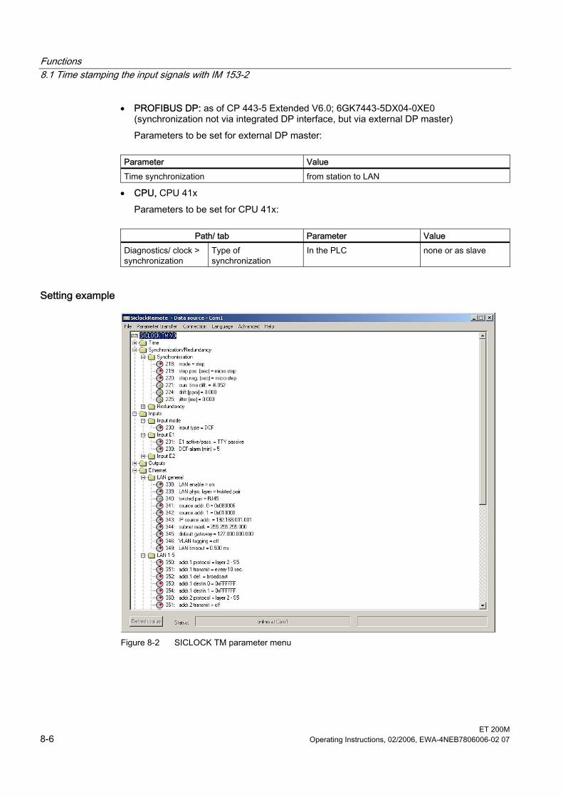
Functions 8.1 Time stamping the input signals with IM 153-2
ET 200M 8-6 Operating Instructions, 02/2006, EWA-4NEB7806006-02 07
• PROFIBUS DP: as of CP 443-5 Extended V6.0; 6GK7443-5DX04-0XE0 (synchronization not via integrated DP interface, but via external DP master) Parameters to be set for external DP master:
Parameter Value Time synchronization from station to LAN
• CPU, CPU 41x Parameters to be set for CPU 41x:
Path/ tab Parameter Value
Diagnostics/ clock > synchronization
Type of synchronization
In the PLC none or as slave
Setting example
Figure 8-2 SICLOCK TM parameter menu
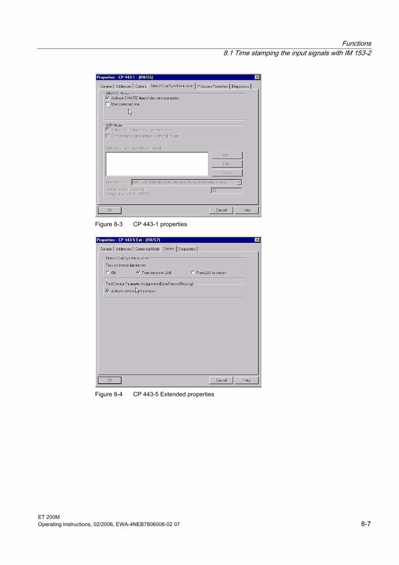
Functions 8.1 Time stamping the input signals with IM 153-2
ET 200M Operating Instructions, 02/2006, EWA-4NEB7806006-02 07 8-7
Figure 8-3 CP 443-1 properties
Figure 8-4 CP 443-5 Extended properties
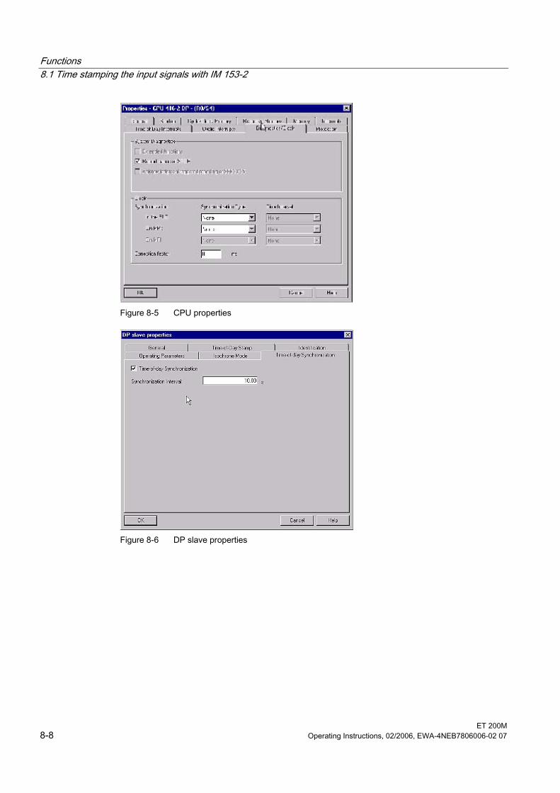
Functions 8.1 Time stamping the input signals with IM 153-2
ET 200M 8-8 Operating Instructions, 02/2006, EWA-4NEB7806006-02 07
Figure 8-5 CPU properties
Figure 8-6 DP slave properties
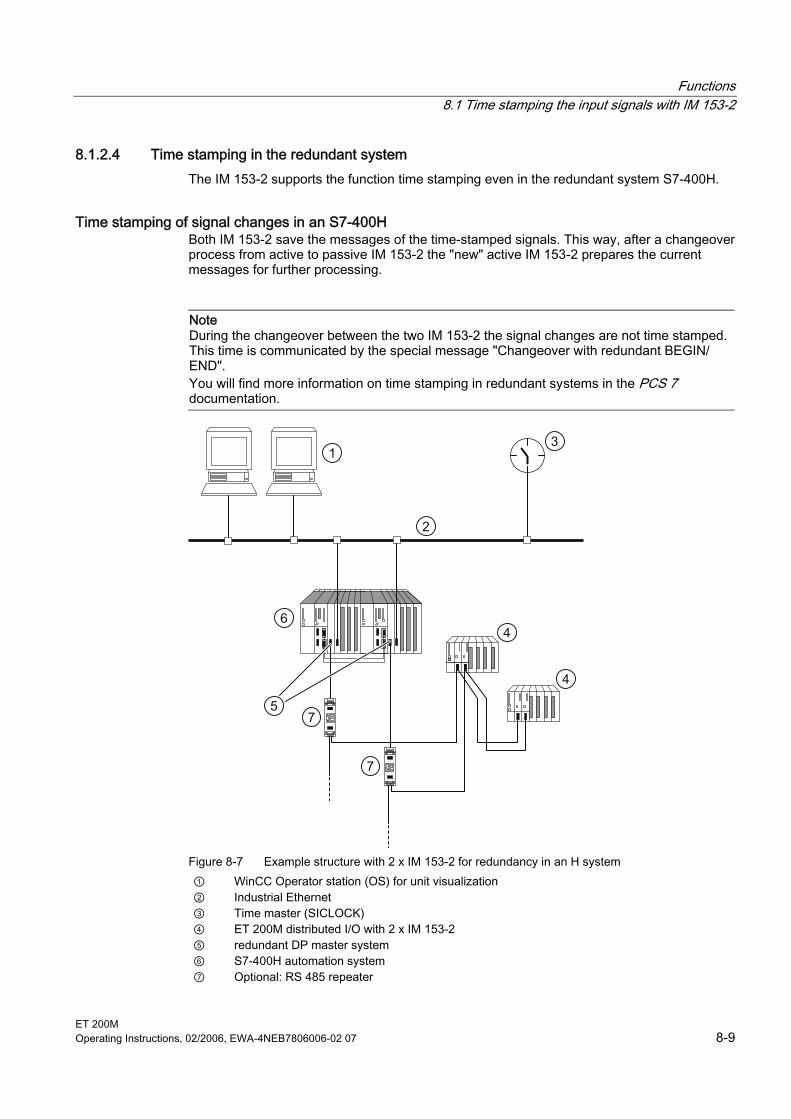
Functions 8.1 Time stamping the input signals with IM 153-2
ET 200M Operating Instructions, 02/2006, EWA-4NEB7806006-02 07 8-9
8.1.2.4 Time stamping in the redundant system The IM 153-2 supports the function time stamping even in the redundant system S7-400H.
Time stamping of signal changes in an S7-400H Both IM 153-2 save the messages of the time-stamped signals. This way, after a changeover process from active to passive IM 153-2 the "new" active IM 153-2 prepares the current messages for further processing.
Note During the changeover between the two IM 153-2 the signal changes are not time stamped. This time is communicated by the special message "Changeover with redundant BEGIN/ END". You will find more information on time stamping in redundant systems in the PCS 7 documentation.
7
7
1
2
3
4
4
5
6
Figure 8-7 Example structure with 2 x IM 153-2 for redundancy in an H system ① WinCC Operator station (OS) for unit visualization ② Industrial Ethernet ③ Time master (SICLOCK) ④ ET 200M distributed I/O with 2 x IM 153-2 ⑤ redundant DP master system ⑥ S7-400H automation system ⑦ Optional: RS 485 repeater
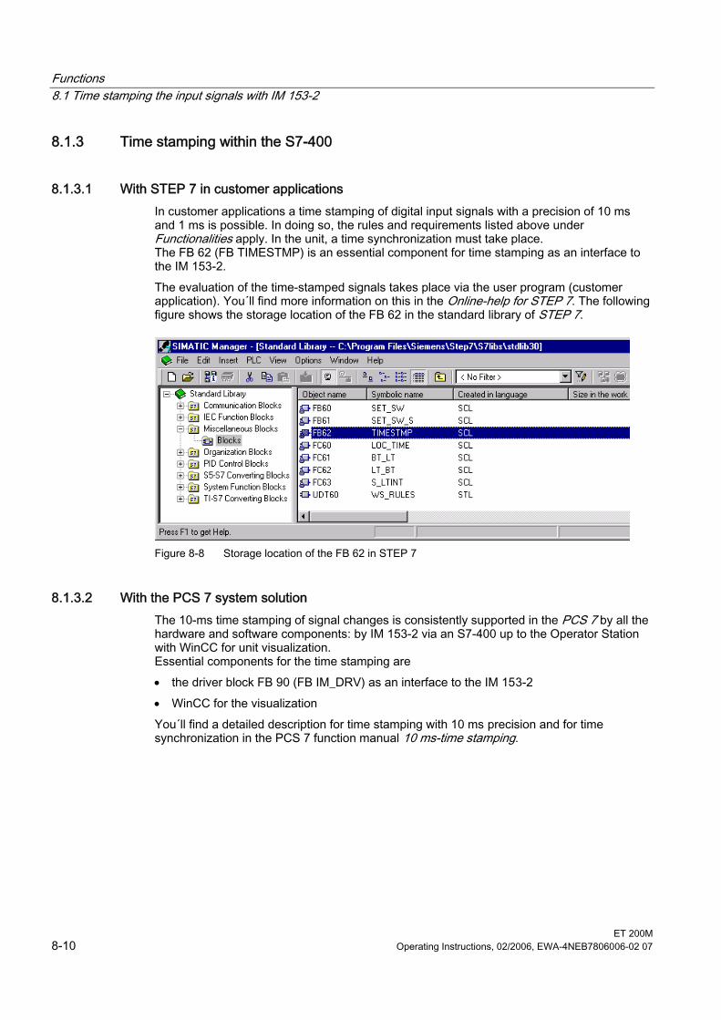
Functions 8.1 Time stamping the input signals with IM 153-2
ET 200M 8-10 Operating Instructions, 02/2006, EWA-4NEB7806006-02 07
8.1.3 Time stamping within the S7-400
8.1.3.1 With STEP 7 in customer applications In customer applications a time stamping of digital input signals with a precision of 10 ms and 1 ms is possible. In doing so, the rules and requirements listed above under Functionalities apply. In the unit, a time synchronization must take place. The FB 62 (FB TIMESTMP) is an essential component for time stamping as an interface to the IM 153-2. The evaluation of the time-stamped signals takes place via the user program (customer application). You´ll find more information on this in the Online-help for STEP 7. The following figure shows the storage location of the FB 62 in the standard library of STEP 7.
Figure 8-8 Storage location of the FB 62 in STEP 7
8.1.3.2 With the PCS 7 system solution The 10-ms time stamping of signal changes is consistently supported in the PCS 7 by all the hardware and software components: by IM 153-2 via an S7-400 up to the Operator Station with WinCC for unit visualization. Essential components for the time stamping are • the driver block FB 90 (FB IM_DRV) as an interface to the IM 153-2 • WinCC for the visualization You´ll find a detailed description for time stamping with 10 ms precision and for time synchronization in the PCS 7 function manual 10 ms-time stamping.
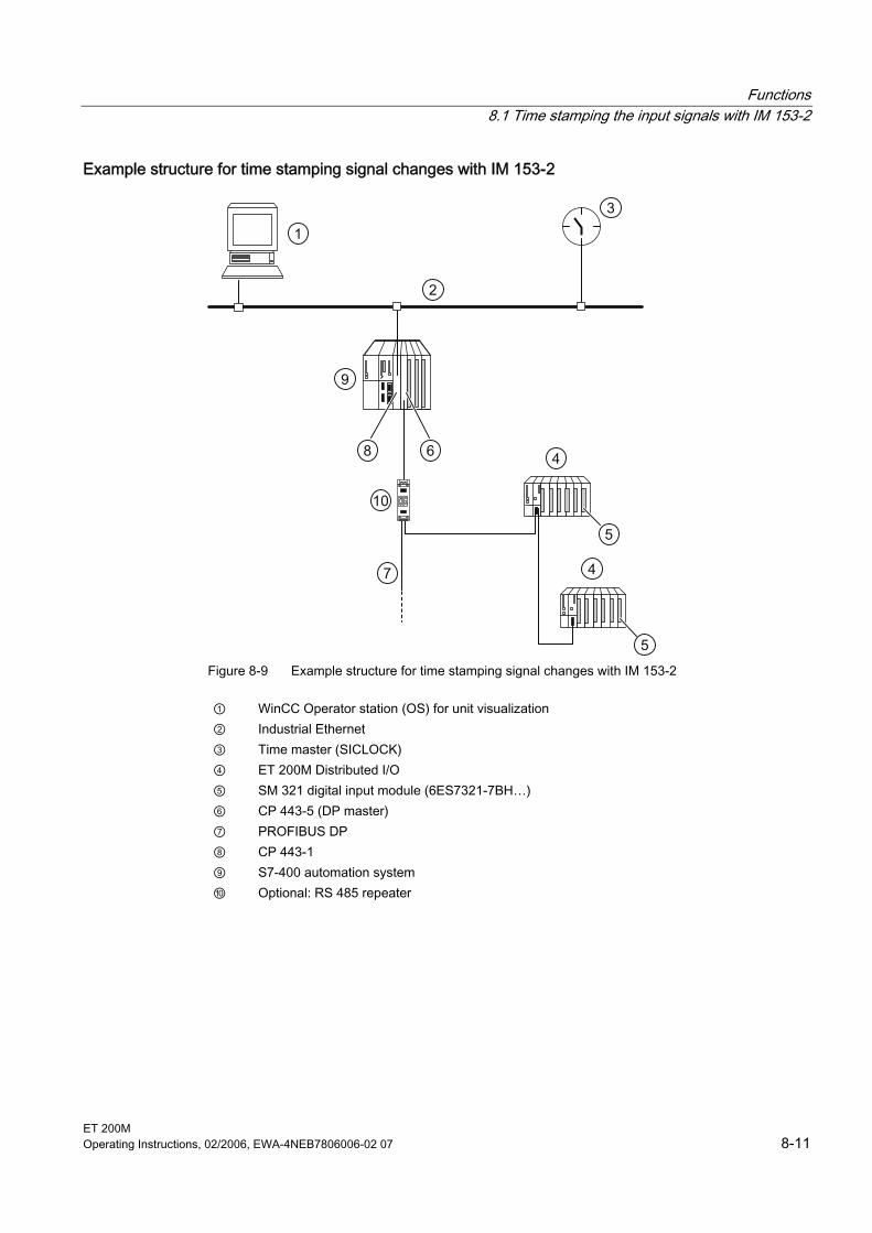
Functions 8.1 Time stamping the input signals with IM 153-2
ET 200M Operating Instructions, 02/2006, EWA-4NEB7806006-02 07 8-11
Example structure for time stamping signal changes with IM 153-2
10
1
2
3
4
5
4
5
6
7
8
9
Figure 8-9 Example structure for time stamping signal changes with IM 153-2
① WinCC Operator station (OS) for unit visualization ② Industrial Ethernet ③ Time master (SICLOCK) ④ ET 200M Distributed I/O ⑤ SM 321 digital input module (6ES7321-7BH…) ⑥ CP 443-5 (DP master) ⑦ PROFIBUS DP ⑧ CP 443-1 ⑨ S7-400 automation system ⑩ Optional: RS 485 repeater
Functions 8.1 Time stamping the input signals with IM 153-2
ET 200M 8-12 Operating Instructions, 02/2006, EWA-4NEB7806006-02 07
8.1.4 Time stamping outside of S7-400
8.1.4.1 Prerequisites With the interface module IM 153-2Bxx1, time stamping is also possible outside of an S7-400 automation system. The above principles and rules apply - if complied with, precisions of up to 1 ms can be achieved. Synchronization interval for the time: 10 s
Demands on the ET 200M and DP master ET 200M: • IM 153-2 as of order number 6ES7153-2Bxx1-0XB0 • suitable DI modules • IM 153-2 must be configured via GSD rev. 5 (e.g. enabling of interrupts) • for IM 153-2 the DPV1 mode must be activated • Synchronization interval in accordance with the setting on the clock master DP master: • must fulfill requirements in accordance with DPV1 • must be able to process interrupts • must be able to process data records (read/ write) • must be able to send/ forward time message frames or a clock master must be available
in the same PROFIBUS DP line
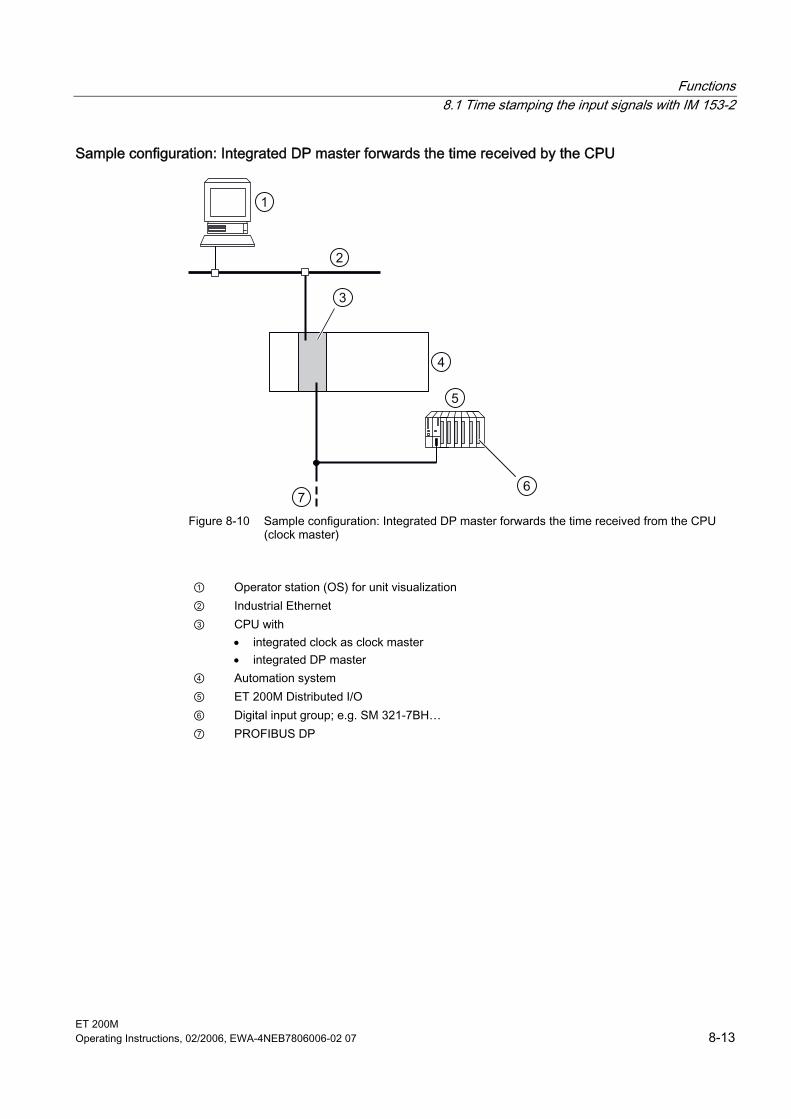
Functions 8.1 Time stamping the input signals with IM 153-2
ET 200M Operating Instructions, 02/2006, EWA-4NEB7806006-02 07 8-13
Sample configuration: Integrated DP master forwards the time received by the CPU
1
2
3
4
5
67
Figure 8-10 Sample configuration: Integrated DP master forwards the time received from the CPU (clock master)
① Operator station (OS) for unit visualization ② Industrial Ethernet ③ CPU with
• integrated clock as clock master • integrated DP master
④ Automation system ⑤ ET 200M Distributed I/O ⑥ Digital input group; e.g. SM 321-7BH… ⑦ PROFIBUS DP
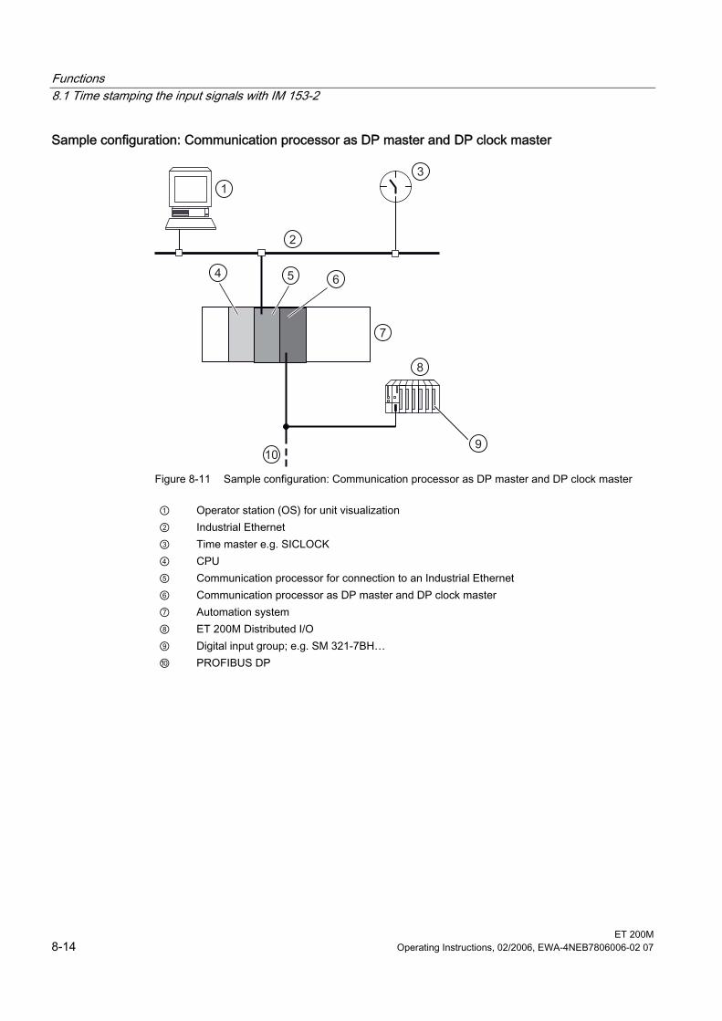
Functions 8.1 Time stamping the input signals with IM 153-2
ET 200M 8-14 Operating Instructions, 02/2006, EWA-4NEB7806006-02 07
Sample configuration: Communication processor as DP master and DP clock master
1
2
4
3
5 6
7
8
910
Figure 8-11 Sample configuration: Communication processor as DP master and DP clock master
① Operator station (OS) for unit visualization ② Industrial Ethernet ③ Time master e.g. SICLOCK ④ CPU ⑤ Communication processor for connection to an Industrial Ethernet ⑥ Communication processor as DP master and DP clock master ⑦ Automation system ⑧ ET 200M Distributed I/O ⑨ Digital input group; e.g. SM 321-7BH… ⑩ PROFIBUS DP
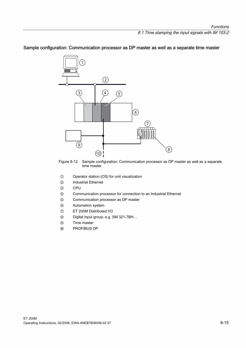
Functions 8.1 Time stamping the input signals with IM 153-2
ET 200M Operating Instructions, 02/2006, EWA-4NEB7806006-02 07 8-15
Sample configuration: Communication processor as DP master as well as a separate time master
1
2
43 5
6
7
89
10 Figure 8-12 Sample configuration: Communication processor as DP master as well as a separate
time master
① Operator station (OS) for unit visualization ② Industrial Ethernet ③ CPU ④ Communication processor for connection to an Industrial Ethernet ⑤ Communication processor as DP master ⑥ Automation system ⑦ ET 200M Distributed I/O ⑧ Digital input group; e.g. SM 321-7BH… ⑨ Time master ⑩ PROFIBUS DP

Functions 8.1 Time stamping the input signals with IM 153-2
ET 200M 8-16 Operating Instructions, 02/2006, EWA-4NEB7806006-02 07
8.1.4.2 Operating principle • The 240 data record is the configured data record for the time stamping on the ET 200M.
It defines which modules and which input channels of which type can be called upon by the IM 153-2 for the time stamping. When accepting the data record 240 the consistency of the data record with the configured structure of the slave is checked. As soon as this data record 240 is transmitted correctly to the IM 153-2 the time stamping is activated.
• If the input signal on one of the monitored inputs changes, this event is time stamped by the IM 153-2 and stored in one of hte data records 100 to 114.
• Then the IM 153-2 triggers a process interrupt. • The master reacts with a diagnosis requirement to the slave. • The IM 153-2 responds to this with a diagnostic frame. This diagnostic frame includes,
among other things, the number of the data record that includes the time-stamped messages.
• Because of this diagnostic frame the associated run level "process interrupt" is launched in the user program. Within this run level, the user must be able to tell which data record is to be read with messages from the IM 153-2. Depending on the application case, the user must also ensure multiple calls on this run level. In your CPU´s manual, look up DPV1-blocks, e.g. "RALRM".
• The user program monitors entries in the run level "process interrupt". As soon as an entry is detected, the data record is read from the IM 153-2. A block in accordance with DPV1 also serves to do this. Refer to DPV1-blocks, e.g. "RDREC" in your CPU´s manual.
• In accordance with the requirements of your application, the data record is saved or further processed. Every single signal message comprises 12 bytes, a data record can include up to 20 messages.
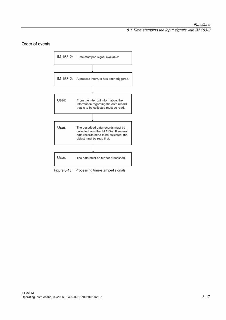
Functions 8.1 Time stamping the input signals with IM 153-2
ET 200M Operating Instructions, 02/2006, EWA-4NEB7806006-02 07 8-17
Order of events
Figure 8-13 Processing time-stamped signals
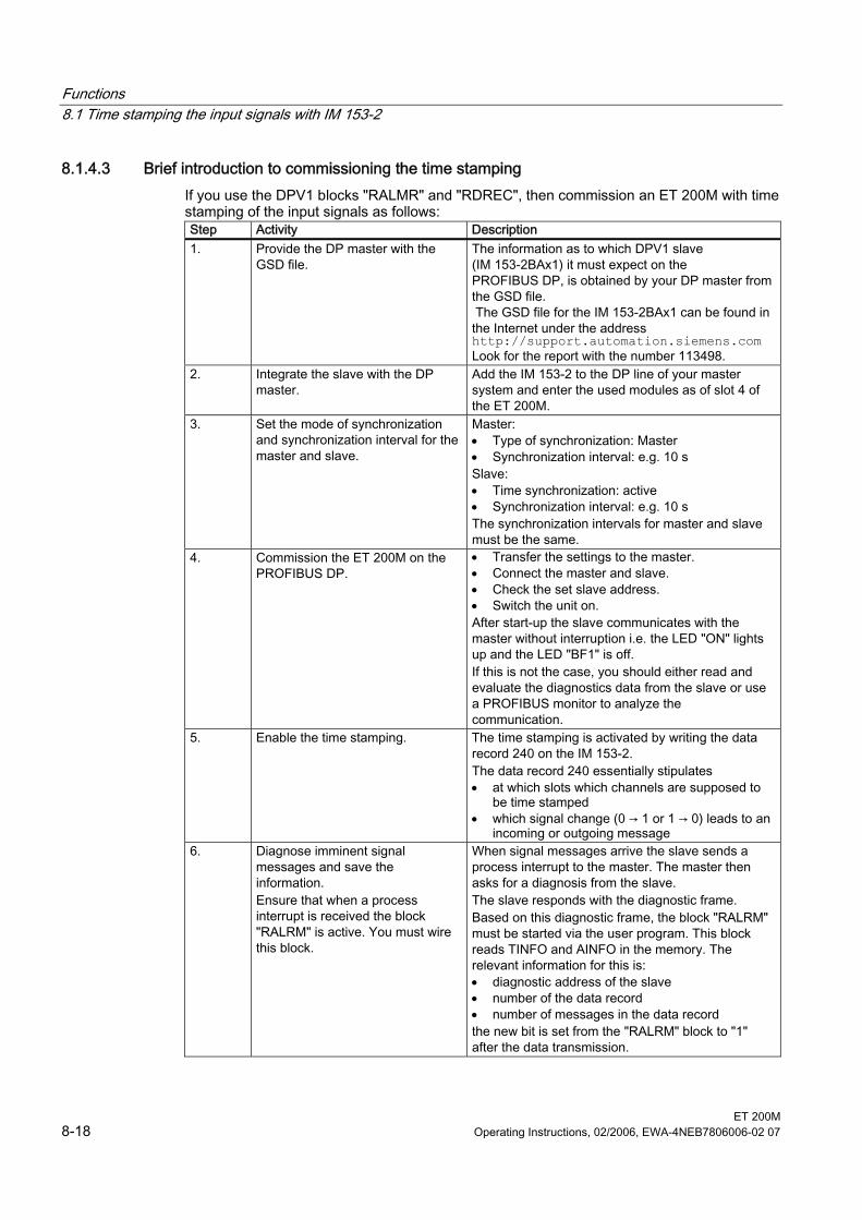
Functions 8.1 Time stamping the input signals with IM 153-2
ET 200M 8-18 Operating Instructions, 02/2006, EWA-4NEB7806006-02 07
8.1.4.3 Brief introduction to commissioning the time stamping If you use the DPV1 blocks "RALMR" and "RDREC", then commission an ET 200M with time stamping of the input signals as follows: Step Activity Description 1. Provide the DP master with the
GSD file. The information as to which DPV1 slave (IM 153-2BAx1) it must expect on the PROFIBUS DP, is obtained by your DP master from the GSD file. The GSD file for the IM 153-2BAx1 can be found in the Internet under the address http://support.automation.siemens.com Look for the report with the number 113498.
2. Integrate the slave with the DP master.
Add the IM 153-2 to the DP line of your master system and enter the used modules as of slot 4 of the ET 200M.
3. Set the mode of synchronization and synchronization interval for the master and slave.
Master: • Type of synchronization: Master • Synchronization interval: e.g. 10 s Slave: • Time synchronization: active • Synchronization interval: e.g. 10 s The synchronization intervals for master and slave must be the same.
4. Commission the ET 200M on the PROFIBUS DP.
• Transfer the settings to the master. • Connect the master and slave. • Check the set slave address. • Switch the unit on. After start-up the slave communicates with the master without interruption i.e. the LED "ON" lights up and the LED "BF1" is off. If this is not the case, you should either read and evaluate the diagnostics data from the slave or use a PROFIBUS monitor to analyze the communication.
5. Enable the time stamping. The time stamping is activated by writing the data record 240 on the IM 153-2. The data record 240 essentially stipulates • at which slots which channels are supposed to
be time stamped • which signal change (0 → 1 or 1 → 0) leads to an
incoming or outgoing message 6. Diagnose imminent signal
messages and save the information. Ensure that when a process interrupt is received the block "RALRM" is active. You must wire this block.
When signal messages arrive the slave sends a process interrupt to the master. The master then asks for a diagnosis from the slave. The slave responds with the diagnostic frame. Based on this diagnostic frame, the block "RALRM" must be started via the user program. This block reads TINFO and AINFO in the memory. The relevant information for this is: • diagnostic address of the slave • number of the data record • number of messages in the data record the new bit is set from the "RALRM" block to "1" after the data transmission.
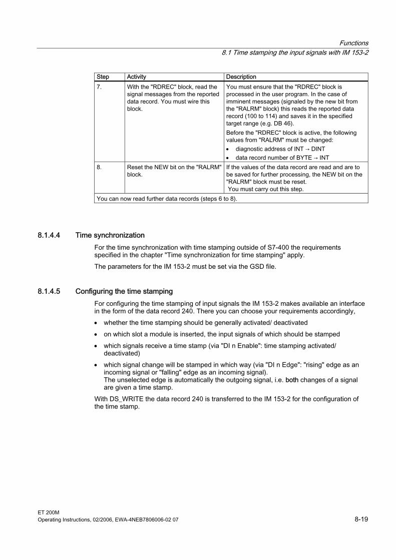
Functions 8.1 Time stamping the input signals with IM 153-2
ET 200M Operating Instructions, 02/2006, EWA-4NEB7806006-02 07 8-19
Step Activity Description 7. With the "RDREC" block, read the
signal messages from the reported data record. You must wire this block.
You must ensure that the "RDREC" block is processed in the user program. In the case of imminent messages (signaled by the new bit from the "RALRM" block) this reads the reported data record (100 to 114) and saves it in the specified target range (e.g. DB 46). Before the "RDREC" block is active, the following values from "RALRM" must be changed: • diagnostic address of INT → DINT • data record number of BYTE → INT
8. Reset the NEW bit on the "RALRM" block.
If the values of the data record are read and are to be saved for further processing, the NEW bit on the "RALRM" block must be reset. You must carry out this step.
You can now read further data records (steps 6 to 8).
8.1.4.4 Time synchronization For the time synchronization with time stamping outside of S7-400 the requirements specified in the chapter "Time synchronization for time stamping" apply. The parameters for the IM 153-2 must be set via the GSD file.
8.1.4.5 Configuring the time stamping For configuring the time stamping of input signals the IM 153-2 makes available an interface in the form of the data record 240. There you can choose your requirements accordingly, • whether the time stamping should be generally activated/ deactivated • on which slot a module is inserted, the input signals of which should be stamped • which signals receive a time stamp (via "DI n Enable": time stamping activated/
deactivated) • which signal change will be stamped in which way (via "DI n Edge": "rising" edge as an
incoming signal or "falling" edge as an incoming signal). The unselected edge is automatically the outgoing signal, i.e. both changes of a signal are given a time stamp.
With DS_WRITE the data record 240 is transferred to the IM 153-2 for the configuration of the time stamp.
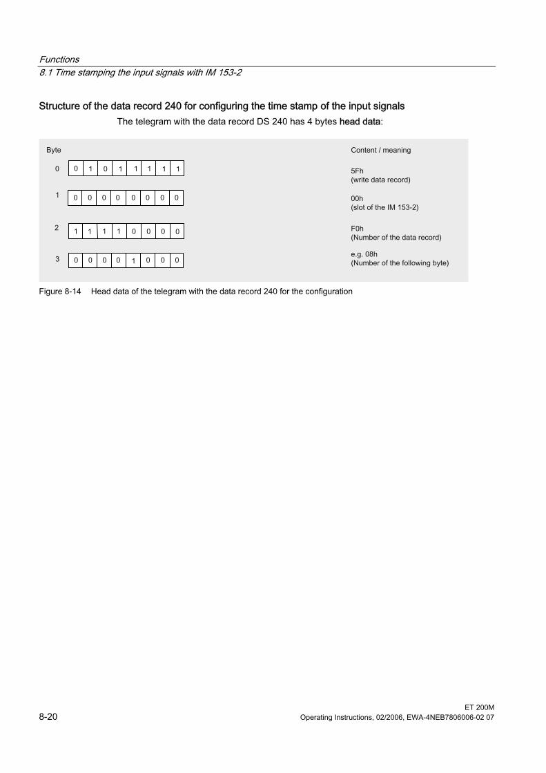
Functions 8.1 Time stamping the input signals with IM 153-2
ET 200M 8-20 Operating Instructions, 02/2006, EWA-4NEB7806006-02 07
Structure of the data record 240 for configuring the time stamp of the input signals The telegram with the data record DS 240 has 4 bytes head data:
Figure 8-14 Head data of the telegram with the data record 240 for the configuration
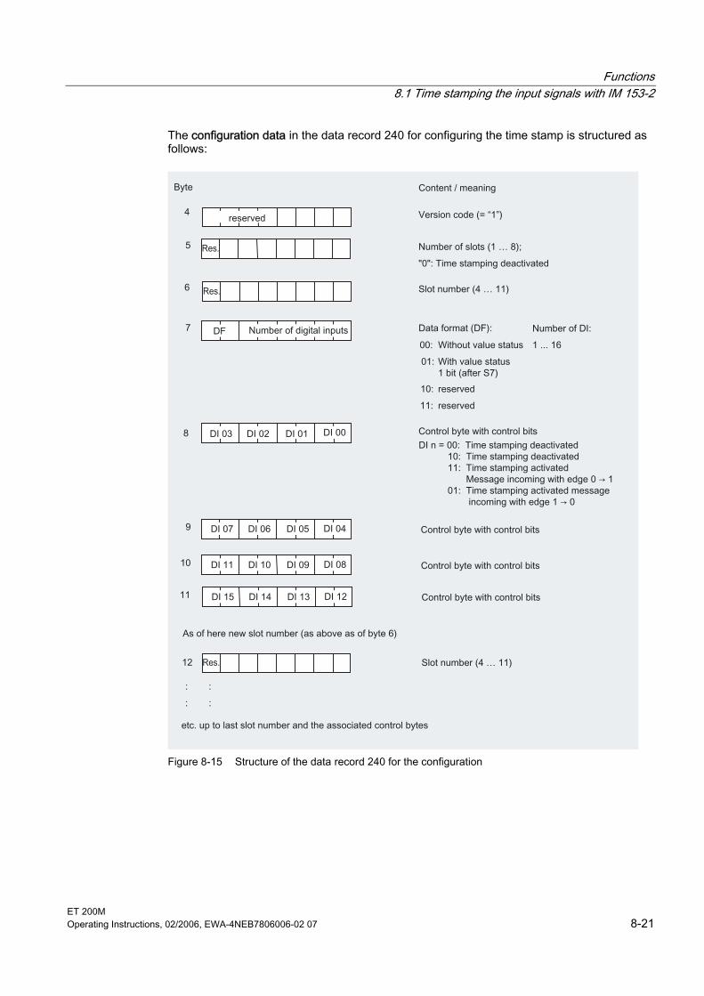
Functions 8.1 Time stamping the input signals with IM 153-2
ET 200M Operating Instructions, 02/2006, EWA-4NEB7806006-02 07 8-21
The configuration data in the data record 240 for configuring the time stamp is structured as follows:
Figure 8-15 Structure of the data record 240 for the configuration
Functions 8.1 Time stamping the input signals with IM 153-2
ET 200M 8-22 Operating Instructions, 02/2006, EWA-4NEB7806006-02 07
Parameterizing the edges • Time stamp with edge 0 → 1:
With a signal change on the digital input of 0 → 1 a signal message with signal status 80h (incoming) is stored in the data record (DS 100 to 114).
• Time stamp with edge 1 → 0: With a signal change on the digital input of 1 → 0 a signal message with signal status 80h (incoming) is stored in the data record (DS 100 to 114).
Example For a fully connected ET 200M (8 digital inputs with in each case 16 digital inputs) the data record 240 has a total of 50 bytes for the configuration of the time stamp.
Return values on DS_WRITE Possible return values on writing a data record can be obtained in accordance with the DPV1 standard.
8.1.4.6 Structure of the process interrupt
Structure of the alarm information The process interrupt is structured in accordance with the DPV1 standard.
Table 8-1 Contents of the diagnostic frame (example)
Value Meaning 00 0C 00h Station status 05h Master address (e.g. B 5) 80 1Eh Manufacturer ID 43 00 00h Module diagnostics (variable length, here 3 bytes) 07 82 00 00 00 00 00h Module status (variable length, here 7 bytes) 08 02 02 20 00 67 01 0Dh Interrupt part with time stamping
Table 8-2 Contents of the interrupt section (example)
Value Meaning 08h • Bit 7 … 6: Code for the interrupt
• Bit 5 … 0: Length of interrupt section 02h Interrupt type 02h Slot 20h • Bit 7 … 3: Interrupt sequence number
• Bit 2 … 0: Types of interrupt 00h Status of time stamping 67h Data record number of the data record to be fetched
(64h to 72h = DS 100 … 114) 01h Number of messages in the data record
(01h to 14h = 1 … 20) 0Dh fixed value
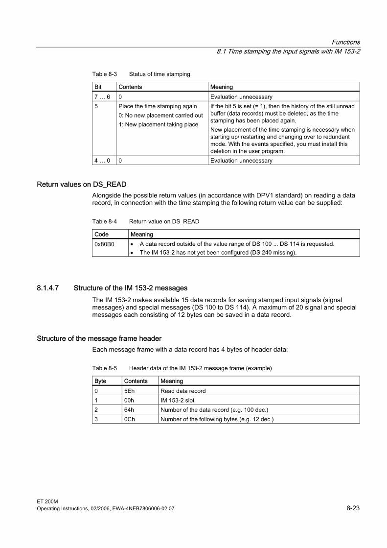
Functions 8.1 Time stamping the input signals with IM 153-2
ET 200M Operating Instructions, 02/2006, EWA-4NEB7806006-02 07 8-23
Table 8-3 Status of time stamping
Bit Contents Meaning 7 … 6 0 Evaluation unnecessary 5 Place the time stamping again
0: No new placement carried out 1: New placement taking place
If the bit 5 is set (= 1), then the history of the still unread buffer (data records) must be deleted, as the time stamping has been placed again. New placement of the time stamping is necessary when starting up/ restarting and changing over to redundant mode. With the events specified, you must install this deletion in the user program.
4 … 0 0 Evaluation unnecessary
Return values on DS_READ Alongside the possible return values (in accordance with DPV1 standard) on reading a data record, in connection with the time stamping the following return value can be supplied:
Table 8-4 Return value on DS_READ
Code Meaning 0x80B0 • A data record outside of the value range of DS 100 ... DS 114 is requested.
• The IM 153-2 has not yet been configured (DS 240 missing).
8.1.4.7 Structure of the IM 153-2 messages The IM 153-2 makes available 15 data records for saving stamped input signals (signal messages) and special messages (DS 100 to DS 114). A maximum of 20 signal and special messages each consisting of 12 bytes can be saved in a data record.
Structure of the message frame header Each message frame with a data record has 4 bytes of header data:
Table 8-5 Header data of the IM 153-2 message frame (example)
Byte Contents Meaning 0 5Eh Read data record 1 00h IM 153-2 slot 2 64h Number of the data record (e.g. 100 dec.) 3 0Ch Number of the following bytes (e.g. 12 dec.)
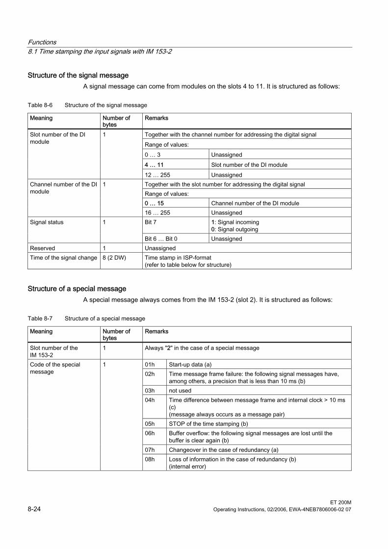
Functions 8.1 Time stamping the input signals with IM 153-2
ET 200M 8-24 Operating Instructions, 02/2006, EWA-4NEB7806006-02 07
Structure of the signal message A signal message can come from modules on the slots 4 to 11. It is structured as follows:
Table 8-6 Structure of the signal message
Meaning Number of bytes
Remarks
Together with the channel number for addressing the digital signal Range of values: 0 … 3 Unassigned 4 … 11 Slot number of the DI module
Slot number of the DI module
1
12 … 255 Unassigned Together with the slot number for addressing the digital signal Range of values: 0 … 15 Channel number of the DI module
Channel number of the DI module
1
16 … 255 Unassigned Bit 7 1: Signal incoming
0: Signal outgoing Signal status 1
Bit 6 … Bit 0 Unassigned Reserved 1 Unassigned Time of the signal change 8 (2 DW) Time stamp in ISP-format
(refer to table below for structure)
Structure of a special message A special message always comes from the IM 153-2 (slot 2). It is structured as follows:
Table 8-7 Structure of a special message
Meaning Number of bytes
Remarks
Slot number of the IM 153-2
1 Always "2" in the case of a special message
01h Start-up data (a) 02h Time message frame failure: the following signal messages have,
among others, a precision that is less than 10 ms (b) 03h not used 04h Time difference between message frame and internal clock > 10 ms
(c) (message always occurs as a message pair)
05h STOP of the time stamping (b) 06h Buffer overflow: the following signal messages are lost until the
buffer is clear again (b) 07h Changeover in the case of redundancy (a)
Code of the special message
1
08h Loss of information in the case of redundancy (b) (internal error)
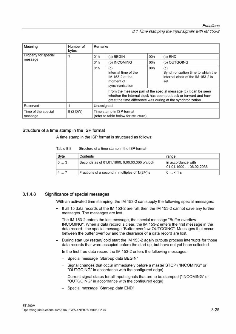
Functions 8.1 Time stamping the input signals with IM 153-2
ET 200M Operating Instructions, 02/2006, EWA-4NEB7806006-02 07 8-25
Meaning Number of bytes
Remarks
01h (a) BEGIN 00h (a) END 01h (b) INCOMING 00h (b) OUTGOING
(c) internal time of the IM 153-2 at the moment of synchronization
00h (c) Synchronization time to which the internal clock of the IM 153-2 is set
Property for special message
1
01h
From the message pair of the special message (c) it can be seen whether the internal clock has been put back or forward and how great the time difference was during at the synchronization.
Reserved 1 Unassigned Time of the special message
8 (2 DW) Time stamp in ISP-format (refer to table below for structure)
Structure of a time stamp in the ISP format A time stamp in the ISP format is structured as follows:
Table 8-8 Structure of a time stamp in the ISP format
Byte Contents range 0 … 3 Seconds as of 01.01.1900; 0:00:00,000 o´clock in accordance with
01.01.1900 … 06.02.2036 4 … 7 Fractions of a second in multiples of 1/(232) s 0 … < 1 s
8.1.4.8 Significance of special messages With an activated time stamping, the IM 153-2 can supply the following special messages: • If all 15 data records of the IM 153-2 are full, then the IM 153-2 cannot save any further
messages. The messages are lost. The IM 153-2 enters the last message, the special message "Buffer overflow INCOMING". When a data record is clear, the IM 153-2 enters the first message in the data record - the special message "Buffer overflow OUTGOING". Messages that occur between the buffer overflow and the clearance of a data record are lost.
• During start up/ restart/ cold start the IM 153-2 again outputs process interrupts for those data records that were occupied before the start up, but have not yet been collected. In the first free data record the IM 153-2 enters the following messages: – Special message "Start-up data BEGIN" – Signal changes that occur immediately before a master STOP ("INCOMING" or
"OUTGOING" in accordance with the configured edge) – Current signal status for all input signals that are to be stamped ("INCOMING" or
"OUTGOING" in accordance with the configured edge) – Special message "Start-up data END"

Functions 8.1 Time stamping the input signals with IM 153-2
ET 200M 8-26 Operating Instructions, 02/2006, EWA-4NEB7806006-02 07
With redundant mode In redundant mode it also applies that: • during a changeover between active and passive IM 153-2 the time stamping is
interrupted. With the special message "Changeover with redundant BEGIN/END" the period of interruption is displayed.
• If the communication between the two IM 153-2 is interrupted in redundant mode, the special message "Loss of information in the case of redundancy INCOMING" is output. As soon as the communication between the active and passive IM 153-2s is possible again, the special message "Loss of information in the case of redundancy OUTGOING" is output. It is not possible to adjust this afterwards, as changing over to the error state of the interface module IM 153-2 could lead to message loss.
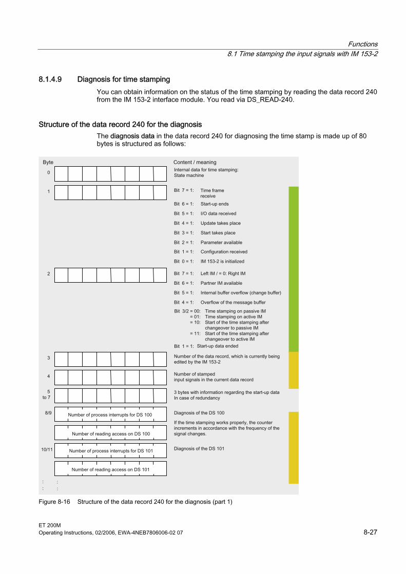
Functions 8.1 Time stamping the input signals with IM 153-2
ET 200M Operating Instructions, 02/2006, EWA-4NEB7806006-02 07 8-27
8.1.4.9 Diagnosis for time stamping You can obtain information on the status of the time stamping by reading the data record 240 from the IM 153-2 interface module. You read via DS_READ-240.
Structure of the data record 240 for the diagnosis The diagnosis data in the data record 240 for diagnosing the time stamp is made up of 80 bytes is structured as follows:
Figure 8-16 Structure of the data record 240 for the diagnosis (part 1)
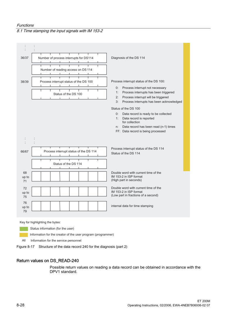
Functions 8.1 Time stamping the input signals with IM 153-2
ET 200M 8-28 Operating Instructions, 02/2006, EWA-4NEB7806006-02 07
Figure 8-17 Structure of the data record 240 for the diagnosis (part 2)
Return values on DS_READ-240 Possible return values on reading a data record can be obtained in accordance with the DPV1 standard.
Functions 8.2 Clock synchronization on the I/O bus
ET 200M Operating Instructions, 02/2006, EWA-4NEB7806006-02 07 8-29
8.2 8.2 Clock synchronization on the I/O bus
Properties The interface module IM 153-2 as of 6ES7153-2Bxx1-0XB0 supports the time synchronization on the I/O bus. • The IM 153-2 sends the current time to the I/O bus after its time synchronization has
been cleared with the configuration. • The synchronization on the I/O bus takes place in the synchronization interval that has
been set on the PROFIBUS DP. • In view of the time received on the PROFIBUS DP, the precision deteriorates only
slightly. The precision of 10 ms is always guaranteed.
Operating steps for activation The activation of the time synchronization on the I/O bus can be carried out as follows: PROFIBUS DP: 1. Complete the PROFIBUS DP with a time master. 2. Activate the time synchronization in the properties of the DP master.
Note In the H system you must insert a time master in both the PROFIBUS DP systems and activate the time synchronization.
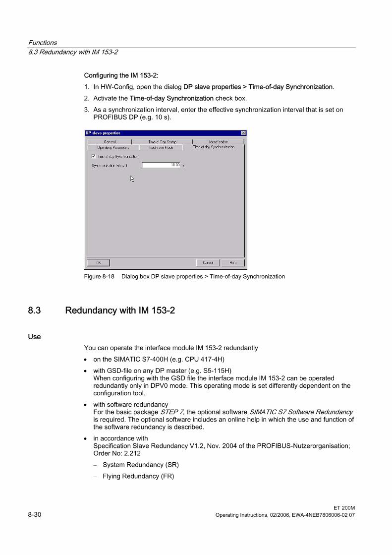
Functions 8.3 Redundancy with IM 153-2
ET 200M 8-30 Operating Instructions, 02/2006, EWA-4NEB7806006-02 07
Configuring the IM 153-2: 1. In HW-Config, open the dialog DP slave properties > Time-of-day Synchronization. 2. Activate the Time-of-day Synchronization check box. 3. As a synchronization interval, enter the effective synchronization interval that is set on
PROFIBUS DP (e.g. 10 s).
Figure 8-18 Dialog box DP slave properties > Time-of-day Synchronization
8.3 8.3 Redundancy with IM 153-2
Use You can operate the interface module IM 153-2 redundantly • on the SIMATIC S7-400H (e.g. CPU 417-4H) • with GSD-file on any DP master (e.g. S5-115H)
When configuring with the GSD file the interface module IM 153-2 can be operated redundantly only in DPV0 mode. This operating mode is set differently dependent on the configuration tool.
• with software redundancy For the basic package STEP 7, the optional software SIMATIC S7 Software Redundancy is required. The optional software includes an online help in which the use and function of the software redundancy is described.
• in accordance with Specification Slave Redundancy V1.2, Nov. 2004 of the PROFIBUS-Nutzerorganisation; Order No: 2.212 – System Redundancy (SR) – Flying Redundancy (FR)
Functions 8.3 Redundancy with IM 153-2
ET 200M Operating Instructions, 02/2006, EWA-4NEB7806006-02 07 8-31
Conditions for the ET 200M • Configuration with active bus modules
The configuration with active bus modules 6ES7195-7HD10-0XA0 or 6ES7195-7HD80-0XA0 ensures a greater availability of the ET 200M.
• 2 x IM 153-2 on bus module BM IM/IM The location rules specified in chapter Installing > Configuring the mechanical structure apply to the active bus modules and interface modules.
• Software redundancy and system redundancy (SR) are possible with the IM 153-2/-2 FO as of 6ES7153-2AA02-0XB0/-2AB01-0XB0
• Flying redundancy (FR) is possible with IM 153-2/-2 FO as of 6ES7153-2Bxx1-0XB0 – The redundant master system must be configured in accordance with the demands on
H systems. – The GSD file of the IM 153-2 (GSD rev. 5) must be imported to the configuration tool.
Note STEP 7 offers no support for configuring an H system with flying redundancy.
• In redundant mode the function SYNC/ FREEZE is not activated.
Note If the function SYNC/ FREEZE is nevertheless activated in a redundant system, the user bears the responsibility for the behavior of the H system (e.g. when changing over).
• In a redundant system, you can only use the IM 153-2 interface module on DP masters that support the "fail safe" parameter. The IM 153-2 will not run on DP masters that do not support this parameter, and the BF LED flashes. Tip: You can see in the GSD-file of the DP master whether this "fail safe" is supported.
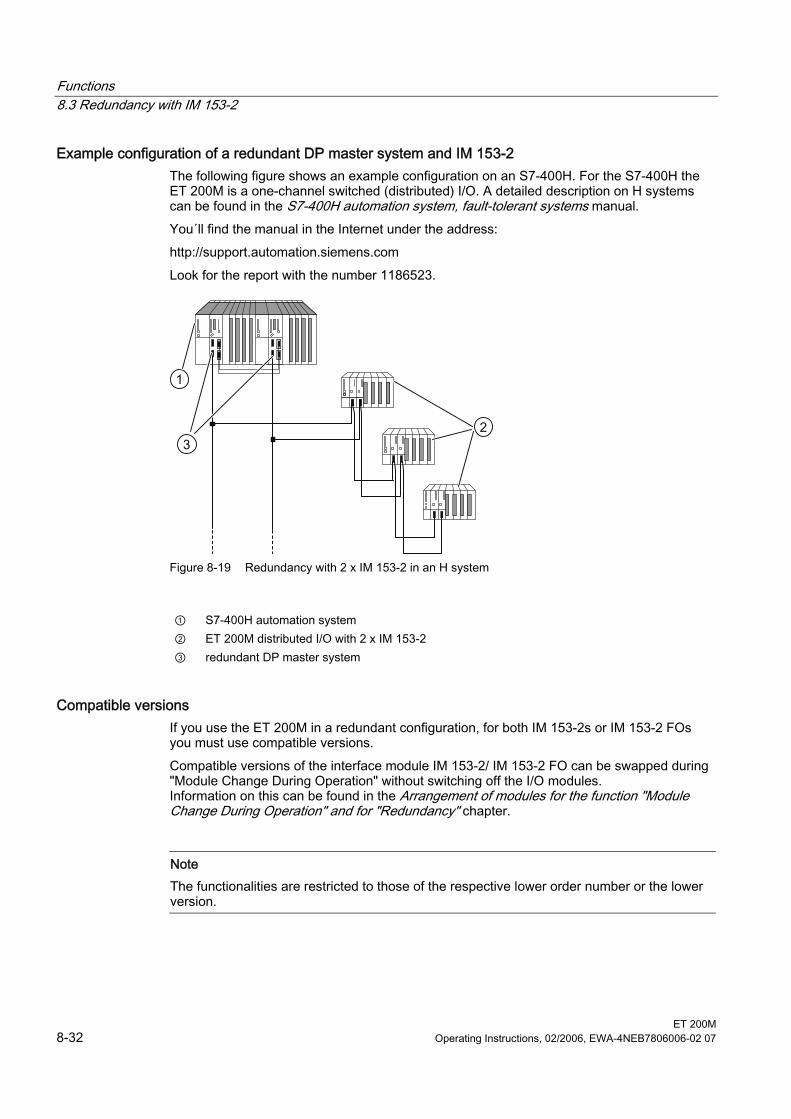
Functions 8.3 Redundancy with IM 153-2
ET 200M 8-32 Operating Instructions, 02/2006, EWA-4NEB7806006-02 07
Example configuration of a redundant DP master system and IM 153-2 The following figure shows an example configuration on an S7-400H. For the S7-400H the ET 200M is a one-channel switched (distributed) I/O. A detailed description on H systems can be found in the S7-400H automation system, fault-tolerant systems manual. You´ll find the manual in the Internet under the address: http://support.automation.siemens.com Look for the report with the number 1186523.
1
23
Figure 8-19 Redundancy with 2 x IM 153-2 in an H system
① S7-400H automation system ② ET 200M distributed I/O with 2 x IM 153-2 ③ redundant DP master system
Compatible versions If you use the ET 200M in a redundant configuration, for both IM 153-2s or IM 153-2 FOs you must use compatible versions. Compatible versions of the interface module IM 153-2/ IM 153-2 FO can be swapped during "Module Change During Operation" without switching off the I/O modules. Information on this can be found in the Arrangement of modules for the function "Module Change During Operation" and for "Redundancy" chapter.
Note The functionalities are restricted to those of the respective lower order number or the lower version.
Functions 8.4 System modification during operation
ET 200M Operating Instructions, 02/2006, EWA-4NEB7806006-02 07 8-33
S7-400H as DP master You require STEP 7 as of V5.0 as well as the software package SIMATIC S7 H-systems for configuring the S7-400H system. DP master 1 and DP master 2: • work off the same user program. • have the same configuration and parameterization for the IM 153-2 interface module.
S5-115H/ -155H as DP master If the IM 153-2 interface module is being used on an S5 H system, the you must configure two DP master systems in the COM PROFIBUS.
Voltage supply for the IM 153-2 interface module In order to ensure availability in redundant mode with 2 x IM 153-2, we recommend that each IM 153-2 is using its own power supply module.
See also Arrangement of the modules for the function "Change During Operation" and/ or "Redundancy" (Page 3-11)
8.4 8.4 System modification during operation
System modifications System modification in RUN is possible with the IM 153-2 in the redundant and in the non-redundant structure: • In the redundant system
– with IM 153-2AA02 as of version 05 – with IM 153-2AB01 as of version 04 – with IM 153-2Bx00 – with IM 153-2Bxx1
• In the non-redundant system – with IM 153-2Bx00 – with IM 153-2Bxx1
Functions 8.4 System modification during operation
ET 200M 8-34 Operating Instructions, 02/2006, EWA-4NEB7806006-02 07
8.4.1 System modification in a non-redundant system A detailed description of this function and its parameterization in non-redundant systems can be found in the function manual System Modification During Operation Using CiR. You´ll find the manual in the Internet under the address http://support.automation.siemens.com Look for the report with the number 14044916.
8.4.2 System modification in a redundant system
Configuring with STEP 7/ PCS 7 Information on using this function in the redundant structure can be found in the S7-400H automation system, fault-tolerance systems manual an din the online help for the H-optional package for STEP 7. You´ll find the manual in the Internet under the address: http://support.automation.siemens.com Look for the report with the number 1186523.
Configuring with a GSD file Basics As of IM 153-2Bx00 it is also possible to modify the system whilst running by configuring with a GSD file. In this case, modules are added to or removed from an ET 200M during operation. Existing modules and modules which are not to be modified are unaffected. During such a reconfiguration, the two IM 153-2 work temporarily with different configuration data. The redundant operating mode for the unaffected modules is, however, retained. Requirements • "Module change in operation" must be enabled during configuration. This must take place
equally for both IM 153-2 of the redundant system. If this is not the case, an IM 153-2 does not start up, i.e. redundant operation is not possible.
Note If "Module Change During Operation" is not cleared, the configuration and parameterization between the two IM 153-2 must be identical.
• The "Start-up at preset configuration ≠ actual configuration" and "Module Change During Operation" parameters must be cleared with both IM 153-2s.
• The slots for modules which are to be added must be available on the active backplane bus. Adding or removing active bus modules is not possible during operation.
Functions 8.4 System modification during operation
ET 200M Operating Instructions, 02/2006, EWA-4NEB7806006-02 07 8-35
Controlling • The configuration of the currently active IM 153-2 applies to the I/O modules of an ET
200M. • If there is a difference in the configuration of the two IM 153-2, the passive IM 153-2
supplies as input data the fixed value "zero" for all inputs. Only when the configuration is equal does the passive IM 153-2 start to deliver the true input data again.
Configuration modification procedure Reconfiguration is performed in the following way (example): 1. Make the appropriate modifications to the configuration offline (remove or add module).
Note The parameters of a module can only be changed by making two configuration modifications in RUN: 1. Remove the module. 2. Add the module with new parameters.
2. Switch one master of the redundant system to passive (all slaves are active at the other master).
3. Load the configuration in the master on the passive line and restart the master → The parameters and configuration data are loaded in the slave.
4. Switch over to the line with the new configuration → The previously loaded configuration now becomes effective. Removed modules are taken out of the data communication and added modules with the new parameters are included in the data communication.
5. The changes are checked by the user. If the changes are OK, the new configuration must also be loaded in the second master. If the changes are not OK, the previous status can be restored by switching over to the second master (with the old configuration). In this case, the old configuration must be loaded on the first master again.
Note A reconfigured module can be removed and inserted both before and after system modification during operation (RUN). It is first available for the process when it is really inserted and the IM 153-2 that contains the configuration for the module is active.
Functions 8.5 Isochrone mode
ET 200M 8-36 Operating Instructions, 02/2006, EWA-4NEB7806006-02 07
Notice It is the user's responsibility to ensure that the configuration within the master system is uniform. It is not shown when the two IM 153-2 are running with different configurations. If the two masters in the redundant system have different configurations, a system modification during operation is carried out whenever a switchover is performed. Interrupts and diagnoses that are generated by the IM 153-2 for an I/O module will be reported by the passive IM 153-2 to the master, even if this module is not available in the configuration of the passive IM 153-2. The user himself must decide to which extent the interrupts and diagnoses from the passive IM 153-2 should be ignored during the period of differing configuration data.
8.5 8.5 Isochrone mode
8.5.1 What is Isochronous?
Basics Reproducible (e.g. equidistant) response times will be realized in the SIMATIC with an equidistant DP bus cycle, the synchronization of the user program to the DP bus cycle and the isochrone transmission of the input/ output data to the I/O modules. The isochrone parts of the user program will be worked off via the synchronous cycle interrupts (OB 61 to OB 64) to the DP bus cycle. The input/ output data will be transferred at defined and isochronic intervals via the backplane bus of the DP slave and to the I/O modules and then switched through isochronically up to the "terminal". This means that in the isochrone mode, the synchronization of all up until now freely running individual cycles is carried out, from the user program in the CPU via the DP cycle on the PROFIBUS subnet, the cycle in the DP slave right up to the cycle in the I/O modules of the DP slaves.
Properties • In equidistant mode, during start up the transition in the data exchange can be delayed by
up to 150 DP cycles compared with operation without the isochrone mode. • The maximum jitter amounts to 5 μs, if the equidistance cycle of the DP master (clock on
the PROFIBUS DP) does not exceed a jitter of 1.3 μs. The jitter of the I/O modules of the ET 200M cannot be taken into consideration due to the existing variety.
• In the case of asynchronous events (e.g. inserting and removing, diagnoses and interrupts of the I/O modules) during a cycle the response of the IM 153-2 to the I/O can fail or a greater jitter can occur. It is possible to eliminate the influence of asynchronous events on the jitter by configuring "Back-up periods".

Functions 8.5 Isochrone mode
ET 200M Operating Instructions, 02/2006, EWA-4NEB7806006-02 07 8-37
In order to work with diagnoses and interrupts without cycle failure, the equidistance cycle Tdp must be increased by at least 0.5 ms. Every further increase of the equidistance cycle improves the performance of asynchronous events. As a general guideline for each asynchronous event that is to be processed simultaneously (diagnosis, interrupt, data record) the equidistance cycle must be increased by in each case 0.5 ms. After cycle failure, the isochrone mode is automatically reset.
• Nothing can be gained from switching off the response monitoring in isochrone mode.
Note The output of the IM 153-2 to the I/O modules or the input of the I/O modules to the IM 153-2 takes place in isochrone mode only without active bus modules. With active bus modules, there is a time offset depending on the slot used by the I/O module in the ET 200M.
Overlapping of Ti and To A reduction of the system reaction time is attained with the overlapping of Ti and To, meaning that the time from the occurence and detection of an event via the processing up to outputting of a reaction at the outputs is reduced. This function is only possible with the IM 153-2BAx1 interface modules. Hence these interface modules are capable (with cycle times ≥ 0.5 ms) of supplying data isochronically to the I/O modules via the PROFIBUS DP or of collecting data from the I/O modules.
Requirements The following requirements must be fulfilled: • For equidistance cycle ≥ 0.625 ms:
– Interface module IM 153-2; order number 6ES7153-2BA00-0XB0 as of E01 – as of STEP 7 V5.2 or GSD rev. 4
• For equidistance cycle ≥ 0,5 ms: – Interface module IM 153-2; order number 6ES7153-2BAx1-0XB0 as of E01 – as of STEP 7 V5.4 or GSD rev. 5
• The transmission rate of the PROFIBUS DP is at least 1.5 Mbps (shorter equidistance times can be achieved with higher transmission rates).
• The maximum equidistance cycle is 32 ms. • The equidistant master must be a DP master of class 1, i.e. a PD/ PC cannot be an
equidistant master. • In equidistant mode only one DP master (class 1) can be active on the PROFIBUS DP.
Programming devices or PCs (Class 2) can also be connected. • The isochrone mode can only be activated on the ET 200M if the equidistant bus cycle is
enabled on the DP master system and at least one module has been configured with synchronization support.
Functions 8.5 Isochrone mode
ET 200M 8-38 Operating Instructions, 02/2006, EWA-4NEB7806006-02 07
If the ET 200M is being run on a non-S7 DP master, a stable equidistant operation is then only ensured if the DP master fulfils the following requirements: • The DP master must be configured with interrupt mode "delayed".
This way the data transfer is not interrupted. A diagnostic frame is inserted into the next free time window for acyclic jobs.
• The DP master must be working with the repeat strategy "retry next cycle". The repetition of a message frame therefore does not take place in the same cycle in which the fault occurred, but in the cycle following.
• The DP master must support the modified target rotation time procedure (in acc. with IEC 61784-1:2002 Ed1 CP 3/1) for further active subscribers.
Otherwise, asynchronous events (such as process interrupts, diagnoses) can cause cycle failures or larger jitters. You can usually assume such failures/ greater jitters will occur if asynchronous events occur very frequently.
Optimizing the equidistant time • An optimization of the periods for the equidistant bus cycle can be achieved through the
correct plugging sequence of the I/O modules: – Plug the output modules with the longest processing time on the left in the ET 200M. – Plug the input modules with the longest processing time on the right in the ET 200M. Detailed information can be found in the technical data for the module concerned.
• The greatest delay (configurable) with the digital input/ output modules essentially determines the length of the equidistant DP cycle. Tip: In isochrone mode, ensure the same delay on all digital modules in the ET 200M station.
• The smaller the input delays are that you set for the digital input modules, the shorter the possible equidistance times will be. Tip: If possible, for the digital input modules set an input delay of 0.1 ms.
• In the case of modules which support clock synchronism, the processing time at the module must also be taken into consideration.
• The achievable, minimum equidistant time in the station depends on the number of modules in the ET 200M. You can also achieve small equidistance times if you distribute the modules of an ET 200M (with a large number of modules) between two ET 200M stations.
• The equidistance time is reduced if you increase the transmission rate. Tip: Set the greatest possible Baud rate.
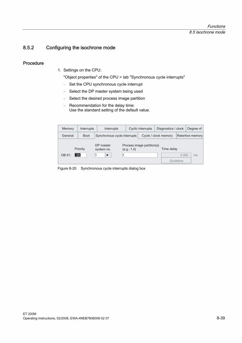
Functions 8.5 Isochrone mode
ET 200M Operating Instructions, 02/2006, EWA-4NEB7806006-02 07 8-39
8.5.2 Configuring the isochrone mode
Procedure 1. Settings on the CPU:
"Object properties" of the CPU > tab "Synchronous cycle interrupts" – Set the CPU synchronous cycle interrupt – Select the DP master system being used – Select the desired process image partition – Recommendation for the delay time:
Use the standard setting of the default value.
Figure 8-20 Synchronous cycle interrupts dialog box
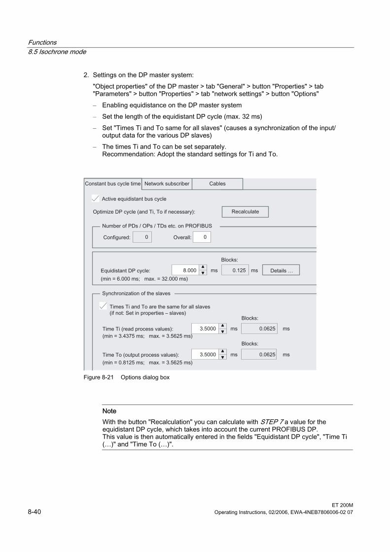
Functions 8.5 Isochrone mode
ET 200M 8-40 Operating Instructions, 02/2006, EWA-4NEB7806006-02 07
2. Settings on the DP master system: "Object properties" of the DP master > tab "General" > button "Properties" > tab "Parameters" > button "Properties" > tab "network settings" > button "Options" – Enabling equidistance on the DP master system – Set the length of the equidistant DP cycle (max. 32 ms) – Set "Times Ti and To same for all slaves" (causes a synchronization of the input/
output data for the various DP slaves) – The times Ti and To can be set separately.
Recommendation: Adopt the standard settings for Ti and To.
Figure 8-21 Options dialog box
Note With the button "Recalculation" you can calculate with STEP 7 a value for the equidistant DP cycle, which takes into account the current PROFIBUS DP. This value is then automatically entered in the fields "Equidistant DP cycle", "Time Ti (…)" and "Time To (…)".
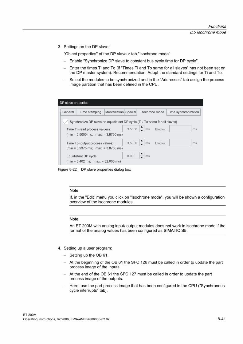
Functions 8.5 Isochrone mode
ET 200M Operating Instructions, 02/2006, EWA-4NEB7806006-02 07 8-41
3. Settings on the DP slave: "Object properties" of the DP slave > tab "Isochrone mode" – Enable "Synchronize DP slave to constant bus cycle time for DP cycle". – Enter the times Ti and To (if "Times Ti and To same for all slaves" has not been set on
the DP master system). Recommendation: Adopt the standard settings for Ti and To. – Select the modules to be synchronized and in the "Addresses" tab assign the process
image partition that has been defined in the CPU.
Figure 8-22 DP slave properties dialog box
Note If, in the "Edit" menu you click on "Isochrone mode", you will be shown a configuration overview of the isochrone modules.
Note An ET 200M with analog input/ output modules does not work in isochrone mode if the format of the analog values has been configured as SIMATIC S5.
4. Setting up a user program: – Setting up the OB 61. – At the beginning of the OB 61 the SFC 126 must be called in order to update the part
process image of the inputs. – At the end of the OB 61 the SFC 127 must be called in order to update the part
process image of the outputs. – Here, use the part process image that has been configured in the CPU ("Synchronous
cycle interrupts" tab).
Functions 8.5 Isochrone mode
ET 200M 8-42 Operating Instructions, 02/2006, EWA-4NEB7806006-02 07
Configuring overlapping of Ti and To With IM 153-2BAx1 in isochrone mode you can also configure an overlapping of the Ti and To. Configuring with STEP 7: The configuration takes place as described above. In addition you can configure an overlapping of the Ti and To. To do this, carry out the following deviating settings: 1. When configuring the DP master system:
deactivate the check box Times Ti and To same for all slaves. 2. When configuring the DP slave:
enter the times for Ti and To separately for each slave. An overlapping Ti and To is given if Ti + To > Tdp. STEP 7 checks the values you have entered for feasibility.
To locate reserves you can visualize the chronological sequences with the aid of a calculation table. In the result you can optimize the sequences accordingly. You´ll find the tables in the Internet under the address: http://support.automation.siemens.com/WW/view/de/10805299/133000
Note Liability disclaimer Siemens AG shall not be held liable for any damages resulting from the use of the calculation table; particularly for damage to persons, property or assets that are considered consequential damages resulting directly or indirectly in connection with the use of the calculation table. We offer no support for the application of the calculation table.
Parameterization with GSD configuring: If you have configured the IM 153-2BAx1 via the GSD file, you can use a calculation table to optimally adapt the configuration being used. You´ll find the tables in the Internet under the address: http://support.automation.siemens.com/WW/view/de/10805299/133000
Note Liability disclaimer Siemens AG shall not be held liable for any damages resulting from the use of the calculation table; particularly for damage to persons, property or assets that are considered consequential damages resulting directly or indirectly in connection with the use of the calculation table. We offer no support for the application of the calculation table.

Functions 8.6 Identification and maintenance data (I&M data)
ET 200M Operating Instructions, 02/2006, EWA-4NEB7806006-02 07 8-43
Time when using active bus modules
Note With IM 153-2 (6ES7153-2BAxx-0XB0) the use of active bus modules for an isochronic operation is not intended as the synchronization conditions for this application case are only fulfilled module-granular. However, if active bus modules are to be used, the user must incorporate in each case a time of 0.5 ms for Ti and To and therefore an equidistant DP cycle of 1 ms.
Additional information You can find more information about the isochrone mode in the online help for STEP 7 and in the Isochrone mode manual. You´ll find the function manual in the Internet under the address: http://support.automation.siemens.com Look for the report with the number 15218045.
8.6 8.6 Identification and maintenance data (I&M data)
Definition and properties Identification and maintenance data (I&M) are data that are stored in a module for assisting you in: • Checking the system configuration • Locating hardware changes in a system • Correcting errors in a system Identification data (I data) is information regarding the module, like for example, order number and serial number, which are partly also printed on the housing of the module. I data is manufacturer´s information on the module and can only be read. Maintenance data (M data) is system-dependent information, like for example, location and date of location. M data is created during the configuration and written to the module. I&M data enable modules to be uniquely identified online. As of IM 153-2Bx00 this data is available on the ET 200M.
Note Only one DP master can access the I&M data of an ET 200M at any one point.
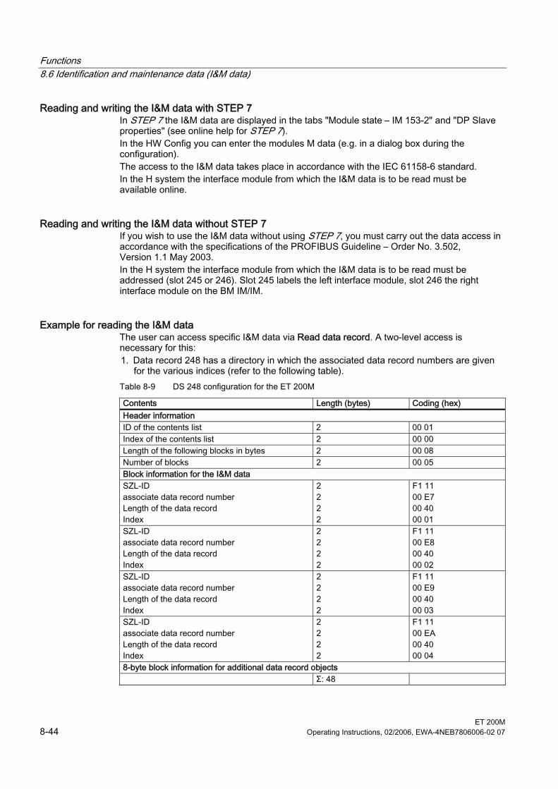
Functions 8.6 Identification and maintenance data (I&M data)
ET 200M 8-44 Operating Instructions, 02/2006, EWA-4NEB7806006-02 07
Reading and writing the I&M data with STEP 7 In STEP 7 the I&M data are displayed in the tabs "Module state – IM 153-2" and "DP Slave properties" (see online help for STEP 7). In the HW Config you can enter the modules M data (e.g. in a dialog box during the configuration). The access to the I&M data takes place in accordance with the IEC 61158-6 standard. In the H system the interface module from which the I&M data is to be read must be available online.
Reading and writing the I&M data without STEP 7 If you wish to use the I&M data without using STEP 7, you must carry out the data access in accordance with the specifications of the PROFIBUS Guideline – Order No. 3.502, Version 1.1 May 2003. In the H system the interface module from which the I&M data is to be read must be addressed (slot 245 or 246). Slot 245 labels the left interface module, slot 246 the right interface module on the BM IM/IM.
Example for reading the I&M data The user can access specific I&M data via Read data record. A two-level access is necessary for this: 1. Data record 248 has a directory in which the associated data record numbers are given
for the various indices (refer to the following table). Table 8-9 DS 248 configuration for the ET 200M
Contents Length (bytes) Coding (hex) Header information ID of the contents list 2 00 01 Index of the contents list 2 00 00 Length of the following blocks in bytes 2 00 08 Number of blocks 2 00 05 Block information for the I&M data SZL-ID associate data record number Length of the data record Index
2 2 2 2
F1 11 00 E7 00 40 00 01
SZL-ID associate data record number Length of the data record Index
2 2 2 2
F1 11 00 E8 00 40 00 02
SZL-ID associate data record number Length of the data record Index
2 2 2 2
F1 11 00 E9 00 40 00 03
SZL-ID associate data record number Length of the data record Index
2 2 2 2
F1 11 00 EA 00 40 00 04
8-byte block information for additional data record objects Σ: 48
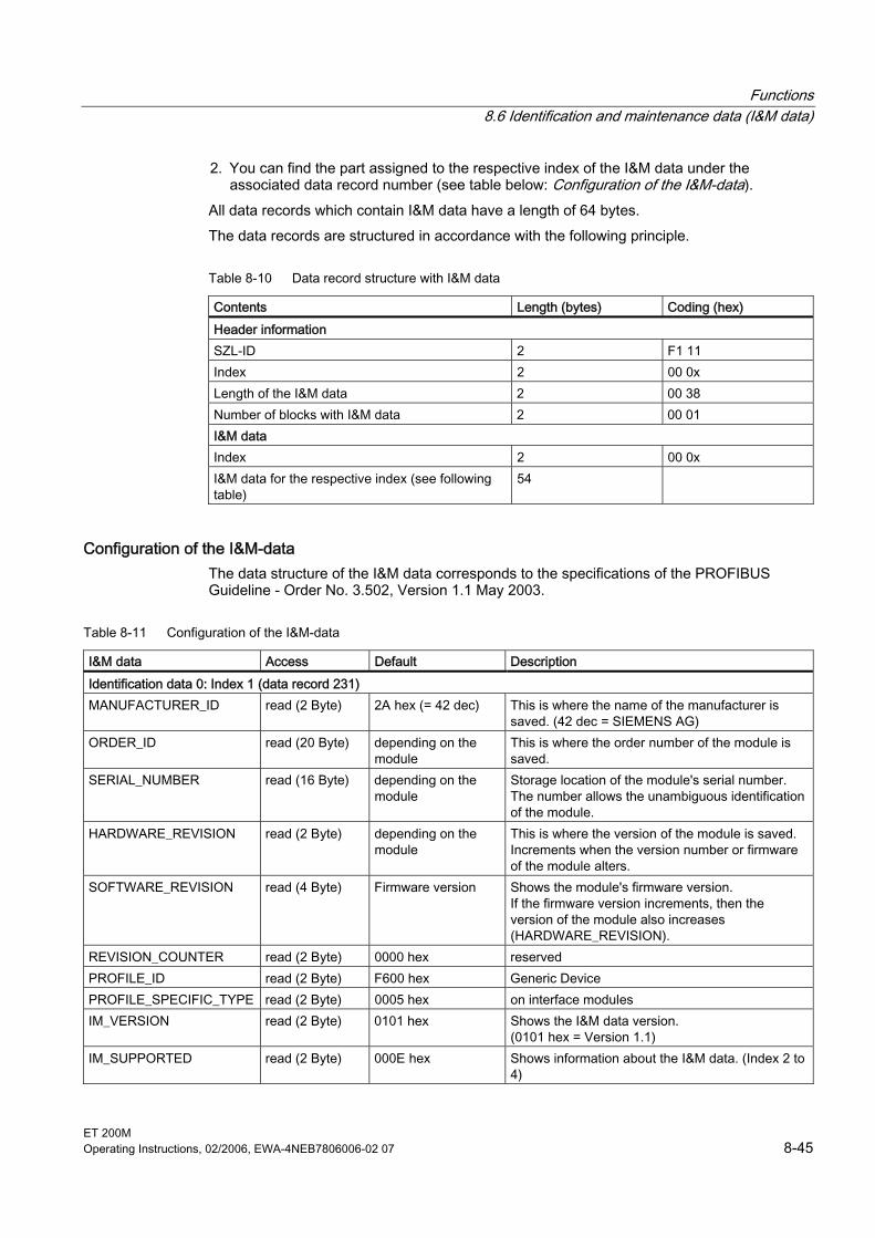
Functions 8.6 Identification and maintenance data (I&M data)
ET 200M Operating Instructions, 02/2006, EWA-4NEB7806006-02 07 8-45
2. You can find the part assigned to the respective index of the I&M data under the associated data record number (see table below: Configuration of the I&M-data).
All data records which contain I&M data have a length of 64 bytes. The data records are structured in accordance with the following principle.
Table 8-10 Data record structure with I&M data
Contents Length (bytes) Coding (hex) Header information SZL-ID 2 F1 11 Index 2 00 0x Length of the I&M data 2 00 38 Number of blocks with I&M data 2 00 01 I&M data Index 2 00 0x I&M data for the respective index (see following table)
54
Configuration of the I&M-data The data structure of the I&M data corresponds to the specifications of the PROFIBUS Guideline - Order No. 3.502, Version 1.1 May 2003.
Table 8-11 Configuration of the I&M-data
I&M data Access Default Description Identification data 0: Index 1 (data record 231) MANUFACTURER_ID read (2 Byte) 2A hex (= 42 dec) This is where the name of the manufacturer is
saved. (42 dec = SIEMENS AG) ORDER_ID read (20 Byte) depending on the
module This is where the order number of the module is saved.
SERIAL_NUMBER read (16 Byte) depending on the module
Storage location of the module's serial number. The number allows the unambiguous identification of the module.
HARDWARE_REVISION read (2 Byte) depending on the module
This is where the version of the module is saved. Increments when the version number or firmware of the module alters.
SOFTWARE_REVISION read (4 Byte) Firmware version Shows the module's firmware version. If the firmware version increments, then the version of the module also increases (HARDWARE_REVISION).
REVISION_COUNTER read (2 Byte) 0000 hex reserved PROFILE_ID read (2 Byte) F600 hex Generic Device PROFILE_SPECIFIC_TYPE read (2 Byte) 0005 hex on interface modules IM_VERSION read (2 Byte) 0101 hex Shows the I&M data version.
(0101 hex = Version 1.1) IM_SUPPORTED read (2 Byte) 000E hex Shows information about the I&M data. (Index 2 to
4)
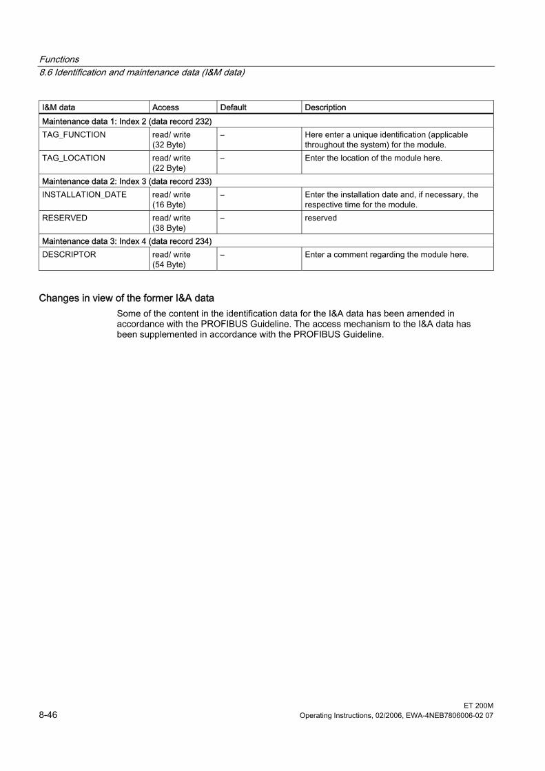
Functions 8.6 Identification and maintenance data (I&M data)
ET 200M 8-46 Operating Instructions, 02/2006, EWA-4NEB7806006-02 07
I&M data Access Default Description Maintenance data 1: Index 2 (data record 232) TAG_FUNCTION read/ write
(32 Byte) – Here enter a unique identification (applicable
throughout the system) for the module. TAG_LOCATION read/ write
(22 Byte) – Enter the location of the module here.
Maintenance data 2: Index 3 (data record 233) INSTALLATION_DATE read/ write
(16 Byte) – Enter the installation date and, if necessary, the
respective time for the module. RESERVED read/ write
(38 Byte) – reserved
Maintenance data 3: Index 4 (data record 234) DESCRIPTOR read/ write
(54 Byte) – Enter a comment regarding the module here.
Changes in view of the former I&A data Some of the content in the identification data for the I&A data has been amended in accordance with the PROFIBUS Guideline. The access mechanism to the I&A data has been supplemented in accordance with the PROFIBUS Guideline.
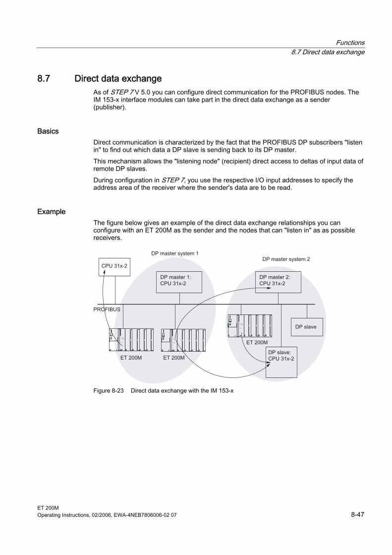
Functions 8.7 Direct data exchange
ET 200M Operating Instructions, 02/2006, EWA-4NEB7806006-02 07 8-47
8.7 8.7 Direct data exchange As of STEP 7 V 5.0 you can configure direct communication for the PROFIBUS nodes. The IM 153-x interface modules can take part in the direct data exchange as a sender (publisher).
Basics Direct communication is characterized by the fact that the PROFIBUS DP subscribers "listen in" to find out which data a DP slave is sending back to its DP master. This mechanism allows the "listening node" (recipient) direct access to deltas of input data of remote DP slaves. During configuration in STEP 7, you use the respective I/O input addresses to specify the address area of the receiver where the sender's data are to be read.
Example The figure below gives an example of the direct data exchange relationships you can configure with an ET 200M as the sender and the nodes that can "listen in" as as possible receivers.
Figure 8-23 Direct data exchange with the IM 153-x
Functions 8.8 Direct data exchange with F modules (fail-safe I slave-slave communication)
ET 200M 8-48 Operating Instructions, 02/2006, EWA-4NEB7806006-02 07
8.8 8.8 Direct data exchange with F modules (fail-safe I slave-slave communication)
Principle of operation The node function (Subscriber) of the IM 153-2Bxx1 makes it possible for direct data exchange with F modules in an ET200 M. If direct data exchange is configured for an F module, the data will be exchanged - whilst incorporating the IM 153-2 - directly between the I slave and the F module. Direct data exchange is not possible • between two F modules
– with an ET 200M station – in different ET 200M stations
• with an F module in a redundantly structured ET 200M station
Conditions The following conditions apply for a fail-safe I slave-slave communication:
Table 8-12 Conditions for a fail-safe I slave-slave communication
Isochronous If direct data exchange is enabled at the same time as isochrone mode, then the STEP 7 takes this into account when calculating the cycle times.
Configuration change in RUN (CiR) CiR is possible if direct data exchange is configured. To do this, the DP master must make available the prepared data. It is not permitted with CiR to add or remove safe I slave-slave communication relationships.
Output data for the F module Data is completely transferred to the F module either • from the DP master • or via direct data exchange
Configuring Direct data exchange with F-modules can only be configured with STEP 7, it is not possible to configure via a GSD file. In addition to STEP 7, the optional package S7 Distributed Safety must be installed on the engineering station.
Operating steps for activation The operating steps for enabling the direct data exchange with the F modules are described in the programming and operating manual S7 Distributed Safety, Configuring and Programming under Fail-safe I slave-slave communication. You´ll find the manual in the Internet under the address: http://support.automation.siemens.com Look for the report with the number 22099875.
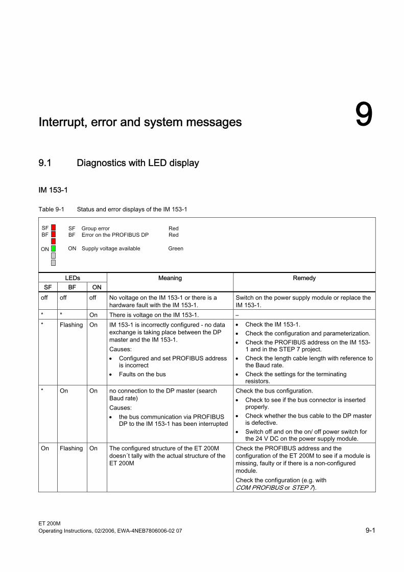
ET 200M Operating Instructions, 02/2006, EWA-4NEB7806006-02 07 9-1
Interrupt, error and system messages 99.1 9.1 Diagnostics with LED display
IM 153-1
Table 9-1 Status and error displays of the IM 153-1
SFBF
ON
LEDs SF BF ON
Meaning Remedy
off off off No voltage on the IM 153-1 or there is a hardware fault with the IM 153-1.
Switch on the power supply module or replace the IM 153-1.
* * On There is voltage on the IM 153-1. – * Flashing On IM 153-1 is incorrectly configured - no data
exchange is taking place between the DP master and the IM 153-1. Causes: • Configured and set PROFIBUS address
is incorrect • Faults on the bus
• Check the IM 153-1. • Check the configuration and parameterization. • Check the PROFIBUS address on the IM 153-
1 and in the STEP 7 project. • Check the length cable length with reference to
the Baud rate. • Check the settings for the terminating
resistors. * On On no connection to the DP master (search
Baud rate) Causes: • the bus communication via PROFIBUS
DP to the IM 153-1 has been interrupted
Check the bus configuration. • Check to see if the bus connector is inserted
properly. • Check whether the bus cable to the DP master
is defective. • Switch off and on the on/ off power switch for
the 24 V DC on the power supply module. On Flashing On The configured structure of the ET 200M
doesn´t tally with the actual structure of the ET 200M
Check the PROFIBUS address and the configuration of the ET 200M to see if a module is missing, faulty or if there is a non-configured module. Check the configuration (e.g. with COM PROFIBUS or STEP 7).
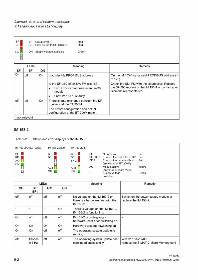
Interrupt, error and system messages 9.1 Diagnostics with LED display
ET 200M 9-2 Operating Instructions, 02/2006, EWA-4NEB7806006-02 07
SFBF
ON
LEDs SF BF ON
Meaning Remedy
On off On inadmissible PROFIBUS address Is the SF LED of an SM/ FM also lit? • If so: Error or diagnosis in an S7-300
module • If not: IM 153-1 is faulty.
On the IM 153-1 set a valid PROFIBUS address (1 to 125) Check the SM/ FM with the diagnostics. Replace the S7-300 module or the IM 153-1 or contact your Siemens representative.
off off On There is data exchange between the DP master and the ET 200M. The preset configuration and actual configuration of the ET 200M match.
–
* not relevant
IM 153-2
Table 9-2 Status and error displays of the IM 153-2
LEDs SF BF/
BF1 ACT ON
Meaning Remedy
off off off off No voltage on the IM 153-2 or there is a hardware fault with the IM 153-2.
Switch on the power supply module or replace the IM 153-2.
* * * On There is voltage on the IM 153-2. IM 153-2 is functioning.
–
On off off off IM 153-2 is undergoing a hardware reset after switching on
–
On On On On Hardware test after switching on – On On off off The operating system update is
running –
off flashes 0.5 Hz
off off The operating system update has concluded successfully
with IM 153-2Bx00: remove the SIMATIC Micro Memory card
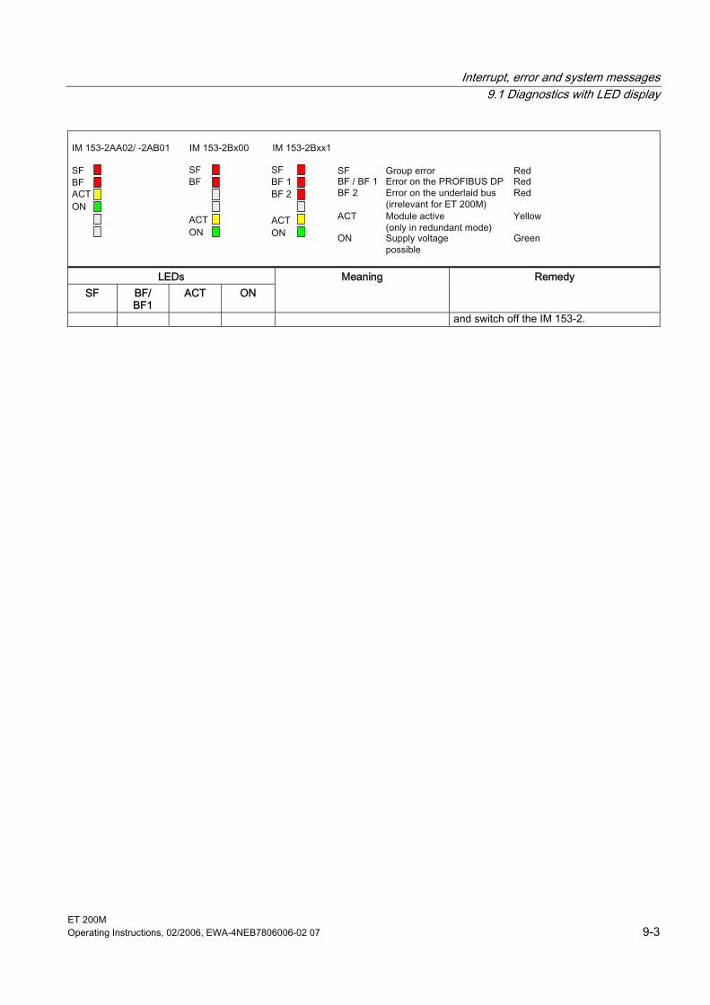
Interrupt, error and system messages 9.1 Diagnostics with LED display
ET 200M Operating Instructions, 02/2006, EWA-4NEB7806006-02 07 9-3
LEDs SF BF/
BF1 ACT ON
Meaning Remedy
and switch off the IM 153-2.
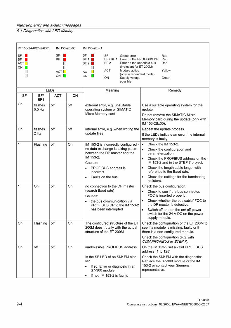
Interrupt, error and system messages 9.1 Diagnostics with LED display
ET 200M 9-4 Operating Instructions, 02/2006, EWA-4NEB7806006-02 07
LEDs SF BF/
BF1 ACT ON
Meaning Remedy
On flashes 0.5 Hz
off off external error, e.g. unsuitable operating system or SIMATIC Micro Memory card
Use a suitable operating system for the update. Do not remove the SIMATIC Micro Memory card during the update (only with IM 153-2Bx00).
On flashes 2 Hz
off off internal error, e.g. when writing the update files
Repeat the update process. If the LEDs indicate an error, the internal memory is faulty.
* Flashing off On IM 153-2 is incorrectly configured - no data exchange is taking place between the DP master and the IM 153-2. Causes: • PROFIBUS address is
incorrect • Faults on the bus.
• Check the IM 153-2. • Check the configuration and
parameterization. • Check the PROFIBUS address on the
IM 153-2 and in the STEP 7 project. • Check the length cable length with
reference to the Baud rate. • Check the settings for the terminating
resistors. * On off On no connection to the DP master
(search Baud rate) Causes: • the bus communication via
PROFIBUS DP to the IM 153-2 has been interrupted
Check the bus configuration. • Check to see if the bus connector/
FOC is inserted properly. • Check whether the bus cable/ FOC to
the DP master is defective. • Switch off and on the on/ off power
switch for the 24 V DC on the power supply module.
On Flashing off On The configured structure of the ET 200M doesn´t tally with the actual structure of the ET 200M
Check the configuration of the ET 200M to see if a module is missing, faulty or if there is a non-configured module. Check the configuration (e.g. with COM PROFIBUS or STEP 7).
On off off On inadmissible PROFIBUS address Is the SF LED of an SM/ FM also lit? • If so: Error or diagnosis in an
S7-300 module • If not: IM 153-2 is faulty.
On the IM 153-2 set a valid PROFIBUS address (1 to 125) Check the SM/ FM with the diagnostics. Replace the S7-300 module or the IM 153-2 or contact your Siemens representative.
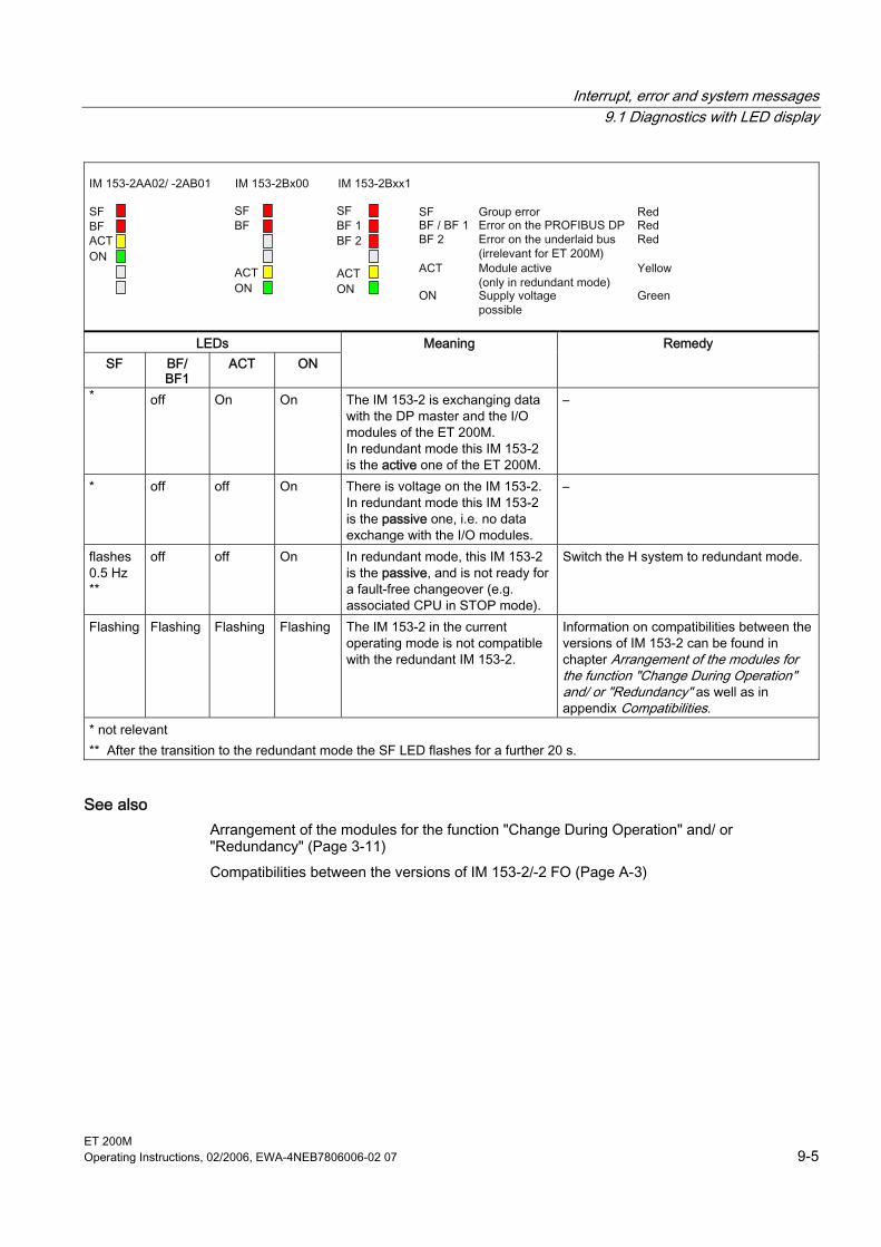
Interrupt, error and system messages 9.1 Diagnostics with LED display
ET 200M Operating Instructions, 02/2006, EWA-4NEB7806006-02 07 9-5
LEDs SF BF/
BF1 ACT ON
Meaning Remedy
* off On On The IM 153-2 is exchanging data with the DP master and the I/O modules of the ET 200M. In redundant mode this IM 153-2 is the active one of the ET 200M.
–
* off off On There is voltage on the IM 153-2. In redundant mode this IM 153-2 is the passive one, i.e. no data exchange with the I/O modules.
–
flashes 0.5 Hz **
off off On In redundant mode, this IM 153-2 is the passive, and is not ready for a fault-free changeover (e.g. associated CPU in STOP mode).
Switch the H system to redundant mode.
Flashing Flashing Flashing Flashing The IM 153-2 in the current operating mode is not compatible with the redundant IM 153-2.
Information on compatibilities between the versions of IM 153-2 can be found in chapter Arrangement of the modules for the function "Change During Operation" and/ or "Redundancy" as well as in appendix Compatibilities.
* not relevant ** After the transition to the redundant mode the SF LED flashes for a further 20 s.
See also Arrangement of the modules for the function "Change During Operation" and/ or "Redundancy" (Page 3-11) Compatibilities between the versions of IM 153-2/-2 FO (Page A-3)
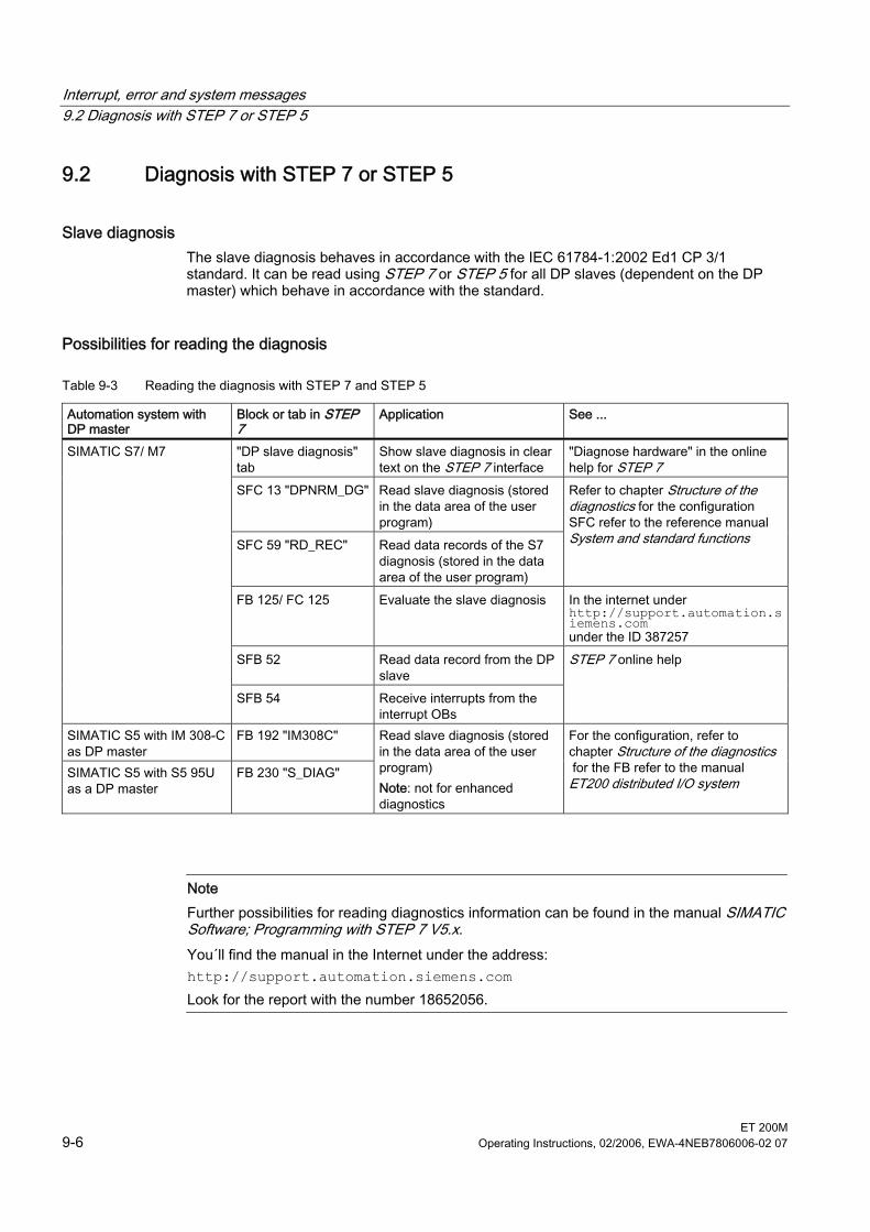
Interrupt, error and system messages 9.2 Diagnosis with STEP 7 or STEP 5
ET 200M 9-6 Operating Instructions, 02/2006, EWA-4NEB7806006-02 07
9.2 9.2 Diagnosis with STEP 7 or STEP 5
Slave diagnosis The slave diagnosis behaves in accordance with the IEC 61784-1:2002 Ed1 CP 3/1 standard. It can be read using STEP 7 or STEP 5 for all DP slaves (dependent on the DP master) which behave in accordance with the standard.
Possibilities for reading the diagnosis
Table 9-3 Reading the diagnosis with STEP 7 and STEP 5
Automation system with DP master
Block or tab in STEP 7
Application See ...
"DP slave diagnosis" tab
Show slave diagnosis in clear text on the STEP 7 interface
"Diagnose hardware" in the online help for STEP 7
SFC 13 "DPNRM_DG" Read slave diagnosis (stored in the data area of the user program)
SFC 59 "RD_REC" Read data records of the S7 diagnosis (stored in the data area of the user program)
Refer to chapter Structure of the diagnostics for the configuration SFC refer to the reference manual System and standard functions
FB 125/ FC 125 Evaluate the slave diagnosis In the internet under http://support.automation.siemens.com under the ID 387257
SFB 52 Read data record from the DP slave
SIMATIC S7/ M7
SFB 54 Receive interrupts from the interrupt OBs
STEP 7 online help
SIMATIC S5 with IM 308-C as DP master
FB 192 "IM308C"
SIMATIC S5 with S5 95U as a DP master
FB 230 "S_DIAG"
Read slave diagnosis (stored in the data area of the user program) Note: not for enhanced diagnostics
For the configuration, refer to chapter Structure of the diagnostics for the FB refer to the manual ET200 distributed I/O system
Note Further possibilities for reading diagnostics information can be found in the manual SIMATIC Software; Programming with STEP 7 V5.x. You´ll find the manual in the Internet under the address: http://support.automation.siemens.com Look for the report with the number 18652056.
Interrupt, error and system messages 9.2 Diagnosis with STEP 7 or STEP 5
ET 200M Operating Instructions, 02/2006, EWA-4NEB7806006-02 07 9-7
Example for reading the S7 diagnosis with SFC 13 "DPNRM_DG" Here you will find an example of how to use the SFC 13 to read the slave diagnosis for a DP slave in the STEP 7 user program. Assumptions The following assumptions apply to this STEP 7 user program: • The diagnosis address of the ET 200M is 1022 (3FEH). • The slave diagnosis should be stored in the DB 82:
as of address 0.0, length 64 bytes. • The slave diagnosis consists of 64 bytes. STEP 7 user program
STL Description CALL SFC 13 REQ :=TRUE Read request LADDR :=W#16#3FE Diagnosis address of the ET 200M RET_VAL := MW 0 RET_VAL of SFC 13 RECORD :=P#DB82.DBX 0.0 BYTE 64 Data record for the diagnosis in the DB 82 BUSY :=M2.0 Reading process runs through several OB 1
cycles
Example for reading the slave diagnosis with FB 192 "IM308C" Here you will find an example of how to use the FB 192 to read the slave diagnosis for a DP slave in the STEP 5 user program. Assumptions The following assumptions apply to this STEP 5 user program: • The IM 308-C connection as a DP master occupies the frames 0 ... 15 (number 0 of the
IM 308-C). • The DP slave has the PROFIBUS address 3. • The slave diagnosis should be stored in the DB 20. You can also use any other data
block for this. • The slave diagnosis consists of 29 bytes. STEP 5 user program
STL Description :A DB 30 :SPA FB 192 Name :IM308C DPAD : KH F800 Default address area for the IM 308-C IMST : KY 0, 3 IM no. = 0, PROFIBUS address of the DP slave = 3 FCT : KC SD Function: Read slave diagnosis GCGR : KM 0 is not evaluated TYPE : KY 0, 20 S5 data area: DB 20 STAD : KF +1 Diagnosis data as of data word 1 LENG : KF -1 Diagnosis length = joker length (all permissible
bytes) ERR : DW 0 Error code storage in the DW 0 of the DB 30
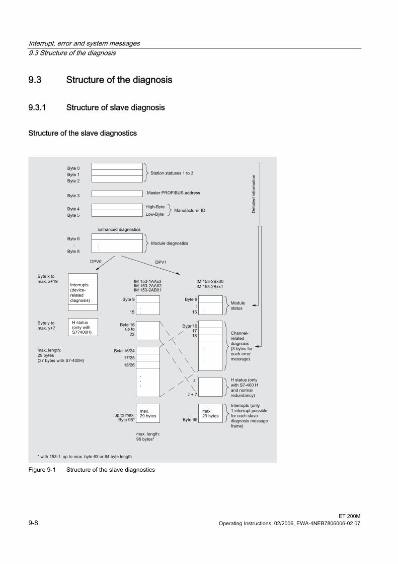
Interrupt, error and system messages 9.3 Structure of the diagnosis
ET 200M 9-8 Operating Instructions, 02/2006, EWA-4NEB7806006-02 07
9.3 9.3 Structure of the diagnosis
9.3.1 Structure of slave diagnosis
Structure of the slave diagnostics
Figure 9-1 Structure of the slave diagnostics

Interrupt, error and system messages 9.3 Structure of the diagnosis
ET 200M Operating Instructions, 02/2006, EWA-4NEB7806006-02 07 9-9
Slave diagnosis in accordance with standard The IM 153-x makes available to you the slave diagnosis in accordance with the standard. Observe the differences in the diagnostic frame in dependence on the version of the IM 153-x and of the general version. In dependence on the DP master and the configuration the interface module IM 153-1 as of 153-1AA03, module version 02, GSD-Version V1.18; IM 153-1 as of 153-1AA83, module version 01, GSD-Version V1.18; IM 153-2 as of 153-2AA02, module version > 06, GSD-Version V1.9; IM 153-2 FO as of 153-2AB01, module version > 05 , GSD-Version V1.5; IM 153-2 as of 153-2BA00, module version ≥ 01, GSD-Version V1.0; IM 153-2 FO as of 153-2BB00, module version ≥ 01, GSD-Version V1.0 IM 153-2 as of 153-2BA01, module version ≥ 01, GSD-Version V1.0; IM 153-2 as of 153-2BA81, module version ≥ 01, GSD-Version V1.0; provide an enhanced diagnosis. Here, in the diagnostic frame you will find detailed information in the form of the module status and channel-specific diagnoses (refer to figure above).
Information on "enhanced diagnosis" To be able to use the channel-specific diagnosis, you must enable the diagnostic interrupts for each I/O module of the configuration. When configuring the IM 153-x you can enable or block the diagnostic, process and removal insertion interrupts and you can do this independently of the enabling of "enhanced diagnosis". Via the DPV1 parameter (as of GSD rev. 3) you can block or enable the individual blocks of the enhanced diagnosis. Blocked diagnoses will be removed from the diagnostic frame. Important: If you have enabled "enhanced diagnosis" during the configuration and a diagnostic interrupt is triggered for a module only whilst the ET 200M is running, a channel error will not be immediately entered in the diagnostic frame. Only after the triggering of the first diagnostic interrupt of the module, generated after enabling, is a channel error entered in the diagnostic frame . In order to delete channel errors from the diagnostic frame you must switch off the "enhanced diagnosis" in the configuration.
IM 153-2Bx00 and IM 153-2Bxx1 With IM 153-2Bx00 and IM 153-2Bxx1 the enhanced diagnosis is available as default in the DPV0/ DPV1 mode. It can be deselected (switched off) in blocks during the configuration.
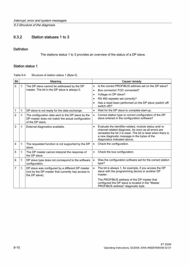
Interrupt, error and system messages 9.3 Structure of the diagnosis
ET 200M 9-10 Operating Instructions, 02/2006, EWA-4NEB7806006-02 07
9.3.2 Station statuses 1 to 3
Definition The stations status 1 to 3 provides an overview of the status of a DP slave.
Station status 1
Table 9-4 Structure of station status 1 (Byte 0)
Bit Meaning Cause/ remedy 0 1: The DP slave cannot be addressed by the DP
master. The bit in the DP slave is always 0. • Is the correct PROFIBUS address set on the DP slave? • Bus connector/ FOC connected? • Voltage on DP slave? • RS 485 repeater set correctly? • Has a reset been performed on the DP slave (switch off/
switch off)? 1 1: DP slave is not ready for the data exchange. • Wait for the DP slave to complete start-up. 2 1: The configuration data sent to the DP slave by the
DP master does not match the actual configuration of the DP slave.
• Correct station type or correct configuration of the DP slave entered in the configuration software?
3 1: External diagnostics available. • Evaluate the identifier-related, module status and/ or channel-related diagnosis. As soon as all errors are remedied the bit 3 is reset. The bit is reset when there is a new diagnostic message in the bytes of the diagnostics indicated above.
4 1: The requested function is not supported by the DP slave.
• Check the configuration.
5 1: The DP master cannot interpret the response of the DP slave.
• Check the bus configuration.
6 1: DP slave type does not correspond to the software configuration.
• Was the configuration software set for the correct station type?
7 1: DP slave was configured by a different DP master (not by the DP master that currently has access to the DP slave).
• The bit is always 1, for example, if you access the DP slave with the programming device or another DP master.
The PROFIBUS address of the DP master that configured the DP slave is located in the "Master PROFIBUS address" diagnostic byte.
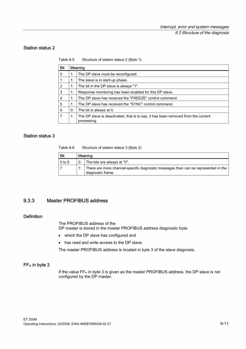
Interrupt, error and system messages 9.3 Structure of the diagnosis
ET 200M Operating Instructions, 02/2006, EWA-4NEB7806006-02 07 9-11
Station status 2
Table 9-5 Structure of station status 2 (Byte 1)
Bit Meaning 0 1: The DP slave must be reconfigured. 1 1: The slave is in start-up phase. 2 1: The bit in the DP slave is always "1". 3 1: Response monitoring has been enabled for this DP slave. 4 1: The DP slave has received the "FREEZE" control command. 5 1: The DP slave has received the "SYNC" control command. 6 0: The bit is always at 0. 7 1: The DP slave is deactivated, that is to say, it has been removed from the current
processing.
Station status 3
Table 9-6 Structure of station status 3 (Byte 2)
Bit Meaning 0 to 6 0: The bits are always at "0". 7 1: There are more channel-specific diagnostic messages than can be represented in the
diagnostic frame.
9.3.3 Master PROFIBUS address
Definition The PROFIBUS address of the DP master is stored in the master PROFIBUS address diagnostic byte: • which the DP slave has configured and • has read and write access to the DP slave. The master PROFIBUS address is located in byte 3 of the slave diagnosis.
FFH in byte 3 If the value FFH in byte 3 is given as the master PROFIBUS address, the DP slave is not configured by the DP master.
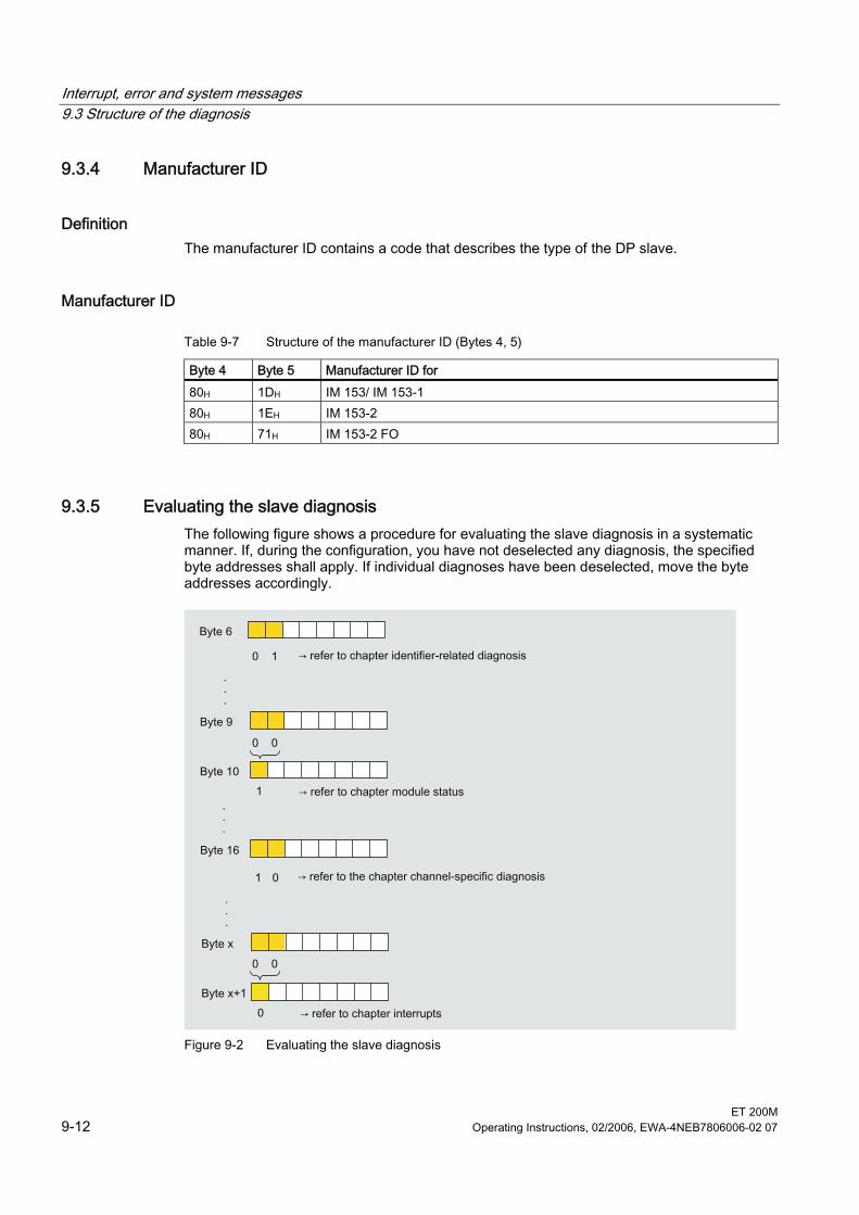
Interrupt, error and system messages 9.3 Structure of the diagnosis
ET 200M 9-12 Operating Instructions, 02/2006, EWA-4NEB7806006-02 07
9.3.4 Manufacturer ID
Definition The manufacturer ID contains a code that describes the type of the DP slave.
Manufacturer ID
Table 9-7 Structure of the manufacturer ID (Bytes 4, 5)
Byte 4 Byte 5 Manufacturer ID for 80H 1DH IM 153/ IM 153-1 80H 1EH IM 153-2 80H 71H IM 153-2 FO
9.3.5 Evaluating the slave diagnosis The following figure shows a procedure for evaluating the slave diagnosis in a systematic manner. If, during the configuration, you have not deselected any diagnosis, the specified byte addresses shall apply. If individual diagnoses have been deselected, move the byte addresses accordingly.
Figure 9-2 Evaluating the slave diagnosis
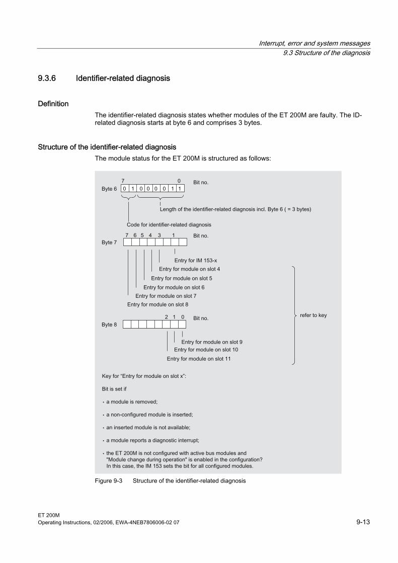
Interrupt, error and system messages 9.3 Structure of the diagnosis
ET 200M Operating Instructions, 02/2006, EWA-4NEB7806006-02 07 9-13
9.3.6 Identifier-related diagnosis
Definition The identifier-related diagnosis states whether modules of the ET 200M are faulty. The ID-related diagnosis starts at byte 6 and comprises 3 bytes.
Structure of the identifier-related diagnosis The module status for the ET 200M is structured as follows:
Figure 9-3 Structure of the identifier-related diagnosis
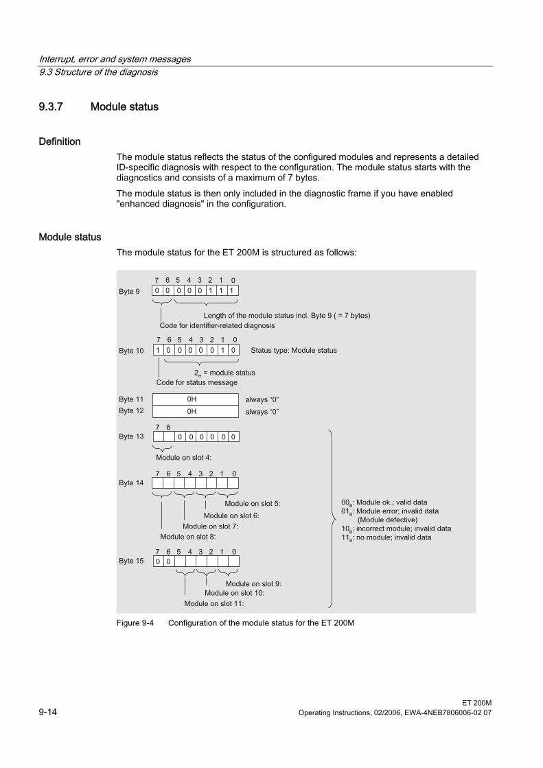
Interrupt, error and system messages 9.3 Structure of the diagnosis
ET 200M 9-14 Operating Instructions, 02/2006, EWA-4NEB7806006-02 07
9.3.7 Module status
Definition The module status reflects the status of the configured modules and represents a detailed ID-specific diagnosis with respect to the configuration. The module status starts with the diagnostics and consists of a maximum of 7 bytes. The module status is then only included in the diagnostic frame if you have enabled "enhanced diagnosis" in the configuration.
Module status The module status for the ET 200M is structured as follows:
Figure 9-4 Configuration of the module status for the ET 200M

Interrupt, error and system messages 9.3 Structure of the diagnosis
ET 200M Operating Instructions, 02/2006, EWA-4NEB7806006-02 07 9-15
9.3.8 Channel-specific diagnostics
Definition The channel-specific diagnosis gives information about channel errors of modules and represents detailed information for the identifier-related diagnosis. The channel-specific diagnosis starts according to the module status or the H status. The channel-specific diagnosis does not influence the module status. Important: the diagnostic interrupt must be switched on for each module!
Channel-specific diagnostics The channel-specific diagnosis is then included in the diagnostic frame only if you have enabled "enhanced diagnosis" in the configuration. The maximum number of channel-specific diagnoses is restricted by the maximum overall length of the slave diagnosis of 64 bytes with IM 153-1 or 96 bytes with IM 153-2. The length of the slave diagnosis depends on the number of current channel-specific diagnosis. Tip: If, when configuring the ET 200M, you block the interrupts, then up to 29 bytes interrupt part is also available for the channel-specific diagnoses.
Note Errors that affect all the channels of a module (e.g. the supply voltage of the module fails) will be portrayed in the channel-specific diagnosis only on channel 0. This then reduces the number of channel-specific diagnoses and prevents a "diagnostic overflow".
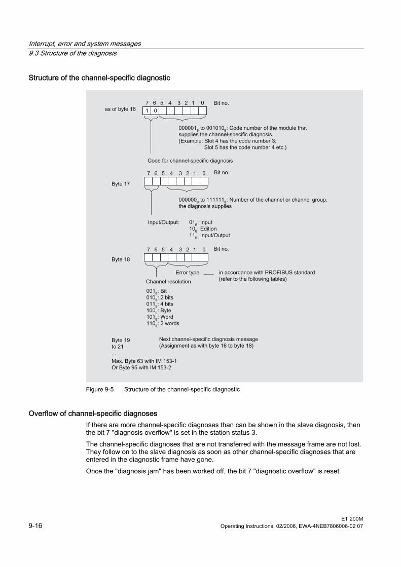
Interrupt, error and system messages 9.3 Structure of the diagnosis
ET 200M 9-16 Operating Instructions, 02/2006, EWA-4NEB7806006-02 07
Structure of the channel-specific diagnostic
Figure 9-5 Structure of the channel-specific diagnostic
Overflow of channel-specific diagnoses If there are more channel-specific diagnoses than can be shown in the slave diagnosis, then the bit 7 "diagnosis overflow" is set in the station status 3. The channel-specific diagnoses that are not transferred with the message frame are not lost. They follow on to the slave diagnosis as soon as other channel-specific diagnoses that are entered in the diagnostic frame have gone. Once the "diagnosis jam" has been worked off, the bit 7 "diagnostic overflow" is reset.
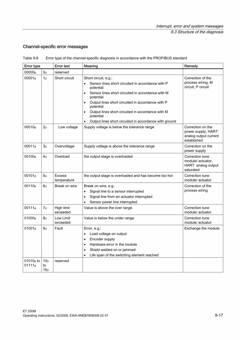
Interrupt, error and system messages 9.3 Structure of the diagnosis
ET 200M Operating Instructions, 02/2006, EWA-4NEB7806006-02 07 9-17
Channel-specific error messages
Table 9-8 Error type of the channel-specific diagnosis in accordance with the PROFIBUS standard
Error type Error text Meaning Remedy 00000B 0D reserved 00001B 1D Short circuit Short circuit, e.g.:
• Sensor lines short circuited in accordance with P potential
• Sensor lines short circuited in accordance with M potential
• Output lines short circuited in accordance with P potential
• Output lines short circuited in accordance with M potential
• Output lines short circuited in accordance with ground
Correction of the process wiring, M circuit, P circuit
00010B 2D Low voltage Supply voltage is below the tolerance range Correction on the power supply, HART: analog output current established
00011B 3D Overvoltage Supply voltage is above the tolerance range Correction on the power supply
00100B 4D Overload the output stage is overloaded Correction tune module/ actuator, HART: analog output saturated
00101B 5D Excess temperature
the output stage is overloaded and has become too hot Correction tune module/ actuator
00110B 6D Break on wire Break on wire, e.g.: • Signal line to a sensor interrupted • Signal line from an actuator interrupted • Sensor power line interrupted
Correction of the process wiring
00111B 7D High limit exceeded
Value is above the over range Correction tune module/ actuator
01000B 8D Low Limit exceeded
Value is below the under range Correction tune module/ actuator
01001B 9D Fault Error, e.g.: • Load voltage on output • Encoder supply • Hardware error in the module • Shield welded on or jammed • Life span of the switching element reached
Exchange the module
01010B to 01111B
10D to 15D
reserved
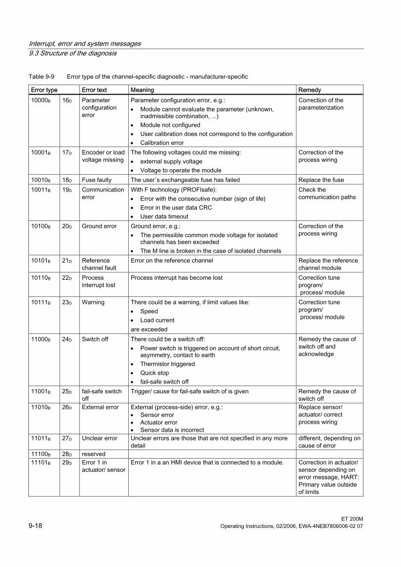
Interrupt, error and system messages 9.3 Structure of the diagnosis
ET 200M 9-18 Operating Instructions, 02/2006, EWA-4NEB7806006-02 07
Table 9-9 Error type of the channel-specific diagnostic - manufacturer-specific
Error type Error text Meaning Remedy 10000B 16D Parameter
configuration error
Parameter configuration error, e.g.: • Module cannot evaluate the parameter (unknown,
inadmissible combination, ...) • Module not configured • User calibration does not correspond to the configuration • Calibration error
Correction of the parameterization
10001B 17D Encoder or load voltage missing
The following voltages could me missing: • external supply voltage • Voltage to operate the module
Correction of the process wiring
10010B 18D Fuse faulty The user´s exchangeable fuse has failed Replace the fuse 10011B 19D Communication
error With F technology (PROFIsafe): • Error with the consecutive number (sign of life) • Error in the user data CRC • User data timeout
Check the communication paths
10100B 20D Ground error Ground error, e.g.: • The permissible common mode voltage for isolated
channels has been exceeded • The M line is broken in the case of isolated channels
Correction of the process wiring
10101B 21D Reference channel fault
Error on the reference channel Replace the reference channel module
10110B 22D Process interrupt lost
Process interrupt has become lost Correction tune program/ process/ module
10111B 23D Warning There could be a warning, if limit values like: • Speed • Load current are exceeded
Correction tune program/ process/ module
11000B 24D Switch off There could be a switch off: • Power switch is triggered on account of short circuit,
asymmetry, contact to earth • Thermistor triggered • Quick stop • fail-safe switch off
Remedy the cause of switch off and acknowledge
11001B 25D fail-safe switch off
Trigger/ cause for fail-safe switch of is given Remedy the cause of switch off
11010B 26D External error External (process-side) error, e.g.: • Sensor error • Actuator error • Sensor data is incorrect
Replace sensor/ actuator/ correct process wiring
11011B 27D Unclear error Unclear errors are those that are not specified in any more detail
different, depending on cause of error
11100B 28D reserved 11101B 29D Error 1 in
actuator/ sensor Error 1 in a an HMI device that is connected to a module. Correction in actuator/
sensor depending on error message, HART: Primary value outside of limits
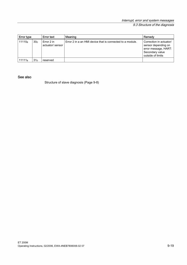
Interrupt, error and system messages 9.3 Structure of the diagnosis
ET 200M Operating Instructions, 02/2006, EWA-4NEB7806006-02 07 9-19
Error type Error text Meaning Remedy 11110B 30D Error 2 in
actuator/ sensor Error 2 in a an HMI device that is connected to a module. Correction in actuator/
sensor depending on error message, HART: Secondary value outside of limits
11111B 31D reserved
See also Structure of slave diagnosis (Page 9-8)
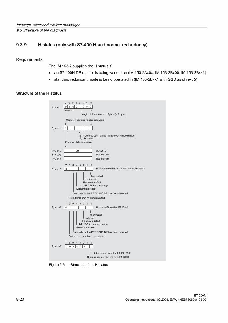
Interrupt, error and system messages 9.3 Structure of the diagnosis
ET 200M 9-20 Operating Instructions, 02/2006, EWA-4NEB7806006-02 07
9.3.9 H status (only with S7-400 H and normal redundancy)
Requirements The IM 153-2 supplies the H status if • an S7-400H DP master is being worked on (IM 153-2Ax0x, IM 153-2Bx00, IM 153-2Bxx1) • standard redundant mode is being operated in (IM 153-2Bxx1 with GSD as of rev. 5)
Structure of the H status
Figure 9-6 Structure of the H status
Interrupt, error and system messages 9.3 Structure of the diagnosis
ET 200M Operating Instructions, 02/2006, EWA-4NEB7806006-02 07 9-21
9.3.10 Interrupts
Definition The interrupt part of the slave diagnosis gives information about the interrupt type and the cause of interrupt that has caused the slave diagnosis to trigger. The interrupt part encompasses a maximum of 29 bytes. A maximum of 1 alarm can be reported for each slave diagnosis.
Position in the diagnosis telegram The position of the interrupt part in the slave diagnosis depends on the configuration of the diagnosis frame and on the number of channel-specific diagnoses. The interrupt part is always the last part in the diagnosis frame
Contents The contents of the interrupt information depend on the interrupt type: With diagnosis interrupts (as of byte x+4) the diagnostics data record 1 for SIMATIC S7 (e.g. 16 bytes) is sent as additional interrupt information. For digital and analog modules you will find the meaning of the bytes in the figures below. With process interrupts the length of the additional interrupt information is 4 bytes. The meaning of these bytes can be found in the figures below. With end of cycle interrupts, these bytes are always FFH. With removal/ insert interrupts the length of the additional interrupt information is 5 bytes. The meaning of these bytes can be found in the figures below.
Removing and inserting interrupts In order to be able to insert and remove modules during operation you must configure the ET 200M with active bus modules. With the switch "Removing and inserting interrupts" you can configure whether the removal or insertion events are to be reported as an interrupt in the diagnostics frame. If you block "Removing and inserting interrupts", then in an active bus module configuration it is still possible to insert and remove modules. These events will then be portrayed exclusively on the identifier-related diagnosis and module status. Information on the behavior of the older IM 153-x versions can be found in the Compatibilities appendix. In a configuration with active bus modules, each removal and insertion of modules causes the station to fail.
Note If you insert or remove a dummy module DM 370, then no inserting or removing interrupt is triggered.
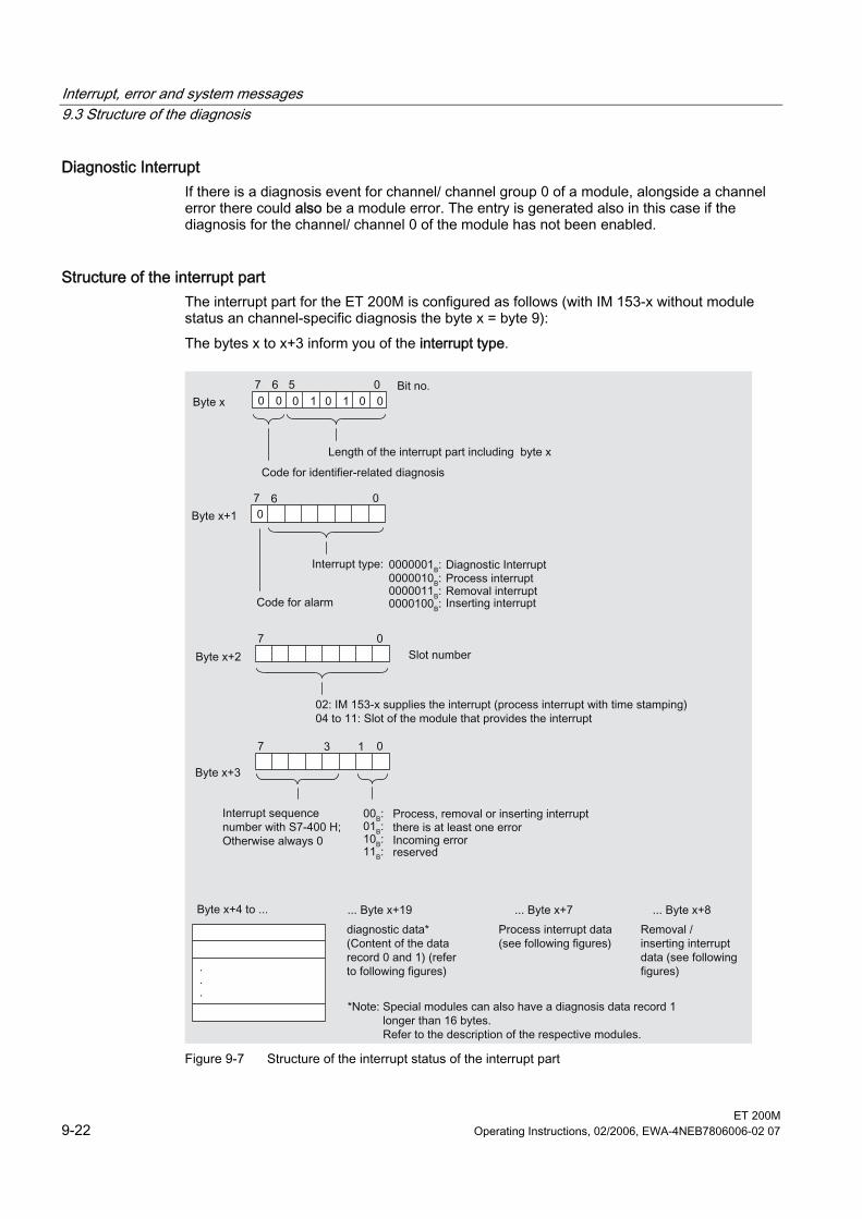
Interrupt, error and system messages 9.3 Structure of the diagnosis
ET 200M 9-22 Operating Instructions, 02/2006, EWA-4NEB7806006-02 07
Diagnostic Interrupt If there is a diagnosis event for channel/ channel group 0 of a module, alongside a channel error there could also be a module error. The entry is generated also in this case if the diagnosis for the channel/ channel 0 of the module has not been enabled.
Structure of the interrupt part The interrupt part for the ET 200M is configured as follows (with IM 153-x without module status an channel-specific diagnosis the byte x = byte 9): The bytes x to x+3 inform you of the interrupt type.
Figure 9-7 Structure of the interrupt status of the interrupt part
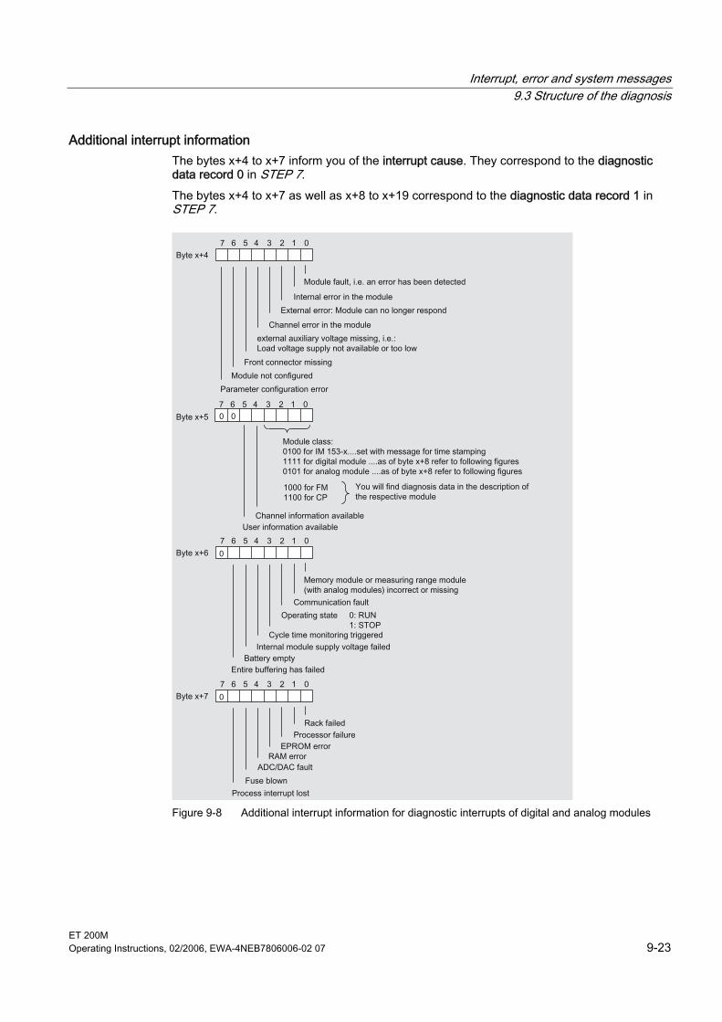
Interrupt, error and system messages 9.3 Structure of the diagnosis
ET 200M Operating Instructions, 02/2006, EWA-4NEB7806006-02 07 9-23
Additional interrupt information The bytes x+4 to x+7 inform you of the interrupt cause. They correspond to the diagnostic data record 0 in STEP 7. The bytes x+4 to x+7 as well as x+8 to x+19 correspond to the diagnostic data record 1 in STEP 7.
Figure 9-8 Additional interrupt information for diagnostic interrupts of digital and analog modules
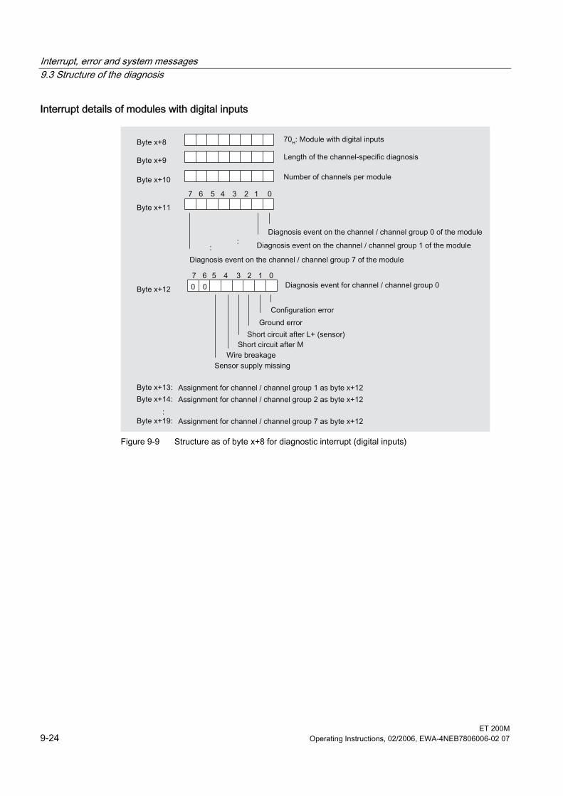
Interrupt, error and system messages 9.3 Structure of the diagnosis
ET 200M 9-24 Operating Instructions, 02/2006, EWA-4NEB7806006-02 07
Interrupt details of modules with digital inputs
Figure 9-9 Structure as of byte x+8 for diagnostic interrupt (digital inputs)
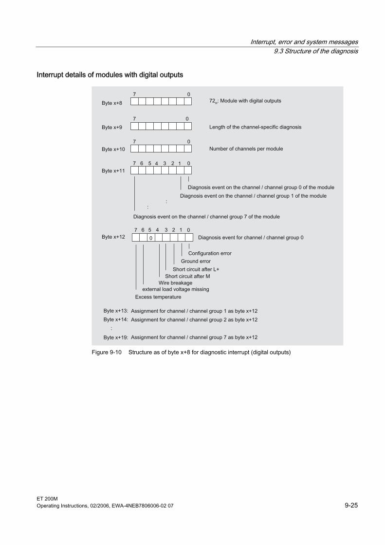
Interrupt, error and system messages 9.3 Structure of the diagnosis
ET 200M Operating Instructions, 02/2006, EWA-4NEB7806006-02 07 9-25
Interrupt details of modules with digital outputs
Figure 9-10 Structure as of byte x+8 for diagnostic interrupt (digital outputs)
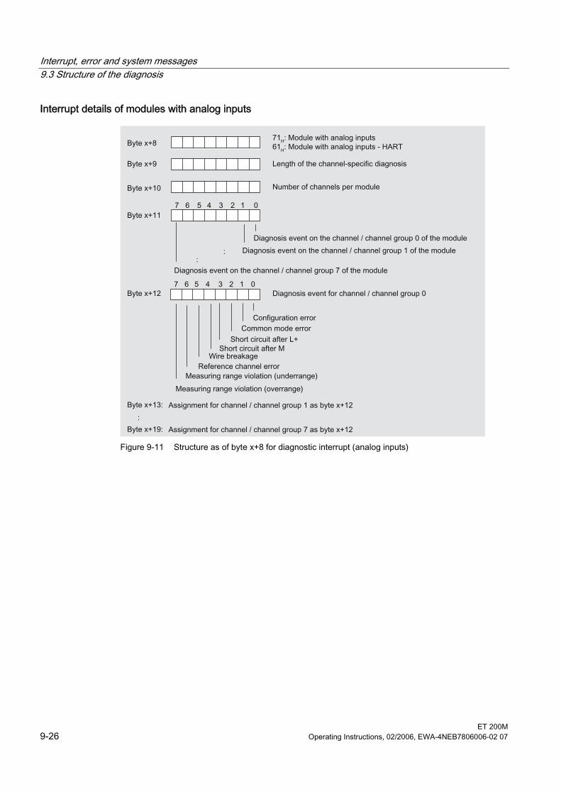
Interrupt, error and system messages 9.3 Structure of the diagnosis
ET 200M 9-26 Operating Instructions, 02/2006, EWA-4NEB7806006-02 07
Interrupt details of modules with analog inputs
Figure 9-11 Structure as of byte x+8 for diagnostic interrupt (analog inputs)
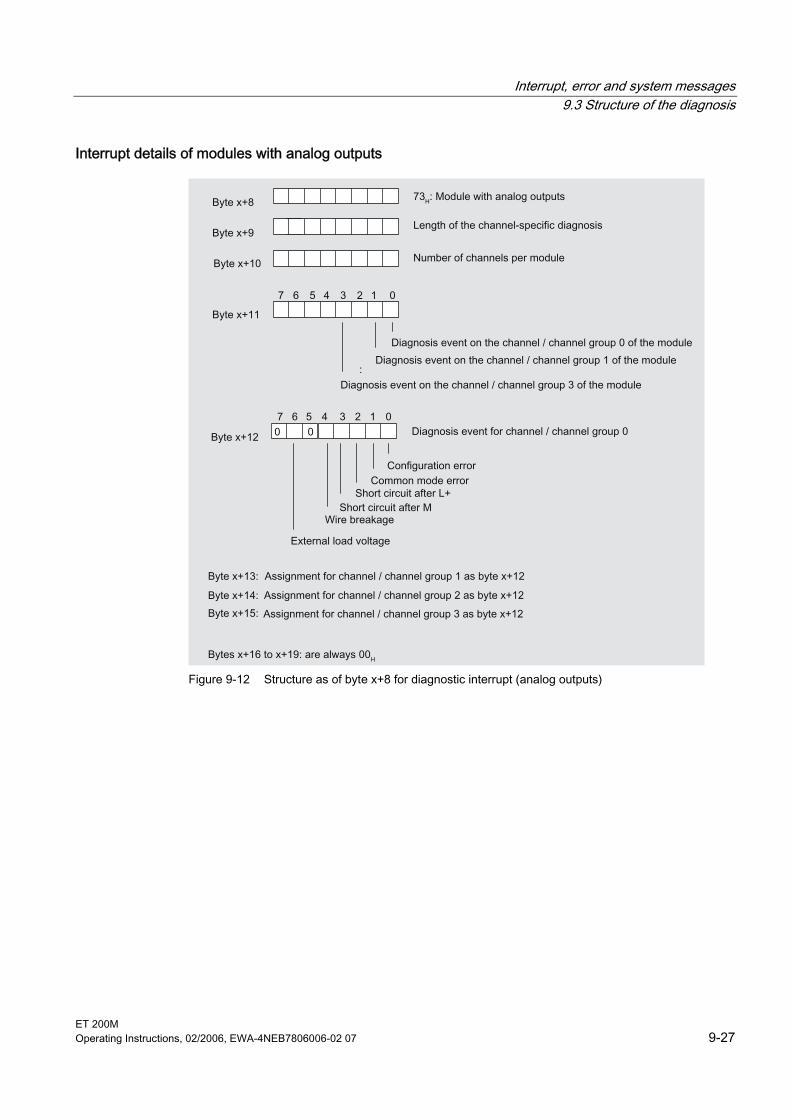
Interrupt, error and system messages 9.3 Structure of the diagnosis
ET 200M Operating Instructions, 02/2006, EWA-4NEB7806006-02 07 9-27
Interrupt details of modules with analog outputs
Figure 9-12 Structure as of byte x+8 for diagnostic interrupt (analog outputs)
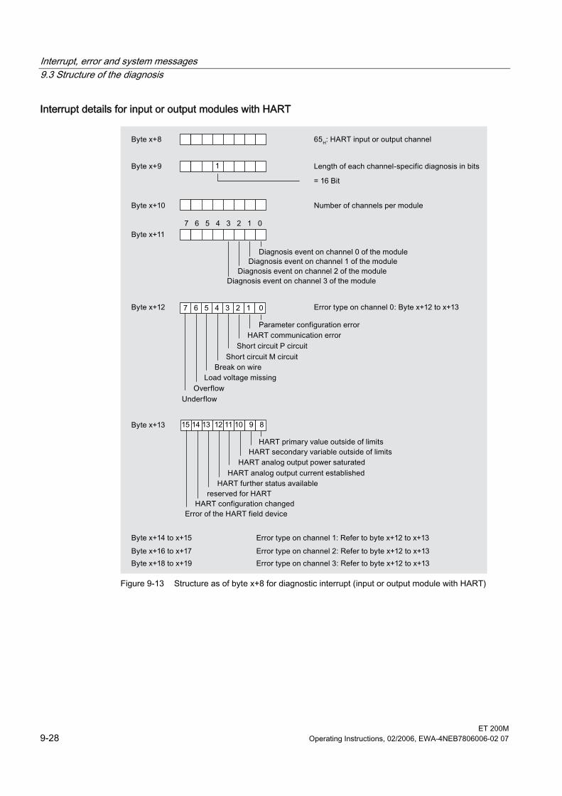
Interrupt, error and system messages 9.3 Structure of the diagnosis
ET 200M 9-28 Operating Instructions, 02/2006, EWA-4NEB7806006-02 07
Interrupt details for input or output modules with HART
Figure 9-13 Structure as of byte x+8 for diagnostic interrupt (input or output module with HART)
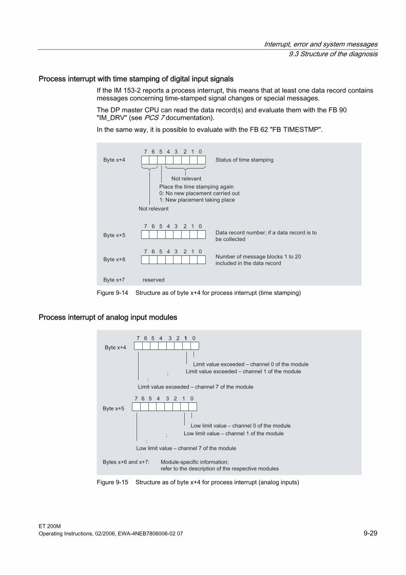
Interrupt, error and system messages 9.3 Structure of the diagnosis
ET 200M Operating Instructions, 02/2006, EWA-4NEB7806006-02 07 9-29
Process interrupt with time stamping of digital input signals If the IM 153-2 reports a process interrupt, this means that at least one data record contains messages concerning time-stamped signal changes or special messages. The DP master CPU can read the data record(s) and evaluate them with the FB 90 "IM_DRV" (see PCS 7 documentation). In the same way, it is possible to evaluate with the FB 62 "FB TIMESTMP".
Figure 9-14 Structure as of byte x+4 for process interrupt (time stamping)
Process interrupt of analog input modules
Figure 9-15 Structure as of byte x+4 for process interrupt (analog inputs)
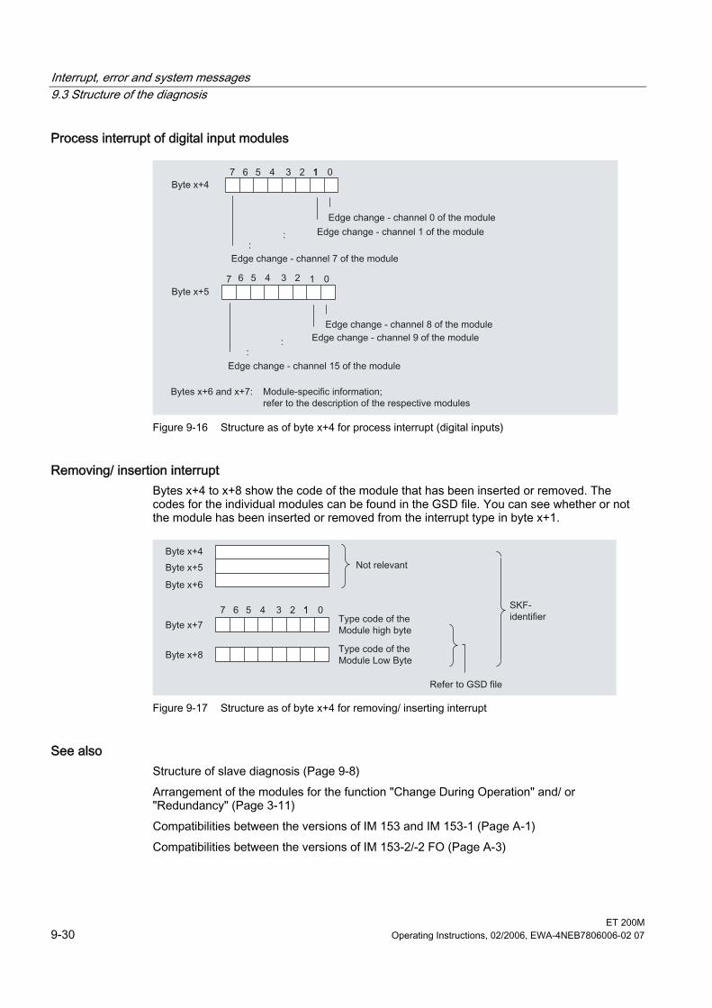
Interrupt, error and system messages 9.3 Structure of the diagnosis
ET 200M 9-30 Operating Instructions, 02/2006, EWA-4NEB7806006-02 07
Process interrupt of digital input modules
Figure 9-16 Structure as of byte x+4 for process interrupt (digital inputs)
Removing/ insertion interrupt Bytes x+4 to x+8 show the code of the module that has been inserted or removed. The codes for the individual modules can be found in the GSD file. You can see whether or not the module has been inserted or removed from the interrupt type in byte x+1.
Figure 9-17 Structure as of byte x+4 for removing/ inserting interrupt
See also Structure of slave diagnosis (Page 9-8) Arrangement of the modules for the function "Change During Operation" and/ or "Redundancy" (Page 3-11) Compatibilities between the versions of IM 153 and IM 153-1 (Page A-1) Compatibilities between the versions of IM 153-2/-2 FO (Page A-3)
Interrupt, error and system messages 9.3 Structure of the diagnosis
ET 200M Operating Instructions, 02/2006, EWA-4NEB7806006-02 07 9-31
9.3.11 Evaluating interrups from station diagnosis The structure of the station diagnosis is the same as the structure of the interrupt section.
Interrupts with S7/ M7 DP master or DPV1 master The ET 200M supports the following interrupts: • Diagnostic Interrupt • Process interrupt • Removing/ insertion interrupt These interrupts can be evaluated using an S7/ M7 DP master or DPV1 master. In the case of an interrupt interrupts OBs automatically run in the master CPU (see programming manual System software for S7-300/ S7-400, program draft).
Inserting/ removing interrupts with S7/ M7 DP master or DPV1 master If you use the ET 200M with "Change during Operation" on an S7/ M7 DP master or a DPV1 master, the system behaves as follows: • When removing a module the IM 153-x reports a removing interrupt on the DP master
which executes the OB 83. In the OB 83 you program the desired response to the removing event. With I/O access the OB 122 (I/O access error) is called in the DP master CPU.
• If you insert a module that corresponds to the configuration, the IM 153-x reports an inserting interrupt on the DP master (call OB 83 with respective diagnostic buffer entry) and configures the module in accordance with the saved configuration.
• If you insert a module in a non-configured slot, the ET 200M behaves as follows: – In S7 mode the IM 153-x does not report an inserting interrupt. – In DPV1 mode the IM 153-x reports an inserting interrupt.
• If you insert a different module than configured: – then the IM 153-x reports an inserting mode to the DP master (call OB 83 with
respective diagnostic buffer entry); but ignores this non-configured module. – The module diagnosis is stopped, and you can read out the slot in which the wrong
module is inserted. – the SF LED indicates the error.
Note If you insert or remove a dummy module DM 370, then no inserting or removing interrupt is triggered.
Interrupt, error and system messages 9.3 Structure of the diagnosis
ET 200M 9-32 Operating Instructions, 02/2006, EWA-4NEB7806006-02 07
Warning Faults when removing and inserting will be tolerated for up to 1 second. This means, that in such a case the output values will not change within the tolerance time.
Interrupts with a different DP master If the ET 200M is being operated with a different DP master, these interrupts will be shown as device-related diagnostics of the ET 200M. You must continue to process the respective diagnostic events in the user program of the DP master.
Saving the Diagnosis In dependence of byte x+1, transfer the contents of the device-specific diagnosis to a data block, as • The interrupts are updated cyclically. • the contents of the diagnosis as of byte x+3 are dependent upon whether S7 diagnosis or
process interrupt or removal or insertion interrupt has been reported.
Note In order to evaluate diagnostics and process interrupts via the device-specific diagnosis with a different DP master you must note: • the DP master should be able to save the diagnosis messages, i.e. the diagnosis
messages should be stored within the DP master in a ring buffer. If the DP master cannot save the diagnosis messages, e.g. then always only the last incoming diagnosis message will be saved.
• You must scan the relevant bits in the device-related diagnostic data in your user program at regular intervals.
• With an IM 308-C connection as a DP master you cannot use the process interrupts within the device-specific diagnosis, as only incoming - and not outgoing - interrupts can be reported. E.g. the bit "Upper limit exceeded" is then only reset when the bit "Lower limit exceeded" is set. End of cycle interrupts are not supported by the IM 308 C as end of cycle interrupts are updated to "1" with each end of cycle (the level of the signal does not change).
Inserting/ removing interrupts with other DP masters If you use the ET 200M with "Change during Operation" on a different DP master, you must note that this cannot evaluate the inserting and removing interrupts. You can evaluate the inserting or removing events in the code- and device-specific diagnosis of the IM 153-x. Tip: Evaluate the module status in the enhanced diagnosis.
See also Identifier-related diagnosis (Page 9-13) Interrupts (Page 9-21)
ET 200M Operating Instructions, 02/2006, EWA-4NEB7806006-02 07 10-1
Technical Specifications 10Technical Specifications
The technical specifications contain • standards and approvals valid for the ET 200M, • the technical data of the IM 153-x interface module, • the dimensioned drawing of the IM 153-x interface module and • the block diagram of the IM 153-x interface module.
Reference Manual You can find the following in the Module Specifications Reference Manual: • The technical specifications of the modules. • the general technical data like specifications for noise immunity of the modules as well as
mechanical and climatic ambient conditions. • the mechanical and climatic ambient conditions for SIPLUS S7-300 modules (for use in
other operating conditions "outdoors").
10.1 10.1 Standards and Approvals
CE Label The ET 200M distributed I/O device meets the requirements and protection objectives of the following EU directives and complies with the harmonized European standards (EN) that have been published for programmable controllers in the Official Journal of the European Communities: • 73/23/EEC Low Voltage Directive (for electrical equipment) • 89/336/EEC Electromagnetic Compatibility Directive (EMC Directive) • 94/9/EU "Devices and protection systems for use as prescribed in potentially explosive
areas" (Guidelines for Explosion Protection) The EC Declarations of Conformity are available to the relevant authorities at the following address: Siemens Aktiengesellschaft Bereich Automatisierungs- und Antriebstechnik A&D AS RD ST PLC Postfach 1963 D92209 Amberg
Technical Specifications 10.1 Standards and Approvals
ET 200M 10-2 Operating Instructions, 02/2006, EWA-4NEB7806006-02 07
UL Approval Underwriters Laboratories Inc. in accordance with • UL 508 (Industrial Control Equipment)
CSA Certification Canadian Standards Association to • C22.2 No. 142 (Process Control Equipment) or Underwriters Laboratories Inc. in accordance with • UL 508 (Industrial Control Equipment) • CSA C22.2 No. 142 (Process Control Equipment) or Underwriters Laboratories Inc. in accordance with • UL 508 (Industrial Control Equipment) • CSA C22.2 No. 142 (Process Control Equipment) • UL 1604 (Hazardous Location) • CSA-213 (Hazardous Location) APPROVED for use in Class I, Division 2, Group A, B, C, D Tx; Class I, Zone 2, Group IIC Tx
Note Currently valid certifications can be found on the rating of the relevant module.
FM certification Factory Mutual Research (FM) in accordance with Approval Standard Class Number 3611, 3600, 3810 APPROVED for use in Class I, Division 2, Group A, B, C, D Tx Class I, Zone 2, Group IIC Tx in accordance with EN 50021 (Electrical apparatus for potentially explosive atmospheres; Type of protection "n")
II 3 G EEx nA II T5
Technical Specifications 10.1 Standards and Approvals
ET 200M Operating Instructions, 02/2006, EWA-4NEB7806006-02 07 10-3
Tick-mark for Australia The ET 200M distributed I/O device meets the requirements of the standard AS/NZS 2064 (Class A).
IEC 61131 The ET 200M distributed I/O device meets the requirements and criteria of the IEC 611312 standard (programmable controllers, Part 2: Equipment Requirements and Tests.)
PROFIBUS standard The ET 200 distributed I/O system is based on standard IEC 61784-1:2002 Ed1 CP 3/1.
PNO PNO Certificate No.:
Interface module Certificate Number
IM 153-1 Z00577 IM 153-2 Z00289
IM 153-2 FO Z00289
Marine approvals Classification Societies: • ABS (American Bureau of Shipping) • BV (Bureau Veritas) • DNV (Det Norske Veritas) • GL (Germanischer Lloyd) • LRS (Lloyds Register of Shipping) • Class NK (Nippon Kaiji Kyokai)
Use in industry SIMATIC products are designed for industrial applications.
Table 10-1 Use in industry
Area of Application Requirements Emitted Interference Noise Immunity Industry EN 61000-6-4 : 2001 EN 61000-6-2 : 2001
Technical Specifications 10.1 Standards and Approvals
ET 200M 10-4 Operating Instructions, 02/2006, EWA-4NEB7806006-02 07
Use in residential areas If you use the ET 200M in residential areas, you must ensure that the radio interference emissions comply with limit value class B in accordance with EN 55011. The following measures are recommended to ensure the interference complies with limit value class B: • Install the ET 200M in grounded switching cabinets/boxes • Use of noise filters in the supply lines
Warning
There is a risk of injury or of damage to assets. In potentially explosive environments, there is a risk of injury or damage if you disconnect any connectors while the ET 200M is in operation. Always isolate the ET 200M is operated in such areas before you disconnect and connectors.
Laser protection classes authorization (for the IM 153-2 FO) Class 1 in accordance with EN 60825-1: 1994+A11: 1996 or IEC 60825-1: 1993 including amendment 1:1997 In the case of an intentional/ unintentional opening of the accessible FOC radiation in accordance with degree of endangering 1 as per EN 60825-2: 1994 or IEC 60825-2: 1993.
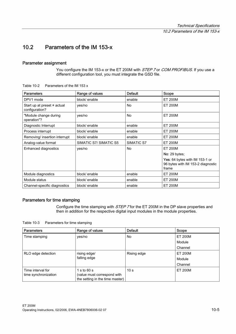
Technical Specifications 10.2 Parameters of the IM 153-x
ET 200M Operating Instructions, 02/2006, EWA-4NEB7806006-02 07 10-5
10.2 10.2 Parameters of the IM 153-x
Parameter assignment You configure the IM 153-x or the ET 200M with STEP 7 or COM PROFIBUS. If you use a different configuration tool, you must integrate the GSD file.
Table 10-2 Parameters of the IM 153 x
Parameters Range of values Default Scope DPV1 mode block/ enable enable ET 200M Start up at preset ≠ actual configuration?
yes/no No ET 200M
"Module change during operation"?
yes/no No ET 200M
Diagnostic Interrupt block/ enable enable ET 200M Process interrupt block/ enable enable ET 200M Removing/ insertion interrupt block/ enable enable ET 200M Analog-value format SIMATIC S7/ SIMATIC S5 SIMATIC S7 ET 200M Enhanced diagnostics yes/no No ET 200M
No: 29 bytes; Yes: 64 bytes with IM 153-1 or 96 bytes with IM 153-2 diagnostic frame
Module diagnostics block/ enable enable ET 200M Module status block/ enable enable ET 200M Channel-specific diagnostics block/ enable enable ET 200M
Parameters for time stamping Configure the time stamping with STEP 7 for the ET 200M in the DP slave properties and then in addition for the respective digital input modules in the module properties.
Table 10-3 Parameters for time stamping
Parameters Range of values Default Scope Time stamping yes/no No ET 200M
Module Channel
RLO edge detection rising edge/ falling edge
Rising edge ET 200M Module Channel
Time interval for time synchronization
1 s to 60 s (value must correspond with the setting in the time master)
10 s ET 200M
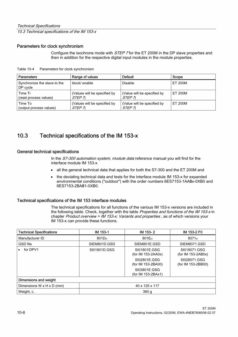
Technical Specifications 10.3 Technical specifications of the IM 153-x
ET 200M 10-6 Operating Instructions, 02/2006, EWA-4NEB7806006-02 07
Parameters for clock synchronism Configure the isochrone mode with STEP 7 for the ET 200M in the DP slave properties and then in addition for the respective digital input modules in the module properties.
Table 10-4 Parameters for clock synchronism
Parameters Range of values Default Scope Synchronize the slave to the DP cycle
block/ enable Disable ET 200M
Time Ti (read process values)
(Values will be specified by STEP 7)
(Value will be specified by STEP 7)
ET 200M
Time To (output process values)
(Values will be specified by STEP 7)
(Value will be specified by STEP 7)
ET 200M
10.3 10.3 Technical specifications of the IM 153-x
General technical specifications In the S7-300 automation system, module data reference manual you will find for the interface module IM 153-x • all the general technical data that applies for both the S7-300 and the ET 200M and • the deviating technical data and tests for the interface module IM 153-x for expanded
environmental conditions ("outdoor") with the order numbers 6ES7153-1AA8x-0XB0 and 6ES7153-2BA81-0XB0.
Technical specifications of the IM 153 interface modules The technical specifications for all functions of the various IM 153-x versions are included in the following table. Check, together with the table Properties and functions of the IM 153-x in chapter Product overview > IM 153-x: Variants and properties , as of which versions your IM 153-x can provide these functions.
Technical Specifications IM 153-1 IM 153- 2 IM 153-2 F0 Manufacturer ID 801DH 801EH 8071H GSD file SIEM801D.GSD SIEM801E.GSD SIEM8071.GSD • for DPV1 SI01801D.GSG SI01801E.GSG
(for IM 153-2AA0x) SI02801E.GSG
(for IM 153-2BA00) SI03801E.GSG
(for IM 153-2BAx1)
SI018071.GSG (for IM 153-2AB0x)
SI028071.GSG (for IM 153-2BB00)
Dimensions and weight Dimensions W x H x D (mm) 40 x 125 x 117 Weight, c. 360 g
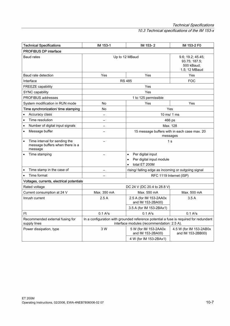
Technical Specifications 10.3 Technical specifications of the IM 153-x
ET 200M Operating Instructions, 02/2006, EWA-4NEB7806006-02 07 10-7
Technical Specifications IM 153-1 IM 153- 2 IM 153-2 F0 PROFIBUS DP interface Baud rates Up to 12 MBaud 9.6; 19.2; 45.45;
93.75; 187.5; 500 kBaud;
1.5; 12 MBaud Baud rate detection Yes Yes Yes Interface RS 485 FOC FREEZE capability Yes SYNC capability Yes PROFIBUS addresses 1 to 125 permissible System modification in RUN mode No Yes Yes Time synchronization/ time stamping No Yes • Accuracy class – 10 ms/ 1 ms • Time resolution – 466 ps • Number of digital input signals – Max. 128 • Message buffer – 15 message buffers with in each case max. 20
messages • Time interval for sending the
message buffers when there is a message
– 1 s
• Time stamping – • Per digital input • Per digital input module • total ET 200M
• Time stamp in the case of – rising/ falling edge as incoming or outgoing signal • Time format – RFC 1119 Internet (ISP) Voltages, currents, electrical potentials Rated voltage DC 24 V (DC 20.4 to 28.8 V) Current consumption at 24 V Max. 350 mA Max. 550 mA Max. 500 mA
2.5 A (for IM 153-2AA0x and IM 153-2BA00)
Inrush current 2.5 A
3.5 A (for IM 153-2BAx1)
3.5 A
I2t 0.1 A2s 0.1 A2s 0.1 A2s Recommended external fusing for supply lines
In a configuration with grounded reference potential a fuse is required for redundant interface modules (recommendation: 2.5 A).
5 W (for IM 153-2AA0x and IM 153-2BA00)
Power dissipation, type 3 W
4 W (for IM 153-2BAx1)
4.5 W (for IM 153-2AB0x and IM 153-2BB00)
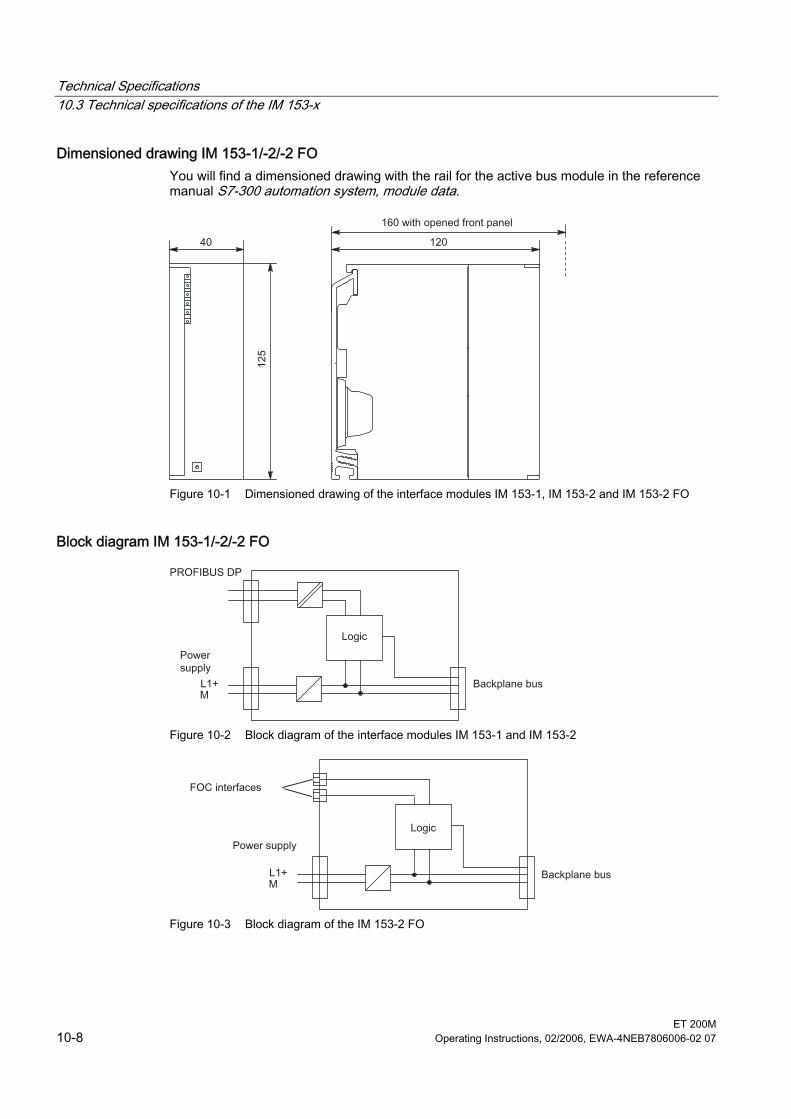
Technical Specifications 10.3 Technical specifications of the IM 153-x
ET 200M 10-8 Operating Instructions, 02/2006, EWA-4NEB7806006-02 07
Dimensioned drawing IM 153-1/-2/-2 FO You will find a dimensioned drawing with the rail for the active bus module in the reference manual S7-300 automation system, module data.
Figure 10-1 Dimensioned drawing of the interface modules IM 153-1, IM 153-2 and IM 153-2 FO
Block diagram IM 153-1/-2/-2 FO
Figure 10-2 Block diagram of the interface modules IM 153-1 and IM 153-2
Figure 10-3 Block diagram of the IM 153-2 FO
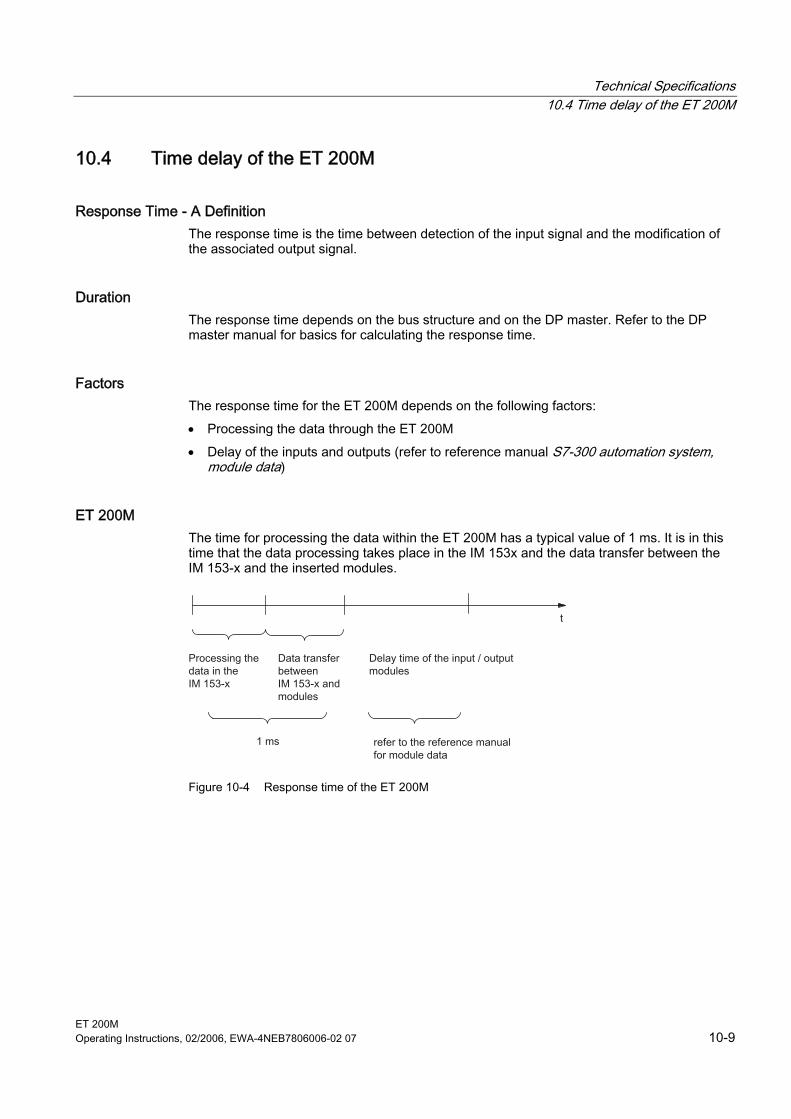
Technical Specifications 10.4 Time delay of the ET 200M
ET 200M Operating Instructions, 02/2006, EWA-4NEB7806006-02 07 10-9
10.4 10.4 Time delay of the ET 200M
Response Time - A Definition The response time is the time between detection of the input signal and the modification of the associated output signal.
Duration The response time depends on the bus structure and on the DP master. Refer to the DP master manual for basics for calculating the response time.
Factors The response time for the ET 200M depends on the following factors: • Processing the data through the ET 200M • Delay of the inputs and outputs (refer to reference manual S7-300 automation system,
module data)
ET 200M The time for processing the data within the ET 200M has a typical value of 1 ms. It is in this time that the data processing takes place in the IM 153x and the data transfer between the IM 153-x and the inserted modules.
Figure 10-4 Response time of the ET 200M
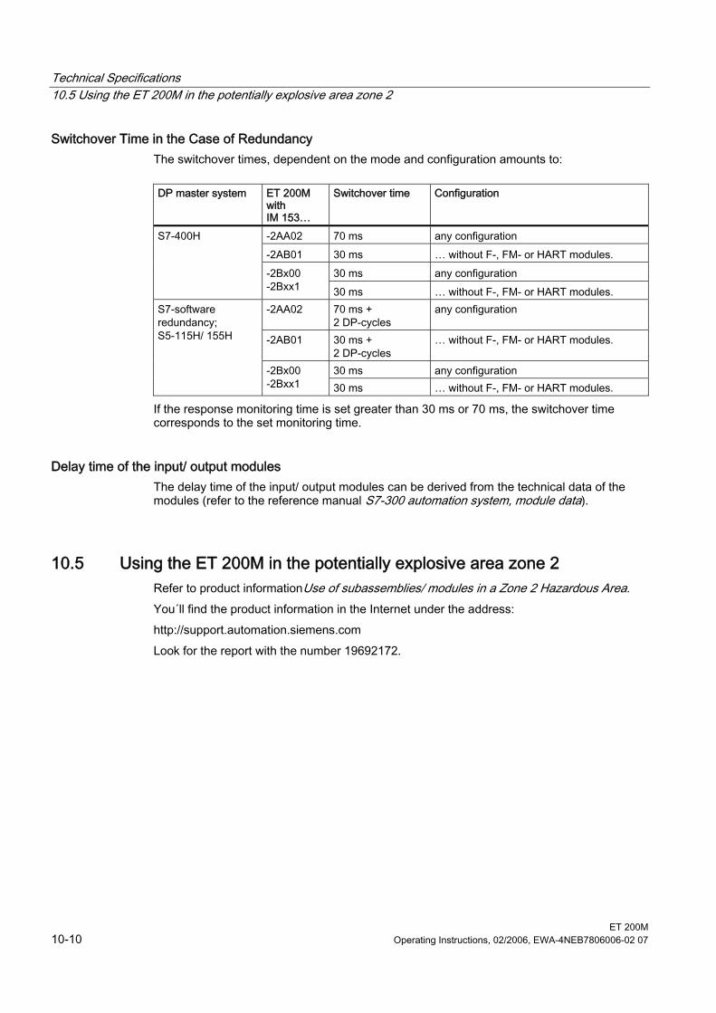
Technical Specifications 10.5 Using the ET 200M in the potentially explosive area zone 2
ET 200M 10-10 Operating Instructions, 02/2006, EWA-4NEB7806006-02 07
Switchover Time in the Case of Redundancy The switchover times, dependent on the mode and configuration amounts to:
DP master system ET 200M
with IM 153…
Switchover time Configuration
-2AA02 70 ms any configuration -2AB01 30 ms … without F-, FM- or HART modules.
30 ms any configuration
S7-400H
-2Bx00 -2Bxx1 30 ms … without F-, FM- or HART modules. -2AA02 70 ms +
2 DP-cycles any configuration
-2AB01 30 ms + 2 DP-cycles
… without F-, FM- or HART modules.
30 ms any configuration
S7-software redundancy; S5-115H/ 155H
-2Bx00 -2Bxx1 30 ms … without F-, FM- or HART modules.
If the response monitoring time is set greater than 30 ms or 70 ms, the switchover time corresponds to the set monitoring time.
Delay time of the input/ output modules The delay time of the input/ output modules can be derived from the technical data of the modules (refer to the reference manual S7-300 automation system, module data).
10.5 10.5 Using the ET 200M in the potentially explosive area zone 2 Refer to product informationUse of subassemblies/ modules in a Zone 2 Hazardous Area. You´ll find the product information in the Internet under the address: http://support.automation.siemens.com Look for the report with the number 19692172.
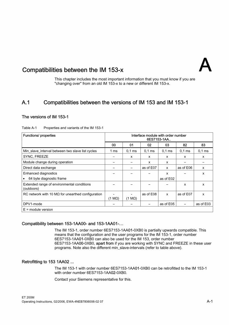
ET 200M Operating Instructions, 02/2006, EWA-4NEB7806006-02 07 A-1
A Compatibilities between the IM 153-x AThis chapter includes the most important information that you must know if you are "changing over" from an old IM 153-x to a new or different IM 153-x.
A.1 A.1 Compatibilities between the versions of IM 153 and IM 153-1
The versions of IM 153-1
Table A-1 Properties and variants of the IM 153-1
Interface module with order number 6ES7153-1AA..
Functions/ properties
00 01 02 03 82 83 Min_slave_interval between two slave list cycles 1 ms 0,1 ms 0,1 ms 0,1 ms 0,1 ms 0,1 ms SYNC, FREEZE – x x x x x Module change during operation – – x x – – Direct data exchange – – as of E07 x as of E06 x Enhanced diagnostics • 64 byte diagnostic frame
– – – x as of E02
– x
Extended range of environmental conditions (outdoors)
– – – – x x
RC network with 10 MΩ for unearthed configuration - (1 MΩ)
- (1 MΩ)
as of E08 x as of E07 x
DPV1-mode – – – as of E05 – as of E03 E = module version
Compatibility between 153-1AA00- and 153-1AA01-… The IM 153-1, order number 6ES7153-1AA01-0XB0 is partially upwards compatible. This means that the configuration and the user programs for the IM 153-1, order number 6ES7153-1AA01-0XB0 can also be used for the IM 153, order number 6ES7153-1AA00-0XB0, apart from if you are working with SYNC and FREEZE in these user programs. Note also the different min_slave-intervals (refer to table above).
Retrofitting to 153 1AA02 ... The IM 153-1 with order number 6ES7153-1AA01-0XB0 can be retrofitted to the IM 153-1 with order number 6ES7153-1AA02-0XB0. Contact your Siemens representative for this.
Compatibilities between the IM 153-x A.1 Compatibilities between the versions of IM 153 and IM 153-1
ET 200M A-2 Operating Instructions, 02/2006, EWA-4NEB7806006-02 07
Behavior with inserting/ removing interrupt
up to 153-1AA03, module version 01
as of 153-1AA03, module version 02
The ET 200M is set up on active bus modules. The removal/insertion interrupt is disabled at parameter assignment. The removal or insertion of a module results in station failure.
The ET 200M is set up on active bus modules. The removal/insertion interrupt is disabled at parameter assignment. It is still, however, possible to remove and insert modules. An interrupt is not reported, but the events are displayed in the diagnosis.
Startup Characteristics When Response Monitoring is Switched Off The IM 153-1 as of 6ES7153-1AA02-0XB0, module version 05 has a different behavior when the DP normal master is restarted with a switched off response monitoring: If the response monitoring is switched off, in the event of a DP master failure the outputs of the ET 200M maintain their set values. When the DP master starts again without resetting the DP slave these output values remain until the new output data is received from the DP master. Without resetting the DP slave means that the DP slave is not enabled for other DP masters. In the parameter assignment message frame, the bit 6 of the "Octet 1: station_status, unlock_req" has the value "0" (e.g. with the DP master of the SIMATIC 505). In the case of previous versions: When restarting the DP master, the outputs of the ET 200M are briefly set to "0" until they are reset by the DP master. If the response monitoring switched on is set, the IM 153-1AA02 as of E05 behaves like the predecessor versions.
Configuration of the IM 153-1 with the general ID format (AKF) You can also configure the IM 153-1 as of order number 6ES7153-1AA03-0XB0, module version 02, with the general ID format AKF. This configuration assumes detailed knowledge of the structure of the AKF. You must use the code 0x00 for the slots 1 to 3.
Warning If you conduct the configuration with the general ID format AKF, the quality of the comparison of the preset and actual configuration when the DP slave starts up or when removing or inserting modules is very low. Since there is no type ID available for the comparison, an incorrect configuration cannot be easily detected!
See also Configuration of an ET 200M with ungrounded reference potential (Page 3-21) RC Network with 1 MΩ for Configuration with ungrounded reference potential (Page A-6)
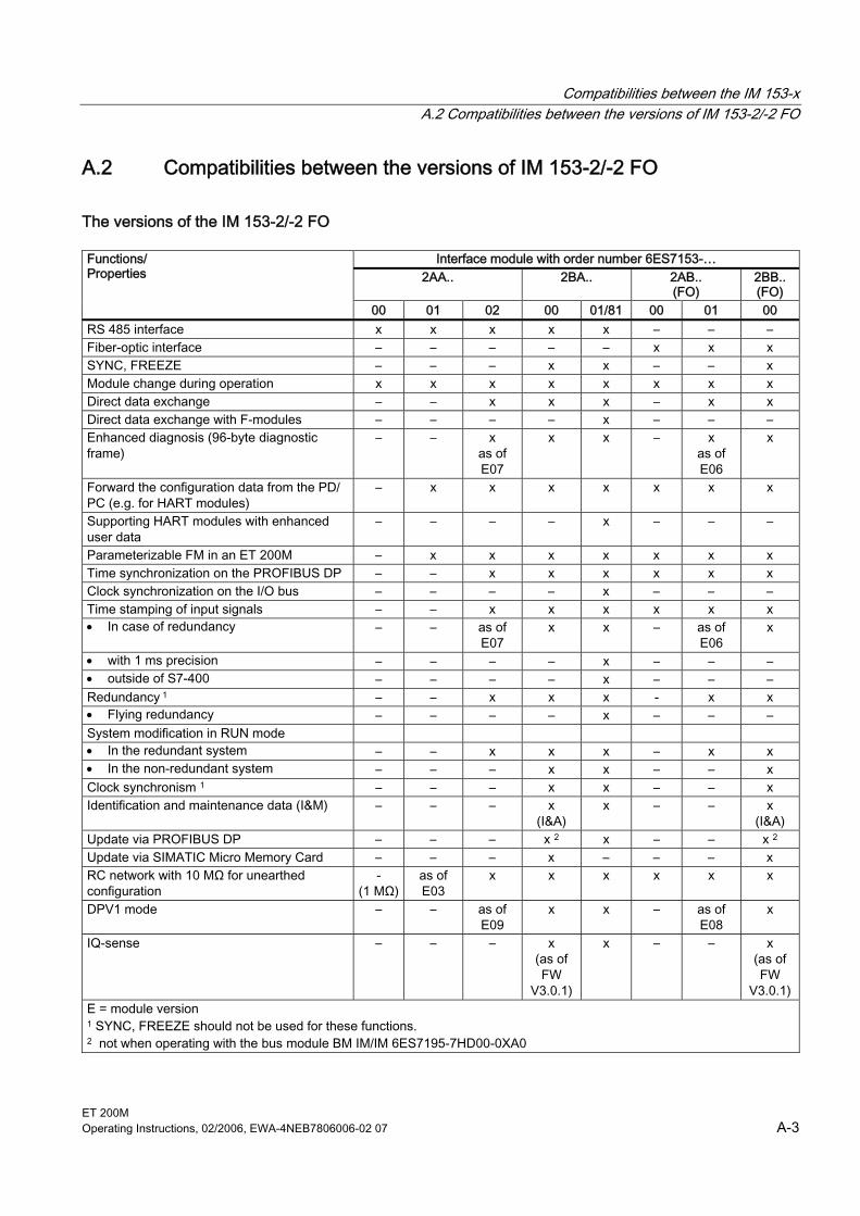
Compatibilities between the IM 153-x A.2 Compatibilities between the versions of IM 153-2/-2 FO
ET 200M Operating Instructions, 02/2006, EWA-4NEB7806006-02 07 A-3
A.2 A.2 Compatibilities between the versions of IM 153-2/-2 FO
The versions of the IM 153-2/-2 FO
Interface module with order number 6ES7153-… 2AA.. 2BA.. 2AB..
(FO) 2BB.. (FO)
Functions/ Properties
00 01 02 00 01/81 00 01 00 RS 485 interface x x x x x – – – Fiber-optic interface – – – – – x x x SYNC, FREEZE – – – x x – – x Module change during operation x x x x x x x x Direct data exchange – – x x x – x x Direct data exchange with F-modules – – – – x – – – Enhanced diagnosis (96-byte diagnostic frame)
– – x as of E07
x x – x as of E06
x
Forward the configuration data from the PD/ PC (e.g. for HART modules)
– x x x x x x x
Supporting HART modules with enhanced user data
– – – – x – – –
Parameterizable FM in an ET 200M – x x x x x x x Time synchronization on the PROFIBUS DP – – x x x x x x Clock synchronization on the I/O bus – – – – x – – – Time stamping of input signals – – x x x x x x • In case of redundancy – – as of
E07 x x – as of
E06 x
• with 1 ms precision – – – – x – – – • outside of S7-400 – – – – x – – – Redundancy 1 – – x x x - x x • Flying redundancy – – – – x – – – System modification in RUN mode • In the redundant system – – x x x – x x • In the non-redundant system – – – x x – – x Clock synchronism 1 – – – x x – – x Identification and maintenance data (I&M) – – – x
(I&A) x – – x
(I&A) Update via PROFIBUS DP – – – x 2 x – – x 2 Update via SIMATIC Micro Memory Card – – – x – – – x RC network with 10 MΩ for unearthed configuration
- (1 MΩ)
as of E03
x x x x x x
DPV1 mode – – as of E09
x x – as of E08
x
IQ-sense – – – x (as of FW
V3.0.1)
x – – x (as of FW
V3.0.1) E = module version 1 SYNC, FREEZE should not be used for these functions. 2 not when operating with the bus module BM IM/IM 6ES7195-7HD00-0XA0
Compatibilities between the IM 153-x A.2 Compatibilities between the versions of IM 153-2/-2 FO
ET 200M A-4 Operating Instructions, 02/2006, EWA-4NEB7806006-02 07
Retrofitting You can retrofit the IM 153-2 with order number 6ES7153-2AA02-0XB0; module version 06 to the module version 07 - this is subject to a fee. You can retrofit the IM 153-2 FO with order number 6ES7153-2AB01-0XB0, module version 05 to module version 06 - this is subject to a fee. Contact your Siemens representative for this.
Behavior with inserting/ removing interrupt
up to 153-2AA02, module version 06 153-2AB01, module version 05
as of 153-2AA02, module version 07 153-2AB01, module version 06
The ET 200M is set up on active bus modules. The removal/insertion interrupt is disabled at parameter assignment. The removal or insertion of a module results in station failure.
The ET 200M is set up on active bus modules. The removal/insertion interrupt is disabled at parameter assignment. It is still, however, possible to remove and insert modules. An interrupt is not reported, but the events are displayed in the diagnosis.
Configurable FM in a configuration with IM 153-2 For the distributed use of the FM 353/ 354/ 355 with full S7 functionality you can use the following CPUs and FMs only as of the specified order numbers and module versions. CPUs and FMs not listed in the table (e.g. CPU 316-2 DP) can be used as of the respective first module version.
Table A-2 Restrictions for DP master CPUs and FM for IM 153-2
Module as of order no. ... with module version Operating system update is possible as of version module
CPU 315-2 DP 6ES7315-2AF01-0AB0 03 01 CPU 413-2 DP 6ES7413-2XG01-0AB0 02 01 CPU 414-2 DP 6ES7414-2XG01-0AB0
6ES7414-2XJ00-0AB0 02 04
01 03
CPU 416-2 DP 6ES7416-2XK00-0AB0 6ES7416-2XL00-0AB0
04 04
03 03
FM 353 FM 354 FM 355C FM 355S
6ES7353-1AH01-0AE0 6ES7354-1AH01-0AE0 6ES7355-0VH10-0AE0 6ES7355-1VH10-0AE0
01 01 01 01
– – – –
Compatibilities between the IM 153-x A.2 Compatibilities between the versions of IM 153-2/-2 FO
ET 200M Operating Instructions, 02/2006, EWA-4NEB7806006-02 07 A-5
Configuration of the IM 153-2 with the general ID format (AKF) You can also configure the IM 153-2 as of order number 6ES7153-2AA02-0XB0, module version 07, and 6ES7153-2AB01-0XB0, module version 06, with the general ID format AKF. This configuration assumes detailed knowledge of the structure of the AKF. You must use the code 0x00 for the slots 1 to 3.
Warning If you conduct the configuration with the general ID format AKF, the quality of the comparison of the preset and actual configuration when the DP slave starts up or when removing or inserting modules is very low. Since there is no type ID available for the comparison, an incorrect configuration cannot be easily detected!
Functionality of the Previous Version If you insert the IM 153-2Bx00 interface module • on a bus module BM IM/IM (6ES7195-7HD00-0XA0), • configure as an IM 153-2AA02/-2AB01 with STEP 7, • configure with GSD revision 2, then it has the functionality of an IM 153-2AA02/-2AB01.
See also Configuration of an ET 200M with ungrounded reference potential (Page 3-21) RC Network with 1 MΩ for Configuration with ungrounded reference potential (Page A-6) Redundancy with IM 153-2 (Page 8-30) What is Isochronous? (Page 8-36)
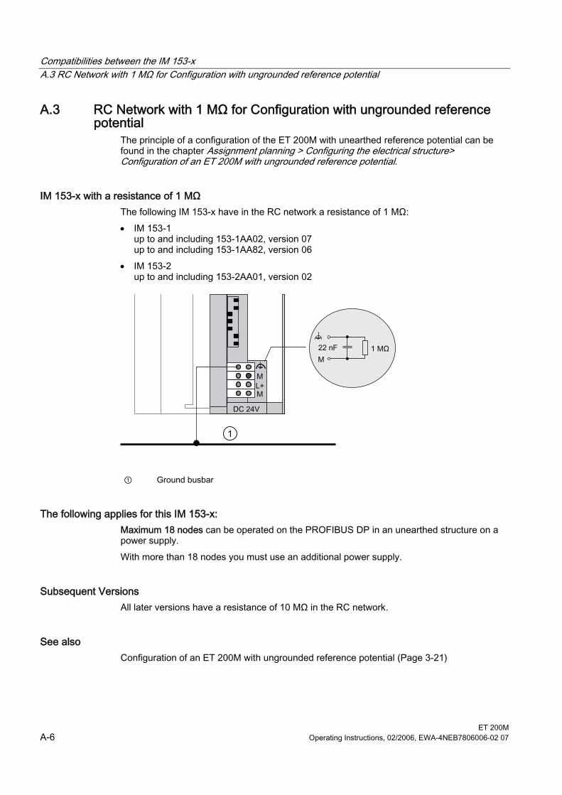
Compatibilities between the IM 153-x A.3 RC Network with 1 MΩ for Configuration with ungrounded reference potential
ET 200M A-6 Operating Instructions, 02/2006, EWA-4NEB7806006-02 07
A.3 A.3 RC Network with 1 MΩ for Configuration with ungrounded reference potential
The principle of a configuration of the ET 200M with unearthed reference potential can be found in the chapter Assignment planning > Configuring the electrical structure> Configuration of an ET 200M with ungrounded reference potential.
IM 153-x with a resistance of 1 MΩ The following IM 153-x have in the RC network a resistance of 1 MΩ: • IM 153-1
up to and including 153-1AA02, version 07 up to and including 153-1AA82, version 06
• IM 153-2 up to and including 153-2AA01, version 02
1
① Ground busbar
The following applies for this IM 153-x: Maximum 18 nodes can be operated on the PROFIBUS DP in an unearthed structure on a power supply. With more than 18 nodes you must use an additional power supply.
Subsequent Versions All later versions have a resistance of 10 MΩ in the RC network.
See also Configuration of an ET 200M with ungrounded reference potential (Page 3-21)
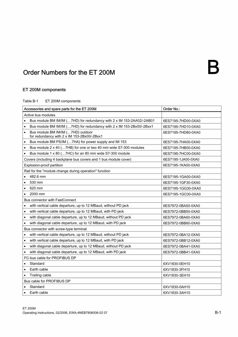
ET 200M Operating Instructions, 02/2006, EWA-4NEB7806006-02 07 B-1
B Order Numbers for the ET 200M BET 200M components
Table B-1 ET 200M components
Accessories and spare parts for the ET 200M Order No.: Active bus modules • Bus module BM IM/IM (…7HD) for redundancy with 2 x IM 153-2AA02/-2AB01 6ES7195-7HD00-0XA0 • Bus module BM IM/IM (…7HD) for redundancy with 2 x IM 153-2Bx00/-2Bxx1 6ES7195-7HD10-0XA0 • Bus module BM IM/IM (…7HD) outdoor
for redundancy with 2 x IM 153-2Bx00/-2Bxx1 6ES7195-7HD80-0XA0
• Bus module BM PS/IM (…7HA) for power supply and IM 153 6ES7195-7HA00-0XA0 • Bus module 2 x 40 (…7HB) for one or two 40 mm wide S7-300 modules 6ES7195-7HB00-0XA0 • Bus module 1 x 80 (…7HC) for an 80 mm wide S7-300 module 6ES7195-7HC00-0XA0 Covers (including 4 backplane bus covers and 1 bus module cover) 6ES7195-1JA00-0XA0 Explosion-proof partition 6ES7195-1KA00-0XA0 Rail for the "module change during operation" function • 482.6 mm 6ES7195-1GA00-0XA0 • 530 mm 6ES7195-1GF30-0XA0 • 620 mm 6ES7195-1GG30-0XA0 • 2000 mm 6ES7195-1GC00-0XA0 Bus connector with FastConnect • with vertical cable departure, up to 12 MBaud, without PD jack 6ES7972-0BA50-0XA0 • with vertical cable departure, up to 12 MBaud, with PD jack 6ES7972-0BB50-0XA0 • with diagonal cable departure, up to 12 MBaud, without PD jack 6ES7972-0BA60-0XA0 • with diagonal cable departure, up to 12 MBaud, with PD jack 6ES7972-0BB60-0XA0 Bus connector with screw-type terminal • with vertical cable departure, up to 12 MBaud, without PD jack 6ES7972-0BA12-0XA0 • with vertical cable departure, up to 12 MBaud, with PD jack 6ES7972-0BB12-0XA0 • with diagonal cable departure, up to 12 MBaud, without PD jack 6ES7972-0BA41-0XA0 • with diagonal cable departure, up to 12 MBaud, with PD jack 6ES7972-0BB41-0XA0 FC-bus cable for PROFIBUS DP • Standard 6XV1830-0EH10 • Earth cable 6XV1830-3FH10 • Trailing cable 6XV1830-3EH10 Bus cable for PROFIBUS DP • Standard 6XV1830-0AH10 • Earth cable 6XV1830-3AH10
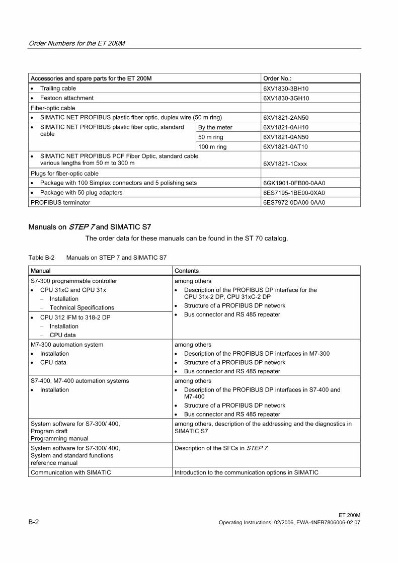
Order Numbers for the ET 200M
ET 200M B-2 Operating Instructions, 02/2006, EWA-4NEB7806006-02 07
Accessories and spare parts for the ET 200M Order No.: • Trailing cable 6XV1830-3BH10 • Festoon attachment 6XV1830-3GH10 Fiber-optic cable • SIMATIC NET PROFIBUS plastic fiber optic, duplex wire (50 m ring) 6XV1821-2AN50
By the meter 6XV1821-0AH10 50 m ring 6XV1821-0AN50
• SIMATIC NET PROFIBUS plastic fiber optic, standard cable
100 m ring 6XV1821-0AT10 • SIMATIC NET PROFIBUS PCF Fiber Optic, standard cable
various lengths from 50 m to 300 m 6XV1821-1Cxxx
Plugs for fiber-optic cable • Package with 100 Simplex connectors and 5 polishing sets 6GK1901-0FB00-0AA0 • Package with 50 plug adapters 6ES7195-1BE00-0XA0 PROFIBUS terminator 6ES7972-0DA00-0AA0
Manuals on STEP 7 and SIMATIC S7 The order data for these manuals can be found in the ST 70 catalog.
Table B-2 Manuals on STEP 7 and SIMATIC S7
Manual Contents S7-300 programmable controller • CPU 31xC and CPU 31x
– Installation – Technical Specifications
• CPU 312 IFM to 318-2 DP – Installation – CPU data
among others • Description of the PROFIBUS DP interface for the
CPU 31x-2 DP, CPU 31xC-2 DP • Structure of a PROFIBUS DP network • Bus connector and RS 485 repeater
M7-300 automation system • Installation • CPU data
among others • Description of the PROFIBUS DP interfaces in M7-300 • Structure of a PROFIBUS DP network • Bus connector and RS 485 repeater
S7-400, M7-400 automation systems • Installation
among others • Description of the PROFIBUS DP interfaces in S7-400 and
M7-400 • Structure of a PROFIBUS DP network • Bus connector and RS 485 repeater
System software for S7-300/ 400, Program draft Programming manual
among others, description of the addressing and the diagnostics in SIMATIC S7
System software for S7-300/ 400, System and standard functions reference manual
Description of the SFCs in STEP 7
Communication with SIMATIC Introduction to the communication options in SIMATIC
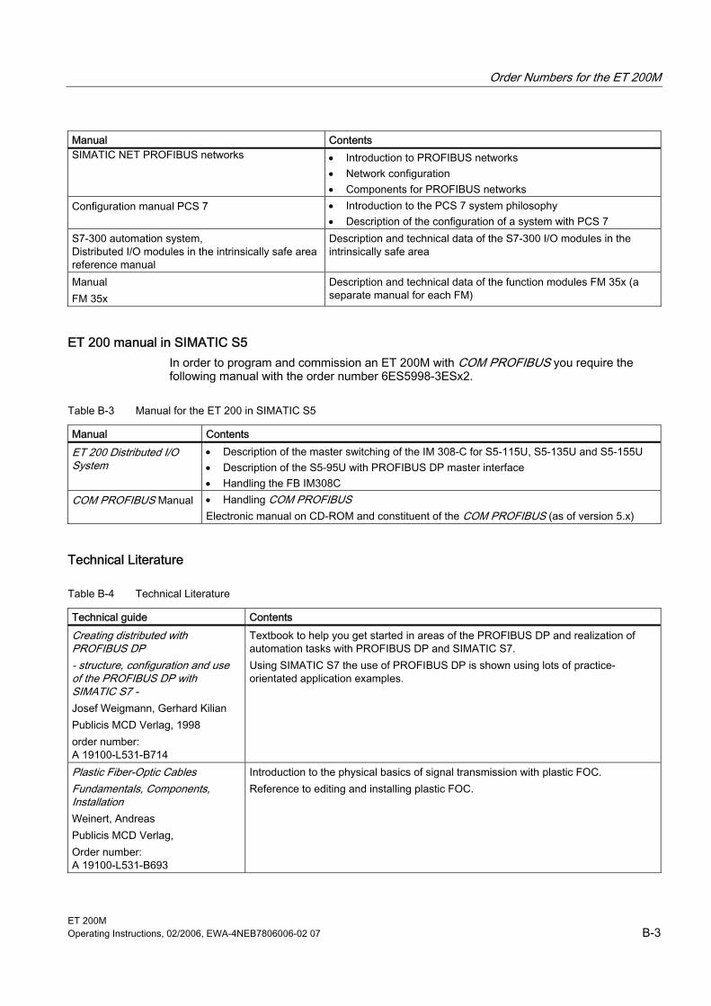
Order Numbers for the ET 200M
ET 200M Operating Instructions, 02/2006, EWA-4NEB7806006-02 07 B-3
Manual Contents SIMATIC NET PROFIBUS networks • Introduction to PROFIBUS networks
• Network configuration • Components for PROFIBUS networks
Configuration manual PCS 7 • Introduction to the PCS 7 system philosophy • Description of the configuration of a system with PCS 7
S7-300 automation system, Distributed I/O modules in the intrinsically safe areareference manual
Description and technical data of the S7-300 I/O modules in the intrinsically safe area
Manual FM 35x
Description and technical data of the function modules FM 35x (a separate manual for each FM)
ET 200 manual in SIMATIC S5 In order to program and commission an ET 200M with COM PROFIBUS you require the following manual with the order number 6ES5998-3ESx2.
Table B-3 Manual for the ET 200 in SIMATIC S5
Manual Contents ET 200 Distributed I/O System
• Description of the master switching of the IM 308-C for S5-115U, S5-135U and S5-155U • Description of the S5-95U with PROFIBUS DP master interface • Handling the FB IM308C
COM PROFIBUS Manual • Handling COM PROFIBUS Electronic manual on CD-ROM and constituent of the COM PROFIBUS (as of version 5.x)
Technical Literature
Table B-4 Technical Literature
Technical guide Contents Creating distributed with PROFIBUS DP - structure, configuration and use of the PROFIBUS DP with SIMATIC S7 - Josef Weigmann, Gerhard Kilian Publicis MCD Verlag, 1998 order number: A 19100-L531-B714
Textbook to help you get started in areas of the PROFIBUS DP and realization of automation tasks with PROFIBUS DP and SIMATIC S7. Using SIMATIC S7 the use of PROFIBUS DP is shown using lots of practice-orientated application examples.
Plastic Fiber-Optic Cables Fundamentals, Components, Installation Weinert, Andreas Publicis MCD Verlag, Order number: A 19100-L531-B693
Introduction to the physical basics of signal transmission with plastic FOC. Reference to editing and installing plastic FOC.

Order Numbers for the ET 200M
ET 200M B-4 Operating Instructions, 02/2006, EWA-4NEB7806006-02 07
ET 200M Operating Instructions, 02/2006, EWA-4NEB7806006-02 07 Glossary-1
Glossary
Automation system An automation system is a → programmable logic controller that comprises at least one → CPU, several input and output modules, and operator control and monitoring devices.
Backplane bus The backplane bus is a serial data bus that the modules use to communicate with each other. It is also used to supply the modules with the necessary voltage. The modules are connected through bus connectors.
Baud rate The baud rate is the data transfer speed, indicating the number of transferred bits per second (baud rate = bit rate). ET 200 supports baud rates between 9.6 kBaud and 12 MBaud.
Bus Shared data transmission path by which all nodes are connected. It has two defined ends. With ET 200 the bus can either be a two-wire or a fiber-optic cable.
Bus node This device can send, receive or amplify data via the bus. It can be a DP master, DP slave, RS 485 repeater, active star coupler etc.
Bus segment → Segment
Configuration The process of assigning modules to mounting racks/slots and addresses. A distinction is made between the actual configuration (= actually inserted modules) and the desired configuration. The desired configuration is preset for STEP 7, COM PROFIBUS (or COM ET 200 Windows). This enables the operating system to detect any incorrect parts during startup.
Glossary
ET 200M Glossary-2 Operating Instructions, 02/2006, EWA-4NEB7806006-02 07
CPU Central Processing Unit. It is part of the S7 automation system and contains control and processing units, memory, operating system and the programming device interface.
Diagnostic Interrupt Modules with diagnostics capabilities use diagnostic interrupts to report detected system errors to the CPU. In SIMATIC S7/ M7: If interrupts are enabled the module will trigger a diagnostic interrupt when an error is detected or when an error disappears (e.g. wire breakage). The CPU then interrupts the user program or any lower priority classes and starts processing the diagnostic interrupt block (OB 82). In SIMATIC S5: The diagnostic interrupt is simulated in the device-specific diagnostics. Cyclic scanning of the relevant bits in the device-specific diagnostics will enable you to detect errors such as wire breakage.
Diagnostics Diagnostics involves detecting and locating errors. The structure of the diagnostics is based on the standard IEC 61784-1:2002 Ed1 CP 3/1. ET 200M diagnostics performs to standard.
Distributed I/O devices are input/output units, set up at a distance from the CPU instead of being used within the unit. They include: • ET 200M, ET 200B, ET 200C, ET 200U • DP/AS-I Link • S5-95U with PROFIBUS-DP slave interface • other Siemens or non-Siemens DP slaves PROFIBUS DP connects the distributed I/O devices to the DP master.
DP master A → master that performs to the standard IEC 61784-1:2002 Ed1 CP 3/1 is called DP master.
DP slave A → slave that is operated by the PROFIBUS using the PROFIBUS DP protocol and that performs to the standard IEC 61784-1:2002 Ed1 CP 3/1 is called DP slave.
DP standard is the ET 200 distributed I/O system's bus protocol that complies with the standard IEC 61784-1:2002 Ed1 CP 3/1.
Glossary
ET 200M Operating Instructions, 02/2006, EWA-4NEB7806006-02 07 Glossary-3
Equipotential bonding Electrical connection (equipotential bonding conductor) that places electrical equipment parts and non-equipment related conductive parts at equal or nearly equal potential to prevent interfering or hazardous voltage between them.
Fault-tolerant system A fault-tolerant system (also called H system, an abbreviation of the German 'Hochverfügbares System') consists of two or more CPUs or two or more separate devices, such as PCs (master/ reserve). The user program is processed identically in master and reserve.
Fiber-optic cable Fiber-optic cables are made from fibre-optics or plastic and have an extremely high transmission rate. They are resistant to electromagnetic interference and practically tap-proof.
FREEZE is a control command that is issued by the DP master to a set of DP slaves. Upon receiving the FREEZE control command the DP slave freezes the inputs at their current states and transfers them to the DP master in cycles. After each received FREEZE the DP slave freezes the input state again. The DP slave will cyclically transfer the input data to the DP master only after the DP master has issued the UNFREEZE control command.
Functional grounding This grounding method is used to ensure that the electrical product is functioning as expected. Functional grounding short-circuits any noise voltage that might render a product impermissible.
Ground Conductive ground has an electrical potential of zero. Close to ground electrodes the ground's potential might be different from zero. This phenomenon is often referred to as "reference ground”.
Ground-free No galvanic connection to → ground
Grounding Grounding involves connecting an electrically conductive part with the ground electrode through a grounding system.
Glossary
ET 200M Glossary-4 Operating Instructions, 02/2006, EWA-4NEB7806006-02 07
GSD file A GSD file (Geräte-Stammdaten-Datei, device master file) contains all slave-specific properties. The format of the GSD file is based on the standard IEC 61784-1:2002 Ed1 CP 3/1.
I/O bus Part of the → S7-300 backplane bus in the automation system. Optimized for rapid signal exchange between the IM 153-x and the signal modules. The I/O bus is used to transfer → user data (such as the signal module's digital input signals) and system data (such as the signal module's default parameter datasets).
I/O modules, single-channel A single-channel I/O module scenario means that – unlike redundant I/O modules – the I/O module is available only once for each process signal. The connection can be unidirectional or in series.
Identification and maintenance data Identification data (I data) contain module information some of which is also printed on the module housing. I data are read-only. Maintenance data (M data) contain system-specific information, such as location and date of installation etc. M data are created and written to the module during configuration. Identification and maintenance data (I&M) are data that are stored in a module for assisting you in: • Checking the system configuration • Locating hardware changes in a system • Correcting errors in a system I&M data enable modules to be uniquely identified online.
IP 20 Degree of protection in accordance with DIN 40050: protection to prevent finger contact and intrusion of particles larger than 12mm Ø.
Isochronous Clock synchronism causes all affected cycles (e.g. user program cycle, DP bus cycle, signal processing cycle in the DP slaves) to run synchronously and for the same length of time. Thus, process response times will also be of the same length and can be reproduced.
Isolated For isolated I/O modules the reference potentials of the control and load circuits are electrically isolated, e.g. by using an optocoupler, relay contact or transmitter. Input and output circuits can be rooted.
Glossary
ET 200M Operating Instructions, 02/2006, EWA-4NEB7806006-02 07 Glossary-5
Load power supply Power supply for signal and function modules, including any attached process I/O modules.
Mass The mass is the total of all interconnected, inactive product parts which will not carry hazardous contact voltage even when a fault or error occurs.
Master If a master has ownership of the token it can send data to other nodes and request data from other nodes (=active node). → DP masters include CPU 315-2 DP and IM 308-C.
Master-slave process Bus access procedure in which one node is the → DP master and all other nodes are → DP slaves.
Non-isolated For non-isolated I/O modules the reference potentials of the control and load circuits are electrically connected.
Parameter assignment By assigning parameters you set a module's behavior.
Parameter assignment master Each DP slave has a parameter assignment master. During startup the parameter assignment master provides the DP slave with the parameterization data. It has read-write access to the DP slave and can change a DP slave's configuration.
PLC → Programmable logic controller
Glossary
ET 200M Glossary-6 Operating Instructions, 02/2006, EWA-4NEB7806006-02 07
Process interrupt A process interrupt is triggered by interrupt-enabled S7-300 modules when a specific event occurs within the process. The process interrupt is reported to the CPU. Depending on the interrupt priority the associated organization module will be processed. In SIMATIC S7/ M7: Assigning parameters to a top and bottom threshold, for example, defines a working range. If the process signal (e.g. temperature) of an analog input module leaves this working range, the module will trigger a process interrupt (if interrupts are enabled). The CPU then interrupts the user program or any lower priority classes and starts processing the process interrupt block (OB 40). In SIMATIC PCS 7: If the IM 153-2 reports a process interrupt, this means that at least one data record contains messages concerning time-stamped signal changes or special messages. The DP master CPU can read and evaluate the data record(s). In SIMATIC S5: The process interrupt is simulated in the device-specific diagnostics. Cyclic scanning of the relevant bits in the device-specific diagnostics will enable you to detect process interrupts, such as upper threshold exceeded.
Product version Any product with an order number has a product version. Reasons for revising the product version include upward-compatible function enhancements, production-related changes (new parts and components) and fault corrections.
PROFIBUS Process Field BUS: a process and field bus protocol defined in the PROFIBUS standard IEC 61784 1:2002 Ed1 CP 3/1. This standard specifies the operational, electrical and mechanical properties of a bit-serial field bus system. PROFIBUS is a bus system that connects PROFIBUS compatible automation systems and field devices on a cell and field level. PROFIBUS is available with the following protocols: DP (= Dezentrale Peripherie, distributed I/O devices), FMS (= fieldbus message specification) or TF (= technological functions).
PROFIBUS address Each bus node must receive a PROFIBUS address to identify it uniquely on the PROFIBUS DP. PC/ PD or the ET 200 hand-helds have the PROFIBUS address "0". DP masters and DP slaves use a PROFIBUS address in the range between 1 and 125.
PROFIBUS DP PROFIBUS bus system with DP protocol. DP is the abbreviation of the German term 'dezentrale Peripherie' (distributed I/O). The ET 200 distributed I/O system is based on standard IEC 61784-1:2002 Ed1 CP 3/1.
Glossary
ET 200M Operating Instructions, 02/2006, EWA-4NEB7806006-02 07 Glossary-7
Programmable logic controller Programmable logic controllers are electronic control systems that are stored as programs in the control device. Thus, neither setup nor wiring of the device depend on the control system's function. The programmable logic controller is structured like a computer: it consists of a CPU with memory, I/O modules and an internal bus system. I/O devices and programming language are aimed at control technique requirements.
Programming device Programming devices are essentially compact and mobile PCs that are suitable for industrial purposes. They are equipped with special hardware and software for programmable logic controllers (SIMATIC).
Punch value Punch values are values issued to the process due to faulty signal output modules. Alternatively they are used for faulty signal input modules in the user program instead of process values. Punch values can be pre-configured by the user (e.g. maintaining the old value).
Redundant systems Redundant systems are characterized by multiple (redundant) occurrences of important automation components. Failure of a redundant component will not cause program processing to be interrupted.
Reference potential Potential that is used to view and/or measure voltages for each circuit involved.
Response monitoring is a slave parameter. If a DP Slave (DP being the German abbreviation for distributed I/O: Dezentrale Peripherie) is not addressed during the response monitoring time it will switch to safe mode and set its outputs to "0".
Response Time The response time is the average time interval between an input modification and the relevant output modification.
S7 diagnosis You can use the user program to request S7 diagnosis for any module in the SIMATIC S7/ M7 module range. The S7 diagnosis structure is the same for central and distributed modules. The diagnostic data of a module are located in the data records 0 and 1 in the module's system data area. Data record 0 contains 4 bytes of diagnostic data that indicate the current module state. Data record 1 also contains module-specific diagnostic data. Data records 0 and 1 are part of the slave diagnosis.
Glossary
ET 200M Glossary-8 Operating Instructions, 02/2006, EWA-4NEB7806006-02 07
Segment The bus line between two terminating resistors forms a segment. A segment contains between 0 and 32 → bus nodes. Segments can be linked via the RS 485 repeater.
Signal module Signal modules (SM) are the interface between the process and the automation system. Digital input and output modules (I/O module, digital) as well as analog input and output modules (I/O module, analog) are available.
Slave Before a slave can exchange data with a → master it must be prompted to do so by the master. Examples for slaves are all DP slaves, such as ET 200B, ET 200C, ET 200M, etc.
STEP 7 Programming language used to create user programs for SIMATIC S7 control systems.
SYNC is a control command that is issued by the DP master to a set of DP slaves. The SYNC control command is used by the DP master to instruct the DP slave to freeze the output states at the current value. The DP slave stores the output data for the subsequent frames, while the output states remain unchanged. After each received SYNC control command the DP slave sets the outputs that were stored as output dates. Cyclic updating of the outputs will continue only after the DP master has issued the UNSYNC control command.
System modification in RUN mode Modifying a system in RUN mode enables you to change certain configuration settings while the system is running. Processing is paused for only a few seconds. During this time process outputs will retain their current values, which in process-related systems has virtually no effect on the process itself. A system modification in RUN mode can only be carried out in a distributed I/O scenario.
Terminating resistor is a resistor that is used to adjust the bus connector performance. Terminating resistors are always required at cable and segment ends. For ET 200 the → bus connector is used to turn terminating resistors on or off.
Glossary
ET 200M Operating Instructions, 02/2006, EWA-4NEB7806006-02 07 Glossary-9
Time stamping Specifies date and time in messages. If configured for time stamping, binary input signals are time-stamped when changes occur. After they have been changed all configured binary input signals must be time-stamped at a preset accuracy level, such as 10 ms, across the entire system. Therefore, when 2 sensors (from two different stations) are triggered simultaneously in different PROFIBUS DP master systems, the time stamp difference for these signal changes must not exceed the preset accuracy (10 ms in this case).
Time synchronization Time synchronization ensures that all clocks in a system are set to the same time. In addition, in a configured cycle, a time master distributes the time to all the other components in the automation system that possess a clock. The components then use the distributed time to set their respective clocks.
Update After performance or (compatible) function enhancements you should update the interface module IM 153-2 to the latest firmware version.

Glossary
ET 200M Glossary-10 Operating Instructions, 02/2006, EWA-4NEB7806006-02 07
ET 200M Operating Instructions, 02/2006, EWA-4NEB7806006-02 07 Index-1
Index
2 24 V DC supply, 3-15
A Access aids in the operating instructions, vi Active bus module, 1-4, 3-11
installing, 4-8 Order Number, B-1
Ambient temperature permissible, 3-7
Approvals, 10-1
B Backplane bus cover, 1-4, 4-8 Block diagram
IM 153-1, 10-8 IM 153-2, 10-8 IM 153-2 FO, 10-8
Boot IM 153-2, 6-4 IM 153-2 FO, 6-4 IM 153-2 FO with time stamping, 6-6 IM 153-2 with time stamping, 6-6
Bus cable, 1-5 Order No.:, B-1
Bus connector Order No.:, B-1 wiring, 5-2
Bus module active, 1-4, 3-11 Installing, 4-8 number in installation setup for module change during operation, 3-13 Order Number, B-1 Replacing, 7-13
Bus module cover, 1-4, 4-8
C Cable cross sections, 5-5 CE
Certification, 10-1 Certification
CE, 10-1 CSA, 10-2 FM, 10-2 Marine, 10-3 UL, 10-2
Changes since the previous manual, iv
Channel-specific diagnostics, 9-15 Error messages, 9-17
channel-specific error messages, 9-17 Clearance Measurements, 3-8 Commissioning
Requirements, 6-1 Communication processor, 1-5 Compatibility
IM 153 zu IM 153-1, A-1 Configuration message frame
Look on the Internet under ..., iii, v Configuration with active bus modules, 4-8 Connection of protective conductor
on rail, 4-5 Contacts, vi Controlling
general, on operating the ET 200M, 3-14 Covers for bus modules
Order Number, B-1 CSA
Certification, 10-2 Current consumption
Controlling, 3-16
D Deflecting interference
via integrated RC network, 3-21 Diagnostic Interrupt, 9-21, 9-31
Index
ET 200M Index-2 Operating Instructions, 02/2006, EWA-4NEB7806006-02 07
Diagnostics, 9-9 channel-specific, 9-15 channel-specific error messages, 9-17 expanded, 9-9 H status, 9-20 Interrupts, 9-21 Module status, 9-14 reading with STEP 7 or STEP 5, 9-6 Setup, 9-9 station, 9-31
Dimensioned drawings IM 153-1, 10-8 IM 153-2, 10-8 IM 153-2 FO, 10-8
Direct data exchange, 8-47 Distributed I/O device, 1-1 DP address
See PROFIBUS address, 4-11 DP master, 1-1 DP slave, 1-1
E Earth cable
Order No.:, B-1 Electrical exposure
protection from, 3-15 Electrical installation
Configuration, 3-14 Electrically isolated modules, 3-22 Emergency stop devices, 3-14 End of cycle interrupt, 9-21 Error messages
channel-specific, 9-17 ET 200M
Accessories, 1-4 Components, 1-4 Definition, 1-3 important order numbers, B-1 Module arrangement, 3-10 Mounting, 4-2 Number of plug-in modules, 3-10 Wiring, 5-5
ET 200M components, 1-4 ET 200M distributed I/O device, 1-3 Explosion-proof partition, 1-4
Installing, 4-8 Order No.:, B-1
F Festoon attachment for PROFIBUS bus system
Order Number, B-2
Fiber-optic cable See FOC, 5-3
Fixing bracket Shield terminal element for, 5-12
FM Certification, 10-2 with IM 153-2, 3-5, 3-6
FOC Bending radius, 5-5 Order Number, B-2 wiring, 5-3
FOC duplex cable, 1-5 FOC network
with IM 153-2 FO, 3-6 Front connector encoding device, 5-12 Front connectors
Wiring, 5-10 Wiring position, 5-10
Front view IM 153-1, 1-7 IM 153-2AA02, 1-7 IM 153-2AB01, 1-7 IM 153-2Bx00, 1-8 IM 153-2Bxx1, 1-9
Function module, 1-5 Fuse
Replacing, 7-14
G General technical specifications
refer to the reference manual for module data, 10-1
Grounded supply, 3-17 GSD file
Look on the Internet under ..., 1-3
H H status, 9-20
I I/O device
distributed, 1-1 Identifier-related diagnosis, 9-13 Identifying the modules
with slot numbers, 4-9 IEC 61131, 10-3 IEC 61784, 10-3 IM 153 zu IM 153-1
Compatibility, A-1
Index
ET 200M Operating Instructions, 02/2006, EWA-4NEB7806006-02 07 Index-3
IM 153-1 Block diagram, 10-8 Dimensioned drawings, 10-8 Front view, 1-7 LEDs, 9-1 Manufacturer ID, 9-12 Refer also to IM 153-x, iii replacing, 7-2 Retrofitting, A-1 Sample Configuration, 3-3 Startup, 6-3 Versions, A-1
IM 153-2 Block diagram, 10-8 Boot, 6-4 Dimensioned drawings, 10-8 Example configuration with FM, 3-5 LEDs, 9-2 Manufacturer ID, 9-12 Parameter assignment data to intelligent field devices, 3-4 Refer also to IM 153-x, iii replacing, 7-3 Retrofitting, A-4 Start-up with time stamping, 6-6 Versions, A-3
IM 153-2 FO Block diagram, 10-8 Boot, 6-4 connecting the fiber-optic cable, 5-3 Dimensioned drawings, 10-8 FOC network, 3-6 LEDs, 9-2 Manufacturer ID, 9-12 Plug adapters, 5-3 Refer also to IM 153-x, iii replacing, 7-3 Retrofitting, A-4 Start-up with time stamping, 6-6 Versions, A-3
IM 153-2AA02 Front view, 1-7
IM 153-2AB01 Front view, 1-7
IM 153-2Bx00 Front view, 1-8
IM 153-2Bxx1 Front view, 1-9
IM 153-x, 1-5 Parameter, 8-30 Parameters, 10-5 Setting the PROFIBUS address, 4-11 Technical Specifications, 10-6 Variants, 1-6 Wiring, 5-6
Input delay, 10-10 Installation
of the modules, 4-6 of the modules on rail for active bus modules, 4-8
Installation Guidelines of the PNO, 5-1
interrupt Diagnostics, 9-21 End of cycle, 9-21 Inserting, 9-21 Process, 9-21 Removing, 9-21
Interrupt from station diagnosis, 9-31
Isochronous, 8-36 Optimizing the equidistant time, 8-38 Overlapping of Ti and To, 8-37 Requirements, 8-37
Isolated modules, 3-24
J Jumper, 5-6
L Labeling strip, 5-11 Laser protection class, 10-4 LEDs
IM 153-1, 9-1 IM 153-2, 9-2 IM 153-2 FO, 9-2
Line voltage, 3-15 Load power supply
Properties, 3-18 Location of the modules, 3-10
M Machinery directives, 3-14 Maintenance, 7-1 Manual
Order No.:, B-2 Manufacturer ID, 9-12
Index
ET 200M Index-4 Operating Instructions, 02/2006, EWA-4NEB7806006-02 07
Marine Certification, 10-3
Master PROFIBUS address, 9-11 Module change during operation
configuration rules, 3-11 Module insertion interrupt, 9-21, 9-30, 9-31 Module removal interrupt, 9-21, 9-30, 9-31 Module status, 9-14 modules
identification with slot numbers, 4-9 isolated, 3-22, 3-24
Modules number in installation setup for module change during operation, 3-13 Number in the standard configuration, 3-10 open, 4-1
Mounting of the ET 200M, 4-2
Mounting rail, 1-4 Connection of protective conductor, 4-5 fixing holes, 4-4 for active bus modules, 1-4, 4-2 for module change during operation, 4-2 lengths, 3-9 Mounting, 4-2
N Network
PROFIBUS DP, 1-2 Number wheel, 4-10
O Open modules, 4-1 Operating instructions
Changes since the previous manual, iv Order numbers
of the IM 153, iii Order Numbers
for accessories, B-1 Output delay, 10-10 Overall configuration
in the TN-S-network, 3-19
P Parameter assignment data to intelligent field devices
IM 153-2, 3-4 Parameter assignment message frame
Look on the Internet under ..., iii, v
Parameters IM 153-x, 10-5
Plug adapters for the IM 153-2 FO, 5-3 Order Number, B-2
PNO Installation Guidelines, 5-1
PNO Certificate No.:, 10-3 Power loss
Controlling, 3-16 Power supply
Replacing, 7-1 Wiring, 5-6
Power Supply, 1-4 Process interrupt, 9-21, 9-31
from IM 153-2, 9-29 Time stamping, 9-29
PROFIBUS address setting, 4-11
PROFIBUS DP, 1-1 Network, 1-2
PROFIBUS module Order Number, B-2
PROFIBUS standard, 10-3 Protection from electrical exposure, 3-15 Purpose of the operating instructions, iii
R Radio interference, 3-14 Rail for module change during operation
Order No.:, B-1 RC network
1 MOhm for unearthed configuration, A-6 integrated, 3-21
Recycling, vi Redundancy
configuration rules, 3-11 Switchover time, 10-10 Time stamping, 8-9
Reference potential ungrounded, 3-21
Regulations on operating the ET 200M, 3-14
Removing and inserting Refer to Module change during operation, 3-11
replacing IM 153-1, 7-2 IM 153-2, 7-3 IM 153-2 FO, 7-3
Replacing active bus module, 7-13
Index
ET 200M Operating Instructions, 02/2006, EWA-4NEB7806006-02 07 Index-5
Replacing modules is configured with Module Change During Operation, 7-10
Replacing modules is configured with Module Change During Operation, 7-10 without the module change during operation function, 7-8
Response Time, 10-9 Retrofitting
IM 153-1, A-1 IM 153-2, A-4 IM 153-2 FO, A-4
S Scope of the operating instructions, iii Setup
for module change during operation, 3-11 for redundancy with the IM 153-2, 3-11 horizontal, 3-7 in an intrinsically safe area, 3-10 number of active bus modules, 3-13 number of modules, 3-13 vertical, 3-7
shield terminals, 5-12 Shielding termination element, 5-12 Siemens contact, vi Signal module, 1-5 SIMATIC TOP connect, 1-5 Simplex connector
Order No.:, B-2 Slave diagnosis, 9-9 Slot numbers, 4-9 Standard configuration
Installing, 4-6 Standards, 10-1 Starting behavior of the IM 153-1AA02
without response monitoring, A-2 Startup
IM 153-1, 6-3 of the system, 3-14
Station diagnosis, 9-31 Station statuses 1 to 3, 9-10 Strain-relief, 5-10 Stripping lengths, 5-5 supply
grounded, 3-17 Supply
24 VDC, 3-15 Supply isolating switch, 3-15
Switchover time In case of redundancy, 10-10
Synchronization interval, 8-5, 8-30, 10-5
T Technical Literature, B-3 Technical Specifications
IM 153-x, 10-6 refer to the reference manual for module data, 10-1
Tick-mark for Australia, 10-3 Time delay
ET 200M, 10-9 Time stamping
IM 153-2 FO start-up, 6-6 IM 153-2 start-up, 6-6 In case of redundancy, 8-9 Process interrupt, 9-29
TN S network, 3-19 Trailing cable
Order No.:, B-1, B-2
U UL
Certification, 10-2 Ungrounded reference potential, 3-21 Use
in residential areas, 10-4 in the industrial area, 10-3
V Version, iii Versions
IM 153-1, A-1 IM 153-2, A-3 IM 153-2 FO, A-3 IM 153-x, 1-6
W Wire end ferrules, 5-5 Wiring, 5-5 Wiring position
of the front connector, 5-10 Wiring rules, 5-5 Wiring the power supply and IM 153-x, 5-6

Index
ET 200M Index-6 Operating Instructions, 02/2006, EWA-4NEB7806006-02 07
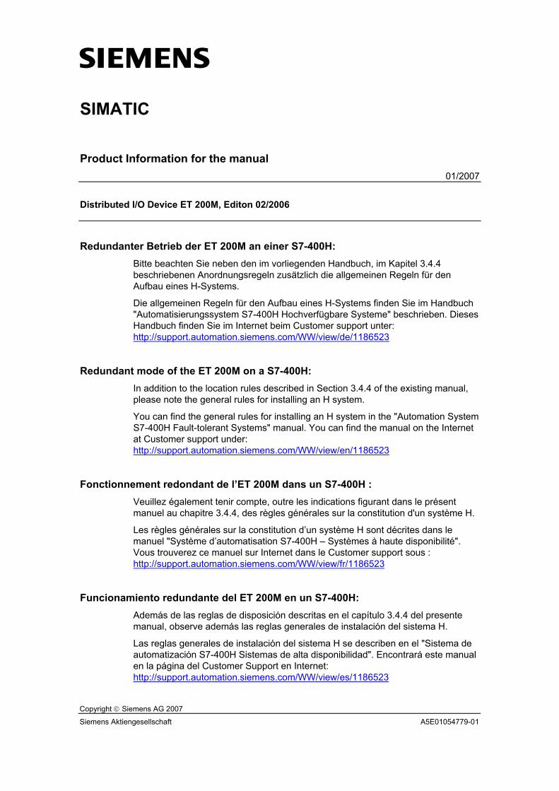
s
Copyright © Siemens AG 2007
Siemens Aktiengesellschaft A5E01054779-01
SIMATIC
Product Information for the manual 01/2007
Distributed I/O Device ET 200M, Editon 02/2006
Redundanter Betrieb der ET 200M an einer S7-400H: Bitte beachten Sie neben den im vorliegenden Handbuch, im Kapitel 3.4.4 beschriebenen Anordnungsregeln zusätzlich die allgemeinen Regeln für den Aufbau eines H-Systems.
Die allgemeinen Regeln für den Aufbau eines H-Systems finden Sie im Handbuch "Automatisierungssystem S7-400H Hochverfügbare Systeme" beschrieben. Dieses Handbuch finden Sie im Internet beim Customer support unter: http://support.automation.siemens.com/WW/view/de/1186523
Redundant mode of the ET 200M on a S7-400H: In addition to the location rules described in Section 3.4.4 of the existing manual, please note the general rules for installing an H system.
You can find the general rules for installing an H system in the "Automation System S7-400H Fault-tolerant Systems" manual. You can find the manual on the Internet at Customer support under: http://support.automation.siemens.com/WW/view/en/1186523
Fonctionnement redondant de l’ET 200M dans un S7-400H : Veuillez également tenir compte, outre les indications figurant dans le présent manuel au chapitre 3.4.4, des règles générales sur la constitution d'un système H.
Les règles générales sur la constitution d’un système H sont décrites dans le manuel "Système d’automatisation S7-400H – Systèmes à haute disponibilité". Vous trouverez ce manuel sur Internet dans le Customer support sous : http://support.automation.siemens.com/WW/view/fr/1186523
Funcionamiento redundante del ET 200M en un S7-400H: Además de las reglas de disposición descritas en el capítulo 3.4.4 del presente manual, observe además las reglas generales de instalación del sistema H.
Las reglas generales de instalación del sistema H se describen en el "Sistema de automatización S7-400H Sistemas de alta disponibilidad". Encontrará este manual en la página del Customer Support en Internet: http://support.automation.siemens.com/WW/view/es/1186523
Produktinformation zum Handbuch ET 200M 2 A5E01054779-01
Funzionamento ridondante dell'ET 200M collegata a un S7-400H: Oltre alle regole per la disposizione delle unità descritte nel capitolo 3.4.4 del presente manuale è necessario attenersi alle regole generali per la configurazione dei sistemi H.
Queste ultime sono illustrate nel manuale "Sistema di automazione S7-400H Sistemi ad elevata disponibilità" disponibile nella pagina Internet di Product Support: http://support.automation.siemens.com/WW/view/it/1186523
S7-400H での ET 200M の二重化モード:
既存マニュアルのセクション 3.4.4 で説明されているロケーション規則に加え、H システムのインストールに関する一般規則に注意してください。
H システムのインストールに関する一般規則は、「オートメーション システム S7-400H 耐障害システム (Automation System S7-400H Fault-tolerant Systems)」のマニュアルに記述されています。マニュアルは、インターネット http://support.automation.siemens.com/WW/view/ja/1186523 のカスタマ サポートにあります。
SIMATIC ET 200M Interface Module IM 153-4 PN __________________________________________________________________________________________________
Introduction 1
Description 2
Installing and connecting 3
Commissioning 4
Maintenance and service 5
Functions 6
Interrupt, error, and system messages
7
SIMATIC
ET 200M Interface Module IM 153-4 PN
Product Information
04/2007 A5E01047033-01
Safety Guidelines Safety Guidelines This manual contains notices you have to observe in order to ensure your personal safety, as well as to prevent damage to property. The notices referring to your personal safety are highlighted in the manual by a safety alert symbol, notices referring only to property damage have no safety alert symbol. These notices shown below are graded according to the degree of danger.
DANGER indicates that death or severe personal injury will result if proper precautions are not taken.
WARNING indicates that death or severe personal injury may result if proper precautions are not taken.
CAUTION with a safety alert symbol, indicates that minor personal injury can result if proper precautions are not taken.
CAUTION without a safety alert symbol, indicates that property damage can result if proper precautions are not taken.
NOTICE indicates that an unintended result or situation can occur if the corresponding information is not taken into account.
If more than one degree of danger is present, the warning notice representing the highest degree of danger will be used. A notice warning of injury to persons with a safety alert symbol may also include a warning relating to property damage.
Qualified Personnel The device/system may only be set up and used in conjunction with this documentation. Commissioning and operation of a device/system may only be performed by qualified personnel. Within the context of the safety notes in this documentation qualified persons are defined as persons who are authorized to commission, ground and label devices, systems and circuits in accordance with established safety practices and standards.
Prescribed Usage Note the following:
WARNING This device may only be used for the applications described in the catalog or the technical description and only in connection with devices or components from other manufacturers which have been approved or recommended by Siemens. Correct, reliable operation of the product requires proper transport, storage, positioning and assembly as well as careful operation and maintenance.
Trademarks All names identified by ® are registered trademarks of the Siemens AG. The remaining trademarks in this publication may be trademarks whose use by third parties for their own purposes could violate the rights of the owner.
Disclaimer of Liability We have reviewed the contents of this publication to ensure consistency with the hardware and software described. Since variance cannot be precluded entirely, we cannot guarantee full consistency. However, the information in this publication is reviewed regularly and any necessary corrections are included in subsequent editions.
Siemens AG Automation and Drives Postfach 48 48 90437 NÜRNBERG GERMANY
Ordernumber: A5E01047033-01 Ⓟ 05/2007
Copyright © Siemens AG 2007. Technical data subject to change
Interface Module IM 153-4 PN Product Information, 04/2007, A5E01047033-01 3
Table of contents 1 Introduction................................................................................................................................................ 5 2 Description................................................................................................................................................. 7
2.1 Properties of the IM 153-4 PN interface module............................................................................7 3 Installing and connecting ......................................................................................................................... 11
3.1 Installing IM 153-4 PN..................................................................................................................11 3.2 Connecting IM 153-4 PN..............................................................................................................11
4 Commissioning ........................................................................................................................................ 15 4.1 Configuring in STEP 7 .................................................................................................................15 4.2 Configuring by means of GSD file................................................................................................16 4.3 Assigning device names to the I/O device...................................................................................16 4.4 Configuring ports of the IM 153-4 PN ..........................................................................................18 4.5 Commissioning ET 200M for PROFINET IO ...............................................................................19 4.6 Startup of ET 200M on PROFINET IO.........................................................................................20
5 Maintenance and service......................................................................................................................... 21 5.1 Replacing IM 153-4 PN................................................................................................................21 5.2 Replacing the SIMATIC Micro Memory Card...............................................................................22 5.3 Update of the IM 153-4 PN ..........................................................................................................24
6 Functions ................................................................................................................................................. 27 6.1 SNMP...........................................................................................................................................27 6.2 Identification data for PROFINET IO ...........................................................................................28
7 Interrupt, error, and system messages .................................................................................................... 31 7.1 Diagnostics using LED display on IM 153-4 PN interface module ..............................................31 7.2 Diagnostic messages of the electronic modules..........................................................................33 7.3 Evaluating the interrupts of the ET 200M ....................................................................................34 7.4 Maintenance interrupts ................................................................................................................35 7.5 Channel diagnostics.....................................................................................................................36 7.6 Error types for modules................................................................................................................36 7.7 Diagnostics of incorrect configuration states of ET 200M on PROFINET IO ..............................36 7.8 Diagnostics events triggered by a STOP of the I/O controller .....................................................37
Index........................................................................................................................................................ 39

Table of contents
Interface Module IM 153-4 PN 4 Product Information, 04/2007, A5E01047033-01
Interface Module IM 153-4 PN Product Information, 04/2007, A5E01047033-01 5
Introduction 1This Product Information describes the IM 153-4 PN interface module for operation of the ET 200M with PROFINET IO. It supplements the Distributed I/O Device ET 200M Operating Instructions, Edition 02/2006.
Reference documents You can find additional information about using the IM 153-4 PN interface module in the following documents. These documents are available on the Internet at http://www.siemens.com/automation/service&support. There you can search for the documents using the specified Entry IDs. ● Distributed I/O Device ET 200M Operating Instructions; ID 1142798 ● PROFINET System Description; ID. 19292127 ● From PROFIBUS DP to PROFINET IO Programming Manual; ID 19289930 ● Programming with STEP 7, Manual; ID 18652056

Introduction
Interface Module IM 153-4 PN 6 Product Information, 04/2007, A5E01047033-01
Interface Module IM 153-4 PN Product Information, 04/2007, A5E01047033-01 7
Description 22.1 Properties of the IM 153-4 PN interface module
Order number 6ES7153-4AA00-0XB0
Properties The IM 153-4 PN interface module has the following properties: ● It interconnects the ET 200M with PROFINET IO. ● A maximum of 12 modules can be operated with the IM 153-4 PN ● It prepares the data for the inserted modules.
The following settings can be made: SM, CP, non-assignable FM ● It supplies the backplane bus ● Integrated switch with 2 ports ● Transfer and backup of the device name on SIMATIC Micro Memory Card ● Firmware update using a SIMATIC Micro Memory Card or PROFINET IO ● The reference potential M of the rated supply voltage of the IM 153-4 PN to the rail
(protective conductor) is connected by means of an RC combination, thus permitting an ungrounded configuration
● Supported Ethernet services – ping – arp – Network diagnostics (SNMP): LLDP-MIB / MIB-2 – Reset SNMP parameters to the factory settings – I&M data
● Interrupts – Diagnostic interrupts – Hardware interrupts – Removal / insertion interrupts – Maintenance interrupts
● Port diagnostics ● Port disabling ● Support for real-time communication (RT Class 1 and Class 2). ● Maximum address space of 200 bytes I/O data. ● Data records for I/O modules
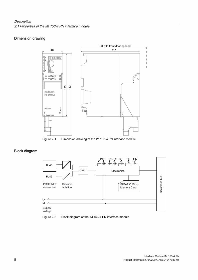
Description 2.1 Properties of the IM 153-4 PN interface module
Interface Module IM 153-4 PN 8 Product Information, 04/2007, A5E01047033-01
Dimension drawing
Figure 2-1 Dimension drawing of the IM 153-4 PN interface module
Block diagram
Figure 2-2 Block diagram of the IM 153-4 PN interface module
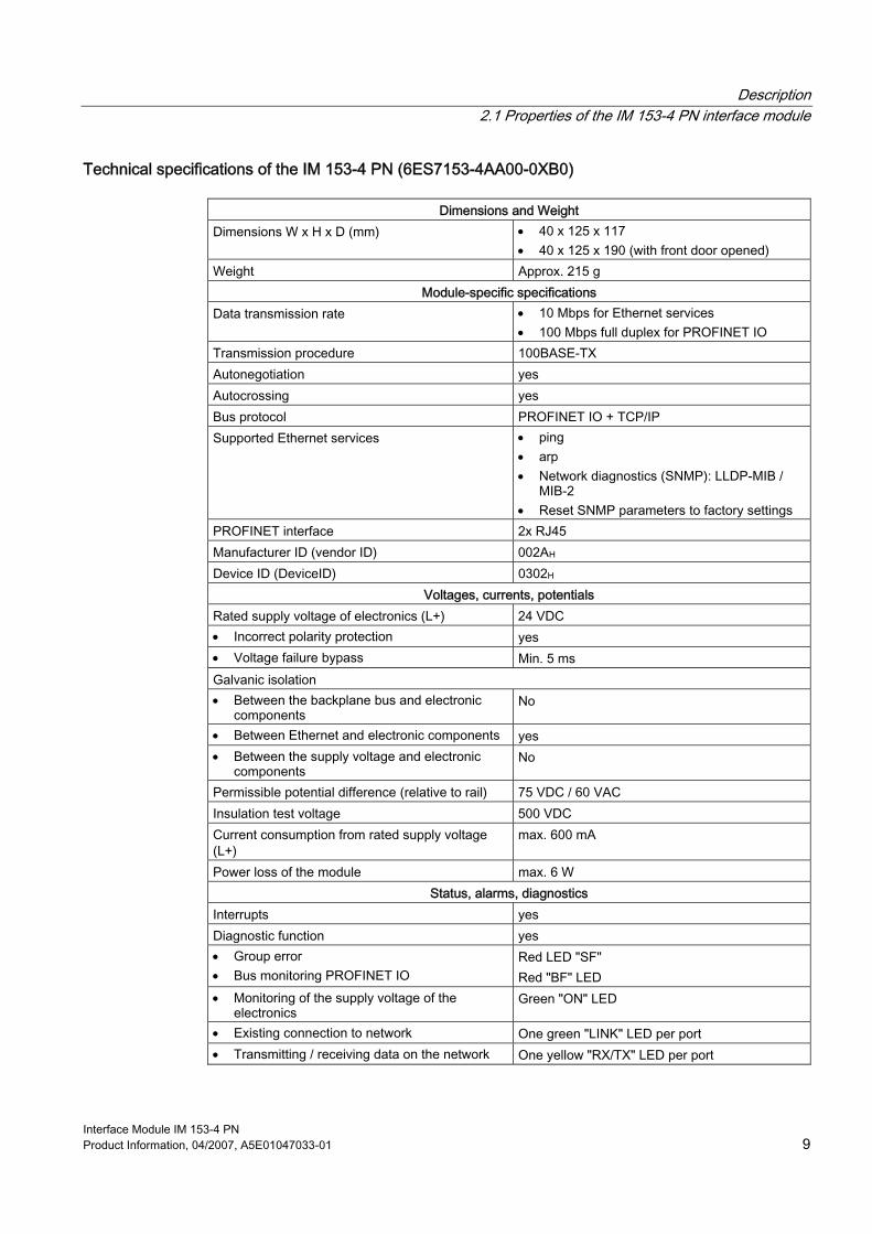
Description 2.1 Properties of the IM 153-4 PN interface module
Interface Module IM 153-4 PN Product Information, 04/2007, A5E01047033-01 9
Technical specifications of the IM 153-4 PN (6ES7153-4AA00-0XB0)
Dimensions and Weight Dimensions W x H x D (mm) • 40 x 125 x 117
• 40 x 125 x 190 (with front door opened) Weight Approx. 215 g
Module-specific specifications Data transmission rate • 10 Mbps for Ethernet services
• 100 Mbps full duplex for PROFINET IO Transmission procedure 100BASE-TX Autonegotiation yes Autocrossing yes Bus protocol PROFINET IO + TCP/IP Supported Ethernet services • ping
• arp • Network diagnostics (SNMP): LLDP-MIB /
MIB-2 • Reset SNMP parameters to factory settings
PROFINET interface 2x RJ45 Manufacturer ID (vendor ID) 002AH Device ID (DeviceID) 0302H
Voltages, currents, potentials Rated supply voltage of electronics (L+) 24 VDC • Incorrect polarity protection yes • Voltage failure bypass Min. 5 ms Galvanic isolation • Between the backplane bus and electronic
components No
• Between Ethernet and electronic components yes • Between the supply voltage and electronic
components No
Permissible potential difference (relative to rail) 75 VDC / 60 VAC Insulation test voltage 500 VDC Current consumption from rated supply voltage (L+)
max. 600 mA
Power loss of the module max. 6 W Status, alarms, diagnostics
Interrupts yes Diagnostic function yes • Group error • Bus monitoring PROFINET IO
Red LED "SF" Red "BF" LED
• Monitoring of the supply voltage of the electronics
Green "ON" LED
• Existing connection to network One green "LINK" LED per port • Transmitting / receiving data on the network One yellow "RX/TX" LED per port

Description 2.1 Properties of the IM 153-4 PN interface module
Interface Module IM 153-4 PN 10 Product Information, 04/2007, A5E01047033-01
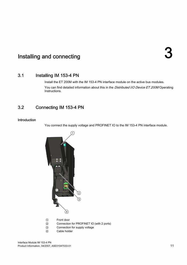
Interface Module IM 153-4 PN Product Information, 04/2007, A5E01047033-01 11
Installing and connecting 33.1 Installing IM 153-4 PN
Install the ET 200M with the IM 153-4 PN interface module on the active bus modules. You can find detailed information about this in the Distributed I/O Device ET 200M Operating Instructions.
3.2 Connecting IM 153-4 PN
Introduction You connect the supply voltage and PROFINET IO to the IM 153-4 PN interface module.
① Front door ② Connection for PROFINET IO (with 2 ports) ③ Connection for supply voltage ④ Cable holder
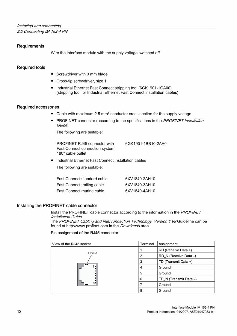
Installing and connecting 3.2 Connecting IM 153-4 PN
Interface Module IM 153-4 PN 12 Product Information, 04/2007, A5E01047033-01
Requirements Wire the interface module with the supply voltage switched off.
Required tools ● Screwdriver with 3 mm blade ● Cross-tip screwdriver, size 1 ● Industrial Ethernet Fast Connect stripping tool (6GK1901-1GA00)
(stripping tool for Industrial Ethernet Fast Connect installation cables)
Required accessories ● Cable with maximum 2.5 mm2 conductor cross section for the supply voltage ● PROFINET connector (according to the specifications in the PROFINET Installation
Guide) The following are suitable:
PROFINET RJ45 connector with
Fast Connect connection system, 180° cable outlet
6GK1901-1BB10-2AA0
● Industrial Ethernet Fast Connect installation cables The following are suitable:
Fast Connect standard cable 6XV1840-2AH10 Fast Connect trailing cable 6XV1840-3AH10 Fast Connect marine cable 6XV1840-4AH10
Installing the PROFINET cable connector Install the PROFINET cable connector according to the information in the PROFINET Installation Guide. The PROFINET Cabling and Interconnection Technology, Version 1.99 Guideline can be found at http://www.profinet.com in the Downloads area. Pin assignment of the RJ45 connector
View of the RJ45 socket Terminal Assignment
1 RD (Receive Data +) 2 RD_N (Receive Data –) 3 TD (Transmit Data +) 4 Ground 5 Ground 6 TD_N (Transmit Data –) 7 Ground
8 Ground
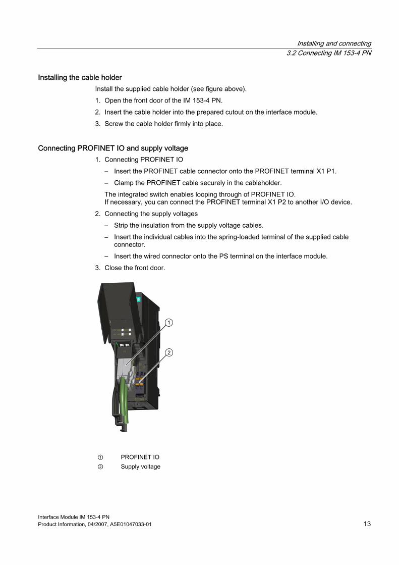
Installing and connecting 3.2 Connecting IM 153-4 PN
Interface Module IM 153-4 PN Product Information, 04/2007, A5E01047033-01 13
Installing the cable holder Install the supplied cable holder (see figure above). 1. Open the front door of the IM 153-4 PN. 2. Insert the cable holder into the prepared cutout on the interface module. 3. Screw the cable holder firmly into place.
Connecting PROFINET IO and supply voltage 1. Connecting PROFINET IO
– Insert the PROFINET cable connector onto the PROFINET terminal X1 P1. – Clamp the PROFINET cable securely in the cableholder. The integrated switch enables looping through of PROFINET IO. If necessary, you can connect the PROFINET terminal X1 P2 to another I/O device.
2. Connecting the supply voltages – Strip the insulation from the supply voltage cables. – Insert the individual cables into the spring-loaded terminal of the supplied cable
connector. – Insert the wired connector onto the PS terminal on the interface module.
3. Close the front door.
① PROFINET IO ② Supply voltage

Installing and connecting 3.2 Connecting IM 153-4 PN
Interface Module IM 153-4 PN 14 Product Information, 04/2007, A5E01047033-01
Interface Module IM 153-4 PN Product Information, 04/2007, A5E01047033-01 15
Commissioning 44.1 Configuring in STEP 7
Introduction The ET 200M is listed in the hardware catalog of HW Config after you start STEP 7.
Requirements ● STEP 7 Version 5.4 Service Pack 2 or higher ● Device name assigned to the I/O device. See the chapter Assigning device names for I/O
devices.
Procedure 1. Start SIMATIC Manager. 2. Create a new project. 3. Configure the ET 200M with HW Config. 4. Move the modules from the hardware catalog to the configuration table using a drag-and-
drop operation. 5. Double-click the first module of the ET 200M in the configuration table, and set its
parameters. 6. Assign parameters for the other modules of the ET 200M. 7. Save the configuration, or download it to the I/O controller.
Reference For addtional information, refer to the STEP 7 Online Help.
Commissioning 4.2 Configuring by means of GSD file
Interface Module IM 153-4 PN 16 Product Information, 04/2007, A5E01047033-01
4.2 Configuring by means of GSD file
Introduction The GSD file allows you to configure the ET 200M using STEP 7 V5.4, Service Pack 2 or higher. To do so you must install the GSD in the configuration software beforehand.
Requirements A GSD file, available for download from the Internet at: http://www.siemens.com/automation/service&support, entry ID 25057900 Interface Module IM 153-4 PN: GSDML-V1.0-Siemens-ET200M-"date in yyyymmdd format".xml
Configuring the ET 200M on PROFINET IO with STEP 7 1. Start STEP 7 and then select the Tools > Install New GSD file menu command in HW
Config. 2. Select the GSDML file to install from the next dialog box, then confirm with OK. Result:
The ET 200M appears in the PROFINET IO folder of the hardware catalog. 3. Further procedures are the same as in Configuring in STEP 7.
4.3 Assigning device names to the I/O device
Introduction Each PROFINET IO device is assigned a unique device ID at the factory (MAC address). For configuration and in the user program, each ET 200M I/O device is addressed with its device name. You can find detailed information about addressing on PROFINET IO in the PROFINET System Description. This document is available on the Internet at http://www.siemens.com/automation/service&support, entry ID19292127.
Requirements ● Interface Module IM 153-4 PN ● SIMATIC Micro Memory Card 64k and higher ● The programming device must be online on PROFINET to the I/O device to let you assign
a device name to the interface module. ● The I/O device is configured in HW Config and assigned an IP address.
Commissioning 4.3 Assigning device names to the I/O device
Interface Module IM 153-4 PN Product Information, 04/2007, A5E01047033-01 17
Assigning device names 1. Insert an empty SIMATIC Micro Memory Card into the module slot on the front of the
IM 153-4 PN interface module. 2. Switch on the voltage supply for the IM 153-4 PN. 3. In HW Config, open the "Properties - IM 153-4 PN" window, enter the device name for the
I/O device, and then confirm your entry with "OK". Do not use the device name "noname".
Transferring the device name to the interface module. 1. In HW Config, select "PLC > Ethernet > Assign Device Name". 2. Click "Assign Name" in the "Assign Device Name" window.
Result The device name is saved on the SIMATIC Micro Memory Card in the IM 153-4 PN interface module.
Forwarding the device name on replacement of the interface module The device name of the I/O device is saved on the SIMATIC Micro Memory Card. To pass the device name when an IM 153-4 PN interface module is replaced, move the SIMATIC Micro Memory Card from the "old" interface module to the "new" one. The I/O device takes the device name from the SIMATIC Micro Memory Card after the supply voltage is switched off and on. The station can be addressed again and will operate as before the replacement.
Station flash test If you use more than one I/O device, the "Assign device name" dialog also displays more than one I/O device. In this case, you should compare the MAC address of the device with the indicated MAC address and select the proper I/O device. The identification of I/O devices in a system is facilitated by a node flash test. To activate the flash test: 1. Select one of the indicated I/O devices from the "Assign device name" dialog box. 2. Select the flash period you want to use. 3. Press the "Flash on" button. The LINK LED flashes on the selected I/O device. If PROFINET IO is looped, both LINK LEDs will flash.
Commissioning 4.4 Configuring ports of the IM 153-4 PN
Interface Module IM 153-4 PN 18 Product Information, 04/2007, A5E01047033-01
4.4 Configuring ports of the IM 153-4 PN
Introduction The IM 153-4 PN interface module can diagnose both of its ports: X1 P1 and X1 P2.
Requirement ● The ports must be configured in HW Config. ● The port diagnostics must be released.
Configuring ports in HW Config Configure both ports of the IM 153-4 PN in HW Config in the "Properties of the IM 153-4 PN port..." dialog: ● Addresses tab:
Specify the diagnostic address of each port. ● Topology tab:
Specify a "Port interconnection". ● Options tab:
To enable the port diagnostics, select the following for "Connection" under "Transmission Medium / Duplex": "Automatic Settings (monitor)".
Reference See STEP 7 Online Help.
Commissioning 4.5 Commissioning ET 200M for PROFINET IO
Interface Module IM 153-4 PN Product Information, 04/2007, A5E01047033-01 19
4.5 Commissioning ET 200M for PROFINET IO
Introduction You commission the automation system according to the relevant plant configuration. The following procedure describes the commissioning of the ET 200M on an I/O controller.
Requirements for the ET 200M on PROFINET IO
Actions Reference ET 200M installed ET 200M Operating Instructions, Chapter
Installation ET 200M wired Chapter Installing and connecting The SIMATIC Micro Memory Card is inserted Chapter Service and maintenance Device name for I/O device assigned Chapter Commissioning ET 200M configured Chapter Commissioning Supply voltage to the I/O controller is switched on I/O Controller Manual I/O controller is switched to RUN mode I/O Controller Manual
Commissioning the ET 200M 1. Switch on the supply voltage for the ET 200 M. 2. If necessary, switch on the supply voltage for the load.
Note Changes of the backplane bus If you change the backplane bus (e.g., number of modules), a Power Off/Power On of the supply voltage for the ET 200M is required.
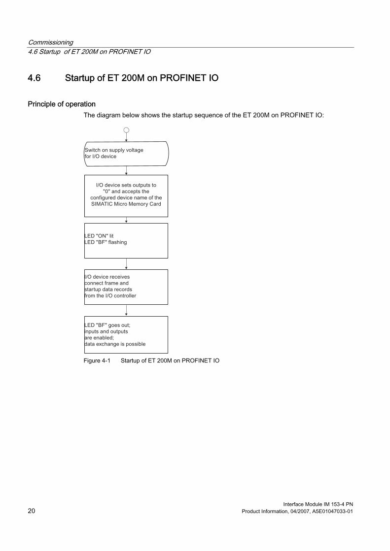
Commissioning 4.6 Startup of ET 200M on PROFINET IO
Interface Module IM 153-4 PN 20 Product Information, 04/2007, A5E01047033-01
4.6 Startup of ET 200M on PROFINET IO
Principle of operation The diagram below shows the startup sequence of the ET 200M on PROFINET IO:
Figure 4-1 Startup of ET 200M on PROFINET IO
Interface Module IM 153-4 PN Product Information, 04/2007, A5E01047033-01 21
Maintenance and service 55.1 Replacing IM 153-4 PN
Initial situation The IM 153-4 PN is installed. A new IM 153-4 PN of the same type should be installed.
Slot numbering If you have provided the modules in your system with slot numbering, when replacing modules you must remove the numbering from the old module and then reuse it in the new module.
Requirement When replacing the interface module, you must switch off the supply voltage on the defective module.
CAUTION Removing the IM 153-4 PN interface module When you switch off the supply voltage to an ET 200M on PROFINET IO, the integrated switch will also cause a failure of all downstream I/O devices.
Removing a module To remove the module, proceed as follows: 1. With the on / off switch of the power supply module to 0
( : output voltages 0 V). 2. Remove the PROFINET cable connector. 3. Remove the cable connector for the supply voltage. 4. Remove the SIMATIC Micro Memory Card from the module slot. 5. Loosen the fixing screws of the IM 153-4 PN. 6. Swivel out the IM 153-4 PN.
Maintenance and service 5.2 Replacing the SIMATIC Micro Memory Card
Interface Module IM 153-4 PN 22 Product Information, 04/2007, A5E01047033-01
Installing a new module Install the new module as follows: 1. Hang up the new IM 153-4 PN and swivel it downward. 2. Screw the module on securely. 3. Insert the PROFINET cable connector. 4. Take the SIMATIC Micro Memory Card containing the device name from the "old"
interface module and insert it in the module slot of the "new" interface module. 5. Insert the cable connector for the supply voltage. 6. Put the standby switch of the power supply module into the 1 position (output voltages to
rated value).
Response of the ET 200M after module replacement If a fault is present after module replacement, you can use STEP 7 to evaluate the cause of the fault in the corresponding diagnostic data record.
5.2 Replacing the SIMATIC Micro Memory Card
Introduction A SIMATIC Micro Memory Card is used as the storage medium for the IM 153-4 PN. The MMC can be used as a portable data medium. You can either save technology data (device names) or data for a firmware update on a SIMATIC Micro Memory Card.
Service life of a SIMATIC Micro Memory Card The life of an SIMATIC Micro Memory Card depends mainly on the following factors: ● Number of deletion or programming cycles ● External factors, such as ambient temperature At an ambient temperature up to 60 °C, a SIMATIC Micro Memory Card has a service life of 10 years with a maximum of 100,000 write/delete operations.
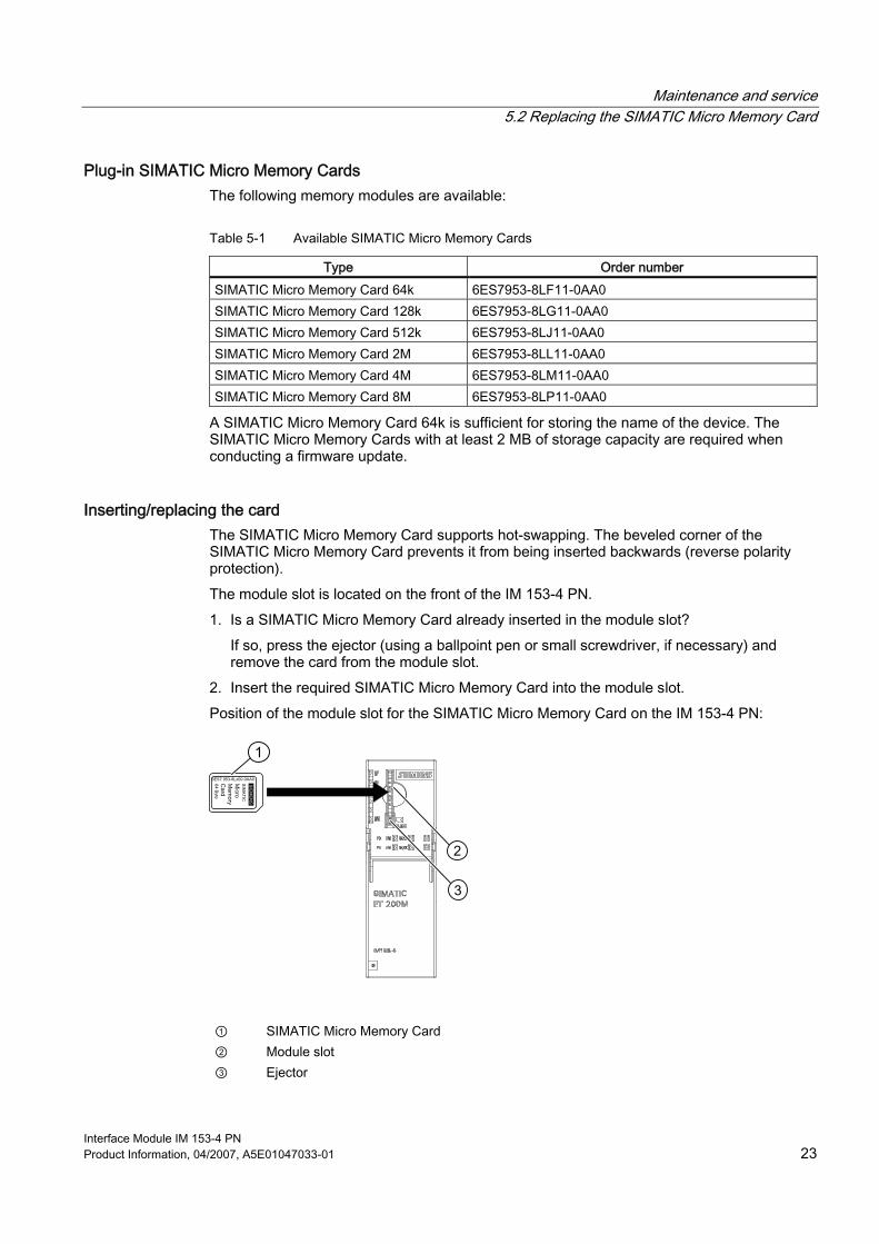
Maintenance and service 5.2 Replacing the SIMATIC Micro Memory Card
Interface Module IM 153-4 PN Product Information, 04/2007, A5E01047033-01 23
Plug-in SIMATIC Micro Memory Cards The following memory modules are available:
Table 5-1 Available SIMATIC Micro Memory Cards
Type Order number SIMATIC Micro Memory Card 64k 6ES7953-8LF11-0AA0 SIMATIC Micro Memory Card 128k 6ES7953-8LG11-0AA0 SIMATIC Micro Memory Card 512k 6ES7953-8LJ11-0AA0 SIMATIC Micro Memory Card 2M 6ES7953-8LL11-0AA0 SIMATIC Micro Memory Card 4M 6ES7953-8LM11-0AA0 SIMATIC Micro Memory Card 8M 6ES7953-8LP11-0AA0
A SIMATIC Micro Memory Card 64k is sufficient for storing the name of the device. The SIMATIC Micro Memory Cards with at least 2 MB of storage capacity are required when conducting a firmware update.
Inserting/replacing the card The SIMATIC Micro Memory Card supports hot-swapping. The beveled corner of the SIMATIC Micro Memory Card prevents it from being inserted backwards (reverse polarity protection). The module slot is located on the front of the IM 153-4 PN. 1. Is a SIMATIC Micro Memory Card already inserted in the module slot?
If so, press the ejector (using a ballpoint pen or small screwdriver, if necessary) and remove the card from the module slot.
2. Insert the required SIMATIC Micro Memory Card into the module slot. Position of the module slot for the SIMATIC Micro Memory Card on the IM 153-4 PN:
1
2
3
① SIMATIC Micro Memory Card ② Module slot ③ Ejector
Maintenance and service 5.3 Update of the IM 153-4 PN
Interface Module IM 153-4 PN 24 Product Information, 04/2007, A5E01047033-01
5.3 Update of the IM 153-4 PN
Where do you obtain the latest firmware version? The latest firmware versions can be obtained from your Siemens representative or from the Internet: http://www.siemens.com/automation/service&support Note: An updated firmware version is not currently available for the IM 153-4 PN. Tip: ● Prior to the update note down the current version of your firmware. ● If there are any problems with the latest firmware you can then still download the current
firmware from the Internet and transfer it to the interface module again.
Basics An update is possible with IM 153-4 PN as of order number 6ES7153-4AA00-0XB0. For this you require STEP 7 V5.4 SP 2 or higher. There are two ways of updating: ● from PG/PC via PROFINET IO (direct) ● via SIMATIC Micro Memory Card After a successful update, the former version of the IM 153-4 PN firmware must be covered over with a sticker showing the updated version of the firmware.
Requirements Update via PROFINET IO ● The IM 153-4 PN in the station that is to be updated must be available online. ● The files with the current (new) version of the firmware must be available in the file
system of your PD / PC. Update via SIMATIC Micro Memory Card ● The update files must be available on the SIMATIC Micro Memory Card.
NOTICE When the firmware is updated, the stations in a line can fail.
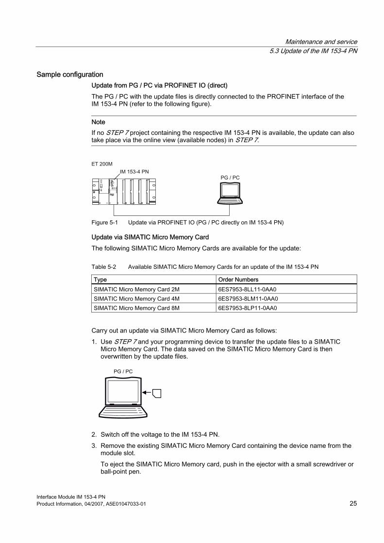
Maintenance and service 5.3 Update of the IM 153-4 PN
Interface Module IM 153-4 PN Product Information, 04/2007, A5E01047033-01 25
Sample configuration Update from PG / PC via PROFINET IO (direct) The PG / PC with the update files is directly connected to the PROFINET interface of the IM 153-4 PN (refer to the following figure).
Note If no STEP 7 project containing the respective IM 153-4 PN is available, the update can also take place via the online view (available nodes) in STEP 7.
Figure 5-1 Update via PROFINET IO (PG / PC directly on IM 153-4 PN)
Update via SIMATIC Micro Memory Card The following SIMATIC Micro Memory Cards are available for the update:
Table 5-2 Available SIMATIC Micro Memory Cards for an update of the IM 153-4 PN
Type Order Numbers SIMATIC Micro Memory Card 2M 6ES7953-8LL11-0AA0 SIMATIC Micro Memory Card 4M 6ES7953-8LM11-0AA0 SIMATIC Micro Memory Card 8M 6ES7953-8LP11-0AA0
Carry out an update via SIMATIC Micro Memory Card as follows: 1. Use STEP 7 and your programming device to transfer the update files to a SIMATIC
Micro Memory Card. The data saved on the SIMATIC Micro Memory Card is then overwritten by the update files.
2. Switch off the voltage to the IM 153-4 PN. 3. Remove the existing SIMATIC Micro Memory Card containing the device name from the
module slot. To eject the SIMATIC Micro Memory card, push in the ejector with a small screwdriver or ball-point pen.
Maintenance and service 5.3 Update of the IM 153-4 PN
Interface Module IM 153-4 PN 26 Product Information, 04/2007, A5E01047033-01
4. Insert the SIMATIC Micro Memory Card containing the update into the module slot.
5. Switch on the voltage. – The IM 153-4 PN automatically detects the SIMATIC Micro Memory card with the
update files and starts the update. – During the update the SF and the BF LEDs light up. – After the update is concluded the BF LED flashes at 0.5 Hz.
6. Switch off the voltage to the IM 153-4 PN and remove the SIMATIC Micro Memory card with update.
7. Re-insert the SIMATIC Micro Memory Card containing the device name into the module slot and then switch on the supply voltage.
Restart after update Update via PROFINET IO In the STEP 7 user interface, it is possible to set whether ● The IM 153-4 PN should automatically perform a reset after a successful update in order
to start up using the new firmware.
CAUTION
If the "activate firmware after download" field is checked there is a brief station failure of the ET 200M. If no precautions have been taken for this case, then the update causes the CPU (of the I/O controller) to go to STOP mode due to a rack failure.
● The IM 153-4 PN must be reset by switching off the supply voltage. Then, when the supply voltage is switched on again, the IM 153-4 PN will start up using the new firmware.
Update via SIMATIC Micro Memory Card If the update was successful, the IM 153-4 PN starts up with the new firmware and is then ready for operation.
Update unsuccessful If the update fails, the next time the supply voltage is switched off and on the IM 153-4 PN starts up with the current ("old") firmware.
Interface Module IM 153-4 PN Product Information, 04/2007, A5E01047033-01 27
Functions 66.1 SNMP
The IM 153-4 PN supports the SNMP Ethernet service. LLDP-MIB and MIB-2 (RFC1213) are supported. R / W objects can be changed using SNMP tools and are saved in the module. Following replacement with a factory-new module, the R / W objects of the interface module are set to factory settings.
Resetting SNMP parameters to factory settings
NOTICE When factory settings are restored, the stations in a line can fail.
"Reset to factory settings" is only possible if the I/O device is not exchanging data with an I/O controller. To reset retentively-stored SNMP parameters to factory settings (STEP 7 V5.4 SP 2 and higher), select Target system > Ethernet > Edit Ethernet node and press the Reset button under Reset to factory settings. The following data is not deleted when resetting: ● The device name saved on the SIMATIC Micro Memory Card ● The MAC address ● I&M data
Note Deleting the device name To prevent a new module with a "strange" device name from starting, delete the device name from the SIMATIC Micro Memory Card. Open the properties dialog box of the interface module in HW Config. Confirm the properties dialog box without entering a device name in the Assign device name field.
Functions 6.2 Identification data for PROFINET IO
Interface Module IM 153-4 PN 28 Product Information, 04/2007, A5E01047033-01
6.2 Identification data for PROFINET IO
Definition Identification data are data that are stored in a module for assisting the user in: ● checking the system configuration ● locating modified system hardware ● troubleshooting a system Identification data enable modules to be uniquely identified online. In STEP 7, the identification data are displayed in the "Module Information - IM 153" and "Properties ..." tabs (see STEP 7 Online Help).
Reading of identification data You can directly access specific identification data by selecting Read data record. Obtain the corresponding part of the identification data under the associated data record index. The data records are structured as follows:
Table 6-1 Basic structure of data records with identification data for PROFINET IO
Contents Length (bytes) Coding (hex) Header information BlockType 2 I&M0: 0020
I&M1: 0021 I&M2: 0022 I&M3: 0023
BlockLength 2 I&M0: 0038 I&M1: 0038 I&M2: 0012 I&M3: 0038
BlockVersionHigh 1 01 BlockVersionLow 1 00 Identification data Identification data (see table below)
I&M0 / Index AFF0 hex: 54 I&M1 / Index AFF1 hex: 54 I&M2 / Index AFF2 hex: 16 I&M3 / Index AFF3 hex: 54
The data structures in the data records correspond to the PROFINET IO definitions.
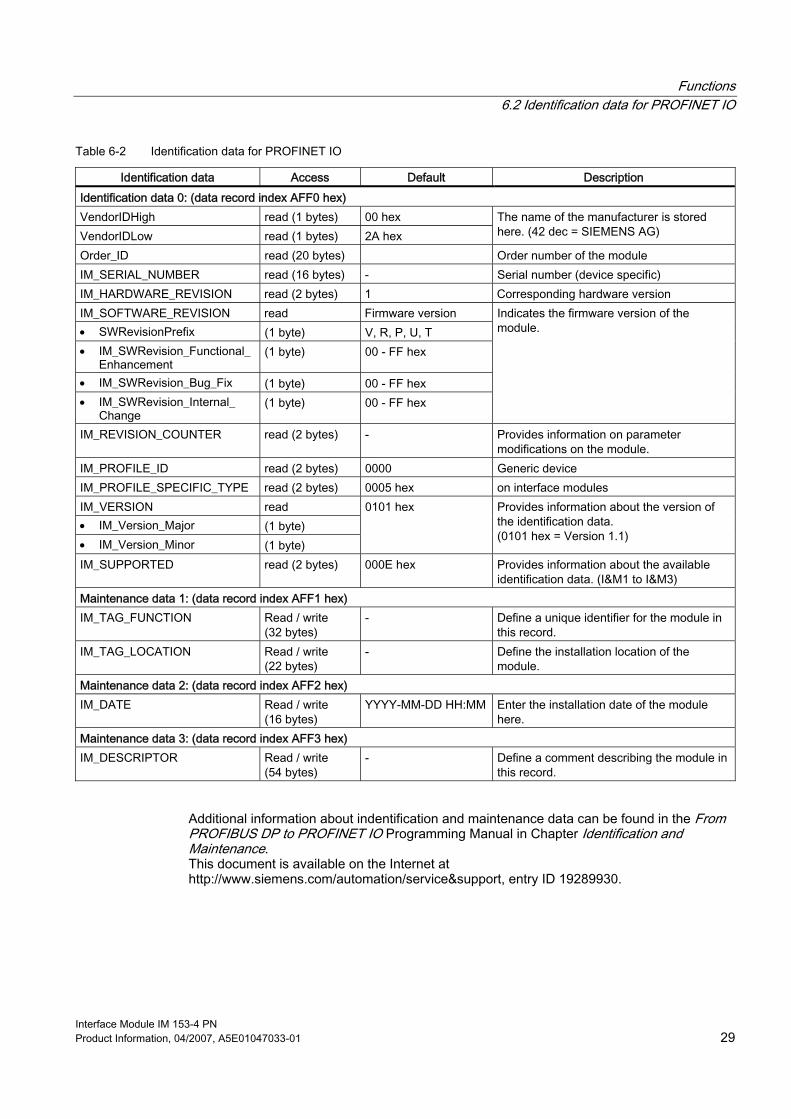
Functions 6.2 Identification data for PROFINET IO
Interface Module IM 153-4 PN Product Information, 04/2007, A5E01047033-01 29
Table 6-2 Identification data for PROFINET IO
Identification data Access Default Description Identification data 0: (data record index AFF0 hex) VendorIDHigh read (1 bytes) 00 hex VendorIDLow read (1 bytes) 2A hex
The name of the manufacturer is stored here. (42 dec = SIEMENS AG)
Order_ID read (20 bytes) Order number of the module IM_SERIAL_NUMBER read (16 bytes) - Serial number (device specific) IM_HARDWARE_REVISION read (2 bytes) 1 Corresponding hardware version IM_SOFTWARE_REVISION read Firmware version • SWRevisionPrefix (1 byte) V, R, P, U, T • IM_SWRevision_Functional_
Enhancement (1 byte) 00 - FF hex
• IM_SWRevision_Bug_Fix (1 byte) 00 - FF hex • IM_SWRevision_Internal_
Change (1 byte) 00 - FF hex
Indicates the firmware version of the module.
IM_REVISION_COUNTER read (2 bytes) - Provides information on parameter modifications on the module.
IM_PROFILE_ID read (2 bytes) 0000 Generic device IM_PROFILE_SPECIFIC_TYPE read (2 bytes) 0005 hex on interface modules IM_VERSION read • IM_Version_Major (1 byte) • IM_Version_Minor (1 byte)
0101 hex Provides information about the version of the identification data. (0101 hex = Version 1.1)
IM_SUPPORTED read (2 bytes) 000E hex Provides information about the available identification data. (I&M1 to I&M3)
Maintenance data 1: (data record index AFF1 hex) IM_TAG_FUNCTION Read / write
(32 bytes) - Define a unique identifier for the module in
this record. IM_TAG_LOCATION Read / write
(22 bytes) - Define the installation location of the
module. Maintenance data 2: (data record index AFF2 hex) IM_DATE Read / write
(16 bytes) YYYY-MM-DD HH:MM Enter the installation date of the module
here. Maintenance data 3: (data record index AFF3 hex) IM_DESCRIPTOR Read / write
(54 bytes) - Define a comment describing the module in
this record.
Additional information about indentification and maintenance data can be found in the From PROFIBUS DP to PROFINET IO Programming Manual in Chapter Identification and Maintenance. This document is available on the Internet at http://www.siemens.com/automation/service&support, entry ID 19289930.

Functions 6.2 Identification data for PROFINET IO
Interface Module IM 153-4 PN 30 Product Information, 04/2007, A5E01047033-01
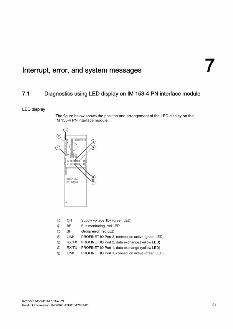
Interface Module IM 153-4 PN Product Information, 04/2007, A5E01047033-01 31
Interrupt, error, and system messages 77.1 Diagnostics using LED display on IM 153-4 PN interface module
LED display The figure below shows the position and arrangement of the LED display on the IM 153-4 PN interface module:
① ON Supply voltage 1L+ (green LED) ② BF Bus monitoring, red LED ③ SF Group error, red LED ④ LINK PROFINET IO Port 2, connection active (green LED) ⑤ RX/TX PROFINET IO Port 2, data exchange (yellow LED) ⑥ RX/TX PROFINET IO Port 1, data exchange (yellow LED) ⑦ LINK PROFINET IO Port 1, connection active (green LED)
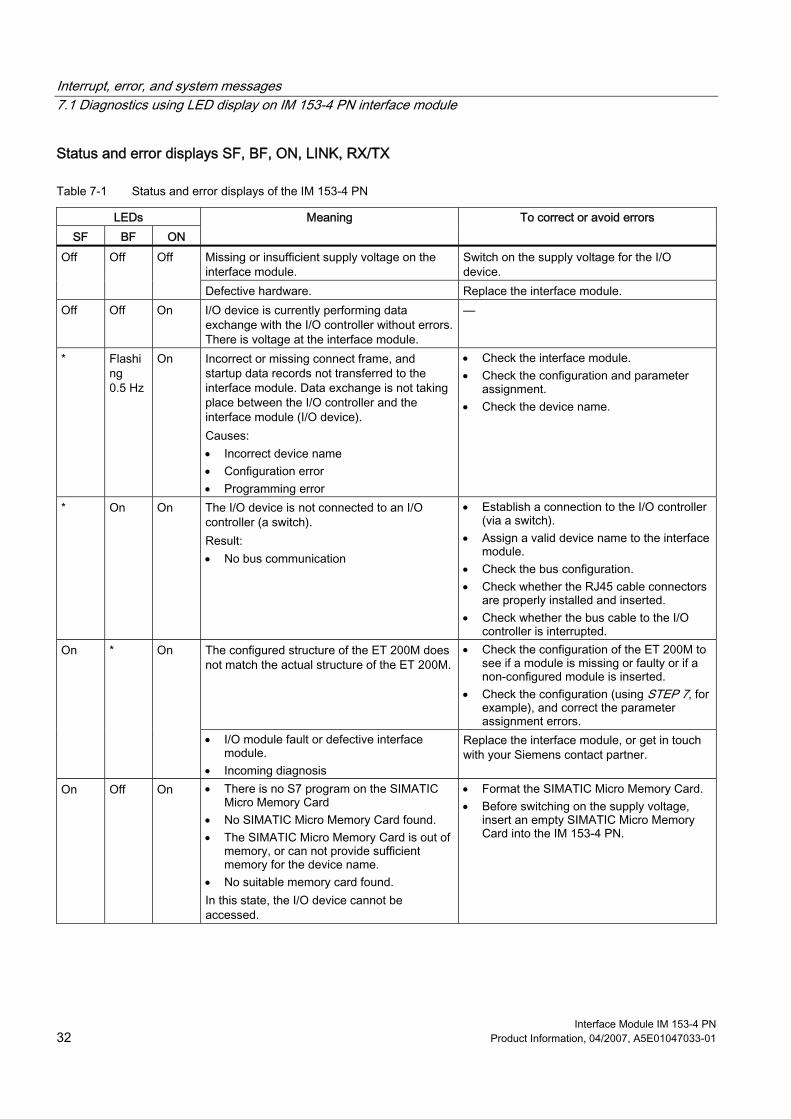
Interrupt, error, and system messages 7.1 Diagnostics using LED display on IM 153-4 PN interface module
Interface Module IM 153-4 PN 32 Product Information, 04/2007, A5E01047033-01
Status and error displays SF, BF, ON, LINK, RX/TX
Table 7-1 Status and error displays of the IM 153-4 PN
LEDs SF BF ON
Meaning To correct or avoid errors
Missing or insufficient supply voltage on the interface module.
Switch on the supply voltage for the I/O device.
Off Off Off
Defective hardware. Replace the interface module. Off Off On I/O device is currently performing data
exchange with the I/O controller without errors. There is voltage at the interface module.
—
* Flashing 0.5 Hz
On Incorrect or missing connect frame, and startup data records not transferred to the interface module. Data exchange is not taking place between the I/O controller and the interface module (I/O device). Causes: • Incorrect device name • Configuration error • Programming error
• Check the interface module. • Check the configuration and parameter
assignment. • Check the device name.
* On On The I/O device is not connected to an I/O controller (a switch). Result: • No bus communication
• Establish a connection to the I/O controller (via a switch).
• Assign a valid device name to the interface module.
• Check the bus configuration. • Check whether the RJ45 cable connectors
are properly installed and inserted. • Check whether the bus cable to the I/O
controller is interrupted. The configured structure of the ET 200M does not match the actual structure of the ET 200M.
• Check the configuration of the ET 200M to see if a module is missing or faulty or if a non-configured module is inserted.
• Check the configuration (using STEP 7, for example), and correct the parameter assignment errors.
On * On
• I/O module fault or defective interface module.
• Incoming diagnosis
Replace the interface module, or get in touch with your Siemens contact partner.
On Off On • There is no S7 program on the SIMATIC Micro Memory Card
• No SIMATIC Micro Memory Card found. • The SIMATIC Micro Memory Card is out of
memory, or can not provide sufficient memory for the device name.
• No suitable memory card found. In this state, the I/O device cannot be accessed.
• Format the SIMATIC Micro Memory Card. • Before switching on the supply voltage,
insert an empty SIMATIC Micro Memory Card into the IM 153-4 PN.
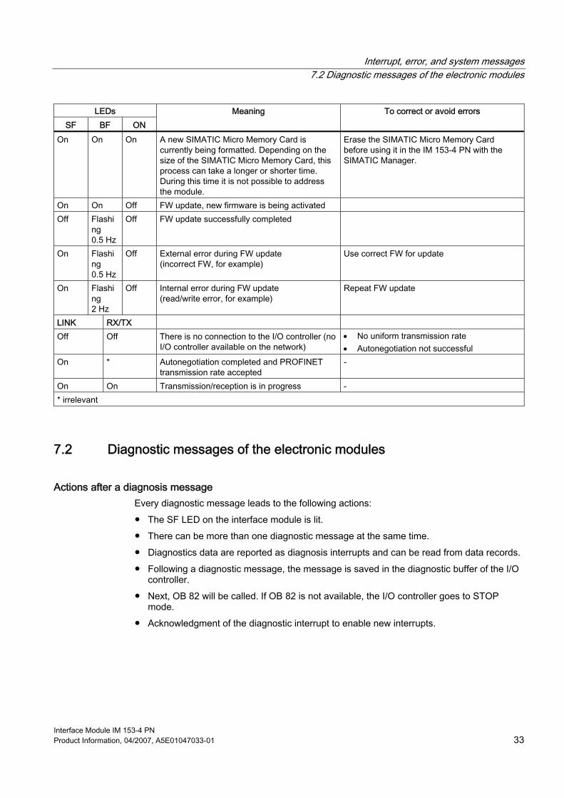
Interrupt, error, and system messages 7.2 Diagnostic messages of the electronic modules
Interface Module IM 153-4 PN Product Information, 04/2007, A5E01047033-01 33
LEDs SF BF ON
Meaning To correct or avoid errors
On On On A new SIMATIC Micro Memory Card is currently being formatted. Depending on the size of the SIMATIC Micro Memory Card, this process can take a longer or shorter time. During this time it is not possible to address the module.
Erase the SIMATIC Micro Memory Card before using it in the IM 153-4 PN with the SIMATIC Manager.
On On Off FW update, new firmware is being activated Off Flashi
ng 0.5 Hz
Off FW update successfully completed
On Flashing 0.5 Hz
Off External error during FW update (incorrect FW, for example)
Use correct FW for update
On Flashing 2 Hz
Off Internal error during FW update (read/write error, for example)
Repeat FW update
LINK RX/TX Off Off There is no connection to the I/O controller (no
I/O controller available on the network) • No uniform transmission rate • Autonegotiation not successful
On * Autonegotiation completed and PROFINET transmission rate accepted
-
On On Transmission/reception is in progress - * irrelevant
7.2 Diagnostic messages of the electronic modules
Actions after a diagnosis message Every diagnostic message leads to the following actions: ● The SF LED on the interface module is lit. ● There can be more than one diagnostic message at the same time. ● Diagnostics data are reported as diagnosis interrupts and can be read from data records. ● Following a diagnostic message, the message is saved in the diagnostic buffer of the I/O
controller. ● Next, OB 82 will be called. If OB 82 is not available, the I/O controller goes to STOP
mode. ● Acknowledgment of the diagnostic interrupt to enable new interrupts.
Interrupt, error, and system messages 7.3 Evaluating the interrupts of the ET 200M
Interface Module IM 153-4 PN 34 Product Information, 04/2007, A5E01047033-01
7.3 Evaluating the interrupts of the ET 200M
Introduction The I/O device initiates interrupts when certain errors occur. The interrupt evaluation is dependent on the utilized I/O controller.
Evaluating interrupts with I/O controller The ET 200M supports the following interrupts: ● Diagnostic interrupts ● Hardware interrupts ● Removal / insertion interrupts ● Maintenance interrupts An interrupt automatically initiates execution of the interrupt OBs in the CPU of the I/O controller (see the Programming with STEP 7 Manual, Chapter "Basics of Designing a Program Structure). Information on the cause and class of the error is already available based on the OB number and start information. To obtain detailed information about the error event, call the error OB using SFB 54 "RALRM" (read additional interrupt information).
Triggering of a diagnostics interrupt In case of an incoming or outgoing event (for example, a wire break), the module triggers a diagnostics interrupt if "Enable: Diagnostics interrupt" is set. The CPU interrupts processing of the user program and executes the OB 82 diagnostic block instead. The event that triggered the interrupt is entered in the OB 82 start information.
Triggering a hardware interrupt If a hardware interrupt occurs, the CPU interrupts the user program execution and executes hardware interrupt block OB 40. The event that triggered the interrupt is entered into the OB 40 start information.
Note Hardware interrupts should not be used for technological purposes (cyclic generation of hardware interrupts, for example), because these can become lost in the entire system.
Triggering a removal / insertion interrupt The CPU interrupts processing of the user program and processes the OB 83 diagnostic block instead. The event that triggered the interrupt is entered in the OB 83 start information.
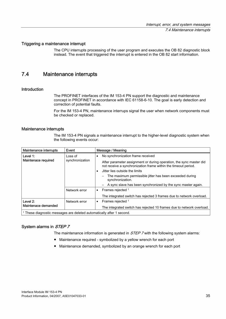
Interrupt, error, and system messages 7.4 Maintenance interrupts
Interface Module IM 153-4 PN Product Information, 04/2007, A5E01047033-01 35
Triggering a maintenance interrupt The CPU interrupts processing of the user program and executes the OB 82 diagnostic block instead. The event that triggered the interrupt is entered in the OB 82 start information.
7.4 Maintenance interrupts
Introduction The PROFINET interfaces of the IM 153-4 PN support the diagnostic and maintenance concept in PROFINET in accordance with IEC 61158-6-10. The goal is early detection and correction of potential faults. For the IM 153-4 PN, maintenance interrups signal the user when network components must be checked or replaced.
Maintenance interrupts The IM 153-4 PN signals a maintenance interrupt to the higher-level diagnostic system when the following events occur:
Maintenance interrupts Event Message / Meaning
Loss of synchronization
• No synchronization frame received
After parameter assignment or during operation, the sync master did not receive a synchronization frame within the timeout period.
• Jitter lies outside the limits – The maximum permissible jitter has been exceeded during
synchronization. – A sync slave has been synchronized by the sync master again.
Level 1: Maintenace required
Network error • Frames rejected 1
The integrated switch has rejected 3 frames due to network overload. Level 2: Maintenace demanded
Network error • Frames rejected 1
The integrated switch has rejected 10 frames due to network overload.1 These diagnostic messages are deleted automatically after 1 second.
System alarms in STEP 7 The maintenance information is generated in STEP 7 with the following system alarms: ● Maintenance required - symbolized by a yellow wrench for each port ● Maintenance demanded, symbolized by an orange wrench for each port
Interrupt, error, and system messages 7.5 Channel diagnostics
Interface Module IM 153-4 PN 36 Product Information, 04/2007, A5E01047033-01
7.5 Channel diagnostics
Definition Channel diagnostics returns information about channel faults in modules. Channel faults are mapped as channel diagnostics in I/O diagnostic data records. Each data record has a length of 10 bytes. All diagnostics can be read for ● One submodule slot ● One slot ● The slots in a device assigned to one I/O controller ● One device The distinction is made based on the data record number. The data record is read by calling SFB 52 RDREC (read data record).
Structure of data records You can find the structure of the diagnostic data records and examples for programming in the From PROFIBUS DP to PROFINET IO Programming Manual. The data records supported by ET 200M are based on the PROFINET IO - Application Layer Service Definition - Application Layer Protocol Specification, Version 2.1 standard. Members of the PROFIBUS Nutzerorganisation (PNO) can download this standard at http://www.profinet.com (from the Downloads area).
7.6 Error types for modules You can find detailed information about the error types for modules of the ET 200M in the Distributed I/O Device ET 200M Operating Instructions, Chapter Interrupt, error and system messages and Channel-specific diagnostics.
7.7 Diagnostics of incorrect configuration states of ET 200M on PROFINET IO
Incorrect module configuration states The following incorrect ET 200M configuration states lead to a failure of the ET 200M I/O device or prevent data exchange: ● Number of modules exceeds maximum configuration ● Faulty backplane bus, for example, defective active bus module

Interrupt, error, and system messages 7.8 Diagnostics events triggered by a STOP of the I/O controller
Interface Module IM 153-4 PN Product Information, 04/2007, A5E01047033-01 37
7.8 Diagnostics events triggered by a STOP of the I/O controller If communication diagnostics of the PROFINET interface ports is triggered when the I/O controller is in STOP state, these diagnostics will not be signaled after startup of the I/O controller.

Interrupt, error, and system messages 7.8 Diagnostics events triggered by a STOP of the I/O controller
Interface Module IM 153-4 PN 38 Product Information, 04/2007, A5E01047033-01
Interface Module IM 153-4 PN Product Information, 04/2007, A5E01047033-01 39
Index
A Assigning device names, 17
B Backplane bus
Changing, 19 Bus module
Active bus module defective, 36
C Channel diagnostics, 36 Configuration state
Incorrect, 36 Configuring
in STEP 7 (PROFINET IO), 15 Ports, 18 using the GSD file (PROFINET IO), 16
Connecting IM 153-4 PN, 11
D Device identification, 16 Diagnostics
after STOP I/O controller, 37 Diagnostics messages
PROFINET IO, 33
E Evaluating interrupts with I/O controller, 34
F Flash test, 17
G GSD file (PROFINET IO), 16
I I/O device, 16 Identification data, 28 IM 153-4 PN
Block diagram, 8 Connecting, 11 Dimension drawing, 8 LED display, 31, 32 Order number, 7 Properties, 7 replacing, 21 SIMATIC Micro Memory Card, 22 Technical specifications, 9
L LED display
IM 153-4 PN, 31
M Maintenance interrupts, 35 Maximum configuration
exceeded, 36
O Order number, 7
Index
Interface Module IM 153-4 PN 40 Product Information, 04/2007, A5E01047033-01
P Pin assignment
RJ45 connector, 12 Ports, 18 PROFINET IO Device, 16
R Replacing
IM 153-4 PN, 21
S Service life
SIMATIC Micro Memory Card, 22 SIMATIC Micro Memory Card
available, 23 Changing, 23 Inserting, 23 Service life, 22
SNMP, 27 Startup of ET 200M
PROFINET IO, 20 Station flash test, 17 Status and error displays
IM 153-4 PN, 32 STOP I/O controller
Diagnostics events triggered, 37 Structure of data records, 36
U Update
via PROFINET IO, 25 via SIMATIC Micro Memory Card, 25
SIMATIC ET 200M IM 153-2 Interface Module __________________________________________
Introduction 1
Description 2
Technical specifications 3
SIMATIC
ET 200M IM 153-2 Interface Module
Product Information
08/2007 A5E01208335-01
Safety Guidelines Safety Guidelines This manual contains notices you have to observe in order to ensure your personal safety, as well as to prevent damage to property. The notices referring to your personal safety are highlighted in the manual by a safety alert symbol, notices referring only to property damage have no safety alert symbol. These notices shown below are graded according to the degree of danger.
DANGER indicates that death or severe personal injury will result if proper precautions are not taken.
WARNING indicates that death or severe personal injury may result if proper precautions are not taken.
CAUTION with a safety alert symbol, indicates that minor personal injury can result if proper precautions are not taken.
CAUTION without a safety alert symbol, indicates that property damage can result if proper precautions are not taken.
NOTICE indicates that an unintended result or situation can occur if the corresponding information is not taken into account.
If more than one degree of danger is present, the warning notice representing the highest degree of danger will be used. A notice warning of injury to persons with a safety alert symbol may also include a warning relating to property damage.
Qualified Personnel The device/system may only be set up and used in conjunction with this documentation. Commissioning and operation of a device/system may only be performed by qualified personnel. Within the context of the safety notes in this documentation qualified persons are defined as persons who are authorized to commission, ground and label devices, systems and circuits in accordance with established safety practices and standards.
Prescribed Usage Note the following:
WARNING This device may only be used for the applications described in the catalog or the technical description and only in connection with devices or components from other manufacturers which have been approved or recommended by Siemens. Correct, reliable operation of the product requires proper transport, storage, positioning and assembly as well as careful operation and maintenance.
Trademarks All names identified by ® are registered trademarks of the Siemens AG. The remaining trademarks in this publication may be trademarks whose use by third parties for their own purposes could violate the rights of the owner.
Disclaimer of Liability We have reviewed the contents of this publication to ensure consistency with the hardware and software described. Since variance cannot be precluded entirely, we cannot guarantee full consistency. However, the information in this publication is reviewed regularly and any necessary corrections are included in subsequent editions.
Siemens AG Automation and Drives Postfach 48 48 90327 NÜRNBERG GERMANY
Ordernumber: A5E01208335-01 Ⓟ 08/2007
Copyright © Siemens AG 2007. Technical data subject to change
IM 153-2 Interface Module Product Information, 08/2007, A5E01208335-01 3
Table of contents 1 Introduction................................................................................................................................................ 5
1.1 Introduction ....................................................................................................................................5 1.2 Compatibilities between the versions of IM 153-2 .........................................................................7
2 Description................................................................................................................................................. 9 2.1 Increased module count.................................................................................................................9 2.2 Support for 64-channel DI/DO modules.........................................................................................9 2.3 Support for I/O modules with expanded input data......................................................................10 2.4 Time stamp of a maximum of 32 digital inputs per slot ...............................................................10 2.5 Diagnostics with the IM 153-2BAx2 .............................................................................................12 2.6 Parameter assignment/operation of HART field devices by means of PDM ...............................14 2.7 Configuring with a GSD file..........................................................................................................14 2.8 Supplement to Chapter 9.3.8 of the operating instructions .........................................................15 2.9 Additional details added to Chapter 9.3.10 of the operating instructions ....................................15
3 Technical specifications........................................................................................................................... 17 3.1 Supplement to Chapter 10.1 of the operating instructions ..........................................................17 3.2 Technical specifications of the IM 153-2BAx2.............................................................................18
Figures
Figure 2-1 Structure of data record 240 for parameter assignment..............................................................11 Figure 2-2 Supplement to slave diagnostics .................................................................................................13

Table of contents
IM 153-2 Interface Module 4 Product Information, 08/2007, A5E01208335-01
IM 153-2 Interface Module Product Information, 08/2007, A5E01208335-01 5
Introduction 11.1 Introduction
Scope This Product Information supplements the ET 200M IM Distributed I/O Device Operating Instructions (EWA-4NEB7806006-01 07), Edition 02/2006, and describes the new features of the interface modules: ● IM 153-2; order number 6ES7153-2BA02-0XB0 ● IM 153-2 (outdoor); order number 6ES7153-2BA82-0XB0 The following information applies equally to both interface modules. If differences exist, the relevant module will be identified explicitly.
Changes compared to the predecessor modules In comparison to their predecessors (6ES7153-2BAx1-0XB0), the interface modules indicated above contain the following new features: ● A maximum of 12 modules can be operated with the IM 153-2BAx2 ● Support for 64-channel DI/DO modules ● Support for I/O modules with expanded input data ● Time stamp for a maximum of 32 digital inputs per slot
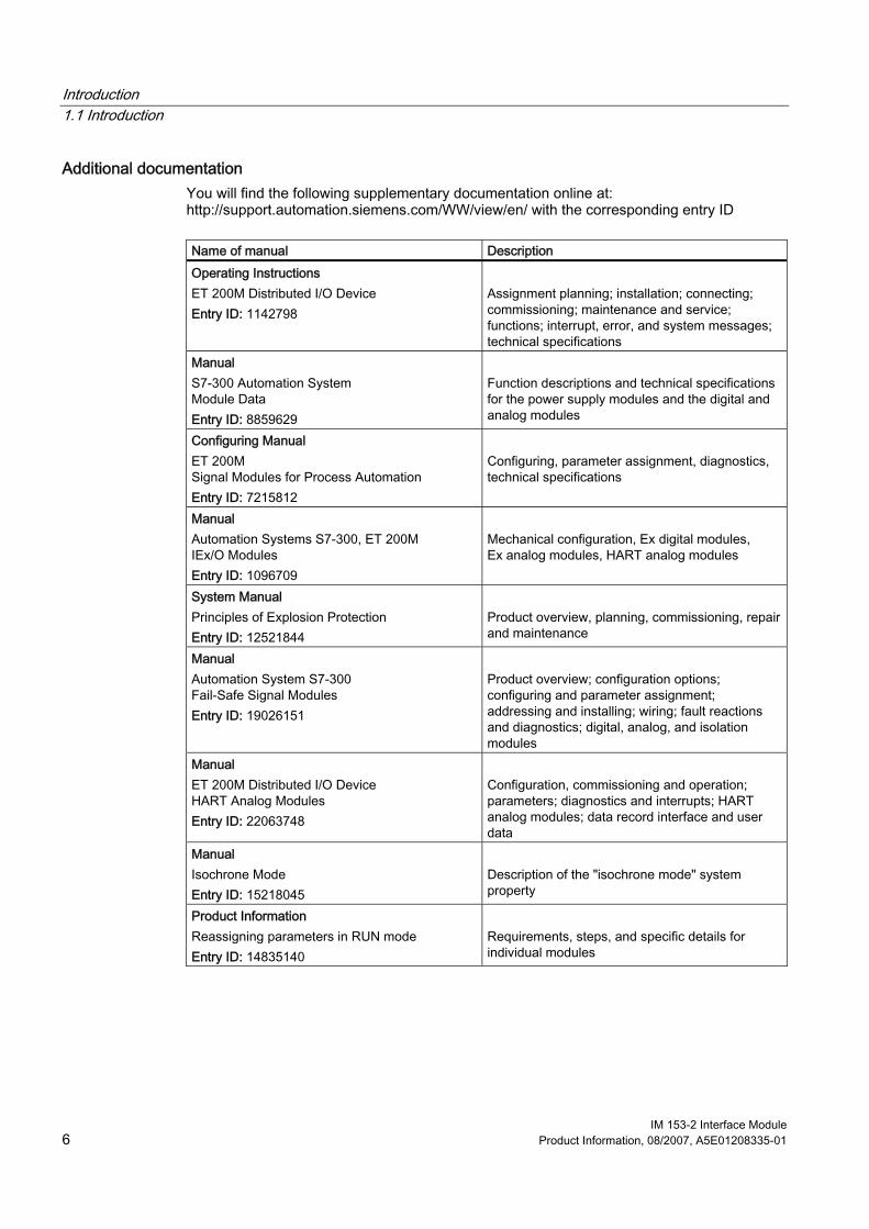
Introduction 1.1 Introduction
IM 153-2 Interface Module 6 Product Information, 08/2007, A5E01208335-01
Additional documentation You will find the following supplementary documentation online at: http://support.automation.siemens.com/WW/view/en/ with the corresponding entry ID
Name of manual Description Operating Instructions ET 200M Distributed I/O Device Entry ID: 1142798
Assignment planning; installation; connecting; commissioning; maintenance and service; functions; interrupt, error, and system messages; technical specifications
Manual S7-300 Automation System Module Data Entry ID: 8859629
Function descriptions and technical specifications for the power supply modules and the digital and analog modules
Configuring Manual ET 200M Signal Modules for Process Automation Entry ID: 7215812
Configuring, parameter assignment, diagnostics, technical specifications
Manual Automation Systems S7-300, ET 200M IEx/O Modules Entry ID: 1096709
Mechanical configuration, Ex digital modules, Ex analog modules, HART analog modules
System Manual Principles of Explosion Protection Entry ID: 12521844
Product overview, planning, commissioning, repair and maintenance
Manual Automation System S7-300 Fail-Safe Signal Modules Entry ID: 19026151
Product overview; configuration options; configuring and parameter assignment; addressing and installing; wiring; fault reactions and diagnostics; digital, analog, and isolation modules
Manual ET 200M Distributed I/O Device HART Analog Modules Entry ID: 22063748
Configuration, commissioning and operation; parameters; diagnostics and interrupts; HART analog modules; data record interface and user data
Manual Isochrone Mode Entry ID: 15218045
Description of the "isochrone mode" system property
Product Information Reassigning parameters in RUN mode Entry ID: 14835140
Requirements, steps, and specific details for individual modules
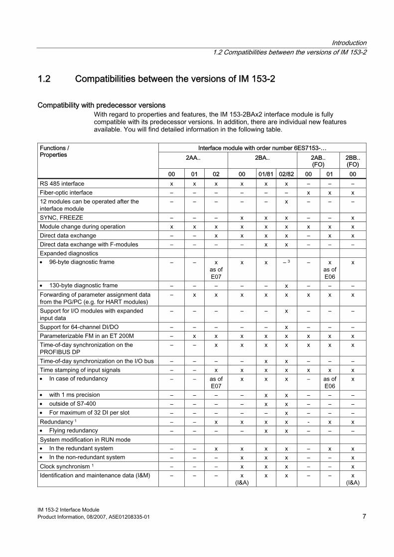
Introduction 1.2 Compatibilities between the versions of IM 153-2
IM 153-2 Interface Module Product Information, 08/2007, A5E01208335-01 7
1.2 Compatibilities between the versions of IM 153-2
Compatibility with predecessor versions With regard to properties and features, the IM 153-2BAx2 interface module is fully compatible with its predecessor versions. In addition, there are individual new features available. You will find detailed information in the following table.
Interface module with order number 6ES7153-…
2AA.. 2BA.. 2AB.. (FO)
2BB.. (FO)
Functions / Properties
00 01 02 00 01/81 02/82 00 01 00 RS 485 interface x x x x x x – – – Fiber-optic interface – – – – – – x x x 12 modules can be operated after the interface module
– – – – – x – – –
SYNC, FREEZE – – – x x x – – x Module change during operation x x x x x x x x x Direct data exchange – – x x x x – x x Direct data exchange with F-modules – – – – x x – – – Expanded diagnostics • 96-byte diagnostic frame – – x
as of E07
x x – 3 – x as of E06
x
• 130-byte diagnostic frame – – – – – x – – – Forwarding of parameter assignment data from the PG/PC (e.g. for HART modules)
– x x x x x x x x
Support for I/O modules with expanded input data
– – – – – x – – –
Support for 64-channel DI/DO – – – – – x – – – Parameterizable FM in an ET 200M – x x x x x x x x Time-of-day synchronization on the PROFIBUS DP
– – x x x x x x x
Time-of-day synchronization on the I/O bus – – – – x x – – – Time stamping of input signals – – x x x x x x x • In case of redundancy – – as of
E07 x x x – as of
E06 x
• with 1 ms precision – – – – x x – – – • outside of S7-400 – – – – x x – – – • For maximum of 32 DI per slot – – – – – x – – – Redundancy 1 – – x x x x - x x • Flying redundancy – – – – x x – – – System modification in RUN mode • In the redundant system – – x x x x – x x • In the non-redundant system – – – x x x – – x Clock synchronism 1 – – – x x x – – x Identification and maintenance data (I&M) – – – x
(I&A) x x – – x
(I&A)
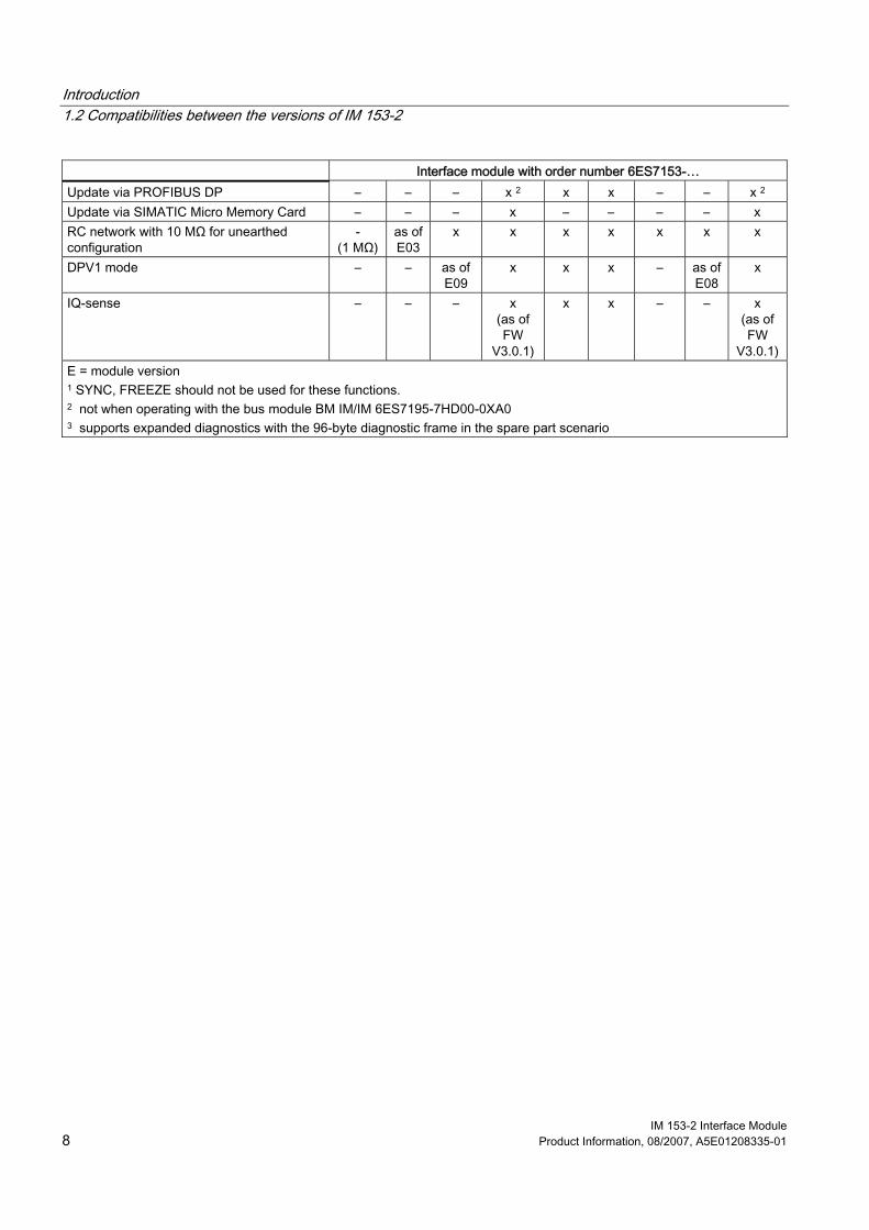
Introduction 1.2 Compatibilities between the versions of IM 153-2
IM 153-2 Interface Module 8 Product Information, 08/2007, A5E01208335-01
Interface module with order number 6ES7153-… Update via PROFIBUS DP – – – x 2 x x – – x 2 Update via SIMATIC Micro Memory Card – – – x – – – – x RC network with 10 MΩ for unearthed configuration
- (1 MΩ)
as of E03
x x x x x x x
DPV1 mode – – as of E09
x x x – as of E08
x
IQ-sense – – – x (as of FW
V3.0.1)
x x – – x (as of FW
V3.0.1) E = module version 1 SYNC, FREEZE should not be used for these functions. 2 not when operating with the bus module BM IM/IM 6ES7195-7HD00-0XA0 3 supports expanded diagnostics with the 96-byte diagnostic frame in the spare part scenario
IM 153-2 Interface Module Product Information, 08/2007, A5E01208335-01 9
Description 22.1 Increased module count
Module count A maximum of 12 modules can be operated with the IM 153-2BAx2 interface module, compared to 8 modules previously.
Configuration variants The following configuration variants are available for the IM 153-2BAx2 with up to 12 modules: ● Standard configuration with rail and bus connectors between the modules ● Configuration with active bus modules for the "Module change during operation" and/or
"Redundancy" functions The modules (up to a maximum of 12) are installed and connected according to the description in the ET 200M Distributed I/O Device ET 200M Operating Instructions.
Configuration The modules (up to a maximum of 12) are configured as usual: ● With STEP 7 V5.4 + SP 3 or later ● With a GSD file (SI04801E.GSG)
Restrictions Use of the high-accuracy time stamp (1 ms accuracy) is only possible with 8 modules. In this case, a maximum of 8 input modules can be inserted after the IM 153-2BAx2 interface module in the ET 200M.
2.2 Support for 64-channel DI/DO modules The IM 153-2BAx2 supports 64-channel DI/DO modules. For more detailed information, refer to the documentation on the respective modules. The 64-channel modules are configured the same as the other DI/DO modules.
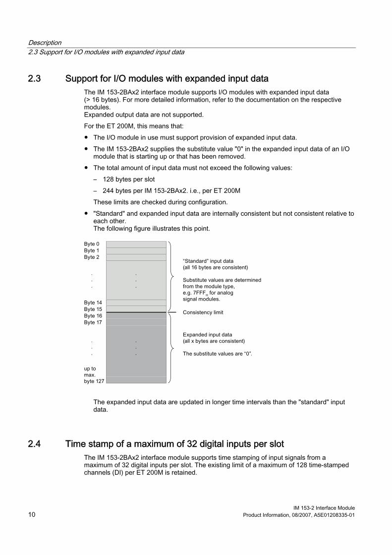
Description 2.3 Support for I/O modules with expanded input data
IM 153-2 Interface Module 10 Product Information, 08/2007, A5E01208335-01
2.3 Support for I/O modules with expanded input data The IM 153-2BAx2 interface module supports I/O modules with expanded input data (> 16 bytes). For more detailed information, refer to the documentation on the respective modules. Expanded output data are not supported. For the ET 200M, this means that: ● The I/O module in use must support provision of expanded input data. ● The IM 153-2BAx2 supplies the substitute value "0" in the expanded input data of an I/O
module that is starting up or that has been removed. ● The total amount of input data must not exceed the following values:
– 128 bytes per slot – 244 bytes per IM 153-2BAx2. i.e., per ET 200M These limits are checked during configuration.
● "Standard" and expanded input data are internally consistent but not consistent relative to each other. The following figure illustrates this point.
The expanded input data are updated in longer time intervals than the "standard" input data.
2.4 Time stamp of a maximum of 32 digital inputs per slot The IM 153-2BAx2 interface module supports time stamping of input signals from a maximum of 32 digital inputs per slot. The existing limit of a maximum of 128 time-stamped channels (DI) per ET 200M is retained.
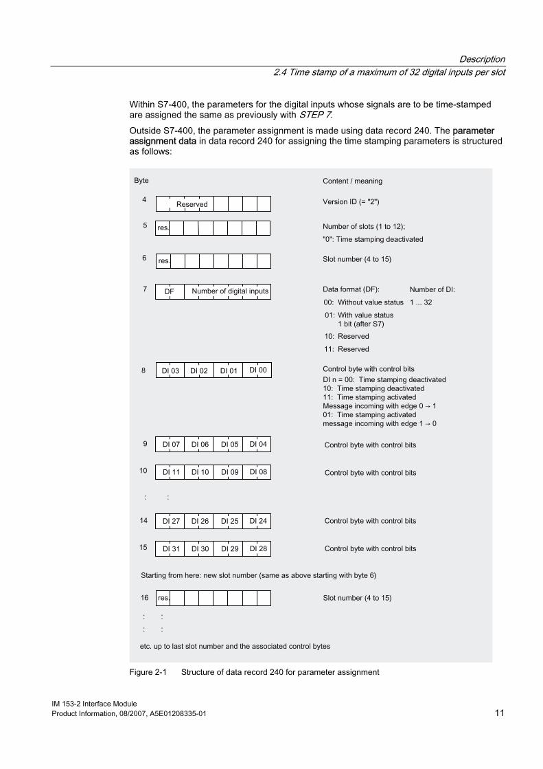
Description 2.4 Time stamp of a maximum of 32 digital inputs per slot
IM 153-2 Interface Module Product Information, 08/2007, A5E01208335-01 11
Within S7-400, the parameters for the digital inputs whose signals are to be time-stamped are assigned the same as previously with STEP 7. Outside S7-400, the parameter assignment is made using data record 240. The parameter assignment data in data record 240 for assigning the time stamping parameters is structured as follows:
Figure 2-1 Structure of data record 240 for parameter assignment

Description 2.5 Diagnostics with the IM 153-2BAx2
IM 153-2 Interface Module 12 Product Information, 08/2007, A5E01208335-01
2.5 Diagnostics with the IM 153-2BAx2 The IM 153-2 interface module (order number 6ES7153-2BAx2-0XB0 and higher) supplies the same diagnostic information as the existing IM 153-2 interface module. The maximum length of the diagnostics is now 130 bytes. Due to the 12 available slots, the IM 153-2BAx2 has a partially expanded diagnostic structure. In addition, the length of the diagnostic interrupt has been expanded. The following changes have been made in the diagnostics: ● The identifier-related diagnostic information comprises 3 bytes, same as previously.
Byte 8 contains an additional 4 bits for the new slots (slots 12 to 15). ● The module status is 1 byte longer and now comprises 8 bytes. Slots 12 to 15 now
contain 2 new bits each. ● The diagnostic interrupt can have a maximum of 63 bytes. For the meaning of the bits, refer to the ET 200M Distributed I/O Device Operating Instructions, Chapter Structure of the diagnosis.
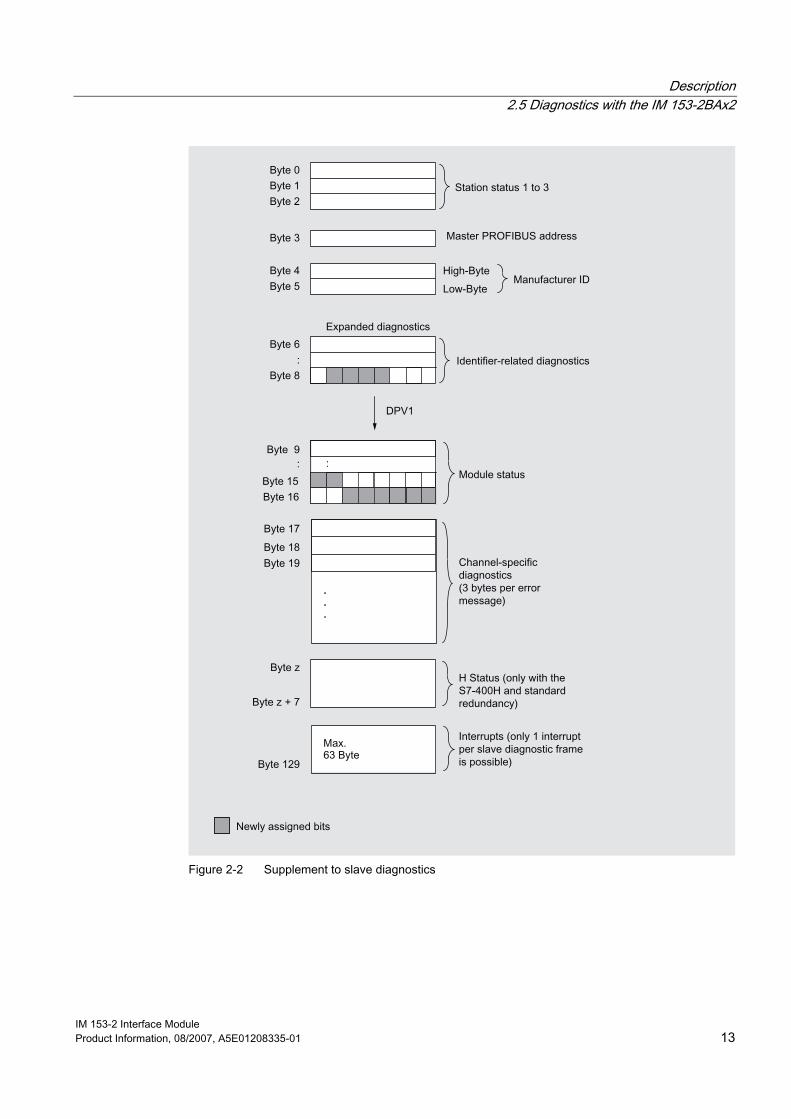
Description 2.5 Diagnostics with the IM 153-2BAx2
IM 153-2 Interface Module Product Information, 08/2007, A5E01208335-01 13
Figure 2-2 Supplement to slave diagnostics
Description 2.6 Parameter assignment/operation of HART field devices by means of PDM
IM 153-2 Interface Module 14 Product Information, 08/2007, A5E01208335-01
2.6 Parameter assignment/operation of HART field devices by means of PDM
Starting situation For the HART field devices, the following starting situation exists: ● The HART field devices are connected to HART input/output modules. ● The HART input/output modules are distributed among 12 slots of an ET 200M with
IM 153-2BAx2.
Parameter assignment/operation For the starting situation described above, the following requirements apply to parameter assignment/operation of HART field devices: ● EDD (for ET 200M) Version V1.1.8 or higher
EDD (Electronic Device Description) is required to set up HART field devices. It is included on the PDM Device Library CD (as of Edition 2, dated 2007) supplied with PDM.
● PDM V6.0 SP3
Note If an older PDM version is used together with the EDD indicated above, an error message is not issued. However, then HART field devices on HART input/output modules that plug into slots 12 to 15 cannot be operated.
2.7 Configuring with a GSD file
Note If you configure the ET 200M (IM 153-2BAx2) with a GSD file, the length of the parameter assignment frame (maximum 244 bytes) can lead to limitations in the number of assignable modules.
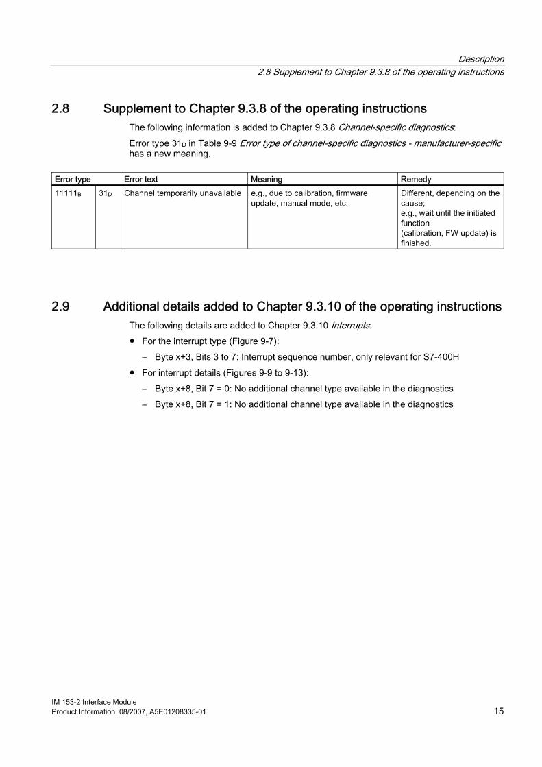
Description 2.8 Supplement to Chapter 9.3.8 of the operating instructions
IM 153-2 Interface Module Product Information, 08/2007, A5E01208335-01 15
2.8 Supplement to Chapter 9.3.8 of the operating instructions The following information is added to Chapter 9.3.8 Channel-specific diagnostics: Error type 31D in Table 9-9 Error type of channel-specific diagnostics - manufacturer-specific has a new meaning.
Error type Error text Meaning Remedy 11111B 31D Channel temporarily unavailable e.g., due to calibration, firmware
update, manual mode, etc. Different, depending on the cause; e.g., wait until the initiated function (calibration, FW update) is finished.
2.9 Additional details added to Chapter 9.3.10 of the operating instructions The following details are added to Chapter 9.3.10 Interrupts: ● For the interrupt type (Figure 9-7):
– Byte x+3, Bits 3 to 7: Interrupt sequence number, only relevant for S7-400H ● For interrupt details (Figures 9-9 to 9-13):
– Byte x+8, Bit 7 = 0: No additional channel type available in the diagnostics – Byte x+8, Bit 7 = 1: No additional channel type available in the diagnostics

Description 2.9 Additional details added to Chapter 9.3.10 of the operating instructions
IM 153-2 Interface Module 16 Product Information, 08/2007, A5E01208335-01
IM 153-2 Interface Module Product Information, 08/2007, A5E01208335-01 17
Technical specifications 33.1 Supplement to Chapter 10.1 of the operating instructions
The FM certification in Chapter 10.1 Standards and approvals is supplemented with the following warning notices:
WARNING Personal injury and material damage can be incurred. In potentially explosive environments, there is a risk of injury or damage if you disconnect any cable connections while the ET 200M is in operation. When operating the ET 200M in potentially explosive environments, make sure that it is deenergized before disconnecting the cable connections.
WARNING
Explosion hazard If components are swapped, the suitability for Class I, Div.2 can be become invalid.
WARNING
This device is only suitable for use in Class I, Div. 2, Group A, B, C, D or in non-potentially explosive areas.
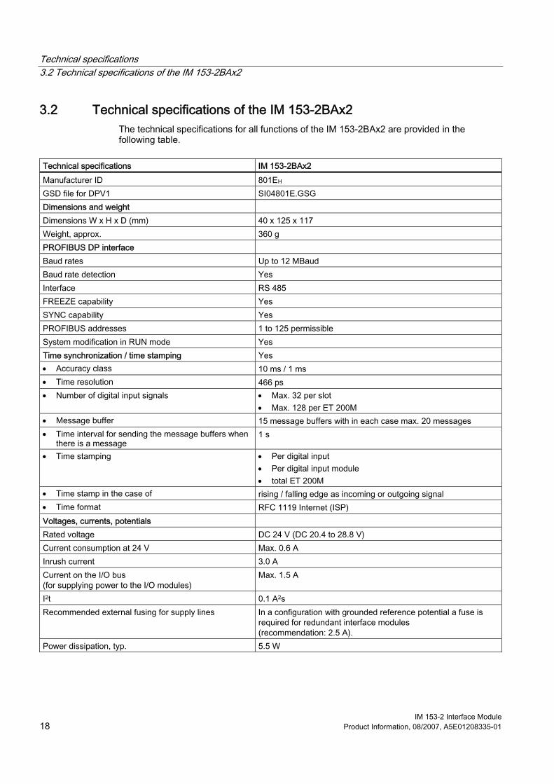
Technical specifications 3.2 Technical specifications of the IM 153-2BAx2
IM 153-2 Interface Module 18 Product Information, 08/2007, A5E01208335-01
3.2 Technical specifications of the IM 153-2BAx2 The technical specifications for all functions of the IM 153-2BAx2 are provided in the following table.
Technical specifications IM 153-2BAx2 Manufacturer ID 801EH GSD file for DPV1 SI04801E.GSG Dimensions and weight Dimensions W x H x D (mm) 40 x 125 x 117 Weight, approx. 360 g PROFIBUS DP interface Baud rates Up to 12 MBaud Baud rate detection Yes Interface RS 485 FREEZE capability Yes SYNC capability Yes PROFIBUS addresses 1 to 125 permissible System modification in RUN mode Yes Time synchronization / time stamping Yes • Accuracy class 10 ms / 1 ms • Time resolution 466 ps • Number of digital input signals • Max. 32 per slot
• Max. 128 per ET 200M • Message buffer 15 message buffers with in each case max. 20 messages • Time interval for sending the message buffers when
there is a message 1 s
• Time stamping • Per digital input • Per digital input module • total ET 200M
• Time stamp in the case of rising / falling edge as incoming or outgoing signal • Time format RFC 1119 Internet (ISP) Voltages, currents, potentials Rated voltage DC 24 V (DC 20.4 to 28.8 V) Current consumption at 24 V Max. 0.6 A Inrush current 3.0 A Current on the I/O bus (for supplying power to the I/O modules)
Max. 1.5 A
I2t 0.1 A2s Recommended external fusing for supply lines In a configuration with grounded reference potential a fuse is
required for redundant interface modules (recommendation: 2.5 A).
Power dissipation, typ. 5.5 W