distributed operational object mobilize (doom) · web viewthe distributed operational object...
TRANSCRIPT

Faculty of Science and Engineering
Distributed Operational Object Mobilizer (DOOM)Group 11
ENG 4000Presented to: Dr. Eshrat Arjomandi
April 30, 2007
Group Members:Amir Saeidi 207025653Derek Poon 205542162
Leo Chan 206850523Pierre Malavoy 206952030
Advisors:Professor JinJun Shan

Professor Minas SpetsakisAbstract
The Distributed Operational Object Mobilizer (DOOM) is a system that coordinates the movement of two mobility devices in order to lift an object in unison. The source of information necessary for the control of the devices is entirely provided by the analysis of overhead images taken of the object and mobility devices assembly. The analysis of these images yield relative position and orientation measurements of the devices with respect to the each other and the object. These, in turn, are processed to produce the appropriate commands to the mobility devices.
Figure 1: Mobility Devices Lift Object in Unison
DELIVERABLESOur final product consists of an overhead camera connected by cable to a laptop. The laptop contains the image processing software and C program used to issue commands to the mobility devices’ microcontrollers via the laptop’s serial port. The mobility devices in question consist of two ‘mobility devices’ using differential drive and a forklift device.
2

The system as a whole functions autonomously from the image acquisition phase to the positioning of the mobility devices and lifting of the object.
APPLICATIONSAutomated forklift systems are already being manufactured and used in commercial applications. Corecon is one such manufacturer producing Automated Guided Vehicles (AGV) of all kinds. Their automated forktruck, the Falcon F150, featured in the adjacent figure is lauded as a key component to the future of warehouse automation. The
Figure 2: Falcon F150 Forktruckadvantages of automation are many: human error is eliminated paving the way for an incident/accident free workplace; there would be a significant financial advantage in the long run due to an important increase in efficiency and a decrease in manpower.
The key difference between the current trend and our system is in the guidance system of the forklift. While current automated vehicles rely on sensors integral to each unit, our system’s operation is based on the image analysis of the entire situation: forklifts, payloads and
environment. This type of setup ensures cohesion among the multiple automated vehicles since their movements would all be controlled through a unique command system. The use of an overhead camera would also enable secondary applications such as security surveillance and the tracking of inventory in the warehouse.
The increase in efficiency offered by such a system would also translate into power consumption and therefore reduce an industry’s overall impact on the environment. Its autonomous nature would also undoubtedly produce a safer workplace.
3

Table of Contents
1 Abstract 11.1 Deliverables 12.1 Applications 2
Acknowledgments 6
2 Introduction 7
3 Technical Description 93.1 Image Analysis 9
3.1.1 Software 93.1.2 Trajectory Accuracy 10
3.1.3 High-Level Algorithm 10
3.1.4 Markers 103.2 System Control 12
3.2.1 Programming the Microcontroller 123.2.2 Control Algorithm 153.2.3 Servo Control and Operation 193.2.4 Bluetooth 21
3.4 Mobility Device 223.4.1 Microcontroller 223.4.2 Motor Controller 223.4.3 Gearbox and Motors 233.4.4 Wheels and Caster 233.4.5 Chassis and Proto-board 243.4.6 Power Supply 243.4.7 Forklift Mechanism 243.4.8 Circuit Design 25
4 Constraints 274.1 Operational Constraint 274.2 Heatlh, Environmental and Safety Constraints 27
5 Budget 27
6 Future Work 28
7 Conclusion 28
4

8 Bibliography 29
Table of Figures
Figure 1: Mobility Devices Lift Object in Unison 2
Figure 2: Falcon F150 Forktruck 3
Figure 3: Protocol Diagram 8
Figure 4: Image Analysis sequence 9
Figure 5: Mobility Device and Object Assembly 11
Figure 6: Mobility Device Angular Orientation 12
Figure 7: Servo Pulse Parameters 19
Figure 8: Servo Operation 19
Figure 9: Gear Rack 19
Figure 10: Fast PWM Mode Timing Diagram 20
Figure 11: Motor controller Setup 23
Figure 12: Chassis Modification 24
Figure 13: Forklift Mechanism 24
Figure 14: Mobility Device Circuit on Protoboard 25
Figure 15: Circuit Layout 26
Figure 16: List of Expenses 27
5

Acknowledgments
Ator Sarkisoff was extremely helpful in aiding us to implement our vision of the forklift mechanisms for both mobility devices
6

Introduction
The objective of our group project was to make two individually operated mobility units lift an object in unison based on positional information derived from an overhead image of the object and mobility devices. A camera was used to take the aerial snapshots. The analysis of these images determined the two positions around the object from which it is be lifted as well as the direction and relative position of the mobility devices with respect to these two positions.
There will be a need for image processing software that will perform the analysis on the image to retrieve the desired information. This program first isolates the object from its background and sets it in a coordinate system. Assuming that the density and thickness of the object is constant, its centre of gravity is determined. Using this measurement, two positions are calculated from which the object needs to be lifted to keep it balanced. Finally, the program correlates these positions with that of the mobility devices. To unambiguously identify each mobility device as well as their direction and relative position, they are fitted with visual markers that the image analysis program can manipulate. The mobility devices receive commands from connections to the RS232 port of the central control unit (laptop) and physically lift the object through a forklift device fitted to their front end.
Figure 2 shows the general protocol of the system. The camera sends images taken to the computer which analyzes it and processes the coordinates into commands. These commands are then sent to the mobility devices through the max232 chip that converts the serial signal into TTL for the microcontroller. The latter then implements the commands by operating both the servo through Pulse-Width Modulation (PWM) and the motors, through the motor controller, with a serial signal from its USART (Universal Synchronous/Asynchronous Receiver/Transmitter) port.
7

Computer
MAX232N
Camera
Microcontroller
Servo Motor Controller
Figure 3: Protocol Diagram
USB
RS232
USART
PWM USART
Device
Protocol
8

Technical Description
IMAGE ANALYSIS
SoftwareThe image analysis is performed with MATLAB (Matrix Laboratory). MATLAB comes with a variety of pre-defined functions that can be easily used to manipulate images. The software package implemented for Image Acquisition and Processing incorporatees the following functions:
cMass(bimage): Finds the Center of mass of ANY object given a binary image. The object can be regular or irregular, as long as it is a uniform shape. This function is written in a way that it can detect the Center of mass of multiple object within a binary image and then return coordinates as 2xN matrix (where n is the number of objects in the image).
fitCircle(image): Receives any image format (in our case RGB) converts it to binary and returns the radius of a fitted circle onto an object. This function was initially designed strictly for circular objects, but it can work as well with any other shape. The outcome for any shape is the best fitted circle onto the given image. This can be modified to perform for multiple shapes within an image.
ColourCode(bimage,image): Receives a binary and regular image, colour codes each image ranging from black to white (order is black=’0 0 0’, blue=’0 0 1’, green=’0 1 0’, red=’1 0 0’ and white ‘1 1 1’). This function was originally designed to colour code an image containing no more than 4 shapes but by adding hybrid colours we could colour code (Maximum 3 bits) up to 7 shapes. This can be done just as well with intensity, where we can have plenty more shapes coded within one image, but the initial idea was to use simple colours (i.e. white in our case).
A simple demo of our software is shown in the adjacent figure. This is a very basic program that acquires an image through a webcam and then, using an image subtraction algorithm, makes use of the pre-written functions such as the ones shown above. Following the isolation of the object, the cMass() function is used to obtain the coordinates of the
9
Figure 4: Image Analysis sequence

centre of mass of the object. This information is then passed onto the command algorithm which translates relative positions into commands to the mobility devices.
Trajectory AccuracyThe Logitech Quickcam used has a FPS of 30. The operating speed of the mobility devices, averaged over several test runs, is 5.01 cm/s (0.05 m/s), with an average error tolerance of 5mm/m traveled and an average travel distance of 1.5m . We then have:Total error = 1.5*(5) = 7.5 mmError Duration = 0.75/5=0.15 secondsSo in order of us to be able to keep the error tolerance at 5mm for every meter traveled we need to have an FPS of:FPS = 1/0.15 = 6.67 frames/sec ≈ 7 FPSAnd this is well within the hardware constraint for our imaging system (30 FPS). Also the average run time of 1 frame for the tested code has been estimated at 0.1 seconds (Maximum of 10 FPS), and our findings seem to give the software enough time to acquire and process the images with no real time shortage.
High-Level AlgorithmThe imaging software is able to perform the following in a short period of time:
Acquire the image Remove non reflective back-ground Locate the designated symbols (colour coded) Calculate the center of each symbol and draw a vector between the centers of
mass of two corresponding symbols Use this information to calculate the position as well as the orientation of each
mobility device, and compare it with the target points on the object to be lifted.
10

The following diagram should give a better impression of what the image processing software is “seeing” after removing the background and drawing the corresponding vectors:
Figure 5: Mobility Device and Object Assembly
Using this simple algorithm the central computer can process and calculate an updated trajectory for each frame taken. A few frames can be used for comparison only, just to check if the mobility device has followed the trajectory to within the average error tolerance, if not then the software interrupts the process and updates the mobility devices’ positions by sending out updated commands.
MarkersThe markers used for each mobility device are two circles of different size lined up along the central axis of the mobility devices. They are white in colour in order for the camera to easily dintinguish them from the black background. For the same reason, these circles are placed a black piece of bristle board that is just large enough to mask the mobility device from the camerea.
The rear side and the front side of the mobility devices are distinguished using the differential area method. The smaller (area wise) shape represents the front side of the mobility device. Distinguishing the difference between mobility device 1 and mobility device 2 is implemented by making both maker circles of one mobility device smaller than those of the other one.
11

SYSTEM CONTROL
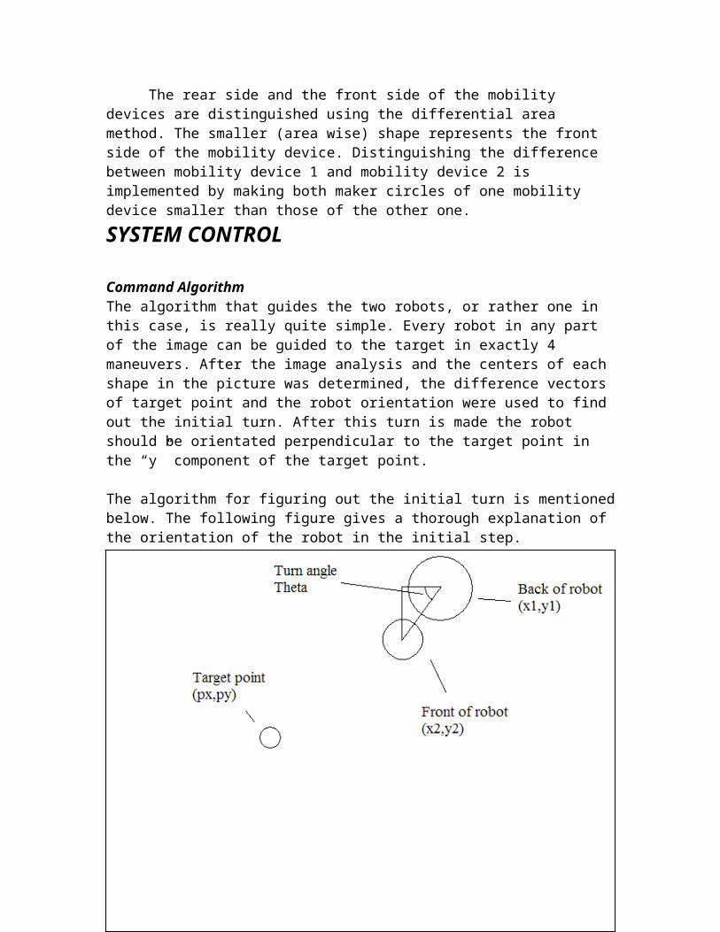
Command AlgorithmThe algorithm that guides the two robots, or rather one in this case, is really quite simple. Every robot in any part of the image can be guided to the target in exactly 4 maneuvers. After the image analysis and the centers of each shape in the picture was determined, the difference vectors of target point and the robot orientation were used to find out the initial turn. After this turn is made the robot should be orientated perpendicular to the target point in the “y” component of the target point.
The algorithm for figuring out the initial turn is mentioned below. The following figure gives a thorough explanation of the orientation of the robot in the initial step.
Figure 6: Mobility Device Angular Orientation
To figure out the turn angle the following code is used:
theta1=atan(-(y2-y1)/(x2-x1));
12

The reason –(y2-y1) is used is that in images the coordinate of each pixel is different than that of the conventional Cartesian coordinate system. The (Xmax,Ymax) point in this case are at the lower right side of the picture, rendering the Y-axis of the image equal to the negative Y-axis of the conventional coordinate system.To determine whether the robot needs to turn to the right or left at the start we need to visualize 4 separate quadrants in the image and using if-statements to check what the right maneuver is. We need to determine the orientation of the robot and then check for 2 test cases to see if a left or right turn is needed depending on wheter the mobility device eis above or below the object. The if-statement below shows the robot’s orientation (x-point in the 1st and 4th quadrant) and then checks if the robot is facing towards or away from the object.
if((x2-x1)>0) if(y1<py) thetat=theta1+(pi/2); t=thetat/omega t=round(t*666) turn('R',t,thetat,id); elseif(y1>py) thetat=(pi/2)-theta1; t=thetat/omega t=round(t*666) turn('L',t,thetat,id); end
Evaluation of each of the nested if-statements can cause the respective right or left turn to maneuver into a perpendicular manner, facing away from the object by 90 degrees. The next if-statement is followed by the one showed above that describes the maneuver in the 2nd and 3rd quadrant.
elseif((x2-x1)<0) if(y1<py) thetat=(pi/2)-theta1; t=thetat/omega t=round(t*666) turn('L',t,thetat,id); elseif(y1>py) thetat=theta1+(pi/2); t=thetat/omega t=round(t*666) turn('R',t,thetat,id); end The duration of the turn is determined by the rotational rate of the robot in pixel/sec which depends on the distance of the camera from the ring, as shown in the algorithm (t=thetat/omega)
13

The next maneuver involves bringing the robot as close as possible to the target point while reamining perpendicular to it. It is a simple forward movement that uses the constant robot velocity across the screen to find out the movement duration. Using v=d/t and knowing the average velocity of the robot we can figure out the movement duration.
d=abs((y1-(6.11*3))-py)t2=(d/(6.11))/(2)serialcon(id,'F',t2);theta2=pi/2t3=theta2/omegat3=round(t3*666)
After this step the robot should just need a 90 turn to completely face the target and then by a single forward movement the robot should be at the wanted point. The code of the 90 degree turn is very similar to that of the initial turn because there is a direction (left or right) determination problem. Again with the use of if-statement we can figure out the direction of the turn, but this time knowing the turn degree exactly.
if((x1-px)>0) if(y1<py) turn('R',t,theta2,id); elseif(y1>py) turn('L',t,theta2,id); end elseif((x1-px)<0) if(y1<py) turn('L',t,theta2,id); elseif(y1>py) turn('R',t,theta2,id); end end
After the 90 degree turn the robot is facing the target and with a simple forward movement now we can have out robot on the target. This part of the program is again very similar to that of the first forward movement.
d=abs((x1-(6.11*3))-px)t4=(d/(6.11))/(2)serialcon(id,'F',t4);
With the use of simple algebra we can guide each robot to the wanted point in the image with only 4 maneuvers.
14

Programming the MicrocontrollerFor this project, we used the program called AVR Studio 4 to implement the microcontroller unit (MCU). It is a professional Integrated Development Environment (IDE) for use with Atmel’s AVR microcontrollers. It is freely distributed by Atmel and can be downloaded from the Atmel website. AVR Studio 4 provides an assembler for both assemble and c language, chip simulator and in-circuit emulator interface. It also has the ability to simulate a predefined input pattern to the pins of any port at a specified clock cycle in a stimulus file. For example, a cycle number of 200 at port B will have the pattern of 01011011. We then put the following in the .sti file
000000001:00000000200:5B
XXXXXXXXX:XX.
999999999:FFA .sti file must end with this line
In order to connect the microcontroller with the motor controller and the computer’s serial port, we linked the two devices to the USART (Universal Synchronous/Asynchronous Receiver/Transmitter) ports on the microcontroller. The main feature of USART is to provide an Asynchronous serial reception or transmission operation at a given Baud Rate (bps). In our case we have set port USART0 on the MCU to receive signals from max232 serial conversion chip and port USART1 to transmit signals to the motor controller.
Before controlling the two motors on the motor controller, we had to define the motors and give each of them a unique identifier number. Configuration was achieved by sending a three byte packet consisting of the start byte, a configuration command byte and the new configuration byte:
Start Byte = 0x80 Change configuration =0x02 New Setting, 0x00-0x7F
In our project, we set the MC with the following 3 bytes:[0x80 | 0x02 | 0b010000000] ; 1-motor mode, controlling motor 0[0x80 | 0x02 | 0b010000001] ; 1-motor mode, controlling motor 1[0x80 | 0x02 | 0b000000010] ; 2-motor mode, controlling motor 0 and 1
The first two commands are already predefined in the motor controller and only the last command is sent to the motor controller to assign number two as the UID to control both motors at the same time.
In order to set the speed and direction of a motor, we send a four byte command as follow:
Start Byte = 0x80 Device type = 0x00
Motor # and direction
motor speed
At byte number three Bit0 is used to specify the direction of the motor. Setting it to 1 will make the motor go forward and 0 to go backward. Bits 1 – 6 specify the motor
15
number, in this case it is only between 0 – 2. Byte number four is used to set the speed of the motor. A value of 0 turns the motor off. The possible range of values is between 1 and 127 in DEC.Here is an example of setting the motor to full speed and then decelerating it until stop:
For k=1 to 127[0x80 | 0x00 | 0x05 | k ] ; In this loop the motor controller starts both motors (UID 2) at
the speed of 1 and goes up to 127For k=127 to 0[0x80 | 0x00 | 0x05 | k ] ; In this loop the motors start decelerating
To make a left or right turn, a command is sent to the microcontroller to make one motor run and the other stop.
[0x80 | 0x00 | 0x01 | k ] ;This will make a right turn[0x80 | 0x00 | 0x03 | k ] ;This will make a left turn
The most integral part of the MCU (microcontroller unit) programming depends on the interrupts which are actually provided by the MCU header files. Interrupts provide a “go to” event in which they trigger a certain function that would be executed every time a certain condition was met during the program cycle of the MCU.
In this project we made use of the USART flag for receiving serial signals. Since there is really no way of stopping the transmission of bytes in a one-way communication system, the MCU should throw an interrupt as soon as it receives a byte from the computer’s serial port.
As soon as the interrupt is thrown a function is called that is in charge of analyzing the incoming bytes.
Now before going anymore in depth into what the interrupt function does, we need to discuss the respective data packets sent to the robot each time.
The data format for each packet is as follows:
Start byte: 0x20 Device ID: 0x01 Byte 1: Maneuver Byte 2: Duration
So we have a start byte that flags the start of each data packet. Then we have a Device ID which defines which robot we are sending the signal to (1 or 2 for each robot). Byte 1 gives the movement’s nature which can include ‘F’ for forward, ‘L’ for left turn, ‘R for right turn and so on. Byte 2 gives the duration of the maneuver from Byte 1.
Here is the interrupt function used to flag the start and end of each data packet and direct the data into the right channels.
ISR(USART_RXC_vect) {
16

char rs232_data;rs232_data = UDR; // Read RX Data Reg. (Clears Int. Flag)
PORTA = rs232_data; // Debug Statement on Port Aif(rs232_data == ' '){
end=0;start=1;bytecounter++;
}else if(rs232_data=='1' && bytecounter==1)
bytecounter++;else if(bytecounter==2) {
Udata[0]=rs232_data;bytecounter++;
} else if(bytecounter==3){Udata[1]=rs232_data;bytecounter=0;end=1;
}
}
The 0x20 flags the start of the data packets and after that the next 3 bytes determine the parameter which robot, what maneuver and for how long. So now, we have to find a mechanism in which the MCU is constantly monitoring the end of each packet to find out when to actually execute the incoming signal.
The main program in the MCU looks like this:
int main(){
int speed=15;DDRA = 0xFF;
// Initialise USARTUSART_vInit();
//Initialize lifitng module (servo)initServo();
DDRD = _BV(PD4); /* enable output on port D, pin 4 */ PORTD = _BV(PD4); //Set PD4 to high to start using the
motor controller_delay_ms(250);while(1){
if(end==1){
17

if(Udata[0]=='F'||Udata[0]=='B'){Motor_Control(Udata[0], speed); delay(100*Udata[1]);Motor_Control(Udata[0], 0); //breakend=0; // Reset the end flag.
}else if(Udata[0]=='L'||Udata[0]=='R'){
Motor_Control(Udata[0], 10); delay(1.5*Udata[1]);Motor_Control(Udata[0], 0); //breakend=0; // Reset the end flag.
}else if(Udata[0]=='U'){
servoUP();end=0;
}else if(Udata[0]=='D'){
servoDown();end=0;
}}else;
}
return 0;}
As seen all the initializations are done in the beginning of the main program, such as the servos, USART communication and the speed of the robot.
When the end of each packet is reached the main program will evaluate the bytes 1 and 2 within that byte packet and execute the respective commands. The while(1) loop is an infinite one where the MCU will have to keep executing to monitor and execute the incoming commands.
It is imperative to mention that in order to be able to make use of any of the interrupts in the MCU, there is a need to initialize them first. This is done within the USART_vInit() function where the configuration bytes are set as follows:
// Enable transmitter and reciever UCSRB = _BV(RXEN) | _BV(TXEN) | _BV(RXCIE);sei();
Where UCSRB is the USART configuration register where we enable both transmission and reception of the signal and also the interrupt flag of RXCIE which is strictly linked to the reception of data.
18

Also the sei(); enables global interrupts with in the MCU program. So the ISR function is called as soon as a byte is received and as soon as the byte is received and analyzed the MCU will continue to execute the line where it was previously to the interrupt call.
Servo Control and OperationA signal wire is used to send a pulse that controls the angular position of the servo. The angular position is determined by the duration of the pulse. This is called Pulse Width Modulation. The parameters for this pulse are that it has a maximum pulse (2 milliseconds) width and a minimum pulse width (1ms) with a total period of 20ms.
Figure 7: Servo Pulse Parameters
Since we are using a 180 degrees rotation servo, we can see how the pulse width corresponds with the angular position as in the following figure:
Figure 8: Servo Operation
A 1.0 ms pulse will make the servo turn to 0 degree angular positionA 1.5 ms pulse will make the servo turn to 90 degrees angular positionA 2.0 ms pulse will make the servo turn to 180 degree angular position
Positioning CalculationWhen an external force is applied on the servo while the servo is holding its position, the servo will keep holding this same position and resist that force. However, it will not hold forever, the same position pulse must be repeatedly send to
19
Figure 9: Gear Rack

the servo to keep the servo at that specific position. The maximum external force the servo can resist is equal to the torque of the servo: 3.9 kg-cm in our case.
Since the servos must implement a forklift function, a gear rack attached to the spline of the servos convert its rotation into linear motion. We can then calculate the displacement of the gear rack with respect to the pulse width. The gear rack has 30 teeth every 2 inches and the servo has 48 teeth on the spline – 48 pitch. However, since the servo only rotates 180 degree instead of 360 degree, only half of the teeth on the spline are used. Which mean 24 teeth on the gear rack are being used as well. Therefore the maximum displacement (the maximum height an object can be lifted) is
mminch
mminch
toequalalsoinch
inchteethteeth
ntdisplacemeimum
64.40
4.256.1
6.1
23024max
According to our design of the forklift, the fork on the robots are supposed to lower to the ground, be inserted under the load and then lifted up. The highest position will be 0 degree which correspond to 1ms pulse width. Hence, we can calculate the appropriate pulse width for the displacement of lowering the fork to the ground. According to the measurement we need to lower forklift by 20.30mm to reach the ground,then the pulse width will be:
)deg90(50.1
00.164.4030.20
reems
msmmmm
widthpulse
Therefore, we need to send a pulse width of 1.50 ms within a period of 20ms to lower the forklift, then send a pulse width of 1.00 ms to lift up the object and hold it at this position by sending the same pulse width continuously. Hence in the program, the up or down operations of the servo are written as functions where servoDown() has a duty cycle of 1.5ms and servoUP() has a duty cycle of 2.0ms.
The waveform generator works under fast Pulse Width Modulation Mode where a counter counts from BOTTOM to TOP then restarts from BOTTOM to calculate the period of the waveform. Since we have manually
20
Figure 10: Fast PWM Mode Timing Diagram

defined the clock in the microcontroller to be 1Mhz, every clock cycle has a period ofs6101 .
sMhz
frequenceperiod
61011
1
1
Therefore, we need 20000 cycles to reach the top. The Output Compare (OC1A), which is the waveform, is initially set to 1. It is set to clear (set to 0) if a compare match exists between TCNT1 and OCR1A, where OCR1A is the duty cycle of the pulse
BluetoothWe had a lot of trouble using the Bluetooth as an interface between the computer and robots. The first problem we encountered was that when we called the LocalDevice.getLocalDevice() function to locate the Bluetooth device, it actually returned "localhost" which is not our Bluetooth Adapter. Secondly, in our design, we were supposed to have a Bluetooth device to communicate with the computer, but we had problems reading from the Bluetooth serial port on the robot side. We tried to write to a C++ application that read files generated by Matlab to give commands to the robots and sent under the Windows platform. The application sends data perfectly, but the robot side did not receive data at all.
21

MOBILITY DEVICES
The mobility devices were designed and constructed for minimal size and weight while still being amply able to perform the desired tasks. These tasks consist of mobility, including differential drive and the ability to ‘turn on a dime’, as well as forklift capability. The components of the mobility devices are describes in the following subsections followed by a description of the circuit layout.
MicrocontrollerThe Atmel Atmega32 was used as the microcontroller for each mobility device. It is a high performance low power 8-bit microcontroller. It can achieve up to 16 Million instructions per second (16 MIPS) and its in-system programmable flash memory can endure 10,000 write/erase cycles which is a must for a project like this one in which the MCU’s program will be reworked and the memories reprogrammed. The microcontroller has 32 programmable Input/Output lines including two Universal Serial Asynchronous Receiver and Transmitter (USART) ports that are used to connect to the max232 chip (or Bluetooth), to receive the serial signals from the serial port of the laptop, as well as send the necessary signals to the motor controller. Atmel’s AVR MCU line also has the advantage of having access to free development software: Atmel’s AVR Studio.
Motor ControllerThe motor controller acts as an H-bridge, controlling the operation of the motors through the serial signal received from the microcontroller. The motor controller selected is the Pololu low-voltage dual serial motor controller. It is very compact in size; about the size of a quarter. The setup scheme is shown in the following figure. The Atmega32 microcontroller is shown here as the Robot Controller. The motor controller is connected to the power supply to provide the motors with their supply voltage during operation. It has pin-out connections to the MCU for ground, logic supply voltage (5V), reset and serial control input. The reset connection will be kept on high logic (5V) during operation. Putting the port to low (0V) temporarily resets the motor controller: Sets motors off and waits for serial signal. The serial connection (OUT1) is connected to one of the USART ports of the microcontroller mentioned earlier. It is through this connection that the motor controller’s H-bridge circuit is controlled to operate the motors as directed by the serial signal.
22

Figure 11: Motor controller Setup
Gearbox and MotorsThe mobility devices’ gearbox and motor assembly is the Tamiya Double Gearbox assembly. It is a well known and reliable system. The double gearbox model is an offshoot of the very popular twin gearbox model that is widely used in amateur mobility devices and children’s toys. The newer model features thicker gears for added robustness and four possible gear ratios instead of two. A gear ratio of 115:1 was chosen for our application as it offers a perfect combination of torque and speed. With a wheel diameter of 58 mm and a maximum efficiency motor speed of 9100 r/min, the maximum theoretical speed of the mobility devices will be 24 cm/s. This seems quite high, but the actual maximum operating speed of the device is significantly lower mainly due to efficiency lost through the many gear reductions. The two motors are very compact, low current F130 DC motors.
Wheels and CasterThe mobility device runs on two wheels with a diameter of 58 mm. A Pololu caster serves as the third point of contact. The wheels are Tamiya narrow tires that are built specifically for precise movement: They are constructed solid (little deformation) and rounded with a very small point of contact with the ground surface to allow turns with
23
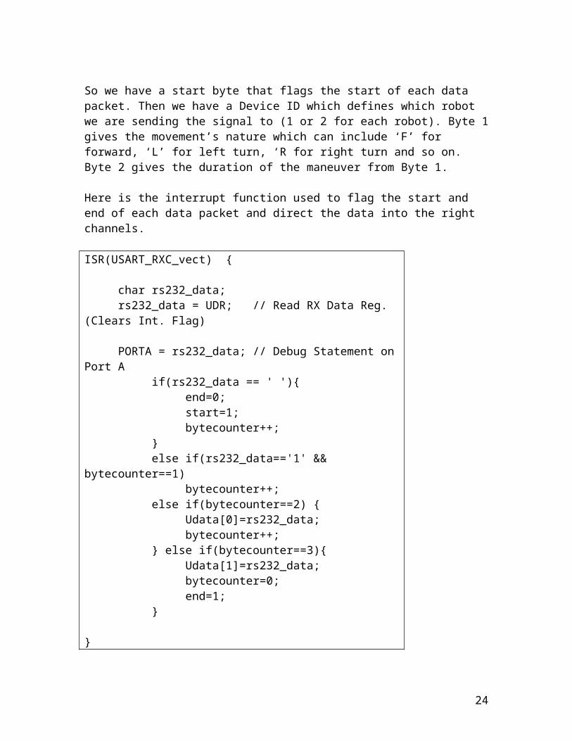
Figure 12: Chassis Modification
minimal friction. The caster is positioned at the back of the mobility device to allow the gearbox and power pack to cancel out each other’s moment about the wheels’ spin axis.
Chassis and Proto-boardThe chassis is made of sturdy and lightweight acrylic. It is compatible with the gearbox assembly selected and has a variety of slots to attach additional components, such as the forklift mechanism and caster. It is a compact 5 inches in diameter. The sides were carefully cut with an exacto knife to fit the wheels we selected. This alteration can be seen in the figure on the right.
The proto-board is an add-on to the chassis and serves as the circuit breadboard to all the onboard electronics: MCU, motor controller and Bluetooth transceiver. It has the same dimensions as the chassis and is fixed to the latter by four 1.25 inch standoffs.
Power SupplyThe power supply is provided by four 1.5V C Batteries (alkaline) housed in a battery pack. The leads to the pack were soldered to the protoboard and provided power for logic voltage as well as for motor and servo operation. The weight of the power pack also allowed it to act as a counterweight of sorts to offset the weight of the gearbox under the chassis as well as that of the object being lifted.
Forklift MechanismThe forklift operation is performed by a servo motor through a custom built forklift design. The servo motor is the Hitec HS-225BB Mighty Mini. Its maximum torque of 3.9
kg-cm is large for its size which is desirable for our application to overcome the friction forces present in the movement of the forklift mechanism. Below is a schematic showing the design of the forklift. The forklift mechanisms consists of plexiglass guide rails fastened to the robot chassis, a copper palette with a 48 pitch gear rack and a servo equipped with a 48 pitch gear. The rotational motion of the servo gear in translated into the desired linear motion of the palette through its interaction with the gear rack. The system was designed for minimal weight, through the use of lightweight materials.
24
Figure 13: Forklift Mechanism

CIRCUIT DESIGN AND OPERATION
The circuit components were positioned and soldered onto the proto-board of each mobility devices as can be seen in the following figure. The two sets of channels running horizontal on the proto-board were used as a common access point to both positive voltage and ground. The power supply is passed to a first switch which controls the logic voltage supplied to the microcontroller and motor controller, through a 5V voltage regulator in the middle of the proto-board. The second switch controls the supply of unregulated 6V power to the motor controllers motor power supply input.
Figure 14: Mobility Device Circuit on Protoboard
The corresponding schematic of the protoboard circuit layout is shown in the following figure. It conveys a clearer picture of the flow of powre through the system. Also noticeable are the Atmega32 ports used for the implementation of the device. The Vcc, ground and reset ports are standard for all uses of this microcontroller. The reset port is kept on high by connecting it to Vcc through a 10 kiloOhm resistor. The serial motor
25

controller signal is transmitted through port 15 which implements the USART Transmitter function, and sent to the serial input port of this latter. Port 18 was kept on high (1) and fed to the motor controller’s reset port in order to keep it high. Finally, the servo pulse signal was outputted through port 19 which implements PWM.
Figure 15: Circuit Layout
26

Constraints
OPERATIONAL CONSTRAINTSIn its most general form our mission objective is quite complex, see implausible. To arrive at a realistic and workable objective, we have deemed it necessary to impose certain restrictions. As stated previously, the thickness and density of the object to be lifted is assumed to be uniform throughout. The possible shapes of the object are also of great importance. We are initially proposing to limit the shape to that of a simple polygon. The position accuracies achievable will be limited by the camera resolution and hardware components accessible to us within our constrained budget.
HEALTH, ENVIRONMENTAL AND SAFETY CONSTRAINTSThere was not much impact on our project in terms of health, environmental and safety constraints. Our system as a whole consumes very little power and did not utilize any hazardous materials.
Budget
The details of the budget changed considerably throughout the course of this project. These changes were either caused by the replacement of low quality equipment, broken parts, a change in the overall design, or the omission of necessary parts.
The first microcontroller we purchased was an atmega128 development board from microcontrollershop.com. After several days of unsuccessfully trying to program it, we finally diagnosed that the part was faulty and decided to proceed on a different course with a more reliable manufacturer. This led us to purchase the atmega32 from digikey. Further costs were incurred when we accidentally burned out various chips while developing the mobility devices. We ended up having to replace 3 microcontrollers and a motor controller.
We were able to find a camera adequate for our application at a lower price than we had anticipated, but this was offset by the cost of miscellaneous parts such as various screws, wires and other tools.
Figure : List of Expenses
Component CostCamera (Webcam) $ 57
27

MOBILITY DEVICE: JTAG USB Dongle $60 Mk II Dongle $40 Atmega128 Development Board $40 Atmega32 Microcontroller x3 $25 Max232 IC $2 Motor Controller $63 Gearbox and Motors Servo Motor $33 Resistors and Capacitors $15 2 Drive Wheels and Caster $20 Battery Pack $31 Chassis and Proto-board $25 Bluetooth Receiver and Transmitter $150 Miscellaneous (Screws & nuts, wires, etc.) $25 Shipping, Handling and Customs $130Total Per Mobility device $559x2 1118Grand TOTAL $1275
Future Work
The most obvious course of action would be to successfully incorporate Bluetooth into our system in order to make the mobility devices wireless. We learned that Bluetooth was a project of its own. Although we gained a lot of experience and knowledge of the communication standard, we could not implement it in time for the demo. With a little more time, this aspect of the project would be completed.
In terms of money, our system could be made bigger and more importantly more precise. Since our entire system relies on the information derived from images, a vastly superior camera would enable us to achieve impressive accuracy in terms of the commands issued to the devices. The devices themselves left a lot to be desired. The motors and gearboxes are the components which would be replaced first. Again, this relates to the accuracy of their operation.
Conclusion
This project achieved what it sought to in its initial conception. We were able to construct a system that can function autonomously in guiding two mobility devices to the
28

appropriate coordinates to lift an object. The development of the image analysis and command algorithm was done to the limit of precision possible for the camera being used. The mobility devices were a successful implementation of a compact and lightweight mobility device, with forklift capability, that we had envisioned.
Bibliography
Textbooks:
Valvano, Jonathan W., Embedded microcomputer systems : real time interfacing, Thomson, Southbank, Victoria, Australia, 2007
Bräunl, Thomas, Embedded robotics : mobile robot design and applications with embedded systems, Springer-Verlag, Berlin, 2006
Websites:
Nicola Asuni - Circuits, Pinouts, Hardware Guideshttp://www.technick.net/public/code/cp_dpage.php?aiocp_dp=_main
Society of Robotshttp://www.societyofrobots.com/
AVR Freakshttp://www.avrfreaks.net/
Manuals:
Atmel Atmega32 Datasheethttp://www.atmel.com/dyn/resources/prod_documents/doc2503.pdf
Pololu dual low-voltage serial motor controller User’s Guidehttp://www.pololu.com/products/pololu/0120/smc05a_guide.pdf
FA-130 Mabuchi Motor Datasheethttp://www.pololu.com/products/tamiya/fa_130ra.pdf
29