distribution i* dwense prch &wibuaudrchch … · amorcer le processus de conception en...
TRANSCRIPT

UNLIMITED DISTRIBUTION
I* National Defence DWense National.PR"ch &WiBuaudRchchDmveopnwnt Branch tDvlpmn
TECHNICAL COMMUNICATION 88/302qNovember 1988
00 _
0
IaUSERS MANUAL FOR THE SHOP5 SYSTEM:
A Concept Exploration Model forMonohull Frigates and Destroyers
J. L Colwell
Defence Centre doResearch Recherches pour laEstablishment D6fense DTICAtlantic AtlantiqueT
DEC 2 71988
Canadif HDZSTR it ON STATEMNT A
Approved fo publC relea8e- 0Distibtion Undmlted 8 12 4
. .......... ..... 1 i l l il l i ~

UNLIMITED DISTRIBUTION
I , lNational Defence Defense nationaleResearch and Bureau de rechercheDevelonent Branch et d~veloppement
USERS MANUAL FOR THE SHOP5 SYSTEM:A Concept Exploration Model forMonohull Frigates and Destroyers
James L. Colwell
November 1988
Approved by W. C..E. Nethercote H / Hydronautics Section
DISTRIBUTION APPROVED BY .4
D/7O
TECHNICAL COMMUNICATION 88/302
Defence C Centre deResearch Recherches pour laEstablishment DWense
Atlantic Atlantique
Canadi

ABSTRACT
The SHOP5 System is a computer-aided ship design tool for monohull frigate and destroyerConcept Exploration. Its primary application is initializing the new-ship design process bydetermining the ship size, hull form and major systems best suited for the design require-ments. Other uses include evaluating new technologies and performing specific parametricstudies. The SHOP5 System incorporates three FORTRAN programs in a closed-loopsystem: program FIVPRE for defining and modifying ship descriptions and design re-quirements; program SHOP5 for computing ship characteristics; and program FIVPOS forexamining design candidates using computer graphics. Design calculations include seakeep-ing in head seas, resistance, powering and range in calm water and in waves, propulsionand electrical system modeling, distribution of weight and volume components, preliminaryintact and damaged stability analysis, and platform acquisition cost. Platform feasibility isassessed by user-definable design criteria which define goals for performance and capability.The SHOP5 ship description and design methodology are sufficiently flexible to define andanalyse a wide variety of ship geometries, systems and missions.
R1 SUM-
Le syst~me SHOP5 est un outil de conception assist6e par ordinateu, permettant ie con-cevoir des modiles de frigates et destroyers monocoques. Son utilit6 principale consiste hamorcer le processus de conception en d6terminant la taille du biteau, la forme de la coqueet les principaux systimes qui conviennent le mieux en fonction des exigences. Le syst~mesert aussi i 6valuer les nouvelles technologies et A rdaliser l'analyse de certains pararntresparticuliers. Le syst~me SHOP5 est constitute de trois programmes FORTRAN qui fontpartie d'une boucle: le programme FIVPRE sert A definer et . modifier les descriptions etles exigences de calcul; le programme SHOP5 sert A determiner les characteristiques d'unnavire; et le programme FIVPOS sert & 6valuer les candidats en conception au moyen del'infographie. Les calculs de conception tiennent compte de facteurs comme la tenue en merhouleuse, la r6sistance, le ddmarrage et le rangement en eaux calmes et dans les vagues,la mod6lisation de la propulsion et du syst6me 6lectrique, la distribution du poids et duvolume des composants, l'analyse pr6liminiare de la stabilit4 en 6tat intact ou endommag6et le cofit d'acquisition de la plate-forme. La faisabiliti de la plate-forme est analyse Apartir de critres de calcul que l'utilisateur peut choisir et qui d6finissent les buts en termesde performance et de capacite. La mthodologie de description et de calcul de SHOP5 estsuffisamment souple pour ddfinir et analyser une vaste gamme de ggom~tries de bateaux,de systimes et de missions.
iii

Contents
ABSTRACT ii
NOTATION v
1 Introduction 1
2 Concept Exploration: Traditional vs Contemporary 2
3 Overview of the SHOP5 System 33.1 Integrated SHOP5 System ............................ 3
3.2 M odes of Operation ............................... 4
4 SHOP5 Input 44.1 Ship Description ................................. 5 4
4.1.1 Optional Input ... ... .. ... ... ... ... .. ... ... .. 54.1.2 Method Control Integers, MCI ..................... 6
4.2 Design Requirements ............................... 6
4.3 Design Criteria .. ... .. ... ..... ... ..... ... ... ... .. 8
5 Overview of Design Methodology 95.1 Balancing Weight and Volume Components .................. 105.2 Defining Total Enclosed Volume ........................ 115.3 SHOP5 Lim its ........................ .......... 125.4 Dependence on Contemporary Practice ..................... 125.5 Using Cost as a Comparative Parameter .................... 135.6 Design M argins .... ... ... ..... .. ... .... .. . .. ... .. 14
6 SH-OP5 Output 15 6
7 Design Optimization: An Example 167 1 Design Philosophy ................................ 16
7.2 Example Design Requirements ......................... 177.3 Other Constraints and Decisions ........................... 177.4 Starting the SHOP5 Design Process ...................... 18
7.4.1 The First Input File: SEARCH Mode ................. 187.4.2 The First Run ......................... ..... 19
7.5 Defining the "Optimum" Design Candidate ....................... 20
iii

8 Other uses for the SHOPS System 23
9 Concluding Remarks 24
FIGURES 27
APPENDICES 33A: SHOP5 Input Records..................................... 33B: Optional Input Parameters.................................. 48
C: Design Optimization Example, Session I......................... 53D: Design Optimization Example, Session 2......................... 70E: FIVPOS Parameters...................................... 85
REFERENCES 88
iv

NOTATION
Names in typewriter font and in square brackets, [... , define lineprinter notation.
AccHi RMS vertical acceleration for zero percent crew effectiveness
AccLo RMS vertical acceleration for one-hundred percent crew effectiveness
AccMax seakeeping criterion, maximum vertical acceleration at station 4, -az
AK cost factor
AP after perpendicular =_ station 20
AM midship sectional area
avPgen average ship service electrical power generated
Aw waterplane area
B maximum beam [B]
C compartment standard of flooding (for damaged stability)
Ca model-ship correlation allowance (resistance)
CApp coefficient of appendage resistance, CApp = RApp/pS V 2 [Capp]
CB block coefficient, CB = V/L B T [Cb]
CM midship section coefficient, CM = A.k/ B T = CB/ CP
CODAD engine configuration; combined diesel and diesel
CODAG engine configuration; combined diesel and gas turbine
CODOG engine configuration; combined diesel or gas turbine
COGAG engine configuration; combined gas turbine and gas turbine
COGOG engine configuration; combined gas turbine or gas turbine
Cp prismatic coefficient, Cp = V/AmL jCp)
CPP controllable pitch propeller
CrM Froude length/displacement ratio, ( = L/V-
Cw waterplane coefficient, Cw = AwIL B (Cv]
DIAM propeller diameter
D midship hull depth [D]
DENS hull material density, Phw,
DISP full load displacement, A
Detruc structural hull depth (keel to strength deck)
dPE design margin on effective power, PE = PE(1 + dPE) [dPe]
dWi margin for weight component i
V

dWb margin on Wh.",, used for future growth margin
dVi margin for volume component i
dVhu11 special parameter for reducing SHOP5 estimate of hull volume
e tra jsport effectiveness e = W .,,bet/A IIecrew crew seakeeping effectiveness
ecrew(min) seakeeping criterion, minimum ec,e, [EffMin]
EffMin seakeeping criterion, minimum ecre,
Ffp freeboard at forward perpendicular
Fmod factor on midship sectional modulus
FRB minimum midship freeboard for reserve buoyancy
Fa,m most probable maximum slam force
Falam(i az) seakeeping criterion, maximum Fj.am [SimMax]
g gravitational acceleration, 9.807 m/sec2 (32.174 ft/sec2 )
GM r metacentric height (solid) [GM]
g.t. gas turbine
Hw significant waveheight, seakeeping [Hw]
Hw r) significant waveheight, powering and range
IGEN MCI for ship service electrical generators
IAPPND MCI for appendage resistance calculations
ICOST MCI for cost factors
IENGIN MCI for propulsion system configuration
IPROP MCI for type of propeller
IRESID MCI for residuary resistance databases
ISTRUC MCI for structural materials
IVOLUM MCI for sizing superstructure
ITTC International Towing Tank Conference
KG vertical centre of gravity
KGb KG for dWb
KGc KG for Wcombat
KG,n.. design criterion, maximum intact KG [KGmax]
L ship length between perpendiculars ILI
LCB longitudinal centre of buoyancy
vi
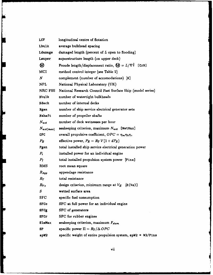
LCF longitudinal centre of flotation
Lbulk average bulkhead spacing
Ldamage damaged length (percent of L open to flooding)
Lauper superstructure length (on upper deck)
0 Froude length/displacement ratio, @= L/V' [CrM]
MCI method control integer (see Table 2)
N complement (number of accomodations) [N]
NPL National Physical Laboratory (UK)
NRC FSS National Research Council Fast Surface Ship (model series)
Nbulk number of watertight bulkheads
Ndeck number of internal decks
Ngen number of ship service electrical generator sets
Nshaft number of propeller shafts
N.et number of deck wetnesses per hour
N,t(,,z) seakeeping criterion, maximum Nwet (WetMax]
OPC overall propulsive coefficient, OPC = IWm'h t7o
PE effective power, PE = RT V(1 + dPE)
Pgen total installed ship service electrical generation power
PA installed power for an individual engine
P, total installed propulsion system power [Pins]
RMS root mean square
RApr appendage resistance
RT total resistance
Rve design criterion, minimum range at VE [R(Ve)]
S wetted surface area
SFC specific fuel consumption
SFCo SFC at full power for an individual engine
sFCg SFC of generators
SFCr SFC for rubber engines
S1mMax seakeeping criterion, maximum F.a.
SP specific power H = RT/A OPC
spW2 specific weight of entire propulsion system, spW2 - W2/Pins
vii
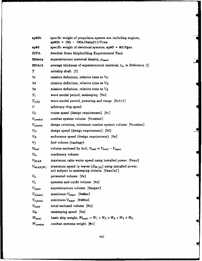
spW2b specific weight of propulsion system not including engines,spW2b - (W2 - (W2a)Nshaft)/Pins
spW3 specific weight of electrical systems, spW3 - W3/Pgen
SSPA Swedish State Shipbuilding Experimental Tank
SSdena superstructure material density, Pauper
SSthck average thickness of superstructure material, t1 c in Reference [1]
T midship draft [T]
Tc mission definition, relative time at Vc
Td mission definition, relative time at VD
Te mission definition, relative time at VE
T. wave modal period, seakeeping [To]
To(R) wave modal period, powering and range [To r)]
V arbitrary ship speed
VC cruise speed (design requirement) [Vc]
Vcombat combat system volume [Vcombat)
V:(.i.) design criterion, minimum combat system volume [Vcombat]
VD design speed (design requirement) [Vd]
VE endurance speed (design requirement) [Ve]
Vf fuel volume (tankage)
VhWI volume enclosed by hull, VhIu = Vgotai - V,.pe,
Vm machinery volume
VMAX maximum calm water speed using installed power [Vmax]
VMAx(W) maximum speed in waves (Hw(R)) using installed power,not subject to seakeeping criteria [Vmax(w)]
V. personnel volume [Vn]
V. systems and outfit volume [Vo]
VOUPer superstructure volume [Vsuper]
Va(maz) maximum Vupe, [VsMax
V.(, .) minimum Vp,, [VaMin]
Vtt.1 total enclosed volume [Vt]
Vw seakeeping speed [Vw]
Wbasi basic ship weight, Wb..i, = WI + W2 + WS + WS + W6
Wombat combat systems weight [Wc]
viii

Wd disposable loads weight (Wd]
WetMax seakeeping criterion, maximum N.,t
W! fuel weight W! = A - (W ao€ + Wco,?at + Wd) [Wf]
W, structure weight Iwo
W2 propulsion system weight, W2 = W2. + W2b [W2]
W2. weight of propulsion engines, includes acoustic isolation module [W2a]
Wb weight of gearing, shafting, intakes and exhaust, etc. [W2b]
Ws ship service electrical system weight IW33
WS auxiliary systems weight (W5]
W6 outfit and furnishings weight [We]
YIELD hull material yield strength, Oryidd
i. maximum RMS vertical acceleration at station 4 [AccMax]
$ platform acquisition cost
A full load displacement (DISP]
17h qualified hull efficiency, 17h = 17r(1 - 1(l- w)
17M machinery efficiency
r, relative rotative efficiency
170 propeller open water efficiency
V displaced volume, V = Alp
II specific power fl = RT/A OPC [SP]
a0yeld hull material yield strength [YIELD]
p water density
Phut hull material density [DENS]
Pauper superstructure material density [SSdens]
ix

1 Introduction
The SHOP5 System is a computer-aided ship design tool for monohull frigate and destroyerConcept Exploration. Its primary application is initializing the new-ship design processby determining the size, hull form and major systems of the ship or ships best suited fora particular mission. Other applications include evaluating the effects of new technologiesand design requirements on ship characteristics, and performing parametric or comparativestudies of a more specific nature.
The SHOP5 System consists of three FORTRAN programs which are arranged to allowrapid definition and analysis of many possible design candidates. Program FIVPRE is aninteractive pre-processor for defining and modifying input, program SHOP5 is a stand-alone (batch) program for analysing the ship or ships defined by FIVPRE, and programFIVPOS is an interactive graphics post-Tirocessor for comparing design candidates generatedby SHOPS.
SHOP5 calculates a variety of ship characteristics, including: deck wetness, verticalaccelerations and slam force in head seas; resistance, powering and range in calm water andwaves; propulsion and ship service electrical generation systems modeling and performance;ship weight and volume components; intact and damaged stability; and platform acquisitioncost. The platform acquisition cost does not include any combat system or life-cycle costs,and is not sufficiently detailed for budgetary purposes; however, it is a useful, comparativeparameter for performing design trade-offs. Platform feasibility is assessed by compar-ing ship characteristics with a variety of user-definable design requirements and criteria,including: combat system weight and volume; operational speeds and range; acceptablelimits for seakeeping response parameters; and other criteria for structural integrity andstatic stability.
The SHOP5 ship description and design methodology are sufficiently flexible to defineand analyse a wide variety of ship geometries, systems and missions. Most input parametershave pre-programmed, default values representative of contemporary NATO practice, anda variety of internal methods are available for many design calculations. All default valuesand most calculations can be modified or replaced by user-supplied input. Thus, the SHOP5user should be familiar with the options for program input and have sufficient knowledge ofthe SHOP5 methodology to determine when default values and methods should be replacedby user-supplied input.
This Technical Communication describes the SHOP5 System operation, input and out-put. A brief summary of the traditional and contemporary design processes highlights somekey problems which are overcome by the SHOP5 System, without sacrificing the desirableaspects of traditional design. The SHOP5 System structure and modes of operation are dis-cussed and all input parameters are described. An overview of the SHOP5 design methodol-ogy summarizes important topics, including: the methods used to obtain a "balanced" ship;the dependence of SHOP5 calculations on contemporary practice; the comparative natureof the SHOP5 platform acquisition cost; and, the definition and usage of design margins.The SHOP5 System output structure is described, with emphasis on features for reducingthe amount of program output which must be examined. Finally, the primary applicationfor the SHOP5 System is illustrated by an example of design optimization, followed by a
I

brief discussion of other applications. The SHOP5 System technology base is documentedin Reference 1.
2 Concept Exploration: Traditional vs Contemporary
The traditional design process can be illustrated as a spiral, as shown in Figure 1 [2]'.The process begins by selecting a "basis ship", which is an existing ship whose capabilitiesclosely match those required for the new design. The design progresses through threeconceptual phases: Exploration, Development and Validation. Each phase considers thesame general aspects of design, illustrated by the radial components in Figure 1, but thetransition between design phases represents an increase in the level of detail and accuracyof both the ship description and design analysis. The primary goal of Concept Explorationis to initialize Concept Development by determining the ship size, hull form and majorsystems required to satisfy the design requirements. The end-product of this preliminarydesign process is the contract design, which defines the ship in sufficient detail to accuratelyestimate acquisition and operating costs, and to develop construction plans.
In the traditional context, the Concept Exploration phase is used to obtain the bestvariant of the basis ship for the current design requirements. This approach has a number ofsignificant advantages: it has produced a long history of successful designs; it permits veryrapid transition to the Concept Development phase; and it generally produces new designswhose performance is at least as good as the basis ship. On the other hand, there aresignificant problems associated with this process: it is often difficult to select an appropriatebasis ship, especially when new systems or requirements are considered; there is no assuranceof an "optimum" or "cost-effective" result, as the selection of a basis ship narrows the fieldof design possibilities at the very start of the design process; and, it constrains innovation.
The Concept Exploration Model (CEM), first reported in Reference 2, offers a solutionto the problems associated with the traditional design process, while retaining its advan-tages. A CEM is a computer-based design tool which assists the naval architect in theearliest phase of ship design. A CEM separates the general design process into two func-tional stages; design synthesis and design analysis. Design synthesis is performed by thenaval architect in defining ship geometry and systems for input to the CEM, and designanalysis is performed by the CEM.
When using a CEM, the contemporary design process is essentially the same as thetraditional process, with one major difference; the requirement to select a basis ship toinitiate the process is eliminated. This does not mean that the capability to use a basis shiphas been removed, rather, it is not required. The methods used by a CEM are sufficientlygeneral to consider a wide range of design options, with reasonable confidence in the results.Since a basis ship is not required, the designer can consider a much larger field of possibledesign candidates, and since a CEM is a flexible design tool, the designer can employ awide variety of contemporary, new, and anticipated future technologies. Also, a CEM caneasily model existing ships, for direct comparison of new design candidates with establishedperformance.
Inumerals enclosed in square brackets denote references
2

The basis ship still plays an important role in contemporary design. The characteristicsof existing ships provide valuable guidance for defining initial CEM input, and many of thedetails required for the Concept Development ship description must be based on existingships. A CEM allows the designer to select the best basis ship for Concept Developmentor to create a "hybrid" basis ship by combining systems from existing ships. Alternately, aCEM allows the designer to compare and/or combine contemporary and new technologies.
Another important difference in Concept Exploration between the traditional and con-temporary design processes is the relative importance of seakeeping analysis. In the tradi-tional process, seakeeping is the last step of design analysis, while in a CEM, seakeepinganalysis is the first step after defining ship geometry. Of course, reliable seakeeping analysismethods have only been available for a relatively short time, but when first introduced,they were not given high priority. Thus, although the capability for meaningful seakeepinganalysis has existed, it has not been an integral part of the design process. The shift inemphasis of seakeeping analysis is due to the realization that ships optimized for calm waterperformance often do not perform adequately in the typical, open-ocean environment.
The final difference between traditional and contemporary design considered here is therecent introduction of new platform types, including: SWATH ships; hydrofoils; SurfaceEffect Ships (SES); and, Air Cushion Vehicles (ACV). The Concept Exploration phasenow has two major functions: first, to determine the platform type best suited to thedesign requirements; and then, to determine the ship size, hull form and major systemsfor input to the Concept Development phase. The traditional design process, with itsdependence on a basis ship, cannot easily cope with different platform types. Indeed,using the traditional design process for new platform types forces the designer to enter theConcept Development level of design detail before a reasonable number of alternatives canbe explored. For contemporary design, the CEM must be either sufficiently flexible to modelall relevant platform types, or there must be more than one kind of CEM. At DREA, thelatter approach has been used, resulting in a family of CEM's for different platform types,including; SWATH [3], hydrofoil [4], and SES/ACV [5].
3 Overview of the SHOP5 System
The name SHOP5 stands for "SHip OPtimization, version 5"; however, it is important toappreciate that SHOP5 has no in-built optimization procedures. The design logic used inSHOP5 is relatively simple; given ship size, hull form, major systems and design require-ments, SHOP5 calculates performance and capability. Optimization is an iterative andcomparative process controlled by the user, as described in following sections.
3.1 Integrated SHOP5 System
The SHOP5 System is arranged to permit the rapid definition, analysis and inspection ofmany possible design candidates. A schematic view of the three SHOP5 System componentsis shown in Figure 2, where:
FIVPRE is an interactive pre-processor for defining and modifying ship descriptionsand design requirements for input to SHOP5;
3

* SHOP5 is a stand-alone (batch) program for analysing the ships defined by FIVPRE;and
* FIVPOS is an interactive graphics post-processor for inspecting ships output fromSHOP5.
These three components are integrated into a closed-loop, user-friendly system whichallows the designer to define ship descriptions, analyse their characteristics, inspect feasibledesign candidates, and then create new ship descriptions based on previous results.
3.2 Modes of Operation
SHOP5 has two modes of operation; SEARCH and DESCRIBE. The SEARCH mode allowsthe designer to define up to 800 ships for a single execution of SHOP5. As SHOP5 pro-ceeds through its design calculations (analagous to traveling around the design spiral), thecharacteristics of each ship are compared with the design requirements and other criteria,and ships which do not satisfy these constraints are rejected. The characteristics of feasibleships are transferred to FIVPOS, where the designer uses computer graphics to inspect andcompare the design candidates.
The DESCRIBE mode is different from the SEARCH mode in three respects: it onlyconsiders up to 11 individual ships; it does not reject ships; and it performs more detailedcalculations for some design steps. The DESCRIBE mode is used to to obtain more de-tailed output for individual ships and to model existing ships for comparison with designcandidates generated by SHOP5. Also, it may be used to examine ships rejected in theSEARCH mode.
The term "closed-loop system" refers to the data flow from program FIVPOS to pro-gram FIVPRE. When using FIVPOS to examine design candidates generated by SHOP5 inthe SEARCH mode, the user can select up to eleven ships for transfer to FIVPRE, wherethey are automatically inserted in a new DESCRIBE mode file. The user can immediatelyrun SHOP5 using this file or, more often, use this file as a basis for a new SEARCH modefile.
4 SHOP5 Input
SHOP5 input consists of the ship description, design requirements, design criteria, andcontrols for design methodology. The ship description defines ship size, hull form, topsidegeometry, and major systems. The design requirements define the combat system and oper-ational speeds, and for the SEARCH mode, the design criteria define goals for performanceand capability. The controls for design methodology allow the designer to select options forthe method used for particular design calculations, and to configure major ship systems.
With the SHOP5 System, program FIVPRE [6] is used to define all input. FIVPREcan be used in either a menu- or command-driven mode, and provides a comprehensiveon-line help facility. The example on design optimization presented in Section 7 describesmany of the features available in FIVPRE.
4
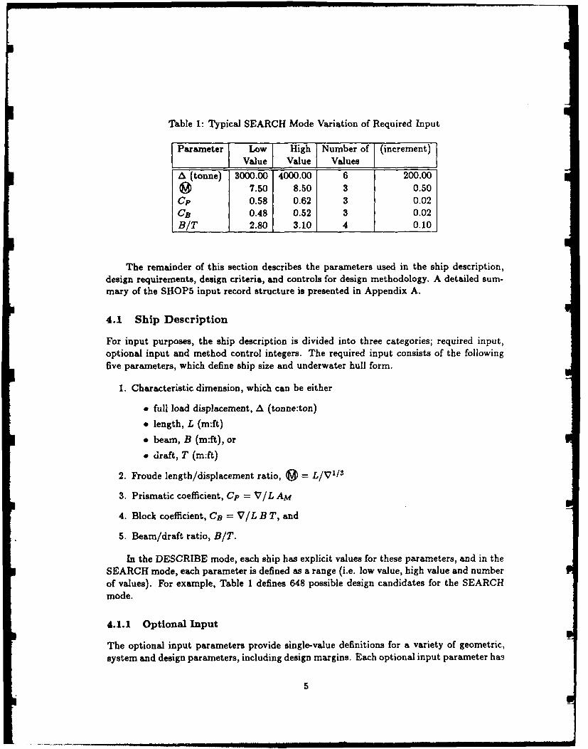
Table 1: Typical SEARCH Mode Variation of Required Input
Parameter Low High Number of (increment)Value Value Values
A (tonne) 3000.00 4000.00 6 200.00
7.50 8.50 3 0.50Cp 0.58 0.62 3 0.02CB 0.48 0.52 3 0.02BIT 2.80 3.10 4 0.10
The remainder of this section describes the parameters used in the ship description,design requirements, design criteria, and controls for design methodology. A detailed sum-mary of the SHOP5 input record structure is presented in Appendix A.
4.1 Ship Description
For input purposes, the ship description is divided into three categories; required input,optional input and method control integers. The required input consists of the followingfive parameters, which define ship size and underwater hull form.
1. Characteristic dimension, which can be either
" full load displacement, A (tonne:ton)
" length, L (m:ft)
" beam, B (m:ft), or
draft, T (m:ft)
2. Froude length/displacement ratio, (0 = L/V1 / 3
3. Prismatic coefficient, Cp = V/L AM
4. Block coefficient, CB = V/L B T, and
5. Beam/draft ratio, BIT.
In the DESCRIBE mode, each ship has explicit values for these parameters, and in theSEARCH mode, each parameter is defined as a range (i.e. low value, high value and numberof values). For example, Table 1 defines 648 possible design candidates for the SEARCHmode.
4.1.1 Optional Input
The optional input parameters provide single-value definitions for a variety of geometric,
system and design parameters, including design margins. Each optional input parameter has
5

a pre-programmed, default value or method which is representative of contemporary NATOpractice. The designer can define replacement values for any or all of these parameters;otherwise, the defaults are used. Appendix B describes these optional input parameters,including their default values and options for user-supplied input. Details on the algorithmsfor calculating the optional input default values are provided in Reference 1.
Program FIVPRE allows the user to access each optional input parameter individually(command mode), or via a multi-level menu system.
4.1.2 Method Control Integers, MCI
The method control integers (MCI) control options for the SHOP5 design methodology andconfigure major systems or arrangement parameters, as shown in Table 2. The MCI's aresimilar to the optional input parameters, except they define items which have a substantialimpact on the design methodology. Also, most MCI's accept variable amounts of user-supplied input to replace their default methods. In Table 2, the SHOP5 default methodsare shown for values of 0 (zero), which are used unless explicitly redefined by user-suppliedinput. Program FIVPRE allows the user to change the MCI values individually or viaa menu system. Five MCI's are directly associated with the ship description; ISTRUC,IPROP, IENGIN, IGEN, and IVOLUM. The applicability of the other MCI's for residuaryresistance, appendage resistance and cost factors must be evaluated in terms of the shipdescription. Reference 1 describes the resistance and cost algorithms and defines theirrequirements for user-defined input.
4.2 Design Requirements
The design requirements are required input which define the following parameters:
" combat system weight, W,., bt
" design speed, VD
" cruise speed, Vc
" endurance speed, VE
" seakeeping speed, Vw
" seakeeping significant wave height, Hw
The combat system weight includes all weapons, sensors, electronics, ammunition andaviation items, including aviation fuel. For new-ship design, the combat system is usuallyspecified as part of the design requirements. When this information is not known, then asuitable value for Wc.,,bat can be determined by examining existing ships. Alternately, anumber of W,6b values can be considered, by defining multiple sets of design requirements(different only in W,.,, ,t) and sequentially generating design candidates for each set ofrequirements. The combat system volume is considered as a design criterion, as explainedin later sections.
6

Table 2: Method Control Integers, MCI.
NAME VALUE DESCRIPTIONIDIMEN 0 full load displacement, A (tonne:ton)Characteristic Dimension 1 length between perpendiculars, L (m:ft)
2 maximum beam, B (m:ft)3 midship draft, T (m:ft)
IRESID 0 NRC FSSResiduary Resistance 1 Taylor, Hamburg C, or NPL/SSPAIAPPND 0 SHOP5 method (assumed appendages)Appendage Resistance I user-defined resistance coefficientIPROP 0 SHOP5 method, controllable pitchPropulsive Efficiency 1 SHOP5 method, fixed pitch
2 user-defined 0 PC valuesISTRUC 0 homogeneousStructural Material 1 hybridIENGIN 0 SHOP5 rubber enginesPropulsion System 1 user-defined rubber engines
2 SHOP5 real engines3 user-defined real engines
IGEN 0 SHOP5 diesel generatorsElectrical Generation 1 SHOP5 gas turbine generators
2 user-defined generators___________________ 3 integrated (propulsion system)
IVOLUM 0 Vobt= fI(Vouper)Superstructure Volume 1 VauPer = f (Vcomjat)
2 V~p, = f (URIB)ICOST 0 SHOP5 methodCost Factors 1 user-defined cost coefficients
7
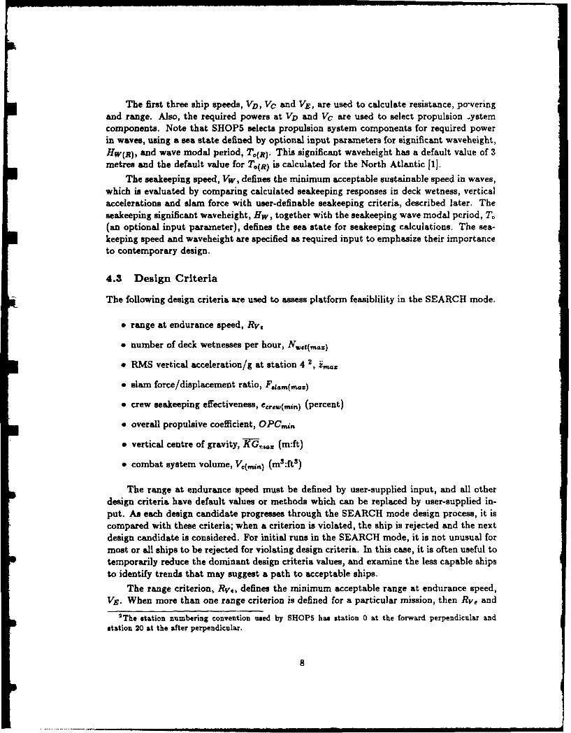
The first three ship speeds, VD, Vc and VE, are used to calculate resistance, poweringand range. Also, the required powers at VD and VC are used to select propulsion ystemcomponents. Note that SHOP5 selects propulsion system components for required powerin waves, using a sea state defined by optional input parameters for significant waveheight,HW(R), and wave modal period, To(?). This significant waveheight has a default value of 3metres and the default value for T(R) is calculated for the North Atlantic [1].
The seakeeping speed, Vw, defines the minimum acceptable sustainable speed in waves,which is evaluated by comparing calculated seakeeping responses in deck wetness, verticalaccelerations and slam force with user-definable seakeeping criteria, described later. Theseakeeping significant waveheight, Hw, together with the seakeeping wave modal period, T.(an optional input parameter), defines the sea state for seakeeping calculations. The sea-keeping speed and waveheight are specified as required input to emphasize their importanceto contemporary design.
4.3 Design Criteria
The following design criteria are used to assess platform feasiblility in the SEARCH mode.
" range at endurance speed, RV.
* number of deck wetnesses per hour, Nwet(maz)
" RMS vertical acceleration/g at station 4 2, z,
* slam force/displacement ratio, Fsgam(,mz)
" crew seakeeping effectiveness, ccrew(min) (percent)
" overall propulsive coefficient, OPCM,
" vertical centre of gravity, KG, ,,, (m:ft)
* combat system volume, Vc(,in ) (m3 :ft s )
The range at endurance speed must be defined by user-supplied input, and all otherdesign criteria have default values or methods which can be replaced by user-supplied in-put. As each design candidate progresses through the SEARCH mode design process, it iscompared with these criteria; when a criterion is violated, the ship is rejected and the nextdesign candidate is considered. For initial runs in the SEARCH mode, it is not unusual formost or all ships to be rejected for violating design criteria. In this case, it is often useful totemporarily reduce the dominant design criteria values, and examine the less capable shipsto identify trends that may suggest a path to acceptable ships.
The range criterion, Rw., defines the minimum acceptable range at endurance speed,Vy. When more than one range criterion is defined for a particular mission, then Rve and
2 The station numbering convention used by SHOPS has station 0 at the forward perpendicular andstation 20 at the after perpendicular.
8

VE should model the condition most likely to be dominant, and other range criteria can berapidly assessed using the computer graphics available in program FIVPOS.
The four seakeeping criteria are used in both the SEARCH and DESCRIBE modes.Their default values are, respectively, 60 deck wetnesses per hour, 0.20 gravities, 0.20 forthe slam force/displacement ratio, and 50 percent for crew effectiveness. In the SEARCHmode, the seakeeping behaviour of each design candidate is evaluated for the seakeepingspeed and significant waveheight (design requirements), and when a seakeeping criterion isviolated, the ship is rejected. In the DESCRIBE mode, SHOP5 calculates the ship speedat which each criterion is violated.
The design criterion OPCmn is evaluated at endurance speed, and provides a conve-nient method for early rejection of ships with very low propulsive efficiency. The defaultvalue for OPCi,, is 0.60 (60 percent).
By default, the design criterion KG,, is the maximum, intact transverse verticalcentre of gravity for positive stability in the damaged condition. This parameter can beredefined by user-supplied input as either a fixed value or as a fraction of midship hulldepth (i.e. KG,.. = 10 (m) or - ID = 0.60). When a ship's intact KG exceedsKG,, ., the ship is rejected. Another rejection criterion is the minimum midship freeboardfor reserve buoyancy in the damaged condition, FRB. This criterion is not listed above,as it cannot be re-defined by the user. The damaged condition is defined by the standardof compartmentation, C, which is an optional input parameter with a default value of3 (i.e. three adjacent compartments flooded). This parameter can be redefined by user-supplied input as either the number of compartments flooded or as a fraction of ship lengthopen to flooding.
The minimum acceptable combat system volume, , has a default value equal to12.5 percent of total enclosed volume (i.e. Vc(,,u,)/V.totl = 0.125). Since this parameter isof major importance and varies dramatically with mission and combat system components,it is recommended that user-supplied input be provided for ) whenever possible.
Finally, three conditions can lead to rejected ships in both the SEARCH and DE-SCRIBE modes.
" The derived midship coefficient (CM = AM/B T = CB/Cp) is outside the allowablerange for the residuary resistance database.
" The calculated thrust loading coefficient (see Reference 1) is outside the allowablerange for the propeller open water database.
" An internal or user-supplied real-engine database cannot produce an adequate propul-sion system, which usually indicates that the design speed power requirements exceedthe capability of the systems available.
5 Overview of Design Methodology
For each ship, the following calculations are performed sequentially.
* geometry
9

" seakeeping
" resistance, propulsive efficiency and required power
" propulsion system selection and performance
" ship service electrical generation system performance
" total enclosed volume
" weight components
" range
" stability
" volume components
" platform acquisition cost
The "arrangements" and "structure" design steps shown in Figure 1 are not included -
above, as they are not considered in sufficient detail to warrant separate status. In SHOP5,arrangements are considered in two stages: the ship description defines geometry and majorsystem configurations; and the weight, volume, and stability algorithms contain empiricalrelations based on contemporary NATO frigates and destroyers. The key arrangement pa-rameter calculated by SHOP5 is the combat system volume, V,, nt. This parameter is ameasure of the internal space available for combat systems; however, the actual arrange-ment of spaces is not considered. Similarly, key structural geometries are defined by theship description, and the algorithm for structural weight, W1, incorporates criteria for lon-gitudinal strength and minimum material thicknesses; otherwise, structures per se are notconsidered.
5.1 Balancing Weight and Volume Components
One of the most important aspects of the SHOP5 design process is the method used toachieve a "balanced" design. Ship weight components are balanced by the definition of fuelweight, Wf.
Wf = A-(WI+W 2 +WS+W+W+Wd+Wwmbt)
where A is the full load displacement, W, is structural weight, W2 is the propulsion systemweight, W3 is electrical systems weight, W5 is auxiliary systems weight, W6 is outfit andfurnishings weight, Wd is the disposable loads weight, and Wco,,at is the combat systemweight.
The full load displacement is defined by the ship description and combat system weightis defined as a design requirement; the remaining weight components are estimated usingempirical methods described in Reference 1. The fuel weight is a major factor in determiningrange, which is used as a design criterion in the SEARCH mode; any ships with insufficient
10

range at endurance speed are rejected. SHOP5 estimates W1 for eleven existing NATOfrigates and destroyers to within a maximum error of 3.2 percent of displacement (averageof 0.2 percent, standard deviation of 2.2 percent). More details are presented in Reference 1,including a tabular summary of estimating errors for all weight components.
Similarly, the balance of volume components is achieved by the definition of combatsystem volume, V, ,t.
Vc.o.t = VtV- W, + Vo + V, + Vf)
where Vtij is the total enclosed volume, V, is machinery volume, V, is outfit and systemsvolume, V,, is personnel volume, and V1 is fuel volume.
The total enclosed volume, Vott, is defined by the ship description and other volumecomponents are estimated using methods discussed in Reference 1. Thus, the combat systemvolume is the sum of spaces not required for any other ship functions. In the SEARCH mode,V, ,. is compared with the user-definable minimum acceptable combat system volume,V,(,M,); all ships with insufficient V,,b are rejected. SHOP5 estimates V,#.t for elevenexisting NATO frigates and destroyers to within a maximum error of 3.2 percent of Vtaj(average of 0.5 percent, standard deviation of 1.9 percent). More details are presented inReference 1, including a tabular summary of estimating errors for all volume components.
5.2 Defining Total Enclosed Volume
The total enclosed volume is separated into two components, hull volume, VhWU, and super-structure volume, .
Vttl=Vhull + Vaupe,.
For an individual ship, Vhul is defined by underwater and topside geometries, and soit is fixed by the ship description; however, there are three options for determining VeUpe
(controlled by method control integer IVOLUM, see Table 2).
1. Viper is fixed (defined by optional input parameter Vsuper )
2. Vjpe,. is sized to suit a target value for VcoLt
3. Vup, is sized to suit a target value for the metacentric height/beam ratio, GM/B
For the last two options, user-definable minimum and maximum superstructure volumesconstrain the variation of Y..p.. In both cases, the minimum superstructure volume servesas a starting point for determining the required V,,p, to satisfy the goal for Vcom, t orUM&/B. In the SEARCH mode, ships are rejected when they cannot satisfy the targetvalue for V,, &t or GM/B within the allowable variation of Vup,,. Reference 1 describesthese options in more detail.
The designer must exercise caution when using the SEARCH mode, as SHOP5 onlyconsiders volume, not deck area. Since the SHOP5 default method for defining midship
11

Table 3: Global Limits on Displacement and Hull Form Coefficients
Displacement, A- 2000 to 10,000 tonnesLength/displacement ratio, {0: 5.5 to 10.0
Prismatic coefficient, Cp: 0.55 to 0.75Block coefficient, CB: 0.35 to 0.65
Beam/draft ratio, BIT: 2.5 to 4.5
hull depth varies with draft and length, it is possible to gain substantial volume throughvariations in hull depth without significant gains in deck area. It is usually desirable to relateinternal volume to deck area by defining a fixed hull depth (see optional input parameter 1in Appendix B). In this case, variation of internal volume for ships with common hull depthis directly proportional to internal deck area.
The algorithm for estimating Va assumes a continuous upper deck. In most cases,this is a good assumption but when it is not valid, it is possible to model a discontinuousupper deck, using procedures described in later sections.
5.3 SHOP5 Limits
Table 3 defines the global limits imposed on SHOP5.
Additional constraints on midship sectional area coefficient, CM, vary according towhich method is used for calculating residuary resistance, as described in Reference 1.
The SHOP5 design methodology combines databases derived from model test resultsand theoretical analyses with empirical equations based on contemporary practice and his-torical trends. In general, the database approach is used for performance parameters whichare primarily dependent on hull form, such as seakeeping and residuary resistance. Ide-ally, these methods should be used only by interpolation, but the global limits on SHOP5generally exceed the original limits of the SHOP5 databases. These methods have robustextrapolation procedures which produce reasonable results outside of the original scope ofthe database; however, validation of these results is difficult due to a lack of data. TheSHOP5 user should be familiar with these database algorithms (described in Reference 1)and should use intelligent caution when comparing "radical" hull forms with contemporarypractice.
5.4 Dependence on Contemporary Practice
When SHOP5 is used with all defaults for the optional input and method control integers,the resulting ship description is an average of existing NATO practice for such items as hulldepth, size and type of appendages and other geometric and system parameters. As thedesigner replaces SHOP5 defaults with "real" or different data, then the ship descriptiongenerally follows one of two trends: either converging on the contemporary design practice
12

of a particular nation, or diverging from existing practice because of new systems or radicalgeometries.
When the ship description or design requirements are significantly different from con-temporary practice, the designer is responsible for determining which SHOP5 methods areapplicable and which methods should be replaced or modified by user-supplied input. Forexample, consider a diesel-electric propulsion system, with the diesel engines located on thehighest internal deck level. This system diverges from the SHOP5 defaults in two key areas:its physical characteristics are different in terms of weight, space and performance, and thelocation of diesel engines high in the hull is a departure from contemporary arrangementspractice. This system is best modeled by a user-supplied, real engine database, for whichthe user defines the type (diesel), available power, specific fuel consumption, and weight ofone or more engines. Also, this option accepts user-supplied input to define a propulsionsystem specific weight and vertical centre of gravity. This specific weight accounts for gear-ing, shafting and other propulsion system components not included in the engine weight.The weight of the electric motors can be defined as an addition to either the engine weightor the propulsion system specific weight, depending on whether motor weight is fixed orvaries with installed power. The absence of significant gearbox weight and shafting is alsoconsidered by adjusting the propulsion system specific weight. Other weight differences,such as abnormally heavy foundations or significantly more rafting than normal, should bedefined in the appropriate weight margin categories (see Appendix B). The system weightand performance description is completed by selecting a CODAD (COmbined Diesel AndDiesel) propulsion system configuration. Next, the designer must determine whether thetotal space required for this system is different from a contemporary system, as assumed bySHOP5. When significant differences are expected, then the total machinery volume can bedefined with the user-supplied propulsion system volume/installed power ratio, Vm/PI orthe SHOP5 volume estimate can be increased using the margin on machinery volume. Thissystem's atypical vertical weight distribution is explicitly modeled with the user-definedpropulsion system vertical centre of gravity.
This example illustrates the flexibility of SHOP5 input for modeling non-standardsystems, but it also emphasizes that when a new system is used, the designer must havereasonable knowledge of the system characteristics.
5.5 Using Cost as a Comparative Parameter
As stated earlier, the SHOP5 platform acquisition cost is only valid for comparative pur-poses. This must be qualified further by stating that the SHOP5 default cost factors usedto estimate platform acquisition cost (see Reference 1) should only be used for comparingships with equivalent technology of systems and construction. The default cost factors arederived from historical data with a bias towards recent practice, and these factors are validfor the SHOP5 options which do not require user-supplied input to describe new systems.For example, the relative costs of gas turbine vs diesel engines are considered, but propulsionsystem cost for the diesel-electric system described above would not be modeled properly.Thus, the platform acquisition cost for diesel-electric ships estimated using default costfactors would be valid for trade-off studies considering only diesel-electric ships, but wouldnot be valid for direct comparison with ships using different propulsion systems.
13

5.6 Design Margins
When using SHOP5, it is useful to consider four types of design margins: future growth,design and construction (D & C), assurance, and modeling. The first three types are wellrecognized [7], while the modeling margin is peculiar to SHOP5, as it accounts for items notconsidered by the SHOP5 algorithms (e.g. extra foundations and rafting for the examplediesel-electric system). Future growth margins allow flexibility for refit and modernizationprograms, or account for items identified for installation but not available in the time-frameof ship acquisition. D & C margins account for uncertainties in the hull form definition andestimating errors or changes to requirements for propulsion, weights, volumes, and stability.Assurance margins are applied to ensure that the ship has adequate capability to meet thedesign requirements.
SHOP5 defines explict margins for resistance, powering, weights and volumes throughthe optional input parameters (see Appendix B). Other margins can be implicitly defined byincorporating them in the appropriate input parameters. The recommended procedures fordefining margins are discussed in Reference 1, but a few special considerations are discussedhere.
Two commonly used assurance margins for the propulsion system are:
1. increasing the required propulsion power to account for the effects of hull fouling andsea state on fuel consumption and range; and,
2. reducing the available engine power to determine maximum sustainable speed.
The first of these margins should never be used with SHOP5; the effects of significanthull fouling should be modeled by adjusting the ship-model correlation allowance, CA (anoptional input parameter), and the effects of sea state are explicitly considered in SHOP5by calculating the added power in waves. The second margin for determining maximumsustainable speed should be used with caution, as sustainable speed is usually limited bysea state, not power. When this approach must be used, it should be done by defining auser-supplied engine database with engine powers which incorporate the assurance margin.In this case, the design speed (a design requirement) is used as the minimum acceptablesustainable speed.
The SHOP5 range calculations incorporate two assurance margins which cannot bere-defined by the user. These are a five percent reduction in the available fuel weight toaccount for fuel trapped in tank bottoms and piping systems, and a five percent increase inpropulsion system fuel consumption to account for engine degradation in service.
A special note regarding the SHOP5 weight and volume algorithms is necessary, as thesealgorithms are based on existing, real ship data. Thus, the SHOP5 algorithms include theD & C and assurance margins on weight and volume used for the design and constructionof these ships. This does not mean that these weight and volume margins should not beused with SHOP5, but it does indicate that they should be chosen carefully and verified inthe Concept Development design phase.
14

6 SHOP5 Output
This section provides a brief overview of the SHOP5 System output structure. More detailsare presented later in the example on design optimization and in the appendices. Figure3 shows the relationship between SHOP5 System input and output. The SHOP5 inputprepared using FIVPRE is written to a disk file which is automatically read when SHOP5is executed. Also, the user can store a copy of the current input in the FIVPRE libraryfor retrieval at a later time. Every time SHOP5 is executed, it produces lineprinter outputto summarize all program input, as well as describe the characteristics of feasible shipsgenerated by SHOP5. When the graphical post-processor FIVPOS is used, SHOP5 writesa ship data file on disk, which forms the input for FIVPOS. Every time that FIVPOS isexecuted, it produces lineprinter output to summarize its input and provide details of theships rejected by SHOPS. When in FIVPOS, the user can select ships to form the basisfor new input to SHOP5 (via FIVPRE), and/or receive lineprinter output describing theseships.
Since the SHOP5 System is used iteratively, the process of generating design candi-dates can produce a very large amount of lineprinter output; however, the SHOP5 SystemProgram Control menu provides a solution, as follows.
SHOP5 System: Program Control- - --.- . . - ----------------
1. Run FIVPRE2. Run SHOP53. Run FIVPOS4. Lineprinter Control5. Editor
8. Help99. EXIT
Enter NUMBER *>
Menu item 4 controls where all lineprinter output is sent; by default, all SHOP5 Systemlineprinter output is written on a disk file called DATA. The user can re-route this outputto the "real" lineprinter by selecting the appropriate option associated with menu item 4.Menu item 5 allows the user to invoke an editor to inspect the contents of DATA. Thiseditor is automatically started by the executive menu system, and requires only four or fivesimple commands to view all or selected parts of the DATA file. Thus, the great majority ofuser-program interaction is done at the terminal, and paper output is only used to recordmilestones in the design process.
Currently, tCis executive menu is only available for the VAX/VMS operating system(Digital Equipment Corporation), although its functions can be easily duplicated on mostcomputers. This menu provides a convenient environment for using the SHOP5 System, butit is not required. All functions performed by the SHOP5 System, except for the graphicsused in FIVPOS, are written in FORTRAN. The SHOP5 System Installation Guide [8]provides details on hardware and software requirements.
15

7 Design Optimization: An Example
The first steps in using the SHOP5 System are to define the ship description, design require-ments and criteria, and determine which SHOP5 methods are appropriate for the currentproblem. At this stage the key consideration for the ship description is to decide whichSHOP5 default parameters are suitable and which should be replaced by user-supplied in-put. The optimum design candidate is located by an iterative process in which the designerinitially considers a wide range of ship sizes and hull forms. The field of possible candidatesrapidly narrows, and the designer enters a refinement process in which ship descriptionparameters are varied to assess second-order effects. Often, more than one design candi-date appears viable, and so the designer may perform a final selection process in whichcost/performance trade-offs determine the optimum candidate. Alternately, it is reasonableto identify more than one design candidate for further examination in the Concept Devel-opment phase. This is especially true when the success of a particular design depends ona new and possibly high risk technology. In this case, it is reasonable to have an optimum"advanced" design candidate and an optimum "back-up" candidate using contemporarytechnologies, just in case the advanced technology is not available or does not perform asexpected. Also, the best choice for major ship systems (e.g. engine configuration) or overallarrangements (e.g. relative superstructure size) may not be clear in the Concept Explo-ration phase. In this case, the designer may not be able to eliminate a particular shipon the basis of Concept Exploration analysis, as key decisions cannot be made until moredetailed studies are completed (e.g. noise vs speed or vulnerability vs arrangements).
When using the SHOP5 System, the designer is responsible for all design decisions andfor appropriate selection of design candidates. The designer must decide how to configurethe ship description and how to modify the SHOP5 methodology, based on personal designexperience and particular requirements for the current problem. The SHOP5 default valuesand methods provide a good starting point, but they must be modified or replaced whenthey are not suitable.
Major features of the SHOP5 System are now illustrated by an example design problem,which also reflects the iterative and comparative process used for design optimization.
7.1 Design Philosophy
An appropriate design philosophy guides the designer in configuring and selecting designcandidates by defining the relative importance of particular ship characteristics. For thisexercise, the design philosophy is, in order of precedence, minimize platform acquisition cost,operational costs and technological risk, maximize survivability, minimize detectability, andmaximize sustained speed in waves. SHOP5 does not explicitly consider all of these topics,but their relative importance provides valuable guidance for defining and changing theSHOP5 input. Also, the variation of key SHOP5 output parameters provides insight intothe relative merits of the design candidates. For example, if combat systems and personnelare fixed, then relative fuel consumption is a fairly accurate measure of relative operationalcosts.
16

7.2 Example Design Requirements
The following design requirements and constraints are considered:
" Range in 3 metre waves:
- 2500 n. miles at 30 knots
- 4500 n. miles at 20 knots
- 5000 n. miles at 15 knots
" Combat system weight 375 tonnes
" Combat system volume 2900 ms
" 50 tonnes weight margin for future growth
" Accomodation spaces of 16 ms per person
" Minimum sustainable speed of 20 knots in 5 metre waves, with:
- maximum of 30 deck wetnesses per hour
- maximum RMS vertical acceleration of 0.20 gravities, at station 4
- maximum slam force/displacement of 0.20
7.3 Other Constraints and Decisions
Acceptable intact stability is defined by the metacentric height/beam ratio, GM/B, with aminimum of 0.095 and of maximum 0.105. Damaged stability is assessed using the SHOP5method, with the damaged condition defined by 15 percent of length open to flooding. Thisdesign uses all-steel construction. An initial midship hull depth of 10 metres will be usedfor all design candidates, whiich permits direct comparison of internal space and deck area.This hull depth can be varied to suit individual circumstances, and so it is not truly a designconstraint, but it is a convenient assumption which reduces the variations that SHOP5 mayconsider initially.
The method for estimating complement size will be reduced from the SHOP5 defaultof N - A 2 /3 to N = 0.88A 2 /3 to model the (arbitrary) contemporary practice of the hostnavy.
Since the type of propulsion system is not defined by the design requirements, thedesigner must decide which systems are appropriate. Given the design philosophy statedabove, only twin shaft propulsion systems with gas turbine main engines and, when re-quired, diesel or gas turbine cruise engines will be used. Thus, only the following twin-shaftpropulsion system configurations will be considered.
" One gas turbine per shaft, with cross-connected gearing
" COGAG (COmbined Gas turbine And Gas turbine)
17
A

* COGOG (COmbined Gas turbine Or Gas turbine)
* CODOG (COmbined Diesel Or Gas turbine)
The notation used for combined configurations defines, respectively, the type of cruiseengine, type of gearbox ("AND" or "OR") and type of main engine. Since minimizingtechnological risk is a major consideration for this design, the CODAG configuration is notconsidered. This omission does not imply that the CODAG configuration is impractical, itsimply reflects the fact that no contemporary frigate-sized ships use this type of propulsionsystem, and so technological risk may be significant.
Ship's service electrical requirements will be provided by four, 1000 kW diesel generatorsets.
These requirements and constraints represent the first level of design goals for thisplatform; further constraints will be enforced and evaluated in later phases of design. Thisis especially true of constraints associated with the combat system. It is possible to introducesimple constraints such as a minimum acceptable length for arranging on-deck systems, butthese cannot be truly evaluated until the internal and external layout (arrangements) aredefined, which is usually the second step after using SHOP5 (the first is to define the hullform in more detail).
7.4 Starting the SHOP5 Design Process
For this example, the goal is to identify the most cost-effective design candidate which .i
satisfies all of the design requirements. In order to simplify this task, each type of propulsionsystem is considered separately, and then the best design candidates for each system arecompared.
7.4.1 The First Input File: SEARCH Mode I
The immediate task is to define an input file which reflects the design constraints anddecisions noted above. The SHOP5 input cannot explicitly model all design constraintsdefined for this exercise, and so the designer must choose which constraints are pre-set andwhich are evaluated later (using FIVPOS). For example, three combinations of speed/range Arequirements are defined, while SHOP5 provides only one design criterion for range. Forthis exercise, the 4500 nautical mile range at 20 knots is explicitly modeled, and the othertwo range criterion are assessed when selecting design candidates.
The first input file should define a sufficiently wide variation of ship size and hull formcoefficients to produce at least a few feasible design candidates in the SEARCH mode.Once this is accomplished, then the characteristics of these design candidates will guide thedesigner's selection of subsequent ship size and hull form parameters. The initial variationin ship size and hull form coefficients are shown in Table 4.
The important aspects of this design example aie discussed in the following text, butmost details are contained in the appendices, as follows. Appendix C shows the first stepsin the design process, in which the initial input file is defined for the COGAG propulsion
18

Table 4: Initial Variation of Displacement and Hull Form Coefficients
Parameter Low High Number of (increment)
Value Value Values I _I
A (tonne) 3500.00 4500.00 6 200.00Q 7.00 9.00 5 0.50Cp 0.59 0.59 1 -CB 0.49 0.49 1 -BIT 2.80 3.20 5 0.10
system and subsequently modified to "home-in" on desirable trends observed in FIVPOSgraphics. Appendix D shows the final steps in the design process, in which desirable shipshave been defined, but a few minor changes are required to satisfy all design requirements.Also, Appendix D contains the FIVPOS and SHOP5 lineprinter output for the COGAGdesign candidate. Appendix E lists the SHOP5 output parameters that can be examinedgraphically in FIVPOS.
The initial input file defined in Appendix C defines a total of 44 parameters. Anabsolute minimum of 29 parameters is required for the SEARCH mode, which includes atitle, six program control integers, fifteen parameters to define the variation of size and hullform coefficients (as shown above), and seven mission-definition parameters (speeds, range,etc.). The other 15 parameters are user-supplied input which either replaces a SHOP5default value (e.g. hull depth =- 10 m), or defines a non-default method (e.g. superstructureis sized for the combat system requirements).
This initial input file is defined in a menu-driven mode, using the FIVPRE command"NEW". When this command is given, the user is forced to supply acceptable input foreach of the 29 required input parameters, and is provided menus which access all otherinput parameters. The NEW mode is most useful for creating a new file from scratch;otherwise, the user would modify an existing file by using explicit ccmmands (e.g. changefreeboard) and/or by invoking individual, menu-driven procedures (e.g. change optionalinput). FIVPRE provides abbreviation recognition and ambiguity resolution, as well ascomplete on-line help.
7.4.2 The First Run
The initial input file defines a total of 150 potential design candidates, but the first executionof SHOP5 indicates that only eight ships satisfy the design requirements that are explicitlymodelled. FIN POS is used to examine these ships and, as shown in Figure 4, none of themsatisfy the requirement for 2,500 nautical mile range at design speed (30 knots). Beforemodifying the initial input to produce ships with greater range at design speed, examiningother FIVPOS parameters reveals some interesting trends. Figure 5 shows significant vari-ation in platform acquisition cost corresponding to changes in installed propulsion power.Other FIVPOS graphs shown in Appendix C indicate that superstructure volume and fuel
19
i L_

Table 5: Variation of Parameters For Second SEARCH Mode Input
Parameter Low High Number of (increment)Value Value Values
A (tonne) 4500.00 4500.00 1
8.00 8.50 6 0.10Cp 0.57 0.61 3 0.02CB 0.47 0.51 3 0.02BIT 2.80 3.2 5 0.10
consumption decrease significantly with increasing (a. The relatively low-cost design can-didates shown in Figure 5 have values of (0 of 7.5, 8.0 and 8.5. Since all of these ships havethe same displacement of 4,500 tonnes, this represents a significant variation in length.
7.5 Defining the "Optimum" Design Candidate
In general, after the first few "feasible" ships are generated, the process of identifying "opti-mum" design candidates is greatly simpified by reducing the range of parameter variationsconsidered at any particular time. In this case, it is useful to consider the relatively shortand long hull forms as different potential design solutions, and to examine them indepen-dently. The search for a COGAG ship with a relatively long hull form is initiated withinFIVPOS by selecting the right-most ship in Figures 4 and 5 ((R = 8.5) for transfer toFIVPRE. When program FIVPRE is executed, a DESCRIBE mode file is automaticallyproduced to model the ship or ships transferred from FIVPOS (if no ships are transferred,then the user can either modify an existing file using ENTER and CHANGE or create aNEW one). In this case, the displacement and hull form coefficients of the transferred shipare: A = 4500(t), (0 = 8.50,Cp = 0.59,CB = 0.49, and B/T = 3.20. The DESCRIBEmode file created by FIVPRh for this ship is converted back to the SEARCH mode using aprocedure shown in Appendix C and a new set of geometric variations (called the "searchspace") is defined, as shown in Table 5.
In Table 5, displacement is held constant and finer variations in (9 are used. Also,variations in Cp and CB are introduced to examine combinations not considered initially.The purpose of this file is to determine which combination of hull form coefficients providesthe greatest range at design speed for the relatively long, COGAG ship. Figure 6 showssome of the 105 ships generated by this input file. Ship number 91 has the greatest rangeat design speed, and so it is used as a basis for subsequent input files which model shipswith larger displacements and, hopefully, greater range at design speed.
Figure 7 shows the range at design speed for ships generated later in this example,from which ship number 20 is selected as the optimum design candidate for the long hull,COGAG configuration. Additional information on this ship is contained in Appendix D,including its lineprinter output from both FIVPOS and SHOP5 in the DESCRIBE mode.
The general procedure described above for the long, COGAG ship was repeated for
20
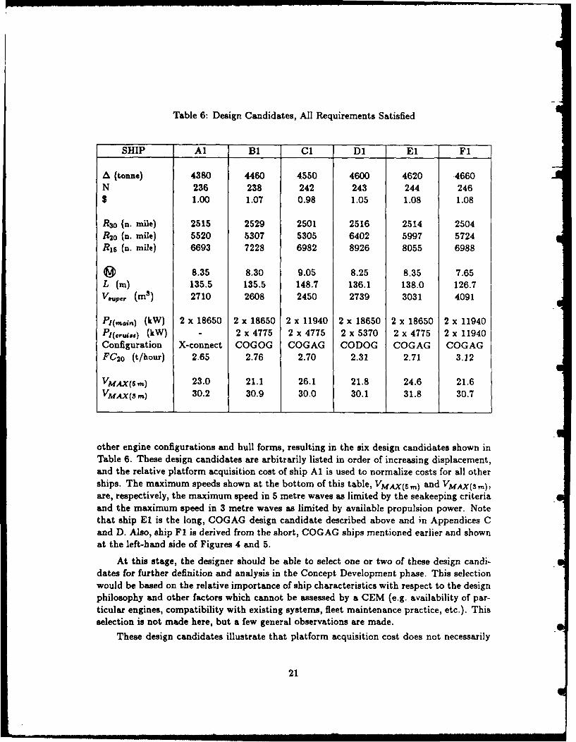
Table 6: Design Candidates, All Requirements Satisfied
SHIP Al B1 C1 Dl El F1
A (tonne) 4380 4460 4550 4600 4620 4660N 236 238 242 243 244 246$ 1.00 1.07 0.98 1.05 1.08 1.08
R 3 0 (n. mile) 2515 2529 2501 2516 2514 2504R 20 (n. mile) 5520 5307 5305 6402 5997 5724R15 (n. mile) 6693 7228 6982 8926 8055 6988
M 8.35 8.30 9.05 8.25 8.35 7.65L (m) 135.5 135.5 148.7 136.1 138.0 126.7V.upe, (M3 ) 2710 2608 2450 2739 3031 4091
Pl(,,,,) (kW) 2 x 18650 2 x 18650 2 x 11940 2 x 18650 2 x 18650 2 x 11940P1(.&ie) (kW) - 2 x 4775 2 x 4775 2 x 5370 2 x 4775 2 x 11940Configuration X-connect COGOG COGAG CODOG COGAG COGAGFC 20 (t/hour) 2.65 2.76 2.70 2.31 2.71 3.12
VMAXj(,6) 23.0 21.1 26.1 21.8 24.6 21.6VMAX(3m) 30.2 30.9 30.0 30.1 31.8 30.7
other engine configurations and hull forms, resulting in the six design candidates shown inTable 6. These design candidates are arbitrarily listed in order of increasing displacement,and the relative platform acquisition cost of ship Al is used to normalize costs for all otherships. The maximum speeds shown at the bottom of this table, VMAX(5 m) and VMAX(s,.),are, respectively, the maximum speed in 5 metre waves as limited by the seakeeping criteriaand the maximum speed in 3 metre waves as limited by available propulsion power. Notethat ship El is the long, COGAG design candidate described above and in Appendices Cand D. Also, ship F1 is derived from the short, COGAG ships mentioned eariier and shownat the left-hand side of Figures 4 and 5.
At this stage, the designer should be able to select one or two of these design candi-dates for further definition and analysis in the Concept Development phase. This selectionwould be based on the relative importance of ship characteristics with respect to the designphilosophy and other factors which cannot be assessed by a CEM (e.g. availability of par-ticular engines, compatibility with existing systems, fleet maintenance practice, etc.). Thisselection is not made here, but a few general observations are made.
These design candidates illustrate that platform acquisition cost does not necessarily
21

Table 7: Design Candidates, 2000 n. mile Range at 30 knots.
SHIP A? B2 I C2 1 D2 E2 -F2 A3
A (tonne) 4200 4280 4120 4420 4350 4440 4100N 229 232 226 237 235 238 225$ 1.00 1.07 0.96 1.05 1.07 1.08 0.99
R 30 (n. mile) 2005 2018 2083 2042 2007 2046 2005R 20 (n. mile) 4748 4597 4521 5805 4954 5254 4542R1 6 (n. mile) 5493 5944 5937 7260 6587 6190 5367
8.20 8.30 8.85 8.30 8.20 7.50 8.40L (m) 131.2 133.7 140.7 135.1 132.8 122.3 133.3Veupet (MS) 4153 3625 1805 3773 3381 4752 2996
P (mai) (kW) 2 x 18650 2 x 18650 2 x 11940 2 x 18650 2 x 18650 2 x 11940 2 x 18650Pr(ctUi.e) (kW) - 2 x 4775 2 x 4775 2 x 5370 2 x 4775 2 x 11940 -Configuration X-connect COGOG COGAG CODOG COGAG COGAG X-connectFC 20 (t/hour) 2.47 2.57 2.63 2.07 2.69 3.00 2.57
VMAX(5 M) 22.8 23.5 23.6 24.0 23.5 21.6 23.5VMAX(S M) 30.1 30.1 30.0 30.0 31.5 30.0 30.2
increase with increasing displacement and length. The variation of cruise and main engineshas a significant effect on platform acquisition cost. For example, consider ships Al and C1;ship C1 is 170 tonnes heavier and 13.2 metres longer, but has lower platform acquisitioncost due to its lower installed propulsion power.
By comparing the performance of the design candidates with the original requirements,it is apparent that the 2500 nautical mile range requirement at 30 knots is dominant. Thisbecame obvious early in the design process, as the displacement of ships otherwise acceptablehad to be increased significantly to obtain sufficient fuel. Thus, the designer may feel thatthese design requirements are unbalanced, and it may be worth investigating the effects ofreducing the required range at design speed. This option was investigated by reducing thedesign-speed range requirement to 2000 nautical miles, and the results are shown in Table 7.These ships are essentially scaled-down versions of those shown in Table 6, and are listedin the corresponding order.
In most cases, there is no significant reduction in platform acquisition cost between thetwo groups of design candidates, but the generally lower fuel consumption at cruise speed(20 knots) and reduced complement will provide significant reductions in future operationalcosts.
The last ship shown in Table 7, labelled A3, is a variant of ship A2 which is includedto illustrate how decisions made by the designer in controlling the design process affect the
22

design solution. Ship A2 was derived from Al by simply reducing displacement and lengthto match the reduced range at design speed. Since volume requirements remain constant(except for a small difference due to reducing complement), the superstructure volume ofA2 is significantly larger than for Al (4153 m3 vs 2710 ms). A different approach was usedto generate ship A3, in which displacement was reduced but length was held approximatelyconstant. In this case, ships Al and A3 have approximately the same superstructure volumeand the relatively low resistance of A3 with respect to the shorter A2 results in a lowerdisplacement for A3.
The final comments on these design candidates concerns another aspect of the impact ofdesigner's decisions on the design solution. Ships C1 and C2 were generated by increasingship length until the powering requirements could be satisfied by relatively low installedpower; however, it was not possible to generate these ships without changing the SHOP5default calculations for the number of internal bulkheads, Nbk, and waterplane coefficient,Cw. Originally, all likely candidates for this long hull form were rejected by SHOP5 forexceeding the maximum vertical centre of gravity for positive stability in the damagedcondition, KG,, (described in Reference 1). This criterion was temporarily by-passed bydefining a large user-supplied value for KG,,,,. of 10.0 metres, and so ships generated fromsubsequent input files were effectively not limited by this criterion. With this constraintremoved, a number of design candidates were generated and the FIVPOS graphics showedthat many had adequate intact stability. Thus, if the damaged stability characteristics ofthese ships could be improved without degrading other performance parameters, it shouldbe possible to generate acceptable design candidates. This was done by increasing Nbak
from the default value of 16 to 17, and by increasing Cw from the default of 0.728 to 0.768.Subsequent runs of SHOP5 with these modified values for Nbwt and Cw produced designcandidate CI, which also satisfies the KGma: criterion. An additional change was necessarybefore ship C2 could be generated, as the mininum superstructure volume used in theprocedure for sizing the superstructure produced over-large superstructures for these ships,causing inadequate intact stability due to relatively high vertical centres of gravity. TheFIVPOS graphics for these ships showed that these ships had excess combat system volume,which indicated that it may be possible to increase U7M/B by reducing superstructurevolume, and still satisfy the combat system requirements. This was done by defining areduced value for the minimum superstructure volume, and resulted in ship C2.
This entire design exercise, including investigating the reduced design-speed range re-quirement was performed by a single person in three days. Thus, the designer can rapidlyinitialize more detailed design by selecting one (or more) of the ships from Table 6, and canalso indicate that significant savings in operational costs are possible if the design-speedrange requirement is reduced.
8 Other uses for the SHOP5 System
Most of this documentation assumes that SHOP5 is being used to initialize the new-shipdesign process; however, it is a useful tool for other purposes, including:
23

" evaluating the effects of new or different technologies on ship size, performance and
relative cost 3.
" evaluating the relative impact of design requirements and design practice (i.e. margins,methodology, etc.) on the ship platform;
" initial evaluation of design proposals or major refit/modernization programs;
* comparative naval architecture [9];
" initializing and/or performing specific parametric studies (e.g. [10]); and,
* in conjunction with other CEMs, evaluating the relative merits of the monohull
frigate/destroyer for anticipated future requirements.
Of course, the level of detail used by SHOP5 means that it does not perform all cal-culations required for these purposes, but it is a useful tool in all cases. For example, theprocess of modeling a design proposal or foreign ship with SHOP5 rapidly highlights anyanomalies (i.e. standard of accomodations, machinery space vs installed power, propulsiveefficiency vs contemporary practice, etc.).
9 Concluding Remarks
The SHOP5 System provides a fast, flexible and user-friendly design tool for Concept Explo-ration design of monohull frigates and destroyers. The system has three major components;program FIVPRE for defining and modifying input, program SHOP5 for analysing the shipsdescribed by the input, and program FIVPOS for examining the characteristics of feasibledesign candidates using computer graphics.
The design logic used in SHOP5 is relatively simple; given ship size, hull form, majorsystems and design requirements, SHOP5 calculates performance and capability, including:deck wetness, vertical accelerations, and slam force in head seas; resistance, powering andrange in calm water and waves; propulsion and electrical generation systems modelingand performance; distribution of weight and volume components; preliminary intact anddamaged stability analysis; and a platform acquisition cost. This cost does not includeany combat system or future operating costs, and is not sufficiently detailed for budgetarypurposes; however, it is a valuable comparative parameter for performing design trade-offs.
The SHOP5 input consists of the ship description, design requirements and designcriteria. Most of these parameters have pre-programmed default values representative ofcontemporary NATO practice, which can be redefined by user-supplied input for cases whenthe defaults are not appropriate. SHOP5 can be used in either a SEARCH or DESCRIBEmode. In the SEARCH mode, the designer specifies a range of ship sizes and underwaterhull form coefficients, which defines a multi-dimensional search space. Each combinationof ship size and hull form coefficients produces a possible design candidate, and up to 800
8SHOP5 does not explicitly consider operating costs, but it does provide key information, especially fuelconsumption.
24

can be considered on a single execution of the program. When an individual ship does notsatisfy all design criteria, then it is rejected and the next possible ship is considered. Thecharacteristics of feasible ships are transferred to program FIVPOS, where the designeruses computer graphics to examine and select possible design candidates. The closed-loopstructure of the SHOP5 System allows the user to transfer ship data from FIVPOS toFIVPRE, where they are arranged to form a new input file for SHOP5. This file can beused immediately to examine the selected ships in the DESCRIBE mode, or it can bemodified to form a new SEARCH mode input file. In the DESCRIBE mode, more detailedcalculations are performed for up to eleven individual ships and no ships are rejected. Thismode is used to model existing ships for direct comparison with design candidates generatedby SHOP5 and to examine ships rejected in the SEARCH mode.
The primary application for SHOP5 is to initialize the new-ship design process by de-termining the size, hull form and major systems of the ship or ships best suited for thedesign requirements. The iterative process used for design optimization was illustratedby generating a number of design candidates for a typical frigate mission. Also, this ex-ample emphasized the designer's responsibility for configuring suitable input and selectingappropriate design candidates. All SHOP5 input parameters and algorithms for design cal-culations were described in detail, with special attention to the options for replacing inputparameter default values and internal calculations with user-supplied input.
Other uses for the SHOP5 System include assessing the effects of new or differenttechnologies, design requirements and design practice on performance and capability, ini-tial evaluation of design proposals and major refit or modernization programs, comparativenaval architecutre, performing special parametric studies, and examining future require-ments.
L5

IeAsIs SHIP I
SEAKEEPING L ' DIMENSIONS
STRUCTURE AHULL FORM
FLOODING CONTRACT Z PROPULSIONDESIGN I
STABILITY COMBATSYSTEMS
VOLUMES SHIP SYSTEMSWEIGHTS
Figure 1: Traditional Design Spiral
27

SHOP5 System
SSTARTr
FIVPRE
DEFINE OR MODIFY SHIP DESCRIPTION,DESIGN REQUIREMENTS, DESIGN CRITERIA,
AND CONTROLS FOR DESIGN METHODOLOGY
SHOP5
CALCULATE PLATFORM PERFORMANCE,CAPABILITY, AND ACQUISITION COST
FIVPOS
INSPECT AND COMPARE FEASIBLEDESIGN CANDIDATES.
SELECT DESIGN CANDIDATES
END
Figure 2: SHOP5 System Programs
28
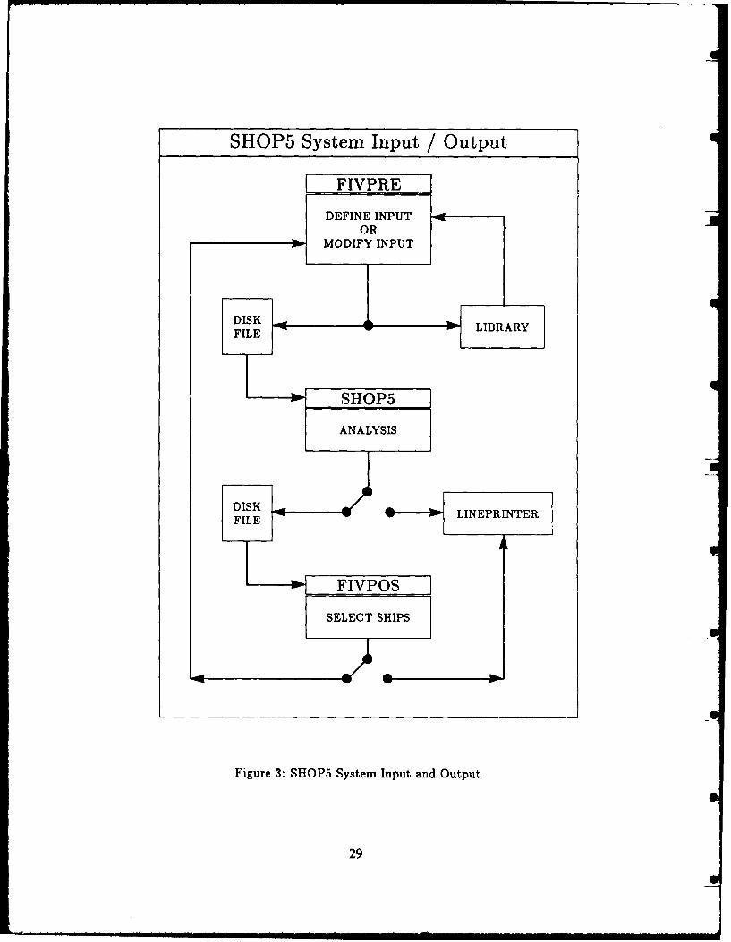
SHOP5 System Input / Output
(FIVPRE
OR
FILEO
Figre3:SHP5SsemIputadOtu
29LYI

z0
w 2 2 0 0 -
0.i
02000'-4inw ro 1800
z 1600cc 0 2 4 6 8 10
SHIP NUMBERS
Figure 4: Range at Design Speed, 'First-Run' Ships
I-
c 260 I 1 ' ' I
z0
- 250U)
<240-C---0 24
7 ___ __ _____
U-1~ 230-J 0 2 4 6 6 10
SHIP NUMBERS
Figure 5: Platform Acquisition Cost, First-Run Ships
30
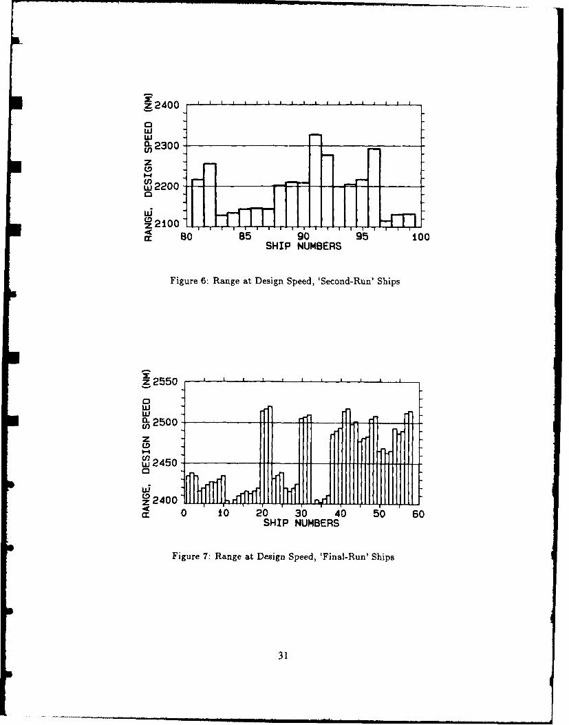
z 24 00 . . . . . . . . . . . . . I
wCL2300O
zCD0-f
210
4
SHIP NUMBERS
Figure 6: Range at Design Speed, 'Second-Run' Ships
z055
wCL2500 - - -
z
C
14
d: 0 to 20 30 40 50 60SHIP NUMBERS
Figure 7: Range at Design Speed, 'Final-Run' Ships
31

Appendix A: SHOP5 Input Records
Overview of SHOP5 Input Records
The SHOP5 input parameters are arranged in the following records.
Record 1 Title
Record 2 Program Control Integers (PCI)
Record 3 Primary Input (PRIM)
Record 4 Method Control Integers (MCI)
Record 5 Optional Input Parameters (OPT)
Record 6 Design/Seakeeping Criteria (CRIT)
Record 7 Appendage Resistance Coefficient (IAPPND)
Record 8 Overall Propulsive Coefficients (IPROP)
Record 9 Superstructure Material (ISTRUC)
Record 10 Propulsion System (IENGIN)
Record 11 Electrical Generation System (IGEN)
Record 12 Superstructure Size Variations (IVOLUM)
Record 13 Cost Factors (ICOST)
Uppercase letters in (...) brackets define names recognized by FIVPRE for invokingparameter-access menus. For example, the FIVPRE command CHANGE MCI invokes themenu for changing method control integers. Records 1, 2 and 3 are required input. Records4, 5 and 6 are optional and one or more of Records 7 through 13 may be required to defineadditional input for Record 4.
The following descriptions of the SHOP5 input records use the SHOP5 lineprinternotation for all parameter names, which is also used on-screen by FIVPRE and FIVPOS,and on all SHOP5 System lineprinter output. The Notation section at the front of thisTechnical Memorandum has separate entries for parameters whose lineprinter notation issignificantly different from that used in the text.
When using program FIVPRE, some of the SHOP5 input parameters are defined au-tomatically, and so the user does not have explicit knowledge of all required input. Thedifferences between the on-screen input structure used by FIVPRE and the on-disk inputstructure required by SHOP5 are only important when the user is defining or modifyingan input file without using FIVPRE. In this case, Appendices A and B provide completedocumentation of the SHOP5 input record structure.
An example input file is presented in Table A.9 at the end of this appendix.
33

Record 1: Title
TITLE Maximum of 80 characters, first line of file
Record 2: Program Control Integers
MODE Defines type of mode: SEARCH or DESCRIBE0 SEARCH moden DESCRIBE mode, n = number of ships, 1 < n < 11
UNITS Defines type of units for input and output 0 < UNITS < 30 Input FPS, Output FPS1 Input METRIC, Output FPS2 Input FPS, Output METRIC3 Input METRIC, Output METRIC
IPOST Will post-processor (FIVPOS) be used?0 NO post-processor not used1 YES post-processor will be usedNotes: (a) in SEARCH mode, if IPOST = 0, define ILPT = 1
if IPOST = 1, define ILPT = 0(b) in DESCRIBE mode, define IPOST = 0
ILPT Will SEARCH mode ship data be written to lineprinter ?0 NO ship data not written to lineprinter1 YES ship data written to lineprinter, one page per shipNotes: (a) summary cf input always written to lineprinter
(b) see Note (a) lor IPOST, above.(c) in DESCRIBE mode, define ILPT = 1
LEGEND Will a legend of abbreviations accompany the lineprinter output ?0 NO legend not written1 YES legend written to lineprinter
NCON number of method control integers redefined (see Record 4)
NOPT number of optional input parameters redefined (see Record 5)
NLIM number of design criteria redefined (see Record 6)
Order of input: eight integers on one line.
34

Record 3: Prim3ry Lvput
The primary input define the characteristic dimension, underwater hull form and designrequirements. These input are separated into two sub-records; Record 3A for the SEARCHmode and Record 3B for the DESCRIBE mode.
Record 3A: SEARCH Mode Primary Input
Only used when program control integer MODE = 0 (Record 2).
Characteristic dimension: (see IDIMEN, Record 4)XXXIo low valueXXXhi high valueII number of values, I < 11 < 11
Length/Displacement ratio, (0:CrMlo low valueCrMhi high value12 number of values, 1 < 12 < 11
Prismatic coefficient:CPio low value
CPhi high value13 number of values, 1 < 13 < 11
Block Coefficient:CBio low valueCBhi high value
4 number of values, 1 < 14 < 11
Beam/Draft ratio:B/Tio low valueB/Thi high value15 number of values, 1 < 15 < 11
Note: maximum total number of ships is 800 (i.e. lIj Ii < 800)
R(Ve) Minimum acceptable range (n. miles) at endurance speed, Ve
Wc Combat systems weight (t:ton)
Vd Design speed (knots)
Vc Cruise speed (knots)
Ve Endurance speed (knots)
VW Seakeeping speed (knots)
Hw Seakeeping significant wave height (m:ft)
35

Order of input: XXX1o IXhi ILCrMlo CrMhi 12Cplo Cphi 13Cblo Cbhi 14B/Tlo B/Thi 15TR(Ve) Wc Vd Vc Ve Vw Hw
Record 3B: DESCRIBE Mode Primary Input
Only used when program control integer MODE > 0 (Record 2).
XXX Characteristic dimension (see IDIMEN, Record 4)
CrM Length/Displacement ratio, gCp Prismatic coefficient
Cb Block coefficient
B/T Beam/Draft ratio
Wc Combat systems weight (t:ton)
Vd Design speed (knots)
Vc Cruise speed (knots)
Ve Endurance speed (knots)
VW Seakeeping speed (knots)
Hw Seakeeping significant wave height (m:ft)
Notes: (a) number of ships = MODE (Record 2)(b) every ship requires explicit input for each parameter
Order of input: XXX CrM Cp Cb B/T Wc Vd Vc Ve Vw Hw
for example: 4000 8.5 0.60 0.49 2.95 350 32 20 15 20 5(MODE = 3) 4200 8.5 0.60 0.49 2.95 350 32 20 15 20 5
4400 8.5 0.60 0.49 2.95 350 32 20 15 20 5
36

Record 4: Method Control Integers
Only used when program control integer NCON > 0 (Record 2).
I Integer descriptor number of MCI being redefined
J(I) Integer value of MCI(I)
Notes: (a) Acceptable I and J(I) values are shown in Table A.1, below.
Table A. 1: Method Control Integers
I I Name JCW) Option AdditionalI i I I Input
1 IDIMEN 0 displacement (t:ton) noCharacteristic Dimension 1 length (m:ft) no
2 beam (m:ft) no3 draft (m:ft no
2 IRESID 0 NRC FSS noResiduary Resistance 1 other SHOP5 database no
3 IAPPND 0 SHOPS noAppendage Resistance 1 user-defined Record 7
4 IPROP 0 SHOPS CPP noPropulsive Efficicency 1 SHOPS fixed pitch no
2 user-defined OPCs Record 85 ISTRUC 0 homogeneous no
Structural Material 1 hybrid Record 96 IENGIN 0 SHOPS rubber engines no
Propulsion System 1 user-defined rubber engines Record 10A2 SHOPS real engines Record 10B3 user-defined real engines Record 10C
7 ICONFG 0 fixed configuration noEngine Configuration 1 variable configuration Record 10D
8 IGEN 0 SHOPS diesel noElectrical Generation 1 SHOPS gas turbine no
2 user-defined Record 113 SHOPS integrated no
9 IVOLUN 0 Vouper fixed noSuperstructure Volume 1 Vsuper = f(Vcombat) Record 12
2 Vauper = f(GM/B) Record 1210 ICOST 0 SHOPS no
Cost Factors 1 user-defined Record 13
(b) IDIMEN and ICONFG are not explicitly defined as method control integersin FIVPRE.
Order of input: I Jfor example: 1 1 (i.e. characteristic dimension: length)
(NCON = 3) 6 2 (i.e. propulsion system: SHOP5 real engines)7 1 (i.e. electrical generators: SHOP5 gas turbines)
37

Record 5: Optional Input Parameters
Only used when program control integer NOPT > 0 (Record 2).
I Integer descriptor number of parameter being redefined
XCI) Real or integer value of parameter(I)
Note: see Appendix B (page 48) for values of I and XCI).
Order of input: I XCI)for example: 1 10 (i.e. D = 10 mn)
(NfJPT = 4) 5 220 (i.e. N = 220)8 -15 (i.e. Ldamage/L = 15)
41 -16 (i.e. Vn/N = 16 ms/person)
Record 6: Design Criteria
Only used when program control integer NLIM > 0 (Record 2).
I Integer descriptor number of criterion being redefined
XCI) Real or integer value of criterion(I)
Noes (a) Acceptable input for I and X(I) are shown in the Table A.2, below.________Table A.2: Redefinable Design Criteria
I I Name] -D -efault [User-Supplied Input, X(I)1 WetMax 60 wetness/hour WetMax = XCI)2 AccMax 0.20 gravities AccMax = X(I)3 SimMax 0.20 SimMax = X(I)4 Ef fMin 50.0 percent EffMin =XCI7 OPCmin 0.60 OPCMin = X(I)
10 KGmax calculated XCI) > 0 KGmax =X(I)__________ X (CI) < 0 KGmax/D = IX (I) I
11Vcombat Vcombat/Vt = 0.125 XCI) > 0 Vcombat = XUI)F 1___ I I_______ XCI) < 0 *Vc ombat /Vt =IX (I)l
(b) The missing I values in Table A.2 are for design criteria that cannotbe redefined by user-supplied input (e.g. minimum freeboard for reservebuoyancy).
Order of input: I Xfor example: 1 30 (i.e. WetMax = 30)
(NLIM = 2) 11 2900 (i.e. Vcombat = 2900 mn3)
38

Record 7: Appendage Resistance Coefficient
Only used when method control integer IAPPND = 1 (Record 4).
Capp Appendage resistance coefficient, dimensionless
Note: input must be defined; input of zero gives Rapp - 0
Record 8: Overall Propulsive Coefficients
Only used when method control integer IPROP = 2 (Record 4).
OPC (Vd) Overall propulsive coefficient at design speed
OPC (Vc) Overall propulsive coefficient at cruise speed
OPC(Ve) Overall propulsive coefficient at endurance speed
Note. input must be defined for all parameters; no defaults available.
Order of input: OPC(Vd) OPC(Vc) OPC(Ve)for example: 0.615 0.654 0.682
Record 9: Superstructure Material
Only used when method control integer ISTRUC = 1 (Record 4).
SSdens Density of superstructure material (t/m3 :ton/ft3 )Default (SSdens = 0): aluminum, SSdens = 2.81 t/m3 (0.075 ton/ft3 )
SSthck Average thickness of superstructure material (m:ft)Default (SSthck = 0): aluminum, SSthck = 0.016 m (0.053 ft)
Note: input must be defined for both parameters; enter zero for default(s).
Order of input: SSdens SSthckfor example: 0.0 0.020 (i.e. SSdens = 2.81 t/m S, SSthck = 0.020 m)
39
39

Record 10: Propulsion System
Only used when method control integer IENGIN > 0 and/or ICHOOS = 1 (Record 4).
The propulsion system sub-record structure is defined in Table A.3, below.
Table A.3: Propulsion System Sub-RecordsIENGIN = I Record 10A user-defined rubber engines
IENGIN = 2 Record 10B SHOP5 real engine databaseIENGIN = 3 Record 10C user-defined real engine databaseICONFG = 1 Record 1OD variable engine configuration
Record InA: User-Defined Rubber Engines
Only used when method control integer IENGIN = 1 (Record 4).
SpW2 Propulsion system specific weight, W2/Pins (kg/kW:lb/HP)Default (SpW2 = 0): SHOP5 rubber engines, approximates COGOG
KG2 Propulsion system vertical centre of gravity (m:ft) -[KG2/D]Default (KG2 = 0): KG2/D = 0.4
Nsf c Number of (SFCr, P/Pins) data-pairs input below, 0 < NsIc < 11Default (Nsfc = 0): SHOP5 rubber engines, approximates COGOG
and SFCr(I) and P/Pins(I) not input.
SFCr(I) Specific fuel consumption (kg/kW-hr:lb/HP-hr) at power ratio P/PinsI)Note: SFCr(1) must be full power SFC, SFCo
P/Pins(I) Power ratio (operating power/installed power) for SFCr(I)Notes: (a) P/Pins(1) must = 1.00 (i.e. full power)
(b) P/Pins values must be in descending order(i.e. P/Pins(I.l) < P/Pins(I))
Order of input: SpW2 KG2 Nsf cSFCr(1) P/Pins(1)SFCr(2) P/Pins(2)
SFCr (Nsfc) P/Pins(Nsfc)
for example: 5.36 -0.3 40.20 1.000.23 0.800.28 0.60
0.38 0.40
40

Record lOB: SHOPS Real Engines
Only used when method control integer IENGIN = 2 (Record 4).
ITTPE Type of engine configuration per shaft, 1 <5 ITYPE _< 61 Single gas turbine2 COGAG3 COGOG4 CODAG5 CODOG6 CODAD
IDBASE Engine data base selection, 0 < IDBASE < 10 1980 engine data base, see Table A.41 1995 engine data base, see Table A.5
Table A.4: 1980 Engine Data BaseName Type P SFC W2.
(kW) (HP) k (H--'hr)(tonne) (ton)
LM 2500 g.t. 18,650 25,000 0.23 0.38 15.65 15.40Spey g.t. 11,936 16,000 0.24 0.39 9.30 9.15DDA 570 g.t. 4,774 6,400 0.28 0.46 2.27 2.23Pielatick diesel 5,371 7,200 0.23 0.38 42.98 42.30MTU diesel 3,730 5,000 0.23 0.38 33.83 33.30
Table A.5: 1995 Engine Data BaseName Type P SFC W2
___ k) (HP) kkW rl HP h.,) [(tonne) (ton)LM 5000 g.t. 44,760 60,000 0.21 0.34 35.15 34.60FT 9 g.t. 33,570 45,000 0.21 0.35 21.09 20.76LM 2500 g.t. 22,380 30,000 0.22 0.37 15.65 15.40Spey g.t. 17,904 24,000 0.23 0.38 9.30 9.15DDA 570 g.t. 5,968 8,000 0.28 0.46 2.27 2.23Pielstick diesel 7,460 10,000 0.23 0.38 42.98 42.30MTU diesel 4,476 6,000 0.23 0.38 33.83 33.30
Order of input: ITYPE IDBASE
for example: 2 0 (i.e. COGAG configuration, 1980 data base)
41
41
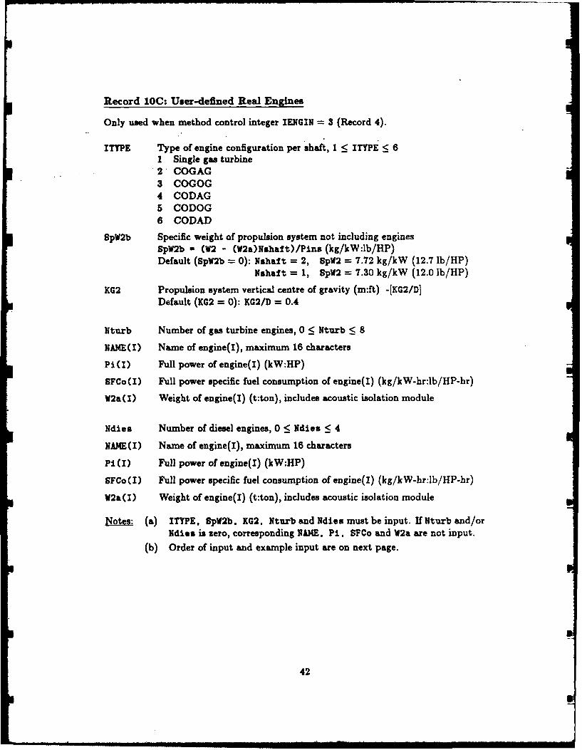
Record LOC: User-defined Real Engines
Only used when method control integer IENGIN - 3 (Record 4).
ITTPE Type of engine configuration per shaft, 1 < ITYPE < 61 Single gas turbine2 COGAG3 COGOG4 CODAG5 CODOG6 CODAD
SpW2b Specific weight of propulsion system not including enginesSpW2b a (W2 - (W2a)Nshaft)/Pins (kg/kW:lb/HP)Default (SpW2b = 0): Nshaf t = 2, SpW2 = 7.72 kg/kW (12.7 lb/HP)
Nshaft = 1, SpW2 = 7.30 kg/kW (12.0 lb/HP)
KG2 Propulsion system vertical centre of gravity (m:ft) -[KG2/D]Default (KG2 = 0): KG2/D = 0.4
Nturb Number of gas turbine engines, 0 < Nturb < 8
NAME(I) Name of engine(I), maximum 16 characters
Pi(I) Full power of engine(I) (kW:HP)
SFCo(I) Full power specific fuel consumption of engine(I) (kg/kW-hr:lb/HP-hr)
W2a(I) Weight of engine(I) (t:ton), includes acoustic isolation module
Ndies Number of diesel engines, 0 < Ndies < 4
NAME(I) Name of engine(I), maximum 16 characters
Pi(I) Full power of engine(I) (kW:HP)
SFCo I) Full power specific fuel consumption of engine(I) (kg/kW-hr:lb/HP-hr)
W2a(I) Weight of engine(I) (t:ton), includes acoustic isolation module
Notes: (a) ITYPE, SpW2b. KG2, Nturb and Ndies must be input. If Nturb and/orNdies is zero, corresponding NAME. Pi, SFCo and W2a are not input.
(b) Order of input and example input are on next page.
42

Order of input: ITYPE SpV2b KG2NturbNAME (1)Pi~i) SFCo(1) WWI()NAME (2)Pi(2) SFCo(2) W2a(2)
NAME (Nturb)
Pi (Nturb) SFCo (Nturb) W2a (Nturb)NdiesNAME (1Pi(1) SFCo(1) W2a(1)NAME (2Pi(2) SFCo(2) W2a(2)
NAME (Nturb)Pi(Ndies) SFCo(Ndies) W2a(Ndies)
for example: 6 7.2 -0.35
3BIG TURBINE20000. 0.20 25.0MEDIUM TURBINE15000. 0.22 12.0SMALL TURBINE
7500. 0.24 3.02
BIG DIESEL10000. 0.21 45.5SMALL DIESEL
4000. 0.21 30.0
43

Record 1OD: Variable Engine Configuration
Only used when method control integer ICH0OS = 1 (Record 4).This option should be used with caution, see Reference 1 for further comments.
IHIAR Integer descriptor of engine configuration hierarchy, 0 < IHIAR < 30 SHOPS noise hierarchy, see Table A.61 SHOP5 gearing hierarchy, see Table A.62 SHOPS powering hierarchy, see Table A.63 User-defined hierarchy, see NEIAR(I), below.
Table A.6: SHOP5 HierarchiesNoise Gearing PowerCODAD CODAG COGAGCODAG COGAG CODAGCOGAG COGOG COGOGCODOG CODOG CODOGCOGOG CODAD CODADSingle Single Single
NHIR(I) Integer descriptors of user-defined engine configuration hierarchy,
Notes: (a) NHIAR values only input when IHIAR = 3(b) When used, six values for NKIAR must be input(c) NHIAR integer descriptors shown in Table A.7
Table A.7: Hierarchy DescriptorsNHIAR Configuration
per shaftI Single gas turbine2 COGAG3 COGOG4 CODAG5 CODOG6 CODAD
Order of input: IHIARNIAR(1) NHIAR(2) NHIAR(3) NHIAR(4) NHIAR(5) NHIAR(6)
for example: 3654321
44

Record 11: Electrical Generation System
Only used when method control integer IGEN = 2 (Record 4).
SpW3 Specific weight of electrical systmns (kg/kW:lb/kW)SpW3 = W3/PgenDefault (SpW3 = 0): SHOPS diesel generators
KG3 Electrical systems vertical centre of gravity (m:ft) -[KG3/DDefault (KG3 = 0): SHOPS calculation
SFCg Specific fuel consumption of generators (kg/kW-hr:lb/kW-hr)Default (SFCg = 0): SHOPS diesel generators
Order of input: SpW3 KG3 SFCg
for example: 50.0 -0.75 0.0
Record 12: Superstructure Size Variations
Only used when method control integer IVOLUM > 0 (Record 4).
VaMin Minimum superstructure volume (m':ft3) -[VaMin/Vt]Default (VsMin = 0): SHOP5 calculation, assumes hangar
VsaMx Maximum superstructure volume (m$:ft3 ) -[VsMax/VtlDefault (VsMax = 0): SHOPS calculation
GM/B Target value for metacentric height/beam ratio, see note (a).Default (GM/B = 0): GM/B = 0.10
Notes: (a) GM/B only input when IVOLUM = 2.(b) When IVOLUM = 1, target value for combat systems volume is defined by
Vcoabat, design criterion (Record 6).
Order of input: VsMin VsMax GM/B (assume IVOLUM = 2)
for example: 1750. -0.32 0.08
45
- -- -- = .. = = i ,,..,, i~ mn i lmiimm i i m ll ~ mlmm mmm t° '

Record 13: Cost Factors
Only used when method control integer ICOST 1 (Record 4).
NCOST Number of cost factors being redefined
I Integer descriptor of cost factor being defined, 1 < I < 16
AK(I) New value of cost factor(l)
Note." Table A.8 shows the cost categories for each value of I and also showsthe SHOP5 default AK(I) values. See Reference 1 for information on thecost estimating equations and units of cost factors.
Table A.8: Cost FactorsI Cost Category Default
AKCI)1 Hull structure 18.002 Superstructure, MCI ISTRUC = 0 18.00
ISTRUC = 1 40.003 Not used by SHOP54 Diesel engines 1.255 Gas turbine engines 3.256 Electrical systems 150.007 Auxiliary systems 90.008 Outfit and furnishings 65.009 Shipyard construction 1.00
10 Design and engineering, lead ship 0.5011 Design and engineering, follow-on ship 0.0512 Construction services 0.4013 Shipyard profit, lead ship 1.1514 Shipyard profit, follow-on ship 1.1515 Miscellaneous surcharges, lead ship 1.3316 Miscellaneous surcharges, follow-on ship 1.28
Order of input: NCOST1(1) A(1)1(2) U(2)
I(NCOST) AK(NCOST)
for example: 31 15.57 75.013 1.01
46

Example Input File
Table A.9 contains an example input file which defines input for most of the SHOP5 inputrecords. This example input file is the same as the first file produced in the design opti-mization example in Appendix C. The ...... Record (I)" notation in Table A.9 is onlyincluded for identifying individual input records; it is not normally present.
Table A.9: Example Input File
DESIGN OPTIMIZATION. COGAG CONFIG ..................... Record (1)
0 3 1 0 0 2 6 2 .................. Record (2)3500.000 4500.OW0 6 ............................... Record (3A)
7.000 g.000 50.590 0.590 10.490 0.420 12.800 3.200 5 H
4500.00 375.00 30.00 20.00 20.D0 20.00 5.006 2 ................................................. Record (4)9 11 " H
1 10.0000 ...................................... Record (5)5 -0.8800 H H
8 -0.1500 H "19 4000.0000 H H
33 50.0000 H H
41 -16.0000 " H
1 30.0000 ...................................... Record (6)11 2900.0000 " H
2 0 .................................................. Record (10)2 -0.3000 ............................................. Record (12)
47
i L

Appendix B: Optional Input Parameters
SHOP5 uses a total of 44 optional input parameters to define details of geometry, systems,environment and design margins. Each optional -input parameter has a default value or
method which is used when the parameter is not explicitly re-defined by the user. Thealgorithms used to calculate the defaults are described in Reference 1.
This appendix describes the optional input parameters, including; names, descriptions,
units and defaults. Most names are a either a standard symbol (e.g. CV for waterplane coef-ficient) or descriptive abbreviation (e.g. Nshaft for number of propeller shafts). The namesare shown in the lineprinter format, which is also used on-screen by FIVPRE and FIVPOS,and on the SHOP5 and FIVPOS lineprinter output. When using program FIVPRE toprepare the SHOPS input file, individual optional input parameters can be accessed usingthe CHANGE command (abbreviation C). The parameter is identified by entering eitherits name or part of its description (e.g. C CW or C WAT COEF).
This appendix uses the following format to describe each parameter.
I name description (units) -[negative definition]
default value or method, and special notes
where I is the integer descriptor number defined in Record 5, Appendix A.
As indicated above, many of the optional input parameters accept either positive ornegative input. In most cases, negative input defines a non-dimensional form of the param-eter. For example (in metric units), input of 10 for midship hull depth, D, defines D = 10metres; whereas, input of -12 defines the ratio L/D = 12. When negative input changes thedefinition of a parameter, then two names are shown. For example, consider the margin onpersonnel volume, dVn, which has the following description.
41 dVn Margin on personnel volume, Vn (mS:ft s ) -[Vn/N]Vn/N Standard of Accomodation (mS/person:ftS/person)
Vn/N is not a margin
This parameter has two definitions: for positive input, it is a margin, dVn (m3s:ft),
which is added to the SHOPS estimate for personnel volume, Vn; for negative input, it is the
standard of accomodation (personnel volume/person ratio), Vn/N (mS/person:ft3 /person).
For example (in metric units), input of 200 for dVn defines dVn = 200 m3 , and the SHOP5estimate for Vn is increased by 200 mS. Conversely, input of -16 for dVn defines Vn = 16 N(m 3/person), and the SHOP5 algorithm for estimating Vu is not used.
48
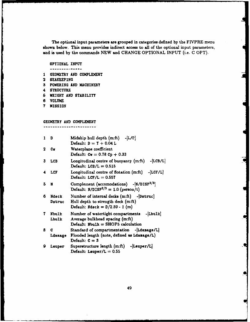
The optional input parameters are grouped in categories defined by the FIVPRE menushown below. This menu provides indirect access to all of the optional input parameters,and is used by the commands NEW and CHANGE OPTIONAL INPUT (i.e. C OPT).
OPTIONAL INPUT
1 GEOMETRY AND COMPLEMENT2 SEAKEEPING3 POWERING AND MACHINERY4 STRUCTURE6 WEIGHT AND STABILITY6 VOLUME7 MISSION
GEOMETRY AND COMPLEMENT
1 D Midship hull depth (m:ft) -[LID]Default: D = T + 0.04 L
2 Cv Waterplane coefficientDefault: Cw = 0.78 Cp + 0.33
3 LCB Longitudinal centre of buoyancy (m:ft) -[LCB/L]Default: LCB/L = 0.515
4 LCF Longitudinal centre of flotation (m:ft) -[LCF/L]Default: LCF/L = 0.557
5 N Complement (accomodations) -[N/DISPl/ 3 ]
Default: N/DISP2/ 3 = 1.0 (person/t)
6 Ndeck Number of internal decks (m:ft) -[Dstruc]Dstruc Hull depth to strength deck (m:ft)
Default: Ndeck = D/2.59 - I (m)
7 Nbulk Number of watertight compartments -(Lbulk]Lbulk Average bulkhead spacing (m:ft)
Default: Nbulk = SHOP5 calculation
8 C Standard of compartmentation -[Ldamage/L]Ldamage Flooded length (note, defined as Ldamage/L)
Default: C = 39 Lsuper Superstructure length (m:ft) -[Lsuper/LJ
Default: Lsuper/L = 0.55
49

SEAKEEPING
10 Ffp Freeboard at FP (m:ft) -IFfp/LIDefault: Ffp/L = 0.093 - 0.00021 L
11 To Wave modal period, seakeeping (sec)Default: To = f(Hw), winter North Atlantic
12 Iccli RMS vertical acceleration for zero percent crew effectivenessDefault: AccHi = 0.25 (gravities)
13 AccLo RMS vertical acceleration for 100 percent crew effectivenessDefault: AccLo = 0.05 (gravities)
POWERING AND MACHINERY
14 Ca Model-ship correlation allowanceDefault: Ca = 0.0005
15 dPe Design margin on effective power, PePe = (1 + dPe) Rt VDefault: dPe = 0.10 (i.e. 10 percent)
16 DIAM Propeller diameter (m:ft) -[DIAM/T]
Default: DIAM/T = 1.0 for Nshaft = 2DIAM/T = 1.1 for Nshaft = 1
17 Nshaft Number of propeller shaftsDefault: Nshaft = 2
18 Ngen Number of ship service electrical generatorsDefault: Ngen = 4
19 Pgen Electrical power installed (kW) -[Pgen/DISP]Default: Pgen/DISP = 1.0 (kW/t)
20 avPgen Average cruising electrical power (kW) -[avPgen/PgenDefault: avPgen/Pgen = 0.25
21 Hw(r) Significant wave height for powering and range (m:ft) -[Hw(r)/LDefault: Hw(r) = 3.0 (m)
22 To (r) Wave modal period for powering and range (sec)Default: To(r) f(Hw(r)), winter North Atlantic
50

STRUCTURE
23 YIELD Yield strength of hull material (ton/in2 :t/cm2 )Default: steel, YIELD = 2.835 t/cm2 (18.0 ton/in2 )
24 DENS Density of hull material (ton/ft3:t/Mn)Default: steel, DENS = 7.858 t/m s (0.219 ton/fts)
25 Fmod Factor on structural modulusFmod multiplies midship sectional modulusDefault: Fmod a 1.0
WEIGHT AND STABILITY All default values for weight margins are zero.
26 dW1 Margin on structural weight, W1 (ton:t) -[dWI/W1]
27 dW2 Margin on machinery weight, W2 (ton:t) -[dW2/W2]
28 RAFT Margin on engine rafting (ton:t) -[RAFT/W2]
29 GEAR Margin on gear box weight (ton:t) -[GEAR/Pins]
30 dW3 Margin on electrical systems weight, W3 (ton:t) -[dW3/W3]
31 dW5 Margin on auxiliary systems weight, W5 (ton:t) -[dW5/WS]
32 dW6 Margin on outfit and furnishings weight, W6 (ton:t) -[dW6/W]
33 dWb Margin on Wbasic, (ton:t) -[dWb/Wb]Wbasic a WI + W2 + W3 + W5 + W6Use dWb for future growth margin
34 dWd Margin on disposable loads weight, Wd (ton:t) -[dWd/Wd]
35 KGb Vertical centre of gravity of dWb (m:ft) -[KGb/D]Default: KGb/D = 0.65
36 KGc Vertical centre of gravity of Wcombat (m:ft) -[KGc/D]Default: KGc/D = 1.00
51
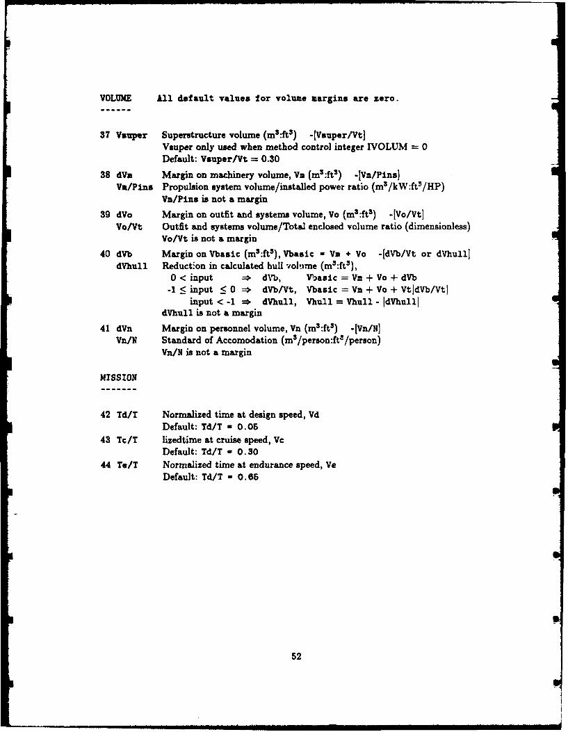
VOLUME All default values for volume margins are zero.
37 Vauper Superstructure volume (M5:ft3) -[Vsuper/Vt]Vauper only used when method control integer IVOLUM = 0Default: Vsuper/Vt = 0.30
38 dY. Margin on machinery volume, Va (ms:fts) -I Va/Pins)Vm/Pins Propulsion system volume/installed power ratio (m8/kW:fts/HP)
Va/Pins is not a margin
39 dVo Margin on outfit and systems volume, Vo (in5 :ft3) - [Vo/Vt]Va/Vt Outfit and systems volume/Total enclosed volume ratio (dimensionless)
Vo/Vt is not a margin
40 dVb Margin on Vbasic (m3:ft3), Vbasic - V. + Vo -[dmb/Vt or dVhull]dVhull Reduction in calculated hull -ioluire (m3:ft3) I
0 < input * d~rb, V)asic = Vm + Vo + dVb-1 :5 input <0 * dVb/Vt, Vbasic = Vm + Vo + VtldVb/Vtl
input < -1 * dVhull, Thull = Vhull - IdVhullIdVhull is not a margin
41 dVn Margin on personnel volume, Vii (mS:ft3) -fyi/NIVn/N Standard of Accomodation (m3/person:ft- /person)
Vn/N is not a margin
MISSION
42 Td/T Normalized time at design speed, VdDefault: Td/T a 0.-05
43 Tc/T lizedtime at cruise speed, VcDefault: Td/T - 0. 30
44 Te/T Normalized time at endurance speed, VeDefault: Td/T - 0. 65
52

Appendix C: Design Optimization Example, Session 1
This example terminal session demonstrates using FIVPRE to define a new SHOP5 inputfile and illustrates the iterative process of running SHOP5, examining ships with FIVPOSand re-defining the initial input to home-in on a desireable s-ign candidate. None of theships generated on the initial run have sufficient range at 30 knots, but some interestingtrends regarding platform acquisition cost, range and superstructure volume are evident.
Most program menus for controlling input are shown only once; however, editorialcomments indicate where text has been omitted. Editorial comments are delimited asfollows,
--- <editorial comments>---
All user-supplied input follows a "->" prompt. When no input is shown after thisprompt, then the user has simply pushed the Return-key (i.e. "null" input), and a defaultresponse is used. The default response (or action) is defined within <... > brackets in theprompt-line. When no default response is defined, then null input means "preserve thecurrent value".
SHOPS System: Program Control
1 Run FIVPRE2 Run SHOPS3 Run FIVPOS4 Lineprinter Control5 Edit6 Help
99 EXIT
Enter NUMBER -> 1
FIVPRE. Pre-processor for SHOPS
reading library file .....
FIVPRE: enter command a> NEW
Enter TITLE -> design optimization, COGAG config.
Program Control Integers (PCI)
MODE
O SEARCHI DESCRIBE
MODE ? <SEARCH> a>
53
-- - -,- --. m~mmmimallMldlialillImi B i i l li i

UNITS
0 Input: FPS Output: FPSI Input: metric Output: FPS2 Input: PPS Output: metric3 Input: metric Output: metric
UNITS ? <metric-metric> ->
POST-PROCESSOR
0 NO. Post-processor (FIVPOS) will NOT be used1 TES. Post-processor will be used
POST-PROCESSOR ? <Tea> ->
LEGEND
0 NO LegendI Legend of SHOPS abbreviations written on lineprinter
LEGEND ? <No> a>
Characteristic Dimension (1iX)
0 Displacement (full load)I Length2 Beam3 Draft
Enter selection <Displacement> ->
Primary Input (PRIM)
DISP; Displacement (t:ton) Minimum -> 3500Maximum => 4500
Number of values -> 6
CrM; Length/Displacement Ratio Minimum => 7Maximum -> 9
Number of values w> 5
Cp; Prismatic Cc-fi-4ent Minimum => .59Maximum -> .59
Cb; Block Coefficient Minimum -> .49Maximum -> .49
B/T; Beam/Draft Ratio Minimum a> 2.8Maximum -> 3.2
Number of values -> 5
Design Requirements
R(Ve); Range at Endurance Speed -> 4500Wcombat; Combat System Weight (t:ton) a> 375Vd; Design Speed (kt) -> 30Vc; Cruise Speed (kt) -> 20Ve; Endurance Speed (kt) n> 20Vw; Seakeeping Speed (kt) -> 20Hw; Seakeeping Wave Height (m:Wft) -> 5
54

Method Control Integers (MCI)
1 IRESID; Residuary Resistance2 IAPPND; Appendage Resistance3 IPROP; Propeller Type or OPC Values4 ISTRUC; Hull/Superstructure Material5 IENGIN; Propulsion System6 IGEN; Ship Service Electrical Generators7 IVOLUM; Superstructure Sizing Method8 ICOST; Cost Factors
Enter selection <exit> => 5
Propulsion System (IENGIN)
0 SHOPS Rubber Engines1 User-Supplied Rubber Engines2 SHOPS Real Engines3 User-Supplied Real Engines
Enter selection => 2
Engine Data Base
o 1980 Engine Data Base1 1996 Engine Data Base
Enter selection <1080> ->
Engine Configuration (ITYPE)
1 Single gas turbine2 COGAG (COmbined Gas And Gas)3 COGOG COmbined Gas Or Gas)4 CODAG COmbined Diesel And Gas)5 CODOG COmbined Diesel Or Gas)6 CODAD COmbined Diesel And Diesel)
Enter selection => 2
Engine Configuration Selection
0 SHOP5 must use this Configuration1 SHOPS may change Configuration (not recommended)
Enter selection <must use> ->
---<omit MCI menu. select IVOLUM>---
Volume Components (IVOLUM)
0 Vcombat = f(Vsuper)1 Vsuper - f(Vcombat)2 Vsuper - f(GM/B)
Enter selection w> 1
** WARNING **You have changed the method for calculating superstructurevolume, Vauper. Vsuper is now determined by the targetvalue for combat system volume. Vcombat (design criterion).
55

- - I .. Ii I I I i ,•
**INFORMATION *
The following constraints on Vauper are now active.
VaMin; minimum Superstructure Volume - f(L.B.D.Ndeck.Pins)VaMax; maximum Superstructure Volume - f(Lsuper.B.D.Ndeck)
Note: the current default value for VsMax permits fairlywide variation of Vauper. You can reduce the number ofdesign candidates by defining a more rigorous constraint.
CHANGE VaMin or VsMax ? <Yes> ->
Superstructure Volume Constraints
1 VaMin; minimum Superstructure Volume.2 VsMax; maximum Superstructure Volume.
Enter selection <exit> -> 2
VsMax; maximum Superstructure Volume a f(Lsuper.B.D.Ndeck)
VsMax;, maximum Vauper (m3:ft3) -[Vs~ax/VtJ a> -0.30
:-<omit VaMin/VaMax menu. select Exit>----<omit MCI menu. select Exit>---
Optional Input (OPT)
Geometry and Complement2 Seakeeping3 Powering and Machinery4 Structure5 Weight and Stability8 Volume7 Mission
Enter selection <exit> -> 1
Geometry and Complement
I D; Midships Hull Depth2 Cw; Waterplane Coefficient3 LCB; Longitudinal Centre of Buoyancy4 LCF; Longitudinal Centre of Flotation5 N; Complement6 Ndeck; Number of Internal Decks [.OR. Dstruc]7 Nbulk; Number of Watertight Compartments8 C; Standard of Compartmentation [.DR. LdamageJg Lsuper; Superstructure Length
Enter selection (exit> -> 1
Current Value (Default) - D - T + 0.04 L
D; Midship Hull Depth (m:ft) -(LID) -> 10
---(<omit Geometry and Complement menu, select N (complement)>--
56

Current Value (Default) a N/(DISP^(2/3)) - 1.0
N; Complement -[N/DISP^(2/3)] -> -0.88
---<omit Geometry and Complement menu, select C>---
Current Value (Default) - 3 Compartments
C; Standard of Compartmentation -[Ldamage/L] -> -0.15
---<omit Geometry and Complement menu. select Exit>------<omit OPT menu, select Powering and Machinery>---
Powering and Machinery
I Ca; Model-Ship Correlation Allowance2 dPe; Design Margin on Effective Power3 DIAM; Propeller Diameter4 Nshaft; Number of Propeller Shafts5 Ngen; Number of Electrical Generators6 Pgen; Electrical Power Installed7 avPgen; Average Cruise Electrical Power8 Hw(r); Significant Wave Height (range)9 To(r); Wave Modal Period (range)
Enter selection <exit> -> 6
Current Value (Default) - Pgen/DISP - E-J1.0
Pgen; Installed Generator Power (kW) -[Pgen/DISP) a> 4000
---<omit Powering and Machinery menu, select Exit>------<omit OPT menu. select Weightand Stability>---
Weight and Stability
I dWl; Margin on Hull Structure Weight2 dW2; Margin on Propulsion Machinery Weight3 RAFT; Margin on Engine Rafting4 GEAR; Margin on Gear Box6 dW3; Margin on Electrical Weight6 dW5; Margin on Auxiliaries Weight7 dW6; Margin on Outfit & Furnishing Weight8 dWb; Margin on Basic Weight (future growth)9 dWd; Margin on Disposable Weight10 KGb; VCG of Margin on Basic Weight11 KGc; VCG of Combat System Weight
Enter selection <exit> -> 8
Current Value (Default) a 0.0
dWb; MARGIN Wb, Basic Weight (t:ton) -[dWb/WbJ -> 50
---<omit Weight and Stability menu, select Exit>------<omit OPT menu, select Volume>---
57 S

Volume
1 Vsuper; Superstructure Volume2 dVm; Margin on Machinery Volume [.OR. Vm/Pins]3 dVo; Margin on Outfit Volume [.OR. Vo/Vt]4 dVb; Margin on Basic Volume [.OR. dVhull]5 dVn; Margin on Personnel Volume [.OR. Vn/N]
Enter selection <exit> => 5
Current Value (Default) - 0.0
dVn; MARGIN Personnel Volume (m3:ft3) -[Vn/NJ -> -16.
---<omit Volume menu, select Exit>------<omit OPT menu, select Exit>---
Design Criteria (CRIT)
1 WetMax; Number of Deck Wetness/Hour2 AccMax; Vertical Acceleration (Stn 4)3 SlmMax; Slam Force/Displacement4 EffMin; Crew Seakeeping Effectiveness5 OPCMin; OPC at Endurance Speed6 KGmax; Vertical Centre of Gravity7 Vcombat; Combat System Volume
Enter selection <exit> -> 1
Current Value (Default) - 60.0 (per hour)
WetMax; Maximum Deck Wetnesses/Hour -> 30
---<omit CRIT menu, select Vcombat>---
Current Value (Default) - Vcombat/Vt - C-]0.125
Vcombat; Combat System Volume (m3:ft3) -[Vcombat/Vt] -> 2900
---<omit MCI menu, select Exit>---
** Input complete **
FIVPRE: enter command -> all ---<i.e. show all>---
Title
DESIGN OPTIMIZATION, COGAG CONFIG.
Program Control Integers (PCI)
MODE a SearchInput/Output UNITS - Input: metric Output: metricPOST-PROCESSOR ? - YesLINEPRINTER OUTPUT ? - NoLEGEND OF ABBREVIATIONS ? a No
58
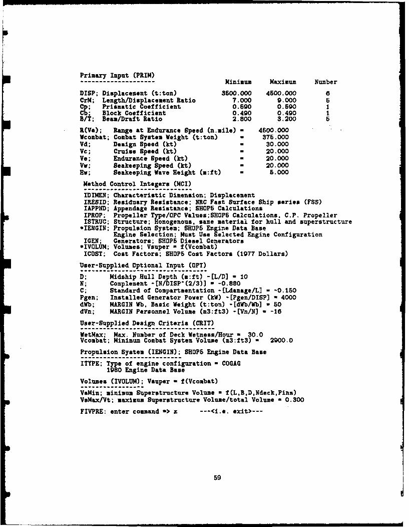
Primary Input (PRIM)........... Minimum Maximum Number
DISP; Displacement (t:ton) 3500.000 4500.000 6CrM; Length/Displacement Ratio 7.000 9.000 5C9 Prismatic Coefficient 0.690 0.590 1
Block Coefficient 0.490 0.490 1BIT; Beam/Draft Ratio 2.800 3.200 6
R(Ve); Range at Endurance Speed (n.mile) 4500.000Wcombat; Combat System Weight (t:ton) 375.000Vd; Design Speed (kt) 30.000Vc; Cruise Speed (kt) 20.000Ve; Endurance Speed (kt) 20.000Vv; Seakeeping Speed (kt) 20.000Hw; Seakeeping Wave Height (m:ft) 5.000
Method Control Integers (MCI)
IDIMEN; Characteristic Dimension; DisplacementIRESID; Residuary Resistance; NRC Fast Surface Ship series (FSS)IAPPND; Appendage Resistance; SHOPS CalculationsIPROP; Propeller Type/OPC Values;SHOP5 Calculations. C.P. PropellerISTRUC; Structure; Homogenous. same material for hull and superstructure
*IENGIN; Propulsion System; SHOPS Engine Data BaseEngine Selection; Must Use Selected Engine Configuration
IGEN; Generators; SHOPS Diesel Generators*IVOLUM; Volumes; Vsuper a f(Vcombat)ICOST; Cost Factors; SHOPS Cost Factors (1977 Dollars)
User-Supplied Optional Input (OPT)
D; Midship Hull Depth (m:ft) -[L/D] - 10N; Complement -[N/DISP-(2/3)] - -0.880C; Standard of Compartmentation -[Ldamage/L] - -0.150Pgen; Installed Generator Power (kW) -[Pgen/DISP] a 4000dWb; MARGIN Wb. Basic Weight (t:ton) -[dWb/Wb] - 50dVn; MARGIN Personnel Volume (m3:ft3) -[Vn/N] - -18
User-Supplied Design Criteria (CRIT)
WetMax: Max. Number of Deck Wetness/Hour - 30.0Vcombat; Minimum Combat System Volume (m3:ft3) - 2900.0
Propulsion System (IENGIN); SHOPS Engine Data Base
ITYPE; Type of engine configuration w COGAG1980 Engine Data Base
Volumes (IVOLUM); Vauper - f(Vcombat)
VsMin; minimum Superstructure Volume a f(L,B.D.Ndeck.Pins)VsMax/Vt; maximum Superstructure Volume/total Volume - 0.300
FIVPRE: enter command -> z ---<i.e. exit>---
59
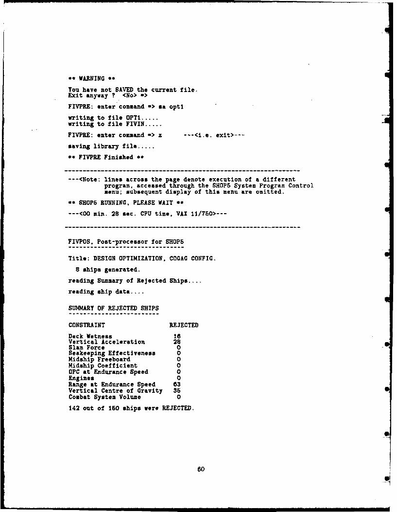
** WARNING **
You have not SAVED the current file.
Exit anyway ? <No> ->
FIVPRE: enter command -> &a optl
writing to file OPT1 .....writing to file FIVIN .....
FIVPRE: enter command -> z ---<i.e. exit>---
saving library file .....
** FIVPRE Finished **
---<Note: lines across the page denote execution of a differentprogram. accessed through the SHOP5 System Program Controlmenu; subsequent display of this menu are omitted.
**SHOPS RUNNING. PLEASE WAIT **
---<00 min. 28 sec. CPU time. VAX 11/750>---
FIVPOS. Post-processor for SHOPS
Title: DESIGN OPTIMIZATION. COGAG CONFIG.
8 ships generated.
reading Summary of Rejected Ships ....
reading ship data....
SUMMARY OF REJECTED SHIPS
CONSTRAINT REJECTED
Deck Wetness 18Vertical Acceleration 28Slam Force 0Seakeeping Effectiveness 0Midship Freeboard 0Midship Coefficient 0OPC at Endurance Speed 0Engines 0Range at Endurance Speed 63Vertical Centre of Gravity 36Combat System Volume 0
142 out of 150 ships were REJECTED.
60S

COMMAND MENU
1 SELECT PARAMETER2 Re-plot3 Define Window4 Select Ships for Lineprinter5 Select Ships for Transfer to FIVPRE6 Summary of Rejected Ships7 Define Terminal Type8 HELP9 EXIT
Enter selection => 1
PARAMETER CATEGORIES
1 Primary Input2 Dimensions and Complement3 Geometric Ratios and Coefficients4 Cost6 Range6 Weight Components7 Volume Components8 Stability9 Seakeeping10 Resistance and Propulsion
Enter selection <exit> => 5
Range
27 R(Vd) Range at Design Speed28 R(Vc) Range at Cruise Speed29 R(Ve) Range at Endurance Speed30 R(M) Mission Range31 R(Vd)/Wf Range at Design Speed/Fuel Weight32 R(Vc)/Wf Range at Cruise Speed/Fuel Weight33 R(Ve)/Wf Range at Endurance Speed/Fuel Weight34 R(M)/Wf Mission Range/Fuel Weight
Enter selection <exit> => 27
PARAMETER DEFINITION
1 PLOT2 Divide By:3 Select Another Parameter4 Show Selected Parameters5 Reset Selected Parameters6 HELP
Enter selection <exit> -> 1
--- <see Figure 4 in the main text>---
---<Notes: - All subsequent references to the FIVPOS menus shownabove are omitted.
- See Appendix E for a listing of the FIVPOS parameters.- Subsequent graphs for these ships are Figure 5 in themain text and Figures C.1 through C.3

---<on COMMAND menu, select Transfe'% Ships>---
SELECT SHIPS FOR TRANSFER TO FIVPRE
To select individual thips. enter each SHIP NUMBER ona separate line.
To select a range of ships, enter two SHIP NUMBERS onthe same line, separated by a blank or comma.Enter SHIP NUMBER(S) <exit> -> 8Enter SHIP NUMBER(S) <exit> =>
---<on COMMAND menu, select Exit>---
writing Summary of Rejected Ships to lineprinter .....saving graphs for Re-Plot command .....saving ships for FIVPRE .....
** FIVPOS Finished **
FIVPRE. Pre-processor for SHOP5
reading library file .....
reading ships from FIVPOS .....
Primary Input (PRIM), Geometry ---<automatic display>---
Disp 4500.0CrM 8.50Cp 0.690Cb 0.490B/T 3.200
FIVPRE: enter command a> c mode --- <i.e. CHANGE MODE>---
MODE
0 SEARCHI DESCRIBE
MODE ? <SEARCH> ->
Mode Change: DESCRIBE to SEARCH
I Restore most recent SEARCH mode file2 Select DESCRIBE mode ship to initialize search space3 Define search space from scratch.4 Cancel mode-change
Enter selection <Restore SEARCH> -> 2
Rv(e); Range at Endurance Speed -> 4500
62"S

Primary Input (PRIM)-------------------- Minimum Maximum Number
DISP; Displacement (t:ton) 4500.000 4600.000 1CrM; Length/Displacement Ratio 8.500 8.500 1Cp; Prismatic Coefficient 0.590 0.590 1Cb; Block Coefficient 0.490 0.490 1B/T; Beam/Draft Ratio 3.200 3.200 1
R(Ve); Range at Endurance Speed (n.mile) a 4500.000Wcombat; Combat System Weight (t:ton) a 376.000Vd; Design Speed (kt) a 30.000Vc; Cruise Speed (kt) a 20.000Ve; Endurance Speed (kt) * 20.000Vv; Seakeeping Speed (kt) * 20.000Hv; Seakeeping Wave Height (m:ft) 6 5.000
FIVPRE: enter command -> c crmMinimum Maximum Number
CrM; Length/Displacement Ratio 8.500 8.500 1
CrM; Length/Displacement Ratio Minimum => 8Maximum -> 8.5
Number of values => 6
FIVPRE: enter command -> c cp Minimum Maximum Number
Cp; Prismatic Coefficient 0.590 0.590 1
Cp; Prismatic Coefficient Minimum -> .57Maximum W> .61
Number of values => 3FIVPRE: enter command => c cb
Minimum Maximum Number
Cb; Block Coefficient 0.490 0.490 1
Cb; Block Coefficient Minimum -> .47Maximum => .51
Number of values -> 3
FIVPRE: enter command > b/tMinimum Maximum Number
B/T; Beam/Draft Ratio 3.200 3.200 1
B/T; Beam/Draft Ratio Minimum => 2.8Maximum => 3.2
Number of values => 5
FIVPRE: enter command -> ia ---<i.e. SAVE>---
Enter FILE NAME <FIVIN only> a>
writing to file FIVIN .....
63
, i II - P

FIVPRE: enter command -> z
saving library file .....
** FIVPRE Finished **
** SHOP5 RUNNING. PLEASE WAIT **
---<00 min. 57 sec CPU time, VAX 11/750>---
FIVPOS, Post-processor for SHOPS
Title: DESIGN OPTIMIZATION. COGAG CONFIG.
105 ships generated.
reading Summary of Rejected Ships....
reading ship data.... 10 20 30 40 50 60 70 80 90 100
SUMMARY OF REJECTED SHIPS
CONSTRAINT REJECTED
Deck Wetness 0Vertical Acceleration 0Slam Force 0Seakeeping Effectiveness 0Midship Freeboard 0Midship Coefficient 90OPC at Endurance Speed 0Engines 0Range at Endurance Speed 0Vertical Centre of Gravity 75Combat System Volume 0
165 out of 270 ships were REJECTED.
COMMAND MENU
1 SELECT PARAMETER2 Re-plot3 Define Window4 Select Ships for Lineprinter5 Select Ships for Transfer to FIVPRE6 Summary of Rejected Ships7 Define Terminal Type8 HELP9 EXIT
Enter selection -> 2 ---<i.e. Re-Plot>---
64
- -- " | i F i " 9

Parameter (s)
I FC(Vc) Fuel Consumption. Cruise Speed2 Vsuper Superstructure Volume3 CrM Length/Displacement Ratio (Circle M)4 P.A. $ Platform Acquisition Cost (lead ship)5 R(Vd) Range at Design Speed8 GM/B Metacentric Height/Beam7 Pins Total Installed Power8 Vmax(w) Maximum Speed in Waves (limited by Pins only)9 R(Ve) Range at Endurance Speed10 KG/KGmax KG/maximum KG for Damaged Stability11 ..ratio (Vsuper) / (Vtotal)12 B/T Beam/Draft Ratio13 Cb Block Coefficient14 Cp Prismatic Coefficient15 DSP Displacement
Enter selection <exit> -> 5
---<see Figure C.4>------<on COMMAND menu, select Define Window>---
WINDOW DEFINITION
The window is defined by low and high ship numbers,corresponding to left and right sides of the window.
The window definition is preserved until reset.
Enter SHIP NUMBER: LOW -> 81,99
---<on COMMAND menu, select Re-Plot>------<on Re-Plot menu, select item I (most recent plot)>------<see Figure 7 in main text>------<on COMMAND menu, select Transfer Ships>---
SELECT SHIPS FOR TRANSFER TO FIVPRE
To select individual ships, enter each SHIP NUMBER ona separate line.
To select a r..ge of ships, enter two SHIP NUMBERS onthe same line, separated by a blank or comma.
Enter SHIP NUMBER(S) <exit> -> 90,92Enter SHIP NUMBER(S) <exit> a>
---<on COMMAND menu, select Exit, omit exit messages>---
** FIVPOS Finished **
FIVPRE. Pre-processor for SHOPS
reading library file .....reading ships from FIVPOS .....
65
• , Mmmmnm mum m /nilel / W 'mamI

Primary Input (PRIM). Geometry ---<automatic display>---
SHIP 1 2 3[90] [91] [92]
Disp 4600.0 4600.0 4600.0CrM 8.40 8.40 8.60Cp 0.610 0.610 0.570Cb 0.490 0.510 0.470B/T 3.200 3.200 3.200
FIVPRE: enter command a> c mode
MODE
0 SEARCHI DESCRIBE
MODE ? <SEARCH> -> ---<i.e. Return only - SEARCH mode>---
Mode Change: DESCRIBE to SEARCH
1 Restore most recent SEARCH mode file2 Select DESCRIBE mode ship to initialize search space3 Define search space from scratch.4 Cancel mode-change
Enter selection <Restore SEARCH> -> 2
Which ship ? Enter SHIP NUMBER or ? <exit> -> 2
Rv(e); Range at Endurance Speed -> 4500
Primary Input (PRIM) ---<automatic display>---
Minimum Maximum Number
DISP; Displacement (t:ton) 4500.000 4500.000 1CrM; Length/Displacement Ratio 8.400 8.400 1Cp; Prismatic Coefficient 0.610 0.610 1Cb; Block Coefficient 0.510 0.510 1B/T; Beam/Draft Ratio 3.200 3.200 1
R(Ve); Range at Endurance Speed (n.mile) - 4500.000Wcombat; Combat System Weight (t:ton) a 375.000Vd; Design Speed (kt) - 30.000Vc; Cruise Speed (kt) - 20.000Ve; Endurance Speed (kt) - 20.000Vv; Seakeeping Speed (kt) - 20.000Hw; Seakeeping Wave Height (m:ft) - 5.000
FIVPRE: enter command -> c crm
---<omit re-definition of ?rimary Input, new values shown below>---
66
• • .. .. ,,..mm-m--m -----.-- m mmm i m imm m~k~qm mmm -

Minimum Maximum Number
DISP; Displacement (t:ton) 4520.000 4560.000 3CrM; Length/Displacement Ratio 8.350 8.450 3Cp; Prismatic Coefficient 0.590 0.620 3Cb; Block Coefficient 0.500 0.520 3B/T; Beam/Draft Ratio 3.100 3.300 3
FIVPRE: enter command -> sa ---<i.e. SAVE>---
Enter FILE NAME <FIVIN only> ->
writing to file FIVIN .....
FIVPRE: enter command -> z
** FIVPRE Finished **
** SHOPS RUNNING, PLEASE WAIT **
---<00 min. 54 sec. CPU time. VAX 11/750>---
FIVPOS, Post-processor for SHOPS
Title: DESIGN OPTIMIZATION. COGAG CONFIG.
129 ships generated.
reading Summary of Rejected Ships....
reading ship data.... 10 20 30 40 50 60 70 80 90 100110 120
SUMMARY OF REJECTED SHIPS
CONSTRAINT REJECTED
Deck Wetness 0Vertical Acceleration 0Slam Force 0Seakeeping Effectiveness 0Midship Freeboard 0Midship Coefficient 81OPC at Endurance Speed 0Engines 0Range at Endurance Speed 0Vertical Centre of Gravity 33Combat System Volume 0
114 out of 243 ships vere REJECTED.
---<End of Appendix C>---
0
67

0
g. 0 I p p
-8. 5 -
W8.0 -U
o.7.5
0%-.7.0
C-6.5 1w 0 2 4 6 a 10
SHIP NUMBERS
Figure C.1: Length Displacement Ratio, First-Run Ships
aS5000, , , ,
w
04000
w
3000
cc
w 2000Dn 0 2 4 6 a 10u SHIP NUMBERS
Figure C.2: Superstructure Volume, First-Run Ships
68

3.2 '
(flW
nw
C. 2.6
24 0 2 4 6 a to II
z00
wwj02300-
z
wU)22000
~2100Cr 0 20 40 60 B0 100 120
SHIP NUMBERS
Figure 0.4: Range at Design Speed, Second-Run Ships
69

Appendix D: Design Optimization Example, Session 2
The trends shown in Appendix C lead towards the design candidate selected in this ap-pendix. The relative merits of this ship are illustrated by examining FIVPOS graphics andlineprinter output. The SHOP5 DESCRIBE mode lineprinter output for this ship is alsoincluded.
This terminal session is presented using the same format as Appendix C.
FIVPOS. Post-processor for SHOP5
Title: DESIGN OPTIMIZATION. COGAG CONFIG.
83 ships generated.
reading Summary of Rejected Ships....
reading ship data.... 10 20 30 40 50 60 70 80
SUMMARY OF REJECTED SHIPS
CONSTRAINT REJECTED
Deck Wetness 0Vertical Acceleration 0Slam Force 0Seakeeping Effectiveness 0Midship Freeboard 0Midship Coefficient 54OPC at Endurance Speed 0Engines 0Range at Endurance Speed 0Vertical Centre of Gravity 79Combat System Volume 0
133 out of 216 ships were REJECTED.
COMMAND MENUI SELECT PARAMETER
2 Re-plot3 Define Window4 Select Ships for Lineprinter5 Select Ships for Transfer to FIVPRE6 Summary of Rejected Ships7 Define Terminal Type8 HELP9 EXIT
Enter selection => 2
70

Parameter(s)
I P.A. $ Platform Acquisition Cost (lead ship)2 CrM Length/Displacement Ratio (Circle M)3 GM/B Metacentric Height/Beam4 R(Vd) Range at Design Speed5 FC(Vc) Fuel Consumption. Cruise Speed6 Vauper Superstructure Volume7 Pins Total Installed Power8 Vmax(w) Maximum Speed in Waves (limited by Pins only)9 R(Ve) Range at Endurance Speed10 KG/KGmax KG/maximum KG for Damaged Stability11 ..ratio (Vsuper) / (Vtotal)12 B/T Beam/Draft Ratio13 Cb Block Coefficient14Cp Prismatic Coefficient15 D6P Displacement
Enter selection <exit> -> 4
---<see Figure D.I>------ <Define Window for ships 61 to 79 and then Re-Plot>------<see Figure D.2>------<Transfer Ships 69, 70 and 71 to FIVPRE>------<Exit from FIVPOS. omit exit messages>---
FIVPRE. Pre-processor for SHOP5
reading library file .....reading ships from FIVPOS .....
Primary Input (PRIM). Geometry ---<automatic display>---
SHIP 1 2 3[89) [70] [71)
Disp 4620.0 4620.0 4620.0CrM 8.35 8.35 8.35Cp 0.695 0.595 0.595Cb 0.505 0.505 0.505B/T 3.150 3.150 3.150
FIVPRE: enter command -> c mode
---<omit re-definition of Primary Input, new values shown below>---
Minimum Maximum Number
DISP; Displacement (t:ton) 4620.000 4620.000 1CrM; Length/Displacement Ratio 8.350 8.450 3Cp; Prismatic Coefficient 0.585 0.595 3Cb; Block Coefficient 0.495 0.505 3B/T; Beam/Draft Ratio 2.950 3.250 7
71

FIVPRE: enter command -> sa ---<i.e. SAVE>---
--- <omit SAVE and EXIT from FIVPRE>---
** SHOP5 RUNNING. PLEASE WAIT **
---<00 min. 39 sec CPU time. VAX 11/750>---
FIVPOS. Post-processor for SHOP5
Title: LONG COGAG
58 ships generated.
reading Summary of Rejected Ships....
reading ship data.... 10 20 30 40 50
SUMMARY OF REJECTED SHIPS
CONSTRAINT REJECTED
Deck Wetness 0Vertical Acceleration 0Slam Force 0Seakeeping Effectiveness 0Midship Freeboard 0Midship Coefficient 63OPC at Endurance Speed 0Engines 0Range at Endurance Speed 0Vertical Centre of Gravity 88Combat System Volume 0
131 out of 189 ships were REJECTED.
--- <omit FIVPOS menus>------<see Figure 7 in main text and Figures D.4 through D.7>------<select ships 18 to 24 for lineprinter output, see Table D.I>------ <select ship 20 for transfer to FIVPRE>------ <omit Exit from FIVPOS>---
FIVPRE, Pre-processor for SHOP5
reading library file .....
reading ships from FIVPOS .....
72
p

Primary Input (PRIM). Geometry --- <automatic display>---
Disp 4620.0CrM 8.35C 0.595
0.605B/T 3.150
FIVPRE: enter command -> c tit ---<i.e. CHANGE TITLE>---
Enter TITLE -> long cogag
FIVPRE: enter command -> sa sl --<i.e. SAVE (as file) S1>---
writing to file S1 .....writing to file FIVIN .....
FIVPRE: enter command -> z
saving library file .....
** FIVPRE Finished **
** SHOP5 RUNNING. PLEASE WAIT **
---<00 min. 05 sec CPU time>---
---<see Table D.2 for SHOP5 DESCRIBE mode ouput on this ship>---
--- <End of Appendix D>---
II
73
IL
. ... . ,...,. ... ,-- m-., n. m uu m m llm m m m mm n

. .. . .C . .e .I
10 C.
41 041 ,
0 C4M
*~ 0
00 I 1 1 -10 I's 0ft 0 '
to Is -,,w
ON~~ E* I= 10001 I
m 6N
...... .....
N I I I 74

C, 0% 0 O 0 O 0 N0.4N4 CO,~L co 0W4f4.-.40C0 .41 NWoo.0U4040. 0-.N.O 4>O C9 UUomO1.
N e0. 0-. O0'N- M C,00' C4~ 40 .0 .C 4 aD 1u V n DNC> Ime ~44 )_ O l 0 r' - - 04.4 It N N IDO e-
0qN . 0 .%f . .. 00 .4 .4 0 . . 0 N 4.4 044. 04! 1 4 0 1! 4 40o44~ OO1 l0N c00 qm4. 4 1 ILA-4N. MON 0o.4o%o"CD 14 LNO0n o. 8D u~ o ccr-
N V *44- .-4U 40 m F: 4.n A rA .0 04. e) 4 M 4 V 0 en LUn zIVm40i *44 *N-.4%- on -4 CD (n r N N m I
,4 " V
ONO 0m14001 R NLA SN .400
V 0 N w coNO. en0.-4-40r
0 NO .4~0 .4.4 .- 4 LA 0 C, .N
141
0 ! . T C ! i 0 l 1 1 4 0 0. . - N f .- 0 ..4 0 1 ! 0 % 0 N 4 ) 0 0 0 - 0 C , a , C 1C ! C !4 r r M C r l < :L ) 0 LO0 -toONLA0%00 ocv %-: mo 0 410o M0% J .4 . M0 -4 NN 1 444 4.01.400 010N0M " M0o Do t L4nN49.9' 40N
N4 N4.44 .44.4r, i oO4L r- Onu 14 O LnU4 .- 1 o1 c4 qw Zv LA In V LAn -I-T1
-4 -4 V.-
%DN o0 , 0 L n t01 o -4 0 -c4i =NA0 . - 40 o fnMo -(V% A014 f4 IV.0 .. .NL. -0 . . N 414 m
N4 e nm.4 .- N NO in Nn rO o0.4 o4 LA ONr,0 40 AC4 r 0n fn44.0. N0N.4 . 414 w wm V . N wn
-4 -4 (n Ln m 4 th i
C4 ON NOLAOLDN41 00 .0 -4 0. 00 ow001 4 4 1 ~4 n 10 0 0 0
C> Wff 4 o: OC I N OOO. -4 a, 14
-4 -4 ,
C4N-4 m 0o - O 4D00 0 0 v m f- v 4 0 0 1N O gN v LANm0 . 0 ' .LA m m 4. o o0M-400 UD -4 01. ONON .4oNloaO0OmcO1 por. =0141 c 0 dNO 0 N- 1N-44 N-01 44000 o 140-41 .D. 4100
00 LO0 /LA0%A N1 1014 0N04044 M0 4-0.0.401 4.401 .04(.-4-oN. -
c0 o0N- V 0 co00 a r%; N NLn r NLn Dmr 9 N LAO mw o % r %-i N..r.4 N.4.4 . NO NLA N *(4. N 414.O ~ ~ ONN0.4.-4-~LLANONN.04-4 .4m r144 C.404400%On0.440- w4 NN e) Nn N%D 0)C4 I M CM) V , teq 1
m4 -4 l -4N L A O
A S
-4 ~ 4 -4.4 *N ~~~ ~ ~ ~ 4 C~44 ~ I,.1 4. ~ 4
uf ****** R M E R.. ,-2 NM W
50 N4 J 4 4J4~J4 J&EEII~f _4 4' a~ W.C4 - ~ ~ *lU.~
1A4 .L 44iL
4~ ILW

a. a.. IC Ia aa a leaa I aOl
a I fla
a a a a
a a a aa ace *e aa a a aa a a a
a aC.aa a aa a aa a.. l.aa a I I IIa I I
a a aC.a a a aa~a a a a
a I I I aa a -a I I 04
a a a aaaflaa Cl a aaMtaOLa *1 a a a e
a a a C
a ~I lC.I I I a C.
I I I I a a I
* a I I I I a 0
a a.. l.a I Ia a a a a a a IIa a I a * I - a
V~~Ca Sa I t4 ~4~2 a IA
a a4.I~ a a* a a a a Ua all I a 04
a IN 101 a RC.
.4C. ..,a a
C. a a a a U
Kid lana ]~aJ3~W:
aS~aa a a
lana ~-4aCl lS2LJ 04
aol ~Ia~ II
EI~C. >. l.a
lana anan~aA~lt~
lea a ~Ja I I
a C.I.aa a a
lana aafla a a
a~aO I *I a aoooaoC.OC.-4C 1-4Ca a I
jZ a a I ,I a ~* ~:aa-aaO a a a I
dqtIII a a I a aCl a
aca a a
a 11.4 ana a I a
a a a~a ~a.4C.anaDCCOa a~lJ aaDl hiaa a I a a ~a ~a a a I I a aa.,.. a. a a ~a
76
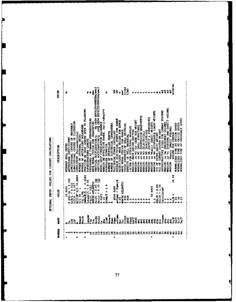
P IL
co a. -- F NX
a a I-U9a2lpa
ai11j n IL
aN - 000. t
w Z
V) a-a C/
a a' a I 0O
a 2~. iflu ' . u1
* 2, C2.~ C! 000 00
a ~~~~>O >- .a ~ ~ .o t
100~e~aJ0.-a0000 0000 0 '- 000 f:)w
- ~co~o...........77)
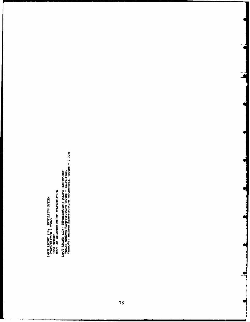
CD
Aj
a
78

0! V! -C!I 0 ll li N .i Ct1
2 ilt t ilt itti if i itIt i1in 0~I u u
C, CON C, ~ LA L"[CD. 00* wD .00 .41.!4
C;C C ftc f ,PCM 4
I i t 11 fi l 11 11 11 ii ii iA. 0.iUa.O a
In Ca. 4a4 C!rI,1 A%
In In *
I~ ~ It,%.. *a
U, 01 1. 0.001N
'n~l Let~0 C.N 02 -4 0 (0 C en C a
11 I It11 itillitilt 1 11 1111 I
m k 0 V0 ICC 0 C - c0C, 4 c
0 * I I C ; l .
N4' l 6a 4
5 1000
I 4 .l; 014 nI
79focl
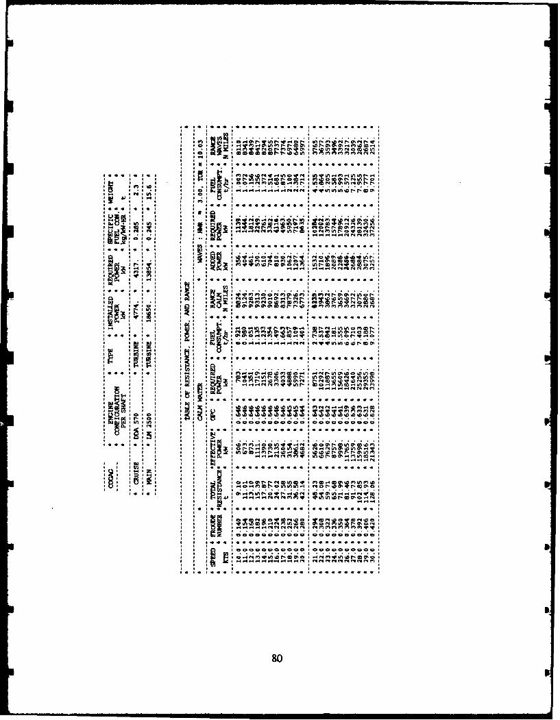
-I~ I 4 M 4 n r % 012O 0 I 0 , 4 r) CD
4. IC ~ I4 0 0 0 . 0 000..* . . .
I. InI 'I ZI 10 In CC
P) In I Ir c1
M4~ IN I I- in I U 10 M CoN C O 0Nt L
qUOl 010 IP r, OD 0 I I 4 O CNI4 rJr4 C4 I4 i I I
II-4 II. 301N M1 M(.0ON M 0 ON,*
In
4
I0
;1 An
XI I. InI I : ~ l I~ I-q(4cqqr Ctc DV, r1C )0
I ~ ~ ~ ~ ' ID 100 040 * 0 4 0 M*4 0 0
NilI I I
I, . ID mm
1.4 rn- Lo I * o D4 I; C; I; I; C;O4I2(I ~~~.4 O N4 Ifllf o . C.0lI 3 I f4I 1 qW n F 0 1 0 f O I 11 f 3 0 f ~ . O~
I ~ ~ ~ ~ ~ ~ ~ ~ C ... VI C11 I; ~ II00O4n~D.~ W . I O W
C! 1=bi= I C! I V! 9 !C
Ch0 I4 (n in I I V I 4 CI f- 4f 4
.I 4[IIl -4 [.4 I4 1! r! P! M
I ~ ~ ~ ~ f V. %A %0 fl CO M CO -4 C4 In r1..0.Oa1 In. %D f- 40 l 01 0
I I I 1(01 1.4 I0 .4If soMW 1 I ~ % I 4 N 3 )

z 2550.
w 2 5 0 0w'n2450z
n2400w2350-
Ui02300
o 20 40 60 s0SHIP NUMBERS
Figure DA1: Range at Design Speed
z I I I I 1 255
O2500w
un 2450zCD"2400w'2350 -- ,r-
2300
< 60 65 70 75 80SHIP NUMBERS
Figure D.2: Range at Design Speed, Ships 61 to 79
81

(,
0 T
I-4 237.9l
_j 10 20 30 40SHIP NUMBERS
Figure D.3: Metacentric Height/Beam Ratio, Final-Run Ships
X
w
wXC.1
I0. 0902030 40
SHIP NUMBERS
Figure D.4: Platform Acquisition Cost, Final-Run Ships
82

910
~900 r
w' 890-
IL
870UN10 20 3.....:0 40
SHIP NUMBERS
Figure D.5: Fuel Weight, Final-Run Ships
10.
ED
z (-
z
ILW
10 20 30 40SHIP NUMBERS
Figure D.6: Fuel Consumption at Design Speed, Final-Run Ships
83

137.5 , , ,, , , 1. . ,,, 51 , ,
zu~ti35.0-.4Enw 32. 5'}-4
w Ena:, 130.0
125.0
10 20 30 40SHIP NUMBERS
Figure D.7: Total Resistance at Design Speed, Final-Run Ships
84
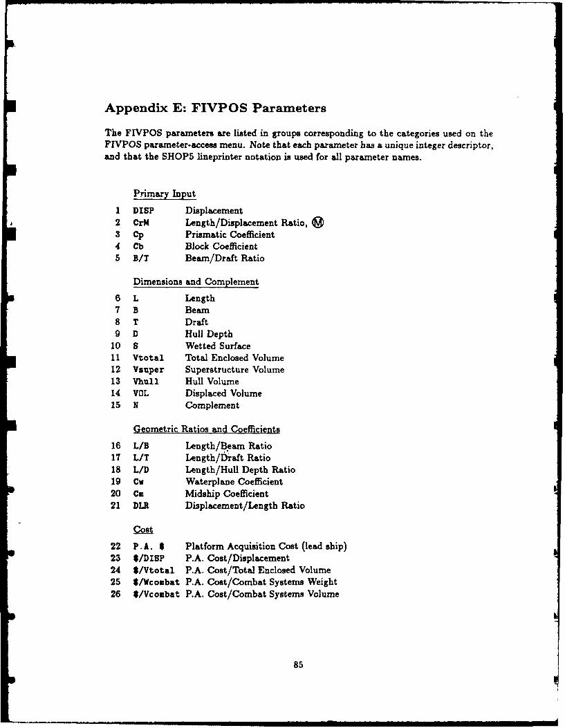
Appendix E: FIVPOS Parameters
The FIVPOS parameters are listed in groups corresponding to the categories used on theFIVPOS parameter-access menu. Note that each parameter has a unique integer descriptor,and that the SHOP5 lineprinter notation is used for all parameter names.
Primary Input
1 DISP Displacement2 CrM Length/Displacement Ratio, g93 Cp Prismatic Coefficient4 Cb Block Coefficient5 B/T Beam/Draft Ratio
Dimensions and Complement
6 L Length7 B Beam8 T Draft9 D Hull Depth
10 S Wetted Surface11 Vtotal Total Enclosed Volume12 Vsuper Superstructure Volume13 Vhull Hull Volume14 VOL Displaced Volume15 N Complement
Geometric Ratios and Coefficients
16 L/B Length/fleam Ratio17 L/T Length/Draft Ratio18 L/D Length/Hull Depth Ratio19 Cw Waterplane Coefficient20 Cm Midship Coefficient21 DLR Displacement/Length Ratio
Cost
22 P. A. $ Platform Acquisition Cost (lead ship)23 $/DISP P.A. Cost/Displacement24 $/Vtotal P.A. Cost/Total Enclosed Volume25 $/Wcombat P.A. Cost/Combat Systems Weight26 $/Vcombat P.A. Cost/Combat Systems Volume
85

Range
27 R(Vd) Range at Design Speed28 R(Vc) Range at Cruise Speed29 R(Ve) Range at Endurance Speed30 R(M) Mission Range31 R(Vd)/Wf Range at Design Speed/Fuel Weight32 R(Vc)/Wf Range at Cruise Speed/Fuel Weight33 R(Ve)/Wf Range at Endurance Speed/Fuel Weight34 R(M)/Wf Mission Range/Fuel Weight
Weight Components
35 WI Structure Weight36 W2 Propulsion System Weight37 W3 Electrical Systems Weight38 W5 Auxiliary Systems Weight39 W6 Outfit and Furnishing Weight40 Wd Disposable Loads Weight41 Wf Fuel Weight42 Wcombat Combat Systems Weight
Volume Components
43 Vm Machinery Volume44 Vn Personnel Volume45 Vo Outfit and Systems Volume46 Vf Fuel Volume47 Vcombat Combat Systems Volume
Stability
48 GM Metacentric Height49 GM/B Metacentric Height/Beam50 GMf Fluid Metacentric Height51 G /B Fluid Metacentric Height/Beam52 KG Vertical Centre of Gravity53 KG/D Vertical Centre of Gravity/Hull Depth54 KG/KGmax KG/maximum KG for Damaged Stability55 Tau Natural Roll Period (unappended)
86

Seakeeping
56 Nwet Number of Deck Wetnesses57 Accn RMS Vertical Acceleration/g at Station 458 Falam Slam Force/Displacement59 S (Ef) Crew Seakeeping Effectiveness
Resistance and Propulsion
60 Rt (Vd) Total Resistance, Design Speed61 Rt(Vc) Total Resistance, Cruise Speed62 Rt (Ve) Total Resistance, Endurance Speed63 OPC(Vd) Overall Propulsive Coefficient, Design Speed64 OPC(Vc) Overall Propulsive Coefficient, Cruise Speed65 OPC(Ve) Overall Propulsive Coefficient, Endurance Speed66 FC(Vd) Fuel Consumption, Design Speed67 FC (Vc) Fuel Consumption, Cruise Speed68 FC(Ve) Fuel Consumption, Endurance Speed69 Pins Total Installed Power70 Pmain Installed Power of Main Engines71 Pcruise Installed Power of Cruise Engines72 Vm/Pins Machinery Volume/Total Installed Power73 Vmax(w) Maximum Speed in Waves (limited by Pins only)74 e Transport Effectiveness75 SP Specific Power
87
,., .ee , .ea ,,,m-,.,,,,.,..-, mm asa i i m tn i o
REFERENCES
1. Colwell, J.L.: "Technology Base Manual for the SHOP5 System: A Concept Explo-ration Model for Monohull Frigates and Destroyers", DREA Technical Memorandumin review.
2. Eames, M.C. and Drummond, T.G.:"Concept Exploration - An Approach to SmallWarship Design", RINA Trans., Vol. 119, 1977.
3. Anderson, R.J. and Schrnitke, R.T.:"A Concept Exploration Model for SWATHShips", DREA Technical Memorandum 79/I, December 1979.
4. Jones, E.A.:"A Concept Exploration Model for Hydrofoil Ships", DREA TechnicalMemorandum 81/B, August 1981.
5. Tremills, J.A. and Piggott, S:"Users Guide for ACVSES: A Concept Model for ACVand SES", DREA Informal Communication.
6. Lee, B., Colwell, J.L. and Godreau, P.V.:"FIVPRE: A Pre-Processor for the ConceptExploration Model SHOP5", DREA Technical Communication 85/310, August 1985.
7. Hockenberger, W.A.:"Ship Design Margins - Issues and Impacts", Naval EngineersJournal, Vol. 88, No. 2, April 1976.
8. Colwell, J.L.:"SHOP5 System Installation Guide", DREA Technical Communication87/301, January 1987.
9. Kehoe, J.W., Graham, C., Brower, K.S. and Meier, H.A.: "Comparative Naval Ar-chitecture Analysis of NATO and Soviet Frigates - Part 1", Naval Engineers Journal,Vol. 92, No. 5, October 1980.
10. Colwell, J.L.:"Effects of Length on Warship Design", DREA Report 85/104, August1985.
88

UNCtLASSTFTED
K*I jF. r- c.1. b~CAiTVI OF IOF0A
DOCUMEH' ,. ' IROL DATA
(Beey c~luicti, of tWtle. body of ab~aet. and indeting anmett Mat beuoged ufte the geol daaummut We cei"ood)
1. ORGINATOR (the etet and adde" of go hrganizat ptSPafttheUr domeMInt. 2 SECURMITY CLASSFCATION (emerci mclOgeunbkm f loth h the demont a sU preparetd e.. EeNWIsloniot epoenwing a demebon at the dooament. Wlddudinomtieo'uG po r wU.Iehrme q . we in s etion S.) speci ul teMa If pplieble)
3 TITLE (o eompble doaune U e as Idicaed n o title pW ft do retiao Should be ndiced by 1e appueprde(S.C.R ivU) In pateeiheee off e t tbe.)
USERS MANUAL FOR THE SHOP5 SYSTEM: A Concept Exploration Modelfor Monohull Frigates and Destroyers
4. AUTHORS (Last nue. Neat non. dddle NMii y. shw md6'. e.. Dee. Maj. John E.
Colwell, James L.
& DATE OF PUBLICATION (Oth and yew of pubicm id damwietr NO. OF PAGES (lo drawtong 6b. NO OF REFS (owel clied ink ormaion Indude Anneme, document)
November 1988 I e" ,at..) 97 10
6. DESCRIPTIVE NOTES (tho €oegary of the docuet. e.g. sechiceJ rpot. imchnie now or menorandum. II a mpng. he tho 0upor. c.. Ierim progres . suetury. annual or final. Give the lohidue dete when a epeciic vepatg Period iseered.)
Technical Communication
.SPONSORNG ACTIVITY (the nair o the dopement Project oim or Wbondary seonet" the rerteaeh and develorret t Inalude theeddress.)
9,PRJE-CT OR GRANT NO. - d aperpnte. the appisoeb reewd, ed b. CNTRACT NO. (U I ppopnee the apic"l numw underdevelapoent pro*% or grant nurvter under hal the document m which the domeit mm w trtisten. Pleaeo epecaly whether proj or grant
IOL ORIGINATOR'S DOCUMENT NUMBER (the h d docntent IOb. OTHER DOCUMENT NOS. (my ethern whih nwy benio.br by which the doeumet b identiied by the riksiaing meigned this doasent eiher by the ouflgkg or by theadity. This nuodee must be ulqu6 to this docmment.) eo
DREA Technical Communication 88/302
11. DOCUMENT AVAILABILITY (any Wriltione an further dieverniwdton d h. docmes. ether M th e by eeuyclassification)
PCX ) Unlieied iebboAn( ) Ditrbuton Wntted to deofece depeimeets and defemn oonrad"; 0tuder diotrlbuti o me epp( ) Dtstrbtii lirlted to delene depertmwt end Catrie0n do! -e c nlrastoe: fwutw diorkutiont e ad poved
Ototrwearo ed to goamuihlt depa tuiw and qgeeIe; fther disirbititon oa* an Mpaw( ) Diiittn Iinked to defence depeurtant; lher dbtlu enty b n a a e
~Othw ~obapewi:12.. DOCUMENT ANNOUNCEMENT (mny lh dation to the bh ogrephlc anneseceeil of this docmomst. This will 0omlly corepond to the
Dome Availibiiy (11). Hoevoer. who utdhe diatrbiton (beod the adienio epedied ie 11) iO pnoWIeo a wader aenoulunaidience o ey be sletded)
UNCLASSIFIED
SECURY CLAIMFICATION OF FOROG8in 90SI7
89

UNCLASSIFIEDUI~cTY CLAILSIFICATIOhI OF POW
13. ABSTRACT I o brief low ton* amyor of she dacuiw. ft lw miss opeor assiewe mi ft bodly ofis. doctmm ,tself. It is hghyasirelil 111 sli allimct of elswfieg docuinft k b e asfie Each WqrloIt of #4 shiri oll bag. Wi*ait a as SIM el fsevea calem~a of ft .forwaae 0 she owaipohIonailanshe decniS itself a vilesifiaed tgpiss~ a W. 10. ). or U.fIot 00wy M 1111 bare 111101i A bed IS 01 80f.?t busAM N ill NO 18 i behous?.
The SHOPS System is a computer-aided ship design tool for monohull frigate and destroyerConcept Exploration. Its primary application is to initialize the new-ship design process bydetermning the ship size, hull form and major systems best suited for the design require-ments. Other uses include evaluating new technologies and performing specific parametricstudies. The SHOPS System incorporates three major FORTRAN programs in a closed-loop system; program FIVPRE for defining and modifying ship descriptions and designrequirements, program SHOPS for computing ship characteristics, and program FIVPOSfor examining design candidates using computer graphics. Design calculations include sea-keeping in head seas, resistance, powering and range in calm water and in waves, propulsionand electrical system modeling, distribution of weight and volume components, preliminaryintact and damaged stability analysis, and platform acquisition cost. Platform feasibility isassessed by user-definable design criteria which define goals for performance and capability.The SHOPS ship description and design methodology are sufficiently flexible to define andanalyse a wide variety of ship geometries, systems and missions. Most input parametershave pre-programmed, default values representative of contemporary NATO practice anda variety of internal methods are available for many design calculations. All default valuesand most calculations can be modified or replaced by user-supplied input.14. KEYWORDS. DESCRIPTORS or DEWfFIERS ftochmesity too oqful ios I hor it Wes, Sn? cluowocile a doue~? Nid could be
helpful in catalouig to decutrn They shouald be selectd so dt po satwity clusica,,en is required Idemifiers. such as equigmmodel designation. trae nwie. iniliy prefect cede gi". poprohic loctio m"y also be wcludal, if possible keywwtds should be selectedfromn a puihed ithesimaus. a.ii Thesms of Enineetring widl Scienific Torms MlST) id Viot thsius-demifiedV if lis mia possible to11le1M odemog11i W11111 Whith 111 Unclaesf md. a. CtmSifciom Sf each Should be Wndcatd a With go tit.)
SHOP5Naval ArchitectureComiputer-Aided Ship Design (CASD)Concept Exploration Model (CEM)Feasibility DesignWarshipFrigateDestroyer
UNCLASSIFIED
MCLOTY Ct.AS1111ICATION OF FORMe
90