distribution restriction statement...once, only the last test result or last set of test results...
TRANSCRIPT

CECW-EG
Engineer Regulation
1110-2-1925
Department of the ArmyU.S. Army Corps of Engineers
Washington, DC 20314-1000
ER 1110-2-1925
3 July 1969
Engineering and Design
FIELD CONTROL DATA FOR EARTH ANDROCKFILL DAMS
Distribution Restriction StatementApproved for public release; distribution is unlimited.

Basic Reprint with change 1 & 2 Included.
THIS CONSTITUTES CHANGE 2 TO ER 1110-2-1925, 3 JULY 1969 This change entirely supersedes Change 1, 14 April 1970
ENGCW-ES
Regulation
DEPARTMENT OF THE ARMY Office of the Chief of Engineers
Washington, D.C. 20314
No. 1110-2-1925
ENGINEERING AND DESIGN Field Control Data for Earth and Rockfill Dams
(RCS ENGCW-E-11 (Rl))
ER 1110-2-1925 Change 2
20 August 1971
3 July 1969
* 1. Purpose. This regulation prescribes responsibilities and procedures for reporting field control data for earth and rockfill dams. *
2. Applicability. The reporting procedure described herein applies to all divisions and districts engaged in the construction of earth and rockfill dams.
* 3. Policy. As required by EM 1110-2-2300, Earth and Rock-Fill Dams -General Design and Construction Considerations, a complete construction record of a dam will be kept for use in construction, operation, and maintenance of the project. These records provide useful data for designing alterations and additions to the structure or aiding in determining causes of operating difficulties. Included in these records are data on methods of compaction, in-place unit weight and moisture content, piezometers, surface monuments, and slope indicators. *
* 4. Procedure for Reporting. During construction of the drun, all control data will be summarized at the end of each month on the ENG Forms shown in Appendix I. Since these forms may be used to tabulate the daily field control data, it is necessary only to reproduce a copy to forward to the District. Data on ENG Forms 4287, 4287A, 42878 and on ENG Forms 4076, 4077, 4078, 4079, 4080, and 4081 will be forwarded by the District to Division offices. *
This regulation rescinds ER 1110-2-1925 dated 31 July 1967
1

ER 1110-2-1925 3 July 1969
5. Use of Forms. The ENG form£ in Appendix I were developed after an analysis of the various field control data forms in use throughout the Corps. Instructions for completing the fo~ are outlined at the bottom of each form; supplementary instructions are given in Appendix II. While these forms are designed to permit recording of appropriate data for any type of dam, there may be situations where it is not necessary to use all columns. To prevent duplication, use of local forms in lieu of these standard ones should be discou~aged, unless special circtmletancee indi-:ate that local fonns are more appropriate. However, the division or district may require additional presentations such as gradation curves or graphical summaries of the in-situ embankment water content as related to optimum water content. The information outlined in Appendix III should be submitted with the initial report or whenever changes arc made.,
FOR THE CHIEF OF ENGINEERS:
3 Appendices App I Reporta Forms App II Supp Inst~uctions
for Report Forms App III Data to be Furnished
with Initial Report
2
~f.~ Colonel, Corps of Engineers Executive

Appendix I
Report Forms for Field Control Data for Earth and Rockfill Dams
ER 1110-2-1925 3 July 1969
The following forms are to be used in reporting field control data to the U.S. Army Engineer Waterways Experiment Station:
1. Summary of Field Compaction Control of Impervious or Semipervious Soils for Civil Works Projects (ENG FORM 4080)
2. Summary of Field Compaction Control of Pervious Soils and Rockfill for Civil Works Projects (ENG FORM 4081)
3. Closed-System Piezometer Data for Civil Works Projects (ENG FORM 4076)
4. Open-System Piezometer Data for Civil Works Projects (ENG FORM 4077)
5. Subsurface Settlement Plate Data for Civil Works Projects (ENG FORM 4078)
6. Surface Reference Point Data for Earth and Rockfill Dams (ENG FORM 4079)
7. Periodic Summary of Field Compaction Control Data (ENG FORMS 4287, 4287A, 4287B)

Appendix II
Supplementary Instructions for Report Forms
ER 1110-2-1925 3 July 1969
A. SUillllary of Field Compaction Control of Impervious or Semipervious Soils for Civil Works Pro3ects
Column
3
4
5
6
10
14 & 15
16 & 18
17 & 19
20
Title
Project
Report No.
Type Test
Station
Offset
Elevation
Class. Word or Letter Symbol
Atterberg Limits
Dry Density (pcf)
Water Content (%)
Test
Instructions
Name of dam, feature (e.g. main embankment, dike) and section (e.g. cutoff trench, cofferdam, closure, etc).
Number the reports consecutively for a given project.
Indicate by code (as shown at bottom of form) the method used to determine in-place density.
Record to nearest foot.
Record to nearest foot
Record (to near~st foot) the elevation of surface of fill where test is made.
Record color of soil. Letter symbol must be in accordance with Urlfied Soil Classification System.
Record to nearest whole number (e.g. LL= 35, PI= 17).
Record to nearest tenth.
Record to nearest tenth.
Denote the correlative test or method used (e.g. enter (1-pt) for standard effort test, (RCM) for rapid control USBR method, (LL) for liquid limit correlation,(VS) for visual comparison).

ER 1110-2-1925 3 July 1969 App II
B. Summary of Field Compaction Control of Pervious Soils and Rockfill for Civil Works Projects
Column Title
Rock Description
Gradation
tinstructions
Each general type or class of rock used as rockfill should be described. The relative hardness of rocks should be described as outlined in plate 2 of EM 1110-1-1806, Presenting Subsurface Information in Contract Plans and Specifications.
Pertinent sieve sizes should be noted and units of percent passing in whole numbers.
C. Instructions for Preparing Periodic Summaries of Field Compaction Control Data on Earth and Rockfill Dams. ENG Forms 4287, 4287A and 4287B
1. Summaries of compaction control data are prepared at least monthly, using a tabular summary form (Incl 1) and two summary plots, one for soils requiring control of both water content and density (Incl 2) and one for soils requiring only density control (Incl 3).
2. The tabular summary form and an individual summary plot should be prepared for (a) significantly different materials (impervious, random, pervious, etc.) used in different zones of the embankment and (b) materials compacted by different equipment (e.g., impervious fill compacted by towed rollers and impervious backfill compacted by handoperated power tampers).
3. Examples for preparing the summaries are shown in Incls 1, 2, 3, and 4. Additional examples of certain entries for the tabular summary are given in Incl 5.
4. Use of the summary plot for materials requiring water content and density control is illustrated in Incl 2. TWo vertical lines are first drawn on the plot to show the limiting values of water content in percentage points from standard optimum. A horizontal line is drawn to show the desired or specified minimum percent of maximum standard dry density. The top margin and right side margin of the plot are marked to show the limiting values illustrated in Incl 2. The data are then plotted using symbols shown in the legend. Should an area be reworked more than once or reworked and retested more than
tAlso refer to instructions in Part A of this Appendix.
2
__ _/

ER 1110-2-1925 3 July 1969
App II
once, only the last test result or last set of test results should be plotted. The test results are summarized in the tabulation form on the right side of the plot in Incl 2. Total number of tests is the total number of plotted data points. Check tests should not be included in the number retested.
5. Use of the summary plot for materials requiring only density control is illustrated in Incl 4. The inappropriate labels at the top and bottom of the plot are lined out. If the maximum density is determined using a vibratory procedure, "STD" should also be lined out. Suitable scales are added to the plot, and a vertical line is drawn to indicate the minimum value of relative density, minimum percent of maximum standard dry density, or minimum percent of maximum dry density by a vibratory procedure, whichever applies.
5 Incl
3

E!~ 1110-?-1925 3 July 1969 App li
PERIODIC SUMMARY OF FIELD COMPACTION CONTROL DATA
Project Example Dam Resident Engr s. J, Smith District District Insp. or Tt>ch J. s. Jonn Location of Project Sunflower River, WP.hstP.r, Miss. Report No 12 Period 5 Nov 68 to 5 Dec ·68
TYPE OF FILL IMPERVIOUS (CORE)
Soil Classification (USCS Symbols) CH, CL
Stationing of Areas Tested 14+75 to 4<3+.)0
Elevation of Areas Tested 832 to 840
Compaction Equipment SheepsCoot roller, Ferguson s~lf-propellnd modol SP-1208 ( 31_5 JlSi}
Number of Passes 8
juncomp. Lift Thick. 8 in,
!Roller Speed, MPH 3 to ~
In-Place Density Method Sand Volume (90%) (Give % of tests made Nuclear (10%)** ~ith each method) Method of Determining Oven Drying Field w Method of Re 1 at·; ng Field results compared to laborotory Field w to Std Opt w, compaction curve !or a!milAr aoil, and Field Density to Appropriate laboratory aurv@ ltloctod Max. Dry Density, or by 1 or 2-point Std compaction to1t It ~elative Density· fi~ld w or driort auppl@m~nt@d with
liquid limit tP,M corrolotion Specified Range of w (Percentago Opt -1 ~ to Opt ..,; 'K, !Points AbovE:' & Below Std Opt w) (Desired)
) Min, (% Comp. .... 9G%
(n ... - >• !No. Areas Tested
21 No. with w Outside Acceptable Limits 3
!No. with Density 2 Below Min, -!No. with wand Density
..
Outside Acceptable Limits l
!No. Areas Reworked j
INo. Areas Retested 4
Remarks **Thl!l two "initial te11 t• on imnftrvioulil a lot wel'e av nuelfHil' 11113 thad· check' teat and nmaindor or tut1 Wf!!r~ l}l !lind voJ,_Ym@ m@_llf\01!•
*Strike out inapplicablQ word1.
ENG Form 4287 ,JliN 1•9) Incl 1
q I)@@ §§
'l Bee ~

I SPEC! FlED RANGE OF WATER CONTENT!
VARIATION OF FILL w FROM LAB OPTIMUM w, PERCENTAGE miNTS
PROJECT: EXAMPLE DAM
DISTRICT: DISTRICT
REPORT PERIOD: 5 NOV - 5 DEC 1'8
REroRT NO.: 12 TYPE OF
MATERIAL: IMPERVIOUS (CORE) ----CUMULATIVE
TO 1'1-IIS REPORT
nns REPORT
TOTAL NO, OF TESTS
~;O, OUTSIDE LIMITS:
270 21
NOTE:
TOTAT-l 57
w 42
12 ')
l
KE\'/ORKED
O!r.LSIDE ACCE?TAbLE LIMITS
LATER RE~iUHKED ONLY (t:O RE1"i8"1')
x, ;:.2
LATER REWORKED AND RE'IJ!:STED
~1, ®2 RESULT OJ<' RETEST AFTER REWORKING
..'.v 1!. 2 INITIAL TEST {USE ONLY w/CHECK TiST)
:> '-" t':1 '"0 :;>:l _ _, '-
c 1-' H- ............
USE SAME NUMBER FOR LATER REWORKEDH -< -AND RETESTED AND RESULT OF RETEST - 'f AND FOR INITIAL AND CHECK TEST. '§., ';-' INDICATE PAIRS BY SHORT ARROWS, \.0::; e.g.' x,- e,, t.,- ~,
N V1

:R 1110-2-1925 ~ July 1969 ~pp II
PERIODIC SUMMARY OF FIELD COMPACTION CONTROL DATA
roject Example Dam Resident Engr J. s. Smith istrict Disl:rict Insp. or Tech s. J. Jones ocation of Project Sunflower River. Webster. Miss. eport No 12 Period 5 Nov 68 to 5 Dec 68
YPE OF FILL PERVIOUS (SAND DRAIN)
oil Classification (USCS Symbols) sw
tationing of Areas Tested 15+50 to 37+50
levation of Areas Tested 830 to 839
ompaction Equipment Vibratory Boller, Tampo Model VC80 (static wt, = 3. 5 tons, centrifufal force of 7.5 tons at 1600 rnm}
umber of Passes 4
ncomp. Lift Thick. 6 in.
oller Sneed, MPH 2
n-Place Density Method Sand Volume (90%) Give % of tests made Nuclear (10%) ith each method) [ethod of Determining
Visual Observation 'ield w [ethod of Relatjng Field results compared to results of 'ield w to Std Opt w, laboratory maximum (modified Providence 1nd Field Density to vibrated) and minimum density tests on lax. Dry Density, or similar material. Appropriate laboratory lela~ive Density results selected by gradation correlation,
;pecified Range of w (Percentage Saturated during compaction ,oints Above & Below Std Opt w) :Desired)
Min. (% Q81RJI; 81'
·~· '"') Bel. Density)* 80%
lo. Areas Tested 25
~0. with w Outside Not Applicable Acceptable Limits
lo. with Density Below Min, 6
lo. with w and Density Not Applicable Outside Acceptable Limits
lo. Areas Reworked 3
lo. Areas Retested 3
~emarks **The two 1n1t1al tests on perv1ous plot were by nuclear method, Check tests and all other tests were by the sand volume method.
~strike out inapplicable words. ENG Form 4287 (JUN 69) Incl 3
Summary Prepared by --~Ar-R~G~---Summary Checked by JsJ
6
Date 5 Dec 68 Date I Dec 68

Ht>:l ::l z (') GJ ,.....
I<DESIRED)(SPECIFIED) MIN PERCENT MAX STD DRY DEN I (DESIRED)(SPECIFIED) MIN REL DEN
"':l .j:.'oQ
~~~~-r~·~;--~+-~~~~~~~~~~~--
t----'---+--r--+-___;..;_;_ __ ·:_1 :_.:.. .. _;::_:_· .:... 41__:_....:.. --!-· -··.. ": _J
1----+---t--+---+---~· ;._'. --=-=--4 -- -i: :T
~ -..J ~ 1---i--i------f----C --+-~n.x~ ---t---1--'-''C't•---+---+---+-~-+--l--~~-l-~
~~~~~~~~~~~~~~~~~~~~~~~~~ ~
(RELATIVE DENSITY, Dd , PERCENT)
(PERCENT OF MAX (STD) DRY DEN)
PROJECT: EXAMPLE DAM DISTRICT: DISTRICT REPORT PERIOD: 5 NOV - 5 DEC 68 REMRT NO, 12 TYPE OF
MATERIAL: PERVIOUS (SAND DRAIN)
CUMULATIVE TO TliiS THIS REPORT REPORT
TOTAL NO" OF TESTS 175 :-25 ---NO, BELOW MINIMUM 26 6 -------- ----NO. REWORKED 23 5
NO. RETESTED AFTER REWORKING "l CJ 3 .lO
LEGEND:
• ABOVE ACCEPTABLE MIN
X BELOW .~CCEPTABLE MIN
XR LATER REWORKED ONLY (NO RETEST)
X1, X2 LATER REWORKED & RETESTED
~1, ii2 RESULT OF RETEST AFTER REWORKING
NOTE:
A, A2 INITIAL TEST (USE ONLY w/CHECK TEST)
> wt>:l "d ::0
USE SAME NUMBER FOR lATER REWORKED -o ~,...... H -to->
AND RETESTED AND RESULT OF RETEST H-< S AND !"'R INITIAL AND CHECK TEST - •
1..01--) o--• 1..00
I'-) \Jl

R 1110-2-1925 July 1969
.pp II
Samples of Appropriate Entries on Tabular Summary
Compaction Equipment
)heepsfoot roller, Bros, ;elf-propelled, SP-255D [ 1030 psi)
3neumatic roller, 50-ton ~erguson Model RT-100 S, i-wheel (80 psi)
)heepsfoot roller, Bros ilodel G29, l/2-ton (towed) (633 psi)
)heepsfoot roller, Ferguson ~odel SP-1208, self-propelled (615 psi)
)heepsfoot roller (towed), \merican Steel Works, similar to Model ABD 120 ( 547 psi)
D-8 crawler tractor (12.2 psi)
Pneumatic roller, 50-ton Bros Model 450, 4-wheel (80 psi)
Vibratory roller, Tampo Model VC 80 (static weight = 3.5 tons; centrifugal force = 7.5 tons at 1600 rpm)
- 5
Method of Relating Field w to Standard Optimum w ; and Field Density to Maximum
Dry Density or Relative Density
Field results compared to results of complete standard compaction test on material from field test
Field results compared to laboratory curves selected by (1 pt)(2 pt) standard compaction test on material from field test
Field results compared to results of rapid compaction (USBR) tests on fill material
Field results compared to laboratory standard compaction results for minus 1 in. material, corrected for percent plus 1 in. material. Appropriate laboratory results selected by (gradation) (Atterberg limits) correlations.
Compared visually to materials on which laboratory standard compaction tests were performed
Maximum (vibratory table) and minimum density determined for each field density test
Compared to results of laboratory maximum (modified Providence vibrated) and minimum density test on minus 2-1/2-in. fraction. Appropriate· laboratory results selected by gradation correlation
Note: If 1aore than one method used, show percentage use of each method.
8
~ppendix III
Data to be Furnished with Initial Report
ER 1110-2-1925 3 July 1969
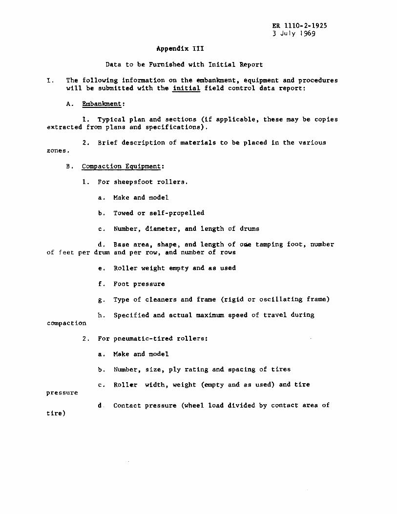
I. The following information on the embankment, equipment and procedures will be submitted with the initial field control data report:
A. Embankment:
1. Typical plan and sections (if applicable, these may be copies extracted from plans and specifications).
2. Brief description of materials to be placed in the various zones.
B. Compaction Equipment:
1. For sheepsfoot rollers.
a. Make and model
b. Towed or self-propelled
c. Number, diameter, and length of drums
d. Base area, shape, and length of ODe tamping foot, number of feet per drum and per row, and number of rows
e. Roller weight empty and as used
f. Foot pressure
g. Type of cleaners and frame (rigid or oscillating frame)
b. Specified and actual maximum speed of travel during compaction
2. For pneumatic-tired rollers:
a. Make and model
b. Number, size, ply rating and spacing of tires
c. Roller width, weight (empty and as used) and tire pressure
d. Contact pressure (wheel load divided by contact area of tire)

ER 1110-2-1925 3 July 1969 App III
e. Specified and actual maximum speed of travel during, compaction.
3. For vibratory rollers:
a. Make and model
b. Towed or self-p:ropelled
c. Number, diameter and length of drums
d. Static roller weight empty and with ballast
e. Dynamic pressure exerted
f. Vibrating frequency (report frequency of roller and rockfill within 2 feet of r~ller)
C. Summary of Test Procedures:
1. Method of correcting field and laboratory density and water content for material having plus.3/4" particle sizes.
2. Graphical presentation of compaction curves or other reference curves used for correlating field with laboratory density and water content.
3. Description of procedures for selecting appropriate laboratory maximum density and optimum water content for comparison with in-place data.
II. The following information on the instrumentation will be submitted with the initial field control data report:
A. Piezometers:
1. The type (e.g. USBR, Warlam, Hall, Casagrande, Wellpoint, etc.), tip dimensions and description of the component parts of the tip (e.g. size and type of porous stone, slot or screen size).
2. The type, wall thickness and inside diameter of pipe or tubing and method of joining sectiops.
3. The type, thickness, method of placement, gradation and top and bottom elevation of the filter surrounding the piezometer tip.
2

ER. 1110-2-1925 3 July 1969
App III
4. The type, thickness, method of placement and top and bottom elevations of the seal.
5. Type of gage and method of protection.
6. The type of surface protection, (e.g. shelter facilities, posts, etc.) date of installation, schedule of observations and problems encountered during installation and operation.
7. Plan and elevations showing location of piezometers.
B. Settlement Plates:
1. Description of settlement gage (e.g. dimensions, type, etc.) with a detailed drawing.
2. Type and size of riser pipe and method of joining sections.
3. Procedures for installation of instruments and obtaining measurements.
4. Plan and elevations showing locations of settlement plates.
C. Surface Reference Monuments:
1. Description of reference points (e.g. dimensions, type, depth of embedment, protection against damage, etc.) with a detailed drw.ving.
2. Description of bench marks.
3. Plan and elevations of reference points and bench marks.
3