distribution substations - michigan technological...
TRANSCRIPT

Distribution Substations
CHAPTER 6

Electrical Substation
An electrical substation is a subsidiary station of an electricity generation, transmission and distribution system where voltage is transformed from high to low or the reverse using transformers.
Electric power may flow through several substations between generating plant and consumer, and may be changed in voltage in several steps.
A substation that has a step-up transformer increases the voltage while decreasing the current, while a step-down transformer decreases the voltage while increasing the current for domestic and commercial distribution.

Substations generally have:1. Switching equipment2. Protection equipment3. Control equipment 4. One or more transformers
In a large substation: Circuit breakers are used to interrupt anyshort-circuits or overload currents that mayoccur on the network.
In smaller distribution stations: Recloser circuit breakers or fuses may be usedfor protection of distribution circuits.
Other devices such as capacitors and voltage regulators may also be located at asubstation.
Substations may be on the surface in fenced enclosures, underground, or located in special-purpose buildings.

Transmission substation
A transmission substation connects two or more transmission lines.
In case where all transmission lines have the same voltage: the substation contains high-voltage switches that allow lines to be connected or isolated for fault clearance or maintenance.
A transmission station may have:1. Transformers to convert between two transmission voltages, 2. Voltage control/power factor correction devices such as capacitors, reactors or
static VAR compensators 3. Phase shifting transformers to control power flow between two adjacent power
systems.
Transmission substations can range from simple to complex. The large transmission substations can cover a large area (several acres/hectares) with multiple voltage levels, many circuit breakers and a large amount of protection and control equipment.

Distribution substation
A distribution substation transfers power from the transmission system to the distribution system of an area.
The input for a distribution substation is typically at least two transmission or subtransmission lines.
Distribution voltages are typically medium voltage, between 2.4 and 33 kV depending on the size of the area served and the practices of the local utility.
Besides changing the voltage, the job of the distribution substation is to isolate faults in either the transmission or distribution systems.
Distribution substations may also be the points of voltage regulation, although on long distribution circuits (several km/miles), voltage regulation equipment may also be installed along the line.
Complicated distribution substations can be found in the downtown areas of large cities, with high-voltage switching, and switching and backup systems on the low-voltage side.

Collector substation
In distributed generation projects such as a wind farm, a collector substation may be required, which is similar to a distribution substation although power flows in the opposite direction, from many wind turbines up into the transmission grid.
For economy of construction the collector system operates around 35 kV, and the collector substation steps up voltage to a transmission voltage for the grid.
The collector substation can also provide power factor correction if it is needed, metering and control of the wind farm.
Collector substations also exist where multiple thermal or hydroelectric power plants of comparable output power are in proximity.

Switching substation
A switching substation is a substation which does not contain transformers and operates only at a single voltage level.
Switching substations are sometimes used as collector and distribution stations.
Sometimes they are used for switching the current to back-up lines or for paralellizing circuits in case of failure.

Design
The main considerations taking into account during the design process are:
1. Reliability
2. Cost (sufficient reliability without excessive cost)
3. Expansion of the station, if required.
Selection of the location of a substation must consider many factors:
1. Sufficient land area
2. Necessary clearances for electrical safety
3. Access to maintain large apparatus such as transformers.
4. The site must have room for expansion due to load growth or planned
transmission additions.
5. Environmental effects( drainage, noise and road traffic effects.
6. Grounding must be taking into account to protect passers-by during a short-
circuit in the transmission system
7. The substation site must be reasonably central to the distribution area to be
served.

Layout
The first step in planning a substation layout is the
preparation of a one-line diagram which shows in
simplified form the switching and protection
arrangement required, as well as the incoming
supply lines and outgoing feeders or transmission
lines.
One-line diagram should include principal elements:
Lines
Switches
Circuit breakers
Transformers
Incoming lines should have a disconnect switch and a circuit breaker.
A disconnect switch is used to provide isolation, since it cannot interrupt load
current.
A circuit breaker is used as a protection device to interrupt fault currents
automatically.
Both switches and circuit breakers may be operated locally or remotely from a
supervisory control center.

Layout
Following the switching components, the lines are connected to one or more
buses.
An electrical bus, derived from bus bar, is a common electrical connection
between multiple electrical devices.
Symbolic representation of a bus: The thick line is the bus, which represents
three wires. The slash through the bus arrow and the "3" means that the bus
represents 3 wires
The arrangement of switches, circuit breakers and buses used affects the cost
and reliability of the substation.
For important substations a ring bus or double bus.
Substations feeding only a single industrial load may have minimal switching
provisions.
Once having established buses for the various voltage levels, transformers may
be connected between the voltage levels. These will again have a circuit
breaker in case a transformer has a fault.
A substation always has control circuitry to operate the various breakers to
open in case of the failure of some component.
Layout

Switching function
Switching is the operation of connecting and disconnecting of transmission
lines or other components to and from the system.
Switching events may be "planned" or "unplanned".
A transmission line or other component may need to be deenergized for
maintenance or for new construction.
To maintain reliability of supply, it is not cost efficient to shut down the entire
power system for maintenance.
All work to be performed, from routine testing to adding entirely new
substations, must be done while keeping the whole system running.
Also, a fault may develop in a transmission line or any other component. The
function of the substation is to isolate the faulted portion of the system in the
shortest possible time.

Load
The size of the load to be served determines the capacity of the substation.
The load must be distributed such that it can be served with reasonable feeder
loss or more.
Critical loads (industrial districts) are served by more complex substations,
designed for maximum reliability and speed of power restoration compare to the
ones used in residential areas where a short time power loss is usually not a disaster.
Other substations in the area influence the design of a new substation.
The presence of the other substations will increase the overall power capacity and
as a result can satisfy the demand for heavy loads.

Substations for critical loads usually use more than one transformer so that the
load is served even if one transformer is out.
Otherwise a single large three-phase transformer is used because it costs less
per kVA of capacity, and requires less room, bussing, and simpler protective
relaying.

Distribution Substation Protection Needs
Above a minimum protection needed to avoid injury to people and damage to equipment,
the level of protection of a substation is determined by how critical the loss of power is to the
load.
The loss of electrical power to a hospital is very serious while the loss of power to a residence
is inconvenient. In the event of a fault the hospital electricity must be restored in the shortest
amount of time possible while the residence can be without electricity several hours without serious
consequences.
Equipping a substation with automatic
switching to restore power when it is lost
and to assure the least possible damage
and repair time after a fault is expensive.
A small substation at the end of a radial subtransmission line that might be used to serve a small group of
residences. It consists of two dead end poles to terminate the lines, two manual non-load break switches,
and primary fusing.
Distribution Substation Protection Needs
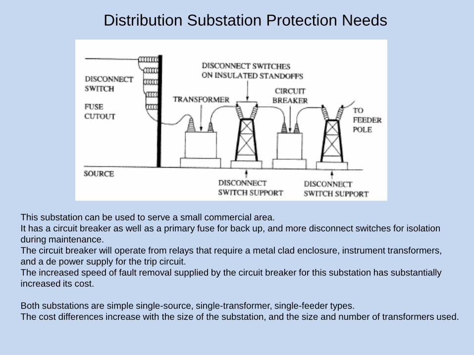
This substation can be used to serve a small commercial area.
It has a circuit breaker as well as a primary fuse for back up, and more disconnect switches for isolation
during maintenance.
The circuit breaker will operate from relays that require a metal clad enclosure, instrument transformers,
and a de power supply for the trip circuit.
The increased speed of fault removal supplied by the circuit breaker for this substation has substantially
increased its cost.
Both substations are simple single-source, single-transformer, single-feeder types.
The cost differences increase with the size of the substation, and the size and number of transformers used.

DISTRIBUTION SUBSTATION CONSTRUCTION METHODS
Four basic methods exist for substation construction:
1. Wood
2. Steel lattice
3. Steel low profile
4. Unit.
Wood pole substations are inexpensive, and can easily use wire bus structures. Wood is suitable
only for relatively small, simple substations because of the difficulty of building complex bus and
switch gear support structures from wood.
Lattice steel provides structures of low weight and high strength. Complex, lattice steel is
reasonably economical and is the preferred material for substation construction whenever
possible.
Solid steel low profile substations are superior to lattice or wood constructed substations.
However, low profile construction is more expensive than either wood or lattice steel, and requires
more land because multilevel bus structures cannot be used.
The unit substation is a relatively recent development. A unit substation is factory built and tested,
then shipped in modules that are bolted together at the site.
Unit substations usually contain high and low voltage disconnect switches, one or two three-phase
transformers, low voltage breakers, high voltage fusing, bus work, and relays.

DISTRIBUTION SUBSTATION LAYOUT
1. Single source, single feeder substation
The one-line diagram of a single-source, single-feeder
substation with the minimum equipment used.
A bypass switch is provided so service can continue during
circuit breaker maintenance.
The probability of a fault during circuit breaker maintenance
is small, but still there as a result the transformer is protected
by a primary fuse to back up the breaker, and provide
some protection for internal transformer faults.
The minimum relaying is overcurrent on the secondary side
of the transformer.
The switches can be manually or motor operated.

2. Single bus substation
This is the one line of a single bus substation
fed by a single radial subtransaission line.
Each feeder must has its own overcurrent
protection.
The primary switch must be able to break the
transformer excitation current.
The transformer may have differential relaying
that trips all of the feeder breakers in the event of
a fault.
Each distribution voltage the substation supplies
must have its own bus.
The possibility of a subtransmission circuit fault is
much higher than a transformer fault. Two sources
allow service to be restored more quickly upon a
subtransmission circuit fault.

2. Single bus substation
This is the one line of a double throw switch on the primary side which allows the transfer to be
made quickly from one subtransmission circuit to another.
The switch is interlocked with the transformer breaker so it cannot be opened under load.
The switch can be replaced by two manual high voltage breakers that can break the load, and
expected fault current.
The transformer secondary breaker makes possible very effective differential bus protection to
detect faults internal to the bus. The bus relays then trip all of the circuit breakers connected to the
bus upon a bus fault.

3. Two Transformer Distribution Substations
More critical loads implement a two transformer distribution
substation allowing to significantly decrease the out of service time.
Normally the transformers are rated at 75% capacity when self
cooled and equipped with automatic air cooling that is used when
one transformer must handle the entire substation capacity.
The tie switch between the two transformer connections to the bus
which is in open state when both transformers are in use to prevent
the transformer secondaries from operating in parallel.
Momentary parallel operation during switching is often permissible
but must be avoided for the extended operation time due to the high
secondary currents.
The primary side switching is arranged so that either or both
transformers can be fed by either subtransmission line.
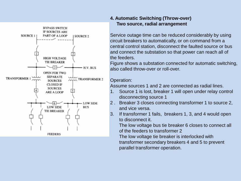
4. Automatic Switching (Throw-over)
Two source, radial arrangement
Service outage time can be reduced considerably by using
circuit breakers to automatically, or on command from a
central control station, disconnect the faulted source or bus
and connect the substation so that power can reach all of
the feeders.
Figure shows a substation connected for automatic switching,
also called throw-over or roll-over.
Operation:
Assume sources 1 and 2 are connected as radial lines.
1. Source 1 is lost, breaker 1 will open under relay control
disconnecting source 1
2 . Breaker 3 closes connecting transformer 1 to source 2,
and vice versa.
3. If transformer 1 fails, breakers 1, 3, and 4 would open
to disconnect it.
The low voltage bus tie breaker 6 closes to connect all
of the feeders to transformer 2
The low voltage tie breaker is interlocked with
transformer secondary breakers 4 and 5 to prevent
parallel transformer operation.

4. Automatic Switching (Throw-over)
Loop Arrangement
A preferred automatic switching scheme for loop
connected supply lines is shown.
Circuit breakers A and B remove a faulted line from
service, while circuit breakers C and C’ and D and D’
remove the transformers in the event they fault.
Upon a transformer failure the low voltage tie breaker
connects all of the working feeders to whichever
transformer is working.

Bus Arrangements
The ring bus requires only one circuit breaker per line so it is
economical.
Power can reach any feeder from two directions so no feeder
need be disconnected when one breaker is down for service.
Two breakers are operated when a feeder fault occurs, one on
either side of the feeder.
If a second breaker trips when one feeder is down the entire
bus may be disconnected from a source.
The ring bus is therefore seldom used if the feeders exceed
the source lines by than a factor of two.
The breaker an a half is a reasonably economical, versatile,
Reliable and as a result is very popular.
A bus or feeder fault can easily be isolated while the station
remains in service.
The breaker and a half is usually used in substations with
more than four feeders.

TRANSMISSION LINE FAULT CALCULATIONS
Fault Classifications :
1. Line to ground. Line to ground faults are caused by a line touching the ground. Wind, ice loading, tree falling on a line can cause a line to ground fault. This category accounts for about 70% of all line short circuit faults.
A system fault is defined as any abnormal condition.
25

Fault Classifications :
2. Line to line. These faults are caused by high winds blowing one line into another, or by a line breaking and falling on a line below it.These account for about 15% of line faults.
26

Fault Classifications :
3. Double line to ground. This category is caused by the same things that cause single line to ground faults, except two lines are involved instead of one. These account for about 10% of line faults.
27

Fault Classifications :
4. Three-phase faults. If a line condition occurs in which all three phases are shorted together, an equipment failure, or all three lines falling to the ground, it is called a three-phase fault. Accounts for only about 5% of all line faults.
28

The point at which a conductor touches ground or another conductor during a fault is usually accompanied by an arc.
The arc is resistive, but arc resistance varies widely.
The usual utility practice is to consider the fault resistance zero to calculate the maximum fault current that can occur at a point of interest on a line.
The fault current that flows depends on the source, line, and fault impedances:
29

DISTRIBUTION SUBSTATION PROTECTION
Circuit breakers tripped by protective relays are used to protect the
equipment within a substation, with primary fusing used to protect the
transformers in some smaller substations.
Each relay set and circuit breaker is set to protect a certain portion of
the substation and restrict the amount of the substation removed from
service for a given fault.
The portion of the substation removed from service by a given relay
set is its zone of protection
Each protective element normally has a backup in this manner to
provide protection if the first line protection fails to operate.

Transformer Protection
Transformers are very expensive, and
so are well protected.
A substation transformer has a
minimum of:
1. Secondary overcurrent relaying
2. Primary fusing
3. Sudden pressure relay.
The sudden pressure relay (SPR) is a
relay, attached to a valve on the
transformer that will detect the sudden
rise in pressure caused by internal arcing
and trip the secondary breaker.
The SPR will not respond to the gradual
rise in pressure caused by an increase in
loading.
Except for very small substations
transformers also have differential
relaying with back-up overcurrent
relaying.

Transformer Protection
Figure shows a one-line drawing of a well-protected
transformer.
The back-up primary overcurrent protection can use
separate CTs than the differential relays.
A number of different ground fault protection possibilities
are shown in the figure.
The 50N/5IN in the primary overcurrent relaying.
A good place to detect a ground fault in a grounded Y
system is on the neutral to ground conductor.
No current should flow in this conductor unless a ground
fault exists.
Resistors are used in the ground conductor to limit the
transient voltage from line capacitance charging on long
subtransmission and transmission lines, and to limit
current in the event of a fault from a phase to ground.

Bus Protection
Differential protection is effective for bus faults because the current leaving the bus on
feeders and the current entering the bus from sources should be zero at any instant.
Additionally, differential protection can distinguish between internal bus faults and external
feeder faults. A feeder fault can result in the CTs on the feeder saturating, and the dc offset
of a fault worsens the situation. Thus special care must be taken in bus differential relaying
to prevent external faults from causing a trip on the circuit breakers supplying the bus.
Three major systems are used: .
1. Linear coupler (LC) system, which works by eliminating the iron core of the CTs.
2. Multi-restraint, variable percentage relays (CA-16).
3. High impedance voltage operated differential relays (KAB).

Linear coupler systems use air core transformers
that do not saturate.
The LC system is fast, less than 16 ms for LC-l
and 32 ms for LC-2 relays.
The LCs are actually designed to provide 5 V
secondary voltage, detected by the relay, for
every 1000 A primary current.
The LC connection for a very small bus is shown.
The LCs are connected in series.
In normal operation or during an external fault the
sum of the LCs voltages is zero because the LC
voltages are proportional to the line current and
the source and feeder currents sum to zero.
During a bus fault at least one of the feeder
currents approaches zero and its LC voltage
drops. The voltage sum of the LCs is no longer
zero and the relay operates.
Air-core transformers
These are used for high frequency work. The lack
of a core means very low inductance. Such
transformers may be nothing more than a
few turns of wire.

Multi-restraint differential schemes use conventional CTs, which saturate on heavy external faults. In a
differential scheme, the current transformers and relay function as a team. When the current transformers do
not perform adequately, the relay can within limits make up for the deficiency.
The multirestraint differential scheme uses the CA- 16 variable-percentage differential relay, which consists of
three induction restraint units and one induction operating unit per phase. Two of the units are placed opposite
each other and operate on a common disc. In turn, the two discs are connected to a common shaft with the
moving contacts.
All four of the units are unidirectional; that is, current flows in either direction through the windings generates
contact-opening torque for the restraint units or contact- closing torque for the operating unit.
Each restraint unit (R, S, and T) also has two windings to provide restraint proportional to the sum or difference,
depending on the direction of the current flow. If the currents in the two paired windings are equal and opposite,
the restraint is cancelled. Thus, the paired restraint windings have a polarity with respect to each other. With
this method six restraint windings are available per phase.

The KAB is a high impedance differential relay
The high impedance differential KAB relay consists of an
instantaneous overvoltage cylinder unit (V), a voltage-
limiting suppressor (varister), an adjustable tuned circuit,
and an instantaneous current unit (IT).
On external faults, the voltage across the relay terminals
will be low, essentially 0, unless the CTs are unequally
saturated.
On internal faults, the voltage across the relay terminals
will be high and will operate the overvoltage unit.
The varistor limits the voltage to a safe level.
Since offset fault current or residual magnetism exists in
the CT core, there is an appreciable dc component in the
secondary current. The dc voltage that appears across
the relay will be filtered out by the tuned circuit, preventing
relay pickup.
The IT current unit provides faster operation on severe
internal faults and also backup to the voltage unit.
The KAB relay has successfully performed operations up
to external fault currents of 200 A secondary and typical
operating speed is 25 msec.

SUBSTATION GROUNDING
Substation grounding is done safety, and to provide a stable reference voltage for protection systems.
The grounding system of a substation consists of a ground mat made of large size bare conductors,
connected in a grid pattern, and buried beneath the substation.
The perimeter of the grid is connected to metal rods driven about 30 feet into the ground. The grid wires
are about 20 feet apart but the spacing varies with the conductivity of the soil.
Highly conductive soil can use larger grid wire spacing.
All substation structures are to be constructed within the perimeter of the grid.
The fence around a substation has two buried ground wires connected to the fence every few feet.
One runs about 3 feet outside the fence, and one inside the fence.
Both wires are connected to grounding rods every 50 feet.

Sources:
1. “Electrical Power Distribution and Transmission”, L.M Faulkenberry and W. Coffer.
2. http://en.wikipedia.org/wiki/Electrical_substation
3. http://www.scribd.com/doc/6767188/Station-Bus-Protection