disturbance observer and optimal fuzzy controllers...
TRANSCRIPT

The International Journal Of Engineering And Science (IJES)
|| Volume || 3 || Issue || 8 || Pages || 44-63 || 2014 ||
ISSN (e): 2319 – 1813 ISSN (p): 2319 – 1805
www.theijes.com The IJES Page 44
“Disturbance Observer And Optimal Fuzzy Controllers Used In
Controlling Force And Torque In High Performance Drilling
Process To Minimize The Cutting Time For Ferrous And Non-
Ferrous Industrial Materials”
1Singh Rajendra (Assoc. Prof.)
2 Tiwari Ashuttosh Kr. (A.P)
3Singh Deepak Kr.
(A.P) 1,2,3
Aryan Institute Of Technology, Jindal Nagar, GHAZIABAD(UP), INDIA
------------------------------------------------------------ABSTRACT-----------------------------------------------------------
The automation of machining processes requires highly accurate process monitoring. However, the use of
additional sensors leads to a significant increase in the cost and reduces the stiffness and reliability of
mechanical systems. Hence, we propose a system called the cutting force and torque observer, which uses a
sensor-less and real-time cutting force estimation methodology based on the disturbance observer theory.
Monitoring methods using the cutting force and torque observer may enhance the productivity during drilling
process in which one of the parameters that significantly affect the cutting process is the shear angle. The
determination of the shear angle is very important as it can be used for identifying the machining conditions. In
this study, an external sensor-less monitoring system of the shear angle during turning is developed, and its
performance is evaluated. This paper deals with Proportional-Integral-Derivative (PID) controller and optimal
fuzzy logic used in a high performance drilling system for controlling the output obtained. The main objective is
to obtain a stable, robust and controlled system by tuning, PID controller and fuzzy-control logic using
minimization of the incurred value is compared with the traditional tuning techniques is improved better. Hence
that drilling process results estimates the tuning in which PID controller using minimization technique gives
less overshoot and better control performance with many advantages such as flexibility, and reduced
maintenance time and cost. This 49-rule controller is networked and operates on a CNC machine tool. It is
optimally tuned using a known maximum allowable delay to deal with uncertainties in the drilling process and
delays in the network-based application.
KEY WORDS: Cutting force and torque, monitoring high-performance drilling process, shear angle,
disturbance observer and optimal Fuzzy controllers.
---------------------------------------------------------------------------------------------------------------------------------------
Date of Submission: 20 July 2014 Date of Publication: 30 August 2014
---------------------------------------------------------------------------------------------------------------------------------------
I. INTRODUCTION
The cutting force is the most basic process information required for monitoring a machining process.
The cutting force is monitored for detecting tool wear, tool breakage, and chatter vibration, which lead to low
productivity. Generally, for monitoring the cutting force, additional sensors such as dynamometers are used. In
order to achieve the transparency, and feel the sensation from the remote site, teleoperation architectures need
properly measured force information. Up to date, however, many teleoperation systems have been using force
sensors for haptic(force) feedback and control. To overcome the drawbacks of the force sensors, proposed works
in this research work estimate the disturbance torque by using an input and an output signal of the motor
installed on the each joint of the manipulator. As a result of the estimation, the estimated disturbance torque
information, the angular position and the angular velocity of each joint will be transmitted to the opposite side
without any force sensors. Thus, control designers will be able to apply many teleoperation architectures and
their own control strategies with the force feedback.Recent rapid technological progress in machine tool
performance is largely attributable to developments in feed drive and spindle motion control and machine and
coolant temperature control. Advances in numerically controlled machine tools have made it necessary to expert
machine operators and parts-programmers to determine machining and operating parameters such as the
selection of tools, feed rates, spindle speed, and depths of cut. In conventional numerically-controlled machining
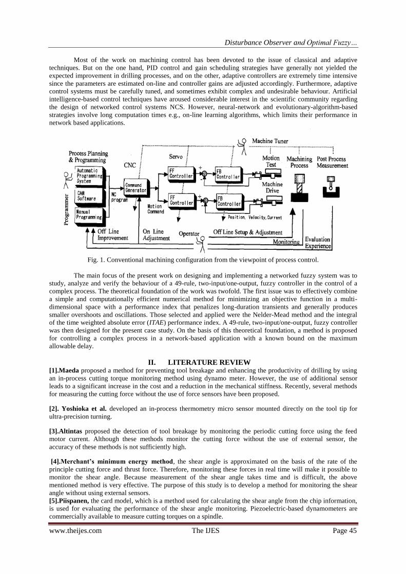
seen from process control, as shown in Fig. 1, operators conduct process planning and programming using
computer-aided manufacturing CAM software or an automatic programming system installed on CNC.
Disturbance Observer and Optimal Fuzzy…
www.theijes.com The IJES Page 45
Most of the work on machining control has been devoted to the issue of classical and adaptive
techniques. But on the one hand, PID control and gain scheduling strategies have generally not yielded the
expected improvement in drilling processes, and on the other, adaptive controllers are extremely time intensive
since the parameters are estimated on-line and controller gains are adjusted accordingly. Furthermore, adaptive
control systems must be carefully tuned, and sometimes exhibit complex and undesirable behaviour. Artificial
intelligence-based control techniques have aroused considerable interest in the scientific community regarding
the design of networked control systems NCS. However, neural-network and evolutionary-algorithm-based
strategies involve long computation times e.g., on-line learning algorithms, which limits their performance in
network based applications.
Fig. 1. Conventional machining configuration from the viewpoint of process control.
The main focus of the present work on designing and implementing a networked fuzzy system was to
study, analyze and verify the behaviour of a 49-rule, two-input/one-output, fuzzy controller in the control of a
complex process. The theoretical foundation of the work was twofold. The first issue was to effectively combine
a simple and computationally efficient numerical method for minimizing an objective function in a multi-
dimensional space with a performance index that penalizes long-duration transients and generally produces
smaller overshoots and oscillations. Those selected and applied were the Nelder-Mead method and the integral
of the time weighted absolute error (ITAE) performance index. A 49-rule, two-input/one-output, fuzzy controller
was then designed for the present case study. On the basis of this theoretical foundation, a method is proposed
for controlling a complex process in a network-based application with a known bound on the maximum
allowable delay.
II. LITERATURE REVIEW [1].Maeda proposed a method for preventing tool breakage and enhancing the productivity of drilling by using
an in-process cutting torque monitoring method using dynamo meter. However, the use of additional sensor
leads to a significant increase in the cost and a reduction in the mechanical stiffness. Recently, several methods
for measuring the cutting force without the use of force sensors have been proposed.
[2]. Yoshioka et al. developed an in-process thermometry micro sensor mounted directly on the tool tip for
ultra-precision turning.
[3].Altintas proposed the detection of tool breakage by monitoring the periodic cutting force using the feed
motor current. Although these methods monitor the cutting force without the use of external sensor, the
accuracy of these methods is not sufficiently high.
[4].Merchant’s minimum energy method, the shear angle is approximated on the basis of the rate of the
principle cutting force and thrust force. Therefore, monitoring these forces in real time will make it possible to
monitor the shear angle. Because measurement of the shear angle takes time and is difficult, the above
mentioned method is very effective. The purpose of this study is to develop a method for monitoring the shear
angle without using external sensors.
[5].Piispanen, the card model, which is a method used for calculating the shear angle from the chip information,
is used for evaluating the performance of the shear angle monitoring. Piezoelectric-based dynamometers are
commercially available to measure cutting torques on a spindle.
Disturbance Observer and Optimal Fuzzy…
www.theijes.com The IJES Page 46
[6].Ohzeki et al. studied the use of magneto strictive torque sensors in the spindle. A potentially critical issue
with sensors integrated in spindles is the heat generated by the spindle motor.
[7].Jun et al. studied this, suggesting that temperature compensation was needed to reliably monitor torque. A
torque or force sensor within the spindle may be difficult to install on many machines due to space restrictions.
Alternatively, sensors are integrated into a tool holder, as is already commercially available.
[8].Artis, integrated strain gauges into a tool holder to measure torque, axial, and radial forces.
[9]. Montronix, commercialized small sensor-integrated plates or rings installed at different places on the
machine, including the spindle head, affected by cutting force.
[10]. Kim et al. developed a cylindrical capacitance sensor installed near front spindle bearings to measure gap
variation between the sensor head and the rotating spindle shaft under cutting load.
[11]. Albrecht et al. used a capacitance sensor to calculate cutting force, showing that bandwidth up to 1,000
Hz was obtained when spindle dynamics was compensated.
[12].Jeong et, all measured spindle displacement in turning using three capacitance displacement sensors
similarly. The gap in a spindle supported by active magnetic bearings is calculated from command voltage to
magnetic bearings , analogous to a capacitance sensor, and can be used to calculate cutting force . A high-speed
spindle with sensors integrated to monitor spindle conditions such as vibration, run-out, and temperature, is
gaining wider use in high-speed commercial machines .
[13].Altintas and Lee et al. discussed tool breakage detection based on cutting force calculation by servo motor
current. A similar attempt was made observing spindle motor armature current. In many commercial CNCs,
spindle load is displayed on a screen, seen as the simplest form of cutting torque calculation. Some CNCs
digitally output calculated disturbance from servo motor currents.
[14].Liang et al. and Altintas, among in-process machining parameters, feed rate is the easiest to manage. Most
commercial CNCs have dials for manually changing feed rate override, while some enable users to input a
signal to continuously regulate it. Cutting force control is reviewed in the sections that follow, using feed rate as
a control variable. Part of our reviews is included in machining control discussed.
[15].Landers et al. many approaches explicitly model the cutting force through geometric and process
variables, e.g. spindle speed, feed rate, depth of cut, etc as described in the overview. [16].Kim et al. for the
drilling process in particular, analyzed the thrust force (F) and feed rate (f) of the drilling operation on a CNC
machine tool, creating a linear, first-order system, where the system gain and time constant are dependent on
machining conditions and the material's properties.
III. THEORETICAL BACK GROUND Drilling covers the methods of making cylindrical holes in a work piece with metal cutting tools.
Drilling is associated with subsequent machining operations such as trepanning, counter boring, reaming and
boring. Common to all these processes is a main rotating movement combined with a linear feed. There is a
clear distinction between short hole and deep hole drilling, the latter being a specialist method for making holes
that have depths of many times up to 150 times the diameter With the development of modern tools for short
hole drilling, the need for preparatory and subsequent machining has changed drastically. Modern tools have led
to solid drilling being carried out in a single operation, normally without any previous machining of centre and
pilot holes. The hole quality is good, where subsequent machining to improve the measurement accuracy and
surface texture is often unnecessary.
Disturbance Observer and Optimal Fuzzy…
www.theijes.com The IJES Page 47
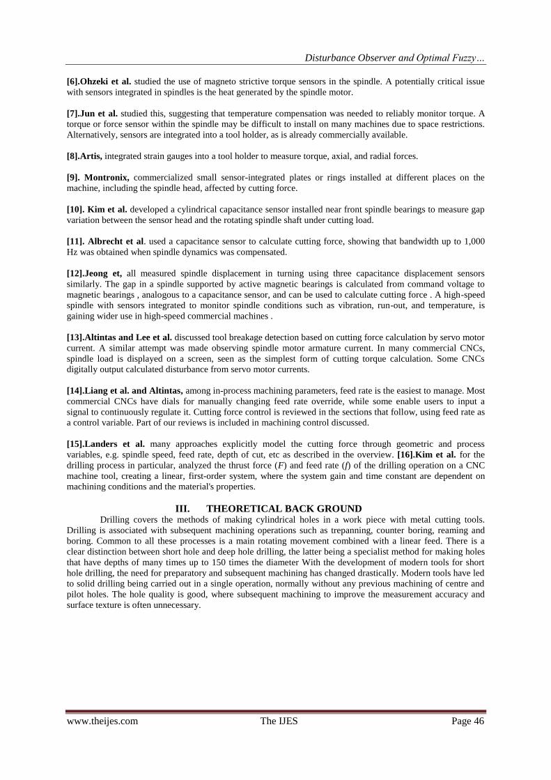
Figure 2: Drilling process during holes in work materials
MONITORING OF CUTTING FORCES AND TORQUES :Tool breakage is costly both in time lost and
materials destroyed. Tool failure is estimated to account for 20% of the downtime of an average modern
machine tool. Tool breakage and severe tool wear may be avoided by using conservative machining conditions,
which sacrifices machining efficiency. Many parts machining experts tend to choose heavy-cut machining rather
than high-speed machining, which may require more frequent tool changes and higher tool cost. Accurate,
reliable tool condition monitoring (TCM) could cut machining time by 10-50%, downtime reduction by
scheduling it in advance, which has led to the active study of in-situ tool wear and breakage detection. This
section reviews cutting force and torque monitoring.
Force Sensors : We collectively call sensors installed on machine tools to monitor cutting force “external”
sensors . This is contrast to “internal” sensors – current sensors for servo and spindle motors installed on NC
machine tools. Commercially available dynamometers measure cutting force using quartz piezoelectric
transducers. Table and spindle dynamometers are commercially available. These dynamometers have sufficient
resolution to be used in micro machining using a non rotating tool or a miniature rotating tool up to several
dozen microns in the diameter. Despite the accuracy and reliability of commercial dynamometers, their high
cost may limit their use in machining process control.
Torque Sensors : Piezoelectric-based dynamometers are commercially available to measure cutting torques on
a spindle. Cutting torque was also calculated using strain gauges . Ohzeki et al. studied the use of magneto
strictive torque sensors in the spindle. A potentially critical issue with sensors integrated in spindles is the heat
generated by the spindle motor. Jun et al. studied this, suggesting that temperature compensation was needed to
reliably monitor torque. A torque or force sensor within the spindle may be difficult to install on many machines
due to space restrictions. Alternatively, sensors are integrated into a tool holder, as is already commercially
available. Artis integrated strain gauges into a tool holder to measure torque, axial and radial forces.
Cutting Force Calculation by Spindle Displacement : Assessing force or torque using a sensor on a machine
spindle may require a highly complex arrangement to ensure required resolution throughout the entire machine
tool power range, and the measurement signal must be transmitted without contact from the rotating spindle.
Non-contact measurement of displacement is easier than measuring force or torque. Calculating cutting force
from spindle displacement has been also studied. One example is the cutting force calculation that we developed
using spindle-integrated displacement sensors, shown in Fig. 2. We used four inexpensive, contamination-
resistant eddy-current displacement sensors (S1-S4). Calculating cutting force from spindle displacement,
however, involves two major issues – thermal influence and spindle stiffness. Motor heat may critically deform
or displace a rotating spindle, which must be separated from displacement caused by cutting force. In many
commercial machining centers, the spindle is thermally controlled by circulating coolant through cooling
jackets. In on-off temperature control, thermal deformation, is significantly influenced by its control period. In
our study, multiple thermocouples are installed in the spindle to calculate thermal displacement. Many studies
have reported thermal-mechanical spindle modeling. In addition to thermal influence, another critical issue is
spindle stiffness, involving the entire spindle system, including a tool holder, a collet, and a tool.

Disturbance Observer and Optimal Fuzzy…
www.theijes.com The IJES Page 48
Figure: 2. Spindle-integrated displacement sensor configuration for determining cutting force.
Cutting Force Monitoring by Internal Sensors :Commercial numerically-controlled machine tools having
servo motors in a feed drive or spindle motors have current sensors for motion control. When torque induces
motor disturbance, armature current is modified by the servo controller to cancel its influence, so cutting torque
or force is calculated from a motor’s armature current – probably the cheapest way to monitor cutting loads
because no extra sensors are needed. Commercial products to monitor spindle or servo motor current provide
fault detection. Armature current is influenced by dynamic characteristics of the drive system. In a feed drive,
particularly, compensating for the dynamics of the moving mass is important in separating out the influence of
cutting force. A disturbance observer for a feed drive can be applied for this purpose. Algorithms to analyze and
detect abnormal machining process, such as tool breakage, have been drawing attention in academia for years. A
frequency domain analysis, statistic analysis, an artificial neural network , wavelet analysis and complexity
analysis were applied in fault detection. We studied practical issues calculating cutting force using motor current
on a small commercial machining center. Fig. 3 shows the armature current of a servo motor when the single
linear axis is driven under a constant feed rate of 1,000 mm/min without a cutting load (ar-mature current is
converted to drive force by torque coefficient and ball screw lead). Fig. 3 compares two feed drives – one driven
by a rotary servo motor and a ball screw with roller bearings, and the other driven by a linear motor with
hydrostatic guide ways. On a feed drive driven by a servo motor and roller or slide guide ways, commonly used
in most commercial machining centers, the servo motor undergoes large friction imposed on guide ways or a
ball screw. As shown in Fig. 3, the motor in the ball screw drive gives the driving force as 1000 N even with no
cutting load to overcome friction.
Fig. 3. Feed drive force during Y-axis movement at a constant non-cutting feed rate.
Disturbance Observer and Optimal Fuzzy…
www.theijes.com The IJES Page 49
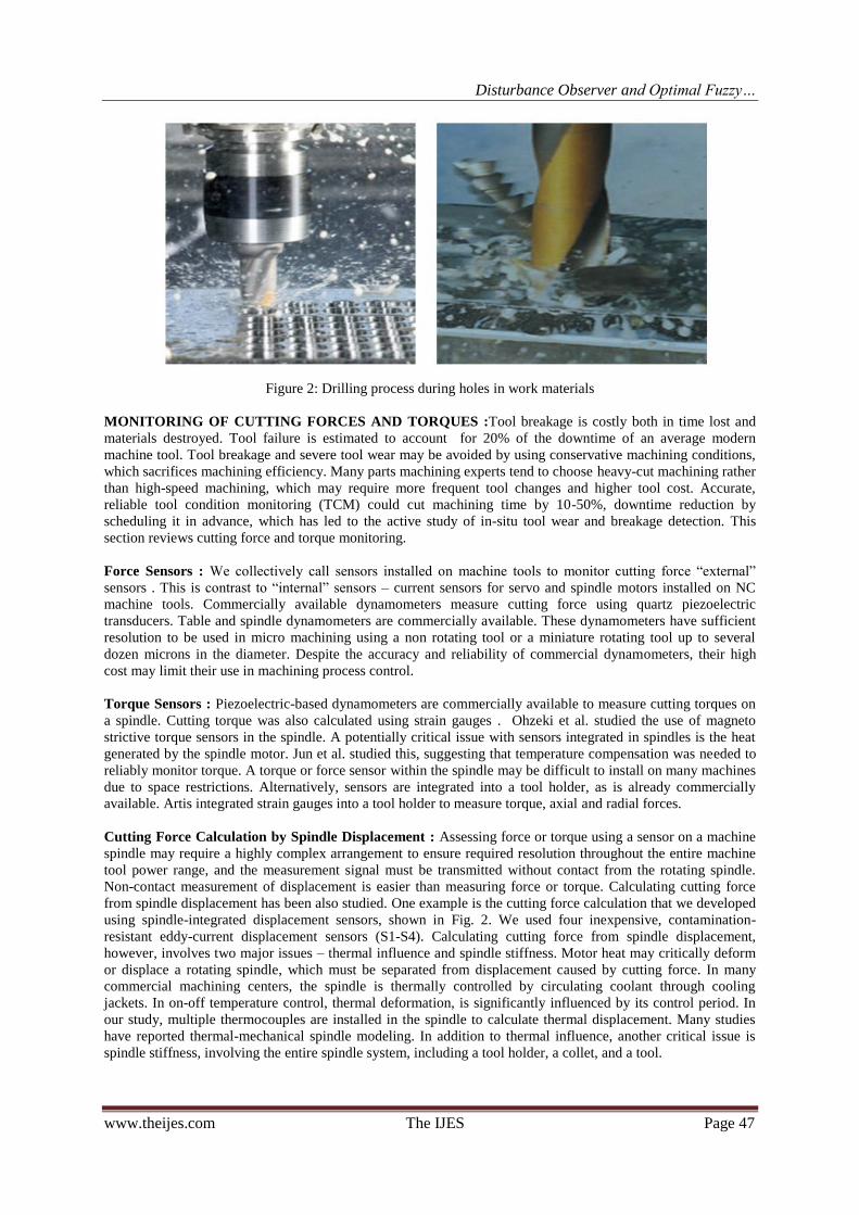
Fig. 4. Comparison of cutting force (horizontal axis) and estimates by monitoring servo motor current (vertical
axis) under straight end mill side cutting.
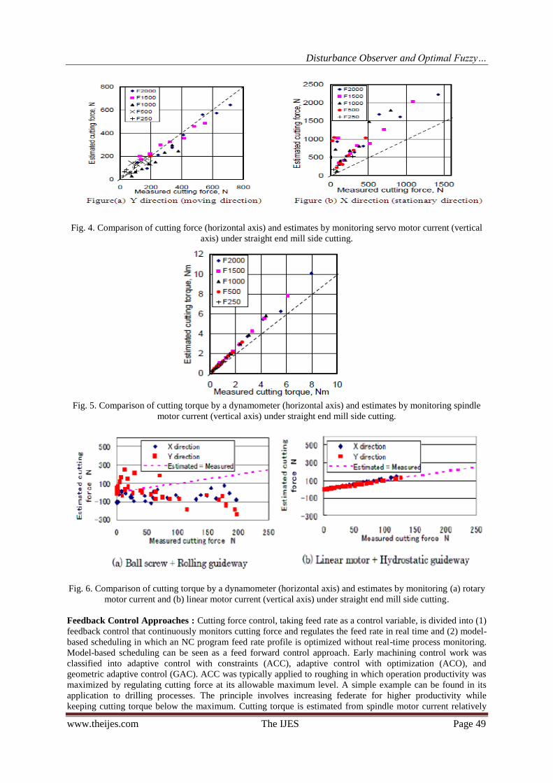
Fig. 5. Comparison of cutting torque by a dynamometer (horizontal axis) and estimates by monitoring spindle
motor current (vertical axis) under straight end mill side cutting.
Fig. 6. Comparison of cutting torque by a dynamometer (horizontal axis) and estimates by monitoring (a) rotary
motor current and (b) linear motor current (vertical axis) under straight end mill side cutting.
Feedback Control Approaches : Cutting force control, taking feed rate as a control variable, is divided into (1)
feedback control that continuously monitors cutting force and regulates the feed rate in real time and (2) model-
based scheduling in which an NC program feed rate profile is optimized without real-time process monitoring.
Model-based scheduling can be seen as a feed forward control approach. Early machining control work was
classified into adaptive control with constraints (ACC), adaptive control with optimization (ACO), and
geometric adaptive control (GAC). ACC was typically applied to roughing in which operation productivity was
maximized by regulating cutting force at its allowable maximum level. A simple example can be found in its
application to drilling processes. The principle involves increasing federate for higher productivity while
keeping cutting torque below the maximum. Cutting torque is estimated from spindle motor current relatively
Disturbance Observer and Optimal Fuzzy…
www.theijes.com The IJES Page 50
accurately. Thrust force estimated from servo motor current is also reliable, unlike cutting force in drilling
machine. These were extended to tapping with adaptive “pecking” and were implemented in commercial CNC.
Other cutting force and torque control applications have been made to drilling processes implemented in
industry.
III. PID CONTROLLER FOR A HIGH PERFORMANCE DRILLING MACHINE In the control system, unknown disturbance detrimentally influences on not only stability but also
performance. However, not all state variables and disturbance are available for feedback, i.e., some of them are
not measurable. Thus, we need to estimate unmeasurable state variables and disturbance for disturbance
compensation.
State observers : A device or program that estimates or observes state variables of a system is called a state
observer. A state observer utilizes measurements of the system inputs, outputs and a model of the system based
on differential equations. In order to estimate unmeasurable state variables, many kinds of observer have been
researched. In this subsection some of observers are introduced.
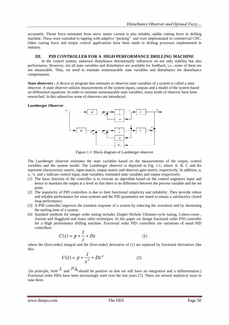
Luenberger Observer
Figure 1.1: Block diagram of Luenberger observer
The Luenberger observer estimates the state variables based on the measurements of the output, control
variables and the system model. The Luenberger observer is depicted in Fig. 1.1, where A, B, C and Ke
represent characteristic matrix, input matrix, output matrix and observer gain matrix, respectively. In addition, u,
x, ^x and y indicate control input, state variables, estimated state variables and output respectively.
[1] The basic function of the controller is to execute an algorithm based on the control engineers input and
hence to maintain the output at a level so that there is no difference between the process variable and the set
point.
[2] The popularity of PID controllers is due to their functional simplicity and reliability .They provide robust
and reliable performance for most systems and the PID parameters are tuned to ensure a satisfactory closed
loop performance.
[3] A PID controller improves the transient response of a system by reducing the overshoot and by shortening
the settling time of a system.
[4] Standard methods for integer order tuning includes Ziegler-Nichols Ultimate-cycle tuning, Cohen-coons ,
Astrom and Hagglund and many other techniques. In this paper we design fractional order PID controller
for a High performance drilling machine. Fractional order PID controllers are variations of usual PID
controllers:
where the (first-order) integral and the (first-order) derivative of (1) are replaced by fractional derivatives like
this:
(In principle, both and should be positive so that we still have an integration and a differentiation.)
Fractional order PIDs have been increasingly used over the last years [7]. There are several analytical ways to
tune them.

Disturbance Observer and Optimal Fuzzy…
www.theijes.com The IJES Page 51
Dynamic model of a high-performance drilling process : The modeling of a high-performance drilling
process includes the modeling of the feed drive system, the spindle system and the cutting process. In this paper,
the overall plant model is obtained by experimental identification using different step shaped disturbances in the
command feed. The drilling force, F, is proportional to the machining feed, and the corresponding gain varies
according to the work piece and drill diameter. The overall system of the feed drive, cutting process and
dynamometric platform was modeled as a third-order system, and the experimental identification procedure
yielded the transfer function as:
where s is the Laplace operator. The model does have certain limits in representing the complexity and
uncertainty of the drilling process. However, it provides a rough description of the process behavior that is
essential for designing a network- based PID control system.
A brief introduction to fractional order calculus A commonly used definition of the fractional differo-integral is the Riemann-Liouville definition
For , where, is the well-known Euler,s gamma function. An alternative definition,
based on the concept of fractional differentiation, is the Grunwald-Letnikov definition given by
One can observe that by introducing the notion of fractional order operator the differentiator and
integrator can be unified. Another useful tool is the Laplace transform. It is shown in [12] that the Laplace
transform of an n-th derivative of a signal x(t) relaxed at t=0 is given by:
So, a fractional order differential equation, provided both the signals u(t) and y(t)
are relaxed at, can be expressed in a transfer function form:
Tuning by minimization In this tuning method for fractional PIDs by, we begin by devising a desirable
behavior for our controlled system, described by five specifications (five, because the parameters to be tuned are
five):
1. The open loop is to have some
specified crossover frequency Wcg :
2. The phase margin is to have
some specified value:
3. To reject high-frequency noise, the closed loop transfer function must have a small magnitude

Disturbance Observer and Optimal Fuzzy…
www.theijes.com The IJES Page 52
at high frequencies; hence, at some specified frequency Wh , its magnitude is to be less than some specified gain
H
4. To reject output disturbances and closely follow references, the sensitivity function must have a small
magnitude at low frequencies; hence, at some specified frequency Wl , its magnitude is to be less than some
specified gain N :
5. To be robust when gain variations of the plant occur, the phase of the open loop transfer function is to be (at
least roughly) constant around the gain-crossover frequency:
Then the five parameters of the Fractional PID are to be chosen using the Nelder-Mead direct search simplex
minimization method. This derivative free method is used to minimize the difference between the desired
performance specified as above and the performance achieved by the controller. Of course this allows for local
minima to be found: so it is always good to use several initial guesses and check all results (also because
sometimes unfeasible solutions are found).
IV. THE SET OF S-SHAPED RESPONSE BASED TUNING The set of rules proposed by Ziegler and Nichols apply to systems with an S- shaped unit-step
response, such as the one seen in Fig 1. From the response an apparent delay L and a characteristic time –
constant T may be determined (graphically, for instance). A simple plant with such a response is
Mat labs implementation of the simplex search in function fmincon was used.
Obtained parameters and very regularly with L and T. using a least-squares fit, it was
possible to adjust a polynomial to the data, allowing (approximate) values for the parameters to be found from a
simple algebraic calculation. The parameters of the polynomials involved are given in Table 1. This means that
And so on. These rules may be used if

Disturbance Observer and Optimal Fuzzy…
www.theijes.com The IJES Page 53
Fig.1a:.S-shaped unit-step response(left) Fig.1b: plant output with critical gain control
Table 1. Parameters for the first set of tuning rules for S-shaped response plants
V. THE SET OF CRITICAL
GAIN BASED TUNING RULES The second set of rules proposed by Ziegler and Nichols apply to systems that, inserted into a feedback
control-loop with proportional gain, show, for a particular gain, sustained oscillations, that is, oscillations that
do not decrease or increase with time, as shown in Fig1. The period of such oscillations is the critical period,
and the gain causing them is the critical gain. Plants given by (12) have such a behavior. Reusing the data
collected for finding the rules in section 5, obtained with specifications (13) to (18), it is seen that parameters
and obtained vary regularly. The regularity was again translated into formulas (which are no
longer polynomial) using a least- squares fit [16]. The parameters involved are given in Table 2. This means that
Disturbance Observer and Optimal Fuzzy…
www.theijes.com The IJES Page 54
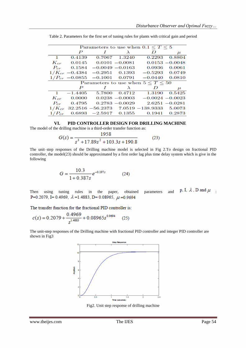
Table 2. Parameters for the first set of tuning rules for plants with critical gain and period
VI. PID CONTROLLER DESIGN FOR DRILLING MACHINE
The model of the drilling machine is a third-order transfer function as:
The unit–step responses of the Drilling machine model is selected in Fig 2.To design on fractional PID
controller, the model(23) should be approximated by a first order lag plus time delay system which is give in the
following
Then using tuning rules in the paper, obtained parameters and :
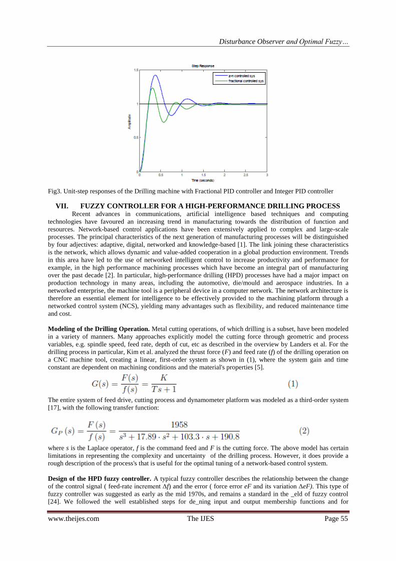
The unit-step responses of the Drilling machine with fractional PID controller and integer PID controller are
shown in Fig3
Fig2. Unit step response of drilling machine
Disturbance Observer and Optimal Fuzzy…
www.theijes.com The IJES Page 55
Fig3. Unit-step responses of the Drilling machine with Fractional PID controller and Integer PID controller
VII. FUZZY CONTROLLER FOR A HIGH-PERFORMANCE DRILLING PROCESS Recent advances in communications, artificial intelligence based techniques and computing
technologies have favoured an increasing trend in manufacturing towards the distribution of function and
resources. Network-based control applications have been extensively applied to complex and large-scale
processes. The principal characteristics of the next generation of manufacturing processes will be distinguished
by four adjectives: adaptive, digital, networked and knowledge-based [1]. The link joining these characteristics
is the network, which allows dynamic and value-added cooperation in a global production environment. Trends
in this area have led to the use of networked intelligent control to increase productivity and performance for
example, in the high performance machining processes which have become an integral part of manufacturing
over the past decade [2]. In particular, high-performance drilling (HPD) processes have had a major impact on
production technology in many areas, including the automotive, die/mould and aerospace industries. In a
networked enterprise, the machine tool is a peripheral device in a computer network. The network architecture is
therefore an essential element for intelligence to be effectively provided to the machining platform through a
networked control system (NCS), yielding many advantages such as flexibility, and reduced maintenance time
and cost.
Modeling of the Drilling Operation. Metal cutting operations, of which drilling is a subset, have been modeled
in a variety of manners. Many approaches explicitly model the cutting force through geometric and process
variables, e.g. spindle speed, feed rate, depth of cut, etc as described in the overview by Landers et al. For the
drilling process in particular, Kim et al. analyzed the thrust force (F) and feed rate (f) of the drilling operation on
a CNC machine tool, creating a linear, first-order system as shown in (1), where the system gain and time
constant are dependent on machining conditions and the material's properties [5].
The entire system of feed drive, cutting process and dynamometer platform was modeled as a third-order system
[17], with the following transfer function:
where s is the Laplace operator, f is the command feed and F is the cutting force. The above model has certain
limitations in representing the complexity and uncertainty of the drilling process. However, it does provide a
rough description of the process's that is useful for the optimal tuning of a network-based control system.
Design of the HPD fuzzy controller. A typical fuzzy controller describes the relationship between the change
of the control signal ( feed-rate increment Δf) and the error ( force error eF and its variation ΔeF). This type of
fuzzy controller was suggested as early as the mid 1970s, and remains a standard in the _eld of fuzzy control
[24]. We followed the well established steps for de_ning input and output membership functions and for
Disturbance Observer and Optimal Fuzzy…
www.theijes.com The IJES Page 56
constructing fuzzy-control rules in designing a two-input/one-output fuzzy-control system. The fuzzy
controller's core performs on-line actions to modify the feed rate. The manipulated action variable is the feed-
rate increment Δf as a fraction of the initial value programmed into the CNC. The reference force value Fr is
derived from a learning phase of uncontrolled drilling tests. For each sampling period k, the cutting-force error
and the variation in cutting-force error are calculated as:
where eF and ΔeF are calculated at each instant k. The output (u) and the error vectors are, respectively:
where e and ec are the discrete input variables, eF is the cutting-force error in newtons, ΔeF is the variation in
cutting-force error (in newtons) and Ke, Kce are scaling factors for the inputs error and variation in error,
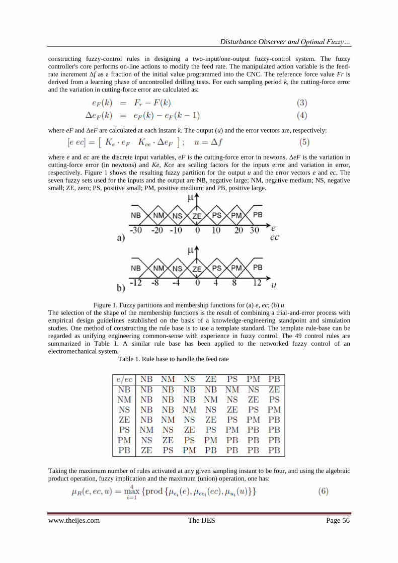
respectively. Figure 1 shows the resulting fuzzy partition for the output u and the error vectors e and ec. The
seven fuzzy sets used for the inputs and the output are NB, negative large; NM, negative medium; NS, negative
small; ZE, zero; PS, positive small; PM, positive medium; and PB, positive large.
Figure 1. Fuzzy partitions and membership functions for (a) e, ec; (b) u
The selection of the shape of the membership functions is the result of combining a trial-and-error process with
empirical design guidelines established on the basis of a knowledge-engineering standpoint and simulation
studies. One method of constructing the rule base is to use a template standard. The template rule-base can be
regarded as unifying engineering common-sense with experience in fuzzy control. The 49 control rules are
summarized in Table 1. A similar rule base has been applied to the networked fuzzy control of an
electromechanical system.
Table 1. Rule base to handle the feed rate
Taking the maximum number of rules activated at any given sampling instant to be four, and using the algebraic
product operation, fuzzy implication and the maximum (union) operation, one has:
Disturbance Observer and Optimal Fuzzy…
www.theijes.com The IJES Page 57
The crisp controller output, which changes the feed rate, is obtained by defuzzification. There are three basic
traditional methods: the maximum, mean-of-maxima (MOM) and centre-of-area (COA). We chose the COA
strategy for defuzzification because of its appropriate steady state performance, and its use as a standard method
in experimental and industrial fuzzy controllers. It is expressed as:
where u is the crisp value of ui for a given crisp input (e, ec).
The output-scaling factor (GC) multiplied by the crisp-control action generated at each sampling instant
provides the final actions that will be applied to the CNC machine tool's cutting parameters. Finally, the feed
rate f of the CNC drilling machine can be written as:
is identical to the PROFIBUS RS485 standard. The transmission rate can be increased up to 12Mbits/s with the
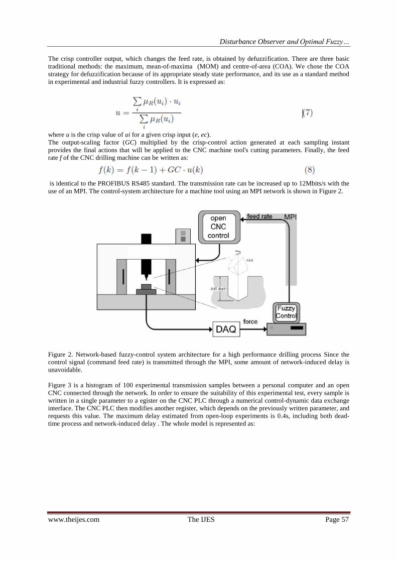
use of an MPI. The control-system architecture for a machine tool using an MPI network is shown in Figure 2.
Figure 2. Network-based fuzzy-control system architecture for a high performance drilling process Since the
control signal (command feed rate) is transmitted through the MPI, some amount of network-induced delay is
unavoidable.
Figure 3 is a histogram of 100 experimental transmission samples between a personal computer and an open
CNC connected through the network. In order to ensure the suitability of this experimental test, every sample is
written in a single parameter to a egister on the CNC PLC through a numerical control-dynamic data exchange
interface. The CNC PLC then modifies another register, which depends on the previously written parameter, and
requests this value. The maximum delay estimated from open-loop experiments is 0.4s, including both dead-
time process and network-induced delay . The whole model is represented as:

Disturbance Observer and Optimal Fuzzy…
www.theijes.com The IJES Page 58
Figure 3. Histogram of the transmission delay time over an MPI network
4.Experimental set-up and Fuzzy Control System. This briey explains the tuning and implementation of the
fuzzy controller that communicates with the open-architecture CNC through the MPI network. The data-
acquisition system consists of a dynamometer, a charge amplifier and hardware and software modules, as
depicted in Figure 4. The cutting forces are measured with a Kistler 9257B piezoelectric dynamometer mounted
between the workpiece and the machining table. The electric charge is then transmitted to the Kistler 5070A
four-channel charge amplifier. The interface hardware module consists of a connecting block and an AT-MIO-
16E-1 16-channel A/D acquisition card. The A/D device transforms the analogue signal into a digital signal such
that the Simulink program reads the three axial force components simultaneously, and processes and displays
these data. The Real-Time Windows Target (RTWT) allows for real-time execution of Simulink models.
Figure 4. Scheme of the experimental set-up and fuzzy-control system
The output of the fuzzy controller is connected to the process through a multipoint interface MPI with a default
transmission rate of 187.5 kbits/s. A CP5611 card connects the PC that implements the fuzzy-control system to
this network. The MPI messaging interface is a master-client relationship active station, and manages exchanges
with the Siemens S7 PLC. The system has two masters, the man-machine control MMC 103 with a numerical-
control kernel and a numerical-control unit NCU 573.3. Real- time targets are I/O devices utilizing their own
processors, running real-time tasks and communicating with the PC/RTW. These hardware and software tools
are used to create the integrated environment. Two simulation schemes in the same environment i.e, two
Simulink based models are used One is used for networked control system simulation i.e., linear and fuzzy

Disturbance Observer and Optimal Fuzzy…
www.theijes.com The IJES Page 59
controllers and the other for DAQ and controller implementation. This setup helps the real system to be
designed, implemented and verified as rapidly and easily as in the simulation.
5 Simulation. The control literature of the past few decades abounds in various performance criteria, with the
most significant being functions of time and error. The optimal tuning of the present fuzzy controller was based
on the \integral of the time weighted absolute error" (ITAE) performance index in order to obtain a short settling
time and overshoot-free time response. Other performance indices such as the \integral of the time weighted
squared error" (ITSE), \integral of the absolute error" (IAE) and the \integral of the time-squared weighted
squared error" (IT2SE) were also evaluated. Specifically, the ITAE penalizes long-duration transients and is very
sensitive to parameter variations in comparison with other criteria. Moreover, the ITAE criterion generally
produces smaller overshoots and oscillations than the IAE and ITSE criteria. Before experimental testing of the
control scheme, the performance of the fuzzy-control system was examined by simulation using Simulink as
depicted in Figure 5. The ITAE index describes how well the system responds to an outside disturbance. In this
study, a step in the force reference signal is considered a disturbance, and one attempts to assess how well the
system follows set
point changes using the ITAE criterion.
Figure 5. Overall model of the fuzzy-control system
The goal is to obtain the optimal parameters for the input scaling factors [Ke; Kce]OPT such that the ITAE
performance index has its minimum:
where T is the overall drilling time (i.e., time elapsed between tool entrance and exit) and Ovt is the overshoot of
the closed-loop dynamic response. The optimal tuning of the fuzzy controller is carried out using the input
scaling factors [Ke;Kce]OPT . While high values of Ke yield good responsiveness of the system (low steady-
state error and settling time), they also lead to poor stability (large overshoot). The fastest convergence is
obtained with low value of Kce. There are many methods for tuning fuzzy controllers, and an in-depth study of
them is beyond the scope of the present work.The optimal setting of the input scaling factors [Ke;Kce]OPT was
determined using the Nelder-Mead search algorithm. This is a numerical method for minimizing an objective
function in a multi-dimensional space. The resulting variable-size downhill simplex is corrected with a constant
small-size uphill simplex that climbs local gradients to local maxima to avoid entrapment in local minima. The
cost function was evaluated through simulation based on Equation (9). Initially [Ke;Kce]INIT = [1:0; 1:0] and
GC = 0.500, corresponding to an ITAE = 0.709 and an overshoot of 4.090%. The output scaling factor GC was
kept constant during the tuning procedure. The minimum ITAE = 0.469 was reached at [Ke;Kce]OPT = [0:0125;
0:0374]. The ITSE criterion was 0.292, the IT2SE criterion 0.164, and the overshoot Ovt 0.15%. The simulation
results are depicted in Figure 6. The system's step response with a setpoint of 1000 N is depicted in Figure 6(a).
As shown in the _gure, the cutting force is well regulated with respect to the reference value. Figure 6(b) shows
the control signal (feed rate modi_cation). The transient response is clearly improved after optimization
[Ke;Kce]OPT = [0:0125; 0:0374] relative to the initial scaling factors [Ke;Kce]INIT = [1:0; 1:0].

Disturbance Observer and Optimal Fuzzy…
www.theijes.com The IJES Page 60
Figure 6. Simulation results: (a) step response of the cutting force; (b) feed rate
There have been studies of constraints in communications from the control system viewpoint. Some have
analyzed the delays in a switched network control system with a defined latency time using the TCP/IP
transmission protocol. In general, these delays are modeled using such statistical techniques as negative
exponential distribution functions and Poisson and Markov chains.
Figure 8. Behaviour of the ITAE (solid line) and IT2SE (dashed line) performance indices in the presence of
delays
Experimental drilling tests were carried out on an HS1000 Kondia milling machine equipped with a Sinumerik
840D open-CNC controller. A 10-mm diameter Sandvik cutting tool was used for the drilling operations. The
workpiece material was GGG40 with a Brinell hardness of 233 HB. The nominal feed rate and spindle speed
were f0 = 100 mm/min and n0 = 870 rpm, respectively, with a maximum drill depth of 14 mm. The set point
was set at 1000 N. Photographs of the experimental setup are shown in Figures 2 and 5.
Figure 10. (a) Cutting force; (b) feed rate variations in uncontrolled drilling and drilling with a linear controller
(PID)
Disturbance Observer and Optimal Fuzzy…
www.theijes.com The IJES Page 61
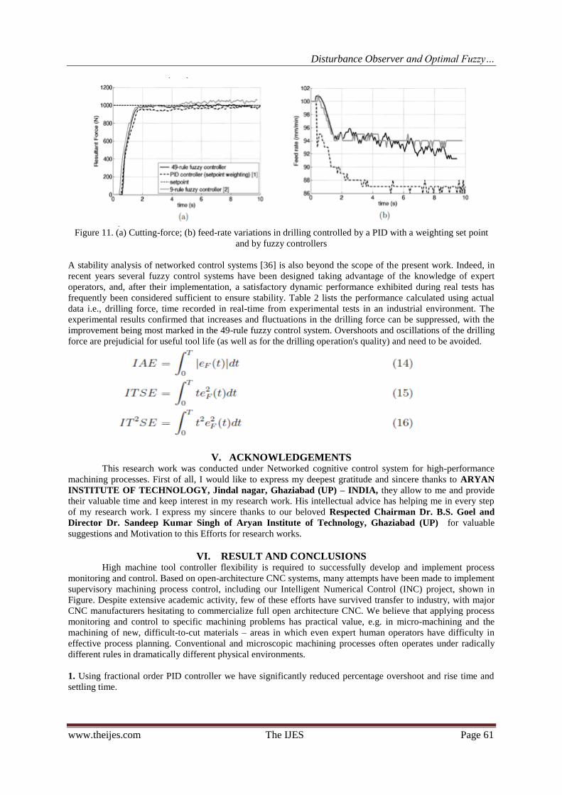
Figure 11. (a) Cutting-force; (b) feed-rate variations in drilling controlled by a PID with a weighting set point
and by fuzzy controllers
A stability analysis of networked control systems [36] is also beyond the scope of the present work. Indeed, in
recent years several fuzzy control systems have been designed taking advantage of the knowledge of expert
operators, and, after their implementation, a satisfactory dynamic performance exhibited during real tests has
frequently been considered sufficient to ensure stability. Table 2 lists the performance calculated using actual
data i.e., drilling force, time recorded in real-time from experimental tests in an industrial environment. The
experimental results confirmed that increases and fluctuations in the drilling force can be suppressed, with the
improvement being most marked in the 49-rule fuzzy control system. Overshoots and oscillations of the drilling
force are prejudicial for useful tool life (as well as for the drilling operation's quality) and need to be avoided.
V. ACKNOWLEDGEMENTS This research work was conducted under Networked cognitive control system for high-performance
machining processes. First of all, I would like to express my deepest gratitude and sincere thanks to ARYAN
INSTITUTE OF TECHNOLOGY, Jindal nagar, Ghaziabad (UP) – INDIA, they allow to me and provide
their valuable time and keep interest in my research work. His intellectual advice has helping me in every step
of my research work. I express my sincere thanks to our beloved Respected Chairman Dr. B.S. Goel and
Director Dr. Sandeep Kumar Singh of Aryan Institute of Technology, Ghaziabad (UP) for valuable
suggestions and Motivation to this Efforts for research works.
VI. RESULT AND CONCLUSIONS High machine tool controller flexibility is required to successfully develop and implement process
monitoring and control. Based on open-architecture CNC systems, many attempts have been made to implement
supervisory machining process control, including our Intelligent Numerical Control (INC) project, shown in
Figure. Despite extensive academic activity, few of these efforts have survived transfer to industry, with major
CNC manufacturers hesitating to commercialize full open architecture CNC. We believe that applying process
monitoring and control to specific machining problems has practical value, e.g. in micro-machining and the
machining of new, difficult-to-cut materials – areas in which even expert human operators have difficulty in
effective process planning. Conventional and microscopic machining processes often operates under radically
different rules in dramatically different physical environments.
1. Using fractional order PID controller we have significantly reduced percentage overshoot and rise time and
settling time.

Disturbance Observer and Optimal Fuzzy…
www.theijes.com The IJES Page 62
2. A comparison of time domain specifications peak overshoot, peak time ,rise time and settling time are
tabulated as given in Table 3. It is found very clearly that fractional order PID controller reduce the overshoot
by a large value. Settling time, rise time and peak time have also improved.
Table 1 : comparison between peak overshoot, peak time ,rise time and settling time
3. Again we have presented a 49-rule, two-input/one-output, fuzzy controller to regulate the force in drilling
processes while maximizing useful tool life.
4. The fuzzy-control system adjusts the feed as needed to regulate the drilling force using the CNC's own
resources to modify the feed rate and a dynamometer to measure the drilling force.
Table 2. Comparative study of the control strategies applied
5. The optimal setting of the input scaling factors [Ke;Kce]OPT was determined using the Nelder-Mead search
algorithm. This is a numerical method for minimizing an objective function in a multi-dimensional space.
6. The resulting variable-size downhill simplex is corrected with a constant small-size uphill simplex that climbs
local gradients to local maxima to avoid entrapment in local minima.
7. The cost function was evaluated through simulation based on Equation (9). Initially [Ke;Kce]INIT = [1:0;
1:0] and GC = 0.500, corresponding to an ITAE = 0.709 and an overshoot of 4.090%. The output scaling factor
GC was kept constant during the tuning procedure. The minimum ITAE = 0.469 was reached at [Ke;Kce]OPT =
[0:0125; 0:0374].
8. The ITSE criterion was 0.292, the IT2SE criterion 0.164, and the overshoot Ovt 0.15%. The simulation results
are depicted in Figure 6. The system's step response with a set point of 1000 N is depicted in Figure 6(a).
9. The cutting force is well regulated with respect to the reference value as shown in figure 6(b) which shows
the control signal feed rate modification.

Disturbance Observer and Optimal Fuzzy…
www.theijes.com The IJES Page 63
10. The transient response is clearly improved after optimization [Ke;Kce]OPT = [0:0125; 0:0374] relative to
the initial scaling factors [Ke;Kce]INIT = [1:0; 1:0].
In this research paper tuning rules inspired by those proposed by Ziegler and Nichols for integer PIDs are given
to tune fractional PID s and high performance of drilling fuzzy controller. Two different sets of fixed
performance specifications are used. On overall comparison, the optimum fuzzy controller gives the minimum
cutting time in high performance of drilling process. These data can be further used for other process.
REFERENCES [1] J. Wang, X. Xu, J. Sun, R. T. Li and W. S. Wang, Development of an NC controller for next generation CNCS, International
Journal of Innovative Computing, Information and Control, vol.4, no.3, pp.593-604, 2008.
[2]. A. Matsubara, “Research and Development on Intelligent Control of Machine Tools,” Proc. of 9th Int’l Conf. on Production
Engineering, Design, and Control (Keynote speech), pp. 10-12, 2009. [3]. S. Kurada and C. Bradley, “A review of machine vision sensors for tool condition monitoring,” Computers in Industry, 34-1, pp.
55-72,1997.
[4]. S. Ibaraki, A. Matsubara, and M. Morozumi, “Efficiency Comparison of Cutting Strategies for End Milling Processes under Feed
rate Scheduling,” Int’l J. of Automation Technology, 2-5, pp. 377-383, 2008.
[5]. B. Najafi and H. Hakim, “A comparative study of non-parametric spectral estimators for application in machine vibration
analysis,”Mechanical Systems and Signal Processing, 6-6, pp. 551-574, 1992. [6]. A. G. Rehorn, J. Jiang, P. E. Orban, and E. V. Bordatchev, “State-ofthe- art methods and results in tool condition monitoring: a
review,” Int’l J. of Advanced Manufacturing Technology, 26, pp. 693-710, 2005.
[7]. S. Y. Liang, R. L. Hecker, and R. G. Landers, “Machining process monitoring and control: The state-of-the-art,” Trans. of ASME, J. of Manufacturing Science and Engineering, 126-2, pp. 297-310, 2004.
[8]. D. E. Dimla, “Sensor signals for tool-wear monitoring in metal cutting operations – a review of methods,” Int’l J. of Machine Tools
and Manufacture, 40-8, pp. 1073-1098, 2000. [9]. K. Furutani, “Piezoelectric sensors,” J. of the Society of Instrument and Control Engineers, 45-4, pp. 296-301, 2006 (in Japanese).
[10]. D. Kono, A. Matsubara, I. Yamaji, and T. Fujita, “High-precision machining by measurement and compensation of motion error,”
Proc. of 4th Int’l Conf. on Leading Edge Manufacturing in 21st Century, pp. 809-812, 2007. [11]. Zhang, Q., Adaptive observer for multiple-input-multiple-output (MIMO) linear time-varying systems, Automatic Control, IEEE
Transactions on, vol.47, pp. 525-529, 2002.
[12]. Kubota, H. and Sato, I. and Tamura, Y. and Matsuse, K. and Ohta, H. and Hori, Y., Stable operation of adaptive observer based sensorless induction motor drives in regenerating mode at low speeds, Industry Applications Conference, 2001. Thirty-Sixth IAS
Annual Meeting. Conference Record of the 2001 IEEE, vol.1, pp. 569-474, 2002
[13]. S. Dongfeng and N. N. Gindy, Industrial applications of online machining process monitoring system, IEEE/ASME Trans. on Mechatronics, vol.12, no.5, pp.561-564, 2007.
[14]. Tipsuwan and M. Y. Chow, Gain scheduler middleware: A methodology to enable existing controllers for networked control and
teleoperation { Part I: Networked control, IEEE Trans. on Industrial Electronics, vol.51, no.6, pp.1218-1227, 2004. [15]. Y. Sheng and M. Tomizuka, Intelligent modeling of thrust force in drilling process, Journal of
Dynamic Systems Measurement and Control-Transactions of the ASME, vol.128, no.4, pp.846-855, 2006.
[16]. S. Y. Liang, R. L. Hecker and R. G. Landers, Machining process monitoring and control: The state-of-the-art, Journal of Manufacturing Science and Engineering, Transactions of the ASME, vol.126,no.2, pp.297-310, 2004.
[17]. . Mendez-Monroy and H. Benitez-Perez, Supervisory fuzzy control for networked control systems,ICIC Express Letters, vol.3, no.2,
pp.233-240, 2009. [18]. X. M. Zhu, C. C. Hua and S. Wang, State feedback controller design of networked control sys
tems with time delay in the plant, International Journal of Innovative Computing, Information andControl, vol.4, no.2, pp.283-290,
2008. [19]. J. C. Lagarias, J. A. Reeds, M. H. Wright and P. E. Wright, Convergence properties of the Nelder-Mead simplex method in low
dimensions, SIAM Journal of Optimization, vol.9, no.1, pp.112-147,1998. [20]. M. Zhang and S. Hu, Fuzzy control of nonlinear systems with input saturation using multiple model structure, ICIC Express Letters,
vol.2, no.2, pp.131-136, 2008.
[21]. R. E. Haber-Guerra, R. Haber-Haber, D. M. Andr_es and A. A. Palomar, Networked fuzzy control system for a high-performance drilling process, Journal of Manufacturing Science and Engineering,Transactions of the ASME, vol.130, no.3, pp.0310091-
0310096, 2008.
[22]. R. E. Haber, A. Gajate and R. del Toro, Optimal fuzzy control system using the cross-entropy method. A case study of a drilling process, Information Sciences, vol.180, no.14, pp.2777-2792, 2010.
[23]. R. E. Haber, R. Haber-Haber, A. Jimenez and R. Galan, An optimal fuzzy control system in a network environment based on
simulated annealing. An application to a drilling process, Applied Computing, vol.9, no.3, pp.889-895, 2009.