ditcher assemblies
TRANSCRIPT

PARTS LISTING WITHMOUNTING INSTRUCTIONS
DITCHERASSEMBLIES
06000002
Tiger Corporation3301 N. Louise Ave.
Sioux Falls, SD 571071-800-843-68491-605-336-7900
www.tiger-mowers.com
Current as of 8/31/2021

TO THE OWNER / OPERATOR / DEALERAll implements with moving parts are potentially hazardous. There is no substitute for a cautious,
safe-minded operator who recognizes the potential hazards and follows reasonable safety practices.The manufacturer has designed this implement to be used with all its safety equipment properlyattached to minimize the chance of accidents.
BEFORE YOU START!! Read the safety messages on the implement and shown in this manual.Observe the rules of safety and use common sense!
READ AND UNDERSTAND THIS MANUAL! Non–English speaking operators will need to GETTHE MANUAL TRANSLATED as needed!
Warranty Information: Read and understand the complete Warranty Statement found in this manual. Fill out theWarranty Registration form in full and return it within 90 days. Make certain the Serial Number of the machine isrecorded on the Warranty Card, and form that you retain.

FORWARD
This manual contains information about many features of the Tiger mowingand roadside maintenance equipment. Some of these include: Safety precautions,Assembly instructions, Operations, Maintenance and Parts. This manual will alsoassist you in the proper break-in, daily care, and troubleshooting of your newmower.
We recommend that you read carefully the entire manual before operating theunit. Also, time spent in becoming fully acquainted with its performance features,adjustments, and maintenance schedules will be repaid in a long and satisfactorylife of the equipment.
Troubleshooting - Please, before you call, help us to help you!Please look at the equipment to observe what is happening, then:• Classify the problem
• Hydraulic, electrical or mechanical - Read the trouble shooting section• Tractor or Truck chassis - Contact vehicle dealer
• If unable to correct the problem yourself, contact your local Tiger Dealer after gathering:
• Machine model _______________________• Serial number ________________________• Dealer name _________________________• Detailed information about the problem including results of troubleshooting
Attention Owner / Operator / Dealer: It is your obligation to read, and understand,the warranty information section located at the back of this manual denoting that thepurchaser understands the safety issues relating to this machine and has receivedand will read a copy of this manual.
If at any time, you have a service problem with your Tiger mower, Contactyour local dealer for service and parts needed.
MANUFACTURED BY: DISTRIBUTED BY:Tiger Corporation _____________________3301 N. Louise Ave. _____________________Sioux Falls, SD 57107 1-_____-_____-________1-800-843-6849 1-_____-_____-________1-605-336-7900www.tiger-mowers.com


PARTSSECTION
DITCHER

Ditcher 7 - 2
TABLE OF CONTENTS

Ditcher 7 - 3
TABLE OF CONTENTS
DITCHER PARTS PAGE
MOUNTING INSTRUCTIONS 7-4
DRAFT BEAM - CABLE LIFT 7-12
CABLE LIFT ASSEMBLY 7-14
CABLE LIFT ASSEMBLY - DD 7-16
DRAFT BEAM - COMBO LIFT 7-18
COMBO LIFT ASSEMBLY 7-20
COMBO LIFT ASSEMBLY - DD 7-22
MAIN BOOM ARM MOUNT 7-24
MAIN BOOM ARM MOUNT - DD 7-26
SABER SECONDARY BOOM ARM MOUNT 7-28
BENGAL SECONDARY BOOM ARM MOUNT 7-30
BENGAL BRUTE SECONDARY BOOM ARM MOUNT 7-32
DITCHER HEAD STANDARD ROTATION 7-34
DITCHER HEAD REVERSE ROTATION 7-36
LIFT VALVE - 3 SPOOL, POWER BEYOND 7-38
LIFT VALVE - 3 SPOOL, OPEN CENTER 7-40
GEAR REDUCER 7-42
MOTOR BREAKDOWN - 06504014 7-44
MOTOR BREAKDOWN - 06504063 7-46
9-26-07

Ditcher 7 - 4
MOUNTING INSTRUCTIONS
HIGH PRESSURE SIDE MOUNTED DITCHERCheck complete shipment against packing list to make sure there are no shortages.Make certain tractor model is the appropriate one for the ditcher recieved. Use floorjack or hoist to lift or raise heavy parts whenever possible if mentioned or not. Readentire instructions completely before mounting tractor.
PRELIMINARY INSTRUCTIONSINSTALLING O-RING FITTINGSa. Straight swivel: Install swivel and tighten.b. 45º and 90º swivels (Fig. A) : Back O-ring nut and washer (A) up against swivel
body (B). Install swivel and turn in until swivel is in right direction and O-ringcontact is made. Hold swivel in set direction with wrench and turn O-ring nut awayfrom swivel body and tighten.
INSTALLING NATIONAL PIPE FITTINGSWhenever installing a pipe fitting, wrap threads clockwise looking at end with Teflontape. In this way the tape will be tightened when installed. Note: It is not necessaryto tape O-ring fittings or those installed in swivels.
GEASING WEAR POINTSBosses and pins: Inject grease until it appears at joints.
MOUNTING INSTRUCTIONSINBOARD 3 X 10 CYLINDER (FIG. B) (FIG. D)a. Install adjustable 1/2” o-ring breather (F) in butt port.b. Install adjustable 1/2” o-ring M x 90º-FP elbow (G) in rod port. Fitting should be
adjusted to face toward butt end of cylinder.c. Install 1/2” x .093 restricter (H) in 90º fitting.d. Turn clevis on to piston rod until tight against shoulder and lock into place with
locking bolt.

Ditcher 7 - 5
MOUNTING INSTRUCTIONS
e. Install inboard cylinder in main frame mast with 1” x 7” pin, 1” flatwashers, and pinclips. (Fig. B)
DRAFT BEAM MOUNTING (FIG. C)a. Pull inboard cylinder piston rod down to extreme extended position.
Figure C
Figure B

Ditcher 7 - 6
b. Slide draft beam under cylinder, align clevis hole with draft beam hole (1”) nearesttractor and install 1” x 3” pin in draft beam hole and clevis.
c. Using inboard cylinder as a pivot point, slide draft beam under tractor and installdraft beam pin (1-1/2” x 15-3/4”). Align hole in draft beam pin with holes in mainframe boss and install 7/16” x 3-1/4” capscrew, lockwasher, and nut.
OUTBOARD 3 X 18 CYLINDER (FIG. F)a. Install adjustable 1/2” O-ring M x 90º FP elbow (I) in butt port. Elbow should point
toward rod port.b. Install adjustable 1/2” O-ring breather (J) in rod port.c. Install 1/2” x 0.093 restrictor (K) in 90º fitting.d. Install outboard cylinder on draft beam as shown in Fig. C Install 1” x 3” pin in
draft beam hole and cylinder. Secure with R-clips.
DECK MOUNTING AND LIFT ASSEMBLY (FIG. D)a. Install upper sheave bracket on outboard cylinder. Tighten securely against
piston rod shoulder, tighten set screw, and align with draft beam.b. Install lower sheave bracket on draft beam with 3/4” x 3” capscrew and two nuts.c. Align ditcher boom with draft beam mounting ears and install boom mounting pin
(1-1/2” x 17”). Align hole in boom mounting pin with holes in boss and lock intoplace with 7/16” x 3-1/4” capscrew, lockwasher, and nut.
MOUNTING INSTRUCTIONS

Ditcher 7 - 7
MOUNTING INSTRUCTIONS
d. Pass lift cable through upper sheave bracket and attach to turn buckle with turnbuckle pin and cotter key.
e. Attach turn buckle to draft beam with turn buckle pin and cotter key.f. Place lift cable in lower sheave bracket and install sheave with 3/4” x 2-1/2” pin
(with grease zerk) and R-clip.g. Install sheave in upper sheave bracket with cable over sheave. Insert 3/4” x 3”
pin (with grease zerk) and R-clip.h. Attach cable to ditcher boom with shackle and tighten shackle and tighten
shackle pin securely. DO NOT TIGHTEN TURN BUCKLE AT THIS TIME.
DEFLECTOR CHUTE CYLINDER 2 X 6 (FIG. E) (FIG. F)a. Install (2) two swivel 1/2” adjustable O-ring x 1/2” FPX - 90º in both ports with
fittings pointing to the butt of the cylinder.b. Install deflector chute cylinder with (4) four 1/4” spacers onto ditcher bonnets and
secure with 1” x 3-1/2” pins and R-clips.

Ditcher 7 - 8
MOUNTING INSTRUCTIONS
LIFT CONTROL FEEDLINES (FIG. F)a. Install a hose 1/2” x (31” - valve mounted on mast with cabs, 43” - valve stand
mounted on mast without cabs, 38” - Ford non-cab, 48” - valve mounted underthe cab) MP-MP inbetween the inboard cylinder restrictor and the bottom fittingor inner fitting on control valve.
b. Install a hose 1/2” x (48” - valve mounted under the cab, 60” - cabs and non-cabsif valve mounted on mast) MP-MP inbetween the outboard cylinder restrictor andthe middle fitting on control valve.
c. Install 1/2” quick couplers on (2) two hose 1/2” x 120” (MP-MP) (140” if valve ismounted under the cab). Attach hoses between the deflector chute cylinder andthe top or outer fittings. The butt end hose of the cylinder connects with the backor control side of the control valve as shown.

Ditcher 7 - 9
MOUNTING INSTRUCTIONS
DECK FEEDLINE (FIG. G)a. If swivel fitting 1” MP x 1” FPX - 90º are attached to preformed tees on solenoid
valve mower side, replace with swivel fitting 1” MP x 1” FPX - 45º.b. Install a swivel 1” adjustable O-ring x 1” FPX - 45º to the ditcher motor port that is
closer to the ditcher head.c. Install a swivel 1” O-ring x 1” FPX to the ditcher motor port that is further out from
the ditcher head, with a swivel 1” MP x 1 FPX - 45º.d. Install a hose 1” x 111” (MP-MP) to the first set of fitting on the ditcher motor to the
bottom fitting on the solenoid valve mounted on the main frame mast.e. Install a hose 1” x 111” (MP-MP) between the single fitting on the ditcher motor to
the top of the solenoid valve.f. Install split hoses using hose clamps on motor hose at draft beam edge of boom.g. Install hose bracket to ditcher boom and secure with 1/2” hex nut.
Ditcher 7 - 10
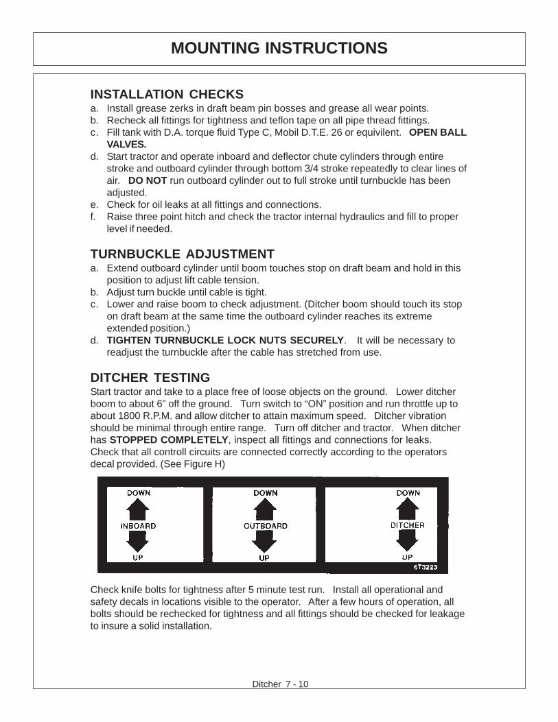
INSTALLATION CHECKSa. Install grease zerks in draft beam pin bosses and grease all wear points.b. Recheck all fittings for tightness and teflon tape on all pipe thread fittings.c. Fill tank with D.A. torque fluid Type C, Mobil D.T.E. 26 or equivilent. OPEN BALL
VALVES.d. Start tractor and operate inboard and deflector chute cylinders through entire
stroke and outboard cylinder through bottom 3/4 stroke repeatedly to clear lines ofair. DO NOT run outboard cylinder out to full stroke until turnbuckle has beenadjusted.
e. Check for oil leaks at all fittings and connections.f. Raise three point hitch and check the tractor internal hydraulics and fill to proper
level if needed.
TURNBUCKLE ADJUSTMENTa. Extend outboard cylinder until boom touches stop on draft beam and hold in this
position to adjust lift cable tension.b. Adjust turn buckle until cable is tight.c. Lower and raise boom to check adjustment. (Ditcher boom should touch its stop
on draft beam at the same time the outboard cylinder reaches its extremeextended position.)
d. TIGHTEN TURNBUCKLE LOCK NUTS SECURELY. It will be necessary toreadjust the turnbuckle after the cable has stretched from use.
DITCHER TESTINGStart tractor and take to a place free of loose objects on the ground. Lower ditcherboom to about 6” off the ground. Turn switch to “ON” position and run throttle up toabout 1800 R.P.M. and allow ditcher to attain maximum speed. Ditcher vibrationshould be minimal through entire range. Turn off ditcher and tractor. When ditcherhas STOPPED COMPLETELY, inspect all fittings and connections for leaks.Check that all controll circuits are connected correctly according to the operatorsdecal provided. (See Figure H)
MOUNTING INSTRUCTIONS
Check knife bolts for tightness after 5 minute test run. Install all operational andsafety decals in locations visible to the operator. After a few hours of operation, allbolts should be rechecked for tightness and all fittings should be checked for leakageto insure a solid installation.

Ditcher 7 - 11

Ditcher 7 - 12
DRAFT BEAM - CABLE LIFT

Ditcher 7 - 13
DRAFT BEAM - CABLE LIFT
ITEM PART NO. QTY. DESCRIPTION
1 6T0103A 1 DRAFT BEAM (STD 25 LB, 45 3/8”)6T0103E OPT. DRAFT BEAM (EXTENDED 6” 4WD)6T0103L OPT. DRAFT BEAM (EXTENDED 15”)6T0105 OPT. DRAFT BEAM (STD WITH TRAVEL LOCK)6T0108 OPT. DRAFT BEAM (30 LB CHANNEL, 45 3/8”)
2 6T0150 1 CYLINDER 3” X 18”3 6T0151R 1 CYLINDER 3” X 10”4 6T0100 1 LOWER SHEAVE BRACKET5 6T0101 1 UPPER SHEAVE BRACKET6 33768 2 SHEAVE7 6T0110 1 LIFT CABLE (STD 1/2” X 87 1/2”)
6T0110E OPT. LIFT CABLE (EXTENDED 6” 4WD)6T0110L OPT. LIFT CABLE (EXTENDED 15”)
8 6T0115 1 TURN BUCKLE9 6T0112 1 SHACKLE WITH PIN10 6T2999 1 OUTER DRAFT BEAM PIN 1 1/2” X 14 1/2”11 6T3001 1 INNER DRAFT BEAM PIN 1 1/2” X 15 3/4”12 6T3005 1 PIN ,1” W/ CAP13 TB1033 2 CLEVIS PIN 1” X 4”14 6T3004 1 R - CLIP 3/16”15 6T3010 1 UPPER SHEAVE PIN WITH ZERK 3/4” X 3”16 6T3009 1 LOWER SHEAVE PIN WITH ZERK 3/4” X 2 1/2”17 27849 2 ROLL PIN 3/16” X 1 3/4”18 6T2272 1 SET SCREW 3/8” X 1/2”19 6T3211 1 GREASE ZERK 1/8” STRAIGHT20 21836 1 CAPSCREW 3/4” X 3”21 21688 2 CAPSCREW 7/16” X 3 1/4”22 21825 2 HEX NUT 3/4”23 21677 2 NYLOCK NUT 7/16”24 22023 1 FLAT WASHER 1”25 6T0104N 2 SHEAVE PIN BUSHING 1” OD X 3/4” ID26 21833 1 CAPSCREW 3/4” X 2 1/4”27 22021 1 FLAT WASHER 3/4”28 21993 1 LOCK WASHER 3/4”29 06537021 4 ROLL PIN30 6T0106 1 TRAVEL LOCK BRACKET31 6T4258 1 BREATHER 1/2”32 34396 2 RESTRICTOR33 34244 2 ELBOW FITTING 1/2”34 * REF. MAIN FRAME REFER TO TRACTOR PARTS SECTION

Ditcher 7 - 14
CABLE LIFT ASSEMBLY

Ditcher 7 - 15
CABLE LIFT ASSEMBLY
ITEM PART NO. QTY. DESCRIPTION
1 * REF DRAFT BEAM - REFER TO DRAFT BEAM SECTION2 23235B 1 SIDE DITCHER BOOM3 21727 1 NYLOCK NUT, 1/24 6T7024 1 HOSE CLAMP5 26142A 1 KEY,1/2 X 1/2 X 26 31869 1 GEAR REDUCER7 34175 1 HOSE, 1 x 418 TF4852 2 FLANGE KIT9 06504014 1 MOTOR,(M365-1 1/2" GEAR)10 34176 1 HOSE, 1 x 14911 21732 4 CAPSCREW, 1/2 x 1 3/4,NC12 21990 12 LOCKWASHER, 1/2"13 21725 8 HEX NUT, 1/2" NC14 42025 1 SPACER15 31875 1 SPROCKET16 21825 4 HEX NUT,3/4,NC17 21993 4 LOCKWASHER,3/4",GR 818 22021 4 FLATWASHER,3/4"19 21735 4 CAPSCREW, 1/2 x 2 1/2,NC20 6T7004 1 CHAIN COUPLING21 21835 4 CAPSCREW, 3/4 x 2 3/4,NC22 * REF DITCHER HEAD - REFER TO HEAD ASSY23 6T2267 4 CARRIAGE BOLT, 1/2" x 2" NF, GR824 22018 4 FLATWASHER,1/2",WIDE25 6T7022 1 CYLINDER, 2 x 626 30431 2 HOSE, 1/4 x 18227 6T0158 2 SWIVEL FITTING28 06537021 4 ROLLPIN,5mm29 TB1033 2 PIN,CLEVIS30 6T7018 4 SPACER31 * REF PIN - REFER TO DRAFT BEAM SECTION32 * REF LOCKWASHER - REFER TO DRAFT BEAM SECTION33 * REF HEX NUT - REFER TO DRAFT BEAM SECTION34 * REF CAPSCREW - REFER TO DRAFT BEAM SECTION

Ditcher 7 - 16
CABLE LIFT ASSEMBLY - DD

Ditcher 7 - 17
CABLE LIFT ASSEMBLY - DD
ITEM PART NO. QTY. DESCRIPTION
1 6T0103A 1 DRAFT BEAM (STD 25 LB, 45 3/8”)6T0103E OPT. DRAFT BEAM (EXTENDED 6” 4WD)6T0103L OPT. DRAFT BEAM (EXTENDED 15”)6T0105 OPT. DRAFT BEAM (STD WITH TRAVEL LOCK)6T0108 OPT. DRAFT BEAM (30 LB CHANNEL, 45 3/8”)
2 23235B 1 DITCHER,SIDE BOOM,HP3 21727 1 NYLOCK NUT,1/2 NC4 6T7024 1 BRKT,HOSE,DITCR5 6T7005 1 SPROCKET,1-1/2 KEYED,DITCR6 21825 4 HEX NUT,3/4 NC7 21993 4 LOCKWASHER,3/4,GR 88 21734 4 CAPSCREW,1/2 x 2-1/4,NC9 6T7004 1 CHAIN,COUPLING (6018)10 21835 4 CAPSCREW,3/4 x 2-3/4,NC11 * REF DITCHER HEAD - REFER TO HEAD ASSY12 6T2267 4 CARRIAGE BOLT,1/2 x 1-1/2,NC13 22018 8 FLATWASHER,1/2,WIDE14 21990 8 LOCKWASHER,1/215 21725 8 HEX NUT,1/2,NC16 6T7022 1 CYLINDER,2 x 617 34026 2 HOSE,1/4 x 18218 32810 2 ELBOW,1/2ORB x 3/8MJ90 ADJ19 TB1033 2 PIN,CLEVIS20 06537021 4 ROLLPIN,5mm21 6T7018 4 SPACER22 * REF REFER TO DRAFT BEAM SECTION23 * REF REFER TO DRAFT BEAM SECTION24 * REF REFER TO DRAFT BEAM SECTION25 * REF REFER TO DRAFT BEAM SECTION26 26142A 1 KEY,1/2 x 1/2 x 227 06504063 1 MOTOR,DITCHER,EATON28 33554 2 ELBOW,1MOR x 1MJIC,4529 06500394 2 HOSE,1 x 120

Ditcher 7 - 18
DRAFT BEAM - COMBO LIFT

Ditcher 7 - 19
ITEM PART NO. QTY. DESCRIPTION
1 06350001 REF COMBO DRAFT BEAM - STD DTY ROTARY31063 * COMBO DRAFT BEAM - HVY DTY ROTARY32143 * COMBO DRAFT BEAM - STD DTY FLAIL28955D * COMBO DRAFT BEAM - HVY DTY FLAIL
2 6T0151R 1 HYD. CYLINDER 3” X 10”3 32215 1 HYD. CYLINDER 3” X 12” - STD DTY
25343 REF HYD. CYLINDER 3” X 12” - HVY DTY4 TF4500A 1 PIVOT ARM5 TF4507B 1 RIGHT LINKAGE ARM6 TF4506B 1 LEFT LINKAGE ARM7 30126B 2 PIN, HEAD PIVOT8 6T3001 1 PIN, BEAM PIVOT9 TF4519 2 PIN, LINKAGE10 TB1033 3 PIN, CLEVIS11 06537021 6 ROLLPIN12 6T3005 1 PIN,1” W/ CAP13 6T3004 1 R-CLIP HAIRPIN14 6T2614 1 FLATWASHER 1”15 TB3010 8 BUSHING 1”16 22847 2 BOSS, LINKAGE PIN17 22076 1 SPACER, HYD. CYLINDER 1/4”18 22077 1 SPACER, HYD. CYLINDER 5/16”19 6T3207 6 GREASE ZERK 1/4”20 6T3211 3 GREASE ZERK 1/8”21 6T4258 1 BREATHER 1/2”22 34244 3 ELBOW FITTING 1/2”23 34396 3 SWIVEL RESTRICTOR24 21688 3 CAPSCREW 7/16” X 3 1/4”25 21675 3 HEX NUT 7/16”26 21635 2 CAPSCREW 3/8” X 2 1/4”27 21625 2 HEX NUT 3/8”28 21831 1 CAPSCREW 3/4” X 1 3/4”29 21825 1 HEX NUT 3/4”30 06700095 1 CYLINDER SPACER W/SET SCREW31 * REF REFER TO MAIN FRAME
NOTES: 1. ITEM 30 IS USED ON THE GLAND END OF ITEM 2 (AS NEEDED)
2. ORIENTATION OF ITEM 4 IS CRITICAL
DRAFT BEAM - COMBO LIFT

Ditcher 7 - 20
COMBO LIFT ASSY

Ditcher 7 - 21
COMBO LIFT ASSY
ITEM PART NO. QTY. DESCRIPTION
1 * REF DRAFT BEAM - REF TO DRAFT BEAM SECTION2 * REF CYLINDER - REF TO DRAFT BEAM SECTION3 21825 5 HEX NUT,3/4,NC4 6T2310 1 CAPSCREW, 3/4 x 6 1/2,NC5 30281 1 SIDE DITCHER BOOM (STANDARD DUTY)
32507 1 SIDE DITCHER BOOM (HEAVY DUTY)6 21675 2 HEX NUT, 7/167 21989 2 LOCKWASHER, 7/16"8 21688 2 CAPSCREW, 7/16 x 3 1/4,NC9 * REF PIN,SWIVEL - REF TO DRAFT BEAM SECTION10 21727 1 NYLOCK NUT, 1/211 6T7024 1 HOSE CLAMP (ROTARY DITCHER)12 26142A 1 KEY,1/2 X 1/2 X 213 31869 1 GEAR REDUCER14 34175 1 HOSE, 1 x 141 (STANDARD DUTY)15 TF4852 2 FLANGE KIT16 06504014 1 MOTOR,(M365-1 1/2" GEAR)17 34176 1 HOSE, 1 x 149 (STANDARD DUTY)18 21732 4 CAPSCREW, 1/2 x 1 3/4,NC19 21990 12 LOCKWASHER, 1/2"20 21725 8 HEX NUT, 1/2" NC21 42025 1 SPACER22 31875 1 SPROCKET23 21993 4 LOCKWASHER,3/4",GR 824 22021 4 FLATWASHER,3/4"25 21735 4 CAPSCREW, 1/2 x 2 1/2,NC26 21635 2 CAPSCREW,3/8x2 1/4,NC27 21988 2 LOCKWASHER,3/8"28 21625 2 HEX NUT,3/8",NC29 TF4519 2 PIN,T3F LNKGE30 33623 1 SWING ARM,DITCHER ASSY31 TF4500A 1 ARM, PIVOT, NEW STYLE32 6T7004 1 COUPLER CHAIN33 21835 4 CAPSCREW, 3/4 x 2 3/4,NC34 6T2267 4 CARRIAGE BOLT, 1/2" x 2" NF, GR835 * REF DITCHER HEAD - REFER TO HEAD ASSY36 22018 1 FLATWASHER,1/2",WIDE37 6T7022 1 CYLINDER, 2 x 638 30431 2 HOSE, 1/4 x 182 (STANDARD DUTY)
34944 2 HOSE, 1/4 x 190 (HEAVY DUTY)39 6T0158 2 SWIVEL FITTING40 TB1033 2 PIN,CLEVIS41 06537021 4 ROLLPIN,5mm42 6T7018 4 SPACER43 34943 2 ELBOW (HEAVY DUTY)44 34945 1 HOSE, 1 x 140 (HEAVY DUTY)45 34942 1 HOSE, 1 x 133 (HEAVY DUTY)

Ditcher 7 - 22
COMBO LIFT ASSEMBLY - DD

Ditcher 7 - 23
COMBO LIFT ASSEMBLY - DD
ITEM PART NO. QTY. DESCRIPTION
1 * REF. DRAFT BEAM - REFER TO DRAFT BEAM ASSY2 * REF. PIN,SWIVEL - REFER TO DRAFT BEAM ASSY3 21688 2 CAPSCREW,7/16 x 3-1/44 21677 2 NYLOCK NUT,7/16,NC5 30281 1 STANDARD DUTY SIDE DITCHER BOOM
32507 * HEAVY DUTY SIDE DITCHER BOOM6 6T7024 1 HOSE CLAMP7 21727 1 NYLOCK NUT,1/2,NC8 6T7005 1 SPROCKET,1-1/2 KEYED,DITCR9 21825 4 HEX NUT,3/4,NC10 21993 4 LOCKWASHER,3/4,GR 811 21734 4 CAPSCREW,1/2 x 2-1/4,NC12 6T7004 1 CHAIN,COUPLING13 21835 4 CAPSCREW,3/4 x 2-3/4,NC14 * REF DITCHER HEAD - REFER TO HEAD ASSY15 6T2267 4 CARRIAGE BOLT,1/2 x 1-1/2,NC16 22018 8 FLATWASHER,1/2,WIDE17 21990 8 LOCKWASHER,1/218 21725 8 HEX NUT,1/2,NC19 34026 2 HOSE,1/4 x 18220 32810 2 ELBOW,1/2ORB x 3/8MJ90 ADJ21 6T7022 1 CYLINDER,2 x 622 TB1033 2 PIN,CLEVIS23 06537021 4 ROLLPIN,5mm24 6T7018 4 SPACER25 TF4500A 1 ARM,PIVOT26 33623 1 SWING ARM,DITCHER ASSY27 * REF NYLOCK NUT - REFER TO DRAFT BEAM ASSY28 * REF CAPSCREW - REFER TO DRAFT BEAM ASSY29 * REF PIN - REFER TO DRAFT BEAM ASSY30 26142A 1 KEY,1/2 x 1/2 x 231 06504063 1 MOTOR,DITCHER,EATON32 33554 2 ELBOW,1MORB x 1MJIC,4533 06500372 1 HOSE,1 x 14334 06500395 1 HOSE,1 x 149

DITCHER BERM DRAFT BEAM
© 2021 Alamo Group Inc.
Ditcher 7-24

DITCHER BERM DRAFT BEAM
© 2021 Alamo Group Inc.
Ditcher 7-25
1 06350016 DRAFT BEAM,BERM,TM,SD 106350019 DRAFT BEAM,BERM,TM,HD
2 23833A TILT LINK, 9030, T3F,RT 13 23829 PIN,1.00x5.19,W/Ø.44,CAP 14 21635 CAPSCREW,3/8x2 1/4,NC 15 21627 NYLOCK NUT,3/8”,NC 16 TF4514A PIN,1.50x4.50,W/Ø.47,CAP,PULL 27 21688 CAPSCREW, 7/16 x 3 1/4,NC 28 21677 NYLOCK NUT,7/16 NC 29 6T0150 CYLINDER,3X18 110 06501037 CYLINDER,3X8,180 111 23827C PIN,1.00x4.94,W/Ø.22,CAP 112 TB1023 ROLLPIN,7/32” X 2” 113 6T2614 FLATWASHER,1”,SAE 114 06537021 ROLL PIN, 5MM x 50MM 815 TB1033 PIN,CLEVIS,1x4 416 TB3010 BUSHING,1 217 06350036 BOOM,DITCHER,SIDE,SD,BERM 1 06350037 BOOM,DITCHER,SIDE,XD,BERM 118 6T7024 HOSE CLAMP (ROTARY DITCHER) 119 21727 NYLOCK NUT,1/2,NC 120 06501455 HOSE,#16x122(16FJXx16FJX) 121 06501454 HOSE,#16x121(16FJXx16FJX) 122 21732 CAPSCREW, 1/2 x 1 3/4,NC 423 21990 LOCKWASHER, 1/2” 824 33554 ELBOW,1ORBX1FJX45 225 06504063 MOTOR,DITCHER,EATON 126 31869 GEAR REDUCER,DITCHER,2 KEYED 127 42025 PLATE,SPACER,DITCHER 128 6t7005 SPROCKET,1-1/2 KEYED,DITCR 129 21725 HEX NUT, 1/2” NC 430 21734 CAPSCREW,1/2x2 1/4,NC,GR 8 431 21835 CAPSCREW, 3/4 x 2 3/4,NC 432 21993 LOCKWASHER,3/4”,GR 8 433 21825 HEX NUT,3/4,NC 434 6T7004 CHAIN,COUPLING (6018) 135 DITCHER HEAD (SEE DITCHER HEAD PAGE) 136 6T7018 SPACER 437 6t7022 CYLINDER,2X6,DITCHER 138 32810 ELBOW, 1/2 X 3/8” 239 6T3207 GREASE ZERK, 1/4” 240 06501456 HOSE,#4x232(6FJXx8MB) 2

Ditcher 7 - 26
MAIN BOOM ARM MOUNT

Ditcher 7 - 27
MAIN BOOM ARM MOUNT
ITEM PART NO. QTY. DESCRIPTION
1 22726A 1 BOOM DITCHER MOUNTING HEAD2 06504014 1 MOTOR,DITCHER3 31869 1 GEAR REDUCER4 31875 1 SPROCKET5 6T7004 1 CHAIN,COUPLING6 26142A 1 KEY,1/2 x 1/2 x 27 6T7022 1 CYLINDER,2 x 68 6T7018 4 SPACER9 TB1036 1 CLEVIS PIN10 TF1023 2 ROLL PIN11 TB1025D 1 SECONDARY BOOM PIN12 31885 2 HOSE,1 x 5013 TF4852 2 FLANGE KIT14 25471 1 HOSE,1/4 x 6015 TB2036 1 HOSE,1/4 x 4816 6T0158 2 SWIVEL FITTING17 21835 4 CAPSCREW,3/4 x 2-3/4,NC18 22021 4 FLATWASHER,3/419 21993 4 LOCKWASHER,3/420 21825 4 HEX NUT,3/4,NC21 21733 4 CAPSCREW,1/2 x 2,NC22 21990 4 LOCKWASHER,1/223 21725 4 HEX NUT,1/2,NC24 21688 1 CAPSCREW,7/16 x 3-1/4,NC25 21989 1 LOCKWASHER,7/1626 21675 1 HEX NUT,7/16,NC27 * REF DITCHER HEAD - REFER TO HEAD ASSY28 * REF BOOM CYLINDER - REFER TO BOOM ARM ASSY29 * REF MAIN BOOM - REFER TO BOOM ARM ASSY
Ditcher 7 - 28
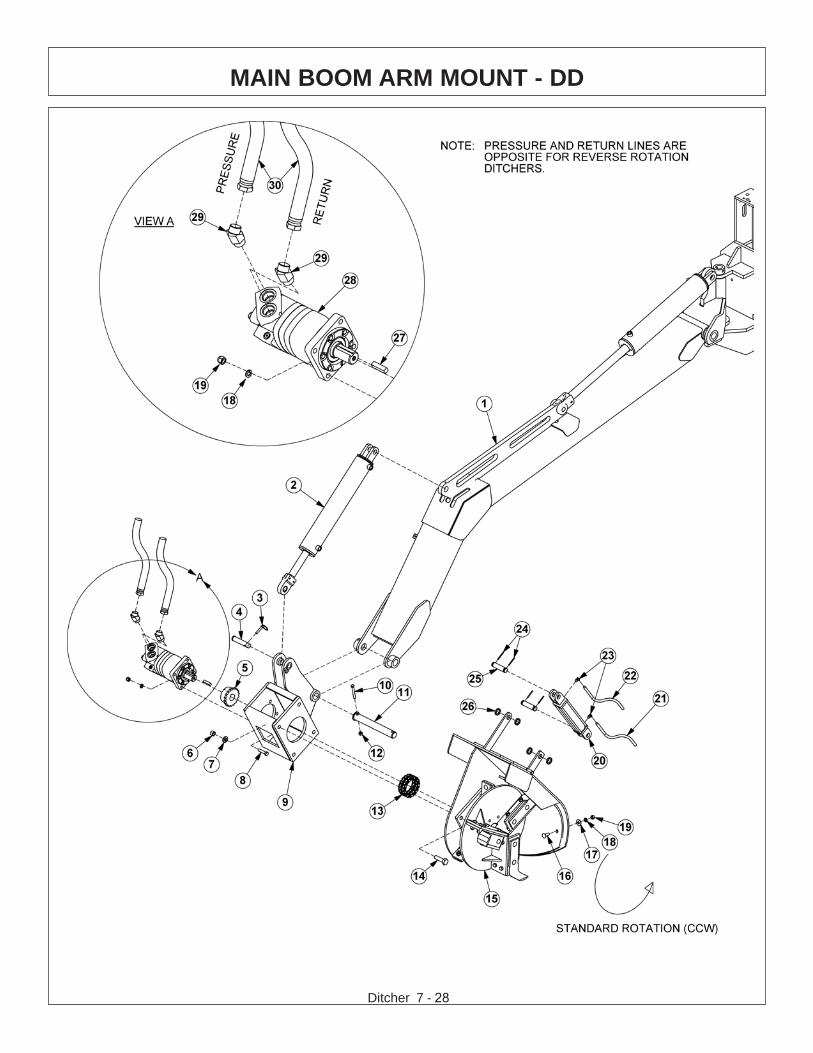
MAIN BOOM ARM MOUNT - DD

Ditcher 7 - 29
MAIN BOOM ARM MOUNT - DD
ITEM PART NO. QTY. DESCRIPTION
1 * REF. MAIN BOOM - REFER TO BOOM ARM ASSY2 * REF. BOOM CYLINDER - REFER TO BOOM ARM ASSY3 TF1143 1 PIN,LYNCH4 TB1036 1 CLEVIS PIN5 6T7005 1 SPROCKET6 21825 4 HEX NUT,3/4,NC7 21993 4 LOCKWASHER,3/4,GR 88 21734 4 CAPSCREW,1/2 x 2-1/4,NC9 22726A 1 BOOM DITCHER MOUNTING HEAD10 21688 1 CAPSCREW,7/16 x 3-1/4,NC11 TB1025D 1 SECONDARY BOOM PIN (DRILLED)12 21677 1 NYLOCK NUT,7/16,NC13 6T7004 1 CHAIN COUPLING14 21835 4 CAPSCREW,3/4 x 2-3/4.NC15 * REF DITCHER HEAD - REFER TO HEAD ASSY16 6T2267 4 CARRIAGE BOLT,1/2 x 1-1/2,NC17 22018 4 FLATWASHER,1/218 21990 8 LOCKWASHER,1/219 21725 8 HEX NUT,1/2,NC20 6T7022 1 CYLINDER,2 x 621 33398 1 HOSE,1/4 x 4822 33403 1 HOSE,1/4 x 6323 32810 2 ELBOW,1/2MOR X 3/8MJ90 ADJ24 TB1023 4 ROLLPIN,7/1625 6T3003D 2 PIN,CLEVIS26 6T7018 4 SPACER27 26142A 1 KEY,1/2 x 1/2 x 228 06504063 1 MOTOR,DITCHER29 33554 2 ELBOW,1MORB x 1MJIC,4530 06500293 2 HOSE,1 x 48

Ditcher 7 - 30
SABER SECONDARY BOOM ARM MOUNT

Ditcher 7 - 31
SABER SECONDARY BOOM ARM MOUNT
ITEM PART NO. QTY. DESCRIPTION
1 * REF. SECONDARY BOOM - REFER TO BOOM ARM ASSY2 * REF. BOOM CYLINDER - REFER TO BOOM ARM ASSY3 32316 1 LINKAGE, BOOM TO CYLINDER,SABER4 32319 2 PIN, LINKAGE, 1-1/2" x 9-13/16"5 21688 3 CAPSCREW, 7/16" x 3-1/4"6 21687 1 CAPSCREW, 7/16" x 3"7 21989 4 LOCKWASHER, 7/16"8 21675 4 HEX NUT, 7/16"9 32313 2 PIN, MOUNT, 1-1/2" x 12-3/8"10 32745 1 LINKAGE W/BUSHINGS, SABER11 32311 1 MOUNT, SWIVEL, HEAD, MOWER12 06500293 2 HOSE, 1" x 48"13 33554 2 ELBOW, 1MOR x 1MJIC, 4514 06504063 1 MOTOR15 21734 1 CAPSCREW, 1/2" x 2-1/4"16 6T7005 1 SPROCKET17 21825 1 HEX NUT, 3/4"18 21993 1 LOCKWASHER, 3/4"19 21990 1 LOCKWASHER, 1/2"20 21725 1 HEX NUT, 1/2"21 06320024 1 MNT, MOTOR, DTCR, SBR22 21835 1 CAPSCREW, 3/4” x 2-3/4”23 6T2408 1 HEX NUT, 5/8"24 21992 1 LOCKWASHER, 5/8"25 25270 1 FLATWASHER,5/8", GR 826 32309 1 PLATE, MOUNT, HEAD, MOWER27 6T2290 1 CAPSCREW, 5/8" x 2" GR 828 6T7004 1 COUPLER CHAIN29 TB1033 2 PIN, CLEVIS30 06537021 4 ROLLPIN,5mm31 32810 2 ELBOW, 1/2" x 3/8"32 33403 1 HOSE, 1/4" x 60"33 33398 1 HOSE, 1/4" x 48"34 6T7022 1 CYLINDER, 2" x 6"35 6T7018 4 SPACER36 * REF. DITCHER HEAD - REFER TO HEAD ASSY

Ditcher 7 - 32
BENGAL SECONDARY BOOM ARM MOUNT

Ditcher 7 - 33
BENGAL SECONDARY BOOM ARM MOUNT
ITEM PART NO. QTY. DESCRIPTION
1 * REF. SECONDARY BOOM, STANDARD2 * REF. BOOM CYLINDER, REFER TO BOOM ARM ASSY3 TF3015 1 PIVOT ASSY4 06520076 1 BEARING,1"ID x 1",CYL,COMP5 TB1033 3 PIN, CLEVIS6 06537021 6 ROLLPIN, 7/32" x 2"7 TF3097 1 PIN, DECK PVT ARM 1" X 9-1/2"8 21635 3 CAPSCREW, 3/8" x 2-1/4",NC9 TF3090 1 PIN, PIVOT ARM, 1" x 4"10 21627 3 NYLOCK NUT, 3/8",NC
TB1028 * PIVOT ARM ASSY11 23421 1 PIVOT ARM12 TB3010 2 BUSHING13 6T3207 2 GREASE ZERK14 06420016 1 PIN, 1-1/2" x 13-1/4", W/ .47" HOLE, NITRIDE15 21688 1 CAPSCREW, 7/16" x 3-1/4",NC16 21677 1 NYLOCK NUT, 7/16" NC17 06420076 1 PIN,1" x 13-1/8", W/ .44" HOLE,NIT18 06500293 2 HOSE, 1" x 48"19 33554 2 ELBOW, 1MOR x 1MJIC, 4520 06504063 1 MOTOR21 21734 4 CAPSCREW, 1/2" x 2-1/4"22 6T7005 1 SPROCKET23 21990 4 LOCKWASHER, 1/2"24 21725 4 HEX NUT, 1/2"25 21825 4 HEX NUT, 3/4"26 21993 4 LOCKWASHER, 3/4"27 6T7004 1 COUPLER CHAIN28 21835 4 CAPSCREW, 3/4" x 2-3/4"29 * REF. DITCHER HEAD30 6T7018 4 SPACER31 06320025 1 MOTOR MOUNT32 33403 1 HOSE, 1/4" x 60"33 33398 1 HOSE, 1/4" x 48"34 6T7022 1 CYLINDER, 2" x 6"35 32810 2 ELBOW, 1/2" x 3/8", 90
Ditcher 7 - 34
BENGAL BRUTE SECONDARY BOOM ARM MOUNT

Ditcher 7 - 35
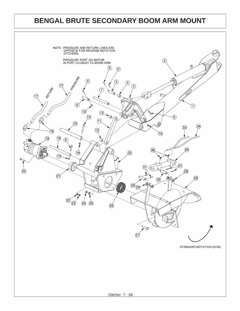
BENGAL BRUTE SECONDARY BOOM ARM MOUNT
ITEM PART NO. QTY. DESCRIPTION
1 * REF. SECONDARY,BOOM,REAR STOW2 * REF. BOOM CYLINDER - REFER TO BOOM ARM ASSY
06700016 * PIVOT ASSY,CPLT3 06310011 1 PIVOT ASSY4 06520076 1 BEARING,1IDx1,CYL,COMP5 06420014 1 PIN,1.00x3.62,W/.22 HOLES,NITRIDE6 TB1023 2 ROLLPIN,7/32" X 2"7 06420019 1 PIN,1.00x9.50,W/.44 HOLE,NITRIDE8 21635 3 CAPSCREW,3/8x2 1/4,NC9 06420020 1 PIN,1.00x4.13,W/.44 HOLE,NITRIDE10 21627 3 NYLOCK NUT,3/8",NC
06700015 * PIVOT ARM ASSY11 06400024 1 PIVOT ARM12 06520076 2 BUSHING13 21688 1 CAPSCREW, 7/16 x 3 1/4,NC14 21677 1 NYLOCK NUT,7/16 NC15 06420016 1 PIN,1.5x13.25,W/.47 HOLE,NITRIDE16 06420076 1 PIN,1.00x13.13,W/.44 HOLE,NIT17 06500385 2 HOSE, 1" x 117"18 33554 2 ELBOW,1MOR x 1MJIC,4519 06504063 1 MOTOR20 21734 4 CAPSCREW, 1/2" x 2-1/4"21 6T7005 1 SPROCKET22 21990 4 LOCKWASHER, 1/2"23 21725 4 HEX NUT, 1/2"24 21825 4 HEX NUT, 3/4"25 21993 4 LOCKWASHER, 3/4"26 6T7004 1 COUPLER CHAIN27 21835 4 CAPSCREW, 3/4" x 2-3/4"28 * REF. DITCHER HEAD - REFER TO HEAD ASSY29 6T7018 4 SPACER30 TB1033 2 PIN,CLEVIS31 06537021 4 ROLLPIN,5mm32 06320025 1 MOTOR MOUNT33 33403 1 HOSE, 1/4" x 60"34 33398 1 HOSE, 1/4" x 48"35 6T7022 1 CYLINDER, 2" x 6"36 32810 2 ELBOW, 1/2 X 3/8"

DITCHER HEAD FORWARD ROTATION
© 2021 Alamo Group Inc.
Ditcher 2-36

Ditcher 7 - 37
DITCH HEAD STANDARD ROTATION
ITEM PART NO. QTY. DESCRIPTION
1 6T7013 1 STANDARD ROTATION HEAD2 6T7020 1 DEFECTOR CHUTE3 6T7008 1 KNIFE MOUNTING DISK4 6T7009 3 KNIFE MOUNTING ANGLE5 6T7011A 3 KNIFE6 6T7012 3 SLINGER TAB7 6T7019 1 DEFLECTOR CHUTE PIN8 22018 6 FLATWASHER 1/2”9 22516 2 COTTER PIN10 6T7015 1 WEAR PLATE11 6T2267 16 CARRIAGE BOLT 1/2” X 1 1/2”12 21990 34 LOCKWASHER 1/2”13 21725 28 HEX NUT 1/2”14 21732 12 CAPSCREW 1/2” X 1 3/4”15 6T2279 6 CAPSCREW 1/2” X 1 1/2”
6T7030 AVAIL DITCHER SPINDLE ASY16 6T7005 1 SPROCKET17 6T1016 1 BEARING LOCK NUT - THICK18 6T1015 1 BEARING LOCK NUT - THIN19 6T1014 1 BEARING ADJUSTMENT SLEEVE20 6T1011 1 UPPER SEAL - SET OF 221 6T1012 2 BEARING CONE22 6T1013 2 BEARING CUP23 6T7007 1 SPINDLE HOUSING24 6T3210 1 GREASE ZERK25 6T1011D 1 LOWER SEAL26 6T1019 1 SPINDLE KEY27 6T1018 1 SPINDLE28 06503064 1 O-RING PLUG,1/8”

DITCHER HEAD REVERSE ROTATION
© 2021 Alamo Group Inc.
Ditcher 2-38

Ditcher 7 - 39
DITCHER HEAD REVERSE ROTATION
ITEM PART NO. QTY. DESCRIPTION
1 6T7014 1 REVERSE ROTATION HEAD2 6T7021 1 DEFECTOR CHUTE3 6T7008R 1 KNIFE MOUNTING DISK4 6T7010 3 KNIFE MOUNTING ANGLE5 6T7011A 3 KNIFE6 6T7012 3 SLINGER TAB7 6T7019 1 DEFLECTOR CHUTE PIN8 22018 6 FLATWASHER 1/2”9 22516 2 COTTER PIN10 6T7015 1 WEAR PLATE11 6T2267 16 CARRIAGE BOLT 1/2” X 1 1/2”12 21990 34 LOCKWASHER 1/2”13 21725 28 HEX NUT 1/2”14 21732 12 CAPSCREW 1/2” X 1 3/4”15 6T2279 6 CAPSCREW 1/2” X 1 1/2”
6T7030 AVAIL DITCHER SPINDLE ASY16 6T7005 1 SPROCKET17 6T1016 1 BEARING LOCK NUT - THICK18 6T1015 1 BEARING LOCK NUT - THIN19 6T1014 1 BEARING ADJUSTMENT SLEEVE20 6T1011 1 UPPER SEAL - SET OF 221 6T1012 2 BEARING CONE22 6T1013 2 BEARING CUP23 6T7007 1 SPINDLE HOUSING24 6T3210 1 GREASE ZERK25 6T1011D 1 LOWER SEAL26 6T1019 1 SPINDLE KEY27 6T1018 1 SPINDLE28 06503064 1 O-RING PLUG,1/8”

Ditcher 7 - 40
3 SP HUSCO - POWER BEYOND COMBO (06502088)

Ditcher 7 - 41
3 SP HUSCO - POWER BEYOND COMBO (06502088)
ITEM PART NO. QTY DESCRIPTION1 TB1017S 1 INLET END COVER2 TB1702 1 END COVER, LOAD SENSE3 TB1017P 1 VALVE SECTION (SINGLE ACTING, SPRING DETENT)4 TB1017N 1 VALVE SECTION (DOUBLE ACTING, CENTER SPRING)5 TB1017N 1 VALVE SECTION (DOUBLE ACTING, CENTER SPRING)
(REMOVE SHUTTLE DISC)6 N/A 1 N/A7 31861 1 RELIEF VALVE, 360 PSI8 28816 1 RELIEF VALVE, 1812 PSI9 TB1017M 1 SHUT OFF PLUG10 TB1017E 1 RELIEF VALVE, 2250 PSI11 31862 1 RELIEF VALVE, 2175 PSI12 31862 1 RELIEF VALVE, 2175 PSI13 28816 1 RELIEF VALVE, 1812 PSI
14 TB1017A 3 VALVE SEAL KIT (FOR ONE SECTION)14A 2 WIPER14B 2 O-RING SMALL14C 1 O-RING LARGE14D 1 SPRING14E 1 PUCKET
15 TB1017L 3 LEVER KIT (FOR ONE SECTION)15A 1 LEVER KNOB15B 1 LEVER15C 2 LEVER WASHER15D 1 LEVER CLIP15E 2 LINKAGE15F 1 LEVER PIN15G 1 ROLL PIN15H 1 LEVER BOOT15J 1 LEVER BOLT15K 1 LEVER DUST COVER15L 1 LEVER NUT
17 23397 1 TIE ROD KIT18 24214 1 O-RING, LARGE

Ditcher 7 - 42
3 SP HUSCO - OPEN CENTER COMBO (06502109)

Ditcher 7 - 43
3 SP HUSCO - OPEN CENTER COMBO (06502109)
ITEM PART NO. QTY DESCRIPTION1 TB1017S 1 INLET END COVER2 TB1701 1 END COVER, LOAD SENSE3 TB1017P 1 VALVE SECTION (SINGLE ACTING, SPRING DETENT)4 TB1017N 1 VALVE SECTION (DOUBLE ACTING, CENTER SPRING)5 TB1017N 1 VALVE SECTION (DOUBLE ACTING, CENTER SPRING)
(REMOVE SHUTTLE DISC)6 N/A 1 N/A7 31861 1 RELIEF VALVE, 360 PSI8 28816 1 RELIEF VALVE, 1812 PSI9 TB1017M 1 SHUT OFF PLUG10 TB1017E 1 RELIEF VALVE, 2250 PSI11 31862 1 RELIEF VALVE, 2175 PSI12 31862 1 RELIEF VALVE, 2175 PSI13 28816 1 RELIEF VALVE, 1812 PSI
14 TB1017A 3 VALVE SEAL KIT (FOR ONE SECTION)14A 2 WIPER14B 2 O-RING SMALL14C 1 O-RING LARGE14D 1 SPRING14E 1 PUCKET
15 TB1017L 3 LEVER KIT (FOR ONE SECTION)15A 1 LEVER KNOB15B 1 LEVER15C 2 LEVER WASHER15D 1 LEVER CLIP15E 2 LINKAGE15F 1 LEVER PIN15G 1 ROLL PIN15H 1 LEVER BOOT15J 1 LEVER BOLT15K 1 LEVER DUST COVER15L 1 LEVER NUT
17 23397 1 TIE ROD KIT18 24214 1 O-RING, LARGE

Ditcher 7 - 44
GEAR REDUCER

Ditcher 7 - 45
ITEM PART NO. QTY. DESCRIPTION
1 33682 1 OUTPUT SHAFT OR SPINDLE2 32834 1 SEAL3 33684 1 BEARING CONE4 33685 1 BEARING CUP5 * 6 CAPSCREW6 * 6 FLATWASHER7 * 1 PIPE PLUG8 34330 1 HUB9 06504114 1 BEARING CONE, #610 34327 1 RETAINING RING11 * 1 RING GEAR12 34328 1 CARRIER ASSEMBLY13 * 1 SUN GEAR14 34329 1 THRUST WASHER15 * 1 COVER16 * 1 MAGNETIC PLUG17 * 1 CAPSCREW18 * 1 PIPE PLUG19 06504115 1 BEARING CUP, #6
GEAR REDUCER

Ditcher 7 - 46
MOTOR BREAKDOWN - 06504014

Ditcher 7 - 47
MOTOR BREAKDOWN - 06504014
ITEM PART NO. QTY. DESCRIPTION
06504014 * MOTOR1 22790 1 HOUSING, SEC2 06504088 1 HOUSING, SEC3 06504094 1 HOUSING, GEAR4 06504107 1 SET, GEAR SHAFT5 06504108 4 CAPSCREW6 06504078 2 SCREW, DRIVE7 06504093 4 PIN, DOWEL8 06504077 1 NAME PLATE9 06504095 2 THRPL10 02961940 1 PLUG, ODT11 6T5200 1 RING, SNAP12 06504096 1 O-RING13 6T5101 1 SEAL, LIP14 06504097 1 SEAL, LIP15 22797 2 SEAL, SQ-R16 06504098 4 SEAL, SIDE CHAN17 06504099 4 SEAL, END CHAN18 06504100 2 SEAL, BK-UP19 06504101 1 RTNR, SEAL20 6T5809 2 CHECK ASSY21 06504102 4 WASHER* 06504103 AVAIL. SEAL KIT

Ditcher 7 - 48
MOTOR BREAKDOWN - 06504063

Ditcher 7 - 49
MOTOR BREAKDOWN - 06504063
ITEM PART NO. QTY. DESCRIPTION
1 06501580 1 SHAFT AND BEARING KIT1a 06501581 1 KEY2 06501582 1 HOUSING,BEARING3 06501583 1 RETAINER,FRONT4 06501584 6 SCREW,CAP5 06501585 1 DRIVE,MAIN6 N/A 1 GEROLER®7 N/A 1 PLATE,VALVE8 N/A 1 DRIVE,VALVE9 N/A 1 VALVE10 N/A 1 SEAL,FACE,OUTER11 N/A 1 SEAL,FACE,INNER12 N/A 3 SPRING,COMPRESSION13 N/A 1 BALANCE RING W/ PINS14 N/A 1 HOUSING,VALVE15 N/A 1 SEAL16 N/A 2 SEAL17 06501586 2 SEAL18 06501587 1 DUST SEAL19 06501588 1 SEAL,SHAFT20 06501589 1 SEAL,SHAFT,FACE21 N/A 2 SCREW,CAP22 N/A 2 SCREW,CAP26 06501590 1 SEAL27 N/A 1 SEAL29 N/A 2 BALL,STEEL34 06501591 1 RING,BACK-UP41a 06501598 1 PLUG ASSY51 N/A 2 CHECK PLUG ASSY52 N/A 2 SPRING,COMPRESSION* 24063 AVAIL SEAL KIT,SHAFT (INCLUDES ITEMS 17,18,19,20 & 34)

DITCHER MOUNTING
© 2018 Alamo Group Inc.
DIT
CH
ER
Ditcher 7-50
REPLACING DITCHER MOTORRemove the ditcher from the tractor. Turn the
ditcher unit on its side, and rest it on a flat surface, with the motor side on top. Remove the old motor and the bolts connecting the boom arm to the ditcher unit. Remove the chains from the sprockets. Put the new motor in position and loosely replace the bolts for the motor and the boom arm. DO NOT tighten at this time.
Line up the sprockets that will be carrying the chains. When the sprockets are lined up correctly, clamp them together with 3 or 4 vise grips to maintain their position. Tighten the bolts on the ditcher and motor and remove the vise grips. Move the motor side sprocket over approximately 3/8” to make room for the movement of the chains. The sprocket on the spindle side is in place and should NOT be moved. Replace the chains. Reconnect the ditcher to the tractor.

WARRANTYSECTION
Warranty Section 8-1

.

WARRANTY INFORMATION
Tiger Corporation, 3301 N. Louise, Sioux Falls, South Dakota, warrants to theoriginal Retail Customer, the new Tiger equipment is free of defects in material andworkmanship. Any part of equipment that in Tiger’s judgement, show evidence ofsuch defects will be repaired or replaced without charge, provided that the failure ofpart(s) shall have occurred within twelve (12) months from the date of delivery ofsaid equipment to the Retail Customer. Expendable components such as knives,oil, chain sprockets, skid shoes, knife mounting disks and the like are excluded butnot limited to this warranty.
The Retail Customer must pay the transportation cost to and from the TigerDealer’s service shop for warranty service. Warranty service will be performed bythe Tiger Dealer from whom the equipment was purchased, during service shopregularly scheduled days and hours of operation.
All Tiger obligation under this warranty shall be terminated if the equipment ismodified or altered in ways not approved in writing by Tiger, if repair parts other thangenuine Tiger repair parts have been used, or if the equipment has been subject tomisuse, neglect, accident, improper maintenance or improper operation.
Tiger Corporation reserves the right to make improvements in design orchanges in specification at any time without incurring any obligation to owners ofequipment previously sold.
No agent or person has authority to alter, add to or waive the above warrantieswhich are agreed to be in the only warranties, representations or promises,expressed or implied, as to the quality or performance of the products covered andwhich do not include any implied warranty of merchantability or fitness. In no eventwill Tiger be liable for incidental or consequential damages or injuries, including, butnot limited to, loss of profits, rental or substitute equipment or other commercialloss.
THERE ARE NO WARRANTIES WHICH EXTENDBEYOND THOSE EXPRESSED HEREIN.
It is the Purchasers obligation to sign the warranty registration form AFTER he /she has Read and Understands the Operation and Safety Instructions statedwithin this manual.

ONE LAST WORDThis manual cannot possibly cover all of the
potentially hazardous situations you willencounter. By being familiar with the
safety rules, operating and maintenanceinstructions in this manual you can help preventaccidents. The objective of this manual is to
help make you a better operator. Remember,SAFETY IS YOU!
Your safety and the safety of those around youdepends on YOU. Common sense should
play a large role in the operation of this machine.
Since we at Tiger Corporation are constantly striving to improve out products, wereserve the right to change specifications or design at any time.

TO THE OWNER / OPERATOR / DEALER
To keep your implement running efficiently and safely, read your manual thoroughly and followthese directions and the Safety Messages in this manual and on the machine. The table ofcontents clearly identifies each section where you can easily find the information you need.
The Occupational Safety and Health Act (OSHA 1928.51 subpart C) makes the followingminimum requirements for tractor operators.
OWNER REQUIREMENTS:
1. Provide a Roll-Over-Protective Structure that meets the requirements of this Standard; and2. Provide Seatbelts that meet the requirements of this Standard and SAE J3C; and3. Ensure that each employee uses such Seatbelt while the tractor is moving; and4. Ensure that each employee tightens the Seatbelt sufficiently to confine the employee to the
protected area provided by the ROPS.
OPERATOR REQUIREMENTS:
1. Securely fasten seatbelt it the tractor has a ROPS.2. Where possible, avoid operating the tractor near steep ditches, embankments, and holes.3. Reduce speed when turning, crossing slopes, and on rough, slick, or muddy surfaces.4. Stay off slopes too steep for safe operation.5. Watch where you are going – especially at row ends, on roads, and around trees.6. Do Not permit others to ride.7. Operate the tractor smoothly – no jerky turns, starts, or stops.8. Hitch only to the draw-bar and hitch points recommended by the tractor manufacturer.9. When the tractor is stopped, set brakes securely and use park lock, if available

Printed in USA© Tiger Corporation