diversified products, inc. - cisco-eagle · diversified products, inc. best/flex power expandable...
TRANSCRIPT

Best Diversified Products, Inc.107 Flint St.
Jonesboro, Arkansas 72401Phone: 870-935-0970
Toll Free: 800-327-9209Fax: 870-935-3661
99042July, 2003
Please read entire manual before operating conveyor.
Factory Order Number:_______________
Serial Number:______________________
Ship Date:__________________________
Manual
Diversified Products, Inc.Best/Flex Power Expandable Conveyor
With AccumulationLeg Mount Accumulation
Read-Between-Roller Accumulation
E230497

2
Contents
General Operation 4
Host System Interface 4
Installation 5
Safety Information (UL Compliance Statement) 6
Maintenance Schedule 7
Accumulation Trouble Shooting Guide 8-10
Circuit Component Layout 11
Leg Mounted Photo-Sensors
Input Zone Layout and Parts List 12-13
Middle Zone Layout and Parts List 14-15
Last Zone Layout and Parts List 16-17
Read-Between-Roller Mounted Photo-Sensors
Input Zone Layout and Parts List 18-19
Middle Zone Layout and Parts List 20-21
Last Zone Layout and Parts List 22-23
Power Supply Connection Diagram 26
Zone Connection Diagram 27
Interface Connection Diagram 28
Control Assembly 29
Note 30-31

3
Thank YouCongratulations on your purchase of the BEST/FLEX POWER CONVEYOR with ACCUMU-LATION. This conveyor has been designed to increase your material handling productivity whilepreventing damage to your packages through zero pressure accumulation. Please take the time toread through this manual and familiarize yourself with your new conveyor and its handling, mainte-nance and safety procedures.
4
General Operation
The BEST/FLEX POWER CONVEYOR is a flexible, expandable powered conveyor thatoperates from a standard 115VAC grounded outlet.
The accumulation option allows zero pressure accumulation of packages in individual zonesalong the conveyor. Packages are detected by photoelectric sensors located at the end of each zone.When no packages are on the conveyor, all zones will run. The first package placed on the conveyorwill travel to the last zone on the discharge end of the conveyor and stop when it breaks that zone’sphotoeye beam. The remaining zones continue to run. The next package placed on the conveyorwill stop at the next-to-last zone. Packages will continue to accumulate the length of the conveyor.This allows full utilization of the conveyor without letting packages become damaged from overcrowding or “bunching up” on the conveyor.
When the package in the discharge end zone is removed from the conveyor, all zones willstart and the packages will again “accumulate” toward the discharge end of the conveyor.
The accumulation conveyor comes with photoelectric sensors set in two configurations. Notethat the configuration is customer-determined at the time of the order.
One configuration is with the photo-eyes mounted on the leg above and outside the conveyorbed. This configuration is known as Leg Mount Optics.
The second configuration is with the photo-eyes mounted slightly below and in the conveyorbed, at the leg locations. This configuration is known as Read Between Roller Optics.
Host System Interface:Two sets of dry contacts, one normally open and one normally closed, are provided to give aninterface signal from the BEST/FLEX conveyor to a host control system. The normally open con-tacts will be closed anytime one or more zones of the BEST/FLEX Accumulation conveyor arerunning. A terminal block for these contacts is provided on the power supply board located in thelarger enclosure at the end of the conveyor. (Refer to the POWER SUPPLY CONNECTION DIA-GRAM.) This terminal block is labeled “EXTRA CONTACTS”. The individual terminals arelabeled “NO” (normally open), “COM” (common), “NC” (normally closed) and “GRD” (ground).These contacts are rated up to 10A/250VAC or 10A/30VDC.
CAUTION: Always unplug the 115VAC power cord before working on the unit or opening anyelectrical enclosures. Never operate the conveyor with the enclosures open.

5
Installation1) Unpack the BEST/FLEX POWER CONVEYOR and inspect for damage incurred in shipping.
Pay particular attention to the wiring to ensure no wires are pulled loose or damaged in any way.If damage is found, contact the factory before applying power to the conveyor.
2) Make sure all START/STOP switches (there will be one switch at each end of the conveyor) arein the STOP position.
3) Roll unit into position. If applicable, use the connect hooks to attach the BEST/FLEX to a rigidconveyor.
4) Plug the power cord into a 115VAC grounded receptacle.
5) Release all Emergency Stop pushbuttons. (Any one Emergency Stop pushbutton that is depressed willprevent the conveyor from running.) There is an on/off switch on the control box located near themiddle of the conveyor.
6) Adjust the speed of the conveyor with the potentiometer on the side of the enclosure mountednear the power cord.
7) Begin placing packages on the conveyor. They will travel to the last available zone and stopuntil packages are removed from the discharge end.

6
Safety Information1) Avoid wearing excessively loose clothing when working with moving machinery.
2) Keep long hair pulled up to prevent it from becoming caught in moving parts.
3) Move conveyor only by grasping the handles. Keep hands, clothing and other itemsaway from sidebars while moving conveyor.
4) BEST/FLEX conveyors and their electrical systems must only be serviced by properlytrained and qualified technicians.
5) Conveyor’s power cord must be connected to a grounded receptacle that is protected byan over current device rated at no larger than 15 Amps unless otherwise specified.
6) Never service conveyor with power applied. Always disconnect power cord beforeservicing equipment.
7) Never operate conveyor with any electrical enclosure open.
Underwriter’s Laboratories Certification Statement
Best conveyors have been thoroughly tested by Underwriter’s Laboratories, and have been found to meet their strict standards for Factory Automation Equipment. Our conveyors are certified to UL508 Standards when shipped from our plant. Our UL file number is E230497. All standards can be found on-line at www.ul.com. ANY MODIFICATION FROM ORIGIONAL FACTORY CONDITION OR REPAIRS NOT PERFORMED BY BEST DIVERSIFIED PRODUCTS’ TECHNITIONS OR CERTIFIED CONTRACTORS MAY VOID UL CERTIFICATION. For specific assistance regarding any UL issues, please contact your Best Diversified Products, Inc. sales representative at 1-800-327-9209.

7
Maintenance ScheduleThe BEST/FLEX Power Conveyor is virtually maintenance free. However, we do recommend thefollowing:
1) Keep the conveyor clean and free of debris, dirt and grease accumulation.
2) Periodically lubricate all slotted components with a lightweight lubricant toensure smooth and easy operation.
3) Inspect wires and cables for damage. If damage to wires or cables is found,disconnect the power cord immediately and do not operate unit until properrepairs are made.
4) Inspect belts for wear. Replace excessively worn belts.
5) Inspect side bar nuts and bolts for looseness or missing parts. Tighten or replaceas needed.
6) Make sure reflectors and photoeyes are clean, unobstructed and properly aligned.
7) Verify START/E-STOP/STOP switches operate properly.
All of the above maintenance inspections should be conducted daily.
8
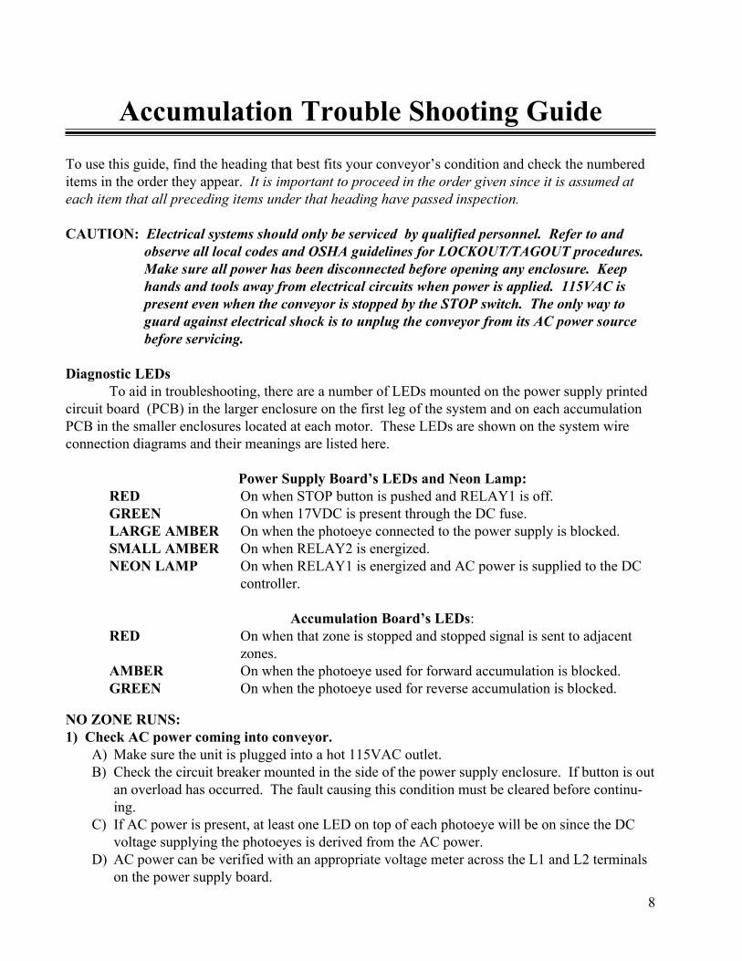
Accumulation Trouble Shooting GuideTo use this guide, find the heading that best fits your conveyor’s condition and check the numbereditems in the order they appear. It is important to proceed in the order given since it is assumed ateach item that all preceding items under that heading have passed inspection.
CAUTION: Electrical systems should only be serviced by qualified personnel. Refer to andobserve all local codes and OSHA guidelines for LOCKOUT/TAGOUT procedures.Make sure all power has been disconnected before opening any enclosure. Keephands and tools away from electrical circuits when power is applied. 115VAC ispresent even when the conveyor is stopped by the STOP switch. The only way toguard against electrical shock is to unplug the conveyor from its AC power sourcebefore servicing.
Diagnostic LEDsTo aid in troubleshooting, there are a number of LEDs mounted on the power supply printed
circuit board (PCB) in the larger enclosure on the first leg of the system and on each accumulationPCB in the smaller enclosures located at each motor. These LEDs are shown on the system wireconnection diagrams and their meanings are listed here.
Power Supply Board’s LEDs and Neon Lamp:RED On when STOP button is pushed and RELAY1 is off.GREEN On when 17VDC is present through the DC fuse.LARGE AMBER On when the photoeye connected to the power supply is blocked.SMALL AMBER On when RELAY2 is energized.NEON LAMP On when RELAY1 is energized and AC power is supplied to the DC
controller.
Accumulation Board’s LEDs:RED On when that zone is stopped and stopped signal is sent to adjacent
zones.AMBER On when the photoeye used for forward accumulation is blocked.GREEN On when the photoeye used for reverse accumulation is blocked.
NO ZONE RUNS:1) Check AC power coming into conveyor.
A) Make sure the unit is plugged into a hot 115VAC outlet.B) Check the circuit breaker mounted in the side of the power supply enclosure. If button is out
an overload has occurred. The fault causing this condition must be cleared before continu-ing.
C) If AC power is present, at least one LED on top of each photoeye will be on since the DCvoltage supplying the photoeyes is derived from the AC power.
D) AC power can be verified with an appropriate voltage meter across the L1 and L2 terminalson the power supply board.
9
Accumulation Trouble Shooting Guide (Cont.)
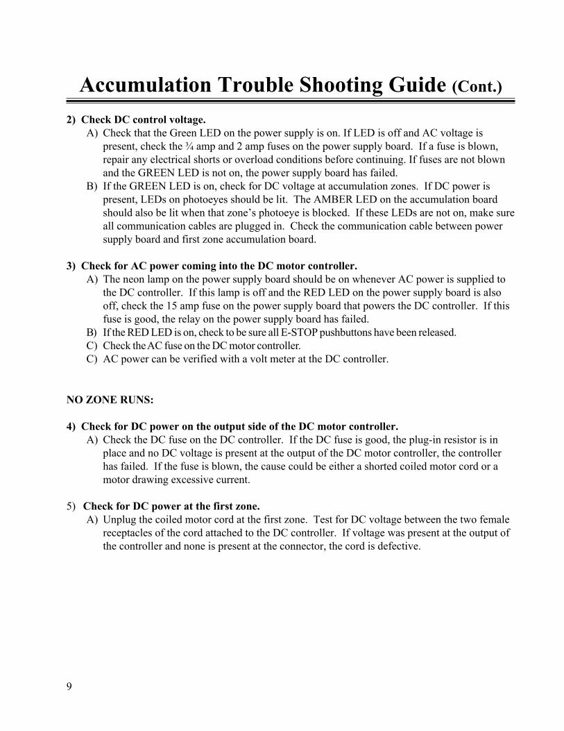
2) Check DC control voltage.A) Check that the Green LED on the power supply is on. If LED is off and AC voltage is
present, check the ¾ amp and 2 amp fuses on the power supply board. If a fuse is blown,repair any electrical shorts or overload conditions before continuing. If fuses are not blownand the GREEN LED is not on, the power supply board has failed.
B) If the GREEN LED is on, check for DC voltage at accumulation zones. If DC power ispresent, LEDs on photoeyes should be lit. The AMBER LED on the accumulation boardshould also be lit when that zone’s photoeye is blocked. If these LEDs are not on, make sureall communication cables are plugged in. Check the communication cable between powersupply board and first zone accumulation board.
3) Check for AC power coming into the DC motor controller.A) The neon lamp on the power supply board should be on whenever AC power is supplied to
the DC controller. If this lamp is off and the RED LED on the power supply board is alsooff, check the 15 amp fuse on the power supply board that powers the DC controller. If thisfuse is good, the relay on the power supply board has failed.
B) If the RED LED is on, check to be sure all E-STOP pushbuttons have been released.C) Check the AC fuse on the DC motor controller.C) AC power can be verified with a volt meter at the DC controller.
NO ZONE RUNS:
4) Check for DC power on the output side of the DC motor controller.A) Check the DC fuse on the DC controller. If the DC fuse is good, the plug-in resistor is in
place and no DC voltage is present at the output of the DC motor controller, the controllerhas failed. If the fuse is blown, the cause could be either a shorted coiled motor cord or amotor drawing excessive current.
5) Check for DC power at the first zone.A) Unplug the coiled motor cord at the first zone. Test for DC voltage between the two female
receptacles of the cord attached to the DC controller. If voltage was present at the output ofthe controller and none is present at the connector, the cord is defective.
10
Accumulation Trouble Shooting Guide (Cont.)
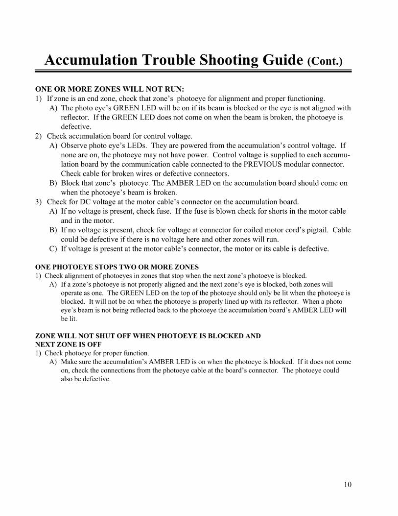
ONE OR MORE ZONES WILL NOT RUN:1) If zone is an end zone, check that zone’s photoeye for alignment and proper functioning.
A) The photo eye’s GREEN LED will be on if its beam is blocked or the eye is not aligned withreflector. If the GREEN LED does not come on when the beam is broken, the photoeye isdefective.
2) Check accumulation board for control voltage.A) Observe photo eye’s LEDs. They are powered from the accumulation’s control voltage. If
none are on, the photoeye may not have power. Control voltage is supplied to each accumu-lation board by the communication cable connected to the PREVIOUS modular connector.Check cable for broken wires or defective connectors.
B) Block that zone’s photoeye. The AMBER LED on the accumulation board should come onwhen the photoeye’s beam is broken.
3) Check for DC voltage at the motor cable’s connector on the accumulation board.A) If no voltage is present, check fuse. If the fuse is blown check for shorts in the motor cable
and in the motor.B) If no voltage is present, check for voltage at connector for coiled motor cord’s pigtail. Cable
could be defective if there is no voltage here and other zones will run.C) If voltage is present at the motor cable’s connector, the motor or its cable is defective.
ONE PHOTOEYE STOPS TWO OR MORE ZONES1) Check alignment of photoeyes in zones that stop when the next zone’s photoeye is blocked.
A) If a zone’s photoeye is not properly aligned and the next zone’s eye is blocked, both zones willoperate as one. The GREEN LED on the top of the photoeye should only be lit when the photoeye isblocked. It will not be on when the photoeye is properly lined up with its reflector. When a photoeye’s beam is not being reflected back to the photoeye the accumulation board’s AMBER LED willbe lit.
ZONE WILL NOT SHUT OFF WHEN PHOTOEYE IS BLOCKED ANDNEXT ZONE IS OFF1) Check photoeye for proper function.
A) Make sure the accumulation’s AMBER LED is on when the photoeye is blocked. If it does not comeon, check the connections from the photoeye cable at the board’s connector. The photoeye couldalso be defective.
11
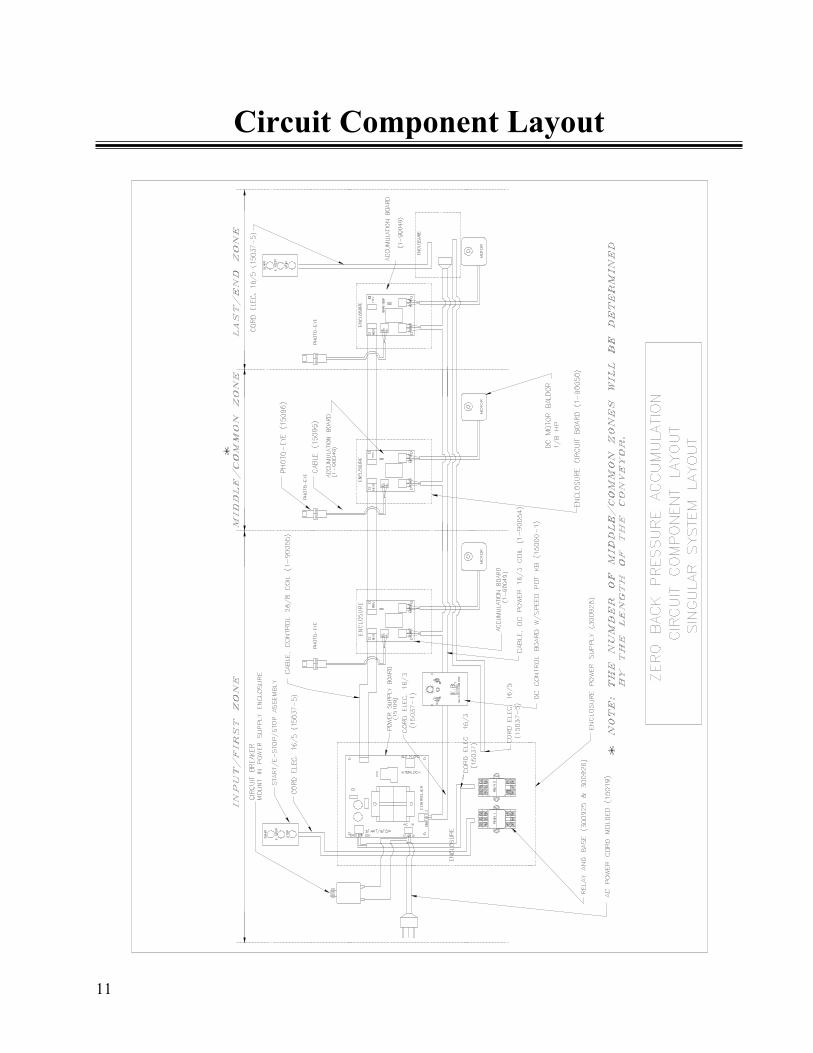
Circuit Component Layout
12
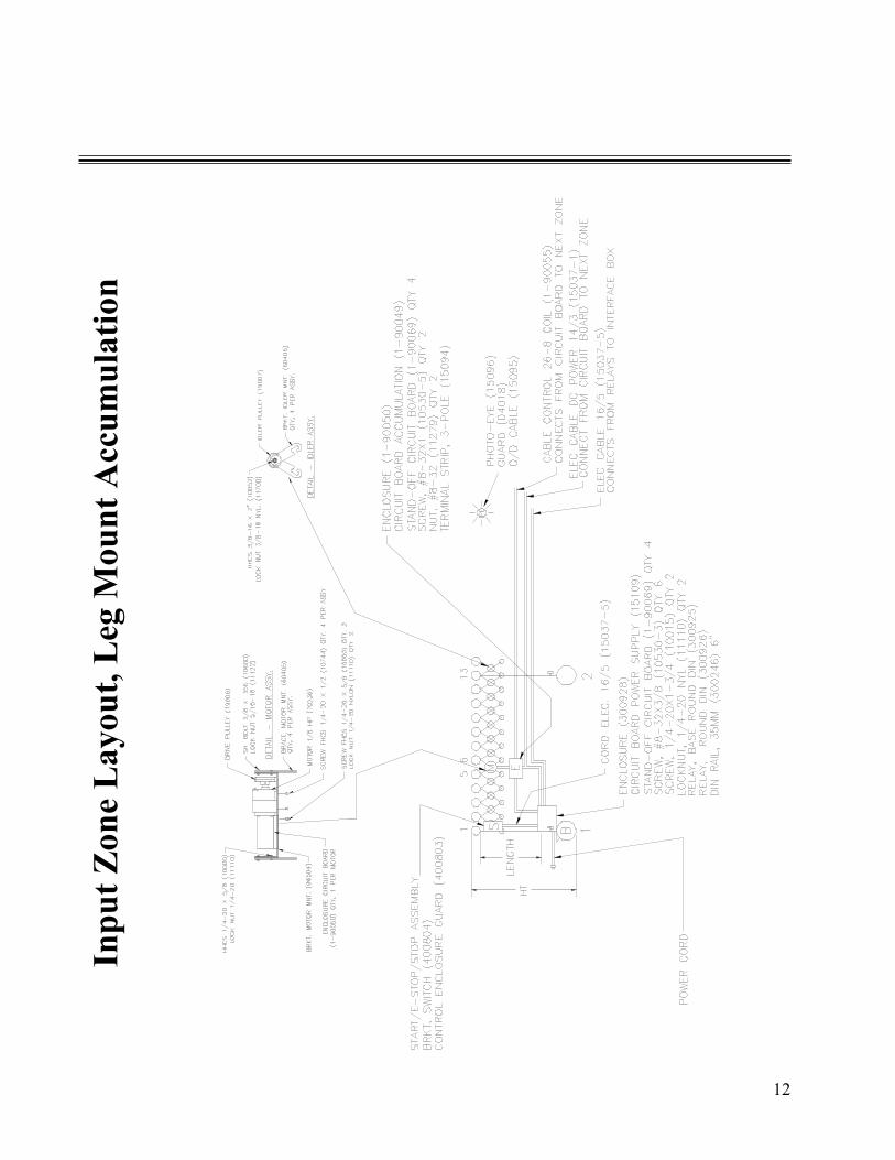
Inpu
t Zon
e La
yout
, Leg
Mou
nt A
ccum
ulat
ion

13
Inpu
t Zon
e Pa
rts L
ist, L
eg M
ount
Acc
umul
atio
n1-
9004
91
CIR
CU
IT B
OA
RD
2-W
AY
AC
CUM
1111
1A
S R
EQ
DL
OCK
NU
T N
YL
5/1
615
109
1C
IRC
UIT
BO
AR
D P
0WE
R S
UPP
1218
5A
S R
EQ
DSP
AC
ER
3/4
OD
X 1
3/32
ID
X 0
.20
1-90
056
4ST
AN
D O
FF P
LA
STIC
1218
7A
S R
EQ
DW
ASH
ER N
YL
1"
OD
1-90
069
4SP
AC
ER
1/4
HE
X X
3/4
LG
6008
1-P
RA
S R
EQ
DL
EG
MN
T B
RK
T, 5
" or
1503
7-1
6 FT
CO
RD
EL
EC
14/3
SJ 3
00V
6037
9-P
RA
S R
EQ
DL
EG
MN
T B
RK
T, 4
" or
1-90
055
1C
ABL
E C
ON
TR
OL
26/
860
375
AS
RE
QD
LEG
MN
T B
RK
T, 3
-1/2
" or
1-90
050
1E
NCL
OSU
RE
ASS
Y C
IRC
BO
AR
D60
295-
PR
AS
RE
QD
LEG
MN
T B
RK
T, 3
"30
0928
1E
NC
LOSU
RE P
OW
ER
SU
PPL
Y60
463-
5A
S R
EQ
DR
OL
LE
R M
NT
BRK
T, 5
" or
1500
0-1
1C
ON
TRO
L B
OA
RD
W/S
PEE
D P
OT
6046
3-4
AS
RE
QD
RO
LL
ER
MN
T B
RKT
, 4"
or60
463-
35A
S R
EQ
DRO
LLE
R M
NT
BR
KT
, 3-1
/2"
or1-
9006
71
CIR
CU
IT B
RE
AK
ER
, 15
AM
P S
ER
VICE
or
6046
3-3
AS
RE
QD
RO
LL
ER M
NT
BR
KT
, 3"
1-90
076
1C
IRC
UIT
BR
EA
KE
R, 2
0 A
MP
SE
RVI
CE o
r50
098-
ZZ
AS
RE
QD
RO
LL
ER 1
.5 x
ZZ
(ZZ
=18,
24, o
r 30
) or
1-90
068
1C
IRC
UIT
BR
EA
KE
R, 3
0 A
MP
SERV
ICE
5009
9-Z
ZA
S R
EQ
DRO
LLE
R 1
.9 x
ZZ
(Z
Z=18
,24,
or 3
0)10
530-
24
RH
MS
#10-
24 X
3/4
9503
7-Z
ZA
S R
EQ
DA
XL
E 12
MM
x Z
Z L
EN
GT
H, 5
/16
TH
D11
999
4W
ASH
ER
FL
AT
3/1
610
024
AS
RE
QD
SCR
EW, H
HC
5/16
-18
X 1
/212
120
4W
ASH
ER L
OC
K 3
/16
7023
61
MO
TO
R, D
C 1
/8 H
P (
0-16
0 FP
M)
or11
279-
14
NU
T H
EX #
10-3
270
236-
31
MO
TO
R, D
C 1
/8 H
P (
0-20
0 FP
M)
1509
61
PH
OT
O-E
YE
SEN
SOR
AB
NP
N96
504
1B
RK
T M
OT
OR
MN
T15
095
1C
ABL
E Q
/D B
RA
D H
AR
RISO
N60
405
4BR
AC
E M
OT
OR
MN
T1-
9002
72
REFL
ECT
OR
1074
44
SCR
EW
, 1/4
-20
X 5
/8 H
HC
4018
2P
HO
TO
EY
E M
T B
RK
T W
/GU
ARD
1000
02
SCR
EW
HH
C 1/
4-20
X5/
860
900
2B
RK
T P
HO
TO
-EY
E M
T A
B11
110
2L
OC
KN
UT
1/4
-20
NY
LON
1-90
019
3ST
RA
IN R
ELI
EF .2
50 C
AB
LE
1005
26
SCR
EW
, 3/8
-16
X 2
HH
C12
000
4W
ASH
ER
FL
AT
1/4
"11
130
6L
OC
KN
UT
, 3/8
-16
NY
LO
N11
110
6LO
CK
NU
T N
YL
1/4
1900
61
PU
LLE
Y D
RIV
E D
BL
GR
OO
VE
1900
7A
S R
EQ
DP
UL
LEY
IDL
ER
DB
L G
RO
OV
E15
037-
113
FTEL
EC
CO
RD
18/
260
406
AS
RE
QD
IDL
ER
MN
T B
RK
T15
019
1P
LU
G/C
OR
D M
12/
3 30
0V 3
' or
1246
62
DR
IVE
BE
LT
1502
4-30
1M
AL
E P
WR
PLU
G 3
0 A
MP
plu
s12
467
AS
RE
QD
IDLE
R B
EL
T15
037-
73
FTEL
EC
CO
RD
10/
31-
9004
9-S
1A
CCU
MU
LA
TIO
N S
CH
EM
AT
IC1-
9007
01
STR
AIN
RE
LIE
F 7P
210
015
2SC
RE
W H
HC
1/4-
20X
1 3/
41-
9007
13
STR
AIN
REL
IEF
#MP
30-1
1053
44
SCR
EW
HH
C 1
/4-2
0X 1
/2"
1-90
072
2ST
RA
IN R
ELI
EF
MP
4K1
1502
525
CA
BLE
TIE
7 3
/8L
, 3/1
6W15
012-
13
STR
AIN
RE
LIE
F 16
/3 W
IRE
1503
0-3
8SC
RE
W #
8-32
X3/
8 R
HM
1501
57
TE
RM
FO
RK
#10S
TU
D 1
6-14
GA
B15
045-
151
FUSE
15A
MP
250
VO
LT
CE
RMIC
6049
2A
S R
EQD
SID
EBA
R, B
FP15
or
1509
74
1/2"
CA
BLE
CL
AM
P H
AN
GER
6050
7A
S R
EQD
SID
EB
AR,
BFP
1915
098
8N
YL
ON
AX
LE
CLA
MP
1060
0A
S R
EQD
SID
EB
AR
BO
LT
, 3/8
X 3
/8, 5
/16
TH
D15
109-
S1
PO
WE
R SU
PPL
Y S
CH
EM
AT
IC10
620
AS
REQ
DSI
DE
BAR
BO
LT
, 3/8
X 0
.70,
5/1
6 T
HD
6044
01
STRA
P, E
NC
LO
SUR
E SU
PPO
RT10
624
AS
REQ
DSI
DE
BAR
BO
LT
, 3/8
X 1
.10,
5/1
6 T
HD
1503
0-5
2SC
RE
W, #
8-32
X 1
1509
41
TE
RM
ST
RIP
, 3-P
OL
E11
279
2N
UT
, #8-
32

14
Mid
dle
Zone
Lay
out,
Leg
Mou
nt A
ccum
ulat
ion

15
Mid
dle
Zone
Par
ts L
ist, L
eg M
ount
Acc
umul
atio
n
1-90
049
1C
IRC
UIT
BO
AR
D 2
-WA
Y A
CC
UM
1509
41
TER
M S
TRIP
, 3-P
OLE
1-90
056
4ST
AN
D O
FF P
LAST
IC60
463-
5A
S R
E QD
RO
LLER
MN
T B
RK
T, 5
" or
1503
7-1
6 FT
CO
RD
ELE
C 1
4/3
SJ 3
00V
6046
3-4
AS
RE Q
DR
OLL
ER M
NT
BR
KT,
4" o
r1-
9005
51
CA
BLE
CO
NTR
OL
26/8
6046
3-35
AS
RE Q
DR
OLL
ER M
NT
BR
KT,
3-1
/2" o
r1-
9005
01
ENC
LOSU
RE
ASS
Y C
IRC
BO
AR
D60
463-
3A
S R
E QD
RO
LLER
MN
T B
RK
T, 3
"1-
9008
11
ENC
LOSU
RE
CO
VE R
5009
8-ZZ
AS
REQ
DR
OLL
ER 1
.5 x
ZZ
(ZZ=
18,2
4, o
r 30)
or
1-90
152
1TH
UM
B S
CR
EW, #
8-32
5009
9-ZZ
AS
REQ
DR
OLL
ER 1
.9 x
ZZ
(ZZ=
18,2
4, o
r 30)
1-90
153
1N
UT ,
U-C
LIP,
#8-
3295
037-
ZZA
S R
EQD
AX
LE 1
2 M
M x
ZZ
LEN
GTH
, 5/1
6 TH
D15
096
1PH
OTO
-EY
E SE
NSO
R A
B N
PN10
024
AS
RE Q
DSC
REW
, HH
C 5
/16-
18 X
1/2
1509
51
CA
BLE
Q/D
BR
AD
HA
RR
ISO
N70
236
1M
OTO
R, D
C 1
/8 H
P (0
-160
FPM
) or
1-90
027
2R
EFLE
CTO
R70
236-
31
MO
TOR
, DC
1/8
HP
(0-2
00 F
PM)
4018
2PH
OTO
EYE
MT
BR
KT
W/G
UA
RD
9650
41
BR
KT
MO
TOR
MN
T60
900
2B
RK
T PH
OTO
-EY
E M
T A
B60
405
4B
RA
CE
MO
TOR
MN
T12
000
2W
ASH
ER F
LAT
1/4"
1074
44
SCR
EW, 1
/4-2
0 X
5/8
HH
C11
110
2LO
CK
NU
T N
YL
¼10
000
2SC
REW
HH
C 1
/4-2
0X5/
81-
9007
01
STR
AIN
REL
IEF
7P2
1111
02
LOC
KN
UT
1/4-
20 N
YLO
N1-
9007
13
STR
AIN
REL
IEF
#MP3
0-1
1005
26
SCR
EW, 3
/8-1
6 X
2 H
HC
1-90
072
2ST
RA
IN R
ELIE
F M
P4K
111
130
6LO
CK
NU
T, 3
/8-1
6 N
YLO
N15
012-
13
STR
AIN
REL
IEF
16/3
WIR
E19
006
1PU
LLEY
DR
IVE
DB
L G
RO
OV
E15
015
7TE
RM
FO
RK
#10S
TUD
16-
14G
AB
1900
7A
S R
EQD
PULL
EY ID
LER
DB
L G
RO
OV
E60
492
AS
REQ
DSI
DEB
AR
, BFP
15 o
r60
406
AS
REQ
DID
LER
MN
T B
RK
T
6050
7A
S R
EQD
SID
EBA
R, B
FP19
1246
62
DR
IVE
BEL
T10
600
AS
REQ
DSI
DEB
AR
BO
LT, 3
/8 X
3/8
, 5/1
6 TH
D12
467
AS
REQ
DID
LER
BEL
T10
620
AS
REQ
DSI
DEB
AR
BO
LT, 3
/8 X
0.7
0, 5
/16
THD
1-90
049-
S1
AC
CU
MU
LATI
ON
SC
HEM
ATI
C10
624
AS
REQ
DSI
DEB
AR
BO
LT, 3
/8 X
1.1
0, 5
/16
THD
1001
52
SCR
EW H
HC
1/4
-20X
1 3/
4
1111
1A
S R
EQD
LOC
KN
UT
NY
L 5/
1610
534
4SC
REW
HH
C 1
/4-2
0X 1
/2"
1218
5A
S R
EQD
SPA
CER
3/4
OD
X 1
3/32
ID X
0.2
015
025
25C
AB
LE T
IE 7
3/8
L, 3
/16W
1218
7A
S R
EQD
WA
SHER
NY
L 1"
OD
1503
0-3
8SC
REW
#8-
32X
3/8
RH
M60
081-
PRA
S R
EQD
LEG
MN
T B
RK
T , 5
" or
1509
74
1/2"
CA
BLE
CLA
MP
HA
NG
ER60
379-
PRA
S R
EQD
LEG
MN
T B
RK
T , 4
" or
1509
88
NY
LON
AX
LE C
LAM
P60
375
AS
REQ
DLE
G M
NT
BR
KT ,
3-1
/2" o
r15
030-
52
SCR
EW, #
8-32
X 1
6029
5-PR
AS
REQ
DLE
G M
NT
BR
KT ,
3"
1127
92
NU
T, #
8-32

16
Last
Zon
e La
yout
, Leg
Mnt
Acc
umul
atio
n

17
1-90
049
1CI
RCU
IT B
OA
RD 2
-WA
Y A
CCU
M60
081-
PRA
S RE
QD
LEG
MN
T B
RKT
, 5"
or1-
9001
21
INT
ERFA
CE B
OA
RD60
379-
PRA
S RE
QD
LEG
MN
T B
RKT
, 4"
or1-
9006
94
SPA
CER
1/4
HEX
X 3
/4 L
EG60
375
AS
REQ
DLE
G M
NT
BRK
T, 3
-1/2
" or
1503
7-1
6 FT
CORD
ELE
C 14
/3 S
J 300
V60
295-
PRA
S RE
QD
LEG
MN
T B
RKT
, 3"
1-90
055
1CA
BLE
CON
TRO
L 26
/860
463-
5A
S RE
QD
ROLL
ER M
NT
BRK
T, 5
" or
1-90
059
1EN
CLO
SURE
60
463-
4A
S RE
QD
ROLL
ER M
NT
BRK
T, 4
" or
1-90
056
4ST
AN
D O
FF P
LAST
IC60
463-
35A
S RE
QD
ROLL
ER M
NT
BRK
T, 3
-1/2
" or
1-90
050
1EN
CLO
SURE
ASS
Y C
IRC
BOA
RD60
463-
3A
S RE
QD
ROLL
ER M
NT
BRK
T, 3
"15
096
1PH
OT
O-E
YE
SEN
SOR
AB
NP
N50
098-
ZZA
S RE
QD
ROLL
ER 1
.5 x
ZZ
(ZZ=
18,2
4, o
r 30)
or
1509
51
CABL
E Q
/D B
RAD
HA
RRIS
ON
5009
9-ZZ
AS
REQ
DRO
LLER
1.9
x Z
Z (Z
Z=18
,24,
or 3
0)1-
9002
72
REFL
ECT
OR
9503
7-ZZ
AS
REQ
DA
XLE
12
MM
x Z
Z L
ENGT
H, 5
/16
TH
D40
182
PHO
TO
EYE
MT
BRK
T W
/GU
ARD
1002
4A
S RE
QD
SCRE
W, H
HC
5/16
-18
X 1
/260
900
2BR
KT
PH
OT
O-E
YE
MT
AB
7023
61
MO
TO
R, D
C 1/
8 H
P (0
-160
FPM
) or
1-90
019
3ST
RAIN
REL
IEF
.250
CA
BLE
7023
6-3
1M
OT
OR,
DC
1/8
HP
(0-2
00 F
PM)
1200
04
WA
SHER
FLA
T 1
/4"
9650
41
BRK
T M
OT
OR
MN
T11
110
6LO
CKN
UT
NY
L ¼
6040
54
BRA
CE M
OT
OR
MN
T10
744
4SC
REW
, 1/4
-20
X 5
/8 H
HC
1503
7-11
3 FT
ELEC
CO
RD 1
8/2
1000
02
SCRE
W H
HC
1/4-
20X
5/8
1-90
070
1ST
RAIN
REL
IEF
7P2
1111
02
LOCK
NU
T 1
/4-2
0 N
YLO
N1-
9007
13
STRA
IN R
ELIE
F #M
P30-
110
052
6SC
REW
, 3/8
-16
X 2
HH
C1-
9007
22
STRA
IN R
ELIE
F M
P4K
111
130
6LO
CKN
UT
, 3/8
-16
NY
LON
1501
2-1
3ST
RAIN
REL
IEF
16/3
WIR
E19
006
1PU
LLEY
DRI
VE D
BL G
ROO
VE15
015
7T
ERM
FO
RK#1
0ST
UD
16-
14GA
B19
007
AS
REQ
DPU
LLEY
IDLE
R D
BL G
ROO
VE60
492
AS
REQ
DSI
DEB
AR,
BFP
15 o
r60
406
AS
REQ
DID
LER
MN
T B
RK
T60
507
AS
REQ
DSI
DEB
AR,
BFP
1912
466
2D
RIVE
BEL
T10
600
AS
REQ
DSI
DEB
AR
BOLT
, 3/8
X 3
/8, 5
/16
TH
D12
467
AS
REQ
DID
LER
BEL
T10
620
AS
REQ
DSI
DEB
AR
BOLT
, 3/8
X 0
.70,
5/1
6 T
HD
1-90
049-
S1
ACC
UM
ULA
TIO
N S
CHEM
AT
IC10
624
AS
REQ
DSI
DEB
AR
BOLT
, 3/8
X 1
.10,
5/1
6 T
HD
1001
52
SCRE
W H
HC
1/4-
20X
1 3/
411
111
AS
REQ
DLO
CKN
UT
NY
L 5/
1610
534
4SC
REW
HH
C 1/
4-20
X 1
/2"
1218
5A
S RE
QD
SPA
CER
3/4
OD
X 1
3/32
ID X
0.2
015
025
25CA
BLE
TIE
7 3
/8L,
3/1
6W12
187
AS
REQ
DW
ASH
ER N
YL
1" O
D15
030-
38
SCRE
W #
8-32
X3/
8 RH
M15
094
1T
ERM
ST
RIP,
3-P
OLE
1509
74
1/2"
CA
BLE
CLA
MP
HA
NGE
R15
030-
52
SCRE
W, #
8-32
X 1
1509
88
NY
LON
AX
LE C
LAM
P11
279
2N
UT
, #8-
32
Last
Zon
e Pa
rts L
ist, L
eg M
nt A
ccum
ulat
ion

18
Inpu
t Zon
e La
yout
, Rea
d-Be
twee
n-R
olle
r A
ccum
ulat
ion

19
Inpu
t Zon
e Pa
rts L
ist, R
ead-
Betw
een-
Rol
ler
Acc
umul
atio
n1-
9004
91
CIR
CUIT
BO
AR
D 2
-WA
Y A
CCU
M11
111
AS
REQ
DL
OC
KN
UT
NY
L 5
/16
1510
91
CIR
CUIT
BO
AR
D P
0WE
R S
UP
P12
185
AS
REQ
DSP
ACE
R 3/
4 O
D X
13/
32 I
D X
0.2
01-
9005
64
STA
ND
OFF
PL
AST
IC12
187
AS
REQ
DW
ASH
ER
NY
L 1"
OD
1-90
069
4SP
AC
ER 1
/4 H
EX X
3/4
LG
6008
1-PR
AS
REQ
DLE
G M
NT
BR
KT
, 5"
or15
037-
16
FTC
ORD
EL
EC 1
4/3
SJ 3
00V
6037
9-PR
AS
REQ
DLE
G M
NT
BR
KT
, 4"
or1-
9005
51
CA
BLE
CO
NT
RO
L 26
/860
375
AS
REQ
DL
EG M
NT
BR
KT
, 3-1
/2"
or1-
9005
01
EN
CLO
SUR
E A
SSY
CIR
C B
OA
RD
6029
5-PR
AS
REQ
DLE
G M
NT
BRK
T, 3
"30
0928
1EN
CL
OSU
RE
PO
WE
R SU
PPL
Y60
463-
5A
S RE
QD
ROL
LER
MN
T B
RK
T, 5
" or
1500
-11
CO
NT
RO
L B
OA
RD W
/SPE
ED
PO
T60
463-
4A
S RE
QD
ROL
LER
MN
T B
RK
T, 4
" or
6046
3-35
AS
REQ
DR
OLL
ER
MN
T B
RKT
, 3-1
/2"
or1-
9006
71
CIR
CUIT
BR
EAK
ER
, 15
AM
P S
ERV
ICE
or60
463-
3A
S RE
QD
ROL
LER
MN
T B
RK
T, 3
"1-
9007
61
CIR
CUIT
BR
EAK
ER
, 20
AM
P S
ERV
ICE
or50
098-
ZZA
S RE
QD
RO
LLE
R 1.
5 x
ZZ (Z
Z=18
,24,
or 3
0) o
r1-
9006
81
CIRC
UIT
BRE
AK
ER,
30
AM
P SE
RVI
CE50
099-
ZZA
S RE
QD
RO
LLER
1.9
x Z
Z (Z
Z=18
,24,
or 3
0)10
530-
24
RH
MS
#10-
24 X
3/4
9503
7-ZZ
AS
REQ
DA
XL
E 12
MM
x Z
Z L
ENG
TH
, 5/1
6 T
HD
1199
94
WA
SHER
FLA
T 3
/16
1002
4A
S RE
QD
SCRE
W, H
HC
5/1
6-18
X 1
/212
120
4W
ASH
ER
LO
CK
3/1
670
236
1M
OT
OR
, DC
1/8
HP
(0-1
60 F
PM) o
r11
279-
14
NU
T H
EX
#10
-32
7023
6-3
1M
OT
OR,
DC
1/8
HP
(0-2
00 F
PM
)30
0569
3P
HO
TO
-EY
E S
EN
SOR
DIF
FUSE
9650
41
BRK
T M
OT
OR
MN
T60
102
2T
RAY
MN
T B
RK
T60
405
4B
RAC
E M
OT
OR
MN
T96
510
2O
FFSE
T L
EG M
NT
BR
KT
1074
44
SCR
EW
, 1/4
-20
X 5
/8 H
HC
6010
11
PH
OT
O E
YE
MN
T T
RA
Y, 2
4” o
r10
000
2SC
REW
HH
C 1/
4-20
X5/
860
101-
301
PH
OT
O E
YE
MN
T T
RA
Y, 3
0”11
110
2L
OCK
NU
T 1
/4-2
0 N
YLO
N1-
9001
93
STRA
IN R
ELIE
F .2
50 C
ABL
E10
052
6SC
REW
, 3/8
-16
X 2
HH
C12
000
4W
ASH
ER F
LAT
1/4
"11
130
6L
OC
KN
UT
, 3/8
-16
NY
LO
N11
110
6L
OC
KN
UT
NY
L 1/
419
006
1PU
LLEY
DRI
VE D
BL
GRO
OVE
1900
7A
S RE
QD
PULL
EY ID
LER
DB
L G
ROO
VE15
037-
113
FTE
LEC
CO
RD
18/
260
406
AS
REQ
DID
LER
MN
T B
RKT
1501
91
PLU
G/C
OR
D M
12/
3 30
0V 3
' or
1246
62
DRI
VE B
ELT
1502
4-30
1M
ALE
PW
R P
LUG
30
AM
P pl
us12
467
AS
REQ
DID
LER
BEL
T15
037-
73
FTE
LEC
CO
RD
10/
31-
9004
9-S
1A
CCU
MU
LA
TIO
N S
CH
EM
AT
IC1-
9007
01
STRA
IN R
ELIE
F 7P
210
015
2SC
RE
W H
HC
1/4
-20X
1 3/
41-
9007
13
STR
AIN
RE
LIE
F #M
P30
-110
534
4SC
RE
W H
HC
1/4
-20X
1/2
"1-
9007
22
STR
AIN
RE
LIEF
MP4
K1
1502
525
CA
BLE
TIE
7 3
/8L
, 3/1
6W15
012-
13
STRA
IN R
ELIE
F 16
/3 W
IRE
1503
0-3
8SC
REW
#8-
32X
3/8
RH
M15
015
7T
ERM
FO
RK#1
0ST
UD
16-
14G
AB
1504
5-15
1FU
SE 1
5AM
P 2
50V
OL
T C
ER
MIC
6049
2A
S RE
QD
SID
EBA
R, B
FP15
or
1509
74
1/2"
CA
BLE
CL
AM
P H
AN
GER
6050
7A
S RE
QD
SID
EBA
R, B
FP19
1509
88
NY
LON
AX
LE
CLA
MP
1060
0A
S RE
QD
SID
EBA
R B
OL
T, 3
/8 X
3/8
, 5/1
6 T
HD
1510
9-S
1PO
WER
SU
PPL
Y S
CH
EM
AT
IC10
620
AS
REQ
DSI
DE
BA
R B
OL
T, 3
/8 X
0.7
0, 5
/16
TH
D60
440
1ST
RA
P, E
NC
LO
SUR
E SU
PPO
RT
1062
4A
S RE
QD
SID
EB
AR
BO
LT
, 3/8
X 1
.10,
5/1
6 T
HD
1503
0-5
2SC
REW
, #8-
32 X
115
094
1T
ERM
ST
RIP
, 3-P
OL
E11
279
2N
UT
, #8-
32

20
Mid
dle
Zone
Lay
out,
Rea
d-Be
twee
n-R
olle
r A
ccum
ulat
ion

21
Mid
dle
Zone
Par
ts L
ist, R
ead-
Betw
een-
Rol
ler A
ccum
ulat
ion
1-90
049
1CI
RCU
IT B
OA
RD 2
-WA
Y A
CCU
M15
094
1T
ERM
ST
RIP,
3-P
OLE
1-90
056
4ST
AN
D O
FF P
LAST
IC60
463-
5A
S RE
QD
ROL
LER
MN
T B
RKT
, 5"
or15
037-
16
FTCO
RD
ELE
C 14
/3 S
J 300
V60
463-
4A
S RE
QD
ROL
LER
MN
T B
RKT
, 4"
or1-
9005
51
CABL
E CO
NT
ROL
26/8
6046
3-35
AS
REQ
DRO
LLER
MN
T B
RKT
, 3-1
/2"
or1-
9005
01
ENCL
OSU
RE A
SSY
CIR
C BO
ARD
6046
3-3
AS
REQ
DRO
LLER
MN
T B
RK
T, 3
"1-
9008
11
ENCL
OSU
RE C
OVE
R50
098-
ZZA
S RE
QD
ROLL
ER 1
.5 x
ZZ
(ZZ=
18,2
4, o
r 30)
or
1-90
152
1T
HU
MB
SCRE
W, #
8-32
5009
9-ZZ
AS
REQ
DRO
LLE
R 1.
9 x
ZZ (Z
Z=18
,24,
or 3
0)1-
9015
31
NU
T, U
-CLI
P, #
8-32
9503
7-ZZ
AS
REQ
DA
XLE
12
MM
x Z
Z L
ENGT
H, 5
/16
TH
D30
0569
3PH
OT
O-E
YE
SEN
SOR
DIF
FUSE
1002
4A
S RE
QD
SCRE
W, H
HC
5/16
-18
X 1
/260
102
2T
RAY
MN
T B
RKT
7023
61
MO
TO
R, D
C 1/
8 H
P (0
-160
FPM
) or
9651
02
OFF
SET
LEG
MN
T B
RKT
7023
6-3
1M
OT
OR,
DC
1/8
HP
(0-2
00 F
PM)
6010
11
PHO
TO
EY
E M
NT
TRA
Y, 2
4” o
r96
504
1BR
KT
MO
TO
R M
NT
6010
1-30
1PH
OT
O E
YE
MN
T T
RAY
, 30”
6040
54
BRA
CE M
OT
OR
MN
T12
000
2W
ASH
ER F
LAT
1/4
"10
744
4SC
REW
, 1/4
-20
X 5
/8 H
HC
1111
02
LOCK
NU
T N
YL
¼10
000
2SC
REW
HH
C 1/
4-20
X5/
81-
9007
01
STRA
IN R
ELIE
F 7P
211
110
2LO
CKN
UT
1/4
-20
NY
LON
1-90
071
3ST
RAIN
REL
IEF
#MP3
0-1
1005
26
SCRE
W, 3
/8-1
6 X
2 H
HC
1-90
072
2ST
RAIN
REL
IEF
MP4
K1
1113
06
LOCK
NU
T, 3
/8-1
6 N
YLO
N15
012-
13
STRA
IN R
ELIE
F 16
/3 W
IRE
1900
61
PULL
EY D
RIVE
DBL
GRO
OVE
1501
57
TER
M F
ORK
#10S
TU
D 1
6-14
GAB
1900
7A
S RE
QD
PULL
EY ID
LER
DBL
GRO
OVE
6049
2A
S RE
QD
SID
EBA
R, B
FP15
or
6040
6A
S RE
QD
IDLE
R M
NT
BRK
T60
507
AS
REQ
DSI
DEB
AR,
BFP
1912
466
2D
RIVE
BEL
T10
600
AS
REQ
DSI
DEB
AR
BOLT
, 3/8
X 3
/8, 5
/16
TH
D12
467
AS
REQ
DID
LER
BELT
1062
0A
S RE
QD
SID
EBA
R BO
LT, 3
/8 X
0.7
0, 5
/16
TH
D1-
9004
9-S
1A
CCU
MU
LAT
ION
SCH
EMA
TIC
1062
4A
S RE
QD
SID
EBA
R BO
LT, 3
/8 X
1.1
0, 5
/16
TH
D10
015
2SC
REW
HH
C 1/
4-20
X1
3/4
1111
1A
S RE
QD
LOCK
NU
T N
YL
5/16
1053
44
SCRE
W H
HC
1/4-
20X
1/2
"12
185
AS
REQ
DSP
ACE
R 3/
4 O
D X
13/
32 I
D X
0.2
015
025
25CA
BLE
TIE
7 3
/8L,
3/1
6W12
187
AS
REQ
DW
ASH
ER N
YL
1" O
D15
030-
38
SCRE
W #
8-32
X3/
8 RH
M60
081-
PRA
S RE
QD
LEG
MN
T B
RKT
, 5"
or15
097
41/
2" C
ABL
E C
LAM
P H
AN
GER
6037
9-PR
AS
REQ
DLE
G M
NT
BRK
T, 4
" or
1509
88
NY
LON
AX
LE C
LAM
P60
375
AS
REQ
DLE
G M
NT
BRK
T, 3
-1/2
" or
1503
0-5
2SC
REW
, #8-
32 X
160
295-
PRA
S RE
QD
LEG
MN
T B
RKT
, 3"
1127
92
NU
T, #
8-32

22
Last
Zon
e La
yout
, Rea
d-Be
twee
n-R
olle
r A
ccum
ulat
ion

23
Last
Zon
e Pa
rts L
ists,
Rea
d-Be
twee
n-R
olle
r A
ccum
ulat
ion
1-90
049
1CI
RCU
IT B
OA
RD 2
-WA
Y A
CCU
M60
081-
PRA
S RE
QD
LEG
MN
T B
RKT
, 5"
or1-
9001
21
INT
ERFA
CE B
OA
RD60
379-
PRA
S RE
QD
LEG
MN
T B
RKT
, 4"
or1-
9006
94
SPA
CER
1/4
HEX
X 3
/4 L
EG60
375
AS
REQ
DLE
G M
NT
BRK
T, 3
-1/2
" or
1503
7-1
6 FT
CORD
ELE
C 14
/3 S
J 300
V60
295-
PRA
S RE
QD
LEG
MN
T B
RKT
, 3"
1-90
055
1CA
BLE
CON
TRO
L 26
/860
463-
5A
S RE
QD
ROLL
ER M
NT
BRK
T, 5
" or
1-90
059
1EN
CLO
SURE
60
463-
4A
S RE
QD
ROLL
ER M
NT
BRK
T, 4
" or
1-90
056
4ST
AN
D O
FF P
LAST
IC60
463-
35A
S RE
QD
ROLL
ER M
NT
BRK
T, 3
-1/2
" or
1-90
050
1EN
CLO
SURE
ASS
Y C
IRC
BOA
RD60
463-
3A
S RE
QD
ROLL
ER M
NT
BRK
T, 3
"30
0569
3PH
OT
O-E
YE
SEN
SOR
DIF
FUSE
5009
8-ZZ
AS
REQ
DRO
LLER
1.5
x Z
Z (Z
Z=18
,24,
or 3
0) o
r60
102
2T
RAY
MN
T B
RKT
5009
9-ZZ
AS
REQ
DRO
LLER
1.9
x Z
Z (Z
Z=18
,24,
or 3
0)96
510
2O
FFSE
T L
EG M
NT
BRK
T95
037-
ZZA
S RE
QD
AX
LE 1
2 M
M x
ZZ
LEN
GTH
, 5/1
6 T
HD
6010
11
PHO
TO
EY
E M
NT
TRA
Y, 2
4” o
r10
024
AS
REQ
DSC
REW
, HH
C 5/
16-1
8 X
1/2
6010
1-30
1PH
OT
O E
YE
MN
T T
RAY
, 30”
7023
61
MO
TO
R, D
C 1/
8 H
P (0
-160
FPM
) or
1-90
019
3ST
RAIN
REL
IEF
.250
CA
BLE
7023
6-3
1M
OT
OR,
DC
1/8
HP
(0-2
00 F
PM)
1200
04
WA
SHER
FLA
T 1
/4"
9650
41
BRK
T M
OT
OR
MN
T11
110
6LO
CKN
UT
NY
L ¼
6040
54
BRA
CE M
OT
OR
MN
T10
744
4SC
REW
, 1/4
-20
X 5
/8 H
HC
1503
7-11
3 FT
ELEC
CO
RD 1
8/2
1000
02
SCRE
W H
HC
1/4-
20X
5/8
1-90
070
1ST
RAIN
REL
IEF
7P2
1111
02
LOCK
NU
T 1
/4-2
0 N
YLO
N1-
9007
13
STRA
IN R
ELIE
F #M
P30-
110
052
6SC
REW
, 3/8
-16
X 2
HH
C1-
9007
22
STRA
IN R
ELIE
F M
P4K
111
130
6LO
CKN
UT
, 3/8
-16
NY
LON
1501
2-1
3ST
RAIN
REL
IEF
16/3
WIR
E19
006
1PU
LLEY
DRI
VE D
BL G
ROO
VE15
015
7T
ERM
FO
RK#1
0ST
UD
16-
14GA
B19
007
AS
REQ
DPU
LLEY
IDLE
R D
BL G
ROO
VE60
492
AS
REQ
DSI
DEB
AR,
BFP
15 o
r60
406
AS
REQ
DID
LER
MN
T B
RKT
6050
7A
S RE
QD
SID
EBA
R, B
FP19
1246
62
DRI
VE B
ELT
1060
0A
S RE
QD
SID
EBA
R BO
LT, 3
/8 X
3/8
, 5/1
6 T
HD
1246
7A
S RE
QD
IDLE
R BE
LT10
620
AS
REQ
DSI
DEB
AR
BOLT
, 3/8
X 0
.70,
5/1
6 T
HD
1-90
049-
S1
ACC
UM
ULA
TIO
N S
CHEM
AT
IC10
624
AS
REQ
DSI
DEB
AR
BOLT
, 3/8
X 1
.10,
5/1
6 T
HD
1001
52
SCRE
W H
HC
1/4-
20X
1 3/
4
1111
1A
S RE
QD
LOCK
NU
T N
YL
5/16
1053
44
SCRE
W H
HC
1/4-
20X
1/2
"12
185
AS
REQ
DSP
ACE
R 3/
4 O
D X
13/
32 ID
X 0
.20
1502
525
CABL
E T
IE 7
3/8
L, 3
/16W
1218
7A
S RE
QD
WA
SHER
NY
L 1"
OD
1503
0-3
8SC
REW
#8-
32X
3/8
RHM
1509
41
TER
M S
TRI
P, 3
-PO
LE15
097
41/
2" C
ABL
E CL
AM
P H
AN
GER
1503
0-5
2SC
REW
, #8-
32 X
115
098
8N
YLO
N A
XLE
CLA
MP
1127
92
NU
T, #
8-32

24
THIS PAGE LEFT INTENTIONALLY BLANK

25
GeneralizedElectrical Connection
Diagrams

26
Power Supply Connection Diagram

27
Zone Connection Diagram

Interface Connection Diagram
28
29
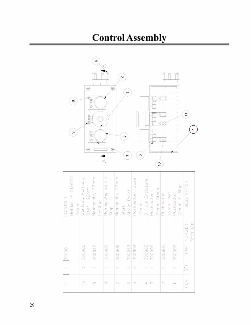
Control Assembly
AA
2
6
89
73
1
11
5
10
4
11
1300901
CONTACT,
NORMALLY CLOSED
22mm
10
3300902
Contact, Norm
ally
Open 22mm
91
300910
Nameplate, 22mm
E-Stop
81
300908
Nameplate, 22mm
Stop
71
300909
Nameplate, 22mm
Start
61
300213
Strain Relief
53
300904
Pushbutton, Base
22mm
41
300903
3 Hole Enclosure
31
300906
Pushbutton,
22mm Green
21
300905
Pushbutton,
22mm Red
11
300907
Pushbutton,
22mm E-Stop
Parts List
ITEM
QTY
PART NUMBER
DESCRIPTION

30
Notes

31
Notes

Best Diversified Products, Inc.107 Flint St.
Jonesboro, Arkansas 72401Phone: 870-935-0970
Toll Free: 800-327-9209Fax: 870-935-3661
Call Best Customer Service
99042