diverted neutrals
TRANSCRIPT
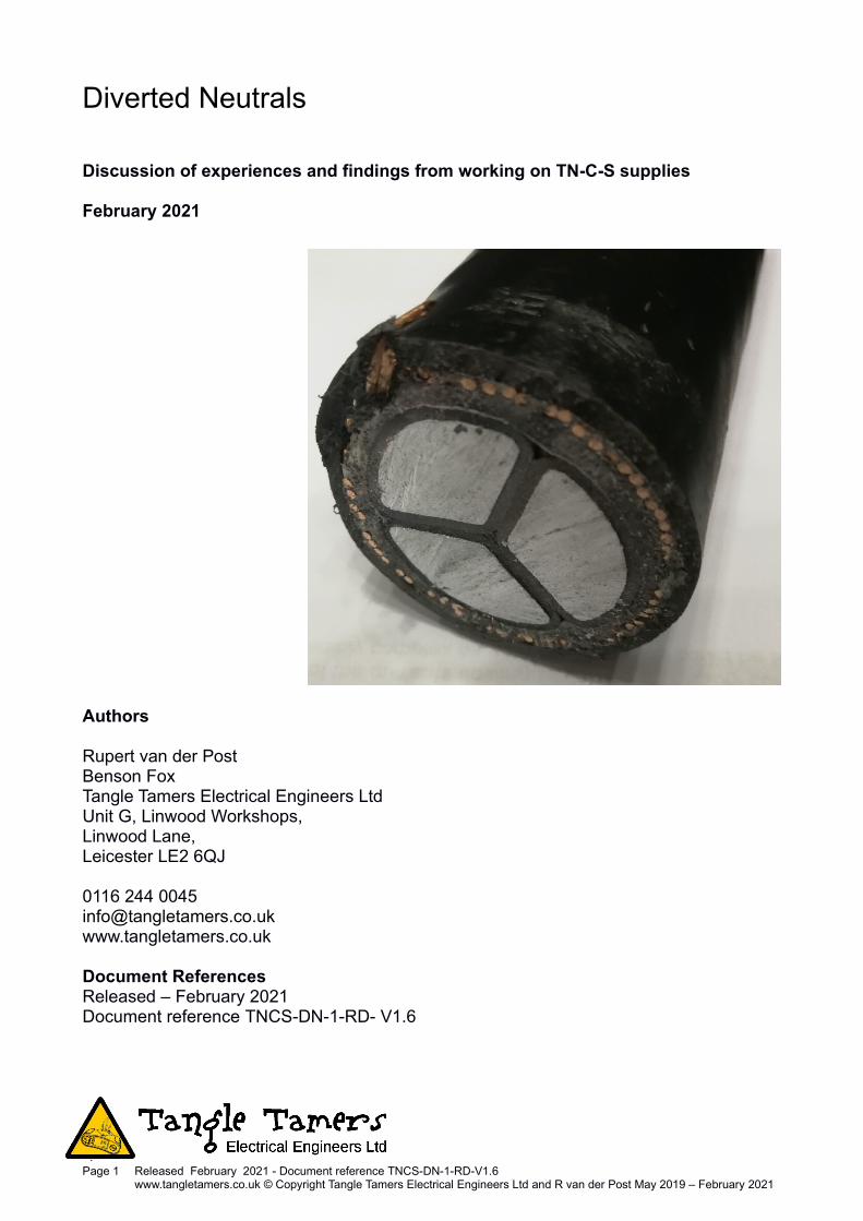
Diverted Neutrals
Discussion of experiences and findings from working on TN-C-S supplies
February 2021
Authors
Rupert van der Post Benson FoxTangle Tamers Electrical Engineers Ltd Unit G, Linwood Workshops,Linwood Lane, Leicester LE2 6QJ
0116 244 [email protected]
Document ReferencesReleased – February 2021Document reference TNCS-DN-1-RD- V1.6
Page 1 Released February 2021 - Document reference TNCS-DN-1-RD-V1.6www.tangletamers.co.uk © Copyright Tangle Tamers Electrical Engineers Ltd and R van der Post May 2019 – February 2021
Contents
Diverted Neutrals............................................................................................................................................ 1
Contents.......................................................................................................................................................... 2
Disclaimer........................................................................................................................................................ 3
Confidentiality & Copyright........................................................................................................................... 3
Thank-you........................................................................................................................................................ 3
Summary......................................................................................................................................................... 4
REC/DNO/DSO regulations and practice......................................................................................................5
Earth & protective conductor currents from TN-C-S...................................................................................6
SNE, TN-S, CNE, TN-C-S................................................................................................................................ 8
TN-C-S Diverted Neutral Currents................................................................................................................. 9
Scenario 1 – Ideal conditions.....................................................................................................9
Scenario 2 – Two interconnected TN-C-S supplies with a local load........................................10
Scenario 3 – Two interconnected TN-C-S supplies with a remote load....................................11
Scenario 4 – Three interconnected TN-C-S supplies with a remote load.................................12
Scenario 5 – The combined effects of Scenarios 1 – 4............................................................13
Some definitions – Also see BS7671..........................................................................................................14
Page 2 Released February 2021 - Document reference TNCS-DN-1-RD-V1.6www.tangletamers.co.uk © Copyright Tangle Tamers Electrical Engineers Ltd and R van der Post May 2019 – February 2021

DisclaimerThese background notes contain various information and opinions based on events and factsinvestigated. As with engineering judgement, ‘opinions’ are formulated based upon a review of theavailable evidence at a certain time and specific location.
The background information is general in nature, indicating tendencies we have observed on varioussites. We have taken all reasonable steps and exercised due care and attention while compiling theseitems. However, errors can happen, and specific equipment and circumstances can change outcomessignificantly. Therefore care should be exercised before designing or basing decisions on these itemswithout further expert input.
Confidentiality & CopyrightYou may share the whole of this document. Those whom you share it with may in turn share the wholeof the document. However, if you share a part of the document, you must reference the document fully.So, if you or subsequent recipients wish to quote from the document you should reference thedocument fully, as "Diverted Neutrals - some notes on TN-C-S supplies" R van der Post and B Fox –Feb 2021 - ref TN-C-S-DN-1-RD-V1.6.
Thank-youMany thanks to all the following for their help and input:
Paul Meenan and David Watts
Dan Jackson and John Ward
Ryan Dempsey and Paul Skyrme
collectively working together as the E5 Group.
And David M Barry, Ray Deacon, Colin Dente, Mike Suter and Richard Wardak
Page 3 Released February 2021 - Document reference TNCS-DN-1-RD-V1.6www.tangletamers.co.uk © Copyright Tangle Tamers Electrical Engineers Ltd and R van der Post May 2019 – February 2021
Illustration 1: Earthing systems don't always get looked after well, even if they’ve been installedcorrectly in the first place.

SummaryWe undertake varied work, much of it on buildings which contain equipment and processes which aresensitive to magnetic fields and particularly to changes in magnetic field. Such buildings include:
Electron microscopy and spectroscopy facilities
Secure data centres
Recording studios
Medical imaging locations
EMI / RFI screened rooms
Over the years, we have developed our knowledge and understanding of the causes of noise andinterference issues which can give these installations and equipment problems. We are particularlyinterested in low frequency noise and interference.
If currents flow in an installation's earthing and bonding network or its metallic structures, they cangenerate significant magnetic fields. The fields generated by currents flowing in these elements are notcancelled by fields from return conductors sitting right beside them. So their local magnetic fields arestrong and this causes problems.
Electricians are familiar with earth leakage, also known as residual currents, caused by high leakageplant and equipment such as rectifiers or inverter drives. A single item may generate anywhere from afew milliamps to many amps to earth. There is however, a lesser known phenomenon called DivertedNeutral Current (DNC) which can also cause current to flow in an installation’s earth network.
In an installation, a single TN-C-S supply to a building can give rise to diverted neutral currents that flowfrom the main earth terminal via bonding to extraneous-conductive-parts to the mass of earth (the“mud”). TN-C-S was also historically known as PME (Protective Multiple Earthing) - a common historicterm – for a more detailed discussion of types of supply system earthing see section 312.2 of BS7671:2018. Diverted neutral currents also can happen where two or more TN-C-S supplies have theirCNEs (Combined Neutral Earth conductors) connected in any way.
For example, think about a steel frame building. That building is split into two halves each with its owntheoretically-separate installation, each with its own TN-C-S supply.
However, BS 7671 (regulation 411.3.1.2 in the 18th edition 2018) requires that “in each installation mainbonding protective conductors complying with Chapter 54 shall connect to the main earthing terminalextraneous-conductive-parts including (i) Water installation pipes (ii) Gas installation pipes (iii) otherinstallation pipework and ducting (iv) Central heating and air conditioning systems (v) exposed metallicstructural parts of the building”.
Therefore to comply with BS 7671 each installation must have the steel frame, services and lightningprotection bonded to its own main earth terminal. This creates a common connection between the twoTN-C-S supplies, where neutral current from the supply head in one installation can flow (for example)through the building frame or shared service connections, to the second TN-C-S supply head and viceversa. A simplified similar situation is described with a drawing on page 10 in this document, titledScenario 2 - two interconnected TN-C-S supplies with a local load.
TN-C-S supplies can cause diverted neutral currents to flow in installation earthing and bondingnetworks. From there, the structures and services can then end up carrying diverted neutral currentswhen the supplies are not individually separated in stand-alone buildings. Also, some limited divertedneutral currents flow through the mass of earth (soil can be quite resistive).
It is not sufficient just to make the final cable drops to installations using separate CPCs. Similarly, it isnot enough to just make a single supply truly TN-S (even properly, all the way back to the substation),when there are also TN-C-S supplies in the area or in that shared building. Diverted neutral currentscan flow in something other than the neutral conductors. These currents can cause problems, hazardsand danger, particularly when a DNO CNE connection is lost or broken.
Page 4 Released February 2021 - Document reference TNCS-DN-1-RD-V1.6www.tangletamers.co.uk © Copyright Tangle Tamers Electrical Engineers Ltd and R van der Post May 2019 – February 2021

REC/DNO/DSO regulations and practiceThe regional electricity companies and distribution network operators commonly have rules or guidancewhich try to stop TN-C-S supply heads being connected together by low resistance earthing systems –e.g. avoiding multiple TN-C-S supplies being run into a common steel framed building, where each onewould be correctly connected, earthed and bonded to the requirements of BS7671. For example,Western Power Distribution’s document SD5C/2 (2017) states:
4.5.3 New (and replacement) incoming cables to multi-occupancy buildings shall be Separate Neutraland Earth (SNE) type.
However, it is very common in older buildings to see multiple CNE (Combined Neutral-Earth) supplycables right into the building. Furthermore, the REC/DNO/DSOs do not always abide by their ownrules. Illustration 2 shows just one recent example we have found of multiple TN-C-S supplies installedin the same building.
Page 5 Released February 2021 - Document reference TNCS-DN-1-RD-V1.6www.tangletamers.co.uk © Copyright Tangle Tamers Electrical Engineers Ltd and R van der Post May 2019 – February 2021
Illustration 2: 2 TN-C-S supplies installed in a common switch-room. Thanks to M. Harris
Earth & protective conductor currents from TN-C-STN-C-S supplies have many regulations surrounding them in BS7671. They are associated with anunderlying risk of neutral currents flowing in the earthing system of a single installation from the "earth"or (more realistically and using a less confusing word) the "mud" outside an installation.
The wiring regulations aim to ensure that an installation is ideally an intact single equipotential zone andthat the earthing and bonding conductors have cross-sectional areas which are sufficient to safely carrytheir currents under normal operation and fault conditions.
In “good” modern 3-phase systems neutral currents are often still big. Even where phase currents areperfectly balanced, the sum of the triplen harmonic currents appears on the neutral. The Regsacknowledges that neutrals may even need to be bigger than the phase conductors on occasion toaccommodate this. However, the Regs allow a default choice of protective conductors that have amuch smaller cross section than the phase conductors.
The arrival of section 607 in the 16th edition of BS7671 (“EARTHING REQUIREMENTS FOR THEINSTALLATION OF EQUIPMENT HAVING HIGH EARTH LEAKAGE CURRENTS” - and its successors)shows that protective conductors are expected to carry some current in various “normal” operatingconditions. However, little is said in the Regs about up-sizing protective conductors for significantstanding currents. The implication is that protective conductor currents are expected to be small, atleast relative to the protective conductor size and capacity. When diverted neutral currents are addedto the mix, this is not always true, and protective conductors should be sized appropriately for theirstanding currents as well as for any fault currents they may have to carry.
Page 6 Released February 2021 - Document reference TNCS-DN-1-RD-V1.6www.tangletamers.co.uk © Copyright Tangle Tamers Electrical Engineers Ltd and R van der Post May 2019 – February 2021
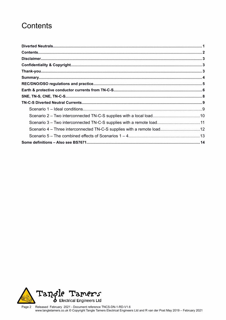
Illustration 3: Measurement on an Earth Conductor of current from a shared water system in a multi-occupancy brick building with multiple TN-C-S supplies

Secondarily, the Regs aim to ensure that the “earth” of a (TN-C-S) equipotential zone cannot readily betaken to outside locations where it might give danger (via the feed to a caravan, for example), withoutappropriate precautions. Where the earthing arrangements of multiple TN-C-S installations are cross-connected (whether correctly or even inadvertently) the problem becomes difficult: parallel neutral pathsare created through the earthing networks and the neutral current splits between the REC/DNO neutralpath and the installations’ earth paths.
Many locations with multiple TN-C-S supplies interconnect them at least by the arrangement of theservices, and by the bonding (even in brick buildings, and as the Regs require).
Illustration 3 shows a current measurement on the earth conductor in a business unit which is alaboratory. The current was low on the day the photograph was taken – historically we have seen over5 Amps here sometimes. In this unit, the water system is bonded to the TN-C-S head via the mainearth conductor and the main earth terminal.
The building’s water system is also bonded to other TN-C-S supply heads in a number of other unitsand in the shared common area of the building. This is a 1920s brick building but, even without a steelframe, we still find very significant currents flowing from supply head to supply head via the servicesand the bonding. The currents here are high enough that their magnetic fields ruin some types ofmeasurements in this laboratory.
As another example, we worked on a building that contained a large number of small recording studios,which had 3 separate TN-C-S supply heads within the building. The protective conductor system wascarrying over 25 Amps diverted neutral current flowing from supply head to supply head when wemeasured it, due to this supply configuration. Because the earth currents generated strong magneticfields, electric guitars could not be used in some of the studios.
This shows that the interpretations of the definitions of multi occupancy are not being followed properly(or even listened to, sometimes – in the last example, one of the supply heads fed a bunch of new flatsabove the studio complex...).
Note that a separate earth entering the premises is not sufficient on its own. The local REC/DNOnetwork, behind the final drop cables to the premises, may still be TN-C. The RECs often claim that anSNE (separate neutral and earth) cable entering the premises gives the premises TN-S.
This is not so. Consider if that premises has an SNE cable which connects to a CNE (common neutraland earth) cable in the street. Say the next-door unit in the same building also has an SNE cable to theCNE cable, connected to a different point on the CNE cable. Neutral current flowing through the CNEouter layer of the cable faces a parallel path through the 2 installations, if the systems, services, frame,lightning protection systems or other extraneous-conductive-parts of the 2 units interconnect to eachother in any way.
This sharing of currents via parallel paths continues while the various supply heads are connectedcorrectly. However, if the CNE conductor of one or more supplies breaks, the sharing path becomesthe path for all the neutral current which would otherwise have gone along the failed conductor. Thusthe sharing path can also become the path for load and fault currents, when it has already beencarrying an excessive standing current.
Page 7 Released February 2021 - Document reference TNCS-DN-1-RD-V1.6www.tangletamers.co.uk © Copyright Tangle Tamers Electrical Engineers Ltd and R van der Post May 2019 – February 2021

SNE, TN-S, CNE, TN-C-S....Using an SNE cable to a premises connects the customer's installation earth and neutral with separateconductors at the customer's installation. It does not guarantee to connect the other end to separatecable cores back to the substation star point and earth. It also gives no guarantee about the otherinstallations in a multi-occupancy building.
The utilities routinely install CNE-cabled TN-C networks, almost by default. However, using combinedneutral earth conductor cable within the wiring of the installation itself is regarded as a major defect anda very significant issue. Mud and concrete are resistive, they are not good insulators.
It has however become quite common practice for REC/DNOs to give an SNE final connection thatgoes back into the road: this then often joins on to a CNE (3-phase, 3 core + CNE armour) cable andcarries on that way back to the substation.
In our opinion, this is not TN-S. TN-S is a separated Neutral and Earth all the way back to thesubstation. Take a look at the drawing - Fig 3.8 “TN-S system” in the Regs, in 312.2.1.1 “Single sourcesystems”. The separation of the cpc and neutral goes all the way back to the transformer, not just to anarbitrary point a few metres outside an installation.
If the separation is not maintained all the way back to the source of supply for all the installations, thenwhen those installations' Earthing networks or bonded metalwork connect, you have a possible neutralpath via the earths. That path is in parallel with a length of the outer sheath / armour / CNE conductorof the DNO's cabling. The current flowing in each path is then determined primarily by the load on thedistribution network and the relative impedances of the two paths.
Finally, for now, it may be interesting for the reader to contemplate TN-C-S supplies in multiple earth-coupled installations, and to then consider what happens when the DNO CNE conductor breaks outsidethe installation(s).
The following appendix pages go into a deeper explanation of diverted neutral currents.
JR van der Post MBA BSc CEng MIET - Chief Electrical EngineerB Fox - Technician
Tangle Tamers Electrical Engineers Ltd 0116 244 [email protected]
Page 8 Released February 2021 - Document reference TNCS-DN-1-RD-V1.6www.tangletamers.co.uk © Copyright Tangle Tamers Electrical Engineers Ltd and R van der Post May 2019 – February 2021
Illustration 4: REC 3-phase cables – CNE & SNE thanks to P. Meenan

TN-C-S Diverted Neutral CurrentsScenario 1 – Ideal conditions
Illustration 5 shows a TN-C distribution network in ideal conditions. TN or ‘Terre Neutre’ references theearthed neutral on the secondary 230V/400V output of the DNO's / distribution network operator's 11kVtransformer. The ‘C’ in TN-‘C’ represents a single Combined neutral and earth return and protectiveconductor, also known as a CNE or PEN conductor, coming from there.
For simplicity below, one single phase TN-C supply is shown connected to all the properties. Where thesupply enters a property the combined neutral-earth conductor is ‘Separated’ at the supply head andthe supply becomes TN-C-‘S’. Property B has a load connected. The red arrows show where currentflows in this TN-C-S system under ideal conditions for one installation’s load.
Page 9 Released February 2021 - Document reference TNCS-DN-1-RD-V1.6www.tangletamers.co.uk © Copyright Tangle Tamers Electrical Engineers Ltd and R van der Post May 2019 – February 2021
Illustration 5: Single phase TN-C-S supply to a domestic property.
Low voltage earthnest or spike

Scenario 2 – Two interconnected TN-C-S supplies with a local load
Illustration 6 shows an installation (property B) with a load connected. In this scenario the earthingsystem for property B is connected by something to property A’s earthing system. The connectionbetween the earthing systems provides a parallel path for neutral current to flow back to the substationvia both supply heads from a single load. In this example neutral current splits or divides where theneutral and main earth conductor join the supply head and CNE conductor at the origin of the supply inB.
The proportion of the neutral current that flows into the earthing system depends on the resistance ofeach of the parallel paths. The size of the total current is governed firstly by the load on the supply.
Equally or similarly, any load applied to building A will also see the earth system interconnection as aparallel path for neutral current to flow through building B’s earthing system to B’s supply head and on.
The current for the most part will follow the path of least resistance within the buildings’ earthing,metallic structures and services. There will be some branching and distribution of the current becauseof the interconnection of any services. As a result, it is likely that currents will flow not just in in thesupplementary or main bonding conductors, but also in some CPC’s and metallic building structures.
Page 10 Released February 2021 - Document reference TNCS-DN-1-RD-V1.6www.tangletamers.co.uk © Copyright Tangle Tamers Electrical Engineers Ltd and R van der Post May 2019 – February 2021
Illustration 6: TN-C-S supply where two earth systems have been interconnected.
Low voltage earthnest or spike

Scenario 3 – Two interconnected TN-C-S supplies with a remote load
Illustration 7 demonstrates how current from a remote load elsewhere on the same network can flowthrough the Earthing systems of property A and B where both earthing systems are interconnected. Inthis instance, the electricity network sees the earth system of these two buildings as a parallel path forneutral current to flow through. This is due to the combined neutral and protective earth conductor or‘CNE’ conductor of the main DNO network cable.
The part of current that flows through the earthing system depends on the ratio of the resistance of theCNE conductor going past properties A and B, and the combined resistance of both properties’ earthingnetworks. For example, if the combined earth network resistance of property A and B is lower than theCNE conductor then a majority of the neutral current will flow in their earth systems. The total currentthat flows through the earth systems will vary with the load.
Page 11 Released February 2021 - Document reference TNCS-DN-1-RD-V1.6www.tangletamers.co.uk © Copyright Tangle Tamers Electrical Engineers Ltd and R van der Post May 2019 – February 2021
Illustration 7: Single phase TN-C-S supply where two earth systems have been interconnected with a remote load.
Low voltage earthnest or spike
Scenario 4 – Three interconnected TN-C-S supplies with a remote load
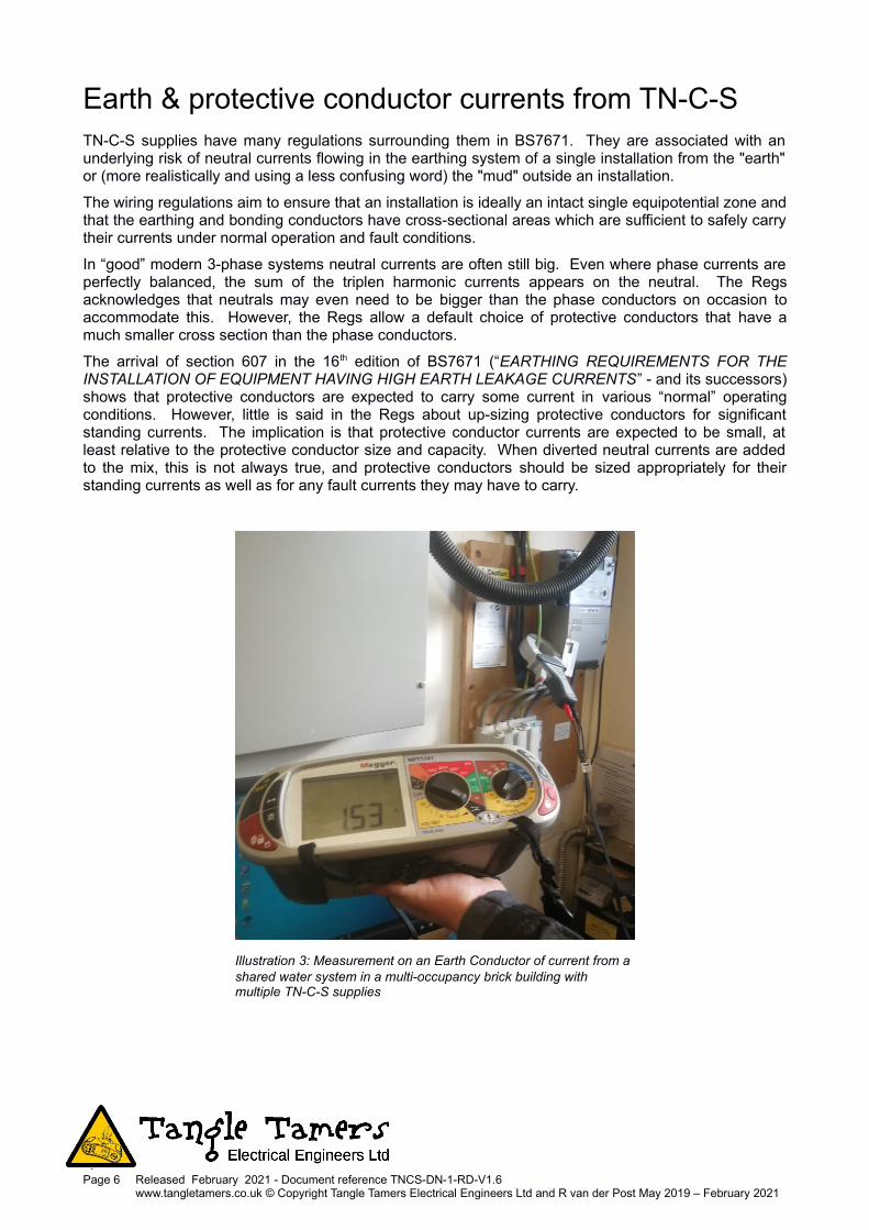
Illustration 8 shows what would happen if 3 installations' earth networks are interconnected. Howeverthis time the DNO feed cable to property B is fully disconnected from the electricity distribution network.Despite that isolation, because there is a conductive path through property B between property A andC, current still flows through property B’s earth system. This current does not depend on B’s externalDNO earthing connection. B's supply cable is fully disconnected, but current can still flow from A to C.
The path from A to C through property B could be any conductive structure or services installed in orentering the buildings. For example, rebar, structural beams, or water and gas service pipes. Old waterpipes left in the ground or even a metal stud or a fixing shorted to the rebar of a neighbouring buildingcan also form part of a route for current to flow. The path can be anything that electrically couples twoor more buildings' earthing systems together.
This can be particularly problematic in multiple occupancy buildings where BS7671 requires eachinstallation to be at least main-bonded. The issue can be made worse where class 1 equipment withhigh leakage current is installed with its own CPC but in addition is fixed down so that its casing isfortuitously connected to bonding elsewhere (e.g. a pump on a water system).
In South Manchester, the local utility invested in “upgrading” a town centre with new PME cabling. Aretailer with large chiller loads in a 50 year old building was given a new TN-S supply from an oldsubstation ~15 metres away. This supply suffered diverted neutral current pollution of about 5 Ampsfrom nearby units in the same building. When challenged, the utility had no record of measurements onearth electrodes which should have been installed at the cable joints. The “core balance” or residualcurrent measured at the substation peaked at more than 50 Amps.
Page 12 Released February 2021 - Document reference TNCS-DN-1-RD-V1.6www.tangletamers.co.uk © Copyright Tangle Tamers Electrical Engineers Ltd and R van der Post May 2019 – February 2021
Illustration 8: TN-C-S supply where 3 earth systems have been interconnected, with a remote load. Property B has been isolated from the supply network.
Low voltage earthnest or spike

Scenario 5 – The combined effects of Scenarios 1 – 4
Illustration 9 demonstrates the resultant mess that occurs when multiple loads and earth bondinginterconnections exist on the same TN-C-S network.
Current generated by the Remote Property flows into building A, B and C. Some of the current flowingthrough the load in building B goes into buildings A and C and vice-versa. Currents going back and forthbetween the buildings will sum and cancel depending on the magnitudes and phase angles. We haven'tadded loads in A or C yet. And in a 3 phase system, these relationships are even more complex.
From Kirchhoff’s laws, the net ‘return’ or neutral current of balanced 3-phase loads is effectively zero.Where the load on a 3 phase 4 wire system is not balanced the un-balanced part of the current appearsas neutral current. Triplen harmonics make the situation worse. They sum on the neutral, rather thancancelling. On one site (approx. 110 Amps 3-phase demand), the phase currents were balanced towithin a few amps. Yet the installation still had a neutral current of more than 30 Amps due to theharmonics.
Installations, if they are 3 phase with some form of connected earthing, then share their neutral currentwith each other due to the interconnections. Here, harmonics and phasing of the current on the neutralbecome important. The relationship between the loading of the network at any given time and thecancelling effects of the currents flowing becomes incredibly complex. There are then many scenarioswhich could be in play – so diagnosis becomes very, very difficult.
Page 13 Released February 2021 - Document reference TNCS-DN-1-RD-V1.6www.tangletamers.co.uk © Copyright Tangle Tamers Electrical Engineers Ltd and R van der Post May 2019 – February 2021
Illustration 9: The combined effects of multiple cross linked TN-C-S supplies with multiple loads on a distribution network
Low voltage earthnest or spike
Some definitions – Also see BS7671BS 7671: “Requirements for Electrical Installations” – The IET wiring Regulations. The Regs.
Combined Neutral Earth (CNE) Cable: One where a separate circuit protective conductor (CPC) is notincluded in the cable structure. Instead the cable combines the functions of the Neutral and the ProtectiveConductor into one CNE conductor. Hence a single phase cable in an installation is commonly 3 core or 2core plus armour, to include a separate CPC. However, in many common distribution systems a single coreplus CNE armour cable would be used as a single phase cable – a “CNE cable”
Diverted Neutral Current (DNC): A DNO’s or a consumer’s neutral current which flows partly or wholly in apath other than its own circuits’ neutral conductor(s). Commonly these flow in earth networks, earthedstructures, service pipes, rebar and drainage systems, together with a variety of CPCs and their associatedequipment structures, CNE conductors and also the mud of earth itself.
Electrical Installation (abbr: Installation): Ref BS7671 (The “Regs”): An assembly of associated electricalequipment having co-ordinated characteristics to fulfil specific purposes. In practice, commonly understoodas being the fixed electrical system of one user or company, in one location.
Earth Leakage Current (Protective Conductor Current): Ref BS7671 Electric current appearing in aprotective conductor, such as leakage current, or current from an insulation fault. In practice, commonlytaken to mean a residual current e.g. in equipment and its CPCs (Circuit Protective Conductors), bondingand earthing, bonded services and structures.
Main Earth Conductor: Ref BS7671: Earthing Conductor: A protective conductor connecting the mainearthing terminal of an installation to an earth electrode or other means of earthing. In practice, we use theterm "Main Earth Conductor" instead of Earthing Conductor, for clarity, when talking about earthing systems.This helps avoid confusion between an earth conductor and the earthing conductor (because those latterexpressions are so very close to each other, causing misunderstanding in discussions).
MUD, MoE, Mass of Earth: The electrical industry talks of the Mass of Earth, and Earthing and Earth andGround and Grounding and many similar words: Yet everyone seems to have a bit of confusion and lack ofclarity in discussions about Earthing systems. About 10 years ago we started using the term “Mud” to denotethe Mass of Earth – remote from the zone of influence of the earth electrodes under discussion, the stuff ofwhich Terra Firma is made – to try to avoid misunderstandings. We therefore use it here.
REC / DNO / DSO / IDSO: The DNOs (Distribution Network Operators) are the successors to the distributionarms of the RECs (Regional Electricity Companies). Their geographical operating areas reflect theboundaries of the old electricity boards prior to deregulation back in the 90’s. There will be increasingimplemented of micro-generation technologies in future: Hence DNO’s will progressively to take on DSO(Distribution System Operator) responsibilities. IDSOs are independent. Relevant acronyms may include:
LEB - London Electricity Board REC - Regional Electricity Companies
DNO - Distribution network Operator BNO - Building Network Operator
IDNO - Independent Distribution Network Operator DSO - Distribution System Operator
EDNO - Licence Exempt DNO
Residual Current: Ref BS 7671 Algebraic sum of the currents in the live conductors of a circuit at a point inthe electrical installation. In practice, commonly understood to mean the net difference or imbalance betweenthe phase and neutral currents in a single phase circuit. By extension, the net difference in the currents in a3 phase circuit’s 3 or 4 live conductors. Note that some of this current may go down paths other than theCPCs (Circuit Protective Conductors), such as metal pipes connected to equipment. Some of this currentcan also leave the installation via extraneous-conductive-parts such as service pipes.
Triplen Harmonics: Ref BS 7671 The odd multiples of the third harmonic of the fundamental frequency(e.g. the 3rd, 9th ,15th 21st). In practice, commonly understood to mean 150, 450, 750, 1050 Hz etc. on a50 Hz system.
Page 14 Released February 2021 - Document reference TNCS-DN-1-RD-V1.6www.tangletamers.co.uk © Copyright Tangle Tamers Electrical Engineers Ltd and R van der Post May 2019 – February 2021