diy: synesthesia project - homewood student...
TRANSCRIPT
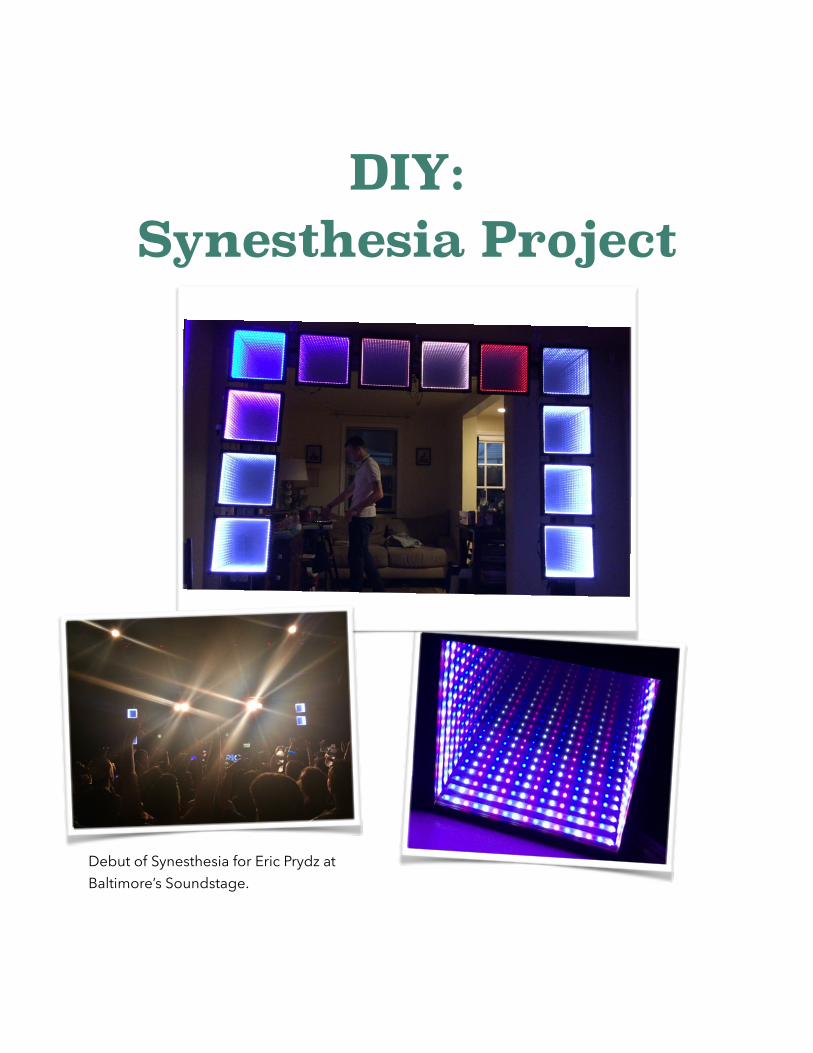
DIY: Synesthesia Project !
!
Debut of Synesthesia for Eric Prydz at Baltimore’s Soundstage.

!Brief Background: !
This project was funded by a Creative Use of Technology Grant offered by the Digital Media Center at Johns Hopkins University. The goal of the project was to create an immersive, live, musical performance piece that provides the means to not only engage an audience’s auditory senses, in the traditional manner through sounds, but also their visual senses through tightly-coupled, vibrant, visual displays. The project name, “Synesthesia”, refers to a an extraordinary sensory condition in which one sense (for example, hearing) is simultaneously perceived as if by one or more additional senses such as sight.
!Project Build: !
The heart of the project is the Teensy micro-controller (http://www.pjrc.com/teensy/). The Teensy is very much like an arduino or a raspberry pi, but it has many advantages because it is a class compliant device, which means it does not require the installation of drivers to be used. Teensy is also powerful because its developer has ported the well known Arduino library, under the name Teensyduino, to the Teensy opening up the door for the mainstream Arduino sketches to be compatible on a class compliant device.
With exponential growth in DIY and Makers over the past years many companies have popped up to explicitly serve this growing community. LED projects seem to be at the top of many Makers lists and LED light strips have become increasingly available and incorporated in many complex projects. Teensy developer, Paul Stoffregen, decided to make an extremely computationally efficient high performance LED library, called OctoWS2811 (http://www.pjrc.com/teensy/td_libs_OctoWS2811.html), which allows Teensy to simultaneously update 8 LED strips at the same time. Additionally, he designed an adaptor board (http://www.pjrc.com/store/octo28_adaptor.html) that sits on top of the teensy to simplify the electronics to where you only have to attach the power and two ethernet cords. Before the development of this sophisticated library, being able to create multiple LED integrated visual displays would have been limited to the more advanced programmers familiar with both the
!

intricacies of the LEDs and the coding. Now it is easily approachable to novice Makers such as myself and many others.
The design of Synesthesia was inspired by a combination from multiple Makers’ smaller builds found on the internet, but many of the modular hardware design ideas stem directly from this Makers blog (http://www.enviral-design.com/ ) . The concepts of the individual displays being modular lend Synesthesia the capability of having diverse arrangements of panels to create different geometrical presentation environments. The infinity mirrors were chosen because they are a great visual medium that adds a huge element of depth with a minimum amount of LEDs. The panels were initially going to be made using shadowboxes, but cost restrictions led to us making them from scratch. What follows are the basic steps to make the project for yourself.
!Enjoy!
Nathan Towles - Evan Reynolds
!
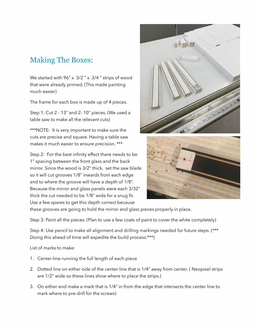
Making The Boxes: !We started with 96” x 3/2 ” x 3/4 ” strips of wood that were already primed. (This made painting much easier)
The frame for each box is made up of 4 pieces.
Step 1: Cut 2 - 13” and 2- 10” pieces. (We used a table saw to make all the relevant cuts)
***NOTE: It is very important to make sure the cuts are precise and square. Having a table saw makes it much easier to ensure precision. ***
Step 2: For the best infinity effect there needs to be 1” spacing between the front glass and the back mirror. Since the wood is 3/2” thick, set the saw blade so it will cut grooves 1/8” inwards from each edge and to where the groove will have a depth of 1/8”. Because the mirror and glass panels were each 3/32” thick the cut needed to be 1/8” wide for a snug fit. Use a few spares to get this depth correct because these grooves are going to hold the mirror and glass pieces properly in place.
Step 3: Paint all the pieces. (Plan to use a few coats of paint to cover the white completely)
Step 4: Use pencil to make all alignment and drilling markings needed for future steps. (*** Doing this ahead of time will expedite the build process.***)
List of marks to make:
1. Center-line running the full length of each piece
2. Dotted line on either side of the center line that is 1/4” away from center. ( Neopixel strips are 1/2” wide so these lines show where to place the strips.)
3. On either end make a mark that is 1/4” in from the edge that intersects the center line to mark where to pre-drill for the screws)
!

Step 5: Pre-drill 2 holes in the 13” pieces for the screws that will join the box together. We ended up making a paper guide to help us center the hole to align properly. The guide holes should be 1/4” in from the edge and centered between the two grooves. These holes are necessary because the wood kept splitting at the ends.
Step 6: Drill 2 more holes in 13” pieces 7/8-1” in from the edge. These are used to pass the wires to the outside of the boxes. We wish this step wouldn't have been necessary, but soldering the short wires in the corners was a nightmare. Having the exit holes allowed for us to have a quicker assembly line process for making many boxes.
Step 7: Make 2 “L-shaped” pieces by joining a 10” and a 13” piece. Use clamps to help position the vertical 10” piece where it is flush with the end of the 13” piece and the grooves intersect cleanly. (***Once you have made sure everything is lined up***) Use pre-drilled hole from “Step 5” to screw the pieces together.
!
!

Making The 2 Way Mirrors: !We used glass because it was cheap, but if you have extra money we would recommend using plexiglass or something similar to have a more durable design that does not shatter. Additionally, because square 12” x 12” glass panes aren't common we had to purchase 12” x 16” panes and get them cut to the right dimensions at Lowes. (**The edges were very sharp**)
To make the 2 way mirror, we used a “Privacy Control Window Film” made by Gila, which can be found online at Home Depot. We also got the recommended application kit, which is most useful for the solution you spray on during application.
**Note: This film comes in a tight roll and is rather difficult to deal with because it wants to curl up. We ended up cutting it into pieces that are slightly larger than the glass pane, which helped, but you still need 2 people to do this part of the job. ***
!Step 1: Cut film into manageable pieces that are at least 15” x 15”.
Step 2: Clean the glass surface thoroughly with water. And wipe it down with lent free paper towel (e.g. the blue shop towels you find in the automotive section at Walmart). (Repeat this step at least twice because there will inevitably be some speck of glass or dirt on the pane that you could have removed had you done this step better.)
Step 3: Follow the instructions included in the film box. If you follow these you will be fine.
http://www.gilafilms.com/help-how-tos also has helpful videos on the process.
!

(*** Note: the “application card” that comes with the application kit is not ideal and can scratch the film pretty easily. I recommend using a real squeegee. We actually used a squeegee for silk screening and it worked superbly.***)
Step 4: Cut excess off the edge using the cutter from the application kit. Alternatively, an exact-o knife and a straight edge will work well. Lay the glass pane with the newly applied mirror film FACE DOWN on a paper towel with a book on top. Let dry overnight.
Preparing the Neopixels: Neopixels are one of Adafruits signature LED strips products. These have the WS2812b integrated chips that allow them to function natively with the OctoWS2811 Library and Adaptor. We ordered ours through adafruit for convenience, but there are many other places you could purchase them. The strips are sold in 1 meter lengths that have 60 pixels per meter.
Step 1: From a larger roll of neopixels, we cut 4 segments that each had 17 pixels for each box. When cutting through the copper pads, make sure that you bisect the strips so you have equal amounts of copper on either side to make a good connection.
Step 2: It is helpful at this point to go ahead and prepare all of your segments of wiring needed. Use solid core wiring if possible.
- For the start strip you will want to have extended lengths of wire (We used about 8”-12” lengths). Its also easier if you have 2 grounds entering into the strip (1 for power ground , 1 for data ground) . All in all you will need to have 4 extended lengths entering (1 power, 1 data, 2 grounds) and 3 shorter (about 4”-6”) lengths exiting to chain to the next strip. (1 power , 1 data, and 1 ground)
- For the other 3 strips in the chain you can just cut 6 shorter lengths for each side (2 power , 2 data, and 2 ground)
- By now you should have a total of 25 wires ( 8 power, 8 data, 9 ground) .With all the wires cut, you can now strip small parts of each end of all the wires.
!

Step 3: Data only flows one direction on the strips (indicated by the arrows) and is only relayed to the contiguous pixel. This means you must connect the data-out pad on the 17th pixel of a segment directly to the data-in pad of the 1st pixel on the next segment. The power and ground can really be connected wherever as long as there is a connection between each segment. This is useful because you can use the larger pads (that weren't cut) to solder the wires of each power and ground to each end of a strip. * This can be seen in the image above* Then its easier to only solder the data wires to the small pads on either end.
Step 4: Once you have good connections, which you have verified by lighting each segment up separately, as well as joined together and with a voltmeter, use a hot glue gun on every soldered joint to stabilize the connections. ** The smaller pads are especially vulnerable to breaking off as you can see in the image above**
Assembling the Boxes: At this point you should have all your strip segments prepared with the wires soldered to each end. Additionally, the framed L-joints should be ready with the proper alignment markings to help place the neopixel strips centered.
Step 1: To attach the strips we used heavy-duty double-sided duct tape that can be purchased at a hardware store. Cut the tape into long strips about 1/2” wide and place it between the two lines that indicate the width of the neopixel strips.
Step 2: Place the neopixel strips where the middle of the 9th pixel from either end lines up with the centerline of the frame.
!

***REMEMBER***Data flows only one direction so you need to make sure you orient the strips to where they make a complete loop! Take your time and make sure you get the placement of the strips right before you close the boxes. ***
Step 3: Check to make sure all the strips are in the right position and test all the connections one more time. Next guide the wire ends through the exit holes in the frame.
Step 4: Clean the surface of the back-mirror and 2-way front-mirror with Windex (multiple times). Slide the back-mirror in the back grooves and then place the 2-way front-mirror in the front slot. ** The film side should face toward the INSIDE of the box** Screw the two L-Joints together to hold everything together tightly. Be careful not to over tighten because you could inadvertently crack one of the pieces of glass.
Step 5: Match the appropriate wire pairs together outside the box. Solder all the pairs together and you are finished with the box.
!Interfacing with the Teensy: !At this point you just need to wire up the power and one of the grounds to a 5V power supply. The other ground and the data line will be wired to the Teensy using an ethernet cable. Read through the details on the OctoWS2811 adaptor at https://www.pjrc.com/store/octo28_adaptor.html . This will explain the necessary steps needed to get the box started making visuals.
!
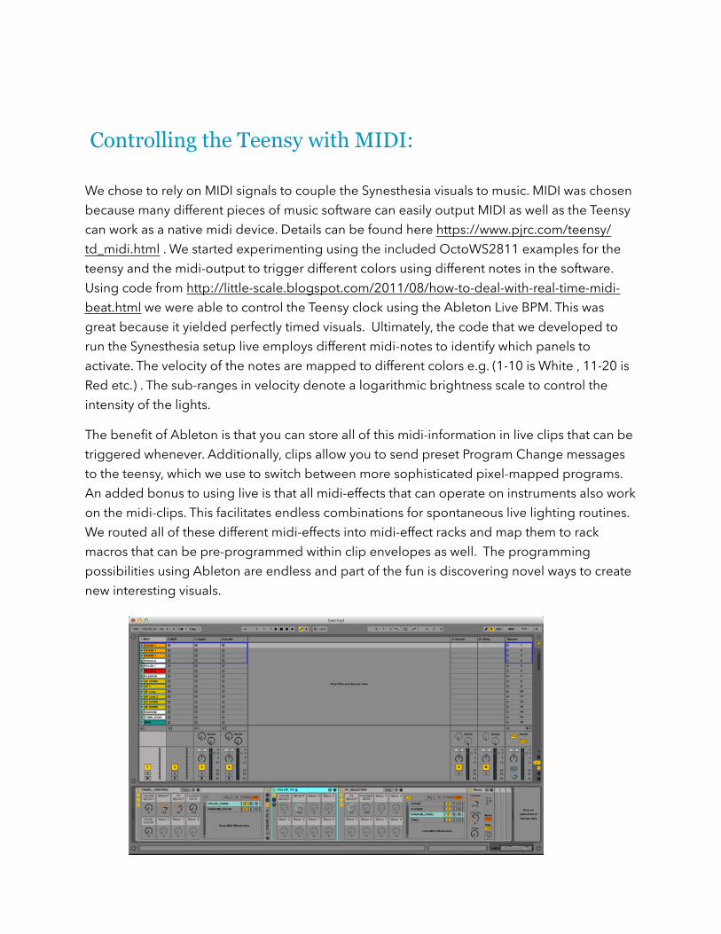
Controlling the Teensy with MIDI: !We chose to rely on MIDI signals to couple the Synesthesia visuals to music. MIDI was chosen because many different pieces of music software can easily output MIDI as well as the Teensy can work as a native midi device. Details can be found here https://www.pjrc.com/teensy/td_midi.html . We started experimenting using the included OctoWS2811 examples for the teensy and the midi-output to trigger different colors using different notes in the software. Using code from http://little-scale.blogspot.com/2011/08/how-to-deal-with-real-time-midi-beat.html we were able to control the Teensy clock using the Ableton Live BPM. This was great because it yielded perfectly timed visuals. Ultimately, the code that we developed to run the Synesthesia setup live employs different midi-notes to identify which panels to activate. The velocity of the notes are mapped to different colors e.g. (1-10 is White , 11-20 is Red etc.) . The sub-ranges in velocity denote a logarithmic brightness scale to control the intensity of the lights.
The benefit of Ableton is that you can store all of this midi-information in live clips that can be triggered whenever. Additionally, clips allow you to send preset Program Change messages to the teensy, which we use to switch between more sophisticated pixel-mapped programs. An added bonus to using live is that all midi-effects that can operate on instruments also work on the midi-clips. This facilitates endless combinations for spontaneous live lighting routines. We routed all of these different midi-effects into midi-effect racks and map them to rack macros that can be pre-programmed within clip envelopes as well. The programming possibilities using Ableton are endless and part of the fun is discovering novel ways to create new interesting visuals.
!