dk3162app5
DESCRIPTION
rotordynamicsTRANSCRIPT

APPENDIX 5
Gyroscopic Rotor Responses to Synchronousand Nonsynchronous Forward and
Backward Perturbation
the synchronous and nonsynchronous forward and backward perturbation, using differentialtechniques. This data was used for identification of the system parameters.
The differential technique was used in order to eliminate the effect of any possibleunknown residual unbalance in the main rotor. During the first startup of the rotor the inputunbalance weight with mass ‘‘m’’ is installed in the perturbation disk at radius r at 0�. Duringthe second startup the same unbalance weight is installed at the same radius but at 180�
orientation. The filtered 1� response vector data from the first and the second runs are then
thus with the magnitude 2mr!2 and located at 0�.The full spectrum cascade plots were obtained from the rotor direct response data
while long rotor was unstable. The threshold of instability occurred at about 2200 rpm,and with increase of rotational speed was followed by the oil whirl self-excited vibrations
1001
© 2005 by Taylor & Francis Group, LLC
The data presented in Figures A5.1–A5.12 illustrate short and long rotor responses to
vectorially subtracted, providing a clean 1� response of the rotor to the double input force,
(Figures A5.2, A5.4, A5.6, A5.8, A5.10 and A5.12). The short rotor system was stable,
(see Figure A5.8).

Figure A5.1 Bode and polar plots of synchronous perturbation of gyroscopic rig in stable (short rotor)
configuration: (a) Vertical and (b) Horizontal responses. Data reduced using differential technique.
Unbalance mass¼ 0.4 g at 0� and 114 mm radius. Disk mounted on the shaft at 51 mm from
centerline of rolling element support bearing (driver end). Nonsynchronous perturbator wheel
mounted on the rotor at 95mm from centerline of rolling element support bearing (driver end). Oil
pressure¼14 kPa. Shaft diameter¼ 25.3 mm, length to center of fluid bearing¼ 147 mm from
centerline of rolling element support bearing (driver end). An apparent decrease of phases at low
speed is associated with very low amplitude level, thus an inaccurate phase reading.
1002 ROTORDYNAMICS
© 2005 by Taylor & Francis Group, LLC

Figure A5.2 Direct orbits at various speeds (a) and full spectrum cascade plot (b). Synchronous perturbation of
rig in stable configuration. Unbalance mass¼0.4 g at 0� and 114 mm radius. Disk mounted to the
shaft at 51 mm from centerline of rolling element support bearing (driver end). Nonsynchronous
perturbator wheel mounted to the shaft at 95mm from centerline of rolling element support
bearing (driver end). Oil pressure¼14 kPa, shaft diameter¼ 25.3 mm, length to center of fluid
bearing¼147 mm from centerline of rolling element support bearing (driver end).
GYROSCOPIC ROTOR RESPONSES TO PERTURBATION 1003
© 2005 by Taylor & Francis Group, LLC

Figure A5.3 Bode and polar plots of nonsynchronous forward perturbation of gyroscopic rig in stable configura-
tion; (a) Vertical and (b) Horizontal responses. Data reduced using differential technique. Shaft
speed¼ 200 rad/s. The whirl resonance occurs at about 1000 rpm. Unbalance mass¼ 3.53 g
at 0� and 38 mm radius. Disk mounted on the shaft at 51 mm from centerline of rolling element
support bearing (driver end). Nonsynchronous perturbator wheel mounted on the rotor at 95 mm
from centerline of rolling element support bearing (driver end). Oil pressure¼ 14 kPa, shaft
diameter¼25.3 mm, length to center of fluid bearing¼ 147 mm from centerline of rolling element
support bearing (driver end).
1004 ROTORDYNAMICS
© 2005 by Taylor & Francis Group, LLC

Figure A5.4 Direct orbits at various speeds (a) and full spectrum cascade plot (b). The same data as in
rotation 200 rad/s. The higher harmonics of these vibrations are also in the spectrum.
GYROSCOPIC ROTOR RESPONSES TO PERTURBATION 1005
© 2005 by Taylor & Francis Group, LLC
Figure A5.3. The vibrations at frequency slightly lower than 2000 cpm correspond to rotor constant

Figure A5.5 Bode and polar plots of nonsynchronous backward perturbation of gyroscopic rig in stable
configuration. (a) Vertical and (b) Horizontal responses. Data reduced using differential technique.
Shaft speed¼200 rad/s. Unbalance mass¼3.53 g at 0� and 38 mm radius. Disk mounted on the
shaft at 51 mm from centerline of rolling element support bearing (driver end). Nonsynchronous
perturbator wheel mounted on the rotor at 95 mm from centerline of rolling element support
bearing (driver end). Oil pressure¼ 14 kPa, shaft diameter¼ 25.3 mm, length to center of fluid
bearing¼ 147 mm from centerline of rolling element support bearing (driver end). Note that fluid
whirl resonance does not occur for this backward perturbation.
1006 ROTORDYNAMICS
© 2005 by Taylor & Francis Group, LLC

Figure A5.6 Direct orbits at various speeds (a) and full spectrum cascade plot (b). The same data as in
on the backward side of the plot. It corresponds to the constant rotational speed 200 rad/s of
the rotor.
GYROSCOPIC ROTOR RESPONSES TO PERTURBATION 1007
© 2005 by Taylor & Francis Group, LLC
Figure A5.5. Note the constant amplitude vibration component with frequency about 2000 cpm

Figure A5.7 Bode and polar plots of synchronous perturbation of gyroscopic rig in unstable configuration.
(a) Vertical and (b) Horizontal response. Data reduced using differential technique. Unbalance
mass¼ 1.18 g at 0� and 114 mm radius. Disk mounted on the shaft at 259 mm from centerline of
rolling element support bearing (driver end). Nonsynchronous perturbator wheel mounted
on the rotor at 229 mm from centerline of rolling element support bearing (driver end). Oil
pressure¼7 kPa, shaft diameter¼ 25.3 mm, length to center of fluid bearing¼300 mm from
centerline of rolling element support bearing (driver end).
1008 ROTORDYNAMICS
© 2005 by Taylor & Francis Group, LLC
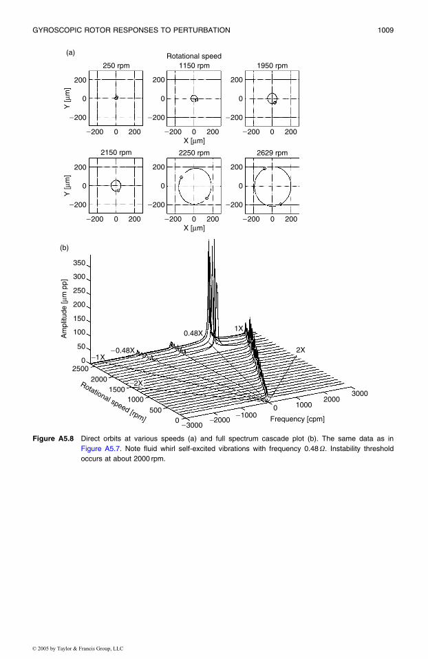
Figure A5.8 Direct orbits at various speeds (a) and full spectrum cascade plot (b). The same data as in
occurs at about 2000 rpm.
GYROSCOPIC ROTOR RESPONSES TO PERTURBATION 1009
© 2005 by Taylor & Francis Group, LLC
Figure A5.7. Note fluid whirl self-excited vibrations with frequency 0.48O. Instability threshold

Figure A5.9 Bode and polar plots of nonsynchronous forward perturbation of gyroscopic rig in unstable
configuration: (a) Vertical and (b) Horizontal response. Data reduced using differential techni-
que. Shaft speed¼200 rad/s. Unbalance mass¼ 2.20 g at 0� and 38 mm radius. Disk mounted
on the shaft at 259 mm from centerline of rolling element support bearing (driver end).
Nonsynchronous perturbator wheel mounted on the rotor at 229 mm from centerline of
rolling element support bearing (driver end). Oil pressure¼7 kPa, shaft diameter¼ 25.3 mm,
length to center of fluid bearing¼300 mm from centerline of rolling element support bearing
(driver end). Note fluid whirl resonance at the perturbation speed slightly lower than 1000 rpm.
1010 ROTORDYNAMICS
© 2005 by Taylor & Francis Group, LLC

Figure A5.10 Direct orbits at various speeds (a) and full spectrum cascade plot (b). The same data as in
rotor rotation at 200 rad/s and its 1x vibrations, due to imbalance. The use of the differential
technique did not perfectly eliminate the rotor imbalance.
GYROSCOPIC ROTOR RESPONSES TO PERTURBATION 1011
© 2005 by Taylor & Francis Group, LLC
Figure A5.9. The large amplitude and constant frequency, about 2000 cpm, corresponds to the

Figure A5.11 Bode and polar plots of nonsynchronous backward (Y�X) perturbation of gyroscopic rig in
unstable configuration. (a) Vertical and (b) Horizontal responses. Data reduced using differential
technique. Shaft speed¼200 rad/s Unbalance mass¼ 2.20 g at 0� and 38 mm radius. Disk
mounted on the shaft at 259 mm from centerline of rolling element support bearing (driver end).
Nonsynchronous perturbator wheel mounted on the rotor at 229 mm from centerline of rolling
element support bearing (driver end). Oil pressure¼7 kPa, shaft diameter¼25.3 mm, length to
center of fluid bearing¼300 mm from centerline of rolling element support bearing (driver end).
No fluid whirl resonance at backward perturbation.
1012 ROTORDYNAMICS
© 2005 by Taylor & Francis Group, LLC

Figure A5.12 Direct orbits at various speeds (a) and full spectrum cascade plot (b). The same data as in
synchronous vibrations.
GYROSCOPIC ROTOR RESPONSES TO PERTURBATION 1013
© 2005 by Taylor & Francis Group, LLC
Figure A5.11. The constant frequency (around 2000 cpm) component corresponds to the rotator