dlja oir ii r-t> - nasa · dlja_oir ii r-t>... _ ca& f^ bf5* v" i i ... mctuwc valve...
TRANSCRIPT

FOR
DLD GAS ATTITUDE CONTROL JET VALVES
DLJA_Oir II r-t>... _
C A& f^ BF5* V" I I£» ^^ b k • •MBnL ^/ m a II H HJv % ^hv^ ^^^1 B I IHHI
COPY
J E T P R O P U L S I O N L A B O R A T O R Y
C A L I F O R N I A I N S T I T U T E O F T E C H N O L O G Y
P A S A D E N A , C A L I F O R N I A
https://ntrs.nasa.gov/search.jsp?R=19730010749 2018-06-21T23:12:33+00:00Z
1PACEJYSTEMS
•' 3
'*"' ^C-.
-w
*£,-.......:&
70SD4285November 1970
A SOLENOID FAILURE DETECTION SYSTEM
FOR
COLD GAS ATTITUDE CONTROL JET VALVES
PHASE II FINAL REPORTCOVERING THE PERIOD MARCH 1969 TO JULY 1970
UNDER CONTRACT JPL 952578
PREPARED FOR
JET PROPULSION LABORATORYCALIFORNIA INSTITUTE OF TECHNOLOGY
4800 OAK GROVE DRIVEPASADENA, CALIFORNIA 91102
This work was performed for the Jet Propulsion Laboratory,California Institute of Technology, sponsored by theNational Aeronautics and Space Administration underContract NAS7-100.
G E N E R A L E L E C T R I C

70SD4285November 1970
A SOLENOID FAILURE DETECTION SYSTEM
FOR
COLD GAS ATTITUDE CONTROL JET VALVES
PHASE II FINAL REPORTCOVERING THE PERIOD MARCH 1969 TO JULY 1970
UNDER CONTRACT JPL 952578
PREPARED FOR
JET PROPULSION LABORATORYCALIFORNIA INSTITUTE OF TECHNOLOGY
4800 OAK GROVE DRIVEPASADENA, CALIFORNIA 91102
PREPARED By
PHILLIP A. JOHNSTON
PRODUCT MANAGER — NUCLEAR APPLICATIONS
APPROVED BY
GERALD C. HUTH
MANAGER — PRODUCT RESEARCH
SPACE TECHNOLOGY PRODUCTS
SPACE TECHNOLOGY PRODUCTS
P.O. BOX 8439. PHILADELPHIA. PENNSYLVANIA 19101
G E N E R A L E L E C T R I C

Page Intentionally Left Blank

TABLE OF CONTENTS
Section Page
1 INTRODUCTION 1-1
2 TECHNICAL DISCUSSION 2-12.1 Detector Configuration 2-22.2 Leak Test Procedure 2-52.3 Test Results 2-5
3 CONCLUSIONS AND RECOMMENDATIONS 3-1
APPENDK A - Cylindrical Avalanche Detectors A-l
APPENDDC B - Operating Instructions for the Solenoid Valve Leak TestApparatus B-l
LIST OF ILLUSTRATIONS
FigureJ
2-1 Metering Valve Calibration 2-12-2 Test Apparatus Schematic 2-22-3 Leak Detector Configurations 2-32-4 Test Nozzle "A" 2-62-5 Test Nozzle, Detector and Solenoid Valve 2-72-6 Leak Test Apparatus 2-72-7 Leak Test Results Solenoid Valve No. 2 . . . 2-15
A-l Flow Detector Schematic A-2A-2 Initial Cylindrical Diode Configuration A-3
B-l Solenoid Valve Leak Test Apparatus B-2
LIST OF TABLESTable
2-1 Effect of Diluting Radioactive Gas 2-82-2 Outlet Detector Calibration Tests Versus Leak Rate
(Metering Valve Turns) 2-102-3 Solenoid Valve No. 2 Leak Test 2-142-4 Vacuum System Stability and Recycle Tests 2-16
iii/iv
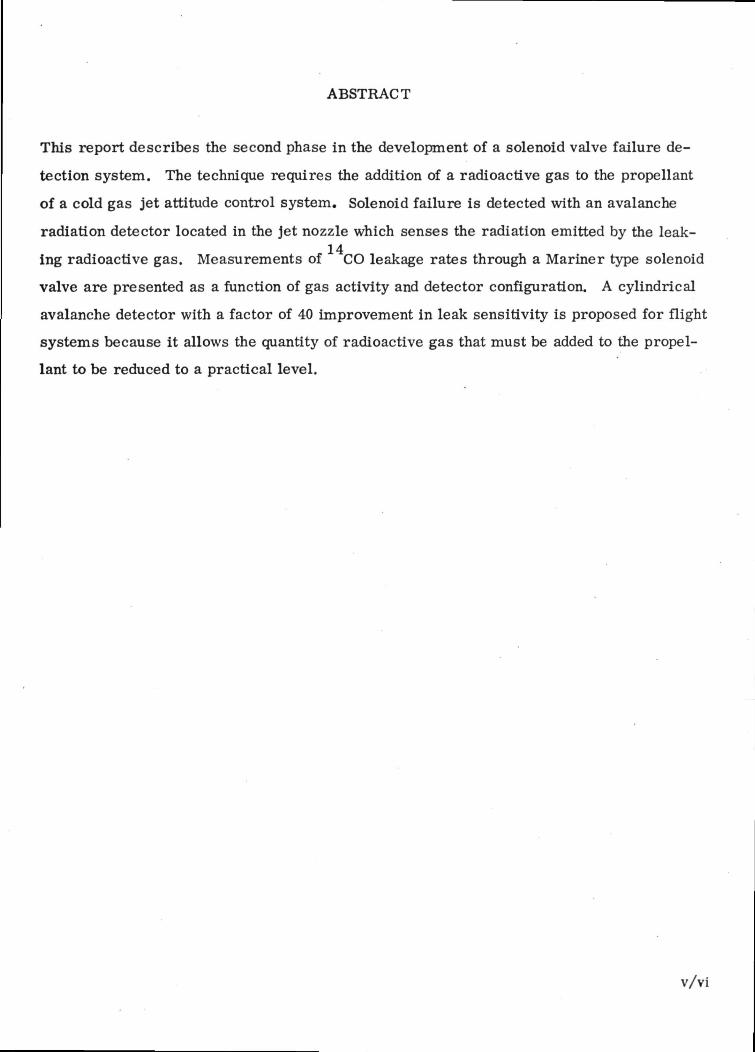
ABSTRACT
This report describes the second phase in the development of a solenoid valve failure de-
tection system. The technique requires the addition of a radioactive gas to the propellant
of a cold gas jet attitude control system. Solenoid failure is detected with an avalanche
radiation detector located in the jet nozzle which senses the radiation emitted by the leak-14ing radioactive gas. Measurements of CO leakage rates through a Mariner type solenoid
valve are presented as a function of gas activity and detector configuration. A cylindrical
avalanche detector with a factor of 40 improvement in leak sensitivity is proposed for flight
systems because it allows the quantity of radioactive gas that must be added to the propel-
lant to be reduced to a practical level.
v/vi

SECTION 1
INTRODUCTION
The active life of a Mariner type spacecraft, in the absence of failures, is determined
by the life of the Reaction Control System, i.e., when the propellant is consumed the
spacecraft starts tumbling in space reducing the efficiency of the communication links to
the point that the spacecraft is considered lost. Loss of propellant after launch is almost
exclusively associated with the jet valves, the thrust supply elements of the Mariner-type
cold gas reaction control system, because a perfectly sealing jet valve is a technical im-
probability. Prior to launch the leak rate of each valve is quantitatively specified, how-
ever failure can occur during flight leading to propellant loss. The Mariner-type reaction
control system includes a built-in redundancy to reduce the risk of such failure. The
weight performance of this system is very poor because two propellant tanks are used;
each serving half of the thrusters with each tank containing enough propellant to compen-
sate for the torque supplied by an open valve failure. An alternate, more weight-effective
configuration has been proposed (Reference 1). In this case the two half systems are
linked to the same propellant tank through shut-off valves. As soon as an open failure oc-
curs on one of the half systems, its feed line is shut off leaving the spacecraft in control
of the other half system. This alternate system requires a failure detection system to
control the feed line valve. This report deals with a two-phase development of a solenoid
failure detection system that will allow each valve to be interrogated periodically during
flight. The program culminated with leak tests performed on Mariner type solenoid valves
with a prototype failure detection apparatus. The results of the Phase I feasibility study
will be briefly reviewed, followed by the results of a comparative analysis of avalanche
detector configurations presented relative to the design of an operational solenoid failure
detection system.
1. Roselli-Lorenzini, F. G., "Failure Detection System for Solenoid Actuated Gas JetValves, " JPL Document No. SPS 37-61, Volume HI.
1-1/2

SECTION 2
TECHNICAL DISCUSSION
In the initial phase of this program, measurements were made to determine the feasibility
of detecting gas jet leakage in flight using a radioactive gas and a GE avalanche detector,
a tiny, high gain, solid state radiation detector. In these experiments a radioactive gas14
CO was mixed with N and metered with a Vacoa metering valve through a test nozzle,2
into a vacuum chamber. The calibration of the metering valve is shown in Figure 2-1.
With the test apparatus shown in Figure 2-2, it was possible to show that the radiation14 14(beta particles) emitted by C could be detected when the CO was leaking at a rate
of a few scc/hr. It was also shown that much greater sensitivity to leak rate was obtained
when the detector was placed between the leaking valve and the nozzle as opposed to plac-
ing the detector outside the cone of the jet nozzle. At the end of the first phase of this
program then the measurements had demonstrated the feasibility of measuring the
1 scc/hr leak rates typical of solenoid failure with a radioactive gas and an avalanche
CALCULATED FROMVACOA CAL FOR He
MEASURED WITH RADIOACTIVEC1*-CO2 AND ADJVCTED FORMOLECULAR WE1CKT DIFFER-ENCE
1M MO
MCTUWC VALVE TVRN UNTTf
Figure 2-1. Metering Valve Calibration
2-1

OUTLETPRESSURE
GAUGE" 3
RADIOACTIVfINLET
/NLETPRESSURE
VACUUMCHAMBER
ION'CHAMBER
Figure 2-2. Test Apparatus Schematic
radiation detector. It was also discovered that the best approach to an in-flight system
required a tiny detector to be placed between the seat of the solenoid valve and the gas jet
nozzle. Thus, the second phase of this program began with an evaluation of several ava-
lanche detector configurations to determine which could be adapted to the problem, so that
a practical in-flight system could be developed.
2.1 DETECTOR CONFIGURATION
An avalanche detector consists of a silicon avalanche diode and its tunnel diode amplifier.
The silicon avalanche diode is a PN junction device with a "contoured" N region. This
physical shaping of the back side of the device presents a high electrical field to the incom-
ing radiation. The polarity of the field is such that each time radiation is absorbed the
electrons released from the ionized silicon atoms are accelerated, striking and ionizing
other atoms in the crystal resulting in a cascade of electrons toward the back contact of
the avalanche diode. The tunnel diode amplifier monitors this cascade of charge and trig-
gers when the number of electrons exceeds a preset level.
Of all solid state radiation detectors internal gain or amplification is only inherent in the
avalanche detector. It is this gain that prompted the use of avalanche detectors in this
application because no other device could be made small enough to fit inside a jet nozzle
2-2

14without interfering with normal gas flow and still have sufficient sensitivity to detect C14beta particles. It should be remembered that C labelled carbon monoxide was selected
as the tracer gas to be mixed with the nitrogen propellant because the CO has the same
molecular weight as N , thus they will both leak at the same rate.£t
Initially three detector configurations were evaluated as shown in Figure 2-3. The first
was the plane or wafer shaped avalanche diode which would be mounted in close proximity
to the solenoid valve seat and the aperture of the jet nozzle. The other two configurations
required developmental diodes; one an annular avalanche diode which would be mounted
where the solenoid valve "seats" with the jet nozzle. The other was a cylindrical avalanche
diode which would be mounted in the nozzle such that its active surface had the same in-
ternal dimensions as the jet nozzle.
PLANEAVAL AN CUE
DIODE
ANNULARAVALANCUE
DIODE
Figure 2-3. • Leak Detector Configurations
CYLINDRICALAVALANCUF
DIODE
Theoretically it turns out that the cylindrical diode configuration should be nearly 40 times
more sensitive to leak rate than the wafer and 10 times more sensitive than the annular14
configuration primarily because it is a 4?r detector; i.e., it can detect any C beta emitted
in any direction as it passes through the jet nozzle. Sample calculations of the leak sensi-
tivity of the plane, annular and cylindrical avalanche diodes are presented below.
2-3

SAMPLE DETECTOR SENSITIVITY CALCULATIONS
A. PLANAR CONFIGURATION
Outlet =DetectorCount Rate(0.125 in active dia)
Inlet leak Inlet Activityrate
Outlet 14,
' per unit vol. Detector Area DetectionDistance x Efficiency
4 IT to leak
1.6 x 10q d/sec (0.22) (0.2)4 IT
44 counts/sec 8 1 cc per hour
B. CYLINDRICAL CONFIGURATION
OutletDetectorCount Rate(0.100 in inside dia)
Inlet leak Inlet Activity Outletrate per unit vol. Detector Area i-*C
1 Distance Detectionto leak Efficiency
1.6 x 10⁴ d/sec (1) (0.1)
= 1600 counts/sec @ 1 cc per hour
C. ANNULAR CONFIGURATION
OutletDetectorCount Rate(I.D. 0.280 cm)(O.D. 0.460 cm)
Inlet leakrate
Inlet Activityper unit vol.
47T
OutletDetector Area ^^Carbon( D i s t a n c e * Efficiencyto leak
= 1.6 x 10* d/sec (1) (0.2)
200 c/sec
Note: Count rates are calculated independent of gas transit time through detectorssensitive volume.
2-4

During this program experimental verification of diode sensitivity could only be performed
with the plane diode configuration because both the annular and cylindrical diode configu-
rations had not advanced beyond the prototype stages of development. Near the end of this
program significant progress had been made toward developing cylindrical detectors (see
Appendix A). However, no operational devices were produced during this contract period,
as a result all experimental results pertain to the plane diode configuration.
2.2 LEAK TEST PROCEDURE
Mariner type solenoid valves were used to demonstrate the sensitivity of the solenoid
failure detection scheme. A test nozzle was designed to hold a plane avalanche diode in
proximity to the "seat" between the valve and the nozzle aperture.
A mechanical drawing of the detector's position in the test nozzle is shown in Figure 2-4.
It should be noted that the internal dimensions of the test nozzle closely approximate those
of a "Mariner" jet nozzle. The completed test nozzle avalanche detector and "Mariner"
solenoid valve are shown in Figure 2-5. This test nozzle connects to the leak test appara-
tus below the metering valve as shown in Figure 2-6. Briefly, the radioactive gas, a mix-
ture of Carbon-14 tagged carbon monoxide and nitrogen is contained in a reservoir bounded
by valves 1 through 7. With the Mariner solenoid valve open the test nozzle was evacuated
and sealed off from the vacuum pump and the gas mixture was then metered in through the
Vacoa metering valve, 7, in Figure 2-6. The count rate measured by the detector was then
tabulated as a function of leak rate and the activity of the gas. After calibrating the detector
inside the test nozzle, the Mariner solenoid valve was then closed and again the radioactive
gas was allowed to flow into the solenoid valve through the by-pass valve, 5, in Figure 2-6.
The count rate was then tabulated and the leak rate defined relative to the activity of the gas
in the reservoir. The complete test procedure is described in detail in Appendix B.
2.3 TEST RESULTS
Using the apparatus and test procedure described above, the following tests were performed:
1. The detector mounted in the test nozzle was calibrated as a function of gasactivity. The results are shown in Table 2-1.
2-5

.2N
CO<DH
iCO0)
2-6

•
Figure 2-5. Test Nozzle, Detector and Solenoid Valve
VACOA
AVAL/QMCWEDETECTOR
®8
i to iMOZZLE
D* /OUTLETVALAHCDETZCTOX
STORAGEBOTTLE
/OH
Figure 2-6. Leak Test Apparatus
2-7

2. The detector mounted in the test nozzle was also calibrated as a function offlow rate, metering valve turns units (Table 2-2).
3. The solenoid valve leak rate was measured with the calibrated detector asshown in Table 2-3.
4. Tests were performed to determine the feasibility of recirculating theradioactive gas mixture.
Table 2-1. Effect of Diluting Radioactive Gas
MeteringValveSetting(units)
200
InletPressure
(psi)
15
5.0
5.0
InletDetector
CountRate
(counts/sec)
1100120011001030
120108115110105
2529312528
GasActivity
(microcuries/cm3)
50
2
0.08
OutletPressure(mm Hg)
10
OutletDetector
CountRate
(counts/10 sec)
270265279280
2522272529
23132
2-8

The gas dilution results in Table 2-1 were obtained by increasing the total volume of the3
gas mixing reservoir up to 300 cm and letting air in which reduced the number of micro-1 A Q
curies of C per cm of air. In this way it was possible to detect less than 0. 1 micro-
curies C/cm .
The detector calibration data of Table 2-2 indicated that count rate dropped off at the higher
leak rates. This seems likely in view of the fact that the probability of detecting the radio-
active molecules of the gas is less likely when they are rapidly moving past the sensitive
volume than when they are dwelling in it for longer periods.
It is important to note here that the use of cylindrical detectors should reduce the effect of
flow rate on detection sensitivity because, the radioactive gas will dwell within the sensi-
tive volume of the cylindrical device longer thus increasing the probability of detecting it.
For example the following relationship
t f =^ (3.6X10 3 )
3gives the time t (sec) it takes for a gas flowing at rate Q (cm /hr) to flow through cylinder
oI centimeters long and active area A (cm ). Using this it can be seen that a cylinder 0.1
cm long and 0. 25 cm inside diameter has a dwell time of several seconds at a flow rate of
1 cm3/hr.
The leak rate data of Table 2-3 obtained with Mariner solenoid valve #2 shows considerable
repeatability within the statistical error of the measurement. As shown in Figure 2-7, the
average values of these data fall on the detector calibration curve between 3 and 5 cc/hr.
The corresponding JPL calibration was 4 cc/hr.
The remaining data shown in Table 2-4 was taken to evaluate the feasibility of transferring
the gas that had leaked from the reservoir through the metering valve, through the solenoid
valve, into the test chamber by returning it to the reservoir via a piston type recirculating
pump. The data of Table 2-4 was taken with a Toepler pump which uses a mercury piston
2-9

Table 2-2. Outlet Detector Calibration Tests versus Leak Rate (Metering Valve Turns)
Timehrs
1040
1044
1049
1054
1059
1104
1109
1113
1117
MeteringValveSetting
0
200
200
LeakRatescc/hr
0
7.2
7.2
InletPressurepsi
5.6
5.58
5.56
5.54
5.52
5.50
5.48
InletDetectorcount/Ratecount/lOsec
IonChamberCurrentamps
TEST 13522489484472
504534457493
481469489511
498490519497
483463484484
450558472492
485469470489
472544488515
460495457482
4xlO~9
3.9xlO~9
OutletPressuremm Hg
7
8
9
10
11
12
13
14
15
OutletDetectorCount Ratecount/10 sec
0
3315
4745
6844
3754
2361
553
11
2376
8565
2-10

Table 2-2. Outlet Detector Calibration Tests versus Leak Rate(Metering Valve Turns) (Cont'd)
Timehrs
1121
1125
1150
1160
MeteringValveSetting
0
0
(Seconds)
0
105
220
330
430
540
660
0
195
195
LeakRatescc/hr
0
0
5.4
5.4
InletPressurepsi
5.46
5.45
InletDetectorcount/Ratecount/lOsec
435491462450
496504457493
RECIRCULATION
5.60
11.7
11.65
11.60
11.60
490489500465
IonChamberCurrentamps
3.9xlO~9
4.0xl0^9
TEST 14
225220238255
230240229250
240235228250
249249236240
268228238250
245255238229
236250236240
8.6X10"11
8.55
8.5
OutletPressuremm Hg
16
17
5
9
10
11
12
13
14
15
OutletDetectorCount Ratecount/10 sec
6654
4575
0000
0000
1375
7124
1115
313
5715
39
137
311
53
2-11

Table 2-2. Outlet Detector Calibration Tests versus Leak Rate(Metering Valve Turns) (Cont'd)
Timehrs
NO RE
0
39
79
116
151
191
MeteringValveSetting
CYCLE P
0
200
NO RECYCLE
0
42
84
122
162
200
240
0
225
LeakRatescc/hr
InletPressurepsi
UMPED OUT TEST ]
7.2
PUMPED
18.0
11.60
11.55
11.50
11.45
11.40
11.35
OUT TEST
11.35
11.30(Extrapolated)
11.25
11.20
11.15
11.10
11.05
InletDetectorcount/Ratecount/10 sec
NOZZLE
265245260241
250248260239
250240275242
240238261245
248246254239
254250251240
NOZZLE
250248239240
240235
229254
250242
234240
239240
229238
IonChamberCurrentamps
8.5
8.45
8.4
8.4
8.3
8.2
8.1
OutletPressuremm Hg
10
11
12
13
14
15
8.5
10
11
12
13
14
15
OutletDetectorCount Ratecount/10 sec
0000
5956
11755
3974
13957
5576
0000
53
73
45
31
33
35
2-12

Table 2-2. Outlet Detector Calibration Tests versus Leak Rate(Metering Valve Turns) (Cont'd)
Timehrs
NO RE
0
21
40
59
78
97
116
MeteringValveSetting
CYCLE -
0
250(Ex1
250
LeakRatescc/hr
PUMPED
40irapola
InletPressurepsi
OUT TEST
11.05
ted)
10.90
10.70
ION CHAMBER
4.:39 x 10~1:
InletDetectorcount/Ratecount/lOsec
NOZZLE
229
235220
240220
235230
231250
230225
228235
CALIBRATION
' amps/micro
IonChamberCurrentamps
8.1
7.9
7.7
curie
OutletPressuremm Hg
9
10
11
12
13
14
15
OutletDetectorCount Ratecount/10 sec
0
35
33
35
32
55
76
2-13

Table 2-3. Solenoid Valve #2 Leak Test
Time
hrs.
1105
1120
1135
1150
1330
1345
1400
1415
1430
1445
1500
MeteringValveSetting
0
Bypassed
RECYCLED
0
Bypassed
RECYCLED
InletPressure
psi
10.7
10.7
InletDetector
Count Ratecount/lOsec
220210198224190
210198195225221
225195190221220
221225198215202
210221195219208
219195201198210
198190210225195
210210218298190
201225198190225
IonChamberCurrent
amps
7.7X10'11
7.7xlO~1;L
OutletPressure
mm Hg
10.4
10.6
10.4
OutletDetectorCount Ratecounts/10 sec
00000
10010
13011
11310
00000
10101
01101
1101113110
2-14

oO<n
S
14
12
10
- TEST SOLENOID NO. 2
GAS ACTIVITY0.2 MICROCURIES/CM3
I2 3 4 5 6 7 8
SOLENOID LEAK DETECTOR COUNT RATE (COUNTS/10 SEC)
10
BACKGROUND
Figure 2-7. Leak Test Results Solenoid Valve No. 2
and float valves to open and close the input and output to the piston chamber. The data
clearly indicates the feasibility of this pumping scheme because it was possible to restore
the original conditions within a few minutes after each test as long as there was no leakage
around the joints and valves of the apparatus.
2-15

Table 2-4. Vacuum System Stability and Recycle Tests
A. Stability test performed with all external valves closed afterevacuation
TimeInlet(psi)
1100
1200
1330
1500
1700
Recycled 10 times-
B. Recycling test
RecycleNumber
0.15
Initial
After bleed in
After 1st cycle
2nd
3rd
4th
5th
6th
0.15
Inlet(psi)
1.2
0.2
0.4
0.6
0.8
1.0
1.1
1.2
PressureOutlet(mm Hg)
12.3
15.0
18.9
22.9
27.3
7.5
Outlet(mm Hg)
3.0
25.0
15.0
10.0
8.0
6.0
5.0
3.0
2-16

SECTION 3
CONCLUSIONS AND RECOMMENDATIONS
The test results showed that an avalanche detector could be placed in a jet nozzle and
have sufficient sensitivity to detect leak rates typical of the Mariner type solenoid valves
used in these tests. The accuracy and precision of the measurements have improved con-
siderably over the first feasibility tests carried out in this program. Based on these re-
sults the configuration recommended for an operational solenoid failure detection system
should be the cylindrical detector because of the factor of 40 improvement in sensitivity.
This would require less radioactive gas to be added to the propellant reservoir and would
improve the precision and accuracy of the measurement considerably. It was also shown
that ground testing of solenoid leakage could be performed practically by incorporating a
recirculating pump; however, it is recommended that the apparatus use welded joints as
opposed to the use of fittings.
3-1/2

APPENDIX A
CYLINDRICAL AVALANCHE DETECTORS
The actual fabrication of cylindrical type detectors for internal gas counting requires
the development of several additional process steps not needed for normal plane detec-
tors. It is extremely important that the silicon surface damage be kept to a minimum
during the various drilling, lapping and etching operations.
The starting material for a cylindrical detector is, typically, a 50 ohm-cm silicon slug,
3/8" long, cut from a 1/4" diameter rod grown in the (111) direction. This slug is
drilled out along its axis, to a diameter of 1/8".
Several different methods are being investigated for making the axial hole in the slug:
lapping, ultrasonic drilling, diamond core drilling, and combinations of these techniques.
The basic requirement is that a maximum damage region of 1 mil (0. 001") is allowed on
the inner surface of the hole.
The hollow slug is subjected to a deep gallium diffusion ( ~ 3. 8 mil junction depth). After
diffusion, the outer surface is lapped to remove the diffused region, and the ends of the
cylinder are lapped with a conical lapping tool to achieve the required surface contouring
angle. When all lapping operations are completed, the device is cleaned and etched to
remove all damage regions (1 mil is etched off).
Mechanical mounting of the detector will depend on the specific application. A typical
mounting for a gas (or liquid) flow detector is shown schematically in Figure A-l. The
detector is mounted onto a tube at each end, using conductive silver epoxy to assure a good
electrical contact to the p-region of the detector. The gas or liquid to be counted flows in
through one tube and out the other. The entire detector assembly can be encapsulated, the
exact configuration depending on the location and space available.
A-l

RTV RUBBER
SILVEREPOXY
P-/V JUNCT/OW
P-
\\\\\\\\\\\\
t— GROUNDFigure A-l. Flow Detector Schematic
VOLTAGE
Two slugs of silicon have been drilled out, diffused and lapped. The drilling was done
by an ultrasonic process. One of the cylinders cracked during the contouring process.
The other was contoured at a 45 bevel angle and subsequently etched which is shown in
Figure A-2. The contouring angle was shown to be too large by electrical tests, and a
recontouring is being performed. Additional silicon slugs are being prepared for drilling
and diffusion. Several different drilling methods are being studied, and successful use
has been made of ultrasonic drilling and of lapping. Diamond core drilling will also be
evaluated.
A-2

- .--,.-. . . . .
- . - ^ -:-. • ^.••••.'r*^•••-••\v~: v^-"-- '*•-*"*€*.
-.
• . ,_,
Figure A-2. Initial Cylindrical Diode Configuration
A-3/4

APPENDIX B
OPERATING INSTRUCTIONS FOR THESOLENOID VALVE LEAK TEST APPARATUS
1. Assemble system according to Figure 2-6 in the text.
2. Make sure all valves are closed before turning on roughing pump.
3. Open all valves and evacuate entire system including both upper and lowerhalves of Toepler pump (be sure bleed valve on Toepler pump controller isclosed).
4. When system is evacuated close all valves again and open valve #1. The radio-active gas will then transfer into the section bounded by valves #1 through #7(see Figure B-l.a).
Test Nozzle Calibration
5. Turn on avalanche detector counting system which monitors test nozzle detec-tor count rate. Turn discriminator knob clockwise until continuous counts areobtained on the display, then turn the discriminator knob back one-quarter turn.Repeat this procedure with the avalanche gain control knob. This maximizesthe sensitivity of the unit.
6. Energize the solenoid #8, then turn the metering valve, #7, (see Figure B-l.b)and tabulate detector count rate versus metering valve setting. This calibratesthe test nozzle detector according to the metering valve calibration as shown inSection 2, Figure 2-1.
7. After calibration, close #7.
8. Turn off roughing pump. Open Toepler pump controller bleed valve carefullyand leave it open. The mercury piston will begin to fill the upper chamber ofthe pump (Figure B-l.c) forcing the radioactive gas through the outlet tube backinto the storage line. When the mercury reaches the top contact the relay inthe controller will start the roughing pump again which draws the mercuryback down into the lower chamber (See Figure B-4. d).When the mercury touchesthe lower contact points the controller shuts off the roughing pump again causingthe piston to force more radioactive gas through the outlet. In practice thisprocess continued automatically as long as the pressure in the storage linedidn't exceed 8 psi. Normally about 10 cycles were required to force the gasback into the storage line.
9. De-energize the test solenoid valve and with the electronic counter bias controlsset the same as for the nozzle calibration, open valve ?5 and monitor count rateversus time.
10. After the leak test close #5 and recycle the radioactive gas. B_l

Figure B-l. Solenoid Valve Leak Test Apparatus
r
a.
, <1:,
•
B-2
b.

coo,
CO
art
Icx
CO
j/^cte—fs £ 1|/vV
• - • • ' • " ^
-
0)(-(
S) -v .**--̂ *!*
••• • * - /
-
B-3/4