dlp using digital micromirror devices: a primer - spiespie.org/samples/sl24.pdf1 overview digital...
TRANSCRIPT

1 Overview
Digital Light Processing (DLP®) is known as a multipurpose, robust, modern,and easily accessible optical technology that uses digital micromirror devices(DMDs), which reflect light pixelwise from a light source to a target. DLP®
was invented by Texas Instruments and is commonly used in projectors, asshown in Fig. 1, but is also used in other fields.
The internal structure of a DMD is visible in Fig. 2. Many reflective micro-mirrors are placed in an array. Each micromirror represents an optical pixel(Fig. 3). Depending on the format (there are different formats available) of theDMD, the array has a number of micrometers placed on it, e.g., 768 × 1024(XGA) or 1920× 1080 (FullHD 1080p).
To protect the micromirrors from external influences, a cover glass is installedon the aperture. The DMD is, in most cases, deliverable as a UV-, VIS-, or IR-optimized version, depending on the field of application.
Figure 1 BENQ DLP® projector. Image courtesy of Sign-Tronic AG.
Figure 2 XGA DMD on a mounting plate. Image courtesy of Sign-Tronic AG.
Figure 3 Micromirrors on a XGA DMD 35x magnification. Image courtesy of Sign-Tronic AG.
Gmünder: DLP® Using Digital Micromirror Devices 1
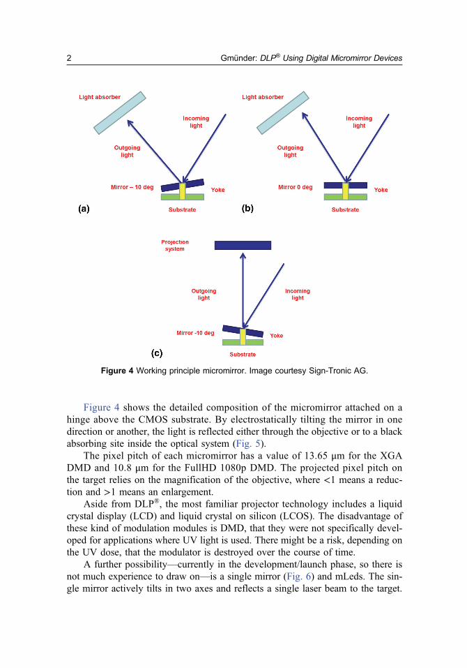
Figure 4 shows the detailed composition of the micromirror attached on ahinge above the CMOS substrate. By electrostatically tilting the mirror in onedirection or another, the light is reflected either through the objective or to a blackabsorbing site inside the optical system (Fig. 5).
The pixel pitch of each micromirror has a value of 13.65 μm for the XGADMD and 10.8 μm for the FullHD 1080p DMD. The projected pixel pitch onthe target relies on the magnification of the objective, where <1 means a reduc-tion and >1 means an enlargement.
Aside from DLP®, the most familiar projector technology includes a liquidcrystal display (LCD) and liquid crystal on silicon (LCOS). The disadvantage ofthese kind of modulation modules is DMD, that they were not specifically devel-oped for applications where UV light is used. There might be a risk, depending onthe UV dose, that the modulator is destroyed over the course of time.
A further possibility—currently in the development/launch phase, so there isnot much experience to draw on—is a single mirror (Fig. 6) and mLeds. The sin-gle mirror actively tilts in two axes and reflects a single laser beam to the target.
Figure 4 Working principle micromirror. Image courtesy Sign-Tronic AG.
Gmünder: DLP® Using Digital Micromirror Devices2

An mLed is an array of microlight emitting diodes (LEDs), which can be con-trolled pixel by pixel.
By evaluating all of these projection technologies, the conclusion is thatDLP® technology unites these positive factors:
l Robustness to different wavelengths (UV–VIS–IR) and power levels,l Well-known and accepted technology on the market,l Low price and low maintenance/operation costs,l High-exposure speed with large resolution (depending on the light source
and the objective), andl Broad range of different form factors.
These points are the reasons that DLP® can be used for many fields of appli-cation, such as computer lithography, 3-D printing, and spectroscopy.
Figure 5 Components of an optical engine. Image courtesy of Sign-Tronic AG.
Figure 6 Hamamatsu MEMS mirror. Image courtesy of Hamamatsu Photonics.1
Gmünder: DLP® Using Digital Micromirror Devices 3