dls 6600 series - spirent · 4.5 device dependent commands ... the “dls 6600 series” includes...
TRANSCRIPT
Operating Manual
DLS 6600 SeriesADSL2++ Production Tester
Version 1April 2004


DLS 6600 Operating Manual
Spirent Communications - Table of Contents Page 17104000552 04/04 -1
Table of Contents
1. INTRODUCTION ............................................................................................. 1-11.1 About Spirent’s Involvement in Wireline Simulation ....................................... 1-11.1 About the DLS 6600 ADSL2++ Production Tester ........................................... 1-11.2 About this Manual ............................................................................................. 1-2
2. GETTING STARTED ...................................................................................... 2-12.1 Receiving and Unpacking the Unit .................................................................... 2-12.2 Setup Overview ................................................................................................. 2-12.3 Cabling Requirements ....................................................................................... 2-22.4 Front Panel Components and Connections ........................................................ 2-2
2.4.1 Reading Remote and Power Status ............................................................. 2-22.4.2 Connecting to Analog Devices with RJ-45 Connectors
(Front and Rear Panel) ............................................................................. 2-32.4.3 Setting the Reach with Push buttons ........................................................... 2-3
2.5 Back Panel Components and Connections ........................................................ 2-32.5.1 Connecting to Power ................................................................................... 2-42.5.2 Connecting to Analog Devices with CF Connectors .................................. 2-42.5.3 Connecting to Analog Devices with Two-pole Terminal Strips .................. 2-42.5.4 Connecting to a Windows Computer (for Remote Control) ........................ 2-5
2.5.4.1 Connecting the Computer via the Serial Port (RS-232) ................................. 2-52.5.4.2 Connecting the Computer via the IEEE 488 Port (GPIB) .............................. 2-5
3. CONTROL SOFTWARE ............................................................................... 3-13.1 About the Software ............................................................................................ 3-1
3.1.1 Computer Hardware and Software Requirements ....................................... 3-13.2 Installing the Software ....................................................................................... 3-1
3.2.2 Accessing the Main Window ....................................................................... 3-23.2.3 Accessing the Control Window (s) .............................................................. 3-23.2.1 Identifying Simulator Connection ............................................................... 3-33.2.2 Setting the Control (Manual or Remote) of Length Settings ....................... 3-4
3.3 Configuring the DLS 6600 ................................................................................ 3-43.3.3 Reading the Cable Gauge ........................................................................... 3-43.3.4 Configuring the Length of the Cable ........................................................... 3-5
4. REMOTE CONTROL ..................................................................................... 4-14.1 IEEE 488 Interface ............................................................................................ 4-1
4.1.1 IEEE 488.1 Interface Functions Supported ................................................ 4-14.1.2 IEEE 488 Address ....................................................................................... 4-14.1.3 The Service Request (SRQ) Line ................................................................. 4-24.1.4 Resetting the DLS 6600 ............................................................................... 4-24.1.5 Message Terminators .................................................................................. 4-34.1.6 Example using the IEEE 488 Interface ....................................................... 4-3
4.2 RS-232 Serial Interface ...................................................................................... 4-44.2.1 Message Terminators .................................................................................. 4-44.2.2 Example using the RS–232 Interface .......................................................... 4-4
4.3 Data formats ....................................................................................................... 4-54.4 Command Syntax .............................................................................................. 4-54.5 Device Dependent Commands .......................................................................... 4-6
4.5.1 :SETting:CHANnel:LENGTH <Length> ................................................... 4-74.5.2 :SYStem:KLock ON/OFF ............................................................................ 4-7
DLS 6600 Operating Manual
Table of Contents Page 2- Spirent Communications
7104000552 04/04 -1
4.5.3 :SYStem:COMMunicate:SERrial:PACE <pace> ....................................... 4-74.6 Common Command Set ..................................................................................... 4-84.7 Status Reporting ............................................................................................... 4-12
4.7.1 Status Byte Register (STB) ........................................................................ 4-124.7.2 Event Status Register (ESR) ...................................................................... 4-124.7.3 DLS 6600 Synchronization ........................................................................ 4-13
5. TROUBLE SHOOTING ................................................................................. 5-1
6. REFERENCES ................................................................................................... 6-1
7. CUSTOMER SUPPORT ................................................................................ 7-17.1 Customer Service Contact Information ............................................................. 7-17.2 Protecting Your Investment ............................................................................... 7-1
8. WARRANTY ....................................................................................................... 8-1
9. SHIPPING THE UNIT .................................................................................... 9-1
10. SPECIFICATIONS ....................................................................................... 10-110.1 General ........................................................................................................... 10-110.2 Included: ........................................................................................................ 10-1
11. SAFETY ............................................................................................................ 11-111.1 Information .................................................................................................... 11-1
11.1.1 Protective Grounding (Earthing) ............................................................ 11-111.1.2 Before Operating the Unit ....................................................................... 11-111.1.3 Power Supply Requirements ................................................................... 11-111.1.4 Fuse Configuration ................................................................................. 11-111.1.5 Connections to a Power Supply .............................................................. 11-111.1.6 Operating Environment ........................................................................... 11-111.1.7 Class of Equipment ................................................................................. 11-2
11.2 Instructions ..................................................................................................... 11-211.2.1 Before Operating the Unit ....................................................................... 11-211.2.2 Operating the Unit .................................................................................. 11-2
11.3 Symbols ......................................................................................................... 11-3
APPENDIX A. MEASUREMENTS AND TEST RESULTS ............... A-1A.1 Measurement of the DLS 6600 ........................................................................ A-1A.2 Common Errors ................................................................................................ A-1A.3 Electrical Characteristics Test Results ............................................................. A-2
APPENDIX B. BACKGROUND NOISE MEASUREMENT CONSIDERATIONS .............................................................................................B-1

DLS 6600 Operating Manual
Spirent Communications - Page 1-1
7104000552 04/04 -1
1. INTRODUCTION
1.1 About Spirent’s Involvement in Wireline SimulationThank you for choosing Spirent Communications.
Spirent Communications has been in the wireline simulation business for over 15 years. Since the days ofthe S2, Spirent Communications has designed many new simulators both to customers' specifications and toconform to an ever-growing range of standards.
The DLS 6600 VDSL Production Tester has been designed to meet the needs of very high volume manufac-turers of ADSL2++ bandwidth access products (DC to 4.5 MHz). The DLS 6600 is used to ensure xDSLcopper access products perform correctly before they leave the production floor. The DLS 6600 achieves alow cost per port by offering a fixed 1-port configuration, reach and line simulation tailored for this applica-tion.
1.1 About the DLS 6600 ADSL2++ Production TesterThe DLS 6600 ADSL2++ Production Tester simulates the insertion and return loss of a twisted coppercable, sometimes called wireline.
The “DLS 6600 Series” includes the DLS 6624 (24AWG), the DLS 6626 (26AWG) and the DLS 6604(PE04), and will be referred to as the “DLS 6600” within this unless otherwise stated. Specifications for the3 cable types simulated have been derived from North American (ANSI) North American (ANSI) and ETSIstandards.
Figure 1.1 DLS 6600 VDSL Wireline Simulator
The DLS 6600 ADSL2++ Production Tester simulates a 24 AWG, 26 AWG or 0.4 mm PE cable forADSL2++/ADSL2+/ADSL2/ADSL production and verification testing. The DLS 6626 is the first of thethree models to be released, has a reach of up to 23.5 kft (in 250 ft increments) and a bandwidth of DC to4.5 MHz. The unit is fully bi-directional, with all cable characteristics being accurately simulated using pas-sive components.
The DLS 6600’s front panel interface can be connected to up to two external test devices for testing a varietyof local loop products such as modems and drivers. The simulated wireline lengths can be controlled manu-ally with front panel push buttons or remotely with the control software.
The DLS 6600 Software configures and controls the DLS 6600 ADSL2++ Production Tester remotelythrough the IEEE 488 or RS-232 interfaces. The software runs on any WindowsTM 98, NT with service pack4.0 or 2000 service pack 1.0 compatible computer. The IEEE 488 and RS-232 interfaces allow the easy inte-gration of these wireline simulators into a larger test system. You can also control the DLS 6600 ADSL2++Production Tester with scripts using SCPI commands.
For customers with existing DLS 6100M or DLS 6100R based testing platforms, cost effective upgrade pro-grams to a DLS 6626 are available. Please contact your Spirent representative for further information.
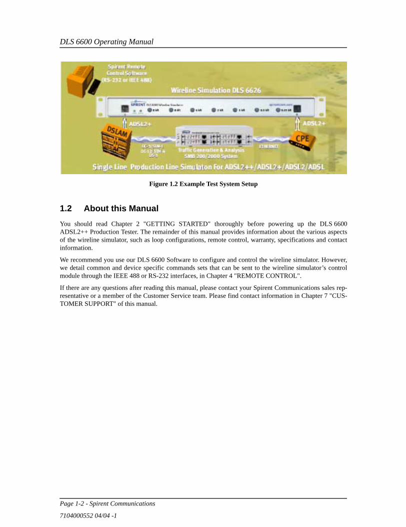
Figure 1.2 illustrates an example of a typical test setup using the DLS 6600 ADSL2++ Production Tester.
DLS 6600 Operating Manual
Page 1-2 - Spirent Communications
7104000552 04/04 -1
Figure 1.2 Example Test System Setup
1.2 About this ManualYou should read Chapter 2 "GETTING STARTED" thoroughly before powering up the DLS 6600ADSL2++ Production Tester. The remainder of this manual provides information about the various aspectsof the wireline simulator, such as loop configurations, remote control, warranty, specifications and contactinformation.
We recommend you use our DLS 6600 Software to configure and control the wireline simulator. However,we detail common and device specific commands sets that can be sent to the wireline simulator’s controlmodule through the IEEE 488 or RS-232 interfaces, in Chapter 4 "REMOTE CONTROL".
If there are any questions after reading this manual, please contact your Spirent Communications sales rep-resentative or a member of the Customer Service team. Please find contact information in Chapter 7 "CUS-TOMER SUPPORT" of this manual.

DLS 6600 Operating Manual
Spirent Communications - Page 2-1
7104000552 04/04 -1
2. GETTING STARTED
This chapter provides basic instructions on the setup of a DLS 6600 ADSL2++ Production Tester.
2.1 Receiving and Unpacking the UnitEach DLS 6600 chassis has been shipped in a reinforced shipping container. Please retain this container incase you need to ship the wireline simulator to another location or for repair. The DLS 6600 system containsthe following:
• DLS 6600 Series chassis
• 1 AC to DC wall plug-in adapter
• 1 RS–232C inter-connection cable
• 1 IEEE 488 inter-connection cable
• 1 DLS 6600 CD (software and related documents)
• 1 Operating Manual
Check that you have received all the items on the list and report any discrepancies to Spirent Communica-tions. See Chapter 9 "SHIPPING THE UNIT" for information.
2.2 Setup OverviewTo test:
1) Connect the power cord on the back of the DLS 6600 chassis and switch the power on.2) Connect a cable (either the serial or the IEEE cable) from the control computer to the back of the
DLS 6600.3) Connect your digital subscriber line access multiplexer (DSLAM) equipment to the port A on the
front of the DLS 6600.4) Connect your customer premise equipment (CPE) equipment to the port B on the front of the
DLS 6600.5) If the Key Lock feature is OFF, you can manually adjust wireline lengths by depressing the push
buttons labelled with the desired length. If the Key Lock feature is ON, you can only set the wire-line length with the remote control software.
6) Start the DLS 6600 Software.7) Connect the control software to the DLS 6600 by selecting the Start Online button in the main
window. This allows the program to poll for any connected devices over the serial or IEEE 488 interfaces and display the appropriate control dialog box for the unit’s settings.
8) Adjust the line lengths for the test loop.9) Begin testing.
See the following sections for detailed information.

DLS 6600 Operating Manual
Page 2-2 - Spirent Communications
7104000552 04/04 -1
2.3 Cabling Requirements
Cabling, switches and other equipment are needed to connect the DSLAM, the loop simulator, the noise gen-erator and the CPE. Cables should be kept as short as possible so minimum noise is coupled into the cables.Recommended cables are the CAT5 UTP. Since the length is typically short (e.g., 2 feet), this does not affectmeasurements.
Computer screen and power supplies radiate in ADSL frequency bands. This noise may be generated byeither internal or external power supplies. When the pick up noise levels are greater than -140 dBm /Hz, theywill limit the ADSL performance and influence the test results. These devices should be placed at a distancefrom the test setup or even switched off.
The interconnection wiring for Ports A and B, on the front panel, should be physically separated as crosstalkcan occur between cabling. Configure the cables so that they are not touching and the cable connecting tothe DSLAM and CPE are separated as much as possible (at least 15 cm).
2.4 Front Panel Components and ConnectionsThe connections on the front panel are used for connecting devices under test (DUT) and reading the powerand remote status. Figure 2.1 displays the key components of the front panel.l
Figure 2.1 DLS 6600 Front Panel
DLS 6600 Front Panel Components
1. Port A balanced RJ-45 connector: used to connect a DUT2. Port B balanced RJ-45 connector: used to connect a DUT
3. Remote LED: indicates the remote status
4. Power LED: indicates the power status
5. Length Setting Push Buttons: for manual control of wireline simulation length
2.4.1 Reading Remote and Power StatusThe DLS 6600 chassis has 2 LEDs which indicate the power and remote status.
The POWER LED turns green when the power is turned on. The power LED blinks red if it fails its self-test,or solid red if it detects an internal error.
The REMOTE LED is off after a power-up or a reset. When the unit receives the first remote message, theREMOTE LED turns green if the command is valid or turns red if an error is detected. An invalid commandor an out-of-range value will cause an error. The REMOTE LED stays red until the error flags are cleared(see the command *ESR? for more details). When the REMOTE LED is red, the unit can still communicateas normal, but you should investigate why the error occurred. Chapter 4 "REMOTE CONTROL" showsexamples on how to read the ESR register, clear the error flags and make the REMOTE LED green onceerror conditions have been resolved.
DLS 6600
A B
8 kft 8 kft 0.5 kft4 kft 0.25 kftWireline Simulator
POWER REMOTE
2 kft 1 kftspirentcom.com
1 2
34 5
DLS 6600 Operating Manual
Spirent Communications - Page 2-3
7104000552 04/04 -1
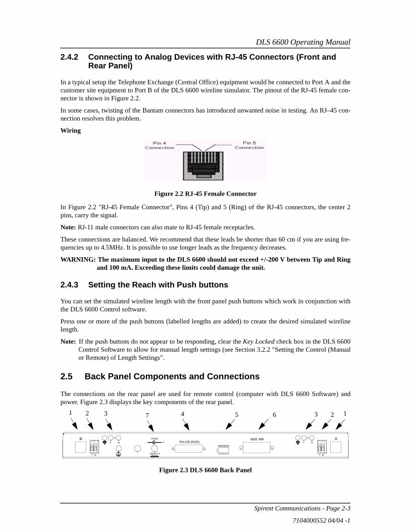
2.4.2 Connecting to Analog Devices with RJ-45 Connectors (Front and Rear Panel)
In a typical setup the Telephone Exchange (Central Office) equipment would be connected to Port A and thecustomer site equipment to Port B of the DLS 6600 wireline simulator. The pinout of the RJ-45 female con-nector is shown in Figure 2.2.
In some cases, twisting of the Bantam connectors has introduced unwanted noise in testing. An RJ–45 con-nection resolves this problem.
Wiring
Figure 2.2 RJ-45 Female Connector
In Figure 2.2 "RJ-45 Female Connector", Pins 4 (Tip) and 5 (Ring) of the RJ-45 connectors, the center 2pins, carry the signal.
Note: RJ-11 male connectors can also mate to RJ-45 female receptacles.
These connections are balanced. We recommend that these leads be shorter than 60 cm if you are using fre-quencies up to 4.5MHz. It is possible to use longer leads as the frequency decreases.
WARNING: The maximum input to the DLS 6600 should not exceed +/-200 V between Tip and Ringand 100 mA. Exceeding these limits could damage the unit.
2.4.3 Setting the Reach with Push buttons
You can set the simulated wireline length with the front panel push buttons which work in conjunction withthe DLS 6600 Control software.
Press one or more of the push buttons (labelled lengths are added) to create the desired simulated wirelinelength.
Note: If the push buttons do not appear to be responding, clear the Key Locked check box in the DLS 6600Control Software to allow for manual length settings (see Section 3.2.2 "Setting the Control (Manualor Remote) of Length Settings".
2.5 Back Panel Components and Connections
The connections on the rear panel are used for remote control (computer with DLS 6600 Software) andpower. Figure 2.3 displays the key components of the rear panel.
Figure 2.3 DLS 6600 Back Panel
A4 A3 A2 A1 A0
10
ADDRESS
IEEE 488RS-232 (DCE)
9V D.C.300mA max
POWERB AT R
T R
T R
RT
- +
1 2 3 7 4 5 6 3 2 1
DLS 6600 Operating Manual
Page 2-4 - Spirent Communications
7104000552 04/04 -1
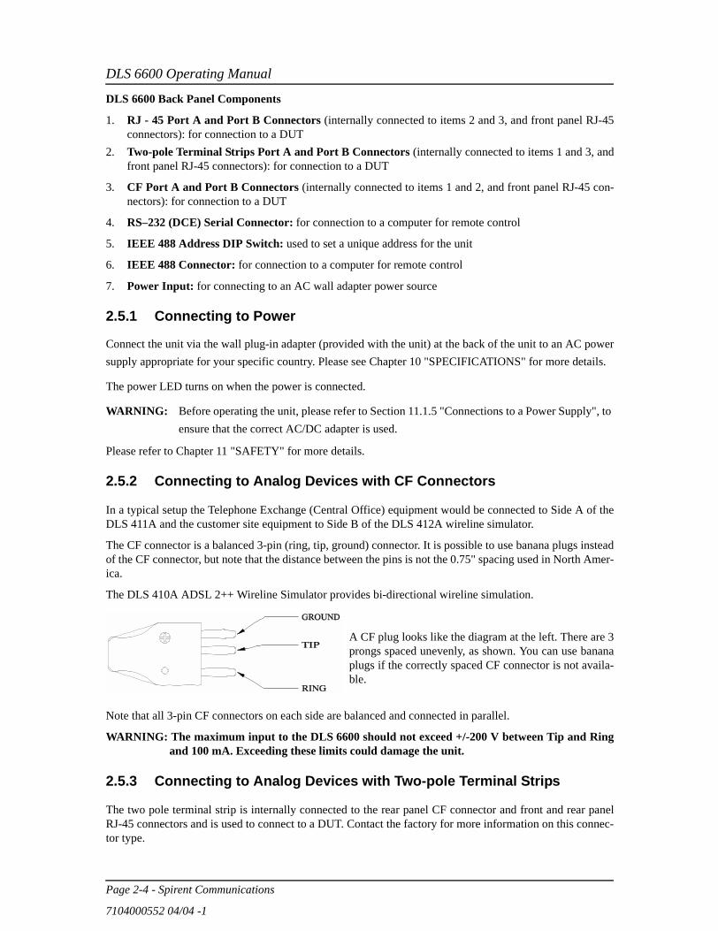
DLS 6600 Back Panel Components
1. RJ - 45 Port A and Port B Connectors (internally connected to items 2 and 3, and front panel RJ-45connectors): for connection to a DUT
2. Two-pole Terminal Strips Port A and Port B Connectors (internally connected to items 1 and 3, andfront panel RJ-45 connectors): for connection to a DUT
3. CF Port A and Port B Connectors (internally connected to items 1 and 2, and front panel RJ-45 con-nectors): for connection to a DUT
4. RS–232 (DCE) Serial Connector: for connection to a computer for remote control
5. IEEE 488 Address DIP Switch: used to set a unique address for the unit
6. IEEE 488 Connector: for connection to a computer for remote control
7. Power Input: for connecting to an AC wall adapter power source
2.5.1 Connecting to Power
Connect the unit via the wall plug-in adapter (provided with the unit) at the back of the unit to an AC powersupply appropriate for your specific country. Please see Chapter 10 "SPECIFICATIONS" for more details.
The power LED turns on when the power is connected.
WARNING: Before operating the unit, please refer to Section 11.1.5 "Connections to a Power Supply", to ensure that the correct AC/DC adapter is used.
Please refer to Chapter 11 "SAFETY" for more details.
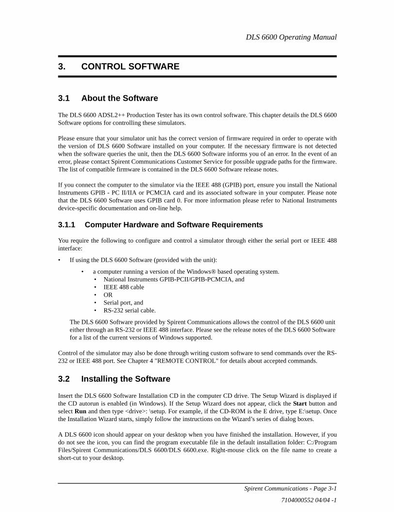
2.5.2 Connecting to Analog Devices with CF Connectors
In a typical setup the Telephone Exchange (Central Office) equipment would be connected to Side A of theDLS 411A and the customer site equipment to Side B of the DLS 412A wireline simulator.
The CF connector is a balanced 3-pin (ring, tip, ground) connector. It is possible to use banana plugs insteadof the CF connector, but note that the distance between the pins is not the 0.75" spacing used in North Amer-ica.
The DLS 410A ADSL 2++ Wireline Simulator provides bi-directional wireline simulation.
A CF plug looks like the diagram at the left. There are 3prongs spaced unevenly, as shown. You can use bananaplugs if the correctly spaced CF connector is not availa-ble.
Note that all 3-pin CF connectors on each side are balanced and connected in parallel.
WARNING: The maximum input to the DLS 6600 should not exceed +/-200 V between Tip and Ringand 100 mA. Exceeding these limits could damage the unit.
2.5.3 Connecting to Analog Devices with Two-pole Terminal Strips
The two pole terminal strip is internally connected to the rear panel CF connector and front and rear panelRJ-45 connectors and is used to connect to a DUT. Contact the factory for more information on this connec-tor type.

DLS 6600 Operating Manual
Spirent Communications - Page 2-5
7104000552 04/04 -1
2.5.4 Connecting to a Windows Computer (for Remote Control)
You configure the DLS 6600 ADSL2++ Production Tester remotely via a computer connected to either anEE 488 interface, or a serial RS-232 interface on the rear panel of the simulator. There are two options avail-able to control the DLS 6600, one being Spirent Communications’s DLS 6600 Software, or the second beingcustom software / scripting using commands sets.
The DLS 6600 Software allows you to select the simulated length of the wireline loop and whether the set-ting can be done manually (via push buttons) or remotely (with the control software). If you are developingcustom control software, refer to Chapter 4 "REMOTE CONTROL" which discusses the accepted com-mands to configure the unit.
2.5.4.1 Connecting the Computer via the Serial Port (RS-232)
Connect one end of an RS-232 serial cable to the RS-232 connector located on the back panel of theDLS 6600 chassis and the other end to a serial COM port connector on the computer.
The DLS 6600 Software can be set to connect to serial port COM1 to COM9. Make sure there is no conflictwith other serial devices.
2.5.4.2 Connecting the Computer via the IEEE 488 Port (GPIB)
The IEEE 488 portion of the control software supplied by Spirent Communications only works with aNational™ IEEE 488 interface card. If necessary, install the National™ IEEE 488 interface card in the com-puter. Please refer to the “NATIONAL INSTRUMENTS GPIB CARD AND SOFTWARE INSTALLA-TION” for information on how to install the NI card.
Connect the IEEE port on the DLS 6600 to the IEEE 488 interface card in the computer with the cable pro-vided.
No two units on the same IEEE bus can have the same IEEE 488 address. In association with the system, theDLS 6600 can use any valid IEEE 488 addresses (from 0 to 30). You can change the address by using theDIP switch on the back of the unit. For more information see Section 4.1 "IEEE 488 Interface". The weight-ing is as follows:
The following figure shows the default switch setting which is set to address 14 (i.e. 0+8+4+2+0=14) for theDLS 6600.
Table 2-1:Dip Switch Weightings
Dip Switch Weighting
AD5 16
AD4 8
AD3 4
AD2 2
AD1 1
Address 14

DLS 6600 Operating Manual
Page 2-6 - Spirent Communications
7104000552 04/04 -1
DLS 6600 Operating Manual
Spirent Communications - Page 3-1
7104000552 04/04 -1
3. CONTROL SOFTWARE
3.1 About the Software
The DLS 6600 ADSL2++ Production Tester has its own control software. This chapter details the DLS 6600Software options for controlling these simulators.
Please ensure that your simulator unit has the correct version of firmware required in order to operate withthe version of DLS 6600 Software installed on your computer. If the necessary firmware is not detectedwhen the software queries the unit, then the DLS 6600 Software informs you of an error. In the event of anerror, please contact Spirent Communications Customer Service for possible upgrade paths for the firmware.The list of compatible firmware is contained in the DLS 6600 Software release notes.
If you connect the computer to the simulator via the IEEE 488 (GPIB) port, ensure you install the NationalInstruments GPIB - PC II/IIA or PCMCIA card and its associated software in your computer. Please notethat the DLS 6600 Software uses GPIB card 0. For more information please refer to National Instrumentsdevice-specific documentation and on-line help.
3.1.1 Computer Hardware and Software Requirements
You require the following to configure and control a simulator through either the serial port or IEEE 488interface:
• If using the DLS 6600 Software (provided with the unit):
• a computer running a version of the Windows® based operating system. • National Instruments GPIB-PCII/GPIB-PCMCIA, and• IEEE 488 cable• OR• Serial port, and• RS-232 serial cable.
The DLS 6600 Software provided by Spirent Communications allows the control of the DLS 6600 unit either through an RS-232 or IEEE 488 interface. Please see the release notes of the DLS 6600 Software for a list of the current versions of Windows supported.
Control of the simulator may also be done through writing custom software to send commands over the RS-232 or IEEE 488 port. See Chapter 4 "REMOTE CONTROL" for details about accepted commands.
3.2 Installing the Software
Insert the DLS 6600 Software Installation CD in the computer CD drive. The Setup Wizard is displayed ifthe CD autorun is enabled (in Windows). If the Setup Wizard does not appear, click the Start button andselect Run and then type <drive>: \setup. For example, if the CD-ROM is the E drive, type E:\setup. Oncethe Installation Wizard starts, simply follow the instructions on the Wizard’s series of dialog boxes.
A DLS 6600 icon should appear on your desktop when you have finished the installation. However, if youdo not see the icon, you can find the program executable file in the default installation folder: C:/ProgramFiles/Spirent Communications/DLS 6600/DLS 6600.exe. Right-mouse click on the file name to create ashort-cut to your desktop.

DLS 6600 Operating Manual
Page 3-2 - Spirent Communications
7104000552 04/04 -1
3.2.2 Accessing the Main Window
The left-hand side of main window displays a supported equipment menu listing the model of simulator youcan configure. When you highlight an item in the menu, a diagram of the selected system appears on theright-hand side of the main window workspace.
To access the main window:
From the Start menu, select Programs> DLS 6600 or double-click the icon on your desktop. TheDLS 6600 Control Software window appears.
Figure 3.1 DLS 6600 Control Software - Main Window
3.2.3 Accessing the Control Window (s)
The DLS 6600 control window (s) contains the following in the workspace area:
• Loop Display window that displays the wireline gauge and length currently configured for theDLS 6600.
Note: To zoom in on either the left or right half of the loop display, double-click in that area of theLoop Display window.
• Configuration area where you set unit status and line segment length.
DLS 6600 Operating Manual
Spirent Communications - Page 3-3
7104000552 04/04 -1
To access the control window for the DLS 6600:
1) In the supported equipment menu, double-click Detect Units to have the program automatically detect supported products connected via RS-232 or the IEEE 488 communication buses (optional interface). The program automatically displays the connected units in the display area
OR
2) Click User Defined, then manually select the desired wireline simulator in the supported equip-ment menu. If you select a model of simulator not connected, the application will not execute.
Once the units are displayed on the screen, double-clicking the unit allows you to change the com-munication interface parameters.
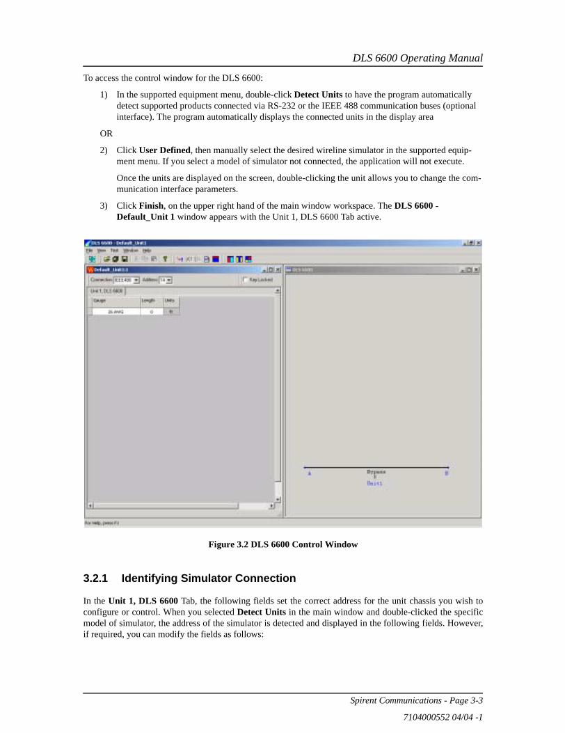
3) Click Finish, on the upper right hand of the main window workspace. The DLS 6600 - Default_Unit 1 window appears with the Unit 1, DLS 6600 Tab active.
Figure 3.2 DLS 6600 Control Window
3.2.1 Identifying Simulator Connection
In the Unit 1, DLS 6600 Tab, the following fields set the correct address for the unit chassis you wish toconfigure or control. When you selected Detect Units in the main window and double-clicked the specificmodel of simulator, the address of the simulator is detected and displayed in the following fields. However,if required, you can modify the fields as follows:

DLS 6600 Operating Manual
Page 3-4 - Spirent Communications
7104000552 04/04 -1
Connection
Click the down-arrow and select the appropriate connection type between the desired chassis and the computer from the drop down list. Your choice affects the Address/ComPort field. Your choices are: The IEEE 488, Serial or Offline mode.
Note: If you select Offline, the Address field becomes unavailable.
Address
If you selected IEEE 488 in the Connection field, click the down-arrow and select the appropriate IEEE 488 (GPIB port) address of the simulator you wish to configure from the drop down list. Your choices are: 1- 30. The default IEEE 488 address is 14.
OR
ComPort
If you selected Serial in the Connection field, click the down-arrow and select the appropriate serial port (RS-232 port) address of the simulator you wish to configure from the drop down list. Your choices are: 1- 9. The default RS-232 address is 2.
Once the correct COM Port is selected, click the Connect button on the Toolbar to use the pro-gram to control your DLS 6600. The Connect command is also found on the Test menu.
Click the Disconnect button on the Toolbar to use the program without controlling a DLS 6600 unit. This is useful for viewing the features of the program where a DLS 6600 unit is not readily available. The Disconnect command is also found on the Test menu.
3.2.2 Setting the Control (Manual or Remote) of Length Settings
The following field allows you to set the control of lengths settings to manual or both manual and remotecontrol.
Key Locked
Check the check box to ensure the wireline lengths can be controlled ONLY via the remote control soft-ware. (NOT controlled manually via the front panel push buttons). Clear the check box to allow the wireline lengths to be set manually or remotely. The default is CLEAR.
3.3 Configuring the DLS 6600
To create any of the three wireline gauge test loops, you connect the appropriate model of simulator and thenvary the length of the line segment. The simulator configures dynamically as you change values in the soft-ware.
3.3.3 Reading the Cable Gauge
When the program starts (unless Disconnect is selected), the DLS 6600 Control Software reads theDLS 6600 unit on the specified interface to find out which line is installed in the unit (DLS 6626 = 26 AWG,DLS 6624 = 24 AWG or DLS 6604 = 0.4 mm PE). The software will determine the gauge, current length,minimum, maximum, and increment lengths, and present the information on the screen. The following fieldallows you to read the simulated wireline gauge for the selected unit.

DLS 6600 Operating Manual
Spirent Communications - Page 3-5
7104000552 04/04 -1
Gauge
The possibilities are:
• DLS 6624 - the unit simulates 24 AWG gauge twisted pair wireline cable (with the lengths setin the Length field).
• DLS 6626 - the unit simulates 26 AWG gauge twisted pair wireline cable (with the lengths setin the Length field).
• DLS 6604 - the unit simulates 0.4 mm PE gauge twisted pair wireline cable (with the lengthsset in the Length field).
Note: If you view this field in Connect mode, the drop-down list displays only the connected unit gauge.
3.3.4 Configuring the Length of the Cable
The DLS 6600 configures the length of cable for all three wireline types depending on the unit you are con-nected to. The values you set in the following field is dynamically reflected in the loop diagram shown in thewindow.
Length
Click the up or down arrows to select the desired cable length or type directly in the field. Your choices are determined by the unit you are connected to:
• 26AWG in lengths of 0 ft to 23.75 kft in 250 ft increments
Regardless of the method chosen, the program will ensure that the final value is within the range of the line and will round to the nearest correct step size.
DLS 6600 Operating Manual
Page 3-6 - Spirent Communications
7104000552 04/04 -1
DLS 6600 Operating Manual
Spirent Communications - Page 4-1
7104000552 04/04 -1
4. REMOTE CONTROL
The DLS 6600 is controlled via the IEEE 488 (also known as the GPIB bus), or the RS-232 (serial) inter-face, allowing the integration of the DLS 6600 into a larger test system. The DLS 6600 remote control isdesigned with several standards in mind:
• The GPIB physical interface follows IEEE 488.1. The functions implemented are outlined in the IEEE488 Interface section.
• The Common Commands follow IEEE 488.2.
• The Device Dependent Commands (see Section 4.5) are based upon the Standard Commands for Pro-grammable Interfaces (SCPI).
• The serial port physical interface follows the EIA RS-232 standard.
The IEEE 488 and the serial interfaces are always enabled and either can be used. The DLS 6600 directs itsoutput to the last interface from which it received data. Both interfaces use the same command set and pro-duce the same results.
4.1 IEEE 488 InterfaceThis section contains information specific to the IEEE 488 interface. Section 4.2 contains the informationspecific to the RS-232 interface.
4.1.1 IEEE 488.1 Interface Functions SupportedThe IEEE 488.1 Interface functions supported by the DLS 6600 are as follows:
SH1 Source handshake - full capabilityAH1 Acceptor handshake - full capabilityT5 Basic talker - serial poll, untalk on MLAL3 Basic listener - unlisten on MTASR1 Service request - fullDC1 Device clear - fullC4 Respond to SRQE1 Open Collector driversRL1 Remote Local - full
These represent the minimum required to implement the IEEE 488.2 standard.
Note that the IEEE 488 interface is also known as the GPIB and the HP-IB interface.
4.1.2 IEEE 488 Address
The DLS 6600 can use any valid IEEE 488 address (from 0 to 31). The factory settings are:
• Address 14 for the DLS 6600
DLS 6600 Operating Manual
Page 4-2 - Spirent Communications
7104000552 04/04 -1
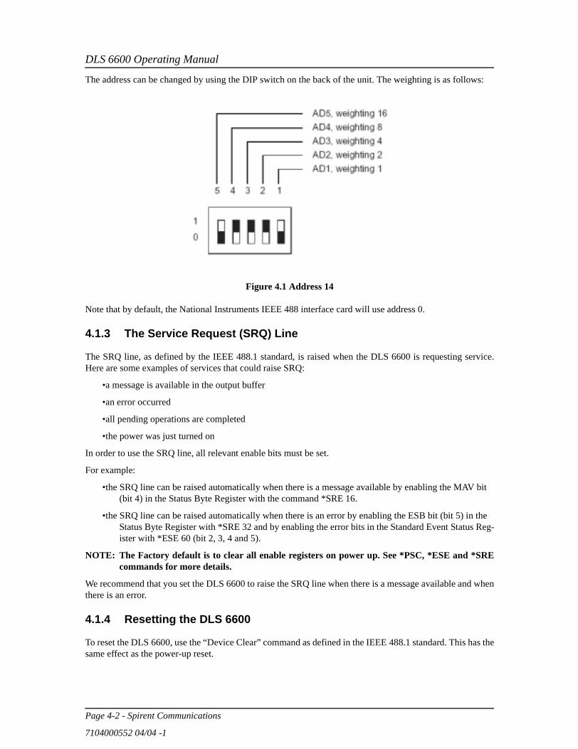
The address can be changed by using the DIP switch on the back of the unit. The weighting is as follows:
Figure 4.1 Address 14
Note that by default, the National Instruments IEEE 488 interface card will use address 0.
4.1.3 The Service Request (SRQ) Line
The SRQ line, as defined by the IEEE 488.1 standard, is raised when the DLS 6600 is requesting service.Here are some examples of services that could raise SRQ:
•a message is available in the output buffer
•an error occurred
•all pending operations are completed
•the power was just turned on
In order to use the SRQ line, all relevant enable bits must be set.
For example:
•the SRQ line can be raised automatically when there is a message available by enabling the MAV bit (bit 4) in the Status Byte Register with the command *SRE 16.
•the SRQ line can be raised automatically when there is an error by enabling the ESB bit (bit 5) in the Status Byte Register with *SRE 32 and by enabling the error bits in the Standard Event Status Reg-ister with *ESE 60 (bit 2, 3, 4 and 5).
NOTE: The Factory default is to clear all enable registers on power up. See *PSC, *ESE and *SREcommands for more details.
We recommend that you set the DLS 6600 to raise the SRQ line when there is a message available and whenthere is an error.
4.1.4 Resetting the DLS 6600
To reset the DLS 6600, use the “Device Clear” command as defined in the IEEE 488.1 standard. This has thesame effect as the power-up reset.
DLS 6600 Operating Manual
Spirent Communications - Page 4-3
7104000552 04/04 -1
4.1.5 Message Terminators
Messages to the DLS 6600 must be terminated with either a Line Feed character (ASCII <LF>, decimal 10,hex 0A), an IEEE 488.1 EOI signal, or both. Messages from the DLS 6600 are always terminated with aLine Feed character and the IEEE 488.1 EOI signal.
Note that some languages, such as BASIC, may automatically append a carriage return and a line feed at theend of messages. The carriage return character is not a valid terminator, and will invalidate the last com-mand. To avoid this problem, you can append a semi-colon after a string (after the quotes) when printing tothe IEEE 488 port. Another solution is to append a semi-colon at the end of the command itself (inside thequotes), so that the carriage return can be interpreted as a second command, and be simply discarded by theDLS 6600.
For example:
PRINT #1, “:SETTING:CHANNEL:STATE?”+CHR$(10); Preferred solutionor
PRINT #1, “:SETTING:CHANNEL:STATE?;” Other solution
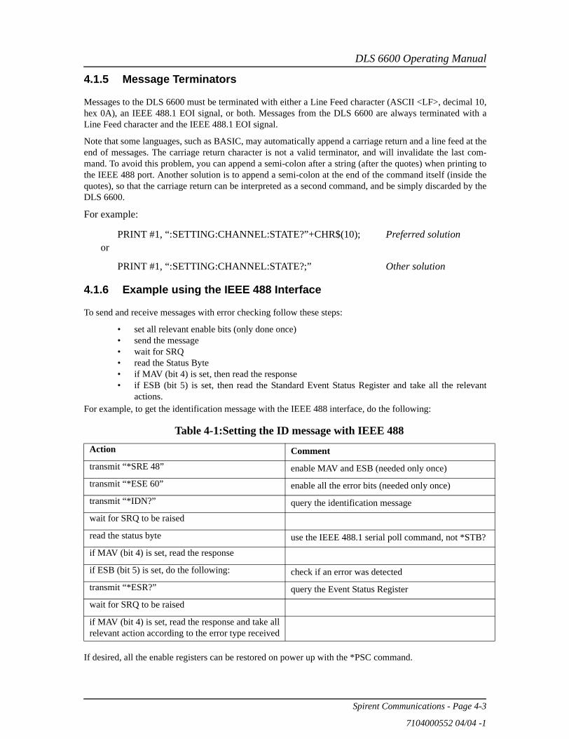
4.1.6 Example using the IEEE 488 Interface
To send and receive messages with error checking follow these steps:
• set all relevant enable bits (only done once)• send the message• wait for SRQ• read the Status Byte• if MAV (bit 4) is set, then read the response• if ESB (bit 5) is set, then read the Standard Event Status Register and take all the relevant
actions.For example, to get the identification message with the IEEE 488 interface, do the following:
If desired, all the enable registers can be restored on power up with the *PSC command.
Table 4-1:Setting the ID message with IEEE 488Action Commenttransmit “*SRE 48” enable MAV and ESB (needed only once)
transmit “*ESE 60” enable all the error bits (needed only once)
transmit “*IDN?” query the identification message
wait for SRQ to be raised
read the status byte use the IEEE 488.1 serial poll command, not *STB?
if MAV (bit 4) is set, read the response
if ESB (bit 5) is set, do the following: check if an error was detected
transmit “*ESR?” query the Event Status Register
wait for SRQ to be raised
if MAV (bit 4) is set, read the response and take allrelevant action according to the error type received
DLS 6600 Operating Manual
Page 4-4 - Spirent Communications
7104000552 04/04 -1
4.2 RS-232 Serial InterfaceThe DLS 6600 uses a female DB-25 connector, and is configured as a DCE device. It can therefore be con-nected directly to a PC serial port.
The RS-232 standard is equivalent to the European V.24/V.28 standards. In this manual we use the termRS-232 to refer to both of these two standards. Generally, the computer literature will use the words “serial”,“COM1” and “COM2” to refer to the RS-232 interface. Note that the DLS 6600 cannot use the parallel portof a computer (the female connector).
To use the RS-232 interface, simply connect your computer to the DLS 6600 and set the computer to 9600bps baud rate, no parity, 8 data bits per character, 1 stop bit and RTS/CTS hardware flow control.
Do NOT use a null modem with a computer that has a standard COM port configured as a DTE.
The DLS 6600 stops transmitting data when the RTS line is low, and restarts when the RTS line is high. TheDLS 6600 lowers the CTS and the DSR lines when it cannot accept data, and raises them when it can. Notethat the RTS line is not the usual “Request To Send” as defined by the RS-232 standard. If desired, the usercan leave the RTS line set, and use only the CTS line.
Most serial port communication programs can be used to control the DLS 6600. To use HyperTerminal,click on “Start” > “Programs” > “Accessories” > “HyperTerminal” > “hypertrm. exe”. When the programstart, enter a name, for example “DLS 6600”, select the port, for example “Direct to COM1”. Enter the portsettings: 9600, 8, none, 1 and hardware. Select “File” > “Properties” > “Settings” > “ASCII Setup”, enable“Send line ends with line feeds” and “Echo typed characters locally”, and finally press “OK” twice. Youshould now be able to send and receive commands to/from the MPS.
4.2.1 Message TerminatorsMessages sent to the DLS 6600 through the serial interface MUST be terminated with the line feed character(decimal 10, hex 0A, LF). To ensure that no characters are left in the receive buffer of the DLS 6600 from aprevious incomplete command, you can send the line feed character by itself before sending new commands.
Messages from the DLS 6600 are always terminated with a Line Feed character.
Note that some languages, such as BASIC, may automatically append a carriage return and a line feed at theend of messages. The carriage return character is not a valid terminator, and will invalidate the last com-mand. To avoid this problem, you can append a semi-colon after a string (after the quotes) when printing tothe communication port. Another solution is to append a semi-colon at the end of the command itself (insidethe quotes), so that the carriage return can be interpreted as a second command, and be simply discarded bythe DLS 6600. For example:
PRINT #1, “:set:channel:line 0”+CHR$(10); Preferred solutionorPRINT #1, “:set:channel:line 0;” Other solution
4.2.2 Example using the RS–232 Interface
To change the length of the line to 4000 ft, do the following:
1. transmit “:SET:CHAN:LINE 4000 ft”
1. check that the REMOTE LED is still green; if it turns red, see Section Chapter 5 "TROUBLESHOOTING", “Troubleshooting”.
To send and receive messages with error checking follow these steps:
DLS 6600 Operating Manual
Spirent Communications - Page 4-5
7104000552 04/04 -1
1. set all relevant enable bits (only done once)
1. send the message
1. read the answer until you receive LF (decimal 10, hex 0A)
1. check if an error occurred with the command *ESR?
For example, to get the identification message with the RS–232 interface, do the following:
1. transmit “*ESE 60”enable all the error bits (needed only once)
1. transmit “*IDN?” query the identification message
1. read the answer the messages are always terminated with LF
1. transmit “*ESR?” check if an error occurred
1. read the answer if not 0, see Section These bits are not used by the DLS 6600. fordescription of the error(s)
4.3 Data formats
The DLS 6600 adheres to the IEEE 488.2 principle of Forgiving Listening and Precise Talking.
The data formats supported by the DLS 6600 are:
Talking:a) <NR1> Numeric Response Data – Integerb) Arbitrary ASCII Response Data
<NR1> is an implicit point representation of an integer.
Arbitrary ASCII Response Data is a generic character string without any delimiting characters. It is usuallyused to send data in response to a query, such as with the *IDN? command (see Section Common CommandSet).
Listening: <NRf> Decimal Numeric Program Data
<NRf> is the Flexible Numeric Representation defined in the IEEE 488.2 standard which can represent justabout any number.
The DLS 6600 can accept data in the <NRf> format, which means that numbers can be made of a combina-tion of digits, signs, decimal point, exponent, multiplier, unit and spaces. For example, any of the followingis a valid representation for 4000 feet: 4kft, 4.0kft, 4000, .04e2k, 0.4 e4 ft, +4000. If a unit (i.e. ft, m, bps,etc.) is appended to a number, that unit must be valid and not abbreviated. Note that the period separates thedecimal part of a number.
4.4 Command Syntax
The DLS 6600 adheres to the IEEE 488.2 format for command syntax. As with the Data Format, theprinciple is Forgiving Listening and Precise Talking.
Commands may take one of two forms: either a Device Dependent Command starting with a colon (SectionThis shorter form is valid because both LINEs are at the same level.) or a Common Command starting witha star (Section Common Command Set). Each type may be preceded by one or more spaces, and each must
DLS 6600 Operating Manual
Page 4-6 - Spirent Communications
7104000552 04/04 -1
have one or more spaces between its mnemonic and the data associated with it.
Common commands are preceded by the character “*”. Device Dependent commands are preceded by acolon, with a colon separating each level of the command. Commands may be either in upper or lower case.Multiple commands may be concatenated by separating each command by semi-colons.
The following are some examples:
*RST
*RST;*WAI;:SET:CHANNEL:LINE 4000 ft
*ESE 45; *SRE 16
Messages to the DLS 6600 must be terminated with a Line Feed character (ASCII <LF>, decimal 10, hex0A). Messages from the 6600 are always terminated with a Line Feed character.
As defined in the SCPI specifications, a Device Dependent Command may be sent in its short form or longform, in upper or lower case. The following commands are therefore identical in operation:
:SET:CHANNEL:LINE 4000 ft
:SET:CHAN:LINE 4000 ft
Queries of the system follow the same format as the commands, except that the data normally associatedwith a command is replaced by a question mark “?”. Following receipt of such a command, the DLS 6600will place the appropriate response in the output queue, where the controller can read it. Examples are:
*IDN?
*ESE?;*SRE?
:SET:CHAN:LINE?
When a command does not begin with a colon, the DLS 6600 assumes that the command is at the same levelas the previous command. For example, to set a line one does NOT need to specify “:SYS:CAL” each time,as in:
:SYS:CAL:Date Dec 2001;Expiry Dec 2002
This shorter form is valid because both LINEs are at the same level.
4.5 Device Dependent Commands
As recommended by the SCPI consortium and to simplify programming of the various Access EmulationDivision simulators, the DLS 6600 uses the following tree structure:
:SETting:CHANnel
:LENgth <Length>:SYStem
KLock <ON|OFF>:COMMunicate
:SERial <PACE NONE | CTS | RTS/CTS | XON/XOFF | ALL>
Each section of the command may be sent in the full or the truncated form (indicated in upper case). Thecommand itself may be sent in upper or lower case form.
DLS 6600 Operating Manual
Spirent Communications - Page 4-7
7104000552 04/04 -1
The DLS 6600 will round any number to the nearest number permitted by the resolution of the parameter.
Sections Data formats and Command Syntax give more information on the data format and the commandsyntax.
4.5.1 :SETting:CHANnel:LENGTH <Length>
Select the length of the line, where the <Length> is the length of the simulated line.
The length of the DLS 6626 can be adjusted between 0 and 23.75 kft in 250 ft increments.
For example, to set the length of the line to 4000 ft, send:
:SET:CHAN:LENGTH 4000 ft
The units of the length are optional, but they must be in “ft” if present for the DLS 6626 or the DLS 6624 or"m" for the DLS 6604. For more details on the numeric format supported by the DLS 6600, see Section Dataformats.
To query the length currently simulated by the DLS 6600 send:
:SET:CHAN:LENGTH ?
The command will return the current length. For example, if the length of line is 4 kft, the returned messagewill be:
4000 FT
4.5.2 :SYStem:KLock ON/OFF
In the DLS 6600, the length of the simulated wireline channel can be set either by pushbuttons on the frontpanel or by remote control commands. At any time you can disable the front panel control via this definedcommand or by GPIB Local Lockout (LLO) message.
:System:Klock OFF
is the command to enable the front panel control again.
To query the current state send:
:System:Klock?
The command will return the current state. For example, if front panel control is
locked out (not available), the returned message will be:
ON
4.5.3 :SYStem:COMMunicate:SERrial:PACE <pace>
Set the receiver and transmitter pace method (flow control) of the serial interface, where <pace> is any ofthe following choices:
NONE | CTS | RTS/CTS | XON/XOFF | ALL
For example, to set the pace method to RTS/CTS, send:
:SYS:COMM:SER:PACE RTS/CTS
DLS 6600 Operating Manual
Page 4-8 - Spirent Communications
7104000552 04/04 -1
Note that the new pacing must be used immediately for any further serial communication.
To query the current pacing method send:
:SYS:COMM:SER:PACE?
The command will return the pacing method as a string. For example, if the pacing method is RTS/CTS, thereturned message will be:
RTS/CTS
To simplify the setting of the serial interface, we used a slightly modified SCPI command set. The SCPIstandard requires separate settings for the RTS/CTS flow control and XOn/XOff pacing, and differentiatesbetween the receive and the transmit sides. The command set of the XPS combines the ":RTS" and the"XON" settings into one ":PACE" command.
Note that the SCPI standard assumes a DTE configuration, whereas the XPS is configured as a DCE port(thus not requiring a Null Modem).
4.6 Common Command Set
As specified in the IEEE 488.2 standard, a number of common commands are required to set up and controlthe standard functions of remote-controlled devices. These common commands are as follows:
*CLS Clear Status CommandType: Status commandFunction: Clears the Event Status Register (ESR). Clearing the Event Status Register will also clear
ESB, the bit 5 of the Status Byte Register (STB). It has no effect on the output queue (bit 4of the STB).
*ESE <NRf> Event Status Enable
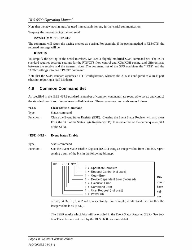
Type: Status commandFunction: Sets the Event Status Enable Register (ESER) using an integer value from 0 to 255, repre-
senting a sum of the bits in the following bit map:
Bits7 to 0haveval-ues
of 128, 64, 32, 16, 8, 4, 2 and 1, respectively. For example, if bits 3 and 5 are set then theinteger value is 40 (8+32).
The ESER masks which bits will be enabled in the Event Status Register (ESR). See Sec-tion These bits are not used by the DLS 6600. for more detail.
DLS 6600 Operating Manual
Spirent Communications - Page 4-9
7104000552 04/04 -1
On power-on, the register is cleared if the Power-on Status Clear bit is 1, or restored if thebit is 0 (see *PSC for more details).
*ESE? Event Status Enable QueryType: Status commandFunction: An integer value between 0 and 255 representing the value of the Event Status Enable
Register (ESER) is placed in the output queue. The possible values are described in the*ESE command section, and in more detail in Section Status Reporting.
*ESR? Event Status Register QueryType: Status commandFunction: An integer value between 0 and 255 representing the value of the Event Status Register
(ESR) is placed in the output queue. Once the value is placed in the output queue, the reg-ister is cleared. The command will turn the REMOTE LED green if the LED was red.The possible values are described in the *ESE command section, and in more detail inSection Status Reporting.
*IDN? Identification Query
Type: System commandFunction: Returns the ID of the unit. Upon receiving this command the DLS 6600 will put the fol-
lowing string into the output queue:
SPIRENT COMM. INC,DLS 6600,<SN>,<Ver>
where: <SN> is the serial number of the unit<Ver> is the revision level of the control firmware (always 2 digits)
*OPC Operation CompleteType: Synchronization commandFunction: Indicates to the controller when the current operation is complete. This command will
cause the DLS 6600 to set bit 0 in the Event Status Register (ESR) when all pending oper-ations are completed. The bit is read with the *ESR? command, which also clear the bit.Communication can proceed as normal after this command. See Section The setting of theEvent Status Register can be read with the Event Status Register query command(*ESR?). This will put the value of the register in the output queue, AND will clear theregister. for more details.
*OPC? Operation Complete QueryType: Synchronization commandFunction: Indicates when the current operation is complete. This will cause the DLS 6600 to put an
ASCII 1 (decimal 49, hex 31) in the output queue when the current operation is complete.Communication can proceed as normal after this command, but be prepared to receive the“1” at any time. See Section The setting of the Event Status Register can be read with the

DLS 6600 Operating Manual
Page 4-10 - Spirent Communications
7104000552 04/04 -1
Event Status Register query command (*ESR?). This will put the value of the register inthe output queue, AND will clear the register. for more details.
*PSC <NRf> Power-on Status ClearType: Status and event commandFunction: Indicates if the unit should clear the Service Request Enable Register and the Standard
Event Status Register at power-on. If 1 (or higher) then all the enable registers are clearedat power-on, if 0 then all the enable registers are restored from the non-volatile RAM atpower-on. The factory default is 1 (clear all the enable registers). Any change to the“Power-on Status” is saved in non-volatile RAM, and is always restored on power up.
*PSC? Power-on Status Clear QueryType: Status and event commandFunction: Return the Power-on Status Clear value. If 1 then all the enable registers are cleared at
power-on, if 0 then all the enable registers are restored from the non-volatile RAM atpower-on. The factory default is 1 (clear all the enable registers).
*RST ResetType: Internal commandFunction: IEEE 488.2 level 3 reset. This command will initialize the DLS 6600 with the bypass
loop, and cancel any pending *OPC operation. It will not affect the output buffer or othersystem settings of the unit. Note that this is NOT equivalent to the power-up reset.
*SRE <NRf> Service Request EnableType: Status commandFunction: Sets the Service Request Enable Register (SRER). An integer value indicates which ser-
vice is enabled, with the following bit map:
Bits 7 to 0 have values of 128, 64, 32, 16, 8, 4, 2 and 1, respectively. For example, if bits4 and 5 are set then the integer value is 48 (16+32).
On power-on, this register is cleared if the Power-on Status Clear bit is 1, or restored if thebit is 0 (see *PSC for more details).
*SRE? Service Request Enable Query
DLS 6600 Operating Manual
Spirent Communications - Page 4-11
7104000552 04/04 -1
Type: Status commandFunction: An integer value representing the value of the Service Request Enable Register is placed
in the output queue. The possible values are listed in the *SRE command section.
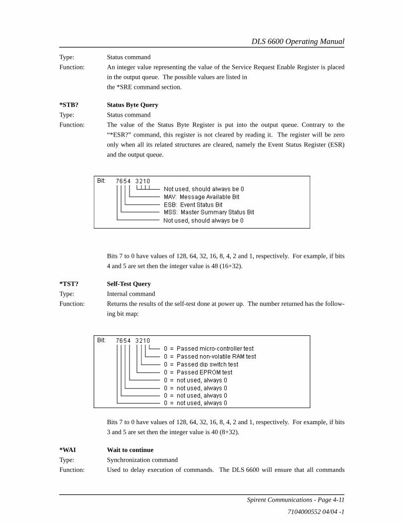
*STB? Status Byte QueryType: Status commandFunction: The value of the Status Byte Register is put into the output queue. Contrary to the
“*ESR?” command, this register is not cleared by reading it. The register will be zeroonly when all its related structures are cleared, namely the Event Status Register (ESR)and the output queue.
Bits 7 to 0 have values of 128, 64, 32, 16, 8, 4, 2 and 1, respectively. For example, if bits4 and 5 are set then the integer value is 48 (16+32).
*TST? Self-Test QueryType: Internal commandFunction: Returns the results of the self-test done at power up. The number returned has the follow-
ing bit map:
Bits 7 to 0 have values of 128, 64, 32, 16, 8, 4, 2 and 1, respectively. For example, if bits3 and 5 are set then the integer value is 40 (8+32).
*WAI Wait to continueType: Synchronization commandFunction: Used to delay execution of commands. The DLS 6600 will ensure that all commands

DLS 6600 Operating Manual
Page 4-12 - Spirent Communications
7104000552 04/04 -1
received before “*WAI” are completed before processing any new commands. Thismeans that all further communication with the 6600 will be frozen until all pending opera-tions are completed. See Section The setting of the Event Status Register can be read withthe Event Status Register query command (*ESR?). This will put the value of the registerin the output queue, AND will clear the register. for more details.
4.7 Status Reporting
There are two registers that record and report the system status, the Status Byte Register (STB), and theEvent Status Register (ESR).
For both registers there are three basic commands: one to read the register, one to set the enabling bits, andone to read the enabling bits (<NRf> is the new value of the register):
4.7.1 Status Byte Register (STB)
The bits of this register are mapped as follows:
bit 4: MAV (Message Available Bit)
Indicates that the Output Queue is not empty. If MAV goes high and is enabled then MSSgoes high.
bit 5: ESB (Event Status Bit)
It indicates that at least one bit of the Event Status Register is non zero and enabled. IfESB goes high and is enabled then MSS goes high.
bit 6: MSS/RQS (Master Summary Status/Request Service)
MSS is raised when either MAV or ESB are raised and enabled. RQS is defined by theIEEE 488.1 standard and are hardware related. MSS summarizes all the status bits of theDLS 6600, as defined by the IEEE 488.2 standard.
bits 7, 3, 2, 1, and 0
These bits are not used by the DLS 6600.
4.7.2 Event Status Register (ESR)
The Event Status Register monitors events within the system and reports on those enabled. It records
Status Byte Register Event Status Register
Read Register *STB? *ESR?
Set Enabling Bits *SRE <NRf> *ESE <NRf>
Read Enabling Bits *SRE? *ESE?
DLS 6600 Operating Manual
Spirent Communications - Page 4-13
7104000552 04/04 -1
transitory events as well. The DLS 6600 implements only the IEEE 488.2 Standard Event Status Register(ESR). It is defined as:
bit 0 Operation Complete. This bit is set in response to the *OPC command when the current operationis complete.
bit 1 Request Control. The DLS 6600 does not have the ability to control the IEEE 488 bus, and so thisbit is always 0.
bit 2 Query Error. There was an attempt to read an empty output queue or there was an output queueoverflow (maximum output queue capacity is 75 bytes).
bit 3 Device Dependent Error. This error bit is set when the DLS 6600 receives a command to set thelength of a fixed loop. Only variable loops can have their length changed.
bit 4 Execution Error. The data associated with a command was out of range.
bit 5 Command Error. Either a syntax error (order of command words) or a semantic error (spelling ofcommand words) has occurred. A GET (Group Execute Trigger) or *TRG command will also setthis bit.
bit 6 User Request. Indicates that the user has activated a Device Defined control through the frontpanel. Not used, so this bit is always 0.
bit 7 Power on. This bit is set when the DLS 6600 is turn on. Sending *ESR? clears the bit and it staysclear until the power is turned on again.
The setting of the Event Status Register can be read with the Event Status Register query command(*ESR?). This will put the value of the register in the output queue, AND will clear the register.
4.7.3 DLS 6600 Synchronization
The program controlling the DLS 6600 can use three different commands to synchronize with the

DLS 6600 Operating Manual
Page 4-14 - Spirent Communications
7104000552 04/04 -1
DLS 6600: *OPC, *OPC? and *WAI. The main differences are as follows:
1. if “Operation Complete” and ESB are enabled.1. if MAV is enabled.
The main difference between OPC and WAI is that WAI will block any further communication with theDLS 6600 until all pending operations are completed.
The main difference between *OPC and *OPC? is that *OPC sets the “Operation Complete” bit, and *OPC?will return an ASCII “1” when all pending operations are completed.
Make sure that all the required enable bits are set.
When using *OPC or *OPC?, the program controlling the DLS 6600 can determine when the operation iscompleted by waiting for SRQ, or by reading the status byte with the serial poll or with *STB? (if corre-sponding bits are enabled).
If the program uses the *OPC? command and then sends more queries, the program must be ready to receivethe “1” concatenated to other responses at any time. When using *WAI, the communication time out shouldbe set long enough to avoid losing data (the DLS 6600 needs approximately 2 seconds to set a loop).
Set Operation Complete bit when done
Return “1” when opera-
tion complete
Raise SRQ when opera-
tion complete
Block comm. with the
DLS 5102
Required Enable Bit(s)
*OPC Yes No Yes1 No Operation Complete,
ESB
*OPC? No Yes Yes2 No MAV
*WAI No No No Yes none

DLS 6600 Operating Manual
Spirent Communications - Page 5-1
7104000552 04/04 -1
5. TROUBLE SHOOTING
1. The power LED flashes red:
At power up, the DLS 6600 performs a self-test. If this self-test fails, the power LED flashes red. If this happens, consult the factory.
2. The power LED is orange:
If the DLS 6600 detects an internal error, it does a full system initialisation and turns the power LED orange. If this happens, consult the factory.
3. The remote LED is off:
This is normal after both a power-up and a reset.
4. The remote LED is red:
The DLS 6600 received an invalid command from the computer. See Chapter 4 "REMOTE CON-TROL" for more details.
5. The DLS 6600 program gives a communication error:
If using the serial interface:
• Check that no device (such as a mouse) is connected to the same serial port as the DLS 6600.• Check the cabling.

DLS 6600 Operating Manual
Page 5-2 - Spirent Communications
7104000552 04/04 -1

DLS 6600 Operating Manual
Spirent Communications - Page 6-1
7104000552 04/04 -1
6. REFERENCES
• IEEE 488.1-1987, IEEE Standard Digital Interface for Programmable Instrumentation (The Institute of Electrical and Electronics Engineers, Inc. 345 East 47th Street, New York, NY 10017-2394, USA)
• IEEE 488.2-1992, IEEE Standard Codes, Formats, Protocols, and Common Commands (The Institute of Electrical and Electronics Engineers, Inc. 345 East 47th Street, New York, NY 10017-2394, USA)
• SCPI Standard Commands for Programmable Instruments, available from some interface controller manufacturers (SCPI Consortium, 8380 Hercules Drive, Suite P.S., La Mesa, CA 91942, Phone: (619) 697-8790, Fax: (619) 697-5955)
• ITU-T Contributions during ITU-T SG15 Q4 rapporteur meeting in Durango, Colorado, USA (Interna-tional Telecommunication Union, Place des Nations, CH1211 Geneva 20, Switzerland)
• DC-048R2 Contributions to ITU-T SG15 Q4 (Spirent Communications, 750 Palladium Drive, Ottawa, Ontario, Canada K2V 1C7)
• ITU-T Recommendation G.996.1 (International Telecommunication Union, Place des Nations, CH1211 Geneva 20, Switzerland)
• ITU-T Recommendation G.992.3 (International Telecommunication Union, Place des Nations, CH1211 Geneva 20, Switzerland)
• ITU-T Draft Recommendation G.992.5, ADSL2plus specification (International Telecommunication Union, Place des Nations, CH1211 Geneva 20, Switzerland)
• ANSI T1.417, Spectrum Management for Loop Transmissions System (American National Standards Institute, 11 West 42nd Street, New York, NY 10036, USA)

DLS 6600 Operating Manual
Page 6-2 - Spirent Communications
7104000552 04/04 -1

DLS 6600 Operating Manual
Spirent Communications - Page 7-1
7104000552 04/04 -1
7. CUSTOMER SUPPORT
7.1 Customer Service Contact Information
For all North American customers, please direct any questions or concerns regarding the operation of a pur-chased unit, to the Spirent Communications Customer Service team by one of the following methods:
Direct Line: 613-592-7301
Toll free at: 800-465-1796
Fax at: 613-592-0522
E-mail at: [email protected].
All other customers should check the ae.spirentcom.com web site for the contact information of the nearestCustomer Service center or contact the main Spirent Communications service center for assistance (contactinformation is listed above).
For product information and updates, please visit the Spirent Communications web site at:
https://ae.spirentcom.com
For product manuals, software updates and more information, please visit the customer extranet at:
http://ae.spirentcom.com/secure/
Passwords for the extranet can be requested at:
http://ae.spirentcom.com/Customer_care/needlogin.htm.
7.2 Protecting Your Investment
Spirent Communications is committed to providing the highest quality products and customer support possi-ble. An annual calibration is required to ensure that your unit is operating properly.
Spirent Communications is pleased to offer two cost effective optional service programs. Each of these pro-grams is designed to improve the ease and efficiency of servicing Spirent Communications test equipment.

DLS 6600 Operating Manual
Page 7-2 - Spirent Communications
7104000552 04/04 -1

DLS 6600 Operating Manual
Spirent Communications - Page 8-1
7104000552 04/04 -1
8. WARRANTY
Spirent Communications warrants all equipment bearing its nameplate to be free from defects in workman-ship and materials, during normal use and service, for a period of twelve (12) months from the date of ship-ment.
In the event that a defect in any such equipment arises within the warranty period, it shall be the responsibil-ity of the customer to return the equipment by prepaid transportation to a Spirent Communications servicecentre prior to the expiration of the warranty period for the purpose of allowing Spirent Communications toinspect and repair the equipment.
If inspection by Spirent Communications discloses a defect in workmanship or material it shall, at its option,repair or replace the equipment without cost to the customer and return it to the customer by the least expen-sive mode of transportation, the cost of which shall be prepaid by Spirent Communications.
In no event shall this warranty apply to equipment which has been modified without the written authoriza-tion of Spirent Communications, or which has been subjected to abuse, neglect, accident or improper appli-cation. If inspection by Spirent Communications discloses that the repairs required are not covered underthis warranty, the regular repair charges shall apply to any repairs made to the equipment.
For international customers, please contact your local Spirent Communications sales representative or checkthe ae.spirentcom.com web site for the contact information of the nearest service center.
In North America, if warranty service becomes necessary, the customer must contact Spirent Communica-tions to obtain a return authorization number and shipping instructions:
Spirent Communications750 Palladium Drive
Ottawa, Ontario, CanadaK2V 1C7
Customer Service Direct Line: 613-592-7301Fax: 613-592-0522
Toll Free: [email protected]
This warranty constitutes the only warranty applicable to the equipment sold by Spirent Communications, and no other warranty or condition, statutory or otherwise, expressed or implied, shall be imposed upon Spirent Communications nor shall any representation made by any person, including a representation by a representative or agent of Spirent Communications, be effective to extend the warranty coverage provided herein.
In no event (including, but not limited to the negligence of Spirent Communications, its agents or employ-ees) shall Spirent Communications be liable for special consequential damages or damages arising from the loss of use of the equipment, and on the expiration of the warranty period all liability of Spirent Communi-cations whatsoever in connection with the equipment shall terminate.

DLS 6600 Operating Manual
Page 8-2 - Spirent Communications
7104000552 04/04 -1
DLS 6600 Operating Manual
Spirent Communications - Page 9-1
7104000552 04/04 -1
9. SHIPPING THE UNIT
To prepare the unit for shipment, turn the power off, disconnect all cables (including the power cable) andpack the simulators in their original cartons. Do not place any cables or accessories directly against the frontpanel as this may scratch the surface of the unit. It is highly recommended that all shipments are markedwith labels indicating that the contents are fragile.
If sending a unit back to the factory, ensure that the Return Material Authorization (RMA) number given bythe Spirent Communications Customer Service department is shown on the outside.
The RMA number is mandatory and must be obtained from a Spirent Communications Customer Servicecenter before shipping the unit (see Section 7 "CUSTOMER SUPPORT" for details on how to contact thenearest Spirent Communications Customer Service center).

DLS 6600 Operating Manual
Page 9-2 - Spirent Communications
7104000552 04/04 -1

DLS 6600 Operating Manual
Spirent Communications - Page 10-1
7104000552 04/04 -1
10. SPECIFICATIONS
10.1 GeneralType of Wire: DLS 6626: 26AWG (from ITU-T G.996.1)
Variable range: DLS 6626: 0 to 23.75 kft, in 250 ft increments
Bandwidth: DC to 4.5 MHz
DC Rating: 100 mA, 200 V maximum DC
Attenuation (Insertion Loss): MAE < 1 dB (20KHz - 4.5 MHz)
Impedance: + 10% (20 KHz - 4.5 MHz)
Control: Manual/Remote (remote via IEEE 488 or RS-232)
Connections: Manual: (one per side) 8-pin RJ-45 connectors, located on front panel
Remote front: 2 (one per side) 8-pin RJ-45 connectors
Remote back: 2 (one per side) two-pole terminal strips
CF Connectors
EnvironmentalOperating Temperature: 50ºF to 104ºF (+10ºC to +40ºC)Storage Temperature: -4ºF to 158ºF (-20ºC to +70ºC)Cable Reference Temperature: 72ºF (22ºC)Humidity: 90% non-condensing max.
Mechanical
Chassis Weight: 10 lbs/ 4.5 kg per chassisDimensions: 1.75” x 17” x 15” (44 mm x 423 mm x 384 mm)(H x W x D) 1U height
NOTE: Unit comes complete with rack mount brackets.
10.2 Included:1) DLS 6600 ADSL2++ Production Tester2) Manual3) AC to DC Wall Plug-in Adapter4) RS–232C Inter-connection Cable5) IEEE 488 (GPIB) Inter-connection Cable6) Control Software for use with Windows 98/NT/2000

DLS 6600 Operating Manual
Page 10-2 - Spirent Communications
7104000552 04/04 -1

DLS 6600 Operating Manual
Spirent Communications - Page 11-1
7104000552 04/04 -1
11. SAFETY
11.1 Information
11.1.1 Protective Grounding (Earthing)
This unit consists of an exposed metal chassis that is connected directly to ground (earth) via a power cord.The symbol used to indicate a protective grounding conductor terminal in the equipment is shown in thissection under “symbols”.
11.1.2 Before Operating the Unit
• Inspect the equipment for any signs of damage, and read this manual thoroughly.
• Become familiar with all safety symbols and instructions in this manual to ensure that the equipment is used and maintained safely.
11.1.3 Power Supply Requirements
AC Power: 100 - 130 VAC 60 Hz
or 230-240 VAC (±10%) 50/60 Hz
DC Power: DC used by the unit must be between 8.5 and 11 V. Note that the polarity of the DC Plugis: The inner conductor is positive (+) and the outer conductor is negative (-). See symbolsin the Safety section. The maximum current taken is 400 mA.
11.1.4 Fuse Configuration
There are no fuses used in the unit. A non-replaceable thermal fuse is used in the supplied AC/DC adapter.
11.1.5 Connections to a Power Supply
In accordance with international safety standards, the unit uses an approved AC/DC adapter.
AC Power: 100 - 130 VAC 60 Hz, North American 2 prong type.
or for use in CE Countries;
230-240 VAC (±10%) 50/60 Hz with 2 prong Europlug or 3 prong UK type, via AC to DCWall Plug-in Adapter.
DC Power: DC used by the unit must be between 8.5 and 11 V. Note that the polarity of the DC Plugis: The inner conductor is positive (+) and the outer conductor is negative (-). See symbolsin the Safety section. The maximum current taken is 400 mA.
11.1.6 Operating Environment
To prevent potential fire or shock hazard, do not expose the equipment to any source of excessive moisture.
DLS 6600 Operating Manual
Page 11-2 - Spirent Communications
7104000552 04/04 -1
11.1.7 Class of Equipment
The unit consists of an exposed metal chassis that is connected directly to earth via the protective groundingconductor. in accordance with the HARMONIZED EUROPEAN STANDARD EN 61010-1 1993, it is clas-sified as a Safety Class 1 equipment.
WARNING: This is a Class A product. In a domestic environment this product may cause radio interferencein which case the user may be required to take adequate measures.
11.2 Instructions
The following safety instructions must be observed whenever the unit is operated, serviced or repaired. Fail-ing to comply with any of these instructions or with any precaution or warning contained in the OperatingManual is in direct violation of the standards of design, manufacture and intended use of the equipment.
Spirent Communications assumes no liability for the customer’s failure to comply with any of these require-ments.
11.2.1 Before Operating the Unit• Inspect the equipment for any signs of damage, and read the Operating Manual thoroughly.
• Install the equipment as specified in the relevant section of this manual.
• Ensure that the equipment and any devices or cords connected to it are properly grounded.
11.2.2 Operating the Unit
• Do not operate the equipment when its covers or panels have been removed.
• Do not operate equipment if an interruption to the protective grounding is suspected. Ensure that the instrument remains inoperative.
• Unless absolutely necessary, do not attempt to adjust or perform any maintenance or repair procedure when the equipment is opened and connected to a power source at the same time. Any such procedure should only be performed by qualified service professional.
• Disconnect the power supply cord from the equipment before adding or removing any components.
• Operating the equipment in the presence of flammable gases or fumes is extremely hazardous.
• Do not perform any operating or maintenance procedure that is not described in the Operating and Ref-erence Manual.
• Some of the equipment’s capacitors may be charged even when the equipment is not connected the power source.

DLS 6600 Operating Manual
Spirent Communications - Page 11-3
7104000552 04/04 -1
11.3 SymbolsWhen any of these symbols appear on the unit, this is their meaning:
EQUIPOTENTIALITY–FUNCTIONALEARTH TERMINAL
PROTECTIVE GROUNDINGCONDUCTOR TERMINAL
CAUTION - REFER TO ACCOMPANYING DOCUMENTS

DLS 6600 Operating Manual
Page 11-4 - Spirent Communications
7104000552 04/04 -1

DLS 6600 Operating Manual
Spirent Communications - Page A-1
7104000552 04/04 -1
Appendix A MEASUREMENTS AND TEST RESULTS
A.1 Measurement of the DLS 6600
When measuring the insertion loss of a balanced line or line simulator throughout the frequency domain, the following method is recommended:
Figure A1.1 Electrical characteristics measurements
In Figure A1.1, Rg, RL and the coax cables match the unbalanced winding of the balun. The balanced wind-ing of the balun must be 100 Ω for 24AWG or 26AWG (North Hills 0301BB) or 135 Ohm for TP100 (NorthHills 0312BB), in order to match the reference impedance indicated in the standards. The centre tap on thebalanced side is usually connected to the shielding of the balun through one of the mounting screws.
The transmitter and receiver could be the transmitting and receiving sections of a network analyzer.
Transformers and cables introduce errors of attenuation and phase. For accurate measurements, first performcalibration (normalization) by replacing the simulator with a direct connection.
WARNING: The use of unbalanced signals through the DLS 6600 will usually give incorrect measure-ments.
A.2 Common Errors
There are three common errors:
• Coupling between input and output via the two transformers. When trying to measure attenuations of 60 dB or so, approximately 1/1000 of the input voltage, or 1/1000000 of the input power is present on the output. It is very easy for transformers - or even wires - placed close to each other to couple together far more than this. Take care to keep inputs and outputs separate.
• The use of a high impedance measuring device with no load from tip to ring at the receive end. This results in reflections due to a bad mismatch at the end of the line, and leads to very peculiar response curves.
• Ground injected directly onto the tip or ring of the wireline simulator. This almost always leads to a very noisy spectrum, with high background noise levels and often harmonically related spectrum “spikes”.

DLS 6600 Operating Manual
Page A-2 - Spirent Communications
7104000552 04/04 -1
A.3 Electrical Characteristics Test Results
Figure A3.1 DLS 6626 - Impedance 250 ft
Figure A3.2 DLS 6626 Impedance 1000 ft
Impedance - 250 ft
0
50
100
150
0.0 1.0 2.0 3.0 4.0 5.0
Frequency (MHz)
Impe
danc
e (O
hms)
TheoryMeasured
Impedance - 1000 ft
0
50
100
150
200
0.0 1.0 2.0 3.0 4.0 5.0
Frequency (MHz)
Impe
danc
e (O
hms)
TheoryMeasured

DLS 6600 Operating Manual
Spirent Communications - Page A-3
7104000552 04/04 -1
Figure A3.3 DLS 6626 Impedance 9000 ft
Figure A3.4 DLS 6626 - Attenuation 1000 ft
Impedance - 9000 ft
0.00
50.00
100.00
150.00
200.00
250.00
300.00
350.00
0.00 0.50 1.00 1.50 2.00 2.50 3.00 3.50
Frequency (MHz)
Impe
dnac
e (O
hms)
TheoryMeasured
Attenuation - 1000 ft
-20
-15
-10
-5
0
0 1 2 3 4 5Frequency (MHz)
Atte
nuat
ion
(dB
)
TheoreticalMeasured
MAE < 1dB
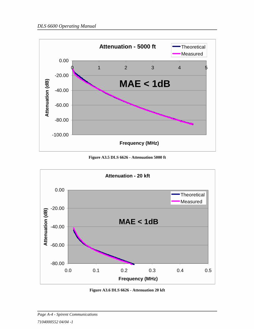
DLS 6600 Operating Manual
Page A-4 - Spirent Communications
7104000552 04/04 -1
Figure A3.5 DLS 6626 - Attenuation 5000 ft
Figure A3.6 DLS 6626 - Attenuation 20 kft
Attenuation - 5000 ft
-100.00
-80.00
-60.00
-40.00
-20.00
0.000 1 2 3 4 5
Frequency (MHz)
Atte
nuat
ion
(dB
)TheoreticalMeasured
MAE < 1dB
Attenuation - 20 kft
-80.00
-60.00
-40.00
-20.00
0.00
0.0 0.1 0.2 0.3 0.4 0.5
Frequency (MHz)
Atte
nuat
ion
(dB
)
TheoreticalMeasured
MAE < 1dB
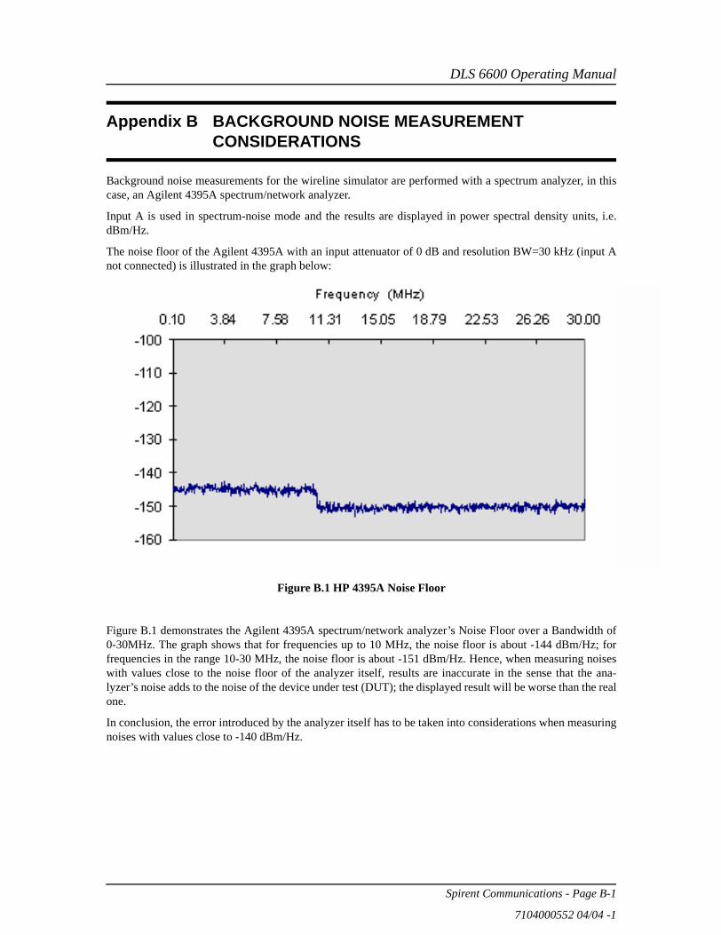
DLS 6600 Operating Manual
Spirent Communications - Page B-1
7104000552 04/04 -1
Appendix B BACKGROUND NOISE MEASUREMENT CONSIDERATIONS
Background noise measurements for the wireline simulator are performed with a spectrum analyzer, in thiscase, an Agilent 4395A spectrum/network analyzer.
Input A is used in spectrum-noise mode and the results are displayed in power spectral density units, i.e.dBm/Hz.
The noise floor of the Agilent 4395A with an input attenuator of 0 dB and resolution BW=30 kHz (input Anot connected) is illustrated in the graph below:
Figure 17 – HP 439
Figure B.1 HP 4395A Noise Floor
Figure B.1 demonstrates the Agilent 4395A spectrum/network analyzer’s Noise Floor over a Bandwidth of0-30MHz. The graph shows that for frequencies up to 10 MHz, the noise floor is about -144 dBm/Hz; forfrequencies in the range 10-30 MHz, the noise floor is about -151 dBm/Hz. Hence, when measuring noiseswith values close to the noise floor of the analyzer itself, results are inaccurate in the sense that the ana-lyzer’s noise adds to the noise of the device under test (DUT); the displayed result will be worse than the realone.
In conclusion, the error introduced by the analyzer itself has to be taken into considerations when measuringnoises with values close to -140 dBm/Hz.

DLS 6600 Operating Manual
Page B-2 - Spirent Communications
7104000552 04/04 -1