dm529 iv830 e1-pri isdn interface
TRANSCRIPT

Teldat Router E1/PRI ISDN Interface
Doc. DM529-I Rev. 8.30
May, 2000

- ii -
INDEX
Chapter 1 Introduction................................................................................................. 3 1. Introduction to E1/PRI ISDN interface .......................................................................... 4
Chapter 2 Configuration .............................................................................................. 5 1. E1/PRI ISDN Interface Configuration ........................................................................... 6
1.1. TYPE OF INTERFACE ..................................................................................... 6 a) Interface configured as E1 ................................................................................. 6 b) Interface configured as Primary ISDN................................................................ 6
1.2. CRC-4................................................................................................................ 6 1.3. MAXIMUM FRAME SIZE ................................................................................ 7 1.4. MODE ............................................................................................................... 7
2. E1/PRI ISDN Configuration Commands ....................................................................... 8 2.1. ? (HELP) ............................................................................................................ 9 2.2. DISABLE........................................................................................................... 9 2.3. ENABLE............................................................................................................ 9 2.4. LIST................................................................................................................... 10 2.5. SET.................................................................................................................... 10
a) SET CIRCUIT .................................................................................................... 10 • SET CIRCUIT MAX-FRAME-LENGTH..................................................... 11 • SET CIRCUIT TYPE................................................................................... 11
b) SET GLOBAL..................................................................................................... 12 • SET GLOBAL INTERFACE-TYPE............................................................. 12 • SET GLOBAL LOCAL-ADDRESS ............................................................. 12 • SET GLOBAL MAX-FRAME-LENGTH..................................................... 13 • SET GLOBAL MODE ................................................................................. 13
2.6. EXIT.................................................................................................................. 13 Chapter 3 Monitoring................................................................................................... 14
1. E1/PRI ISDN interface monitoring................................................................................ 15 1.1. ? (HELP) ............................................................................................................ 16 1.2. CALLS............................................................................................................... 16
a) CALLS ACTIVE.................................................................................................. 16 b) CALLS CLEARED.............................................................................................. 17
1.3. CAUSE .............................................................................................................. 17 1.4. CLEAR .............................................................................................................. 18
a) CLEAR CALLS................................................................................................... 18 b) CLEAR STATISTICS .......................................................................................... 18
1.5. STATE............................................................................................................... 18 1.6. STATISTICS ..................................................................................................... 19 1.7. EXIT.................................................................................................................. 19
2. E1/PRI ISDN interface statistics.................................................................................... 21

Chapter 1 Introduction

TELDAT ROUTER– Introduction to the E1/PRI ISDN Interface
I - 4
Doc.DM529-I Rev.8.30
1. Introduction to E1/PRI ISDN interface
This manual describes the function of the E1/PRI ISDN interface implemented in the Teldat Routers. For this you need to have a Centrix-F router with the G.703 interface card at 2048 Kbps (this supports the E1 and the Primary ISDN interfaces).
The E1 interface is a digital interface operating at a speed of 2048 Kbps with a frame length of 256 bits divided into 32 time-slots of 8 bits each with interlaced octets, each one being associated to one of the 32 structured channels (the 2048 kbps are divided among the 32 channels each being 64 Kbps) and thus carrying out multiplexion in the time. The 256 bits frame repetition frequency is 8000 Hz in order to obtain channel capacity of 64 Kbps. I.e. the subsequent frame repeats each 125 µs:
Bit 1 2 3 4 5 6 7 8 256
Chann Channel 0 Channel 1 … … Channel 30 Channel 31
The Primary ISDN interface (PRI ISDN) is the same as a 2048 Kbps digital interface with the same characteristics as the E1 interface but with the peculiarity of certain specifications appearing at the moment when the time slots are distributed. This question is dealt with below:
Channel 0 is used as the synchronization channel in both interfaces, carrying out both maintenance functions and operating quality monitoring.
However, in the case of the PRI ISDN interface, channel 16 is reserved for signaling when establishing calls (channel D) while in the E1 interface, channel 16 is simply another channel available to transmit any type of traffic. The standard specifies that should signaling be needed, this should go through channel 16 although if this is not required the channel can be used normally.
Channel 0 Channel 1 … Channel
16 Channel
17 … Channel
29 Channel
30 Channel
31
E1 SINC. g g g g g g g g PRI ISDN SINC. g g
Channel D g g g g g
Channels marked as “g” can be freely assigned for data transport at 64 Kbps each.
As you can see, the PRI ISDN interface is a personalized E1 interface where the channels are structured and characterized in a determined way.
The interface is implemented so it complies with the G.703, G.704 recommendations and I.431 for the physical layer, Q.921 for the link layer and Q.931 for the UIT-T access layer.

Chapter 2 Configuration

TELDAT ROUTER– E1/PRI ISDN Interface Configuration II - 6
Doc.DM529-I Rev.8.30
1. E1/PRI ISDN Interface Configuration
This chapter describes the parameters which can be configured in the E1/PRI ISDN interface. Depending on the behavior you require from the router, you will need to correctly configure the distinct options.
1.1. TYPE OF INTERFACE
The first thing to consider is the type of interface you are going to configure as it depends on this whether certain parameters are applicable or not.
a) Interface configured as E1 In the case of an E1 interface, all the channels (except 0) are available to the user as 64 Kbps B channels and can be used as required.
Regarding the type of connection that can be established for the E1 interface channels, only permanent connections are possible as all the circuits are configured as PVCs.
Given that all the circuits are permanent, it doesn’t make any sense to assign a number to the interface to receive calls (there are no calls) consequently, you cannot configure a ‘local address’.
b) Interface configured as Primary ISDN If, on the other hand, you wish to use the interface as Primary ISDN, channel 16 is not available as this is used for signaling (channel D). The rest of the available channels can be used as required (except 0).
In this case, you can configure the channels as permanent (PVC) or switched (SVC).
It is also possible to configure a number or a local address to which ISDN calls can be carried out.
The PVC channels are always assigned so other users cannot use them. The SVCs however are assigned at the moment the call is produced in order to establish the data link and therefore are shared among all the possible users (the channel through which the communication is going to be established is unknown at priori).
1.2. CRC-4
When it is necessary to provide additional protection for frame alignment simulation and/or when you wish to count on a better error monitoring capacity, you can use the CRC-4, cyclic redundancy check-4 method. This procedure is extensively described in the G.704 recommendation. Generally this process uses the channel 0 bits series (frame bits numbered from 1 to 8) in order to determine if this functionality is active and to carry out an encoding/decoding to check that the frame arrives aligned etc.
The router can be configured to operate whether the CRC-4 procedure is applied or not.
NOTE: When configuring the router, you must bear in mind the possibility of interoperation with other devices which do not permit CRC-4. This means you must enable or disable according to the devices operating together.

TELDAT ROUTER– E1/PRI ISDN Interface Configuration II - 7
Doc.DM529-I Rev.8.30
1.3. MAXIMUM FRAME SIZE
This permits you to establish a maximum frame size through the interface. The maximum size can be configured afterwards so that each channel cannot exceed the ‘general’ maximum size.
1.4. MODE
The mode option refers to the clock signals. In the terminal devices, the network supplier provides the clock signal received by the router. However on some occasions it may be necessary that one of the devices provides the clock signals. Under these circumstances you must advice the indicated router to provide these signals.

TELDAT ROUTER– E1/PRI ISDN Interface Configuration II - 8
Doc.DM529-I Rev.8.30
2. E1/PRI ISDN Configuration Commands
The E1/PRI ISDN configuration commands are described in this section. Through these commands you can configure the router behavior over this interface in order to achieve the functional specifications required.
The commands available here can be seen in the below table:
Command Function
? (HELP) Permits you to view the available commands or their options. DISABLE Disables the CRC-4. ENABLE Enables the CRC-4. LIST Displays the interface configuration information. SET Permits you to configure the value for various interface parameters according
to the required option. EXIT Returns to the configuration Config> prompt.
The letters written in bold, are the minimum number of characters required to activate the command.
Accessing the E1/PRI ISDN Configuration environment The configuration commands must be entered at the E1/PRI ISDN interface configuration prompt (E1/PRI config>). In order to access this prompt:
1. At the configuration prompt (Config>), the list of interfaces and associated interface number is displayed through the LIST DEVICES command.
2. Enter the command NETWORK followed by the interface number associated to the E1/PRI ISDN interface.
Example:
Config>LIST DEVICES Con Ifc Type of interface CSR CSR2 int --- 2 PPP Generic Dial 0 0 --- 3 PPP Generic Dial 0 0 --- 4 Router->Node 0 0 --- 5 Node->Router 0 0 ISDN 1 1 G.703 port (E1) F001600 F000C00 9E LAN 0 Ethernet A000000 1D WAN1 6 X25 F001620 F000D00 9D Config>NETWORK 1 -- E1 / Primary ISDN Configuration -- E1/PRI config>
TELDAT ROUTER– E1/PRI ISDN Interface Configuration II - 9
Doc.DM529-I Rev.8.30
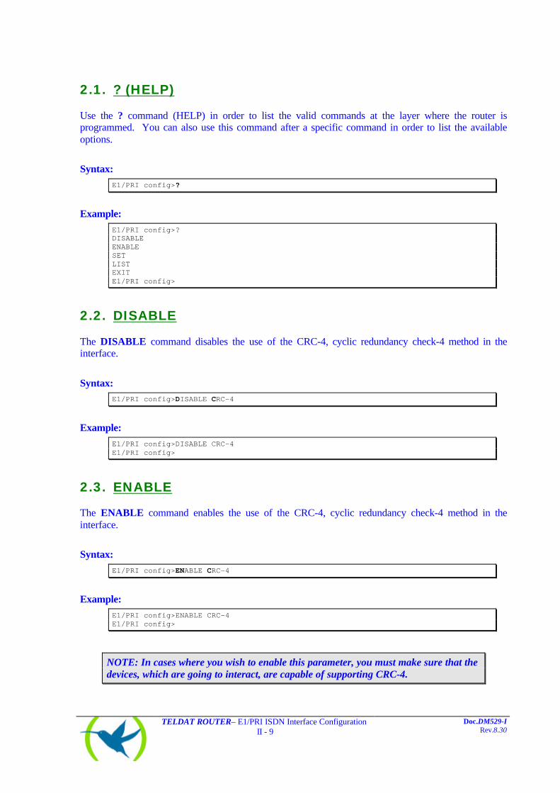
2.1. ? (HELP)
Use the ? command (HELP) in order to list the valid commands at the layer where the router is programmed. You can also use this command after a specific command in order to list the available options.
Syntax:
E1/PRI config>?
Example:
E1/PRI config>? DISABLE ENABLE SET LIST EXIT E1/PRI config>
2.2. DISABLE
The DISABLE command disables the use of the CRC-4, cyclic redundancy check-4 method in the interface.
Syntax: E1/PRI config>DISABLE CRC-4
Example:
E1/PRI config>DISABLE CRC-4 E1/PRI config>
2.3. ENABLE
The ENABLE command enables the use of the CRC-4, cyclic redundancy check-4 method in the interface.
Syntax:
E1/PRI config>ENABLE CRC-4
Example:
E1/PRI config>ENABLE CRC-4 E1/PRI config>
NOTE: In cases where you wish to enable this parameter, you must make sure that the devices, which are going to interact, are capable of supporting CRC-4.

TELDAT ROUTER– E1/PRI ISDN Interface Configuration II - 10
Doc.DM529-I Rev.8.30
2.4. LIST
The LIST command permits you to display the interface configuration, including the general parameters and those for each independent channel.
Syntax: E1/PRI config>LIST
Example:
E1/PRI config>LIST CRC-4 : Enabled Local address : Maximum frame length : 2048 Interface type : PRI ISDN Mode : EQUIPMENT B-01 B-02 B-03 B-04 B-05 B-06 B-07 B-08 B-09 B-10 ---------- ---- ---- ---- ---- ---- ---- ---- ---- ---- ---- MTU 2048 2048 2048 2048 2048 2048 2048 2048 2048 2048 Type svc svc svc svc svc svc svc svc svc svc B-11 B-12 B-13 B-14 B-15 B-17 B-18 B-19 B-20 B-21 ---------- ---- ---- ---- ---- ---- ---- ---- ---- ---- ---- MTU 2048 2048 2048 2048 2048 2048 2048 2048 2048 2048 Type svc svc svc svc svc svc svc svc svc svc B-22 B-23 B-24 B-25 B-26 B-27 B-28 B-29 B-30 B-31 ---------- ---- ---- ---- ---- ---- ---- ---- ---- ---- ---- MTU 2048 2048 2048 2048 2048 2048 2048 2048 2048 2048 Type svc svc svc svc svc svc svc svc svc svc E1/PRI config>
2.5. SET
The SET command permits you to configure various parameters both global (the whole interface) and parts of a determined circuit.
Syntax: E1/PRI config>SET <option, parameter, value>
NOTE: If you do not enter all the necessary parameters in the command line, the device will request these.
E1/PRI config>SET ? CIRCUIT GLOBAL
a) SET CIRCUIT Permits you to establish each circuit’s own parameters.
TELDAT ROUTER– E1/PRI ISDN Interface Configuration II - 11
Doc.DM529-I Rev.8.30
Syntax:
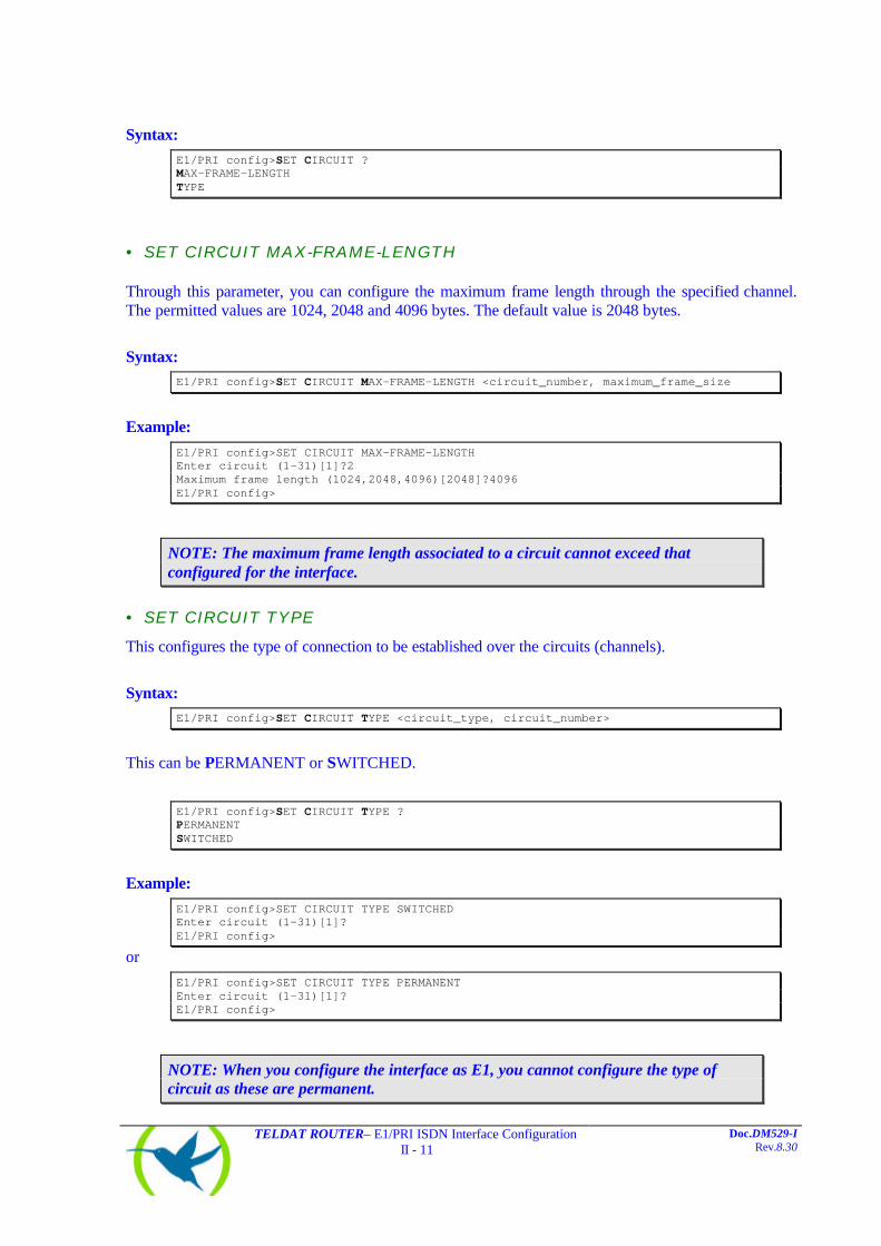
E1/PRI config>SET CIRCUIT ? MAX-FRAME-LENGTH TYPE
• SET CIRCUIT MAX-FRAME-LENGTH
Through this parameter, you can configure the maximum frame length through the specified channel. The permitted values are 1024, 2048 and 4096 bytes. The default value is 2048 bytes.
Syntax: E1/PRI config>SET CIRCUIT MAX-FRAME-LENGTH <circuit_number, maximum_frame_size
Example:
E1/PRI config>SET CIRCUIT MAX-FRAME-LENGTH Enter circuit (1-31)[1]?2 Maximum frame length (1024,2048,4096)[2048]?4096 E1/PRI config>
NOTE: The maximum frame length associated to a circuit cannot exceed that configured for the interface.
• SET CIRCUIT TYPE
This configures the type of connection to be established over the circuits (channels).
Syntax: E1/PRI config>SET CIRCUIT TYPE <circuit_type, circuit_number>
This can be PERMANENT or SWITCHED.
E1/PRI config>SET CIRCUIT TYPE ? PERMANENT SWITCHED
Example:
E1/PRI config>SET CIRCUIT TYPE SWITCHED Enter circuit (1-31)[1]? E1/PRI config>
or
E1/PRI config>SET CIRCUIT TYPE PERMANENT Enter circuit (1-31)[1]? E1/PRI config>
NOTE: When you configure the interface as E1, you cannot configure the type of circuit as these are permanent.
TELDAT ROUTER– E1/PRI ISDN Interface Configuration II - 12
Doc.DM529-I Rev.8.30
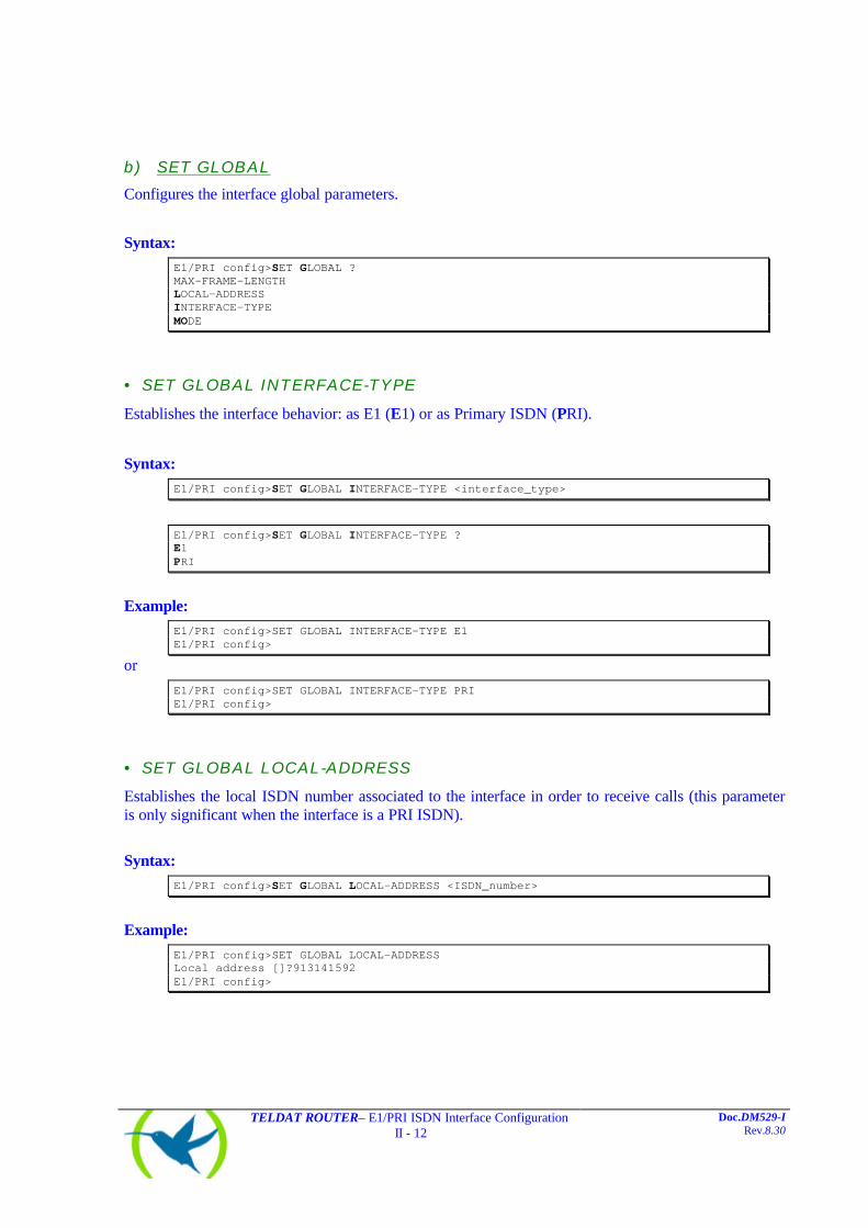
b) SET GLOBAL Configures the interface global parameters.
Syntax:
E1/PRI config>SET GLOBAL ? MAX-FRAME-LENGTH LOCAL-ADDRESS INTERFACE-TYPE MODE
• SET GLOBAL INTERFACE-TYPE
Establishes the interface behavior: as E1 (E1) or as Primary ISDN (PRI).
Syntax:
E1/PRI config>SET GLOBAL INTERFACE-TYPE <interface_type>
E1/PRI config>SET GLOBAL INTERFACE-TYPE ? E1 PRI
Example:
E1/PRI config>SET GLOBAL INTERFACE-TYPE E1 E1/PRI config>
or
E1/PRI config>SET GLOBAL INTERFACE-TYPE PRI E1/PRI config>
• SET GLOBAL LOCAL-ADDRESS
Establishes the local ISDN number associated to the interface in order to receive calls (this parameter is only significant when the interface is a PRI ISDN).
Syntax:
E1/PRI config>SET GLOBAL LOCAL-ADDRESS <ISDN_number>
Example:
E1/PRI config>SET GLOBAL LOCAL-ADDRESS Local address []?913141592 E1/PRI config>

TELDAT ROUTER– E1/PRI ISDN Interface Configuration II - 13
Doc.DM529-I Rev.8.30
• SET GLOBAL MAX-FRAME-LENGTH
The maximum frame length through the interface is configured through this parameter. The permitted values are 1024, 2048 and 4096 bytes. The default value is 2048 bytes.
Syntax: E1/PRI config>SET GLOBAL MAX-FRAME-LENGTH <maximum_frame_size>
Example:
E1/PRI config>SET GLOBAL MAX-FRAME-LENGTH Maximum frame length (1024,2048,4096)[2048]? E1/PRI config>
• SET GLOBAL MODE
This configures the device functionality as EQUIPMENT (the router will receive external clock signals and act as a ‘terminal’) or LINE (the router supplies the line clocks and acts as the ‘network’).
Syntax:
E1/PRI config>SET GLOBAL MODE <mode>
E1/PRI config>SET GLOBAL MODE ? EQUIPMENT LINE
Example:
E1/PRI config>SET GLOBAL MODE EQUIPMENT E1/PRI config>
or
E1/PRI config>SET GLOBAL MODE LINE E1/PRI config>
2.6. EXIT
Through this command, you exit the E1/PRI ISDN interface configuration menu and return to the configuration Config> prompt.
Syntax:
E1/PRI config>EXIT
Example:
E1/PRI config>EXIT Config>

Chapter 3 Monitoring

TELDAT ROUTER–E1/PRI ISDN Interface Monitoring III - 15
Doc.DM529-I Rev.8.30
1. E1/PRI ISDN interface monitoring
This section summarizes and explains all the E1/PRI ISDN interface monitoring commands. These commands permit you to monitor the interface behavior.
The available monitoring commands are seen in the below table:
Command Function
? (HELP) Permits you to list the available commands and their options. CALLS Displays the calls produced. CAUSE Returns the meanings of the call release codes. CLEAR Permits you to initialize the channel statistics and clear the released calls
buffer. STATE Displays the state and statistics of a B channel physical level. STATISTICS Displays the statistics of an active B channel. EXIT Returns to the global monitoring prompt (+).
The letters written in bold, are the minimum number of characters required to activate the command.
Accessing the E1/PRI ISDN Monitoring environment The E1/PRI ISDN interface monitoring commands must be entered at the E1/PRI> monitoring prompt. In order to access this prompt you need to carry out the following steps:
1. At the monitoring prompt (+), the list of interfaces and associated interface number is displayed through the DEVICES command.
2. Enter the command NETWORK followed by the interface number associated to the E1/PRI ISDN interface.
Example:
+DEVICE Auto-test Auto-test Maintenance Ifc Interface CSR Vect valids failures failures 0 Eth/0 A000000 1d 1 0 0 1 PRI/0 F001600 9e 1 1 0 2 PPP/0 0 0 1 2 0 3 PPP/1 0 0 1 2 0 4 R->N/0 0 0 1 0 0 +NETWORK 1 -- E1 / Primary ISDN Console -- E1/PRI>

TELDAT ROUTER–E1/PRI ISDN Interface Monitoring III - 16
Doc.DM529-I Rev.8.30
1.1. ? (HELP)
Use the ? command (HELP) in order to list the valid commands at the layer where the interface is being monitored. You can also use this command after a specific command in order to list the available options.
Syntax:
E1/PRI>?
Example:
E1/PRI>? CLEAR CAUSE STATISTICS STATE CALLS EXIT E1/PRI>
1.2. CALLS
Information on the calls is displayed through the CALLS command:
ACTIVE: displays data on the active calls CLEARED: displays information on the released calls.
Syntax: E1/PRI>CALLS <call_type>
E1/PRI>CALLS ? ACTIVE CLEARED
a) CALLS ACTIVE Example:
E1/PRI>CALLS ACTIVE TYPE CALLED NUMBER CALLING NUMBER REF CHAN T/START D/START CHARGE OUT 384200 001 1-B1 17:11:47 01/20/00 000000 E1/PRI>
The meaning of the various fields is as follows:
TYPE Incoming (IN) or outgoing (OUT).
CALLED NUMBER Telephone number called.
CALLING NUMBER Number of telephone calling.
REF Value of call reference in use.

TELDAT ROUTER–E1/PRI ISDN Interface Monitoring III - 17
Doc.DM529-I Rev.8.30
CHAN This is the line and channel through which the call has been established.
T/START Indicates the time the call was established.
D/START Indicates the day the call was established.
CHARGE Cost of the call (if the network provides this).
b) CALLS CLEARED Example:
E1/PRI>CALLS CLEARED L T CALLED N. CALLING N. CC DC T/START T/END D/START D/END CHARGE 1 O 384200 016 000 16:48:05 17:10:57 01/20/00 01/20/00 000000 E1/PRI>
The meaning of the various fields is as follows:
L T Line identifier and channel type.
CALLED N. Telephone number called.
CALLING N. Number of telephone calling.
CC Call release code (cause).
DC Diagnostic code.
T/START Time the call was established.
T/END Time the call was released.
D/START Day the call was established.
D/END Day the call was released.
CHARGE Cost of the call (if the network provides this).
NOTE: In cases of Permanent links, calls are not generated as the links are permanently established.
1.3. CAUSE
The CAUSE command returns the meaning of a specific release code. This command is for informative purposes in order to make it easier to understand the presented data.
Syntax:
E1/PRI>CAUSE <cause_code>

TELDAT ROUTER–E1/PRI ISDN Interface Monitoring III - 18
Doc.DM529-I Rev.8.30
Example:
E1/PRI>CAUSE 3 Cause (3): No route to the destination E1/PRI>
1.4. CLEAR
CLEAR enables you to delete the statistics of a specific channel or all of them such as the released calls buffer.
Syntax:
E1/PRI>CLEAR <option>
E1/PRI>CLEAR ? STATISTICS CALLS
a) CLEAR CALLS Clears the released calls buffer. Example:
E1/PRI>CLEAR CALLS E1/PRI>
b) CLEAR STATISTICS Deletes the B channel statistics. If you specify a channel number it will only delete the statistics relevant to that channel while if you do not indicate a number all the statistics for all the channels are deleted. Syntax:
E1/PRI>CLEAR STATISTICS <[channel]>
Example:
E1/PRI>CLEAR STATISTICS 5 E1/PRI>
1.5. STATE
The STATE command displays a B channel’s physical layer statistics and state.
TELDAT ROUTER–E1/PRI ISDN Interface Monitoring III - 19
Doc.DM529-I Rev.8.30
Syntax:
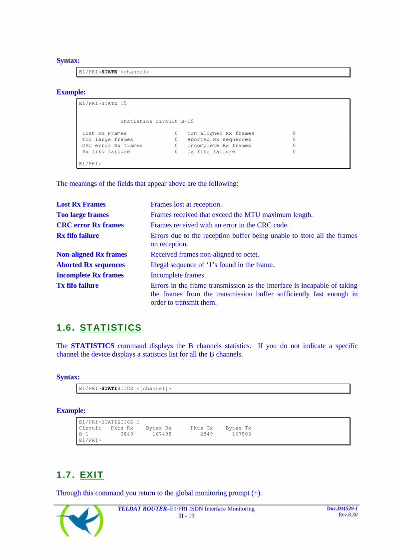
E1/PRI>STATE <channel>
Example:
E1/PRI>STATE 15 Statistics circuit B-15 Lost Rx Frames 0 Non aligned Rx frames 0 Too large frames 0 Aborted Rx sequences 0 CRC error Rx frames 0 Incomplete Rx frames 0 Rx fifo failure 0 Tx fifo failure 0 E1/PRI>
The meanings of the fields that appear above are the following:
Lost Rx Frames Frames lost at reception.
Too large frames Frames received that exceed the MTU maximum length.
CRC error Rx frames Frames received with an error in the CRC code.
Rx fifo failure Errors due to the reception buffer being unable to store all the frames on reception.
Non-aligned Rx frames Received frames non-aligned to octet.
Aborted Rx sequences Illegal sequence of ‘1’s found in the frame.
Incomplete Rx frames Incomplete frames.
Tx fifo failure Errors in the frame transmission as the interface is incapable of taking the frames from the transmission buffer sufficiently fast enough in order to transmit them.
1.6. STATISTICS
The STATISTICS command displays the B channels statistics. If you do not indicate a specific channel the device displays a statistics list for all the B channels.
Syntax:
E1/PRI>STATISTICS <[channel]>
Example:
E1/PRI>STATISTICS 1 Circuit Pkts Rx Bytes Rx Pkts Tx Bytes Tx B-1 2849 167498 2849 167503 E1/PRI>
1.7. EXIT
Through this command you return to the global monitoring prompt (+).
TELDAT ROUTER–E1/PRI ISDN Interface Monitoring III - 20
Doc.DM529-I Rev.8.30
Syntax: E1/PRI>EXIT
Example:
E1/PRI>EXIT +

TELDAT ROUTER–E1/PRI ISDN Interface Monitoring III - 21
Doc.DM529-I Rev.8.30
2. E1/PRI ISDN interface statistics
In order to view the interface statistics, enter the DEVICE command indicating the number of the interface whose statistics you wish to view at the monitoring prompt (+).
Example:
+DEVICE Auto-test Auto-test Maintenance Ifc Interface CSR Vect valids failures failures 0 Eth/0 A000000 1d 1 0 0 1 PRI/0 F001600 9e 0 0 0 2 PPP/0 0 0 1 2 0 3 PPP/1 0 0 1 2 0 4 R->N/0 0 0 1 0 0 +DEVICE 1 Auto-test Auto-test Maintenance Ifc Interface CSR Vect valids failures failures 1 PRI/0 F001600 9e 0 0 0 -- DS2153Q -- Rx Status: OK RIR:89 SSR:00 SR1:50 SR2:FB VCR: 0 FAS: 0 Layer 1 status: F1 +
The meaning of the fields is as follows:
Ifc Interface number.
Interface Type of interface and index.
CSR control/status/data register address.
Vect Interruption vector associated to the interface.
Auto-test valids Number of successful Auto-tests.
Auto-test failures Number of failed Auto-tests.
Maintenance failures Number of maintenance failures.
Rx Status Reception Status.
RIR, SSR, SR1, SR2, VCR, FAS Information on the status of the chip.
Layer 1 status Physical layer status.