dmr vs tetra comparison
TRANSCRIPT

Radio Activity S.r.l.
Headquarter: Via Ponte Nuovo, 8 - 20128 Milan – email: [email protected] - www.radioactivity-tlc.com
Tel. 02.36514205 - FAX/Voicebox 1782242408 – Registr. CCIAA Milano N° 1728248 - P.I./C.F. 04135130963
DMR versus TETRA
systems comparison
Version 1v2
ENB26 - DMR vs TETRA comparison 1v2.doc 07/09/2009 2 / 19
Index
ABSTRACT ..................................................................................................................................................... 3
CONSIDERATIONS ABOUT PROFESSIONAL MOBILE RADIO (PMR) SYSTEMS ........................ 4
The need of a professional mobile radio system ......................................................................................................... 4 Analog to digital PMR ................................................................................................................................................. 4 TETRA in brief ............................................................................................................................................................. 6 DMR in brief ............................................................................................................................................................... 7
DMR VERSUS TETRA COMPARISON ................................................................................................... 10
Radio frequency aspects ............................................................................................................................................10 Coverage ....................................................................................................................................................................... 10 Spectrum efficiency ...................................................................................................................................................... 12 Propagation delay tolerance ......................................................................................................................................... 13 “Cell enhancer” tunnel coverage .................................................................................................................................. 14 Green IT ........................................................................................................................................................................ 14
System aspects ..........................................................................................................................................................14 Features ........................................................................................................................................................................ 14 Flexibility and Simplicity ............................................................................................................................................... 15 Availability .................................................................................................................................................................... 15 Analog migration and coexistence ................................................................................................................................ 15 Open standard .............................................................................................................................................................. 16 Reliability ...................................................................................................................................................................... 16
Costs ..........................................................................................................................................................................17 Terminals ...................................................................................................................................................................... 17 Base station and node switches ................................................................................................................................... 17 New sites and frequency licenses ................................................................................................................................. 17 Migration cost ............................................................................................................................................................... 18
CONCLUSION .............................................................................................................................................. 19
ENB26 - DMR vs TETRA comparison 1v2.doc 07/09/2009 3 / 19
ABSTRACT
People perceive the word “digital” as more advanced and better than “analog” as it presents a number of attractive
advantages to the users. Normally this sentence is true, but which technology is the right choice?
This document gives an overview about the most popular digital technologies: TETRA, DMR, P25, dPMR and
TETRAPOL. The analysis focuses on the comparison between TETRA and the DMR as the major European digital
standards (and among of the most important in the world).
The purpose of this paper is not to provide an exhaustive and detailed technical comparison between these digital
standards but rather to provide the key points for deciding correctly which is more suited to your needs. Some
technical details may be debatable, and perhaps some could consider them in a different way (any suggestion or
correction is encouraged). However, the main concepts explained should give to the reader coherent arguments
about the technology that best suits its needs.
In this sense it is important to pay attention to the cost: the coverage area of a TETRA base station is approximately
between half and one third compared to that of an analog or DMR radio system, therefore TETRA needs a lot of more
sites. A medium size TETRA system may costs 3 to 5 times more than a DMR one. The features of these systems are
near the same (digital encryption, positioning, messaging ...) and the younger DMR is developing rapidly the
applications not yet available. Then there must be very good reasons to justify the TETRA huge cost increases
compared to the DMR.
The alleged spectral efficiency of TETRA has to be considered accurately. In fact TETRA lower RF budget could be cause
of the problematic frequency reuse, the poor adjacent channel selectivity and the control channel continuously on air.
DMR present a true no-compromises 6.25 KHz/CH solution.
The data transmission in TETRA is often sold as video applications ready. Who reasonably may use a full TETRA carrier
to send only one real time video on 22kb/s channel? Probably there are many other ways to perform better with more
bandwidth the desired video services with negligible cost (UMTS, GPRS, WiFI, WiMAX …).
An other aspect to consider is the migration process: from this point of view TETRA is a “revolution” instead the DMR
is an “evolution” of the existing analog two-way radio.
TETRA is a trunking system targeted to point to point communications in multi cell and high traffic density
environments. Like a telephone network, hundreds of users in a little area require a lot of radio cells to deliver the
communications. DMR is a dedicated channel or trunking system targeted to provide robust coverage rather than
capacity.
At the end, TETRA may give some advantages over DMR especially for medium to high capacity networks such as big
town or large campus. If this is not the case of the reader, it is advisable to request a DMR quoted solution before to
choose a digital radio system.

ENB26 - DMR vs TETRA comparison 1v2.doc 07/09/2009 4 / 19
CONSIDERATIONS ABOUT PROFESSIONAL MOBILE RADIO (PMR) SYSTEMS
The need of a professional mobile radio system
Normally the public cellular system (GSM) may not work in emergency because of saturation of the access channels of
the cells that leads to slow traffic until to make the communications impossible. A dedicated radio system should
ensure communication success even during overload situations.
During an emergency the people involved in it have to communicate in group mode (point to multipoint). This
facilitates the operations because everyone knows in real-time the current situation. It is important to perform a very
fast group call set-up within 0.5 seconds many times lower than the many seconds (typically 5 to 10s) that are
required for a GSM network.
At the end, the coverage area of the public cellular phone network is targeted to cover the maximum population; it is
not targeted to cover potentially risk area such as mountain, tunnels and remote locations.
Due the previous reasons the emergency Entities require an affordable, flexible, highly reliable, proprietary radio
communications network.
Analog to digital PMR
Different types of mobile communication technologies as analog or digital, conventional or Trunked, and so on have
been used in PMR market in the world. The marketplace perceives the word digital as more advanced and better than
analog as it presents a number of key advantages to the user, system operators and in the area of spectrum
management. Even though analogue FM PMR communications will remain a viable option for several years, digital
radio provides relative advantages in:
∞ improved voice quality at the fringes of reception;
∞ enhanced spectral efficiency (lower frequency license costs per channel);
∞ wireless data capability in the same equipment;
∞ powerful features like:
o individual, group and broadcast call;
o emergency call;
o digital communications security without degrading voice quality;
o terminal ID on PTT;
o late entry;
o call alert on individual call;
o polite/impolite channel access;
o IP based data capability;
o text messages;
o automatic position messages;
o remote radio monitor/ disable/ check;
∞ standard multi-vendors solutions;
∞ low cost TCP/IP based network backbone.
By contrast, the digital terminals, may suffer by some unpleasant proprieties:
∞ at the fringes of coverage area the communication may be on/off without a smooth degradation. In this
condition the “analog user” may continue to receive (with some difficulties) a very noisy communication. This
situation doesn’t involve base stations with diversity reception that dramatically improves the receiver
capability.
∞ the vocoded audio quality is not as good as an analog one. When the RF field is good, the analog songs as “HI-
FI” instead of “sufficient” of the digital one.
Nowadays a public safety communications tends to migrate from analog solutions to digital interoperable standards.
Many technologies are available for this purpose:

ENB26 - DMR vs TETRA comparison 1v2.doc 07/09/2009 5 / 19
∞ TErrestrial TRunked RAdio (TETRA)
∞ Digital Mobile Radio (PMR)
∞ Digital Private Mobile Radio (dPMR)
∞ Project 25 (P-25 or APCO-25)
∞ TETRAPOL
∞ …
The TETRA system, providing 4 channels for each 25KHz spaced carrier, is suitable for trunking systems that should
ensure a medium/high volume traffic. TETRA’s primary mode uses π/4 DQPSK modulation
that requires a linear or linearized amplifier. The connecting link between the stations require
a significant bandwidth to transfer all required signalling (typically in the order of 2Mb/s). The
network is of "cellular type" with different frequencies for each repeater and cells size
smaller compared with analogue ones. A number of European countries have adopted TETRA
for police interoperability.
The DMR standard (ETSI TS 102-361) allows to use a 12.5KHz spaced radio carrier to send two simultaneous radio
channels. The spectral efficiency of a single base station is the same as TETRA (1 CH/6.25KHz) but it may be better
because simulcast network configuration can be implemented. The modulation, unlike
the TETRA, is "constant envelope" type. This property allows to reach lower current
consumptions and better efficiency, not having to use linear RF amplifiers it simplifies
both terminals and network equipment. The coverage area of a radio station is the
same to the one with analogue modulation. These networks are suitable for
low/medium traffic networks or for mixed data/voice communications systems (e.g. audio + geographical
localization). Finally it should be noted that network and terminals are "dual mode" designed, that is they allow the
coexistence of traditional (analogue) and digital devices thus permitting a "soft migration" from analogue to digital
system.
TX CH1
TX CH2+
TX CH1+CH2
2 conventional channels
2 DMR channels
Group 1
Group 2
Group 2Group 1
freq 2
freq 1
TS 1 TS 2
Same
frequency
Fig. 1: analog to DMR soft migration.
The dPMR standard offers one communication per 6.25kHz channel bandwidth in Frequency Division Multiple Access
(FDMA) technology. This solution may be appropriate in very low traffic environments where 1 channel is enough for
the user need. When more than 1 channel is required, it is necessary to implement expensive branching systems with
halved RF power.
The compatibility with the adjacent 12.5KHz analog channels is not assured. Due to the modulation contents of the
dPMR, some noise may appears in the adjacent channels.
frequency
Analog dPMR Analog
12.5KHz12.5KHz
45-50dB
Fig. 2: possible noise between dPMR and adjacent analog channels.
ENB26 - DMR vs TETRA comparison 1v2.doc 07/09/2009 6 / 19
Due to these limitations, this system doesn’t appear interesting for the European market in which the channelization
has a 12.5KHz main raster and the frequency congestion requires true band optimization.
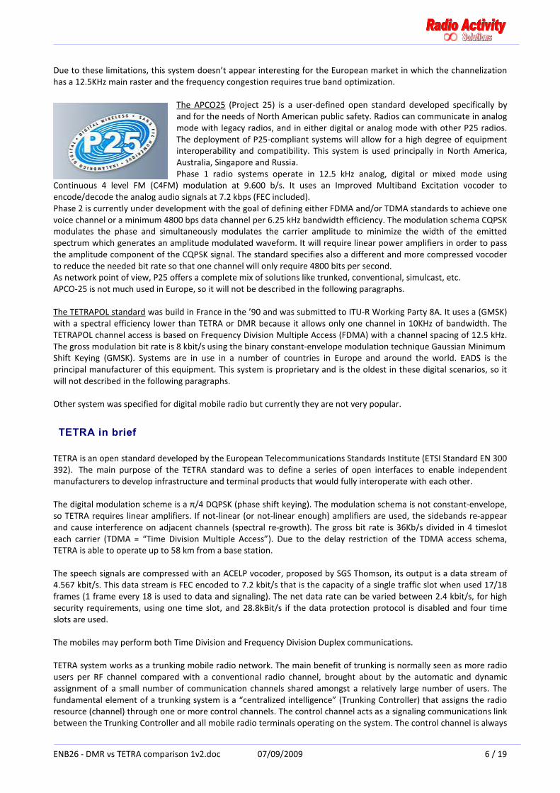
The APCO25 (Project 25) is a user-defined open standard developed specifically by
and for the needs of North American public safety. Radios can communicate in analog
mode with legacy radios, and in either digital or analog mode with other P25 radios.
The deployment of P25-compliant systems will allow for a high degree of equipment
interoperability and compatibility. This system is used principally in North America,
Australia, Singapore and Russia.
Phase 1 radio systems operate in 12.5 kHz analog, digital or mixed mode using
Continuous 4 level FM (C4FM) modulation at 9.600 b/s. It uses an Improved Multiband Excitation vocoder to
encode/decode the analog audio signals at 7.2 kbps (FEC included).
Phase 2 is currently under development with the goal of defining either FDMA and/or TDMA standards to achieve one
voice channel or a minimum 4800 bps data channel per 6.25 kHz bandwidth efficiency. The modulation schema CQPSK
modulates the phase and simultaneously modulates the carrier amplitude to minimize the width of the emitted
spectrum which generates an amplitude modulated waveform. It will require linear power amplifiers in order to pass
the amplitude component of the CQPSK signal. The standard specifies also a different and more compressed vocoder
to reduce the needed bit rate so that one channel will only require 4800 bits per second.
As network point of view, P25 offers a complete mix of solutions like trunked, conventional, simulcast, etc.
APCO-25 is not much used in Europe, so it will not be described in the following paragraphs.
The TETRAPOL standard was build in France in the ’90 and was submitted to ITU-R Working Party 8A. It uses a (GMSK)
with a spectral efficiency lower than TETRA or DMR because it allows only one channel in 10KHz of bandwidth. The
TETRAPOL channel access is based on Frequency Division Multiple Access (FDMA) with a channel spacing of 12.5 kHz.
The gross modulation bit rate is 8 kbit/s using the binary constant-envelope modulation technique Gaussian Minimum
Shift Keying (GMSK). Systems are in use in a number of countries in Europe and around the world. EADS is the
principal manufacturer of this equipment. This system is proprietary and is the oldest in these digital scenarios, so it
will not described in the following paragraphs.
Other system was specified for digital mobile radio but currently they are not very popular.
TETRA in brief
TETRA is an open standard developed by the European Telecommunications Standards Institute (ETSI Standard EN 300
392). The main purpose of the TETRA standard was to define a series of open interfaces to enable independent
manufacturers to develop infrastructure and terminal products that would fully interoperate with each other.
The digital modulation scheme is a π/4 DQPSK (phase shift keying). The modulation schema is not constant-envelope,
so TETRA requires linear amplifiers. If not-linear (or not-linear enough) amplifiers are used, the sidebands re-appear
and cause interference on adjacent channels (spectral re-growth). The gross bit rate is 36Kb/s divided in 4 timeslot
each carrier (TDMA = “Time Division Multiple Access”). Due to the delay restriction of the TDMA access schema,
TETRA is able to operate up to 58 km from a base station.
The speech signals are compressed with an ACELP vocoder, proposed by SGS Thomson, its output is a data stream of
4.567 kbit/s. This data stream is FEC encoded to 7.2 kbit/s that is the capacity of a single traffic slot when used 17/18
frames (1 frame every 18 is used to data and signaling). The net data rate can be varied between 2.4 kbit/s, for high
security requirements, using one time slot, and 28.8kBit/s if the data protection protocol is disabled and four time
slots are used.
The mobiles may perform both Time Division and Frequency Division Duplex communications.
TETRA system works as a trunking mobile radio network. The main benefit of trunking is normally seen as more radio
users per RF channel compared with a conventional radio channel, brought about by the automatic and dynamic
assignment of a small number of communication channels shared amongst a relatively large number of users. The
fundamental element of a trunking system is a “centralized intelligence” (Trunking Controller) that assigns the radio
resource (channel) through one or more control channels. The control channel acts as a signaling communications link
between the Trunking Controller and all mobile radio terminals operating on the system. The control channel is always
ENB26 - DMR vs TETRA comparison 1v2.doc 07/09/2009 7 / 19
on air in absence of traffic also. The base stations normally transmit continuously and all slots should be filled with an
idle burst.
The hand-over process, due to the trunking nature of TETRA, requires good RF field with large overlap areas to
perform efficiently. The backbone network of a TETRA system should allocate bandwidth enough to fast
transportation of digital audio and signaling and it should be equipped by fast switch nodes.
The TETRA standard will evolve to the Release 2 that will provide additional enhancements as:
• range extended up to 83 km
• more compressed codec
• many choices of modulation and RF bandwidth
• data transmission up to 500 kbits/s on 150KHz bandwidth
DMR in brief
DMR standard (ETSI TS 102 361 technical specification) is an open standard, defined in ETSI world by a working group
made of main PMR equipment producers of the world. The DMR standard building followed guide lines of PMR
market requirements for digital flexible systems, able to give added value to the present analogical systems, but at the
same time to guarantee a gradual migration between the two technologies, making investments and specific
operative existing requirements safe.
To this aim Radio Activity DMR repeaters are designed with the double standard technology, they are able to work
both in analogical and digital way, then supporting both classic PMR terminals and the new DMR ones, with every
operating characteristic of each technology (“dual mode”):
∞ voice communications with FM analogical modulation and selective calling based on traditional protocols;
∞ voice communications and data transmission with 4FSK digital modulation, according to the DMR standard,
with 9600 bps gross total speed.
Furthermore the selection of required working mode is fully automatic, this means that the repeater is able to
autonomously detect if the incoming communication is analogical or digital and can consequently configures itself to
work as a PMR or DMR respectively.
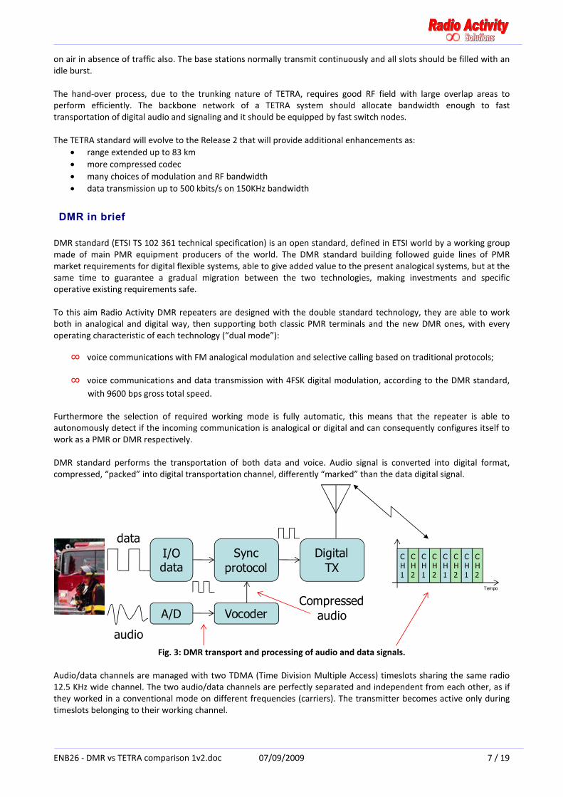
DMR standard performs the transportation of both data and voice. Audio signal is converted into digital format,
compressed, “packed” into digital transportation channel, differently “marked” than the data digital signal.
A/D
data
audio
Vocoder
Sync
protocol
Digital
TXC
H
1
C
H
2
C
H
1
C
H
2
C
H
1
C
H
2
C
H
1
C
H
2
Tempo
I/O data
Compressed
audio
Fig. 3: DMR transport and processing of audio and data signals.
Audio/data channels are managed with two TDMA (Time Division Multiple Access) timeslots sharing the same radio
12.5 KHz wide channel. The two audio/data channels are perfectly separated and independent from each other, as if
they worked in a conventional mode on different frequencies (carriers). The transmitter becomes active only during
timeslots belonging to their working channel.

ENB26 - DMR vs TETRA comparison 1v2.doc 07/09/2009 8 / 19
CH1
CH2
CH1
CH2
CH1
CH2
CH1
CH2
Group 1 Group 2
Time
CH2
Frequency
CH1
7.5KHz
CH4
CH3
7.5KHz
12.5KHz
Two contemporary
and indipendent communications on
the same frequency
carrier
30ms
Fig. 4: audio/data channels and TDMA timeslots.
DMR systems can live together with conventional analogical systems on adjacent channels without any performance
degradation for both. DMR system has a spectral efficiency of
1CH/6.25KHz, the same as TETRA and double in comparison with
conventional systems. Only one radio head (only one transmitter)
gives 2 CH without the need of RF coupling systems, with the effect of
lower costs and consumptions and greater available power.
Furthermore, DMR system allows the direct communications
between terminals. In this case only one channel per 12.5KHz will be
available because the synchronization is made by repeater/network.
Fig.5: Analog and DMR coexistence.
The implemented modulation is 4FSK type (Four-level Shift Keying),
optimal for use with PMR communications. Information bits are
transmitted by couples, each couple is assigned to a frequency shift.
The modulation is constant envelope frequency type. This implies
great advantages in terms of energy consumption: transmitters are
very similar to their classic analogical version, expensive
linearization is not required, and they can work in saturation mode
(C class or superior) with energy saving and consumption
compatible with solar panels systems. Fig. 6: DMR modulation type.
The modulator must have a flat frequency
response between 0 and 5 KHz.
Transmitted RF power level by a DMR systems is
the same as the one of a traditional analogical
system (constant envelop).
The sensitivity of a DMR receiver is about the
same as the one of a traditional analogical
system, but the audio quality remain constant up
to the sensitivity limit and the coverage is slightly
bigger than 12.5 KHz analogical systems.
Fig. 7: Frequency modulation constant envelope type.
DMR terminals can work in “open channel” mode like traditional systems for emergencies, but individual calls and
group calls are available: obviously selective callings are addressed in a digital format between DMR equipments.
Network access of DMR terminals is regulated by a “colour code” which replaces sub-tone sub-audio tone.
CH2
Frequenza
CH1
7.5KHz
CH3
7.5KHz
12.5KHz
Time
RF signal
Frequency
Central frequency
(not transmitted)
00 01
+1,944 kHz
+0,648 kHz
1011
-1,944 kHz
4FSK
7K60FXE

ENB26 - DMR vs TETRA comparison 1v2.doc 07/09/2009 9 / 19
RF field / distance
Quality
AnalogDMR
20dB SINAD
Area of greater
benefit of DMR
12dB SINAD
Fig. 8: evolution of quality in relation to the RF field/distance both for Analog and DMR.
The DMR performs the simulcast technology also. A simulcast network is a very powerful radio network in which all
the repeaters are active on the same frequency and at the same time.
Main advantages:
∞ Automatic and continuous roaming and
hand-over => Easy to use
∞ Functioning like single “big repeater” =>
automatic and simple conference call
operation
∞ All stations directly connected to the network
=> Integrated communication sys
∞ The same RF channel over all Network => no
change of channel in the coverage area, one
communication per channel
Every channel of the system is independent from the other channel. The communications in one channel can be
transfer to another channel by a junction at master/Central Office level or by adding a trunking controller in the
master station.
The area of coverage of every
single simulcast channel could be
expand easily by adding some
simulcast base stations. These
simulcast base stations will be
integrated in the network with few
operations at network level only
(nothing is request on mobile
terminals).
The simulcast network removes
the need of scan on mobiles and
portables, assures real time
roaming and hand over during the
call and reduces frequency license
costs.
���� Note that in the following paragraphs we will usually consider a TETRA system compared with a DMR simulcast
system to confront the systems with near the same features.
fcfc
S
MS
S
S
Backbone links
between base stations
Single site cell
coverage
Overlap area
Simulcast
“big cell”
f1
f1
f1f1
f1
MMaster
base station
S Slave
base station

ENB26 - DMR vs TETRA comparison 1v2.doc 07/09/2009 10 / 19
DMR VERSUS TETRA COMPARISON
Radio frequency aspects
Coverage
The coverage area depends on many factors. Fixed the RF power (E.R.P.) of the devices, the noise figure of the
receiver and the orography of the region, the coverage area depend mainly from RX sensitivity and frequency band.
The RX sensitivity is related to the bit rate and bandwidth of the transmission. Normally higher data rate at fixed
bandwidth tends to reduce RX performance
due to major sensitivity to noise (e.g.
multilevel) and due to the increase of noise
bandwidth (and its relative power also).
The result is that the typical dynamic
receiver performance is about -110dBm for
DMR terminals and -105dBm for TETRA.
TETRA is a trunking system with the control
channel continuously on air. The mobile
selects the better cell when the field
currently received from a base station
drops under a certain threshold. This
threshold may vary due to many factors like
the degree of service needed, the type of
terrain, the expected mobile velocity, etc. A
typical value for this threshold in rural
terrain is 18dB over the dynamic RX
sensitivity (typ. -87dBm). The coverage
design of an area should ensure this value
everywhere. The simple simulation on
figures 9 and 10 explains the concept
Fig. 9: TETRA Base Station to mobile path UHF 420MHz – 10W –rural. better.
The coverage of a TETRA cell in a system may be taken in about 20Km, many times less of the optical horizon and of
the dynamic RX sensitivity.
DMR has the possibility to perform
simulcast network. A simulcast
network is a radio network in which all
the repeaters are active on the same
frequency and at the same time. The
simulcast network removes the need
of scan on mobiles and portables,
assures real time roaming and hand
over during the call.
The mobile doesn’t search the best
cell because is the system itself that
keeps (by the voting system) and
reaches (by the simulcast
transmission) the mobile. In case of
simulcast the service field may be few
dB over the dynamic RX sensitivity.
The result is about 40Km of radius.
���� The simulcast DMR, in the same RF
band, may double the cell radius
respect to TETRA!
Fig. 10: DMR Base Station to mobile path UHF 420MHz – 10W –rural.
0 10 20 30 40 50 60 70 80120−
100−
80−
60−
Km
dBm
87−
81−
p 420 10, i, ( )
p_a 420 10, 40, i, ( )
105−
horizon
ri
hrx 1.5= m RX height htx 150= m TX height horizon 55.546= Km
Starting cell
re-selection
Suggested overlap RF f ield -87dBm
RX threshold -105dBm
Suggested service RF f ield -81dBm
Base station to mobile path
UHF 420MHz - 10W – rural- TETRA
0 10 20 30 40 50 60 70 80120−
100−
80−
60−
Km
dBm
100−
90−
p 420 10, i, ( )
p_a 420 10, 78, i, ( )
110−
horizon
ri
hrx 1.5= m RX height htx 150= m TX height horizon 55.546= Km
overlap
Suggested overlap RF f ield -100dBm
RX threshold -110dBm
Suggested service RF f ield -90dBm
Base station to mobile path
UHF 420MHz - 10W – rural – simulcast DMR

ENB26 - DMR vs TETRA comparison 1v2.doc 07/09/2009 11 / 19
The coverage depends on RF band also due to propagation effects. TETRA systems are in the ranges 380 to 400 MHz
for public safety and security networks,
and 410 to 430 MHz for private radio
networks, each with 10 MHz duplex
spacing. Recently some TETRA applications
are available in 806-870 MHz band also. A
user that has got an analog system in VHF
band may have to implement several sites
(and several new frequencies) more to use
TETRA.
The simulations on figures explains the
situation of the up-link and direct mode
link in an extreme (not uncommon) case of
existing VHF band changing to UHF for
TETRA.
In TETRA the required linearization of the
RF power amplifier on terminal
equipments implies that the RF power may
be lower than non linearized ones.
Typically a DMR portable gives up to 5W
compared with the 1W (typical) of the
TETRA one (more than 6dB less!).
Fig. 11: portable to base station path - DMR VHF versus TETRA UHF.
The overall RF budget link (in the same RF band) of DMR reaches about +5dB more RX sensitivity and +6/7dB more RF
power respect to TETRA one. These 10-12 dB and the unavailability of VHF TETRA may reduce the coverage radius to
about ½ respects to DMR. In terms of coverage area (proportional to the square of the radius) it produces a
theoretically 4 times more sites for
TETRA system respect to the existing
(analog) sites.
At the opposite, DMR exists in all
conventional mobile radio bands, it has a
constant amplitude modulation and it
allows use of nonlinear power amplifiers.
Use of nonlinear amplifiers produces RF
power levels that are equals to the
current analog equipments. The
sensitivity of RX’s DMR is near the same
of the analog, this means that digital
systems can be implemented with little
or no loss of coverage respect to the
previous.
Note that the lower RF budget link of
TETRA may suffer significant loss in direct
mode operation (about 3Km for TETRA
UHF, more than 9Km for DMR VHF) also
respect to the DMR.
Fig. 12: Direct mode portable to portable path - DMR VHF versus TETRA UHF.
���� At the end, due to TETRA lower RX sensitivity, lower available RF power, UHF band availability only and no simulcast
schema allowed, in most practical cases the system planner must double the (existing) sites to achieve the same
coverage of a DMR system.
portable to base station path
-
DMR VHF versus TETRA UHF
treshold_DMR 110−:= treshold_TETRA 105−:=
hrx 150= m RX height htx 1.5= m TX height
20 40 60 80 100120−
110−
100−
90−
80−
70−
DMR
TETRA
Km
dBm
treshold_TETRA
treshold_DMR
p 160 5, i, ( )
p 420 1, i, ( )
horizont
ri
TETRA UHF
DMR VHF
More than doubling the distance
Direct mode portable to portable path
-
DMR VHF versus TETRA UHF
treshold_DMR 110−:= treshold_TETRA 105−:=
hrx 1.5= m RX height htx 1.5= m TX height
1 3 5 7 9 11 13 15120−
110−
100−
90−
80−
70−
DMR
TETRA
Km
dBm
treshold_TETRA
treshold_DMR
p 160 5, i, ( )
p 420 1, i, ( )
horizont
ri
TETRA UHF
DMR VHF
About triple the distance

ENB26 - DMR vs TETRA comparison 1v2.doc 07/09/2009 12 / 19
Spectrum efficiency
RF spectrum efficiency is a combination of some main factors as the bandwidth per communication channel, the
frequency re-use factor determined by the Carrier to Interference protection ratio C/I in dB’s, the cell dimension and
the access technology used. The DMR RF access schema is explained in the figure below.
CH1+CH2
2 DMR channels
Group 2Group 1
TS 1 TS 2
Same 12.5KHz
frequency
6.25KHz/CH
Fig. 13: DMR RF access schema.
Two user group can communicate independently over the (really) 2 user channels available. The corresponding TETRA
schema is:
CH1+CH2+
CH3+CHCont.
3+1 TETRA channels
Group 2Group 1
TS 1 TS 2
Same 25KHz
frequency
Group 3
TS 2
Signaling
channel
8.3KHz/CH
Fig. 14: TETRA RF access schema.
DMR has higher spectrum efficiency. A TETRA base station offers 4 timeslots in 25 KHz of bandwidth. One timeslot is
dedicated to trunking signaling, so the remaining 3 timeslots perform 3 contemporary communication channels. In
DMR the 2 timeslot available from a base station require 12.5 KHz bandwidth but no timeslot is required for protocol.
���� DMR spectral efficiency is 4CH/25 KHz, the TETRA one is 3CH/25 KHz only.
The reference carrier to
interference (C/I) ratio in TETRA
system is 19 dB where DMR
(similar to analog) perform a
12dB only. It means that a
TETRA frequency couldn’t be
used until the RF field emitted
from a base station goes down
more than 19dB under RX
threshold. In terms of distance,
the 7 dB worst figure of TETRA
may be translated in a lot of km
of not re-usable frequency area
(consider that the RF field may
attenuate very slowly [6-
9dB/doubling the distance] at
the edges of coverage area).
Careful frequency planning
helps to minimize this issue, but
often it cannot fully solve
interference problems.
Fig. 15: DMR – TETRA comparision of the reference carrier to interference (C/I) ratio.
Not re-usable
areasDesired system
coverage area
S
MS
S
S
Backbone links
between base stations
Single site cell
nominal coverage
Overlap area
Desired system
coverage area
f1
f2
f3f4
f5
High C/I protection
e.g. 19dB TETRA
Low C/I protection
e.g. 12dB DMR
S
MS
S
S
f1
f2
f3f4
f5
S
MS
S
S
f1
f2
f3f4
f5
Not re-usable
areas

ENB26 - DMR vs TETRA comparison 1v2.doc 07/09/2009 13 / 19
Note also that, in case of simulcast (DMR only) the grade of frequency reuse will be the best due to the single
frequency use and the major possibility to “customize” the coverage area to the needs of the user.
Another critical parameter is receiver selectivity. The
selectivity measurement tests the ability of a receiver to
reject a strong interfering signal in the adjacent channel.
This performance is called C/Ia (Carrier on Adjacent
Interference) and depends on the standard modulation.
For DMR the protection margin over adjacent channel is
the same that analog one that is more than 60dB
@12.5KHz. TETRA performs a poor -40dB @25KHz! This
fact discourages TETRA system planners to use adjacent
channels in the same site and often in the adjacent sites
also. The TETRA problems to use adjacent channels in the
same area reduce the “over all” spectral efficiency in
high traffic environments (where this fact is more
important).
The simple simulation on figure 15 explains the situation
of a TETRA base station operating with the same RF
power on the adjacent channel and placed 25Km away.
Fig. 16: TETRA Base Station to mobile path –
adj CH interference UHF 420MHz – 10W –rural.
This 25Km of distance appears the minimum requirement for TETRA frequency system planning. In PMR the
frequencies in a certain area are often co-coordinated by the regulator entity without a detailed attention respect to
the adjacent frequency allocations. A TETRA network working initially well, may suffer many degradations when
another adjacent TETRA network is implemented without precautions.
At the end, note that TETRA system has a 3+1
(minimum) channels starting point in 25KHz
bandwidth. A lot of users have got a single
12.5KHz channel, operate in open channel and
don’t need more traffic. With a DMR system,
without changing frequency, they could
operate as previous with a lot of other “digital”
features like GPS positioning, audio encryption,
efficient messaging, remote control…
Fig. 17: DMR – TETRA comparision of the adjacent frequency allocation.
���� In the PMR system the frequency allocation is often regulated without consider the adjacent channel effects. The
result may be a degradation of performance in the presence of other adjacent systems.
Propagation delay tolerance
The coverage radius of both the systems has a limitation due to the TDMA access schema. The mobile equipment
must synchronize accurately to the base station timing to avoid overlap of the TDMA slots.
DMR uses 2,5ms between adjacent timeslots for guard time to allow for PA ramping and propagation delay. A 1 ms
propagation delay allowance is built in to the Normal Burst structure for propagation delay and time base clock drift.
This 1 ms allowance, theoretically, enables a mobile to operate up to 150 km from the BS without inter-slot
interference. In TETRA the guard time is about 0,4 ms, which gives 58Km maximum cell radius only. This limitation
may be unacceptable into the systems which have airborne Mobile Stations that may receive a good signal at ranges
much greater than the 58km limit.
frequency
Analog/DMR DMR
12.5KHz12.5KHz
frequency25KHz
40-45dB
60dB
Analog/DMR
TETRA
25KHz
TETRA ADJ+TETRA ADJ-
0 10 20 30 40 50 60 70 80120−
100−
80−
60−
Km
dBm
87−
81−p 420 10, i, ( )
p_a 420 10, 40, i, ( )
p_a 420 0.001, 25, i, ( )
105−
horizon
ri
hrx 1.5= m RX height htx 150= m TX height horizon 55.546= Km
Starting cell
re-selection
Suggested overlap RF f ield -87dBm
RX threshold -105dBm
Suggested service RF f ield -81dBm
Base station to mobile path – adj CH interference
UHF 420MHz - 10W – rural- TETRA
Adjacent
channel

ENB26 - DMR vs TETRA comparison 1v2.doc 07/09/2009 14 / 19
“Cell enhancer” tunnel coverage
The more robust way to cover a tunnel is to use some base stations connected directly to the external system. This
solution allows a better failure resistant figure, it can serve internal communications when the external network is not
accessible or it is not operative.
However it is not uncommon to extend coverage in tunnels without the possibilities of a direct backbone connection
to the external network. In these cases the system integrator may use “cell enhancer” devices. The external signal is
keep by an antenna, it is amplified up to reach the requested power and it is sent into the radiant cable.
Fiber optics devices are often used to transport the RF signals into the long tunnels. In these cases it is mandatory to
control the delay difference between the amplifiers. The delay produces an inter-symbol interference on the mobile
terminal that may be destructive. The delay tolerance has to keep less than a eighth of the symbol rate. The TETRA
application is more critical respect to DMR due to the higher symbol rate. In practice TETRA require 7-10
microseconds of maximum delay spread instead of 30-40 microseconds of DMR.
Green IT
DMR allows higher power supply efficiency respect to TETRA. Due to the linearization requirement of a
TETRA transmitter and the continuous activity of the control channel, a TETRA base station requires 8
to 15 times the mean power than that required by the DMR. The power absorption of TETRA base
station requires also cooling and conditioning system adding other power consumption. DMR base
station, like an analog one, is solar panel ready.
The TETRA base station (including cooling systems and switches) may require 10-15kWh/day in
respect to the 0.8-1.2kWh/day required by a DMR one. For a medium size network of 1 carrier
and 5 sites, the TETRA infrastructure power requirement produces in a year about 12tons of
equivalent CO2 emission in respect to 1tons only of the DMR!
Lowering the power requirements produces also a longer operation and life time in battery
powered devices (portables).
���� A medium size TETRA system (5 sites with 1 carrier) may require about 1.000 threes to absorb the equivalent CO2
generated by the overall power supply requirement!
System aspects
Features
Both the systems perform the same enhanced digital basic features like individual/group/broadcast and emergency
call, automatic position messages, late entry, terminal ID on PTT, IP based data capability, etc…
Nowadays the TETRA equipments on the market offer a more powerful encryption and allow duplex communications
over terminals in time division duplex. TETRA applications, due to the maturity of the standard, are more than DMR
ones.
The DMR encryption is not ETSI standardized yet, but it is a choice of the manufacturer. Motorola MOTOTRBOTM
terminals perform two level of encryption, one is “basic” with low security (255 non dynamic keys) and the other uses
an “advanced” algorithm that assures a higher level of security.
The DMR time division duplex is specified by ETSI but there isn’t a terminal in the market that performs it.
The ETSI protocol is very open; a myriad of applications may be easily implemented on it. Due to the relatively recent
(2005-07) standard definition by ETSI compared with TETRA (1990-95), it is presumable that DMR will dramatically
increase its features and applications in the near next future.

ENB26 - DMR vs TETRA comparison 1v2.doc 07/09/2009 15 / 19
Flexibility and Simplicity
TETRA is a “revolution” in the radio system approach. TETRA is a trunking system; it
is able to cover from 1 site to a region with thousands of users. It seems a cellular
phone system like GSM rather than a popular conventional radio system. It requires
powerful switching node and broadband transportation backbone, accurate
coverage design and frequency planning: it is complex and not easy to manage and
to understand by the user! Complexity involves often a system administration entity
that ensures continuously the correct functioning of all system (terminals also).
TETRA doesn’t perform some popular and effective solutions like simulcast or
simple interconnected repeaters.
TETRA must be used as it is.
DMR is targeted to a simple and smooth migration of the existing analog two-way radio systems to the digital era. The
DMR standard allows a lot of network configurations started from a single repeater to several connected base
stations. With DMR it is possible to realize the same structures used in most of existing two-way radio systems:
interconnected repeaters, multicast (IP/wired connected), simulcast (IP/UHF/wired connected) and some multi-access
and trunking systems. The system design approach is very similar to the analog conventional
one. A new coverage design is not required due the re-use of existing customer frequencies,
jointly with the same coverage performance.
Tanks to the IP main backbone, DMR presents an easy and a low cost upgradability of a
network. Not specific (and expensive) switching nodes are requested. The insertion of a new
base station to increase coverage area is easy and fast, saving customer investments and
additional cost for the set-up operations. The resulting system is simple, nearly a collection of
stable, affordable, highly reliable, “stand alone” repeaters.
DMR is a flexible “plug and play”, easy to understand solution.
Availability
Nowadays the TETRA standard is very popular in the world except in North America because of the policies of the
major suppliers. DMR systems are at an early stage, but they are already installed worldwide.
In North America the choice for a radio system is essentially limited to analog two way radio or to the expensive P25
digital. DMR may introduce a new era for the two way radio in which digital performances will be available at the cost
of analog equipments.
Analog migration and coexistence
Organizations that have successfully used analog radio for years have a lot of care to an abrupt change of their
systems. The radio services unavailability and the appearance of new unknown problems during migration may
discourage the potential customers.
DMR should be a natural migration path from analogue radio systems to digital ones. Using the same modulation
schema (constant envelop, FM, 12,5KHz bandwidth) than analog, the DMR equipment can easily perform a dual mode
analog/digital communication.
A customer can start to implement the DMR radio infrastructure over the existing
analog and can immediately switch to the new infrastructure making it work in analog.
No appreciable difference would appear using the old analog terminal in the new DMR
(dual mode) infrastructure. If there is any problem, it is easy to switch back to previous
system to solve it without significant radio services interruption. Note that the
customer, due to his experience, may solve easily problems in analog, and instead could
have more difficulty in the digital.
Once analog operations are tested, the customer may start gradually to implement the
new DMR equipments working in dual mode and interoperating with the (old) analog.
DMR migration assures immediate enhancement of operations also in a mixed analog
and digital terminals population.

ENB26 - DMR vs TETRA comparison 1v2.doc 07/09/2009 16 / 19
TETRA migration presents very different scenarios. TETRA offers very low
possibilities of interoperability from digital to analog terminals and often
requires new sites to cover the same area of the existing (analog) system.
Migration from analog to TETRA is a revolution in the radio approach for
infrastructure aspects and for the end user also. Tuning the new digital
system may require a lot of time to solve unknown problems in an unfamiliar
environment. The migration from analog to TETRA may produce a sensible
discontinuity and requires a “one shot” big investment to change all the radio
equipments in the same time.
Note that the preferred approach to migration will be to locate the digital new system on the existing frequency
assignments wherever possible or within the allocated land mobile service bands. DMR exists in the most used land
mobile bands, TETRA frequency ranges in UHF only.
Open standard
TETRA has a mature multi-vendors environment. The major manufacturers have standardized and inter-operable
radio platforms so it is easy for a customer to select the best supplier.
DMR is too young to fit the same environment. Nowadays (July 2009) only Motorola MOTOTRBOTM
terminals and
SELEX V/5x-PDMR data box are available for DMR. Many companies have announced the interest in DMR technology
and some of them are developing terminal equipments (Tait, Hit, and Simoco).
ETSI has started to specify the inter-operation requirements; however some focal points must be specified to set DMR
as open standard effectively:
• ETSI does not specify the vocoder and the related signaling
• the text messages protocol and most services like positioning are not specified by ETSI
• no inter-operability tests are specified by ETSI
The vocoder implemented in Motorola MOTOTRBOTM
terminals is the AMBE II+TM
(Advanced Multi-Band Excitation)
that is a proprietary speech coding standard developed by Digital Voice Systems. The use of the AMBE standard
requires a license from Digital Voice Systems so it seems a hard restriction for the open standard purpose. Actually
this fact is not a really closure because the same (or very similar) vocoder is used by dPMR, ICOM amateur radio and it
is the most probable selection for P25-Phase2 and TETRA phase 2.
Motorola first started to develop so making it a “de facto” standard. Probably the next actors should follow the
Motorola’s protocols and vocoder because it is already in use. By the other hand Motorola is interested to create an
open standard due to the commercial powerful of a multi-vendors environment.
Note that the base station for network applications doesn’t suffer significantly by this un-defined standardization
because it performs the transportation layer only that is fully specified by ETSI.
Reliability
The complexity is normally the first index of potential failure in a system. Well known MTBF calculation predicts that
the expected failures rate has a strong correlation to the number of components and to the temperature of working.
Both these indexes are worst in TETRA infrastructure respect to the DMR system approach (at the same level of
manufacturer quality of the equipments).
TETRA and DMR networks typically provide a number of fall-back modes such as the ability for a base station to
process local calls. DMR may present some advantages compared to TETRA for the intrinsic “stand alone” and
distributed intelligence of the base stations and their lower or null dependence from centralized switching nodes.
At the end, it is important to note that the DMR simulcast approach (not available in TETRA) represents a very high
reliability system solution due to the intrinsic redundancy of the base stations.

ENB26 - DMR vs TETRA comparison 1v2.doc 07/09/2009 17 / 19
Due to the low power requirement and the low size of DMR base station, it is easy to prepare a rapid transportable,
fast setup, network solutions for disaster relief and temporary capacity provision. It is not so easy with TETRA.
Costs
A customer who needs to change the old analog radio system, in most cases looks at a digital solution. The investment
cost of a new system requires doing some considerations about the best features/cost ratio. Features of DMR and
TETRA are about the same or, for DMR, they will be soon. The comparison involves, as main point, the total cost of the
system.
Terminals
The TETRA terminals, due to the power amplifier linearization, should be more expensive than those for the DMR. But
the greater spread of TETRA terminals (more than 10 years on the market over 2 years to DMR) and the multi-vendor
environment instead allow a terminal cost almost the same. Motorola has pledged to work with dealers to hold the
line, keeping the prices for MOTOTRBO DMR handsets close to what the customers currently are paying for analog
devices, to encourage them to make the migration.
Probably, when new actors will present their DMR products, the price of DMR terminal may go down to the TETRA
level.
Base station and node switches
Nowadays Motorola proposes a DMR repeater at very low price, comparable with an analog one. Note that a DMR
repeater performs 2 full-duplex channels so the cost per channel may be competitive with the analog with the
performance of the digital one. The single base station TETRA costs more than 10 times the DMR repeater.
A more reliable infrastructure may require some sites to cover an area. In case of DMR there are many solutions
available at different level of price: simple repeaters interconnected, multi-frequencies (multicast), simulcast, trunking
(nowadays the simple Capacity+TM
from Motorola). TETRA offers the trunking solution only. The indicative cost of the
base stations only, for both DMR and TETRA and depending on the type of configuration, is shown in the table below
where N is the number of sites (assuming the rare case that the number of sites to cover the same area is identical
with both the DMR and TETRA):
DMR TETRA
IP interconnected repeaters 1xN 10xN
Multicast (multifrequencies) 1xN 10xN
Trunking (Capacity+TM
) 1,5xN 10xN
Simulcast 4xN 10xN (not simulcast)
Full trunking ?? 10xN
Table 1: DMR –TETRA base station indicative cost.
To have the HW cost of the TETRA infrastructure it is necessary to add the node switch cost. The TETRA switches cost
may vary a lot from manufacturer to manufacturer, depending to different technology. Moreover, the cost of the
TETRA switches may reach about the amount of the base stations cost.
DMR doesn’t require any expensive dedicated switch node devices to build a network. The simple IP connection with
very low bandwidth (<33 kb/s) between DMR base stations enables to use low cost and general purpose backbone
transportation network devices.
New sites and frequency licenses
TETRA in respect to DMR presents a lower RX sensitivity, lower available RF power, UHF band availability only and no
simulcast schema. In most practical cases the TETRA system planner has to double the (existing) sites to achieve the
same coverage of a DMR system. Some analog existing sites may be powered by solar panel: they must be abandoned
migrating in TETRA.

ENB26 - DMR vs TETRA comparison 1v2.doc 07/09/2009 18 / 19
The setup cost of a new site may vary due to many factors: the existence of other services (e.g. broadcasting, TV) in
the same place, the availability of the necessary space to put the antennas on the tower, the availability of a primary
power supply, the backbone (TCP/IP or Mb/s) transportation network availability, the licenses and authorizations cost,
the electromagnetic compatibility with the existing devices, the accessibility, etc.
Experience says that the setup of a new site (adding also antennas, cabling, transportation, and installation) may cost
several thousands of dollars.
In addition every site may have a significant fixed cost per year to pay (new) frequency licenses, electricity, space,
TCP/IP or Mb/s connections and maintenance visits.
Note also that, due to the narrower band requirement (1/2 of TETRA), DMR may have a lower cost for frequency
licenses (it depends by country laws).
It is reasonable keep in account that the change of an analog system to TETRA may require up to double the sites
(depend on band and on terrain).
���� With DMR a customer can use the existing frequencies and no other sites are required.
Migration cost
A customer that is changing his radio system has to consider the costs related to the migration action.
The costs of radio services unavailability for a certain period of time are very difficult to value. However the customer
requires few or no radio services “holes” during migration. This need is a harder job to perform with TETRA
implementation respect to DMR (see the related previous paragraph).
DMR offers other "real" cost savings compared to TETRA which is unable to use any of the elements of the current
mobile radio. Instead with the DMR:
1. The analog existing antennas, RF cable and branching system may be kept (coverage and frequency band will
be the same)
2. The analog existing power supply may be kept (the power consumption of DMR is about the same)
3. The existing cabinet may contain the new DMR base station easily (it is very compact, typical a rack 19” x 3TU
only)
DMR permits smooth migration from analog to digital system. The automatic dual mode analog/DMR feature permits
the coexistence of mixed terminals over the same radio network, so the customer may start up immediately a digital
system and substitute gradually old equipments. The investment can be time shared following the customer need.
TETRA needs the total substitution of the existing analog terminals with an abrupt “single shot” investment.
Many plants are using low cost UHF (analog) transceivers to connect base station. DMR base station (e.g. Radio
Activity and SELEX) can be connected to another DMR transceiver to perform a robust, long distance or non visibility
connection. TETRA doesn’t allow it and many favorite sites are not reachable by microwave link.
Complexity is a cost. DMR is a very simple system for maintenance people that have analog radio background. It is
very similar to the analog one and is easy to understand it. It doesn’t require special instrumentation, the analog ones
can be used with optimum results. TETRA is a complex system, hard to learn and to maintain, it requires to buy TETRA
compliance instrumentation.
ENB26 - DMR vs TETRA comparison 1v2.doc 07/09/2009 19 / 19
CONCLUSION
The TETRA standard was abundantly “gilded” by the vendors to introduce it on the market. The “collateral effects” of
its use (costs, complexity, poor radio performance, power supply requirement, coverage capability, …) were ignored
because no valid digital alternatives were available.
The emerging new standard DMR has demonstrate near the same user functionality (digital services, messaging, GPS
positioning, crypto, ...) at a fraction of the TETRA cost and without compromises. The mobile terminals of DMR have
near the same cost of the TETRA one but the DMR infrastructure has a surprising cost/performances ratio.
The coverage area of a TETRA base station (that is more expensive of a DMR one) may vary from 1/2 to 1/3 of an
analog or a DMR base station so TETRA systems may require from 3 to 5 times more sites than DMR. This fact implies
that the annual cost of TETRA system (maintenance, frequency licenses, shelter rent, power supply, …) should be
evaluated carefully.
On the contrary of DMR, the intrinsic complexity of TETRA system requires maintenance skill normally unavailable by
the technical people of the final customer. The customer is forced “to depend” from supplier of services external to
his own organization so the Emergency Operators may meet many difficulties from the involved responsibilities. The
TETRA requires an abrupt change of radio system also: the decanted advantages of TETRA really justify the amount of
requested sacrifices?
At the end, the TETRA system may be a valid technology for low coverage and high number of users system (industrial
sites, airport, …). If this is not the case of the reader, we would suggest to consider a DMR system before to decide a
new radio system investment.