dms simulation toolkit for the grid of the future
TRANSCRIPT

DMS Simulation Toolkit for the Grid of the Future
J. TAYLOR1 A. BIRCHFIELD
EPRI University of Illinois
USA Urbana-Champaign
USA
SUMMARY
The grid of the future is projected to change in many ways from its present state. The transition of
distribution systems from a passive to more active role is at the heart of many of these changes and
will be realized in part through an unprecedented degree of system automation and control. In order to
achieve this vision, tools are needed that permit the assessment, design, and evaluation of active
management alternatives alongside traditional system design options. Currently, however, there a few
tools available that planners can use to quickly examine how potential control schemes may operate on
specific and existing network models. EPRI is developing a System Control Interface, for use with the
OpenDSS platform, that will facilitate the development of advanced control models and demonstrate
how these capabilities will benefit system planning. The System Control Interface is being developed
using Python, a common, open-source scripting language integrated into many power system
simulation tools. Increasing familiarity with Python among utility distribution planner should make
this an effect tool for evaluating DMS functions and control algorithms.
KEYWORDS Open-source software, Distribution Models, Distribution Planning, DMS
21, rue d’Artois, F-75008 PARIS CIGRE US National Committee
http: //www.cigre.org 2015 Grid of the Future Symposium
1
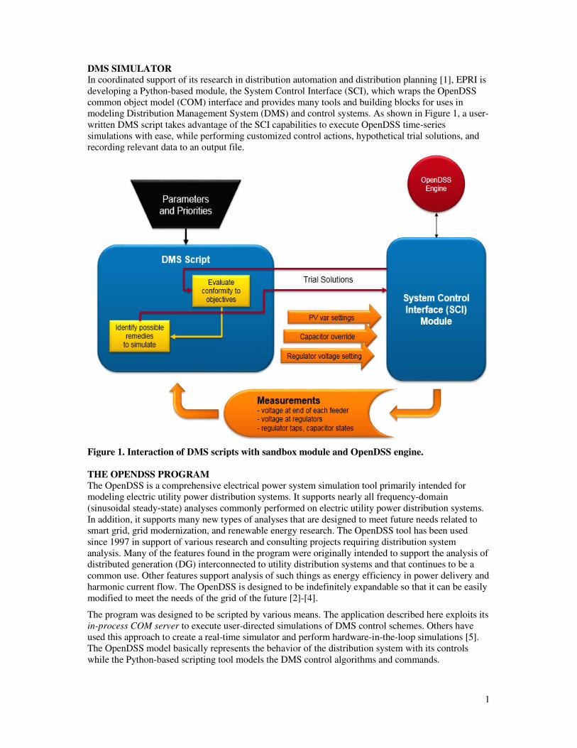
DMS SIMULATOR In coordinated support of its research in distribution automation and distribution planning [1], EPRI is
developing a Python-based module, the System Control Interface (SCI), which wraps the OpenDSS
common object model (COM) interface and provides many tools and building blocks for uses in
modeling Distribution Management System (DMS) and control systems. As shown in Figure 1, a user-
written DMS script takes advantage of the SCI capabilities to execute OpenDSS time-series
simulations with ease, while performing customized control actions, hypothetical trial solutions, and
recording relevant data to an output file.
Figure 1. Interaction of DMS scripts with sandbox module and OpenDSS engine.
THE OPENDSS PROGRAM
The OpenDSS is a comprehensive electrical power system simulation tool primarily intended for
modeling electric utility power distribution systems. It supports nearly all frequency-domain
(sinusoidal steady‐state) analyses commonly performed on electric utility power distribution systems.
In addition, it supports many new types of analyses that are designed to meet future needs related to
smart grid, grid modernization, and renewable energy research. The OpenDSS tool has been used
since 1997 in support of various research and consulting projects requiring distribution system
analysis. Many of the features found in the program were originally intended to support the analysis of
distributed generation (DG) interconnected to utility distribution systems and that continues to be a
common use. Other features support analysis of such things as energy efficiency in power delivery and
harmonic current flow. The OpenDSS is designed to be indefinitely expandable so that it can be easily
modified to meet the needs of the grid of the future [2]-[4].
The program was designed to be scripted by various means. The application described here exploits its
in-process COM server to execute user-directed simulations of DMS control schemes. Others have
used this approach to create a real-time simulator and perform hardware-in-the-loop simulations [5].
The OpenDSS model basically represents the behavior of the distribution system with its controls
while the Python-based scripting tool models the DMS control algorithms and commands.

2
USING PYTHON Python was selected as an ideal tool for DMS modeling because of its popularity for quick scripting
applications, its many included libraries, and its free, open-source nature. The Python module
implements the DMS control algorithms, which can be easily modified by the user. Because of the
growing popularity of Python as a scripting tool for distribution system analysis tools, it is expected
that distribution engineers of the future will have acquired the necessary skills to modify and maintain
model simplicity in the language.
The SCI module functionality exploits the OpenDSS COM interface, accessed via the Python package
win32com.client. The following example Python script shows some sample lines from the SCI
module to execute a time-series simulation, running each time step individually.
import win32com.client
dssObj = win32com.client.Dispatch(“OpenDSSEngine.DSS”)
dssObj.dssText.Command = “compile ‘testCircuit.dss’”
originalSteps = dssSolution.Number
for ii in range(0, originalSteps):
dssSolution.SolveSnap()
dssSolution.FinishTimeStep()
Building a DMS controller model involves adding to this skeleton by using one or more of the
following tools:
• Measuring voltage, current, and power values for control decisions
• Tracking and controlling certain element states and recording to output files
• Performing test solutions and restoring the tracked values to their original state
• Writing custom functions to take advantage of the control queue and delays
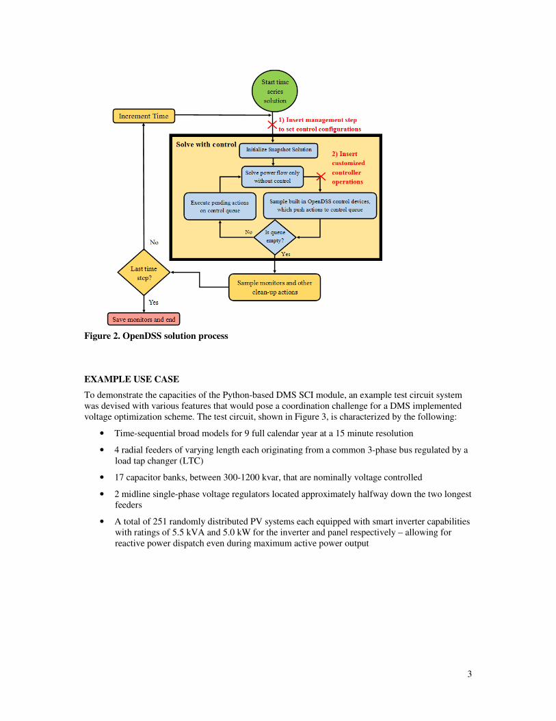
CUSTOMIZED CONTROL ACTIONS DMS control applications require custom actions to be performed at varying places within the
OpenDSS solution process, illustrated in the flow chart of Figure 2. Each time step consists of three
main parts. First, a solution with controls is completed unto convergence, shown by the large yellow
box. Next, clean-up operations are done at the end of the time step, such as sampling monitors and
updating the charge of a storage element. Finally, if there is another time step, time is incremented
and the loop begins again.
Within the Solve-With-Control block, the small blue blocks depict the controller operations in
OpenDSS. For the necessary number of control iterations, each control element is allowed to measure
the results of the power flow and push actions to the control queue for operation after a specified time
delay. When all actions on the control queue have been executed and no further ones are added, or if
the number of control iterations has exceeded the maximum, the solution with controls is considered
finished.
Figure 2 also shows the two locations, marked by red X’s, where a user may choose to insert control
actions. Point (1) is where the parameters for each control element can be set. Management tools can
use the entire large Solve-With-Control block as a testing function to determine the results for any
number of configurations under study.
To implement true customized control elements, which can push actions to the OpenDSS control
queue, iterate over each control cycle, and interact with other controllers through timing setup, the user
must insert functions at point (2) on the chart of Figure 2. This point is inside the control function and
has the benefit of customized controller iterations, but decisions here cannot use the entire yellow box
as a test unit without causing infinite recursion.
3
Figure 2. OpenDSS solution process
EXAMPLE USE CASE
To demonstrate the capacities of the Python-based DMS SCI module, an example test circuit system
was devised with various features that would pose a coordination challenge for a DMS implemented
voltage optimization scheme. The test circuit, shown in Figure 3, is characterized by the following:
• Time-sequential broad models for 9 full calendar year at a 15 minute resolution
• 4 radial feeders of varying length each originating from a common 3-phase bus regulated by a
load tap changer (LTC)
• 17 capacitor banks, between 300-1200 kvar, that are nominally voltage controlled
• 2 midline single-phase voltage regulators located approximately halfway down the two longest
feeders
• A total of 251 randomly distributed PV systems each equipped with smart inverter capabilities
with ratings of 5.5 kVA and 5.0 kW for the inverter and panel respectively – allowing for
reactive power dispatch even during maximum active power output

4
Figure 3. Test circuit for example DMS
The objectives for the DMS Example were threefold. First, all voltages must be kept within ANSI
limits at all costs. After this, a balance is sought between reduced equipment operation and
conservation voltage reduction (CVR). Because these two objectives are in tension, the approach
taken involves a penalty factor for equipment operations that allows the operator to specify the relative
value of equipment operations with respect to CVR objectives.
The Example DMS decision process performs a set of trial simulations once at each regular 15-minute
time step. When polled, the DMS executes solutions under dozens of possible control configurations
for all control elements, and chooses the one which most accurately reflects the priorities specified.
Then, once per time step, it implements these best control settings to the actual control elements for
the next 15-minute segment.
Figure 4 shows that the PV element controls in the top right and the capacitor controls in the bottom
left flatten the voltage profile compared to the upper left original plot. This allows the regulator
controls in the bottom right plot to tap the voltage down to the lower quartile of the ANSI voltage
range. Therefore, the voltage optimization control scheme, weighed against the required extra
equipment operations, succeeds in reducing the minimum system voltage, as shown in Figure 4.
An illustration of how the control scheme influences system voltages over time is provided in Figure
5. Specifically, the figure compares two different sets of control settings in the example DMS – one
which emphasizes conservation voltage reduction (CVR) at all costs and another which seeks to
achieve lower voltages while also minimizing regulator and LTC taps changes. While example values
are not tabulated in this paper, the control schemes can be evaluated in regards to the full system
benefits and impacts including system voltages, asset operations, system losses, and thermal
constraints. Note the daily variations in voltage are all but eliminated in the red plot in Figure 5,
signifying a tradeoff between regulator and LTC tapping operations and a finely regulated voltage
profile.

5
Figure 4. Voltage profiles with varying DMS settings
Figure 5. Minimum voltage over three-week DMS time series simulation

6
CONCLUSIONS EPRI’s SCI module is opening the door to streamlined experimentation with the next generation of
distribution controls. As demonstrated in the example system, this module allows execution of time
series simulations through the OpenDSS COM interface, adding customized management of
capacitors, line regulators, smart inverters, and many other circuit elements. These capabilities allow
flexibility beyond standard controls. Algorithms with timers, multiple voltage or power
measurements, calculations and prediction, coordinated interaction, memory and feedback, and even
multi-option trial solution results are all possible under this framework. As the distribution grid
modernizes, the evaluation of advanced DMS specifications will be greatly enhanced by this tool.
BIBLIOGRAPHY
[1]. Operating Distribution Systems Closer to Capacity with Distribution Automation: Modeling,
Simulation, and Planning Challenges, EPRI, Palo Alto: 2014. 3002003231.
[2]. T. E. McDermott, “An open source distribution system simulator”, IEEE PES General Meeting,
Montreal, 2006.
[3]. Control System Simulation in the Distribution System Simulator (DSS). EPRI, Palo Alto, CA:
2009. 1016035. [4]. R. C. Dugan, T. E. McDermott, “An open source platform for collaborating on smart grid
research”, IEEE PES General Meeting, Detroit, 2011.
[5]. D. Montenegro, A. Ovalle, and G. A. Ramos, "Real Time distribution system simulator Based on
OpenDSS," in Grid of the Future Symposium, Kansas City, MO, 2012.