dmt04 - ulmefors€¦ · of solar power and stirling engine technologies. the dmt04 team was ......
TRANSCRIPT


DMT04 – SOLAR POWERED STIRLING ENGINE
ii
Executive Summary
The objective of the Solar Powered Stirling Engine project was to design, make and test a solar
collector that would sustain an existing Stirling engine while automatically tracking the sun
throughout operation. This product would be proof of concept that solar radiation is a viable
method of obtaining mechanical work.
DMT04 used a Fresnel lens to focus solar radiation onto the hot end of the Stirling engine. A frame
with an adjustable pan and tilt was designed to maintain the Stirling engine at the focal point of
the Fresnel lens. A digital control system was built into the assembly to allow the continuous
tracking of the sun throughout the day.
The test results obtained by DMT04 are proof of a successful completion of the project. The
control system, with an accuracy of ±10 mm, was capable of ensuring continuous operation of the
Stirling engine, provided solar intensity exceeded a minimum of 300 W/m2. Furthermore, the
project was completed within budget, at a cost of £588.62.
This report will detail the progress of the project throughout its design, manufacture and testing
phases. A detailed discussion will be included which addresses the key results and limitations of
the project. Team DMT04 also suggests possible future developments of the project.
DMT04 – SOLAR POWERED STIRLING ENGINE
iii
Group Comment
The team consisted of four team members, all with different areas of responsibility. The team
member and their respective contributions to the project are outlined in this section.
Andrew Tan
Andrew was the designated Project Manager. His role included organising meetings internally
within the group as well as with supervisors; it was his responsibility to oversee that minutes were
written. In addition, Andrew was in charge of the control system which involved sourcing
adequate components, writing the solar tracker code and troubleshooting the system when in
service. Further, Andrew was the creator of the official website of the project and product.
Marcus Ulmefors
Marcus was in charge of the mechanical design. This role entailed verifying design decisions and
their compatibility with the assembly. Material selection for the mechanical design and the
procurement of these parts were also parts of the role. During the testing phase Marcus was
responsible for safety documentation and communication on the group's behalf in order to ensure
safe and efficient testing conditions.
Charles Peurois
Charles was the responsible for coordinating manufacture tasks and ensuring that all parts were
produced on time and to tolerance. He was also in charge of the power transmission design and
together with Andrew its integration with the control system. Charles was also responsible for
industrial contacts and contributed to the wealth of the website.
Maira Bana
Maira Bana was in charge of documentation and reporting. This role involved overseeing that
meeting minutes and reporting was of high quality and always backed up safely. Her role also
entailed delegating sections of report writing to each of the group members and overseeing the
compilation of the individual contributions to form coherent reports. Maira was also responsible
for correctness of drawings, bill of materials and costing.

DMT04 – SOLAR POWERED STIRLING ENGINE
iv
Contents 1. Introduction .............................................................................................................................................. 1
2. Background ............................................................................................................................................... 2
2.1. Stirling Engine ..................................................................................................................................... 2
2.2. Solar Power ......................................................................................................................................... 2
3. Objectives .................................................................................................................................................. 4
4. Conceptual Design .................................................................................................................................... 5
4.1. Brainstorm .......................................................................................................................................... 5
4.2. Concepts ............................................................................................................................................. 7
4.3. Concept Evaluation ............................................................................................................................. 8
4.4. Control System .................................................................................................................................... 9
5. Design Phase ........................................................................................................................................... 11
5.1. Experiments Conducted .................................................................................................................... 11
5.2. Structural and Mechanical Design .................................................................................................... 12
5.2.1. Assembly ....................................................................................................................................... 12
5.2.2. Joining Side A-frames .................................................................................................................... 12
5.2.3. Frame Support ............................................................................................................................... 13
5.2.4. Mounting of Upper Pulley ............................................................................................................. 13
5.2.5. Stirling Engine Mount .................................................................................................................... 14
5.2.6. Constant Width ............................................................................................................................. 15
5.2.7. Fixing Legs to Rotating Base Plate ................................................................................................. 15
5.2.8. Base Plate Assembly ...................................................................................................................... 15
5.2.9. Lens Clamps ................................................................................................................................... 16
5.2.10. Upper Motor Plates ................................................................................................................. 16
5.2.11. Material Selection .................................................................................................................... 17
5.3. Control System Design ...................................................................................................................... 18
5.3.1. Circuit Construction ....................................................................................................................... 19
5.3.2. Tracking Procedure ....................................................................................................................... 23
5.3.3. Control System Process ................................................................................................................. 23
5.4. Transmission Design ......................................................................................................................... 26
5.4.1. Initial Torque Calculations ............................................................................................................. 26
5.4.2. Motor Type Selection .................................................................................................................... 28
5.4.3. Motor Characteristics .................................................................................................................... 28
5.4.4. Motor Transmission System .......................................................................................................... 30
5.4.5. Details on the Belt Drive Transmission ......................................................................................... 31
5.4.6. Extension Shaft .............................................................................................................................. 32
5.4.7. Power Supply ................................................................................................................................. 33
6. Manufacture ........................................................................................................................................... 34
6.1. Design Amendments ......................................................................................................................... 34
6.1.1. Stiffening Plate .............................................................................................................................. 34

DMT04 – SOLAR POWERED STIRLING ENGINE
v
6.1.2. Rotation of Stirling Engine ............................................................................................................. 34
6.1.3. Shielding Box ................................................................................................................................. 35
6.1.4. Larger Step on Shaft ...................................................................................................................... 36
6.1.5. Rubber on Large Pulleys ................................................................................................................ 36
6.1.6. Wooden Mounts for Castors ......................................................................................................... 36
6.1.7. Second Positioning Hole in Lower Motor Plate............................................................................. 37
6.1.8. Control System Amendments ....................................................................................................... 37
6.2. Manufacturing Processes .................................................................................................................. 38
6.2.1. Frames ........................................................................................................................................... 38
6.2.2. Wooden Parts ................................................................................................................................ 39
6.2.3. Metal Parts .................................................................................................................................... 40
6.2.4. Fasteners ....................................................................................................................................... 41
6.2.5. Control System .............................................................................................................................. 41
6.2.6. Painting.......................................................................................................................................... 43
6.3. General Assembly ............................................................................................................................. 44
7. Testing ..................................................................................................................................................... 46
7.1. Performance Tests ............................................................................................................................ 46
7.1.1. No Load Speed with Lens Partially Covered .................................................................................. 46
7.1.2. Control System Update Frequency ............................................................................................... 46
7.1.3. Transient Speed Test ..................................................................................................................... 47
7.1.4. Continuous Tracking ...................................................................................................................... 48
7.1.5. Tracking System Accuracy ............................................................................................................. 48
7.2. Design Tests ...................................................................................................................................... 49
7.2.1. Time of Assembly .......................................................................................................................... 49
7.2.2. Compact Design............................................................................................................................. 49
7.2.3. Portability ...................................................................................................................................... 50
8. Expenses .................................................................................................................................................. 51
9. Discussion ................................................................................................................................................ 52
9.1. Assessment of Fulfilment of PDS Criteria ......................................................................................... 52
9.2. Management ..................................................................................................................................... 53
9.3. Results and Improvements ............................................................................................................... 56
9.4. Mass Production ............................................................................................................................... 57
9.5. Sustainability Considerations ............................................................................................................ 58
10. Conclusion ............................................................................................................................................... 59
11. Future Developments ............................................................................................................................. 60
12. References............................................................................................................................................... 61
13. Acknowledgements ................................................................................................................................. 62
Appendix A: Calculations – Stress Analysis of Frame Bars ............................................................................. 63
Appendix B: Calculations – Battery Life .......................................................................................................... 65
Appendix C: Calculations – Control ................................................................................................................. 66
DMT04 – SOLAR POWERED STIRLING ENGINE
vi
Appendix D: Calculations – Transmission ....................................................................................................... 67
Appendix E: Control Program ......................................................................................................................... 70
Appendix F: Control Flowchart ....................................................................................................................... 72
Individual Critiques ......................................................................................................................................... 73

DMT04 – SOLAR POWERED STIRLING ENGINE
1
1. Introduction
Emissions of CO2 have been a major concern in our society for decades. In 2010, global carbon
dioxide emissions reached a record high of 30.6 Gt1, which corresponds to an increase of 1.6 Gt over
emissions in 2009. The International Energy Agency (IEA) predicted that in order to avoid extreme
climate changes the annual CO2 emission level should not exceed 32 Gt by 2020. Moreover, the
Department of Energy and Climate Change targets a 25%2 increase in the fraction of renewables in
the United Kingdom’s electricity makeup between the years 2009 and 2020. At present, a vast
amount of research is being conducted in search of efficient and cost effective means of producing
energy from renewable sources. Solar energy is one of the most promising renewable sources of
energy with the average solar energy received on earth estimated to be 10,0003 greater than the
human consumption today.
In response to the current situation, this Design, Make and Test project investigates the combination
of solar power and Stirling engine technologies. The DMT04 team was given an existing Stirling
engine, designed and manufactured by students in the academic year 2009-2010 and had for mission:
"To design, make and test a solar collector capable of sustaining an existing Stirling engine through
concentrated solar power. The system should track the sun throughout the day without human input."
This report outlines the objectives, design progress and end product performance of the project. The
conceptual designs that were formulated as a response to the design brief will be presented and the
choice of the preferred concept will be justified. The detailed design of the individual components
and the assembly will also be presented. A document containing a full set of engineering drawing and
a complete bill of materials is submitted along with this report.
The manufacture of the product will be described as well as the design amendments that arose from
knowledge obtained in the manufacture and assembly processes. The final sections of the report will
outline the methods and results of the experiments conducted in order to measure and quantify the
success of the project. Tests include robustness of control system, the ability of the system to sustain
the Stirling engine and the adherence of the final design to the initial design requirements.
1 International Energy Agency (IEA). http://www.iea.org/index_info.asp?id=1959 [Accessed 02/06/2011] 2 Department of Energy and Climate Change. www.news.bbc.co.uk/1/hi/sci/tech/8150919.stm [Accessed 20/05/2011] 3 Space Future. http://www.spacefuture.com/power/introduction.shtml [Accessed 22/05/2011]
DMT04 – SOLAR POWERED STIRLING ENGINE
2
2. Background (derived from Plan Report)
In preparation for this project, the group conducted research into Stirling engines and solar power.
This section delivers the brief account of the group’s findings that was outlined in the Project Plan
Report.
2.1. Stirling Engine
The first Stirling engine was developed in 1816 by Robert Stirling, but never really reached the stage
of mass production4. Although the technology offers many advantages such as high thermal
efficiency, low operating noise and the ability to be powered by a variety of heat sources, Stirling
engines generally have low specific power, work better at constant speed and can be quite costly due
to the need for heat exchangers. The three latter reasons explain why these engines are not
extensively used. There are four kinds of Stirling engine namely Alpha (Two cylinder), Beta (Single
cylinder), Gamma (Ross Yoke) and combined engines. The principles of operation are the same but
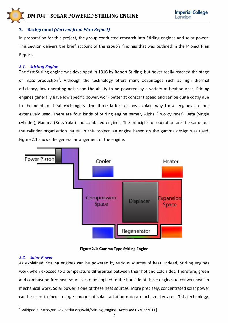
the cylinder organisation varies. In this project, an engine based on the gamma design was used.
Figure 2.1 shows the general arrangement of the engine.
Figure 2.1: Gamma Type Stirling Engine
2.2. Solar Power
As explained, Stirling engines can be powered by various sources of heat. Indeed, Stirling engines
work when exposed to a temperature differential between their hot and cold sides. Therefore, green
and combustion free heat sources can be applied to the hot side of these engines to convert heat to
mechanical work. Solar power is one of these heat sources. More precisely, concentrated solar power
can be used to focus a large amount of solar radiation onto a much smaller area. This technology,
4 Wikipedia. http://en.wikipedia.org/wiki/Stirling_engine [Accessed 07/05/2011]

DMT04 – SOLAR POWERED STIRLING ENGINE
3
being a renewable energy, offers many advantages. However, its price and its exclusivity to highly
solar exposed regions do not make it as appealing as the alternatives, and explain why it is not used
to a great extent. Nevertheless, due to the increasing need for renewable energies, and with regard
to a study by Greenpeace International, the European Solar Thermal Electricity Association and the
International Energy Agency's SolarPACES group, the global investment in concentrated solar power
could rise from 2 billion Euros in 2009 to 92.5 billion Euros by 20505. Also, thanks to the development
of new materials, namely silver polymer sheet, solar collectors could become much cheaper than the
current glass-based versions. This would translate in a price reduction of 30%6.
Figure 2.2: Solar Collector Powering a Stirling Engine7
All these facts give an idea of the potential of this technology, and this is why the project will study
how solar collectors can be associated with Stirling engines.
5 Guardian. http://www.guardian.co.uk/environment/2009/may/26/solarpower-renewableenergy [Accessed 18/11/2010] 6 Wikipedia. http://en.wikipedia.org/wiki/Concentrated_solar_power [Accessed 18/11/2010] 7 Solar Central. http://solarcentral.org/ [Accessed 19/11/2010]

DMT04 – SOLAR POWERED STIRLING ENGINE
4
3. Objectives
The brief of the Solar Powered Stirling Engine projects was to design, make and test a solar collector
that would work to sustain an existing Stirling engine by the concentration of solar radiation. Aspects
of the product design were specified, and the team were then able to lay out their objectives for the
product. The degree to which the product achieves the desired objectives would give an indication of
the success of the project.
1. The solar collector must sustain the existing Stirling engine at solar intensity of at least 600
W/m2. A manual kick-start may be required.
2. A solar tracking system should be implemented, and must work without human input.
3. The solar collector should be of a sturdy construction so as it withstand windy conditions.

DMT04 – SOLAR POWERED STIRLING ENGINE
5
4. Conceptual Design (derived from Progress Report)
The material in this section was derived from the Project Progress Report and involved identifying the
design requirements, as laid out in the product design specification, and developing concepts that are
in keeping with them. The team employed ideation techniques – conducting a brainstorming session,
sketching and evaluating conceptual designs.
4.1. Brainstorm
The team brainstorm session began with defining the key functions of the product such that the
design would meet the requirements. The “post-it” method, depicted in fig.4.1, allowed for rapid
idea generation with regards to each function, as displayed in fig.4.2 – fig.4.5.
Figure 4.1: DMT04 Post-its Brainstorm
The first design feature to consider was the system by which the solar radiation could be used to
power the Stirling engine, and this would involve directing the sunlight.
Figure 4.2: Idea Generation for a System to Direct Sunlight onto Stirling Engine

DMT04 – SOLAR POWERED STIRLING ENGINE
6
In order to track the sun, the solar collector must consist of a method for locating the position of the
sun. Figure 4.3 shows the results of the Post-its brainstorm regarding this aspect.
Figure 4.3: Idea Generation for a System to Locate the Position of the Sun
The team established that the hot end of the Stirling engine would have to be situated at the focal
point of the solar collector, which would be tracking the sun. This required generation of ideas on
how to hold the Stirling engine with respect to the moving collector.
Figure 4.4: Idea Generation for a Method of Holding the Stirling Engine with respect to the Solar Collector

DMT04 – SOLAR POWERED STIRLING ENGINE
7
As the sun follows its path the solar collector will have to follow it such that the incidence of the
radiation is perpendicular. Figure 4.5 identifies the ideas drawn up in the brainstorm for the method
of solar tracking.
Figure 4.5: Idea Generation for the Shape/Mechanism for a Solar Tracking Device
4.2. Concepts
Three conceptual designs were drawn up as a result of the ideas generated in the brainstorm. Figure
4.6 shows the three sketched concepts that were evaluated before the final selection. It was
established that in tracking the sun, the solar collector would have to move in two orientations.
Concept 1 consists of a mirrored dish as the solar collector, with the Stirling engine attached by an
adjustable arm. The motion of the dish would be driven by a geared motor in one orientation, and a
hydraulic arm in the other. The photoresistors are arranged such that the left and right resistors are
the sensors in the pan direction, controlled by the motor, and the top and bottom resistors control
the tilt by the hydraulic arm.
Concept 2 is similar to concept 1 with regards to the transmission, but employs a Fresnel lens instead
of the dish. The frame is designed to incorporate the solar collector and proposed method of
transmission.

DMT04 – SOLAR POWERED STIRLING ENGINE
8
Concept 3 also makes use of a Fresnel lens, held in a pyramidal-shaped frame. Both drive orientations
are controlled by geared/belt-driving motors, with the same photoresistor set-up as concept 2. The
Stirling engine is held stationary with respect to the lens. Both motors are mounted on the rotating
base, with the battery pack and control system.
Figure 4.6: Sketches of Conceptual Designs – (a) Concept 1 (b) Concept 2 (c) Concept 3
4.3. Concept Evaluation
Concept 1 employs a mirrored dish as the solar collector. It was established that the geometry of a
parabolic dish would define the focal distance – the more open the dish, the shorter the focal length.
The shape of the dish would have to be shallow enough to receive the incident solar radiation, but
deep enough to define a focal point in close proximity. This is a challenging aspect to concept 1,
which employs an extended, adjustable arm that holds the Stirling engine at the focal point. The
second issue with the design is that the mirrored finish of the dish should be free of defects in order
(a) (b)
(c)

DMT04 – SOLAR POWERED STIRLING ENGINE
9
to optimise the focus of radiation – this would call for a large curved mirror, which would be
expensive – an aluminium foil coating would present imperfections. The merits of concept 1 include
the tripod frame, which would be simple to implement, but would have to support a great load.
Driving the dish with a hydraulic arm is an interesting idea, which would require the team to conduct
research into the methods of implementing such a system. Rotating the base plate with a DC or
stepper motor is a sound idea, but the toothed base plate would probably be impractical to
manufacture. An alternative driving mechanism would be considered in the progression of the design
if concept 1 or 2 were to be developed. Similarly, a method of holding the motor on the rotating plate
should be recommended so as to avoid tangling.
Concept 2 consists of a Fresnel lens that will focus the radiation onto the engine. It was expected that
the accuracy of a well-manufactured lens would be similar to that of a perfectly finished mirrored
dish, but probably easier to source. The transmission methods shown as similar to those employed in
concept 1 – a hydraulic arm controlling motion in one direction, and a rotating plate in the other. The
team had deemed it suitable to contain the solar collector and Stirling engine in the same frame, so
as to be stationary with respect to one another. Furthermore, this design positions the Stirling engine
behind the solar collector with respect to the sun, allowing the incoming radiation to reach the hot
end unhindered.
Concept 3 was also drawn up with the intent of using a Fresnel lens. The benefits of Fresnel lenses
had been identified in the Project Plan Report – the team noted that Fresnel lenses lose little energy
by absorption compared with conventional lenses, are lighter and have a shorter focal length making
them practical for the task at hand. A merit of this concept is the frame, which is a well-defined
structure that would prove sturdy in operation. As with the other concepts, the Stirling engine is fixed
with respect to the lens. Concept 3 makes use of a motor, which may drive the upper frame by
gearing, belts or chains. This idea was considered more feasible than implementing a hydraulic arm.
The base plate is rotated by a geared motor, mounted on the plate itself. One issue with the
proposed design is the tripod base, which would have to be designed in careful consideration of the
centre of gravity of the contraption.
4.4. Control System
It was decided that a control system would be necessary to track the movement of the sun and
instruct the motors which way to turn. Two different types of control systems were considered –
digital or analogue. The characteristics of each system considered by the team whilst choosing
between the two systems are illustrated in table 4.1.

DMT04 – SOLAR POWERED STIRLING ENGINE
10
Table 4.1: Digital and Analogue Comparison
Parameter Digital Analogue
Use of Chip Involves the use of a chip and analogue to digital convertors to interpret data.
Does not involve the use of a chip and therefore requires no analogue to digital conversion.
Data Interpretation Data is collector by sensors and interpreted by a program written into the chip.
Data is interpreted by a series of circuit components between sensors and transducers.
Circuit complexity Relatively simple circuit. Relatively complex circuit.
Ease of troubleshooting
Troubleshooting is manageable as it simply involves making changes to the control program.
Troubleshooting is difficult as it involves making changes to the electrical circuit, and removing or inserting new components.
Cost Potentially higher because of the chip. Potentially lower.
Eventually, despite the potential higher cost of the digital system, it was decided upon to be the
easiest type of control system to implement. This was later confirmed by Dr. Rodriguez y Baena
during a meeting with him.

DMT04 – SOLAR POWERED STIRLING ENGINE
11
5. Design Phase (derived from Progress Report)
Section 5 has been derived from the Project Progress Report and outlines the design that was agreed
upon and brought to manufacture. Three key sections of the project will be presented – the
mechanical design, the control system and the transmission system. Section 5.1 provides brief
descriptions of the experiments that allowed the team to detail several design specifications.
5.1. Experiments Conducted
Three experiments were conducted in order to source a Fresnel lens of suitable performance, and
determine the overall dimensions of the solar tracker structure.
Stirling Engine Experiment
Once a decision had been made to utilise a Fresnel lens to collect and focus the solar radiation, the
required size needed to be determined. Crucially, a lens of insufficient size would not be able to
concentrate enough energy to successfully run the Stirling engine, so a comparison with supplier data
would be conducted.
Using a Bunsen burner (Usbeck, canister model 1430, nozzle model 1420) it was possible to start the
engine after the hot end had been exposed to the open flame for 85 seconds at an ambient
temperature of 13° C. The same burner was used to boil 12 oz (355 ml) of water in approximately 6
minutes. The supplier claimed that the Fresnel lens would boil 12 oz of water in 70 seconds. Although
UK sunlight would be less intense than the American conditions used by the supplier, it was agreed
that the proposed 49" spot lens could be purchased confidently.
Focal Point Experiment
The technical specifications for the Fresnel lens provided an estimate of the lens focal length of 29"
(737 mm). The exact position needed to be known since this would determine the positioning of the
Stirling engine with respect to the lens and therefore the overall frame dimensions. An experiment
was conducted positioning the lens in front of a whiteboard, pointing a perpendicular laser pointer at
different locations on the lens and tracing the focused points on the board. The experiment was
repeated at several distances from the board and the best fit was taken as the focal point. The focal
length observed conducting this experiment was 726 mm. Confirming that the two numbers agreed
within acceptable range, the result was accepted. As presented in Section 6.1.2, it was found that the
focal length data provided by the supplier was incorrect; and so were the experimental methods
employed. As a consequence the focal length had to be revised and changed to 910 mm with
implications to the final design.
DMT04 – SOLAR POWERED STIRLING ENGINE
12
Fresnel Lens Experiment
A test was undertaken in order to confirm the ability of the lens to power the Stirling engine. The hot
end of the Stirling engine was positioned at the estimated focal point and allowed to heat up. After a
few minutes the temperature difference was large enough to sustain continuous operation for more
than 60 seconds. The solar radiation at the time was approximately 300 W/m2. This result confirmed
that the lens would be sufficiently large to meet the target of sustaining the engine at solar radiation
intensity of 600 W/m2.
5.2. Structural and Mechanical Design
This section of the report outlines key structural and mechanical design features of the product and
the assembly at the point where manufacture was to commence.
5.2.1. Assembly
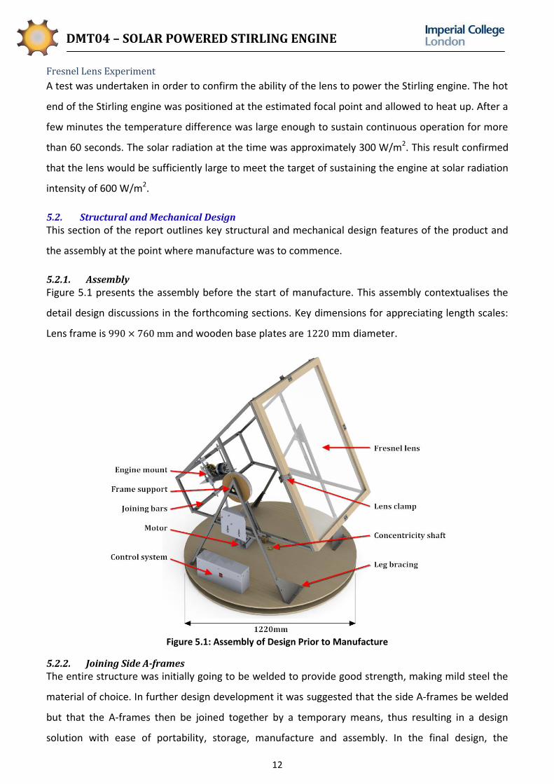
Figure 5.1 presents the assembly before the start of manufacture. This assembly contextualises the
detail design discussions in the forthcoming sections. Key dimensions for appreciating length scales:
Lens frame is and wooden base plates are diameter.
Figure 5.1: Assembly of Design Prior to Manufacture
5.2.2. Joining Side A-frames
The entire structure was initially going to be welded to provide good strength, making mild steel the
material of choice. In further design development it was suggested that the side A-frames be welded
but that the A-frames then be joined together by a temporary means, thus resulting in a design
solution with ease of portability, storage, manufacture and assembly. In the final design, the
DMT04 – SOLAR POWERED STIRLING ENGINE
13
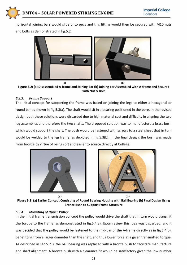
horizontal joining bars would slide onto pegs and this fitting would then be secured with M10 nuts
and bolts as demonstrated in fig.5.2.
(a) (b)
Figure 5.2: (a) Disassembled A-frame and Joining Bar (b) Joining bar Assembled with A-frame and Secured with Nut & Bolt
5.2.3. Frame Support
The initial concept for supporting the frame was based on joining the legs to either a hexagonal or
round bar as shown in fig.5.3(a). The shaft would sit in a bearing positioned in the bore. In the revised
design both these solutions were discarded due to high material cost and difficulty in aligning the two
leg assemblies and therefore the two shafts. The proposed solution was to manufacture a brass bush
which would support the shaft. The bush would be fastened with screws to a steel sheet that in turn
would be welded to the leg frame, as depicted in fig.5.3(b). In the final design, the bush was made
from bronze by virtue of being soft and easier to source directly at College.
(a) (b)
Figure 5.3: (a) Earlier Concept Consisting of Round Bearing Housing with Ball Bearing (b) Final Design Using Bronze Bush to Support Frame Structure
5.2.4. Mounting of Upper Pulley
In the initial frame transmission concept the pulley would drive the shaft that in turn would transmit
the torque to the frame, as demonstrated in fig.5.4(a). Upon review this idea was discarded, and it
was decided that the pulley would be fastened to the mid-bar of the A-frame directly as in fig.5.4(b),
benefitting from a larger diameter than the shaft, and thus lower force at a given transmitted torque.
As described in sec.5.2.3, the ball bearing was replaced with a bronze bush to facilitate manufacture
and shaft alignment. A bronze bush with a clearance fit would be satisfactory given the low number

DMT04 – SOLAR POWERED STIRLING ENGINE
14
of revolutions in service. A step in the shaft was introduced in order to maintain clearance between
stationary and moving parts.
(a) (b)
Figure 5.4: (a) First Concept of Bearing Housing and Power Transmission from Pulley to Upper Frame (b) Current design of frame support
5.2.5. Stirling Engine Mount
Three concepts were proposed for supporting and positioning the Stirling engine with respect to the
lens. Since the manufacturing and assembly would possibly result in inaccuracies it was important
that the design would allow for movement of the Stirling engine in three dimensions, should the focal
point not coincide with the position of the Stirling engine hot end.
The first concept involved a steel plate fixed to the lower rear steel bar joining the two side A-frames.
The Stirling engine could be repositioned on the plate, raised in height by adding sheet material and
clamped down when the correct position is found.
The second concept involved an additional bar on each of the side A-frames. A plate would be
fastened and held in place on two locations per side by bolts. The bolts would slide up and down
along manufactured slots to reposition the plate and the Stirling engine could be relocated on the
plate.
The third concept involved connecting the joining bars with studding, as shown in fig.5.5. Slots would
be machined along the length of the joining bars allowing for the studding to slide in one dimension.
Lindapter flange clamps would clamp the Stirling engine base plate. The flange clamps would then be
moved along the axis of the studding to reposition the height of the engine and be locked into
desired position with nuts. Movement in the third dimension would be achieved by clamping at a
different location of the Stirling engine base plate.
The third concept was finally agreed upon due to its low cost, straight forward manufacturing and
assembly. In a later revision it was suggested that U-shaped clamps be added to prevent splaying of
the joining bars upon tightening of the nuts.

DMT04 – SOLAR POWERED STIRLING ENGINE
15
Figure 5.5: Stirling Engine Mount.
5.2.6. Constant Width
In the conceptual design a "chopped pyramid" shaped frame structure was suggested. This would
save material and facilitate clamping of the Stirling engine. However, a design with constant width
was finally opted for – the horizontal rear joining bars of the upper frame would be of the same
length as those at the lens end. To begin with, joining bars at right angles would be easier; and
secondly, rotating the structure would be much easier if the side A-frames were assembled in
parallel.
5.2.7. Fixing Legs to Rotating Base Plate
Fastening the legs securely to the base plate would be important to ensure construction stability. At
first, the design featured a horizontal steel sheet welded to the underside of the legs. This steel sheet
would then be screwed into the base plate. This design was upon review changed to triangular
bracings that would support horizontal loads. In the final design, as presented in fig.5.6, flanges were
added to the bracings to secure the legs safely to the wood while providing improved stability.
Figure 5.6: Bracings Securing Legs to Rotating Base Plate.
5.2.8. Base Plate Assembly
The top base plate would be rotated by one of the motors, providing the panning mechanism.
Concentricity was first to be achieved by a wooden shaft, which was then replaced by a steel shaft
supported by a ball bearing. The ball bearing was subsequently discarded in favour of the bronze

DMT04 – SOLAR POWERED STIRLING ENGINE
16
bush bearing. Fixed castor wheels were desired to avoid swivel and difficulty of moving the structure
when changing direction often, which would be common in the tracking system. Due to an error in
the supplier item description, swivel castors were delivered which indeed caused unsatisfactory
operation of the panning mechanism. This was solved by applying strong epoxy glue at the swivel
mechanism and thereby removing the swivel effect and ensuring good rotation.
(a) (b)
Figure 5.7: (a) Load Supported by Castor Wheels, Top Base Plate Positioned by Shaft and Bush (b) Square Steel Sheets Positioning Shaft and Preventing Rotation
The stepped steel shaft would be positioned in a 4 mm thick aluminium plate with a 2 mm counter
bore, preventing the shaft from sliding out of position.
5.2.9. Lens Clamps
The Fresnel lens was supplied with a wooden frame which would be attached to the steel structure of
the upper frame. The initial concept was a simple L-shaped clamp that would be attached to the steel
frame and the wooden lens frame using self tapping screws. The L-clamps were subsequently
replaced with S-shaped clamps, shown in fig.5.8, in order to allow for mounting of an LDR. By
positioning the LDR 5 cm behind the wooden frame a shadow would be cast upon it if the lens was
misaligned with respect to the sun, facilitating accurate tracking.
Figure 5.8: Clamping Lens Frame to Steel Structure with S-clamp
5.2.10. Upper Motor Plates
The upper motor was attached to the horizontal bar of the leg structure. To ensure that the motor
pulley would be aligned with the larger wooden pulley it was decided that the motor be positioned
further away from the frame. This was achieved by inserting an aluminium bar between the

DMT04 – SOLAR POWERED STIRLING ENGINE
17
horizontal bar of the leg assembly and the motor plate. The aluminium spacer was manufactured by
cutting and milling an aluminium bar to thickness 10 mm and length 185 mm.
Figure 5.9: Upper Motor Plate.
5.2.11. Material Selection
The legs and upper frame (A-frames and bars) were all made of mild steel square tube. This decision
took into account several criteria. To begin with, the material had to be sufficiently strong. It would
also need to be available in suitable size so as to allow for the joining method described in sec.5.2.2.
Further, it was decided that the best joining method for the A-frames would be welding. As a
consequence, mild steel was chosen. The thicker square tube was of dimensions
and the thinner of dimensions . The theoretical clearance between
the bars, , would be:
When mounting the Fresnel lens and Stirling engine and taking the weight of the bars into account,
two points of interest arose in terms of bending induced stresses: (i) the diagonal bar joining the lens
side with the Stirling engine side and (ii) the mid-bar which rests on the shaft about which the tilt
mechanism works. The second moment of area, , was calculated:
(Eqn.5.1)
for the thinner bars and identically for the thicker bars. Adding the loads for the diagonal bars the
total bending moment was estimated to . The bending stress was thus calculated:
(Eqn.5.2)
This is well within the yield strength of mild steel, giving a safety factor of approximately .
Adding the loads for the mid-bar, a maximum bending moment of was expected. In
addition, a 12 mm hole was to be drill through all which would result in loss of cross section (and a
reduction in second moment of area). Further, stress concentration would be present at the hole.
The stress concentration factor was conservatively estimated to . The bending stress at the
hole was calculated:
(Eqn.5.3)

DMT04 – SOLAR POWERED STIRLING ENGINE
18
which would result in a safety factor of approximately 4 (refer to Appendix A for detailed
calculations).It is noted that the safety factors are high for this application but reducing the weight
further to optimise performance would result in more different steel thicknesses being required and
thus a higher cost of the project.
5.3. Control System Design
Having decided that the control system would be constructed with the use of a digital microcontroller
unit, team DMT04 set out to design a control system that could effectively detect the motion of the
sun and move the solar collector correspondingly. It was decided early on that in order to track the
sun effectively, it would be necessary to use a closed loop control system with feedback like the one
illustrated in fig.5.10.
Figure 5.10: Generic Closed Loop Control System Flowchart with Feedback
As can be seen in fig.5.10, a closed loop control system involves recording a measurable output
parameter and feeding it back into the controller input. The controller then interprets the fed back
data and outputs a logic signal through power amplifiers to actuators, which aim to adjust the output
parameter. Once the output has been modified by a suitable process, it is measured by the sensors
again and fed back to the controller allowing the loop to repeat itself until the desired output is
reached.
With respect to the project at hand, the desired output is the appropriate alignment of the solar
collector with respect to the sun. This will be deemed to have occurred when the Fresnel lens is
effectively focussing light onto the hot end of the Stirling engine. The control system would therefore
require a mechanism for determining the position of the sun and moving the frame to face it.

DMT04 – SOLAR POWERED STIRLING ENGINE
19
5.3.1. Circuit Construction
Figure 5.11 is a schematic detailing the construction of the control circuit. It is labelled in order to
identify the different components of the control circuit.
Figure 5.11: Completed Circuit Diagram
Examination of fig.5.11 reveals that the completed control circuit contains all of the necessary
components required of a closed loop control system as described in fig.5.10. The rest of this section
sets out to describe the decisions made between the conceptualisation of the control system to its
finalisation at the design freeze, and will elaborate on a few of the additional characteristics of the
control system.
Controller
The first component chosen was the controller. This is the component labelled in orange in both
fig.5.10 and fig.5.11. After conducting sufficient research, the team decided to use the Arduino UNO
Microcontroller, the important specifications of which are shown in table 5.1.
Table 5.1: Arduino MCU Specifications
Parameter Value
Processor ATmega328
Operating Voltage 5V
Recommended Input Voltage 7-12V
Digital I/O Pins 14 (6 of which provide PWM output)
Analogue Input Pins 6
DC Current per I/O Pin 40mA
Using the Arduino UNO presented the team with several benefits. Firstly, it is a comparatively cheap
MCU which could be purchased at a discounted price from Farnell – a supplier with which Imperial

DMT04 – SOLAR POWERED STIRLING ENGINE
20
College has an open account. It also uses an integrated development environment software (IDE) that
could be downloaded from the manufacturer’s website free of charge. The chip contains a built in
analogue to digital convertor (ADC), allowing the team to easily use it as a voltmeter able to read
input voltages and later interpret them. Provided a suitable adapter is used, it can be powered for
about 28 days by 6AA 1300 mAh batteries (Refer to Appendix B for Battery Life Calculations). It has a
5 V power output terminal which can be used to power a potential divider circuit. Finally, it has six
digital pins capable of delivering a pulse width modulated output, which is very useful for converting
a digital signal into an analogue form, and could later be used for the controlling the speed of the
motors.
Sensor
The sensor is responsible for determining the position of the sun and is highlighted in red in fig.5.10
and fig.5.11. It was decided that this could be done by placing four light sensitive sensors at extreme
ends of the lens as shown in fig.5.12. The sensors would then work in pairs, with one pair comprising
the sensors on the top and bottom, and the other pair on the left and right of the lens. This would
allow the Arduino to make a comparison between the light intensities at the top and bottom, and
between the left and right of the lens. The control system would then move the frame until the
sensors on the left and right, and top and bottom, sensed equal light intensity.
Figure 5.12: Placement of 4 Light Sensitive Transducers
In order for these sensors to be of use in the control system, it would be necessary for variations in
light intensity to produce some measurable change in the characteristics of the sensor. Two suitable
sensors were identified – the light dependent resistor (LDR) and the solar cell.
The solar cell is an active photovoltaic transducer that produces a voltage under solar radiation. The
voltage generated varies in a directly proportional manner to the light intensity incident on it. The
voltage can then be interpreted by the Arduino’s built-in ADC, converting the voltage into an integer
value between 1 and 1024 that can be interpreted by the chip.
The LDR is a passive transducer that decreases in resistance with increasing solar radiation. Unlike a
solar cell, its resistance varies in an exponential manner with respect to solar radiation. Since the LDR
does not produce any voltage of its own, it would have to be used in conjunction with an external
voltage source in a potential divider circuit. Eventually, the LDR was selected over the solar cell

DMT04 – SOLAR POWERED STIRLING ENGINE
21
because a suitable circuit comprising solar cells was found to cost approximately 10 times as much as
a suitable LDR circuit. Ultimately, the cost of employing solar cells outweighed the possible benefits.
Eventually, the potential divider circuit in fig.5.11 was designed. The letters next to each LDR in the
circuit diagram identify the position of each LDR (Top, Bottom, Left or Right). At each pin connected
to the Arduino, in higher light intensity, the voltage measured by the Arduino is approximately 0.5 V.
During lower light intensity, the voltage measured by the Arduino is approximately 5.0 V. So as not to
be limited by the non-linear nature of the LDRs, the team developed a setup to allow each LDR to
only detect light when it is coming from a certain direction. Both LDRs in each pair will sense light
simultaneously only when the solar collector is directly aligned with the sun.
Power Amplification
As will be described in sec.5.4.3, the motors chosen to drive the frames are 2 DC motors with a rated
current of approximately 8 A. It was evident that the small Arduino with a maximum output current
of 40 mA was not going to power both motors on its own. Therefore a power amplifier would be
required to interpret a logic voltage received from the Arduino and supply power to the motors. This
component is labelled in purple in both fig.5.10 and fig.5.11. Amplification would have to occur in
conjunction with a 12 V motorcycle battery, elaborated upon in sec.5.4.7.
Some of the components considered for use as power amplifiers were operational amplifiers, bipolar
junction transistors, and MOSFETs and H bridges. However, a consultation session with Dr. Rodriguez
y Baena revealed that the most ideal component to use for signal amplification was a motor driver.
Motor drivers are components designed specifically to interpret a signal in order to power a high
power motor and incorporate the usage of an H bridge.
The motor driver that the team eventually decided to use was the Sabertooth 2X10A Motor Driver. It
is a dual carriage motor driver that would allow the control of 2 DC Motors whilst allowing each
motor to draw 10 A of current continuously. The important characteristics of the Sabertooth 2X10A
are illustrated in table 5.2.
Table 5.2: Sabertooth 2X10A Specifications
Parameter Value
Input Voltage 6-24V
Output Current Per Channel 10A
Peak Output Current Per Channel 15A
The Sabertooth 2X10A has a specific mode of operation and would work in conjunction with the MCU
board. Each motor would be controlled based on the logic voltage, supplied by the MCU, and

DMT04 – SOLAR POWERED STIRLING ENGINE
22
measured at its corresponding input channel. A 2.5 V logic voltage keeps the motion stationary. A 0 V
logic voltage turns the DC motor with full power in the forward direction, and a 5 V logic voltage
turns the motor with full power in the backward direction, subject to the power source used. The
Sabertooth 2X10A also has the added benefit of having a 5 V power output terminal which can be
used to supply power to low current devices. This output terminal was initially chosen to be used to
power the potential divider circuit shown in red in fig.5.11, but was eventually decided against in
favour of using the output terminals from the Arduino, as the Arduino was revealed to offer a cleaner
voltage signal.
Delay
A delay mechanism was incorporated into the control system that would allow the motor driver to be
shut down when it was not in use. This was done in conjunction with the relay circuit labelled in blue
in fig.5.11. The motivation for the delay was to avoid unnecessary continuous tracking and thus
achieve a reduction in power consumption.
The relay circuit shown in fig.5.11 is centred on a normally open, single pole single throw, 12 V relay.
It would allow pin 13 on the Arduino board to turn on and off the motor driver as necessary. A
suitable transistor was chosen and calculations were performed to determine a suitable value for the
resistor in the circuit (Refer to Appendix C for Control Calculations).
Shutdown
The control system was designed to be completely shut down with the flick of an external rocker
switch. This external rocker switch simply shuts off the power supply to the Arduino MCU board. For
simplicity, this is the only human input that would ever be necessary with respect to the control
system and the system was designed to begin functioning the moment that the switch is turned on.
Special care was taken to ensure that no power is transmitted to any of the circuit components once
the rocker switch is turned off. For example, a normally open relay was chosen for use in the relay
circuit. This would cause the motor driver to be turned off when the Arduino is supplying the relay
circuit a LOW logic voltage through pin 13. Conversely, the use of a normally closed relay would
switch on the motor drivers as soon as the rocker switch is turned off and the Arduino stops
supplying any voltage to the relay. The situation is made worse considering that the logic voltage for
both motors would be 0 V causing the motors to continuously turn in a backward direction, putting
the people nearby at risk of injury.

DMT04 – SOLAR POWERED STIRLING ENGINE
23
Safety
Considerations were made to ensure smooth functioning of the control system as well as to protect
the control system components. Diodes were inserted in locations where surges in current were
expected in order to protect the NPN transistor in the relay circuit as shown in fig.5.11. These diodes
were inserted after a control system circuit review with Mr. Asanka Munasinghe.
In order to protect the very expensive motor driver, power connectors were used to connect the 12 V
battery to the motor driver. The reason for this is that power connectors can help to prevent the end
user from connecting the battery to the motor driver incorrectly which would definitely destroy the
motor driver. Using power connectors have the added benefit of enabling the battery to be removed
easily for charging.
5.3.2. Tracking Procedure
The effectiveness of the tracking system is largely dependent on the program written into the
Arduino board. The program would interpret the data fed into it from the four light dependent
resistors and controls the motors. In designing the tracking procedure, the team decided to first use
the Arduino to compare the voltages across the top and bottom LDR pair, and then operate the tilt
mechanism, rotating the upper frame. The Arduino would then compare the voltages across the left
and right LDR pair, and then operate the pan mechanism, rotating the upper base plate.
5.3.3. Control System Process
Throughout the progress of the project, the control system process underwent several iterations.
However, it was finally modified to exhibit the following desirable characteristics:
Ensure low battery consumption
Allow safe operation
Easy troubleshooting
Allow oscillation about desired position to account for initial overshoot
Avoid infinite loops
Eventually, a two stage control system was designed with a primary stage, and a secondary stage
which consists of the pan and tilt sub-processes. It was written to consist of two stages to enable
users of the program to understand the program more simply than if it were presented as a single,
large program. These stages are described by the flowcharts shown in the proceeding sections of the
report. The final control system was written with the Arduino IDE (Refer to Appendix E for Control
Program).
Primary Stage
The primary stage occurs according to the flowchart shown in fig.5.13.

DMT04 – SOLAR POWERED STIRLING ENGINE
24
Figure 5.13: Primary Stage Flowchart
As can be seen from fig.5.13, the first stage of the control program involves defining the variables and
the I/O pins on the MCU board. The I/O pins are defined according to the circuit shown in fig.5.11.
This program incorporates the usage of loop counters n1 and n2 to avoid infinite loops. A delay of 5
minutes has been incorporated into each cycle. This is to conserve the battery life and prevent

DMT04 – SOLAR POWERED STIRLING ENGINE
25
overheating of the system components. Overheating could prove especially dangerous since the
control system components are mounted on wood.
A comparison of this flow chart with the circuit diagram shown in fig.5.11 shows that the motor
driver has been set to maintain both motors at zero velocity before power is actually transmitted to
the motors. The blue rectangles on the flow chart activate the “pan and tilt” sub-processes that
constitute the next stage of the control program. Furthermore, the part of the flowchart within the
red box can be repeated as many times as necessary if greater accuracy is required.
Pan and Tilt Stage
The primary aim of this stage is to conduct an initial comparison between the two pairs of LDRs (the
top and bottom for tilt, and left and right for pan) and output a logic voltage to inform the motor
drivers of the type of motion to impart to the DC motors. This stage has been split up into the tilt and
pan sub-processes with the tilt sub-process occurring before the pan sub-process. A flowchart
describing the tilt sub-process is displayed in fig.5.14.
Figure 5.14: Tilt Sub-Process Flowchart
As can be seen from observing the flowchart in fig.5.14 and the circuit diagram in fig.5.11, this stage
involves comparing the light intensities on the top (pin 0) and bottom (pin 1) of the lens. Should the
difference between the voltages across the pair of LDRs be less than the tolerance voltage, x, as
defined in the primary stage of the control process, the tilt sub-process will end immediately, leading
on to the pan sub-process (Refer to Appendix F for Pan Sub-Process Flowchart). This process would

DMT04 – SOLAR POWERED STIRLING ENGINE
26
also be terminated if the loop counter, n1, incorporated to avoid infinite loops, exceeds a value of
200, indicating that the tilt sub-processes has repeated 200 times. This corresponds to approximately
10 seconds for which the motor will be turned on. These conditions are written into the control
system program by use of a two-condition while loop.
One feature that is observed in this stage is the tolerance value, x, in order to allow for certain
inaccuracies of the sensors. In the event that the voltage detected by pin 0 is larger than that of pin 1
by a value greater than the tolerance voltage, the Arduino would recognise that the light intensity is
greater below the lens, causing the motor to move down. Conversely, if the voltage detected by pin 0
is lower than that of pin 1, the Arduino would cause the motor to move up. It can also be seen that
the program allows for oscillation about the desired point in order to account for overshoot.
5.4. Transmission Design
Once the concept was selected and an initial design developed, research was carried out to select
motors and transmission systems for both axes of rotation.
5.4.1. Initial Torque Calculations
Knowing the dimensions and masses of the lens and Stirling engine, it was possible to calculate the
torques required to move the frames around both axes of motion. The assumptions made for these
calculations are given in table 5.3. The mass, length, distances to axes of rotation of the frame bars,
base plates, control system components, motors and transmission system components were
approximated according to initial concepts in order to calculate their moments of inertia (Refer to
Appendix D for Component Layout). The moments of inertia of the Stirling engine for both axes of
rotation were estimated using the measured mass and dimensions of the engine and considering it as
a circular lamina.
Table 5.3: Assumptions Made for Torque Calculation
Engine Lens Assembly
Mass (kg) 3.00 Mass (kg) 5.50 Focal length (m) 0.74
Length (m) 0.48 Length (m) 0.26 Wind speed (m/s) 8.00
Radius of rotation (m) 0.10 Incident angle (deg) 0 - 90 Width of the lens (m) 0.76
Moment of inertia (kg.m2) 0.70 Moment of inertia (kg.m2) 0.85 Height of the lens (m) 1.02
Acceleration (rad/s2) 0.63
Density of air (kg/m3) 1.29
Friction torque base plate (Nm) 4
Friction torque upper frame (Nm) 2
The moments of inertia of the mechanical structure followed directly from the geometry and
material choices and were calculated assuming rectangular bodies for the steel bars and circular body

DMT04 – SOLAR POWERED STIRLING ENGINE
27
for the base plate. They were estimated to be 0.52 kg m² and 2.78 kg m² for the vertical and
horizontal rotations respectively.
Once the moments of inertia had been estimated and assumptions on the atmospheric conditions
had been made, both the wind induced torques and inertial torques could be estimated. Firstly, the
wind force was calculated:
eq. 5.4
where the ρ is the density, v is the wind speed, h is the height of the lens, w is the width of the lens
and θ is the wind incident angle.
The associated moment is then given by:
eq. 5.5
where d is the moment arm and is the angular position.
Then, the inertial moment is simply calculated from:
eq. 5.6
where is the angular acceleration.
A frictional torque was added to each axis of motion. The frictional torque of the pan mechanism
(horizontal) was approximated as being 7 Nm due to the larger friction associated with the castor
wheels. The frictional torque of the tilt mechanism (vertical), on the other hand, was calculated to be
around 3 Nm.
The sensitivity of the assembly moment of inertia to changes in the dimensions and mass was found
to be relatively low. The inertia torque revealed to be of the same order as the wind-induced torques
and frictional torques. Also, the maximum torque requirements were found to be when the incident
wind angles are 45°. The results of these initial calculations were plotted in fig 5.15.
Figure 5.15: Drive Torque Required versus Wind Incident Angle to the Lens
0.00
2.00
4.00
6.00
8.00
10.00
12.00
0 20 40 60 80
Torq
ue
Re
qu
ire
d f
or
Ro
tati
on
(N
m)
Wind Incident Angle to the Lens (degrees)
Base Plate
Upper Frame

DMT04 – SOLAR POWERED STIRLING ENGINE
28
According to initial calculations and fig.5.15, approximate maximum torques of 11 Nm and 8 Nm
would be needed to drive the base plate and the upper frame respectively.
5.4.2. Motor Type Selection
Three different types of motors were considered for providing the necessary torque. These were
stepper motors, servomotors and DC permanent magnet motors. After some research and discussing
of the most important issues with Dr. Rodriguez y Baena, the pros and cons of the three types of
motors were summarised in table 5.4.
Table 5.4: Motor Selection Characteristics
Stepper Motors Servomotors DC Permanent Magnet
Motors
Pros Accurate
Simple transmission
Accurate
Easy to use
Affordable
Easy to use
Cons Complex system
Expensive Very expensive
Less accurate
Need a high gear ratio
The price of stepper motors and servomotors were found to be very high for this type of application.
From this research it resulted that the DC permanent magnet motors were the most practical and
cost effective solution. Since the cost of the motors and of the associated control system was a
crucial aspect, DC Permanent Magnet Motors were selected.
5.4.3. Motor Characteristics
Following the torque calculations and motor selection, some research was carried out in order to find
affordable high torque transmissions systems. The different solutions were analysed using an Issue
Based Information System (IBIS) method, shown in fig.5.16. This method enabled the team to
generate new ideas as well as see the pros and cons of each idea. This was of great help during the
preliminary design phase.

DMT04 – SOLAR POWERED STIRLING ENGINE
29
Figure 5.16: IBIS for the Transmission System
The option of having a low power motor coupled to a contact wheel transmission system was
dropped after careful review. Although being quite appealing from an expenses point of view
(expected £65 for two transmission systems), this transmission system alone would have been
difficult to implement. The need for a spring loaded motor mounting and an extremely high gear ratio
would have generated other sorts of potentially high costs. Moreover, according to the output torque
requirements and to the gear ratio achievable by using a friction drive, typical cheap low power
motors have torque/speed characteristics that would require further gearing reduction. Indeed,
typically low power motors have torque in the order of 0.01 Nm and with the size of the upper base
plate given (1220 mm diameter), an achievable gear ratio could have been 100 which only increases
the torque to 1 Nm. This is below the expected required torque of 7 Nm and in order to utilise such a
motor, a gearbox in addition to the friction drive would have to be used. The costs of the
transmission system would thus increase. Also, there would have been a high level of uncertainty on
the achievable contact surface friction forces, and as a consequence, the torque transmittable
through the wheel. Another uncertain yet important characteristic was the back-drivable torque. Non

DMT04 – SOLAR POWERED STIRLING ENGINE
30
back-drivability was considered as a key aspect of the transmission system since wind or unbalance in
the frames may otherwise cause the frames to constantly rotate and lose track of the sun. It was
crucial to ensure compatibility between the motors and the motor driver, and therefore to use
similar DC motors for both axes of rotation. However, a friction drive transmission would have been
suitable for the pan mechanism, through the base plate, only. For all these reasons, the idea of using
a low torque motor coupled to a friction wheel transmission was abandoned.
The possible solution of designing and manufacturing or buying a multiple stage gearbox used in
conjunction with a low power motor was not analysed in great detail. This was because, for low
production volumes, the costs associated with manufacturing or buying an independent multiple
stages gearbox is considerably higher than the other solutions considered.
High torque motors were also investigated. High torque motors based on the design of windshield
wiper motors were sourced and seen as practical and easy to use. The large volumes of production
make them very affordable. Other important points were that these motors are manufactured in-line
with worm gearboxes which, not only give good output torque, but also provide very high back-
drivable torque. The required characteristics of the motors made the motor selection process
relatively straightforward. These characteristics, defined thanks to initial torque calculations and
available hardware for the control system, were:
Maximise torque: > 2 Nm
Minimise price: <£30
Minimise speed: <70 rpm
Minimise rated current: <10 A
Practical rated voltage: 12 V
Maximise back-drivable torque: >10 Nm
Minimise power: <30 W
Using these requirements, the best motor was found to be the AME 214 model from AM Equipment,
an American supplier, shown in fig.5.17.
Figure 5.17: AME 214 Motor
5.4.4. Motor Transmission System
Initially, the chain and sprocket transmission system was adopted. This was due to its appealing
reliability, sturdiness and practicality to implement. However, this solution was found to be too

DMT04 – SOLAR POWERED STIRLING ENGINE
31
expensive. For that reason, it was rejected upon closer review. Table 5.5 shows the costing analysis
for the sprocket and chain system.
Table 5.5: Costing Analysis for the Sprocket and Chain Transmission
Item Supplier Price (Ea in GBP)
Quantity Sub-Total (in GBP)
¼” Pitch Sprocket (S) – 8
HPC Gears
6.84 2 13.68
¼” Pitch Sprocket (S) – 60
HPC Gears
23.38 2 46.76
¼” Pitch Chain (S) – 600 mm
HPC Gears
17.76 2 45.52 (10 delivery)
Set screws, keys ME
Stores 10 1 10
Total 115.96
Belt drives were more appealing because of their ease of implementation and low cost. Also, precise
force and friction calculations could be carried out. Indeed, it is clear, from the IBIS analysis on
fig.5.16 that belt drives offer the best trade-off in terms of cost and reliability while being easily
implementable. This system was therefore selected for the final design.
5.4.5. Details on the Belt Drive Transmission
For the belt drive system, a gear ratio of three five was selected because it offered the best cost and
force trade-off (Refer to Appendix D Figure D4 for Force-Price Comparison). The use of a timing belt
transmission system in conjunction with the AME 214 worm gear motor was supported by the
project’s supervisors.
From the motor driver specifications, the maximum current that will pass through the motors will be
10 A. According to the motor specifications (Refer to Appendix D Figure D3) it is possible to read the
corresponding maximum torque obtainable from the motor. This torque, corresponding to 6 Nm, was
used in the belt transmission calculations. All data used were taken from the HPC Gears catalogue. It
was agreed that since HPC Gears have an account with the Mechanical Engineering Department of
Imperial College and are reliable suppliers, the pulley and belt systems would be ordered from them.
Initial force analysis for the belt revealed that 13 mm wide belts were too weak in terms of tooth
shear strength. The calculations were then carried out for a 19 mm wide belt, the second available
choice from HPC. The details of the calculations for a timing belt of 3/8” pitch, 19 mm width are given
in table 5.6

DMT04 – SOLAR POWERED STIRLING ENGINE
32
Table 5.6: Force Calculations for the Pulley/Belt Transmission System
Belt Tensile Strength
Formula Used Obtained Value
[5.7]
where T is the torque, d1/2 is the pitch circle diameter,
µ is the friction factor between the wood and the belt
and α is the angle of contact
F = 485 N; which is below the maximum tensile
force (Fmax = 1260 N) applicable to the belt.
Tooth Shear Strength
Formula Used Obtained Value
[5.8]
where Mspez is the specific torque, Z1 is the number of teeth in the small pulley, Ze is the number of teeth in mesh and b is the width of the belt.
Mmax = 7.7 Nm; which is above the maximum
torque (T = 6 Nm) obtainable from the motor.
Eq. 5.7 and 5.8 come from the belt manufacturer and were deemed to be applicable. Eq 5.8 was
modified to account for the fact that there are no teeth of the large pulleys. These pulleys were
treated as being purely friction driven.
From this analysis, the 3/8” pitch, 19 mm wide timing belt was found to be appropriate for this
application. The larger pulley of the transmission system would be made out of wood because
manufacturing of the pulley could be performed in the College workshops and also because the
material cost was considerably decreased.
5.4.6. Extension Shaft
Due to the short length of the motor shaft (13 mm) and the large width of the small pulley (25.4 mm),
an extension shaft had to be manufactured. In order to induce minimal unwanted moment about the
motor shaft, the extension shaft was designed with minimum length. Both the extension shaft and
the pulley were attached with grub screws. Figure 5.18 shows a solid model of the extension shaft.
Figure 5.18: CAD Model of the Extension Shaft
DMT04 – SOLAR POWERED STIRLING ENGINE
33
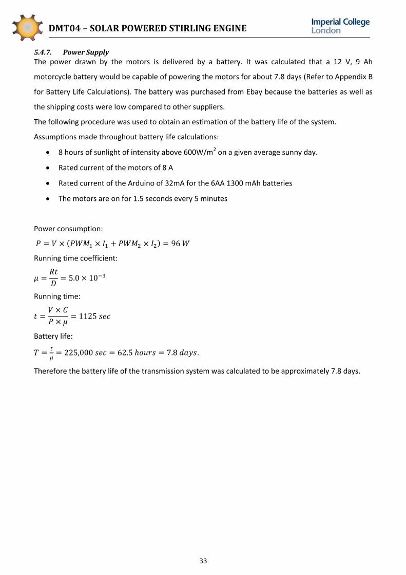
5.4.7. Power Supply
The power drawn by the motors is delivered by a battery. It was calculated that a 12 V, 9 Ah
motorcycle battery would be capable of powering the motors for about 7.8 days (Refer to Appendix B
for Battery Life Calculations). The battery was purchased from Ebay because the batteries as well as
the shipping costs were low compared to other suppliers.
The following procedure was used to obtain an estimation of the battery life of the system.
Assumptions made throughout battery life calculations:
8 hours of sunlight of intensity above 600W/m2 on a given average sunny day.
Rated current of the motors of 8 A
Rated current of the Arduino of 32mA for the 6AA 1300 mAh batteries
The motors are on for 1.5 seconds every 5 minutes
Power consumption:
Running time coefficient:
Running time:
Battery life:
.
Therefore the battery life of the transmission system was calculated to be approximately 7.8 days.

DMT04 – SOLAR POWERED STIRLING ENGINE
34
6. Manufacture
The following section outlines the design amendments and manufacturing processes employed
during the manufacture phase of the project.
6.1. Design Amendments
Shortly after the Progress Report submission the design was frozen and no further changes were
planned. However, with the advent of the manufacturing process, and more importantly that of
assembly, it became evident that several design amendments were necessary to achieve improved
performance of the product.
6.1.1. Stiffening Plate
When tension was applied to the belt connecting the upper pulleys, the plate holding the motor
became subject to a bending moment. This caused the plate to bend and the motor pulley to lose
alignment. This was solved by cutting a steel plate, bending it to an L-shape, and bolting it tightly
onto the motor plate, as shown in fig.6.1. The flanges of the new stiffening plate would now rest on
the leg assembly, holding the motor plate in position even with high tension applied.
Figure 6.1: Stiffening Plate added to Motor Plate
6.1.2. Rotation of Stirling Engine
When testing the frame assembly with the Stirling engine and Fresnel lens mounted it was found that
the focal length depended on which side of the lens was facing the sun. It was also observed that the
concentration of sunlight was not equally efficient in both orientations. The focal length of the less
efficient orientation coincided with the results obtained in the laser experiment (737 mm) and the
product specification produced by the supplier8. The focal length observed when flipping the lens was
920 mm, but the improved concentration of sunlight resulted in much more efficient heating of the
Stirling engine. There were now two strategies available. The original design could be kept which
would ensure that the focal point would be located on the Stirling engine, but it would be less
efficient. Alternatively the lens could be flipped, allowing for enhanced heating at the focal point.
However, the latter option would require a design change to position the Stirling engine further away
8 Green Power Science. http://greenpowerscience.com/ [Accessed 12/12/2010]

DMT04 – SOLAR POWERED STIRLING ENGINE
35
from the lens. It was decided that the better option was to modify the design so that a better final
result could be achieved. The Stirling engine was rotated 90 degrees and pushed backwards in its
mounts and the slots in the rear bar were extended to accommodate the Stirling engine in its new
position as shown in fig.6.2(b).
(a) (b) Figure 6.2: (a) Original Position of Stirling Engine (b) Rotated Stirling Engine
6.1.3. Shielding Box
Moving the Stirling engine further away from the lens meant it was no longer housed within the
frame structure. As a result, the criterion of user protection from burns was no longer met. To
address this increased risk of injury a shielding box was manufactured from aluminium alloy sheet.
The component fills two important functions. To begin with, it houses the Stirling engine hot end so
that a user cannot accidentally burn his or her hand when being close to the product. Secondly, the
orifice in the plate is aligned so that sunlight will only pass through the plate when the tracker is
correctly positioned. If the lens is not facing the sun correctly, the light will fall onto the aluminium
sheet. This is advantageous because it impedes the light from hitting the Stirling engine cold end,
causing the temperature difference to decrease and thus slowing down the Stirling engine. Fig 6.3
shows the installed shielding box housing the Stirling engine hot end and protecting users from
incoming concentrated solar energy.
Fig 6.3: Installed Shielding box

DMT04 – SOLAR POWERED STIRLING ENGINE
36
6.1.4. Larger Step on Shaft
After assembly of the frame it became evident that the S-clamp holding the LDR on the side opposite
the tilt motor would hit the legs upon rotation of the frame. It was decided that the best way to
account for the S-clamp would be to manufacture a shaft with a new step length of 16 mm,
compared to the previous 4 mm.
6.1.5. Rubber on Large Pulleys
When testing the upper and lower motors it was observed that there was some slippage on the large
wooden pulleys, particularly on the lower pulley since it drives a greater moment of inertia and
requires a higher torque. The use of timing belts on the smooth surface of the large wooden pulleys
resulted in a loss of effective contact area. Rather than cutting grooves to match the belt teeth it was
decided that a rubber bicycle tube be acquired, cut to adequate pieces and fastened with epoxy glue
and staples to the groove surface of the large wooden pulleys, as demonstrated in fig.6.4.
Figure 6.4: Adding Rubber to Large Pulleys
6.1.6. Wooden Mounts for Castors
Having assembled the two wooden base plates and the large bottom pulley, it was discovered that
the top base plate bent more than anticipated due to the heavy load exerted by the entire assembly.
As a consequence, the centre of the plate rubbed against the top surface of the wooden pulley when
turning. This was solved by cutting 5 mm thick wooden spacing plates which were added between
the top base plate and the individual castors.
(a) (b)
Figure 6.5: (a) Original Castor Assembly (b) Castor Assembly with Wooden Mount

DMT04 – SOLAR POWERED STIRLING ENGINE
37
6.1.7. Second Positioning Hole in Lower Motor Plate
The studding used to add tension to the lower belt was observed to cause rotation of the lower
motor plate when high tension was reached. As a consequence, alignment was lost and the
transmission would not be satisfactory. To avoid the bending effect it was decided that a second
positioning screw be added.
6.1.8. Control System Amendments
Pulse Width Modulation to Control Motor Speed
Before the team became familiar with the motor driver, it was unsure as to how effectively pulse
width modulation would be capable of controlling the speed of the motors. Whereas initially it had
been proposed to simply use a digital output of either HIGH or LOW to cause the motors to rotate in
either the anticlockwise or clockwise direction, experimentation during the manufacture phase
allowed modification of the control system program to allow the motors to turn at slower speeds, in
order to consume less power, and allow the LDRs more time to respond. It was also discovered that
the motor controlling the pan mechanism required a higher voltage to allow successful rotation than
the tilt mechanism motor. The control system program was modified to reflect these changes.
Potential Divider Circuit Resistors
Upon testing of the control system circuit, it was found that the 22kΩ resistors were too high for the
potential divider circuit as the light dependent resistors were found to exhibit a resistance of
approximately 50Ω under the light and 160Ω under the shadow. This meant that the voltage received
by the Arduino MCU under light and dark conditions were roughly the same. The situation was made
worse by the resolution of the Arduino MCU of approximately 4mV. The 22kΩ resistors were
therefore replaced with 68Ω resistors giving a voltage range of approximately 2.4-3.5V.
Multiple Loops
During calibration, it was found that a single pan and tilt sub-process per cycle was insufficient for
accurate tracking of the sun. Therefore, the control system program was modified to allow the
system to conduct a second pan and tilt sub-process within the same cycle, by looping the part of the
flowchart within the red rectangle on fig.5.13. This proved successful and allowed for much greater
accuracy in tracking.

DMT04 – SOLAR POWERED STIRLING ENGINE
38
6.2. Manufacturing Processes
6.2.1. Frames
Upper Frame
The solar collector structure incorporates two main parts which are both composed of two welded
frames. The upper frame is made of two A-shaped welded frames joined together by removable
horizontal bars. On the other hand, the lower frame comprises two welded leg frames which support
the upper frame on each side and the motor positioned on the right. Welding of the side frames was
found to offer the best trade off in terms of sturdiness and convenience. It enabled a rigid structure
while allowing the user to flat pack the product. It was crucial to cut the bars to the correct length
and angles because welding can, due to the relatively rough positioning of the structure and to
thermal effects, introduce severe deformation of the frames. To do so, all the steel bars were first
neatly cut at one end, the correct length was measured using engineering rulers or Vernier callipers
were possible. Once the lengths of the bars were marked, a mill was used to obtain a sufficiently nice
finish and to achieve the correct angle. The latter process can be seen on fig 6.6a. Welding was
carried out in two phases. First the A-frames were welded without the side plugs. Once this was done
the plugs were introduced and welded to both frames. This welding procedure was very important
because it facilitated access to crucial corners during the first phase and enabled to minimise the
effect of thermal residual strain on the position of the plugs. Fig 6.6b shows one A-frame ready for
the first welding frame.
(a) (b)
Fig 6.6: (a) Frame bar being milled to the correct size and angle and (b) A-Frame ready to be welded
Once the plugs were welded to each A-frame, an angle grinder and files were used to remove some
material on the outside of the plugs and inside of the horizontal bars until slight clearance fits were
reached. The completed upper frame could then be assembled.

DMT04 – SOLAR POWERED STIRLING ENGINE
39
Leg Assemblies
It was decided to define the position of the triangular bearing mounts once the welding of the legs
was complete. At first only one bearing mount was welded to a leg assembly. Once this was done the
other plate could be welded to the other leg frame making sure that the holes for the bush bearings
on the two mounts were at the same vertical level. This was procedure was chosen to ensure that the
effects of thermal residual strains and stresses were minimised, and thus, that the tilt axis of motion
was horizontal. As can be seen on fig 6.7a, one leg assembly possesses the bearing mount while the
other does not. The correct position of the remaining mount was then marked and the leg assembly
was sent to welding.
Once the lower frame was manufactured, the two frames were put together to perform a preliminary
check of the quality design and assembly. This is shown on fig 6.7b.
(a) (b)
Fig 6.7: (a) Legs after the first welding stage and (b) Preliminary check of the frames assembly
6.2.2. Wooden Parts
The final product contains multiple wooden parts. These were manufactured in the IDEAs Lab. The
most important wooden components are base plates and the pulleys. The processes that were
carried out are presented in the following section.
Pulleys
The pulleys were first cut to their approximate shape using a band saw and a sander. Since it was
difficult to obtain very good concentricity using these two machines only, the pulleys were fitted onto
a wood lathe and centred with a M12 bolt which was placed in the centre hole of each pulley. The
choice of using this process was reinforced by the need to make grooves for the belts. Indeed the
grooves are relatively deep and narrow which made any other processes, like sanding, difficult to
carry out. A low feed rate was used when turning the pulleys to avoid the propagation of any crack.
All other features like counter-bore bolts were realised using a pillar drill.
Base Plates
The size of the base plates restrains the choice of manufacturing processes because it is difficult to
find machines which can deal with components of diameter larger than 1 m. For that reason the

DMT04 – SOLAR POWERED STIRLING ENGINE
40
plates were manufactured using hand tools. An foot plywood sheet was cut in half before
marking and cutting circles of the correct diameter. A jigsaw was used during this process. All holes
were made using power drills and the slots for the tensioning system of the lower motor were made
by drilling two holes at the extremities and sawing in between these holes with a jigsaw. The 4 mm
square groove on the lower base plate (seen on fig.6.8a) was made using a router as shown fig.6.8b.
For safety reasons, the router was operated by Mr Gordon Addy, supervisor of the IDEAs workshop.
(a) (b)
Fig 6.8: (a) Base Plate Square Groove Feature and (b) Router Used During Manufacture
Other Wooden Parts
There are other wooden parts such as the lower tensioning block, upper motor spacer and the castor
mounts which were manufactured using a band saw, a pillar drill and a sander. Indeed, these
machines offered enough accuracy and the advantage of simple and quick manufacturing.
6.2.3. Metal Parts
Sheet Metal
The final design contains a number of sheet metal parts which were manufactured in the Student
Teaching Workshop. The parts were made of either 1 mm thick aluminium or 2 mm thick mild steel
and were cut to the required dimensions using a guillotine and, for some features, a band saw. A
metal folding machine was then used to introduce the required angles. These machines were found
to be the simplest, least dangerous and fastest way to manufacture these components. The
tolerances to be met as defined by the drawings were also found to be achievable using these
machines. Figure 6.9 shows the guillotine and bending machine used.

DMT04 – SOLAR POWERED STIRLING ENGINE
41
(a) (b)
Fig 6.9: (a) Guillotine used to cut sheet metal and (b) Bending machine used to bend sheet metal
Metal Blocks
Some components were too thick to be manufactured with the guillotine. These were namely, the
Stirling engine support plate, the aluminium plate under the base plate and the aluminium spacer for
the upper motor. These parts were principally produced using mills and pillar drills. The shaft plate –
under the lower base plate – needed, nevertheless, to be put in a four jaw chuck in order to
manufacture the counter bore.
6.2.4. Fasteners
The choice of fasteners followed directly from the design of the final product. The correct sizes were
picked. It was decided however for aesthetic reasons that socket head bolts would be preferred to
hexagon head bolts. Only the upper frame assembly comprises hexagon head bolts. These bolts
generally used for structural application were chosen because socket head bolts were not available in
the dimension needed.
Fastener choice for wooden parts was slightly different. For parts which sustain large forces the use
of a bolt on one side and a nut on the other was preferred. An example is the lower transmission
system with the lower motor plate and lower tensioning block fixed on the plywood plate by bolts
and nuts. However, most other parts were either fixed using self-tapping screws or threaded bolts
with the adequate wood inserts. The frequency of disassembling was a crucial factor for the fastener
choice. For example, the castors, which are not disassembled very often, were fastened with self-
tapping screws. On the other hand, the lens or the legs which are removed relatively often for safety
and transport were fixed with M4 bolts and corresponding M4 inserts tapped in the wood which have
a longer longevity than the wood alone.
6.2.5. Control System
The manufacture of the control system required the assembly of the circuit in accordance with the
circuit diagram in sec.5.3.1, and the writing of the control system program to match the flowcharts
displayed in sec.5.3.3. This involved attaching the components onto prototyping circuit board (PCB)

DMT04 – SOLAR POWERED STIRLING ENGINE
42
using a soldering iron and some solder. This was a fairly time consuming process and somewhat
dangerous as it was necessary to deal with molten metal. Since high temperatures of up to 400 C
were reached, soldering had to be done quickly so as not to damage any of the electrical components
purchased. Fig.6.10. shows the potential divider circuit and how the components have been soldered
onto the PCB.
Figure 6.10: Front (left) and Back (right) of Potential Divider Circuit
Once the components had been successfully soldered onto PCB, heat shrink or electrical tape was
applied around individual wires in order to protect the electrical components from external contact,
and to prevent adjacent wires from coming into contact with each other. Silicon was then applied
around key circuit components in order to protect them from contact with water. In order to further
protect the electrical components from external influence, a control system box was designed to
provide an external housing to the Arduino MCU, batteries, motor driver and relay circuit.
Several measures were taken to ensure quick assembly and disassembly. Firstly, in order to prevent
the wires from coming loose from the Arduino circuit board, they were first soldered onto a right
angle male header row, which could then be securely plugged into the corresponding female header
rows on the MCU board. Deans and bullet connectors were also used to connect wires together.
Fig.6.11. contains an image of the different connectors used in the assembly of the circuit.
Figure 6.11: Usage of Header Rows (Left), Deans Connectors (Center) and Bullet Connectors (Right) in Assembly of Control System Circuit
A wire colour convention was also defined for the different LDRs and ground in order to avoid
confusion when assembling the circuit. This convention is defined in table 6.1.

DMT04 – SOLAR POWERED STIRLING ENGINE
43
Table 6.1: Wire Colour Convention
Colour Convention
Grey Top LDR
Black Bottom LDR
White Left LDR
Red Right LDR
Brown Ground
Having already set up the hardware, the control system program was written using the Arduino IDE.
The Arduino could then be connected to the rest of the circuit and the control system could be
calibrated. Calibration of the control system was important as it allowed the team to account for the
errors and different characteristics of the control system components. This could be done fairly easily
by using the Arduino IDE to modify tolerances and incorporate zero errors in the program. Figure
6.12 is a screenshot of the Arduino IDE.
Figure 6.12: Screenshot of the Arduino IDE
A full copy of the control system program calibrated for use at a solar intensity of 850W/m2 can be
found in the Appendix E.
6.2.6. Painting
Painting was carried out using brushes. Brushes were preferred to spray paint or baked paint because
the costs associated with the two latter processes would have been excessive considering the budget
limit. All metal components were degreased using paint thinner and painted under ventilated
conditions. The wooden plates, being quite large, did not fit into the painting room of the IDEA’s
workshop. For that reason, they were painted outdoors under sunny conditions.
The hot end of the Stirling engine, reflecting a large amount of the focused light, was painted black
with a spray of High Temperature Resistant paint (stove paint, matt black). This can be seen in
fig.6.13. The hot end was sand blasted prior to being painted in order to obtain a good adhesion to

DMT04 – SOLAR POWERED STIRLING ENGINE
44
the steel. The manufacturer (ThermaCure9) specified that the paint could sustain temperatures up to
650°C. However, testing revealed that this paint could not resist the temperature experienced by the
hot end during operation.
Figure 6.13: Hot end of the Stirling engine after painting
6.3. General Assembly
Following all design amendments during manufacture and assembly phases, the final design is
presented in fig.6.14.
Figure 6.14: Assembly of Final Design
9 Thermacure. http://www.thermacure.co.uk/ [Accessed 04/06/2011]

DMT04 – SOLAR POWERED STIRLING ENGINE
45

DMT04 – SOLAR POWERED STIRLING ENGINE
46
7. Testing
In order to measure and quantify the level of success of the project, a range of tests were conducted.
The motivations for the tests undertaken are outlined in the following section as well as the
respective results and comments.
7.1. Performance Tests
7.1.1. No Load Speed with Lens Partially Covered
In order to determine the performance of the lens, it was decided to record the minimum solar
energy input required to sustain continuous operation of the Stirling engine. Rather than testing the
solar collector at different levels of solar radiation, different energy input levels were achieved by
covering parts of the lens. Testing was conducted on Friday 3 June from 12:10pm to 1:40pm. The lens
was partially covered in sections of area fraction 1/8 and the no load speed was recorded together
with the solar radiation at each instant. The speed was measured using a laser tachometer (Concorde
CT6) and the solar radiation data was taken from the Westminster station of London Grid for Learning
Weather Monitoring System.
It was found that the Stirling engine would run when 5/8 or less of the lens was covered. Figure 7.1
presents the relationship between the no load speed and the effective solar radiation intensity
( ).
Figure 7.1: Speed of Stirling Engine at Different Values of Energy Input.
7.1.2. Control System Update Frequency
In order to determine how frequently the control system would need to update the tracker position
to sustain the Stirling engine it was decided that the engine characteristics needed to be known in
greater detail. The importance of this test comes from the fact that the Stirling engine needs initial
0
100
200
300
400
500
600
700
800
900
1000
0 200 400 600 800 1000
Ro
tati
on
al s
pee
d (
rev/
min
)
Effective solar radiation intensity (W/m²)

DMT04 – SOLAR POWERED STIRLING ENGINE
47
energy input to the flywheel to run. If the engine cools down and stops human input is required to
restart it.
A performance test in operating conditions was conducted at 2:55pm on Saturday 4 June. Solar
radiation intensity was 761 W/m2 and the engine was running with no load at 700 rev/min. At this
speed the lens was covered entirely with cardboard to prevent any sunlight from hitting the Stirling
engine. This situation simulated a dense cloud or alternatively a large error in the tracker
performance. The engine was observed to slow down and eventually stop after 1 minute 45 seconds.
It was therefore decided that the delay between cycles needed to be shorter than this period in order
to minimise the risk of the engine grinding to a halt without possibility of recovery, and that the initial
proposed delay time of 5 minutes was too long.
7.1.3. Transient Speed Test
A test was conducted to determine the stability of engine speed over time. A laser tachometer was
used to measure the rotational speed. The focal point was manually positioned on the Stirling engine
hot end to ensure that the results were independent of the solar tracker performance.
Figure 7.2: Speed of Stirling Engine at No Load
As demonstrated in fig.7.2, the engine speed dropped when clouds covered the sun and the engine
accelerated when exposed to direct sunlight. It was also noted that acceleration at around 750
rev/min was slower than the acceleration at lower speeds. This is likely to be explained by the
dynamics of the system. At approximately 750 rev/min the steel frame started vibrating with large
amplitude, most likely excited by the running speed of the engine.
0
100
200
300
400
500
600
700
800
900
0 5 10 15 20 25 30 35
Stir
ling
engi
ne
spe
ed
(re
v/m
in)
Time (minutes)
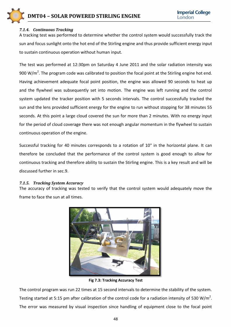
DMT04 – SOLAR POWERED STIRLING ENGINE
48
7.1.4. Continuous Tracking
A tracking test was performed to determine whether the control system would successfully track the
sun and focus sunlight onto the hot end of the Stirling engine and thus provide sufficient energy input
to sustain continuous operation without human input.
The test was performed at 12:30pm on Saturday 4 June 2011 and the solar radiation intensity was
900 W/m2. The program code was calibrated to position the focal point at the Stirling engine hot end.
Having achievement adequate focal point position, the engine was allowed 90 seconds to heat up
and the flywheel was subsequently set into motion. The engine was left running and the control
system updated the tracker position with 5 seconds intervals. The control successfully tracked the
sun and the lens provided sufficient energy for the engine to run without stopping for 38 minutes 55
seconds. At this point a large cloud covered the sun for more than 2 minutes. With no energy input
for the period of cloud coverage there was not enough angular momentum in the flywheel to sustain
continuous operation of the engine.
Successful tracking for 40 minutes corresponds to a rotation of 10° in the horizontal plane. It can
therefore be concluded that the performance of the control system is good enough to allow for
continuous tracking and therefore ability to sustain the Stirling engine. This is a key result and will be
discussed further in sec.9.
7.1.5. Tracking System Accuracy
The accuracy of tracking was tested to verify that the control system would adequately move the
frame to face the sun at all times.
Fig 7.3: Tracking Accuracy Test
The control program was run 22 times at 15 second intervals to determine the stability of the system.
Testing started at 5:15 pm after calibration of the control code for a radiation intensity of 530 W/m2.
The error was measured by visual inspection since handling of equipment close to the focal point

DMT04 – SOLAR POWERED STIRLING ENGINE
49
would be too dangerous due to the very high temperatures achieved. Having defined the centre of
the Stirling engine hot end as the datum, it was observed that all measurements were within
of the desired position. This level of accuracy ensured that the focal point was never located outside
the engine nor on the cold end. Figure 7.4 shows the results from the test.
Figure 7.4: Position of focal point relative to ideal position
7.2. Design Tests
In the Product Design Specification several constraints were enforced on the design to ensure that
the final product would be user friendly and practical. Portability, assembly and dismantling tests
were undertaken in order to confirm that the design requirements had been met.
7.2.1. Time of Assembly
In order to quantify ease of assembly it was required to measure the time taken to assemble the
structure from the individual components. Two people equipped with a hammer, an Allen key set, an
adjustable spanner and a screw driver took 25 minutes to assemble the product. Disassembly could
be done by two people with the same tools in 20 minutes.
7.2.2. Compact Design
It was desired to verify that the assembly could be easily stored whenever not in use. The product
was dismantled and the components ordered to occupy a minimum of space. Figure 7.5 shows the
space required to store the product. The base plates are 1220 mm in diameter and the maximum pile
height is 225 mm.
0
1
2
3
4
5
0 5 10 15 20 25
Erro
r (c
m)
Tracking Try
Pan
Tilt
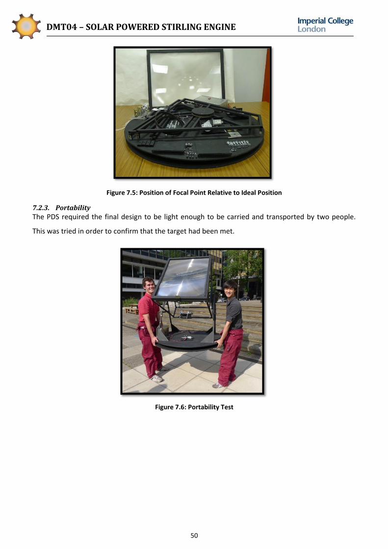
DMT04 – SOLAR POWERED STIRLING ENGINE
50
Figure 7.5: Position of Focal Point Relative to Ideal Position
7.2.3. Portability
The PDS required the final design to be light enough to be carried and transported by two people.
This was tried in order to confirm that the target had been met.
Figure 7.6: Portability Test

DMT04 – SOLAR POWERED STIRLING ENGINE
51
8. Expenses
The team achieved the goal of maintaining the project budget of £600.
Table 8.1: Table of Expenses and Parts
Item Supplier Price (Ea) (£) QTY Total incl. Shipping
Control System
LDR Farnell 327700 1.59 4 6.36
NPN Transistor ZTX688B RS Stock No. 669-7537 0.53 5 2.65
Arduino Uno MCU Board Farnell 16.26 1 16.26
Prototyping board Farnell RE520-HP – PCB 2.31 2 4.62
Diode 1000V RS Stock No. 628-9546 0.029 10 0.29
USB Printer Cable Ebay 0.99 1 0.99
Solder Farnell 1.17 1 1.17
Relay 12V DC Farnell 1.90 1 1.90
Header Row Right Angle Cool Components 1.54 1 2.14
ATMega 328 MCU Cool Components 6.00 1 6.60
Sabertooth Motor Driver 2X10A Robotbits 57.95 1 57.95
18 AWG zip wire Robot Market Place 1.99 3m 1.99
6AA Batteries Ebay 4.20 1 4.70
Desoldering Braid Farnell 1.08 1 1.08
Deans Connectors Ebay 3.47 2 6.94
Bullet Connectors Farnell 1.78 1 1.78
Bullet Connectors Jacks Hardware 4.00 2 8.00
Rocker Switch Farnell C6053ALNAE 0.84 1 0.84
DC Power plug 2.1mm Farnell 1812750 0.292 1 0.292
10A Figure 8 Zip Wire 3m Maplin 5.07 1 5.07
3.5mm Heatshrink 1m Maplin 2.09 1 2.09
Control System Total 133.712
Transmission, Motors & Battery
Geared DC Motor 12V Robot Market Place AME 214 16.56 2 67.00
3/8” Pitch Timing Pulley - 13 HPC Gears 17.18 2 41.86
3/8” Pitch Timing Belt – 647.70 mm HPC Gears 5.03 2 10.06
Epoxy Farnell 3.96 1 3.96
Set screws, keys ME Stores / RS 5.00 1 5.00
Battery 12V 9Ah - VARTA 509 014 Ebay 17.45 1 24.44
Bicycle Tube Cycle Surgery 5.00 1 5.00
Transmission, Motors & Battery Total 157.32
Frames
Fresnel Lens 1m x 0.75m Green Power Science 117.72 1 170
Exterior Ply 12 mm 8 x 4 ft Jennor Timber 27.99 1 27.99
4 pcs 31mm plate fix wheel castors Ebay 3.25 1 4.85
Steel 12m 3/4" x 3/4" x 1.5 mm + 6m 7/8" x 7/8" x 1.5 mm
Doré Metal Service 50.00 3 57.00
M10 x 1m studding ZP Farnell 1.10 1 1.10
M10 Flange Clamps x 3 Ebay 1.31 1 3.81
Paint Matt Black Farnell 4.03 1 4.03
Double Sided Foam Tape Jacks Hardware 3.29 1 3.29
Electrical Black Tape Jacks Hardware 2.59 1 2.59
Fasteners ME Stores 12.78 - 12.78
Gloves/Brushes/Cable Ties ME Stores 10.15 - 10.15
Frames Total 297.59
TOTAL 588.62

DMT04 – SOLAR POWERED STIRLING ENGINE
52
9. Discussion
The following section of the report is a discussion on how the team achieved its goals and the key
findings from the Solar Powered Stirling Engine project.
9.1. Assessment of Fulfilment of PDS Criteria
The Product Design Specification had been outlined in the Project Plan Report. Table 9.1 identifies
the key attributes of the final product recognised at the initiation of the project and the outcomes as
a method of assessing the degree to which certain objectives were achieved. Where appropriate, the
team aimed to cite quantitative data from test results.
Table 9.1: Comparison between PDS and Final Project Outcomes
Aspect Objective Criteria Outcome
Performance
Sustaining Stirling engine
Useful power output from solar collector must sustain Stirling engine when sunlight intensity exceeds 600 W/m²
Manufactured solar collector capable of sustaining Stirling engine operation under sunlight intensity of 300W/m2, exceeding expectations.
Reliability Stable and robust tracking system that effectively follows the path of the sun without user input
Control system and transmission system designed allow successful tracking of the sun to an accuracy of ±1 cm.
Temperature Operate between ambient temperatures 0<T<40°C
Not assessed in entire range. Solar collector tested working at temperature of 18 – 28°C.
Humidity Operate at 25-100% relative humidity
Not assessed in entire range. Solar collector worked in 45-75% humidity.
Cost Minimise Must not exceed £600 Total project expenditure £588.62.
Life Maximise Must exceed 20000h No suitable test available.
Size and weight Sturdy construction
Must withstand windy conditions Solar collector capable of operation under wind speeds of at least 10m/s
Easily rotatable solar collector
Must not stall tracking mechanism
Transmission system with plain bearings allow for smooth, and automatic rotation of solar collector without human input.
Portability Must be possible to carry using no more than two people
Solar collector designed to be flat-packable for easy transportation and storage. Can easily be transported by two people.
Manufacture Ease of manufacture
Minimise dependence on CNC manufacture
CNC not required for manufacture.
Availability of components
Maximise use of standard engineering components
Fresnel lens and motors imported from the USA. Sabertooth 2X10A motor driver no longer available for commercial purchase. All other components can be readily purchased in the UK.

DMT04 – SOLAR POWERED STIRLING ENGINE
53
Assembly Ease of assembly Minimise part count 273 Parts
Design Time
Minimise Finish by 21 January 2011
Design of product completed before preliminary design review on 28 January 2011. Few changes made to final design during manufacturing phase.
Patents
Ensure legality Avoid infringement
Solar collector system designed found not to infringe on any existing patents based on patent search conducted.
Aesthetics Professional Must be well-engineered
Product deemed to be aesthetically pleasing and professional.
Safety
High
House and waterproof electrical circuitry
Electrical circuitry protected from water by silicon and a protective housing. System still functioning after splash test.
Solar radiation protection for user Aluminium Heat Shield
House Stirling engine Aluminium Heat Shield
Recycling
Compliant Use recyclable materials
Bulk of frame manufactured from mild steel which is easily recycled. Wood used for based plates is bio-degradable. Rechargeable batteries used.
Maintenance
Easy
Parts must be easily accessible for replacement
Product can be easily disassembled for maintenance in 20mins
Material must be easy to clean Product can be easily disassembled for cleaning.
As can be seen from the table, most of the requirements initially identified by the team have been
met. Some of the criteria such as product life and humidity range are difficult to test and therefore to
supply numerical data for.
9.2. Management
Engineering Skills Developed
This project required the utilisation of a wide range of engineering skills. At the initial stages, it was
evident that some members of the team were especially talented in certain areas of engineering,
allowing for engineering tasks to be split accordingly. As the project progressed, team members grew
in engineering knowledge and gained practical experience, allowing the supplementation of theory
learnt in the classroom.
Firstly, the team put design skills into practice in order to arrive at a final design that was robust,
performed to specification, and was aesthetically pleasing. Ideation techniques were used in order to
better draw out and incorporate ideas from all group members. In accordance with the total design
process, market analysis was conducted and the product was truly designed with the end user in

DMT04 – SOLAR POWERED STIRLING ENGINE
54
mind, exposing the team to challenges that may be faced by an engineer working to design a product
for a customer.
In assessing the Stirling engine, it was necessary to have a command of heat transfer and
thermodynamics. This project introduced the team to a new and fairly complex Stirling cycle, which
no members of the team had previously encountered. Tests were designed to familiarise the team
with the externally combusted cycle and the engine, and determine the required conditions under
which the Stirling engine would run. Finally, the group was capable of suggesting changes which
could be made to the engine in order to allow more efficient performance.
The manufacturing section of the project allowed the team to utilise the skills developed in the ME1
manufacturing course. In fact, it called not only for the manufacture of very small, high tolerance
components, but also large structural members, which require different types of skills. Upon final
assembly of the product, analytical skills were developed in the identification, and rectification of
problems which the group had not previously anticipated during the design phase.
Design of the frame of the product exposed the team to the wide range of materials available for
purchase and use in engineering applications. It taught the team to choose materials based on
certain parameters, and the conditions under which the materials would be required to perform. The
team also learnt to conduct stress analysis on the design and to implement precautions to prevent
failure under predicted modes.
Finally, the team developed mechatronics skills in the design and construction of a control system
and belt transmission system. Team members learnt a new computer language in order to program
an Arduino Microcontroller Unit and faced several problems in the assembly of the control system
circuit. However, the team finally overcame these problems, picking up electronics skills along the
way. The team also managed to design a transmission system under budget constraint, implementing
mechanisms to prevent slippage in an economical fashion.
Publicity
The team’s enthusiasm about both the project, and the pertinence of solar energy under current
environmental conditions, is reflected in the publicity efforts that were undertaken. In the earlier
stages, the team exceeded expectations, and developed and still maintain a team website aimed at
creating an awareness of the project and increasing general public interest in concentrated solar
power systems. The website www.icsolar.co.uk contains information about the solar collector, the
techniques used throughout the project, some components used in its design, and some pictures and

DMT04 – SOLAR POWERED STIRLING ENGINE
55
videos taken during the course of the project. The team responded diligently to enquiries made by
members of the public through the website’s contact form. The team also took efforts to ensure that
the website was easily discoverable through search engines like Google by performing search engine
optimisation on the website.
The team’s publicity efforts attracted the attention of an entrepreneur by the name of Mr. Serge
Crasnianski who expressed an interest in the team’s project. Mr. Crasnianski was working on Stirling
engines at the time that this report was written and contacted the group to obtain some information
about the project and the Stirling engine used. The group assisted Mr. Crasnianski who responded by
inviting a representative from the group to the Intersolar Europe exhibition in Munich. Unfortunately,
due to constraints imposed by the project submission deadlines, the team was unable to take Mr.
Crasnianski up on his offer.
Project Management
The group tried to ensure smooth progress of the project by adhering to the project Gantt chart
which was written in the initial stages of the project. Along the way, it was soon found that other
commitments ensured that some of the targets implied by the project Gantt chart were unrealistic. It
was during these times that the group saw greatest deviation from the project Gantt chart. It was
made clear, however, that strict deadlines imposed by the college would have to be adhered to, and
all reports were submitted on time.
The team faced difficulty in following the Gantt chart during the manufacturing phase of the project.
Despite having planned in advance, the team was unable to correctly predict the impact of the
workshop timetable on the manufacturing timeline. Furthermore, the product comprises several
different components which had to be manufactured in several different workshops which added to
the complexity of the manufacture process. The team accounted for these issues by scheduling the
manufacture process so that the parts which required a certain type of machine that was in a
workshop which closed early (such as the mill), or a certain type of manufacturing process which
relied on external help (like welding), were completed earlier. This left the team with more time for
independent work in workshops which had later closing hours. In the end, the team exceeded the
scheduled manufacture completion date by approximately one week.
The team ensured smooth project progress by keeping meticulous accounts of all meeting minutes.
All files were also stored on the cloud and backed up regularly to minimise the risk of loss of work. By
the end of the project, it was safe to say that each team member cultivated an awareness of each of

DMT04 – SOLAR POWERED STIRLING ENGINE
56
the other team members working habits and styles, enabling the team to function much more
efficiently than it did at the beginning of the project.
Health and Safety
The team took health and safety very seriously throughout the progress of the project. Therefore the
project was completed without any injuries either to members of the team or the public. College
rules and health and safety guidelines were abided by and COSHH forms were filled in where
necessary. Being aware of the dangers of the project caused by the electrical transmission systems
and the high temperatures at the focal point of the lens, several precautions were taken to ensure
that the test was conducted in a safe and isolated environment, with relevant members of staff
notified, with warning signs in place to notify the general public, and with contingency plans in place
in case of safety breaches.
Budget
The team had initially anticipated some difficulty with adhering to the budget of £600. This was
overcome by importing expensive components such as the lens and the motor from the USA where
cheaper suppliers could be found, and allocating extra time for delivery. Careful budgeting allowed
the team to keep to the budget, spending a total of £588.62.
Some examples of measures taken to cut down expenditure included the manufacture of wooden
pulleys instead of purchasing large timing pulleys which would have been very costly and using LDRs
instead of solar cells. The team also made sure to purchase exactly the correct amount of material, in
suitable diameters to ensure little wastage, and used scrap metal available in the student and
research workshops where possible.
9.3. Results and Improvements
The results from sec.7.1.2. suggest that the Stirling engine will continue to run for approximately 1
min and 45 seconds from the moment the focal point is removed from the hot end. It was decided
that the tracking system should update more frequently so that an erroneous measurement would
not result in stalling the Stirling engine. The team suggests that depending on the light intensity and
the anticipated cloud coverage, delay should be adjusted to minimise power consumption without
risking stall. Delay could therefore be short on cloudy days but should not exceed 90 seconds even
under sunny conditions.
As reported in sec.7.1.3. large vibrations were observed at engine speeds around 750 rev/min. This
frequency corresponds to 12.5 Hz and is likely to be a natural frequency of the steel frame. When the
Stirling engine was running at speeds close to 750 rev/min it was clear that further acceleration was
slow and required high radiation intensity. In order to reduce the energy lost to vibration, damping

DMT04 – SOLAR POWERED STIRLING ENGINE
57
should be added to the system. Alternatively, dynamic analysis could be performed and design
changes implemented to reduce the natural frequency so that the Stirling engine could be easily
accelerated through resonance and achieve speeds exceeding 800 and 900 rev/min.
9.4. Mass Production
The current design involves several features that make it unsuitable for mass production. However,
by making suitable design amendments and introducing different manufacture processes, large scale
production could be much more attractive.
To begin with, the part count of 273 is high and could be reduced. For instance, various ad hoc
additions such as spacers, extra stiffening etc. could be reduced. Secondly, the design was developed
keeping in mind that all components were to be manufactured by team members, with the exception
of welding steel square tube that was required to be done by a technician. If the product were to be
mass produced, more automatic manufacturing methods would be available, in particular CNC
turning and milling. As a consequence, other design options would become available and priority
would turn to minimisation of human labour.
If large scale manufacturing was available, the product could be suitably redesigned to avoid the
need for welding and thus minimising the manual labour time. If welding could be avoided, the entire
frame could be made of aluminium alloy. This would not only make the frame lighter, but also make
it more resistant to corrosion, making painting unnecessary. The lighter frame would allow for the
use of smaller motors and even a weaker motor driver, reducing cost further.
One way of achieving a structure without welds would be to use thermoplastic joints onto which the
aluminium bars could be slid. With large scale production facilities, these joints could be injection
moulded and customised to accommodate the structure bars at the required angle. A suitable
thermoplastic for this application would be polypropylene.
Fig 9.1: Square Tube Connectors10
10 ESEDirect. http://www.esedirect.co.uk/p-808-square-tube-connectors-joints.aspx [Accessed 31/05/2011]

DMT04 – SOLAR POWERED STIRLING ENGINE
58
When pricing the mass produced version one would have to account for several additive price
effects. To begin with the bulk of the material used was standard metal square tubes and sheets
which can both be acquired very cheaply in large quantities. Secondly, the control system
components (the motor driver, motors, Arduino board etc.) could very possibly be negotiated to a
lower price when bought in large quantities. However, the real bottleneck would be the lens. The
Fresnel lens used in the product was a second hand lens previously used in another application. As a
consequence it was possible to procure the lens at a greatly reduced price. Since second hand lenses
become available when deemed unfit for other applications, the supply of lenses will be limited in
numbers. If lenses were to be manufactured and used directly, a much higher price would be paid
(most likely in excess of $1000). However, considering that the lens is made of acrylic (a relative
cheap material), it is very likely that a big discount could be negotiated if large quantities are ordered.
In addition, many components could be replaced. For instance, the large pulleys could possibly be
made from thermoplastic (e.g. polyoxymethylene) which would be cheaper in large scale production.
The pulleys could also be moulded to match the timing belt which would increase traction and thus
decrease the tension and torque requirements. As a consequence, less powerful motors would be
required. To save further on cost, the bronze bushes could be also replaced by polyoxymethylene
equivalents. When considering replacing metals with polymers in pulley and bearing applications,
detailed calculations must be undertaken to ensure sufficient strength.
A significant disadvantage of the current design is the low power output achieved from the Stirling
engine. At present, the system is unlikely to deliver positive net power since the motors will consume
more power than delivered by the Stirling engine. An essential part of the route to commercialisation
would be to acquire professionally built Stirling engines with high thermal efficiency.
9.5. Sustainability Considerations
Using concentrated solar power to produce mechanical work gave the project a strong emphasis on
environmental sustainability. During the progress of the project, adverse effects on the environment
were minimised by paying special attention when choosing components and materials for the
product, thus maintaining the sustainable profile. All batteries procured were rechargeable to avoid
unnecessary waste and long term additional spending. In addition, materials were ordered from
suppliers that could deliver in suitable quantities so that waste could be minimised. Where possible,
scrap materials were sourced in the Imperial College Mechanical Engineering Department, avoiding
purchase of new materials, which has been beneficial for the environment and the project budget.
The energy consumption of the control system and DC motors has been minimised by running the
system intermittently instead of continuously.

DMT04 – SOLAR POWERED STIRLING ENGINE
59
10. Conclusion
Fuelled by the current energy trends, technologies utilising solar power has been gaining increasing
pertinence. Team DMT04 set out to design a solar collector capable of sustaining an existing Stirling
engine throughout the day without human input.
Despite the relatively low solar intensity in the United Kingdom, the team succeeded in producing a
system that could successfully track the sun and sustain the Stirling engine through the usage of a
large Fresnel lens. The system included a frame, which was designed to position the hot end of the
Stirling engine at the focal point of the lens. A digital control system was designed to control both the
pan and tilt mechanisms of the frame, allowing the solar collector to track the sun.
Most of the requirements laid out in the initial product design specifications were met. Test results
showed a positive correlation between solar intensity and engine speed. It was found that a
minimum solar intensity of 300 W/m2 was required to sustain the Stirling engine. Furthermore, the
control system designed incurred a maximum focal point error of ±10 mm, and proved accurate
enough to ensure continuous operation of the Stirling engine in the absence of cloud interference.
Lastly, the team successfully adhered to the project budget of £600, spending only £588.62.
It is suggested that the possible future developments described by team DMT04 be implemented in
order to encourage the advancement of this technology.

DMT04 – SOLAR POWERED STIRLING ENGINE
60
11. Future Developments
The Solar Powered Stirling Engine project was undertaken as a continuation of a previous team’s
work creating a Stirling engine. DMT04 has therefore considered how their project could be
developed further in future DMT projects and the implications of such developments.
It was clear from the start that the Stirling engine had a low power output, so future development
could entail the procurement or construction of a more efficient Stirling engine. Efficiency could be
further improved by increasing the temperature difference between the hot and cold ends. This can
be achieved either through a reduction in temperature of the cold end or an increase in temperature
of the hot end. The cold end of the engine could be cooled by forced convection, enhanced finning or
installation of a water cooling system. Methods for attaining a higher temperature of the hot end
through the minimisation of radiation and convective heat losses should also be considered by future
groups.
For future development, other Stirling engine types could be investigated. In addition to the alpha
and beta models introduced in sec.2 one might consider the Free-piston Stirling engine (FPSE)11. In
contrast to the gamma configuration Stirling engine used in the project, the FPSE has a piston which
drives a linear alternator as opposed to a flywheel. With fewer moving parts, the FPSE does not
require lubrication and high-pressure seals, and friction and wear are substantially reduced.
With regards to the control system, it is recommended that solar cells, which could be used instead
of light dependent resistors, be experimented with. These are active transducers which use the
photovoltaic effect to produce a voltage which varies linearly according to light intensity. These solar
cells could possibly even be used to power the control system, eliminating the need for batteries and
charging, making it truly self sustaining.
The Stirling engine is not self starting, and requires a kick to impart an initial momentum to the
engine. It is feasible to connect a DC machine to the flywheel of the Stirling engine. It can then, be
used in conjunction with the Arduino MCU to provide the initial kick to the Stirling engine, and as a
generator to create usable electrical output when the Stirling engine is running continuously.
Furthermore, excess power output could be stored for later consumption by for example recharging
batteries.
11 Lane,N. W. & Beale, W. T. (1996) A Free-Piston Stirling Engine-Alternator for Solar Electric Power. Sunpower, USA.

DMT04 – SOLAR POWERED STIRLING ENGINE
61
12. References
[1] International Energy Agency (IEA). http://www.iea.org/index_info.asp?id=1959 [Accessed
02/06/2011]
[2] Department of Energy and Climate Change. www.news.bbc.co.uk/1/hi/sci/tech/8150919.stm
[Accessed 20/05/2011]
[3] Space Future. http://www.spacefuture.com/power/introduction.shtml [Accessed 22/05/2011]
[4] Wikipedia. http://en.wikipedia.org/wiki/Stirling_engine [Accessed 07/05/2011]
[5] Guardian. http://www.guardian.co.uk/environment/2009/may/26/solarpower-
renewableenergy [Accessed 18/11/2010]
[6] Wikipedia. http://en.wikipedia.org/wiki/Concentrated_solar_power [Accessed 18/11/2010]
[7] Solar Central. http://solarcentral.org/ [Accessed 19/11/2010]
[8] Green Power Science. http://greenpowerscience.com/ [Accessed 12/12/2010]
[9] Thermacure. http://www.thermacure.co.uk/ [Accessed 04/06/2011]
[10] ESEDirect. http://www.esedirect.co.uk/p-808-square-tube-connectors-joints.aspx [Accessed
31/05/2011]
[11] Laser Physics. http://www.laserphysics.co.uk/laser_beam_dump.html [Accessed 26/05/2011]
[12] Lane,N. W. & Beale, W. T. (1996) A Free-Piston Stirling Engine-Alternator for Solar Electric
Power. Sunpower, USA.

DMT04 – SOLAR POWERED STIRLING ENGINE
62
13. Acknowledgements
Team DMT04 would like to acknowledge the following people for their contribution to the successful completion of the project:
Dr. Ricardo Martinez-Botas
Mr. Harminder Flora
Mr. Gordon Addy
Mr Paul Woodward
Mr Dave Murphy
Mr. Asanka Munasinghe
Dr. Fred Marquis
Dr. Ferdinando Rodriguez y Baena
Mr. David Sweeney
Mr. Mark Holloway
Mr. Dave Robb
DMT12_2010

DMT04 – SOLAR POWERED STIRLING ENGINE
63
Appendix A: Calculations – Stress Analysis of Frame Bars
Thinner square tube
Bar dimensions:
Cross sectional area:
Weight of bars:
Second moment of Area:
Thicker square tube
Bar dimensions:
Cross sectional area:
Weight of bars:
Second moment of Area:
Diagonal Bars
Length of bars:
Weight of steel frame:
Lens and Stirling Engine:
Total weight:
Length of load carrying bar:
Force per load carrying bar:
Maximum bending moment:
Second moment of Area:
Maximum stress:
It is proposed that a 12 mm hole is drilled through the bar. Stress concentration factor for the hole is estimated at and a new second moment of area is calculated.
Second moment of Area:
Maximum stress:
A-bars (midpoint bars)
Bar length of front frame half:
Bar length of rear frame half:
Weight of Lens:
Weight front half of frame:
Weight of Stirling Engine:

DMT04 – SOLAR POWERED STIRLING ENGINE
64
Weight rear half of frame:
Force per load carrying bar:
Maximum bending moment:
Second moment of Area:
Maximum stress:

DMT04 – SOLAR POWERED STIRLING ENGINE
65
Appendix B: Calculations – Battery Life
Assumptions made throughout battery life calculations:
8 hours of sunlight of intensity above 600W/m2 on a given average day.
Discharge current of 32mA for the 6AA batteries
6 x AA Batteries
Battery life of AA Battery =
Total Battery life of 6AA Batteries = 7
Discharge time of 6AA batteries per day =
Battery life in days =

DMT04 – SOLAR POWERED STIRLING ENGINE
66
Appendix C: Calculations – Control
Fig C.1: Circuit Diagram for Determination of R1 Resistor
Relay coil resistance,
By Ohm’s law, Vr=IR
Current that will flow through relay,
Transistor forward current gain,
At 5V, 2.0mA,
Base current,
From E12 series, use a 15kΩ resistor.

DMT04 – SOLAR POWERED STIRLING ENGINE
67
Appendix D: Calculations – Transmission
The figures below show the components and variable considered when performing initial torque
calculations.
Figure D1: Torque Analysis of the Upper Transmission System
Figure D2: Torque Analysis of the Lower Transmission System

DMT04 – SOLAR POWERED STIRLING ENGINE
68
Figure D3 shows the specifications of the motors that will be used.
Figure D3: Motor AME 214 Specifications
The different models of timing pulleys available from HPC gears were used to obtain the graph below.
The graph shows the maximum tensile force in the belt and the price of the transmission system as a
function of the gear ratio (between 2 and 4) and of the pulley diameter (between 30.32 mm and
54.57 mm).
Figure D4: Maximum Tensile Force in the Belt and Price of one Transmission System versus the Gear Ratio for Various Small Pulley Diameters
0
5
10
15
20
25
30
0.00
100.00
200.00
300.00
400.00
500.00
600.00
700.00
800.00
2 3 4
Pri
ce (
Po
un
ds
Ste
rlin
g £
)
Forc
e (
N)
Gear Ratio
Force
Price
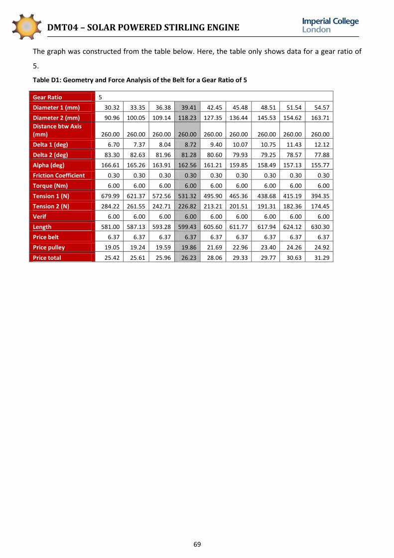
DMT04 – SOLAR POWERED STIRLING ENGINE
69
The graph was constructed from the table below. Here, the table only shows data for a gear ratio of
5.
Table D1: Geometry and Force Analysis of the Belt for a Gear Ratio of 5
Gear Ratio 5
Diameter 1 (mm) 30.32 33.35 36.38 39.41 42.45 45.48 48.51 51.54 54.57
Diameter 2 (mm) 90.96 100.05 109.14 118.23 127.35 136.44 145.53 154.62 163.71
Distance btw Axis (mm) 260.00 260.00 260.00 260.00 260.00 260.00 260.00 260.00 260.00
Delta 1 (deg) 6.70 7.37 8.04 8.72 9.40 10.07 10.75 11.43 12.12
Delta 2 (deg) 83.30 82.63 81.96 81.28 80.60 79.93 79.25 78.57 77.88
Alpha (deg) 166.61 165.26 163.91 162.56 161.21 159.85 158.49 157.13 155.77
Friction Coefficient 0.30 0.30 0.30 0.30 0.30 0.30 0.30 0.30 0.30
Torque (Nm) 6.00 6.00 6.00 6.00 6.00 6.00 6.00 6.00 6.00
Tension 1 (N) 679.99 621.37 572.56 531.32 495.90 465.36 438.68 415.19 394.35
Tension 2 (N) 284.22 261.55 242.71 226.82 213.21 201.51 191.31 182.36 174.45
Verif 6.00 6.00 6.00 6.00 6.00 6.00 6.00 6.00 6.00
Length 581.00 587.13 593.28 599.43 605.60 611.77 617.94 624.12 630.30
Price belt 6.37 6.37 6.37 6.37 6.37 6.37 6.37 6.37 6.37
Price pulley 19.05 19.24 19.59 19.86 21.69 22.96 23.40 24.26 24.92
Price total 25.42 25.61 25.96 26.23 28.06 29.33 29.77 30.63 31.29

DMT04 – SOLAR POWERED STIRLING ENGINE
70
Appendix E: Control Program
//Define I/O pin positions int OutT=11; //Output Tilt - Motor Driver S1 int OutP=10; //Output Pan - Motor Driver S2; int OutRe=13; //Output to Relay Circuit
//Define initial values int BaseU=0;//Set initial LDR readings to 0 int BaseD=0; int BaseL=0; int BaseR=0; int DifT; //Define integer for difference between top and bottom int DifP ; //Define integer for difference between left and right int tol=1; //tolerance value (can take any value between 1 and 1024) int n=1; //loop counter for main loop int n1=1; //loop counter for pan int n2=1; //loop counter for tilt int Tiltz=-144; //-ve to make spot go up int Panz=35; //+ve to make spot go left int Ta=157; //PWM for tilt int Tb=97; int Pa=214; //PWM for pan int Pb=40; void setup() pinMode(A0,INPUT);//Define analogue pins as input pinMode(A1,INPUT); pinMode(A2,INPUT); pinMode(A3,INPUT); pinMode(OutT,OUTPUT); //Tilt output pinMode(OutP,OUTPUT); //Pan output pinMode(OutRe,OUTPUT); //Relay output void loop() n=1; //Reset loop counter while (n<=2) //repeat 2 times n++; //adds 1 to loop counter n1=1; //Reset loop counters n2=1; analogWrite(OutT, 127); //PWM takes values between 1 and 256 analogWrite(OutP, 127); digitalWrite(OutRe, HIGH); //Relay on //tilt mechanism BaseU=analogRead(A0); //Reads in UP analogue voltage (this is a number between 0 and 1024) BaseD=analogRead(A1); //Reads in DOWN analogue voltage DifT=BaseU-BaseD;

DMT04 – SOLAR POWERED STIRLING ENGINE
71
while(n1<200 && (abs(DifT)>tol) ) //While loop with 2 conditions. Controls tilt n1++; //Increase loop counter by 1 BaseU=analogRead(A0); BaseD=analogRead(A1); DifT=BaseU-BaseD-Tiltz; if (DifT > 0) // Sun on top < Sun on Bottom analogWrite(OutT, Ta); delay (50); else analogWrite(OutT, Tb); delay (50); analogWrite(OutT, 127); //Reset pin 11 to 0rpm //pan mechanism BaseL=analogRead(A2); //Reads in LEFT analogue voltage BaseR=analogRead(A3); //Reads in RIGHT analogue voltage DifP=BaseL-BaseR; while(n2<200 && (abs(DifP)>tol) ) //While loop with 2 conditions. n2++; BaseL=analogRead(A2); BaseR=analogRead(A3); DifP=BaseL-BaseR-Panz; if (DifP > 0)//Sun on left < Sun on right? analogWrite(OutP, Pa); delay(50); else analogWrite(OutP, Pb); delay(50); analogWrite(OutP, 127); //Reset pin 10 to 0rpm digitalWrite(OutRe, LOW); //Relay off. No power to driver. digitalWrite(OutP, LOW); //No logic output from pin10 digitalWrite(OutT, LOW);//No logic output from pin11 delay(100000); //delay till next loop in milliseconds

DMT04 – SOLAR POWERED STIRLING ENGINE
72
Appendix F: Control Flowchart
Figure F1: Pan Sub-Process Flowchart

DMT04 – SOLAR POWERED STIRLING ENGINE
73
Individual Critiques
Andrew Tan
Participating in the DMT project has been a valuable experience for me, and I thoroughly enjoyed
being a member of Team ICsolar. Despite already having been acquainted with the other members of
my 4-man team, it took a while before we each came to an understanding of each other’s working
styles. The project we chose was sufficiently challenging to keep us occupied, and solar energy is a
topic of particular interest to me, having come from Singapore – a country which has spent large
amounts of money on solar energy research. Throughout the project, the group not only formed
bonds in school whilst working on the project, but whilst engaging in social activities outside of
school.
The team did not adhere strictly to the minimum requirements of the project, but saw it as an
opportunity to practise skills which could prove useful during our future careers. We sought to create
publicity for the project by creating a team website, wrote to magazines to try and get our project
published, and looked for sponsors. The actual project was conducted as professionally as possible,
as if working for a company, and all meetings were taken very seriously. I also cherished the fact that
our group was given a fair amount of independence from the supervisors to try out our own ideas.
This project also gave us the opportunity to develop the important skill of being able interact with
people outside of the college.
At the beginning stages of the project, it was decided that I should undertake the role of project
manager. This was one of the easiest projects that I have had to manage as each member of my
group was well aware of their individual roles, acted extremely responsibly, and needed little
encouragement to achieve the goals of the project. However, as always, it is difficult to manage a
team of peers and it took a while before I felt that everybody was truly comfortable with their place
within the group. This is a useful skill which this project has helped me to improve. As project
manager, it was my duty to organise meetings, manage the budget, try to mitigate risks, and ensure
that the project proceeded in a smooth and timely fashion. Despite the fact that every group member
was capable of making decisions on their own, I found that it was still important to have a project
manager that could tie them all together.
After some time, group members became confident enough to voice their opinions. I participated in
heated discussions with other group members concerning key aspects of the project, and found that
these discussions were good for addressing conflicting views and essential to project progress. Good
project management did not require that all group members agreed completely on every aspect of
the project, but that some group members were mature enough to allow ideas which they may
initially not have supported to come to fruition. In order to be effective, it was important to always

DMT04 – SOLAR POWERED STIRLING ENGINE
74
pick the correct person for the job, and not assign roles to people that they were not confident in,
even if this required some people within the group to assume a slightly higher workload than others
during certain stages in the project. Ultimately, however, I found that every person contributed
practically equally to the success of the project.
If I were to perform the project again, I would like to ensure better time management as this is
something which I feel I could have orchestrated better. During some critical stages of the project,
time was lost when all group members were called together for meetings which, despite having a
clear purpose, did not require that all group members were present, and in which some group
members did not have a role to play. This was ideally to allow every group member to feel that they
were participating in the project. However, this practice actually wasted time which idle group
members could have better spent elsewhere. This could be avoided by splitting up tasks properly,
allowing each group member to complete a certain amount of work independently, and organising
meetings only for consolidation.
Overall, I would say that this project has not only been useful for the development of my technical
engineering skills. It has been quite enjoyable, and has been an excellent platform for the
development of competencies that will eventually be used in my future career.
Maira Bana
The success of a project can be attributed to many factors, be it good design, skilled manufacture or
completeness in approach; but centre to all of these is a strong team, a team that works as a whole
and as individuals, with members who are in sync but continue to challenge one another. DMT04
consisted of four enthusiastic and diligent students, making for a strong group dynamic and a very
enjoyable project.
The project was chosen after the team formed, and it was clear that all members were excited to
work on a solar-related project. The idea of continuing the work of last year’s DMT Stirling Engine
project was appealing due to the quality of the product.
From the start, the team realised that organisation would be key to achieving our goals. We identified
four positions of responsibility and assigned them to members according to individuals’ strengths and
interests. This meant that all aspects of the project could be managed effectively by different
members, while being overseen by the Project Manager. We were keen to maintain organisation
through the recording of Meeting Minutes, a task that was shared equally between all team
members.
The team aimed to never compromise on quality, and this was, as anticipated, difficult at times.
However, on reflection, it seems that the team found the most elegant and feasible solutions to

DMT04 – SOLAR POWERED STIRLING ENGINE
75
problems encountered. Early on in the project, the team was concerned about exceeding the budget,
but careful reconsideration and sourcing of items meant staying within the cost limit.
The execution of the project could have been improved with respect to timeliness. Whilst we had
planned our timings, and succeeded in meeting deadlines, there was a phase during the project when
we were pressed for time.
It was clear from the start that there would not always be agreement within the team, but these
situations were managed well. Contestable decisions were not made without discussion, and this
made for comfortable relationships between the team members.
My role within the team was Editor-in-Chief. This involved leading the team in the writing of reports
and poster design. It was important to ensure equal designation of tasks, and to then edit reports as
a whole to ensure they read well. Due to health and safety reasons, I played no part in the
manufacture of the product other than assisting in the building of the control system. The other
three members of the team therefore had a lot of work to do. Without permission to enter the
workshop, I found that I became slightly out-of-touch with changes in design and the progress of the
team. In the future, I would therefore aim to have better communication with the team during the
manufacturing phase.
The enthusiasm of the team was evident throughout the project. The ICSolar website is the perfect
example of how we aimed to publicise our work and spark an interest in solar technologies in others.
Looking back, I can say that it has been a pleasure working on such an interesting and exciting
project, with such talented individuals and such a strong team.
Charles Peurois
The Design Make and Test project has been very beneficial to me. The project enabled me to improve
my organisational, project management and time management skills. In my opinion, the key reason
for the success of the project was the fact that goals, roles and responsibilities were clearly outlined
from the start of the project. The early organisation of the project was indeed very advantageous
since all the important decisions were drawn from a solid foundation. Another very important
characteristic of team ICSolar was that the work assigned to each team member corresponded to the
field in which they were most motivated, experienced and likely to perform well. The different
working styles and backgrounds of each member allowed for a wide range of opinions. Group
discussions were indeed very interesting and enriching. All members felt comfortable explaining what
their thoughts were and were keen on contributing to discussions.
I found the engineering discipline of the project really interesting, especially because renewable
energies and solar power are becoming increasingly important in today’s society. The work load was
satisfying and I truly enjoyed participating in this project.

DMT04 – SOLAR POWERED STIRLING ENGINE
76
My role in the team was manufacturing manager. As such, a big part of my responsibilities was to
ensure that the designs agreed upon during meetings were sensible and practical from a
manufacturing point of view. I also had to supervise the manufacturing stage of the project. I found
that role very exciting because the integration of design and manufacture has interested me for a
long time. However, manufacturing is not the only area in which I contributed and I think that is why
the DMT project is a very enriching experience. I also had the opportunity to assist other members in
their tasks, such as CAD modelling, and to work on creating the website for our project. Furthermore,
it enhanced my knowledge in engineering, especially in the fields of solar energies and mechatronics.
This task diversity made my experience much more rewarding and enjoyable.
In my next group project I would like to insist more on keeping up with the timeline of the project.
Even though this DMT was planned reasonably and the required goals were achieved, I felt at some
times in the project that the team was behind schedule or that valuable time was lost. This was
particularly obvious before taking an important step forward, like starting manufacturing. Although
the timeline was clearly defined by the Gantt chart at the beginning of the project, the use of such
charts could have been optimised and more regular reference to this timeline would have ensured a
smoother operation of the project. Another aspect to which I would pay more attention in the future
is to perform preliminary test of important parts delivered by suppliers. Since there is always a
degree of uncertainty in the quality or reliability of ordered components, it is important to verify that
core components comply with the specifications or expected values so that no surprises are found
after manufacturing.
In summary, this really was practical experience of what a professional project might be like. I
sincerely believe that it has prepared me well for some challenges that I might come across at the
start of my professional career or postgraduate education.
Marcus Ulmefors
The management of the project evolved naturally without the need of employing an artificial
structure or enforcing strict roles. Having said that, every area of the project was the responsibility of
one of the team members. No task fell between two chairs or was forgotten, which can happen if
responsibility is unclear. However, no team member was ever left completely alone with a large
portion of the project. There was always a second person with deep knowledge of that section that
could be a discussion partner and develop ideas. No major problems were encountered in the
internal management of the group, partly because the team members knew each other beforehand
and knew what would be expected from them. One person being ultimately responsible but having
secondary support has worked very well and is something I will use in the future. With team
members taking different electives throughout the year it sometimes proved difficult to plan

DMT04 – SOLAR POWERED STIRLING ENGINE
77
meetings with the group and both supervisors present. However, the quality of the work never
suffered since all team members were always eager to contribute to the development of the project.
This is perhaps best exemplified in the creation of the team website which was not part of the
objectives but was both fun and incidentally resulted in promising industrial contacts.
Personally, my largest area of responsibility was initially the mechanical design. This involved material
selection, solid modelling, dimensioning and creation of drawings. All team members were of course
heavily involved in both the conceptual design and detail design phases, but it was my responsibility
to provide information on whether materials could be procured quickly and within budget. Secondly,
the combination of having spent 10 weeks on a UROP placement last summer in addition to my role
as a student representative proved useful because of the knowledge acquired about the Department
during this time. Having direct connections with academics, administrative staff and technicians
saved time since we would know quicker who to address when a question arose. This was particularly
useful towards the end of the project when planning time, location and procedures of testing.
At the end of the project we found ourselves in a rush because we were dependent on sunny days to
conduct our testing. The London climate obviously would not provide a long period of uninterrupted
sunshine and we were probably lucky to get some good sun hours on suitable dates at the very end
of the project. Perhaps we should have tried to have a bigger margin of error to account for a long
streak of clouds and rain. An additional lesson learnt came from the focal length surprise. Although
having conducted a test that confirmed the manufacturer's description, we found ourselves having to
reconsider the frame design which wasn't very flexible since it was already welded. A good solution
was found but next time I will definitely be more careful and test more meticulously the data
provided by suppliers.
This project has run very smoothly in terms of management (although there have been many
engineering challenges), very likely because all team members knew each other beforehand. All team
members have been very comfortable voicing their opinions which has benefitted the progress of the
project. Looking back at the project from start to finish, I am very impressed with what has been
achieved. The project's very open brief gave a lot of design freedom at the early stages. Having seen
the diverging concepts come together to form a complex system of mechanics, transmission,
mechatronics and programming that actually works and meets set targets has been greatly
rewarding. In coming projects the most important thing to keep in mind will be to be ready for more
difficult group dynamics and the fact that the luxury of choosing my colleagues cannot be taken for
granted.