dn-24 series data sheet 04-04 - wireless | murata ... dn-24 series 2.4 ghz serial modems provide a...
TRANSCRIPT
DN-24Series
Rating Value Units
Power Supply Input Voltage Range -0.5 to +24 V
Non-Operating Ambient Temperature Range -40 to +85oC
DN-24 Absolute Maximum Ratings
DN-24 Specifications
Characteristic Sym Notes Minimum Typical Maximum Units
Operating Frequency Range 2406 2475 MHz
Hop Dwell Time 8 100 ms
Number of RF Channels 15 or 24
Modulation FSK
RF Data Transmission Rate 250 kbps
Receiver Sensitivity @ 10-5
BER -100 dBm
EIRP RF Output Power Level, 2 dBi Antenna 100 mW
Optimum Antenna Impedance 50 Ω
RF Connection RSMA Coaxial Connector
Network TopologiesPoint-to-Point, Point-to-Multipoint,Peer-to-Peer and Store & Forward
Access Schemes Ad Hoc TDMA
DN-24G RS-232C Configuration 9-pin connector, hardware flow control optional
DN-24GI RS-232C Configuration 3-wire, no hardware flow control
DN-24GI RS-485 Configuration 2-wire, multi-drop capable
2.4 GHzWireless
SerialModems
The DN-24 series 2.4 GHz serial modems provide a low cost, ready-to-use solution for
robust wireless data communications in the 2.4 GHz ISM band. There are currently two
products in the DN-24 series, the DN-24G and the DN-24GI. The DN-24G provides an
RS-232C serial interface. The DN-24GI offers a selectable RS-232C or two-wire, multi-
drop RS-485 interface. DN-24 series modems are based on Murata’s DNT24 frequency hopping spread spectrum (FHSS) transceiver, and can communicate with other
DNT24-based modems and sensor nodes, as well as customer developed products.
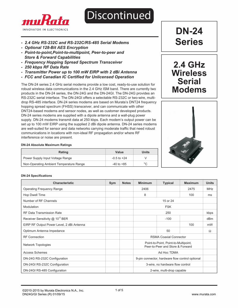
DN-24 series modems are supplied with a dipole antenna and a wall-plug power
supply. DN-24 modems transmit data at 250 kbps. Each modem’s output power can be
set up to 100 mW EIRP using the supplied 2 dBi dipole antenna. DN-24 series modems
are well-suited for sensor and data networks carrying moderate traffic that need robust
communications in locations with non-ideal RF propagation and/or where RF
interference or noise are present.
- 2.4 GHz RS-232C and RS-232C/RS-485 Serial Modems
- Optional 128-Bit AES Encryption
- Point-to-point,Point-to-multipoint, Peer-to-peer and
Store & Forward Capabilities
- Frequency Hopping Spread Spectrum Transceiver
- 250 kbps RF Data Rate
- Transmitter Power up to 100 mW EIRP with 2 dBi Antenna
- FCC and Canadian IC Certified for Unlicensed Operation
©2010-2015 by Murata Electronics N.A., Inc.DN24G/GI Series (R) 01/09/15
1 of 5www.murata.com
Characteristic Sym Notes Minimum Typical Maximum Units
Serial Port Baud Rates1.2, 2.4, 4.8, 9.6, 14.4, 19.2, 28.8,
38.4, 57.6, 115.2, 230.4, 250.0kbps
DC Power Supply Voltage Range VCC +9 +24 Vdc
Peak Transmit Mode Current, 100 mW EIRP 190 mA
Average Receive Mode Current:
Base, Continuous Data Stream 129 mA
Remote, Linked, No Data 34 mA
Remote, Continuous Data Stream 44 mA
Nominal Dimensions 3.3 x 3.2 x 1 inches (84.6 x 82.0 x 25.4 mm)
MountingLeft and Right Flanges, Two Pre-drilled Holes
in Each Flange
Operating Temperature Range -40 85oC
Operating Relative Humidity Range, Non-condensing 10 90 %
DN-24 Specifications
©2010-2015 by Murata Electronics N.A., Inc.DN24G/GI Series (R) 01/09/15
2 of 5www.murata.com
DN-24 Series Modem Operation
The DN-24 series 2.4 GHz modems provide a low
cost, ready-to-use solution for robust wireless
data communications in the 2.4 GHz ISM band. There
are currently two products in the DN-24 series, the
DN-24G and the DN-24GI. The DN-24G provides an
RS-232C serial interface with optional hardware flow
control. The DN-24GI offers a selectable RS-232C
three-wire interface or a two-wire, multi-drop RS-485
interface. DN-24 series modems are based on RFM’s
DNT24 frequency hopping spread spectrum (FHSS)
transceiver, and can communicate with other DNT24-
based modems and sensor nodes, as well as
customer developed products.
DN-24 series modems are supplied with a reverse
SMA dipole antenna and a universal wall-plug power
supply. DN-24 modems transmit data at 250 kbps.
The transmitter output power can be set up to 100 mW
EIRP using the supplied 2 dBi dipole antenna.
Optional high gain directional and omni-directional
antennas are available from Murata to extend operating range where allowed by local regulations.
DN-24 series modems are well-suited for sensor and
data networks carrying moderate traffic that need
robust communications in locations with non-ideal RF
propagation and/or where RF interference or noise are
present.
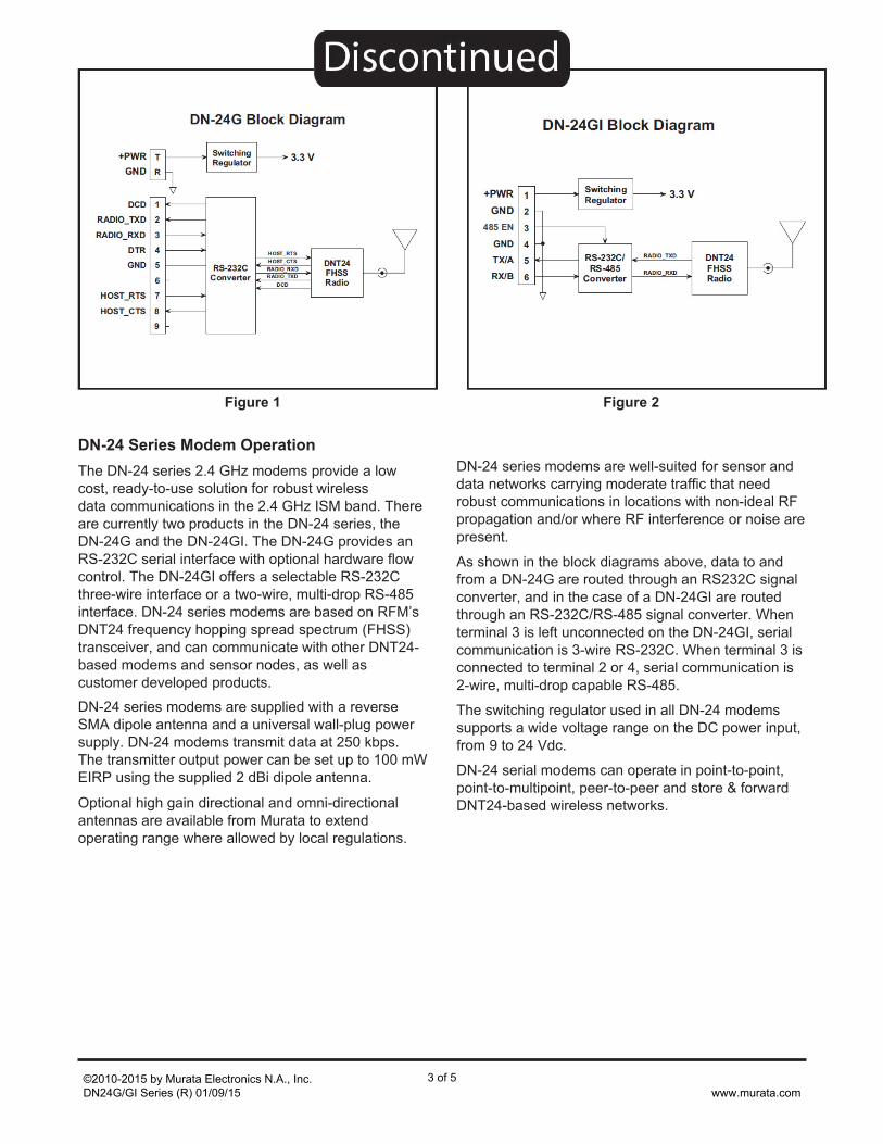
As shown in the block diagrams above, data to and
from a DN-24G are routed through an RS232C signal
converter, and in the case of a DN-24GI are routed
through an RS-232C/RS-485 signal converter. When
terminal 3 is left unconnected on the DN-24GI, serial
communication is 3-wire RS-232C. When terminal 3 is
connected to terminal 2 or 4, serial communication is
2-wire, multi-drop capable RS-485.
The switching regulator used in all DN-24 modems
supports a wide voltage range on the DC power input,
from 9 to 24 Vdc.
DN-24 serial modems can operate in point-to-point,
point-to-multipoint, peer-to-peer and store & forward
DNT24-based wireless networks.
� � � � � � �� � �
� � � � �� � � �� � � �
� � � � � � �� � � � � �
� � � � �
� �
! " # �
� � � � � � $ � � % � � � � � � &
'
�
�
�
(
)
� �
� * � + , - � . �
� * � + , - � . �
�
�
/
0
1
� � �
� , � � - � � �
� , � � - � � �
� � �� , � � - � � �
� , � � - � � �
� * � + , - � . �
� * � + , - � . �
� � �
Figure 1
� � � � � � � 2� � � � 0 (
� � �
� � � � �� � � �� � � �
� � � � � � �� � � � � �
� � � � �
� �
! " # �
� � � � � + � $ � � % � � � � � � &
'
�
�
�
(
)
� 0 ( � 3 �
� �
� . 2 *
� . 2 $
� * � + , - � . �
� * � + , - � . �
Figure 2
©2010-2015 by Murata Electronics N.A., Inc.DN24G/GI Series (R) 01/09/15
3 of 5www.murata.com
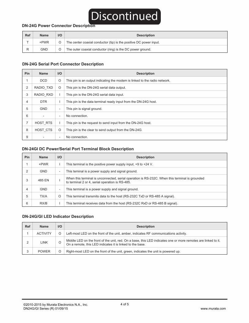
Pin Name I/O Description
1 +PWR I This terminal is the positive power supply input, +9 to +24 V.
2 GND - This teminal is a power supply and signal ground.
3 485 EN IWhen this terminal is unconnected, serial operation is RS-232C. When this terminal is groundedto terminal 2 or 4, serial operation is RS-485.
4 GND - This terminal is a power supply and signal ground.
5 TX/A O This terminal transmits data to the host (RS-232C TxD or RS-485 A signal).
6 RX/B I This terminal receives data from the host (RS-232C RxD or RS-485 B signal).
Ref Name I/O Description
1 ACTIVITY O Left-most LED on the front of the unit, amber, indicates RF communications activity.
2 LINK OMiddle LED on the front of the unit, red. On a base, this LED indicates one or more remotes are linked to it.On a remote, this LED indicates it is linked to the base.
3 POWER O Right-most LED on the front of the unit, green, indicates the unit is powered up.
DN-24GI DC Power/Serial Port Terminal Block Description
Pin Name I/O Description
1 DCD O This pin is an output indicating the modem is linked to the radio network.
2 RADIO_TXD O This pin is the DN-24G serial data output.
3 RADIO_RXD I This pin is the DN-24G serial data input.
4 DTR I This pin is the data terminal ready input from the DN-24G host.
5 GND - This pin is signal ground.
6 - - No connection.
7 HOST_RTS I This pin is the request to send input from the DN-24G host.
8 HOST_CTS O This pin is the clear to send output from the DN-24G.
9 - - No connection.
DN-24G/GI LED Indicator Description
DN-24G Power Connector Description
Ref Name I/O Description
T +PWR O The center coaxial conductor (tip) is the positive DC power input.
R GND O The outer coaxial conductor (ring) is the DC power ground.
DN-24G Serial Port Connector Description
©2010-2015 by Murata Electronics N.A., Inc.DN24G/GI Series (R) 01/09/15
4 of 5www.murata.com
� � 4 � 4 / ( � 5 ' � 1 ' 6� � " � � � � 7
' � 4 45 � ( � � 6
4 � � 4 45 ' 4 � ' ) 6
4 � ' ( 45 � � 0 ' 6
4 � ' ( 45 � � 0 ' 6
� � � � 45 0 � � ) � 6
� � � � 45 0 � � 4 4 6
� � � � (5 ) ' � 0 ( 6
� � ( � 45 ) � � � ) 6
� � � � � � , � � � � � � � � � �
4 � / 1 (5 � 4 � ' 1 6
� � & � 7 � 7 � 7 � � � � � � � � � 7 � � � � 5 & & 6
* � � + � + � 8
9 + � :
" , # 3 �
� 3 � + * 9
! 1 � � � �
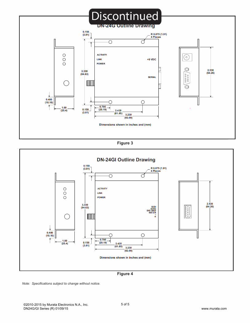
Figure 3
Note: Specifications subject to change without notice.
� � 4 � 4 / ( � 5 ' � 1 ' 6� � " � � � � 7
' � 4 45 � ( � � 6
4 � � 4 45 ' 4 � ' ) 6
4 � ' ( 45 � � 0 ' 6
4 � ' ( 45 � � 0 ' 6
� � � � 45 0 � � ) � 6
� � � � 45 0 � � 4 4 6
� � � � (5 ) ' � 0 ( 6
� � ( � 45 ) � � � ) 6
� � � � � + � , � � � � � � � � � �
4 � / 1 (5 � 4 � ' 1 6
� � & � 7 � 7 � 7 � � � � � � � � � 7 � � � � 5 & & 6
* � � + � + � 8
9 + � :
" , # 3 �
$ 2 � +* 2 � ,
� + � � �� 0 ( � 3 �
!�
Figure 4
©2010-2015 by Murata Electronics N.A., Inc.DN24G/GI Series (R) 01/09/15
5 of 5www.murata.com