dnn fr ld pltn - springer · n btnn d dpt th r f thnnt vr t lbl t th fft f brn, r nd rrn, nd fr th...
TRANSCRIPT

Designing for Gold Plating
INFLUENCE ON COST AND RELIAEILITY
Harold SilmanIndustrial Consultant, London
Good design plays an important part in ensuring that gold-platedproducts or components are produced efficiently and that they performsatisfactorily in service. The various design parameters that in-fluence the electrodeposition of gold and the quality of the platedfinish are discussed in detail and examples are given of the princi paldifficulties encountered by electroplaters and of how they can beeliminated, or at least appreciably reduced, by attention to design.
Design plays an important part in electroplating,not only in keeping down costs but in ensuring thatthe product wilt have a good appearance and performsatisfactorily in service. This is especially truc in thecase of gold plating, where the tost of the metal raakesit essential that the deposit should be as uniform aspossible so as to meet the minimum thicknessspecifications increasingly demanded without un--necessarily exceeding them at any point. It is desir-able that the designer should be conversant with thebasic principles of the processes to be employed, andtheir limitations, as well as with the conditions ofservice to which the plated articles are to be sub-jected, to ensure that plating can be carried outefficiently and economically. He should co--operarewith the electroplater at the design stage to avoiddifficulties which may subsequently prove costly toovercome, result in high reject rates, and yield anunsatisfactory product.
Finishing processes are not cheap to carry out,especially in the case of gold plating to specification.Good design enables good finishes to be applied, andsmalt changes can often be made which can helpenormously in simplifying production and in reduc--ing costs. On the other hand the designer should notallow himself to be submerged by fear of problemswhich his designs may create in production; muchprogress in finishing techniques has resulted fromthe challenge presented by "impossible" designs. Agood example of a complicated design, dictated byservice requirements, but one which successfullychallenged the ingenuity of the plater, is shown inFigure 1.
Gold plating is becoming increasingly importantfor industrial applications, and a wide variety ofprocesses is available, each having its advantages forparticular purposes. It is not proposed to discuss
them in detail, since the general considerations withrespect to design apply to a greater or lesser eitent toall of them.
Meehanical FinishingMost articles have to be given some kind of initial
mechanical finish, such as grinding or polishing,before they are plated. This is generally carried outby means of abrasives on suitable beits or wheels,either by hand or on automatic or semi-automaticmachines. For special purposes, a variety of blastingprocedures is available while, for the finishing ofarticles in bulk, barrel polishing or the newer vibra--tory finishing methods may be employed. In this wayall kinds of surface imperfections are removed and thearticles made ready for the plating process.
The following are some of the more importantaspects to consider in mechanical finishing:
(a)Abrupt changes in shape, sharp edges (whichcan damage wheels and beits), and blind holesor joint crevices (which can retain polishingcompound) are to be avoided.
(b) Large flat areas should be broken up in sameway so as to make theet less liable to scratchesand minor damage. It is also difficult to produceuniformly flat reflecting surfaces by polishing,while they are also susceptible to subsequentdamage.
(c)Projections and protuberances should beavoided since they are difficult to polisti andmay damage polishing buffs.
(d) Deep recesses and re-entrant areas should beavoided as far as possible, and all surfaces to bepolisled should be readily accessible to polish-ing wheels of normai diameter. Fine surfacepatterns are also undesirable, as they may belost or blurred in polishing.
38

Fig. 1 While good designenables electroplating to becarried out efciently andeconomicaily, complicated de-signs dictated by servicerequirements can sometimeslead to progress in platingtechniques. This U.H.F.resonant cavity from an air-home transponder, designedand made by Cossor Electro-nics, is Bast in a Bilicon.-aluminium alloy and machin.ed to a high finish on thesignificant surfaces. It is thenelectroplated ,with nickel,silver and finally gold. Inorder to achieve uniformity indeposit thickness in quantityproduction the electroplating,carried out hy Process Ser.vices, involved the use of threeinternat anodes and one ex.-ternal anode, all operating atdifferent currents and requir-ing complex circuitry toachieve the required result
(e) Articles intended for bulk polishang should besufficiently strong to withstand the tumblingaction, and should not stick together or inter-lock. A dimple or a raised edge is useful onflat surfaces to prevent them sticking together.
Design for RackingAll articles, except those to be plated in barrels,
have to be racked for transfer through the degreasing,cleaning, plating, rinsing and drying cycles, and musttherefore be suspended from suitable racks. First ofall it is necessary to establish the "significant surface",that is the part of the component which is essentialto its appearance or serviceability. It must then bedesigned in such a way that it can be held securely onthe plating rack with good electrical contact, andwithout preventing the plating of any part of thesignificant surface. Sometimes the designer may haveto incorporate lugs to enable proper contact to bemade, these being removed after finishing. This,however, should rarely be needed.
Another important point is that provision must bemade for drainage from the racked part; hence it isnecessary that the designer should have an indicationas to how the articles are to be suspended from theracks so that provision can be made for drainageholes if possible. Trapping of solution is to beavoided, since it causes contamination by carry-over,as well as by changing the composition of solutionsand causing a wastage of chemicals. It can also leadto corrosion by the entrapment of residues and salts,Air entrapment must also be prevented, since this
can cause unplated areas to occur, white gas canaccumulate in such areas during cleaning andplating.
In the case of articles to be barrel plated, there arespecial requirements in addition to those stated abovefor plating on racks. The articles should be suffi-
+ - +
% \\/ , F •1 ,------- -
....
f \ r/
Fig. 2 A cathode consisting of a flat plate,positioned parallel to an anode in an electro-plating solution, should theoretically receive adeposit of uniform overall thiekness. In practice,however, there will he a concentration of currentflow at the edges, giving a greater thickness ofdeposit in these areas
39
0.028 cm 0030 cm
0'Ol
(c) angle)s0(external (d) RADIUS
angle) r22 cm
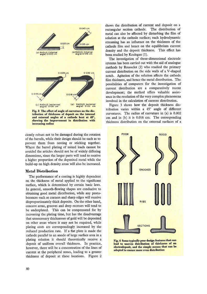
Fig. 3 The effect of angle of curvature on the dis-tribution of thiekness of deposit on the internaland external angles of a cathode bent at 45°,showing the improvement in distribution withincreasing radius
Fig. 4 Some typically poon design features that canlead to uneven distribution of thiekness of aneleetrodeposit, and the simple means that eau beadopted to ensure more even distribution
0.045 cm
Afr X025 cm ,O!C25 cm
(a) RADIUS [internat (b)RADIUS (intcrnafangle) 0-002 cm angle) 0 016 cm
shows the distribution of current and deposit on arectangular section cathode. The distribution ofmetal can also be affected by disturbing the film ofsolution at the cathode surface; such hydrodynamicstreanung has an influence on the thickness of thecathode film and hence on the equilibrium currentdensity and the deposit thickness. This effect haasbeen studied by Keulegan (1).
The investigation of three-dimensional electrodesystem.s has been carried out with the aid of analoguemethods by Rousselot (2) who studied the primarycurrent distribution on the side walls of a V-shapednotch. Agitation of the solution affects the cathodefilm thickness, and hence the metal distribution. Thepossibilities of computers for the investigation ofcurrent distribution are a comparatively recentdevelopment; the method offers valuable assist-ance in the resolution of the verg complex phenomenainvolved in the calculation of current distribution.
Figure 3 shows how the deposit thickness dis-tribution varies witpin a 45° angle of differentcurvatures. The radius of curvature in (a) is 0.002cm and in (b) it is 0.016 cm. The correspondingthickness distribution on the external surfaces of a
ciently robust not to be damaged during the rotationof the barrels, while their design should be such as toprevent them from nesting or sticking together.Where the barrel plating of mixed loads cannot beavoided the articles should not be of widely differingdimensions, since the larger parts will tend to receivea higher proportion of the deposited metal while thebuild-up on high density areas will also be increased.
Metal DistributionThe performance of a coating is highly dependent
on the thickness of metal applied to the significantsurface, which is determined by certain basic laws.In general, smooth-flowing slaapes are conducive toobtaining good metal distribution, while any protu-berances such as corners and sharp edges will receivedisproportionately thick deposits. On the other hand,concave areas, grooves and deep recesses will tend tobe underplated. This can be compensated for byincreasing the plating time, but pas the disadvantagethat unnecessary thicknesses of gold will be depositedon other areas where it may not be required, whileplating costs are correspondingly increased by thereduced production rate. If a flat plate is made thecathode parallel to an anode of large surface area in aplating solution it should theoretically receive adeposit of uniform overall thickness. In practice,however, there will be a concentration of the lines ofcurrent at the peripheral zones, leading to a greaterthickness of deposit at these locations. Figure 2
POOR GOOD
3ROOVES
R1 BSII Si
40
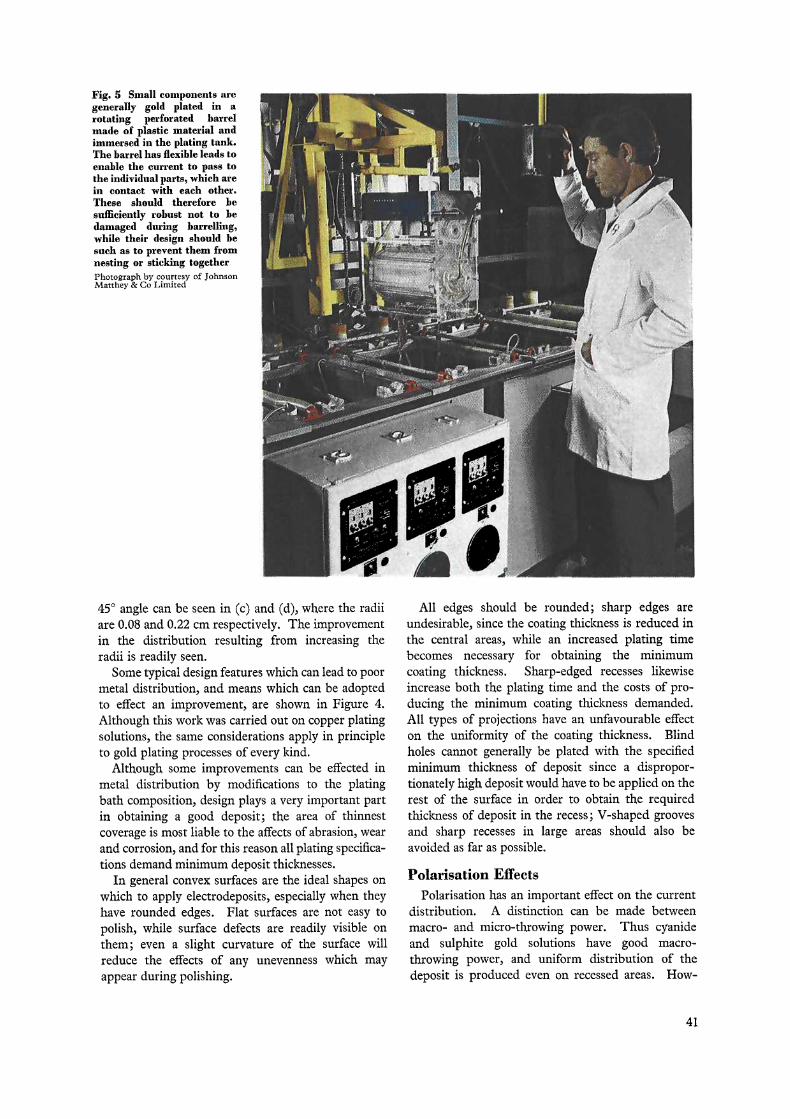
Fig. 5 Sinall components aregenerally gold plated in arotating perforated barrelmade of plastic material andimmersed in the plating tank.The barrel has flexible leads toenable the current to pass tothe individual parts, which arein contact with Bach other.These should therefore besufficiently rohust not to bedamaged during barrelling,while their design should hesuch as to prevent them fromnesting or sticking togetherPhotograph by courtesy of JohnsonMatthey & Co Limited
450 angle can be seen in (c) and (d), where the radiiare 0.08 and 0.22 cm respectively. The improvementin the distribution resulting from increasing theradii is readily seen.
Some typical design features which can lead to poormetal distribution, and means which can be adoptedto effect an improvement, are shown in Figure 4.Although this work was carried out on topper platingsolutions, the same considerations apply in principleto gold plating processes of every kind.
Although some improvements can be effected inmetal distribution by modifications to the platingbath composition, design plays a very important partin obtaining a good deposit; the area of thinnestcoverage is most liable to the affects of abrasion, wearand corrosion, and for this reason all plating specifica-tions demand minimum deposit thicknesses.
In general convex surfaces are the ideal shapes onwhich to apply electrodeposits, especially when theyhave rounded edges. Flat surfaces are not easy topolish, while surface defects are readily visible onthem; even a slight curvature of the surface willreduce the effects of any unevenness which mayappear during polishing.
All edges should be rounded; sharp edges areundesirable, since the coating thickness is reduced inthe tentral areas, while an increased plating timebecomes necessary for obtaining the minimumcoating thickness. Sharp-edged recesses likewiseincrease bath the plating time and the costs of pro-ducing the minimum coating thickness demanded.All types of projections have an unfavourable effecton the uniformity of the coating thickness. Blindholes cannot generally be plated with the specifiedminimum thickness of deposit since a dispropor--tionately high deposit would have to be applied on therest of the surface in order to obtain the requiredthickness of deposit in the recess; V-shaped groovesand sharp recesses in large areas should also beavoided as far as possible.
Polarisation Efects
Polarisation has an important effect on the currentdistribution. A distinction can be made betweenmacro- and micro-throwing power. Thus cyanideand sulphite gold solutions have good macro-throwing power, and uniform distribution of thedeposit is produced even on recessed areas. How-
41
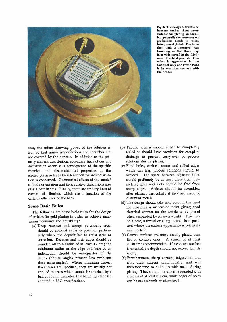
Fig. 6 The design of transistorheaders makes them moresuitable for plating on racks,hut generally the pressures onproduction resuit in theetheing barrel plated. The leadsthen tend to interfere withtumbling, so that there mayhe a wide spread in the thick-ness of gold deposited. Thiseffect is aggravated by thefact that only one of the leadsis in electrical contact withthe header
ever, the micro-throwing pover of the solution islow, so that minor imperfections and scratches arenot covered by the deposit. In addition to the pri-mary current distribution, secondary lines of currentdistribution occur as a consequence of the specificchemical and electrochemical properties of theelectrolyte in so far as their tendency towards polarisa-tion is concerned. Geometrical effects of the anode/cathode orientation and their relative dimensions alsoplay a part in this. Finally, there are tertiary lines ofcurrent distribution, which are a function of thecathode efficiency of the bath.
Some Basic RulesThe following are some basic rules for the design
of articles for gold plating in order to achieve max-imum economy and reliability :
(a) Deep recesses and abrupt re-entrant areasshould be avoided as far as possible, particu-larly where the deposit has to resist wear orcorrosion. Recesses and their edges should berounded off to a radius of at least 0.2 cm ; theminimum radius at the edge and base of anindentation should be one-quarter of thedepth (obtuse angles present less problemsthan acute angles). Where minimum depositthicknesses are specified, they are usually notapplied to areas which cannot be touched by abals of 20 mm diameter, this being the standardadopted in I S O specifications.
(b) Tubular articles should either be completelysealed or should have provision for completedrainage to prevent carry-over of processsolutions during plating.
(c)Blind holes, cavities, seams and rolled edgeswhich can trap process solutions should beavoided. The space between adjacent holesshould preferably be at least twice their dia-meters; holes and slots should be free fromsharp edges. Articles should be assembledafter plating, particularly if they are made ofdissimilar metals.
(d) The design should take into account the needfor providing a suspension point giving goodelectrical contact on the article to be platedwhen suspended by its own weiglit. This maybe a hole, a thread or a lug located in a posi-tion witere the surface appearance is relativelyunimportant.
(e) Convex surfaces are more readily plated thanflat or concave ones. A crown of at least0.040 cm is recommended. If a concave surfaceis essentaal, its depth should not exceed half itswidth.
(f) Protuberances, sharp corners, edges, fins andribs, draw current preferentially, and willtherefore tend to build up witti, metal duringplating. They should therefore be rounded witha radius of at least 0.1 cm, while edges of holescan be countersunk or chamfered.
42

(g) The electroplating of screw threads presentsspecial problems. The distribution tends to benon-uniform, which can result in assemblydifficulties.
The table shows the minimum radii which havebeen recommended by Safranek and Underwoodfor angles in recesses in order to obtain satisfactoryelectroplating (3).
Minimum Radii at Angles in Recesses
Minimum Radius of the AngleDepth of Recess between Opposite Surfaces
(mm) (mm)
1.6 0.43.2 0.86.4 1.69.6 2.4
12.8 3.2
In accordance with ISO specifications, the mini-mum coating thickness specifications apply, however,only to surfaces which can be touched by a bals of20 mm diameter.
PLATING RACK
ANODE C II ±ANODE
AUXILIAANODE
ANODE 11 AN ODE
BIPOLARELECTRODE
Fig. 7 In the plating of recessed orconcave surfaces it may be necessary touse either auxiliary anodes or, in somecases, Li-polar electrodes of an inertmetal, to assist in leading the currentto where deposition is needed
The design of die-cast components for goodplating requires that careful attention should begiven to the essential features of the die itself. Theparting of the die should not occur on flat surfaces,but at edges or raised areas. The same applies togates and air vents, as welf as to blind holes. Itshould be possible to remave casting sprues and boresby grinding without penetrating the skin of thecasting. Recessed flat areas should be avoided, and auniform wall thickness of 0.8 to 3 mm should beaimed for. There is nowadays a trend towardscastings with thinner walls, with a view to reducingweight and cast. Sharp cross-sectional changes in thecasting are also undesirable, since they interfere withmetal flow; this factor is improved by the rounding ofcorners and edges.
It is frequently necessary to cast inserts into zincdie-cast articles either to strengthen them or to - pro-vide attachments such as bushes or screw threads.Projecting threads tend to build up in metal whenplated, and this must be allowed for in specifying thetolerances of the plated article. The casting-in ofmetals such as steel or brass can also result in cleaningproblems since the cleaning procedures for thesemetals may differ from Chose for zint die-castings.This difficulty can be obviated by zinc plating insertsbefore casting-in so that the entire article to beplated can in effect be treated as made wholly of zinc.
Metal also tends to build up around the edges ofholes in die-castings. This effect can be reduced bymaking the bores slightly tapering. In general, it canbe said that designs that are suitable for die-castingare also favourable to good electroplating.
Auxiliary AnodesWhere recessed or concave surfaces have to be
plated it may be necessary to employ auxiliary anodes.Such anodes present problems in attachment, andthey slow, down production, so that their use is to beavoided if at all possible. Gold rads or wires aregenerally employed, with topper or nickel for appro-priate underc'óat deposits where these are required.
Bipolar electrodes are also useful in some cases.These are simply bars or strip of an inert metal whichserve the purpose of leading the current to where itis wanted. Bipolar electrodes are not connectedelectrically toleither the anode or the cathode. Theuse of both auxiliary and bipolar electrodes isillustrated diagrammatically in Figure 7.
Plating Articles in BulkArticles for barrel plating should be sufficiently
strong not to be damaged by impact during rotationof the barrel. Flat parts are liable to nest together, butthis tendency can be reduced by the introduction ofdesign features such as ridges or smalt projecting
43

5
Fig. 8 The variation in thickness of gold deposit on abarrel plated phosphor bronze spring contact
Point A B C D E F G H 1 J K
Thickness(internal) m 10 8 8 10 7 12 7 10 8 11 11
Thickness(externai) µm 10 9 7 8 8 9 8 8 7 9 11
areas. Mixed loads should also be avoided, as differentarticles will become plated with different thicknessesof deposit; larger articles, in particular, generallyreceive greater thicknesses.
Deposit thickness distribution in barrel plating isa special case. Generally the coating thicknessvariation tends to increase as the deposit thicknessincreases. Figure 8 shows the metal distribution on atypical barrel plated spring contact. For a properassessment of the mean thickness of the deposit onarticles in a barrel load, the testing of at least 15samples may be necessary, white 20 to 25 articles maywell be required for the calculation of the standarddeviation.
An important factor in thickness distribution is asmooth, rolling movement during the plating opera-tion. Complicated shapes cause a shielding effectand large thickness variations, especially when theplating times are short (4). The form of the internalsurface of the barrel, the rate of rotation, and thedepth of the bad are also significant.
Benefits from Good DesignThe question of design for gold plating industrial
products has been somewhat neglected when corn--pared with the amount of attention which has beenBiven to designing articles intended for plating withbase metals. Even in the Zatter case, however, muchmore could be done. Yet the benefits wliich canaccrue from proper attention to design metalsavings, the reduction of rejects, and economies ofproduction costs—generally are of outstanding im-portance in the case of gold plating.
The adoption of some of the measures which havebeen outlined will certainly involve some trouble, andpossibly a little expense, but these will be vastlyexceeded by the resulting gains.
References
1 G. H. Keulegan, "Hydrodynamics of Cathode Films"y. Res. Nat. Bur. Stand., 1951 3 47, (3), 156-169
2 R. H. Rousselot, "Current Distribution over Three-Dimensional Electrodes", Trans. Inst. Metal Finish., 1964,42, 100--106
3 W. H. Safranek and A. A. Underwood, "Infuence ofDesign on Electroplating of Zinc Diecastings", AmericanZinc Institute, New York, 2nd Edn., 1966
4 A. W. Wailbank and D. N. Layton, "The Plating of ScrewThreads", Trans. Inst. Metal Finish., 1955, 32, 308-335
Gold Reflectors for LasersThe many applications of high-power-density
lasers have introduced more severe requirements foroptical reflectors. In particular there is now a need forreflective surfaces consisting of high purity metals freefrom even minute defects such as inclusions or voidswhich might lead to damage. The preparation of suchhigh quality optical surfaces by a newly developed typeof precision machining of an electrodeposited layer ofgold is being actively pursued at the Oak Ridge Plantin Tennessee, and a progress report from there byF. B. Waldrop, M. J. Bezik, W. E. Tewes and R. C.Waldrop gives some details of the procedures adopted(Applied Opties, 1975, 14, (8), 1783-1787).
The high quality machined surface is obtained byusing special machine tools and toot bits that are groundfrom single crystal diamond, the process being referredto as diamond turning. As yet only copper, silver, goldand aluminium are suitable for machining by thismethod, but a more refractory metal such as beryllium(to reduce weight) or molybdenum (to achieve a lowcoefficient of expansion) is desirable for the substrate.These metals are of course generally characterised by atenacious oxide film that militates against adhesion of
an electrodeposit. This disadvantage has been over-come by a preliminary vapour deposition process—ionplating—in which an initial very thin but adherentcoating of aluminium is produced, upon which aconventional electrodeposit can be applied. Thisprocess is carried out in an argon atmosphere under apressure of a few microns. The surface to be treated isfirst cleaned by sputtering with argon ions to removeany oxide film. Aluminium ions are then acceleratedtowards the substrate by the high voltage with suchvelocity that they penetrate the surface, so ensuringexcellent adhesion to the most refractory of metals.
Electrodeposition on to this preliminary coating canthen be carried out and good adhesion can be achieved,using standard processes. The most suitable electrolytehas been found to be the citrate-based acid cyanidebath, and deposits from this electrolyte showed no voidsunder the microscope, a purity of 99.98 per cent, and adensity equivalent to that of solid gold.
These gold surfaces, diamond turned to a mirrorfinish., gave reflectivities of approximately 99.3 per centat 10.6 [ m in the as-machined condition, an outstand-ing quality in terms of reflectivities.
44