dnp points list and implementation
TRANSCRIPT

January 10, 2022
© S&C Electric Company 2008-2022, all rights reserved Instruction Sheet 766-560
IntelliRupter® PulseCloser® Fault InterrupterOutdoor Distribution (15.5 kV, 27 kV, and 38 kV)
DNP Points List and Implementation
Table of Contents
Section Page Section Page
Introduction . . . . . . . . . . . . . . . . . . . . . . . . . . . . . . . . 1
Status Points . . . . . . . . . . . . . . . . . . . . . . . . . . . . . . . 2
Analog Input Points . . . . . . . . . . . . . . . . . . . . . . . . .14
Analog Output Points . . . . . . . . . . . . . . . . . . . . . . 20
Control Points . . . . . . . . . . . . . . . . . . . . . . . . . . . . . .21
Group 0 Objects . . . . . . . . . . . . . . . . . . . . . . . . . . . 28
DNP Implementation . . . . . . . . . . . . . . . . . . . . . . . 29
Introduction This instruction sheet provides Distributed Network Protocol (DNP) points and DNP implementation information for an S&C IntelliRupter PulseCloser Fault Interrupter applied in an S&C IntelliTeam® SG Automatic Restoration System.
This instruction sheet is used with IntelliRupterInstaller-7.5.x.exe. The “x” can indi-cate any number from 0 to 255. Other related software component version information is found on the Setup>General>Revisions screen.
The DNP master station should define an IntelliRupter fault interrupter with the following Status, Analog Input, Analog Output, and Control points:
Point Count
Status 164
Analog Input 76
Analog Output 5
Control 62
The available DNP points are listed in Tables 1 through 4 on pages 2 through 27 in the same order they are presented for selection on the Setup>Communication>Point Mapping screens. IntelliRupter fault interrupter status, analog input, and control points can be assigned to any SCADA DNP point index. Point descriptions begin with a code number used to find the detailed definition in this instruction sheet. Refer to the “Communication Setup” section of S&C Instruction Sheet 766-530, “S&C IntelliRupter® PulseCloser® Fault Interrupter: Setup Instructions.” The code number for each point description is listed in Instruction Sheet 766-563LD (this publication) and is not the SCADA point index.
For a specific SCADA system, typically all IntelliRupter fault interrupters operate with the same DNP point index configuration.
Unless otherwise noted, each point is on if the condition is logically true or active.
NOTICEThe source address in IntelliLink® Setup Software is now 65432 instead of 1 .

2 S&C Instruction Sheet 766-560
Status Points
Table 1. Status Points
Code # Name—Definition
1 Pole 1 Open—On when Pole 1 interrupter contact status is Open . Otherwise, off .
2 Pole 1 Closed—On when Pole 1 interrupter contact status is Closed . Otherwise, off .
3 Pole 2 Open—On when Pole 2 interrupter contact status is Open . Otherwise, off .
4 Pole 2 Closed—On when Pole 2 interrupter contact status is Closed . Otherwise, off .
5 Pole 3 Open—On when Pole 3 interrupter contact status is Open . Otherwise, off .
6 Pole 3 Closed—On when Pole 3 interrupter contact status is Closed . Otherwise, off .
7 IntelliRupter Fault Interrupter Open—All Poles—On when Pole 1, Pole 2, and Pole 3 interrupter contact status is Open . Otherwise, off .
8 IntelliRupter Fault Interrupter Closed—All Poles—On when Pole 1, Pole 2, and Pole 3 interrupter contact status is Closed . Otherwise, off .
9 Manual Lever Locked Open—On when interrupter OPEN/CLOSE/READY lever is in the Open position . Off when lever is moved back to the Ready or Closed position .
10 Manual Disconnect Open—On when disconnect on disconnect style models is in the Open position . Otherwise, off .
11 General Profile 1 Active—On when the General Profile 1 setting is in effect . Otherwise, off .
12 General Profile 2 Active—On when the General Profile 2 setting is in effect . Otherwise, off .
13 General Profile 3 Active—On when the General Profile 3 setting is in effect . Otherwise, off .
14 General Profile 4 Active—On when the General Profile 4 setting is in effect . Otherwise, off .
15 Closing Profile 1 Active—On when the Closing Profile 1 setting is in effect after a Close command is issued by SCADA, Wi-Fi, external lever, or automatic load restoration and the Time for Closing Profile to be Active timer has not expired .
16 Closing Profile 2 Active—On when the Closing Profile 2 setting is in effect after a Close command is issued by SCADA, Wi-Fi, external lever, or automatic load restoration and the Time for Closing Profile to be Active timer has not expired .
17 Hot Line Tag Profile Active—On when the Hot Line Tag Profile state is in effect . Otherwise, off .
18 Ground Trip Blocked—On when the Ground Trip feature is blocked . Off when the Ground Trip feature is enabled .
These IntelliRupter fault interrupter features have multiple status points:
Open or Close: 1–8 Hot Line Tag: 17, 22–24
IntelliTeam System Operation: 56–74 Lockout: 88–90
Sensitive Earth Fault: 75–78 Site Acceptance Test: 101–104
Overcurrent Trip: 34–39 Loop Restoration: 79–82
Netlist Information: 105–109 General Profile: 11–14
Closing Profile: 15, 16, 21 PulseFinding™ Fault Location Technique: 91–93
TABLE CONTINUED ▶

S&C Instruction Sheet 766-560 3
Status Points
Table 1. Status Points—Continued
Code # Name—Definition
19 Circuit Testing Blocked—On when the Circuit Testing feature is blocked or the Hot Line Tag state is applied . Off when the Circuit Testing feature is enabled and the Hot Line Tag state is removed .
20 Test on Backfeed Blocked—On when the Test on Backfeed feature is blocked . Off when the Test on Backfeed feature is enabled .
21 2nd Closing Profile Selected—On when the Second Closing Profile setting is selected . Off when the First Closing Profile setting is selected . Note that a selected closing profile is different from an active closing profile .
22 Hot Line Tag Active SCADA—On when the Hot Line Tag setting activated by a SCADA command is in effect . Off when the Hot Line Tag setting is removed .
23 Hot Line Tag Active IntelliLink—On when the Hot Line Tag setting activated by an IntelliLink software command is in effect . Off when the Hot Line Tag setting is removed .
24 Hot Line Tag Active Manual—On when the Hot Line Tag setting activated by a manual lever is in effect . Off when the Hot Line Tag setting is removed .
25 Remote Operation On—On when the Remote Operation setting is on . Off when the Remote Operation setting is off and only local control is permitted .
26 Battery System Low—On when a routine battery test indicates low battery voltage . Otherwise, off . Battery Voltage setpoints are located on the Diagnostics>Control Power screen .
27 Battery System Bad—On when routine battery system test indicates inadequate battery capacity; however, the IntelliRupter fault interrupter will operate normally when power is available from the integrated power module(s) . Otherwise, off . The battery voltage setpoints are located on the Diagnostics>Control Power screen .
28 Battery Charger Problem—On when a routine battery system test turns the charger off because of overvoltage . Off when the next routine test does not detect overvoltage .
29 Ac Control Power Present—On when there is output from the integrated power module(s) . Otherwise, off .
30 IntelliRupter Fault Interrupter Shut Down Because of Control Power Loss—On just before the IntelliRupter fault interrupter shuts down because of loss of line power and no battery power . Otherwise, off .
31 Trip on Loss of Control Energy—On when the IntelliRupter fault interrupter trips because of loss of control energy and there is no ac power . Off when the IntelliRupter fault interrupter closes or a command to close the IntelliRupter fault interrupter is received .
32 Source Loading Data Is Active—On when the real-time feeder loading logic is active and in use . This point does not indicate whether the control is using actual real-time feeder-loading data received from a DNP master or the Default Source Segment Loading setting . Otherwise, off .
33 Real-Time Load Data May Be Old or Abnormal—On when the received DNP analog output value is less than the real-time three-phase load as sensed by the switch . It is also set if the real-time feeder-loading data have not updated within the configured time interval . Off when new data are received and the analog value is equal to or greater than the local measured load . Otherwise, off .
34 Overcurrent Timing—On when any Overcurrent element is timing . Otherwise, off .
TABLE CONTINUED ▶

4 S&C Instruction Sheet 766-560
Table 1. Status Points—Continued
Code # Name—Definition
35 Overcurrent Current, Pole 1—On if this pole was timing and >20% of trip and a Phase-Overcurrent element has tripped for this pole or another pole . On if the Phase-Overcurrent element for this pole was timing prior to a Ground-Overcurrent or Negative-Sequence element trip . Off when Phase-Overcurrent elements were not timing prior to trip, the IntelliRupter PulseCloser Fault Interrupter closes, or a command to close the IntelliRupter fault interrupter is given .
36 Overcurrent Current, Pole 2—On if this pole was timing and >20% of trip and a Phase-Overcurrent element has tripped for this pole or another pole . On if the Phase-Overcurrent element for this pole was timing prior to a Ground-Overcurrent or Negative-Sequence element trip . Off when Phase-Overcurrent elements were not timing prior to trip, the IntelliRupter PulseCloser Fault Interrupter closes, or a command to close the IntelliRupter fault interrupter is given .
37 Overcurrent Current, Pole 3—On if this pole was timing and >20% of trip and a Phase-Overcurrent element has tripped for this pole or another pole . On if the Phase-Overcurrent element for this pole was timing prior to a Ground-Overcurrent or Negative-Sequence element trip . Off when Phase-Overcurrent elements were not timing prior to trip, the IntelliRupter PulseCloser Fault Interrupter closes, or a command to close the IntelliRupter fault interrupter is given .
38 Overcurrent Trip, Any Pole—On when any Overcurrent element on Pole 1, Pole 2, or Pole 3 has tripped . Off when the IntelliRupter fault interrupter closes or a command to close the IntelliRupter fault interrupter is given .
39 Tripped to Lockout—On when the IntelliRupter fault interrupter is in the Lockout state as the result of an event and the IntelliTeam system begins the reconfiguration process . Off when a Close command is received .
40 Voltage Timing—On when any Voltage element is timing . Otherwise, off .
41 Voltage Trip—On when a Voltage element trips . Off when a Close command is received .
42 Frequency Timing—On when any Frequency element is timing . Otherwise, off .
43 Frequency Trip—On when any Frequency element trips . Off when a Close command is received .
44 Sectionalizing Timing—On when any Sectionalizing element is timing . Otherwise, off .
45 Sectionalizing Trip—On when any Sectionalizing element trips . Off when a Close command is received .
46 IntelliRupter Fault Interrupter Alarm—On when any alarm is active . Turned off automatically when the problem that caused the alarm is resolved .
47 IntelliRupter Fault Interrupter Warning—On when any warning is active . Turned off automatically when the problem that caused the warning is resolved .
48 IntelliRupter Fault Interrupter Error—On when any error is active . Turned off by a user action to clear the error .
49 Good Source Voltage—Terminal X—On when the X-side terminal voltages equal or exceed the Source Voltage Indication setting for the active profile . Otherwise, off .
50 Good Source Voltage—Terminal Y—On when the Y-side terminal voltages equal or exceed the Source Voltage Indication setting for the active profile . Otherwise, off .
Status Points
TABLE CONTINUED ▶

S&C Instruction Sheet 766-560 5
Status Points
Table 1. Status Points—Continued
Code # Name—Definition
51 Wi-Fi Is Connected—On when a Wi-Fi connection to the IntelliRupter fault interrupter is established . Otherwise, off .
52 Wi-Fi Intrusion Alarm—On when the Wi-Fi module reports a replay attack or improper authentication . Turned off by the user with control point 21, Clear Wi-Fi Intrusion Alarm .
53 Testing—On when the IntelliRupter fault interrupter is circuit testing . Off when the IntelliRupter fault interrupter closes or a command to close the IntelliRupter fault interrupter is given .
54 Close Blocked by Synch. Check—On when the Close operation is blocked by the Synch. Check feature (i .e ., different voltage magnitude, phase angle, or frequency on each side of the IntelliRupter fault interrupter) . Off when a Close command is received .
55 Pulseclosing, Fault Detected—On when a fault is detected during the PulseClosing® Technology operation . Off when the IntelliRupter fault interrupter closes or a Close command is received .
56 IntelliTeam Prohibit Restoration Timer Exceeded—On when the Prohibit Restoration Timer expires for any team in which this IntelliRupter fault interrupter is a member . Countdown starts when a transfer process begins at the team, usually when a sectionalizing event occurs . Timers in adjacent teams may start simultaneously . Each team decrements its timer independently so teams can potentially enter the Prohibit Restoration state asynchronously . Off when local manual operations have been cleared, all local trouble indications are cleared, and the Prohibit Restoration state is not active locally .
57 IntelliTeam Prohibit Restoration Enabled—On when the IntelliRupter fault interrupter receives a Prohibit Restoration command locally or from SCADA . No switch on any team in which this IntelliRupter fault interrupter is a member is allowed to automatically close, preventing automatic load restoration . Off when the Prohibit Restoration feature receives a SCADA Latch-Off command .
58 Setup Data Revision—On when the configuration entries for any enabled team defined in the control are modified . It remains on until the Team Setup parameter on the Setup>Team screen has been toggled from Stopped mode back to Running mode for any team where the configuration entries have been changed . Otherwise, off .
59 IntelliTeam Automatic Transfer In Progress—On when any team defined in the IntelliRupter fault interrupter is actively performing an Automatic Transfer operation . Otherwise, off .
60 IntelliTeam Return To Normal In Progress—On when any team defined in the IntelliRupter fault interrupter is actively performing a Return-to-Normal operation . Otherwise, off .
61 IntelliTeam Fault Pole 1—On when the Phase-Overcurrent element on Pole 1 or any of the Negative Sequence, Ground, or Sensitive Earth Overcurrent elements exceed 50% of the trip time setting . Turned off by the IntelliTeam system .
62 IntelliTeam Fault Pole 2—On when the Phase-Overcurrent element on Pole 2 or any of the Negative Sequence, Ground, or Sensitive Earth Overcurrent elements exceed 50% of the trip time setting . Turned off by the IntelliTeam system .
63 IntelliTeam Fault Pole 3—On when the Phase-Overcurrent element on Pole 3 or any of the Negative Sequence, Ground, or Sensitive Earth Overcurrent elements exceed 50% of the trip time setting . Turned off by the IntelliTeam system .
TABLE CONTINUED ▶

6 S&C Instruction Sheet 766-560
Table 1. Status Points—Continued
Code # Name—Definition
64 IntelliTeam Team Member Not Transfer Ready—On when an IntelliRupter fault interrupter operation is not consistent with the expected team operation . A variety of manual operations will take the IntelliRupter fault interrupter out of the Ready state . Off when local manual operations and all local trouble indications have been cleared .
65 Not All IntelliTeam Teams Transfer Ready—On when any team in which this IntelliRupter fault interrupter is a member is not fully operational . This may be because of conditions of individual team members, team-wide conditions such as the isolation of a fault or during configuration or coordination problems, or when the IntelliTeam SG Restoration system is set to the Disabled state on the IntelliTeam SG>Team Summary screen . Off when all conditions that caused this status point to be set initially have been cleared .Unless otherwise prohibited, team member IntelliRupter fault interrupters will revert to standalone basic protection when the Not Transfer Ready state is active, whether because of local conditions or conditions at adjacent team members .
66 IntelliTeam Team 1 Transfer Ready—On when team 1 is in the Ready to Transfer state . Off when any member of team 7 is set to Manual Operation mode, has any trouble indication active, has the Prohibit Restoration state active, or when the line section represented by team 7 contains a fault .
67 IntelliTeam Team 2 Transfer Ready—On when team 2 is in the Ready to Transfer state . Off when any member of team 7 is set to Manual Operation mode, has any trouble indication active, has the Prohibit Restoration state active, or when the line section represented by team 7 contains a fault .
68 IntelliTeam Team 3 Transfer Ready—On when team 3 is in the Ready to Transfer state . Off when any member of team 7 is set to Manual Operation mode, has any trouble indication active, has the Prohibit Restoration state active, or when the line section represented by team 7 contains a fault .
69 IntelliTeam Team 4 Transfer Ready—On when team 4 is in the Ready to Transfer state . Off when any member of team 7 is set to Manual Operation mode, has any trouble indication active, has the Prohibit Restoration state active, or when the line section represented by team 7 contains a fault .
70 IntelliTeam Team 5 Transfer Ready—On when team 5 is in the Ready to Transfer state . Off when any member of team 7 is set to Manual Operation mode, has any trouble indication active, has the Prohibit Restoration state active, or when the line section represented by team 7 contains a fault .
71 IntelliTeam Team 6 Transfer Ready—On when team 6 is in the Ready to Transfer state . Off when any member of team 7 is set to Manual Operation mode, has any trouble indication active, has the Prohibit Restoration state active, or when the line section represented by team 7 contains a fault .
72 IntelliTeam Team 7 Transfer Ready—On when team 7 is in the Ready to Transfer state . Off when any member of team 7 is set to Manual Operation mode, has any trouble indication active, has the Prohibit Restoration state active, or when the line section represented by team 7 contains a fault .
73 IntelliTeam Team 8 Transfer Ready—On when team 8 is in the Ready to Transfer state . Off when any member of team 7 is set to Manual Operation mode, has any trouble indication active, has the Prohibit Restoration state active, or when the line section represented by team 7 contains a fault .
Status Points
TABLE CONTINUED ▶

S&C Instruction Sheet 766-560 7
Status Points
Table 1. Status Points—Continued
Code # Name—Definition
74 IntelliTeam Manual Operation Team Condition—On when any member of a team registers a manual Open or Close switch operation that puts that team in the not Ready state . Some manual operations will not cause this condition, such as closing a source switch on a previously faulted team to allow a Return To Normal operation when the Return To Normal state is Enabled . Turned off by using the Clear Manual Operation button on the IntelliTeam SG>Team Summary screen . Also turned off by issuing SCADA control point #23, IntelliTeam Clear Manual Operation .
75 Sensitive Earth Trip Blocked—On when the Sensitive Earth Trip feature is blocked . Off when the Sensitive Earth Trip feature is enabled .
76 Overcurrent Timing—Sensitive Earth Fault—On when the Sensitive Earth element is timing . Otherwise, off .
77 Overcurrent Trip—Sensitive Earth Fault—On when the Sensitive Earth element trips . Off when the IntelliRupter fault interrupter closes or a Close command is received .
78 Tripped to Lockout—Sensitive Earth Fault—On when the IntelliRupter fault interrupter locks out as the result of a Sensitive Earth Trip element and the IntelliTeam system begins the reconfiguration process . Off when a Close command is received .
79 Loop Restoration Enabled—On when the Loop Restoration system is enabled . Otherwise, off .
80 Loop Restoration Ready—On when the Loop Restoration system is in the Ready state . Otherwise, off .
81 Loop Restoration Timing—On when the loop restoration timer is running . Otherwise, off .
82 Loop Restoration Reconfigured—On when the Loop Restoration system closes a normally open device, a normally open device locks out after testing, a normally closed device opens and locks out, or a normally closed device trips, then closes, and is now serving load in the opposite direction . Otherwise, off . This point is reset when a manual Open or Close command is received .
83 Current Flowing In Direction 1—On when current flows in Direction 1, as configured for this IntelliRupter fault interrupter on the Setup>General screen . Otherwise, off .
84 Current Flowing In Direction 2—On when current flows in Direction 2, as configured for this IntelliRupter fault interrupter on the Setup>General screen . Otherwise, off .
85 Close Blocked Due to Pulseclosing Not Available—On when a closing operation is blocked because of a PulseClosing Technology operation not being available and the user setting for Conventional Close if PulseClosing Not Available is set to No . The switch can still be closed by issuing a command that does not use a PulseClosing Technology operation . Off when a successful Close operation is performed .
86 Current Restraint-Phase—On when the Phase-Current Restraint mode is in effect for single-phase tripping . Otherwise, off .
87 Current Restraint-Ground—On when the Ground-Current Restraint mode is in effect for single-phase tripping . Otherwise, off .
88 Lockout-Pole 1—On when Pole 1 is in the Lockout state . Otherwise, off .
89 Lockout-Pole 2—On when Pole 2 is in the Lockout state . Otherwise, off .
90 Lockout-Pole 3—On when Pole 3 is in the Lockout state . Otherwise, off .
TABLE CONTINUED ▶

8 S&C Instruction Sheet 766-560
Status Points
Table 1. Status Points—Continued
Code # Name—Definition
91 Pulse Detected Fault-Pole 1—On when a fault is detected during a test sequence or close attempt by a PulseClosing Technology operation on Pole 1 . This point is cleared by the next successful Close operation on Pole 1 .
92 Pulse Detected Fault-Pole 2—On when a fault is detected during a test sequence or close attempt by a PulseClosing Technology operation on Pole 2 . This point is cleared by the next successful Close operation on Pole 2 .
93 Pulse Detected Fault-Pole 3—On when a fault is detected during a test sequence or close attempt by a PulseClosing Technology operation on Pole 3 . This point is cleared by the next successful Close operation on Pole 3 .
94 Single-Phase Operation Blocked—On when a Single-Phase Operation function is blocked . Otherwise, off .
95 Ground Trip Block Lever Applied—On when the GROUND TRIP BLOCK lever is applied . Otherwise, off .
96 Battery Disconnected—On when the battery is disconnected or no battery is installed . Otherwise, off .
97 Battery Test In Progress—On when a battery test is performed . Otherwise, off .
98 GPS Not Active Time Source—On when the GPS feature is not the active time source . Otherwise, off .
99 Communication Test—Toggles the state each time a Communication Test (control point 41) command is received . The initial state on power up is off .
100 Wi-Fi Disabled by SCADA—On when a Wi-Fi Disable (control point 42) command is received . Off when an Wi-Fi Enable (control point 43) command is received . An Wi-Fi Enable/Disable (control point 45) command toggles Wi-Fi communication on and off; on when Wi-Fi is disabled and off when Wi-Fi is enabled . Otherwise, off .
101 Site Acceptance Test: Script Active—On when a SAT Script has been received and the SAT Manager issues a Start Test command . Otherwise, off .
102 Site Acceptance Test: Switch Closed—On when the SAT process sees a Closed switch status .
103 Site Acceptance Test: Switch Open—On when the SAT process sees an Open switch status .
104 Site Acceptance Test: Test Prohibited—On when the IntelliLink software screenset locally prohibits all SAT activity . All requests issued from the SAT Manager are ignored . Otherwise, off .
105 Netlist Missing Runners—On when the received runner count doesn’t match the expected runner count . The Rapid Self Healing feature is disabled as long as this is the case . Otherwise, off .
106 Netlist Settings Propagation—On when the local control is receiving Netlist records from either a download or through propagation . If this is a Netlist download, the status point remains on until all expected runners arrive with the new Netlist . Otherwise, off .
107 Netlist Settings Accepted—On when a new Netlist has been successfully validated . Off when a Netlist is being downloaded or propagated . Off if the user has changed any team settings so they are different from the screenset .
108 Netlist Propagation Enabled—On when the IntelliLink software screenset or SCADA enables Netlist propagation . Otherwise, off . (Starting with Revision 7 .1 .x, the Netlist Propagation mode is always in the Enabled state; therefore this status point is always on .)
109 IntelliTeam II Mode Active—On when IntelliTeam II software is in use . Otherwise, off .
TABLE CONTINUED ▶

S&C Instruction Sheet 766-560 9
Table 1. Status Points—Continued
Code # Name—Definition
110 IntelliTeam Overload Alarm—On when the Post Restoration Load Management system is operational, the substation feeder is supplying sections that it does not normally supply, and an overload condition has been present when sampled for 10 consecutive times, 10 seconds apart . The alarm is cleared the first time an overload condition is not present when sampled or when the feeder is no longer supplying the extra sections .
111 Close Blocked Due to Insufficient Energy—On when a Close operation is prevented because of insufficient storage capacitor energy .
112 Communication Enhanced Coordination Ready—On when a closed IntelliRupter fault interrupter is active on a General Profile configured for CEC in at least one direction and all source-side IntelliRupter fault interrupters are closed and active on the same General Profile as this IntelliRupter fault interrupter . Otherwise, off .
113 Communication Enhanced Coordination Shift for X Terminal—On when the IntelliRupter fault interrupter shifts to the slower curve for the X terminal . Otherwise, off .
114 Communication Enhanced Coordination Shift for Y Terminal—On when the IntelliRupter fault interrupter shifts to the slower curve for the Y terminal . Otherwise, off .
115 Ground Overcurrent Trip—On when the Ground Overcurrent element trips . Off when IntelliRupter fault interrupter closes or a Close command is received .
116 Negative Sequence Overcurrent Trip—On when the Negative Sequence Overcurrent element trips . Off when IntelliRupter fault interrupter closes or a Close command is received .
117 Definite Time Overcurrent Trip—On when any Definite Time Overcurrent element trips . Off when the IntelliRupter fault interrupter closes or a Close command is received .
118 IT Out of Normal Switch State—On when the switch state is not in the Normally Open or Normally Closed state for the IntelliTeam system . Off when the switch state is the Normally Open or Normally Closed switch state for the IntelliTeam system .
119 Overcurrent Fault Detected—On when the fault-detection circuitry detects a Line Fault condition the SCADA operator has not reset . For a normally closed switch, line fault conditions clear automatically when three-phase line voltage has been sensed, the switch is in the Closed position, and 45 minutes have elapsed . For a normally open or normally closed switch, to clear the fault click on the faceplate/screenset pre-assigned User Command button .Note: The Fault condition also clears if the conditions above are met and the Clear Latched Overcurrent Status (control point 46) command is sent .
120 PLI Open—On when the switch has been opened by the Phase-Loss Isolation (PLI) logic . Otherwise, off .
121 Loop Restoration Close Blocked–Underfrequency—On when a Loop Restoration close attempt is blocked because of low frequency detection . Off when the IntelliRupter fault interrupter closes, a Close command is received, or the Loop Restoration setting is enabled by a manual-lever operation or by a Wi-Fi or SCADA command .
122 Any Automatic Timer in Progress—On when any of these timers is active: Overcurrent Timing, Voltage Timing, Frequency Timing, Sectionalizing Timing, Loop Restoration Timing, IntelliTeam Transfer in Progress, IntelliTeam Return to Normal in Progress, Fault Cycling, Pulse Test, or a shutdown is in progress because the Open Under Loss of Control Energy setting is enabled .
Status Points
TABLE CONTINUED ▶

10 S&C Instruction Sheet 766-560
Status Points
Table 1. Status Points—Continued
Code # Name—Definition
123 Low Single-Phase Low Voltage Alert—On when voltage is below the Low Single-Phase Low Voltage Threshold setting for one second . Off when voltage is above the threshold . To avoid flooding the logs and creating excessive SCADA alerts when the voltage is hovering at the threshold level, the DNP point is not allowed more than one transition (on or off) per minute . The value is computed every second but the alert checks and reports once every 30 seconds . This is configured on the Voltage Trip screen .
124 Low Three-Phase Low Voltage Alert—On when voltage is below the Low Three-Phase Low Voltage Threshold setting for one second . Off when voltage is above the threshold . To avoid flooding the logs and creating excessive SCADA alerts when the voltage is hovering at the threshold level, the DNP point is not allowed more than one transition (on or off) per minute . The value is computed every second, but the alert checks and reports once every 30 seconds . This is configured on the Voltage Trip screen .
125 Phase Overcurrent Alert—On when the Phase Overcurrent Alert setting is selected in the active general protection profile and phase current, on any phase in either direction, is above the alert value . The value is computed every second, but the alert checks and reports once every 30 seconds . This is configured on the Initial Trip screen .
126 Ground Overcurrent Alert—On when the Ground Overcurrent Alert setting is checked in the active general protection profile and ground current in either direction is above the alert value . The value is computed every second, but the alert checks and reports once every 30 seconds . This is configured on the Initial Trip screen .
127 Ground Overcurrent Timing—On when the Ground Overcurrent element is timing . Otherwise, off .
128 Phase Pole 1 Overcurrent Timing—On when the Pole 1 Phase Overcurrent element is timing . Otherwise, off .
129 Phase Pole 2 Overcurrent Timing—On when the Pole 2 Phase Overcurrent element is timing . Otherwise, off .
130 Phase Pole 3 Overcurrent Timing—On when the Pole 3 Phase Overcurrent element is timing . Otherwise, off .
131 Phase Any Pole Overcurrent Timing—On when any Phase Overcurrent element is timing . Otherwise, off .
132 Phase Any Pole Overcurrent Tripped—On when any Phase Overcurrent element trips . Off when the IntelliRupter fault interrupter closes, a Close command is received, or control point 44 is received .
133 IntelliTeam SG Close Blocked–Underfrequency—On when IntelliTeam SG operation is prohibited because of low frequency detection . Off when IntelliTeam SG system operation is enabled by a Wi-Fi or SCADA command .
134 Open-Source Sectionalizing Blocked—On when the Open-Source Sectionalizing element is in the Blocked state . Off when the Open-Source Sectionalizing element is in the Enabled state . When enabled the Open-Source Sectionalizing element will only function if Open-Source Sectionalizing is configured in the active profile .
135 Comm System has Poor Quality—On when the Bad Health alarm is active on the Link Keep Alive Tests screen and/or the Diagnostic Communications Tests screen . Otherwise, off .
136 VS-SEF Alert X—On when the Voltage Supervised Sens Earth Disable Trip check box is checked and the Voltage Supervised Sens Earth logic has been satisfied for the X direction . The alert automatically resets when the logic is no longer satisfied .
TABLE CONTINUED ▶

S&C Instruction Sheet 766-560 11
Table 1. Status Points—Continued
Code # Name—Definition
137 VS-SEF Alert Y—On when the Voltage Supervised Sens Earth Disable Trip check box is checked and the Voltage Supervised Sens Earth logic has been satisfied for the Y direction . The alert automatically resets when the logic is no longer satisfied .
138 IntelliLink Intrusion—On when an IntelliLink software log in attempt failed three times . Then, all users are locked out for 1 .5 minutes . Otherwise, off .
139 IntelliLink Session Active—On when user is presently logged in to the control . Otherwise, off .
140 External Port Linked—On when the External Interface Assembly is detected and the handshake message with the control module is received at least every 30 seconds . Otherwise, off . This point only applies to the SDA-4540R2 control with the External Interface option running firmware versions 7 .1 .24 and later . This point is marked reserved and is not applicable to SDA-4540R3 control firmware .
141 Not all Team Xfer Ready for X sec—At least one of the active teams where the local control is a member is not in the Ready state for greater than the configured time . Otherwise, off .
142 Close Pending Sync Check—When the Sync Check Enabled mode set to the Yes option and the IntelliRupter fault interrupter is open, if a Close or Sync Check Close command is not achieved before the Wait Timer setpoint expires, the Close command is discarded and this point is set to on . This remains on until a subsequent Close command is issued .
143 PR Remotely Transmitted—On when the local device sends the Prohibit Restoration SCADA command to remote devices in the Remote Prohibit Restoration Transmit List table because of an active Hot Line Tag, Frequency Trip, or Manual Operation state, or when a Prohibit Restoration state is activated via a front panel, IntelliLink software screen, or SCADA command . The status point is cleared when the device receives a Clear Remote Prohibit Restoration Status command from SCADA . Status point = 0x1F00
144 Enable Restoration Remotely Transmitted—On when the local device sends the Clear Remote Prohibit Restoration Status command to remote devices in the Remote Prohibit Restoration Transmit List table . This event can be triggered by executing a Clear Remote Prohibit Restoration Status command via IntelliLink software or receiving an IT Clear PR to all Devices command from SCADA . The status point is cleared when the device receives the Clear Remote Enable Restoration Status control point . Status point = 0x1F01
145 Pickup and Lockout Direction X—On when any element has picked up and locked out for a fault in direction X . Off when all elements and lockout are reset .
146 Pickup and Lockout Direction Y—On when any element has picked up and locked out for a fault in direction Y . Off when all elements and lockout are reset .
147 Phasor Data Captured—This point is used by the IntelliTeam® FMS Feeder Management System . Map this point and configure the unsolicited response setting according to the IntelliTeam Feeder Management System setup instructions .
148 Leakage Current Check Error—On when one of the per pole Definite Time Delay element for Open Vacuum Bottle Leakage detection algorithm has been satisfied . Otherwise, off .
149 Transfer Trip Enabled—On when the Transfer Trip state is enabled to allow the local device to send an Initiate Transfer Trip command to all non-zero RTU addresses in the Remote Transfer Trip Transmit List table after an Open and Lockout state because of a Protection or Automatic Sectionalizing event .
Status Points
TABLE CONTINUED ▶

12 S&C Instruction Sheet 766-560
Status Points
Table 1. Status Points—Continued
Code # Name—Definition
150 Transfer Trip Prohibit Restoration Initiated—On when an Initiate Transfer Trip control point has been received and executed . Off when the Prohibit Restoration state is no longer active and the control will be allowed to close by an automatic or manual operation . Note: This status point only applies to devices not teamed with a DG source . When teamed with DG, this status point will not get activated, even if a Transfer Trip command is initiated and executed .
151 Remote Prohibit Restoration Enabled from Local—On when the Enable Remote Transmit from Local P.R. setting is enabled on the local device .
152 Remote Prohibit Restoration Enabled from SCADA—On when the Enable Remote Transmit from SCADA P.R. setting is enabled on the local device .
153 DG Reconnect Delay Terminated—On when the DG Reconnect Delay Timer is aborted because of an abnormal system condition . The Transfer Trip Prohibit Restoration (TTPR) state remains active on the device and reconnecting the DG source back on the grid must be performed manually .
154 External Interface Maintenance Mode Applied—On when the External Interface Maintenance Mode input is active . Otherwise, off . See the “User Commands” section in S&C Instruction Sheet 766-530 . This point only applies to the SDA-4540R2 control with the External Interface option running firmware versions 7 .1 .24 and later . This point is marked reserved and is not applicable to SDA-4540R3 control firmware .
155 External Interface Ground Trip Applied—On when the External Interface Ground Trip Block input is active . Otherwise, off . This point only applies to the SDA-4540R2 control with the External Interface running firmware versions 7 .1 .24 and later . This point is marked reserved and is not applicable to SDA-4540R3 control firmware .
156 Hot Line Tag External Trip—On when the Hot Line Tag mode activated by the External Interface Option command is active . Otherwise, off . This point only applies to the SDA-4540R2 control with the External Interface running firmware versions 7 .1 .24 and later . This point is marked reserved and is not applicable to SDA-4540R3 control firmware .
157 Reserved .
158 Reserved .
159 Reserved .
160 Reserved .
161 Reserved .
162 Reserved .
163 Reserved .
164 Reserved .
165 Reserved .
166 Reserved .
TABLE CONTINUED ▶

S&C Instruction Sheet 766-560 13
Status Points
Table 1. Status Points—Continued
Code # Name—Definition
167 Transfer Declined Excess Load—Applies to all active teams configured within a control . Active when a transfer attempt has been declined because of load within the team(s) to be restored that exceeds the present capacity of the alternate source . Otherwise, off if another reason for the declined transfer occurs at the same control, if the transfer stops because of Prohibit Restoration or other error condition at any team member of this team, if the transfer succeeds at any team member of this team, or 5 minutes passes at this control with no further transfer-declined conditions as a result of excessive loading .
168 Transfer Declined Segment Limit—Applies to all active teams configured within a control . Active when a transfer attempt has been declined because of the number of teams being requested for restoration exceeding the line-segment limit associated with the alternate source . Otherwise, off if another reason for the declined transfer occurs at the same control, if the transfer stops because of Prohibit Restoration or other error condition at any team member of this team, if the transfer succeeds at any team member of this team, or 5 minutes passes at this control with no further transfer-declined conditions as a result of line-segment limit .
169 System Voltage Unrecognized—Active when the local system voltage is not recognized as a supported system voltage . It remains active until the issue is resolved through correct configuration of the system voltage setting .
170 Xfer Trip PR Initiated (DG POI)—Active when the DG POI device has received a Transfer Trip message and has initiated Prohibit Restoration mode on the POI IntelliTeam system device . Otherwise, off when the DG POI device is in any other state .
171 NET: Missing Runners in Adjacent FeederNet—Active when a missing runner condition exists in any adjacent FeederNet in an IntelliTeam system . Otherwise, off if there are no missing runner conditions in any adjacent FeederNet in an IntelliTeam system .
172 Transfer Trip Sent—Active when a device sends a Remote Transfer Trip message via the Remote Transmit list after it has opened and locked out because of a Protection or Automatic Sectionalizing event . It is cleared when the device is closed and in the Ready state .
173 External Port Open Latched—On when the External Interface Open Latched input is active . Otherwise, off . This point only applies to the SDA-4540R2 control with the external interface running firmware versions 7 .5 .xx and later . This point is marked reserved and is not applicable to SDA-4540R3 control module .
174 External Port Trip Latched—On when the External Interface Trip Latched input is active . Otherwise, off . This point only applies to the SDA-4540R2 control with the external interface running firmware versions 7 .5 .xx and later . This point is marked reserved and is not applicable to SDA-4540R3 control module .

14 S&C Instruction Sheet 766-560
Table 2. Analog Input Points
Code # Name—Definition
1 Voltage, Pole 1X—Primary phase-to-ground or phase-to-phase (1X to 2X voltage depending on setup) measured on Pole 1 Terminal X . Each count equals one Vac RMS .
2 Voltage, Pole 2X—Primary phase-to-ground or phase-to-phase (2X to 3X voltage depending on setup) measured on Pole 2 Terminal X . Each count equals one Vac RMS .
3 Voltage, Pole 3X—Primary phase-to-ground or phase-to-phase (3X to 1X voltage depending on setup) measured on Pole 3 Terminal X . Each count equals one Vac RMS .
4
Voltage, Pole 1Y—Primary phase-to-ground or phase-to-phase (1Y to 2Y voltage depending on setup) measured on Pole 1 Terminal Y . Each count equals one Vac RMS .Note: Because the IntelliRupter fault interrupter voltage sensors are high-impedance sensing devices, they will indicate a presence of voltage on the Y side terminals when the optional disconnect is installed and open . The voltage reading is an artifact of leakage current resulting from parasitic capacitance . Therefore the readings can be quite variable from unit to unit and pole to pole . Humidity and other weather related conditions add to the variability at a given unit .
5 Voltage, Pole 2Y—Primary phase-to-ground or phase-to-phase (2Y to 3Y voltage depending on setup) measured on Pole 2 Terminal Y . Each count equals one Vac RMS .
6 Voltage, Pole 3Y—Primary phase-to-ground or phase-to-phase (3Y to 1Y voltage depending on setup) measured on Pole 3 Terminal Y . Each count equals one Vac RMS .
7 90% Voltage Reference Standard—A constant representing 90% of the full-scale value .
8 0% Voltage Reference Standard—A constant representing the zero value .
9 Battery Voltage—Nominally 12 Vdc . If ac power is available the value is updated only during battery testing . If ac power is not available the value is continuously updated . One count equals 0 .0293 Vdc .
10 Current, Pole 1—Single-phase true RMS current measured on Pole 1 . Each count equals one ampere .
11 Current, Pole 2—Single-phase true RMS current measured on Pole 2 . Each count equals one ampere .
12 Current, Pole 3—Single-phase true RMS current measured on Pole 3 . Each count equals one ampere .
13 Residual Current—Vector sum of the fundamental power frequency currents on Pole 1, Pole 2, and Pole 3 . Each count equals one ampere .
14
Fault Current, Pole 1 at Time of Trip—Current at time of trip for the last overcurrent or tandem protective element that tripped and opened this pole regardless of which phase caused the trip . Cleared when this pole is manually closed (by a local command, a SCADA command, or IntelliLink software command) or by issuing the Clear Trip Indicators command (control point 44) . Each count equals one ampere .
Analog Input Points
TABLE CONTINUED ▶

S&C Instruction Sheet 766-560 15
Analog Input Points
Table 2. Analog Input Points—Continued
Code # Name—Definition
15
Fault Current, Pole 2 at Time of Trip—Current at time of trip for the last overcurrent or tandem protective element that tripped and opened this pole regardless of which phase caused the trip . Cleared when this pole is manually closed (by a local command, a SCADA command, or IntelliLink software command) or by issuing the Clear Trip Indicators command (control point 44) . Each count equals one ampere .
16
Fault Current, Pole 3 at Time of Trip—Current at time of trip for the last overcurrent or tandem protective element that tripped and opened this pole regardless of which phase caused the trip . Cleared when this pole is manually closed (by a local command, a SCADA command, or IntelliLink software command) or by issuing the Clear Trip Indicators command (control point 44) . Each count equals one ampere .
17 kW, Pole 1—Single-phase kW on Pole 1 calculated using instantaneous voltage and current and the respective voltage-current phase angle . Each count equals one kW .
18 kW, Pole 2—Single-phase kW on Pole 2 calculated using instantaneous voltage and current and the respective voltage-current phase angle . Each count equals one kW .
19 kW, Pole 3—Single-phase kW on Pole 3 calculated using instantaneous voltage and current and the respective voltage-current phase angle . Each count equals one kW .
20 Total kW—Sum of kW Pole 1, kW Pole 2, and kW Pole 3 . Each count equals one kW .
21 kvar, Pole 1—Single-phase kvar on Pole 1 calculated using apparent power, true power, and phase angle . Each count equals one kvar .
22 kvar, Pole 2—Single-phase kvar on Pole 2 calculated using apparent power, true power, and phase angle . Each count equals one kvar .
23 kvar, Pole 3—Single-phase kvar on Pole 3 calculated using apparent power, true power, and phase angle . Each count equals one kvar .
24 Total kvar—Sum of kvar Pole 1, kvar Pole 2, and kvar Pole 3 . Each count equals one kvar .
25
Power Factor, Pole 1—Single-phase power factor measured on Pole 1 reported as the cosine of the phase angle . Each count equals 0 .001 . For lagging angles, the power factor is reported as 0 to 2000 corresponding to angles from 180 to 0 . For leading angles, the power factor is reported as 2000 to 0 corresponding to angles from -180 to 0 .
26
Power Factor, Pole 2—Single-phase power factor measured on Pole 2 reported as the cosine of the phase angle . Each count equals 0 .001 . For lagging angles, the power factor is reported as 0 to 2000 corresponding to angles from 180 to 0 . For leading angles, the power factor is reported as 2000 to 0 corresponding to angles from -180 to 0 .
27
Power Factor, Pole 3—Single-phase power factor measured on Pole 3 reported as the cosine of the phase angle . Each count equals 0 .001 . For lagging angles, the power factor is reported as 0 to 2000 corresponding to angles from 180 to 0 . For leading angles, the power factor is reported as 2000 to 0 corresponding to angles from -180 to 0 .
28 Power Factor Angle of Pole 1—Angle cosine that is the power factor . Each count equals one-eighth of a degree .
TABLE CONTINUED ▶

16 S&C Instruction Sheet 766-560
Analog Input Points
Table 2. Analog Input Points—Continued
Code # Name—Definition
29 Power Factor Angle of Pole 2—Angle cosine that is the power factor . Each count equals one-eighth of a degree .
30 Power Factor Angle of Pole 3—Angle cosine that is the power factor . Each count equals one-eighth of a degree .
31 Total Harmonic Distortion—Pole 1, X Side Voltage—Each count equals 0 .1% .
32 Total Harmonic Distortion—Pole 2, X Side Voltage—Each count equals 0 .1% .
33 Total Harmonic Distortion—Pole 3, X Side Voltage—Each count equals 0 .1% .
34 Total Harmonic Distortion—Pole 1, Y Side Voltage—Each count equals 0 .1% .
35 Total Harmonic Distortion—Pole 2, Y Side Voltage—Each count equals 0 .1% .
36 Total Harmonic Distortion—Pole 3, Y Side Voltage—Each count equals 0 .1% .
37 Total Harmonic Distortion—Pole 1, Current—Each count equals 0 .1% .
38 Total Harmonic Distortion—Pole 2, Current—Each count equals 0 .1% .
39 Total Harmonic Distortion—Pole 3, Current—Each count equals 0 .1% .
40 Line Frequency—Each count equals 0 .01 Hz .
41 Temperature—The most recent temperature reading . Each count equals one degree Fahrenheit .
42 Number of Pole 1 Opening Operations—Number of interrupter operations on Pole 1 incremented on each Open operation .
43 Number of Pole 2 Opening Operations—Number of interrupter operations on Pole 2 incremented on each Open operation .
44 Number of Pole 3 Opening Operations—Number of interrupter operations on Pole 3 incremented on each Open operation .
45 Number of Pole 1 Closing Operations—Number of interrupter operations on Pole 1 incremented on each Close operation .
46 Number of Pole 2 Closing Operations—Number of interrupter operations on Pole 2 incremented on each Close operation .
47 Number of Pole 3 Closing Operations—Number of interrupter operations on Pole 3 incremented on each Close operation .
48 Number of Pole 1 Pulse Operations—Number of interrupter operations on Pole 1 incremented on each operation using PulseClosing Technology .
49 Number of Pole 2 Pulse Operations—Number of interrupter operations on Pole 2 incremented on each operation using PulseClosing Technology .
50 Number of Pole 3 Pulse Operations—Number of interrupter operations on Pole 3 incremented on each operation using PulseClosing Technology .
TABLE CONTINUED ▶

S&C Instruction Sheet 766-560 17
Table 2. Analog Input Points—Continued
Code # Name—Definition
51 Phase Angle, X Side Voltage to Y Side Voltage, Pole 1—Phase angle in degrees between the X side and Y side voltage signals . A positive value indicates that the X side is leading . Each count equals one-eighth degree .
52 Phase Angle, X Side Voltage to Y Side Voltage, Pole 2—Phase angle in degrees between the X side and Y side voltage signals . A positive value indicates that the X side is leading . Each count equals one-eighth degree .
53 Phase Angle, X Side Voltage to Y Side Voltage, Pole 3—Phase angle in degrees between the X side and Y side voltage signals . A positive value indicates that the X side is leading . Each count equals one-eighth degree .
54 Analog Communication Test—Displays the value sent to analog output point 5 . The initial state at powerup is zero .
55 Total kVA—Sum of kVA Pole 1, kVA Pole 2, and kVA Pole 3 . Each count equals one kVA .
56 Total Power Factor—Sum of kW Pole 1, kW Pole 2, and kW Pole 3 divided by the sum of kVA Pole 1, kVA Pole 2, and kVA Pole 3, reported as the cosine of the phase angle . Each count equals 0 .001 . For a balanced system with lagging angles, the power factor is reported as 0 to 2000 corresponding to angles from 180 to 0 (kvar always positive but kW goes from positive to negative) . For a balanced system with leading angles, the power factor is reported as 2000 to 0 corresponding to angles -180 to 0 (kvar always negative but kW goes from positive to negative) .
57 Latched Overcurrent, Pole 1—Current at time of trip for the last overcurrent or tandem protective element that tripped and opened this pole, including a Sectionalizing trip, regardless of which phase caused the trip . Cleared when this pole is manually Closed (by a local command, a SCADA command, or IntelliLink software command) or by issuing a Clear Trip Indicators (control point 44) command . Each count equals one ampere .
58 Latched Overcurrent, Pole 2—Current at time of trip for the last overcurrent or tandem protective element that tripped and opened this pole, including a Sectionalizing trip, regardless of which phase caused the trip . Cleared when this pole is manually Closed (by a local command, a SCADA command, or IntelliLink software command) or by issuing a Clear Trip Indicators (control point 44) command . Each count equals one ampere .
59 Latched Overcurrent, Pole 3—Current at time of trip for the last overcurrent or tandem protective element that tripped and opened this pole, including a Sectionalizing trip, regardless of which phase caused the trip . Cleared when this pole is manually Closed (by a local command, a SCADA command, or IntelliLink software command) or by issuing a Clear Trip Indicators (control point 44) command . Each count equals one ampere .
60 Delta Frequency—The difference in frequency between the X and Y sides . Reports X frequency minus Y frequency . Therefore a positive value indicates higher frequency on the X side and a negative value indicates higher frequency on the Y side . Each count equals 0 .01 Hz .
Analog Input Points
TABLE CONTINUED ▶

18 S&C Instruction Sheet 766-560
Table 2. Analog Input Points—Continued
Code # Name—Definition
61 Averaged Current, Pole 1—Single-phase time-averaged current measured on Pole 1 . 30 samples are averaged for the last 15 minutes and each count equals one ampere .When the Open-Source Sectionalizing element is set to the Yes setting, IntelliTeam SG or Loops Only, the current average will latch when the IntelliRupter fault interrupter is closed and the voltage has dropped below the Open Source Voltage Threshold setpoint . It will remain latched while the Open-Source Sectionalizing element is timing . If the Open-Source Sectionalizing element trips it will remain latched until the trip indication is cleared by closing the IntelliRupter fault interrupter or control point 44 is received . When the latch is cleared the average current will resume averaging from the latched value . Otherwise the current average will update normally .When the Open-Source Sectionalizing element is set to the No setting, samples will be collected when the IntelliRupter fault interrupter is open or closed . This value updates each time a new sample is processed and will never be latched .
62 Averaged Current, Pole 2—Single-phase time-averaged current measured on Pole 2 . Same as Analog Input Point 61 .
63 Averaged Current, Pole 3—Single-phase time-averaged current measured on Pole 3 . Same as Analog Input Point 61 .
64 Averaged Residual Current—Vector sum of the fundamental power-frequency current on Poles 1, 2, and 3 . 30 samples are averaged for the last 15 minutes and each count equals one ampere .When the Open-Source Sectionalizing feature is set to the Yes, IntelliTeam SG or Loops Only setting, the current average will latch when the IntelliRupter fault interrupter is closed and the voltage has dropped below the Open Source Voltage Threshold setting . It will remain latched while the Open-Source Sectionalizing element is timing . If the Open-Source Sectionalizing element trips it will remain latched until the trip indication is cleared by closing the IntelliRupter fault interrupter or control point 44 is received . When the latch is cleared, the average current will resume averaging from the latched value . Otherwise the current average will be updating .When the Open-Source Sectionalizing feature is set to the No setting, samples will be collected when the IntelliRupter fault interrupter is open or closed . This value will update each time a new sample is processed and will not be latched .
65 Fault Current Ground Time of Trip—This is the ground current at time of trip for the last ground overcurrent or tandem protective element that tripped . Cleared when the tripped pole or poles are manually closed (locally, via SCADA or IntelliLink software) or by issuing a Clear Trip Indicators (Control Point 44) command . Each count equals one ampere .
66 Leakage Current Time Pole 1—This shows the accumulated time for the Pole 1 Definite Time Delay element for the Open Vacuum Bottle Leakage detection algorithm .
67 Leakage Current Time Pole 2—This shows the accumulated time for the Pole 2 Definite Time Delay element for the Open Vacuum Bottle Leakage detection algorithm .
68 Leakage Current Time Pole 3—This shows the accumulated time for the Pole 3 Definite Time Delay element for the Open Vacuum Bottle Leakage detection algorithm .
Analog Input Points
TABLE CONTINUED ▶

S&C Instruction Sheet 766-560 19
Analog Input Points
Table 2. Analog Input Points—Continued
Code # Name—Definition
69D1 Phase Trip Level— When in use, the Low Cutoff value is displayed for the Direction 1 Phase Overcurrent element of the protection profile in use . Otherwise the Min. Trip value is displayed . One count equals one ampere . Zero (0) means the element is disabled or not applicable to the profile in use .①②
70D2 Phase Trip Level— When in use, the Low Cutoff value is displayed for the Direction 2 Phase Overcurrent element of the protection profile in use . Otherwise the Min. Trip value is displayed . One count equals one ampere . Zero (0) means the element is disabled or not applicable to the profile in use .②③
71
D1 Ground Trip Level— When in use, the Low Cutoff value is displayed for the Direction 1 Ground Overcurrent element of the protection profile in use . Otherwise the Min. Trip value is displayed . One count equals one ampere . Zero (0) means the element is disabled or not applicable to the profile in use . ①③
72D2 Ground Trip Level— When in use, the Low Cutoff value is displayed for the Direction 2 Ground Overcurrent element of the protection profile in use . Otherwise the Min. Trip value is displayed . One count equals one ampere . Zero (0) means the element is disabled or not applicable to the profile in use .②③
73
D1 Neg Seq Trip Level— When in use, the Low Cutoff value is displayed for the Direction 1 Negative Sequence Overcurrent element of the protection profile in use . Otherwise the Min. Trip value is displayed . One count equals one ampere . Zero (0) means the element is disabled or not applicable to the profile in use .①③
74
D2 Neg Seq Trip Level— When in use, the Low Cutoff value is displayed for the Direction 2 Negative Sequence Overcurrent element of the protection profile in use . Otherwise the Min. Trip value is displayed . One count equals one ampere . Zero (0) means the element is disabled or not applicable to the profile in use .②③
75D1 SEF Trip Level— When in use, the Low Cutoff value is displayed for the Direction 1 SEF Overcurrent element of the protection profile in use . Otherwise the Min. Trip value is displayed . One count equals one ampere . Zero (0) means the element is disabled or not applicable to the profile in use .①③
76D2 SEF Trip Level—When in use, the Low Cutoff value is displayed for the Direction 2 SEF Overcurrent element of the protection profile in use . Otherwise the Min. Trip value is displayed . One count equals one ampere . Zero (0) means the element is disabled or not applicable to the profile in use .②③
77 Reserved .
① D1 = Direction 1 .
② This point is only applicable to SDA-4540R2 controls with firmware version 7 .4 .xx and later and SDA-4540R3 controls with firmware version 7 .3 .xx and later .
③ D2 = Direction 2 .

20 S&C Instruction Sheet 766-560
Table 3. Analog Output Points
Code # Name—Definition
1 Application Layer Confirmation Retry Time—Time (100 to 65535 ms .) the IntelliRupter fault interrupter will wait for an application layer confirmation to an event response message before resending the request for confirmation .①
2 Application Layer Confirmation Retry Count—Number of times (0 to 10) the IntelliRupter fault interrupter will send an event response message if a confirmation is not received .
3 Control Point Select Time—During a select-before-operate procedure the time (10 to 1000 tenths of a second) allowed to elapse between receiving the select function for a point and receiving the operate function for it . If an operate function is not received within this period, the point is un-selected; another select function is required before the point will operate .
4 Real-Time Feeder Loading—Total averaged three-phase feeder loading (in amperes) measured at the source breaker . This value is used to determine if the load can be transferred to another source . Each count equals one ampere .
5 Analog Communication Test—Accepts a value that reports back through analog input point 54 .
Analog Output Points
① Set and read the Application Layer Confirmation Retry Time setpoint based on the required range:
Application Layer Confirmation Retry Time Range
Set Analog Output Value Read Analog Output Value②
100 to 32,737 ms . Group 41 variation 2 (16-bit) Group 40 variation 2 (16-bit with flag)
32,738 to 65,535 ms . Group 41 variation 1 (32-bit) Group 40 variation 1 (32-bit with flag)
② Class 0 will always report group 40 variation 2 and will report negative value for 32-bit values . Use group 40 variation 1 to read values between 32,738 to 65,535 ms .

S&C Instruction Sheet 766-560 21
Control Points
Table 4. Control Points
Code # Name—Definition
1 Open IntelliRupter Fault Interrupter—SCADA—This command opens all closed poles .
2 Close IntelliRupter Fault Interrupter—SCADA—This command closes all open poles .
3 General Profile 1—SCADA—Enables General Profile 1 .
4 General Profile 2—SCADA—Enables General Profile 2 . When Latch-Off, Breaker-Off, or Pulse-Off of Profile 2 occurs, the active profile will be returned to General Profile 1 .
5 General Profile 3—SCADA—Enables General Profile 3 . When Latch-Off, Breaker-Off, or Pulse-Off of Profile 3 occurs, the active profile will be returned to General Profile 1 .
6 General Profile 4—SCADA—Enables General Profile 4 . When Latch-Off, Breaker-Off, or Pulse-Off of Profile 4 occurs, the active profile will be returned to General Profile 1 .
7 Enable/Disable Hot Line Tag—SCADA—Enables or disables the Hot Line Tag profile .
8 Reserved .
9 Start Battery Test—SCADA—Begins a battery test cycle . If ac power is available, the battery charger is disconnected for several minutes during the test . If ac power is not available, a brief impedance test is used to evaluate the battery condition .
10 Clear Errors—SCADA—Clears all error flags . Alarms and warnings are not affected .
11 Enable/Block Ground Trip—Enables or blocks the Ground Trip feature .
12 Enable/Block Sensitive Earth Trip—Enables or blocks the Sensitive Earth Trip feature .
13 Enable/Block Circuit Testing—Enables or blocks the Circuit Testing feature .
14 Reserved .
15 Enable/Block Test on Backfeed—Enables or blocks the Test on Backfeed feature .
16 Reserved .
17 Turn On/Off Second Closing Profile—Enables or blocks the second closing profile .
The object type must be configured on the Setup>Point Mapping>Controls screen for each control point when it is mapped. Only the configured object type will be accepted and acted on for that control point. Some control points will not work with all object types. The available object types are listed for each control point.
For information about restarting an IntelliRupter fault interrupter with control restart, see Note: 4 in the “DNP Implementation” section of this document.
All control points support Breaker Trip, Pulse-On, or Latch-On control types.
Control points related to Open or Close commands: 1, 2, 24, and 27–35.
Control points related to General Profile selection: 3–6, and 17.
Control points related to the IntelliTeam SG system: 22, 23, and 36.
Control points related to Wi-Fi operation: 20, 21, 42, and 43.
TABLE CONTINUED ▶

22 S&C Instruction Sheet 766-560
Control Points
Table 4. Control Points—Continued
Code # Name—Definition
18 Reserved .
19 Execute Waveform Capture—This command initiates a waveform capture . It can also be issued by the button on the Log Management screen .
20 Wi-Fi Test—Activates the Wi-Fi beacon transmitter for troubleshooting purposes .
21 Clear Wi-Fi Intrusion Alarm—Clears an active Wi-Fi Intrusion alarm .
22 IntelliTeam Prohibit Restoration—Prevents the IntelliRupter fault interrupter and other devices in any team in which this IntelliRupter fault interrupter is a member from automatically closing to restore load .
23 IntelliTeam Clear Manual Operation—SCADA—Clearing the manual operation allows the IntelliTeam system to return to the Ready state provided the IntelliRupter fault interrupter contacts are in the correct IntelliTeam Normally Open or Normally Closed state .
24 Open/Close IntelliRupter Fault Interrupter—SCADA—When the Open or Closed state of the poles is mismatched, an Open command will open all poles or a Close command will close all poles . If SCADA sends this command without specifying “Open” or “Close,” the IntelliRupter fault interrupter will ignore it .
25 Enable/Disable Loop Restoration—SCADA—Enables or disables Loop Restoration functionality .
26 Enable/Block Single Phase Operation—SCADA—When enabled, it allows Single-Phase commands and Automatic operation according to the active General Profile configuration . When blocked, all automatic operations or SCADA commands will be executed three-phase, and any Single-Phase SCADA command will be rejected .
27 Open Pole 1—SCADA—This command opens only Pole 1 .
28 Open Pole 2—SCADA—This command opens only Pole 2 .
29 Open Pole 3—SCADA—This command opens only Pole 3 .
30 Close Pole 1—SCADA—This command closes only Pole 1 .
31 Close Pole 2—SCADA—This command closes only Pole 2 .
32 Close Pole 3—SCADA—This command closes only Pole 3 .
33 Open/Close Pole 1—SCADA—This single command opens or closes only Pole 1 .
34 Open/Close Pole 2—SCADA—This single command opens or closes only Pole 2 .
35 Open/Close Pole 3—SCADA—This single command opens or closes only Pole 3 .
36 Netlist Propagation Enable/Disable—In the Enabled state, allows new Netlist requests and Netlist transmissions . In the Disabled state, multiple downloads of a Netlist can be sent to a local control . (Starting with Revision 7 .1 .x, the Netlist Propagation mode is always in the Enabled state, therefore this control point does not operate .)
37 PulseClose Test—This command initiates a three-phase test using PulseClosing Technology . This command forces an operation where a pulse tests the line regardless of the cross-pole voltage or the state of the Test on Backfeed feature . When the test is executed, a PulseTest operation is followed by a Close operation if a fault is not detected . The Close operation executes without point-on-wave control .
TABLE CONTINUED ▶
S&C Instruction Sheet 766-560 23
Control Points
Table 4. Control Points—Continued
Code # Name—Definition
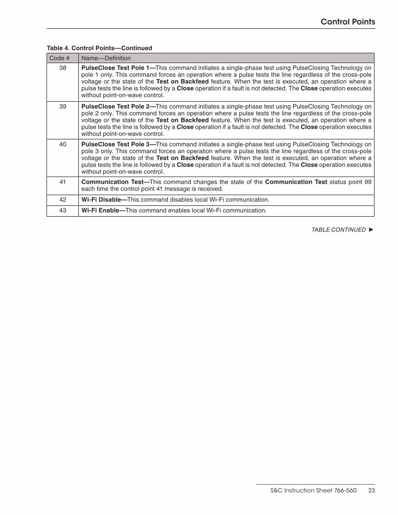
38 PulseClose Test Pole 1—This command initiates a single-phase test using PulseClosing Technology on pole 1 only . This command forces an operation where a pulse tests the line regardless of the cross-pole voltage or the state of the Test on Backfeed feature . When the test is executed, an operation where a pulse tests the line is followed by a Close operation if a fault is not detected . The Close operation executes without point-on-wave control .
39 PulseClose Test Pole 2—This command initiates a single-phase test using PulseClosing Technology on pole 2 only . This command forces an operation where a pulse tests the line regardless of the cross-pole voltage or the state of the Test on Backfeed feature . When the test is executed, an operation where a pulse tests the line is followed by a Close operation if a fault is not detected . The Close operation executes without point-on-wave control .
40 PulseClose Test Pole 3—This command initiates a single-phase test using PulseClosing Technology on pole 3 only . This command forces an operation where a pulse tests the line regardless of the cross-pole voltage or the state of the Test on Backfeed feature . When the test is executed, an operation where a pulse tests the line is followed by a Close operation if a fault is not detected . The Close operation executes without point-on-wave control .
41 Communication Test—This command changes the state of the Communication Test status point 99 each time the control point 41 message is received .
42 Wi-Fi Disable—This command disables local Wi-Fi communication .
43 Wi-Fi Enable—This command enables local Wi-Fi communication .
TABLE CONTINUED ▶

24 S&C Instruction Sheet 766-560
Control Points
Table 4. Control Points—Continued
Code # Name—Definition
44 Clear Trip Indicators—This command clears the points listed below if they are set when it is received .
Status Points ClearedPoint Code Description
31 Trip on Loss of Energy
35 Overcurrent Current Trip, Pole 1
36 Overcurrent Current Trip, Pole 2
37 Overcurrent Current Trip, Pole 3
38 Overcurrent Trip, Any Pole
39 Tripped to Lockout
41 Voltage Trip
43 Frequency Trip
45 Sectionalizing Trip
54 Close Blocked by Synch Check
55 Pulse Detected a Fault
61 IntelliTeam Fault Pole 1
62 IntelliTeam Fault Pole 2
63 IntelliTeam Fault Pole 3
77 Overcurrent Trip—Sensitive Earth Fault
78 Tripped to Lockout SEF
85 Close Blocked, Pulse Unavailable
88 Tripped to Lockout—Pole 1
89 Tripped to Lockout—Pole 2
90 Tripped to Lockout—Pole 3
91 Pulse Detected Fault—Pole 1
92 Pulse Detected Fault—Pole 2
93 Pulse Detected Fault—Pole 3
111 Close Blocked, Insufficient Energy
115 Ground Overcurrernt Trip
116 Negative Sequence Overcurrent Trip
117 Definite Time Overcurrent Trip
119 Overcurrent Fault Detected
121 LoopRest Cls Blk’d, UnderFreq
122 Any Automatic Timer in Progress
158 Reserved .
TABLE CONTINUED ▶

S&C Instruction Sheet 766-560 25
Control Points
Table 4. Control Points—Continued
Code # Name—Definition
44 Cont .
Status Points Cleared—ContinuedPoint Code Description
159 Reserved .
160 Reserved .
161 Reserved .
162 Reserved .
163 Reserved .
164 Reserved .
165 Reserved .
166 Reserved .
Analog Input Points Set To Zero
Point Code Description
14 Fault Current, Pole 1, Time of Trip
15 Fault Current, Pole 2, Time of Trip
16 Fault Current, Pole 3, Time of Trip
57 Latched Overcurrent, Pole 1
58 Latched Overcurrent, Pole 2
59 Latched Overcurrent, Pole 3
61 Averaged Current, Pole 1
62 Averaged Current, Pole 2
63 Averaged Current, Pole 3
64 Averaged Residual Current
45 Wi-Fi Enable/Disable—Toggles the state of local Wi-Fi communication .
46 Clear Latched Overcurrent Status—Clears the Latch Overcurrent status point 119 if it is set when this command is received .
47 Clear Warnings—SCADA—Clears all warning flags . Errors and alarms are not affected . The Active Warnings function will reassert in approximately one second .
48 Clear Alarms—SCADA—Clears all alarm flags . Errors and warnings are not affected . The Active Alarms function will reassert in approximately one second .
TABLE CONTINUED ▶

26 S&C Instruction Sheet 766-560
Table 4. Control Points—Continued
Code # Name—Definition
49 Pulse Test—This command initiates a three-phase test using PulseClosing Technology, which executes a point-on-wave pulse and inverse pulse to evaluate the line . The interrupters will remain open at the end of the test . No action is taken when the test does not find a fault . When a fault is detected by both pulses, the message “Fault-Pulseclosing” is displayed on the Operation screen, and the corresponding status points 55, 91, 92, and 93 are set .
50 Pulse Test Pole 1—This command initiates a single-phase test using PulseClosing Technology on pole 1 that executes a point-on-wave pulse and inverse pulse . The interrupter will remain open at the end of the test . See control point 49 for fault indications .
51 Pulse Test Pole 2—This command initiates a single-phase test using PulseClosing Technology on pole 2 that executes a point-on-wave pulse and inverse pulse . The interrupter will remain open at the end of the test . See control point 49 for fault indications .
52 Pulse Test Pole 3—This command initiates a single-phase test using PulseClosing Technology on pole 3 that executes a point-on-wave pulse and inverse pulse . The interrupter will remain open at the end of the test . See control point 49 for fault indications .
53 Enable/Block Open Source Sectionalizing—When the Open-Source Sectionalizing element is set to the Yes, IntelliTeam SG, or Loop Only setting, this command will enable or disable the Open-Source Sectionalizing element . When the Open-Source Sectionalizing element is set to the Yes, IntelliTeam SG, or Loop Only setting, the Open-Source Sectionalizing element will default to enabled after a control restart .
54 Clear IntelliLink Intrusion—This command clears the IntelliLink Intrusion status point .
55 Clear Remote PR Status—This command clears the Prohibit Restoration Remotely Transmitted status point . Control point = 0x1F00
56 Clear Remote Enable Restoration Status—This command clears the Enable Restoration Remotely Transmitted status point . Control point = 0x1F01
57 Remote Transmit Enable Restoration—When received, the device clears the Prohibit Restoration state locally (only if Hot Line Tag, Frequency Trip, or Manual Operation states are not active) and then sends a Clear Prohibit Restoration command to all devices in the Remote Prohibit Restoration Transmit List table . The Enable Remote Transmit from SCADA P.R. setting must be enabled to perform this action . Control point = 0x1F02
58 Initiate Transfer Trip—This command sets the Transfer Trip state on a single device . The device issues a command to Open the switch in Automatic mode (not a manual operation) and verifies the operation . If an Open state is confirmed, the device then activates the Prohibit Restoration state on the team facing the DG source (unless it’s a DG team) to prevent restoration of that line segment . For the Prohibit Restoration state to be set, the receiving device must be an S&C switch control that is part of an IntelliTeam SG system . SW1 = 0x202, SW2 = 0x203
59 Enable/Disable Transfer Trip—When enabled, the local device sends an Initiate Transfer Trip command to all non-zero RTU addresses in the Remote Transfer Trip Transmit List table when placed in an Open and Lockout state because of a Protection or Automatic Sectionalizing event . When disabled, no condition will result in sending an Initiate Transfer Trip command to remote devices . Control point = 0x1F03
Control Points
TABLE CONTINUED ▶

S&C Instruction Sheet 766-560 27
Table 4. Control Points—Continued
Code # Name—Definition
60 Enable/Disable Remote PR from Local—When enabled, a local Prohibit Restoration command (via the front panel or IntelliLink software screen) will place the device in a Prohibit Restoration state and then transmit the Prohibit Restoration command to all devices in the Remote Prohibit Restoration Transmit list . Control point = 0x1F04
61 Enable/Disable Remote PR from SCADA—When enabled, the device will enter a Prohibit Restoration state and then transmit a Prohibit Restoration command to all devices in the Remote Prohibit Restoration Transmit list if any the following states are active: Hot Line Tag, Frequency Trip, or Manual Operation, or if the Prohibit Restoration state is activated from a SCADA command . Control point = 0x1F05
62 Clear Manual Op Any State—When executed, the manual operation on a device is cleared and the device goes into the Ready state . The device can be in an abnormal state (i .e . abnormally open or abnormally closed) or in its normal state (normally open or normally closed) .
Control Points

28 S&C Instruction Sheet 766-560
Table 5. Group O Objects
Variation Variation Name Name—Definition
204 Device location longitude
This is the longitude of the control provided by GPS in decimal degree based on the WGS84 reference . A value of zero is returned when a GPS signal is not available, the Fix Quality setting is in the Invalid state, or no GPS module is installed . When the GPS module is installed the present position is always returned, even when GPS mode is not selected for the Time Source Synchronization setpoint on the Setup>General>Time screen .
205 Device location latitude
This is the latitude of the control provided by GPS in decimal degree based on the WGS84 reference . A value of zero is returned when a GPS signal is not available, the Fix Quality setting is in the Invalid state, or no GPS module is installed . When the GPS module is installed the present position is always returned, even when GPS mode is not selected for the Time Source Synchronization setpoint on the Setup>General>Time screen .
242 Device manufacturer’s software version
The S&C implementation will return a string containing the MCU Application, MCU EOS, DSP Application, and DSP EOS version numbers . The following is an example of the string that will be returned: “003 .003 .004 .003 060 .001 .021 .043 003 .003 .003 .000 050 .008 .000 .014,” representing MCU Application 3 .3 .4 .3, MCU EOS 60 .1 .21 .43, DSP Application 3 .3 .3 .0, and DSP EOS 50 .8 .0 .14 .
248 Device serial number
The S&C implementation will return a string containing the Protection and Control Module serial number and the IntelliRupter fault interrupter serial number . The following is an example of the string that will be returned: “4540-0000-000051 08-0001769 .”
Group 0 Objects

S&C Instruction Sheet 766-560 29
This implementation of DNP and this section of documentation conform to the document “DNP V3.00 Subset Definitions, Version 2.00,” available from the DNP Users Group.
Table 6 describes the compatibility of S&C’s implementation of DNP with other devices.
Table 6. Device Profile Description
DNP 3
DEVICE PROFILE DOCUMENT
Vendor Name: S&C Electric Company
Device Name: IntelliRupter® PulseCloser® Fault Interrupter
Highest DNP Level Supported:
For Requests - Level 2
For Responses - Level 2
Device Function:
_ _ _ Master X Slave
Notable objects, functions, and/or qualifiers supported in addition to the Highest DNP Levels Supported (the complete list is described in the attached table):
8-Bit Unsigned Integers
_ _ _ _ _ _ _ _ _ _ _ _ _ _ _ _ _ _ _ _ _ _ _ _ _ _ _ _ _ _ _ _ _ _ _ _ _ _ __ _ _ _ _ _ _ _ _ _ _ _ _ _ _ _ _ _ _ _ _ _ _ _ _ _ _ _ _ _ _ _ _ _ _ _ _ _ _
_ _ _ _ _ _ _ _ _ _ _ _ _ _ _ _ _ _ _ _ _ _ _ _ _ _ _ _ _ _ _ _ _ _ _ _ _ _ __ _ _ _ _ _ _ _ _ _ _ _ _ _ _ _ _ _ _ _ _ _ _ _ _ _ _ _ _ _ _ _ _ _ _ _ _ _ _
Maximum Data Link Frame Size (bytes)
Transmitted - 292
Received - 292
Max Application Fragment Size (bytes)
Transmitted - 2048
Received - 2048
Maximum Data link Re-tries:
X None
_ _ Fixed at _ _ _ _ _ _ _ _
_ _ Configurable, range 1 to 25
Maximum Application Layer Re-tries:
_ _ None
_ _ Fixed at _ _ _ _ _ _ _ _
X Configurable, range 0 to 10
Requires Data Link Layer Confirmation:
X Never
_ _ Always
_ _ Sometimes If “Sometimes,” when?
_ _ Configurable If “Configurable,” how?
DNP Implementation
TABLE CONTINUED ▶
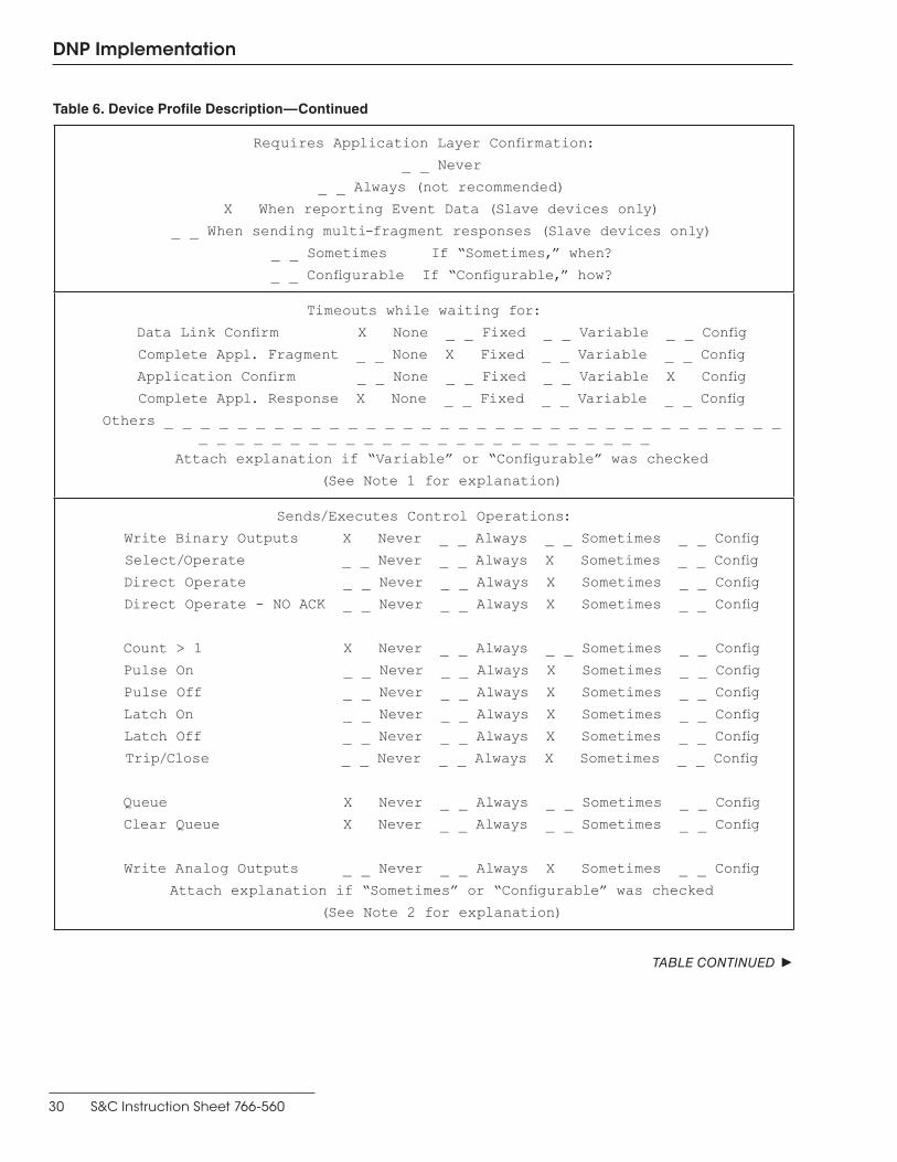
30 S&C Instruction Sheet 766-560
DNP Implementation
Requires Application Layer Confirmation:
_ _ Never
_ _ Always (not recommended)
X When reporting Event Data (Slave devices only)
_ _ When sending multi-fragment responses (Slave devices only)
_ _ Sometimes If “Sometimes,” when?
_ _ Configurable If “Configurable,” how?
Timeouts while waiting for:
Data Link Confirm X None _ _ Fixed _ _ Variable _ _ Config
Complete Appl. Fragment _ _ None X Fixed _ _ Variable _ _ Config
Application Confirm _ _ None _ _ Fixed _ _ Variable X Config
Complete Appl. Response X None _ _ Fixed _ _ Variable _ _ Config
Others _ _ _ _ _ _ _ _ _ _ _ _ _ _ _ _ _ _ _ _ _ _ _ _ _ _ _ _ _ _ _ _ _ __ _ _ _ _ _ _ _ _ _ _ _ _ _ _ _ _ _ _ _ _ _ _ _ _
Attach explanation if “Variable” or “Configurable” was checked
(See Note 1 for explanation)
Sends/Executes Control Operations:
Write Binary Outputs X Never _ _ Always _ _ Sometimes _ _ Config
Select/Operate _ _ Never _ _ Always X Sometimes _ _ Config
Direct Operate _ _ Never _ _ Always X Sometimes _ _ Config
Direct Operate - NO ACK _ _ Never _ _ Always X Sometimes _ _ Config
Count > 1 X Never _ _ Always _ _ Sometimes _ _ Config
Pulse On _ _ Never _ _ Always X Sometimes _ _ Config
Pulse Off _ _ Never _ _ Always X Sometimes _ _ Config
Latch On _ _ Never _ _ Always X Sometimes _ _ Config
Latch Off _ _ Never _ _ Always X Sometimes _ _ Config
Trip/Close _ _ Never _ _ Always X Sometimes _ _ Config
Queue X Never _ _ Always _ _ Sometimes _ _ Config
Clear Queue X Never _ _ Always _ _ Sometimes _ _ Config
Write Analog Outputs _ _ Never _ _ Always X Sometimes _ _ Config
Attach explanation if “Sometimes” or “Configurable” was checked
(See Note 2 for explanation)
TABLE CONTINUED ▶
Table 6. Device Profile Description—Continued

S&C Instruction Sheet 766-560 31
DNP Implementation
Maximum Select/Execute Delay Time:
_ _ Not Applicable
_ _ Fixed at _ _ _ _ _ seconds
X Configurable, range 1 to 100 seconds
FILL OUT THE FOLLOWING ITEM FOR MASTER DEVICES ONLY:
Master Expects Binary Input Change Events:
_ _ Either time-tagged or non-time-tagged for a single event
_ _ Both time-tagged and non-time-tagged for a single event
_ _ Configurable (attach explanation)
FILL OUT THE FOLLOWING ITEMS FOR SLAVE DEVICES ONLY:
TimeSynch Information
a.) TimeSynch Period
_ _ Never
_ _ Fixed at _ _ _ _ _ seconds
X Configurable, range 60 to 3600 seconds, then to 60 hours in
1 hour increments
b.) Maximum time base drift over a 10 minute interval: _ _ _ _ 21 _ ms
(21 ms for real-time clock, < 1 ms for GPS)
c.) Maximum Internal Time Reference Error when set via DNP: _ _ _ _ 1 _ ms
d.) Maximum Delay Measurement error: _ _ _ _ 2 _ ms
e.) Maximum Response time: _ _ _ _ 2 _ ms
Reports Binary Input Change Events when no specific variation requested:
_ _ Never
X Only time-tagged
_ _ Only non-time-tagged
_ _ Configurable to send both
Reports time-tagged Binary Input Change Events when no specific variation
requested:
_ _ Never
X Binary Input Change with Time
_ _ Bin In Change Relative Time
_ _ Configurable (explain)
Sends Unsolicited Responses:
_ _ Never
X Configurable (explain)
_ _ Only certain objects
_ _ Sometimes (explain)
_ _ ENABLE/DISABLE UNSOLICITED
Function codes supported
(See Note 3)
Sends Static Data in Unsolicited Responses:
X Never
_ _ When Device Restarts
_ _ When Status Flags Change
No other options are permitted.
(See Note 3)
TABLE CONTINUED ▶
Table 6. Device Profile Description—Continued

32 S&C Instruction Sheet 766-560
DNP Implementation
Supports Collision Avoidance:
X Never
_ _ Always
_ _ Configurable (attach explanation)
Collision Avoidance Detection Method:
X Not Applicable
_ _ Link Activity
_ _ DCD - With aid of external device
_ _ DCD - Without aid of external
device
Default Counter Object/Variation:
X No Counters Reported
_ _ Configurable (explain)
_ _ Default Object - 20
Default Variation - 5
_ _ Point-by-point list attached
Counters Roll Over at:
X No Counters Reported
_ _ Configurable (explain)
_ _ 16 Bits
_ _ 32 Bits
_ _ Other Value _ _ _ _ _ _ _ _ _ _
_ _ Point-by-point list attached
Analog Deadbands:
_ _ Fixed
Configurable:
X Per Point
_ _ Per Analog Type
_ _ Global
Configurable Analog Deadbands:
_ _ Not Applicable
X Configuration Software
_ _ Using Object 34 from the master
station
_ _ Both configuration software and
Object 34
Are the updated deadband values preserved through a device reset:
X YES
_ _ NO
The maximum number of objects supported in a single control request for objects
12 and 41.
Number of objects allowed for object 12: 1
Number of objects allowed for object 41: 1
Table 6. Device Profile Description—Continued
TABLE CONTINUED ▶

S&C Instruction Sheet 766-560 33
Ability for REMOTE/LOCAL control mode:
_ _ Not Applicable
_ _ Per point
_ _ Per object
X Global
Is the Event Buffer size configurable:
X NO fixed size: _ _ 64 _ each
for binary and analog
_ _ YES range: _ _ _ _ _
Configurable Per Class buffer:
X NO
_ _ YES
Are the updated ENABLE/DISABLE unsolicited settings saved through a
device reset:
_ _ YES
X NO
Self Address Support using address 0xFFFC:
X YES (only allowed if configurable)
_ _ NO
Source Address Filtering:
X Not Supported
_ _ Configurable (attach explanation)
Sends Multi-Fragment Responses (Slave Only): X Yes _ _ No
DNP Implementation
Table 6. Device Profile Description—Continued

34 S&C Instruction Sheet 766-560
DNP Implementation
Note 1: Timeouts While Waiting for ConfirmationsFor an unsolicited response when an application layer response confirmation is requested, the switch control waits before sending another response/confirmation attempt (if the retry number has not been reached) or stopping the confirmation process.
Set the Time Delay Between Retries function with the IntelliLink Setup Software or via SCADA. See Instruction Sheet 766-530, “S&C IntelliRupter® PulseCloser® Fault Interrupter: Setup,” for more information.
Note 2: Control Operations ExecutedFor all Binary Output Relay operations and Analog Output operations, the allowed control functions are:
• Select/Operate
• Direct Operate
• Direct Operate No Ack
The master station can choose which of these three functions to use at any given time.
Use the Trip/Close bits for these functions in the control block. Set the Count value to “1” and the Code value to “NUL” (0) or “1.” The switch control ignores the On-Time and Off-Time values and the Queue and Clear flags in the control code.
For all momentary bit operations, use the Pulse On function. When using the Pulse On function, set the Count value to “1” and the Code value to “1.” Set the Trip/Close state to “NUL” (0). The switch control ignores the On-Time and Off-Time values and the Queue and Clear flags in the control code.
For all latching bit operations, use either the Latch On or Latch Off function. For either function, set the Count value in the control block to “1.” Set the Code value to “3” for Latch On mode or “4” for Latch Off mode. Set the Trip/Close state to “NUL” (0). The switch control ignores the On-Time and Off-Time values and the Queue and Clear flags in the control code.
For more details, see the “Control Relay Output Block” section of the document object library in “IEEE std 1815™-2012” available from the DNP Users Group.
Note 3: Unsolicited ResponsesThe IntelliRupter fault interrupter returns unsolicited responses to the configured master station address when a change occurs in any mapped status point that is configured for event reporting, when the configured deadband is exceeded in any mapped analog input point that is configured for event reporting. Unsolicited responses must be enabled and disabled in the IntelliLink software. Enable data-filled unsolicited responses from SCADA with function code 20 or disable data-filled unsolicited responses with function code 21.
Control the delivery of unsolicited response messages by adjusting the Unsolicited Transmit Delay Event Count and the Unsolicited Transmit Delay Time settings.
Note 4: Cold RestartTo send an IntelliRupter fault interrupter the Cold Restart command, send DNP function code 13 (0x0D). A Cold Restart command is similar to an IntelliRupter fault interrupter powering up after a long-term power loss. When the IntelliRupter fault interrupter receives function code 13, it immediately responds with a Delay Time DNP3 object, g52v1, and then initiates the restart. The delay time sent (30 seconds) is the time required for the restart, during which the IntelliRupter fault interrupter will be unable to respond to DNP requests.
For more information see section 4.4.9 in “IEEE std 1815™-2012.
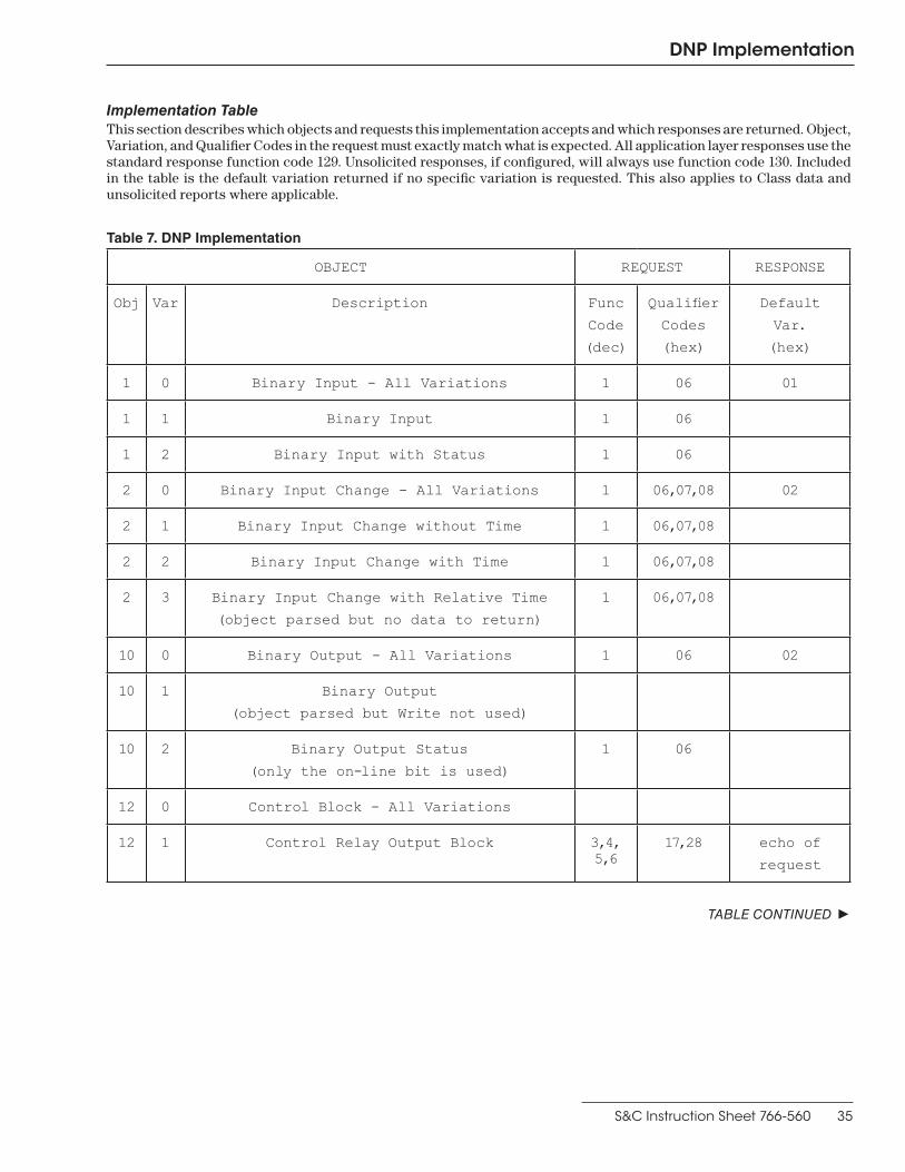
S&C Instruction Sheet 766-560 35
DNP Implementation
Implementation TableThis section describes which objects and requests this implementation accepts and which responses are returned. Object, Variation, and Qualifier Codes in the request must exactly match what is expected. All application layer responses use the standard response function code 129. Unsolicited responses, if configured, will always use function code 130. Included in the table is the default variation returned if no specific variation is requested. This also applies to Class data and unsolicited reports where applicable.
Table 7. DNP Implementation
OBJECT REQUEST RESPONSE
Obj Var Description Func
Code
(dec)
Qualifier
Codes
(hex)
Default
Var.
(hex)
1 0 Binary Input - All Variations 1 06 01
1 1 Binary Input 1 06
1 2 Binary Input with Status 1 06
2 0 Binary Input Change - All Variations 1 06,07,08 02
2 1 Binary Input Change without Time 1 06,07,08
2 2 Binary Input Change with Time 1 06,07,08
2 3 Binary Input Change with Relative Time
(object parsed but no data to return)
1 06,07,08
10 0 Binary Output - All Variations 1 06 02
10 1 Binary Output
(object parsed but Write not used)
10 2 Binary Output Status
(only the on-line bit is used)
1 06
12 0 Control Block - All Variations
12 1 Control Relay Output Block 3,4, 5,6
17,28 echo of
request
TABLE CONTINUED ▶

36 S&C Instruction Sheet 766-560
DNP Implementation
OBJECT REQUEST RESPONSE
Obj Var Description Func
Code
(dec)
Qualifier
Codes
(hex)
Default
Var.
(hex)
12 2 Pattern Control Block
12 3 Pattern Mask
20 0 Binary Counter - All Variations
20 1 32-Bit Binary Counter
20 2 16-Bit Binary Counter
20 3 32-Bit Delta Counter
20 4 16-Bit Delta Counter
20 5 32-Bit Binary Counter without Flag
20 6 16-Bit Binary Counter without Flag
20 7 32-Bit Delta Counter without Flag
20 8 16-Bit Delta Counter without Flag
21 0 Frozen Counter - All Variations
21 1 32-Bit Frozen Counter
21 2 16-Bit Frozen Counter
21 3 32-Bit Frozen Delta Counter
21 4 16-Bit Frozen Delta Counter
21 5 32-Bit Frozen Counter with Time of Freeze
21 6 16-Bit Frozen Counter with Time of Freeze
TABLE CONTINUED ▶
Table 7. DNP Implementation—Continued

S&C Instruction Sheet 766-560 37
DNP Implementation
OBJECT REQUEST RESPONSE
Obj Var Description Func
Code
(dec)
Qualifier
Codes
(hex)
Default
Var.
(hex)
21 7 32-Bit Frozen Delta Counter
with Time of Freeze
21 8 16-Bit Frozen Delta Counter
with Time of Freeze
21 9 32-Bit Frozen Counter without Flag
21 10 16-Bit Frozen Counter without Flag
21 11 32-Bit Frozen Delta Counter without Flag
21 12 16-Bit Frozen Delta Counter without Flag
22 0 Counter Change Event - All Variations
22 1 32-Bit Counter Change Event without Time
22 2 16-Bit Counter Change Event without Time
22 3 32-Bit Delta Counter Change Event w/o Time
22 4 16-Bit Delta Counter Change Event w/o Time
22 5 32-Bit Counter Change Event with Time
22 6 16-Bit Counter Change Event with Time
22 7 32-Bit Delta Counter Change Event w/ Time
22 8 16-Bit Delta Counter Change Event w/ Time
23 0 Frozen Counter Event - All Variations
23 1 32-Bit Frozen Counter Event without Time
TABLE CONTINUED ▶
Table 7. DNP Implementation—Continued

38 S&C Instruction Sheet 766-560
DNP Implementation
OBJECT REQUEST RESPONSE
Obj Var Description Func
Code
(dec)
Qualifier
Codes
(hex)
Default
Var.
(hex)
23 2 16-Bit Frozen Counter Event without Time
23 3 32-Bit Frozen Delta Counter Event w/o Time
23 4 16-Bit Frozen Delta Counter Event w/o Time
23 5 32-Bit Frozen Counter Event with Time
23 6 16-Bit Frozen Counter Event with Time
23 7 32-Bit Frozen Delta Counter Event w/ Time
23 8 16-Bit Frozen Delta Counter Event w/ Time
30 0 Analog Input - All Variations 1 06 04
30 1 32-Bit Analog Input 1 06
30 2 16-Bit Analog Input 1 06
30 3 32-Bit Analog Input without Flag 1 06
30 4 16-Bit Analog Input without Flag 1 06
31 0 Frozen Analog Input - All Variations
31 1 32-Bit Frozen Analog Input
31 2 16-Bit Frozen Analog Input
31 3 32-Bit Frozen Analog Input
with Time of Freeze
31 4 16-Bit Frozen Analog Input
with Time of Freeze
TABLE CONTINUED ▶
Table 7. DNP Implementation—Continued

S&C Instruction Sheet 766-560 39
OBJECT REQUEST RESPONSE
Obj Var Description Func
Code
(dec)
Qualifier
Codes
(hex)
Default
Var.
(hex)
31 5 32-Bit Frozen Analog Input without Flag
31 6 16-Bit Frozen Analog Input without Flag
32 0 Analog Change Event - All Variations 1 06,07,08 02
32 1 32-Bit Analog Change Event without Time 1 06,07,08
32 2 16-Bit Analog Change Event without Time 1 06,07,08
32 3 32-Bit Analog Change Event with Time 1 06,07,08
32 4 16-Bit Analog Change Event with Time 1 06,07,08
33 0 Frozen Analog Event - All Variations
33 1 32-Bit Frozen Analog Event without Time
33 2 16-Bit Frozen Analog Event without Time
33 3 32-Bit Frozen Analog Event with Time
33 4 16-Bit Frozen Analog Event with Time
40 0 Analog Output Status - All Variations 1 06 02
40 1 32-Bit Analog Output Status 1 06
40 2 16-Bit Analog Output Status 1 06
41 0 Analog Output Block - All Variations
41 1 32-Bit Analog Output Block 3,4,
5,6
17,28 echo of
request
41 2 16-Bit Analog Output Block 3,4,
5,6
17,28 echo of
request
TABLE CONTINUED ▶
DNP Implementation
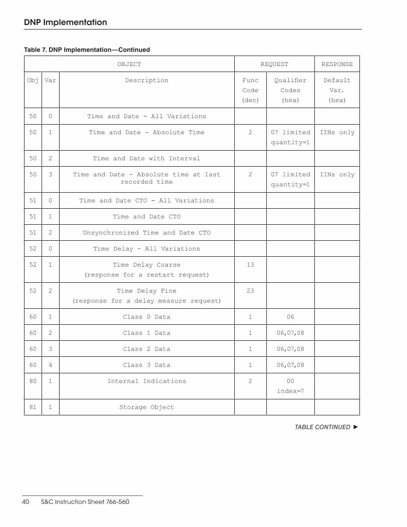
40 S&C Instruction Sheet 766-560
DNP Implementation
OBJECT REQUEST RESPONSE
Obj Var Description Func
Code
(dec)
Qualifier
Codes
(hex)
Default
Var.
(hex)
50 0 Time and Date - All Variations
50 1 Time and Date - Absolute Time 2 07 limited
quantity=1
IINs only
50 2 Time and Date with Interval
50 3 Time and Date - Absolute time at last recorded time
2 07 limited
quantity=1
IINs only
51 0 Time and Date CTO - All Variations
51 1 Time and Date CTO
51 2 Unsynchronized Time and Date CTO
52 0 Time Delay - All Variations
52 1 Time Delay Coarse
(response for a restart request)
13
52 2 Time Delay Fine
(response for a delay measure request)
23
60 1 Class 0 Data 1 06
60 2 Class 1 Data 1 06,07,08
60 3 Class 2 Data 1 06,07,08
60 4 Class 3 Data 1 06,07,08
80 1 Internal Indications 2 00
index=7
81 1 Storage Object
TABLE CONTINUED ▶
Table 7. DNP Implementation—Continued

S&C Instruction Sheet 766-560 41
DNP Implementation
OBJECT REQUEST RESPONSE
Obj Var Description Func
Code
(dec)
Qualifier
Codes
(hex)
Default
Var.
(hex)
82 1 Device Profile
83 1 Private Registration Object
83 2 Private Registration Object Descriptor
90 1 Application Identifier
100 1 Short Floating Point
100 2 Long Floating Point
100 3 Extended Floating Point
101 1 Small Packed Binary-Coded Decimal
101 2 Medium Packed Binary-Coded Decimal
101 3 Large Packed Binary-Coded Decimal
102 0 8-Bit Unsigned Integer
102 1 8-Bit Unsigned Integer 1,2 03,04,05
No Object 13
No Object 23
No Object 24
Table 7. DNP Implementation—Continued