dnp3 master ethernet driver - kepware.com · dnp3masterethernetdriver objectgroup30-analoginputs 52...
TRANSCRIPT

DNP3 Master Ethernet Driver
© 2018 PTC Inc. All Rights Reserved.

DNP3 Master Ethernet Driver
Table of Contents
DNP3 Master Ethernet Driver 1
Table of Contents 2
DNP3 Master Ethernet Driver 10
Overview 10
Setup 11
Channel Properties — General 11
Channel Properties — Ethernet Communications 12
Channel Properties — Write Optimizations 12
Channel Properties — Advanced 13
Channel Properties — Communication Serialization 14
Channel Properties — Communications 15
Channel Properties — Timing 15
Timing and Other Considerations 16
Device Properties — General 17
Device Properties — ScanMode 19
Device Properties — Tag Generation 19
Device Properties — Auto-Demotion 21
Device Properties — Communications 22
Device Properties — Polling 24
Device Properties — Unsolicited 25
Device Properties — Event Playback 25
Device Properties — Tag Import 26
Device Properties — Authentication 27
Device Properties — Update Key Authentication 28
Device Properties — File Control 29
Device Properties — Advanced 31
Device Properties — Redundancy 32
Data Types Description 33
Address Descriptions 34
Object Group 0 - Device Attributes 37
Object Group 1- Binary Inputs 38
Object Group 3 - Double Bit Inputs 40
Object Group 10 - Binary Outputs 43
Object Group 12 - Binary Output Commands 45
Object Group 20 - Counters 47
Object Group 21 - Frozen Counters 49
www.ptc.com
2
DNP3 Master Ethernet Driver
Object Group 30 - Analog Inputs 52
Object Group 34 - Analog Inputs Deadband 54
Object Group 40 - Analog Outputs 55
Object Group 41 - Analog Output Commands 58
Object Group 50 - Time and Date 58
Object Group 60 - Class Poll Data Request 59
Object Group 70 - File Identifiers 60
Object Group 80 - Internal Indications 61
Object Group 87 - Data Sets 63
Object Group 110 - Octet String Object 64
Object Group 120 - Authentication Object 65
Other Object Groups 67
Internal Tags 67
Special Tags 69
Device Profile 69
Device Properties— Identification 69
Link Layer 72
Application Layer 73
Masters Only 73
Security Parameters 74
Implementation Tables 76
Error Descriptions 86
Address ValidationMessages 86
Address <address> is not valid on device <channel> <device>. 86
Address <address> is out of range for the specified device or register. 86
Data type <type> is not valid for device address <address>. 86
Device address <address> contains a syntax error. 87
Device address <address> is read only. 87
Authentication ErrorMessages 87
Secure authentication failure on device <channel.device>. Device does not support the functioncode (IIN2.0). 88
Secure authentication failure on device <channel.device>. Key Status Request communicationsfailure. Session keys are not valid. 88
Secure authentication failure on device <channel.device>. Key Status Request non-authentic.Session Keys are not valid. 88
Secure authentication failure on device <channel.device>. Aggressive Mode Response indicatesimproper authentication. 89
Secure authentication failure on device <channel.device>. Challenge Reply indicates improper 89
www.ptc.com
3
DNP3 Master Ethernet Driver
authentication.
Secure authentication failure on device <channel.device>. User= <User Number>, AssocID=<Association ID>, Sequence= <Sequence Number>. RX Error Code= <error code>-<errordescription>. 89
Secure authentication failure on device <channel.device>. User= <User Number>, AssocID=<Association ID>, Sequence= <Sequence Number>. TX Error Code= <error code>-<errordescription>. 90
Secure authentication failure on device <device>. Key Status Request response status code:<status code>. 91
Automatic Tag DatabaseGeneration ErrorMessages 91
Unable to add data set <data set index> on device <device name>. Data set has <number ofelements> elements. The maximum number of elements allowed is <max. elements>. 92
Unable to generate a tag database for device <device>. Channel is not open. 92
Unable to generate a tag database for device <device>. Session is not open. 92
Unable to generate a tag database for device <driver>. The device is not responding. 92
Unable to read device attribute set <set number>. No tags added on device <device>. 93
Device StatusMessages 93
<Item description> on device <device> has been auto-demoted. 94
<Item description> on device <device> has been auto-promoted to determine if it can becompleted. 94
Added <tag count> data set tag(s). 95
Data Set write of value <value to be written> pending on tag address <address> on device<device>. 95
Device <device> does not support the LAN Time Sync Style Record Current Time Function Code24. 95
Device <device> does not support the LAN Time Sync Style write to object group 50, variation 3. 96
Device <device> indicated an event buffer overflow (IIN 2.3). 96
Device <device> indicated it restarted (IIN 1.7). 96
Device <device> initialization completed. 97
Device <device> requested time synchronization (IIN 1.4). 97
Device <device> is restarting. 97
Device <device name> is not responding. 98
Failed to resolve destination host <host name> on channel <channel name>. 98
The Keep-Alive Interval with UDP Protocol on device <device> was overridden. 99
Reachedmax. events per point for object group <object group> point <data index> on device<device>. 99
Request failed on device <device>. Device does not support the function code (IIN2.0). 99
Request to enable unsolicited messaging failed on device <device>. 100
Unable to bind to local address (IP: xxx.xxx.xxx.xxx, Source Port: x). 100
Unable to read point(s) <OBJ.VAR.IDX> on device <device>. Failed to initialize communicationstack. 101
www.ptc.com
4
DNP3 Master Ethernet Driver
Unable to read point(s) <OBJ.VAR.IDX> on device <device>. Internal Error occurred. 101
Unable to read point(s) <OBJ.VAR.IDX – OBJ.VAR.IDX> on device <device>. Failed to initializecommunication stack. 101
Unable to read point(s) <OBJ.VAR.IDX – OBJ.VAR.IDX> on device <device>. Internal erroroccurred. 101
Unable to read tag <tag address> on device <device>. Device indicates one or more exceptionconditions (DNP flags byte=<hexadecimal byte> - <DNP flag exception list). 102
Unable to receive response from device <device> within timeout. Either the request or responsecould not be completed or the response is invalid. 102
Unable to write to address <address> on device <device>. Failed to initialize communicationstack. 103
Unable to write to address <address> on device <device>. Internal error occurred. 103
Write complete to data set <index> on device <device>. 103
DriverMessages 104
Winsock initialization failed (OS Error = n). 104
Winsock shutdown failed (OS Error = n). 104
Winsock V1.1 or higher must be installed to use the driver. 104
DNP-Specific Messages 105
Read Errors 105
The returned value for tag address <tag address> in device <device name> has a length of zero.The tag value cannot be set. 106
The returned value of <date returned value> for tag address <address> in device <device> isinvalid for the <data type> tag data type. 107
The returned value of <returned numeric value> for tag address <address> in device <device> isinvalid for the <data type> tag data type. 107
The returned value of <returned numeric value> for tag address <address> in device <device> isout of range for the <data type> tag data type. 107
The returned value of <returned string value> for tag address <address> in device <device> isinvalid for the <data type> tag data type. 108
Unable to read point(s) <OBJ.VAR.IDX> on device <device>. An abnormal condition exists in thedevice (IIN1.6). 108
Unable to read point(s) <OBJ.VAR.IDX> on device <device>. Device detected corruptconfiguration (IIN2.5). 108
Unable to read point(s) <OBJ.VAR.IDX> on device <device>. Device does not support a point inthe range or other parameter error (IIN2.2). 108
Unable to read point(s) <OBJ.VAR.IDX> on device <device>. Device does not support requestedoperation for objects in the request (IIN2.1). 109
Unable to read point(s) <OBJ.VAR.IDX> on device <device>. Device does not support the functioncode (IIN2.0). 109
Unable to read point(s) <OBJ.VAR.IDX> on device <device>. Device reports that some outputpoints are in local mode (IIN1.5). 109
Unable to read point(s) <OBJ.VAR.IDX> on device <device>. Device reports that the operation is 109
www.ptc.com
5

DNP3 Master Ethernet Driver
already executing (IIN2.4).
Unable to read point(s) <OBJ.VAR.IDX> on device <device>. Session shutting down or duplicaterequest. 110
Unable to read point(s) <OBJ.VAR.IDX> on device <device>. Unable to receive response fromdevice <device> within timeout. Either the request or response could not be completed or theresponse is invalid. 110
Unable to read point(s) <OBJ.VAR.IDX> on device <device>. Unrecognized object returned inresponse. 111
Unable to read point(s) <OBJ.VAR.IDX – OBJ.VAR.IDX> on device <device>. An abnormal conditionexists in the device (IIN1.6). 111
Unable to read point(s) <OBJ.VAR.IDX – OBJ.VAR.IDX> on device <device>. Device detectedcorrupt configuration (IIN2.5). 111
Unable to read point(s) <OBJ.VAR.IDX – OBJ.VAR.IDX> on device <device>. Device does notsupport a point in the range or other parameter error (IIN2.2). 112
Unable to read point(s) <OBJ.VAR.IDX – OBJ.VAR.IDX> on device <device>. Device does notsupport requested operation for objects in the request (IIN2.1). 112
Unable to read point(s) <OBJ.VAR.IDX – OBJ.VAR.IDX> on device <device>. Device does notsupport the function code (IIN2.0). 112
Unable to read point(s) <OBJ.VAR.IDX – OBJ.VAR.IDX> on device <device>. Device reports thatsome output points are in local mode (IIN1.5). 112
Unable to read point(s) <OBJ.VAR.IDX – OBJ.VAR.IDX> on device <device>. Device reports that theoperation is already executing (IIN2.4). 113
Unable to read point(s) <OBJ.VAR.IDX – OBJ.VAR.IDX> on device <device>. Session shutting downor duplicate request. 113
Unable to read point(s) <OBJ.VAR.IDX - OBJ.VAR.IDX> on device <device>. Unable to receiveresponse from device <device> within timeout. Either the request or response could not becompleted or the response is invalid. 113
Unable to read point(s) <OBJ.VAR.IDX – OBJ.VAR.IDX> on device <device>. Unrecognized objectreturned in response. 114
Unable to read set <set index> of object group <object group> on device <device>. An abnormalcondition exists in the device (IIN1.6). 114
Unable to read set <set index> of object group <object group> on device <device>. Devicedetected corrupt configuration (IIN2.5). 114
Unable to read set <set index> of object group <object group> on device <device>. Device doesnot support a point in the range or other parameter error (IIN2.2). 115
Unable to read set <set index> of object group <object group> on device <device>. Device doesnot support requested operation for objects in the request (IIN2.1). 115
Unable to read set <set index> of object group <object group> on device <device>. Device doesnot support the function code (IIN2.0). 115
Unable to read set <set index> of object group <object group> on device <device>. Devicereports that some output points are in local mode (IIN1.5). 116
Unable to read set <set index> of object group <object group> on device <device>. Devicereports that the operation is already executing (IIN2.4). 116
Unable to read set <set index> of object group <object group> on device <device>. Session 116
www.ptc.com
6
DNP3 Master Ethernet Driver
shutting down or duplicate request.
Unable to read set <set index> of object group <object group> on device <device>.Unrecognized object returned in response. 116
Unable to read tag address <address> on device <device>. No definition for data set <index>. 117
Unable to read tag address <address> on device <device>. Response missing data. 118
Write Errors 118
Unable to write to address <address> on device <device>. Activate configuration-related statuscode <status code> - <description>. 120
Unable to write to address <address> on device <device>. An abnormal condition exists in thedevice (IIN1.6). 120
Unable to write to address <address> on device <device>. Channel response timeout must bebetween <min channel response timeout> and <max. channel response timeout>. 120
Unable to write to address <address> on device <device>. Control-related status code <statuscode>. 121
Unable to write to address <address> on device <device>. Destination <destination host>:<destination port> already in use on channel <channel>. 122
Unable to write to address <address> on device <device>. Destination port must be between<min. source port> and <max. source port>. 122
Unable to write to address <address> on device <device>. Device detected corrupt configuration(IIN2.5). 122
Unable to write to address <address> on device <device>. Device does not support a point in therange or other parameter error (IIN2.2). 123
Unable to write to address <address> on device <device>. Device does not support requestedoperation for objects in the request (IIN2.1). 123
Unable to write to address <address> on device <device>. Device does not support the functioncode (IIN2.0). 123
Unable to write to address <address> on device <device>. Device reports that some outputpoints are in local mode (IIN1.5). 123
Unable to write to address <address> on device <device>. Device reports that the operation isalready executing (IIN2.4). 124
Unable to write to address <address> on device <device>. Device Request Timeout must bebetween <min. value> and <max. value>. 124
Unable to write to address <address> on device <device>. Element index <variation> is notdefined in data set <index>. 124
Unable to write to address <address> on device <device>. Event poll interval must be between<min. value> and <max. value>. 125
Unable to write to address <address> on device <device>. File name writes have been disabled. 125
Unable to write to address <address> on device <device>. Integrity poll interval must bebetween <min. value> and <max. value>. 125
Unable to write to address <address> on device <device>. Master address <master address>already in use as slave address on device <device>. 125
Unable to write to address <address> on device <device>. Master address must be between<min. master address> and <max. master address>. 126
www.ptc.com
7
DNP3 Master Ethernet Driver
Unable to write to address <address> on device <device>. Master and slave address cannot bethe same. 126
Unable to write to address <address> on device <device>. No definition for data set <index>. 126
Unable to write to address <address> on device <device>. Protocol must be between <min.protocol> and <max. protocol>. 126
Unable to write to address <address> on device <device>. Select Operate response invalid. 127
Unable to write to address <address> on device <device>. Session shutting down or duplicaterequest. 127
Unable to write to address <address> on device <device>. Slave address <slave address>already in use on device <device>. 127
Unable to write to address <address> on device <device>. Slave address must be between <min.slave address> and <max. slave address>. 128
Unable to write to address <address> on device <device>. Source port must be between <minsource port> and <max. source port>. 128
Unable to write to address <address> on device <device>. Tag <data type> data type isincompatible with the data set element <data type> data type. 128
Unable to write to address <address> on device <device>. Unable to receive response fromdevice <device> within timeout. Either the request or response could not be completed or theresponse is invalid. 128
Unable to write to address <address> on device <device>. Unrecognized object returned inresponse. 129
Unable to write to address <address> on device <device>. Unsupported Operation Type. 129
Unable to write to address <address> on device <device>. Unsupported Trip-Close Code. 130
Unable to write to address <address> on device <device>. Write value specified is invalid orincomplete. 130
File Control Messages 131
File Transfer failure on device <device> for file index <index>. Device returned File-RelatedStatus Code <status code> - <description>. 131
File Transfer failure on device <device> for file index <index>. File size of <size> kilobytes isgreater thanmaximum file size of <maximum size> kilobytes. 132
File Transfer failure on device <device> for file index <index>. File transfer aborted by user. 133
File Transfer failure on device <device> for file index <index>. File transfer aborted due tocommunications issue. 133
File Transfer failure on device <device> for file index <index>. Local file <file name> is empty. 133
File Transfer failure on device <device> for file index <index>. Local file open failure. <local fileopen failure>. 133
File Transfer failure on device <device> for file index <index>. Session shutting down or duplicaterequest. 134
Invalid local file for file index 70.<file index>, general error. 134
Invalid Local File for File Index 70.<file index>, verify the specified path is write-enabled. 134
Invalid Local File path for File Index 70.<file index>. 135
Invalid Local File syntax for File Index 70.<file index>. 135
www.ptc.com
8

DNP3 Master Ethernet Driver
Resources 136
Index 137
www.ptc.com
9
DNP3 Master Ethernet Driver
DNP3 Master Ethernet DriverHelp version 1.200
CONTENTS
OverviewWhat is the DNP3 Master Ethernet Driver?
SetupHow do I configure channels and devices for use with this driver?
Data Types DescriptionWhat data types does this driver support?
Address DescriptionsHow do I address a data location?
Error DescriptionsWhat error messages are produced by the DNP3 Master Ethernet Driver?
Device ProfileWhere can I find more information about the device profile?
OverviewThe DNP3 Master Ethernet Driver provides a reliable way to connect DNP slave Ethernet devices to OPCClient applications; including HMI, SCADA, Historian, MES, ERP, and countless custom applications.
www.ptc.com
10
DNP3 Master Ethernet Driver
SetupIn the DNP3 protocol, a channel describes a communications path between two endpoints. DNP3 sessionsdescribe specific communications between a DNPmaster node (server channel) and a DNP slave node(server device). In the DNP3 Master Ethernet Driver, DNP sessions are represented as server devices foreach channel. The server channel describes the communications conduit over which the master and slavecommunicate. The other endpoint of the DNP channel may have one or more slave nodes available.
Communication ProtocolDistributed Network Protocol 3.0 (DNP3) via TCP or UDP
Supported DevicesAny DNP3 slave device
Maximum Channels and DevicesThe maximum number of channels supported by this driver is 1024. The maximum number of devices (perchannel) is 1024. This driver uses one socket per channel.
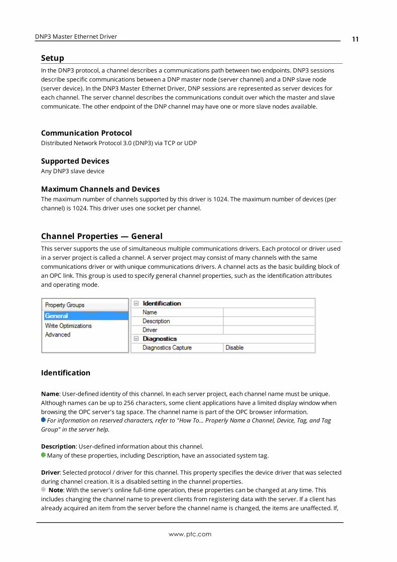
Channel Properties — GeneralThis server supports the use of simultaneous multiple communications drivers. Each protocol or driver usedin a server project is called a channel. A server project may consist of many channels with the samecommunications driver or with unique communications drivers. A channel acts as the basic building block ofan OPC link. This group is used to specify general channel properties, such as the identification attributesand operating mode.
Identification
Name: User-defined identity of this channel. In each server project, each channel name must be unique.Although names can be up to 256 characters, some client applications have a limited display window whenbrowsing the OPC server's tag space. The channel name is part of the OPC browser information.For information on reserved characters, refer to "How To... Properly Name a Channel, Device, Tag, and Tag
Group" in the server help.
Description: User-defined information about this channel. Many of these properties, including Description, have an associated system tag.
Driver: Selected protocol / driver for this channel. This property specifies the device driver that was selectedduring channel creation. It is a disabled setting in the channel properties.
Note: With the server's online full-time operation, these properties can be changed at any time. Thisincludes changing the channel name to prevent clients from registering data with the server. If a client hasalready acquired an item from the server before the channel name is changed, the items are unaffected. If,
www.ptc.com
11

DNP3 Master Ethernet Driver
after the channel name has been changed, the client application releases the item and attempts to re-acquire using the old channel name, the item is not accepted. With this in mind, changes to the propertiesshould not be made once a large client application has been developed. Utilize the User Manager to preventoperators from changing properties and restrict access rights to server features.
Diagnostics
Diagnostics Capture: When enabled, this optionmakes the channel's diagnostic information available toOPC applications. Because the server's diagnostic features require a minimal amount of overheadprocessing, it is recommended that they be utilized when needed and disabled when not. The default isdisabled.Note: This property is disabled if the driver does not support diagnostics.For more information, refer to "Communication Diagnostics" in the server help.
Channel Properties — Ethernet CommunicationsEthernet Communication can be used to communicate with devices.
Ethernet Settings
Network Adapter: Specify the network adapter to bind. When Default is selected, the operating systemselects the default adapter.
Channel Properties — Write OptimizationsAs with any OPC server, writing data to the device may be the application's most important aspect. Theserver intends to ensure that the data written from the client application gets to the device on time. Giventhis goal, the server provides optimization properties that can be used to meet specific needs or improveapplication responsiveness.
Write Optimizations
Optimization Method: controls how write data is passed to the underlying communications driver. Theoptions are:
l Write All Values for All Tags: This option forces the server to attempt to write every value to thecontroller. In this mode, the server continues to gather write requests and add them to the server'sinternal write queue. The server processes the write queue and attempts to empty it by writing datato the device as quickly as possible. This mode ensures that everything written from the client
www.ptc.com
12

DNP3 Master Ethernet Driver
applications is sent to the target device. This mode should be selected if the write operation order orthe write item's content must uniquely be seen at the target device.
l Write Only Latest Value for Non-Boolean Tags: Many consecutive writes to the same value canaccumulate in the write queue due to the time required to actually send the data to the device. If theserver updates a write value that has already been placed in the write queue, far fewer writes areneeded to reach the same final output value. In this way, no extra writes accumulate in the server'squeue. When the user stops moving the slide switch, the value in the device is at the correct value atvirtually the same time. As the mode states, any value that is not a Boolean value is updated in theserver's internal write queue and sent to the device at the next possible opportunity. This can greatlyimprove the application performance.
Note: This option does not attempt to optimize writes to Boolean values. It allows users tooptimize the operation of HMI data without causing problems with Boolean operations, such as amomentary push button.
l Write Only Latest Value for All Tags: This option takes the theory behind the second optimizationmode and applies it to all tags. It is especially useful if the application only needs to send the latestvalue to the device. This mode optimizes all writes by updating the tags currently in the write queuebefore they are sent. This is the default mode.
Duty Cycle: is used to control the ratio of write to read operations. The ratio is always based on one read forevery one to ten writes. The duty cycle is set to ten by default, meaning that ten writes occur for each readoperation. Although the application is performing a large number of continuous writes, it must be ensuredthat read data is still given time to process. A setting of one results in one read operation for every writeoperation. If there are no write operations to perform, reads are processed continuously. This allowsoptimization for applications with continuous writes versus a more balanced back and forth data flow.
Note: It is recommended that the application be characterized for compatibility with the writeoptimization enhancements before being used in a production environment.
Channel Properties — AdvancedThis group is used to specify advanced channel properties. Not all drivers support all properties; so theAdvanced group does not appear for those devices.
Non-Normalized Float Handling: A non-normalized value is defined as Infinity, Not-a-Number (NaN), or asa Denormalized Number. The default is Replace with Zero. Drivers that have native float handling maydefault to Unmodified. Non-normalized float handling allows users to specify how a driver handles non-normalized IEEE-754 floating point data. Descriptions of the options are as follows:
l Replace with Zero: This option allows a driver to replace non-normalized IEEE-754 floating pointvalues with zero before being transferred to clients.
l Unmodified: This option allows a driver to transfer IEEE-754 denormalized, normalized, non-number, and infinity values to clients without any conversion or changes.
Note: This property is disabled if the driver does not support floating point values or if it only supports theoption that is displayed. According to the channel's float normalization setting, only real-time driver tags
www.ptc.com
13

DNP3 Master Ethernet Driver
(such as values and arrays) are subject to float normalization. For example, EFM data is not affected by thissetting.
For more information on the floating point values, refer to "How To ... Work with Non-Normalized FloatingPoint Values" in the server help.
Inter-Device Delay: Specify the amount of time the communications channel waits to send new requests tothe next device after data is received from the current device on the same channel. Zero (0) disables thedelay.
Note: This property is not available for all drivers, models, and dependent settings.
Channel Properties — Communication SerializationThe server's multi-threading architecture allows channels to communicate with devices in parallel. Althoughthis is efficient, communication can be serialized in cases with physical network restrictions (such asEthernet radios). Communication serialization limits communication to one channel at a time within a virtualnetwork.
The term "virtual network" describes a collection of channels and associated devices that use the samepipeline for communications. For example, the pipeline of an Ethernet radio is the master radio. All channelsusing the same master radio associate with the same virtual network. Channels are allowed to communicateeach in turn, in a “round-robin” manner. By default, a channel can process one transaction before handingcommunications off to another channel. A transaction can include one or more tags. If the controllingchannel contains a device that is not responding to a request, the channel cannot release control until thetransaction times out. This results in data update delays for the other channels in the virtual network.
Channel-Level Settings
Virtual Network This property specifies the channel's mode of communication serialization. Optionsinclude None and Network 1 - Network 50. The default is None. Descriptions of the options are as follows:
l None: This option disables communication serialization for the channel.
l Network 1 - Network 50: This option specifies the virtual network to which the channel isassigned.
Transactions per Cycle This property specifies the number of single blocked/non-blocked read/writetransactions that can occur on the channel. When a channel is given the opportunity to communicate, thisnumber of transactions attempted. The valid range is 1 to 99. The default is 1.
Global Settings
www.ptc.com
14
DNP3 Master Ethernet Driver
l Network Mode: This property is used to control how channel communication is delegated. In LoadBalanced mode, each channel is given the opportunity to communicate in turn, one at a time. InPrioritymode, channels are given the opportunity to communicate according to the following rules(highest to lowest priority):
l Channels with pending writes have the highest priority.
l Channels with pending explicit reads (through internal plug-ins or external client interfaces)are prioritized based on the read’s priority.
l Scanned reads and other periodic events (driver specific).
The default is Load Balanced and affects all virtual networks and channels.
Devices that rely on unsolicited responses should not be placed in a virtual network. In situations wherecommunications must be serialized, it is recommended that Auto-Demotion be enabled.
Due to differences in the way that drivers read and write data (such as in single, blocked, or non-blockedtransactions); the application's Transactions per cycle property may need to be adjusted. When doing so,consider the following factors:
l Howmany tags must be read from each channel?
l How often is data written to each channel?
l Is the channel using a serial or Ethernet driver?
l Does the driver read tags in separate requests, or are multiple tags read in a block?
l Have the device's Timing properties (such as Request timeout and Fail after x successive timeouts)been optimized for the virtual network's communicationmedium?
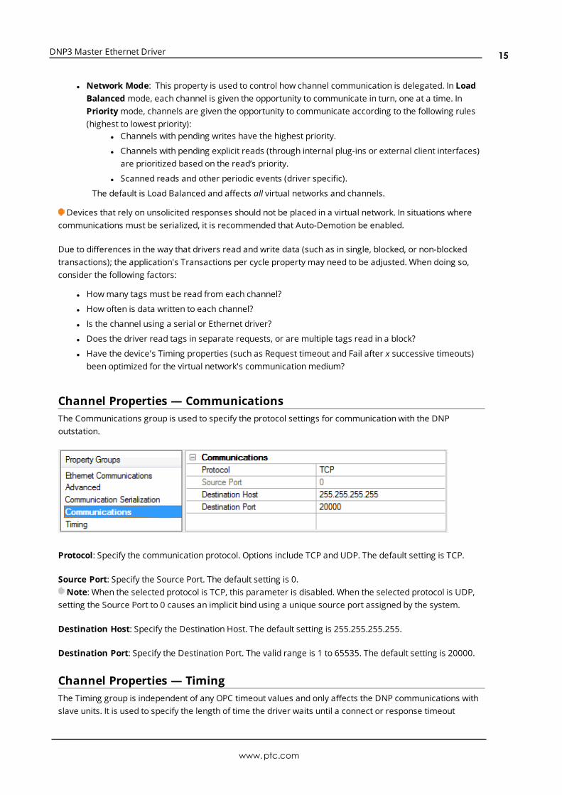
Channel Properties — CommunicationsThe Communications group is used to specify the protocol settings for communication with the DNPoutstation.
Protocol: Specify the communication protocol. Options include TCP and UDP. The default setting is TCP.
Source Port: Specify the Source Port. The default setting is 0.Note: When the selected protocol is TCP, this parameter is disabled. When the selected protocol is UDP,
setting the Source Port to 0 causes an implicit bind using a unique source port assigned by the system.
Destination Host: Specify the Destination Host. The default setting is 255.255.255.255.
Destination Port: Specify the Destination Port. The valid range is 1 to 65535. The default setting is 20000.
Channel Properties — TimingThe Timing group is independent of any OPC timeout values and only affects the DNP communications withslave units. It is used to specify the length of time the driver waits until a connect or response timeout
www.ptc.com
15

DNP3 Master Ethernet Driver
occurs.
Connect Timeout (s) This property specifies how long the device waits for a connection request tocomplete before timing out. The valid range is 1 to 30 seconds. The default setting is 3 seconds.
Response Timeout (ms): This property specifies how long the device waits for a response to a requestbefore timing out. The valid range is 100 to 3600000 milliseconds. The default setting is 10000 milliseconds.
Max Link Layer Retries: This property specifies howmany times the server sends a link layer statusrequest when the device is not responding. When the limit is reached, the connection closes and a DNR erroris posted. The valid range is from 0 to 255. The default setting is 3 retries.
For more information on performance, refer to Timing and Other Considerations.
Timing and Other ConsiderationsSuggested Time SettingsSince the DNP3 protocol keeps communications at a minimum, the following suggested settings help theserver and driver operate efficiently.
1. Only one transaction can be handled on the communications channel at a time. In situations wheremultiple devices share a single communications channel, the driver must move from one device tothe next as quickly as possible to gather information at an effective rate. As more devices are added(or more information is requested from a device), the overall update rate begins to suffer.An unresponsive device blocks the other devices on that channel from receiving service while the
Channel Response Timeout elapses. The explicit requests to the devices slow down and the event pollintervals are affected once one or more devices fail to respond.
2. The entire send and receive transaction for a device must complete within the device RequestTimeout. If the send is successful, the response must be received within the Channel ResponseTimeout. The device Request Timeout should be greater than or equal to the Channel ResponseTimeout.
3. Timeouts should be set to accommodate the responsiveness of a particular slave device: they shouldnot be set too low. For example, if the device Request Timeout and/or Channel Response Timeoutwere set to zero, the driver would be perpetually timed out and all effective communication wouldcease. Under these circumstances, users would likely receive Event Log error messages such as"Device <device name> is not responding". To determine the best settings for the Channel ResponseTimeout and the device Request Timeout, consider the following example:
There is one communications channel for 10 devices, and 9 of them are offline. Each device waits theduration of the Channel Response Timeout (default setting 10 seconds), which blocks the otherdevices. To keep the tenth device from failing due to the device Request Timeout (default setting 30
www.ptc.com
16

DNP3 Master Ethernet Driver
seconds), the device Request Timeout must be longer than it takes all of the offline devices to timeoutone at a time. In this situation, a device Request Timeout of 100 seconds should allow the tenthdevice to successfully complete its send and receive transaction after the nine devices timed out.
4. If the channel response timeout is longer than a device's poll interval, a delay may occur in eventpolling. For example, a device that shares a channel with other devices is not responding. If anydevice on that channel has a poll interval set at a shorter rate than the channel response timeout, thepoll interval rate for that device is not met. Event polling occurs as soon as the timeout has elapsedand the device is serviced. Once the device begins communicating again, the event poll intervalreturns to its defined rate.
5. Object group 50 is the slave's clock. Since it cannot be received in event polls or through unsolicitedmessages, the DNP3 Master Ethernet Driver must explicitly request a read. Furthermore, because itis a time datum, the driver requests a read every time the tag is pulled for an update. On a defaultinstantiation, that is every 200 ms. To avoid congesting the communications link, create a separateOPC group for the object group 50 time tag and set that group's update rate to 1000 ms or slower.For more information on all objects, refer toObject Definitions.
Tip: There are a variety of communication serialization tags that can be used to debug timing issuesinvolving a serialization network.
For more information, refer to "Communication Serialization Tags" in the server help documentation.
Effects of DNP Devices Going OfflineWhen a device goes offline, it may disrupt the DNP communications for all devices using the same channel.This is because DNP is a synchronous protocol; meaning, it requires an acknowledgment, timeout, orconfirmed failure for the current command before the next command in the queue may be transmitted. Thedriver often queues multiple commands within a typical DNP timeout period. The DNP stack must dispose ofthese commands in the order they are received. Outstanding commands for still-responsive slave devicescan be blocked until the command queue empties. For more examples of offline scenarios, refer to"Suggested Time Settings" above.
Devices that have gone offline cause a delay in the shutdown of the OPC server while the server waits fortimeouts to expire.
Device Properties — GeneralA device represents a single target on a communications channel. If the driver supports multiple controllers,users must enter a device ID for each controller.
Identification
www.ptc.com
17

DNP3 Master Ethernet Driver
Name: This property specifies the name of the device. It is a logical user-defined name that can be up to256 characters long, andmay be used onmultiple channels.Note: Although descriptive names are generally a good idea, some OPC client applications may have a
limited display window when browsing the OPC server's tag space. The device name and channel namebecome part of the browse tree information as well. Within an OPC client, the combination of channel nameand device name would appear as "ChannelName.DeviceName".
For more information, refer to "How To... Properly Name a Channel, Device, Tag, and Tag Group" in serverhelp.
Description: User-defined information about this device.Many of these properties, including Description, have an associated system tag.
Channel Assignment: User-defined name of the channel to which this device currently belongs.
Driver: Selected protocol driver for this device. This property specifies the driver selected during channelcreation. It is disabled in the channel properties.
Model: This property specifies the specific type of device that is associated with this ID. The contents of thedrop-downmenu depends on the type of communications driver being used. Models that are not supportedby a driver are disabled. If the communications driver supports multiple device models, the model selectioncan only be changed when there are no client applications connected to the device.
Note: If the communication driver supports multiple models, users should try to match the modelselection to the physical device. If the device is not represented in the drop-downmenu, select a model thatconforms closest to the target device. Some drivers support a model selection called "Open," which allowsusers to communicate without knowing the specific details of the target device. For more information, referto the driver help documentation.
ID: This property specifies the device's station / node / identity / address. The type of ID entered dependson the communications driver being used. For many drivers, the ID is a numeric value. Drivers that support aNumeric ID provide users with the option to enter a numeric value whose format can be changed to suit theneeds of the application or the characteristics of the selected communications driver. The ID format can beDecimal, Octal, and Hexadecimal. If the driver is Ethernet-based or supports an unconventional station ornode name, the device's TCP/IP address may be used as the device ID. TCP/IP addresses consist of fourvalues that are separated by periods, with each value in the range of 0 to 255. Some device IDs are stringbased. There may be additional properties to configure within the ID field, depending on the driver.
Operating Mode
Data Collection: This property controls the device's active state. Although device communications areenabled by default, this property can be used to disable a physical device. Communications are notattempted when a device is disabled. From a client standpoint, the data is marked as invalid and writeoperations are not accepted. This property can be changed at any time through this property or the devicesystem tags.
Simulated: This option places the device into Simulation Mode. In this mode, the driver does not attempt tocommunicate with the physical device, but the server continues to return valid OPC data. Simulated stopsphysical communications with the device, but allows OPC data to be returned to the OPC client as valid data.While in Simulation Mode, the server treats all device data as reflective: whatever is written to the simulateddevice is read back and each OPC item is treated individually. The item's memory map is based on the group
www.ptc.com
18

DNP3 Master Ethernet Driver
Update Rate. The data is not saved if the server removes the item (such as when the server is reinitialized).The default is No.
Notes:
1. This System tag (_Simulated) is read only and cannot be written to for runtime protection. The Systemtag allows this property to be monitored from the client.
2. In Simulationmode, the item's memory map is based on client update rate(s) (Group Update Rate forOPC clients or Scan Rate for native and DDE interfaces). This means that two clients that referencethe same item with different update rates return different data.
Simulation Mode is for test and simulation purposes only. It should never be used in a productionenvironment.
Device Properties — Scan ModeThe ScanMode specifies the subscribed-client requested scan rate for tags that require devicecommunications. Synchronous and asynchronous device reads and writes are processed as soon aspossible; unaffected by the ScanMode properties.
Scan Mode: specifies how tags in the device are scanned for updates sent to subscribed clients.Descriptions of the options are:
l Respect Client-Specified Scan Rate: This mode uses the scan rate requested by the client.l Request Data No Faster than Scan Rate: This mode specifies the maximum scan rate to be used.
The valid range is 10 to 99999990 milliseconds. The default is 1000 milliseconds.Note: When the server has an active client and items for the device and the scan rate value is
increased, the changes take effect immediately. When the scan rate value is decreased, the changesdo not take effect until all client applications have been disconnected.
l Request All Data at Scan Rate: This mode forces tags to be scanned at the specified rate forsubscribed clients. The valid range is 10 to 99999990 milliseconds. The default is 1000 milliseconds.
l Do Not Scan, Demand Poll Only: This mode does not periodically poll tags that belong to thedevice nor perform a read to get an item's initial value once it becomes active. It is the client'sresponsibility to poll for updates, either by writing to the _DemandPoll tag or by issuing explicit devicereads for individual items. For more information, refer to "Device Demand Poll" in server help.
l Respect Tag-Specified Scan Rate: This mode forces static tags to be scanned at the rate specifiedin their static configuration tag properties. Dynamic tags are scanned at the client-specified scanrate.
Initial Updates from Cache: When enabled, this option allows the server to provide the first updates fornewly activated tag references from stored (cached) data. Cache updates can only be provided when thenew item reference shares the same address, scan rate, data type, client access, and scaling properties. Adevice read is used for the initial update for the first client reference only. The default is disabled; any time aclient activates a tag reference the server attempts to read the initial value from the device.
Device Properties — Tag GenerationThe automatic tag database generation features make setting up an application a plug-and-play operation.Select communications drivers can be configured to automatically build a list of tags that correspond to
www.ptc.com
19

DNP3 Master Ethernet Driver
device-specific data. These automatically generated tags (which depend on the nature of the supportingdriver) can be browsed from the clients.
If the target device supports its own local tag database, the driver reads the device's tag information anduses the data to generate tags within the server. If the device does not natively support named tags, thedriver creates a list of tags based on driver-specific information. An example of these two conditions is asfollows:
1. If a data acquisition system supports its own local tag database, the communications driver uses thetag names found in the device to build the server's tags.
2. If an Ethernet I/O system supports detection of its own available I/Omodule types, thecommunications driver automatically generates tags in the server that are based on the types of I/Omodules plugged into the Ethernet I/O rack.
Note: Automatic tag database generation's mode of operation is completely configurable. For moreinformation, refer to the property descriptions below.
On Property Change: If the device supports automatic tag generation when certain properties change, theOn Property Change option is shown. It is set to Yes by default, but it can be set toNo to control over whentag generation is performed. In this case, the Create tags actionmust be manually invoked to perform taggeneration.
On Device Startup: This property specifies when OPC tags are automatically generated. Descriptions of theoptions are as follows:
l Do Not Generate on Startup: This option prevents the driver from adding any OPC tags to the tagspace of the server. This is the default setting.
l Always Generate on Startup: This option causes the driver to evaluate the device for taginformation. It also adds tags to the tag space of the server every time the server is launched.
l Generate on First Startup: This option causes the driver to evaluate the target device for taginformation the first time the project is run. It also adds any OPC tags to the server tag space asneeded.
Note: When the option to automatically generate OPC tags is selected, any tags that are added to theserver's tag space must be saved with the project. Users can configure the project to automatically savefrom the Tools | Optionsmenu.
On Duplicate Tag: When automatic tag database generation is enabled, the server needs to know what todo with the tags that it may have previously added or with tags that have been added or modified after thecommunications driver since their original creation. This setting controls how the server handles OPC tagsthat were automatically generated and currently exist in the project. It also prevents automaticallygenerated tags from accumulating in the server.
www.ptc.com
20
DNP3 Master Ethernet Driver
For example, if a user changes the I/Omodules in the rack with the server configured to Always Generateon Startup, new tags would be added to the server every time the communications driver detected a newI/Omodule. If the old tags were not removed, many unused tags could accumulate in the server's tag space.The options are:
l Delete on Create: This option deletes any tags that were previously added to the tag space beforeany new tags are added. This is the default setting.
l Overwrite as Necessary: This option instructs the server to only remove the tags that thecommunications driver is replacing with new tags. Any tags that are not being overwritten remain inthe server's tag space.
l Do not Overwrite: This option prevents the server from removing any tags that were previouslygenerated or already existed in the server. The communications driver can only add tags that arecompletely new.
l Do not Overwrite, Log Error: This option has the same effect as the prior option, and also posts anerror message to the server's Event Log when a tag overwrite would have occurred.
Note: Removing OPC tags affects tags that have been automatically generated by thecommunications driver as well as any tags that have been added using names that match generatedtags. Users should avoid adding tags to the server using names that may match tags that areautomatically generated by the driver.
Parent Group: This property keeps automatically generated tags frommixing with tags that have beenenteredmanually by specifying a group to be used for automatically generated tags. The name of the groupcan be up to 256 characters. This parent group provides a root branch to which all automatically generatedtags are added.
Allow Automatically Generated Subgroups: This property controls whether the server automaticallycreates subgroups for the automatically generated tags. This is the default setting. If disabled, the servergenerates the device's tags in a flat list without any grouping. In the server project, the resulting tags arenamed with the address value. For example, the tag names are not retained during the generation process.
Note: If, as the server is generating tags, a tag is assigned the same name as an existing tag, the systemautomatically increments to the next highest number so that the tag name is not duplicated. For example, ifthe generation process creates a tag named "AI22" that already exists, it creates the tag as "AI23" instead.
Create: Initiates the creation of automatically generated OPC tags. If the device's configuration has beenmodified, Create tags forces the driver to reevaluate the device for possible tag changes. Its ability to beaccessed from the System tags allows a client application to initiate tag database creation.
Note: Create tags is disabled if the Configuration edits a project offline.
Device Properties — Auto-DemotionThe Auto-Demotion properties can temporarily place a device off-scan in the event that a device is notresponding. By placing a non-responsive device offline for a specific time period, the driver can continue tooptimize its communications with other devices on the same channel. After the time period has beenreached, the driver re-attempts to communicate with the non-responsive device. If the device is responsive,the device is placed on-scan; otherwise, it restarts its off-scan time period.
www.ptc.com
21

DNP3 Master Ethernet Driver
Demote on Failure: When enabled, the device is automatically taken off-scan until it is responding again.Tip: Determine when a device is off-scan by monitoring its demoted state using the _AutoDemoted
system tag.
Timeouts to Demote: Specify howmany successive cycles of request timeouts and retries occur before thedevice is placed off-scan. The valid range is 1 to 30 successive failures. The default is 3.
Demotion Period: Indicate how long the device should be placed off-scan when the timeouts value isreached. During this period, no read requests are sent to the device and all data associated with the readrequests are set to bad quality. When this period expires, the driver places the device on-scan and allows foranother attempt at communications. The valid range is 100 to 3600000 milliseconds. The default is 10000milliseconds.
Discard Requests when Demoted: Select whether or not write requests should be attempted during theoff-scan period. Disable to always send write requests regardless of the demotion period. Enable to discardwrites; the server automatically fails any write request received from a client and does not post a messageto the Event Log.
Device Properties — CommunicationsThe Communication Settings section is used to specify the DNPmaster and slave's 16-bit addresses, therequest timeout, and the keep-alive interval.
Communication Settings
l Master Address: This property specifies the address to which the DNP slave devices communicate.The address must be unique and can range from 0 to 65519. Some addresses are reserved. Thedefault setting is 3.
www.ptc.com
22

DNP3 Master Ethernet Driver
l Slave Address: This property specifies the slave address. The valid range is 0 to 65519. The defaultsetting is 4.
l Request Timeout (ms): This property specifies the amount of time in which a commandmust becompleted once it is transmitted. The valid range is 100 to 3600000 milliseconds. The default settingis 30000 milliseconds.
For more information on performance, refer to Timing and Other Considerations.
l Max. Timeouts: This property specifies the maximum number of successive timeouts that can occurwith the same request before the device is considered to be in error. A timeout occurs when theentire request and response do not complete within the device Request Timeout, or when the requestsuccessfully transmits but the response is not received within the Channel Response Timeout. Due toincremented sequence numbers, the regenerated request is not identical to the original request.Requests to and responses from other devices on the same channel may occur between retries. Thevalid range is 1 to 10 timeouts. The default setting is 1 timeout.Note: If a large response is being received when the timeout expires, it is NOT considered a
timeout because there is no problem with communications. Only if the device truly stops respondingdoes a timeout occur. For more information on such a message, refer to Unable to receiveresponse from device.
l Keep-Alive Interval (sec): This property specifies when to transmit a keep-alive status request tothe slave. The valid range is 0 to 86400 seconds. The default setting is 0 seconds (which indicatesthat a keep-alive status request message are not sent).Important: The status request is only transmitted if the entire Keep-Alive Interval elapses without
any communication from the slave. The keep-alive timer restarts whenever a message is receivedfrom a slave. If a response is not received from the keep-alive status request, the connection is calledbroken and the appropriate action is taken. If a keep-alive design is desired and polling for eventsoccurs, users should set the Keep-Alive Interval longer than the Event Poll Intervals. In this situation,the received event poll response restarts the keep-alive timer: as a result, no keep-alive statusrequest is sent. A keep-alive status request is only transmitted if polling ceases.Note: This parameter is disabled when the channel protocol is set to UDP.
Time Base OptionsThe Time Base Options section is used to specify the slave time base for time synchronization and eventtime of occurrence. Although the DNP3 specification indicates that DNP3 time corresponds to UniversalCoordinated Time (UTC), these parameters allow users to specify that the DNP slave use a different timebase. The driver uses these parameters both when synching the device time and when converting thedevice's event time of occurrence to UTC time.
l Slave Uses UTC: This property specifies the time base of the DNP slave to be used during timesynchronization and event time of occurrences. When Yes is selected, Universal Coordinated Time isused. The default setting is Yes.Caution: Because the majority of DNP slaves follow the DNP3 Specification and use UTC as their
time base, it is not recommended that users change this setting unless it is known that the devicedoes not follow the DNP3 Specification.
l Slave Time Zone: This property specifies the time zone to be used to set the time in the DNP3 slave.This option is only available when the UTC parameter is set to No. The default setting is (UTC)Coordinated Universal Time, which is set according to the DNP3 specification.
l Slave respects DST: This property specifies whether the time that is set in the DNP3 slave respectsDaylight Saving Time. When No is selected, Daylight Saving Time is ignored. This option is onlyavailable when the UTC parameter is set to No. The default setting is No because UTC does not useDaylight Saving Time.
Time Synchronization
www.ptc.com
23

DNP3 Master Ethernet Driver
The Time Synchronization section is used to specify the device's time synchronization style and delays. Untiltime synchronization has occurred, it is possible for the reported DNP slave's time information to beinaccurate.
l Honor Time Sync Requests: When set to No, the driver does not respect time synchronizationrequests from the device. The request is acknowledged, but no time synchronization occurs. Thedefault setting is Yes.
l Time Sync Style: This property specifies the DNPmaster's style of time synchronization when asynchronization request is received from the slave. Options include Serial and LAN. In Serial, the DNPmaster makes a delay measurement using function code 23 over the link and then writes a lag-corrected value using object group 50 - Variation 1. In LAN, the DNPmaster first sends a request withfunction code 24 to tell the slave to record the current time. Then, the master writes the current timeusing object group 50 - Variation 3. The default setting is LAN. This option is only available whenHonor Time Sync Requests is set to Yes.
l Delay Measure in Time Sync:When enabled, this property specifies that the delay measurefunction code 23 is used in time synchronization. This option is only available when Honor Time SyncRequests is set to Yes and Time Sync Style is Serial. The default setting is No.
Device Properties — Polling
Class n
Class n Poll Interval: Specify the frequency with which each event class is polled for data changes. To turnoff the event poll for a given class, enter zero (0). The default setting is 5 seconds. The valid ranges are:
l Milliseconds: 0, 10 – 99999
l Seconds: 0 - 86400
l Minutes: 0 – 1440
l Hours: 0 - 24
Class n Poll Interval Resolution: Select the units for the poll interval from the drop-down list to the right.Choices are milliseconds, seconds, minutes, and hours.
Integrity
www.ptc.com
24

DNP3 Master Ethernet Driver
The Integrity properties control when a complete data retrieval is requested from the DNP slave deviceusing classes 0, 1, 2, and 3 data requests.
Integrity Poll Interval: This property specifies the frequency with which a complete data retrieval isrequested from the DNP slave device. To turn off integrity polling, enter zero (0). The valid range is 0 to2592000 seconds (30 days). The default setting is 3600 seconds.
Issue Integrity Poll on Restart: This property specifies whether integrity polls occur on Restart. The defaultsetting is enable.
Issue Integrity Poll on Slave Online: This property specifies whether integrity polls occur whenever theslave comes online. The default setting is disable.
Issue Integrity Poll on Buffer Overflow: This property specifies whether integrity polls occur wheneverthe slave indicates it has an event buffer overflow. The default setting is disable.
Device Properties — UnsolicitedThe Unsolicited group is used to specify whether the DNP slave sends class 1, 2, and 3 unsolicited dataupdates.
Unsolicited Mode Class n: Specify whether unsolicited messaging is allowed. Options include Automatic,Enable, andDisable. Automatic takes no action and is at the slave's discretion. Enable permits thereporting of data updates for the selected classes. Disable turns off unsolicited messaging. The defaultsetting is Automatic.
Use Unsolicited Messaging During Startup: Enable to allow unsolicited messaging during startup. Thiscan only be disabled when one or more classes have Enable selected and no class has been set toAutomatic. This setting applies to all event classes. The default setting is Enable.
Device Properties — Event PlaybackThe Event Playback group specifies when to retain a set number of updates and deliver them to clients. DNPslave devices may be configured to retain event reports until contacted by a DNPmaster. The slave typicallydelivers event reports in bulk when responding to an integrity poll, event poll, or via unsolicited messages.The driver retains only the most recent update for a given I/O point and discards most or all of the historicalstream by default.
Event Playback continues if the device goes into an error state. If the device is still in an error state whenplayback for the tag completes, the tag quality is bad.
Playback may be disrupted periodically by TCP connection attempts. It stops if auto-demotion is enabledand the device is demoted.
www.ptc.com
25
DNP3 Master Ethernet Driver
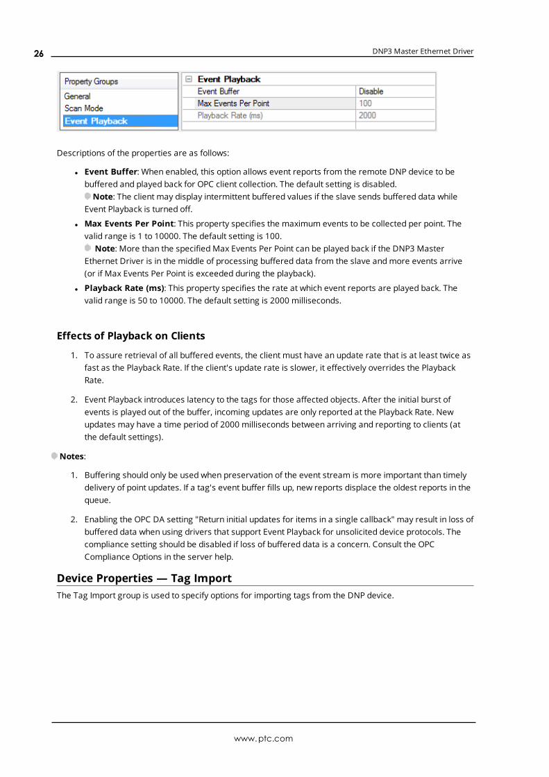
Descriptions of the properties are as follows:
l Event Buffer: When enabled, this option allows event reports from the remote DNP device to bebuffered and played back for OPC client collection. The default setting is disabled.Note: The client may display intermittent buffered values if the slave sends buffered data while
Event Playback is turned off.
l Max Events Per Point: This property specifies the maximum events to be collected per point. Thevalid range is 1 to 10000. The default setting is 100.
Note: More than the specified Max Events Per Point can be played back if the DNP3 MasterEthernet Driver is in the middle of processing buffered data from the slave andmore events arrive(or if Max Events Per Point is exceeded during the playback).
l Playback Rate (ms): This property specifies the rate at which event reports are played back. Thevalid range is 50 to 10000. The default setting is 2000 milliseconds.
Effects of Playback on Clients
1. To assure retrieval of all buffered events, the client must have an update rate that is at least twice asfast as the Playback Rate. If the client's update rate is slower, it effectively overrides the PlaybackRate.
2. Event Playback introduces latency to the tags for those affected objects. After the initial burst ofevents is played out of the buffer, incoming updates are only reported at the Playback Rate. Newupdates may have a time period of 2000 milliseconds between arriving and reporting to clients (atthe default settings).
Notes:
1. Buffering should only be used when preservation of the event stream is more important than timelydelivery of point updates. If a tag's event buffer fills up, new reports displace the oldest reports in thequeue.
2. Enabling the OPC DA setting "Return initial updates for items in a single callback" may result in loss ofbuffered data when using drivers that support Event Playback for unsolicited device protocols. Thecompliance setting should be disabled if loss of buffered data is a concern. Consult the OPCCompliance Options in the server help.
Device Properties — Tag ImportThe Tag Import group is used to specify options for importing tags from the DNP device.
www.ptc.com
26
DNP3 Master Ethernet Driver
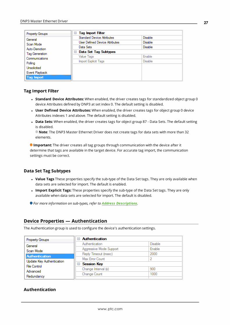
Tag Import Filter
l Standard Device Attributes:When enabled, the driver creates tags for standardized object group 0device Attributes defined by DNP3 at set index 0. The default setting is disabled.
l User Defined Device Attributes:When enabled, the driver creates tags for object group 0 deviceAttributes indexes 1 and above. The default setting is disabled.
l Data Sets:When enabled, the driver creates tags for object group 87 - Data Sets. The default settingis disabled.Note: The DNP3 Master Ethernet Driver does not create tags for data sets with more than 32
elements.
Important: The driver creates all tag groups through communication with the device after itdetermine that tags are available in the target device. For accurate tag import, the communicationsettings must be correct.
Data Set Tag Subtypes
l Value Tags These properties specify the sub-type of the Data Set tags. They are only available whendata sets are selected for import. The default is enabled.
l Import Explicit Tags: These properties specify the sub-type of the Data Set tags. They are onlyavailable when data sets are selected for import. The default is disabled.
For more information on sub-types, refer to Address Descriptions.
Device Properties — AuthenticationThe Authentication group is used to configure the device's authentication settings.
Authentication
www.ptc.com
27

DNP3 Master Ethernet Driver
l Authentication:When enabled, this property enables authentication. If the device requiresauthentication, the master needs to configure it as well. The default setting is disabled.Note: A tag import is performed when this property changes. This ensures that the authentication
object internal statistics tags are automatically generated when authentication is enabled. Thesetags are pre-defined, andmay be imported without communication with the device. Whenauthentication is disabled, a tag import is performed to remove the authentication object internalStatistics tags. When a tag import is in progress, the properties on this page is disabled. For moreinformation, refer to Tag Import.
l Aggressive Mode Support: Enable, to reduce traffic by not requiring a critical request "challengeand reply" after at least one "challenge and reply" was successful during the session key changeinterval. The default setting is enabled.
l Reply Timeout (ms): This property specifies how long the device waits for an authentication reply.The valid range is 0 to 300000 milliseconds. The default setting is 2000 milliseconds.
l Max. Error Count: This property specifies the number of error messages sent before error messagetransmission is disabled. It is also used to limit the number of authentication attempts when there isno reply from the slave. With proper timeout settings, the maximum number of authentication retriesper response timeout are Max. Error Count + 2. The valid range is 0 to 10. The default setting is 2.
Session Key
l Change Interval (s): This property specifies the session key change timeout to be used by themaster to determine when to change session keys. When a value of 0 is entered, Session Key ChangeCount is used instead. The valid range is 0 to 7200 seconds. The default setting is 900 seconds.
l Change Count: This property specifies the number of transmitted authenticationmessages at whichthe master changes session keys. The messages may have been transmitted in either direction. Thevalid range is 0 to 65535. The default setting is 1000.
Note: The DNP3 Master Ethernet Driver automatically matches the HMAC algorithm as configured inthe slave.
Device Properties — Update Key AuthenticationThe Update Key Authentication group is used to configure the device's authentication settings.
Current User
www.ptc.com
28
DNP3 Master Ethernet Driver
l Current User Number: Specify howmany users can retrieve the Update Key during authentication.The default setting is 1.
Update Key nThis section displays an array of 10 users, each with a unique 16 hexadecimal byte Update Key. The sameUser Number-Update Key combinationmust be configured in the device.
l User Number: This property modifies the current User Number. The valid range for User Number is0 to 65535. The default setting for the first row of User Numbers is 1. All others are 0.
l Update Key:Modify the existing Update Key in this field. Update Keys can be entered either as 32characters (such as "493B56AF89120C0429767DB301C63CA8") or as 16 sets of 2 characters thatare separated by spaces (such as "49 3B 56 AF 89 12 0C 04 29 76 7D B3 01 C6 3C A8").
Tip: Copy and paste functionality works properly for these fields using the Windows clipboard .
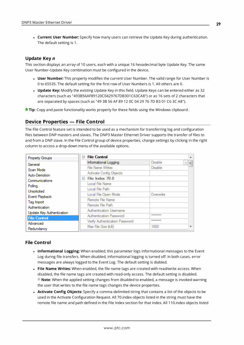
Device Properties — File ControlThe File Control feature set is intended to be used as a mechanism for transferring log and configurationfiles between DNPmasters and slaves. The DNP3 Master Ethernet Driver supports the transfer of files toand from a DNP slave. In the File Control group of device properties, change settings by clicking in the rightcolumn to access a drop-downmenu of the available options.
File Control
l Informational Logging:When enabled, this parameter logs informational messages to the EventLog during file transfers. When disabled, informational logging is turned off. In both cases, errormessages are always logged to the Event Log. The default setting is diabled.
l File Name Writes:When enabled, the file name tags are created with read/write access. Whendisabled, the file name tags are created with read-only access. The default setting is disabled.Note: When the applied setting changes from disabled to enabled, a message is invoked warning
the user that writes to the file name tags changes the device properties.
l Activate Config Objects: Specify a comma-delimited string that contains a list of the objects to beused in the Activate Configuration Request. All 70.index objects listed in the string must have theremote file name and path defined in the File Index section for that index. All 110.index objects listed
www.ptc.com
29
DNP3 Master Ethernet Driver
must have a tag defined for that data point. For example, the format of this list would be 70.0, 70.1,110.5. The maximum number of characters allowed for this string is 256.
File Index 70.nThe following local and remote path and file settings, file authentication, andmaximum size are for the DNPMaster local file index n.
l Local File Name: Specify the name of the file located on the master. It can include the entire path,part of the path, or only the file name. If a local path is defined, the local file identifier is defined byeither <local path>\<local file name> or <local path>/<local file name>. The file name property isexposed to the client in a tag. If the File Name Writes property is enabled, the client can change thefile name as needed by writing to the tag. The maximum number of characters for the file identifier is256.
l Local File Path: Specify the local path of the file. When users double-click in the right column of thisproperty, a file path browser is invoked. If the Local File Name property contains the entire fileidentifier, the path property should remain empty. For security, the path property is not exposed tothe client in a tag. A non-empty path precedes a backslash (or forward slash) and the local file nameto identify the local file. The maximum number of characters for the file identifier is 256.Note: The Local File Path and Name must form a valid UNC path (which cannot contain the
characters |?"*:<>). For security purposes, the parent directory (denoted by '..') is not permitted.Furthermore, the current user must have Read/Write privileges to the Local File Identifier.
l Local File Open Mode:WhenOverwrite is selected, the local file is overwritten during file transfers.When Append is selected, the incoming file data is appended to an existing file. The default setting isOverwrite.
l Remote File Name: This is the definition of the DNP slave remote file. The Remote File Identifier isrestricted in length to 256 characters. Because the server cannot verify that the file name and pathare valid, users must make sure to specify the path correctly to avoid unintended file transfers. Forexample, users that set the Remote File Identifier to a folder/directory on the DNP slave may find thatthe transfer completes successfully, but that the file cannot be used by the DNPMaster. Remote FileName: Specify the name of the file located on the slave. This entry can include the entire path, part ofthe path, or only the file name. If a remote path is defined, then the remote file identifier is defined byeither <remote path>\<remote file name> or <remote path>/<remote file name>. The file nameproperty is exposed to the client in a tag. If the File Name Writes property is enabled, then the clientcan change the file name as needed by writing to the tag. The maximum number of characters forthe file identifier is 256.
l Remote File Path: Specify the path of the file located on the slave. If the Remote File Nameproperty contains the entire file identifier, the path property should remain empty. For security, thepath property is not exposed to the client in a tag. A non-empty path precedes a backslash (orforward slash) and the remote file name to identify the remote file. The maximum number ofcharacters for the file identifier is 256.
l Authentication Username: Specify the username required by the device to authenticate the file.The maximum number of characters is 32.
l Authentication Password: Specify the password required by the device to authenticate the file. Theencrypted password is case-sensitive, and is not displayed. The maximum number of characters is32.
l Verify Authentication Password: This property verifies the password entered in the parameterabove. The encrypted verification password is case-sensitive, and is not displayed. The maximumnumber of characters is 32.
www.ptc.com
30

DNP3 Master Ethernet Driver
l Max File Size (kB): Specify the maximum file size in kilobytes that are allowed in file transfers. Thevalid range is 100 to 65535 kilobytes. The default setting is 1000 kilobytes.
Tip: When property changes are made and applied, a tag import is performed. At that time, a tag grouptitled "File Control" is created automatically. Four tags for each of the 0-9 file indexes that have non-emptyfile names or path names are also created. The format of the tags is 70.<index>.Upload,70.<index>.Download, 70.<index>.LocalFileName, and 70.<index>.RemoteFileName. These tags are pre-defined, andmay be imported without communication with the device. When a tag import is in progress, theproperties on this page are disabled. For more information, refer to Tag Import.
Device Properties — AdvancedThe Advanced group is used to specify the operate mode, whether to perform a feedback poll after a write,how to display the DNP .Timestamp, whether to exchange data sets on restart, and whether to loginformational messages to the Event Log when device Restart or Need Time IIN bits are set.
Operate Mode: This property determines whether the writable I/O points (object group 10 - Binary Outputsand object group 40 - Analog Outputs) use the Direct Operate or Select then Operate sequence. The defaultselection is Direct Operate.Note: Individual tags' write behavior can override this setting by writing a Boolean True to the output's
corresponding .DO or .SO sub-type tags. For more information, refer to DNP DO and SO sub-types.
Feedback Poll After Operate: When enabled, this property enables a feedback poll to occur after anoperate. The default setting is enabled.
Timestamp to Local Time: When enabled, this property converts the UTC timestamp to local time. It isdisplayed in .Timestamp tags. The default setting is disabled.
Ignore Remote Force Flag: If the DNP Remote Force flag is set and this property is disabled, the quality ofthe corresponding .Value and .Explicit tags is bad. If the DNP Remote Force flag is set at the slave end andthis property is enabled, the quality of the corresponding .Value and .Explicit tags remain good. The defaultsetting is disabled.
Ignore Local Force Flag: If the DNP Local Force flag is set and this property is disabled, the quality of thecorresponding .Value and .Explicit tags are bad. If the DNP Local Force flag is set at the slave end and thisparameter is enabled, the quality of the corresponding .Value and .Explicit tags remain good. The defaultsetting is disabled.
www.ptc.com
31

DNP3 Master Ethernet Driver
Exchange Data Sets:When enabled, this property ensures that the data set prototypes and descriptors areexchanged with the slave whenever the master or slave restarts. When disabled, the initial exchange of datasets does not take place. If a Data Set tag needs to be updated, the data set prototype and descriptors mustbe exchanged before requesting the update. If the master restarts and does not exchange data sets, anydata set events that occurred before the master restarted are lost: the master has no knowledge of the datasets. The default setting is disabled.
Device Restart IIN Logging:When enabled, this property logs informational messages to the Event Logwhen a response from the slave has the device Restart IIN 1.7 bit set. When disabled, informational loggingis turned off. The default setting is disabled.
Need Time IIN Logging:When enabled, this property logs informational messages to the Event Log when aresponse from the slave has the Need Time IIN 1.4 bit set. When disabled, informational logging is turnedoff. The default setting is disabled.For more information on DNP flag bytes, refer to "DNP Object Flag Definitions" located in object group 1, 3, 10,
20, 21, 30, and 40.
Device Properties — Redundancy
Redundancy is available with the Media-Level Redundancy Plug-In.Consult the website, a sales representative, or the user manual for more information.
www.ptc.com
32

DNP3 Master Ethernet Driver
Data Types Description
Data Type Description
Boolean Single bit
Word
Unsigned 16-bit value
bit 0 is the low bitbit 15 is the high bit
Short
Signed 16-bit value
bit 0 is the low bitbit 14 is the high bitbit 15 is the sign bit
DWord
Unsigned 32-bit value
bit 0 is the low bitbit 31 is the high bit
Long
Signed 32-bit value
bit 0 is the low bitbit 30 is the high bitbit 31 is the sign bit
Float 32-bit floating-point value
Double 64-bit floating-point value
String Null-terminated ASCII string
www.ptc.com
33

DNP3 Master Ethernet Driver
Address DescriptionsTag AddressingTag addressing is of the form OBJ.VAR.IDX.SUB (ObjectGroup.Variation.Index.Sub-Type), where:
l OBJ: The data object group.
l VAR: The variation requested for the tag equates to data type. Strings do not have a variationcomponent.
Note: The variation is only applicable to .Value and .Explicit sub-types. For .Value tags, no request issent to the slave. All variations defined for .Value tags in the master display the value in the slave'sdefault event variation. For .Explicit tags, the variation is used in the request to the slave. If therequest is for variation 0, the slave returns the value in its default static variation. All other variationsfor .Explicit tags are specifically requested from the slave.
l IDX: The specific data object in a given group. For example, IDX 4 is the 5th binary input. Indexes startwith 0 for each object group with multiple points. Some objects, such as Objects 50 and 60, do nothave an index component.
l SUB: The specific attribute of the point.
See Also: Other Object Groups
Sub-TypesValues reported to the server from the slave device are in the slave device's default variation (which maydiffer from the server default variation) and are obtained through report by exception. Certain object groupvariations in the DNP3 protocol return multiple data items. For example, object group 20.1 asks for ananalog input point's 32-bit value as well as a Flag byte. Many event object group variations also return thetime of occurrence: because the OPC interface does not handle complex data types, the value, flags, andtimestamp data are not available in a single tag. The OPC server must retrieve the various parts of thecombined report in separate tags.
l For the .SUB value attribute, the data type is designated by the variation (.VAR). If the variation is .0,the .SUB value attribute has the same data type as the default variation.
l For the .SUB flags attributes contained within the flags attribute, the data type is always Boolean.They are unaffected by the variation.
l For the .SUB flags attribute, the data type is always byte. It is unaffected by the variation.
l The .SUB timestamp attribute is always Date. It is unaffected by the variation.
Sub-Type Description
Value The current value of the point. The data type returned from the slave dependson the default event variation and the default static variation configured in theslave for the point. The data type exposed to the client depends on thevariation part of the tag address.
Explicit
The current value of the point. The data type varies as determined by theselected variation. Reading a tag with the Explicit sub-type causes the driver toinitiate a DNP Read transaction.
DNP is usually used in a report-by-exceptionmodel, where the DNP slavedevice responds to an Event Poll with the point data that has changed since thelast report. Some DNP slave devices may have I/O points that are not
www.ptc.com
34

DNP3 Master Ethernet Driver
Sub-Type Description
configured to answer to Event or Integrity polls. These points require specialhandling via the .Explicit sub-type. The .Explicit sub-type triggers a DNP readtransaction for every tag update, which may cause traffic on the DNP bus. Tagsusing the .Explicit sub-type must use a suitable update rate. Rates of 1000 msor longer are recommended, as is limiting the use of .Explicit tags to onlywhere required. It is the user's responsibility to configure .Explicit tagsappropriately.
Note: To reduce traffic, Explicit reads of the same object group and variationare blocked together to be read 64 at a time. If any tag in the block fails, thewhole block fails.
Timestamp
The date and time of the last update received from the slave (if an event hasoccurred and the time of occurrence was returned).
A successful write to a .Value or .Explicit tag causes its corresponding.Timestamp tag quality to be bad. The timestamp of the .Timestamp tag is thenthe timestamp of the update from the write. The next time a DNP timestamp isreceived, the quality of the .Timestamp tag changes to good and its timestampdisplays the DNP timestamp.
Note: The timestamp of the .Value item is only updated if its value haschanged since the last update. To find the current DNP timestamp value forthe point, use the DNP .Timestamp tag.
Online Boolean: True if the slave is online.
Restart Boolean: True if the slave has been restarted.
Lost Boolean: True if communications with this point were lost.
RemoteForceBoolean: True if the point value is forced to its current state at a device otherthan the end device.
LocalForceBoolean: True if the point value is forced to its current state at the end device.
Note: Local force is not yet implemented.
Chatter Boolean: True if the slave's chatter filter is activated and applying correction.
Reference CheckBoolean: True if the reference signal used to digitize the analog input is notstable and the resulting digitized value may not be correct.
Over-rangeBoolean: True if the digitized signal or calculation has exceeded its range. Theactual value field can be ignored as its value is not defined.
DO*Boolean: True if a writable point is set to Direct Operate mode. Writing to a tagof this sub-type overrides the global Operate Mode setting. For moreinformation, refer to Operate Mode.
SO*Boolean: True if a writable point is set to Select then Operate mode. Writing toa tag of this sub-type overrides the global Operate Mode setting. For moreinformation, refer to Operate Mode.
Flags The full set of transaction flags (0 through 7) for the specified DNP point.
OperateThis limited functionality is only retained to support older projects. New
www.ptc.com
35

DNP3 Master Ethernet Driver
Sub-Type Description
projects should use the enhanced Operate commands shown below.**
The user specifies a crafted value to write. The .Operate sub-type isimplemented as a DWord, but currently only the lowest 8 bits are significant.Bits 0-3 form a command number. Allowable values are currently 0-4. Valuesoutside this range result in a failed write. The commands are as follows:
0 - No operation1 - Pulse on2 - Pulse off3 - Latch on (same as writing a 1 to 10.x.x.Value)4 - Latch off (same as writing a 0 to 10.x.x.Value.
Bit 4 is the Queue commandmodifier.Bit 5 is the Clear commandmodifier.
Bits 6 & 7 form a Trip-Close command pair. Allowable values are currently 0-2.Values outside this range result in a failed write.
Bit 6 is the Paired Close commandmodifier.Bit 7 is the Paired Trip commandmodifier.
The allowable commands are as follows:
0 - Nul1 - Close2 - Trip
Enhanced OperateControls
These expanded Operate sub-types allow a user to completely controlcommands sent to a Control Relay Output Block.**
Operate.OpType
This Byte contains the specific operation type to perform. The commands areas follows:
0 - No operation1 - Pulse on2 - Pulse off3 - Latch on (same as writing a 1 to 10.x.x.Value)4 - Latch off (same as writing a 0 to 10.x.x.Value)
Operate.TripCloseCode
This Byte contains the Trip-Close code to apply to the operation. Thecommands are as follows:
0 - No operation1 - Close2 - Trip
Operate.Clear This Boolean adds the 'Clear' attribute to the command.
Operate.OnTime This DWord specifies the on-time in milliseconds for the command.
Operate.OffTime This DWord specifies the off-time in milliseconds for the command.
Operate.FeedbackDelay This DWord specifies the time in milliseconds before a feedback poll is
www.ptc.com
36

DNP3 Master Ethernet Driver
Sub-Type Description
performed after the command completes.
Operate.SetAfter all of the parameters above have been written, writing True to thisBoolean initiates the command.
*Direct Operate (DO) and Select-then-Operate (SO) sub-types apply only to object groups 10 and 40. DO andSO are not allowed for other object groups.** See Also: Object 10 - Binary Outputs.
Object Group 0 - Device AttributesThese tags are only read explicitly once after start up. If the device does not support object group 0 (or thespecific variation), the tag quality is bad; as such, explicit reads of this tag do not resume until the master orslave restarts.
AttributesThe default data type is shown in bold.
OBJ.VAR.IDXAttributes*
.SUBAttribute
Data Type Access
0.{1-253}.{0-65535} ValueByte, Char, Double, DWord, Float, Long, Short,String**, Word
Read/Write
*The IDX attribute indicates the particular set of device attributes that are defined in the device. The set ofstandardized device attributes defined by DNP3 are accessible at set index 0; indexes 1 and above areavailable for vendor-specific attributes.
**Device attribute strings have a maximum length of 210 characters.
Note: Flags do not apply.
VariationsVariations for object group 0 do not equate to a specific data type. A variation is a specific element for a setof device attributes. If the tag is configured by the user, the variation's data type must match the data typethat is configured in the slave.
Although the DNP protocol allows requests for object group 0, variations 254 and 255, the DNP3 MasterEthernet Driver does not allow tags to be created with those variations. The responses to each of thoserequests may be too large for a tag value.
Number Description
254This attribute is used as shorthand to request that a device return all of its attributes in asingle response.
255This special attribute is used to retrieve a list of all the device attribute variation numbers (inaddition to their properties) that are supported by the device at a specified index.
Note: Tags with other device attribute variations can both be manually created and automaticallygenerated through the Tag Import settings in device Properties. During tag import, the driver issuesrequests for group 0 Variation 254 and group 0 Variation 255 to gather information from the device and to
www.ptc.com
37

DNP3 Master Ethernet Driver
create only those device attribute tags as defined in the responses. For more information, refer to TagImport.
ExamplesTagAddress
Definition Description
0.211.0.Value
Displays thestandard DNP deviceAttribute Number ofAnalog Outputs.
If a value for this tag has not been received from the device, anexplicit request is sent. Once the point has been initialized, the tagreceives its updates from the data store. A second explicit requestis only issued if the slave or master restarts.
If the response to the initial request indicates that the device doesnot support the variation 211 of set 0, then no other request isissued and tag quality is bad. The user must configure the tag'sdata type to match the data type as configured by the slave.
0.250.0.Value
Displays thestandard DNP deviceAttributeManufacturer'sproduct name andmodel.
If a value for this tag has not been received from the device, anexplicit request is sent. Once the point has been initialized, the tagreceives its updates from the data store. A second explicit requestis only issued if the slave or master restarts.
If the response to the initial request indicates that the device doesnot support variation 250 of set 0, no other request is issued andthe tag quality is bad. The user must configure the tag's data typeto match the data type as configured by the slave.
0.211.1.ValueDisplays the customdevice attribute set 1variation 211 value.
If a value for this tag has not been received from the device, anexplicit request is sent. Once the point has been initialized, the tagreceives its updates from the data store. A second explicit requestis only issued if the slave or master restarts.
If the response to the initial request indicates that the device doesnot support variation 211 of set 1, then no other request is issuedand the tag quality is bad. The user must configure the tag's datatype to match the data type as configured by the slave.
Object Group 1- Binary InputsThe status for each point in an object group is retained on each transaction; all flags are reported in theirsub-type tags. The corresponding event object may also return Time of Occurrence.
Note: Object group 1 - Binary Input State is reflected in object group 2 - Binary Input Change Event. Formore information, refer toOther Object Groups.
AttributesThe default data type is shown in bold.
OBJ.VAR.IDXAttributes
.SUB AttributeDataType
Access
1.{0,1,2}.{0-65535}Chatter, LocalForce, Lost, Online, RemoteForce,Restart
BooleanReadOnly
www.ptc.com
38

DNP3 Master Ethernet Driver
OBJ.VAR.IDXAttributes
.SUB AttributeDataType
Access
1.{0,1,2}.{0-65535} Flags ByteReadOnly
1.{0,1,2).{0-65535} TimeStamp DateReadOnly
1.0.{0-65535} Value, Explicit BooleanReadOnly
1.1.{0-65535} Value, Explicit BooleanReadOnly
1.2.{0-65535} Value, Explicit ByteReadOnly
VariationsNumber Description
0 Variation determined by slave device
1 Packed format
2 With Flags
DNP Object Flag DefinitionsIf the device returns an exception bit set, the quality of the .Value or .Explicit tag is bad. The followingavailable bits are exception bits, excluding Online and State. Descriptions are as follows:
l 0: Online
l 1: Restart
l 2: Communications Lost
l 3: Remote Force
l 4: Local Force
l 5: Chatter
l 6: Reserved
l 7: State - Status of input.
ExamplesTag Address Definition Description
1.0.0.Value*Value of point 0as a Boolean
This tag is updated from the data store that is populated viaresponses to integrity and event polls. An explicit request is notsent to the device. Although the slave could return variation 1 or 2(depending on its object group 2 default event variation), this tagdisplays the state of the binary input point 0 without the flags.
1.0.5.ExplicitValue of point 5as a Boolean
An explicit request is sent to the device to get the value for this tag.Other object 1 variation 0 Explicit tags are blocked with this tag inone request. Although the slave could return variation 1 or 2(depending on its default static variation), this tag displays thestate of the binary input point 5 without the flags.
1.1.10.ExplicitValue of point10 as a Boolean
An explicit request is sent to the device to get the value for this tag.Other object 1 variation 1 explicit tags are blocked with this tag in
www.ptc.com
39
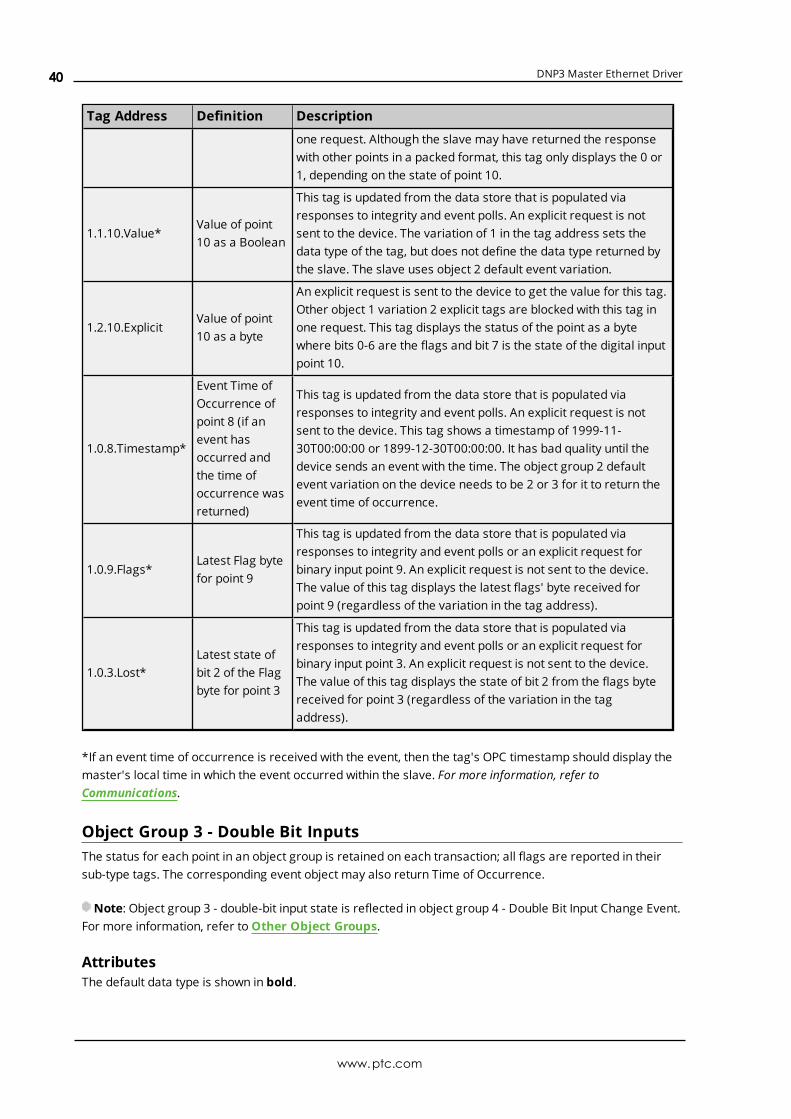
DNP3 Master Ethernet Driver
Tag Address Definition Description
one request. Although the slave may have returned the responsewith other points in a packed format, this tag only displays the 0 or1, depending on the state of point 10.
1.1.10.Value*Value of point10 as a Boolean
This tag is updated from the data store that is populated viaresponses to integrity and event polls. An explicit request is notsent to the device. The variation of 1 in the tag address sets thedata type of the tag, but does not define the data type returned bythe slave. The slave uses object 2 default event variation.
1.2.10.ExplicitValue of point10 as a byte
An explicit request is sent to the device to get the value for this tag.Other object 1 variation 2 explicit tags are blocked with this tag inone request. This tag displays the status of the point as a bytewhere bits 0-6 are the flags and bit 7 is the state of the digital inputpoint 10.
1.0.8.Timestamp*
Event Time ofOccurrence ofpoint 8 (if anevent hasoccurred andthe time ofoccurrence wasreturned)
This tag is updated from the data store that is populated viaresponses to integrity and event polls. An explicit request is notsent to the device. This tag shows a timestamp of 1999-11-30T00:00:00 or 1899-12-30T00:00:00. It has bad quality until thedevice sends an event with the time. The object group 2 defaultevent variation on the device needs to be 2 or 3 for it to return theevent time of occurrence.
1.0.9.Flags*Latest Flag bytefor point 9
This tag is updated from the data store that is populated viaresponses to integrity and event polls or an explicit request forbinary input point 9. An explicit request is not sent to the device.The value of this tag displays the latest flags' byte received forpoint 9 (regardless of the variation in the tag address).
1.0.3.Lost*Latest state ofbit 2 of the Flagbyte for point 3
This tag is updated from the data store that is populated viaresponses to integrity and event polls or an explicit request forbinary input point 3. An explicit request is not sent to the device.The value of this tag displays the state of bit 2 from the flags bytereceived for point 3 (regardless of the variation in the tagaddress).
*If an event time of occurrence is received with the event, then the tag's OPC timestamp should display themaster's local time in which the event occurred within the slave. For more information, refer toCommunications.
Object Group 3 - Double Bit InputsThe status for each point in an object group is retained on each transaction; all flags are reported in theirsub-type tags. The corresponding event object may also return Time of Occurrence.
Note: Object group 3 - double-bit input state is reflected in object group 4 - Double Bit Input Change Event.For more information, refer toOther Object Groups.
AttributesThe default data type is shown in bold.
www.ptc.com
40

DNP3 Master Ethernet Driver
OBJ.VAR.IDXAttributes
.SUB AttributeDataType
Access
3.{0,1,2}.{0-65535}Chatter, LocalForce, Lost, Online, RemoteForce,Restart
BooleanReadOnly
3.{0,1,2}.{0-65535} Flags ByteReadOnly
3.{0,1,2}.{0-65535} TimeStamp DateReadOnly
3.0.{0-65535} Value, Explicit ByteReadOnly
3.1.{0-65535} Value, Explicit ByteReadOnly
3.2.{0-65535} Value, Explicit Byte*ReadOnly
*The extra bits are used to provide Flags.
VariationsNumber Description Bits
0Variation determined by slavedevice
N/A
1 Packed formatBits 0 and 1: 0 is Intermediate, 1 is OFF, 2 is ON, 3 isIndeterminate.
2 With FlagsBits 6 and 7: 0 is Intermediate, 1 is OFF, 2 is ON, 3 isIndeterminate.
DNP Object Flag DefinitionsIf the device returns an exception bit set, the quality of the .Value or .Explicit tag is bad. The followingavailable bits are exception bits, excluding Online and State. Descriptions are as follows:
l 0: Online
l 1: Restart
l 2: Communications Lost
l 3: Remote Force
l 4: Local Force
l 5: Chatter
l 6: State - Status of input.
l 7: State - Status of input.
ExamplesTag Address Definition Description
3.0.0.Value*Value of point 0as a byte
This tag is updated from the data store that is populated viaresponses to integrity and event polls. No explicit request is sentto the device. Although the slave could return variation 1 or 2(depending on its object group 4 default event variation), this tagdisplays the state of the double-bit binary input point 0 without the
www.ptc.com
41

DNP3 Master Ethernet Driver
Tag Address Definition Description
flags.
3.0.5.ExplicitValue of point 5as a byte
An explicit request is sent to the device to get the value for thistag. Other object 3 variation 0 Explicit tags are blocked with thistag in one request. Although the slave could return variation 1 or 2(depending on its default static variation), this tag displays thestate of the double-bit binary input point 5 without the flags.
3.1.10.ExplicitValue of point10 as a byte
An explicit request is sent to the device to get the value for thistag. Other object 3 variation 1 Explicit tags are blocked with thistag in one request. Although the slave returned the response in apacked format, possibly with other points, this tag only shows 0(intermediate), 1 (Off), 2 (On), or 3 (indeterminate); depending onthe state of point 10.
3.1.10.Value*Value of point10 as a byte
This tag is updated from the data store that is populated viaresponses to integrity and event polls. No explicit request is sentto the device. The variation of 1 in the tag address sets the datatype of the tag, but does not define the data type returned by theslave (which uses its object 4 default event variation).
3.2.10.ExplicitValue of point10 as a byte
An explicit request is sent to the device to get the value for thistag. Other object 3 variation 2 Explicit tags are blocked with thistag in one request. This tag displays the status of the point as abyte where bits 0-5 are the flags and bits 6 & 7 are the state of thedigital input point 10.
3.0.8.Timestamp*
Event Time ofOccurrence ofpoint 8 (if anevent hasoccurred andthe time ofoccurrence wasreturned).
This tag is updated from the data store that is populated viaresponses to integrity and event polls. No explicit request is sentto the device. This tag shows a timestamp of 1999-11-30T00:00:00or 1899-12-30T00:00:00. It has bad quality until the device sendsan event with the time. The object group 4 default event variationon the device needs to be 2 or 3 for it to return the event time ofoccurrence.
3.0.9.Flags*Latest Flag bytefor point 9
This tag is updated from the data store that is populated viaresponses to integrity and event polls or an explicit request forbinary input point 9. No explicit request is sent to the device. Thevalue of this tag displays the latest flags' byte received for point 9regardless of the variation in the tag address.
3.0.3.Lost*
Latest state ofthe bit 2 of theFlag Byte forpoint 3
This tag is updated from the data store that is populated viaresponses to integrity and event polls or an explicit request forbinary input point 3. No explicit request is sent to the device. Thevalue of this tag displays the state of bit 2 from the flags bytereceived for point 3 regardless of the variation in the tag address.
*If an event time of occurrence is received with the event, then the tag's OPC timestamp should display themaster's local time in which the event occurred within the slave. For more information, refer toCommunications.
www.ptc.com
42

DNP3 Master Ethernet Driver
Object Group 10 - Binary OutputsThe status for each point in an object group is retained on each transaction; all flags are reported in theirsub-type tags. The corresponding event object may also return Time of Occurrence.
Note: Object group 10 - Binary Output State is reflected in object group 11 - Binary Output Change Event,object group 12 - Control Relay Output Block, and object group 13 - Binary Output Command Event. For moreinformation, refer toOther Object Groups.
See Also: Object Group 12 - Binary Output Commands
AttributesThe default data type is shown in bold.
OBJ.VAR.IDXAttributes
.SUB AttributeDataType
Access
10.{0,1,2}.{0-65535} LocalForce, Lost, Online, RemoteForce, Restart Boolean Read Only
10.{0,1,2}.{0-65535} DO, SO Boolean Read/Write
10.{0,1,2}.{0-65535} Operate.Set, Operate.Clear Boolean Read/Write
10.{0,1,2}.{0-65535} Operate.OpType, Operate.TripCloseCode Byte Read/Write
10.{0,1,2}.{0-65535}Operate.OnTime, Operate.OffTime,Operate.FeedbackDelay
DWord Read/Write
10.{0,1,2}.{0-65535} Flags Byte Read Only
10.{0,1,2}.{0-65535} TimeStamp Date Read Only
10.0.{0-65535} Value, Explicit Boolean Read/Write
10.1.{0-65535} Value, Explicit Boolean Read/Write
10.2.{0-65535} Value, Explicit Byte* Read Only
*The extra bits are used to provide Flags.
VariationsNumber Description
0 Variation determined by slave device.
1 Packed format.
2 Status with Flags.
DNP Object Flag DefinitionsIf the device returns an exception bit set, the quality of the .Value or .Explicit tag is bad. The followingavailable bits are exception bits, excluding Online and State. Descriptions are as follows:
l 0: Online
l 1: Restart
l 2: Communications Lost
l 3: Remote Force
l 4: Local Force
l 5: Reserved
www.ptc.com
43

DNP3 Master Ethernet Driver
l 6: Reserved
l 7: State - Status of input.
Binary Output ExamplesTag Address Definition Description
10.0.0.Value*Value of point 0as a Boolean
This tag is updated from the data store that is populated viaresponses to integrity and event polls. No explicit request aresent to the device. Although the slave could return variation 1 or 2(depending on its object group 11 default event variation), this tagdisplays the state of the binary output point 0 without the flags.
10.0.5.ExplicitValue of point 5as a Boolean
An explicit request is sent to the device to get the value for thistag. Other object 10 variation 0 Explicit tags are blocked with thistag in one request. Although the slave could return variation 1 or2 (depending on its default static variation), this tag displays thestate of the binary output point 5 without the flags.
10.1.10.ExplicitValue of point10 as a Boolean
An explicit request is sent to the device to get the value for thistag. Other object 10 variation 1 Explicit tags are blocked with thistag in one request. Although the slave may return the responsewith other points in a packed format, this tag only shows the 0 or1 (depending on the state of point 10).
10.1.10.Value*Value of point10 as a Boolean
This tag is updated from the data store that is populated viaresponses to integrity and event polls. No explicit request is sentto the device. The variation of 1 in the tag address sets the datatype of the tag. It does not define the data type returned by theslave, which uses its object group 11 default event variation.
10.2.10.ExplicitValue of point10 as a byte
An explicit request is sent to the device to get the value for thistag. Other object 10 variation 2 Explicit tags are blocked with thistag in one request. This tag displays the status of the point as abyte, where bits 0-6 are the flags and bit 7 is the state of thedigital output point 10.
10.0.8.Timestamp*
Event Time ofOccurrence ofpoint 8 (if anevent hasoccurred andthe time ofoccurrence wasreturned)
This tag is updated from the data store that is populated viaresponses to integrity and event polls. No explicit request is sentto the device. This tag shows a timestamp of 1999-11-30T00:00:00 or 1899-12-30T00:00:00. It has bad quality until thedevice sends an event with the time. The object group 11 defaultevent variation on the device needs to be 2 for it to return theevent time of occurrence.
10.0.9.Flags*Latest Flag bytefor point 9
This tag is updated from the data store that is populated viaresponses to integrity and event polls or an explicit request forbinary output point 9. No explicit request is sent to the device. Thevalue of this tag displays the latest flags' byte received for point 9(regardless of the variation in the tag address).
10.0.3.Lost*Latest state ofbit 2 of the Flagbyte for point 3
This tag is updated from the data store that is populated viaresponses to integrity and event polls or an explicit request forbinary output point 3. No explicit request is sent to the device. Thevalue of this tag displays the state of bit 2 from the flags' bytereceived for point 3 (regardless of the variation in the tag
www.ptc.com
44
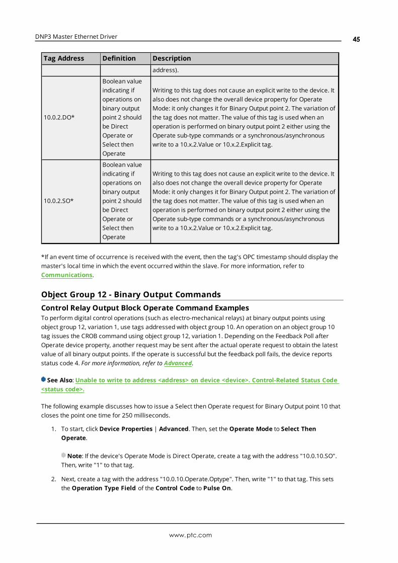
DNP3 Master Ethernet Driver
Tag Address Definition Description
address).
10.0.2.DO*
Boolean valueindicating ifoperations onbinary outputpoint 2 shouldbe DirectOperate orSelect thenOperate
Writing to this tag does not cause an explicit write to the device. Italso does not change the overall device property for OperateMode: it only changes it for Binary Output point 2. The variation ofthe tag does not matter. The value of this tag is used when anoperation is performed on binary output point 2 either using theOperate sub-type commands or a synchronous/asynchronouswrite to a 10.x.2.Value or 10.x.2.Explicit tag.
10.0.2.SO*
Boolean valueindicating ifoperations onbinary outputpoint 2 shouldbe DirectOperate orSelect thenOperate
Writing to this tag does not cause an explicit write to the device. Italso does not change the overall device property for OperateMode: it only changes it for Binary Output point 2. The variation ofthe tag does not matter. The value of this tag is used when anoperation is performed on binary output point 2 either using theOperate sub-type commands or a synchronous/asynchronouswrite to a 10.x.2.Value or 10.x.2.Explicit tag.
*If an event time of occurrence is received with the event, then the tag's OPC timestamp should display themaster's local time in which the event occurred within the slave. For more information, refer toCommunications.
Object Group 12 - Binary Output CommandsControl Relay Output Block Operate Command ExamplesTo perform digital control operations (such as electro-mechanical relays) at binary output points usingobject group 12, variation 1, use tags addressed with object group 10. An operation on an object group 10tag issues the CROB command using object group 12, variation 1. Depending on the Feedback Poll afterOperate device property, another request may be sent after the actual operate request to obtain the latestvalue of all binary output points. If the operate is successful but the feedback poll fails, the device reportsstatus code 4. For more information, refer to Advanced.
See Also: Unable to write to address <address> on device <device>. Control-Related Status Code<status code>.
The following example discusses how to issue a Select then Operate request for Binary Output point 10 thatcloses the point one time for 250 milliseconds.
1. To start, click Device Properties | Advanced. Then, set the Operate Mode to Select ThenOperate.
Note: If the device's Operate Mode is Direct Operate, create a tag with the address "10.0.10.SO".Then, write "1" to that tag.
2. Next, create a tag with the address "10.0.10.Operate.Optype". Then, write "1" to that tag. This setsthe Operation Type Field of the Control Code to Pulse On.
www.ptc.com
45

DNP3 Master Ethernet Driver
3. Next, create a tag with the address "10.0.10.Operate.Tripclosecode". Then, write "1" to that tag. Thissets the Trip-Close Code Field of the Control Code to Close.
4. Next, create a tag with the address "10.0.10.Operate.Ontime". Then, write "250" to that tag. This setsthe duration (in milliseconds) in which the output drive remains active.
5. Next, create a tag with the address "10.0.10.Operate.Set". Then, write "1" to that tag. This triggersthe master to send the object group 12, variation 1 request that performs the digital controloperation.
See Also:Object Group 10 - Binary Outputs
Note: The Channel Diagnostics should display the three transactions. The master sends a request usingfunction code 0x03 to select the output point. The slave responds by echoing the request if everything isokay. The master then sends the operate request using function code 0x04. The slave responds by echoingthe request if everything is okay. The master then sends the feedback poll and the slave responds with thecurrent static value for all binary outputs.
Tag Address Definition Description
10.0.2.Operate.Clear
Value of theCROBcontrol codebit 5
This Boolean tag displays a 0 or 1, depending on the lastupdate from the client. The variation of the tag does notmatter. Writing to this tag does not cause an explicit writeto the device. It is used in building the CROB control codeto be written to the object group 12 point 2 with theOperate.Set tag.
10.0.2.Operate.OpType
Value of theCROBcontrol codebits 0-3.
This byte tag displays the operation type, depending onthe last update from the client. Operation types are asfollows:
Nul (0)Pulse_On (1)Pulse_Off (2)Latch_On (3)Latch_Off (4)
The variation of the tag does not matter. Writing to thistag does not cause an explicit write to the device. It isused in building the CROB control code that is written tothe object group 12 point 2 with the Operate.Set tag.
10.0.2.Operate.TripCloseCode
Value of theCROBcontrol codebits 6 & 7
This byte tag displays the Trip-Close field, depending onthe last update from the client.Trip-close fields are as follows:
Nul (0)Paired_Close (1)Paired_Trip (2)
The variation of the tag does not matter. Writing to thistag does not cause an explicit write to the device. It isused in building the CROB control code to be written tothe object group 12 point 2 with the Operate.Set tag.
www.ptc.com
46

DNP3 Master Ethernet Driver
Tag Address Definition Description
10.0.2.Operate.OnTime
Value inmillisecondsthat theoperation onthe binaryoutput point2 remainsactive
This DWord tag displays the on time last updated fromthe client. The variation of the tag does not matter.Writing to this tag does not cause an explicit write to thedevice. It is used in an object group 12 control operationon binary output point 2 when the Operate.Set tag istoggled to 1.
10.0.2.Operate.OffTime
Value inmillisecondsthat theoperation onthe binaryoutput point2 remainsnon-active
This DWord tag displays the off time last updated fromthe client. The variation of the tag does not matter.Writing to this tag does not cause an explicit write to thedevice. It is used in an object group 12 control operationon binary output point 2 when the Operate.Set tag istoggled to 1.
10.0.2.Operate.FeedbackDelay
Value inmillisecondsto delayafterreceivingtheresponsebeforeissuingfeedbackpoll
This DWord tag displays the feedback delay last updatedfrom the client. The variation of the tag does not matter.Writing to this tag does not cause an explicit write to thedevice. It is used to delay before issuing a feedback pollafter receiving a response to an object group 12 controloperation on binary output point 2.
10.0.2.Operate.Set
Alwaysdisplays aBooleanvalue of 0with goodquality
The variation of the tag does not matter. Writing a 1 tothis tag causes an object group 12 control operation onbinary output point 2. The CROB control code is built fromthe values of the Operate.Clear, Operate.OpType, andOperate.TripCloseCode tags. The values of theOperate.OnTime, Operate.OffTime, andOperate.FeedbackDelay tags are used in the operation aswell.
Object Group 20 - CountersThe status for each point in an object group is retained on each transaction; all flags are reported in theirsub-type tags. The corresponding event object may also return Time of Occurrence.
Note: Object group 20 - Counter value is reflected in object group 22 - Counter Event Change. For moreinformation, refer toOther Object Groups.
AttributesThe default data type is shown in bold.
www.ptc.com
47

DNP3 Master Ethernet Driver
OBJ.VAR.IDX Attributes .SUB AttributeDataType
Access
20.{0,1,2,5,6}.{0-65535} LocalForce, Lost, Online, RemoteForce, Restart BooleanReadOnly
20.{0,1,2,5,6}.{0-65535} Flags ByteReadOnly
20.{0,1,2,5,6}.{0-65535} TimeStamp DateReadOnly
20.0.{0-65535} Value, Explicit DWordReadOnly
20.1.{0-65535} Value, Explicit DWordReadOnly
20.2.{0-65535} Value, Explicit WordReadOnly
20.5.{0-65535} Value, Explicit DWordReadOnly
20.6.{0-65535} Value, Explicit WordReadOnly
VariationsNumber Description
0 Variation determined by slave device
1 32-bit with Flag
2 16-bit with Flag
5 32-bit without Flag
6 16-bit without Flag
DNP Object Flag DefinitionsIf the device returns an exception bit set, the quality of the .Value or .Explicit tag is bad. The followingavailable bits are exception bits, excluding Online. Descriptions are as follows:
l 0: Online
l 1: Restart
l 2: Communications Lost
l 3: Remote Force
l 4: Local Force
l 5: Rollover
l 6: Discontinuity
l 7: Reserved
ExamplesTag Address Definition Description
20.0.0.Value*Value of point 0 as aDWord
This tag is updated from the data store that is populatedvia responses to integrity and event polls. No explicitrequest is sent to the device. The slave could return
www.ptc.com
48

DNP3 Master Ethernet Driver
variation 1, 2, 5, or 6; depending on its object group 22default event variation. These all fit in a DWord.
20.0.5.ExplicitValue of point 5 as aDWord
An explicit request is sent to the device to get the valuefor this tag. Other object 20 variation 0 explicit tags areblocked with this tag in one request. The slave couldreturn variation 1, 2, 5, or 6; depending on its defaultstatic variation. These all fit in a DWord.
20.1.10.ExplicitValue of point 10 as aDWord
An explicit request is sent to the device to get the valuefor this tag. Other object 20 variation 1 Explicit tags areblocked with this tag in one request.
20.1.10.Value*Value of point 10 as aDWord
This tag is updated from the data store that is populatedvia responses to integrity and event polls. No explicitrequest are sent to the device. The variation of 1 in thetag address sets the data type of the tag, but does notdefine the data type returned by the slave. The slaveuses its object group 22 default event variation.
20.2.10.ExplicitValue of point 10 as aWord
An explicit request is sent to the device to get the valuefor this tag. Other object 20 variation 2 Explicit tags areblocked with this tag in one request.
20.0.8.Timestamp*
Event Time ofOccurrence of point 8(if an event hasoccurred and the timeof occurrence wasreturned)
This tag is updated from the data store that is populatedvia responses to integrity and event polls. No explicitrequest is sent to the device. This tag shows a timestampof 1999-11-30T00:00:00 or 1899-12-30T00:00:00. Theyhave bad quality until the device sends an event with thetime. The object group 22 default event variation on thedevice needs to be 5 or 6 for it to return the event time ofoccurrence.
20.0.9.Flags*Latest Flag byte forpoint 9
This tag is updated from the data store that is populatedvia responses to integrity and event polls or an explicitrequest for counter point 9. No explicit request is sent tothe device. The value of this tag displays the latest flags'byte received for point 9 (regardless of the variation inthe tag address).
20.0.3.Lost*Latest state of bit 2 ofthe Flag byte for point 3
This tag is updated from the data store that is populatedvia responses to integrity and event polls or an explicitrequest for counter point 3. No explicit request is sent tothe device. The value of this tag displays the state of bit 2from the flags byte received for point 3 (regardless of thevariation in the tag address).
*If an event time of occurrence is received with the event, then the tag's OPC timestamp should display themaster's local time in which the event occurred within the slave. For more information, refer toCommunications.
Object Group 21 - Frozen CountersThe status for each point in an object group is retained on each transaction; all flags are reported in theirsub-type tags. The corresponding event object may also return Time of Occurrence.
www.ptc.com
49

DNP3 Master Ethernet Driver
Note: Object group 21 - Frozen Counter value is reflected in object group 23 - Frozen Counter EventChange. For more information, refer toOther Object Groups.
AttributesThe default data type is shown in bold.
OBJ.VAR.IDX Attributes .SUB AttributeDataType
Access
21.{0,1,2,5,6,9,10}.{0-65535} LocalForce, Lost, Online, RemoteForce, Restart BooleanReadOnly
21.{0,1,2,5,6,9,10}.{0-65535} Flags ByteReadOnly
21.{0,1,2,5,6,9,10}.{0-65535} TimeStamp DateReadOnly
21.0.{0-65535} Value, Explicit DWordReadOnly
21.1.{0-65535} Value, Explicit DWordReadOnly
21.2.{0-65535} Value, Explicit WordReadOnly
21.5.{0-65535} Value, Explicit DWordReadOnly
21.6.{0-65535} Value, Explicit WordReadOnly
21.9.{0-65535} Value, Explicit DWordReadOnly
21.10.{0-65535} Value, Explicit WordReadOnly
VariationsNumber Description
0 Variation determined by slave device
1 32-bit with Flag
2 16-bit with Flag
5 32-bit with Flag and Time
6 16-bit with Flag and Time
9 32-bit without Flag
10 16-bit without Flag
DNP Object Flag DefinitionsIf the device returns an exception bit set, the quality of the .Value or .Explicit tag is bad. The followingavailable bits are exception bits, excluding Online. Descriptions are as follows:
l 0: Online
l 1: Restart
www.ptc.com
50

DNP3 Master Ethernet Driver
l 2: Communications Lost
l 3: Remote Force
l 4: Local Force
l 5: Rollover
l 6: Discontinuity
l 7: Reserved
ExamplesTag Address Definition Description
21.0.0.Value*Value of point 0as a DWord
This tag is updated from the data store that is populated viaresponses to integrity and event polls. No explicit request is sentto the device. The slave could return variation 1, 2, 5, 6, 9, or 10;depending on its object group 23 default event variation. Theseall fit in a DWord.
21.0.5.ExplicitValue of point 5as a DWord
An explicit request is sent to the device to get the value for thistag. Other object 21 variation 0 Explicit tags are blocked with thistag in one request. The slave could return variation 1, 2, 5, 6, 9, or10; depending on its default static variation. These all fit in aDWord.
21.1.10.ExplicitValue of point10 as a DWord
An explicit request is sent to the device to get the value for thistag. Other object 21 variation 1 Explicit tags are blocked with thistag in one request.
21.1.10.Value*Value of point10 as a DWord
This tag is updated from the data store that is populated viaresponses to integrity and event polls. No explicit request is sentto the device. The variation of 1 in the tag address sets the datatype of the tag, but does not define the data type returned by theslave. The slave uses its object group 23 default event variation.
21.2.10.ExplicitValue of point10 as a Word
An explicit request is sent to the device to get the value for thistag. Other object 21 variation 2 Explicit tags are blocked with thistag in one request.
21.0.8.Timestamp*
Event Time ofOccurrence ofpoint 8 (if anevent hasoccurred andthe time ofoccurrence wasreturned)
This tag is updated from the data store that is populated viaresponses to integrity and event polls. No explicit request is sentto the device. This tag shows a timestamp of 1999-11-30T00:00:00 or 1899-12-30T00:00:00. It has bad quality until thedevice sends an event with the time. The object group 23 defaultevent variation on the device needs to be 5 or 6 for it to return theevent time of occurrence.
21.0.9.Flags*Latest Flag bytefor point 9
This tag is updated from the data store that is populated viaresponses to integrity and event polls or an explicit request forfrozen counter point 9. No explicit request is sent to the device.The value of this tag displays the latest flags' byte received forpoint 9 (regardless of the variation in the tag address).
21.0.3.Lost*Latest state ofbit 2 of the Flagbyte for point 3
This tag is updated from the data store that is populated viaresponses to integrity and event polls or an explicit request forfrozen counter point 3. No explicit request is sent to the device.The value of this tag displays the state of bit 2 from the flags byte
www.ptc.com
51

DNP3 Master Ethernet Driver
Tag Address Definition Description
received for point 3 (regardless of the variation in the tagaddress).
*If an event time of occurrence is received with the event, then the tag's OPC timestamp should display themaster's local time in which the event occurred within the slave. For more information, refer toCommunications.
Object Group 30 - Analog InputsThe status for each point in an object group is retained on each transaction; all flags are reported in theirsub-type tags. The corresponding event object may also return Time of Occurrence.
Note: object group 30 - Analog Input value is reflected in object group 32 - Analog Input Change Event. Formore information, refer toOther Object Groups.
AttributesThe default data type is shown in bold.
OBJ.VAR.IDXAttributes
.SUB AttributeDataType
Access
30.{0,1,2,3,4,5,6}.{0-65535}
LocalForce, Lost, Online, RemoteForce, Restart, OverRange,ReferenceCheck
BooleanReadOnly
30.{0,1,2,3,4,5,6}.{0-65535}
Flags ByteReadOnly
30.{0,1,2,3,4,5,6}.{0-65535}
TimeStamp DateReadOnly
30.0.{0-65535} Value, Explicit DoubleReadOnly
30.1.{0-65535} Value, Explicit LongReadOnly
30.2.{0-65535} Value, Explicit ShortReadOnly
30.3.{0-65535} Value, Explicit LongReadOnly
30.4.{0-65535} Value, Explicit ShortReadOnly
30.5.{0-65535} Value, Explicit FloatReadOnly
30.6.{0-65535} Value, Explicit DoubleReadOnly
VariationsNumber Description
0 Variation determined by slave device
1 32-bit with Flag
www.ptc.com
52

DNP3 Master Ethernet Driver
Number Description
2 16-bit with Flag
3 32-bit without Flag
4 16-bit without Flag
5 32-bit floating-point with Flag
6 64-bit floating-point with Flag
DNP Object Flag DefinitionsIf the device returns an exception bit set, the quality of the .Value or .Explicit tag is bad. The followingavailable bits are exception bits, excluding Online. Descriptions are as follows:
l 0: Online
l 1: Restart
l 2: Communications Lost
l 3: Remote Force
l 4: Local Force
l 5: Overrange
l 6: Reference Check
l 7: Reserved
ExamplesTag Address Definition Description
30.0.0.Value*Value of point0 as a Double
This tag is updated from the data store that is populated viaresponses to integrity and event polls. No explicit request is sent tothe device. The slave could return variation 1, 2, 3, 4, 5, or 6;depending on its object group 32 default event variation. These fit ina Double.
30.0.5.ExplicitValue of point5 as a Double
An explicit request is sent to the device to get the value for this tag.Other object 30 variation 0 Explicit tags are blocked with this tag inone request. The slave could return variation 1, 2, 3, 4, 5, or 6;depending on its default static variation. These fit in a Double.
30.1.10.ExplicitValue of point10 as aDWord
An explicit request is sent to the device to get the value for this tag.Other object 30 variation 1 Explicit tags are blocked with this tag inone request.
30.1.10.Value*Value of point10 as aDWord
This tag is updated from the data store that is populated viaresponses to integrity and event polls. No explicit request is sent tothe device. The variation of 1 in the tag address sets the data typeof the tag, but does not define the data type returned by the slave.The slave uses its object group 32 default event variation. If theslave is returning a floating-point value using object group 32variations 5, 6, 7, or 8, this tag only displays the integer part of thevalue of the point.
30.2.10.ExplicitValue of point10 as a Word
An explicit request is sent to the device to get the value for this tag.Other object 30 variation 2 Explicit tags are blocked with this tag inone request.
30.0.8.Timestamp*Event Time ofOccurrence
This tag is updated from the data store that is populated viaresponses to integrity and event polls. No explicit request is sent to
www.ptc.com
53

DNP3 Master Ethernet Driver
Tag Address Definition Description
of point 8 (ifan event hasoccurred andthe time ofoccurrencewas returned)
the device. This tag shows a timestamp of 1999-11-30T00:00:00 or1899-12-30T00:00:00. It has bad quality until the device sends anevent with the time. The object group 32 default event variation onthe device needs to be 3, 4, 7, or 8 for it to return the event time ofoccurrence.
30.0.9.Flags*Latest Flagbyte for point9
This tag is updated from the data store that is populated viaresponses to integrity and event polls or an explicit request foranalog input point 9. No explicit request is sent to the device. Thevalue of this tag displays the latest flags' byte received for point 9(regardless of the variation in the tag address).
30.0.3.Lost*
Latest stateof bit 2 of theFlag byte forpoint 3
This tag is updated from the data store that is populated viaresponses to integrity and event polls or an explicit request foranalog input point 3. No explicit request is sent to the device. Thevalue of this tag displays the state of bit 2 from the flags bytereceived for point 3 (regardless of the variation in the tag address).
*If an event time of occurrence is received with the event, then the tag's OPC timestamp should display themaster's local time in which the event occurred within the slave. For more information, refer toCommunications.
Object Group 34 - Analog Inputs DeadbandThese tags are only read explicitly once after start up. Explicit reads of the same object group and Variationare blocked together: A block that contains a failed tag continues to be read until the tag's quality changes togood or is removed.
AttributesThe default data type is shown in bold.
OBJ.VAR.IDX Attributes .SUB Attribute Data Type Access
34.0.{0-65535} Value, Explicit DWord Read/Write
34.1.{0-65535} Value, Explicit Word Read/Write
34.2.{0-65535} Value, Explicit DWord Read/Write
34.3.{0-65535} Value, Explicit Float Read/Write
VariationsNumber Description
0 Variation determined by slave device*
1 Deadband 16-bit
2 Deadband 32-bit
3 Deadband 32-bit floating-point
*Variation 0 is used to request the default variation.
Examples
www.ptc.com
54

DNP3 Master Ethernet Driver
Tag Address Definition Description
34.0.0.Value
DeadbandValue ofanaloginput point0 as aDWord
If a value for this tag has not been received from the device, then anexplicit request is sent. The slave could return variation 1, 2, or 3;depending on its object 34 default variation. These all fit in a DWord. Oncethe point has been initialized, the tag receives its updates from the datastore. A second explicit request is only issued if the slave or masterrestarts. Other object 34 variation 0 Explicit and Value tags are blockedwith this tag in one request.
34.0.5.Explicit
Deadbandvalue ofanaloginput point5 as aDWord
If a value for this tag has not been received from the device, then anexplicit request is sent. The slave could return variation 1, 2, or 3;depending on its object 34 default variation. These all fit in a DWord. Oncethe point has been initialized, the tag receives its updates from the datastore. A second explicit request is only issued if the slave or masterrestarts. Other object 34 variation 0 Explicit and Value tags are blockedwith this tag in one request.
34.1.10.Explicit
Deadbandvalue ofanaloginput point10 as aWord
If a value for this tag has not been received from the device, then anexplicit request is sent. Once the point has been initialized, the tagreceives its updates from the data store. A second explicit request is onlyissued if the slave or master restarts. Other object 34 variation 1 Explicitand Value tags are blocked with this tag in one request.
34.1.10.Value
Deadbandvalue ofanaloginput point10 as aWord
If a value for this tag has not been received from the device, then anexplicit request is sent. Once the point has been initialized, the tagreceives its updates from the data store. A second explicit request is onlyissued if the slave or master restarts. Other object 34 variation 2 Explicitand Value tags are blocked with this tag in one request.
34.2.10.Explicit
Deadbandvalue ofanaloginput point10 as aDWord
If a value for this tag has not been received from the device, then anexplicit request is sent. Once the point has been initialized, the tagreceives its updates from the data store. A second explicit request is onlyissued if the slave or master restarts. Other object 34 variation 2 Explicitand Value tags are blocked with this tag in one request.
Object Group 40 - Analog OutputsThe status for each point in an object group is retained on each transaction; all flags are reported in theirsub-type tags. The corresponding event object may also return Time of Occurrence.
Note: Object group 40 - Analog Output value is reflected in object group 41 - Analog Output Write, objectgroup 42 - Analog Output Change Event, and object group 43 - Analog Output Command Event. For moreinformation, refer toOther Object Groups.
See Also:Object Group 41 - Analog Output Commands
AttributesThe default data type is shown in bold.
www.ptc.com
55

DNP3 Master Ethernet Driver
OBJ.VAR.IDXAttributes
.SUB AttributeDataType
Access
40.{0,1,2,3,4}.{0-65535}
LocalForce, Lost, Online, RemoteForce, Restart,OverRange, ReferenceCheck
Boolean Read Only
40.{0,1,2,3,4}.{0-65535}
DO, SO Boolean Read/Write
40.{0,1,2,3,4}.{0-65535}
Flags Byte Read Only
40.{0,1,2,3,4}.{0-65535}
Timestamp Date Read Only
40.0.{0-65535} Value, Explicit Double Read/Write
40.1.{0-65535} Value, Explicit Long Read/Write
40.2.{0-65535} Value, Explicit Short Read/Write
40.3.{0-65535} Value, Explicit Float Read/Write
40.4.{0-65535} Value, Explicit Double Read/Write
VariationsVariation Description
0 Status - Variation determined by slave device*
1 Status 32-bit with flag
2 Status 16-bit with flag
3 Status 32-bit floating-point with flag
4 Status 64-bit floating-point with flag
*Variation 0 is used to request the default variation.
DNP Object Flag DefinitionsIf the device returns an exception bit set, the quality of the .Value or .Explicit tag is bad. The followingavailable bits are exception bits, excluding Online. Descriptions are as follows:
l 0: Online
l 1: Restart
l 2: Communications Lost
l 3: Remote Force
l 4: Local Force
l 5: Overrange
l 6: Reference Check
l 7: Reserved
ExamplesTag Address Definition Description
40.0.0.Value*Value of point0 as a Double
This tag is updated from the data store that is populated viaresponses to integrity and event polls. No explicit request is sent tothe device. The slave could return variation 1, 2, 3, 4, 5, 6, 7, or 8;depending on its object group 42 default event variation. These all
www.ptc.com
56
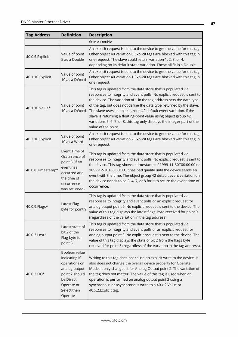
DNP3 Master Ethernet Driver
Tag Address Definition Description
fit in a Double.
40.0.5.ExplicitValue of point5 as a Double
An explicit request is sent to the device to get the value for this tag.Other object 40 variation 0 Explicit tags are blocked with this tag inone request. The slave could return variation 1, 2, 3, or 4;depending on its default static variation. These all fit in a Double.
40.1.10.ExplicitValue of point10 as a DWord
An explicit request is sent to the device to get the value for this tag.Other object 40 variation 1 Explicit tags are blocked with this tag inone request.
40.1.10.Value*Value of point10 as a DWord
This tag is updated from the data store that is populated viaresponses to integrity and event polls. No explicit request is sent tothe device. The variation of 1 in the tag address sets the data typeof the tag, but does not define the data type returned by the slave.The slave uses its object group 42 default event variation. If theslave is returning a floating-point value using object group 42variations 5, 6, 7, or 8, this tag only displays the integer part of thevalue of the point.
40.2.10.ExplicitValue of point10 as a Word
An explicit request is sent to the device to get the value for this tag.Other object 40 variation 2 Explicit tags are blocked with this tag inone request.
40.0.8.Timestamp*
Event Time ofOccurrence ofpoint 8 (if anevent hasoccurred andthe time ofoccurrencewas returned)
This tag is updated from the data store that is populated viaresponses to integrity and event polls. No explicit request is sent tothe device. This tag shows a timestamp of 1999-11-30T00:00:00 or1899-12-30T00:00:00. It has bad quality until the device sends anevent with the time. The object group 42 default event variation onthe device needs to be 3, 4, 7, or 8 for it to return the event time ofoccurrence.
40.0.9.Flags*Latest Flagbyte for point 9
This tag is updated from the data store that is populated viaresponses to integrity and event polls or an explicit request foranalog output point 9. No explicit request is sent to the device. Thevalue of this tag displays the latest flags' byte received for point 9(regardless of the variation in the tag address).
40.0.3.Lost*
Latest state ofbit 2 of theFlag byte forpoint 3
This tag is updated from the data store that is populated viaresponses to integrity and event polls or an explicit request foranalog output point 3. No explicit request is sent to the device. Thevalue of this tag displays the state of bit 2 from the flags bytereceived for point 3 (regardless of the variation in the tag address).
40.0.2.DO*
Boolean valueindicating ifoperations onanalog outputpoint 2 shouldbe DirectOperate orSelect thenOperate
Writing to this tag does not cause an explicit write to the device. Italso does not change the overall device property for OperateMode. It only changes it for Analog Output point 2. The variation ofthe tag does not matter. The value of this tag is used when anoperation is performed on analog output point 2 using asynchronous or asynchronous write to a 40.x.2.Value or40.x.2.Explicit tag.
www.ptc.com
57
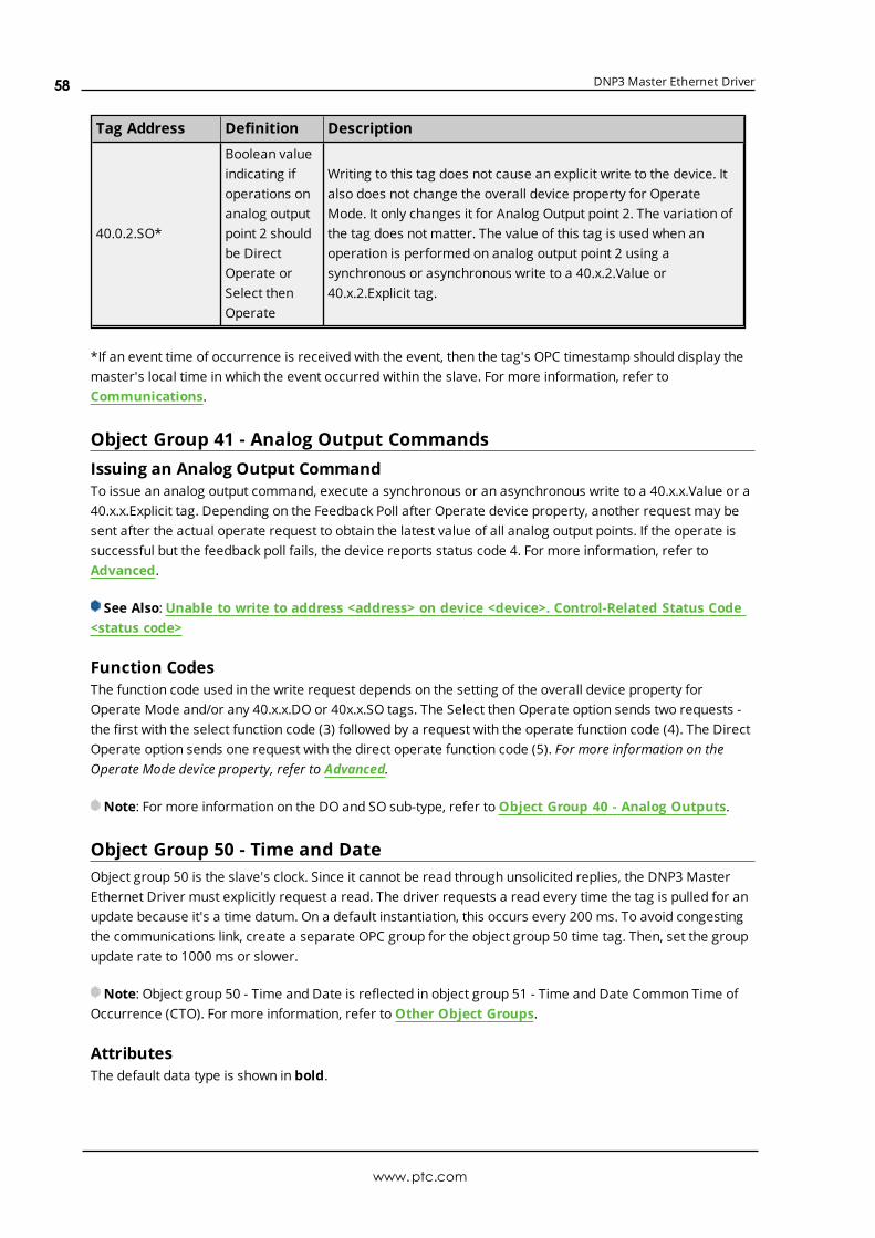
DNP3 Master Ethernet Driver
Tag Address Definition Description
40.0.2.SO*
Boolean valueindicating ifoperations onanalog outputpoint 2 shouldbe DirectOperate orSelect thenOperate
Writing to this tag does not cause an explicit write to the device. Italso does not change the overall device property for OperateMode. It only changes it for Analog Output point 2. The variation ofthe tag does not matter. The value of this tag is used when anoperation is performed on analog output point 2 using asynchronous or asynchronous write to a 40.x.2.Value or40.x.2.Explicit tag.
*If an event time of occurrence is received with the event, then the tag's OPC timestamp should display themaster's local time in which the event occurred within the slave. For more information, refer toCommunications.
Object Group 41 - Analog Output CommandsIssuing an Analog Output CommandTo issue an analog output command, execute a synchronous or an asynchronous write to a 40.x.x.Value or a40.x.x.Explicit tag. Depending on the Feedback Poll after Operate device property, another request may besent after the actual operate request to obtain the latest value of all analog output points. If the operate issuccessful but the feedback poll fails, the device reports status code 4. For more information, refer toAdvanced.
See Also: Unable to write to address <address> on device <device>. Control-Related Status Code<status code>
Function CodesThe function code used in the write request depends on the setting of the overall device property forOperate Mode and/or any 40.x.x.DO or 40x.x.SO tags. The Select then Operate option sends two requests -the first with the select function code (3) followed by a request with the operate function code (4). The DirectOperate option sends one request with the direct operate function code (5). For more information on theOperate Mode device property, refer to Advanced.
Note: For more information on the DO and SO sub-type, refer toObject Group 40 - Analog Outputs.
Object Group 50 - Time and DateObject group 50 is the slave's clock. Since it cannot be read through unsolicited replies, the DNP3 MasterEthernet Driver must explicitly request a read. The driver requests a read every time the tag is pulled for anupdate because it's a time datum. On a default instantiation, this occurs every 200 ms. To avoid congestingthe communications link, create a separate OPC group for the object group 50 time tag. Then, set the groupupdate rate to 1000 ms or slower.
Note: Object group 50 - Time and Date is reflected in object group 51 - Time and Date Common Time ofOccurrence (CTO). For more information, refer toOther Object Groups.
AttributesThe default data type is shown in bold.
www.ptc.com
58

DNP3 Master Ethernet Driver
OBJ.VAR Attributes .SUB Attribute Data Type Access
50.0 Value, Explicit Date Read Only
50.1 Value, Explicit Date Read Only
Note: Flags do not apply.
VariationsNumber Description
0 Time and Data Absolute time*
1 Time and Date Absolute time
*Allowed, but same as 50.1.
ExamplesTagAddress
Definition Description
50.0.ValueDate andtime savedin the slave
An explicit request for object 50 variation 1 is sent to the device to get thevalue for this tag. The update rate should not be set too often since it causestraffic every time the tag needs to be updated.
50.1.ValueDate andtime savedin the slave
An explicit request for object 50 variation 1 is sent to the device to get thevalue for this tag. The update rate should not be set too often since it causestraffic every time the tag needs to be updated.
50.0.ExplicitDate andtime savedin the slave
An explicit request for object 50 variation 1 is sent to the device to get thevalue for this tag. The update rate should not be too set often since it causestraffic every time the tag needs to be updated.
50.1.ExplicitDate andtime savedin the slave
An explicit request for object 50 variation 1 is sent to the device to get thevalue for this tag. The update rate should not be set too often since it causestraffic every time the tag needs to be updated.
Object Group 60 - Class Poll Data RequestWhen a Boolean True is written to these tags, object group 60 variations 1-4 initiate class 0-3 reads(respectively). Object group 60 tags can be used to 'manually' poll when the recommended event andintegrity class polling intervals cannot be used. This approach is not recommended, however, because caremust be taken to keep the requests in proper order. An integrity poll polls class 1, 2, 3, and 0 in that order, inone request, and without time lapses in between.
When using the object group 60 tags to poll for events, users should poll the event classes (variations 2, 3,and 4) before polling for class 0 static data (variation 1). This ensures that event data is received in thecorrect order and that the latest value is received after preceding events. Although a class object group 60.1request can be issued immediately after any of the event class object group 60.2, 3, or 4 requests, these arestill separate requests. Users risk losing any events that occurred between the last class 1, 2, or 3 requestand the class 0 request. A read of these tags always returns a Boolean False with good quality.
AttributesThese tags trigger commands on the DNP slave device when a True value is written. They read back as zeroor False.
www.ptc.com
59
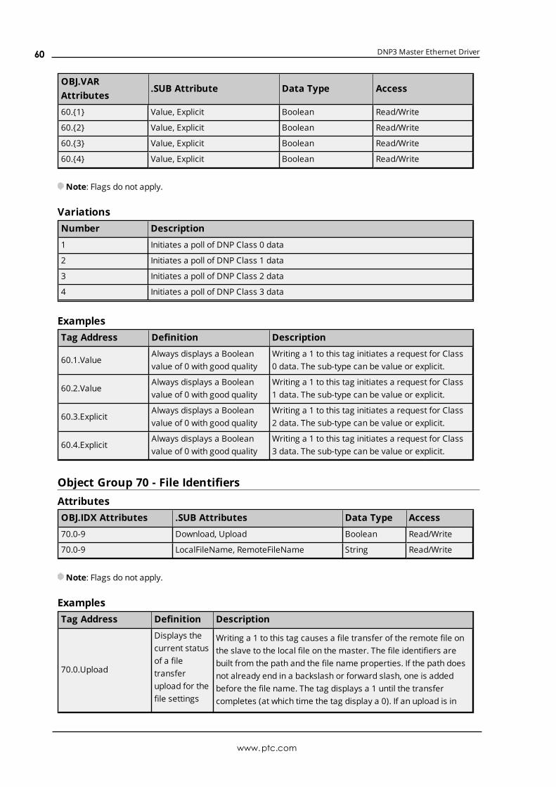
DNP3 Master Ethernet Driver
OBJ.VARAttributes
.SUB Attribute Data Type Access
60.{1} Value, Explicit Boolean Read/Write
60.{2} Value, Explicit Boolean Read/Write
60.{3} Value, Explicit Boolean Read/Write
60.{4} Value, Explicit Boolean Read/Write
Note: Flags do not apply.
VariationsNumber Description
1 Initiates a poll of DNP Class 0 data
2 Initiates a poll of DNP Class 1 data
3 Initiates a poll of DNP Class 2 data
4 Initiates a poll of DNP Class 3 data
ExamplesTag Address Definition Description
60.1.ValueAlways displays a Booleanvalue of 0 with good quality
Writing a 1 to this tag initiates a request for Class0 data. The sub-type can be value or explicit.
60.2.ValueAlways displays a Booleanvalue of 0 with good quality
Writing a 1 to this tag initiates a request for Class1 data. The sub-type can be value or explicit.
60.3.ExplicitAlways displays a Booleanvalue of 0 with good quality
Writing a 1 to this tag initiates a request for Class2 data. The sub-type can be value or explicit.
60.4.ExplicitAlways displays a Booleanvalue of 0 with good quality
Writing a 1 to this tag initiates a request for Class3 data. The sub-type can be value or explicit.
Object Group 70 - File IdentifiersAttributesOBJ.IDX Attributes .SUB Attributes Data Type Access
70.0-9 Download, Upload Boolean Read/Write
70.0-9 LocalFileName, RemoteFileName String Read/Write
Note: Flags do not apply.
ExamplesTag Address Definition Description
70.0.Upload
Displays thecurrent statusof a filetransferupload for thefile settings
Writing a 1 to this tag causes a file transfer of the remote file onthe slave to the local file on the master. The file identifiers arebuilt from the path and the file name properties. If the path doesnot already end in a backslash or forward slash, one is addedbefore the file name. The tag displays a 1 until the transfercompletes (at which time the tag display a 0). If an upload is in
www.ptc.com
60

DNP3 Master Ethernet Driver
Tag Address Definition Description
configured forindex 0.
0: No filetransferupload inprogress1: Upload inprogress
progress, writing a 0 to this tag causes the file transfer to beterminated.
70.5.Download
Displays thecurrent statusof a filetransferdownload forthe filesettingsconfigured forindex 5.
0: No filetransferdownload inprogress1: Downloadin progress
Writing a 1 to this tag causes a file transfer of the local file on themaster to the remote file on the slave. The file identifiers arebuilt from the path and the file name properties. If the path doesnot already end in a backslash or forward slash, one is addedbefore the file name. The tag displays a 1 until the transfercompletes (at which time the tag displays a 0). If a download is inprogress, writing a 0 to this tag causes the file transfer to beterminated.
70.6.LocalFileName
Displays thecurrentlyconfiguredlocal filename fromthe deviceproperty FileControl tabfor index 6.
This tag is Read Only unless the device Property for File NameWrites is set to Yes. If the tag has Read/Write access, writing tothis tag updates the corresponding File Control device property.The contents of the local file name property is appended to thelocal path to build the file identifier. A backslash or forward slashseparates the path from the file name.
70.8.RemoteFileName
Displays thecurrentlyconfiguredremote filename fromthe deviceproperty FileControl tabfor index 8.
This tag is Read Only unless the device Property for File NameWrites is set to Yes. If the tag has Read/Write access, writing tothis tag updates the corresponding File Control device property.The contents of the remote file name property is appended tothe remote path to build the file identifier. A backslash orforward slash separates the path from the file name.
Object Group 80 - Internal IndicationsAttributesThe default data type is shown in bold.
www.ptc.com
61
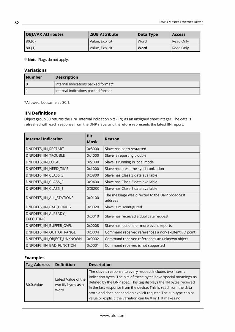
DNP3 Master Ethernet Driver
OBJ.VAR Attributes .SUB Attribute Data Type Access
80.{0} Value, Explicit Word Read Only
80.{1} Value, Explicit Word Read Only
Note: Flags do not apply.
VariationsNumber Description
0 Internal Indications packed format*
1 Internal Indications packed format
*Allowed, but same as 80.1.
IIN DefinitionsObject group 80 returns the DNP Internal Indication bits (IIN) as an unsigned short integer. The data isrefreshed with each response from the DNP slave, and therefore represents the latest IIN report.
Internal IndicationBitMask
Reason
DNPDEFS_IIN_RESTART 0x8000 Slave has been restarted
DNPDEFS_IIN_TROUBLE 0x4000 Slave is reporting trouble
DNPDEFS_IIN_LOCAL 0x2000 Slave is running in local mode
DNPDEFS_IIN_NEED_TIME 0x1000 Slave requires time synchronization
DNPDEFS_IIN_CLASS_3 0x0800 Slave has Class 3 data available
DNPDEFS_IIN_CLASS_2 0x0400 Slave has Class 2 data available
DNPDEFS_IIN_CLASS_1 0X0200 Slave has Class 1 data available
DNPDEFS_IIN_ALL_STATIONS 0x0100The message was directed to the DNP broadcastaddress
DNPDEFS_IIN_BAD_CONFIG 0x0020 Slave is misconfigured
DNPDEFS_IIN_ALREADY_EXECUTING
0x0010 Slave has received a duplicate request
DNPDEFS_IIN_BUFFER_OVFL 0x0008 Slave has lost one or more event reports
DNPDEFS_IIN_OUT_OF_RANGE 0x0004 Command received references a non-existent I/O point
DNPDEFS_IIN_OBJECT_UNKNOWN 0x0002 Command received references an unknown object
DNPDEFS_IIN_BAD_FUNCTION 0x0001 Command received is not supported
ExamplesTag Address Definition Description
80.0.ValueLatest Value of thetwo IIN bytes as aWord
The slave's response to every request includes two internalindication bytes. The bits of these bytes have special meanings asdefined by the DNP spec. This tag displays the IIN bytes receivedin the last response from the device. This is read from the datastore and does not send an explicit request. The sub-type can bevalue or explicit; the variation can be 0 or 1. It makes no
www.ptc.com
62

DNP3 Master Ethernet Driver
Tag Address Definition Description
difference.
80.1.ExplicitLatest Value of thetwo IIN bytes as aWord
The slave's response to every request includes two internalindication bytes. The bits of these bytes have special meanings asdefined by the DNP spec. This tag displays the IIN bytes receivedin the last response from the device. This is read from the datastore and does not send an explicit request. The sub-type can bevalue or explicit; the variation can be 0 or 1. It makes nodifference.
Object Group 87 - Data Sets.Value tags are populated by the data received from unsolicited events or integrity and event class polling..Explicit tags cause a device read: because tags for one set are blocked together, there is only one deviceread for the entire data set.
Notes:
1. At this time, data sets can only be defined in the slave. Users whomanually create tags must definethe correct data types. The master obtains the description of the data sets from the slave toautomatically define tags.
2. Object group 88 - Data Set - Snapshot data is reflected in object group 87 - Data Sets - Present valuetags. For more information, refer toOther Object Groups.
AttributesVariations for object group 87 do not equate to specific data types. Users must configure the tag with thesame data type that is configured in the slave for the specific data set element. Descriptions of the attributesare as follows:
l VAR: This attribute indicates the particular element of the data set.
l IDX: This attribute indicates the particular data set that is defined in the device.
The default data type is shown in bold.
OBJ.VAR.IDXAttributes
.SUBAttribute
Data Type Access
87.{0-1}.{0-65535}Value,Explicit
Byte, Char, Date, Double, DWord, Float, Long, Short,String, Word
Read Only
87.{2-32}.{0-65535}Value,Explicit
Byte, Char, Date, Double, DWord, Float, Long, Short,String, Word
Read/Write
87.{0}.{0-65535} Set Boolean Read/Write
VariationsDNP Object Flag DefinitionsTo get a data point's flags, the slave's definition of the data set must include an element specifically for DNPflags.
Examples
www.ptc.com
63

DNP3 Master Ethernet Driver
TagAddress
Definition Description
87.5.1.ExplicitDisplays the fifthelement of dataset 1
The .Explicit sub-type indicates that a request to the device for allelements of data set 1 occurs every time the tag needs to be updated.
87.7.2.ValueDisplays theseventh elementof data set 2
The .Value sub-type indicates the tags for data set 2 is only updatedfrom the data store that is populated through unsolicited messages orintegrity and event polls.
87.0.2.Set
Always displaysa Boolean valueof 0 with goodquality
Writing a 1 to this tag causes an object group 87 write operation ondata set 2. The write only takes place if there is data pending to bewritten due to a previous write to other .Value or .Explicit tags of thisdata set.
Object Group 110 - Octet String ObjectThese tags are only read explicitly once after start up. Explicit reads of the same object group and Variationare blocked together: A block that contains a failed tag continues to be read until the tag's quality changes togood or is removed.
Notes:
1. Object group 110 - Octet String value is reflected in object group 111 - Octet String Event Change.For more information, refer to Other Object Groups.
2. Zero-length string tags return bad quality.
AttributesThe default data type is shown in bold.
OBJ.IDX Attributes .SUB Attribute Data Type Access
110.{0-65535} Value, Explicit - takes up to 255 characters String Read/Write
Note: Flags do not apply.
VariationsNumber Description
String Length Octet String
ExamplesTagAddress
Definition Description
110.0.ValueValue ofpoint 0 as aString
If a value for this tag has not been received from the device, then an explicitrequest is sent. Once the point has been initialized, the tag receives itsupdates from the data store. A second explicit request is only issued if theslave or master restarts. Other object 110 explicit and value tags areblocked with this tag in one request. The sub-type can be Value or Explicit: itmakes no difference.
www.ptc.com
64

DNP3 Master Ethernet Driver
TagAddress
Definition Description
110.5.ExplicitValue ofpoint 5 as aString
If a value for this tag has not been received from the device, then an explicitrequest is sent. Once the point has been initialized, the tag receives itsupdates from the data store. A second explicit request is only issued if theslave or master restarts. Other object 110 explicit and value tags areblocked with this tag in one request. The sub-type can be value or explicit: itmakes no difference.
Object Group 120 - Authentication ObjectThe authentication object tags are internal statistics for DNP authentication.
AttributesThe default data type is shown in bold.
OBJ.VAR Attributes.SUBAttribute
DescriptionDataType
Access
120.KeyStatRQTXValueReset
Key status requests sent to outstation.DWordBool
Read OnlyRead/Write
120.KeyStatRQRXValueReset
Key status responses received fromoutstation.
DWordBool
Read OnlyRead/Write
120.KeyStatRQRX_NoInitValueReset
Key status request responded with anuninitialized failure.
DWordBool
Read OnlyRead/Write
120.KeyStatRQRX_CommFail
ValueReset
Key status request responded with acommunications failure.
DWordBool
Read OnlyRead/Write
120.KeyStatRQRX_AuthFailValueReset
Key status request responded with anauthentication failure.
DWordBool
Read OnlyRead/Write
120.KeyChangeTXValueReset
Key change requests sent to theoutstation.
DWordBool
Read OnlyRead/Write
120.AggrModeRQTXValueReset
Aggressive mode requests sent to theoutstation.
DWordBool
Read OnlyRead/Write
120.AggrModeResponseRXValueReset
Aggressive mode responses from theoutstation
DWordBool
Read OnlyRead/Write
120.AggrModeResponseRX_Failed
ValueReset
Aggressive mode request respondedwith a failure.
DWordBool
Read OnlyRead/Write
120.ChallRQTXValueReset
Challenge requests sent to theoutstation.
DWordBool
Read OnlyRead/Write
120.ChallRQRXValueReset
Challenge requests received from theoutstation.
DWordBool
Read OnlyRead/Write
120.CriticalChallRQTXValueReset
Critical challenge requests sent to theoutstation.
DWordBool
Read OnlyRead/Write
120.CriticalChallRQRXValueReset
Critical challenge requests receivedfrom the outstation.
DWordBool
Read OnlyRead/Write
120.ChallReplyTXValueReset
Challenge responses sent to theoutstation.
DWordBool
Read OnlyRead/Write
www.ptc.com
65

DNP3 Master Ethernet Driver
OBJ.VAR Attributes.SUBAttribute
DescriptionDataType
Access
120.ChallReplyRXValueReset
Challenge responses received from theoutstation.
DWordBool
Read OnlyRead/Write
120.ChallReplyRX_FailedValueReset
Challenge responses with a failure.DWordBool
Read OnlyRead/Write
120.ErrorTX_InvalidValueReset
Invalid errors sent to outstation.DWordBool
Read OnlyRead/Write
120.ErrorTX_UnexpectedReply
ValueReset
Unexpected reply errors sent tooutstation.
DWordBool
Read OnlyRead/Write
120.ErrorTX_NoReplyValueReset
No reply errors sent to outstation.DWordBool
Read OnlyRead/Write
120.ErrorTX_AggrModeNotSupported
ValueReset
Aggressive mode not supported errorssent to outstation.
DWordBool
Read OnlyRead/Write
120.ErrorTX_HMACAlgNotSupported
ValueReset
HMAC algorithm not supported errorssent to outstation.
DWordBool
Read OnlyRead/Write
120.ErrorTX_KeyWrapAlgNotSupported
ValueReset
Key wrap algorithm not supportederrors sent to outstation.
DWordBool
Read OnlyRead/Write
120.ErrorTX_UserAccessDenied
ValueReset
User access denied errors sent tooutstation.
DWordBool
Read OnlyRead/Write
120.ErrorTX_KeyChangeDenied
ValueReset
Key change denied errors sent tooutstation.
DWordBool
Read OnlyRead/Write
120.ErrorTX_InvalidSignValueReset
Invalid signature errors sent tooutstation.
DWordBool
Read OnlyRead/Write
120.ErrorTX_InvalidCertValueReset
Invalid certificate errors sent tooutstation.
DWordBool
Read OnlyRead/Write
120.ErrorTX_UnknownUserValueReset
Unknown user errors sent to outstation.DWordBool
Read OnlyRead/Write
120.ErrorTX_VendorSpecificValueReset
Vendor-specific errors sent tooutstation.
DWordBool
Read OnlyRead/Write
120.ErrorRX_InvalidValueReset
Invalid errors received from outstation.DWordBool
Read OnlyRead/Write
120.ErrorRX_UnexpectedReply
ValueReset
Unexpected reply errors received fromoutstation.
DWordBool
Read OnlyRead/Write
120.ErrorRX_NoReplyValueReset
No reply errors received fromoutstation.
DWordBool
Read OnlyRead/Write
120.ErrorRX_AggrModeNotSupported
ValueReset
Aggressive mode not supported errorsreceived from outstation.
DWordBool
Read OnlyRead/Write
120.ErrorRX_HMACAlgNotSupported
ValueReset
HMAC algorithm not supported errorsreceived from outstation.
DWordBool
Read OnlyRead/Write
120.ErrorRX_KeyWrapAlgNotSupported
ValueReset
Key wrap algorithm not supportederrors received from outstation.
DWordBool
Read OnlyRead/Write
120.ErrorRX_UserAccessDenied
ValueReset
User access denied errors receivedfrom outstation.
DWordBool
Read OnlyRead/Write
120.ErrorRX_ Value Key change denied errors received DWord Read Only
www.ptc.com
66

DNP3 Master Ethernet Driver
OBJ.VAR Attributes.SUBAttribute
DescriptionDataType
Access
KeyChangeDenied Reset from outstation. Bool Read/Write
120.ErrorRX_InvalidSignValueReset
Invalid signature errors received fromoutstation.
DWordBool
Read OnlyRead/Write
120.ErrorRX_InvalidCertValueReset
Invalid certificate errors received fromoutstation.
DWordBool
Read OnlyRead/Write
120.ErrorRX_UnknownUserValueReset
Unknown user errors received fromoutstation.
DWordBool
Read OnlyRead/Write
120.ErrorRX_VendorSpecificValueReset
Vendor-specific errors received fromoutstation.
DWordBool
Read OnlyRead/Write
ExamplesTag Address Definition Description
120.KeyStatRQTX.ValueValue of the KeyStatRQTXauthentication statistic
The number of key status requests sent to theoutstation since startup or last reset.
120.KeyStatRQTX.ResetReset the KeyStatRQTXauthentication statistic
The KeyStatRQTX statistic is cleared with a writevalue of 1.
Other Object GroupsCertain objects are not used in the driver due to the fact that their values are reflected in other objects.
Object NameReflected inObject
Name
2 Binary Input Change Event 1 Binary Input State
4 Double Bit Input Change Event 3 Double Bit Input State
11 Binary Output Change Event 10 Binary Output State
12 Control Relay Output Block 10 Binary Output State
13 Binary Output Command Event 10 Binary Output State
22 Counter Event Change 20 Counter Value
23 Frozen Counter Event Change 21 Frozen Counter Value
32 Analog Input Change Event 30 Analog Input Value
41 Analog Output Write 40 Analog Output Value
42 Analog Output Change Event 40 Analog Output Value
43 Analog Output Command Event 40 Analog Output Value
51Time and Date Common Time of Occurrence(CTO)
50 Time and Date
88 Data Set - Snapshot 87Data Set - PresentValue
111 Octet String Event Change 110 Octet String Value
Internal Tags
www.ptc.com
67

DNP3 Master Ethernet Driver
Tag DescriptionDataType
Access
_AuthCurrentUserNumberThis tag allows the authentication Current UserNumber device property to be changed from a clientapplication. Valid values range from 0 to 65535.
Word Read/Write
_ChannelResponseTimeoutThis tag allows the Request Timeout channel propertyto be changed from a client application. Valid valuesrange from 100 to 3600000.
DWord Read/Write
_DestinationHostThis tag allows the Destination Host channel propertyto be changed from a client application. The Hostaddress must be formatted correctly.
String Read/Write
_DestinationPortThis tag allows the Destination Port channel propertyto be changed from a client application. Valid valuesrange from 1 to 65535.
Word Read/Write
_DeviceRequestQueueDepth
This tag indicates the current depth of the queueused for storing device requests. It is useful fordiagnostic purposes for issues such as tag updatedelays. Although a zero or steady value is expected, anon-zero value is not a problem unless it continues togrow and causes a delay in tag updates. For example,if the project has a device defined with 100 blocks of.Explicit tags and the _DeviceRequestQueueDepth tagvalue is 100, then something is blocking the tags frombeing updated on time.
DWord Read Only
_DeviceRequestTimeoutThis tag allows the Request Timeout device propertyto be changed from a client application. Valid valuesrange from 0 to 3600000.
DWord Read/Write
_EventClass1PollInterval*This tag allows the Event Class Poll 1 Interval deviceproperty to be changed from a client application.Valid values range from 0 to 86400 seconds.
DWord Read/Write
_EventClass2PollInterval*This tag allows the Event Class Poll 2 Interval deviceproperty to be changed from a client application.Valid values range from 0 to 86400 seconds.
DWord Read/Write
_EventClass3PollInterval*This tag allows the Event Class 3 Poll Interval deviceproperty to be changed from a client application.Valid values range from 0 to 86400 seconds.
DWord Read/Write
_IntegrityPollIntervalThis tag allows the Integrity Poll device property to bechanged from a client application. Valid values rangefrom 0 to 2592000.
DWord Read/Write
_MasterAddressThis tag allows the master address device property tobe changed from a client application. Valid valuesrange from 0 to 65519.
DWord Read/Write
_Protocol
This tag allows the Ethernet Protocol channelproperty to be changed from a client application.Valid values range from 0 to 1. A value of 0 indicatesTCP/IP; a value of 1 indicates UDP.
Byte Read/Write
_SlaveAddress This tag allows the slave address device property to DWord Read/Write
www.ptc.com
68
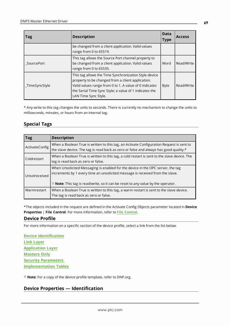
DNP3 Master Ethernet Driver
Tag DescriptionDataType
Access
be changed from a client application. Valid valuesrange from 0 to 65519.
_SourcePortThis tag allows the Source Port channel property tobe changed from a client application. Valid valuesrange from 0 to 65535.
Word Read/Write
_TimeSyncStyle
This tag allows the Time Synchronization Style deviceproperty to be changed from a client application.Valid values range from 0 to 1. A value of 0 indicatesthe Serial Time Sync Style; a value of 1 indicates theLAN Time Sync Style.
Byte Read/Write
* Any write to this tag changes the units to seconds. There is currently no mechanism to change the units tomilliseconds, minutes, or hours from an internal tag.
Special Tags
Tag Description
ActivateConfigWhen a Boolean True is written to this tag, an Activate Configuration Request is sent tothe slave device. The tag is read back as zero or false and always has good quality.*
ColdrestartWhen a Boolean True is written to this tag, a cold restart is sent to the slave device. Thetag is read back as zero or false.
Unsolreceived
When Unsolicited Messaging is enabled for the device in the OPC server, the tagincrements by 1 every time an unsolicited message is received from the slave.
Note: This tag is read/write, so it can be reset to any value by the operator.
Warmrestart When a Boolean True is written to this tag, a warm restart is sent to the slave device.The tag is read back as zero or false.
*The objects included in the request are defined in the Activate Config Objects parameter located inDeviceProperties | File Control. For more information, refer to File Control.
Device ProfileFor more information on a specific section of the device profile, select a link from the list below.
Device IdentificationLink LayerApplication LayerMasters OnlySecurity ParametersImplementation Tables
Note: For a copy of the device profile template, refer to DNP.org.
Device Properties — Identification
www.ptc.com
69

DNP3 Master Ethernet Driver
Component Description Current Value Methods
DeviceFunction
Masters send DNP requests. Master N/A
Device Name
This is the model and name of the device,which should be sufficient to distinguish itfrom any other device from the sameorganization.
DNP Master Ethernet N/A
HardwareVersion
N/A
- Windows 7- Windows Server 2008- Windows Vista Business/ Ultimate- Windows Server 2003SP2- Windows XP SP2
N/A
SoftwareVersion
N/A v.5 N/A
Device ProfileDocumentVersion
The version of the device profile Document isindicated by a whole number incrementedwith each new release.
4 N/A
SupportedWITS MajorVersion
The major version of the WITS Standardimplemented by the device.
1 N/A
SupportedWITS MinorVersion
The minor version of the WITS Standardimplemented by the device.
0 N/A
DNP LevelsSupported forRequests
The DNP3 level to which the device conformsfully. Requests can be indicated independently.
3 N/A
DNP LevelsSupported forResponses
The DNP3 level to which the device conformsfully. Responses can be indicatedindependently.
3 N/A
SupportedFunctionBlocks
N/A
Object 0 - Attributeobjects, Data Sets, FileTransfer, Secureauthentication, andFunction Code 31 -Activate Configuration.
N/A
NotableAdditions
This brief description intends to identify themost obvious features that the devicesupports, in addition to the highest supportedlevel of DNP. The complete list of features isdescribed in the Implementation Table.
- Enabling and disablingunsolicited responses onan individual class basis.- Double-bit Input objects.- Variations with time forFrozen Counters, FrozenCounter Events, andAnalog Input Events.- Floating-point variationsfor both Analog Inputs
For moreinformation,refer toAddressDescriptions.
www.ptc.com
70
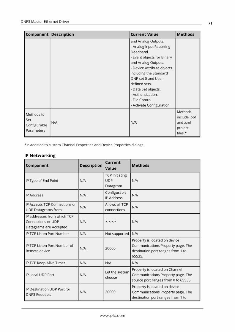
DNP3 Master Ethernet Driver
Component Description Current Value Methods
and Analog Outputs.- Analog Input ReportingDeadband.- Event objects for Binaryand Analog Outputs.- Device Attribute objectsincluding the StandardDNP set 0 and User-defined sets.- Data Set objects.- Authentication.- File Control.- Activate Configuration.
Methods toSetConfigurableParameters
N/A N/A
Methodsinclude .opfand .xmlprojectfiles.*
*In addition to custom Channel Properties and Device Properties dialogs.
IP Networking
Component DescriptionCurrentValue
Methods
IP Type of End Point N/ATCP InitiatingUDPDatagram
N/A
IP Address N/AConfigurableIP Address
N/A
IP Accepts TCP Connections orUDP Datagrams from:
N/AAllows all TCPconnections
N/A
IP addresses from which TCPConnections or UDPDatagrams are Accepted
N/A *.*.*.* N/A
IP TCP Listen Port Number N/A Not supported N/A
IP TCP Listen Port Number ofRemote device
N/A 20000
Property is located on deviceCommunications Property page. Thedestination port ranges from 1 to65535.
IP TCP Keep-Alive Timer N/A N/A N/A
IP Local UDP Port N/ALet the systemchoose
Property is located on ChannelCommunications Property page. Thesource port ranges from 0 to 65535.
IP Destination UDP Port forDNP3 Requests
N/A 20000Property is located on deviceCommunications Property page. Thedestination port ranges from 1 to
www.ptc.com
71

DNP3 Master Ethernet Driver
Component DescriptionCurrentValue
Methods
65535.
IP Multiple OutstationConnections - Master
N/ASupportsmultiple
N/A
IP Time SynchronizationSupport
N/A
DNP3 LANprocedure(function code24)
Property is located on deviceCommunications Property page.
Link Layer
Component DescriptionCurrentValue
Methods
Data LinkAddress
This indicates if the link addressis configurable over the entirevalid range of 0 to 65519.
Rangesfrom 0 to65519.
Slave address propertyis located on deviceCommunicationsProperty page.
SendsConfirmedUser DataFrames
This is a list of conditions under which the devicetransmits the following confirmed link layerservices:
TEST_LINK_STATESRESET_LINK_STATESCONFIRMED_USER_DATA
Never N/A
Data LinkLayerConfirmationTimeout
This timeout applies to any secondary data linkmessage that requires a confirmation or response(such as link reset, link status, user data, and soforth).
2seconds
N/A
MaximumDataLink Retries
This is the number of times thatthe device retransmits a framethat requests Link Layerconfirmation.
3 retries N/A
MaximumNumber ofOctetsTransmittedina Data LinkFrame
This number includes the checksum. With a lengthfield of 255, the maximum size would be 292.
292 N/A
MaximumNumber ofOctets thatcan beReceived in aDataLink Frame
This number includes the checksum. With a lengthfield of 255, the maximum size would be 292. Thedevice must be able to receive 292 octets to becompliant.
292 N/A
www.ptc.com
72

DNP3 Master Ethernet Driver
*Data link addresses 0xFFF0 through 0xFFFF are reserved for broadcast or other special purposes.
Application Layer
Component DescriptionCurrentValue
Methods
Maximum Number ofOctets Transmitted in anApplication Layer Fragmentother than File Transfer
This size does not include any transport or frameoctets.Masters must provide a setting less than or equal to249.
249 N/A
Maximum Number ofOctets Transmitted in anApplication Layer FragmentContaining File Transfer
N/A N/A N/A
Maximum Number ofOctets that can beReceived in an ApplicationLayer Fragment
This size does not include any transport or frameoctets. Masters must provide a setting greater thanor equal to 2048.
2048 N/A
Timeout waiting forComplete Application LayerFragment
Timeout if all frames of a message fragment are notreceived in the specified time. It is measured fromthe time that the first frame of a fragment isreceived until the last frame is received.
N/A N/A
Maximum Number ofobjects Allowed in a SingleControl Request for CROB(g12)
N/A N/A N/A
Maximum Number ofobjects Allowed in a SingleControl Request for AnalogOutputs (g41)
N/A N/A N/A
Maximum Number ofobjects Allowed in a SingleControl Request for DataSets (g85, 86, 87)
N/A N/A N/A
Supports Mixing objectgroups* in the SameControl Request
N/A N/A N/A
*AOBs, cROBs, and Data Sets.
Masters Only
www.ptc.com
73

DNP3 Master Ethernet Driver
Component DescriptionCurrentValue
Methods
Timeout Waiting forComplete ApplicationLayer Response
Timeout onMaster if all fragmentsof a response message are notreceived in the specified time.
10000 ms
Property is located onthe ChannelCommunicationsProperty page.Supported responsetimeouts are 100 to3600000.
Maximum ApplicationLayer Retries for RequestMessages
This is the number of times aMaster retransmits an applicationlayer request message if a responseis not received. This parametermust never cause a Master toretransmit control or time syncmessages.
0
Max. Timeoutsproperty is located onthe DeviceCommunicationsProperty page.Supported timeoutsare 1 to 10 (0 to 9retries).
Incremental TimeoutWaiting for First or NextFragment of anApplication LayerResponse
N/A None N/A
Security Parameters
Component DescriptionCurrentValue
Methods
DNP3 DeviceSupport forSecureAuthentication
Indicates whether the device supportssecure authentication (and, if so, whatversion).
Version 2
Authentication can beenabled on theAuthentication tab in deviceproperties. The UserNumber and Update Keytag properties can beconfigured in the UserNumbers/Update Key tab indevice properties.
MaximumNumber ofUsers
The device must support details for eachuser. Users are identified by a 16 bit usernumber. Indicates the actual limit to thenumber of simultaneous users that can besupported.
10
The maximum number ofusers cannot be configured,but the User Number andUpdate Keys can beconfigured in deviceproperties.
SecurityMessageResponseTimeout
The authentication of critical messages mayinvolve additional message exchanges(challenges and responses), which canrequire an extension to the normal DNP3message response timeout. This timeout
2000milliseconds
The Reply Timeout propertyis located on theAuthentication tab in deviceproperties. The valid rangeis 0 to 300000 milliseconds.
www.ptc.com
74
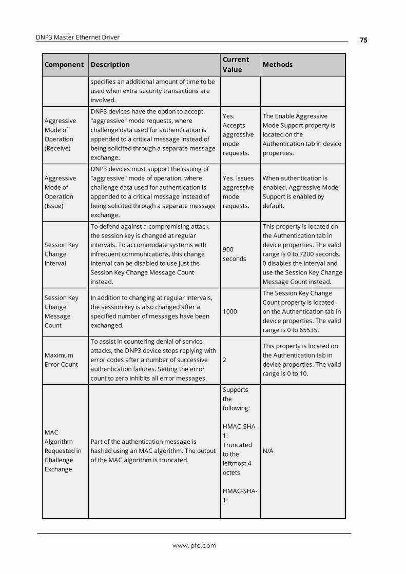
DNP3 Master Ethernet Driver
Component DescriptionCurrentValue
Methods
specifies an additional amount of time to beused when extra security transactions areinvolved.
AggressiveMode ofOperation(Receive)
DNP3 devices have the option to accept"aggressive" mode requests, wherechallenge data used for authentication isappended to a critical message instead ofbeing solicited through a separate messageexchange.
Yes.Acceptsaggressivemoderequests.
The Enable AggressiveMode Support property islocated on theAuthentication tab in deviceproperties.
AggressiveMode ofOperation(Issue)
DNP3 devices must support the issuing of"aggressive" mode of operation, wherechallenge data used for authentication isappended to a critical message instead ofbeing solicited through a separate messageexchange.
Yes. Issuesaggressivemoderequests.
When authentication isenabled, Aggressive ModeSupport is enabled bydefault.
Session KeyChangeInterval
To defend against a compromising attack,the session key is changed at regularintervals. To accommodate systems withinfrequent communications, this changeinterval can be disabled to use just theSession Key Change Message Countinstead.
900seconds
This property is located onthe Authentication tab indevice properties. The validrange is 0 to 7200 seconds.0 disables the interval anduse the Session Key ChangeMessage Count instead.
Session KeyChangeMessageCount
In addition to changing at regular intervals,the session key is also changed after aspecified number of messages have beenexchanged.
1000
The Session Key ChangeCount property is locatedon the Authentication tab indevice properties. The validrange is 0 to 65535.
MaximumError Count
To assist in countering denial of serviceattacks, the DNP3 device stops replying witherror codes after a number of successiveauthentication failures. Setting the errorcount to zero inhibits all error messages.
2
This property is located onthe Authentication tab indevice properties. The validrange is 0 to 10.
MACAlgorithmRequested inChallengeExchange
Part of the authenticationmessage ishashed using anMAC algorithm. The outputof the MAC algorithm is truncated.
Supportsthefollowing:
HMAC-SHA-1: Truncatedto theleftmost 4octets
HMAC-SHA-1:
N/A
www.ptc.com
75

DNP3 Master Ethernet Driver
Component DescriptionCurrentValue
Methods
Truncatedto theleftmost 8octets
HMAC-SHA-1: Truncatedto theleftmost 10octets
HMAC-SHA-256:Truncatedto theleftmost 8octets
HMAC-SHA-256:Truncatedto theleftmost 16octets
Key-wrapAlgorithm toEncryptSession Keys
When a session key is updated, it isencrypted using AES-128. Other algorithmsare optional.
SupportsAES-128
Not configurable
Implementation TablesThe following implementation tables identify which object groups and variations, function codes, andqualifiers are supported by the Master in both requests and responses. The Request columns identify allrequests that may be sent by the Master, or all requests that must be parsed by a slave. The Responsecolumns identify all responses that must be parsed by the Master, or all responses that may be sent by aslave.
Note: Both the Request Function Code and the Response Function Code are in decimal.
Code Description
1 Read
2 Write
3 Select
4 Operate
5 Direct operate
www.ptc.com
76

DNP3 Master Ethernet Driver
Code Description
6 Direct operate, no acknowledgment
20 Enable unsolicited responses
21 Disable unsolicited responses
25 Open file
26 Close file
27 Delete file
28 Get file information
29 Authenticate file
30 Abort file transfer
31 Activate configuration
32 Authentication request
129 Response
130 Unsolicited response
131 Authentication response
Note: Both the Request Qualifier Code and the Response Qualifier Code are in hexadecimal.
Code Description
00 8-bit start-stop
01 16-bit start-stop
06 No range, or all
07 8-bit limited quantity
08 16-bit limited quantity
17 8-bit index
18 16-bit index
5B Free format
Object Group 0 - Device Attributes
Variation DescriptionRequestFunctionCode
RequestQualifierCodes
ResponseFunctionCodes
ResponseQualifierCodes
1-253Standard Set 0 andUser Defined Sets
12
00, 0600
129N/A
00, 17N/A
254Non-specific allattributes request
1 00, 06 129 00, 17
255List of attributevariations
1 00, 06 129 00, 5B
Object Group 1 - Binary Inputs
www.ptc.com
77
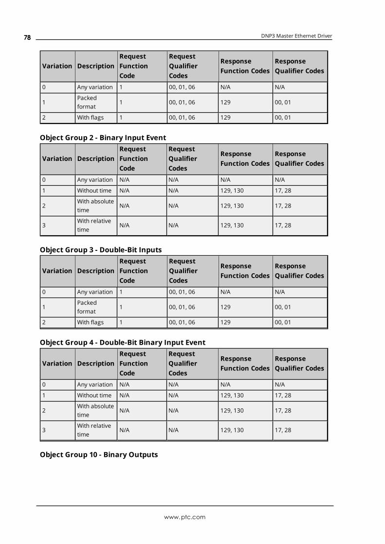
DNP3 Master Ethernet Driver
Variation DescriptionRequestFunctionCode
RequestQualifierCodes
ResponseFunction Codes
ResponseQualifier Codes
0 Any variation 1 00, 01, 06 N/A N/A
1Packedformat
1 00, 01, 06 129 00, 01
2 With flags 1 00, 01, 06 129 00, 01
Object Group 2 - Binary Input Event
Variation DescriptionRequestFunctionCode
RequestQualifierCodes
ResponseFunction Codes
ResponseQualifier Codes
0 Any variation N/A N/A N/A N/A
1 Without time N/A N/A 129, 130 17, 28
2With absolutetime
N/A N/A 129, 130 17, 28
3With relativetime
N/A N/A 129, 130 17, 28
Object Group 3 - Double-Bit Inputs
Variation DescriptionRequestFunctionCode
RequestQualifierCodes
ResponseFunction Codes
ResponseQualifier Codes
0 Any variation 1 00, 01, 06 N/A N/A
1Packedformat
1 00, 01, 06 129 00, 01
2 With flags 1 00, 01, 06 129 00, 01
Object Group 4 - Double-Bit Binary Input Event
Variation DescriptionRequestFunctionCode
RequestQualifierCodes
ResponseFunction Codes
ResponseQualifier Codes
0 Any variation N/A N/A N/A N/A
1 Without time N/A N/A 129, 130 17, 28
2With absolutetime
N/A N/A 129, 130 17, 28
3With relativetime
N/A N/A 129, 130 17, 28
Object Group 10 - Binary Outputs
www.ptc.com
78

DNP3 Master Ethernet Driver
Variation DescriptionRequestFunctionCode
RequestQualifierCodes
ResponseFunction Codes
ResponseQualifier Codes
0 Any variation 1 00, 01, 06 N/A N/A
1Packedformat
1 00, 01, 06 129 00, 01
2Output statuswith flags
1 00, 01, 06 129 00, 01
Object Group 11 - Binary Output Events
Variation DescriptionRequestFunctionCode
RequestQualifierCodes
ResponseFunction Codes
ResponseQualifier Codes
0 Any variation N/A N/A N/A N/A
1Statuswithout time
N/A N/A 129, 130 17, 28
2Status withtime
N/A N/A 129, 130 17, 28
Object Group 12 -Binary Command
Variation DescriptionRequestFunctionCode
RequestQualifierCodes
ResponseFunctionCodes
ResponseQualifierCodes
1Control RelayOutput Block(CROB)
3, 4, 5, 6 17, 28 129 Echo of request.
Object Group 20 - Counters
Variation DescriptionRequestFunctionCode
RequestQualifierCodes
ResponseFunction Codes
ResponseQualifier Codes
0 Any variation 1 00, 01, 06 N/A N/A
132-bit withflag
1 00, 01, 06 129 00, 01
216-bit withflag
1 00, 01, 06 129 00, 01
532-bit withoutflag
1 00, 01, 06 129 00, 01
616-bit withoutflag
1 00, 01, 06 129 00, 01
Object Group 21 - Frozen Counters
www.ptc.com
79

DNP3 Master Ethernet Driver
Variation DescriptionRequestFunctionCode
RequestQualifierCodes
ResponseFunction Codes
ResponseQualifier Codes
0 Any variation 1 00, 01, 06 N/A N/A
132-bit withflag
1 00, 01, 06 129 00, 01
216-bit withflag
1 00, 01, 06 129 00, 01
532-bit withflag and time
1 00, 01, 06 129 00, 01
616-bit withflag and time
1 00, 01, 06 129 00, 01
932-bit withoutflag
1 00, 01, 06 129 00, 01
1016-bit withoutflag
1 00, 01, 06 129 00, 01
Object Group 22 - Counter Event
Variation DescriptionRequestFunctionCode
RequestQualifierCodes
ResponseFunction Codes
ResponseQualifier Codes
0 Any variation N/A N/A N/A N/A
132-bit withflag
N/A N/A 129, 130 17, 28
216-bit withflag
N/A N/A 129, 130 17, 28
532-bit withflag and time
N/A N/A 129, 130 17, 28
616-bit withflag and time
N/A N/A 129, 130 17, 28
Object Group 23 - Frozen Counter Event
Variation DescriptionRequestFunctionCode
RequestQualifierCodes
ResponseFunction Codes
ResponseQualifier Codes
0 Any variation N/A N/A N/A N/A
132-bit withflag
N/A N/A 129, 130 17, 28
216-bit withflag
N/A N/A 129, 130 17, 28
532-bit withflag and time
N/A N/A 129, 130 17, 28
616-bit withflag and time
N/A N/A 129, 130 17, 28
www.ptc.com
80

DNP3 Master Ethernet Driver
Object Group 30 - Analog Input
Variation DescriptionRequestFunctionCode
RequestQualifierCodes
ResponseFunctionCodes
ResponseQualifierCodes
0 Any variation 1 00, 01, 06 N/A N/A
1 32-bit with flag 1 00, 01, 06 129 00, 01
2 16-bit with flag 1 00, 01, 06 129 00, 01
3 32-bit without flag 1 00, 01, 06 129 00, 01
4 16-bit without flag 1 00, 01, 06 129 00, 01
5Single-precisionfloating-point withflag
1 00, 01, 06 129 00, 01
6Double-precisionfloating-point withflag
1 00, 01, 06 129 00, 01
Object Group 32 - Analog Input Event
Variation DescriptionRequestFunctionCode
RequestQualifierCodes
ResponseFunctionCodes
ResponseQualifierCodes
0 Any variation N/A N/A N/A N/A
1 32-bit without time N/A N/A 129, 130 17, 28
2 16-bit without time N/A N/A 129, 130 17, 28
3 32-bit with time N/A N/A 129, 130 17, 28
4 16-bit with time N/A N/A 129, 130 17, 28
5Single-precisionfloating-point withouttime
N/A N/A 129, 130 17, 28
6Double-precisionfloating-point withouttime
N/A N/A 129, 130 17, 28
7Single-precisionfloating-point with time
N/A N/A 129, 130 17, 28
8Double-precisionfloating-point with time
N/A N/A 129, 130 17, 28
Object Group 34 - Analog Inputs Deadband
Variation DescriptionRequestFunctionCode
RequestQualifierCodes
ResponseFunctionCodes
ResponseQualifierCodes
0 Any variation 1 00, 01, 06 N/A N/A
1 16-bit12
00, 01, 0600, 01
129N/A
00, 01N/A
www.ptc.com
81

DNP3 Master Ethernet Driver
Variation DescriptionRequestFunctionCode
RequestQualifierCodes
ResponseFunctionCodes
ResponseQualifierCodes
2 32-bit12
00, 01, 0600, 01
129N/A
00, 01N/A
3Single-precisionfloating-point
12
00, 01, 0600, 01
129N/A
00, 01N/A
Object Group 40 - Analog Outputs
Variation DescriptionRequestFunctionCode
RequestQualifierCodes
ResponseFunctionCodes
ResponseQualifierCodes
0 Any variation 1 00, 01, 06 N/A N/A
1 32-bit with flag 1 00, 01, 06 129 00, 01
2 16-bit with flag 1 00, 01, 06 129 00, 01
3Single-precisionfloating-point withflag
1 00, 01, 06 129 00, 01
4Double-precisionfloating-point withflag
1 00, 01, 06 129 00, 01
Object Group 41 - Analog Output Status
Variation DescriptionRequestFunctionCode
RequestQualifierCodes
ResponseFunctionCodes
ResponseQualifierCodes
1 32-bit 3, 4, 5, 6 17, 28 129 Echo of request
2 16-bit 3, 4, 5, 6 17, 28 129 Echo of request
3Single-precisionfloating-point
3, 4, 5, 6 17, 28 129 Echo of request
4Double-precisionfloating-point
3, 4, 5, 6 17, 28 129 Echo of request
Object Group 42 - Analog Output Event
Variation DescriptionRequestFunctionCode
RequestQualifierCodes
ResponseFunctionCodes
ResponseQualifierCodes
0 Any variation N/A N/A N/A N/A
1 32-bit without time N/A N/A 129, 130 17, 28
2 16-bit without time N/A N/A 129, 130 17, 28
3 32-bit with time N/A N/A 129, 130 17, 28
4 16-bit with time N/A N/A 129, 130 17, 28
5 Single-precision N/A N/A 129, 130 17, 28
www.ptc.com
82

DNP3 Master Ethernet Driver
Variation DescriptionRequestFunctionCode
RequestQualifierCodes
ResponseFunctionCodes
ResponseQualifierCodes
floating point withouttime
6Double-precisionfloating-point withouttime
N/A N/A 129, 130 17, 28
7Single-precisionfloating-point with time
N/A N/A 129, 130 17, 28
8Double-precisionfloating-point with time
N/A N/A 129, 130 17, 28
Object Group 50 - Time and Date
Variation DescriptionRequestFunctionCode
RequestQualifierCodes
ResponseFunctionCodes
ResponseQualifierCodes
1 Absolute time12
0707
129N/A
07N/A
3Absolute time atlast recorded time
2 07 N/A N/A
Object Group 51 - Time and Date CTO
Variation DescriptionRequestFunctionCode
RequestQualifierCodes
ResponseFunctionCodes
ResponseQualifierCodes
1Absolute time,synchronized
N/A N/A 129, 130 07
2Absolute time,unsynchronized
N/A N/A 129, 130 07
Object Group 52 - Time Delay
Variation DescriptionRequestFunctionCode
RequestQualifierCodes
ResponseFunction Codes
ResponseQualifier Codes
1 Coarse N/A N/A 129 07
2 Fine N/A N/A 129 07
Object Group 60 - Class Poll Data Request
Variation DescriptionRequestFunctionCode
RequestQualifierCodes
ResponseFunction Code
ResponseQualifier Codes
1 Class 0 data 1 06 N/A N/A
2 Class 1 data 1 06, 07, 08 N/A N/A
www.ptc.com
83

DNP3 Master Ethernet Driver
Variation DescriptionRequestFunctionCode
RequestQualifierCodes
ResponseFunction Code
ResponseQualifier Codes
2021
0606
N/AN/A
N/AN/A
3 Class 2 data12021
06, 07, 080606
N/AN/AN/A
N/AN/AN/A
4 Class 3 data12021
06, 07, 080606
N/AN/AN/A
N/AN/AN/A
Object Group 70 - File Identifiers
Variation DescriptionRequestFunctionCode
RequestQualifierCodes
ResponseFunction Codes
ResponseQualifier Codes
2 Authentication 29 5B 129 5B
3 File command 25, 27 5B N/A N/A
4File commandstatus
26, 30N/A
5BN/A
129130
5B5B
5 File transport1, 2N/A
5BN/A
129130
5B5B
6File transportstatus
1N/A
5BN/A
129130
5B5B
7 File descriptor28N/A
5BN/A
129130
5B5B
8Filespecificationstring
31 5B N/A N/A
Object Group 80 - Internal Indications
Variation DescriptionRequestFunctionCode
RequestQualifierCodes
ResponseFunction Codes
ResponseQualifier Codes
1Packedformat
1 00, 01 129 00, 01
Object Group 85 - Data Set Prototype
Variation DescriptionRequestFunctionCode
RequestQualifierCodes
ResponseFunction Codes
ResponseQualifier Codes
1 With UUID 1 06 129 5B
Object Group 86 - Data Set Descriptor
www.ptc.com
84

DNP3 Master Ethernet Driver
Variation DescriptionRequestFunctionCode
RequestQualifierCodes
ResponseFunction Codes
ResponseQualifier Codes
1Data Setcontents
1 06 129 5B
Object Group 87 - Data Set Present Value
Variation DescriptionRequestFunctionCode
RequestQualifierCodes
ResponseFunction Codes
ResponseQualifier Codes
1 Present Value12
00, 01, 0600, 01
129N/A
5BN/A
Object Group 88 - Data Set Snapshot
Variation DescriptionRequestFunctionCode
RequestQualifierCodes
ResponseFunction Codes
ResponseQualifier Codes
1Data SetSnapshot
N/A N/A 129, 130 5B
Object Group 110 - Octet String Object
Variation DescriptionRequestFunctionCode
RequestQualifierCodes
ResponseFunction Codes
ResponseQualifier Codes
1 String 1 00, 01, 06 129 00, 01
Object Group 120 - Authentication Object
Variation DescriptionRequestFunctionCode
RequestQualifierCodes
ResponseFunctionCodes
ResponseQualifierCodes
1 Challenge 32 5B 131 5B
2 Reply 32 5B 131 5B
3AggressiveMode Request
1, 2, 3, 4, 5, 6,20, 21
07 N/A N/A
4Session KeyStatus Request
32 07 N/A N/A
5Session KeyStatus
N/A N/A 131 5B
6Session KeyChange
32 5B N/A N/A
7 Error 32 5B 131 5B
9 HMAC 32 5B N/A N/A
www.ptc.com
85

DNP3 Master Ethernet Driver
Error DescriptionsThe following messages may be generated. Click on the link for a description of the message.
Address Validation Messages
Authentication Messages
Automatic Tag Database Generation Messages
Device Status Messages
Driver Messages
DNP-Specific Messages
File Control Messages
Address Validation MessagesThe following messages may be generated. Click on the link for a description of the message.
Address <address> is not valid on device <channel> <device>.Address <address> is out of range for the specified device or register.Data type <type> is not valid for device address <address>.Device address <address> contains a syntax errorDevice address <address> is read only.
Address <address> is not valid on device <channel> <device>.Error Type:Warning
Possible Cause:A scan tag with an invalid address was sent to the driver for initialization.
Solution:Correct the address in the invalid tag.
Address <address> is out of range for the specified device or register.Error Type:Warning
Possible Cause:A tag address that has been specified statically references a location that is beyond the range of supportedlocations for the device.
Solution:Verify that the address is correct; if it is not, re-enter the address in the client application.
Data type <type> is not valid for device address <address>.Error Type:
www.ptc.com
86
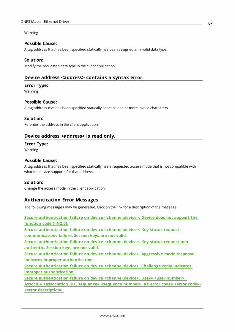
DNP3 Master Ethernet Driver
Warning
Possible Cause:A tag address that has been specified statically has been assigned an invalid data type.
Solution:Modify the requested data type in the client application.
Device address <address> contains a syntax error.Error Type:Warning
Possible Cause:A tag address that has been specified statically contains one or more invalid characters.
Solution:Re-enter the address in the client application.
Device address <address> is read only.Error Type:Warning
Possible Cause:A tag address that has been specified statically has a requested access mode that is not compatible withwhat the device supports for that address.
Solution:Change the access mode in the client application.
Authentication Error MessagesThe following messages may be generated. Click on the link for a description of the message.
Secure authentication failure on device <channel.device>. Device does not support thefunction code (IIN2.0).Secure authentication failure on device <channel.device>. Key status requestcommunications failure. Session keys are not valid.Secure authentication failure on device <channel.device>. Key status request non-authentic. Session keys are not valid.Secure authentication failure on device <channel.device>. Aggressive mode responseindicates improper authentication.Secure authentication failure on device <channel.device>. Challenge reply indicatesimproper authentication.Secure authentication failure on device <channel.device>. User= <user number>,AssocID= <association ID>, sequence= <sequence number>. RX error code= <error code>-<error description>.
www.ptc.com
87

DNP3 Master Ethernet Driver
Secure authentication failure on device <channel.device>. User= <user number>,AssocID= <association ID>, sequence= <sequence number>. TX error code= <error code>-<error description>.Secure authentication failure on device <device>. Key status request response statuscode: <status code>.
Secure authentication failure on device <channel.device>. Device does notsupport the function code (IIN2.0).Error Type:Warning
Possible Cause:The device is not configured to support authentication.
Solution:Either disabled the "Authentication" property in device properties or enable authentication on the device.
Secure authentication failure on device <channel.device>. Key StatusRequest communications failure. Session keys are not valid.Error Type:Warning
Possible Cause:
1. The master and slave are not configured to match.
2. Either the master or the slave restarted, and the other is expecting a different session key.
Solution:
1. Ensure that the User Number/Update Key pairs on the master match those in the device.
2. Correct any invalid settings (such as KeyWrap Algorithm). Then, wait for the master to issue the keychange request.
Secure authentication failure on device <channel.device>. Key StatusRequest non-authentic. Session Keys are not valid.Error Type:Warning
Possible Cause:The Update Keys do not match or there is another issue with encryption configuration.
Solution:Correct the invalid Update Key for the current User Number.
www.ptc.com
88

DNP3 Master Ethernet Driver
Secure authentication failure on device <channel.device>. AggressiveMode Response indicates improper authentication.Error Type:Warning
Possible Cause:The Update Keys do not match or there is another issue with encryption configuration.
Solution:Correct the invalid Update Key for the current User Number.
Secure authentication failure on device <channel.device>. Challenge Replyindicates improper authentication.Error Type:Warning
Possible Cause:The Update Keys do not match or there is another issue with encryption configuration.
Solution:Correct the invalid Update Key for the current User Number.
Note:The slave rejected the critical request.
Secure authentication failure on device <channel.device>. User= <UserNumber>, AssocID= <Association ID>, Sequence= <Sequence Number>. RXError Code= <error code>-<error description>.Error Type:Warning
Possible Cause:An error occurred when receiving a message.
Solution:
www.ptc.com
89

DNP3 Master Ethernet Driver
1. To determine the solution, refer to the code's error description.
Code Number Description
1 Invalid Information
2 Unexpected Reply
3 No Reply
4 Aggressive Mode Not Supported
5 HMAC Algorithm Not Supported
6 Key Wrap Algorithm Not Supported
7 User Access Denied
8 Key Change Request Denied
9 Invalid Signature
10 Invalid Certification
11 Unknown User
128..255 Vendor Specific
2. When a User Number is provided, it can be used to confirm that the User Number and Update Keymatch in the master and slave.
3. When an Association ID is provided, it can be used to uniquely identify the association between themaster and the slave on which the error occurred. This ID may correspond to different combinationsof DNP addresses, IP addresses, and port numbers (or identifiers on the master and the slave).
4. When a Sequence Number is provided, it can be used to determine which request (such as aChallenge or Key Change) had the authentication failure.
Secure authentication failure on device <channel.device>. User= <UserNumber>, AssocID= <Association ID>, Sequence= <Sequence Number>. TXError Code= <error code>-<error description>.Error Type:Warning
Possible Cause:An error occurred when transmitting a message.
Solution:
www.ptc.com
90

DNP3 Master Ethernet Driver
1. To determine the solution, refer to the code's error description.
Code Number Description
1 Invalid Information
2 Unexpected Reply
3 No Reply
4 Aggressive Mode Not Supported
5 HMAC Algorithm Not Supported
6 Key Wrap Algorithm Not Supported
7 User Access Denied
8 Key Change Request Denied
9 Invalid Signature
10 Invalid Certification
11 Unknown User
128..255 Vendor Specific
2. When a User Number is provided, it can be used to confirm that the User Number and Update Keymatch in the master and slave.
3. When an Association ID is provided, it can be used to uniquely identify the association between themaster and the slave on which the error occurred. This ID may correspond to different combinationsof DNP addresses, IP addresses, and port numbers (or identifiers on the master and the slave).
4. When a Sequence Number is provided, it can be used to determine which request (such as aChallenge or Key Change) had the authentication failure.
Secure authentication failure on device <device>. Key Status Requestresponse status code: <status code>.Error Type:Warning
Possible Cause:An invalid status code was returned in the Key Status Request response from the slave.
Solution:The status code returned in the error message describes the status of the two Session Keys as known by theslave. If the status code is 0 ("not used") or 5-255 ("reserved for future use"), determine why the slave isresponding with an unsupported status code in the object group 120 variation 5 response.
Automatic Tag Database Generation Error MessagesThe following messages may be generated. Click on the link for a description of the message.
Unable to add data set <data set index> on device <device name>. Data set has <numberof elements> elements. The maximum number of elements allowed is <max. elements>.Unable to generate a tag database for device <device>. Channel is not open.
www.ptc.com
91
DNP3 Master Ethernet Driver
Unable to generate a tag database for device <device>. Session is not open.Unable to generate a tag database for device <driver>. The device is not responding.Unable to read device attribute set <set number>. No tags added on device <device>.
Unable to add data set <data set index> on device <device name>. Dataset has <number of elements> elements. The maximum number ofelements allowed is <max. elements>.Error Type:Informational
Possible Cause:The data set at the specified index has more than the maximum number of elements allowed.
Solution:Reduce the data set's number of elements.
Unable to generate a tag database for device <device>. Channel is notopen.Error Type:Warning
Possible Cause:The driver was unable to initialize the communication stack.
Solution:Reinitialize the driver by right-clicking on the Administrationmenu and then selecting Reinitialize. If theproblem persists, restart the master.
Unable to generate a tag database for device <device>. Session is notopen.Error Type:Warning
Possible Cause:The driver was unable to initialize the communication stack.
Solution:Reinitialize the driver by right-clicking on the Administrationmenu and then selecting Reinitialize. If theproblem persists, restart the master.
Unable to generate a tag database for device <driver>. The device is notresponding.Error Type:Warning
www.ptc.com
92

DNP3 Master Ethernet Driver
Possible Cause:
1. The Ethernet connection between the device and the Host PC is broken.
2. The communication parameters for the Ethernet connection are incorrect.
3. The named device may have been assigned an incorrect Network ID.
4. A device on the channel is unresponsive, due to improper timing settings or a brokencommunications link.
5. There are multiple channels using DNS host names that resolve to the same IP address.
Solution:
1. Verify the cabling between the DNPmaster and the DNP slave device.
2. Verify that the specified communications parameters match those of the device.
3. Verify that the Network ID given to the named device matches that of the actual device.
4. Locate the unresponsive device and then correct the timing settings or fix the brokencommunications link.
5. Ensure that all channels are using a unique destination host.
Unable to read device attribute set <set number>. No tags added ondevice <device>.Error Type:Warning
Possible Cause:The device attribute set specified does not exist in the device.
Solution:Disable "Standard Device Attributes" and/or "User-Defined Device Attributes" in the Tag Import group.
Device Status MessagesThe following messages may be generated. Click on the link for a description of the message.
<item description> on device <device> has been auto-demoted.<item description> on device <device> has been auto-promoted to determine if it can becompleted.Added <tag count> data set tag(s).Data set write of value <value to be written> pending on tag address <address> ondevice <device>.Device <device> does not support the LAN time sync style record current time functioncode 24 .Device <device> does not support the LAN time sync style write to object group 50,variation 3.Device <device> indicated an event buffer overflow (IIN 2.3).Device <device> indicated it restarted (IIN 1.7).
www.ptc.com
93
DNP3 Master Ethernet Driver
Device <device> initialization completed.Device <device> requested time synchronization (IIN 1.4).Device <device> restarting.Device <device name> is not responding.Failed to resolve destination host <host name> on channel <channel name>.The keep-alive interval with UDP protocol on device <device> was overridden.Reached max. events per point for object group <object group> Point <data index> ondevice <device>.Request failed on device <device>. Device does not support the function code (IIN2.0).Request to enable unsolicited messaging failed on device <device>.Unable to bind to local address (IP: xxx.xxx.xxx.xxx, Source Port: x).Unable to read point(s) <OBJ.VAR.IDX> on device <device>. Failed to initializecommunication stack.Unable to read point(s) <OBJ.VAR.IDX> on device <device>. Internal Error occurred.Unable to read point(s) <OBJ.VAR.IDX – OBJ.VAR.IDX> on device <device>. Failed toinitialize communication stack.Unable to read point(s) <OBJ.VAR.IDX – OBJ.VAR.IDX> on device <device>. Internal erroroccurred.Unable to read tag <tag address> on device <device>. Device indicates one or moreexception conditions (DNP flags byte=<hexadecimal byte> - <DNP flag exception list.Unable to receive response from device <device> within timeout. Either the request orresponse could not be completed or the response is invalid.Unable to write to address <address> on device <device>. Failed to initializecommunication stack.Unable to write to address <address> on device <device>. Internal error occurred.Write complete to data set <index> on device <device>.
<Item description> on device <device> has been auto-demoted.Error Type:Warning
Possible Cause:The device continues to set an IIN bit, which requires the master to do something (such as timesynchronization or clear the device restart bit); however, the device is rejecting the master's attempts to doso. This is possibly due to an issue with the authentication settings. When a number of successive cycles ofrequest timeouts and retries have occurred, the master stops trying for a period of time.
Solution:Confirm that the authentication settings specified in the master match those specified in the slave.
<Item description> on device <device> has been auto-promoted todetermine if it can be completed.Error Type:Warning
www.ptc.com
94

DNP3 Master Ethernet Driver
Possible Cause:A request that was previously demoted has been promoted so that the master can try to resend the request.
Solution:If the request is successful, nothing needs to be done. If the item continues to be demoted, ensure that theauthentication settings are correct.
Added <tag count> data set tag(s).Error Type:Informational
Possible Cause:If the added tag count for Data Set tags is 0, possible causes may be as follows:
1. There are no data sets defined in the slave.
2. The slave has a mismatched configuration; that is, it may be reporting that it has more prototypes ordescriptors than actually have elements defined. When the master requests the prototype ordescriptor definition, the slave then responds with a property error because it doesn’t havedefinitions for all of them.
Solution:
1. Either define the data set descriptors in the slave or disabled the Data Set property in Tag Import.
2. Correct the slave so that it reports the actual number of prototypes and descriptors that haveelements defined.
Data Set write of value <value to be written> pending on tag address<address> on device <device>.Error Type:Informational
Possible Cause:A write occurred to a tag that references a data set element. The value is not displayed in the tag value, butis pending a write to the data set.
Solution:The data set write is complete when a data set tag with the sub-type .Set has a Boolean True written to it.
Device <device> does not support the LAN Time Sync Style Record CurrentTime Function Code 24.Error Type:Warning
Possible Cause:The device does not support function code 24 - LAN (which is the specified time synchronizationmethod).
www.ptc.com
95

DNP3 Master Ethernet Driver
Solution:InDevice Properties | Communications, change the time synchronization setting to Serial.
Note:Time synchronization is successful despite the error message. To prevent the error message fromoccurring, change the setting as described above.
Device <device> does not support the LAN Time Sync Style write to objectgroup 50, variation 3.Error Type:Warning
Possible Cause:The device does not support a write to object group 50, variation 3, which is used in the second part of theLAN time synchronizationmethod.
Solution:To prevent the error message from occurring, openDevice Properties and then select theCommunications tab. In Time Sync Style, select Serial.
Note:Time synchronization is successful despite the error message.
Device <device> indicated an event buffer overflow (IIN 2.3).Error Type:Warning
Possible Cause:A response from the device included IIN bytes along with the bit set, indicating that an event buffer overflowcondition exists. At least one unconfirmed event was lost because the event buffers did not have enoughroom to store the information.
Solution:
1. If many events occur between event polls (and the bit is being set by the slave) decrease the eventpoll interval to keep the buffer size small.
2. To avoid logging unnecessary events, adjust the analog point deadband.
See Also:Event Playback
Device <device> indicated it restarted (IIN 1.7).Error Type:Informational
Possible Cause:A response from the device included IIN bytes along with the bit set. This indicates that the device restarted.
www.ptc.com
96

DNP3 Master Ethernet Driver
Solution:N/A
Device <device> initialization completed.Error Type:Informational
Possible Cause:
1. The master has successfully communicated with the device, and the following requests havesuccessfully completed (if configured):
l Integrity poll on restart.
l Data set change on startup.
l Enable unsolicited messages.
l Disable unsolicited messages.
2. When this message repeats frequently in the Event Log, it indicates that the master is repeatedlyrestarting. This may occur when channel serialization is in use, and the master receives a requestfrom the slave when it does not have the channel token. As such, the slave does not receive aresponse in the specified time and closes the socket.
Solution:
1. N/A
2. Determine why the master is restarting, and then correct the setup. If it is because the slave issending a request (such as a Link Status request, a Keep Alive request, or an unsolicited message)while channel serialization is in use, then the slave should be reconfigured to disable the requests orto increase the timeout (so it does not close the socket).
Device <device> requested time synchronization (IIN 1.4).Error Type:Informational
Possible Cause:A response from the device included IIN bytes along with the bit set. This indicates that the device requirestime synchronization from the master.
Solution:N/A
Device <device> is restarting.Error Type:Information
Possible Cause:
www.ptc.com
97

DNP3 Master Ethernet Driver
The client wrote a "1" to a Warmrestart or Coldrestart tag.
Solution:N/A
Device <device name> is not responding.Error Type:Serious
Possible Cause:
1. The Ethernet connection between the device and the Host PC is broken.
2. The communications parameters for the Ethernet connection are incorrect.
3. The named device may have been assigned an incorrect network ID.
4. A device on the channel is unresponsive, due to improper timing settings or a brokencommunications link.
5. There are multiple channels using DNS host names that resolve to the same IP address.
6. The response from the device took longer to receive than the amount of time specified in the"Request Timeout" device setting.
Solution:
1. Verify the cabling between the DNPmaster and the DNP slave device.
2. Verify that the specified communications parameters match those of the device.
3. Verify that the network ID given to the named device matches that of the actual device.
4. Locate the unresponsive device and then correct the timing settings or fix the brokencommunications link.
5. Ensure that all channels are using a unique Destination Host.
6. Increase the Request Timeout setting so that the entire response can be handled.
See Also:Timing and Other ConsiderationsCommunications
Failed to resolve destination host <host name> on channel <channelname>.Error Type:Fatal
Possible Cause:The channel has been configured to use a DNS host name instead of an IP address. The server cannotresolve the host name to an IP address.
Solution:
www.ptc.com
98

DNP3 Master Ethernet Driver
Ensure that the outstation device is online and registered with the domain.
The Keep-Alive Interval with UDP Protocol on device <device> wasoverridden.Error Type:Warning
Possible Cause:The XML project file contains a value for the Keep-Alive Interval that is not 0, and the channel protocol is setto UDP.
Solution:Change the Keep-Alive Interval in the XML project to 0. Alternatively, change the channel protocol to TCP.
Reached max. events per point for object group <object group> point<data index> on device <device>.Error Type:Warning
Possible Cause:At least one unconfirmed event was lost because the event buffers did not have enough room to store theinformation.
Reasons:
1. The value specified for the Max. Events Per Point parameter is too small to receive all of the eventswithout discarding data.
2. The event poll intervals are too large.
3. The slave is logging unnecessary events (such as changes in a floating value).
Solution:
1. Determine the buffer size allowed in the slave, and then set the max. events per point parameter tothe same value (or larger). This driver allows 10000 events per point. The default setting is 100.
2. If many events occur between event polls (and the max. events per point is reached) decrease theevent poll interval to keep the buffer size small.
3. To avoid logging unnecessary events, adjust the analog point deadband.
See Also:Event Playback
Request failed on device <device>. Device does not support the functioncode (IIN2.0).Error Type:Warning
www.ptc.com
99

DNP3 Master Ethernet Driver
Possible Cause:The device returned IIN bytes in the response with the "Function code not supported" bit set. This indicatesthat the device does not support the function code sent by the master in the request.
Solution:In Channel Diagnostics, check the TX entry that has a similar timestamp as the error in the Event Log todetermine which function code the device is not supporting. The solution depends on the function code.
Note:For example, if the device should support the "Enable unsolicited responses" (0x14) function code or the"Disable unsolicited responses" (0x15) function code, correct the configuration in the device. If the deviceshould not accept the function codes 0x14 or 0x15, change the Class 1, 2, and 3 Unsolicited Mode in deviceproperties to Automatic. For more information on specific function code error messages, refer to ErrorDescriptions.
Request to enable unsolicited messaging failed on device <device>.Error Type:Warning
Possible Cause:The device rejected a request to enable unsolicited messages on start.
1. The device may not be configured to allow the master to modify its unsolicited settings.
2. There is an issue with the authentication settings.
Solution:
1. Check how unsolicited or spontaneous messaging is configured in the device. If it does not allow themaster to configure unsolicited settings, change the unsolicited modes for each class to Automatic inthe master's Unsolicited group in device properties.
2. Confirm that the authentication settings specified in the master match those specified in the slave.
Unable to bind to local address (IP: xxx.xxx.xxx.xxx, Source Port: x).Error Type:Serious
Possible Cause:
1. More than one channel has been configured to use the same network adapter and source port.
2. Another application is running on the system that has already acquired the indicated networkadapter and source port for exclusive use.
Solution:
1. Select a different local IP address or source port for one of the repeating channels. The computermay also need to be multi-homed.
www.ptc.com
100
DNP3 Master Ethernet Driver
2. Close the other application.
Unable to read point(s) <OBJ.VAR.IDX> on device <device>. Failed toinitialize communication stack.Error Type:Fatal
Possible Cause:The driver was unable to initialize the communication stack.
Solution:Reinitialize the driver by right-clicking on the Administrationmenu and selecting Reinitialize. If the problempersists, restart the master.
Unable to read point(s) <OBJ.VAR.IDX> on device <device>. Internal Erroroccurred.Error Type:Fatal
Possible Cause:An internal error occurred within the driver.
Solution:The driver may recover on its own. If the problem persists, restart the master.
Unable to read point(s) <OBJ.VAR.IDX – OBJ.VAR.IDX> on device <device>.Failed to initialize communication stack.Error Type:Fatal
Possible Cause:The driver was unable to initialize the communication stack.
Solution:Reinitialize the driver by right-clicking on the Administrationmenu and selecting Reinitialize. If the problempersists, restart the master.
Unable to read point(s) <OBJ.VAR.IDX – OBJ.VAR.IDX> on device <device>.Internal error occurred.Error Type:Fatal
Possible Cause:An internal error occurred within the driver.
www.ptc.com
101
DNP3 Master Ethernet Driver
Solution:The driver may recover on its own. If the problem persists, restart the master.
Unable to read tag <tag address> on device <device>. Device indicates oneor more exception conditions (DNP flags byte=<hexadecimal byte> - <DNPflag exception list).Error Type:Warning
Possible Cause:The device returned the data point DNP flag byte with either the Online bit cleared or with one or more ofthe exception bits set.
Solution:For a list of flag bits that are specific to the object group, refer to the "DNP Object Flag Definitions" subtopiclocated in the object group's address descriptions. For more information on a particular exception and howto clear it, refer to the device's documentation.
Unable to receive response from device <device> within timeout. Eitherthe request or response could not be completed or the response is invalid.Error Type:Warning
Possible Cause:
1. The response timeout is too short to allow the slave's integrity or event poll response to complete intime. The slave may be returning a large number of points, but the timeout elapsed before the datacould be received.
2. There is an issue with the authentication settings.
3. The data set exchange objects 213 and 215 are unknown to the device during initialization, causing itto be unable to complete.
4. The connection between the device and the host PC was interrupted while receiving the response.
Solution:
1. If the slave has been configured to return a large number of points (such as during a class 0 poll)change the channel's Response Timeout to a value that allow the response to complete successfully.
2. Confirm that the authentication settings in the master match those in the slave.
3. If data sets are not in use, disable the Exchange Data Sets property in the Advanced tab of deviceproperties.
4. Verify the cabling between the DNPmaster and the DNP slave device.
Notes:
www.ptc.com
102
DNP3 Master Ethernet Driver
1. The channel's response timeout should be as accurate as possible, because it is also the time thatthe driver waits before reporting that the device is not responding.
2. The device request timeout should be greater than the channel response timeout.
See Also:Timing and Other ConsiderationsCommunications
Unable to write to address <address> on device <device>. Failed toinitialize communication stack.Error Type:Fatal
Possible Cause:The driver was unable to initialize the communication stack.
Solution:Reinitialize the driver by right-clicking on the Administrationmenu and selecting Reinitialize. If the problempersists, restart the master.
Unable to write to address <address> on device <device>. Internal erroroccurred.Error Type:Fatal
Possible Cause:An internal error occurred within the driver.
Solution:The driver may recover on its own. If the problem persists, restart the master.
Write complete to data set <index> on device <device>.Error Type:Informational
Possible Cause:A Data Set tag with the sub-type .Set had a Boolean True written to it while pending writes existed.
Solution:The pending data set writes have been sent to the device, although they may not have been successful.
Note:This message indicates that the write completed and the pending data has been cleared.
www.ptc.com
103
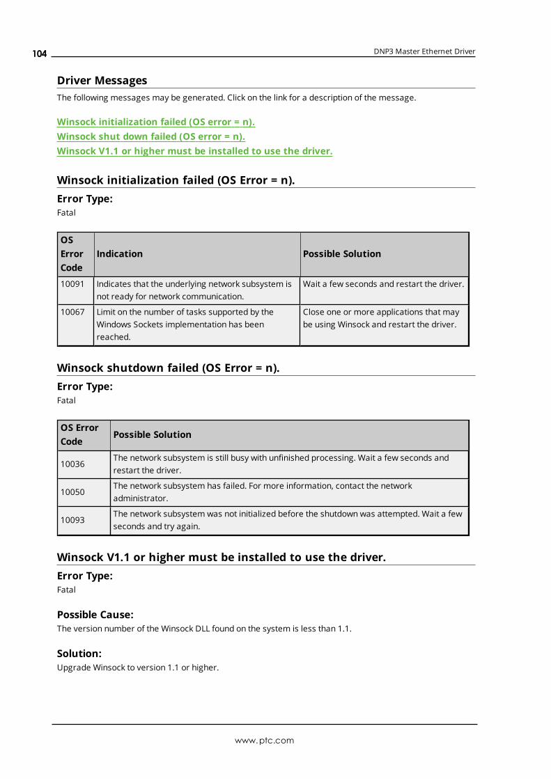
DNP3 Master Ethernet Driver
Driver MessagesThe following messages may be generated. Click on the link for a description of the message.
Winsock initialization failed (OS error = n).Winsock shut down failed (OS error = n).Winsock V1.1 or higher must be installed to use the driver.
Winsock initialization failed (OS Error = n).Error Type:Fatal
OSErrorCode
Indication Possible Solution
10091 Indicates that the underlying network subsystem isnot ready for network communication.
Wait a few seconds and restart the driver.
10067 Limit on the number of tasks supported by theWindows Sockets implementation has beenreached.
Close one or more applications that maybe using Winsock and restart the driver.
Winsock shutdown failed (OS Error = n).Error Type:Fatal
OS ErrorCode
Possible Solution
10036The network subsystem is still busy with unfinished processing. Wait a few seconds andrestart the driver.
10050The network subsystem has failed. For more information, contact the networkadministrator.
10093The network subsystem was not initialized before the shutdown was attempted. Wait a fewseconds and try again.
Winsock V1.1 or higher must be installed to use the driver.Error Type:Fatal
Possible Cause:The version number of the Winsock DLL found on the system is less than 1.1.
Solution:Upgrade Winsock to version 1.1 or higher.
www.ptc.com
104
DNP3 Master Ethernet Driver
DNP-Specific MessagesThe following messages may be generated. Click on the link for a description of the message.
Read ErrorsWrite Errors
Read ErrorsThe following error/warning messages may be generated. Click on the link for a description of the message.
The returned value for tag address <tag address> in device <device name> has a lengthof zero. The tag value cannot be set.The returned value of <date returned value> for tag address <address> in device<device> is invalid for the <data type> tag.The returned value of <returned numeric value> for tag address <address> in device<device> is invalid for the <data type> tag data type.The returned value of <returned numeric value> for tag address <address> in device<device> is out of range for the <data type> tag data type.The returned value of <returned string value> for tag address <address> in device<device> is invalid for the <data type> tag data type.Unable to read point(s) <OBJ.VAR.IDX> on device <device>. An abnormal condition existsin the device (IIN1.6).Unable to read point(s) <OBJ.VAR.IDX> on device <device>. Device detected corruptconfiguration (IIN2.5).Unable to read point(s) <OBJ.VAR.IDX> on device <device>. Device does not support apoint in the range or other parameter error (IIN2.2).Unable to read point(s) <OBJ.VAR.IDX> on device <device>. Device does not supportrequested operation for objects in the request (IIN2.1).Unable to read point(s) <OBJ.VAR.IDX> on device <device>. Device does not support thefunction code (IIN2.0).Unable to read point(s) <OBJ.VAR.IDX> on device <device>. Device reports that someoutput points are in local mode (IIN1.5).Unable to read point(s) <OBJ.VAR.IDX> on device <device>. Device reports that theoperation is already executing (IIN2.4).Unable to read point(s) <OBJ.VAR.IDX> on device <device>. Session shutting down orduplicate request.Unable to read point(s) <OBJ.VAR.IDX> on device <device>. Unable to receive responsefrom device <device> within timeout. Either the request or response could not becompleted or the response is invalid.Unable to read point(s) <OBJ.VAR.IDX> on device <device>. Unrecognized object returnedin response.Unable to read point(s) <OBJ.VAR.IDX – OBJ.VAR.IDX> on device <device>. An abnormalcondition exists in the device (IIN1.6).Unable to read point(s) <OBJ.VAR.IDX – OBJ.VAR.IDX> on device <device>. Device detectedcorrupt configuration (IIN2.5).
www.ptc.com
105

DNP3 Master Ethernet Driver
Unable to read point(s) <OBJ.VAR.IDX – OBJ.VAR.IDX> on device <device>. Device does notsupport a point in the range or other parameter error (IIN2.2).Unable to read point(s) <OBJ.VAR.IDX – OBJ.VAR.IDX> on device <device>. Device does notsupport requested operation for objects in the request (IIN2.1).Unable to read point(s) <OBJ.VAR.IDX – OBJ.VAR.IDX> on device <device>. Device doesnot support the function code (IIN2.0).Unable to read point(s) <OBJ.VAR.IDX – OBJ.VAR.IDX> on device <device>. Device reportsthat some output points are in local mode (IIN1.5).Unable to read point(s) <OBJ.VAR.IDX – OBJ.VAR.IDX> on device <device>. Device reportsthat the operation is already executing (IIN2.4).Unable to read point(s) <OBJ.VAR.IDX – OBJ.VAR.IDX> on device <device>. Sessionshutting down or duplicate request.Unable to read point(s) <OBJ.VAR.IDX - OBJ.VAR.IDX> on device <device>. Unable toreceive response from device <device> within timeout. Either the request or responsecould not be completed or the response is invalid.Unable to read point(s) <OBJ.VAR.IDX – OBJ.VAR.IDX> on device <device>. Unrecognizedobject returned in response.Unable to read set <set index> of object group <object group> on device <device>. Anabnormal condition exists in the device (IIN1.6).Unable to read set <set index> of object group <object group> on device <device>. Devicedetected corrupt configuration (IIN2.5).Unable to read set <set index> of object group <object group> on device <device>. Devicedoes not support a point in the range or other parameter error (IIN2.2).Unable to read set <set index> of object group <object group> on device <device>. Devicedoes not support requested operation for objects in the request (IIN2.1).Unable to read set <set index> of object group <object group> on device <device>. Devicedoes not support the function code (IIN2.0).Unable to read set <set index> of object group <object group> on device <device>. Devicereports that some output points are in local mode (IIN1.5).Unable to read set <set index> of object group <object group> on device <device>. Devicereports that the operation is already executing (IIN2.4).Unable to read set <set index> of object group <object group> on device <device>.Session shutting down or duplicate request.Unable to read set <set index> of object group <object group> on device <device>.Unrecognized object returned in response.Unable to read tag address <address> on device <device>. Element Index <variation> isnot defined in data set <index>.Unable to read tag address <address> on device <device>. No definition for Data Set<index>.Unable to read tag address <address> on device <device>. Response missing data.
The returned value for tag address <tag address> in device <device name>has a length of zero. The tag value cannot be set.Error Type:
www.ptc.com
106

DNP3 Master Ethernet Driver
Warning
Possible Cause:The tag has addressed an element that has been defined in the slave with a data length of zero.
Solution:Increase the data length to an appropriate value for the data type.
The returned value of <date returned value> for tag address <address> indevice <device> is invalid for the <data type> tag data type.Error Type:Warning
Possible Cause:The device has configured the device attribute variation or data set element as a Date value, but the tag'sdata type is not Date.
Solution:Change the tag's data type to Date.
The returned value of <returned numeric value> for tag address <address>in device <device> is invalid for the <data type> tag data type.Error Type:Warning
Possible Cause:The device has configured the device attribute variation or data set element as a numeric value, but thetag's data type is String.
Solution:Change the tag's data type to the appropriate numeric type.
The returned value of <returned numeric value> for tag address <address>in device <device> is out of range for the <data type> tag data type.Error Type:Warning
Possible Cause:The device has configured the device attribute variation or data set element as a data type that is out ofrange for the data type of the tag.
Solution:Change the tag's data type to match the data type configured in the slave.
www.ptc.com
107

DNP3 Master Ethernet Driver
The returned value of <returned string value> for tag address <address> indevice <device> is invalid for the <data type> tag data type.Error Type:Warning
Possible Cause:The device has configured the device attribute variation or data set element as a string, but the tag's datatype is numeric.
Solution:Change the tag's data type to string.
Unable to read point(s) <OBJ.VAR.IDX> on device <device>. An abnormalcondition exists in the device (IIN1.6).Error Type:Warning
Possible Cause:An abnormal condition has occurred that is specific to the device.
Solution:Resolve any hardware issues found in the slave.
Unable to read point(s) <OBJ.VAR.IDX> on device <device>. Device detectedcorrupt configuration (IIN2.5).Error Type:Warning
Possible Cause:The device has detected that its configuration is corrupt.
Solution:Reconfigure the slave.
Unable to read point(s) <OBJ.VAR.IDX> on device <device>. Device does notsupport a point in the range or other parameter error (IIN2.2).Error Type:Warning
Possible Cause:
1. The device does not support a point in the specified range.
2. The device does not understand the parameters sent in the request.
Solution:Change the point(s) to one supported by the slave.
www.ptc.com
108

DNP3 Master Ethernet Driver
Unable to read point(s) <OBJ.VAR.IDX> on device <device>. Device does notsupport requested operation for objects in the request (IIN2.1).Error Type:Warning
Possible Cause:The device does not support the requested operation for the objects in the request.
Solution:Verify that the slave supports the requested operation.
Unable to read point(s) <OBJ.VAR.IDX> on device <device>. Device does notsupport the function code (IIN2.0).Error Type:Warning
Possible Cause:The device does not support the function code.
Solution:None.
Note:For more information, refer to the device's documentation.
Unable to read point(s) <OBJ.VAR.IDX> on device <device>. Device reportsthat some output points are in local mode (IIN1.5).Error Type:Warning
Possible Cause:Some output points are in local mode.
Solution:Correct the mode in the slave's configuration.
Note:For more information, refer to the device's documentation.
Unable to read point(s) <OBJ.VAR.IDX> on device <device>. Device reportsthat the operation is already executing (IIN2.4).Error Type:Warning
Possible Cause:
www.ptc.com
109

DNP3 Master Ethernet Driver
The specified point is being acted upon by another client.
Solution:
1. Stop the other client from acting upon the points.
2. Delay the operation of the points.
Unable to read point(s) <OBJ.VAR.IDX> on device <device>. Sessionshutting down or duplicate request.Error Type:Warning
Possible Cause:The client disconnected while a transaction was in progress.
Solution:Confirm that the connection between the master and the slave is okay.
Unable to read point(s) <OBJ.VAR.IDX> on device <device>. Unable toreceive response from device <device> within timeout. Either the requestor response could not be completed or the response is invalid.Error Type:Warning
Possible Cause:
1. The response timeout is too short to allow the read to complete in time. The slave may have returneda large number of points in the response, but the timeout elapsed before the data was received.
2. There is an issue with the authentication settings.
Solution:
1. If the slave is returning a large number of points in the response, change the channel's ResponseTimeout to a value that allows the response to complete successfully.
2. Confirm that the authentication settings in the master match those in the slave.
Notes:
1. The channel's response timeout should be as accurate as possible, because it is also the time thatthe driver waits before reporting that the device is not responding.
2. The device's request timeout should be greater than the channel's response timeout.
See Also:Timing and Other ConsiderationsCommunications
www.ptc.com
110

DNP3 Master Ethernet Driver
Unable to read point(s) <OBJ.VAR.IDX> on device <device>. Unrecognizedobject returned in response.Error Type:Warning
Possible Cause:The response from the slave contains something that is unrecognized. This does not include function codesor objects, which have their own error messages. For more information, refer to the list below.
1. The qualifier may be incorrect or unsupported.
2. The length of the response may not match the length that was expected.
3. For object group 87 - data sets reads, this error may mean that more elements are in the data setthan are allowed.
Solution:
1. Review the channel diagnostics to find which qualifier is being used in the response from the slave.Then, check the object's implementation table to see if that qualifier is supported. If it is not,determine whether the slave can be configured to use a supported qualifier for the object or functioncode.
2. Review the channel diagnostics to find if the length reported in the response matches the number ofbytes actually sent from the slave or if the checksum was calculated correctly. Then, determinewhether a faulty connection is causing the missing bytes and correct as necessary.
3. If the tag is a data set tag of object group 87 and the data set has more than 32 elements, reduce thenumber of elements in the data set on the slave.
Unable to read point(s) <OBJ.VAR.IDX – OBJ.VAR.IDX> on device <device>.An abnormal condition exists in the device (IIN1.6).Error Type:Warning
Possible Cause:An abnormal condition has occurred that is specific to the device.
Solution:Resolve any hardware issues found in the slave.
Unable to read point(s) <OBJ.VAR.IDX – OBJ.VAR.IDX> on device <device>.Device detected corrupt configuration (IIN2.5).Error Type:Warning
Possible Cause:The device has detected that its configuration is corrupt.
www.ptc.com
111

DNP3 Master Ethernet Driver
Solution:Reconfigure the slave.
Unable to read point(s) <OBJ.VAR.IDX – OBJ.VAR.IDX> on device <device>.Device does not support a point in the range or other parameter error(IIN2.2).Error Type:Warning
Possible Cause:
1. The device does not support a point in the specified range.
2. The device does not understand the parameters sent in the request.
Solution:Change the points to ones supported by the slave.
Unable to read point(s) <OBJ.VAR.IDX – OBJ.VAR.IDX> on device <device>.Device does not support requested operation for objects in the request(IIN2.1).Error Type:Warning
Possible Cause:The device does not support the requested operation for the objects in the request.
Solution:Verify that the slave supports the requested operation.
Unable to read point(s) <OBJ.VAR.IDX – OBJ.VAR.IDX> on device <device>.Device does not support the function code (IIN2.0).Error Type:Warning
Possible Cause:The device does not support the function code.
Solution:None.
Note:For more information, refer to the device's documentation.
Unable to read point(s) <OBJ.VAR.IDX – OBJ.VAR.IDX> on device <device>.Device reports that some output points are in local mode (IIN1.5).Error Type:
www.ptc.com
112
DNP3 Master Ethernet Driver
Warning
Possible Cause:Some output points are in local mode.
Solution:Correct the mode in the slave's configuration.
Note:For more information, refer to the device's documentation.
Unable to read point(s) <OBJ.VAR.IDX – OBJ.VAR.IDX> on device <device>.Device reports that the operation is already executing (IIN2.4).Error Type:Warning
Possible Cause:The specified points are being acted upon by another client.
Solution:
1. Stop the other client from acting upon the points.
2. Delay the operation of the points.
Unable to read point(s) <OBJ.VAR.IDX – OBJ.VAR.IDX> on device <device>.Session shutting down or duplicate request.Error Type:Warning
Possible Cause:The client disconnected while a transaction was in progress.
Solution:Confirm that the connection between the master and the slave is okay.
Unable to read point(s) <OBJ.VAR.IDX - OBJ.VAR.IDX> on device <device>.Unable to receive response from device <device> within timeout. Eitherthe request or response could not be completed or the response is invalid.Error Type:Warning
Possible Cause:
1. The Response Timeout is too short to allow the read to complete in time. The slave may havereturned a large number of points in the response, but the timeout elapsed before the data was
www.ptc.com
113

DNP3 Master Ethernet Driver
received.
2. There is an issue with the authentication settings.
Solution:
1. If the slave is returning a large number of points in the response, change the channel's responsetimeout to a value that allows the response to complete successfully.
2. Confirm that the authentication settings in the master match those in the slave.
Notes:
1. The channel's response timeout should be as accurate as possible, because it is also the time thatthe driver waits before reporting that the device is not responding.
2. The device's request timeout should be greater than the channel's response timeout.
See Also:Timing and Other ConsiderationsCommunications
Unable to read point(s) <OBJ.VAR.IDX – OBJ.VAR.IDX> on device <device>.Unrecognized object returned in response.Error Type:Warning
Possible Cause:The slave does not support the read request.
Solution:Change the request to one supported by the slave.
Unable to read set <set index> of object group <object group> on device<device>. An abnormal condition exists in the device (IIN1.6).Error Type:Warning
Possible Cause:An abnormal condition has occurred that is specific to the device.
Solution:Resolve any hardware issues found in the slave.
Unable to read set <set index> of object group <object group> on device<device>. Device detected corrupt configuration (IIN2.5).Error Type:Warning
Possible Cause:
www.ptc.com
114
DNP3 Master Ethernet Driver
The device has detected that its configuration is corrupt.
Solution:Reconfigure the slave.
Unable to read set <set index> of object group <object group> on device<device>. Device does not support a point in the range or other parametererror (IIN2.2).Error Type:Warning
Possible Cause:
1. The device does not support a point in the specified range.
2. The device does not understand the parameters sent in the request.
Solution:Change the points to one supported by the slave.
Unable to read set <set index> of object group <object group> on device<device>. Device does not support requested operation for objects in therequest (IIN2.1).Error Type:Warning
Possible Cause:The device does not support the requested operation for the objects in the request.
Solution:Verify that the slave supports the requested operation.
Unable to read set <set index> of object group <object group> on device<device>. Device does not support the function code (IIN2.0).Error Type:Warning
Possible Cause:The device does not support the function code.
Solution:None.
Note:For more information, refer to the device's documentation.
www.ptc.com
115

DNP3 Master Ethernet Driver
Unable to read set <set index> of object group <object group> on device<device>. Device reports that some output points are in local mode(IIN1.5).Error Type:Warning
Possible Cause:Some output points are in local mode.
Solution:Correct the mode in the slave's configuration.
Note:For more information, refer to the device's documentation.
Unable to read set <set index> of object group <object group> on device<device>. Device reports that the operation is already executing (IIN2.4).Error Type:Warning
Possible Cause:The specified point is being acted upon by another client.
Solution:
1. Stop the other client from acting upon the points.
2. Delay the operation of the points.
Unable to read set <set index> of object group <object group> on device<device>. Session shutting down or duplicate request.Error Type:Warning
Possible Cause:The client disconnected while a transaction was in progress.
Solution:Confirm that the connection between the master and the slave is okay.
Unable to read set <set index> of object group <object group> on device<device>. Unrecognized object returned in response.Error Type:Warning
Possible Cause:
www.ptc.com
116

DNP3 Master Ethernet Driver
The response from the slave contains something that is unrecognized. This does not include function codesor objects, which have their own error messages. For more information, refer to the list below.
1. The qualifier may be incorrect or unsupported.
2. The length of the response may not match the length that was expected.
3. For object group 87 - Data Sets reads, this error may mean that more elements are in the data setthan are allowed.
Solution:
1. Review the channel diagnostics to find which qualifier is being used in the response from the slave.Then, check the object's implementation table to see if that qualifier is supported. If it is not,determine whether the slave can be configured to use a supported qualifier for the object or functioncode.
2. Review the channel diagnostics to find if the length reported in the response matches the number ofbytes actually sent from the slave, or if the checksum was calculated correctly. Then, determinewhether a faulty connection is causing the missing bytes and correct as necessary.
3. If the tag is a data set tag of object group 87 and the data set has more than 32 elements, reduce thenumber of elements in the data set on the slave.
Unable to read tag address <address> on device <device>. Element index<variation> is not defined in data set <index>.Error Type:Warning
Possible Cause:The slave does not define this element index within the data set.
Solution:
1. If the element index should be defined, correct the data set in the slave.
2. If the element index is invalid, correct the tag address in the project.
Unable to read tag address <address> on device <device>. No definition fordata set <index>.Error Type:Warning
Possible Cause:
1. A data set definition does not exist for the data set index of the .Value tag being read.
2. A data set exchange took place between the master and the slave. A new data set was then added inthe slave unknown to the master.
Solution:
www.ptc.com
117

DNP3 Master Ethernet Driver
1. Create the data set in the slave.
2. Initiate a data set exchange. To do so, click Device Properties | Tag Import and select Import Tags.Alternatively, restart the master.
Unable to read tag address <address> on device <device>. Responsemissing data.Error Type:Warning
Possible Cause:Although the response from the slave indicated success, data for one or more points in the requested rangewas not included in the response.
Solution:Confirm that the points are enabled in the slave.
Note:For example, if the tag references object group 87 - data sets, confirm that all data set elements areconfigured in the slave with the correct data type and length and that the data set characteristics arecorrectly configured.
Write ErrorsThe following error/warning messages may be generated. Click on the link for a description of the message.
Unable to write to address <address> on device <device>. Activate configuration-relatedstatus code <status code> - <description>.Unable to write to address <address> on device <device>. An abnormal condition existsin the device (IIN1.6).Unable to write to address <address> on device <device>. Channel response timeoutmust be between <min channel response timeout> and <max. channel responsetimeout>.Unable to write to address <address> on device <device>. Control-related status code<status code>Unable to write to address <address> on device <device>. Destination <destinationhost>:<destination port> already in use on channel <channel>.Unable to write to address <address> on device <device>. Destination port must bebetween <min. source port> and <max. source port>.Unable to write to address <address> on device <device>. Device detected corruptconfiguration (IIN2.5).Unable to write to address <address> on device <device>. Device does not support apoint in the range or other parameter error (IIN2.2).Unable to write to address <address> on device <device>. Device does not supportrequested operation for objects in the request (IIN2.1).
www.ptc.com
118

DNP3 Master Ethernet Driver
Unable to write to address <address> on device <device>. Device does not support thefunction code (IIN2.0).Unable to write to address <address> on device <device>. Device reports that someoutput points are in local mode (IIN1.5).Unable to write to address <address> on device <device>. Device reports that theoperation is already executing (IIN2.4).Unable to write to address <address> on device <device>. Device request timeout mustbe between <min value> and <max. value>.Unable to write to address <address> on device <device>. Element index <variation> isnot defined in data set <index>.Unable to write to address <address> on device <device>. Event poll interval must bebetween <min. value> and <max. value>.Unable to write to address <address> on device <device>. File name writes have beendisabled.Unable to write to address <address> on device <device>. Integrity poll interval must bebetween <min. value> and <max. value>.Unable to write to address <address> on device <device>. Master address <masteraddress> already in use as slave address on device <device>.Unable to write to address <address> on device <device>. Master address must bebetween <min master address> and <max. master address>.Unable to write to address <address> on device <device>. Master and slave addresscannot be the same.Unable to write to address <address> on device <device>. No definition for data set<index>.Unable to write to address <address> on device <device>. Protocol must be between<min protocol> and <max. protocol>.Unable to write to address <address> on device <device>. Select operate responseinvalid.Unable to write to address <address> on device <device>. Session shutting down orduplicate request.Unable to write to address <address> on device <device>. Slave address <slave address>already in use on Device <device>Unable to write to address <address> on device <device>. Slave address must be between<min slave address> and <max. slave address>.Unable to write to address <address> on device <device>. Source port must be between<min source port> and <max. source port>.Unable to write to address <address> on device <device>. Tag <data type> data type isincompatible with the data set element <data type> data type.Unable to write to address <address> on device <device>. Unable to receive responsefrom device <device> within timeout. Either the request or response could not becompleted or the response is invalid.Unable to write to address <address> on device <device>. Unrecognized object returnedin Response.Unable to write to address <address> on device <device>. Unsupported operation type.Unable to write to address <address> on device <device>. Unsupported trip-close code.
www.ptc.com
119

DNP3 Master Ethernet Driver
Unable to write to address <address> on device <device>. Write value specified is invalidor incomplete.
Unable to write to address <address> on device <device>. Activateconfiguration-related status code <status code> - <description>.Error Type:Warning
Possible Cause:The Activate Configuration Request that was sent to the slave contained an invalid object or specificationstring.
Solution:For information on a specific status code, refer to the table below.
StatusCode
Description
0No errors were detected in the corresponding request object.No errors were detected in the configuration data referenced by the corresponding requestobject.
1An error was detected in the request object. For example, the slave was unable to locate a filereferenced by a g70 file specification string, or the slave does not have a name referenced by ag110 octet string.
2 An error was detected in the configuration data referenced by the corresponding request data.
3 An error occurred that is not listed above.
4 The Activate Config object was not checked for errors.
Unable to write to address <address> on device <device>. An abnormalcondition exists in the device (IIN1.6).Error Type:Warning
Possible Cause:An abnormal condition has occurred that is specific to the device.
Solution:Resolve any hardware issues found in the slave.
Unable to write to address <address> on device <device>. Channelresponse timeout must be between <min channel response timeout> and<max. channel response timeout>.Error Type:Warning
Possible Cause:
www.ptc.com
120

DNP3 Master Ethernet Driver
The value is out of range.
Solution:Specify a value within the channel response timeout range of 100 to 3600000 milliseconds.
Unable to write to address <address> on device <device>. Control-relatedstatus code <status code>.Error Type:Warning
Possible Cause:
1. The value written to the .Operate sub-type was not understood by the DNP slave.
2. If the operate was successful but the feedback poll failed, the device reports status code 4.
Solution:For information on a specific code number, refer to the table below.
CodeNumber
IdentifierName
Description
0 Success Request accepted, initiated, or queued.
1 TimeoutRequest not accepted because the operate message was received after thearm timer timed out. The arm timer was started when the select operation forthe same point was received.
2 No_SelectRequest not accepted because no previous matching select request exists. Anoperate message was sent to activate an output that was not previously armedwith a matching select message.
3Format_Error
Request not accepted because there were formatting errors in the controlrequest (either select, operate, or direct operate).
4Not_Supported
1. Request not accepted because a control operation is not supported for thispoint.2. The device does not understand the feedback poll request for the latestvalue of all objects of an object group.
5Already_Active
Request not accepted because the control queue is full (or the point is alreadyactive).
6Hardware_Error
Request not accepted because of control hardware problems.
7 Local Request not accepted because the Local/Remote switch is in the Local position.
8Too_Many_Objs
Request not accepted because too many objects appeared in the samerequest.
9Not_Authorized
Request not accepted because of insufficient authorization.
10Automation_Inhibit
Request not accepted because it was prevented or inhibited by a localautomation process.
11Processing_Limited
Request not accepted because the device cannot process any more activitiesthan are presently in progress.
www.ptc.com
121

DNP3 Master Ethernet Driver
CodeNumber
IdentifierName
Description
12Out_Of_Range
Request not accepted because the value is outside the acceptable rangepermitted for this point.
13 to 125 Reserved Reserved for future use.
126Non_Participating
Sent in request messages indicating that the outstation neither issues norperforms the control operation.
127 Undefined Request not accepted due to an undefined reason.
Unable to write to address <address> on device <device>. Destination<destination host >:<destination port> already in use on channel<channel>.Error Type:Warning
Possible Cause:The destination host and the destination port specified are already in use.
Solution:Make sure that each channel in the server project has a unique destination host and destination portcombination.
Unable to write to address <address> on device <device>. Destination portmust be between <min. source port> and <max. source port>.Error Type:Warning
Possible Cause:The value is out of range.
Solution:Specify a value within the Destination Port range of 1 to 65535.
Unable to write to address <address> on device <device>. Device detectedcorrupt configuration (IIN2.5).Error Type:Warning
Possible Cause:The device has detected that its configuration is corrupt.
Solution:Reconfigure the slave.
www.ptc.com
122
DNP3 Master Ethernet Driver
Unable to write to address <address> on device <device>. Device does notsupport a point in the range or other parameter error (IIN2.2).Error Type:Warning
Possible Cause:
1. The device does not support a point in the specified range.
2. The device does not understand the parameters sent in the request.
Solution:Change the tag address to one supported by the slave.
Unable to write to address <address> on device <device>. Device does notsupport requested operation for objects in the request (IIN2.1).Error Type:Warning
Possible Cause:The device does not support the requested operation for the objects in the request.
Solution:Verify that the slave supports the requested operation.
Unable to write to address <address> on device <device>. Device does notsupport the function code (IIN2.0).Error Type:Warning
Possible Cause:The device does not support the function code.
Solution:None.
Note:For more information, refer to the device's documentation.
Unable to write to address <address> on device <device>. Device reportsthat some output points are in local mode (IIN1.5).Error Type:Warning
Possible Cause:Some output points are in local mode.
www.ptc.com
123
DNP3 Master Ethernet Driver
Solution:Correct the mode in the slave's configuration.
Note:For more information, refer to the device's documentation.
Unable to write to address <address> on device <device>. Device reportsthat the operation is already executing (IIN2.4).Error Type:Warning
Possible Cause:The specified address is being acted upon by another client.
Solution:
1. Stop the other client from acting upon the address.
2. Delay the operation of the address.
Unable to write to address <address> on device <device>. Device RequestTimeout must be between <min. value> and <max. value>.Error Type:Warning
Possible Cause:The value is out of range.
Solution:Specify a value within the device request timeout range of 0 to 3600000 seconds.
Unable to write to address <address> on device <device>. Element index<variation> is not defined in data set <index>.Error Type:Warning
Possible Cause:The slave does not define this element index within the data set.
Solution:
1. If the element index should be defined, correct the data set in the slave.
2. If the element index is invalid, correct the tag address in the project.
www.ptc.com
124

DNP3 Master Ethernet Driver
Unable to write to address <address> on device <device>. Event pollinterval must be between <min. value> and <max. value>.Error Type:Warning
Possible Cause:The value is out of range.
Solution:Specify a value within the Event Poll Interval range of 0 to 86400 seconds.
Unable to write to address <address> on device <device>. File name writeshave been disabled.Error Type:Warning
Possible Cause:An attempt to modify the value of a 70.<index>.LocalFileName tag or 70.<index>.RemoteFileName tag failedbecause the File Name Writes property was disabled in File Control (located in device properties).
Solution:Enable the File Name Writes property.
See Also:File Control
Unable to write to address <address> on device <device>. Integrity pollinterval must be between <min. value> and <max. value>.Error Type:Warning
Possible Cause:The value is out of range.
Solution:Specify a value within the Integrity Poll Interval range of 0 to 2592000 seconds.
Unable to write to address <address> on device <device>. Master address<master address> already in use as slave address on device <device>.Error Type:Warning
Possible Cause:The master address is already in use as a slave address on another device.
www.ptc.com
125

DNP3 Master Ethernet Driver
Solution:Specify a master address that is unique among all slave addresses in the channel.
Unable to write to address <address> on device <device>. Master addressmust be between <min. master address> and <max. master address>.Error Type:Warning
Possible Cause:The value is out of range.
Solution:Specify a value within the master address range of 0 to 65519.
Unable to write to address <address> on device <device>. Master and slaveaddress cannot be the same.Error Type:Warning
Possible Cause:The master address and slave address are the same.
Solution:Specify unique values for the master address and the slave address.
Unable to write to address <address> on device <device>. No definition fordata set <index>.Error Type:Warning
Possible Cause:
1. A data set definition does not exist for the data set index of the write tag.
2. A data set exchange took place between the master and the slave. A new data set was then added inthe slave unknown to the master.
Solution:
1. Create the data set in the slave.
2. Initiate a data set exchange. To do so, click Device Properties | Tag Import and then select ImportTags. Alternatively, restart the master.
Unable to write to address <address> on device <device>. Protocol must bebetween <min. protocol> and <max. protocol>.Error Type:Warning
www.ptc.com
126
DNP3 Master Ethernet Driver
Possible Cause:The value is out of range.
Solution:Specify a value that is allowed.
Note:The Protocol value is an enumerated type: a value of 0 corresponds to TCP/IP, and a value of 1 correspondsto UDP. No other values are allowed.
Unable to write to address <address> on device <device>. Select Operateresponse invalid.Error Type:Warning
Possible Cause:The device did not return an acceptable response to a Select then Operate request.
Solution:Verify that the slave is configured to operate on the point.
Unable to write to address <address> on device <device>. Session shuttingdown or duplicate request.Error Type:Warning
Possible Cause:The client disconnected while a transaction was in progress.
Solution:Confirm that the connection between the master and the slave is okay.
Unable to write to address <address> on device <device>. Slave address<slave address> already in use on device <device>.Error Type:Warning
Possible Cause:The slave address is already in use as a master address or slave address on another device in the channel.
Solution:Specify a slave address that is unique among all master addresses and slave addresses in the channel.
www.ptc.com
127

DNP3 Master Ethernet Driver
Unable to write to address <address> on device <device>. Slave addressmust be between <min. slave address> and <max. slave address>.Error Type:Warning
Possible Cause:The value is out of range.
Solution:Specify a value within the slave address range of 0 to 65519.
Unable to write to address <address> on device <device>. Source portmust be between <min source port> and <max. source port>.Error Type:Warning
Possible Cause:The value is out of range.
Solution:Specify a value within the Source Port range of 0 to 65535.
Unable to write to address <address> on device <device>. Tag <data type>data type is incompatible with the data set element <data type> datatype.Error Type:Warning
Possible Cause:
1. The value being written is incompatible with the definition of the data set for that element.
2. The value being written is less than the minimum value or greater than the maximum value that isallowed for the data type. This error may also be caused by a value of ±Infinity to ±NaN.
Solution:
1. Correct the tag's data type so that it matches the data type defined for the element in the data set.
2. Write a value that is within the valid range allowed for the data type.
Unable to write to address <address> on device <device>. Unable toreceive response from device <device> within timeout. Either the requestor response could not be completed or the response is invalid.Error Type:Warning
www.ptc.com
128
DNP3 Master Ethernet Driver
Possible Cause:
1. The Response Timeout is too short to allow the write to complete in time. The slave may havereturned a large number of points in the feedback poll, but the timeout elapsed before the data wasreceived.
2. There is an issue with the authentication settings.
Solution:
1. If the slave is returning a large number of points in the feedback poll, change the channel's ResponseTimeout to a value that allows the response to complete successfully.
2. Confirm that the authentication settings in the master match those in the slave.
Notes:
1. The channel's Response Timeout should be as accurate as possible, because it is also the time thatthe driver waits before reporting that the device is not responding.
2. The device's Request Timeout should be greater than the channel's Response Timeout.
See Also:Timing and Other ConsiderationsCommunications
Unable to write to address <address> on device <device>. Unrecognizedobject returned in response.Error Type:Warning
Possible Cause:The slave does not support the value being written to the object group.
Solution:Change the value to one supported by the slave.
Unable to write to address <address> on device <device>. UnsupportedOperation Type.Error Type:Fatal
Possible Cause:An invalid DNP operation code was specified when writing to the .Operate.OpType tag.
Solution:Correct the .Operate.OpType tags value.
www.ptc.com
129

DNP3 Master Ethernet Driver
Unable to write to address <address> on device <device>. UnsupportedTrip-Close Code.Error Type:Fatal
Possible Cause:An invalid DNP Trip-Close code was specified when writing to the .Operate.TripCloseCode tag.
Solution:Correct the .Operate.TripCloseCode tag's value.
Unable to write to address <address> on device <device>. Write valuespecified is invalid or incomplete.Error Type:Warning
Possible Cause:
1. An invalid value was written to the Operate.Set, Operate, object group 60, Warmrestart, Coldrestart,ActivateConfig, or data set .Set tag.
2. An attempt to write a data set occurred when there was no pending data to be written.
3. An attempt to write a large data set caused the request message to surpass the maximum fragmentsize.
4. An attempt to send an Activate Configuration Request failed due to a syntax error.
5. An attempt to send an Activate Configuration Request failed due to a remote file identifier notdefined at the 70.index.
6. An attempt to send an Activate Configuration Request failed due to a string not defined at 110.index.
7. An attempt to initiate a file transfer failed because a file transfer is already in progress on thatdevice.
Solution:
1. Correct the value written to the Operate.Set, Operate, object group 60, Warmrestart, Coldrestart, ordata set .Set tag.
2. Before writing a True to the data set .Set tag, write data to one or more elements of a data set.
3. Reduce the number of bytes being written to the data set.
4. Correct the Activate Config Objects string to a valid format: object.index, object.index, object.index,and so forth.
5. Fix the Activate Config Objects string file object 70.index if it is incorrect. If it is correct, then definethe remote file and path at that index.
6. Fix the Activate Config Objects string object 110.index if it is incorrect. If it is correct, then create a tag
www.ptc.com
130

DNP3 Master Ethernet Driver
with the address to that string index.
7. Wait for the file transfer in progress to complete before attempting another on the device.
Note:The default maximummaster transmit fragment size is 2048 bytes.
File Control MessagesThe following messages may be generated. Click on the link for a description of the message.
File Transfer failure on device <device> for file index <index>. Device returned file-related status code <status code> - <description>.File Transfer failure on device <device> for file index <index>. File size of <size> kilobytesis greater than maximum file size of <maximum size> kilobytes.File Transfer failure on device <device> for file index <index>. File transfer aborted byuser.File Transfer failure on device <device> for file index <index>. File transfer aborted due tocommunications issue.File Transfer failure on device <device> for file index <index>. Local file <file name> isempty.File Transfer failure on device <device> for file index <index>. Local file open failure.<local file open failure>.File Transfer failure on device <device> for file index <index>. Session shutting down orduplicate request.Invalid local file for file index 70.<file index>, general error.Invalid local file for file index 70.<file index>, verify the specified path is write-enabled.Invalid local file path for file index 70.<file index>.Invalid local file syntax for file index 70.<file index>.
File Transfer failure on device <device> for file index <index>. Devicereturned File-Related Status Code <status code> - <description>.Error Type:Warning
Possible Cause:The slave is reporting that an error occurred during a file transfer request from the master.
Solution:For information on a specific code number, refer to the table below.
CodeNumber
IdentifierName
Description
0 Success The requested operation was successful.
1Permission_Denied
Permission was denied due to improper authentication key, user name, orpassword.
www.ptc.com
131

DNP3 Master Ethernet Driver
CodeNumber
IdentifierName
Description
2Invalid_Mode
An unsupported or unknown operationmode was requested.
3File_Not_Found
The requested file does not exist. The path may be incorrect.
4 File_Locked The requested file is already in use by another user.
5Too_Many_Open
File could not be opened because the number of simultaneously opened fileswould be exceeded.
6Invalid_Handle
There is no file opened with the handle in the request.
7Write_Block_Size
The outstation is unable to negotiate a suitable write block size.
8 Comm_LostCommunications were lost or cannot be established with the end device wherethe file resides.
9Cannot_Abort
An abort request was unsuccessful because the slave is unable or notprogrammed to abort, or the slave knows that aborting the file would make itunusable.
10-15 Reserved Reserved for future use.
16Not_Opened
File handle does not reference an opened file.
17Handle_Expired
File closed due to inactivity timeout. This code is sent in a file transport statusevent object (g70v6) when the timeout occurs.
18Buffer_Overrun
Too much file data was received for the slave to process.
19 FatalAn error happened in the file processing that prevents any further activity withthis file.
20 Block_Seq The block number did not have the expected sequence number.
21-254 Reserved Reserved for future use.
255 Undefined Some other error not listed above occurred.
File Transfer failure on device <device> for file index <index>. File size of<size> kilobytes is greater than maximum file size of <maximum size>kilobytes.Error Type:Warning
Possible Cause:The file to be copied has a file size that exceeds the configuredmaximum file size for this file index.
Solution:If the file size is expected, increase the maximum file size configured for that file index. If the file should notreach that size, determine the reason for its growth.
www.ptc.com
132

DNP3 Master Ethernet Driver
File Transfer failure on device <device> for file index <index>. File transferaborted by user.Error Type:Warning
Possible Cause:During a file transfer, the user wrote a 0 to the upload or download tag of the file index to stop the transfer.
Solution:None.
File Transfer failure on device <device> for file index <index>. File transferaborted due to communications issue.Error Type:Warning
Possible Cause:The Ethernet connection between the device and the Host PC disconnected during a file transfer.
Solution:Verify the cabling between the DNPmaster and the DNP slave device.
File Transfer failure on device <device> for file index <index>. Local file<file name> is empty.Error Type:Warning
Possible Cause:The file that is to be downloaded to the slave is empty.
Solution:Determine why the file is empty. Then, correct it and re-attempt to download the file to the slave.
File Transfer failure on device <device> for file index <index>. Local fileopen failure. <local file open failure>.Error Type:Warning
Possible Cause:
1. File was not found.
2. Invalid or incorrect path.
3. Too many open files.
4. Access denied.
www.ptc.com
133

DNP3 Master Ethernet Driver
5. Disk is full.
6. An unspecified error occurred.
Solution:
1. If the Append option is desired, confirm that the file name and path are configured correctly.Otherwise, change the local file's OpenMode to Overwrite to create a new local file.
2. If the local path is invalid, correct it for the file index in File Control (located in device properties). Ifthe path is incorrect (and the server_runtime is running as a service), then configure the server_runtime service with a non-system user account with the correct permissions.
3. The number of open files exceeds the maximum allowed. Determine what is causing the files toremain open.
4. The file could not be accessed. Correct the file's access rights.
5. The local disk is full. Free up some disk space.
6. Determine the problem with the file or path name.
File Transfer failure on device <device> for file index <index>. Sessionshutting down or duplicate request.Error Type:Warning
Possible Cause:The device disconnected while a transaction was in progress.
Solution:Confirm that the connection between the master and the slave is okay.
Invalid local file for file index 70.<file index>, general error.Error Type:Warning
Possible Cause:The specified Local File Identifier is invalid. The error is unspecified.
Solution:
1. Specify a new local file path and/or name with read/write privileges.
2. If this is a network drive, verify that both the current user and the user associated with the servicehave read/write privileges.
Invalid Local File for File Index 70.<file index>, verify the specified path iswrite-enabled.Error Type:
www.ptc.com
134
DNP3 Master Ethernet Driver
Warning
Possible Cause:The current user does not have Read/Write privileges to the specified Local File Identifier.
Solution:Verify that the current user (or the user associated with the service) has Read/Write privileges to thespecified file and folders.
Invalid Local File path for File Index 70.<file index>.Error Type:Warning
Possible Cause:The Local File Identifier (which consists of the Local File Path and Name) does not include a valid path to thefile.
Solution:Verify the file name's directory/folder hierarchy. The specified file is created at runtime (excluding its path) ifit does not already exist.
Invalid Local File syntax for File Index 70.<file index>.Error Type:Warning
Possible Cause:
1. The Local File Identifier (which consists of the Local File Path and Name) contains one or more invalidcharacters (such as |?"*:<>).
2. The Local File Identifier contains the parent directory (denoted by '..'), which is not permitted forsecurity purposes.
Solution:
1. Verify that the specified Local File Identifier does not contain invalid characters.
2. Verify that the specified Local File Identifier does not contain the parent directory.
www.ptc.com
135

DNP3 Master Ethernet Driver
ResourcesIn addition to this user manual, there are a variety of resources available to assist customers, answerquestions, provide more detail about specific implementations, or help with troubleshooting specific issues.
Knowledge BaseWhitepapersConnectivity GuidesTechnical NotesTraining ProgramsTraining VideosKepware Technical SupportPTC Technical Support
www.ptc.com
136

DNP3 Master Ethernet Driver
Index
A
Added <tag count> data set tag(s). 95
Address <address> is not valid on device <channel> <device>. 86
Address <address> is out of range for the specified device or register. 86
Address Descriptions 34
Address Validation 86
Advanced 31
Advanced Channel Properties 13
Allow Sub Groups 21
Application Layer 73
Authentication 27
Authentication Error Messages 87
Automatic Tag Database Generation Error Messages 91
C
Channel Assignment 18
Channel Properties - General 11
Channel Properties — Ethernet Communications 12
Channel Properties — Write Optimizations 12
Communication Serialization 14
Communications 22
Communications General 15
Create 21
D
Data Collection 18
Data Set write of value <value to be written> pending on tag address <address> on device <device>. 95
Data type <type> is not valid for device address <address>. 86
Data Types Description 33
Delete 21
Demote on Failure 22
Demotion Period 22
Description 18
www.ptc.com
137

DNP3 Master Ethernet Driver
Device <device name> is not responding. 98
Device <device> does not support the LAN Time Sync Style Record Current Time Function Code 24. 95
Device <device> does not support the LAN Time Sync Style write to object group 50, variation 3. 96
Device <device> indicated an event buffer overflow (IIN 2.3). 96
Device <device> indicated it restarted (IIN 1.7). 96
Device <device> initialization completed. 97
Device <device> is restarting. 97
Device <device> requested time synchronization (IIN 1.4). 97
Device address <address> contains a syntax error. 87
Device address <address> is read only. 87
Device Identification 69
Device Profile 69
Device Properties — Auto-Demotion 21
Device Properties — General 17
Device Properties — Tag Generation 19
Device Status Messages 93
Diagnostics 12
Discard Requests when Demoted 22
DNP Specific Error Messages 105
Do Not Scan, Demand Poll Only 19
Driver 11, 18
Driver Error Messages 104
Duty Cycle 13
DWord 33
E
Error Descriptions 86
Event Playback 25
F
Failed to resolve Destination Host <host name> on channel <channel name>. 98
File Control 29
File Control Error Messages 131
File Transfer failure on device <device> for file index <index>. Local file <file name> is empty. 133
File Transfer failure on device <device> for file index <index>. Device returned File-Related Status Code<status code> - <description>. 131
File Transfer failure on device <device> for file index <index>. File size of <size> kilobytes is greater than
www.ptc.com
138

DNP3 Master Ethernet Driver
maximum file size of <maximum size> kilobytes. 132
File Transfer failure on device <device> for file index <index>. File transfer aborted by user. 133
File Transfer failure on device <device> for file index <index>. File transfer aborted due tocommunications issue. 133
File Transfer failure on device <device> for file index <index>. Local file open failure. <local file openfailure>. 133
File Transfer failure on device <device> for file index <index>. Session shutting down or duplicaterequest. 134
G
Generate 20
Global Settings 14
H
Help Contents 10
I
ID 18
IEEE-754 floating point 13
Implementation Tables 76
Initial Updates from Cache 19
Internal Tags 67
Invalid local file for file index 70.<file index>, general error 134
Invalid Local File for File Index 70.<file index>, verify the specified path is write-enabled 134
Invalid Local File path for File Index 70.<file index> 135
Invalid Local File syntax for File Index 70.<file index> 135
Item description on device <device> has been auto-demoted 94
Item description on device <device> has been auto-promoted to determine if it can be completed 94
K
Key Authentication 28
www.ptc.com
139
DNP3 Master Ethernet Driver
L
Link Layer 72
Load Balanced 15
M
Masters Only 73
Model 18
N
Name 18
Network Adapter 12
Network Mode 15
Non-Normalized Float Handling 13
O
Object Group 0 - Device Attributes 37
Object Group 1- Binary Inputs 38
Object Group 10 - Binary Outputs 43
Object Group 110 - Octet String Object 64
Object Group 12 - Binary Output Commands 45
Object Group 120 - Authentication Object 65
Object Group 20 - Counters 47
Object Group 21 - Frozen Counters 49
Object Group 3 - Double Bit Inputs 40
Object Group 30 - Analog Inputs 52
Object Group 34 - Analog Inputs Deadband 54
Object Group 40 - Analog Outputs 55
Object Group 41 - Analog Output Commands 58
Object Group 50 - Time and Date 58
Object Group 60 - Class Poll Data Request 59
Object Group 70 - File Identifiers 60
Object Group 80 - Internal Indications 61
Object Group 87 - Data Sets 63
www.ptc.com
140

DNP3 Master Ethernet Driver
On Device Startup 20
On Duplicate Tag 20
On Property Change 20
Optimization Method 12
Other Object Groups 67
Overview 10
Overwrite 21
P
Parent Group 21
Polling 24
Priority 15
R
Reachedmax. events per point for object group <object group> point <data index> on device<device>. 99
Read Errors 105
Redundancy 32
Request All Data at Scan Rate 19
Request Data No Faster than Scan Rate 19
Request failed on device <device>. Device does not support the function code (IIN2.0). 99
Request to enable unsolicited messaging failed on device <device>. 100
Resources 136
Respect Client-Specified Scan Rate 19
Respect Tag-Specified Scan Rate 19
S
ScanMode 19
Secure authentication failure on device <channel.device>. Aggressive Mode Response indicatesimproper authentication. 89
Secure authentication failure on device <channel.device>. Challenge Reply indicates improperauthentication. 89
Secure authentication failure on device <channel.device>. Device does not support the function code(IIN2.0). 88
Secure authentication failure on device <channel.device>. Key Status Request communications failure.Session keys are not valid. 88
www.ptc.com
141

DNP3 Master Ethernet Driver
Secure authentication failure on device <channel.device>. Key Status Request non-authentic. SessionKeys are not valid. 88
Secure authentication failure on device <channel.device>. User= <User Number>_ AssocID= <AssociationID>_ Sequence= <Sequence Number>. RX Error Code= <error code>-<error description>. 89
Secure authentication failure on device <channel.device>. User= <User Number>_ AssocID= <AssociationID>_ Sequence= <Sequence Number>. TX Error Code= <error code>-<error description>. 90
Secure authentication failure on device <device>. Key Status Request response status code: <statuscode>. 91
Security Parameters 74
Setup 11
Simulated 18
Special Tags 69
T
Tag Generation 19
Tag Import 26
The Keep-Alive Interval with UDP Protocol on device <device> was overridden. 99
The returned value for tag address <tag address> in device <device name> has a length of zero. The tagvalue cannot be set. 106
The returned value of <date returned value> for tag address <address> in device <device> is invalid forthe <data type> tag data type. 107
The returned value of <returned numeric value> for tag address <address> in device <device> is invalidfor the <data type> tag data type. 107
The returned value of <returned numeric value> for tag address <address> in device <device> is out ofrange for the <data type> tag data type. 107
The returned value of <returned string value> for tag address <address> in device <device> is invalid forthe <data type> tag data type. 108
Timeouts to Demote 22
Timing 15
Timing and Other Considerations 16
Transactions 14
U
Unable to add data set <data set index> on device <device name>. Data set has <number of elements>elements. The maximum number of elements allowed is <max elements>. 92
Unable to bind to local address (IP
xxx.xxx.xxx.xxx, Source Port). 100
Unable to generate a tag database for device <device>. Channel is not open. 92
Unable to generate a tag database for device <device>. Session is not open. 92
www.ptc.com
142
DNP3 Master Ethernet Driver
Unable to generate a tag database for device <driver>. The device is not responding. 92
Unable to read device attribute set <set number>. No tags added on device <device>. 93
Unable to read point(s) <OBJ.VAR.IDX - OBJ.VAR.IDX> on device <device>. Unable to receive responsefrom device <device> within timeout. Either the request or response could not be completed or theresponse is invalid. 113
Unable to read point(s) <OBJ.VAR.IDX – OBJ.VAR.IDX> on device <device>. An abnormal condition exists inthe device (IIN1.6). 111
Unable to read point(s) <OBJ.VAR.IDX – OBJ.VAR.IDX> on device <device>. Device detected corruptconfiguration (IIN2.5). 111
Unable to read point(s) <OBJ.VAR.IDX – OBJ.VAR.IDX> on device <device>. Device does not support a pointin the range or other parameter error (IIN2.2). 112
Unable to read point(s) <OBJ.VAR.IDX – OBJ.VAR.IDX> on device <device>. Device does not supportrequested operation for objects in the request (IIN2.1). 112
Unable to read point(s) <OBJ.VAR.IDX – OBJ.VAR.IDX> on device <device>. Device does not support thefunction code (IIN2.0). 112
Unable to read point(s) <OBJ.VAR.IDX – OBJ.VAR.IDX> on device <device>. Device reports that someoutput points are in local mode (IIN1.5). 112
Unable to read point(s) <OBJ.VAR.IDX – OBJ.VAR.IDX> on device <device>. Device reports that theoperation is already executing (IIN2.4). 113
Unable to read point(s) <OBJ.VAR.IDX – OBJ.VAR.IDX> on device <device>. Failed to initializecommunication stack. 101
Unable to read point(s) <OBJ.VAR.IDX – OBJ.VAR.IDX> on device <device>. Internal error occurred. 101
Unable to read point(s) <OBJ.VAR.IDX – OBJ.VAR.IDX> on device <device>. Session shutting down orduplicate request. 113
Unable to read point(s) <OBJ.VAR.IDX – OBJ.VAR.IDX> on device <device>. Unrecognized object returnedin response. 114
Unable to read point(s) <OBJ.VAR.IDX> on device <device>. An abnormal condition exists in the device(IIN1.6). 108
Unable to read point(s) <OBJ.VAR.IDX> on device <device>. Device detected corrupt configuration(IIN2.5). 108
Unable to read point(s) <OBJ.VAR.IDX> on device <device>. Device does not support a point in the rangeor other parameter error (IIN2.2). 108
Unable to read point(s) <OBJ.VAR.IDX> on device <device>. Device does not support requested operationfor objects in the request (IIN2.1). 109
Unable to read point(s) <OBJ.VAR.IDX> on device <device>. Device does not support the function code(IIN2.0). 109
Unable to read point(s) <OBJ.VAR.IDX> on device <device>. Device reports that some output points are inlocal mode (IIN1.5). 109
Unable to read point(s) <OBJ.VAR.IDX> on device <device>. Device reports that the operation is alreadyexecuting (IIN2.4). 109
Unable to read point(s) <OBJ.VAR.IDX> on device <device>. Failed to initialize communication stack. 101
Unable to read point(s) <OBJ.VAR.IDX> on device <device>. Internal Error occurred. 101
Unable to read point(s) <OBJ.VAR.IDX> on device <device>. Session shutting down or duplicate
www.ptc.com
143
DNP3 Master Ethernet Driver
request. 110
Unable to read point(s) <OBJ.VAR.IDX> on device <device>. Unable to receive response from device<device> within timeout. Either the request or response could not be completed or the response isinvalid. 110
Unable to read point(s) <OBJ.VAR.IDX> on device <device>. Unrecognized object returned inresponse. 111
Unable to read set <set index> of object group <object group> on device <device>. An abnormalcondition exists in the device (IIN1.6). 114
Unable to read set <set index> of object group <object group> on device <device>. Device detectedcorrupt configuration (IIN2.5). 114
Unable to read set <set index> of object group <object group> on device <device>. Device does notsupport a point in the range or other parameter error (IIN2.2). 115
Unable to read set <set index> of object group <object group> on device <device>. Device does notsupport requested operation for objects in the request (IIN2.1). 115
Unable to read set <set index> of object group <object group> on device <device>. Device does notsupport the function code (IIN2.0). 115
Unable to read set <set index> of object group <object group> on device <device>. Device reports thatsome output points are in local mode (IIN1.5). 116
Unable to read set <set index> of object group <object group> on device <device>. Device reports thatthe operation is already executing (IIN2.4). 116
Unable to read set <set index> of object group <object group> on device <device>. Session shutting downor duplicate request. 116
Unable to read set <set index> of object group <object group> on device <device>. Unrecognized objectreturned in Response. 116
Unable to read tag <tag address> on device <device>. Device indicates one or more exception conditions(DNP flags byte=<hexadecimal byte> - <DNP flag exception list). 102
Unable to read tag address <address> on device <device>. Element index <variation> is not defined indata set <index>. 117
Unable to read tag address <address> on device <device>. No definition for data set <index>. 117
Unable to read tag address <address> on device <device>. Response missing data. 118
Unable to receive response from device <device> within timeout. Either the request or response couldnot be completed or the response is invalid. 102
Unable to write to address <address> on device <device>. Activate configuration-related status code<status code> - <description>. 120
Unable to write to address <address> on device <device>. An abnormal condition exists in the device(IIN1.6). 120
Unable to write to address <address> on device <device>. Channel Response Timeout must be between<min channel response timeout> and <max channel response timeout>. 120
Unable to write to address <address> on device <device>. Control-related status code <statuscode>. 121
Unable to write to address <address> on device <device>. Destination <destination host>:<destinationport> already in use on channel <channel>. 122
Unable to write to address <address> on device <device>. Destination Port must be between <min.
www.ptc.com
144

DNP3 Master Ethernet Driver
source port> and <max. source port>. 122
Unable to write to address <address> on device <device>. Device detected corrupt configuration(IIN2.5). 122
Unable to write to address <address> on device <device>. Device does not support a point in the rangeor other parameter error (IIN2.2). 123
Unable to write to address <address> on device <device>. Device does not support requested operationfor objects in the request (IIN2.1). 123
Unable to write to address <address> on device <device>. Device does not support the function code(IIN2.0). 123
Unable to write to address <address> on device <device>. Device reports that some output points are inlocal mode (IIN1.5). 123
Unable to write to address <address> on device <device>. Device reports that the operation is alreadyexecuting (IIN2.4). 124
Unable to write to address <address> on device <device>. Device Request Timeout must be between<min. value> and <max value>. 124
Unable to write to address <address> on device <device>. Element index <variation> is not defined indata set <index>. 124
Unable to write to address <address> on device <device>. Event poll interval must be between <min.value> and <max. value>. 125
Unable to write to address <address> on device <device>. Failed to initialize communication stack. 103
Unable to write to address <address> on device <device>. File name writes have been disabled. 125
Unable to write to address <address> on device <device>. Integrity poll interval must be between <min.value> and <max value>. 125
Unable to write to address <address> on device <device>. Internal error occurred. 103
Unable to write to address <address> on device <device>. Master address <master address> already inuse as slave address on device <device>. 125
Unable to write to address <address> on device <device>. Master address must be between <minmaster address> and <maxmaster address>. 126
Unable to write to address <address> on device <device>. Master and slave address cannot be thesame. 126
Unable to write to address <address> on device <device>. No definition for Data Set <index>. 126
Unable to write to address <address> on device <device>. Protocol must be between <min. protocol> and<max. protocol>. 126
Unable to write to address <address> on device <device>. Select Operate response invalid. 127
Unable to write to address <address> on device <device>. Session shutting down or duplicaterequest. 127
Unable to write to address <address> on device <device>. Slave address <slave address> already in useon device <device>. 127
Unable to write to address <address> on device <device>. Slave address must be between <min. slaveaddress> and <max. slave address>. 128
Unable to write to address <address> on device <device>. Source port must be between <min sourceport> and <max source port>. 128
Unable to write to address <address> on device <device>. Tag <data type> Data type is incompatible
www.ptc.com
145

DNP3 Master Ethernet Driver
with the data Set element <data type> data type. 128
Unable to write to address <address> on device <device>. Unable to receive response from device<device> within timeout. Either the request or response could not be completed or the response isinvalid. 128
Unable to write to address <address> on device <device>. Unrecognized object returned inresponse. 129
Unable to write to address <address> on device <device>. Unsupported Operation Type . 129
Unable to write to address <address> on device <device>. Unsupported Trip-Close Code. 130
Unable to write to address <address> on device <device>. Write value specified is invalid orincomplete. 130
Unsolicited Messaging 25
V
Virtual Network 14
W
Winsock initialization failed (OS Error = n). 104
Winsock shutdown failed (OS Error = n). 104
Winsock V1.1 or higher must be installed to use the DNP3 Master Ethernet Driver. 104
Write All Values for All Tags 12
Write complete to data set <index> on device <device>. 103
Write Errors 118
Write Only Latest Value for All Tags 13
Write Only Latest Value for Non-Boolean Tags 13
Write Optimizations 12
www.ptc.com
146