dnv rules for certification of lifts for certification of lifts in ships, mobile offshore units ......
TRANSCRIPT
RULES FOR CERTIFICATION OF LIFTS
IN SHIPS, MOBILE OFFSHORE UNITS
AND OFFSHORE INSTALLATIONS
2008
(reprint of the 1987 edition)
Part 1 Certification Concepts
Part 2
Safety Requirements for electric and hydraulic Lifts
If any person suffers loss or damage which is proved to have been caused by any negligent act or omission of Det Norske Veritas, then Det Norske Veritas shall pay compensation to such person for his proved direct loss or damage. However, the compensation shall not exceed an amount equal to ten times the fee charged for the service in question, provided that the maximum compensation shall never exceed USD 2 million. In this provision "Det Norske Veritas" shall mean the Foundation Det Norske Veritas as well as all its subsidiaries, directors, officers, employees, agents and any other acting on behalf of Det Norske Veritas

2 RULES FOR CERTIFICATION OF LIFTS
PART 1
CERTIFICATION CONCEPT Contents 1 Principles ............................................................................................................................ 2 2 Documentation.................................................................................................................... 3 3 Design Approval ................................................................................................................. 3 4 Manufacturing Survey ........................................................................................................ 3 5 Inspection and testing before the lift is put into service ..................................................... 4 6 Certificate and the Society's documentation....................................................................... 4 7 Maintenance of Certificate for lifts in operation ................................................................ 5 8 Examinations and tests after an important modification or after an accident..................... 5
1 Principles
1.1 Application 1.1.1 These Rules apply to lifts permanently installed in ships, mobile offshore units or fixed offshore installations, for transportation of personnel and/or goods in a car serving defined landing levels. 1.1.2 The certification of lift arrangements, systems and components may as an alternative or supplement to the Veritas Rules be based on recognized standards, codes, national regulations and other methods of safety and strength evaluation than specified in the Rules, when the Society finds this basis to be equivalent to the requirements given in the Rules. 1.1.3 Where relevant national authorities have issued regulations for lift arrangements, the requirements in such regulations will be part of the basis for Veritas certification of the complete lift arrangement.
1.2 Certification 1.2.1 Veritas certification of lift arrangements is not included in the Society's classification of the vessel or other objects where the lift is installed, and lifts may be certified also when installed in vessels or other objects not classified with the Society. 1.2.2 Upon request from the lift manufacturer, the builders of the object where the lift is installed or the owners, a Veritas Lift Certificate may be issued by the Society for a complete lift arrangement which has been designed and built, installed and equipped, marked and tested under supervision by the Society in compliance with its Rules and/or other equivalent bases (see 1.1.2 and 1.1.3). Applied rules, regulations and codes etc. will be stated in the certificate. The certificate will be prepared for endorsement by the attending Surveyor at each periodical inspection in order to maintain validity, if such arrangement is wanted by the owners (see 7.1). 1.2.3 The operational limitations and basic assumptions and conditions for use will be stated in an Appendix to the Certificate.
Det Norske Veritas

3 RULES FOR CERTIFICATION OF LIFTS
1.2.4 The certification is based on the assumption that the lift installation will be properly maintained and operated in accordance with given instruction.
2 Documentation
2.1 General In ample time before commencement of fabrication, application for certification together with plans and other documents giving the required particulars are to be submitted in triplicate through the local Surveyor, unless otherwise agreed. The documents required for the Society's approval or information are those specified in the Rules Part 2, Appendix C.
2.2 Register (Data and Control Book) The Rules Part 2 (16.2) defines the content of the register. A service book is to be kept onboard, for registration of all regular and irregular service.
2.3 National Authorities National regulations etc. may define special forms to be submitted. Any document of such kind shall be enclosed with the documentation as described in the Veritas Rules Part 2 (Clause 16).
3 Design Approval
3.1 General Documentation is to be submitted according to 2.1. Certificates for components, strength calculations, technical details and plans shall be approved by Head Office, which, when the design is found to be in accordance with the relevant requirements, will issue a Design Approval document. This document will identify all plans, diagrams and statements on which the approval is based.
4 Manufacturing Survey
4.1 General A production plan, stating time and place of manufacturing of lift components shall be available to the Society in due time before manufacturing is commenced. Dependent on the manufacturer's Quality Assurance System, the Society will decide the extent of Survey during the period of manufacturing. Manufacturers requesting to deliver products under a survey arrangement based on their own system for production and inspection will have to submit a description of the system to Veritas for evaluation. This evaluation will be based on relevant parts of Veritas' Certification Note No. 1.3 «Quality Assurance System Requirements for the Manufacturing/Fabrication Phase». This evaluation can be omitted if the manufacturer already has been granted approval of his Quality Assurance System for such products.
Det Norske Veritas
4 RULES FOR CERTIFICATION OF LIFTS
4.2 Type approved components When type approved components are to be part of the installation, these components are to be inspected and tested according to the Rules Part 2 Appendix F, or procedures laid down in the specific terms for the type approval of the component. The documentation of such components will be part of the design approval, and is to be compared with the actual components before the installation is put into service (see 5.1).
4.3 Specified fabrication procedures The manufacturer's quality assurance program and the production program will be the bases deciding the extent of Veritas' manufacturing surveys. Welding procedures and non-destructive testing shall be part of the production program. Elements exposed to heavy dynamic loads e.g. the car sling, suspension elements, brackets for guide rails etc. are to be thoroughly inspected.
5 Inspection and testing before the lift is put into service
5.1 Test program, documentation An inspection and test program according to requirements in Veritas Rules Part 2, Appendix D, shall be approved by the Society in due time before the erecting phase. The program shall contain a check list where each item to be inspected or tested is checked out. Any non-conformance is to be properly listed and commented. Check lists based on key-words shall be followed by a legend, referring to each item in the list.
5.2 Responsible inspector The lift manufacturer will be responsible for the inspection and testing included in the Manufacturer's QA System. Each item to be checked shall be followed by signature (identification of the manufacturer's responsible inspector) and date of the test/inspection. Date and signature shall follow a statement that testing and inspection has been carried out according to the check list (and legend, if separate) and non-conformities shall be listed in an attached document.
5.3 Spot checks, minimum attendance by the Society's Surveyor Testing of safety gears, traction, rupture valve, brakes and governor shall be attended by the Society's Surveyor. Additionally, spot checks on items inspected by the manufacturer, according to the check list, will be carried out by the Surveyor. The Surveyor reports by endorsing the manufacturer's check list. Any comments by the Surveyor are given together with the documentation which is sent to Head Office.
6 Certificate and the Society's documentation
6.1 General A document defining the lift installation will be issued, stating that the Society certifies the installation at the date of completed inspection, to comply with the Veritas Rules Part 2, with any deviations and specific requirements as listed in attached Appendix.
Det Norske Veritas
5 RULES FOR CERTIFICATION OF LIFTS
6.2 Special requirements/National Authorities Where stipulated by client's specification and/or national Regulations as additional requirements, the Certificate will be followed by an Appendix stating conformity or any deviations from these requirements.
6.3 Deviations from Veritas Rules In case of deviations from the Veritas Rules, these will be specified in the Appendix to the Certificate. Reasons for deviations will be stated.
6.4 Specific Requirements for the installation Any hazardous areas or additional fire requirements for the lift installation or part of the installation will be stated in the Certificate as well as in the Appendix. Reference to the specific requirements, their application and reasons will be given.
7 Maintenance of Certificate for lifts in operation
7.1 General The Certificate is issued at the time the lift installation is put into service. If requested by the Owner, e.g. for his documentation versus relevant national authorities, periodical renewals of the Certificate may be granted by Veritas. The Society will then perform systematic safety controls by qualified personnel. The requirements given in 7.2, 7.3 and 7.4 below are to be complied with.
7.2 Maintenance program A detailed approved program, containing check lists to be signed at each maintenance operation, shall be kept in the machine room, available to the service personnel, the Society's Surveyor and the responsible person onboard.
7.3 Qualified personnel Personnel doing repair-work, maintenance and lubrication are assumed to have sufficient training and skill.
7.4 Periodical Safety Survey Safety control according to Det Norske Veritas Rules Part 2, Appendix E I shall be reported to Head Office, signed by the inspector, who shall be approved by the Society. The Society's Surveyor shall normally be attending, and his endorsement on the Certificate will be given the same status as a renewed Certificate issued by Head Office. In each case report shall be sent Head Office. Such safety control shall be initiated every 12 months, with intervals not exceeding 18 months.
8 Examinations and tests after an important modification or after an accident
The procedures of documentation, survey and testing shall be those referred in E.2 of Appendix E in the Veritas Rules Part 2.
Det Norske Veritas

6 RULES FOR CERTIFICATION OF LIFTS
PART 2
SAFETY REQUIREMENTS FOR ELECTRIC AND HYDRAULIC LIFTS
Contents 1 Scope of Rules and Basic Considerations......................................................................... 7 2 References......................................................................................................................... 9 3 Definitions ...................................................................................................................... 10 4 Symbols and abbreviations ............................................................................................. 15 5 Lift well........................................................................................................................... 19 6 Machine and pulley rooms.............................................................................................. 26 7 Landing doors ................................................................................................................. 32 8 Car and counterweight .................................................................................................... 40 9A Suspension, compensation, safety gear and overspeed governor. Electric drive .......... 49 9B Suspension, precaution against free fall, descent with excessive speed and creeping.
Hydraulic drive ............................................................................................................... 55 Clause 9 Notes ................................................................................................................ 63 10 Guides, buffers and final limit switches ......................................................................... 65 11 Clearances between car and walls and between car and counterweight......................... 71 12A Machines for electric lifts .............................................................................................. 72 12B Machine, jack and other hydraulic equipment................................................................ 77 13 Electric installations and appliances ............................................................................... 92 14 Protection against electric faults – controls – priorities ................................................. 97 15 Notices and operating instructions................................................................................ 105 16 Examinations – tests – register – servicing................................................................... 109 Appendices A. Conditions for use of electric safety devices ................................................................ 111 B. Emergency unlocking triangle ...................................................................................... 113 C. Technical dossier .......................................................................................................... 114 D. Examinations and tests before going into service......................................................... 116 E. Periodical examinations and tests – Examinations and tests after an important
modification or after an accident .................................................................................. 120 F. Test directives for type approval .................................................................................. 122 F1 Lift landing door locking devices ................................................................................. 123 F2 Lift landing doors tested under fire conditions............................................................. 128 F3 Safety gear .................................................................................................................... 130 F4 Overspeed governors .................................................................................................... 136 F5 Energy accumulation type buffers with buffered return movement and energy
dissipation buffers......................................................................................................... 138 G. Recommendations for fire protection ........................................................................... 142
Det Norske Veritas

7 RULES FOR CERTIFICATION OF LIFTS
1. SCOPE OF RULES AND BASIC CONSIDERATIONS
1.1 Object of the Rules 1.1.1 The object of these Rules is to define a safety standard related to passenger, goods and service lifts installed in ships, mobile offshore units or fixed offshore installations. The aim is the safeguarding of persons and objects against the risk of accidents with the operation of the lifts. 1.1.2 Persons and objects to be safeguarded against possible accidents with lifts are considered to be: a) users b) maintenance and inspection personnel c) persons outside the lift well, the machine room or pulley room (if any) d) loads in car e) components of the lift installation f) the vessel or other structure in which the lift is installed
1.2 Basic considerations The following aspects have been taken into account in the Rules: 1.2.1 There are users who have to be safeguarded against their own negligence and unwitting carelessness. 1.2.2 There are other categories of users for whom certain rules requirements may be modified. In the remainder of the text, these users are referred to as «authorized and instructed users». In the absence of another definition, it will be permissible for the use of a lift to be reserved for authorized and instructed users if the instructions given them concerning its use are issued by the person responsible for the lift and if one of the following two conditions are satisfied a) operation of the lift is only possible when a key held by authorized and instructed users
only is placed in a lock situated inside or outside the car b) the lift is situated on premises to which access by the public is prohibited and which,
when not locked, is permanently supervised by one or more agents of the person responsible for the lift;
1.2.3 There are service lifts, the car of which is, by definition, not accessible to persons, for which certain rules requirements may be modified or even waived. 1.2.4 It has been found necessary to limit the precautions against the consequences of the impendent act of a user, and the possibility of two simultaneous acts of this nature or the abuse of instructions for use has not been considered.
1.3 Application of the Rules 1.3.1 These Rules apply to permanently installed lifts serving defined landing levels, having a car for transportation of persons and/or goods. The car may be suspended by rope(s) or chain(s) or supported by one or more rams and moving at least partially between vertical guides or guides inclining not more than 15° to the vertical. (For appliances where the
Det Norske Veritas

8 RULES FOR CERTIFICATION OF LIFTS
inclination of the guides to the vertical exceeds 15° these Rules may serve as basis for the necessary special consideration). Lifts serving exclusively the transportation of goods, but having a car dimensioned and constructed to allow access for persons, shall be considered to be of the category «lifts» and not «service lifts». (See Clause 3, Definitions). These Rules do not cover lifts of the following types: paternosters, rack and pinion elevators, screw-driven elevators, mine lifts, theatrical lifts, appliances with automatic caging, skips, hoists, and construction and maintenance appliances. 1.3.2 When mention is made of a design for the sake of clarity, this should not be considered to be the only possible design. Any other solution leading to the same result can be applied if it will be equivalent in operation and at least equally safe.
1.4 Location of lift installation and operating conditions
1.4.1 Fire and explosion hazards 1.4.1.1 The location of a lift installation in ships or mobile offshore units is normally to be in a non-hazardous area with respect to fire and explosion hazard. Upon special consideration in each case, however, lift installations may be located in spaces defined as Zone 2. Hazardous areas are according to IEC Publication No. 79-10, 1972, divided into zones as follows: Zone 0: in which an explosive gas-air mixture is continuously present or present for long
periods. Zone 1: in which an explosive gas-air mixture is likely to occur in normal operation. Zone 2: in which an explosive gas-air mixture is not likely to occur, and if it occurs, it will
only exist for a short time. 1.4.1.2 Electrical apparatus necessarily installed in hazardous areas, as defined in International Electrotechnical Commission (IEC), Publication No. 79-10, 1972, are to comply with applicable rules for such areas.
1.4.2 Environmental conditions for lift installations in ships 1.4.2.1 Operating conditions The lift installation shall be capable of operating under the following conditions inherent to the ship: – Continuous
vibrations: 2 mm double amplitude of frequency 0 to 25 Hz
– Rolling: ± 10°, period 10 s – Pitching: ± 5°, period 7 s – Heave: Amplitude = 0.0125 L with 10 seconds period, L being the length of
the ship as defined by the current Rules for Steel Ships.
Det Norske Veritas

9 RULES FOR CERTIFICATION OF LIFTS
1.4.2.2 Stowed conditions In addition to the operational conditions the lift, associated machinery and structures are to be able to withstand the forces resulting from following conditions when the lift is stowed: – Rolling: ± 22° 30' – Pitching: ± 7° 30' 1.4.2.3 Temperature and humidity conditions Lifts are to be protected against the risk of saline corrosion which may be encountered due to their location on board and in particular that of their machinery. The ambient temperature between + 5°C and + 45°C and average relative humidity of 70% is assumed unless otherwise clearly stated. 1.4.2.4 Power supply Lifts shall function at variations of – Frequency: ± 5% – Voltage: + 6%, – 10% 1.4.2.5 Shut down Lift installations shall be closed down if the specified values for the above conditions are exceeded and, during the period that they are closed down, shall be capable of resisting influences from the ship in accordance with IEC 92 and the requirements of these Rules.
2. REFERENCES 2.1 IMO Res. 517 – 1983 Fire test procedures 2.2 IMO SOLAS 1974 with amendments 23 ISO 1219 – 1976 Fluid power systems and components –
graphic symbols 2.4 ISO 4344 – 1983 Steel wire ropes for lifts 2.5 ISO 8383 – 1985 Lifts on ships – specific requirements IEC Publications (with later amendments
and/or supplements as appropriate):
From series 92 Electrical installation in ships 2.6 92-3 (1965) Part 3 Cables (construction, testing and
installations) 2.7 92-376 (1983) Part 376 Shipboard multi-core cables for control
circuits 2.8 112 (1979) Method for determining the comparative
and the proof tracking indices of solid insulating materials under moist conditions
From series 158 Low-voltage control gear 2.9 158-1 (1970) Part 1 Contactors From series 337, control switches (low-
voltage switching devices for control and auxiliary circuits, including contactor relays):
2.10 337-1 (1970) Part 1 General requirements
Det Norske Veritas
10 RULES FOR CERTIFICATION OF LIFTS
From series 364, electrical installations
of buildings, Part 4, protection for safety:
2.11 364-4-41 (1982) Chapter 41 Protection against electric shock 2.12 364-4-473 (1977) Chapter 47 Application of protective measures for
safety 2.13 Section 473 Measures of protection against overcurrent 2.14 529 (1976) Classification of degrees of protection
provided by enclosures 2.15 HD 359 – 1976 Flat polyvinylchloride sheathed flexible
cables 2.16 HD 360 – 1976 Rubber-insulated lift cables for normal use 2.17 EN 81-1 Safety rules for the construction of lifts and
service lifts, Part 1: Electric lifts 2.18 pr. EN 81-2 Safety rules for the construction of lifts and
service lifts, Part 2: Hydraulic lifts 2.19 Det Norske Veritas' Rules for Steel Ships
and Mobile Offshore Units, Part 4, Chapter 4, Electrical Installations
3. DEFINITIONS The following definitions are intended to indicate precisely the technical sense in which the terms are used in the present Rules. For convenience of reference they are grouped in alphabetical order rather than according to the types of equipment to which they apply. This is in order to avoid needless repetition. Authorized and instructed user Persons authorized by the person responsible for the installation to use the lift and who has been instructed in its use. Available area Area of the car measured at a height of 1.0 m above floor level, disregarding handrails, which is available for passengers or goods during operation of the lift. Buffer A resilient stop at the end of travel, and comprising a means of braking using fluids or springs (or other similar means). Clamping device A mechanical device for stopping the car and maintaining it stationary on its guides to prevent creeping. Direct acting lift (For «direct acting hydraulic lift») Hydraulic lift where the ram or cylinder is directly attached to the car or its sling. Down direction valve Electrically controlled valve in a hydraulic circuit for decent of car.
Det Norske Veritas

11 RULES FOR CERTIFICATION OF LIFTS
Electrical anti-creep system A combination of precautions against the danger of creeping. Full load pressure Static pressure exerted on the piping directly connected to the jack, the car with the rated load being at rest at the highest landing level. Guides The components which provide guiding for the car sling or the counterweight, if there is one. Hydraulic lift Lift in which the lifting power is derived from an electrically driven pump transmitting hydraulic fluid to a jack, acting directly or indirectly on the car (multiple motors, pumps and/or jacks may be used). Indirect acting lift (For «indirect acting hydraulic lift») A hydraulic lift where the ram or cylinder is connected to the car or the car sling by suspension means (ropes, chains). Instantaneous safety gear A safety gear in which the full gripping action is almost immediate. Instantaneous safety gear with buffered effect A safety gear in which the full gripping action is almost immediate, but the reaction on the suspended part is limited by presence of an intermediate elastic system. Jack (For «hydraulic jack») A combination of a cylinder and a ram forming a hydraulic actuating unit. Levelling An operation which improves the accuracy of stopping at landings. Lift A permanent lifting equipment serving defined landing levels, comprising a car, whose dimensions and means of construction clearly permit the access of passengers, running at least partially between rigid vertical guides or guides whose inclination to the vertical is less than 15°. Lift car A part of the lift which carries the passenger and/or other loads. Lift machine The unit including the motor which drives and stops the lift. Machine room A room in which machine or machines and/or the associated equipment are placed.
Det Norske Veritas
12 RULES FOR CERTIFICATION OF LIFTS
Minimum breaking load of a rope This load is the product of the square of the nominal diameter of the rope (in square millimetres) and the nominal tensile strength of the wires (in Newton per square millimetre) and a coefficient appropriate to the type of rope construction. (ISO 2532).
The effective breaking load obtained in a rupture test on a sample of rope following a defined method, shall be at least equal to the minimum breaking load. Non-commercial vehicle lift A lift whose car is suitable dimensioned for carrying private motor cars. Non-return valve A valve which allows free flow in one direction only One way restrictor A valve which allows free flow in one direction and restricted flow in the other direction Overspeed governor A device which, when the lift attains a predetermined speed, causes the lift to stop, and if necessary – causes the safety gear to be applied Passenger Any person transported by a lift. Pawl device A mechanical device for stopping involuntary decent of the car and maintaining it stationary on fixed supports. Pit The part of the well situated below the lowest landing level served by the car. Positive drive lift (includes drum drive) A service lift suspended by chains, or ropes driven by means other than friction. Pressure relief valve A valve which limits the pressure to a pre-determined value by exhausting fluid Progressive safety gear A safety gear in which deceleration is effected by a braking action and for which special provisions are made so as to limit the forces on the suspended part to a permissible value. Pulley room A room not containing the machine, and in which pulleys are located and in which the over-speed governor or governors and the electrical equipment may also be housed. Rated load The load for which the equipment has been built and for which normal operation is guaranteed by the vendor.
Det Norske Veritas

13 RULES FOR CERTIFICATION OF LIFTS
Rated speed The speed for the car for which the equipment has been built and for which normal operation is guaranteed by the vendor. Different rated speeds for upward and downward direction may be stated. Re-levelling An operation, after the lift has stopped, to permit the stopping position to be corrected during loading or unloading, if necessary by successive movements (automatic or inching). Restrictor A valve in which the inlet and outlet are connected through a restricted passage way Rupture valve A valve designed to close automatically when the pressure drops across the valve, caused by the increased flow in a predetermined flow direction, exceeds a pre-set amount. Safety gear A mechanical device, which when activated stops the car or counterweight in downward motion and maintains it stationary at any point in the travel in the event of over-speeding or breakage of the suspension. Safety rope An auxiliary rope attached to the car or counterweight for the purpose of tripping a safety gear in case of breakage of the suspension. Service lift A permanent lifting equipment serving defined landing levels, comprising a car, the interior of which is inaccessible to persons on account of its dimensions and means of construction, running at least partially between rigid vertical guides or guides whose inclination to the vertical is less than 15°. To satisfy the condition of inaccessibility, the car dimensions shall not exceed: a) floor area 1.00 m 2b) depth 1.00 m c) height 1.20 m A height greater than 1.20 m is permissible, however, if the car comprises several permanent compartments, each of which satisfies the above requirements. «Shut-off» valve A manually operated two way valve which can permit or prevent flow in either direction Single acting jack Jack in which displacement in one direction is by fluid action and in the other by another force. Sling The metal framework carrying the car or counterweight, connected to the means of suspension. This sling may be integral with the car enclosure.
Det Norske Veritas

14 RULES FOR CERTIFICATION OF LIFTS
Toe guard An apron having a smooth vertical part extending downwards from the sill of the landing or car entrance Traction drive lift A lift whose lifting ropes are driven by friction in the grooves of the driving sheave of the machine Unlocking zone A zone, extending above and below the stopping level, in which the car floor must be to enable the landing door to be unlocked User Person making use of the services of a lift installation Well The space, in which the car and the counterweight, if there is one, travels. This space is bounded by the bottom of the pit, the walls and the roof of the well.
Det Norske Veritas

15 RULES FOR CERTIFICATION OF LIFTS
4 SYMBOLS AND ABBREVIATIONS
4.1 Units The units are chosen from the International (SI) System of units.
4.2A Symbols for electric lifts Measurements (in the order they appear in the document related to electric lifts)
Symbol Unit
Rated Speed v m/s Sum of the mass of the empty car and the masses of the portion of the travelling cables and any compensation devices, suspended from the car
P kg
Rated load (mass) Q kg Ratio between the greater and the smaller static force in the parts of the rope located on either side of the traction sheave
T1 /T2 (1)
Coefficient taking account of the acceleration, deceleration and specific conditions of the installation
C1 (1)
Standard acceleration of free fall gn m/s2
Braking deceleration of the car a m/s2
Coefficient taking account of the variation in profile of the traction sheave groove due to wear
C2(1)
Base of natural logarithms e (1)
Coefficient of friction of ropes in traction sheave grooves f (1)
Coefficient of friction between steel wire ropes and sheaves µ (1)
Angle of wrap of the ropes on the traction sheave α rad Angle of the undercut grooves or semi-circular grooves in the traction sheave
β rad
Angle of the vee grooves in the traction sheave γ rad Diameter of traction ropes d mm Diameter of traction sheave D mm Number of ropes n (1)
Specific pressure of the ropes in the traction sheave grooves p N/mm2
Static force in the ropes to the car at the level of the traction sheave when the car is stationary at the lowest level with its rated load
T N
Speed of the ropes corresponding to the rated speed of the car vc m/s Stress in the guides during safety gear operation σk N/mm2
Cross section area of a guide A mm2
Buckling factor ω (1)
Coefficient of slenderness λ (1)
Maximum distance between guide brackets lk mm Radius of gyration i mm Radiation intensity at, a distance of 1 m W1 W/cm2
Radiation intensity measured at a distance equal to half the diagonal of the door entrance being tested
Wz W/cm2
Absorption coefficient of the radiation measuring apparatus a %
Det Norske Veritas
16 RULES FOR CERTIFICATION OF LIFTS
Measurements (in the order they appear in the document related to electric lifts)
Symbol Unit
Conversion factor for radiation measuring F (1)
Ratio between the smallest and largest dimensions of the door entrance being tested
L (1)
Diagonal of the door entrance being tested Z m Width of the «door assembly» being tested l m Width of the free passage of the door being tested E m Number of panels of the door being tested nv (1)
Total permissible mass (P+Q)1 kg Tripping speed of safety gear v1 m/s Energy which can be absorbed by one safety gear block K, K’, K’’ J Height of free fall h m Mass necessary to compress the spring of a buffer completely Cr kg Total compression of the spring F1 m (1) Measurement without unit
4.2B Symbols for hydraulic lifts Measurements (in the order they appear in the document related to hydraulic lifts)
Symbol Unit
Rated speed upwards vm m/s Force on each guide imposed during safety gear operation F1 N Vertical force during pawl device operation F2 N Reaction beneath one guide F4 N Reaction beneath the car buffer supports F5 N Sum of the mass of the empty car, the mass of the ram (in case of direct acting lifts only) and the mass of the portion of the travelling cables suspended from the car
P1 kg
Sum of the mass of the empty car and of the mass of the ram (in case of direct acting lifts only)
P2 kg
Load in the car (mass), resulting from table 1 (8.2.1) Q1 kg The higher value of both rated speeds Vm and Vmd vs m/s Rated speed downwards vd m/s Cross-sectional area of the guide A mm2
The higher value of both forces F1 and F2 (clause 5) F N Radius of gyration i mm Effective guide buckling length = maximum distance between adjacent guide brackets
lk mm
Coefficient of slenderness λ (1)
Buckling stress σk N/mm2
Buckling factor ω (1)
Additional wall thickness eo mm Full load pressure p MPa
(N/mm2) Proof stress Rp0.2 N/mm2
Metallic cross sectional area of the stage/section to be analysed (n = 1, 2, 3)
An mm2
Det Norske Veritas

17 RULES FOR CERTIFICATION OF LIFTS
Measurements (in the order they appear in the document related to hydraulic lifts)
Symbol Unit
Reeving ratio cm(1)
Outside diameter of the biggest ram dm mm Inner diameter of the biggest ram dm mm Modulus of elasticity E N/mm2
Effective buckling force F5 N Standard acceleration of free fall gn m/s2
Radius of gyration of the stage/section to be analysed (n = 1, 2, 3) in mm Equivalent radius of gyration i mm Effective geometric moment of inertia of the stage/section to be analysed (n = 1, 2, 3)
jyyn’ mm4
Buckling length lk mm Sum of the mass of the empty car and the mass of the portion of the travelling cables suspended from the car
P kg
Mass of the ram to be analysed Pr kg Mass of the ram(s) acting on the ram under analysis (in the case of telescopic jacks)
P’r kg
Mass of the ram head equipment, if any Prh kg Rated load (mass) Q kg Tensile strength of material Rm N/mm2
lk/in = coefficient of slenderness section under analysis λn(1)
lk /i = equivalent coefficient of slenderness λt(1)
Full load pressure p MPa (N/mm2)
Pressure measured during a down trip with rated load in the car pt MPa (N/mm2)
Maximum speed in the case of rupture in the hydraulic system vmax m/s Speed measured during a down trip with rated load in the car vt m/s Absorption coefficient of the radiation measuring apparatus a % Width of the free passage of the door being tested E m Conversion factor for radiation measuring F (1)
Ratio between the smallest and largest dimensions of the door entrance being tested
L (1)
Width of the «door assembly» being tested L m Number of panels of the door being tested nv
(1)
Radiation intensity measured at a distance equal to half the of the door entrance being tested
W2 W/cm2
Radiation intensity at a distance of 1 m W1 W/cm2
Diagonal of the door entrance being tested z m Height of free fall h m Energy which can be absorbed by one safety gear block K,K’,K’’ J Total permissible mass (P+Q)1 kg Tripping speed of safety gear v1 m/s Mass necessary to compress the spring of a buffer completely Cr kg Total compression of the spring F1 m (1) Measurement without unit
Det Norske Veritas

18 RULES FOR CERTIFICATION OF LIFTS
4.3 Abbreviations Type F door Door fulfilling all the criteria of fire resistance defined in clause 2 of appendix F. Type S door Door with only the degree of integrity defined in clause 2 of appendix F.
Det Norske Veritas
19 RULES FOR CERTIFICATION OF LIFTS
5. LIFT WELL Contents 5.1 General provisions 5.2 Well enclosure 5.3 Walls, floor and ceiling of the well 5.4 Construction of the walls of lift wells and landing doors facing a car entrance 5.5 Protection of any spaces located below the car or the counterweight 5.6 Well containing cars or counterweights belonging to several lifts or service lifts 5.7 Headroom and pit 5.8 Exclusive use of the lift well 5.9 Lighting of the well Clause 5. Notes
5.1 General provisions 5.1.1 The requirements of this clause relate to wells containing one or more lift cars. 5.1.2 The counterweight of a lift shall be in the same well as the car. 5.1.3 Jacks of the lift shall be in the same well as the car. They may extend into the ground or other spaces.
5.2 Well enclosure 5.2.1 Each well shall be totally enclosed by solid walls, floor and ceiling, as defined in 5.3. The only permissible openings are: a) landing doors (see clause 7) b) inspection and emergency doors to the well and inspection traps c) vent openings for escape of gases and smoke in the event of fire d) ventilation openings (5.2.3) e) permanent openings between the well and the machine or pulley rooms. All spaces appurtenant to the lift installation are to be completely enclosed, suitably ventilated, and constructed to give fire protection in compliance with SOLAS 1974, Chapter 11-2 in 1982 Amendments. 5.2.2 Inspection and emergency doors – inspection traps 5.2.2.1 Inspection and emergency doors, and inspection traps to the well, shall not be permitted except on grounds of safety to the users or the requirements of servicing. 5.2.2.1.1 Inspection doors shall have a minimum height of 1.4 m and a minimum width of 0.60 m. Emergency doors shall have a minimum height of 1.8 m and a minimum width of 0.35 m. Inspection traps shall have a maximum height of 0.5 m and a maximum width of 0.35 m. 5.2.2.1.2 Where there is a long stretch of lift well without a landing door, there shall be provided, at a distance apart not exceeding 11 m, a means of evacuating the passengers. This
Det Norske Veritas
20 RULES FOR CERTIFICATION OF LIFTS
requirement is not called for in the case of adjacent cars, each fitted with an emergency door meeting the requirements of 8.11.4. 5.2.2.2 Inspection and emergency doors and inspection traps shall not open towards the interior of the well. 5.2.2.2.1 The doors and traps shall be provided with a key-operated lock, capable of being re-closed and relocked without a key. Inspection and emergency doors shall be capable of being opened from inside the well without a key even when locked. 5.2.2.2.2 Operation of the lift shall automatically depend on the maintenance in the closed position of these doors and traps. For this purpose electric safety devices in conformity with 14.1.2 shall be employed. The operation of the lift with an inspection trap open may be permitted during inspection operations, if this operation requires permanent action of a device (only accessible when the trap is open) allowing the electric safety device normally proving the closure of the trap to be shunted. 5.2.2.3 Inspection and emergency doors and inspection traps shall be imperforate and satisfy the same requirements for mechanical strength and fire resistance as the landing doors. 5.2.3 Ventilation of the well. The well shall be suitable ventilated. It shall not be used to provide ventilation of rooms other than those for the service of lifts. Provision shall be made, at the top of the well, for ventilation openings, with a minimum area of 1% of the horizontal cross section of the well to the outside either directly or via the machine or pulley rooms. The well ventilation system shall be independent and shall not be part of the ventilation ducting for the vessel or offshore construction.
5.3 Walls, floor and ceiling of the well The structure of the well shall be able to support at least the forces which may be applied: 1. by the machine, the jack(s), and the guides, and 2. by the buffers and any safety gear, clamping device or pawl device, at the moment of
application, and 3. due to off-centring of loads in the car. (For evaluation of the forces during the operation of the safety gear, the clamping device, the pawl device and the buffers, see clause 5, notes). The walls, floor and ceiling of the well shall: a) be made of incombustible durable materials which do not assist the creation of dust, b) have sufficient mechanical strength.
Det Norske Veritas

21 RULES FOR CERTIFICATION OF LIFTS
5.4 Construction of the walls of lift wells and landing doors facing a
car entrance 5.4.1 The following requirements relating to landing doors and walls, or parts of walls, facing a car entrance shall apply over the full height of the well. For clearances between car and wall of the lift well facing the car entrance, see clause 11. 5.4.2 The assembly comprising the landing doors and any wall or part of a wall facing the car entrance, shall form an imperforate surface over the full entrance width of the car (taking account of the operational clearances). The lift well shall be protected against ingress and spray of water. 5.4.3 Below each landing threshold over a vertical distance of not less than half the unlocking zone plus 50 mm, the wall of the lift well shall form a continuous vertical surface composed of smooth and hard elements, such as metal sheets, hard facings or materials equivalent with regard to friction. Plaster faced and glass walls are not permitted. In addition, it shall be: a) either connected to the lintel of the next door, or b) extended downwards using a hard smooth chamfer whose angle to the horizontal shall be
not less than 60° preferably 75°. This chamfer need not be carried back to the bare wall. If the space is too large, it may be limited, but its projection on a horizontal plane shall be carried back to at least 50 mm from the sill line.
5.4.3.1 Elsewhere, the horizontal distance between the wall of the well and the sill or entrance frame of the car or door (or extreme edge of the doors in the case of sliding doors) shall not exceed 0.15 m. The object is to prevent: a) a person falling down the well b) a person getting into the gap between car door and well during normal operation of the lift
(it is with this in mind that the measurement of 0.15 m shall be checked, particularly in the case of interlinked telescopic doors).
5.4.3.2 A horizontal distance of 0.20 m may be permitted: a) over a vertical distance of 0.5 m (maximum) or b) in the case of lifts mainly intended for transporting loads which are generally
accompanied by people and private motor car lifts, with vertically sliding doors. 5.4.3.3 The conditions laid down in 5.4.3.1 need not to be observed if the car is provided with a mechanically locked door which can only be opened in the unlocking zone of a landing door. The operation of the lift shall automatically depend on the locking of the corresponding car door except in the cases covered in 7.7.2.2. This locking shall be proved by an electric safety device in conformity with 14.1.2.
5.5 Protection of any spaces located below the car or the counterweight
5.5.1 Lift wells should preferably not be situated above a space accessible to persons. 5.5.2 The base of the pit shall be designed for an imposed load of at least 5000 N/m2. The counterweight shall be equipped with safety gear.
Det Norske Veritas

22 RULES FOR CERTIFICATION OF LIFTS
5.6 Well containing cars or counterweights belonging to several
lifts or service lifts 5.6.1 Over the total height of the well there shall be a portion between the moving parts (car or counterweight) of different lifts or service lifts. 5.6.2 The well shall be provided with fixed ladder over its entire height, giving access to landing doors and to the escape hatch(es).
5.7 Headroom and pit 5.7.1 Top clearances for traction drive lifts. 5.7.1.1 When the counterweight rests on its fully compressed buffer, the following four conditions shall be satisfied at the same time: a) The guided travel of the car, still possible in the upward direction, shall be at least 0.1 m
+ 0.035 v2, the travel being expressed in metres, and v (rated speed) in metres per second. b) The free height above the area referred to in 8.12.1 (b) shall be at least 1 m + 0.035 v2. c) The free distance between the lowest parts of the roof of the well and:
1) the highest pieces of equipment fixed on the roof of the car enclosure, except for those covered in (2) below, shall be at least 0.3 m + 0.035 v2. For hydraulic lifts, v to replace with vm. 0.035 v2 represents half the gravity stopping distance corresponding to 115° of the rated speed upwards.
2) the highest part of the guide shoes or rollers, of the rope attachments and of the header or parts of vertically sliding doors, if any, shall be at least 0.1 m +0.035 v .
d) The space above the car shall be sufficient to accommodate a rectangular block not less than 0.5×0.6×0.8m resting on one of its faces.
5.7.1.2 When the car rests on its totally compressed buffers, the guided travel of the counterweight, still possible in the upward direction, shall be at least 0.1 m + 0.035 v2, the travel being expressed in metres and v (rated speed) in metres per second. 5.7.1.3 When the retardation of the lift is positively monitored, in accordance with 12.8, the value of 0.035 v2 used in 5.7.1.1 and 5.7.1.2 for calculation of clearances may be reduced to 1/2. However, this value may not be less than 0.25 m. 5.7.1.4 For lifts which are fitted with compensating ropes having a tensioning pulley equipped with an anti-rebound device (braking or lock-down device), the value of 0.035 v2 may be replaced in the calculation of the clearances by a figure related to the possible travel of that pulley (depending on the roping used) plus 1/500 of the travel of the car, with a minimum of 0.2 m to take account of the elasticity of the ropes. 5.7.2 Top clearance for positive drive lifts. 5.7.2.1 When the car is at the top floor, the guided travel of the car, still possible in the upward direction, before the buffers come into action, shall be at least 0.5 m.
Det Norske Veritas

23 RULES FOR CERTIFICATION OF LIFTS
5.7.2.2 When the upper buffers are fully compressed by the car, the following conditions shall be satisfied at the same time: a) The free distance above the area referred to in 8.12.1 (b) shall not be less than 1 m. b) The free distance between the lowest part of the roof of the well and:
1) the highest pieces of equipment fixed on the car roof, except for those covered in (2) below, shall be at least 0.3 m
2) the highest part of the guide shoes or rollers or of the front or the parts of vertically sliding doors, if any, shall be at lest 1.0 m.
c) The space above the car shall be sufficient to accommodate a rectangular block not less than 0.5×0.6×0.8 m resting on one of its faces.
5.7.2.3 When the car rests on the fully compressed buffers the guided travel of the counterweight, if there is one, still possible in the upward direction, shall be at least 0.3 m. 5.7.3 Top clearances for hydraulic lifts 5.7.3.1 When the cushioned stop is fully compressed (see 12.11.3.3) the requirements of clause 5.7.1.1 shall be satisfied. 5.7.3.1.1 Specific case In the case of direct acting lifts, the value of 0.035 v² mentioned in 5.7.1.1 a,b,c shall not be considered. 5.7.3.1.2 The free distance between the lowest parts of the roof of the well and an up travelling ram head or ram head pulley shall be at least 0.1 m. 5.7.3.2 The requirements of clause 5.7.1.2 shall be satisfied. (v to replace with vd) 5.7.3.3 The dimensions laid down in 5.7.1.1 d) are to be replaced by: 0.5×0.6×1.0 m. 5.7.4 Pit 5.7.4.1 The lower part of the well shall consist of a pit, the bottom of which shall be smooth and approximately level, except for any buffer and guide bases and water drainage devices. After the building-in of guide fixings, buffers, any grids etc, the pits shall be impervious to infiltration of water. 5.7.4.2 If there is an access door to the pit, other than the landing door, it shall comply with the requirements of 5.2.2. Such a door shall be provided if the pit depth exceeds 2.5 m and if the layout so permits. If there is no other access, a permanent means shall be provided easily accessible from the landing door, to permit competent personnel to descend safely into the pit. This shall not project into the clear running space of the lift equipment. 5.7.4.3 When the car rests on its fully compressed buffers, the following conditions shall be simultaneously fulfilled: a) There must be in the pit sufficient space to accommodate a rectangular block 0.5 m ×
0.6 m × 0.8 m resting on one of its faces.
Det Norske Veritas

24 RULES FOR CERTIFICATION OF LIFTS
b) The clear distance between the bottom of the pit and
1) the lowest portions of the car, except for items detailed in 2) below, shall be at least 0.5 m
2) the lowest parts of the guide shoes or rollers or safety gear blocks, pawl devices, toe guards or parts of vertical sliding doors, shall be at least 0.1 m.
c) The clear distance between the highest parts fixed in the pit, such as for instance jack supports, pipes and other fittings and the lowest parts of the car, except for items detailed in b) 2) above, shall be at least 0.3 m.
d) The clear distance between the bottom of the pit or of equipment installed there and a down travelling ram head or ram head pulley shall be at least 0.5 m.
e) The clear distance between the bottom of the pit and the lowest guiding yoke of a telescopic jack below the car of a direct acting lift shall be at least 0.5 m.
5.7.4.4 With the car at its highest position determined by the fully compressed cushioned stop of the jack, the guided travel of the counterweight (if any), still possible in the downward direction, shall never be less than 0.1 m + 0.035 v2. 5.7.4.5 There shall be in the pit, available to servicing personnel: a) a switch accessible as soon as the personnel open the door to the pit to stop the lift and
keep it stopped, such that there is no risk of mistaking the stop position (see 15.7). This switch shall conform to the requirements of 14.2.2.3
b) an electric socket outlet (13.6.2)
5.8 Exclusive use of the lift well The well shall be exclusively for the lift. It shall not contain cables or devices etc, other than for the lift. (The well may, however, contain heating equipment for the lift well excluding hot water or steam heating; however, any control and adjustment devices shall be located outside the well). Travelling cables inside the well shall be protected against damage. The protection can be made by an internal smooth metal through, the width of which shall permit passage of the free hanging loop of the travelling cable and which shall be provided with a slot having round edges, permitting the free passage of the hanging loop.
5.9 Lighting of the well The well shall be provided with permanent emergency electric lighting over the entire emergency escape route. The well lighting shall comprise one lamp at most 0.5 m from the highest and lowest points in the well with intermediate lamps at 7 m, maximum spacing.
Clause 5. Notes Note 1 Evaluation of the vertical forces during safety gear (or clamping device, if any )
operation For lifts having more than two guide rails, the force in each guide has to be
determined by analogy. The force on each guide imposed during safety gear operation may be evaluated
approximately according to the following formulae:
a) instantaneous safety gears: 1) except captive roller type: F1 = 25 (P1 + Q1)
Det Norske Veritas

25 RULES FOR CERTIFICATION OF LIFTS
2) captive roller type: F1 =15 (P1 + Q1) b) progressive safety gears: F1 =10 (P1 + Q1)
Note 2 Evaluation of the vertical forces during pawl device operation
The force imposed when the pawl device hits a fixed support may be evaluated approximately according to the following formulas:
a) Pawl devices provided with energy
accumulation type buffer:
1) Lifts having two pawl devices: F2 = 15 (P1 + Q1) 2) Lifts having one pawl devices: F2 = 30 (P1 + Q1) b) Pawl devices provided with energy dissipation
type buffer:
1) Lifts having two pawl devices: F2 = 10 (P1 + Q1) 2) Lifts having one pawl device: F2 = 20 (P1 + Q1)
Note 3 Evaluation of the reactions at the bottom of the pit at the moment of safety gear (or
clamping device, if any) or pawl device operation (fixed stops mounted at the guide rails) or buffer operation
The reactions may be evaluated as follows: a) beneath each guide: F3 = 10 times the mass of the guide (kg) plus the reaction F1 at the moment of safety
gear operation or the reaction F2 at the moment of pawl device operation. The larger of the two values shall be adopted. (If the guides are suspended, the reaction at the points of attachment shall be evaluated by analogy as in the case of guides supported at the bottom of the pit).
b) beneath the car buffer supports: F4 = 40 (P2 + Q1) Symbols F1 = Force on each guide imposed during safety gear operation (N) F2 = Vertical force during pawl device operation (N) F3 = Reaction beneath one guide (N). F4 = Reaction beneath the car buffer supports (N). P1 = Sum of the mass of the empty car, the mass of the ram (in the case of direct acting
lifts only) and the mass of the portion of the travelling cable suspended from the car (kg)
P2 = Sum of the mass of the empty car plus the mass of the ram (in the case of direct acting lifts only) (kg).
Q1 = Load in the car, resulting from table 1 (8.2.1) (kg).
Det Norske Veritas

26 RULES FOR CERTIFICATION OF LIFTS
6. MACHINE AND PULLEY ROOMS Contents 6.1 General provisions 6.2 Access 6.3 Construction and equipment of machine rooms 6.4 Construction and equipment of pulley rooms
6.1 General provisions 6.1.1 Machines, their associated equipment and pulleys, shall be accessible only to authorized personnel (maintenance, inspection, rescue, and testing). 6.1.2 The machines, their associated equipment and pulleys (other than compensation, car and counterweight reeving and speed governor tensioning pulleys) shall be in special rooms, comprising a door, walls, a floor and ceiling. 6.1.2.1 As exceptions to the above requirements: 6.1.2.1.1 Deflection or diverter overhead pulleys may be installed in the well, provided that they are not above the roof of the car and that examinations and tests and maintenance operations can be carried out in complete safety from the car roof or from outside the well. However, a diverter pulley, with single or double wrap, may be installed above the car roof for diverting towards the counterweight, provided that its shaft can be reached in complete safety from the car roof. 6.1.2.1.2 The traction sheave may be installed in the well, provided that: a) the examinations and tests and the maintenance operations may be carried out from the
machine room; b) the openings between the machine room and the well are as small as possible. 6.1.2.1.3 The overspeed governor may be installed in the well, provided that the examinations and tests and the maintenance operations may be carried out from outside the well. 6.1.2.1.4 The pulleys and the traction sheaves in the well shall be provided with effective devices to avoid: a) bodily injury; b) the suspension ropes or chains leaving their grooves if slack; c) the introduction of foreign objects between ropes and grooves. 6.1.2.1.5 The devices used shall be such that they do not hinder examinations and tests or maintenance operations. The dismantling of these devices shall be necessary only in the following cases: a) replacement of a rope; b) replacement of a pulley; c) re-cutting of the grooves.
Det Norske Veritas
27 RULES FOR CERTIFICATION OF LIFTS
6.1.2.2 The machines, their associated equipment and pulleys, may be placed in rooms used for other purposes (exceptional access e.g. to flat roofs) if they are separated from the rest of the room by an enclosure at least 1.8 m high provided with a lockable access door. 6.1.2.3 In no case shall machine or pulley rooms, or enclosures referred to in 6.1.2.2, be used for purposes other than lifts. They shall not contain cables or devices other than for the lift. These rooms may, however, contain: a) machines for service lifts or escalators; b) equipment for air-conditioning or heating of these rooms, excluding hot water or steam
heating; c) Fire detectors or extinguishers, with a high operating temperature, appropriate for the
electrical equipment, stable over a period of time, and suitable protected against accidental impact.
6.1.2.4 For traction drive lifts and positive drive lifts, the machine rooms should preferably be placed above the well. For hydraulic lifts, the machine room should preferably be adjacent to the well. If, for hydraulic lifts, the machine room is not adjacent to the well, the hydraulic piping and the electric wiring connecting the machine room with the well shall be installed in a duct or trough or in a section of a duct or trough, specially reserved for this purpose.
6.2 Access 6.2.1 Access from the public way to the interior of the machine and pulley rooms must: a) be capable of being properly lit by permanent electric light fixture(s), b) be easy to use in complete safety in all circumstances and without necessitating entry into
private premises. The access ways to the machine rooms and the entrances themselves must be of a minimum height of 1.8m. (Thresholds and flanges which do not project beyond 0.4 m are not taken into consideration). 6.2.2 Access for personnel to machine or pulley rooms shall, for preference, be effected entirely by way of stairs. If it is impractical to install stairs, then ladders may be used which satisfy the following conditions: a) they shall not be liable to slip or turn over; b) they shall, when in position, form an angle of between 70° and 76° with the horizontal,
unless they are fixed and their height is less than 1.5 m; c) they shall be exclusively used for this purpose and be kept always available in the vicinity
of the access level; the necessary provisions shall be made for that purpose; d) adjacent to the top end of the ladder, there shall be one or more hand holds within easy
reach; e) when the ladders are not fastened, fixed attachment points shall be provided. 6.2.3 Means of access must be provided for the hoisting of heavy equipment during erection and, if need be, its replacement, so that this can be done safely, especially avoiding handling on stairs.
Det Norske Veritas
28 RULES FOR CERTIFICATION OF LIFTS
6.3 Construction and equipment of machine rooms 6.3.1 Mechanical strength, floor surface, sound insulation. 6.3.1.1 Machine rooms shall be so constructed as to withstand the loads and forces to which they will normally be subjected. They shall be in durable material not favouring the creation of dust. 6.3.1.2 Room floors shall be of non-slip material. 6.3.1.3 When required by the function of the vessel or offshore installation or sections thereof, the walls, floors and ceilings of machine rooms shall absorb substantially the sounds associated with the operation of the lifts. Machinery and accessories shall be insulated from the floor and wall of the machinery room by means of vibration and sound absorbing material. 6.3.2 Dimensions 6.3.2.1 The dimensions of machine rooms shall be sufficient to permit easy and safe access for servicing personnel to all the components, especially the electrical equipment. In particular there shall be provided: a) a clear horizontal area in front of panels and cabinets. This area is defined as follows:
− depth, measured from the external surface of the enclosure, at least 0.7 m. This distance may be reduced to 0.6 m in front of protruding controls (handles etc.),
− width: the larger of the following two values: 500 mm or full width of the cabinet or panel.
b) a clear horizontal area of at least 0.5m × 0.6m for servicing and inspection of moving parts at points where this is necessary and, if needed, manual emergency operation (12.5.1/12.18).
c) access ways to these clear spaces shall have a width of at least 0.5 m. This value may be reduced to 0.4 m in areas where there are no moving parts.
6.3.2.2 In no case shall the clear height for movement or working be less than 1.8 m. This full height for movement or working is taken to the underside of the structural roof beams and measured from: a) the floor of the access area, b) the floor of the working area. 6.3.2.3 There shall be a clear vertical distance of at least 0.3 m above the rotating parts of the machine. 6.3.2.4 When the machine room floor comprises a number of levels, differing by more than 0.5 m, stairways or steps and guard rails shall be provided. 6.3.2.5 When the floor of the machine room has any recesses greater than 0.5 m deep and less than 0.5 m wide, or any channels, they shall be covered.
Det Norske Veritas

29 RULES FOR CERTIFICATION OF LIFTS
6.3.2.6 The floor of the machine room for hydraulic lifts shall be such that in case of a leakage, all the hydraulic fluid can be contained within the room. Attention to be given the possible movements of the vessel. The electrical equipment and the associated wiring shall be installed above the highest level which can be reached by the hydraulic fluid spread in the room. 6.3.3 Doors and trap doors 6.3.3.1 Access doors shall have a minimum width of 0.6 m and a minimum height of 1.8 m. They shall not open towards the inside of the room. 6.3.3.2 Access trap doors for personnel shall give a clear passage at least 0.8 m × 0.8 m. When they are closed they shall be, able to support two persons, i.e. able to resist a vertical force of 2 000 N at any position. The trap doors shall be counterbalanced and not open downwards, unless they are linked to retractable ladders. Hinges, if any, shall be of a type which cannot be unhooked. When a trap door is in the open position, precautions shall be taken to prevent the fall of persons (e.g. guard rail) or materials. 6.3.3.3 The doors or trap doors shall be fitted with locks having keys which can be opened without a key from inside the room. Trap doors used only for access of material can be locked from the inside only. 6.3.4 Other openings. The dimension of holes in the slab and room floor shall be reduced to a minimum. With the aim of removing the danger of objects falling through openings situated above the well, including those for electric cables, ferrules shall be used, which project at least 50 mm above the slab or finished floor. 6.3.5 Ventilation and temperature 6.3.5.1 Machine rooms shall be ventilated. They shall be such that the motors, and equipment, as well as electric cables etc, are protected as far as possible from dust, harmful fumes and humidity. (Clause 5.2.1 specific case and 5.2.3). Stale air from other parts of the vessel shall not be extracted into the machine room. 6.3.5.2 The ambient temperature in the machine room between + 5°C and + 45°C and average relative humidity of 70% is assumed, unless otherwise clearly stated. 6.3.6 Lighting and socket outlets. The electric lighting of the machine shall be provided on the basis of at least 200 lux at floor level. The supply for this lighting shall be independent of the power supply to the machine, and may be fed by a separate cable or from a point on the cable supplying the machine, but on the supply side of the main switch.
Det Norske Veritas

30 RULES FOR CERTIFICATION OF LIFTS
A switch placed close to the access point or points, at an appropriate height, shall control lighting of the room on entry. One or more socket outlets (13.6.2) shall be provided. 6.3.7 Handling of equipment One or more metal supports or hooks, as appropriate, shall be provided in the machine room ceiling or on the beams, conveniently positioned to permit the hoisting of heavy equipment during erection and, if need be, its replacement. The safe working load shall be indicated on these supports or hooks.
6.4 Construction and equipment of pulley rooms 6.4.1 Mechanical strength. floor surface 6.4.1.1 The pulley rooms shall be so constructed to withstand the loads and forces to which they will normally be subjected. They shall be in durable material, not favouring the creation of dust.. 6.4.1.2 The floors of the pulley rooms shall be of non-slip material. 6.4.2 Dimensions 6.4.2.1 Pulley room dimensions shall be sufficient to provide easy and safe access for servicing personnel to all the equipment. The requirements of 6.3.2.1 are applicable. 6.4.2.2 The height under the roof shall be at least 1.5 m. 6.4.2.2.1 There shall be a clear space of at least 0.3 m height above the pulleys, except in the case of double wrap or deflection pulleys. 6.4.2.2.2 If there is control panels in the pulley room the provisions in 6.3.2.2 apply to this room. 6.4.3 Doors and trap doors 6.4.3.1 Access doors shall have a minimum height of 1.4 m and minimum width of 0.6 m. They shall not open towards the inside of the room 6.4.3.2 Trap doors shall give a clear passage of at least 0.8 m × 0.8 m. When they are closed, they shall be able to support two persons, i.e. able to resist a vertical force of 2 000 N at any position. The trap doors shall be counterbalanced and not open downwards, unless they are linked to retractable ladders. Hinges, if any, shall be of a type which cannot be unhooked. When a trap door is in the open position, precautions shall be taken to prevent the fall of persons (e.g. a guard rail) or materials.
Det Norske Veritas

31 RULES FOR CERTIFICATION OF LIFTS
6.4.3.3 Doors or trap doors shall be fitted with locks having a key, which can be opened without a key from inside the room. 6.4.4 Other openings The dimensions of holes in the slab and pulley room floor shall be reduced to a minimum. With the aim of removing the danger of objects falling through openings situated over the well, including those for electric cables, ferrules shall be used which project at least 50 mm above the slab or finished floor. 6.4.5 Stop switch There shall be installed in the pulley room, close to the point of access, a stop switch, allowing the lift to be stopped and kept stopped, so arranged that there is no risk of mistaking the stop position (see 15.4.4). The switch shall conform to the requirements of 14.2.2.3. 6.4.6 Temperature If there is a danger of frost or condensation in the pulley rooms, precautions shall be taken to protect the equipment (for example, heating of the bearing oil). If the pulley rooms also contain electrical equipment, the ambient temperature shall be maintained between + 5°C and + 45°C. 6.4.7 Lighting Adequate electric lighting shall be provided in the pulley room. A switch, placed inside, close to the access point, shall control the lighting of the room. One or more socket outlets (13.6.2) shall be provided.
Det Norske Veritas

32 RULES FOR CERTIFICATION OF LIFTS
7. LANDING DOORS Contents 7.1 General provisions 7.2 Strength of doors and their frames 7.3 Height and width of doors 7.4 Sills, guides, door suspension 7.5 Protection in relation to door operation 7.6 Local lighting and parking signal lights 7.7 Locking and closed landing door check 7.8 Closing of automatically operated doors 7.9 Special precautions 7.1.1 The openings in the well giving access to the lift car shall be provided with imperforate landing doors. When closed, the clearance between the panels, or between panels and uprights, lintels or sills, shall be as small as possible. This condition is considered to be fulfilled when these clearances do not exceed 6 mm, despite wear. These clearances are measured at the back of recesses, if present. To avoid the risk of shearing during operation, the exterior face of automatically operated sliding doors shall not have recesses or projections exceeding 3 mm. Edges of these shall be chamfered in both directions of movement. 7.1.2 For details of the faces on the well side of landing doors see 5.4.
7.2 Strength of doors and their frames 7.2.1 Doors and their frames shall be constructed in such a way that they will not become deformed in the course of time. To this end, it is recommended that they are made of metal. The requirements of SOLAS 1974 shall apply, where doors corresponding to all criteria are denoted with class A-60 and doors having only the degree of integrity are denoted with class A-0. Other regulations than SOLAS 1974 may require a fire rating according to the hydro-carbon fire time-temperature curve. The functional requirement from SOLAS and this document applies also for the «H»-class rated landing doors. The use of glass, even armoured, or of plastic materials, as a wall or part of wall is only permitted for the vision panels covered by 7.6.2.2. 7.2.2 Behaviour under fire conditions. (see also the introductory note to clause 2 of appendix F). Landing doors shall be of a model which has undergone a fire test following the procedure described in clause 2 of appendix F and satisfied the criteria laid down therein.
Det Norske Veritas
33 RULES FOR CERTIFICATION OF LIFTS
Further, any landing door shall be of a design preventing the passage of cold gases (smoke or similar combustion products). Any gasket or sealing systems shall be subject to the fire test specified in clause F2. This requirement to integrity at ambient temperatures may be disregarded provided the landing area is separated from adjacent areas by other doors or similar satisfying the above requirement. However, if the other doors or similar which enclose the landing area satisfy all criteria above, the lift landing doors may be designed without any fire-rating. Any such arrangement will have to be specifically evaluated in each case. 7.2.2.1 Doors corresponding to all the criteria are hereafter designated by the letter F. 7.2.2.2 Doors having only the degree of integrity are hereafter designated by the letter S. 7.2.2.3 Choice of types of doors according to structural arrangements: see examples in the figure «Lift landings», Sec.8.2. Note 1. The walls of the well and the doors (apart from the lift doors) are shown with a
double line when they are fire resistant, without prejudging their degree of resistance. Fire resistant doors are presumed to close automatically, either always or in case of fire.
Note 2. In the case of a structural arrangement not shown in the figure «Lift landings», the
choice of the type of door should be made by comparison. 7.2.3 Mechanical strength. Doors, with their locks, shall possess mechanical strength such that when in the locked position and a force of 300 N is applied at right angles to the panel at any point on either face, being evenly distributed over an area of 5 cm in round or square section, they shall: a) resist without permanent deformation; b) resist without elastic deformation greater than 15 mm; c) operate satisfactorily after such a test. Under the application at the most unfavourable point of a manual force (without a tool) of 150 N in the direction of opening of horizontal sliding doors, the clearances defined in 7.1.1 may exceed 10 mm, but they shall not exceed 30 mm.
7.3 Height and width of doors 7.3.1 Height Landing doors shall, as far as practicable, have a minimum clear height of 2 m. 7.3.2 Width The clear width of the landing doors shall be not more than 0.05 m greater than the car entrance on either side unless appropriate precautions are taken.
Det Norske Veritas

34 RULES FOR CERTIFICATION OF LIFTS
7.4 Sills, guides, door suspension 7.4.1 Sills Every landing entrance shall incorporate a sill of sufficient strength to withstand the passage of loads being introduced into the car. It is recommended that a slight counter slope be provided in front of each landing sill to avoid water from washing, sprinkling, etc., draining into the well. 7.4.2 Guides 7.4.2.1 Landing doors shall be designed to avoid, during normal operation, derailment, jamming, or displacement at the extremities of their travel. 7.4.2.2 Horizontally sliding landing doors shall be guided at top and bottom. 7.4.2.3 Vertically sliding landing doors shall be guided at both sides. 7.4.3 Suspension of vertically sliding doors 7.4.3.1 Panels of vertically sliding landing doors shall be fixed to two independent suspension elements. 7.4.3.2 Suspension elements shall be designed with a safety factor of at least 8. 7.4.3.3 The diameter of rope pulleys shall be at least 25 times the rope diameter. 7.4.3.4 Suspension ropes and chains shall be guarded against leaving the pulley grooves or sprockets.
7.5 Protection in relation to door operation 7.5.1 The doors and their surroundings shall be designed in such a way as to minimize risk of damage or injury due to jamming of a part of the person, clothing or other object. 7.5.2 Doors with power closing shall be designed to reduce to a minimum the harmful consequences of a person being struck by a door panel. To this end the following requirements shall be met. 7.5.2.1 Horizontally sliding doors. 7.5.2.1.1 Automatic power operated doors. 7.5.2.1.1.1 The effort needed to prevent the door closing shall not exceed 150 N. This measurement shall not be made in the first third of the travel of the door. 7.5.2.1.1.2 The kinetic energy of the landing door and the mechanical elements to which it is rigidly connected, calculated or measured 1) at the average closing speed 2) shall not exceed 10J.
Det Norske Veritas

35 RULES FOR CERTIFICATION OF LIFTS
_____ 1) Measured using a device consisting of a graduated piston acting on a spring with a spring constant of 25
N/mm, and fitted with an easily sliding ring allowing the extreme point of movement at the moment of impact to be measured.
2) The average closing speed of a sliding door is calculated over its whole travel, less:
25 mm at each end of the travel in the case of centrally closing doors; 50 mm at each end of the travel in the case of side closing doors.
7.5.2.1.1.3 A protective device shall automatically initiate re-opening of the door in the event of a passenger being struck (or about to be struck) by the door in crossing the entrance during the closing movement. a) This protective device may be that of the car door (see 8.7.2.1.1.3) b) The effect of the device may be neutralized during the last 50 mm of travel of each door
panel. c) In the case of a system which makes the sensitive protective device inoperative after a
fixed period of time, to counteract persistent obstructions when closing the door, the kinetic energy defined above shall not exceed 4J during movement of the door with the protective device inoperative.
7.5.2.1.2 Doors where closing is carried out under the permanent control of the users (e.g. by continuous pressure on a button). When the kinetic energy, calculated or measured as laid down in 7.5.2.1.1.2, exceeds 10J, the average closing speed of each panel shall be limited to 0.3 m/s. 7.5.2.2 Vertically sliding doors. This type of sliding door shall only be permitted for lifts mainly intended for transporting loads which are generally accompanied by people, and for non-commercial vehicle lifts. Power closing of this type of door is permitted if all the following conditions are fulfilled: a) closing is carried out under the permanent control of the users: b) the average closing speed of the panels is limited to 0.3 m/s; c) the car door is of perforated or mesh panel construction as provided for in the specific
case of 8.6.1; d) the car door is at least two-thirds closed before the landing door begins to close. 7.5.2.3 Other types of doors. When using other types of doors (e.g. hinged) with automatic operation, where there is a risk when opening or closing, of striking the users, precautions similar to those laid down for other automatically operated doors shall apply.
7.6 Local lighting and parking signal lights 7.6.1 Natural or artificial lighting of the landings in the vicinity of landing doors shall be at least 50 lux at floor level, such that a user can see what is ahead of him when he is opening the landing door to enter the lift, even if the car light has failed. 7.6.2 «Car here» indication 7.6.2.1 In the case of landing doors with manual opening, the user must be able to know, before opening the door, whether the car is there or not. 7.6.2.2 To this effect, there shall be installed:
Det Norske Veritas

36 RULES FOR CERTIFICATION OF LIFTS
a) either, preferably one or more transparent vision panels conforming to the following
conditions: 1) mechanical strength as specified in 7.2.3 2) minimum thickness of 6 mm 3) minimum area per landing door of 0.015 m with a minimum of 0.01 m per vision
panel 4) width of at least 60 mm, and at most 150 mm. The lower edge of vision panels which
are wider than 80 mm shall be at least 1 m above floor level; b) or, an illuminated “car present” signal which can only light up when the car is about to
stop or has stopped at the particular landing. The signal shall remain illuminated all the time the car remains there.
7.7 Locking and closed landing door check 7.7.1 Protection against the risk of falling. It shall not be possible in normal functioning to open a landing door (or any of the panels in the case of a multi-panel door) unless the car has stopped, or is on the point of stopping, in the unlocking zone of that door. The unlocking zone shall not exceed 0.2 m above and below the landing level. In the case, however, of mechanically operated car and landing doors operating simultaneously, the unlocking zone may be increased to a maximum of 0.35 m above and below the landing level. 7.7.2 Protection against shearing 7.7.2.1 It shall not be possible to make the lift start or continue in motion if a landing door (or any of the panels in the case of a multi-panel door) is open. 7.7.2.2 Operation with doors open is permitted: a) in the unlocking zone to permit levelling, re-levelling or electrical anti-creeping at the
corresponding floor level, provided the requirements of 14.2.1.2 are met; b) in a zone extending to a maximum height of 1.65 m above the landing level to permit the
loading or unloading of lifts by authorized and instructed users (see general introduction 0.6.2), provided the requirements of 8.4.3, 8.14 and 14.2.1.5 are met. In addition: 1) the clear height between the landing door header and the floor of the car shall be not
less than 2 m; 2) whatever the position of the car inside this zone, it must be possible, without special
operation, to effect the complete closure of the landing door. 7.7.3 Locking and emergency unlocking. Each landing door shall be provided with a locking device satisfying the requirement of 7.7.1. This device shall be, protected against deliberate misuse. 7.7.3.1 The effective locking of the landing door in the closed position shall precede the movement of the car. However, preparatory operations may take place. The locking must be proved by an electric safety device in conformity with 14.1.2. 7.7.3.1.1 The car shall not be able to start until the locking elements are engaged by at least 7 mm (appendix F.1).
Det Norske Veritas
37 RULES FOR CERTIFICATION OF LIFTS
7.7.3.1.2 The connection between one of the contact elements which breaks the circuit, and the device which locks mechanically, shall be direct and foolproof, but adjustable if necessary. 7.7.3.1.3 For hinged doors, locking shall be effected as near as possible to the closing edge(s) of the doors, and maintained properly even in the case of panels sagging. 7.7.3.1.4 The locking elements and their fixings shall be resistant to shock, and be made of, or reinforced with metal. 7.7.1.5 The engagement of the locking elements shall be achieved in such a way that a force in the opening direction of the door does not diminish the effectiveness of locking. 7.7.3.1.6 The lock shall resist, without permanent deformation during the test laid down in appendix F.1 a minimum force at the level of the lock and in the direction of opening of the door of: a) 1 000 N in the case of sliding doors; b) 3 000 N on the locking pin, in the case of hinged doors. 7.7.3.1.7 The locking action shall be effected and maintained by the action of gravity, permanent magnets, or springs. The springs shall act by compression, be guided and of such dimensions that, at the moment of unlocking, the coils are not compressed solid. In the event of the permanent magnet (or spring) no longer fulfilling its function, gravity shall not cause unlocking. If the locking element is maintained in position by the action of a permanent magnet, it shall not be possible to neutralize its effect by simple means (e.g. heat or shock). 7.7.3.1.8 The locking device shall be protected against the risk of an accumulation of dust which could hinder its proper functioning. 7.7.3.1.9 Inspection of the working parts shall be easy, as for example, by use of a vision panel. 7.7.1.10 In the case where the lock contacts are in a box, the fixing screws for the cover shall be of the captive type, so that they remain in the holes in the cover or box when opening the cover. 7.7.3.2 Emergency unlocking. Each of the landing doors shall be capable of being unlocked from the outside with the aid of a key to fit the unlocking triangle as defined in appendix B. Keys of this design shall be given only to a responsible person. They shall be accompanied by a written instruction detailing the essential precautions to be taken in order to avoid accidents which could result from an unlocking which was not followed by effective relocking. After an emergency unlocking, the locking device shall not be able to remain in the unlocked position with the landing door closed, when there is no action to unlock.
Det Norske Veritas

38 RULES FOR CERTIFICATION OF LIFTS
In the case of coupled car and landing doors, a device (either weight or springs) shall ensure the automatic closing of the landing door if this door becomes open, for whatever reason, when the car is outside the unlocking zone. 7.7.4 Electrical device for proving the landing door closed Each landing door shall be provided with an electrical device for proving the closed position in conformity with 14.1.2, so that the conditions imposed by 7.7.2 are satisfied. 7.7.4.1 In the case of horizontally sliding landing doors, coupled with car doors, this device may be in common with the device for proving the locked condition, provided effective closing of the panel is guaranteed by this arrangement. 7.7.4.2 In the case of hinged landing doors, this device shall be placed beside the lock or on the mechanical device proving the closed position of the door. 7.7.5 Requirements common to devices for proving the locked condition and the closed condition of the door 7.7.5.1 It shall not be possible, from positions normally accessible to users, to operate the lift with a door open or unlocked, after one single action not forming part of the normal operating sequence. 7.7.5.2 The means used to prove the position of a locking element shall have positive operation. 7.7.6 The case of horizontally or vertically sliding doors with multiple panels, mechanically interlocked 7.7.6.1 When a horizontally or vertically sliding door comprises several panels which are directly mechanically linked, it is permitted: a) to lock only one panel, on condition that this single locking will prevent the opening of
the other panels; b) to place the door closed proving device laid down in 7.7.4 or 7.7.4.1, on a single panel. 7.7.6.2 When the panels are indirectly mechanically linked (e.g. by cable, belt or chain) such linkage shall be designed to resist any normally anticipated forces, be constructed with special care, and checked periodically. It is permitted to lock only one panel on condition that this single locking will prevent the opening of other panels, and that these are not fitted with a handle. The closed condition of the unlocked panel(s) shall be proved by an electric safety device in conformity with 14.1.2.
7.8 Closing of automatically operated doors 7.8.1 In normal service, automatically operated landing doors shall be closed after the necessary period of time, which may be defined according to the traffic using the lift, in the absence of a signal for the movement of the car.
7.9 Special precautions 7.9.1 Landing doors shall be constructed to prevent untimely opening and slamming.
Det Norske Veritas
39 RULES FOR CERTIFICATION OF LIFTS
7.9.2 Deck areas at entrances shall be non-slip. 7.9.3 Landing doors located with direct access to machinery spaces or hazardous areas where special requirement apply, shall be: a) appropriately constructed and classified; b) under normal conditions closed for passengers (i.e. normal operation from lift car shall
not permit the car to stop at such landings); c) properly marked, and the hazard being clearly indicated at the appurtenant signal device
on the car panel.
Det Norske Veritas

40 RULES FOR CERTIFICATION OF LIFTS
8. CAR AND COUNTERWEIGHT Contents 8.1 Height of car 8.2 Internal area of car 8.3 Walls, floors and roof of the car 8.4 Toe guards 8.5 Closing of car entrance 8.6 Car doors 8.7 Protection during operation of doors 8.8 Electrical device for proving the door closed 8.9 Horizontally or vertically sliding doors comprising several mechanically interlinked
panels 8.10 Opening the car door 8.11 Trap doors and emergency doors 8.12 Car roof 8.13 Car header 8.14 Equipment on car roof 8.15 Ventilation 8.16 Lighting
8.1 Height of car 8.1.1 The interior clear height of the car shall, as far as practicable, be at least 2 m. 8.1.2 The clear height of the car entrance(s) for normal traffic shall be at least 2 m.
8.2 Internal area of car 8.2.1 General case To prevent an overloading of the car by persons, the available area of the car shall be limited. To this end the relationship between rated load and maximum available area is determined from table 1. Table 1
Rated load (mass)
Maximum available car
area (see note)
Maximum number of passengers
Rated load (mass)
Maximum available car
area (see note)
Maximum number of passengers
kg m2 kg m2
100 0.40 1 975 2.35 13 180 0,50 2 1 000 2,40 13 225 0,70 3 1 050 2,50 14 300 0,90 4 1 125 2,65 15 375 1,10 5 1 200 2,80 16 400 1.17 5 1 250 2.90 16 450 1.30 6 1 275 2.95 17 525 1.45 7 1 350 3.10 18
Det Norske Veritas

41 RULES FOR CERTIFICATION OF LIFTS
Rated load
(mass) Maximum
available car area (see
note)
Maximum number of passengers
Rated load (mass)
Maximum available car
area (see note)
Maximum number of passengers
kg m2 kg m2
600 1.60 8 1 425 3.25 19 630 1.66 8 1 500 3.40 20 675 1.75 9 1 600 3.65 21 750 1.90 10 1 800 3.88 24 800 2.00 10 2 100 4.36 28 825 2.05 11 2 500 5.00 33 900 2.20 12
Lift landing
Det Norske Veritas

42 RULES FOR CERTIFICATION OF LIFTS
Beyond 2 500 kg, add 0.16 m for each 100 kg ex
tra.
ear interpolation;
ned from the formula
For intermediate loads: the area is determined by lin maximum number of persons is obtai
75
and the result is rounded down to the nearest whole number. If the rated load exceeds that indicated
load
in the table for the available area of the car by more an 15%, the maximum number of persons must correspond to the actual available area of
y the
calculation of maximum available car area.
Rated
ththe car. NOTE. Recesses and extensions, even of height less than 1 m, whether protected or not b
separating doors, are only permitted if their area is taken into account in
Det Norske Veritas

43 RULES FOR CERTIFICATION OF LIFTS
Lift landings 8.2.2 Lifts mainly intended for the transport of goods which are generally accompanied by
eople (including non-commercial vehicle lifts other than those covered by 8.2.3). The gn calculations shall take into
ccount not only the load carried, but also the weight of handling devices which may enter the
8.2.3 Private motor car lifts, the use of which is reserved for authorized and instructed users ic. Considerations, 1.2.2). The rated load shall be calculated at a rate
) entrances for the normal access of users
) ventilation apparatuses
es, walls, floor and roof of the car shall have sufficient mechanical strength to resist the forces which will be applied in normal lift operation, or in
ure valve, the clamping device or the pawl device, or
e car shall have a mechanical strength such that during the application s to the wall, at any point, from the inside of the car
y trap
e
d if ane shall be not less than 50
m, the dimension being measured at right angles to the sill line.
prequirements of 8.2.1 shall be applied and in addition, desiacar.
(Scope of Rules and Basof at least 200 kg/m2 of available car area.
8.3 Walls, floor and roof of the car 8.3.1 The car shall be completely enclosed by solid walls, floor and roof, the only authorizedopenings being as follows: ab) emergency trap doors and doors c 8.3.2 The walls, floor and roof shall have sufficient mechanical strength. The assembly comprising the sling, guide sho
the operation of the safety gear, the ruptby the impact of the car on its buffers. 8.3.2.1 Each wall of thof a force of 300 N, applied at right angletowards the outside, this force being evenly distributed over an area of 5 cm² in round or square section, the wall resists without elastic deformation greater than 15 mm. 8.3.2.2 The car roof shall satisfy the requirements of 8.12. 8.3.3 The walls, floor and roof shall not be made of materials likely to become dangerous through too great flammability or through the nature and volume of gas and fumes they may
enerate. g 8.3.4 The car shall be provided with at least one handrail. 8.3.5 A suitable ladder arrangement is to be provided, in order to reach the emergencdoor in the car roof.
8.4 Toe guards 8.4.1 Each car sill shall be fitted with a toe guard of which the vertical part extends over thfull width of the landing doors which it faces. This vertical section shall be extended downwards by a chamfer whose angle with the horizontal shall be greater than 60°, anpossible, 75°. The projection of this chamfer on a horizontal plm 8.4.2 The height of the vertical portion shall be at least 0.75 m.
Det Norske Veritas

44 RULES FOR CERTIFICATION OF LIFTS
8.4.3 In the case of a lift with a docking operation (14.2.1.5), the height of the vertical portion
ng of car entrance ar entrances shall be provided with doors.
imperforate.
learances, have the same dimensions
ved for authorized and instructed ere the height of the car entrance is
not exceed 6 mm. The exist.
ey shall strike stops to prevent them swinging outside the
.6.5 Any vision panels incorporated in car door shall satisfy the requirements of 7.6.2.2 (a). for
ar is at the level of
elevant to car doors shall be observed.
f angles to the door, at any point, from the inside of the car towards the
utside, this force being evenly distributed over an area of 15 cm² in round or square section,
c)
shall be such that, with the car in the highest loading or unloading position, it extends at least 0.10 m below the landing sill.
8.5 ClosiC
8.6 Car doors 8.6.1 The car doors shall beSpecific case. Lifts mainly intended for transporting loads which are generally accompanied by people may use vertically sliding car doors, which may be in mesh perforated panel form in which the dimensions of the mesh shall not exceed 10 mm horizontally and 60 mm vertically. 8.6.2 Car doors, when closed, shall, but for the required cas the corresponding car entrance. Specific case. In the case of a lift, the use of which is reserusers (Scope of Rules and Basic Considerations, 1.2.2), whgreater than 2.5 m, the height of the car door may be limited to 2 m if the following conditions are simultaneously fulfilled: a) the door slides vertically b) the rated speed of the lift does not exceed 0.63 m/s. 8.6.3 In the closed position the clearance between panels or between panels and uprights, lintels or sills, shall be as small as possible, such that there is no risk of shearing. This condition is considered to be fulfilled when the clearances doclearances are measured to the back of recesses, if such 8.6.4 In the case of hinged doors, thcar. 8If there is vision panel in the landing doors, there is also to be vision panel in car door, observing the presence of the car. Their position shall coincide when the cthe landing. 8.6.6 Sills, guides, door suspension The provisions of 7.4 r 8.6.7 Mechanical strength Car doors in the closed position shall have sufficient mechanical strength that, when a force o300 N is applied at rightothey:
resist wa) ithout permanent deformation b) resist without elastic deformation exceeding 15 mm
function normally after this test
Det Norske Veritas
45 RULES FOR CERTIFICATION OF LIFTS
8.7 Protection during operation of doors
e rojections of more than 3 mm.
ected to it, calculated or measured at the average closing speed, as in 7.5.2.1.1.2, hall not exceed 10 J.
.3 A protective device shall automatically initiate re-opening of the door in the event of passenger being struck (or about to be struck) by the door in crossing the entrance during
oor
8.7.y c
ulThe lif e generally accompanied by
8.7.1 The doors and their surrounds shall be designed in such a way as to minimize risk of damage or injury due to jamming of a part of a person, clothing or other object. In order to avoid the risk of shearing during operation of the power operated sliding doors, thface of the doors on the car side shall not have any hollows or pThe edges shall be chamfered. 8.7.2 Power operated doors shall be designed to minimize the harmful consequences of a person being struck by a door panel. To this effect, the following requirements shall be met. 8.7.2.1 Horizontally sliding doors 8.7.2.1.1 Automatically power operated doors 8.7.2.1.1.1 The effort needed to prevent the door closing shall not exceed 150 N. This measurement shall not be made in the first third of the travel of the door. 8.7.2.1.1.2 The kinetic energy of the car door and of the mechanical elements which are rigidly conns 8.7.2.1.1
the closing movement:
a) The effect of the device may be neutralized during the last 50 mm of travel of each dpanel.
b) In the case of a system which makes the sensitive protection device inoperative after a fixed period of time, to counteract persistent obstructions when closing the door, the
kinetic energy defined above shall not exceed 4 J during movement of the door with the protective device inoperative.
2.1.2 Doors where the closing is carried out under the permanent control of the users (e.g. onstant pressure on a button) b
When the kinetic energy calculated or measured as indicated in 7.5.2.1.1.2 exceeds 10 J, the average closing speed of the panels shall be limited to 0.3 m/s. 8.7.2.2 Vertically sliding doors
ermitted if all the following conditions are fulfilled Power closing of this type of door is psim taneously: a) t is mainly intended for the transport of loads which ar
people b) The closing is carried out under the permanent control of the users c) The average closing speed of the panels is limited to 0.3 m/s.
Det Norske Veritas
46 RULES FOR CERTIFICATION OF LIFTS
8.8 Electrical device for proving the door closed
of aring the moving of the car may take
ll comply with the requirements for
pid panel in the case of telescopic doors) on
ase and conditions laid down in 5.4.3.3, to lock only
) such means
ace the device (8.8) on a single panel, provided that:
ops for any reason close to )
isconnected:
inked to it if they are
ast in the unlocking zone.
f which exceeds 1
uirement is not obligatory when levelling.
s and emergency doors hall normally come from outside, being provided
8.8.1 It shall not be possible to start the lift nor keep it in motion if a car door (or one panela multi-panel door) is open. Preliminary operation prepplace. However, movement of the lift with car door open is permitted under the conditions laid down in 7.7.2.2. 8.8.2 The device for proving the car door closed sha14.1.2.
8.9 Horizontally or vertically sliding doors comprising several mechanically interlinked panels
8.9.1 If a horizontally or vertically sliding door comprises several directly mechanically linked panels, it is permitted: ) To place the device (8.8) on a single panel (the raa
b) To place the device (8.8) on the door driving element if the mechanical connectibetween this element and the panels is direct
) In order to ensure locking, in the ccone panel, provided that this single locking prevents the opening of the other panels (by hooking the panels in the closed position in the case of telescopic doors).
.9.2 If the panels are indirectly mechanically linked (e.g. by cable, belt or chain8
of linkage shall be designed to resist any normally anticipated forces, be constructed with special care and examined periodically. t is permitted to plI
a) this is not the driven panel, and ) the driven panel is mechanically linked directly to it. b
8.10 Opening the car door 8.10.1 In order to permit passengers to leave the lift car, if the lift sta landing, it shall be possible with the car stopped and the supply to the door operator (if anyda) to open or partly open the car door by hand from the landing b) to open or partly open the car door together with the landing door l
coupled, by hand from within the car. 8.10.2 The opening of the car door provided for in 8.10.1 shall be able to be carried out at leThe force necessary to open it shall not exceed 300 N. 8.10.3 The opening of the car door with the lift in motion, the rated speed om/s, shall require a force greater than 50 N. This req
8.11 Trap door8.11.1 Assistance to passengers in the car sin particular by the emergency operation mentioned in 12.5.
Det Norske Veritas

47 RULES FOR CERTIFICATION OF LIFTS
8.11.2 If there is an emergency trap door in the car roof to permit the rescue and evacuation of
engers, it shall measure at least 0.35m × 0.50m.
pass
s in the case of marine lifts.
ent cars, provided, however, that the e especially 5.2.2.1.2). If
mergency doors exist, they shall measure at least 1.8 m high and 0.35 m wide.
emergency trap doors or doors are installed, they shall conform to the following
p doors and doors shall be provided with a means for manual locking.
ened from outside the car without a key and from
front of a fixed passage from one car to another.
lled for in 8.11.5.1 shall be proved by means of an electric safety ith 14.1.2.
relocking by a competent
.
2
ulleys fixed to the car sling, they shall be provided with effective devices
ices shall be so constructed as not to hinder inspection or maintenance of the s.
8.11.3 An emergency trap door is obligatory to permit the rescue and evacuation of passenger 8.11.4 Emergency doors may be used in the case of adjachorizontal distance between cars does not exceed 0.75 m (see 8.11.5 If safety conditions.
8.11.5.1 Emergency tra 8.11.5.1.1 Emergency trap doors in the car roof shall be opened from inside and outside the car without a key. Emergency trap doors shall not open towards the inside of the car. Emergency trap doors in the open position shall not project beyond the edge of the lift car. 8.11.5.1.2 Emergency doors shall be op
the triangle defined in appendix B. inside the car using a key suited toeEm rgency doors shall not open towards the outside of the car.
terweight or inEmergency doors shall not be located in the path of a counrs) preventing obstacle (except for beams separating the ca
8.11.5.2 The locking cadevice in conformity wThis device shall cause the lift to stop if the locking ceases to be effective. Restoring the lift to service shall only be possible after deliberateperson.
8.12 Car roof 8.12.1 Further to the requirements of 8.3: a) The car roof shall be able to support two persons, i.e. able to resist a vertical force of
2 000 N at any position without permanent deformationb) The roof of the car shall provide at one point a clear area for standing of at least 0.12 m ,
in which the lesser dimension is at least 0.25 m. 8.12.2 If there are pto avoid: a) bodily injury b) the suspension ropes, if slack, leaving their grooves c) the introduction of objects between ropes and grooves These devpulleyIn the case of chains, similar arrangements shall be made.
Det Norske Veritas
48 RULES FOR CERTIFICATION OF LIFTS
8.13 Car header
ll be extended upwards, over the whole idth of the landing door, by a rigid vertical panel to fill the empty gap considered. This ossibility is to be envisaged in particular in the case of a lift with a docking manoeuvre
(14.2.1.5).
8.14 Equipment on car roof The following shall be installed: a) Control device in conformity with 14.2.1.3 (inspection manoeuvre) b) Stopping device in conformity with 14.2.2.2 and 15.3 c) Socket outlet in conformity with 13.6.2
8.15 Ventilation 8.15.1 Cars with imperforate doors shall be adequately ventilated, taking account of the time required to evacuate the passengers in the case of a breakdown. 8.15.2 The effective area of ventilation apertures situated in the upper part of the car shall be at least 1% of the available car area, and the same applies for any apertures in the lower part of the car. The gaps round the car doors may be taken into account in the calculation of the area of ventilation holes, up to 50% of the required effective area. 8.15.3 Ventilation apertures shall be built or arranged in such a way that it is not possible to pass a straight rigid rod 10 mm in diameter through the car walls from the inside.
8.16 Lighting 8.16.1 The car shall be provided with electric lighting that is permanently illuminated ensuring a light intensity of at least 50 lux at floor level and on the control panels. 8.16.2 If lighting is of the incandescent type, there shall be at least two lamps connected in parallel. 8.16.3 There shall be an automatically rechargeable emergency supply which is capable of feeding at least a 1 W lamp for 1 h in case of an interruption of normal supplies. This lighting shall come on automatically upon failure of the normal lighting supply. 8.16.4 If the supply referred to above is also used to feed the emergency alarm signal called for in 14.2.3, its capacity shall be rated accordingly.
If an empty space can exist between the car roof and the header of a landing door when this oor is opened, the upper part of the car entrance shad
wp
Det Norske Veritas

49 RULES FOR CERTIFICATION OF LIFTS
9A. SUSPENSION, COMPENSATION, SAFETY GEAR AND OVERSPEED GOVERNOR
Electric Drive (For hydraulic lifts, see 9B) Contents 9.1 Types of suspension, number of ropes and chains 9.2 Ratio between diameter of sheaves or pulleys (or drums) and diameter of ropes, safety
factors of ropes and chains 9.3 Rope traction (for traction drive lift). Specific pressure 9.4 Winding up of ropes (for drum drive lifts) 9.5 Distribution of load between the ropes or the chains 9.6 Compensating ropes 9.7 Protection of sprockets and pulleys used for diversion, deflection, reeving and
compensation 9.8 Safety gear 9.9 Overspeed governor
9.1 Types of suspension, number of ropes and chains 9.1.1 Cars and counterweights shall be suspended from steel wire ropes, or steel chains with parallel links (Galle type) or roller chains. 9.1.2 The ropes shall correspond to the following conditions: a) The nominal diameter of the rope shall be at least 8 mm b) The tensile strength of the wire shall be:
1) 1 570 N/mm2 or 1770 N/mm2 or ropes of single tensile; 2) 1 370 N/mm2 for the outer wires and 1 770 N/mm2 for the inner wires of ropes of
dual tensile; c) The other characteristics (construction, extension, ovality, flexibility tests...) must at least
correspond to those laid down in ISO 4344 «Steel wire ropes for lifts». 9.1.3 The minimum number of ropes (or chains) shall be two. Ropes and chains shall be independent. 9.1.4 Where reeving is used the number to take into account is that of the ropes or chains and not the falls.
9.2 Ratio between diameter of sheaves or pulleys (or drums) and diameter of ropes, safety factor of ropes and chains
9.2.1 The ratio between the pitch diameter of sheaves or pulleys (or drums) and the nominal diameter of the suspension ropes shall be at least 40, regardless of the number of strands. 9.2.2 The safety factor of the suspension ropes shall be at least:
Det Norske Veritas
50 RULES FOR CERTIFICATION OF LIFTS
a) 12 in the case of traction drive with three ropes or more b) 16 in the case of traction drive with two ropes c) 12 in the case of drum drive. The safety factor is the ratio between the minimum breaking load (N) of one rope (or one chain) and the maximum force (N) in this rope (or in this chain), when the car is stationary at the lowest level, with its rated load. For the calculation of this maximum force, the following shall be taken into consideration: the number of ropes (or chains), the reeving factor (in case of reeving), the rated load, the mass of the car, the mass of the rope (or chain) and the mass of the portion of the travelling cables and any compensation devices suspended from the car. 9.2.3 The strength of the rope terminations shall be at least 80% of that of the ropes. 9.2.3.1 The ends of the ropes shall be fixed to the car, counterweight or suspension points by means of metal or resin filled sockets, self tightening wedge type sockets, heart shaped thimbles with at least three suitable rope grips, hand splicing, ferrule secured eyes, or any other system with equivalent safety. 9.2.3.2 The fixing of the ropes on the drums shall be carried out using a system of blocking with wedges, or using at least two clamps or any other system with equivalent safety. 9.2.4 The safety factor of the suspension chains shall be at least 10. The safety factor is defined in a manner analogous to that indicated in 9.2.2 for ropes. 9.2.5 The ends of each chain shall be fixed to the car, counterweight or suspension point by terminations, the strength of each termination being at least 80% of that of the chains.
9.3 Rope traction (for traction drive lift) Specific pressure
9.3.1 Rope traction shall be such that the following two conditions are fulfilled: a) It shall not be possible to raise the car when the counterweight is resting on the buffers,
and the lift machine is rotated in the «up» direction. b) The formula in note 1 at the end of clause 9 shall be satisfied. 9.3.2 The specific pressure of the suspension ropes in the traction sheave grooves shall conform to the requirements of note 2 at the end of clause 9.
9.4 Winding up of ropes (for drum drive lifts) 9.4.1 The drum which can be used in the conditions laid down in 12.2.1 b) shall be treated and the grooves shall be suited to the ropes used. 9.4.2 When the car rests on its fully compressed buffers, one and a half turns of rope shall remain in the grooves of the drum. 9.4.3 There shall only be one layer of rope wound on the drum. 9.4.4 The angle of deflection (fleet angle) of the ropes in relation to the grooves shall not exceed 4° either side of the grooves axis.
Det Norske Veritas
51 RULES FOR CERTIFICATION OF LIFTS
9.5 Distribution of load between the ropes or the chains 9.5.1 An automatic device shall be provided for equalizing the tension of suspension ropes or chains, at least at one of their ends. 9.5.1.1 For chains engaging with sprockets, the ends fixed to the car as well as the ends fixed to the counterweight shall be provided with such equalization devices. 9.5.1.2 For chains in the case of multiple return sprockets on the same shaft, these sprockets shall be able to rotate independently. 9.5.2 If springs are used to equalize the tension, they shall work in compression. 9.5.3 In the case of two ropes or two chain suspension of the car, an electric safety device in conformity with 14.1.2 shall cause the lift to stop in case of abnormal relative extension of one rope or chain. 9.5.4 The devices for adjusting the length of ropes or chains shall be made in such a way that these devices cannot work loose after adjustment.
9.6 Compensating ropes 9.6.1 Compensating ropes with tensioning pulleys shall be used if the rated speed of the lift exceeds 2.5 m/s, and the following conditions shall apply: a) The tension shall be provided by gravity b) The tension shall be checked by an electric safety device in conformity with 14.1.2 c) The ratio between the pitch diameter of the pulleys and the nominal diameter of the
compensating ropes shall be at least 30. 9.6.2 When the rated speed exceeds 3.5 m/s there shall in addition be an anti-rebound device. The operation of the anti-rebound device shall stop the lift machine by means of an electric safety device in conformity with 14.1.2.
9.7 Protection of sprockets and pulleys used for diversion, deflection, reeving and compensation
Necessary provisions shall be made to avoid: a) Bodily injury b) The suspension ropes, if slack, leaving their grooves c) The introduction of objects between ropes (or chains) and grooves (or sprockets). The devices used shall be so constructed that they do not hinder inspection or maintenance of the pulleys or sprockets.
9.8 Safety gear 9.8.1 General provisions 9.8.1.1 The car shall be provided with a safety gear capable of operating only in the downward direction and capable of stopping a fully laden car, at the tripping speed of the overspeed governor, even if the suspension devices break, by gripping the guides, and of holding the car there.
Det Norske Veritas

52 RULES FOR CERTIFICATION OF LIFTS
9.8.1.2 The counterweight shall also be equipped with safety gear, operating only on a downward moving counterweight, capable of stopping it, at the tripping speed of the overspeed governor (or if the suspension devices break in the specific case of 9.8.3.1), by gripping the guides and of holding the counterweight there. 9.8.1.3 It is not permitted for a safety gear to operate in the upward direction. 9.8.2 Conditions of use for different types of safety gear 9.8.2.1 Car safety gear shall be of the progressive type if the rated speed of the lift exceeds 1 m/s. It can be: a) of the instantaneous type with buffered effect if the rated speed does not exceed 1 m/s b) of the instantaneous type if the rated speed does not exceed 0.63 m/s. 9.8.2.2 If the car carries several safety gears, they shall all be of the progressive type. 9.8.2.3 The safety gear of the counterweight shall be of the progressive type if the rated speed exceeds 1 m/s, otherwise the safety gear may be of the instantaneous type. 9.8.3 Methods of control 9.8.3.1 The safety gear of the car and counterweight shall each be tripped by an overspeed governor. Specific case: The safety gear of counterweight may be tripped by the failure of the suspension gear or by a safety rope if the rated speed does not exceed I m/s. 9.8.3.2 The tripping of safety gears by devices which operate electrically, hydraulically or pneumatically is forbidden. 9.8.4 Retardation For progressive safety gear the average retardation in the case of free fall with rated load in the car shall lay between 0.2 gn and 1.0 gn. 9.8.5 Release 9.8.5.1 The release of the safety gear on the car (or the counterweight) shall only be possible by raising the car (or the counterweight). 9.8.5.2 After the release of the safety gear it shall require the intervention of a competent person to return the lift back to service. 9.8.5.3 After its release, the safety gear shall be in a condition to operate normally. 9.8.6 Constructional conditions 9.8.6.1 It is forbidden to use the jaws or safety blocks as guide shoes.
Det Norske Veritas

53 RULES FOR CERTIFICATION OF LIFTS
9.8.6.2 For safety gear of the instantaneous type with buffered effect, the design of the elastic system shall be of the energy accumulation type with buffered return movement or the energy dissipation type, satisfying the requirements of 10.4.2 and 10.4.3. 9.8.6.3 The safety gear operating devices shall preferably be located at the lower part of the car. 9.8.7 Inclination of the car floor in the case of safety gear operation When the safety gear operates, the load (if any) being uniformly distributed, the floor of the car shall not incline more than 5% from its normal position. 9.8.8 Electrical checking When the car safety gear is engaged, a device mounted on it shall initiate the stopping of the machine before or at the moment of safety gear operation. This device shall be an electric safety device in conformity with 14.1.2.
9.9 Overspeed governor 9.9.1 Tripping of the overspeed governor shall occur at a speed at least equal to 115% of the rated speed and less than: a) 0.8 m/s for instantaneous safety gear except for the captive roller type b) 1 m/s for safety gears of the captive roller type c) 1.5 m/s for instantaneous safety gears with buffered effect (or progressive safety gear
used for rated speeds ≤ 1.0 m/s) d) 1.25v + 0.25/v for other types of safety gear, where v = rated speed (m/s) 9.9.2 Choice of tripping speeds 9.9.2.1 For lifts where the rated speed exceeds 1 m/s, it is recommended that the tripping speed closest to the upper limit indicated in 9.9.1 be chosen. 9.9.2.2 For lifts with very heavy loads and low speeds, the overspeed governor shall be specially designed for this purpose. It is recommended to choose a tripping speed as close as possible to the lower limit indicated in 9.9.1. 9.9.3 The tripping speed of an overspeed governor for a counterweight safety gear shall be higher than that for the car safety gear, not, however, exceeding it by more than 10%. 9.9.4 The force exerted by the overspeed governor when tripped shall be at least the greater of the following two values: a) either 300 N, or b) twice that necessary to engage the safety gear. 9.9.5 The direction of rotation, corresponding to the operation of the safety gear, shall be marked on the overspeed governor. 9.9.6 Overspeed governor ropes 9.9.6.1 The overspeed governor shall be driven by a very flexible wire rope.
Det Norske Veritas
54 RULES FOR CERTIFICATION OF LIFTS
9.9.6.2 The breaking load of the rope shall be related to the force required to operate the safety gear by a safety factor of at least 8. 9.9.6.3 The normal rope diameter shall be at least 6 mm. 9.9.6.4 The ratio between the pitch diameter of the overspeed governor pulley and the nominal rope diameter shall be at least 30. 9.9.6.5 The rope shall be tensioned by a tensioning pulley. This pulley (or its counter- weight) shall be guided. 9.9.6.6 During the engagement of the safety gear, the governor rope and its attachment shall remain intact, even in the case of a braking distance greater than normal. 9.9.6.7 The rope shall be easily detachable from the safety gear. 9.9.7 Response time The response time of the overspeed governor shall be sufficiently short not to permit the dangerous speed to be reached before operating the safety gear. 9.9.8 Accessibility The overspeed governor shall be completely accessible in all circumstances. If located in the well, it shall be accessible from outside the well. 9.9.9 Possibility of tripping the overspeed governor During checks or tests it shall be possible to operate the safety gear at a lower speed than that indicated in 9.9.1 by tripping the overspeed governor in some way. 9.9.10 The overspeed governor shall be sealed after setting the tripping speed 9.9.11 Electrical checking 9.9.11.1 The overspeed governor or another device shall, by means of an electric safety device in conformity with 14.1.2, cause the lift to stop before the car speed either up or down reaches the tripping speed of the governor. However, for rated speeds less than 1 m/s, this device: a) may operate only at the moment of tripping of the governor if the car speed is linked to
the frequency of the mains up to the application of the brake b) shall operate at the latest when the car speed reaches 115% of the rated speed if the lift
operates on variable voltage or continuous speed regulation. 9.9.11.2 If after release of the safety gear, the overspeed governor does not automatically reset itself, an electric safety device (14.1.2) shall prevent all movement of the lift when the overspeed governor is tripped. This device may, however, be made inoperative in the case provided for in 14.2.1.4.3. Return to service shall be by a competent person. 9.9.11.3 The breakage or slackening of the governor rope shall cause the motor to stop by means of an electric safety device (14.1.2.).
Det Norske Veritas
55 RULES FOR CERTIFICATION OF LIFTS
9B. SUSPENSION, PRECAUTIONS AGAINST FREE FALL, DESCENT WITH EXCESSIVE SPEED AND CREEPING
Hydraulic Drive (For electric lifts, see 9A) Contents 9.10 Types of suspension, number of ropes and chains 9.11 Ratio between diameter of pulleys and diameter of ropes, safety factors of ropes and
chains 9.12 Distribution of loads between the ropes or the chains 9.13 Protection of pulleys used for diversion, deflection and reeving 9.14 Protection against the fall of the car or descent with excessive speed 9.15 Precautions against free fall of the counterweight 9.16 Precautions against creep 9.17 Safety gear 9.18 Clamping device (for application, see 9.16) 9.19 Control means for safety gears and clamping devices 9.20 Pawl device (for application, see 9.14/9.16)
9.10 Types of suspension, number of ropes and chains Suspension means for indirect acting lifts and/or for the connection between the car and counterweight shall comply with following requirements: 9.10.1 9.1.1 applies 9.10.2 9.1.2 applies 9.10.3 The minimum number of ropes (or chains) shall be:
− 2 per jack in the case of indirect acting lifts, − 2 for the connection between the car and counterweight.
Ropes (or chains) shall be independent. 9.10.4 9.1.4 applies
9.11 Ratio between diameter of pulleys and diameter of ropes, safety factor of ropes and chains
9.11.1 The ratio between the pitch diameter of pulleys and the nominal diameter of the suspension ropes shall be at least 40, regardless of the number of strands. 9.11.2 The safety factor of the suspension ropes shall be at least 12. The safety factor is the ratio between the minimum breaking load (N) of one rope (or one chain) and the maximum force (N) in this rope (or in this chain), when the car is stationary at the lowest level, with a load resulting from table (8.2.1). For the calculation of this maximum force the following shall be taken into consideration:
Det Norske Veritas
56 RULES FOR CERTIFICATION OF LIFTS
The number of ropes (or chains), the reeving factor (in case of reeving), the load in the car, the mass of the car, the mass of the rope (or chain) and the mass of the portion of the travelling cables suspended from the car. 9.11.3 9.2.3, 9.2.3.1, 9.2.4 and 9.2.5 apply.
9.12 Distribution of load between the ropes or the chains 9.12.1 9.5.1 and 9.5.2 apply 9.12.2 9.5.3 applies. For lifts with 2 or more jacks this requirement applies for each suspension set. 9.12.3 9.5.4 applies
9.13 Protection of pulleys used for diversion, deflection and reeving 9.7 applies.
9.14 Precautions against free fall of the car or descent with excessive speed
9.14.1 Direct acting (hydraulic) lifts A free fall of the car or descent with excessive speed shall be prevented by either: 9.14.1.1 a car safety gear (9.8) tripped by an overspeed governor (9.9), or 9.14.1.2 a car safety gear (9.8) tripped by lever (9.19.5) in combination with a restrictor (or one way restrictor) (12.14.6), or 9.14.1.3 a pawl device (9.20) in combination with a restrictor (or one way restrictor) (12.14.6), or 9.14.1.4 a rupture valve (12.14.5). 9.14.2 Indirect acting (hydraulic) lifts A free fall of the car or descent with excessive speed shall be prevented by either: 9.14.2.1 a car safety gear (9.8), tripped by an overspeed governor (9.9), or 9.14.2.2 a car safety gear (9.8) tripped either by the failure of the suspension gear (9.19.3) or by a safety rope (9.19.4) in combination with a restrictor (or one way restrictor) (12.14.6). Additionally the safety gear shall be tripped by lever (9.19.5), or 9.14.2.3 a car safety gear (9.8) tripped either by the failure of the suspension gear (9.19.3) or by a safety rope (9.19.4) in combination with a restrictor (or one way restrictor) (12.14.6). Additionally a pawl device shall be provided, or 9.14.2.4 a car safety gear (9.8) tripped either by the failure of the suspension gear (9.19.3) or by a safety rope (9.19.4) in combination with a rupture valve (12.14.5).
Det Norske Veritas
57 RULES FOR CERTIFICATION OF LIFTS
9.15 Precautions against free fall of the counterweight 9.15.1 The counterweight, if any, shall be equipped with safety gear. 9.15.2 The safety gear of a counterweight shall be tripped either 9.15.2.1 by an overspeed governor (9.9), or 9.15.2.2 by failure of the suspension gear (9.19.3), or 9.15.2.3 by a safety rope (9.19.4).
9.16 Precautions against creep The car shall be prevented from creeping from a landing level by more than 0.12 m by one of the following measures: 9.16.1 When the precautions against free fall of the car or descent with excessive speed include a car safety gear, this safety gear may also be used as precaution against creeping provided it is tripped by lever (9.19.5). This tripping by lever can be part of the precautions against free fall of the car or descent with overspeed, or be additional. 9.16.2 When the precautions against free fall of the car or descent with overspeed include a pawl device this pawl device can also be used as precaution against creeping. 9.16.3 If neither of the measures mentioned in 9.16.1 and 9.16.2 is provided, creeping shall be prevented by either: b a clamping device (9.18) tripped by lever (9.19.5), or 9.16.3.2 a pawl device (9.20), or b an electrically anti-creep system (14.2.1.6).
9.17 Safety gear (for hydraulic lifts, application see 9.14/9.15/9.16.1) 9.17.1 General provisions 9.17.1.1 The car safety gear of a direct acting lift shall be capable of operating only in the down direction and be capable, even in the case of a big leakage in the hydraulic system of stopping the car with a load given by table 1 (8.2.1): a) when applied in accordance with 9.14.1.1:
from the tripping speed of the overspeed governor b) when applied in accordance with 9.14.1.2:
from a speed equal to the maximum speed of the restrictor (or a one way restrictor) by gripping the guides and holding the car there.
Det Norske Veritas
58 RULES FOR CERTIFICATION OF LIFTS
9.17.1.2 The car safety gear of an indirect acting lift shall be capable of operating only in the down direction and be capable, even if the suspension devices break, of stopping the car with a load given by table 1 (8.2.1): a) when applied in accordance with 9.14.2.1:
from the tripping speed of the overspeed governor b) when applied in accordance with either 9.14.2.2 or 9.14.2.3 or 9.14.2.4:
from the speed defined in 9.17.1.5 by gripping the guides, and of holding the car there. 9.17.1.3 A safety gear on the counterweight, if any, shall be capable of operating only in the down direction and be capable, even if the suspension devices break, of stopping the counterweight: a) when applied in accordance with 9.15.2.1:
from the tripping speed of the overspeed governor b) when applied in accordance with either 9.15.2.2 or 9.15.2.3:
from the speed defined in 9.17.1.5 by gripping the guides, and of holding the car there. 9.17.1.4 9.8.1.3 applies. 9.17.1.5 When a safety gear is tripped either by the failure of the suspension gear or by a safety rope it shall be assured that the safety gear is tripped at a speed corresponding to the tripping speed of an overspeed governor. 9.17.2 Conditions of use for different types of safety gear 9.17.2.1 Car safety gears may be of the following types: a) progressive b) instantaneous with buffered effect c) instantaneous if the rated speed downwards does not exceed 0.63 m/s.
Instantaneous type safety gears other than of the captive roller type which are not tripped by an overspeed governor are only permitted if the tripping speed of the rupture valve or the maximum speed of the restrictor (or one way restrictor) does not exceed 0.8 m/s.
9.17.2.2 9.8.2.2 applies. 9.17.2.3 The safety gear of the counterweight may be of the following types: a) progressive b) instantaneous with buffered effect c) instantaneous 9.17.3 applies. 9.17.4 Retardation For progressive safety gear the average retardation in the case of free fall with a load resulting from table 1 (8.2.1) in the car shall lie between 0.2 g and 1.0 g . 9.17.5 Release 9.8.5.1, 9.8.5.2, 9.8.5.3 apply. 9.17.6 Constructional conditions
Det Norske Veritas

59 RULES FOR CERTIFICATION OF LIFTS
9.8.6.1, 9.8.6.2, 9.8.6.3 apply. 9.17.7 Inclination of the car floor in the case of safety gear operation 9.8.7 applies. 9.17.8 Electrical checking 9.18.8 applies.
9.18 Clamping device (for application, see 9.16) 9.18.1 General provisions 9.18.1.1 The clamping device shall be capable of operating only in the down direction and be capable of stopping and holding the car with a load given by table 1 (8.2.1) from the tripping speed of the rupture valve, by gripping the guides. 9.18.1.2 It is not permitted for a clamping device to operate in the upward direction. 9.18.2 Conditions of use for different types of clamping device 9.18.2.1 Clamping devices may be of the following types: a) progressive b) instantaneous with buffered effect c) instantaneous if the rated speed downwards does not exceed 0.63 m/s.
Instantaneous type clamping devices other than of the captive roller type are only permitted if the tripping speed of the rupture valve does not exceed 0.8 m/s.
9.18.2.2 If the car carries several clamping devices, they shall be of the progressive type. 9.18.3 Methods of control The tripping of clamping devices by devices which operate electrically, hydraulically or pneumatically is forbidden. 9.18.4 Retardation For progressive clamping devices the average retardation in case of a descent with a speed equal to the tripping speed of the rupture valve and a load resulting from table 1 (8.2.1) in the car, shall lie between 0.2 , and 1.0 g . 9.18.5 Release 9.18.5.1 The release of the clamping device shall only be possible by raising the car. 9.18.5.2 After its release, the clamping device shall be in a condition to operate normally. 9.18.6 Constructional conditions The requirements of 9.17.6 apply by analogy. 9.18.7 Inclination of the car floor in case of clamping device operation The requirement of 9.17.7 applies by analogy. 9.18.8 Electrical checking
Det Norske Veritas

60 RULES FOR CERTIFICATION OF LIFTS
An electric safety device in conformity with 14.1.2, mounted on the clamping device shall cause stopping of the machine before or at the moment of clamping device operation and shall prevent any further normal down movement of the car.
9.19 Control means for safety gears and clamping devices 9.19.1 General provisions The force exerted by the control means for the tripping of safety gear or clamping device shall be at least the greater of the two following values: a) either 300 N or b) twice that necessary to engage the safety gear or clamping device. 9.19.2 Overspeed governor (for application see 9.14/9.15). 9.19.2.1 Tripping of the overspeed governor for a car safety gear shall occur at a speed at least equal to 115% of the rated speed downwards and less than: a) 0.8 m/s for instantaneous safety gears except for the captive roller type b) 1 m/s for safety gears of the captive roller type c) 1.5 m/s for instantaneous safety gears with buffered effect or progressive safety gear. 9.19.2.2 Choice of tripping speeds For lifts with very heavy loads and low speeds, the overspeed governor shall be specially designed for this purpose. It is recommended to choose a tripping speed as close as possible to the lower limit indicated in 9.19.2.1. 9.19.2.3 The tripping speed of an overspeed governor for a counterweight safety gear shall be higher than the tripping speed calculated for the speeds V however, not exceeding it by more than 10%. 9.19.2.4 9.9.5 applies. 9.19.2.5 Overspeed governor ropes, safety ropes 9.9.6 applies. 9.19.2.6 Response time, 9.9.7 applies. 9.19.2.7 Accessibility, 9.9.8 applies. 9.19.2.8 Possibility of tripping the overspeed governor, 9.9.9 and 9.9.10 apply. 9.19.2.9 Electrical checking, 9.9.11 applies. 9.19.3 Tripping by the failure of the suspension gear (for application see 9.14.2/9.15). 9.19.3.1 When springs are used for the tripping of the safety gear, they shall be of the guided compression type. 9.19.3.2 It shall be possible to check that the failure of the suspension gear trips the safety gear.
Det Norske Veritas

61 RULES FOR CERTIFICATION OF LIFTS
9.19.3.3 In the case of indirect acting lifts with several jacks the failure of the suspension gear of one of the jacks shall trip the safety gear. 9.19.4 Tripping by safety rope (for application see 9.14.2/9.15). 9.19.4.1 The safety rope shall be in conformity with 9.9.6. 9.19.4.2 The rope shall be tensioned by gravity or by at least one guided compression spring. 9.19.4.3 During the engagement of the safety gear, the safety rope and its attachments shall remain intact, even in the case of a breaking distance greater than normal. 9.19.4.4 The breakage or slackening of the safety rope shall cause the machine to stop by means of an electric safety device (14.1.2). 9.19.5 Tripping by lever (for application see 9.14/9.16). 9.19.5.1 The car safety gear or clamping device shall be provided with an electrically retractable lever designed, when in its extended position, to engage with fixed stops in order to trip the safety gear (the clamping device) when the car is moving downwards. 9.19.5.2 A stop shall be provided for each landing to prevent, by the operation of the safety gear (or the clamping device), the car from leaving the unlocking zone. 9.19.5.3 When the car safety gear is also used as precaution against creeping (9.16.1) and in the case of a clamping device an additional stop shall be provided for each landing to prevent, by the operation of the safety gear (or the clamping device), the car from creeping from the landing level by more than 0.12 m. 9.19.5.4 The movement of the lever to the extended position shall be effected by guided compression spring(s) and/or by gravity. 9.19.5.5 The supply to the electric retraction device shall be interrupted when the machine is stopped. 9.19.5.6 Precautions shall be taken to avoid involuntary tripping of the safety gear (or the clamping device) in case of disconnection of the electric power supply during a down trip. 9.19.5.7 The design or the lever and the stops shall be such that independent of the position of the lever, no damage is possible by an upward movement of the car. 9.19.5.8 The design of the tripping devices shall be such that no damage is possible during the engagement of the safety gear (the clamping device), even in the case of longer breaking distances. 9.19.5.9 An electric device shall prevent any normal down movement of the car when the lever is not in the retracted position.
Det Norske Veritas

62 RULES FOR CERTIFICATION OF LIFTS
9.20 Pawl device (for application see 9.14/9.16) 9.20.1 The pawl device shall be capable of operating only in the downward direction and capable of, stopping and maintaining stationary on fixed supports, the car with a load given by table 1 (8.2.1): a) For lifts provided with a car safety gear actuated by an overspeed governor: from 115% of
the rated speed downward b) For all other lifts: either from the maximum speed of the restrictor (or the one way
restrictor) or from the tripping speed of the rupture valve. 9.20.2 There shall be provided at least one electrically retractable pawl designed in its extended position to stop the downward moving car against fixed supports. 9.20.3 A support shall be provided for each landing to stop the car at the lower end of the unlocking zone. 9.20.4 When the pawl device is also used as precaution against creeping (9.16.2/9.16.3.2) an additional support shall be provided for each landing in order to prevent the car from creeping from the landing level by more than 0.12 m. 9.20.5 The movement of the pawl(s) to the extended position shall be effected by guided compression spring(s) and/or by gravity. 9.20.6 The supply to the electric retraction device shall be interrupted when the machine is stopped. 9.20.7 The design of the pawl(s) and supports shall be such that independent of the position of the pawl(s) the car cannot be stopped in up direction and no damage is caused. 9.20.8 A buffering system shall be incorporated in the pawl device (or in the fixed supports). 9.20.8.1 The buffers used may be of the following types: a) energy accumulation or b) energy accumulation with buffered return movement or c) energy dissipation 9.20.8.2 Stroke of the buffers: The requirements of 10.4 apply by analogy. The stroke shall be included in the distances fixed in 9.20.3 and 9.20.4. 9.20.9 When several pawls are provided precautions shall be taken to ensure that all pawls engage on their respective supports even in the case of a supply failure when the car is travelling downwards. 9.20.10 An electric device shall prevent any normal down movement of the car when a pawl is not in the retracted position. 9.20.11 If energy dissipation buffers (9.20.8) are used, an electric safety device in conformity with 14.1.2 shall prevent the car from travelling downwards normally, unless the buffer(s) is in the extended position.
Det Norske Veritas

63 RULES FOR CERTIFICATION OF LIFTS
9.20.12 Inclination of the car floor in case of pawl device operation: the requirement of 9.17.7 applies by analogy.
Clause 9. Notes 1. Traction The following formula shall be satisfied: (T1 /T2) × C1 × C2 < efα Where
ratio between the greater and the smaller static force in the portions of rope situated on either sides of the traction sheave in the following cases: T1 /T2 =
car stationary at the lowest landing with a load equivalent to 125% of the rated load;
car stationary at the highest landing level, unloaded. C1 = coefficient taking account of acceleration, deceleration and specific
conditions of the installation. C1 = (gn + a) / (gn –a) gn = standard acceleration of free fall (m/s2); a = braking deceleration of the car (m/s2).
The following minimum values of C1 may be permitted: 1.10 for rated speeds vn ≤ 0.63 m/s; 1.15 for rated speeds 0.63 m/s < vn ≤ 1.00 m/s; 1.20 for rated speeds 1.00 m/s < vn ≤ 1.60 m/s; 1.25 for rated speeds 1.60 m/s < vn ≤ 2.50 m/s. For rated speed exceeding 2.50 m/s, C1 shall be calculated for each specific case but
shall not be less than 1.25.
C2 = coefficient taking account of the variation in profile of the groove due to wear;
C2 = 1 for semicircular or undercut grooves; C2 = 1.2 for vee grooves; e = base of natural logarithms; f = coefficient of friction of the ropes in the grooves:
f = )2/sin(γµ for vee grooves;
f = β−β−π sin for semicircular grooves or undercut grooβ−µ )2/sin(1(4 ves;
α = angle of wrap of the ropes on the traction sheave (rad); β = angle of the undercut grooves or semicircular grooves in the traction sheave
(rad) (β = 0 for semicircular grooves); γ = angle of the vee grooves in the traction sheave (rad); µ = coefficient of friction between steel ropes and cast iron pulleys = 0.09.
Det Norske Veritas

64 RULES FOR CERTIFICATION OF LIFTS
2. Specific pressure of the ropes in the grooves. The specific pressure is calculated ccording to the following formulae:
a
p = β−β−πβ
×sin
)2 for undercut o/cos(8ndD
T r semicircular grooves
p = )2/sin(ndD γ× for vee grooves 5.4T
ere: wh d = diameter of the ropes (mm); D = diameter of the traction sheave (mm); n = number of ropes; p = specific pressure (N/mm2); T = Static force in the ropes to the car at the level of the traction sheave, when the
car is stationary at the lowest landing level with its rated load (N); vc = Speed of the ropes corresponding to the rated speed of the car (m/s).
In no case shall the specific pressure of the ropes exceed the following value, with the
The specific pressure shall be such that the adherence conditions indicated in 9.3.1. aresatisfied.
car loaded with its rated load:
c
cv45.12p
+≤
v1+It is the responsibility of the manufacturer to take account of the individual characteristics and the conditions of use in the choice of pressure.
Det Norske Veritas
65 RULES FOR CERTIFICATION OF LIFTS
10. GUIDES, BUFFERS AND FINAL LIMIT SWITCHES Contents 10.1 General provisions concerning guides 10.2 Guiding of the car and counterweight 10.3 Car and counterweight buffers 10.4 Stroke of car and counterweight buffers 10.5 Final limit switches 10.6 Safety device in case the car or counterweight meets an obstruction when moving
downwards Clause 10. Note
10.1 General provisions concerning guides 10.1.1 The strength of the guides (see the note at the end of the clause), their attachments and joints shall be sufficient to withstand the forces imposed due to the operation safety gear (or the clamping device) or the pawl of the device and bending forces due to uneven loading of the car. This deflection shall be limited to a value that will not affect the normal operation of the lift. 10.1.2 The fixing of the guides to their brackets and to the vessel shall permit compensation, either automatically or by simple adjustment, of effects due to normal setting of the construction. The design of attachment shall be such that rotation does not release the guide.
10.2 Guiding of the car and counterweight 10.2.1 The car and the counterweight shall each be guided by at least two rigid steel guides. 10.2.2 For rated speeds exceeding 0.4 m/s, the guides shall be made from drawn steel, or the rubbing surfaces shall be machined. 10.2.3 The requirements of 10.2.2 shall apply whatever the speed, when progressive safety gear is used.
10.3 Car and counterweight buffers 10.3.1 Lifts shall be provided with buffers at the bottom limit of travel for cars and counterweight. If the buffers travel with the car or counterweight, they shall strike against a pedestal at least 0.5 m high at the end of the travel. When the buffer(s) of a pawl device is (are) used to limit the travel of the car or counterweight at the bottom, this pedestal is also required unless the fixed stops of the pawl device are mounted on the guide rails.
Det Norske Veritas

66 RULES FOR CERTIFICATION OF LIFTS
Specific case. This pedestal is not required for the counterweight buffers if it is impossible to gain involuntary access under the counterweight (for example: by providing screens whose mesh conforms to 5.2.1 specific case b). 10.3.2 Positive drive lifts shall also be provided with buffers on the car top to function at the upper limit of travel. 10.3.3 Energy accumulation type buffers may only be used if the rated speed of the lift does not exceed 1 m/s. 10.3.4 Energy accumulation type buffers with buffered return movement may only be used if the rated speed of the lift does not exceed 1.6 m/s. 10.3.5 Energy dissipation type buffers may be used whatever the rated speed of the lift. 10.3.6 The buffers shall keep the car with a load given by table 1 (8.2.1) stationary at a level of max. 0.12 m below the level of the lowest landing. 10.3.7 When buffers are fully compressed, the ram shall not hit the base of the cylinder.
10.4 Stroke of car and counterweight buffers 10.4.1 Energy accumulation type buffers 10.4.1.1 The total possible stroke of the buffers shall be at least equal to twice the gravity stopping distance corresponding to 115% of the rated speed (i.e. 0.0674 v2 × 2 = 0.135 v2) – the stroke being expressed in metres and v (rated speed) in metres per second. (For hydraulic lifts, v to be replaced with vd). However, the stroke shall not be less than 65 mm. 10.4.1.2 Buffers shall be designed to cover the stroke defined above under a static load of between 2.5 and 4 times the mass of the car plus its rated load (or the mass of the counterweight). 10.4.2 Energy accumulation type buffers with buffered return movement 10.4.2.1 The total possible stroke of the buffers shall be at least equal to twice the gravity stopping distance corresponding to 115% of the rated speed of the lift (i.e. 0.0674 v2 × 2 = 0.135 v2) – the stroke being expressed in metres and v (rated speed) in metres per second. (For hydraulic lifts, v to be replaced with vd). However, the stroke shall not be less than 65 mm. 10.4.2.2 Buffers shall be designed to cover the stroke defined above under a static load of between 2.5 and 4 times the mass of the car, plus its rated load (or the mass of the counterweight). 10.4.3 Energy dissipation type buffers 10.4.3.1 The total possible stroke of the buffers shall be at least equal to the gravity stopping distance corresponding to 115% of the rated speed (0.067 v2), the stroke being expressed in metres and v (rated speed) in meters per second. (For hydraulic lifts, v to be replaced with vd).
Det Norske Veritas

67 RULES FOR CERTIFICATION OF LIFTS
10.4.3.2 When the retardation of the lift at the ends of its travel is monitored by a device, conforming to the requirements of 12.8, the speed at which the car (or counterweight) comes into contact with the buffers may be used instead of the rated speed, when calculating the buffer travel according to 10.4.3.1. However, the stroke shall not be less than: 50% of the stroke, calculated according to 10.4.3.1. In any event, the stroke shall not be less than 0.42 m. 10.4.3.3 With the rated load in the car, in the case of free fall, the average retardation during action of the buffers shall not exceed g . Retardation of more than 2.5 gn shall not be longer than 1/25 of a second. The speed of impact on the buffers to be considered is equal to that for which the stroke of the buffer is calculated (see 10.4.3.1 and 10.4.3.2). 10.4.3.4 The operation of the lift shall depend on the return of the buffers to their normal position after operation. The equipment used for this shall be an electric safety device in conformity with 14.1.2. 10.4.3.5 Buffers, if hydraulic, shall be so constructed that the fluid level may easily be checked.
10.5 Final limit switches 10.5.1 Final limit switches shall be provided. Final limit switches shall be set to function as close as possible to the terminal floors, without risk of accidental operation. They shall operate before the car (or counterweight, if there is one) comes into contact with the buffers. The action of the final limit switches shall be maintained whilst the buffers are compressed. 10.5.2 Control of the final limit switch 10.5.2.1 Separate control devices shall be used for terminal stopping and final limit switches. 10.5.2.2 In the case of direct acting lifts, control of the final limit switch shall be effected: a) either directly by the car or the ram, or b) by a device linked directly to the car. In this case, breakage of, or slack in this linkage
shall cause the machine to stop by means of an electric safety device in conformity with 14.1.2.
10.5.2.3 In the case of indirect acting lifts, control of the final limit switch shall be effected: a) either directly by ram, or b) by a device linked directly to the ram. In this case, breakage of, or slack in this linkage
shall cause the machine to stop by means of an electric safety device in conformity with 14.1.2.
10.5.2.4 In the case of positive drive lifts, control of the final limit switches shall be effected: a) either by a device linked at the movement of the machine, or b) by the car and by the counterweight, if there is one, at the top of the well, or c) if there is no counterweight, by the car at the top and the bottom of the well.
Det Norske Veritas
68 RULES FOR CERTIFICATION OF LIFTS
10.5.2.5 In the case of traction drive lifts, control of the final limit switches shall be effected: a) either directly by the car at the top and bottom of the well, or b) by a device linked directly to the car. In this case, breakage of or slack in this linkage
shall cause the machine to stop by means of an electric safety device in conformity with 14.1.2.
10.5.3 Method of operation of final limit switches 10.5.3.1 The final limit switches shall: a) For drum drive lifts, open directly when required by mechanical separation of the circuits
feeding the motor and brake. Provisions shall be made so that the motor cannot feed the brake solenoid.
b) For traction drive lifts, single or two speed, either 1) break circuits according to (a) above, or 2) open by an electrical safety device (14.1.2) the circuits directly supplying the coils of
two contactors, the contacts of which are in series in the circuits supplying the motor and brake.
Each of these contractors shall be capable of breaking the circuit under load. c) In the case of variable voltage or continuously variable speed lifts, rapidly stop the lift. d) For hydraulic lifts be an electric safety device in conformity with 14.1.2 and shall, when
actuated, stop the machine and keep it stopped. 10.5.3.2 After the operation of the final limit switches, the return to service of the lift shall only be effected by manual intervention. If there are several limit switches at each end, one of them at least shall prevent movement in both directions, and this one at least shall require the intervention of a competent person.
10.6 Safety device in case the car or counterweight meets an obstruction when moving downwards
10.6.1 Indirect acting hydraulic lifts If slack rope (or chain) occurs, an electric safety device in conformity with 14.1.2 shall cause the machine to stop and keep it stopped. 10.6.2 Drum drive lifts Drum drive lifts have a slack rope or slack chain device to open the control circuit and cause the lift to stop if the car (or counterweight) meets an obstacle when moving downwards. The device used shall be in conformity with 14.1.2. 10.6.3 Traction drive lifts 10.6.3.1 Traction drive lifts shall incorporate a device to cause the lift to stop, and keep it stopped, if: a) when a start is initiated, the lift machine does not rotate b) the car (or counterweight) is stopped in downward movement by an obstacle which
causes the ropes to slip on the driving pulley. 10.6.3.2 This device shall function in a time which does not exceed the smaller of the following two values: a) 45 seconds
Det Norske Veritas

69 RULES FOR CERTIFICATION OF LIFTS
b) time for travelling the full travel, plus 10 seconds, with a minimum of 20 seconds if the
full travel time is less than 10 seconds. 10.6.3.3 This device shall not affect either the inspection operation or the electrical recall operation, if any.
Clause 10. Note Evaluation of the buckling stress in the guides during safety gear (or clamping device) and pawl device operation. The buckling stress in the guides may be evaluated by means of the following formula:
AkF ω⋅=σ
10 N/mm for steel of 520 N/mm grade
for intermediary values) Symbols
orces F and F (N) (see note 1 to clause 5)
lk = e guide buckling length = maximum distance between adjacent guide brackets
ness
= buckling factor read in the tables as a function of . (see table 2 and 3).
σk shall not exceed: 140 N/mm2 for steel of 370 N/mm2 grade;
2 22 (interpolate Symbols A = cross-sectional area of the guide (mm ) F = the higher value of both fi = radius of gyration (mm)
effectiv(mm)
λ = lk /i coefficient of slenderσk = buckling stress (N/mm2) ω
Det Norske Veritas
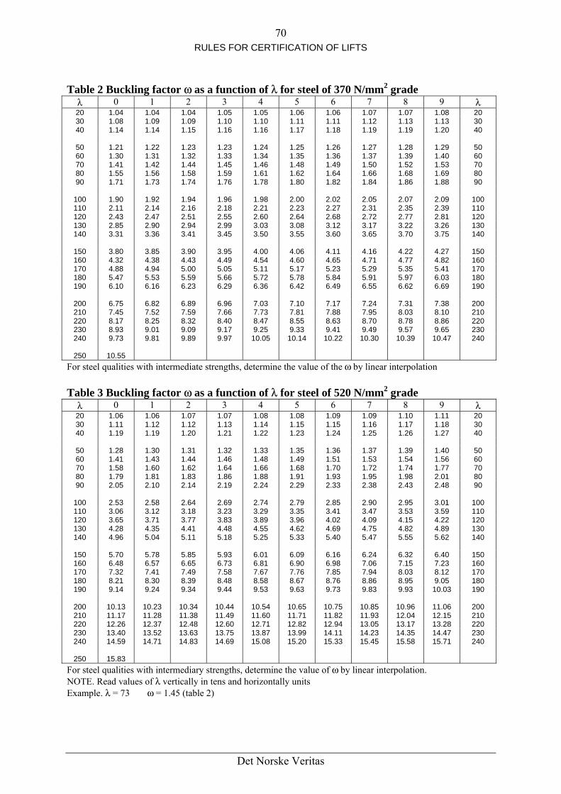
70 RULES FOR CERTIFICATION OF LIFTS
Table 2 Buckling factor ω as a function of λ for steel of 370 N/mm2 grade
λ 0 1 2 3 4 5 6 7 8 9 λ 20 1.04 1.04 1.04 1.05 1.05 1.06 1.06 1.07 1.07 1.08 20 30 1.08 1.09 1.09 1.10 1.10 1.11 1.11 1.12 1.13 1.13 30 40 1.14 1.14 1.15 1.16 1.16 1.17 1.18 1.19 1.19 1.20 40
50 1.21 1.22 1.23 1.23 1.24 1.25 1.26 1.27 1.28 1.29 50 60 1.30 1.31 1.32 1.33 1.34 1.35 1.36 1.37 1.39 1.40 60 70 1.41 1.42 1.44 1.45 1.46 1.48 1.49 1.50 1.52 1.53 70 80 1.55 1.56 1.58 1.59 1.61 1.62 1.64 1.66 1.68 1.69 80 90 1.71 1.73 1.74 1.76 1.78 1.80 1.82 1.84 1.86 1.88 90
100 1.90 1.92 1.94 1.96 1.98 2.00 2.02 2.05 2.07 2.09 100 110 2.11 2.14 2.16 2.18 2.21 2.23 2.27 2.31 2.35 2.39 110 120 2.43 2.47 2.51 2.55 2.60 2.64 2.68 2.72 2.77 2.81 120 130 2.85 2.90 2.94 2.99 3.03 3.08 3.12 3.17 3.22 3.26 130 140 3.31 3.36 3.41 3.45 3.50 3.55 3.60 3.65 3.70 3.75 140
150 3.80 3.85 3.90 3.95 4.00 4.06 4.11 4.16 4.22 4.27 150 160 4.32 4.38 4.43 4.49 4.54 4.60 4.65 4.71 4.77 4.82 160 170 4.88 4.94 5.00 5.05 5.11 5.17 5.23 5.29 5.35 5.41 170 180 5.47 5.53 5.59 5.66 5.72 5.78 5.84 5.91 5.97 6.03 180 190 6.10 6.16 6.23 6.29 6.36 6.42 6.49 6.55 6.62 6.69 190
200 6.75 6.82 6.89 6.96 7.03 7.10 7.17 7.24 7.31 7.38 200 210 7.45 7.52 7.59 7.66 7.73 7.81 7.88 7.95 8.03 8.10 210 220 8.17 8.25 8.32 8.40 8.47 8.55 8.63 8.70 8.78 8.86 220 230 8.93 9.01 9.09 9.17 9.25 9.33 9.41 9.49 9.57 9.65 230 240 9.73 9.81 9.89 9.97 10.05 10.14 10.22 10.30 10.39 10.47 240
250 10.55
For steel qualities with intermediate strengths, determine the value of the ω by linear interpolation Table 3 Buckling factor ω as a function of λ for steel of 520 N/mm2 grade
λ 0 1 2 3 4 5 6 7 8 9 λ 20 1.06 1.06 1.07 1.07 1.08 1.08 1.09 1.09 1.10 1.11 20 30 1.11 1.12 1.12 1.13 1.14 1.15 1.15 1.16 1.17 1.18 30 40 1.19 1.19 1.20 1.21 1.22 1.23 1.24 1.25 1.26 1.27 40
50 1.28 1.30 1.31 1.32 1.33 1.35 1.36 1.37 1.39 1.40 50 60 1.41 1.43 1.44 1.46 1.48 1.49 1.51 1.53 1.54 1.56 60 70 1.58 1.60 1.62 1.64 1.66 1.68 1.70 1.72 1.74 1.77 70 80 1.79 1.81 1.83 1.86 1.88 1.91 1.93 1.95 1.98 2.01 80 90 2.05 2.10 2.14 2.19 2.24 2.29 2.33 2.38 2.43 2.48 90
100 2.53 2.58 2.64 2.69 2.74 2.79 2.85 2.90 2.95 3.01 100 110 3.06 3.12 3.18 3.23 3.29 3.35 3.41 3.47 3.53 3.59 110 120 3.65 3.71 3.77 3.83 3.89 3.96 4.02 4.09 4.15 4.22 120 130 4.28 4.35 4.41 4.48 4.55 4.62 4.69 4.75 4.82 4.89 130 140 4.96 5.04 5.11 5.18 5.25 5.33 5.40 5.47 5.55 5.62 140
150 5.70 5.78 5.85 5.93 6.01 6.09 6.16 6.24 6.32 6.40 150 160 6.48 6.57 6.65 6.73 6.81 6.90 6.98 7.06 7.15 7.23 160 170 7.32 7.41 7.49 7.58 7.67 7.76 7.85 7.94 8.03 8.12 170 180 8.21 8.30 8.39 8.48 8.58 8.67 8.76 8.86 8.95 9.05 180 190 9.14 9.24 9.34 9.44 9.53 9.63 9.73 9.83 9.93 10.03 190
200 10.13 10.23 10.34 10.44 10.54 10.65 10.75 10.85 10.96 11.06 200 210 11.17 11.28 11.38 11.49 11.60 11.71 11.82 11.93 12.04 12.15 210 220 12.26 12.37 12.48 12.60 12.71 12.82 12.94 13.05 13.17 13.28 220 230 13.40 13.52 13.63 13.75 13.87 13.99 14.11 14.23 14.35 14.47 230 240 14.59 14.71 14.83 14.69 15.08 15.20 15.33 15.45 15.58 15.71 240
250 15.83
For steel qualities with intermediary strengths, determine the value of ω by linear interpolation. NOTE. Read values of λ vertically in tens and horizontally units Example. λ = 73 ω = 1.45 (table 2)
Det Norske Veritas
71 RULES FOR CERTIFICATION OF LIFTS
11. CLEARANCES BETWEEN CAR AND WALLS AND BETWEEN CAR AND COUNTERWEIGHT
11.1 General provision The clearances laid down in the Rules shall be maintained not only during the examinations and tests before the lift is put into service, but also throughout the life of the lift.
11.2 Clearance between car and wall 11.2.1 The horizontal distance between the inner surface of the lift well and the sill or framework of the car entrance or door (or entrance edge of doors in the case of sliding doors) shall not exceed 0.15 m. Specific cases The distance given above: a) may be extended to 0.2 m over a height not exceeding 0.5 m b) may be extended to 0.2 m throughout the travel on lifts mainly intended for transporting
loads, which are generally accompanied by people (including non-commercial vehicle lifts) in which the doors are vertically sliding
c) is not limited in the cases covered by 5.4.3.3. 11.2.2 The horizontal distance between the sill of the car and sill of the landing doors shall not exceed 35 mm. 11.2.3 The horizontal distance between the car door and the closed landing doors or the access distance between the doors during the whole of their normal operation shall not exceed 0.12 m.
11.3 Clearance between car and counterweight 11.3.1 The car and associated components shall have a distance of at least 0.05 m from the counterweight (if there is any) and associated components.
Det Norske Veritas
72 RULES FOR CERTIFICATION OF LIFTS
12 A. MACHINES FOR ELECTRIC LIFTS (For hydraulic lifts, see 12B) Contents 12.1 General provision 12.2 Drive of the car and the counterweight 12.3 Overhung pulleys or sprockets 12.4 Braking system 12.5 Emergency operation 12.6 Speed 12.7 Stopping the machine and checking its stopped condition 12.8 Checking the slowdown of the machine when reduced stroke buffers are used in
accordance with 10.4.3.2 12.9 Protection of machinery
12.1 General provision Each lift shall have at least one machine of its own.
12.2 Drive of the car and the counterweight 12.2.1 Two methods of drive are permissible: a) by traction (use of sheaves and ropes) b) by positive drive if the rated speed does not exceed 0.63 m/s, i.e.:
1) either use of a drum and ropes without counterweights, or 2) use of sprockets and chains. The calculations of the driving elements shall take into
account the possibility of the counterweight, if there is one, (or the car) resting on its buffers.
12.2.2 Use may be made of belts for coupling the motor or motors to the component on which the electro-mechanical brake (12.4.1.2) operates. A minimum of two belts shall be used.
12.3 Overhung pulleys or sprockets In the case of the use of overhung traction sheaves or sprockets, effective precautions shall be taken to avoid the following: a) The ropes leaving their grooves, or chains leaving their sprockets b) Objects lodging between the grooves and the ropes (or between sprockets and chains) in
the case where the machine is not above the well.
12.4 Braking system 12.4.1 General provisions 12.4.1.1 The lift shall be provided with a braking system which operates automatically: a) In the case of loss of the power supply b) In the event of the loss of the supply to the control circuits. 12.4.1.2 The braking system shall have an electro-mechanical brake (friction type), but may, in addition, have other braking means (e.g. electric).
Det Norske Veritas
73 RULES FOR CERTIFICATION OF LIFTS
12.4.2 Electro-mechanical brake 12.4.2.1 This brake on its own shall be capable of stopping the machine when the car is travelling at its rated speed and with the rated load plus 25°/o. In these conditions the retardation of the car shall not exceed that resulting from operation of the safety gear or stopping on the buffer. All the mechanical components of the brake which take part in the application of the braking action on the drum or disc must be installed in two sets and be of such dimensions that if one of the components were not working on the brake drum or disc, a sufficient braking effect to slow down the car when containing the allowable load would continue to be exercised. 12.4.2.2 The component on which the brake operates shall be coupled to the driving pulley (drum or sprocket) by direct mechanical means. 12.4.2.3 The brake shall be held off, normally, electrically. 12.4.2.3.1 The interruption of the current shall be controlled by at least two independent electric devices, whether linked or not with those which control the current to the machine. If, when the lift is stationary, one of the contactors has not opened the main contacts, further movements shall be prevented, at the latest at the next change in the direction of operation. 12.4.2.3.2 When the motor of the lift is likely to function as a generator, it shall not be possible for the electric device operating the brake to be fed by the driving motor. 12.4.2.3.3 Braking shall occur as soon as the electric circuit operating the brake is interrupted. (The use of a diode or a capacitor connected directly to the terminal of the brake coil is not considered as a means of delay). 12.4.2.4 Any machine fitted with a manual emergency operating device (12.5.1) shall be capable of having the brake released by hand and require a constant effort to keep the brake open. 12.4.2.5 The brake shoe pressure shall be exerted by guided compression springs or weights. 12.4.2.6 Braking shall be effected by application on the brake drum disc by at least two shoes, pads or callipers. 12.4.2.7 Band brakes are forbidden. 12.4.2.8 Brake linings shall be incombustible.
12.5 Emergency operation 12.5.1 If the manual effort required moving the car in the upward direction with its rated load does not exceed 400 N, the machine shall be provided with a manual means of emergency operation allowing the car to be moved to a landing with the aid of a smooth wheel. Arrangement with crank handle will not be permitted.
Det Norske Veritas

74 RULES FOR CERTIFICATION OF LIFTS
12.5.1.1 If the wheel is removable, it shall be located in an easily accessible place in the machine room. It shall be suitably marked if there is any risk of confusion as to the machine for which it is intended. 12.5.1.2 It shall be possible to check easily from the machine room whether the car is in an unlocking zone. This check may be made, for example, by means of marks on the suspension or governor ropes. 12.5.2 If the effort defined in 12.5.1 is greater than 400 N, a means of emergency electrical operation from the machine room shall be provided in accordance with 14.2.1.4.
12.6 Speed The speed of the lift measured in descent with half load and in the middle of travel, all acceleration and deceleration periods being excluded, the frequency of the supply being at its rated value and the voltage of the motor equal to the rated voltage of the equipment, shall not exceed the rated speed by more than 5% 1). _____ 1) It is good practice that in the above conditions the speed is not more than 8% less than the rated speed.
12.7 Stopping the machine and checking its stopped condition The stopping of the machine by means of an electric safety device, in conformity with 14.1.2, shall be controlled as detailed below. 12.7.1 Motors supplied directly from a.c. or d.c. mains The supply shall be interrupted by two independent contactors, the contactors of which shall be in series in the supply circuit. If, whilst the lift is stationary, one of the contactors has not opened the main contacts, further movement of the car shall be prevented at the latest at the next change in the direction of operation. 12.7.2 Drive using a 'Ward-Leonard' system 12.7.2.1 Excitation of the generator supplied by classical elements. Two independent contacts shall interrupt, either: a) the motor generator loop, or b) the excitation of the generator, or c) one the loop and the other the excitation of the generator. If, whilst the lift is stationary, one of the contactors has not opened the main contacts, further movement of the car shall be prevented, at the latest at the next change in direction of operation. In cases (b) and (c) effective precautions shall be taken to prevent the rotation of the motor in the case of a residual field, if any, in the generator (.e.g. suicide circuit). 12.7.2.2 Excitation of the generator supplied and controlled by static elements. One of the following methods shall be used: a) same method as laid down in 12.7.2.1 b) a system consisting of:
1) a contactor interrupting the excitation of the generator or the generator motor loop. The coil of the contactor shall be released at least before each change in direction of
Det Norske Veritas

75 RULES FOR CERTIFICATION OF LIFTS
operation. If the contactor does not release, any further movement of the lift shall be prevented.
2) a control device blocking the flow of energy in the static elements 3) a monitoring device to verify the blocking of the flow of energy each time the lift is
stationary. If, during a normal stopping period, the blocking by the static elements is not effective, the monitoring device shall cause the contactor to release and any further movement of the lift shall be prevented. Effective precautions shall be taken to prevent the rotation of the motor in the case of a residual field, if any, in the generator (e.g. suicide circuit).
12.7.3 A.c. or d.c. motor supplied and controlled by static elements One of the following methods shall be used: a) Two independent contactors interrupting the current to the motor. If, while the lift is
stationary, one of the contactors has not opened the main contacts, any further movement shall be prevented, at the latest at the next change in direction of operation.
b) A system consisting of: 1) A contactor interrupting the current at all poles.
The coil of the contactor shall be released at least before each change in direction. If the contactor does not release, any further movement of the lift shall be prevented.
2) A control device blocking the flow of energy in the static elements. 3) A monitoring device to verify the blocking of the flow of energy each time the lift is
stationary. If, during a normal stopping period, the blocking by the static element is not effective, the monitoring device shall cause the contactor to release and any further movement of the lift shall be prevented.
12.8 Checking the slowdown of the machine when reduced stroke buffers are used in accordance with 10.4.3.2
12.8.1 Devices shall check that the slowdown is effective before arrival at terminal landing. 12.8.2 If the slowdown is not effective these devices shall cause the car speed to be reduced in such a way that, if the car comes into contact with the buffers, the striking speed shall not exceed that for which the buffers were designed. 12.8.3 If the device checking the slowdown is not independent of the direction of travel, a device shall check that the movement of the car is in the intended direction. 12.8.4 If these devices, or some of them, are placed in the machine room: a) they shall be operated by a device directly coupled to the car b) the information relating to the car position shall not depend on devices driven by traction,
friction, or by synchro-motors c) if a connection by tape, chain or rope is used to transmit the position of the car to the
machine room, breakage of or slack in the device shall cause the machine to stop through the action of an electric device in conformity with 14.1.2.
Det Norske Veritas
76 RULES FOR CERTIFICATION OF LIFTS
12.8.5 The control and functioning of these devices shall be so designed that together with the normal speed regulation system there results a slowdown control system complying with the requirements of 14.1.2.
12.9 Protection of machinery Effective protection shall be provided for accessible rotating parts which may be dangerous, in particular: a) keys and screws in the shafts b) tapes, chains, belts c) gears, sprockets d) projecting motor shafts e) fly-ball type overspeed governors Exceptions are made for traction sheaves, hand-winding wheels, brake drums and any similar smooth, round parts. Such items shall be painted yellow, at least in part.
Det Norske Veritas

77 RULES FOR CERTIFICATION OF LIFTS
12 B. MACHINE, JACK AND OTHER HYDRAULIC EQUIPMENT
(For electric lifts, see 12A) Contents 12.10 General provisions 12.11 Jack 12.12 Piping 12.13 Stopping the machine and checking its stopped condition 12.14 Hydraulic control and safety devices 12.15 Checking the pressure 12.16 Checking the hydraulic fluid level in the tank 12.17 Speed 12.18 Emergency operation 12.19 Protection of the pulley on the jack 12.20 Protection of machinery 12.21 Precautions against over-heating of the hydraulic fluid Clause 12B Notes
12.10 General provisions 12.10.1 Each lift shall have at least one machine of its own. The two following methods of drive are permissible: a) direct acting b) indirect acting
see clause 2 «Definitions». 12.10.3 If several jacks are used to raise the car they shall be hydraulically connected to ensure pressure equilibrium. 12.10.3 The mass of the counterweight, if any, shall be calculated such that in case of a rupture of the suspension gear (car-counterweight), the pressure in the hydraulic system does not exceed 2 times full load pressure. In the case of several counterweights, the rupture of only one suspension gear shall be taken into consideration for the calculation.
12.11 Jack 12.11.1 Calculations of cylinder and ram 12.11.1.1 The cylinder and the ram shall be designed to withstand a pressure equal to 2.3 times the full load pressure. A safety factor of 1.7 referred to the proof stress (non proportional elongation) of the material shall be taken into account. In the thickness calculations an additional value of 1.0 mm for cylinder walls and cylinder bases and of 0.5 mm for ram shall be taken into account.
Det Norske Veritas

78 RULES FOR CERTIFICATION OF LIFTS
The calculations shall be carried out according to the notes to clause 12, sub clause 1.1 and 1.2 nevertheless the examples shown do not prejudge other possible constructions. 12.11.1.2 Jacks under compressive stress shall fulfil the following requirements: 12.11.1.2.1 They shall be designed to withstand in their fully extended position the forces acting when the pressure is equal to 1.4 times full load pressure. A safety factor of 2.5 against buckling shall be used. The calculations shall be carried out according to the notes to clause 12 sub clause 2. 12.11.1.2.2 For single jack calculations the guiding of the ram in the cylinder and the fixing of the cylinder shall be taken into consideration. The ram fully extended, up to the compression of the cushioned stop, the effective buckling length lk to be taken into account is equal to: a) In the case of jacks without internal guiding (length of bearing < 2 times the diameter of
the ram) or in the case of flexibly fixed cylinders: The distance between the centre of the ram guide in the cylinder (or the articulation centre line of the cylinder fixing) and either the articulation centre line of the ram connection to the car, or the centre line of the ram head pulley (Euler case 2).
b) In the case of jacks with rigidly fixed cylinder and sufficient internal guidance; 0.7 times the distance between the ram guide in the cylinder and either the articulation centre line of the ram connection to the car, or the centre line of the ram head pulley (Euler case 3).
12.11.1.2.3 For telescopic jacks calculations shall take into consideration the system used for guiding the sections. The sections being fully extended, up to the compression of the cushioned stops, the effective buckling length l to be taken into account is equal to: a) In the case of external guidance:
The distance between the centre of the guide of the smallest ram and the articulation centre line of the connection of this ram to the car (Euler case 2). The calculation of the other sections shall be made by analogy.
b) In the case of external guidance, biggest cylinder articulated: The distance between the articulation centre line of the biggest cylinder and the articulation centre line of the jack connection to the car (Euler case 2).
c) In the case of internal guidance, biggest cylinder fixed: 0.7 times the distance between the ram guide in the fixed cylinder and the articulation centre line of the jack connection to the car (Euler case 3).
12.11.1.3 Jacks under traction stress shall fulfil the following requirements: They shall be designed to withstand the forces acting when the pressure is equal to 1.4 times full load pressure. A safety factor of 2.5 referred to the proof stress of the material shall be used. 12.11.2 Connection Car/ram (Cylinder) 12.11.2.1 In case of a direct acting lift the connection between the car and the ram (cylinder) shall be flexible.
Det Norske Veritas

79 RULES FOR CERTIFICATION OF LIFTS
12.11.2.2 The connection between the car and the ram (cylinder) shall be so constructed to support the weight of the ram (cylinder) and the additional dynamic forces. The connection means shall be secured. 12.11.2.3 In case of a ram made with more than one section, the connections between the sections shall be so constructed to support the weight of the suspended elements and the additional dynamic forces. 12.11.2.4 In the case of indirect acting lifts, the ram (cylinder) head shall be guided. This requirement does not apply for pulling jacks provided the pulling arrangement assures the guiding of the ram head under all conditions. 12.11.2.5 In the case of indirect acting lifts, no parts of the ram head guiding system shall be incorporated within the vertical projection of the car roof. 12.11.3 Limitation of the ram stroke 12.11.3.1 Means shall be provided to stop the ram with buffered effect in such a position that the requirements of 5.7.1.1 may be satisfied. 12.11.3.2 This limit shall either: a) be a cushioned stop, or b) be effected by shutting off the hydraulic supply to the jack by means of a mechanical
linkage between jack and a hydraulic valve; breakage or stretch of such a linkage shall not result in the failure of the car to achieve the deceleration required by 12.11.3.3.2.
12.11.3.3 Cushioned stop 12.11.3.3.1 This stop shall either: a) be an integral part of the jack, or b) consist of one or more device external to the jack situated outside the car projection, the
resultant force of which is exerted on the centre line of the jack. 12.11.3.3.2 The design of the cushioned stop shall be such that the average deceleration of the car does not exceed 1.0 g and that in the case of an indirect acting lift the deceleration does not result in slack rope or chain. 12.11.3.4 In cases 12.11.3.3.1 (b) and 12.11.3.2 (b) a stop shall be provided inside the jack to prevent the ram from leaving the cylinder. 12.11.4 Means of protection 12.11.4.1 If a jack extends into the ground, it shall be installed in a protective tube. If it extends into other spaces it shall be suitably protected. 12.11.4.2 Leak and scrape fluid from the cylinder shall be collected. 12.11.4.3 The jack shall be provided with a manual air venting device. 12.11.5 Telescopic jack
Det Norske Veritas

80 RULES FOR CERTIFICATION OF LIFTS
The following requirements apply additionally. 12.11.5.1 Stops shall be provided between successive sections to prevent the rams from leaving their respective cylinders. 12.11.5.2 In the case of jack below the car of a direct acting lift, the clear distance between the successive guiding yokes and between the highest guiding yoke and the lowest parts of the car (parts mentioned in 5.7.2.2, b 2) excluded, shall be at least 0.3 m when the car rests on its fully compressed buffers. 12.11.5.3 The length of the bearing of each section of a telescopic jack with internal guidance, shall be at least 2 times the diameter of the respective ram. 12.11.5.4 These jacks shall be provided with mechanical or hydraulic synchronising means. 12.11.5.5 If they have multiple fluid compartments, the calculation of the whole hydraulic system shall be based on the static pressure of the compartment with the highest pressure. a) there shall be at least two independent ropes or chains b) the requirements of 9.4 apply c) the safety factor shall be at least:
12 for ropes 10 for chains The safety factor is the ratio between the minimum breaking load (N) of one rope (one chain) and the maximum force in this rope (in this chain), when the car is stopped with rated load.
d) A device shall be provided which prevents the speed of the car exceeding the rated speed downwards (vd ) + 0.3 m/s in the event of failure of the synchronizing means.
12.12 Piping 12.12.1 General 12.12.1.1 Piping and fittings which are subject to pressure (connections, valves etc) as in general all components of a lift hydraulic system shall: a) be appropriate to the fluid used b) be designed and installed in such a way to avoid any abnormal stress due to fixing, torsion
or vibration c) be protected against damage, in particular of mechanical origin. 12.12.1.2 Pipes and fittings shall be appropriately fixed and accessible for inspection. If pipes (either rigid or flexible) pass through walls or floor they shall be protected by means of ferrules, the dimensions of which allow the dismantling, if necessary, of the pipes for inspection. No coupling must be sited inside a ferrule. 12.12.2 Rigid pipes 12.12.2.1 Rigid pipes and fittings between cylinders, non return valve or down direction valve(s) shall be designed to withstand a pressure equal to 2.3 times the full load pressure. A safety factor of 1.7 referred to the proof stress of the material shall be taken into account. In the thickness calculation an additional value of 1.0 mm for the circuit between the cylinder
Det Norske Veritas

81 RULES FOR CERTIFICATION OF LIFTS
and the rupture valve, if any, and of 0.5 mm for the other rigid pipes, shall be taken into account. The calculations shall be carried out according to the notes to clause 12, sub clause 1.1. 12.12.2.2 For the evaluation of the full load pressure in the case of a telescopic jack with several fluid compartments, the requirements of 12.11.5.5 shall be taken into account. 12.12.3 Flexible hoses 12.12.3.1 The flexible hose between cylinder and non return valve or down direction valve, shall be selected with a safety factor of at least 8 between full load pressure and bursting pressure. 12.12.3.2 The flexible hose and its couplings between cylinder and non return valve or down direction valve shall: a) withstand without damage a pressure of 5 times full load pressure, this test to be carried
out by the manufacturer of the hose. b) be marked in an indelible manner with the name of the manufacturer or trade mark, the
test pressure, the date of the test c) not be fixed with a bending radius smaller than that indicated by the hose manufacturer.
12.13 Stopping the machine and checking its stopped condition A stop of the machine due to the operation of an electrical safety device in conformity with 14.1.2 shall be controlled as detailed below: 13.13.1 For upwards motion either: a) the supply to the electric motor shall be interrupted by at least two independent
contactors, the main contacts of which shall be in series in the motor supply circuit, or b) the supply to the electric motor shall be interrupted by one contactor, and the supply to
the by-pass valve shall be interrupted by at least two independent electrical devices connected in series in the supply circuit of these valves.
12.13.2 For downwards motion The supply to the down valve(s) shall be interrupted, either: a) by at least two independent electrical devices connected in series, or b) directly by the electrical safety device provided it is suitably rated electrically. 12.13.3 In any of the above cases 12.13.1 or 12.13.2 where two independent contactors or electrical devices are in series, if whilst the lift is stationary, one of these contactors has not opened, the main contacts or one of these electrical devices has not opened, a further start shall be prevented, at the latest at the next change in the direction of motion.
12.14 Hydraulic control and safety devices 12.14.1 Shut off valve 12.14.1.1 A shut off valve shall be provided. It shall be installed in the circuit from the cylinder to the non return valve and the down direction valve(s). 12.14.1.2 It shall be located in the machine room.
Det Norske Veritas

82 RULES FOR CERTIFICATION OF LIFTS
12.14.2 Non return valve 12.14.2.1 A non return valve shall be provided. It shall be installed in the circuit between the pump(s) and the shut off valve. 12.14.2.2 The non return valve shall be able to hold the lift car with the rated load at any point when the supply pressure drops below the minimum operating pressure. 12.14.2.3 The closing of the non return valve shall be effected by the hydraulic pressure from the jack and by at least one guided compression spring and/or by gravity. 12.14.3 Pressure relief valve 12.14.3.1 A pressure relief valve shall be provided. It shall be connected to the circuit between the pump(s) and the non return valve. The hydraulic fluid shall be returned to the tank. 12.14.3.2 The pressure relief valve shall be adjusted to limit the pressure to 140% of the full load pressure. 12.14.3.3 When needed due to high internal losses (head loss, friction), the pressure relief valve may be set to a greater value but not exceeding 170% of full load pressure. In this case, for the calculations of the hydraulic equipment (including jack) a fictious full load pressure equal to:
4.1a) (Mp setting pressure Selected
shall be used. In the calculation against buckling the overpressure factor of 1.4 shall be replaced by a factor corresponding to the increased setting of the pressure relief valve. 12.14.4 Direction valves 12.14.4.1 Down direction valves Down direction valves shall be held open electrically. The closing shall be effected by the hydraulic pressure from the jack and/or by at least one guided compression spring. 12.14.4.2 Up direction valves If the stopping of the machine is effected in accordance with 12.13.1 b), only by-pass valves shall be used for this. Each shall be closed electrically. Its opening shall be effected by the hydraulic pressure from the jack and/or by at least one guided compression spring. 12.14.5 Rupture valve (See 9.16 for cases of application)
Det Norske Veritas

83 RULES FOR CERTIFICATION OF LIFTS
12.14.5.1 The rupture valve shall be capable of stopping the down moving car and maintaining it stationary, at the latest when the speed reaches a value equal to the rated speed plus 0.3 m/s. The average deceleration shall not exceed 1.0 gn. 12.14.5.2 The rupture valve shall be accessible for adjustment and inspection. 12.14.5.3 On lifts with several jacks, operating in parallel, one common rupture valve may be used. Otherwise the rupture valves shall be interconnected to cause simultaneous closing. In order to avoid the floor of the car from inclining by more than 5% from its normal position. 12.14.6 Restrictor (or one way restrictor) (See 9.16 for cases of application). In the case of a major leakage in the hydraulic system, the restrictor shall limit the speed of the car with rated load to a maximum of rated speed downwards plus 0.3 m/s. 12.14.7 Filters In the circuit between the tank and the pump(s) and in the circuit to the down direction valve(s), filters or similar devices shall be installed. The down direction valves filter or similar device(s) shall be accessible for inspection and maintenance.
12.15 Checking the pressure 12.15.1 To the circuit between the non return valve or the down direction valve(s) and the shut off valve, there shall be connected either: a) a pressure gauge connection which shall normally be terminated with a threaded tap plug,
or b) a pressure gauge which can be shut off. 12.15.2 If the lift is not fitted with a permanently installed hand operated hydraulic device which permits movement of the car upwards, a connection for a hand pump shall be connected to the circuit between the non return valve or the down direction valve(s) and the shut off valve. The connection shall normally be terminated with a threaded tap plug. This connection is not required if a connection for a pressure gauge is provided. 12.15.3 The connection for the pressure gauge and/or the hand pump shall be provided with an internal thread of either M 20 × 1.5 or G 1/2.
12.16 Checking the hydraulic fluid level in the tank It shall be easy to check that the hydraulic fluid is on the correct level.
12.17 Speed 12.17.1 The rated speed (v ) shall not be greater than 1.0 m/s, unless additional requirements are fulfilled. 12.17.2 The speed of the empty car upwards shall not exceed the rated upward speed by more than 8 %, and the speed of the car with rated load downward shall not exceed the rated downward speed by more than 8 %, in each case at the normal operating temperature of the hydraulic fluid. For a travel in up direction it is supposed that the frequency of the supply is at
Det Norske Veritas

84 RULES FOR CERTIFICATION OF LIFTS
its rated value and that the voltage on the motor terminals is equal to the rated voltage of the electric equipment.
12.18 Emergency operation 12.18.1 Moving the car downwards 12.18.1.1 The lift shall be provided with a manually operated valve located in the machine room allowing even in the case of a power failure the car to be lowered to a level where the passengers can leave the car. 12.18.1.2 The speed of the car shall not exceed 0.3 m/s. 12.18.1.3 The functioning of this valve shall require a constant effort. 12.18.1.4 This valve shall be protected against involuntary action. 12.18.1.5 In the case of indirect acting lifts where slack rope or slack chain can occur, the operation of this valve shall not be effective when the pressure is below the minimum operating pressure. 12.18.2 Moving the car upwards 12.18.2.1 A manually operated hydraulic device which permits to move the car in upward direction shall be permanently installed. 12.18.2.2 This device shall be connected to the circuit between the non return valve or down direction valve(s) and the shut off valve. 12.18.2.3 This device shall be equipped with a pressure relief valve limiting the pressure to 2.3 times of the full load pressure. 12.18.3 Checking of the car position If the lift serves more than two levels, it shall be possible to check from the machine room whether the car is in an unlocking zone by a means which is independent of the power supply.
12.19 Protection of the pulley on the jack Necessary provisions shall be made to avoid: a) bodily injury b) the suspension ropes (or chains), if slack, leaving their grooves (or pulleys) c) the introduction of objects between ropes (or chains) and grooves (or pulleys) The devices
used shall be so constructed that they do not hinder inspection or maintenance of the pulley.
12.20 Protection of machinery Effective protection shall be provided for accessible rotating parts which may be dangerous, in particular: a) keys and screw in the shafts b) tapes, chains, belts c) gears, sprockets
Det Norske Veritas

85 RULES FOR CERTIFICATION OF LIFTS
d) projecting motor shafts e) fly-ball type overspeed governors
12.21 Precautions against over-heating of the hydraulic fluid It shall be provided either: a motor run time limiter (12.21.1) or: an electric temperature detecting device (12.21.2). 12.21.1 Motor run time limiter 12.21.1.1 This device shall stop the machine and keep it stopped when the motor remains energized longer than the time required for the full travel, upwards with rated load, plus a maximum of 60 s. 12.21.1.2 The return to service shall only be possible by manual resetting. However, on restoration of the power supply after it has been interrupted, it is not required to keep the machine stopped. 12.21.1.3 This device shall not affect the inspection operation. 12.21.2 Electric temperature detecting device 12.21.2.1 This device shall stop the machine and keep it stopped when the temperature of the hydraulic fluid in the tank exceeds a preset value. 12.21.2.2 The return to service shall only be possible by manual resetting. However, on restoration of the power supply after it has been interrupted, it is not required to keep the machine stopped.
Det Norske Veritas

86 RULES FOR CERTIFICATION OF LIFTS
Clause 12B. Notes
1. Calculation against overpressure
1.1 Calculation of wall thicknesses of rams, cylinders, rigid pipes and fittings
e0 = 1.0 mm for wal1 end base of cylinders and rigid pipes between the cylinder and the
rupture valve, if any. = 0.5 mm for rams and other rigid pipes.
1.2 Calculation of the base thickness of cylinders (examples) 1.2.1 Flat bases with relieving groove
2.3 = actor for friction losses (1.15) and pressure peaks (2). ty factor referred to the proof stress. 1.7 = safe
Det Norske Veritas
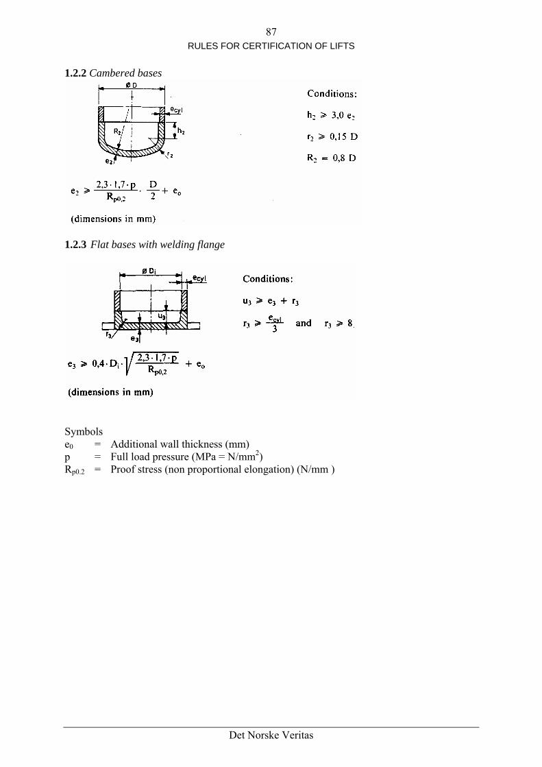
87 RULES FOR CERTIFICATION OF LIFTS
1.2.2 Cambered bases
1.2.3 F tla bases with welding flange
Symbols e0 = Additional wall thickness (mm) p = Full load pressure (MPa = N/mm2) Rp0.2 = Proof stress (non proportional elongation) (N/mm )
Det Norske Veritas

88 RULES FOR CERTIFICATION OF LIFTS
2. Calculation of the rams against buckling
2.1 Jacks with rigidly fixed cylinder without internal guidance (as shown) or jacks with flexibly fixed cylinder
Euler case 2
or λ ≥ 110: F n
'Jl5.2
F yyn2k
5 ⋅⋅
≤ E2 ⋅π
or λn < 110: F
⎥⎥⎦
⎤
⎢⎢⎣
⎡⎟⎠⎞
⎜⎝⎛ λ⋅−−≤
2n
mmn
5 100)210R(R
5.2A F
* [ ]'rrhrmn5 cg4.1F ⋅= PPP64.0)QP( ++++ * (valid for rams extending in up direction)
Det Norske Veritas

89 RULES FOR CERTIFICATION OF LIFTS
2.2 Jacks with rigidly fixed cylinder without internal guidance
Single jacks Euler case 3
For λ ≥ 110: n
'Jl5.2EF yyn2k
2
5 ⋅⋅⋅π≤
For λn < 110:
⎥⎥⎦
⎤
⎢⎢⎣
⎡⎟⎠⎞
⎜⎝⎛ λ⋅−−≤
2n
mmn
5 100)210R(R
5.2AF
* [ ]'rrhrmn5 PPP64.0)QP(cg4.1F ++++⋅= * (valid for rams extending in up direction)
Det Norske Veritas

90 RULES FOR CERTIFICATION OF LIFTS
21
ll1 =
31
ll1 =
)'J'J'J()'J'J('J 1yy2yy
2yy>=
'J 1yyv'J
v 1yy2yy3yy2yy
>≥=
ϕ = 1.25 v – 0.25 (assumption for simplified calculation: J
'J 1yy
yy3’ = Jyy2’ ϕ = 1.25 v – 0.2 for 0.22 < v < 0.65 ϕ = 0.65 v + 0.35
for 0.65 ≤ v ≤ 1 λt = lk/i
⎥⎥⎦⎢
⎢⎣
⎟⎟⎠
⎜⎜⎝
+ϕ=m
mmd
14
i ⎤⎞'d⎡ ⎛
2d
Det Norske Veritas

91 RULES FOR CERTIFICATION OF LIFTS
For λt ≥ 110:
ϕ⋅⋅⋅⋅π≤ 'Jl5.2EF 2yy2k
5
For λ
2
he section with the smallest metallic cross section t < 110:
alculation of tC
⎥⎥⎤
⎢⎡
⎟⎞
⎜⎛ λ⋅−−≤
2n
mmn
5 )210R(RAF ⎦⎣
* ⎢ ⎠⎝1005.2
[ ]'rrhrmn5 PPP64.0)QP(cg4.1F ++++⋅= * (valid for rams extending in up direction)
tio
’ = Inner diameter of the biggest ram (mm)
ration of free fall (m/s2) to be analysed (mm) (n = 1, 2, 3)
’ = Effective geometric moment of inertia of stage/section to be analysed (mm2) (n = 1,
les
= Mass of the ram to be analysed the ram under analysis (in the case of telescopic jacks)
(kg)
kg) = Tensile strength of materials (N/mm2)
Symbols: An = Metallic cross sectional area of the stage/section to be analysed (mm2) (n 0 1, 2,3) cm = Reeving radm = Outside diameter of the biggest ram (mm) dmE = Modulus of elasticity (N/mm2)(for steel. E = 2.1 105 N/mm2) F5 = Effective buckling force (N) gn = Standard accelei = Radius of gyration of the stage/sectionni = Radius of gyration (mm) Jyy
2, 3) lk = Buckling length (mm) P = Sum of the mass of the empty car and the mass of the portion of the travelling cab
suspended from the car (kg) PrPr’ = Mass of the ram(s) acting on
Prh = Mass of the ram head equipment, if any (kg) Q = Rated load (mass) (Rm
λn = lk/in = Coefficient of slenderness of the section under analysis λt = lk/i = Equivalent coefficient of slenderness 1.4 = Over pressure factor 2.5 = Safety factor against buckling
Det Norske Veritas

92 RULES FOR CERTIFICATION OF LIFTS
13. ELECTRIC INSTALLATIONS AND APPLIANCES Contents
3.1 General provisions 113.2 Contactors, relay-contactors, components of safety circuits 1 13.3 Protection of motors 13.4 Main switches 13.5 Electric wiring 13.5 Lighting and socket-outlets
dard relating to the installation and to the constituent ly:
and dependent circuits cuit and dependent circuits
e considered as a whole, in the same way as a machine with its incorporated
Tin 13.1.1existing − on th− on th Whenev
ithin w used.
which, nationally, will also be acceptable.
providin 13.1.3 The resistance of the insulation between conductors and between conductors and earth shall be greater than 1 000 Ohm/V with a minimum of: a) 500 000 Ohm for power circuits and electric safety device circuits
13.1 General provisions 13.1.1 Limits of application
stan13.1.1.1 The requirements of thiscomponents of the electrical equipment app
cuita) to the main switch of the power cirb) to the switch for the car lighting cir
h lift should be Tapparatus. 13.1.1.2 National regulations relating to electric supply circuits shall apply as far as the inputterminals of the switches referred to in 13.1.1.1. They shall apply to the whole of the lighting ircuit in the machine room, the pulley room and the well and pit. c
13.1.13 he requirements of this standard for circuits’ dependent on the switches referred to
.1 are based, as far as possible, taking into account the specific needs of lifts, on standards: e international level : IEC e European level : CENELEC
er one of these standards is used, its references are given, together with the limits hich it isw
When no precise information is given, the electrical equipment used shall conform to the accepted Codes of Practice relating to safety, e.g. Det Norske Veritas' Rules for Steel Ships and Mobile Offshore Units Part 4, Chapter 4, Electrical Installations. 13.1.1.4 Countries which have not explicitly stated that they are in favour of one of the IEC of CENELEC standards may, whenever the standard involved is quoted, define components of quivalent quality e
13.1.2 In the machine and pulley rooms, protection against direct contact by means of casings
g a degree of protection of at least IP 2X is necessary.
Det Norske Veritas

93 RULES FOR CERTIFICATION OF LIFTS
b) 250 000 Ohm for other circuits (controls, lighting, signalling, etc).
s, relay-contactors, components of safety circuits ntactors
levant utilization category according to clause 4.3.6 and table I of IEC
ublication 158-1.
3.2.1.2 If, because of the current they carry, relay contactors must be used to operate the ed in
) DC-11 for controlling d.c. electromagnets
in 13.2.1.2 it may be assumed in the measures taken to comply with 14.1.1.1 that: ) if one of the break contacts (normally closed) is closed, all the make contacts are open
13.2.2.1 of 13.2.1
3.2.2.2 If relays are used which are such that the break and make contacts are never closed e
3.2.2.3 Devices (if any) connected after electrical safety devices shall meet the requirements rds the creep distances and the air gaps (not the separation distances).
13.3 Protection of motors shall be protected against short-circuiting.
o the motor in all live conductors.
13.1.4 The mean value in direct current or the r.m.s. value in alternating current of the voltage between conductors or between conductors and earth, shall not exceed 250 V for control and afety circuits. s
13.1.5 The neutral conductor and the earth-continuity conductor shall always be separate.
3.2 Contactor113.2.1 Contactors and relay co 13.2.1.1 The main contactors (i.e. those necessary to stop the machine as per 12.7 and 12.13)shall belong to the rePThese contactors shall in addition meet the Class 3 requirements of clause 4.3.4.3.1. 1main contactors, those relay contactors shall belong to the following categories as definIEC Publication 337-1: a) AC-11 for controlling a.c. electromagnets b 13.2.1.3 Both for the main contactors referred to in 13.2.1.1 and for the relay contactors referred toab) if one of the make contacts (normally open) is closed, all the break contacts are open. 13.2.2 Components of safety circuits
When devices as per 13.2.1.2 are used, as relays in a safety circuit, the assumptions .3 shall also apply.
1simultaneously for any position of the armature, the possibility of partial attraction of tharmature (14.1.1.1 (f) can be disregarded). 1of 14.1.2.2.2 as regaThis requirement does not apply to the devices mentioned in 13.2.1.1, 13.2.1.2 and 13.2.2.1 and which are required to meet the requirements of IEC Publication 158-1 and 337-1.
13.3.1 Motors directly connected to the mains 13.3.2 Motors directly connected to the mains shall be protected against overloads by means of manual reset (except as provided for in 13.3.3) automatic circuit-breakers which shall cut off the supply t
Det Norske Veritas

94 RULES FOR CERTIFICATION OF LIFTS
13.3.3 When the detection of overloads operates on the basis of temperature increases in the windings of the motor, the circuit-breaker may be closed automatically after sufficient cooling
ings upplied by different circuits.
13.3.5 W g motor sh
3.4 Main switches eaking the
upply to the lift on all the live conductors. This switch shall be capable of interrupting the
) socket outlet on the car roof
) lighting of the lift well
3.4.2 The main switches as defined in 13.4.1 shall have stable open and closed positions. The control mechanism for the main switch shall be easily and rapidly accessible from the entrance(s) to the machine room. If the machine room is common to several lifts, the control mechanism of the main switches shall allow the lift concerned to be identified easily. NOTE If the machine room has several points of access, or if the same lift has several
machine rooms each with its own point(s) of access, a circuit breaker contactor may be used, release of which shall be controlled by an electric safety device, in conformity with 14.1.2, inserted in the supply circuit to the coil of the circuit breaker contactor. The re-engagement of the circuit breaker contactor shall not be carried out or made possible except by means of the device which caused its release. The circuit breaker contactor shall be used in conjunction with a manually controlled isolating switch.
13.4.3 In the case of a group of lifts, if, after the opening of the main switch for one lift, parts of the operating circuits remain live, these circuits shall be capable of being separately isolated in the machine room, if necessary, by breaking the supply to all the lifts in the group. 13.4.4 Any capacitors to correct the power factor shall be connected before the main switch of the power circuit. NOTE If induced voltages are possible, for example when the motors are connected by very
long cables, the switch of the power circuit shall also interrupt the connection to the capacitors.
down has taken place. 13.3.4 The provisions of 13.3.2 and 13.3.3 apply to each winding if the motor has winds
hen the lifting motors are supplied by d.c. generators driven by motors, the liftinall also be protected against overload.
113.4.1 Machine rooms shall contain, for each lift, a main switch capable of brshighest current involved in normal conditions of use of the lift. This switch shall not cut the circuits feeding: a) car lighting or ventilation, if any bc) lighting of machine and pulley rooms d) socket outlet in the machine room ef) alarm device 1
Det Norske Veritas
95 RULES FOR CERTIFICATION OF LIFTS
13.5 Electric wiring 13.5.1 In the machine and pulley rooms and lift wells, the condu
tion of travelling cables) shall comply with the relevant speC Publ. 92 series.
ctors and cables (with the excep cifications for ship cables in
e IE
ors are at least to comply with the specifications of
inals and connectors, except those defined in 13.1.2, , boxes or on panels provided for this purpose.
ain switch or switches of a lift, some connection inals which are not live, and if
.5tes
ntinuity of mechanical protection, the protective sheathing of es shall fully enter the casings of switches and appliances, or shall
nical damage due to movement of parts or sharp
circuits have different cified for the highest
plug-in type placed in safety circuits, shall be so designed and does not require the use of a tool, it is impossible to insert
ion th
th
3.5.2 Cross-sectional area of conductors.1Cables for electric safety, circuits of doIEC Publ. 92-376. 13.5.3 Method of installation 13.5.3.1 The electric installation shall be provided with the indications necessary to make it easy to understand. 13.5.3.2 Connections, connection termshall be located in cabinets 13.5.3.3 If, after the opening of the mterminals remain live, they shall be clearly separated from termthe voltage exceeds 50 V, they shall be suitably marked.
.3.4 Connection 13 terminals whose accidental interconnection could lead to dangerous d of construction obviamalfunction of the lift, shall be clearly separated unless their metho
this risk. 13.5.3.5 In order to ensure coconductors and cablterminate in a suitably constructed gland. NOTE Enclosed frames of landing and car doors are regarded as appliance casings.
However, if there is a risk of mechaedges of the frame itself, the conductors connected to the electric safety device shall be protected mechanically.
13.5.3.6 If the same ducting or cable contains conductors whose voltages, all the conductors or cables shall have the insulation spevoltage. 13.5.4 Connectors Connectors and devices of the arranged that, if their withdrawalthe plug incorrectly.
13.6 Lighting and socket outlets 13.6.1 The electric lighting supplies to the car, the well and the machine rooms, shall be independent of the supply to the machine, either through another circuit or through connectto e machine supply circuit on the supply side of the main switch or the main switches laid down in 13.4.
Det Norske Veritas

96 RULES FOR CERTIFICATION OF LIFTS
13.6 n the machine and pulley rooms nd in the pit, shall be taken from the circuits referred to in 13.6.1.
r supplied by safety extra low voltage according to IEC Publ. 364-4-41.
above socket outlets does not imply that the supply cable has a cross-sectional area corresponding to the rated current of the socket outlet. The cross-
3.6.3 Isolation of lighting circuits and supply circuits for the socket outlets
achine room ontains several lift machines, it is necessary to have one switch per car). This switch shall be
ll control the supply to the circuit of the machine room, well and pit. his switch shall be located inside and close to the access to the machine room.
e
.2 The supply to socket outlets required on the car roof, iaThese socket outlets are: − either of type 2 P+T, 250 V, supplied directly, o− NOTE The use of the
sectional area of the conductors may be smaller, provided that the conductors are correctly protected against excess currents.
1 13.6.3.1 A switch shall control the supply to the circuit of the car. (If the mclocated close to the corresponding main power switch. 13.6.3.2 A switch shaT 13.6.3.3 Each circuit controlled by the switches laid down in 13.6.3.1 and 13.6.3.2 shall havits own protection.
Det Norske Veritas

97 RULES FOR CERTIFICATION OF LIFTS
14. PROTECTION AGAINST ELECTRIC FAULTS - CONTROLS - PRIORITIES
ontents and priorities C
14.1 Protection against electric faults
4.2 Controls and priorities
s ny one of the faults envisaged in 14.1.1.1 in the electric equipment of the lift shall not, on its
4.1.1.1 Faults envisaged
c) d) e) uit or open circuit in an electrical component such as resistor, capacitor,
f) mature of a contactor or relay
h) i) j)
14.1 cts con
14.1afety device shall:
e machine, or
all not be possible except by a competent person.
4.1.2.1 General provisions
ine shall be prevented or it shall be caused to stop immediately as dicated in 14.1.2.4. The electric safety devices shall consist of:
fying 14.1.2.2 directly cutting the supply to the
one or more safety contacts satisfying 14.1.2 not directly cutting the supply to the contactors referred to in 12.7 and 12.13 or their relay contactors, or
1
14.1 Protection against electric faults 14.1.1 General provisionAown, be the cause of a dangerous malfunction of the lift. 1a) absence of voltage b) voltage drop
loss of continuity of a conductor insulation fault in relation to the metalwork or the earth short circtransistor, lamp non-attraction or incomplete attraction of the moving ar
g) non-separation of the moving armature of a contactor or relay non-opening of a contact non-closing of a contact phase reversal
.1.2 The non-opening of a contact need not be considered in the case of safety conta
forming to the requirements of 14.1.2.2.
.1.3 The earthing to the metalwork or the earth of a circuit in which there is an electric sa) either cause the immediate stopping of thb) prevent restarting of the machine after the first normal stop. The return to service sh 14.1.2 Electric safety devices 1 14.1.2.1.1 During operation of one of the electric safety devices listed in Appendix A, movement of the machina) either one or more safety contacts satis
contactors referred to in 12.7 and 12.13 or their relay contactors b) or safety circuits satisfying 14.1.2.3, consisting of:
1) either
Det Norske Veritas

98 RULES FOR CERTIFICATION OF LIFTS
2) contacts not satisfying the requirements of 14.1.2.2.
14.1.2.1.2 Apart from exceptions permitted in this standard, no electric equipment shall be onnected in parallel with an electric safety device.
4.1.2.1.3 The effects of internal or external induction or capacity shall not cause failure of
electric safety devices.
ltered by an d further down the same
ircuit, which would cause a dangerous condition to result.
14.1.2.1. o or more parallel channels, all information other than that required for parity checks shall be taken from one channel only.
r delay calls shall not, even in event of fault, prevent or achine through the functioning of an electric safety
14.1.2.2 14.1 tion of the circuit-breaking ThisPositiveposspri
failure. 14.1.2.2 e encprotection of the enclosure is less than IP 4X.
337a) b) DC
c
1
14.1.2.1.4 An output signal emanating from an electric safety device shall not be aextraneous signal emanating from another electric device placec
5 In safety circuits comprising tw
14.1.2.1.6 Circuits which record oappreciably delay the stopping of the m
evice. d 14.1.2.1.7 The construction and arrangement of the internal power supply units shall be suchas to prevent the appearance of false signals at outputs of electric safety devices due to the effects of switching. In particular, voltage peaks arising from normal operation of the lift or other equipment on the
etwork shall not create inadmissible disturbances in electronic components (noise nimmunity). 14.1.2.1.8 Appendix A specifies the type of electric safety device which can be used in each case.
Safety contacts
.2.2.1 The operating of a safety contact shall be by positive separa devices.
separation shall occur even if the contacts are welded together. opening is achieved when all the contact-breaking elements are brought to their open
ition and when for a significant part of the travel there are no resilient members (e.g. ngs) between the moving contacts and the part of the actuator to which the actuating force
is applied. The design shall be such as to minimize the risk of a short-circuit resulting from component
.2 The safety contact shall be provided for a rated insulation voltage of 250 V if thlosure provides a degree of protection of at least IP 4X, or 500 V if the degree of
(For definitions of these IP designations, see IEC Publ. 529). The safety contacts shall belong to the following categories as defined in IEC Publication
-1: AC 11 for safety contacts in a.c. circuits,
11 for safety contacts in d.c. circuits.
Det Norske Veritas

99 RULES FOR CERTIFICATION OF LIFTS
14.1.2.2 rotective enclosure is not at least of type IP 4X, the air gaps and creep
istances shall be at least 6 mm and the distances for breaking contacts at least 4 mm after
ance after separation between the contacts hall be at least 2 mm.
d to short-circuiting of contacts.
14.1.2.3 14.1 with the requirements of 14.1.1 relative to the appeara 14.1.2.3a) If o l
be s nt sho lt pers
b) ous situation can only occur through the combination of several faults, the
e fault which, in conjunction with the already .
intenance of the lift in the stopped position is not necessary, provided that during the next sequence
r as possible the risk of defects occurring simultaneously in more than one circuit arising from a single cause.
he e be
, because of the power to be transmitted, relay contactors are used to control the machine,
ometric ansmitter elements that a mechanical fault shall not cause loss of
dundancy.
.3 If the pdseparation. The live parts of safety contacts shall be accommodated in protective enclosure. 14.1.2.2.4 In the case -of multiple breaks, the dists 14.1.2.2.5 Abrasion of conductive material shall not lea
Safety circuits
.2.3.1 Safety circuits shall complynce of a fault.
.2 Furthermore: ne fault, combined with a second fault can lead to a dangerous situation, the lift shaltopped at the latest at the next operating sequence in which the first faulty elemeuld participate. All further operation of the lift shall be impossible as long as this fauists.
The possibility of the second fault occurring after the first, and before the lift has beenstopped by the sequence mentioned, is not considered. If a dangerstopping and maintaining in a stopped position of the lift shall be brought about at the latest before the possible appearance of thexisting faults, would lead to the dangerous situation
c) On a restoration of the power supply after it has been disconnected, ma
stopping is re-imposed in the cases covered by 14.1.2.3.2 a) and b). d) In redundancy-type circuits measures shall be taken to limit as fa
14.1.2.4 Operation of electric safety devices When operating to ensure safety an electric device shall prevent the setting in motion of tmachine or initiate immediately its stopping. The electric supply to the brake shall likewisbroken. The electric safety device shall act directly on the equipment controlling the supply to themachine in accordance with the requirements of 12.7 Ifthese shall be considered as equipment directly controlling the supply to the machine for starting and stopping. 14.1.2.5 Control of electric safety devices In the case of redundancy-type safety circuits, it shall be ensured by mechanical or gearrangements of the trre
Det Norske Veritas

100 RULES FOR CERTIFICATION OF LIFTS
Transmitter elements of safety circuits shall withstand, independently of the direction, a vibration of sine-wave form, with a frequency f of between 1 Hz and 50 Hz and an amplitude
for 1 < f ≤ 10 Hz
ransmitter elements of safety circuits mounted on cars or doors shall withstand, 0 m/sec .
ers for transmitter elements are fitted they shall be considered as
2 that no live
t
2
is p ita) The
1) e ces.
3) ine to stop
4) doors inoperative shall only function after the stopping signal for a landing has been given.
anding check that:
rotation is determined by the fixed frequency of the supply, that the control circuit for the low speed movement only has been
2) for other machines, the speed at the moment the unlocking zone is reached does not
se maximum speed of rotation is determined by the fixed frequency of the supply, that the control circuit for the low speed movement only has been energized,
a (mm) which is given as a function of f by the equations:
a = 25/f
a = 250/f2 for 10 < f ≤ 50 Hz Tindependently of the direction, an acceleration of ± 3 NOTE: Where shock absorb
part of the transmitter elements.
14.2 Controls and priorities 14.2.1 Control of lift operations Control shall be effected electrically.
.1.1 Normal operation14. This control shall be by the aid of buttons. These shall be placed in boxes, suchpar s are accessible. The use of ropes, cords or rods as a means of control between the car and the machine room isonly permitted in very special cases (very humid, corrosive or explosive atmosphere).
.1.2 Levelling and
14. re-levelling with doors open In the specific case referred to in 7.7.2.2 movement of the car with landing and car doors open
erm ted for levelling, re-levelling and electrical anti-creeping on condition that: movement is limited to the unlocking zone (7.7.2.2 a). All movement of the car outside the unlocking zone shall be prevented by at least onswitching device mounted in the bridge or shunt of the door and lock safety devi
2) This switching device shall either: be a safety contact satisfying the requirements of 14.1.2.2, or be connected in such a way as to satisfy the requirements of 14.1.2.3. If the operation of the switches is dependent upon a device linked directly with the car, the breaking of or slack in the connecting link shall cause the machthrough the action of an electric safety device in conformity with 14.1.2. During levelling operations, the means for making the electric safety devices of
b) The speed of levelling does not exceed 0.8 m/s. On lifts with manually controlled ldoors, there shall be a1) for machines whose maximum speed of
energized,
exceed 0.8 m/s. c) The speed of re-levelling and electrical anti-creeping does not exceed 0.3 m/s. It shall be
checked: 1) for machines who
Det Norske Veritas

101 RULES FOR CERTIFICATION OF LIFTS
2) for machines supplied from static convertors, that re-levelling speed does not exceed
0.3 m/s. 14.2.1.3 Inspection operation To facilitate inspection and servicing, a readily accessible control station shall be provided onthe car roof. This device shall be brought into operation by a switch which shall satisfy trequirements for electric safety devices (14.1.2).
he
ry operation. The llowing conditions shall be satisfied simultaneously:
spection operation shall neutralize:
3) docking operation (14.2.1.5).
on of the inspection switch.
sed for this neutralization are not safety contacts integral
s of the car in the event of one of the faults listed in 14.1.1.1
b) movement clearly
may also incorporate a stopping device in conformity with 14.2.2. ) The car speed shall not exceed 0.63 m/s.
el shall not be overrun. The operation of the lift shall remain dependent on the safety devices.
otected against accidental peration for controlling the mechanism of doors from the car roof.
or machines where the manual effort to raise the car with its rated load exceeds 400 N an
room. The machine shall be supplied from the normal mains supply or from the tandby supply in case of emergency.
of the emergency electrical operation switch shall permit, from the achine room, the control of car movement by constant pressure on buttons protected against
4.2 After operation of the emergency electrical operation switch, all movement of the ar except in response to control by this switch shall be prevented.
4.2.1.4.3 The emergency electrical operation switch may render inoperative by itself or safety device required in 9.9.11.1 and 9.9.11.2 for the
verspeed governor.
This switch, which shall be bi-stable, shall be protected against involuntafoa) Engagement of the in
1) the normal controls, including the operation of any automatic doors 2) emergency operation (14.2.1.4)
The return to normal service of the lift shall only be effected by another operati
If the switching devices uwith the inspection switch mechanism, precautions shall be taken to prevent all involuntary movementappearing in the circuit.
The movement of the car shall be dependent on a constant pressure on a push-button protected against accidental operation and with the direction ofindicated.
c) The control device de) The limits of normal car travf) The control device may also incorporate special switches pro 14.2.1.4 Emergency electrical operation Femergency electrical operation switch in conformity with 14.1.2 shall be installed in the machines 14.2.1.4.1 Operationmaccidental operation. The direction of movement shall be clearly indicated. 14.2.1.c 1through another of the electrico
Det Norske Veritas
102 RULES FOR CERTIFICATION OF LIFTS
14.2.1.4.4 The emergency electrical operation switch may render inoperative by itself or
) final limit switches, according to 10.5.
laced observed during operation.
4.2.1.5 Docking operation the specific case covered by 7.7.2.2 b), movement of the car is permitted with the landing
and car doors open to allow loading or unloading of lifts reserved for authorized and instructed users (Basic considerations, 1.2), under the following conditions: a) movement of the car shall only be possible in a zone not exceeding 1.65 m above the
corresponding landing level b) movement of the car shall be limited by a directional electric safety device in conformity
with the requirements of 14.1.2 c) the speed of movement shall not exceed 0.3 m/s d) the landing door and the car door shall only be opened on the docking side e) the zone of movement shall be clearly visible from the docking operation control position f) the docking operation shall only become possible after operation of a key operated safety
contact, the key of which can only be removed when in position to break the docking operation circuit
g) the engagement of the key operated safety contact: 1) shall neutralize the effects of the normal controls. If the switching devices used are
not safety contacts integral with the key operated contact mechanisms, precautions shall be taken to prevent all involuntary movement of the car in the event of one of the faults listed in 14.1.1.1, appearing in the circuit;
2) shall only allow movement of the car by use of a constant pressure button. The direction of movement shall be clearly indicated;
3) may render inoperative, by itself or through another electric safety device in conformity with 14.1.2: − the electric safety device of the lock of the landing door concerned − the electric safety device for proving closure of the landing door considered − the electric safety device for proving closure of the car door at the docking
entrance h) the effects of the docking operation shall be overridden by the engagement of the
inspection operation i) there shall be a stopping device on the car. 14.2.1.6 Electrical anti-creep system (See 9.16.3.3 for the case of application). 14.2.1.6.1 The machine shall be energized in up direction independent of the position of the doors, when the car is in a zone which extends form max. 0.12 m below the landing level to the lower end of the unlocking zone. The electrical anti-creep system shall not be neutralized by the final limit switch.
through another of the following electric safety devices: a) those mounted on the safety gear, according to 9.8.8 b) those mounted on the buffers, according to 10.4.3.4 c 14.2.1.4.5 The emergency electrical operation switch and its push-buttons shall be so pthat the machine can readily be 14.2.1.4.6 The car speed shall not exceed 0.63 m/s. 1In
Det Norske Veritas

103 RULES FOR CERTIFICATION OF LIFTS
14.2.1.6.2 When the lift has been unused for a period not exceeding 15 minutes after the last
Lifts having a stop switch in the car (14.2.1.5 i) shall be provided with an signal device on the car. The device shall be energized when the stop switch is in
or this device shall be either from the emergency lighting from an equivalent supply.
5.2.5 and 15.4.6 shall be provided.
to f electric safety devices in conformity with 14.1.2. They be uch that a return to service cannot result from an involuntary action.
ar are prohibited. If the doors are power closed, there shall ent to be reversed. Specific case: 14.2.1.5 i).
vices for stopping, and maintaining the lift out of service, including the
d doors: m from the entry point for inspection by servicing
arm device
and accessible device for this purpose.
.3 or from an equivalent supply.
m of a bell, intercom system, telephone or similar
t can be responded effectively without undue delay
ce, powered by the emergency supply referred to tween the car and the machine room if the lift travel exceeds
0 m.
4.2.3.6 Appropriate alarm signalization shall be assured by a normally closed circuit.
4.2.4 Priorities and signals
at least 2 seconds after stopping.
journey, the car shall be dispatched automatically to the lowest landing. 14.2.1.6.3utomatica
the stop position. The power fy n 8.16.3 or suppl called for i
14.2.1.6.4 Indications according to 1 14.2.2 Stopping devices
ice shall consist oThe s pping devshall bi-stable and s 14.2.2.1 Stopping devices in the cbe a device permitting the closing movem 14.2.2.2 Other stopping de
videdA device shall be proautomatically operatea) on the car roof at 1 m maximu
personnel (this device may be the one located next to the inspection operation control if this is not placed more than 1 m from the access point) (8.15)
b) in the pulley room (6.4.5) c) in the pit (5.7.3.4) 14.2.3 Emergency al 14.2.3.1 In order to call for outside assistance, passengers shall have available in the car aneasily recognizable 14.2.3.2 The power for this device shall be either from the emergency lighting supply called for in 8.16 14.2.3.3 This device shall take the fordevice. 14.2.3.4 The device is to be so placed that ito emergency calls. 14.2.3.5 An intercom system, or similar deviin 8.16.3, shall be installed be3 1 1 14.2.4.1 For lifts with manual doors, a device shall prevent a car leaving a landing for a period of
Det Norske Veritas

104 RULES FOR CERTIFICATION OF LIFTS
14.2.4.2 A user who enters the car shall have at least 2 seconds after doors have closed, to nable him to press the button of his choice before any external call buttons can become
effective. Exception is made in the case of lifts operating on collective control. 14.2.4.3 In the case of collective control, an illuminated signal, which is clearly visible from the landing, shall indicate to the users waiting on this landing the direction of the next movement imposed on the car.
r be preceded by an audible signal.
e
14.2.4.4 For groups of lifts, position indicators on the landings are not recommended. However, it is recommended that the arrival of the ca
Det Norske Veritas

105 RULES FOR CERTIFICATION OF LIFTS
15. NOTICES AND OPERATING INSTRUCTIONS Contents 15.1 General provisions 15.2 In the car 15.3 On the car roof 15.4 Machine and pulley rooms 15.5 On the outside of the well 15.6 On the overspeed governor
5.7 In the pit 115.8 On the buffers 15.9 Landing identification 15.10 Electrical identification 15.11 Unlocking key for landing doors
5.12 1 Alarm device
s hall be displayed.
f the the exception of the private motor car lifts covered
y 8.2.3).
The notice shall be made as follows:
letters the minimum height of the characters shall be:
hat there can be no risk of error as to the stop
15.13 Locking devices 15.14 Safety gear
15.1 General provisions All labels, notices and operating instructions shall be legible and readily understandable (ifnecessary aided by signs or symbols). They shall be untearable, of durable material, placed in visible position, and written in, the language of the country of registration (or, if necessary, a
in several languages).
5.2 In the car 115.2.1 The rated load of the lift in kilogram’s as well as the maximum number of personsThe maximum number of persons shall be calculated as a function of the available area ocar floor, by using table 1 (8.2.1). (Withb
….Kg ….Pers. The minimum height of the characters used for the notice shall be: ) 10 mm for capital letters and numbers a
b) 7 mm for smallHowever, for non-commercial vehicle lifts,
d numbers a) 100 mm for capital letters an) 70 mm for small letters b
5.2.2 The name of the vendor and his identification number of the lift shall be displayed. 15.2.3 Other information 15.2.3.1 The control device of the stop switch – where fitted – shall be red in colour and identified by the word 'STOP', so placed t
osition. p
Det Norske Veritas

106 RULES FOR CERTIFICATION OF LIFTS
The button – if any – of the alarm switch, shall be yellow in colour and identified by the symbol
yellow shall not be used for other buttons. However, these colours may
clearly identified – preferably: e car the markings -2, -1, 0, 1, 2, 3 etc....
The colours red andbe used for buttons which light up after registration. 15.2.3.2 The control device shall be a) for control buttons in thb) for the door re-open button, where applicable, the indication
If there are other control devices, they shall be identified by references to their function.
r normal and safety operations shall be placed in the car whenever the need for these is apparent.
ons. dures and instructions for using the escape route through the car roof and
ere shall be an inscription in the car:
imum height of the characters shall be 50 mm.
On the car roof be given: the stopping device, so placed that there can be no risk of
b) the words 'NORMAL' and 'INSPECTION' on or near the switch to engage the inspection
15.4 Machine and pulley rooms 15.4.1 A notice bearing the following minimum inscription:
15.2.4 Instructions fo
These shall at least indicate: a) in the case of a lift with a docking operation, instructions specified to this operation b) for lifts with telephone or intercom systems – the instructions for use, if not self-evident c) that after using the lift, it is necessary to close manually operated doors and power
operated doors where closing is carried out under the control of constant pressure buttd) emergency proce
lift well. 15.2.5 In the case of a lift provided with an electrical anti-creep system and hand operated landing doors or power operated landing doors with closing under permanent control of the users, th «CLOSE DOORS» The min
15.3 The following information shalla) the word 'STOP' on or near
error as to the stop position
movement c) the direction of motion on or near the inspection buttons.
Det Norske Veritas
107 RULES FOR CERTIFICATION OF LIFTS
− “Lift Machine – Danger
shall be fixed to the outside of doors or trap-doors giving access to the machines and pulleys. visible notice shall indicate to those using the trap
te the
ergency electrical operation buttons, there shall be markings to ing direction of movement.
near the stop switch, there shall be the word 'STOP' so placed that
5.4 issible load shall be indicated on the lifting beam or hooks.
ll be a notice stating:
15.5shal 15.5 d userfollowing in
− Access forbidden to all unauthorized persons”
In the case of trap-doors, a permanently door: “Danger of falling – Re-close the trap-door” 15.4.2 Notices shall be provided to permit easy identification of the main switch(es) and the light switches.
there are several machines in one machine room, the notices shall facilitaIfidentification of the switches appropriate to each lift. If, after release of a main switch, some parts remain live (interconnection between lifts,
ghting) a notice shall indicate this. li 15.4.3 In the machine room or the interior of the machine enclosure, there shall be detailed instructions to be followed in the event of lift breakdown, particularly concerning the use of
e device for manual or electrical emergency movement, and the unlocking key for landing thdoor. 15.4.3.1 The direction of movement of the car shall be clearly indicated on the machine, close
the hand winding wheel. toIf the wheel is not removable, the indication may be on the wheel itself.
he em15.4.3.2 On or near torrespondshow the c
ley rooms15.4.4 In the pul
there can be no risk of error as to the stop position.
.5 The maximum perm1 15.4.6 In the case of a lift provided with an electrical anti-creep system there shall be an inscription on or near the main switch: “Switch off only when the car is at the lowest landing”
15.5 On the outside of the well 15.5.1 Near the inspection doors for the well there sha “Lift well – Danger Access forbidden to unauthorized persons Do not forget to close and lock”
.2 Landing doors with manual opening, if they can be confused with other adjacent doors, l bear the inscription 'LIFT'.
.3 Landing doors of lifts, the use of which is solely reserved for authorized and instructes (Scope of Rules and Basic Considerations, 1.2.2), shall bear on the landing side the
scription:
Det Norske Veritas
108 RULES FOR CERTIFICATION OF LIFTS
“Lif
people (including non-commercial vehicle lifts), the landing doors shall display the rated load.
peed for which it has been adjusted l sign and its references
n or close to the stop switch there shall be the word 'STOP', so placed that there can be no risk of error as to the stop position.
15.8 On the buffers On the buffers, other than energy accumulating type buffers, there shall be a data plate showing: a) the maker's name b) the type approval sign and its references.
15.9 Landing identification Sufficiently visible notices or signals shall permit persons in the car to know at which landing the lift has stopped.
15.10 Electrical identification Contactors, relays, fuses and connection strips for circuits coming into the operating panels shall be marked in accordance with the wiring diagram. In the case of the use of multiple wire connectors, only the connector (and not the wires) needs to be marked.
15.11 Unlocking key for landing doors The unlocking key shall have a label attached drawing attention to the danger which may be involved in using this key and the need to make sure that the door is locked after it has been closed.
15.12 Alarm device The bell or device activated during a call for help from the car shall be clearly marked “Lift alarm”. In the case of multiple lifts it shall be possible to identify the car from which the call is being made.
15.13 Locking devices These shall bear the sign for type approval and its references.
15.14 Safety gear This shall bear the sign for type approval and its references.
t forbidden to unauthorized persons”
15.5.4 On lifts mainly intended for transporting loads which are generally accompanied by
15.6 On the overspeed governor A data plate shall be fixed indicating: a) the maker's name b) the maximum mechanical tripping sc) the type approva
15.7 In the pit O
Det Norske Veritas

109 RULES FOR CERTIFICATION OF LIFTS
16 EXAMINATIONS – TESTS – REGISTER – SERVICING
6.1 Examinations and tests supplied when applying for preliminary authorization shall
ontain the necessary information to ascertain that the constituent parts are correctly designed this standard.
ct of an exa see appendix C).
n installation before putting it into effect.
ore ice, lifts shall form the subject of an examination andorder to verify their conformity to this standard. These shall be carried out, in accordance with ppendix D of his standard, by a person or organization approved by the relevant a ho ies
a ppli ion for preliminary authorization, to supply all or some of the technical information and calculations
appear
.2 A sta ed relating to type tests made by an
king deoors
rspeedfety geaergy dis e with buffered
rn mo
Periodi lifts shall be carried out after they are brought into e to veri . These periodical examinations and tests shall ied out
r important modifications or after an accidentain th this standard. These examinations and tests al
ut in accord
he bashis register or file shall be kept
te and s): echnic vice, the basic acteri haracteristics or type of the hydraulic
he 6 .2 for which a st important modifications to the lift,
means
circuit diagram (using symbols from ISO 1219) shall be attached.
116.1.1 The technical dossier to becand the project corresponds to This verification can only relate to items, or some of them, which shall form the subje
mination or test prior to putting the lift in service ( Appendix C may serve as a basis for those who wish to carry out, or to have carried out, a study of a 16.1.2 Bef going into serv tests in
a t ut rit . 16.1.2.1 It m y be required in the case of lifts which have not been subject to a cat a
which in appendix C. 16.1.2 tement of conformity shall be providapproved laboratory for: a) loc vices b) dc) ove governors d) sae) en
r sipation buffers (or buffers of the energy accumulation typ
retu
vement).
16.1.3 cal examinations and tests on servic fy that they are in good conditionbe carr in accordance with appendix E.1. Examinations and testo ascert
ts shall be carried out afteat lifts continue to conform to
l sh
be carried o
16.2 Register (Data and Control Book)
ance with appendix E.2.
16.2.1 T ic characteristics of the lift shall be recorded in a register, or file, drawn up at the latest at the timup-to-da
e the installation is brought into service. T comprise (minimum requirement
a) A t al section giving the date the lift was brought into serchar stics of the lift, the full load pressure, the cfluid, t characteristics of the ropes and chains and those of the five parts (1
atement of conformity is required,.1.2 )
replaceThe pl
nt of ropes or important parts, accidents. of installation, electrical circuit diagrams (using IEC symbols) and hydraulic
Det Norske Veritas

110 RULES FOR CERTIFICATION OF LIFTS
The circuit diagrams may be limited to the circuits for the overall understanding of the safety considerations. The symbols shall be explained by means of a nomenclature.
b) A section where duplicate dated copies of examination and inspection reports are kept, se
his re in any case, be available to those in charge of the servicing, r the periodical examinations and tests. The
is respo e file.
16.3 Servict and its order. To this effe re a
th out by competent personnel.
with ob
rvations.
16.2.2 Tand to the person or organization responsible fo
gister or file shall,
master nsible for the availability of th
ing The lif accessories shall be maintained in good working ct, gul r servicing of e lift shall be carried
Det Norske Veritas

111 RULES FOR CERTIFICATION OF LIFTS
APPENDIX A Conditions for use of electric safety devices
:
) safety contacts (14.1.2.2) b) safety circuits (14.1.2.3), whatever the type of installation c) safety circuits (14.1.2.3), authorized in the case of installations requiring special
protection against risk of humidity or explosion. The 'X' indicates the type of device authorized. If there are several 'X's, there is a choice of devices.
Clause Devices checked Electric safety device
ypes of electric safety devicesT
a
a b c
5.2.2.2.2 Check on closed position of inspection and emergency doors and inspection traps
X
5.4.3.3 Check on locking of car doors X X
7.7.3.1 Check on locking of landing doors X X
7.7.4 Check on closed position of landing doors X X
7.7.6.2 Check on closed position of the panel or panels without locks X X
8.9.2 Check on closed position of car door X X
8.11.5.2 Check on locking of the emergency trap and the emergency door in car X
9.5.3/ 9.12.3
Check on the abnormal relative extension of a rope or chain X
9.6.1 (b) Check on the tension in the compensation ropes X
9.6.2 Check on the anti-rebound device X
9.8.8 Check on the operation of safety gear X
9.18.8 Check on the operation of clamping device X
9.9.11.1/ 9.19.2.9
Check on the overspeed governor X X X
9.9.11.2/ 9.19.2.9
Check on the release of the overspeed governor X
9.9.11.3/ 9.19.2.9
Check on the tension in the overspeed governor rope X
9.19.4.4 Check on the tension in the safety rope X
9.20.11 Check on the return to normal position of pawl device buffers X
10.4.3.4 Check on the return to normal position of buffers X
10.5.2.2 (b) Check on the tension in the device for transmission of the car position in case of direct acting lifts (final limit switch)
X
10.5.2.3 (b) Check on the tension in the device for transmission of the car position in case of indirect acting lifts (final limit switch)
X
Det Norske Veritas

112 RULES FOR CERTIFICATION OF LIFTS
Clause Devices checked Electric safety
device
a b c
10.5.2.5 (b) Check on the tension in the device for transmission of the car position (final limit switches)
X
10.5.3.1 Final limit switches X
10.6.1 Check for slack rope or slack chain X
12.8.4 (c) Check on the tension on the device for transmission of the car position wdown checking device)
X (slo
12.8.5 Check on retardation in the case of reduced stroke buffers X X X
13.4.2 Control of main switch X
14.2.1.2 (a) (2)
Check on levelling, re-levelling and electrical anti-creeping X X X
14.2.1.2 Check on the tension in the device for tran(a) (3) (levelling, re-levelling and electric
smission of the car position al anti-creeping)
X
14.2.1.3 Inspection operation switch X
14.2.1.4 Emergency electrical operation switch X
14.2.1.5 Docking operation:
(b) - travel limiting device X X X
(g) (3) - key operated safety contact position X
14.2.2 Stopping device X
Det Norske Veritas

113 RULES FOR CERTIFICATION OF LIFTS
A PENDIX B P
Dim
ensions in millimetres
Emergency unlocking triangle
Det Norske Veritas

114 RULES FOR CERTIFICATION OF LIFTS
APPENDIX C Technical dossier The technical dossier to be submitted with the application for Design Approval shall comprise the appropriate part of the information and documents figuring in the following list.
.1 General
Adders - category of users. (See
Tra
Mea ere is one (6.2).
an tallation, including rooms for
c ratus. construction, but they shall contain the necessary
the same well (5.6). rovision for holes for fixings.
− and ntilation holes.
− Acc− Position and principal dimensions of the pulley room, if any.
ulleys• Position of other devices in this room. .3).
− Arra− Arrangem− Dim− Dist . − Horizontal distance between the closed car and landing doors measured as indicated in
− Prin uspension - safety factor – ropes (number, diameter,
com− Calc
CNames and addresses of the lift maker, the owner and the user.
ress of the installation premises. Type of equipment - rated load - rated speed - number of passeng1.2 Basic considerations).
vel of the lift, number of landings served. Mass of the car and of the counterweight.
ns of access to the machine room and the pulley room if th
C.2 Technical details and plNecessary plans and sections in order to understand the lift insma hines, pulleys and appaThese plans do not have to give details of particulars to check conformity to this standard, and particularly the following: − Clearances at the top of the well and in the pit (5.7.1 – 5.7.2 – 5.7.3.3). − Any accessible spaces which exist below the well (5.5).
Access to the pit (5.7.3.2). − − Guards between lifts if there are more than one in− P
Position and principal dimensions of the machine room with the layout of the machine principal devices. Dimensions of the traction sheave or the drum. Ve
Reaction loads on the building and at the bottom of the pit. ess to the machine room (6.3.3).
− Position and dimension of p− Access to the pulley room (6.4− Arrangement and principal dimensions of landing doors (7.3). It is not necessary to show
all the doors if they are identical and if the distances between the floors are indicated. ngement and dimensions of inspection and emergency doors (5.2.2).
ent and dimensions of ladders in lift shaft and pit. ensions of the car and of its entrances (8.1 – 8.2). ances from the sill and from the car door to the inner surface of the well wall (11.2.2)
11.2.3. cipal characteristics of the s
composition, breaking load) – chains (type, composition, pitch breaking load) – pensation ropes (where provided). ulations of the traction and the specific pressure.
Det Norske Veritas

115 RULES FOR CERTIFICATION OF LIFTS
− ty rope: diameter,
com− Dim onditions and dimensions of the rubbing
surfag their
− spee
− Functional drawing of the pawl device, if any (9.11). − − Calc
and the piping according to the notes to clause 12 B. − −
C.3 Electric schematic diagrams and hydraulic circuit diagram Outsche HydraulThis diag ls of ISO 1219.
C4. CeCopies o overspeeelement,If necessequipme Setting u to the instructions provided by the safety geasafe
t y the manufacturer of the rupture valve. NO
permission to survey the manufacturing premises,
Principal characteristics of the overspeed governor rope or the safeposition, breaking load, safety factor. ensions and calculations of the guides, cces (drawn, milled, ground).
lation of energy accumulation type buffers, includin− Dimensions and calcucharacteristic curve. Declaration of the precautions provided: – against free fall and decent with excessive
d – against creeping.
Evaluation of the reaction force from a pawl device, if any, to the fixed stops. ulations of the full load pressure.
− Calculation of the jackSetting pressure of the pressure relief valve. Characteristics or type of the hydraulic fluid.
line electric schematic diagrams of the power circuits and of safety circuits. These matic diagrams shall be clear and use IEC symbols.
ic circuit diagram ram shall be clear and use symbo
rtificates f type test certificates or type approval certificates for locking devices, landing doors,d governor, safety gear, buffers, and any additional type tested or type approved which is part of the installation. ary, copies of certificates for other components (ropes, chains, explosion proof nt).
p certificate for the safety gear accordingr manufacturer and calculation of the compression of the springs in the case of progressive ty gear.
Set ing up certificate provided b
TE: Type approval certificates shall indicate conditions and period of validity. Evaluations of test results, production procedures and its traceability shall form part of the requirements for a type approval certificate. The issuer of type approval certificate must be givenproduction and inspection routines at any time during the validity period of the certificate.
Det Norske Veritas

116 RULES FOR CERTIFICATION OF LIFTS
AP
Bef tests shall be carried out.
D.1These ex a) If th l, comparison of the documents submitted on
b) In alc) od construction of the components
ails given in the approval certificates for the components for which ristics of the lift.
D.2 TeThese tea) Locking devices (7.7) b) c) Susp
are td) Brea
spee ly to the motor and the brake e) f)
esistance of the different circuits (13.1.3) (for this connected).
9.3)
f the car shall
f the travel 125% of the rated load, in the lower part of
car cannot be raised, when the counterweight rests on its compressed buffers.
l
che
PENDIX D
Examinations and tests before going into service
ore the lift is put into service, the following examinations and
Examinations aminations shall cover in particular the following points:
ere has been given a Design Approvathat occasion (Appendix C) with the installation as it has been installed
l cases, verification of the requirements of this standard Visual examination of the application of the rules of gofor which this standard has no special requirements
d) Comparison of the dettype tests are required, with the characte
sts and verifications sts and verifications shall cover the following points:
Electric safety devices (Appendix A) ension elements and their attachments. It shall be verified that their characteristics hose indicated in the register or file (16.2.1 a). king system (12.4). The test shall be carried out whilst the car is descending at rated d with 125% of the rated load and interrupting the supp
Measurements of current or power and of speed 1) Measurement of the insulation r
measurement all the electronic components are to be dis2) Verification of the electrical continuity of the connection between the earth terminal
of the machine room and the different parts of the lift liable to be made live accidentally.
g) Final limit switches (10.5) h) checking of the traction (
1) The traction shall be checked by making several stops with the most severe braking compatible with the installation. At each test, complete stoppage ooccur. The test shall be carried out: − ascending, with the car empty, in the upper part o− descending, with the car loaded with
the travel. 2) It will be checked that the empty
3) Inca
the case (8.2.3) of non-commercial vehicle lifts where the rated load has not been culated in accordance with the requirements of 8.2.1, the traction shall also be cked statically with 150% of the rated load.
Det Norske Veritas
117 RULES FOR CERTIFICATION OF LIFTS
4) It s
This check may be made by means of measurements of current combined with:
i) ing speed of the overspeed governor shall be checked in the direction
e rections of movement.
ice
tions:
ed with the rated load uniformly distributed and engagement shall be made at the rated speed.
2) Progressive safety gear The car shall be loaded with 125% of the rated load uniformly distributed and engagement shall be made at a reduced speed (e.g. levelling speed or inspection speed. In order to facilitate disengagement of the safety gear, it is recommended that the test be carried out opposite a door in order to be able to unload the car. Specific case In the case of non-commercial vehicle lifts (8.2.3) where the rated load has not been calculated in accordance with the provisions of 8.2.1, the car shall be loaded with 150% of the rated load instead of 125%.
After the test, it shall be ascertained that no deterioration which could adversely affect the normal use of the lift has occurred. (It shall, however, be permissible, in exceptional cases if necessary, to replace the friction components).
k) Counterweight safety gear 1) The counterweight safety gear activated by an overspeed governor shall be tested in
the same conditions as the car safety gear (without any overload). 2) The counterweight safety gear which is not activated by an overspeed governor shall
be tested dynamically. After the test, it shall be ascertained that no deterioration which could adversely affect the normal use of the lift has occurred. (It shall, however, be permissible, in exceptional cases if necessary, to replace the friction components).
l) Clamping device (9.9) The car shall be loaded with a load resulting from table 1 (8.2.1) uniformly distributed and engagement shall be made at normal speed downwards. After the test it shall be ascertained that no deterioration which could adversely affect the normal use of the lift has occurred.
hall be checked that the balance is as stated by the maker.
− speed measurements for a.c. motors − voltage measurements for d.c. motors.
Overspeed governor 1) The tripp
corresponding to the descent of the car (9.9.1-9.9.2-9.9.3), respectively of the counterweight.
2) The operation of the stopping control laid down in 9.9.11.1 and 9.9.11.2 shall bchecked in both di
j) Car safety gear (9.8). The energy which the safety gear is capable of absorbing at the moment of engagement will have been checked during the type test. The aim of the test before going into serv
r-safety gear is to check the correct mounting, correct setting and the rigidity of the caassembly, guides and fixing to the building. The tests shall be made while the car is descending, with the brake open, the machine continuing to run until the ropes slip or become slack, and in the following condi
y gear or instantaneous safety gear with buffered effect 1) Instantaneous safetThe car shall be load
Det Norske Veritas

118 RULES FOR CERTIFICATION OF LIFTS
m) Tripping of safety gear (car or counterweight) by failure of the suspension gear (9.19.3)
(9.19.4):
e car safety gear (or clamping device) by lever (9.19.5). Visual examinations of the engagement of the lever with all fixed stops and of the clear
ng travel.
peed downwards shall be stopped by the pawl device at each landing. After the test it shall be ascertained that no deterioration which would adversely affect the
e
ing manner. The car with its rated load shall nd it shall be checked that
the compression corresponds to that given by the characteristic curve required in
lation type buffers with buffered return movement and energy uffers
cation of the retardation (10.4.3.2). ascertained that no deterioration which could adversely affect the
By means of a ceed 1.0 g .
14.3) – check of the correct adjustment
parison with the manufacturers setting curve.
g the inclination of the car floor (12.14.5.3)
e ula:
or by safety rope Check by the proper of functioning.
n) Tripping of th
distance between the lever and all fixed stops durio) Pawl device (9.20)
1) Dynamic test: The car with a load according to table 1 (8.2.1) and descending with normal s
normal use of the lift has occurred. 2) Visual examination of the engagement of the pawl(s) with all supports and of th
clear distance between the pawl(s) and all supports during travel. 3) Verification of the stroke of the damping device.
p) Buffers (10.3 – 10.4) 1) Energy accumulation type buffers
The test shall be carried out in the followbe placed on the buffer(s), the rope shall be made slack a
appendix C. 2) Energy accumu
dissipation type bThe test shall be carried out in the following way: the car with its rated load or the counterweight shall be brought into contact with the buffers at the rated speed for which the stroke of the buffers has been calculated, in the case of the use of reduced buffers with verifi
After the test, it shall be normal use of the lift has occurred.
q) Damped ram stroke limit (12.11.3) 1) Verification of the stroke in the case of cushioned stop 2) Test with practically empty car ascending with normal speed upwards.
tion does not exsmall mass it shall be checked that the average decelerar) Full load pressure
ve (12.s) Pressure relief valt) Rupture valve (12.14.5)
Function test, the car descending with rated load. The correct adjustment of the tripping speed is checked by comFor lifts with several interconnected rupture valves checking of the simultaneous closing by measurin
u) Restrictor (or one way restrictor) (12.14.6) The maximum speed v max (m/s) in the case of a rupture in the hydraulic system can bevaluated by the following form
tPP −
P = full load pressure (MPa = N/mm
tmax
pressure measured during a down trip with rated load in the car (MPa = N/mm2) If
Pvv = 2)
Pt =
Det Norske Veritas
119 RULES FOR CERTIFICATION OF LIFTS
necessary, pressure losses and friction losses shall be taken into account.
tv ured during a down trip with rated load in the car (m/s).
ad pressure maintained for a period of 5 min. (hydraulic
e hydraulic system is ained.
ll be carried out after the test of the devices against free fall (9.16). that the car with the rated load, stopped at the highest level served
within 10 min. (hydraulic fluid at
peration downwards (12.18.1.5) (in the case of indirect acting lifts): Hand-
) Motor run time limiter (12.21.1) and electric temperature detecting device (12.21.2): e adjustment (by simulating the machine running).
re detecting device (12.21.2) checks the temperature adjustment
e car.
= speed meas v) The hydraulic system from the non return valve to the jack (included) shall be tested
under a pressure of 200% full lofluid at ambient temperature). After this test, it shall be visually ascertained that the integrity of thmaintNote: This test sha
w) It shall be checkeddoes not move by more than 10 mm downwardsambient temperature).
x) Emergency olower the car onto a prop (or actuate the safety gear) and check that slack rope or slackchain condition does not occur.
y1) Check of the tim2) Electric temperatu
(by heating the hydraulic fluid by intensive lift service). z) Electrical anti-creep system (14.2.1.6): Function test with rated load in thaa) Alarm device (14.2.3).
Det Norske Veritas

120 RULES FOR CERTIFICATION OF LIFTS
APPENDIX E Periodical examinations and tests – Examinations and tests after an important modification or after an accident
.1 Periodical examinations and tests amination and tests shall normally be 12 months, but not
may not be more stringent than those required before the lift was
stresses likely to reduce the safety of the lift. This is the case in particular of the test on components such as the safety gear and the buffers. If tests on these components are made,
car and at reduced speed. The capacity of these and
erate normal service) are in an operation condition.
the ropes or chains
se of failure of one of them the other is not sufficient to retard the car, a detailed examination shall be made of the hubs, spindles
ear, corrosion, or dirt accumulation affecting their satisfactory operation
tripping the safety gear by failure of the suspension gear or by a safety rope
l device tested with empty car and at reduced speed
ck (included) shall be tested under ed for a period of 5 min. (hydraulic fluid at
ascertained that the integrity of the hydraulic system is
at the empty car stopped at the highest level served does not move more than 10 mm downwards within 10 min. (hydraulic fluid at ambient temperature)
− the electrical anti-creep system − The alarm device A duplicate copy of the report shall be attached to the register or file in the part covered by 16.2.1 b).
EThe frequency of periodical exexceeding 18 months. These put into service. These periodical tests shall not, through their repetition, cause excessive wear or impose
they shall be carried out with emptycomponents will have been checked during the type test and their correct arrangementproper functioning during the test before the lift was brought into service. The person responsible for the periodical test shall ascertain that these components (which do not opinThe examinations and the tests shall, where applicable, bear on: − the locking devices −− the mechanical brake
If the braking components are such that in the ca
and linkages to ensure that there is no w
− the overspeed governor − the safety gear tested with empty car and at reduced speed − the clamping device tested with empty car and at reduced speed − the devices for
− the devices for tripping the car safety gear or the clamping device by lever − the paw− the pressure relief valve − the rupture valve the hydraulic system from the non return valve to the ja−
a pressure of 200% full load pressure maintainambient temperature).
visually After this test it shall be maintained
− it shall be checked th
Det Norske Veritas
121 RULES FOR CERTIFICATION OF LIFTS
E.2 Examinations and tests after an important modification or after
an accident The important modifications and acregister or file covered in 16.2.1 a).
cidents shall be recorded in the technical part of the
of the rated speed
of the buffers
of the pawl device
person or organization responsible for the examinations and tests. Such person or organization or replaced components.
hese tests will, at the most, be those required for the original components before the lift was
In particular, the following are considered as important modifications: Change: −− of the rated load − of the mass of the car − of the travel − of the type of locking devices (the replacement of a locking device by a device of the
same type is not considered as an important modification). Change or replacement: − of the control system of the guides or the type of guide −
− of the type of door (or the addition of one or more landing or car doors) − of the machine or the traction sheave − of the overspeed governor −− of the safety gear − of the clamping device −− of the jack − of the pressure relief valve − of the rupture valve − of the restrictor (or one way restrictor).
The documents relating to the modification and the necessary details shall be submitted to the
will decide on the advisability of carrying out tests on the modifiedTbrought into service.
Det Norske Veritas
122 RULES FOR CERTIFICATION OF LIFTS
APPENDIX F Test directives for type approval
F.0.1 Summary Clause F.1 – Locking devices Clause F.2 – Landing doors Clause F.3 – Safety gear Clause F.4 – Overspeed governors Clause F.5 – Energy accumulation type buffers with buffered return movement and energy
dissipation type buffers.
FF.0.2.1
.0.2 General provisions The application of the directives figuring in the following clauses may not be
dissociated from the text of this standard itself. In particular, all components being certified shall conform to the requirements of this standard and to the rules of good construction. F.0.2.2 The application for type test shall be made by the manufacturer and shall be addressed to a recognized test laboratory. The application for type approval shall be made by the manufacturer and shall be addressed to the certifying authority. F.0.2.3 The despatch of samples for certification shall be made by agreement between the laboratory or certifying authority and the applicant. F.0.2.4 The applicant may attend the tests. F.0.2.5 If the laboratory or certifying authority entrusted with the complete exam
ne of the components requiring the supply of a type certificate has not available appropriate
.0.2.6 A reference mark shall appear on each component which has passed the type
ision of the instruments shall allow, unless particularly specified,
ination ofomeans for certain tests or examinations, it may under its responsibility have these made by other laboratories. Fapproval. F.0.2.7 The precmeasurements to be made within the following tolerances: a) ± 1% masses, forces, distances, times, speeds b) ± 2% accelerations, retardations c) ± 5% voltages, currents d) ± 10% temperatures
Det Norske Veritas

123 RULES FOR CERTIFICATION OF LIFTS
Clause F.1 Lift landing door locking devices
ing
ction
gh wear. If the locking device is needed to satisfy particular requirements f construction) the applicant shall specify this so that supplementary tests
in this
documents shall be attached to the application for a type test.
ents and the point at which the electrical contact is made nical checking of the locking position if this device
and key ts which are important to the operation of the locking device,
to requirements of this standard. A key shall indicate eristics of the fixing
t levels to be applied.
on a production model. nly possible when the device is mounted in the
r ple, sliding doors with several panels or hinged doors with everal panels) the device shall be mounted on a complete door in working order. However,
F.1.1 General provisions F.1.1.1 Field of application These directives are applicable to locking devices for lift landing doors. In these directives each component taking part in the locking of landing doors and in the checking of the lockforms part of the locking device.
.1.1.2 Object and extent of the test FThe locking device shall be submitted to a test procedure to verify that insofar as construand operation are concerned, it conforms to the requirements imposed by this standard. It shall be checked in particular that the mechanical and electrical components of the device are of adequate size and that in the course of time the device does not lose its effectiveness,
articularly throup(integrity of fireproounder appropriate criteria may be made. The test described in this clause relates to locking devices of current design. In the case of construction presenting special characteristics or characteristics not provided for clause, modified tests may be carried out. F.1.1.3 Documents to be submitted
he following T F.1.1.3.1 General plan with description of operation This plan shall show clearly all the details relating to the operation and the safety of the locking device, including: a) the operation of the device in normal service showing the effective engagement of the
locking elemb) the operation of the device for mecha
exists c) the control and operation of the emergency unlocking device. F.1.1.3.2 Overall plan
his plan shall show all the parTin particular those required to conformthe list of principal parts, the type of materials used, and the charactlements. e
F.1.1.3.3 Indication of the rated voltage and rated curren F.1.1.4 Test sample Two samples, at least, of the locking device shall be provided, one for the test, the other to
if necessary. remain in the laboratory to allow comparisons to be made later pe, it shall be repeated later If the test is carried out on a prototy
e is oIf the test of the locking devicor esponding door (for examc
s
Det Norske Veritas

124 RULES FOR CERTIFICATION OF LIFTS
the door dimensions may be reduced by comparison with a production model, on condition that this does not falsify the test results.
ation of operation
F.1.2 Examinations and tests F.1.2.1 Examin This examination has the aim of verifying perfect operation from the point of view of the electrical and mechanical components as a whole of the locking device, its conformity to the requirements of this standard and the agreement between the device as supplied and the particulars provided in the application. F.1.2.1.1 The minimum engagement of 7 mm of the components assuring locking before theelectric contact is established (7.7.3.1.1) shall in particular be verified. Examples
F.1.2.1.2 That is not possible from positions normally accessible to users to operate the lift with a door open or unlocking, after one action, not forming part of the normal operation (7.7.5.1). F.1.2.2 Mechanical tests These tests have the purpose of verifying the strength of the mechanical locking parts and the
e in its normal operating position is controlled by the devices normally used to operate it.
urance of
ber of complete cycles of operation and the travel of the locking devices shall be
electrical parts. The sample of the locking devic
The sample shall be lubricated in accordance with the maker's requirements. When there are several possible means of control and positions of operation, the endtest shall be made in the arrangement which seems the most unfavourable from the point view of the forces on the components. The numregistered by mechanical or electrical counters.
Det Norske Veritas

125 RULES FOR CERTIFICATION OF LIFTS
F.1.2.2.1 Endurance test F.1.2.2.1.1 The locking device shall be submitted to 1.000.000 complete cycles (± 1%)cycle comprises one forward and return movement over the full travel possible in both directions). The engagement of the device shall be smooth, without shocks, and at a rate of 60 cycleminute (± 10%).
(one
s per
uring the endurance test the electrical contact of the lock shall close a circuit simulating and
device is provided with a mechanical checking device for the
device shall be submitted to an
all be smooth, without shocks, and at a rate of 60 cycles per
r hinged doors, a test shall be made consisting of the tatic force mounting progressively to a
his force shall be applied in the opening direction of the door and in a position may be applied when a user attempts to open
in the case of a locking device intended for
.1.2.2.3 Dynamic test The locking device, in the locked position, shall be submitted to a shock test in the locking direction. The shock shall correspond to the impact of a rigid mass of 4 kg falling in free fall from a height of 0.5 m. F.1.2.3 Criteria for the mechanical tests After the endurance test (F.1.2.2.1), the static test (F.1.2.2.2) and the dynamic test (F.1.2.2.3) there shall not be any wear, deformation or breakage which could adversely affect safety. F.1.2.4 Electrical test F.1.2.4.1 Endurance test of contacts This test is included in the endurance test laid down in F.1.2.2.1.1. F.1.2.4.2 Test of ability to break circuit (Test to be carried out after the endurance test). This test shall check that the ability to break a live circuit is sufficient. This test shall be made in accordance with the procedure in IEC Publication 158-1. The voltages and current levels serving as a basis for the tests shall be those indicated by the manufacturer. If there is nothing specified, the test values shall be as follows: a) alternating current 220 V, 2 A b) direct current 180 V, 2 A
Dnormal lift service, under the maximum voltage for which the locking device is designed at a current double that of the rated current.
F.1.2.2.1.2 If the lockinglocking pin or the position of the locking element, this
(± 1%). endurance test of 100 000 cycles The engagement of the device sh
inute (± 10%). m F.1.2.2.2 Static test For locking devices intended foapplication over a total period of 300 seconds of a svalue of 3 000 N. Tcorresponding as far as possible to that which the door. The force applied shall be 1 000 Nsliding doors. F
Det Norske Veritas

126 RULES FOR CERTIFICATION OF LIFTS
In the absence of an indication to the contrary, the capacity to break circuit shall be examined
re possible, the test shall be made in the position which the laboratory judges to be the most
e.
t
.7 (±
nte circuit under a voltage equal to 110% of the ted voltage. The contact shall remain closed for at least 0.5 seconds.
se in series a choke and resistance and have a time constant of 200 ms sorbing 1% of the test current shall be placed in parallel with this
if o deterioration occurs which could adversely affect safety.
ce to leakage currents
de in accordance with the procedure in IEC Publication 112. The elect-ding an a.c. voltage which is practically sinusoidal at
75 V, 50 Hz.
ps shall be in accordance with 14.1.2.2.2 and 14.1.2.2.3 of this heck on their effectiveness shall be made in accordance with the procedure
h g prepared by IEC sub-committee 28A (at present appendix B of IEC ublication 158-1).
e mounting position and the layout of the cking device, as appropriate.
ng
sts mentioned in F.1.2. The
for both a.c. and d.c. conditions. he test shall be carried out with the locking device in its position of use. If several positions T
aunfavourable. The sample tested shall be provided with covers and electric wiring as used in normal servic F.1.2.4.2.1 A.C. locking devices shall open and close 50 times, at normal speed, and aintervals of 10 seconds (± 10%), an electrical circuit under a voltage equal to 110% of the rated voltage. The contact shall remain closed for at least 0.5 seconds. The circuit shall comprise in series a choke and a resistance, its power factor shall be 0
) and the te10% st current shall be 10 times the rated current indicated by the manufacturer. F.1.2.4.2.2 D.C. locking devices shall open and close 20 times, at normal speed, and at
rvals of 10 seconds (± 10%), an electrical iraThe circuit shall compri(± 10%). A resistance abcircuit. The test current shall be 100% of the rated current indicated by the manufacturer. F.1.2.4.2.3 The tests are considered as satisfactory if no tracking or arcing is produced andn
F.1.2.4.3 Test for resistanThis test shall be marods shall be connected to a source provi1 F.1.2.4.4 Examination of creep distances and air gaps The leakage paths and air gastandard and the cin t e standard beinP F.1.2.4.5 Examination of the requirements appropriate to safety contacts and their accessibility (14.1.2.2). This examination shall be made taking account of thlo
F.1.3 Tests particular to certain types of locking devices F.1.3.1 Locking devices for horizontal or vertical sliding doors with several panels The devices providing direct mechanical linkage between panels according to 7.7.6.1 or indirect mechanical linkage according to 7.7.6.2 are considered as forming part of the lockidevice. These devices shall be submitted in a reasonable manner to the tenumber of cycles per minute in such endurance tests shall be suited to the dimensions of the constructions.
Det Norske Veritas
127 RULES FOR CERTIFICATION OF LIFTS
F.1.3.2 Flap type locking devices for hinged doors
e applicant
F.1.3.2.1 If this device is provided with an electric safety device required to check the possible deformation of the flap and if, after the static test envisaged in F.1.2.2.2 there are any doubts on the strength of the device, the load shall be increased progressively until, following a permanent deformation of the flap, locking device or of the landing door shall not be damaged nor deformed by the load applied. F.1.3.2.2 If, after the static test, the dimensions and construction leave no doubt as to its strength, it is no necessary to proceed to the endurance test on the flap.
F.1.4 Test report F.1.4.1 The test report shall be drawn up in triplicate: a) two copies for thb) one copy for the laboratory F.1.4.2 The test report shall indicate: a) the name of the maker b) the type of locking device c) the mark of the laboratory and the test number d) details of the permitted voltage and maximum current levels.
F.1.5 Type approval certificate (See C.4 Notes)
Det Norske Veritas

128 RULES FOR CERTIFICATION OF LIFTS
Clause F.2 Lift landing doors tested under fire conditions
F.2.1 General provisions These instructions have the object of defining test methods and of establishing criteria ppropriate to lift landing doors, taking account of the factors peculiar to thema and in articular the following: that they shall, after installation, satisfy the requirements of this standard (clause 7)
th the requirements of this standard
tly exposed to fire
F.2 EFur e the heating conIt shall be checked that the temperature remains within the limits fixed by the Resolution.
F.2.3 T D
F.2 door assemblies (F.2.3.2) with dimensions less than those of the door assemblies tested and for those with larger dimensions
e test sample shall be the largest possible compatible with the furnace. On the basis n of the door, the responsible authority will judge
xed parts outside the frame (see note at the end tion elements (thermal or acoustic), means of unlocking, or operation (latch, handle and plate);
pa)b) that the well will be constructed to comply wi
(clause 5) c) that it is the landing side only of the door which is likely to be direcd) that the doors are normally closed and locked and that in any case doors on different
levels cannot be opened simultaneously.
.2 quipment nac : It shall be capable of subjecting the 'landing' side of the sample toditions specified in IMO Resolution A 517 (13).
est sample imensions F.2.3.1
The test sample shall be a full size one.
.3.1.1 The approval granted is valid automatically for
within the following limits: a) width + 15%
) height + 10% b F.2.3.1.2 In the case of door assemblies whose dimensions are greater than those of the
rnace, thfuof the test results and the constructiowhether approval can be given to the full size door. F.2.3.2 Construction The test shall be carried out on a complete door assembly as will be used in the lift. This assembly shall comprise one or more panels, their frame and attachments to the main structure, the transom (if any), one or other fiof this clause), joints and joint covers, insula
locking orsuspension of the panels, closure,the maximum electrical wiring to be used in normal application. Metallic coatings need not be tested. Non-metallic coatings on the exposed face need not betested if their thickness does not exceed 3 mm. Any surface material shall comply with current requirements to flame spread and smoke development.
Det Norske Veritas
129 RULES FOR CERTIFICATION OF LIFTS
F.2.4 Test procedure The test sample shall be exposed on its landing face to the conditions of heat specified in I
esolution A 517 (13). MO
ents and observations indicated below in F.2.5 shall be carried out in the course e test shall be stopped when the criteria listed in F.2.6 are satisfied or at a
by prior agreement between the applicant and the laboratory.
according to IMO Resolution A517 (13).
anding doors (and equivalent assemblies) shall satisfy the following criteria during a test of
prevent the passage of smoke and flames throughout the test. ntinue to carry out the
c on against falls into the well. The mechanical locking of the door shall be mai npoint on , this force being more or less perpendicular to the exposed face and r F.2.6.2 IThe u ughout the test.
F.2 TF.2.7.1 T p in triplicate: ) two copies for the applicant
laboratory.
c) d the test number ) the dimensions of the door, details of its construction, materials employed, clearances and
ing the element tested to the walls of the well a description of glazing, if there is any
ssembly being tested
he course of the test j)
.2.8 Type approval certificate
aid down in clause 7.2. (designated by the tter F) will be type approved as a class A-60 rated lift door.
RThe measuremof the test. Thdifferent stage of the test
F.2.5 Measurements and observations Measurements and observations are to be performed
F.2.6 Criteria of performance Lat least 60 minutes. F.2.6.1 Integrity The door shallThe door shall not have been damaged and its constituent parts shall cofun tion of protecti
ntai ed. After the test, the door shall resist a force of 300 N applied horizontally at any the metal surfaces
dist ibuted uniformly over a surface area of 5 cm2 in the form of a circle or square.
nsulation req irements to Insulation in IMO Resolution A517 (13) shall be satisfied thro
.7 est report he test report shall be drawn u
ab) one copy for the F.2.7.2 The test report shall indicate: a) the name of the door-maker b) the type of door and its designation, if there is one
the mark of the laboratory and
gaps between panels and frame e) the method of fixf)g) description of electrical wiring incorporated in the door ah) the results of the tests i) any other indication on the performance of the sample in t
the type of instruments used to measure the radiation.
FF.2.8.1 See C.4 Notes
.2.8.2 Doors corresponding to all the criteria lFle
Det Norske Veritas
130 RULES FOR CERTIFICATION OF LIFTS
F.2.8.3 Doors corresponding to all criteria for integrity laid down in clause 7.2. (designated
tt
.8.4 Do s rity at ambient temperatures will be o d
specifically evaluated in each case by the certifying authority.
tes F.2.3.2
al door panels:
by the le er S) will be type approved as a class A-0 rated lift door. F.2 or not corresponding to the criteria for integtype appr ve with a limitation stating that any installation and arrangement will have to be
Appendix F – Clause 2 – NoNote toThe following are considered to form part of the door assembly: a) the transom up to a maximum height corresponding to the height of free passage of the
landing door plus 0.3 m ) b) the side parts up to a maximum width of:
1) sliding doors with side opening with one or sever)1
vmax m2.0
nE2El ++=
2) sliding doors with side opening with one or several door panel(s): )1
vnmax m4.0EEl ++=
_____ 1) It is good pract e door itself and the
s ld have the same fire r tion tolerances.
Cla afety gear F.3 F.3.1.1 The design and the manufacture of the safety gear shall be in accordance with this standard. F.3.1.2 DIn addition to the information required in appendix C in the case of preliminary authorization, detailed information shall be provided on the materials used, the type of guides and the state
surfaces (drawn, milled, ground). he
spr provided.
clamps and two uide assemblies.
The arrangement and the fixing details for the samples shall be fixed by the laboratory in accordance with the equipment that it uses.
Where E is the width of clear opening of the door (m) n is the total number of panels of the door.
ice to that the material or the elements for closing the gap between thtructural opening of the construction within a limit of 50 mm around the door, shouesistance as the door itself to allow for construc
use F.3 S.1 General Provisions
ocuments to be submitted
of theirIn the case of progressive safety gear a load diagram relating to the components forming t
ing must also be
F.3.2 Instantaneous safety gear F.3.2.1 Samples to be submitted The laboratory shall be provided with two jaw assemblies with wedges org
Det Norske Veritas

131 RULES FOR CERTIFICATION OF LIFTS
If the same assemblies may be used with different types of guide, a new test shall not be
h of the jaws and the surface state (drawn,
) the dis
rks shall be traced onto the blocks in order to be able to measure their
d shall be recorded as a function of the force.
ses.
ken of the block, the jaws and the guide to reveal
n
ll be established by integration of the area of the
at which rupture occurs.
F.3.2.4.1
required if the thickness of the guides, the widtilled, ground) are the same. m
F.3.2.2 Test
.3.2.2.1 Method of test FThe test shall be made using a press which moves at constant speed. Measurements shall consist of:
tance travelled as a function of the force ab) the deformation of the safety gear block as a function of the force or as a function of the
distance travelled. F.3.2.2.2 Test procedure
he guide shall be moved through the safety gear. TReference ma
eformation.da) The distance travelleb) After the test:
ation of the block shall be measured (in the case where there 1) The permanent deformis not a fracture).
2) The hardness of the block and the jaws shall be compared with the original values quoted by the applicant. Other analyses may be carried out in special ca
3) The block and the jaws shall be examined to check the deformations and modifications (for example, cracks, deformation or wear of the jaws, appearance of the rubbed surfaces).
4) If necessary, photographs shall be tathe deformations of fractures.
F.3.2.3 Documents F.3.2.3.1 Two charts shall be drawn up: a) the first shall give the distance travelled as a function of the force b) the other shall give the deformation of the block. It shall be done in such a way that it ca
be related to the first chart. F.3.2.3.2 The capacity of the safety gear shadistance-force chart. The area of the chart to be taken into consideration shall be: a) the total area if there is no permanent deformation b) if permanent deformation or rupture has occurred, either:
1) the area up to the value where the elastic limit has been reached, or 2) the area up to the value
F.3.2.4 Determination of the total permissible mass
Energy absorbed by the safety gear
Det Norske Veritas

132 RULES FOR CERTIFICATION OF LIFTS
The following symbols designate: (P+Q)1 = total permissible mass (kg) (definition of P and Q, see clause 4) v1 = tripping speed of safety gear (m/s) gn = standard acceleration of free fall (m/s2)
he
distance of free fall, calculated with reference to the maximum tripping speed of the over
K,K',K" = energy absorbed by one safety gear block (J) (calculated in accordance with tchart)
Aspeed governor fixed in 9.9.1 shall be adopted. The distance of free fall shall be taken as:
)m(03.010.0g2)v(hn
21 ++=
where 0.10 m corresponds to the distance of travel during the response time; 0.03 m corresponds to the travel during take-up of clearance between the jaws and the guides.
l energy the safety gear is capable of absorbing:
hgQPK n1)(2 +=
ch:
The tota
from whi
hgKQPn
2)( =+
Total permissible mass e elastic limit has not been exceeded:
2
F.3.2.4.2a) If th
) 2 is taken as the safety coefficient.1) The total permissible mass (kg) will be: b
hg n
K is calculated by the integration of the area defined in F.3.2.3.2 a). c) If the elastic limit has been exceeded:
two calculations shall be m
K)QP( 1 =+
ade in order to take the one which is the more favourable to
ass
the applicant. 1) Calculate K' by the integration of the area defined in F.3.2.3.2 b) 1).
2 is adopted as the safety coefficient1) and this will give the total permissible m(kg) as:
hg n1
2) K" is calculated by the integration of the ar1)
K)QP('
=+
ea defined in F.3.2.3.2 b) 2), but 3.5 is adopted as the safety coefficient. The total permissible mass (kg) shall be:
hgKQP 2)(
''=+
n5.3_____ (1) The coefficient takes into account the fact that deformation of the guide could have distorted the block
deformation chart.
.3.2.5 Checking the deformation of the block and of the guide or the guide might cause difficulty in
isengaging the safety gear, the total permissible mass shall be reduced.
F If too great a deformation of the safety jaws in the block d
Det Norske Veritas

133 RULES FOR CERTIFICATION OF LIFTS
F.3.3 Progressive safety gear
ty gear has to be certified for various masses, he shall specify them and indicate
(N)
.2
brake sh th specified F.3.3.2 T
est shall be carried out in free fall. Direct or indirect measurements shall be made of: a) b) the bc) the s lace d) Measure
f)
The shall carry out four tests with the total mass (P-1- Q) . Between each test the
During the four tests several sets of friction parts may be used. However, one set of parts shall
a) b) e rated speed is > 4 m/s.
The height of free fall shall be calculated to correspond to the maximum tripping speed of the which the safety gear may be used.
y a means allowing the speed of
OTE: For example, a rope may be used (the slack of which shall be carefully calculated) lide with friction over a fixed smooth rope. The friction
F.3.3.1 Statement and sample to be submitted F.3.3.1.1 The applicant shall state for what mass (kg) and speed (m/s) the test is to be carried out. If the safein addition whether adjustment is by stages or continuous. NOTE: The applicant shall choose the suspended mass (kg) by dividing the braking force
by 16 to aim at an average deceleration of 0.6 g . F.3.3.1 A complete safety gear assembly mounted on a cross-piece, with the dimensions fixed by the laboratory, shall be placed at the disposal of the laboratory. The number of sets of
oes necessary for all the tests shall be attached. For the type of guide used, the leng by the laboratory shall also be supplied.
est F3.3.2.1 Method of test The t
the total height of the fall raking distance on the guides liding distance of the overspeed governor rope, or that of the device used in its p
the total travel of the elements forming the spring.
ments a) and b) shall be made as a function of the time. The following shall be noted:
e) the average braking force the greatest instantaneous braking force
g) the smallest instantaneous braking force.
F.3.3.2.2 Test procedure
F.3.3.2.2.1 Safety gear certified for a single total mass laboratory
friction parts shall be allowed to return to their normal temperature.
allow: three tests, if the rated speed is ≤ 4 m/s two tests, if th
overspeed governor for The engagement of the safety gear shall be achieved boperation to be fixed precisely. N
fixed to a sleeve, which can s
Det Norske Veritas

134 RULES FOR CERTIFICATION OF LIFTS
effort shall be the same as the effort applied to the control rope by the governor
r continuous adjustment. A series of tests shall be carried out for the inimum value. The applicant shall supply a
e braking force as a function of a given
seri ntermediate point) the validity of the proposed formula.
F.3.3.2.3 Determination of the braking force of the safety gear
ar certified for a single total mass he b f which the safety gear is capable for the given adjustment and the type of
guide is equal to the average of the average braking forces noted during four tests. Each test
coefficient of friction could be considerably reduced if
ns es. It is accepted that, on an installation, an inadvertent operation of the
pted until
es noted during the braking force defined
cap um and minimum values
ing after the tests ) The hardness of the block and the jaws shall be compared with the original values
licant. Other analyses may be made in special cases. ations (for example, cracks, deformations or wear of the
in ures.
F.3 ear certified for a single total mass he permissible total mass is:
attached to this safety gear. F.3.3.2.2.2 Safety gear certified for different total masses Adjustment in stages omaximum value applied for and a series for the mformula, or a chart, showing the variation of thparameter. The laboratory shall verify by suitable means (in the absence of anything better, by a third
es of tests for an i
F.3.3.2.3.1 Safety ge
raking force oT
shall be made on an unused section of guide. NOTE: Tests have shown that the
several successive tests were carried out on the same area of a machined guide. This is attributed to a modification in the surface condition during successive applicatioof the braksafety gear would have every chance of occurring at an unused spot. If, by chance, this were not the case, a lower braking force should be accean unused surface is reached. Hence, greater sliding than normal. This is a further reason for not permitting any adjustment causing too small a retardation at the beginning. A check shall be made that the average or instantaneous valutests lie within a range of ±25% in relation to the value of the above.
F.3.3.2.3.2 Safety gear certified for different total masses Adjustment in stages or continuous adjustment. The braking force of which the safety gear is
able shall be calculated as laid down in F.3.3.2.3.1 for the maximapplied for. F.3.3.2.4 Checka
submitted by the appb) The deformation and modific
jaws, appearance of the rubbing surfaces) shall be checked. c) If necessary, the safety gear assembly, the jaws and the guides shall be photographed
order to reveal deformations or fract
.3.3 Calculation of the permissible total F.3 mass
.3.3.1 Safety gT
Det Norske Veritas

135 RULES FOR CERTIFICATION OF LIFTS
)N()F.3.3.2.3(
16force Braking
)kg()QP( 1 =+
F.3.3.3.2 Safety gear certified for different total masses F.3.3.3.2.1 Adjustment in stages The permissible total mass shall be calculated for each adjustment as laid down in F.3.3.3.1.
F.3.3.3.2.he permissible total mass shall be calculated as laid down in F.3.3.3.1 for the maximum and
ance with the formula proposed for the intermediate djustments.
Possible modification to the adjustments , during the tests, the values found differ by more than 20% from those expected by the
if necess
mass o
alculation F.3.3.1 and consequently the test would not allow the conclusion that the safety gear is able to dissipate the required energy with the total
s )
e mass for the safety gear (for instantaneous safety gear or
p ± 7.5%. It is accepted in these conditions ents of 9.8.4 are met on the installation, not withstanding the usual
e thickness of the guides, the surface conditions, etc. ar shall be designed with a safety
st severe adjustment. elded parts, reference shall be made to standards on this
subject. ssible travel of the jaws is sufficient under the most
(accumulation of manufacturing tolerances). lectric safety device required in 9.8.8 has functioned
oment of operation. hecked that the travel of the
shall be drawn up in triplicate:
2 Continuous adjustment
Tminimum values applied for and in accorda F.3.3.4Ifapplicant, other tests may be made with his agreement, after modification of the adjustments
ary. NOTE If the braking force is clearly greater than allowed for by the applicant, the total
used during the test would be clearly smaller than that which one would be led tauthorize by c
mass resulting from the calculation.
F.3.4 Commenta
1) When it is applied to a given lift, the total mass stated by the installer shall not xceed the total permissible
instantaneous safety gear with buffered effect), and the adjustment considered. 2) In the case of progressive safety gear, the total mass stated may differ from the
ermissible total mass defined in F.3.3.3 bythat the requiremtolerances on th
b) All components transmitting forces to the safety gefactor of at least 5 for the mo
c) To evaluate the validity of w
d) A check shall be made that the pounfavourable conditions
e) A check shall be made that the eproperly.
f) The friction parts shall be suitably retained so that it can be certain that they will be in place at the m
g) In the case of a progressive type safety gear, it shall be ccomponents forming the spring is sufficient. It shall be possible to seal adjustable components.
F.3.5 Test report F3.5.1 The test report
Det Norske Veritas

136 RULES FOR CERTIFICATION OF LIFTS
a) two copies for the applicant b) one copy for the laboratory.
) the limits of the permissible total masses (see F.3.4 a)
f) g) h)
j) ation
l certificate
4 Overspeed governors
anufacture of the overspeed governors shall be in accordance
b) h the governor may be used r.
haracteristics of the governor F.4.2.1 Samples to be submitted There shall be submitted to the laboratory: a) one overspeed governor b) one rope of the type used for the governor and in the normal condition in which it should
be installed; the length to be supplied is fixed by the laboratory c) a tensioning pulley assembly of the type used for the governor. F.4.2.2.2 Test F.4.2.2.1 Method of test The following shall be checked: ) the speed of tripping
all movement of the lift when the governor is tripped
F3.5.2 The test report shall indicate: a) the name of the maker b) the type of safety gear c) the mark of the laboratory and the test number de) the maximum rated speed and the speed of engagement
the type of guide the permissible thickness of the guide blade the minimum width of the gripping areas
i) the surface condition of the guidesthe state of lubrication of the guides. If they are lubricated, the category and specificof the lubricant.
F.3.6 Type approva See C.4 Note
Clause F.
F.4.1 General provisions F.4.1.1 The design and the mwith this standard. F.4.1.2 The applicant shall indicate to the laboratory: a) the type (or the types) of safety gear which shall be operated by the governor
maximum and minimum rated speeds of lifts for whicthec) the force needed to engage the safety gea
F.4.2 Check on the c
ab) the operation of the device called for in 9.9.11.1 causing the machine to stop, if this
device is mounted on the governor ) the operation of the electric safety device called for in 9.9.11.2 preventingc
Det Norske Veritas
137 RULES FOR CERTIFICATION OF LIFTS
d) the adherence of the rope in the governor pulley or the force of engagement to operate the
safety gear.
F.4.2.2.2 Test procedure At least 20 tests shall be made in the speed range for tripping corresponding to the range of
ted speeds of the lift, indicated in F.4.1.2 b) above.
NOTE 2: The majority of tests shall be made at the extreme values of the range.
hall be as low as possible, in order to eliminate the effects of inertia.
ts the tripping speeds shall lie within the limits called for in 9.9.1.
may be made by the maker and
.4.2.2.3.2 In the course of the 20 tests the operation of the devices for which the test is 1 c) above shall occur within the limits laid down in
.9.11.1 and 9.9.11.2.
hall be at least twice that required by the maker for engaging the safety gear, with a
particularly required by the maker and specified in the test report, the arc of
In the case of devices operating by gripping of the rope it shall be checked that there is no permanent deformation of the rope.
iplicate:
te:
) the mark of the laboratory and the test number ted speeds of the lift for which the overspeed governor
traction pulley, the minimum tensioning force hich it may be used.
ra NOTE 1: The tests may be made by the laboratory in the maker's works.
NOTE 3: The acceleration to reach the tripping speed s
F.4.2.2.3 Interpretation of the test results F.4.2.2.3.1 In the course of 20 tes
NOTE: If the limits laid down are exceeded, an adjustment
20 new tests carried out. Frequired in F.4.2.2.1 b) and F.4.2.2.9 F.4.2.2.3.3 The force which can be transmitted by the rope when the speed governor tripssminimum of 300 N. NOTE 1: Unless
engagement shall be 180°. NOTE 2:
F.4.3 Test report F.4.3.1 The test report shall be drawn up in tra) two copies for the applicant b) one copy for the laboratory F.4.3.2 The test report shall indicaa) the name of the maker b) the type of overspeed governor c d) the maximum and minimum ra
may be used e) the diameter of the rope to be used and its construction f) in the case of an overspeed governor with g) the effort to engage the safety gear for w
Det Norske Veritas

138 RULES FOR CERTIFICATION OF LIFTS
F.4.4 Type approval certificate
F.5 Energy accumulation type buffers with buffered vement and energy dissipation buffers
he applicant shall state the range of use provided (maximum impact speed, minimum and owing are to be attached to the application:
) Detail and assembly drawings showing the construction, operation, materials used, the on the construction components.
particular, shall be shown as a function of the stroke of the buffer.
for the liquid used At the request of the laboratory, these documents may be required in triplicate. The laboratory may likewise call for supplementary information which may be necessary for
th
id of loaded weights for example, the mass needed to
See C.4 Notes
Clausereturn mo
F.5.1 General provisions for testing Tmaximum total masses). The foll a
dimensions and tolerancesIn the case of hydraulic buffers, the graduation (openings for the passage of the liquid), in
b) Specifications
the examination and test.
F.5.2 Test sample The construction of the sample shall conform to the documents submitted in accordance wiF.5.1. In the case of hydraulic buffers, the necessary liquid shall be sent separately.
F.5.3 Test F.5.3.1 Energy accumulation type buffers with buffered return movement F.5.3.1.1 Test procedure
.5.3.1.1.1 Determine, with the aFcompress the spring completely. Cr = mass needed to compress the spring completely (kg) F1 = total compression of the spring (m)
he buffer may only be used: T
a) for rated speeds 135.0
v ≤ (see 10.4.2.1)
but v≤1.6 m/s (see 10.3.4)
1F
b) for total masses between
1) Maximum Cr/2.5
2) Minimum Cr/4
F.5 3.1.1.2 The buffer shall be tested with the aid of weights corresponding to the maximum and minimum total masses falling in free fall from a height above the released buffer equal to 0.5 F1 = 0.067v2.
Det Norske Veritas
139 RULES FOR CERTIFICATION OF LIFTS
t on the buffer and throughout the test. return) exceed 1 m/s.
F.5.3.1.2ing conditions.
ll The weights shall correspond, to within ± 1%, to the minimum and maximum total masses.
ith the minimum of friction possible.
ent
erance of ± 1%.
The lie between + 15°C and + 25°C.
rvice.
uffer after tests fter he maximum mass, no part of the buffer shall show any permanent eformation or be damaged. Its condition shall guarantee normal operation.
F.5.3.2 Energy dissipation buffers F.5.3.2.1 Test procedure NOTE: The procedure relates to hydraulic buffers; for other types proceed by analogy. The buffer shall be tested with the aid of weights, corresponding to the minimum and maximum total masses, falling in free fall to reach at the moment of impact the maximum speed called for. The speed shall be recorded at least at the moment of impact of the weights. The acceleration and the retardation shall be measured as a function of time throughout the movement of the weights. F.5.3.2.2 Equipment to be used The equipment shall satisfy the following conditions. F.5.3.2.2.1 Weights falling in free fall The weights shall correspond, to within ± 1%, to the maximum and minimum total masses. They shall be guided vertically with the minimum of friction possible. F.5.3.2.2.2 Recording equipment The recording equipment shall be able to detect signals which vary in a time of 0.01 seconds.
The speed shall be recorded from the moment of impacof the weights (duringAt no time shall the rising speed
Equipment to be used
The equipment shall satisfy the follow
lling in free faF.5.3.1.2.1 Weights fa
They shall be guided vertically w F.5.3.1.2.2 Recording equipmThe recording equipment shall be capable of detecting signals which vary at a time of 0.01 seconds. F.5.3.1.2.3 Measurement of speed The speed shall be recorded with a tol F.5.3.1.3 Ambient temperature
ambient temperature shall F.5.3.1.4 Mounting of the buffer The buffer shall be placed and fixed in the same manner as in normal se F.5.3.1.5 Checking of the condition of the bA two tests with td
Det Norske Veritas

140 RULES FOR CERTIFICATION OF LIFTS
F.5.3.2.2.3 Measurement of speed
orded at the moment of impact of the weights on the buffer or of the weights, with a tolerance of ± 1%.
he device for measurement shall be placed as near as possible to the axis of the buffer. The ement is ± 2%.
e between 15°C and 25°C. lerance. of ± 5°C.
the same manner as in normal service.
f the buffer r's instructions.
first test the retardation. A second test shall be
d inimum mass with a check on the retardation.
of the buffer to the normal position fter each test the buffer shall be held in the completely compressed position for 5 minutes.
the buffer is of a type with spring or gravity return, the position of complete resetting hall be reached in a maximum period of 120 seconds. Before proceeding to another
ed after having made the two retardation tests required in and after an interval of 30 minutes the level of liquid shall again be sufficient to
Afteperm
F.5 st are not satisfied for the tal masses appearing in the application
The speed shall be recroughout the travel th
.5.3.2.2.4 Measurement of the retardation F
Ttolerance on the measur F.5.3.2.2.5 Measurement of time Time pulses of duration of 0.01 seconds shall be recorded. The tolerance on the measurementis ± 1%. F.5.3.2.3 Ambient temperature The ambient temperature shall liThe temperature of the liquid shall be measured with a to F.5.3.2.4 Mounting of the buffer The buffer shall be placed and fixed in F.5.3.2.5 Filling oThe buffer shall be filled up to the mark indicated following the manufacture F.5.3.2.6 Checks
F.5.3.2.6.1 Checking of retardation The height of free fall of the weights shall be chosen in such a way that the speed at the moment of impact corresponds to the maximum impact speed stipulated in the application. The retardation shall conform to the requirements of 10.4.3.3 of this retardation. Ashall be made with maximum mass with a check on ma e with m F.5.3.2.6.2 Checking of the returnAThe buffer shall then be freed to permit its return to its normal position. Whensretardation test there shall be a delay of 30 minutes to permit the liquid to return to the tank and for bubbles of air to escape. F.5.3.2.6.3 Checking of the liquid losses The level of liquid shall be checkF.5.3.2.6.1, ensure normal operation of the buffer.
F.5.3.2.6.4 Checking of the condition of the buffer after tests r the two retardation tests required in F.5.3.2.6.1 no part of the buffer shall show any anent deformation or be damaged.
.3.2.7 Procedure in the case where the requirements of the te
to
Det Norske Veritas

141 RULES FOR CERTIFICATION OF LIFTS
When the test results are not satisfactory with the minimum and maximum total massesappearing in the application, the laboratory may, in agreem
ent with the applicant, establish the
acceptable limits.
e drawn up in triplicate: ) two copies for the applicant
) the type of buffer
) the maximum total mass
) the specification of the liquid and its temperature during the test in the case of hydraulic
in F.5.1 al numbers of the measuring instruments
turn to its normal position ) observations concerning the losses of liquid and any deformations.
ertificate
F.5.4 Test report F.5.4.1 The test report shall bab) one copy for the laboratory F.5.4.2 The test report shall indicate: a) the name of the buffer maker bc) the mark of the laboratory and the test number d) the maximum impact speed ef) the minimum total mass g
buffers. F.5.4.3 Appendices to the test report: a) the documents indicatedb) the name of the maker, the type numbers and seri
used; and for hydraulic buffers:
c) an indication of the time required by the buffer to red
F.5.5 Type approval c See C.4 Notes
Det Norske Veritas

142 RULES FOR CERTIFICATION OF LIFTS
APPENDIX G Recommendations for fire protection
G.1 Justification The construction rules in relation to protection against fire vary from country to country. Unfortunately, these rules have not yet been standardized either on the international level or
how) the choice of landing doors
tional criteria to the limited choice of 'lift combinations' for the various tructural arrangements (see 7.2.2.3).
peration of a lift becomes uncertain if the temperature exceeds: ) 45°C in the machine or pulley room if the equipment cabinets are located there
pulley room.
.2.2 The operations described later on take these criteria into account and assume that re or, in other cases, more
upplier
a) 100 V
es have tended to prohibit the use of lifts in
w had been taken.
r the old, especially
even on the European level. Although, at first sight, they do not seem to affect the construction on the lifts, they do,
ever, have a direct influence on: ab) the design and achievement of electrical operations. It is necessary, therefore to draw the attention to those with local responsibility for laying down construcs
G.2 General G.2.1 The oab) 70°C on the outer side of the landing doors or in the Gdevices will be installed to detect these increases in temperatugenerally the beginning of a fire. No responsibility for the detection should fall on the sof the lifts, the signal should be sent to terminals in the machine room by others. The signal shall have the following characteristics:
b) 1 A c) duration: a minimum of 10s. Smoke detectors shall, because of their sensitivity, never be associated with the operation of lifts. G.2.3 Following certain accidents, some countriall cases where a fire breaks out in a construction. This does not seem realistic and these accidents would not have been possible if the volume of the constructions had been partitioned reasonably and if precautions similar to those proposed beloIt appears: a) that it may not be desirable to interrupt the activities of a whole 'tower' because of a
localized fire b) that to cause the whole population of a tower to use the emergency staircases at every
alert may lead to panic and bottle-necks preventing the rapid evacuation of the floorswhich are particularly threatened and interfere with the action of the firemen
c) that it is necessary to consider the evacuation of the handicapped, owhen all the floors are not accessible by firemen's ladders.
Det Norske Veritas

143 RULES FOR CERTIFICATION OF LIFTS
Furthermore, the use of the lifts can only be allowed under the supervision of a person responsible for the security services of the construction.
G.3 Operations associated with the usual structural arrangements G.3.1 The examples of structural arrangements considered are those which appear in figur«Lift landings» in Clause 7.
e
ter surface of the landing w any
n in
se of combustible materials).
ich are dealt with in G.4.
tructural arrangements considered
ire
partment other than that formed by the wells and
re
nd the corresponding
ed by the appropriate authority and if ion shall be transmitted to the machine room
ation level and will be able to be used only
level will remain operative.
G.3.2 In all cases, upon detection of a temperature of 70°C on the oudoors or 45°C in the machine room, the lifts are brought to the evacuation level to allopassengers to leave. The re-opening devices will be made inoperative, except for the buttothe car and any device to limit the force to 150 N. (See 7.5.2.1.1.1 and 8.7.2.1.1.1). G.3.3 Special precautions shall be taken to avoid practically all possibilities of fire at the evacuation level (absence or limited u G.3.4 This clause does not concern 'firemen's lifts' wh
G.3.5 Specific operations depending on the s G.3.5.1 Arrangement 1) (figure «Lift landings» in Clause 7) The wells form an air inlet. The landings are not isolated by fire-resisting doors. In this case, the operation covered in G.3.2 will also be activated by the detection of a fanywhere in the construction. The lifts may not be used to evacuate the construction. G.3.5.2 Arrangement 2) (figure «Lift landings» in Clause 7) The wells form an air inlet. However, the landings are isolated by means of 'fire-resisting' doors. G.3.5.2.1 On detection of a fire in a comtheir landings: a) the “fire-resisting” doors of the corresponding storeys will close automatically if they a
not normally in the closed position ) the orders sending the lifts to these storeys will be cancelled ab
buttons in the car made inoperative c) the occupants of the threatened storeys shall use the emergency staircases. The call
sponding landing will be made inoperative. buttons of the corre
decidG.3.5.2.2 If the evacuation of the construction is the lifts can be used for this purpose, the informatin the form of a signal (0.2.2). Then, according to local requirements:
ill be returned to the evacua) either the lift wwhen under the control of someone from the fire services who has a special key, or
b) only the landing buttons corresponding to the direction of evacuation and the car button corresponding to the evacuation
Clearly, G.3.2 still applies.
Det Norske Veritas

144 RULES FOR CERTIFICATION OF LIFTS
G.3.5.3 Arrangement 3) (figure «Lift landings» in Clause 7)
Peo ifts will also be able to use the
TheTheThi case of arrangement 2). Consequently, the operation specified in G.3.5.2 apply, but
eration of
the lift is not compromised if they are affected by the fire.
70 e imm
e «Lift landings» in Clause 7) ists
ble. G.3.5.6 Arrangement 9) (figure «Lift landings» in Clause 7) The wells do not form an air inlet because another shaft (e.g. a free staircase) exists in parallel. The lifts, stairs and landings are housed together in the same protective cell. In these cases the operations laid down in G.3.5.2 are applicable.
G.4 “Firemen's lifts” Attention is drawn to the fact that, like other lifts, 'firemen's lifts' cannot operate safely in the machine room, the pulley room, if any, or the landing doors are exposed to temperatures exceeding the limits indicated in G.2.1.The same applies if the landing doors and the landing are sprinkled with water. It is only possible by judicious arrangement of the construction to avoid exposing these lifts to unacceptably high temperatures and to avoid having the water used to fight the fire flowing into the lift wells. It appears that arrangement 9) or, even better, arrangement 3), are most suitable for a ”firemen’s lift”, as, even after the firemen have used the lift, the temperatures at some point exceed the limits permitted for the operation of the lift, the firemen could still return by means of the stairs. The operation corresponding to arrangements 3) and 9) are applicable, but, in addition, a switch reserved for the fire service and intended for the priority calling of the lift shall be provided on the landing of the evacuation level close to the landing door. This switch shall be placed in a box, the front of which is made of glass and bears the inscription 'fire service'. It ensures the priority recall of the car which, after its arrival at the evacuation level, shall operate without responding to 'landing' calls. Having arrived at the specific level, it remains with its door open until a fresh instruction is made from inside the car. The rated load, the rated speed and the dimensions required for 'firemen's lifts' are fixed in local regulations. Current practice indicates that the available area shall be not less than 1.4 m
This is a variation of arrangement 2). ple taken by surprise on the landing served by the l
emergency staircase in the case where the operation of the lifts has to be interrupted.
G.3.5.4 Arrangement 4 (figure «Lift landings» in Clause 7) lift wells form an air inlet. lift doors are supplemented by additional 'fire-resisting' doors. s arrangement is a specified
a) either the landing button boxes and signals shall be protected by 'fire-resisting' doors, orb) all the circuits leading to these boxes and signals shall be so designed that the op
It should be noted that arrangement 2) is preferable to arrangement 4), as in the latter case °C will be reached quickly on the front of the landing doors and the lifts will have to b
obilized.
G.3.5.5 Arrangements 5), 6), 7), 8) (figurThe wells do not form an air inlet because another shaft (for example, a free stair well) exin parallel. The landings are not isolated by “fire-resisting” doors. In these cases, the operations specified in G.3.5.1 are applica
Det Norske Veritas
145 RULES FOR CERTIFICATION OF LIFTS
Det Norske Veritas
, that the rated load shall be at least 630 kg, that the speed shall be chosen so that the complete travel time does not exceed 60 seconds, and that the width of free entry is a minimum of 0.8 m. It is necessary either for the ”firemen’s lift” to serve the evacuation level and all the levels or for several 'firemen's lifts' (selected from different lift groups) to serve this evacuation level and some of the other levels so that all the 'firemen's lifts' together allow access to all the levels of all the construction's divisions.
G.5 Automatic devices for protection against fire The installation of 'sprinklers' or any other such device in the lift wells (5.8) shall be prohibited. Nor would they be justified as the wells contain only very little combustible material. The wells themselves should be made from incombustible materials and have the fire resistance laid down in the local regulations. On the other hand, in the machine room, automatic devices for fire fighting may be permitted in the following conditions (6.1.2.3): a) they are provided for fires of electrical origin b) they have a high nominal operating temperature.
G.6 Ventilation – pressurization In 5.2.3 and 6.3.5 of these Rules it is indicated that the well and the machine room shall be ventilated. It is specified that the stale air coming from rooms outside the lifts cannot be evacuated through the machine rooms, but, apart from that, the greatest latitude is left to the local rules governing the construction of vessels. Unfortunately, opposing theories are put forward by national fire services in different countries, some insisting for example on the need to evacuate through the machine room any gases and smoke which could enter the well, others recommending that the whole of the 'cell' which contains the lifts which one wishes to keep operating should be kept at a high pressure. Whatever the solution chosen by those responsible within the national fire services, it is necessary to ensure that a large difference in pressure cannot occur between the well and the landing, as then the automatic operation of the sliding landing doors could not longer be guaranteed.
G.7 Normal supply – standby supply G.7.1 This standard does not lay down that there should be an emergency supply and says nothing on what this emergency supply should be if there is one. It is, however, probably that those responsible for the national fire services will wish, even in the case of the failure of the normal power supply, the following to be ensured: a) minimum lighting b) ventilation, extraction of smoke or pressurization c) maintenance of the pressure in the fire ducts d) maintenance in service of the 'firemen's lifts' e) maintenance in service of all or some of the lifts and recall to the evacuation level of the
lifts which are not maintained in service f) alarm device. It is recommended above all that the normal rising mains to the lift machine room should be protected against the action of fire. G.7.2 If two external sources of supply are available, the second may, if necessary, be considered as the 'standby supply'.
146 RULES FOR CERTIFICATION OF LIFTS
Det Norske Veritas
If there is a standby supply: a) it seems wise for the cables bringing the standby current to the machines to be clearly
separated from those bringing the normal current b) it is necessary for the regenerative power which the lifts are capable of producing to be
able to be absorbed c) it seems that the available power should, at the minimum, be able to ensure the operation
of all the 'firemen's lifts' and, either in succession or at the same time, that of the other lifts according to the solution chosen, this, of course, in addition to the lighting, the pumps and the ventilators.
G.8 Electrical operations on the standby supply in the case of fire The possibilities of choice should be limited to one of the two following solutions: a) automatic transfer to the standby supply and maintaining the 'firemen's lifts' in operation,
and automatic recall in succession of the other lifts to the evacuation level b) automatic transfer to the standby supply and maintaining the 'firemen's lifts' in operation,
automatic recall in succession of the other lifts to the evacuation level and return to service of the selected lifts.
G.9 Signalling – instructions Adequate instructions shall be provided in the car and on each landing, according to the arrangement chosen. In addition, an internal telephone system shall allow supplementary instructions to be given to the passengers in the car and, if necessary, on the landings.