dnv rules for dsv on diving operation
TRANSCRIPT

7/26/2019 DNV Rules for DSV ON DIVING OPERATION
http://slidepdf.com/reader/full/dnv-rules-for-dsv-on-diving-operation 1/118
RECOMMENDED PRACTICE
DET NORSKE VERITAS
DNV-RP-E307
DYNAMIC POSITIONING SYSTEMS -
OPERATION GUIDANCEJANUARY 2011

7/26/2019 DNV Rules for DSV ON DIVING OPERATION
http://slidepdf.com/reader/full/dnv-rules-for-dsv-on-diving-operation 2/118
The electronic pdf version of this document found through http://www.dnv.com is the officially binding version© Det Norske Veritas
Any comments may be sent by e-mail to [email protected]
For subscription orders or information about subscription terms, please use [email protected] Typesetting (Adobe Frame Maker) by Det Norske Veritas
This service document has been prepared based on available knowledge, technology and/or information at the time of issuance of this document, and is believed to reflect the best of contemporary technology. The use of this document by others than DNV is at the user's sole risk. DNV does not accept any liability or responsibility for loss or damages resulting fromany use of this document.
FOREWORD
DET NORSKE VERITAS (DNV) is an autonomous and independent foundation with the objectives of safeguarding life, property and the environment, at sea and onshore. DNV undertakes classification, certification, and other verification andconsultancy services relating to quality of ships, offshore units and installations, and onshore industries worldwide, andcarries out research in relation to these functions.
DNV service documents consist of amongst other the following types of documents:
— Service Specifications. Procedual requirements.
— Standards. Technical requirements. — Recommended Practices. Guidance.
The Standards and Recommended Practices are offered within the following areas:
A) Qualification, Quality and Safety Methodology
B) Materials Technology
C) Structures
D) Systems
E) Special Facilities
F) Pipelines and Risers
G) Asset Operation
H) Marine Operations
J) Cleaner EnergyO) Subsea Systems
Acknowledgements
This Recommended Practice (RP) is based on the DP Operation guidance of the Marine Technology Society(MTS) DP Technical Committee. As such it is composed by the input of a variety of industry stakeholders of which DNV was only one. In addition, the recommendations are general and cover wide range of operationalsituations and conditions. It is therefore underlined that DNV retains the freedom to give recommendationsdifferent from those listed in this document for other projects covering specific operations needs, situations andconditions.
In addition it is noted that the MTS document and hence the content of this RP, is open for additional input andcomments in order to include the latest developments and experiences on DP operations. These inputs andcomments shall be reflected in subsequent revisions of these documents.

7/26/2019 DNV Rules for DSV ON DIVING OPERATION
http://slidepdf.com/reader/full/dnv-rules-for-dsv-on-diving-operation 3/118DET NORSKE VERITAS
Recommended Practice DNV-RP-E307, January 2011
Contents – Page 3
CONTENTS
1. General.................................................................................................................................................... 51.1 Introduction...............................................................................................................................................51.2 References.................................................................................................................................................61.3 Definitions and abbreviations ...................................................................................................................8
2. Management Guidance.......................................................................................................................... 92.1 DP Related Documentation.......................................................................................................................92.2 DP Class..................................................................................................................................................112.3 DP FMEA ...............................................................................................................................................112.4 DP Capability Plots.................................................................................................................................122.5 DP Footprint Plots...................................................................................................................................122.6 Position Reference Systems and Sensors................................................................................................132.7 Recommended DP Control Modes for DP Activities .............................................................................132.8 Trials and Checklists...............................................................................................................................142.9 DP Operations Manuals ..........................................................................................................................152.10 Activity Operational Planning ................................................................................................................152.11 Communications .....................................................................................................................................162.12 DP Planned Maintenance........................................................................................................................16
2.13 DP Incidents............................................................................................................................................172.14 Reporting and Record Keeping...............................................................................................................172.15 Competence.............................................................................................................................................172.16 Manning ..................................................................................................................................................17
3. Operational guidance MODUs ........................................................................................................... 183.1 Introduction.............................................................................................................................................183.2 DP Operational Documentation..............................................................................................................183.3 DP Class..................................................................................................................................................213.4 DP FMEA ...............................................................................................................................................223.5 DP Capability Plots.................................................................................................................................243.6 DP Footprint Plots...................................................................................................................................253.7 Position Reference Systems and Sensors................................................................................................263.8 Recommended DP Control Modes for DP Activities .............................................................................31
3.9 Trials and Checklists...............................................................................................................................323.10 DP Operations Manuals ..........................................................................................................................343.11 Activity Operational Planning ................................................................................................................363.12 Communications .....................................................................................................................................393.13 DP Planned Maintenance........................................................................................................................393.14 DP Incidents............................................................................................................................................403.15 Reporting and Record Keeping...............................................................................................................413.16 Competence.............................................................................................................................................413.17 Manning ..................................................................................................................................................423.18 Intervention – Role of the DPO and Engineer ........................................................................................433.19 DP Footprint Plots - Worked Examples .................................................................................................463.20 Annual DP Trials Test Table Blank – DP MODU .................................................................................483.21 Example of SMO and WSOG.................................................................................................................48
4. Operations guidance Project/Construction Vessels.......................................................................... 534.1 Introduction.............................................................................................................................................534.2 DP Operational Documentation..............................................................................................................534.3 DP Class..................................................................................................................................................554.4 DP FMEA ...............................................................................................................................................564.5 DP Capability Plots.................................................................................................................................584.6 DP Footprint Plots...................................................................................................................................594.7 Position Reference Systems and Sensors................................................................................................604.8 Recommended DP Control Modes for DP Activities .............................................................................644.9 Trials and Checklists...............................................................................................................................654.10 DP Operations Manuals ..........................................................................................................................684.11 Activity Operational Planning ................................................................................................................694.12 Communications .....................................................................................................................................72
4.13 DP Planned Maintenance........................................................................................................................734.14 DP Incidents............................................................................................................................................734.15 Reporting and Record Keeping...............................................................................................................744.16 Competence.............................................................................................................................................754.17 Manning ..................................................................................................................................................76

7/26/2019 DNV Rules for DSV ON DIVING OPERATION
http://slidepdf.com/reader/full/dnv-rules-for-dsv-on-diving-operation 4/118DET NORSKE VERITAS
Recommended Practice DNV-RP-E307, January 2011
Page 4 – Contents
4.18 Intervention – Role of the DPO and Engineer ........................................................................................764.19 DP Footprint Plots - Worked Examples .................................................................................................794.20 Annual DP Trials Test Table Blank – DP Project / Construction Vessel...............................................814.21 Example of SMO and ASOG..................................................................................................................81
5. Operational guidance Logistic Vessels............................................................................................... 865.1 Introduction.............................................................................................................................................865.2 DP Operational Documentation..............................................................................................................86
5.3 DP Class..................................................................................................................................................895.4 DP FMEA ...............................................................................................................................................895.5 DP Footprint Plots...................................................................................................................................925.6 Position Reference Systems and Sensors................................................................................................935.7 Trials and Checklists...............................................................................................................................985.8 DP Operations Manuals ........................................................................................................................1005.9 Activity Operational Planning ..............................................................................................................1025.10 Communications ...................................................................................................................................1055.11 DP Planned Maintenance......................................................................................................................1055.12 DP Incidents..........................................................................................................................................1065.13 Reporting and Record Keeping.............................................................................................................1075.14 Competence...........................................................................................................................................1085.15 Manning ................................................................................................................................................109
5.16 Intervention – Role of the DPO and Engineer ......................................................................................1095.17 DP Footprint Plots – Worked Examples...............................................................................................1125.18 Annual DP Trials Test Table Blank – DP Logistics Vessel .................................................................1145.19 Example of SMO and ASOG................................................................................................................114

7/26/2019 DNV Rules for DSV ON DIVING OPERATION
http://slidepdf.com/reader/full/dnv-rules-for-dsv-on-diving-operation 5/118DET NORSKE VERITAS
Recommended Practice DNV-RP-E307, January 2011
1. General – Page 5
1. General
1.1 Introduction
1.1.1 Introduction
This Recommended Practice (RP) is based on the Dynamic Positioning (DP) Operation guidance of the MarineTechnology Society's DP Technical Committee.
1.1.2 Objective
The objective of this RP is to provide a guidance for the safe and effective conduct and management of DPoperations, including the following:
— Manage, mitigate and reduce the exposure to, and potential of, DP related incidents. — Identify themes that need to be managed. — Provide a list of reference documents that address themes, whilst acknowledging that existing referenced
documents do not identify all elements adequately when viewed in isolation.
1.1.3 Scope
The themes that have been identified and addressed in this document are:
— DP Class
— FMEA/ FMECA — DP Capability — Position Reference Systems And Sensors — Required Modes — Trials And Checklists — Operation Manuals — Activity and Operational Planning — Communications — DP Planned Maintenance — DP Incidents — Reporting And Record Keeping — Competency — Manning
— Operator Intervention – DPOs and Engineers.
1.1.4 Application
This document is not meant to replace any rules, regulations or owners’ operational manuals. It is a compilationof existing guidance and practices gleaned from various sources in industry. It refers to standards and guidanceused within the industry and draws attention to them. It also incorporates additional information gleaned fromexperience and documents/ standards not in the public domain.
This is not intended to be an all encompassing document covering all aspects of DP operations. It focuses on anumber of important DP operational themes, which, if effectively managed, will result in safer DP operationsand a reduction in exposure to DP related incidents.
The guidance provided in this document is not directed at any particular category of DP operation or DP vessel.It is intended to apply to any DP operation undertaken by any type and class of DP vessel operating in supportof offshore oil and gas activities, Examples include Mobile Offshore Units (MOUs), ships, construction andlogistics vessels where dynamic positioning is used for, or aiding, station keeping.
1.1.5 Document structure
This document consists of five chapters of which the first chapter contains general information and the othersthe relevant guidance on dynamic positioning. This guidance is started with a focus on the general managementof DP operations in chapter 2. This chapter is followed by specific operational guidance of DP operations of different vessel types as follows:
— Ch. 3 – DP MODUs — Ch. 4 – DP Project/ construction vessels and barges — Ch. 5 – DP Logistics vessels.
Note: Examples for the vessels covered in Ch. 4 are pipelay, heavy lift, dive support, ROV and
accommodation support vessels. The logistic vessels of Ch. 5 are typically OSVs or crew boats).When logistics vessels are used as platforms to carry out project/ construction activities theyshould follow the guidelines for project/ construction vessel/ barges.
To fully appreciate the context of chapters 3 to 5 without the need to refer back and forth, the specificoperational guidance of these chapters is completed with the general information of chapter 2. For distinction,

7/26/2019 DNV Rules for DSV ON DIVING OPERATION
http://slidepdf.com/reader/full/dnv-rules-for-dsv-on-diving-operation 6/118DET NORSKE VERITAS
Recommended Practice DNV-RP-E307, January 2011
Page 6 – 1. General
the general information is printed in regular text, and the specific operational guidance is in italics and/or grouped under Guidance notes.
1.2 References
1.2.1 Reference to MTS documents
As stated in the introduction is this recommended practice based on MTS DP Technical Committee’s DP
Operation guidance. In detail this concerns the following: — DP Operations Guidance Part 1 Ver. 1.0 Oct 12th 2010 (incl.input DNV Jan 18th 2010) — DP Operations Guidance Part 2 Appendix 2 Project/Construction Vessels, Ver. 1.0 Oct 12th 2010
(incl.input DNV Jan 18th 2010) — DP Operations Guidance Part 2 Appendix 2 Project/Construction Vessels, Ver. 1.0 Oct 12th 2010
(incl.input DNV Jan 18th 2010) — DP Operations Guidance Part 2 Appendix 3 Logistics Vessels, Ver. 1.0 Oct 12th 2010 (incl.input DNV Jan
18th 2010).

7/26/2019 DNV Rules for DSV ON DIVING OPERATION
http://slidepdf.com/reader/full/dnv-rules-for-dsv-on-diving-operation 7/118DET NORSKE VERITAS
Recommended Practice DNV-RP-E307, January 2011
1. General – Page 7
1.2.2 Other normative references
Source Title Revision No. and Date
DP Operations Content
IMO Guidelines for Vessels withDynamic Positioning Systems
IMO MSC/Circ 6451994
Internationally recognized basis for the design,equipment, testing, verification and operationof DP vessels
Class Classification Society DPEquipment Rules, Survey Rulesand associated rules.
ABS, DNV, LRS,GL, BV, KR, etc.,2010
DP equipment, DP operations manuals, DPtrials, DP surveys, DP certification and DPclass notations
USCG Use of Dynamic Positioning (DP) by Offshore Supply Vessels(OSVs) for Oil and HazmatTransfers
USCG D8 PolicyLetter Ltr-01- 2003
DP classification guidance, DP operatingguidance, DP training and certificationguidance
IMCA Guidance on Failure Modes andEffects Analysis
M1662002
DP FMEA/FMECA
IMCA Methods of Establishing the Safetyand Reliability of DP Systems
M04/042004
DP FMEA/FMECA
IMCA FMEA Management Guide M1782005
DP FMEA management
IMCA Guidelines for the Design andOperation of DP Vessels
M103Rev 1 2007
Design philosophies, DP FMEA, redundancy,annual DP trials, checklists, DP operations,communications, manuals, manning, training,DP capability plots
IMCA Standard Report for DP VesselsAnnual Trials
M1391997
Reporting format for annual DP trials, DPauditor competency
IMCA A Guide to DP RelatedDocumentation for DP Vessels
M109Rev 1, 2004
DP operations manual – TOC, DPdocumentation, vessel operations manual,
planned maintenance
IMCA International Guidelines for theSafe Operation of DP OSVs
M182Rev 1, 2009
DP FMEA, annual DP trials, checklists,manning, DP capability plots, incidentreporting and investigation, risk basedapproach to DP operations
IMO Guidelines for Dynamic
Positioning (DP) Operator Training
IMO MSC/738 Rev
1, 2006
Internationally recognized guidance for DPO
training and experienceIMCA The Training and Experience of
Key DP PersonnelM117
Rev 1, 2006Training, experience and certificationrequirements, onboard Familiarisation for keyDP personnel
NauticalInstitute
The Nautical Institute DynamicPositioning Operator’s Certificate
January 2010Revision
Detailed guidance on the implementation of NI’s internationally recognized DPOcertification scheme
IMCA Station Keeping Incident Form forDP Vessels
2008 Incident report form for DP vessels (DPconstruction, OSVs, etc.)
IMCA Station Keeping Incident Form forDP Tankers, FPSO, etc.
2006 Incident report form for DP tankers, FPSOs,etc
IMCA DP Incident Reports – AnnualSummary and Analysis – all years
1994 - onwards Useful analysis and summary of DP incidentssubmitted to IMCA by member companyvessels
IMCA Specification for DP CapabilityPlots
M140Rev 1, 2000
DP capability plots, worst case failure
IMCA Guidance on SimultaneousOperations
M2032010
Simultaneous operations
IMCA Guidance on OperationalCommunications
M205, D0462010
General guidelines, diving operations, liftingoperations
IMCA Guidelines for Annual DP Trials forDP Mobile Offshore Drilling Units
M1912008
Annual DP trials, guidelines for incrementalannual DP trials
IMCA Common Marine InspectionDocument (CMID)
Issues6 and 7
Inspection report format and TOC forinspection, inc., DP section in Issue 6
IMO International Safety Management(ISM) Code
ISM Code2002
International standard for the safe managementand operation of ships and for pollution
prevention
DNV DNV for Certification 3.322 –Competence of DynamicPositioning Operators –Stationkeeping
October 2009 Detailed learning objectives for the training ofDPOs in the mentioned subject.

7/26/2019 DNV Rules for DSV ON DIVING OPERATION
http://slidepdf.com/reader/full/dnv-rules-for-dsv-on-diving-operation 8/118DET NORSKE VERITAS
Recommended Practice DNV-RP-E307, January 2011
Page 8 – 1. General
1.3 Definitions and abbreviations
1.3.1 Definitions
Competence: Competence is the acquisition of knowledge, skills and abilities at a level of expertise sufficientto be able to perform in an appropriate work setting.
DP System: The DP system consists of components and systems acting together to achieve reliable position
keeping capability. The DP system includes the power system (power generation and power management),thruster system and DP control system.
DP Control System: The DP control system consists of all control components and systems, hardware andsoftware necessary to dynamically position the vessel. The DP control system comprises computer systems,sensors, display systems, position reference systems and associate cabling and routeing.
Worst Case Failure: The Worst Case Failure (WCF) is the identified single failure mode in the DP systemresulting in maximum effect on DP capability as determined through FMEA study.
Worst Case Failure Design Intent: The Worst Case Failure Design Intent (WCFDI) is the single failure withthe maximum consequences that has been the basis of the design and operational conditions. This usuallyrelates to a number of thrusters and generators that can simultaneously fail.
Redundancy Concept : The Redundancy Concept is the means by which the Worst Case Failure Design Intentis assured.
Safest Mode: Safest Mode is the configuration that the vessel’s DP system should be set up and operated in soas to deliver the intent of the vessel’s DP class notation. The objective is that no single failure should result inexceeding the worst case failure. Each DP vessel has only one safest mode which is unique to that vessel.
Safest Mode Of Operation: The Safest Mode of Operation (SMO) is generally a tabulated presentation of howto configure the vessel’s DP system, including power generation and distribution, propulsion and positionreference systems, so that the DP system, as a whole, delivers the intent of the vessel’s DP class notation. TheSMO table also sets out the operator actions should a required configuration not be met.
Activity Specific Operating Guidelines: Activity Specific Operating Guidelines (ASOG) are generally presented in tabulated format and set out the operational, environmental and equipment performance limitsconsidered necessary for safe DP operations while carrying out a specific activity. The table also sets outvarious levels of operator action as these limits are approached or exceeded. The ASOG will vary dependingon the activity and are unique to that activity.
Note: Where DP MODUs are carrying out well activities the nomenclature is changed to WSOG (WellSpecific Operating Guidelines).
Task Appropriate Mode: Task Appropriate Mode (TAM) is a risk based mode. Task Appropriate Mode is theconfiguration that the vessel’s DP system may be set up and operated in, accepting that a single failure couldresult in exceeding the worst case failure and could result in blackout or loss of position. This is a choice thatis consciously made. This mode may be appropriate in situations where it is determined that the risks associatedwith a loss of position are low and, where the time to terminate is low.
Example 1: A DP MODU may operate in this mode during times when Time to Terminate is short, and inSafest Mode, when Time to Terminate is long.
Example 2: A DP pipelay vessel may operate in this mode when more than 500 m from a surface or missioncritical subsea asset, and in Safest Mode when inside 500 m.
Thruster and Generator Operating Strategy (TAGOS): A document that provides informed guidance, usuallyderived from a review of the FMEA and if necessary, validation from personnel knowledgeable about vesselspecific information, on appropriate configurations of thrusters, generators and power distribution, andassociated constraints, so as to enable correct choices to be made to provide optimum level of redundancy.
DP Capability Plots: DP Capability Plots define by theoretical calculation the vessel’s capability to maintain position in various environmental conditions, (i.e. wind, seastate and current) and, where appropriate, takingaccount of certain external forces, such as pipe tension and, in various thruster/ power configurations, includingall thrusters running, loss of most effective thruster and following worst case failure.
DP Footprint Plots: DP Footprint Plots are constructed, by observation onboard the vessel in real timeconditions. The plots are of the vessel’s DP station keeping performance and limitations in variousenvironmental conditions (wind, seastate and current) and in various thruster/ power configurations, includingall thrusters running, loss of most effective thruster and after worst case failure.
Note: It is acknowledged that DP Footprint Plots for DP MODUs may be less relevant in comparison toDP vessels used for other applications.
Owing to their almost continuous work programs DP MODUs will rarely have the opportunity torecord DP Footprint Plots for degraded thruster configurations.

7/26/2019 DNV Rules for DSV ON DIVING OPERATION
http://slidepdf.com/reader/full/dnv-rules-for-dsv-on-diving-operation 9/118DET NORSKE VERITAS
Recommended Practice DNV-RP-E307, January 2011
2. Management Guidance – Page 9
Failure Mode Effect Analysis (FMEA): An FMEA is a systematic analysis of systems and sub-systems to alevel of detail that identifies all potential failure modes down to the appropriate sub-system level and their consequences. A FMECA is an extension of an FMEA that adds a risk assessment of each failure mode todetermine its criticality.
Time to Terminate: Time to Terminate (TTT) is calculated as the amount of time required in an emergency to physically free the DP vessel from its operational activity following a DP abort status and allowing it to bemanoeuvred clear and to proceed to safety.
Example: In case of a DP drilling vessel this may be the time needed to release from the wellhead. For a DPdiving vessel this may be the time needed for the diver(s) to return to the bell and make a seal sothat the vessel can move clear. The Time to Terminate is not fixed for the duration of a DPoperation but will vary according to the circumstances.
1.3.2 Abbreviations
AIS Automatic Identification SystemASOG Activity Specific Operating GuidelinesDGNSS Differential Global Navigation Satellite SystemDGPS Differential Global Positioning Satellite systemDP Dynamic PositioningDPO DP Operator
ECR Engine Control RoomESD Emergency Shutdown SystemFMEA Failure Modes and Effects AnalysisFMECA Failure Modes and Effects and Criticality AnalysisGPS Global Positioning (satellite) SystemHIL Hardware in the LoopIMCA International Marine Contractors AssociationIMO International Maritime OrganisationIT Information TechnologyLBL Long BaselineMTTR Mean Time to Repair MRU Motion Reference UnitSIMOPS Simultaneous OperationsSMO Safest Mode of OperationSBL Short Base LineSSBL Super Short Base LineTAGOS Thruster and Generator Operating StrategyTAM Task Appropriate ModeTTT Time to TerminateVRU Vertical Reference UnitWSOG Well Specific Operating Guidelines
2. Management Guidance
The themes in this chapter are addressed from a management perspective. They are covered in greater depthand at an operational level in chapters 3 to 5.
2.1 DP Related Documentation
2.1.1 General
It is recommended that DP vessel owners/ operators should maintain the documentation listed in the table below and should develop and implement associated processes for the purposes of:
— ensuring the safe and effective management of the vessel in DP — ensuring the technical suitability of the vessel for each DP activity it is required to carry out — determining the configuration for the safest mode of operation and the task appropriate mode — understanding the vessel’s station keeping capabilities following the worst case failure — ensuring compliance with appropriate standards and guidelines — providing training and familiarization material to vessel crews.
2.1.2 Recommended Documentation
Current versions of the documents in the list below should be kept on board and, in addition, where feasible, atthe shore based centers of technical management. Documents that have been superseded should be clearlymarked and kept separate from current versions. Documents may be in electronic or, hard copy format or, both.
Further guidance relating to the listed documents is given in appropriate sections later in this chapter.

7/26/2019 DNV Rules for DSV ON DIVING OPERATION
http://slidepdf.com/reader/full/dnv-rules-for-dsv-on-diving-operation 10/118DET NORSKE VERITAS
Recommended Practice DNV-RP-E307, January 2011
Page 10 – 2. Management Guidance
Note 1: It is acknowledged that DP Footprint Plots may be less relevant for DP MODUs than for other DPvessel types.
Note 2: Owners/ operators should keep adequate records and documentation relating to modifications andadditions that could have an effect on the DP system, especially interfaces between equipment
from different vendors. This is as relevant for equipment whose primary function lies outside theDP system, such as an Emergency Shutdown Systems (ESD), pipe tensioner systems and firemonitor systems as it is for DP equipment, such as propulsion, position references and sensors.All modifications and additions should be subjected to FMEA type analysis and undergo ProvingTrials type testing.
No. Document Guidance
1 DP System FMEA or FMECA To be kept up to date, incorporating all modifications and additionssince original study, if not in the document itself, then by othertraceable means. All records to be kept on board.
2 DP FMEA Proving Trials To be conducted to prove initial DP FMEA and at other times to prove modifications and additions to the DP system. DP FMEA
Proving Trials should be repeated every five years. Findings andrecommendations to be addressed in accordance with their criticality.All records to be kept on board.
3 Annual DP Trials To be conducted annually. Findings and recommendations to beaddressed in accordance with their criticality. Previous trials reportsand associated close out documentation to be kept on board.
4 DP Capability Plots Hard copy DP Capability Plots relevant to the vessel’s areas ofoperations to be readily accessible to DPOs at the DP controllocation.
5 DP Footprint Plots Hard copy DP Footprint Plots to be taken by DPOs and kept on board. See Note 1 at end of table.
6 Service reports concerning the DPsystem
Complete history of service reports to be kept on board
7 Details of all DP related modificationsand additions Records of all DP related modifications and additions to be kept on board complete with interface and testing information.See Note 2 at end of table.
8 Vessel audit reports and DP audits andinspection reports.
Complete history of all audit reports, DP audits and inspectionreports, inc., findings and close outs to be kept on board
9 DP Operations Manual Vessel Specific DP Operations Manual1), to be readily accessible atthe DP control location and used by the DPOs as a reference forconducting DP operations.
10 DP Incident Reports Records of all DP station keeping and other DP related incidents to be kept on board, inc., investigation records and close outs.
11 DP Mobilization/ DP Field Arrival/Trials Procedures(Bridge and Engine Room)
Records of DP Mobilization Trials and DP Field Arrival Checkliststo be kept on board for the period set by the owner/ operator and,where relating to a DP incident permanently stored in retrievablearchives.
12 DP Location and Watchkeepingchecklists(Bridge and Engine Room)
Records of all DP Location and Watchkeeping Checklists to be kepton board for the period set by the owner/ operator and, where relatingto a DP incident, permanently stored in retrievable archives.
13 DP related drills and emergencyresponse drills
Records of DP related drills and emergency response drills to be kepton board in retrievable archives.
14 DP fault log Records of all faults related to the DP system to be kept on board permanently in retrievable archives.
15 DP data logging Where the vessel has DP data logging facilities electronic recordsshould be kept on board for the period set by the owner/ operator and,where relating to a DP incident, permanently stored in retrievablearchives.
16 DP alarm printer readouts Hard copy records of the DP alarm printer readout to be kept on board for the period set by the owner/ operator and, where relating to
a DP incident, permanently stored in retrievable archives.17 DP familiarisation and competency
recordsAll records relating to vessel specific DP familiarisation andcompetency for DPOs, engineers and electricians to be kept on board
permanently in retrievable archives.
18 Résumés and vessel specific workrecords of all key DP personnel
Resumes of all key DP personnel, copies of certification andqualifications, records of DP watchkeeping hours to be maintainedon board. Original DPO certificates and DP Log Books to be held bythe DPOs onboard the vessel.
1) The vessel specific DP Operations Manual is additional to the DP control system manufacturer’s Operator Manual.

7/26/2019 DNV Rules for DSV ON DIVING OPERATION
http://slidepdf.com/reader/full/dnv-rules-for-dsv-on-diving-operation 11/118DET NORSKE VERITAS
Recommended Practice DNV-RP-E307, January 2011
2. Management Guidance – Page 11
2.2 DP Class
It is recommended that DP vessels with the following DP equipment class notations are used for the followingactivities. We underline that these recommendation represent a typical minimum; e.g local conditions, harshenvironments, and/or specific regulations/ requirements from oil majors may require a higher DP equipmentclass.
Note 1: The vessel’s DP system should normally be set up and operated to deliver the intent of the DPclass notation. However, on occasion and after a proper assessment of the risks, the vessel may beset up in accordance with the requirements of the Task Appropriate Mode.
Note 2: For operations close to another vessel or installation the equipment class should be 3 or equivalent.Class 2 may be accepted based on considerations of procedures, equipment and consequenceanalysis.
Note 3: It is noted that there have been standards developed outside the IMO DP equipment classsystematics where an identical (or higher) level of redundancy has been realized based on adifferent philosophy and system approach.
2.3 DP FMEA
The DP vessel’s DP FMEA is the most important technical document in the list of required documents. Therequirement for a DP FMEA has its origins in IMO MSC/Circ 645 (1994) “Guidelines for Vessels withDynamic Positioning Systems”. These benchmarking guidelines provide the foundation for all subsequent DPrules, regulations and guidance issued by Class and other industry bodies, such as IMCA.
The IMO Guidelines require all DP vessels to be subjected to survey and testing in accordance with IMO’sspecified guidelines. This includes initial and periodic complete survey and testing of all systems andcomponents required to keep position after single failures associated with the vessel’s assigned DP equipmentclass.
The periodic component in the IMO Guidelines requires the complete survey and testing to be repeated everyfive years to ensure full compliance with applicable parts of the guidelines.
In addition compliance with IMO Guidelines requires survey and testing after defects are discovered andcorrected and, after a DP related accident and, whenever significant repairs or alterations are carried out, so asto demonstrate full compliance with applicable parts of the guidelines.
The IMO Guidelines do not make clear distinction between vessels of different DP equipment class.
This IMO requirement has been interpreted by the DP community such that the survey requirement is met bya DP FMEA (or FMECA1)) and the testing requirement by DP FMEA Proving Trials.
1) Unless expressly stated in this Guidance document a FMECA is interchangeable with an FMEA.
Accordingly, all DP vessels of DP Class 2 or 3 are required to have a Class approved and stamped DP FMEAand DP FMEA Proving Trials.
In addition to complying with the IMO Guidelines and the relevant DP rules of the vessel’s ClassificationSociety the DP FMEA should achieve the standards of detail and analysis contained in the following industryguidance;
— IMCA M166 “Guidance on Failure Modes and Effects Analysis”
Application on DP Minimum Recommended DP
Equipment Class(See Notes below)
Remarks
Drilling 2
Diving 2
Pipelay 2
Umbilical Lay 2
Lifting 2
Accommodation 2
Shuttle Offtake 2
ROV Support (Open Water) 1
ROV Support (Close Proximity -Surface/ Subsea)
2
Floating Production 2
Seismic and Survey vessels (Openwater- outside 500 m zone)
**** Class in accordance with contractual
requirements
Well Stim 2* * Vessels of lesser Class may be used with theappropriate structured risk identification andmitigation measures in place.
Logistics Operations 2*

7/26/2019 DNV Rules for DSV ON DIVING OPERATION
http://slidepdf.com/reader/full/dnv-rules-for-dsv-on-diving-operation 12/118DET NORSKE VERITAS
Recommended Practice DNV-RP-E307, January 2011
Page 12 – 2. Management Guidance
— IMCA M178 “FMEA Management Guide”.
IMCA M04/04 2004 “Methods of Establishing the Safety and Reliability of DP Systems”
Note: FMEAs are a requirement to obtain DP Class 2 and 3 notation. Whilst not stipulated as a classrequirement for DP 1 vessels owners/ operators are encouraged to subject their DP 1 vessels to theDP FMEA process.
Note: Particular attention should be paid in the DP FMEA to the interfaces between the DP system andother systems that have the potential to affect the DP system, such as where the vessel is fittedwith an Emergency Shut Down (ESD) system, pipe tensioner system or fire monitor system.
Key DP personnel, including the vessel Master, DPOs, Engineers and Electricians should have a detailedknowledge of the DP FMEA and should use the information provided to be fully informed about thecapabilities and limitations of the vessel’s DP system.
The results from a DP FMEA, in particular issues related to the vessel’s worst case failure and significant single point failures, should be used in the formulation of operational, emergency response and planning decisions.
2.4 DP Capability Plots
DP Capability Plots should be calculated for the vessel. Guidance is provided on DP Capability Plots in IMCAM140 Rev 1, “Specification for DP Capability Plots”.
These theoretical plots are calculated from detailed information of the vessel’s hull and superstructure form andavailable thruster power. The calculations should use environmental data (seastate, wind and current)appropriate to the area in which the DP vessel is to operate.
These plots should show the limiting wind speed 360 degree envelopes for the scenarios below, where each point on the envelope represents the wind speed at which it is calculated that the vessel will be unable tomaintain position in DP.
DP Capability Plots should include the following scenarios at current speeds of 0, 1 and 2 knots, or at other current speeds that are representative of the location in which the DP vessel is to operate:
— Fully intact power generation and thrusters. — Loss of most effective thruster(s). — Following the worst case failure.
Note: The DP Capability Plots should be provided in a format that is intuitive to the user on board (e.g.Polar Plot).
2.5 DP Footprint Plots
DP Footprint Plots should also be produced on board. DP Footprint Plots are not theoretical. They are actualmeasurements of the vessel’s DP station keeping performance in the actual environmental conditions andthruster configuration at the time the plot was taken. DP Footprint Plots should be taken whenever opportunitiesarise, such as during standby periods, weather downtime or on arrival at the field. Plots should be taken for thethruster configurations used in the DP Capability Plots, i.e. fully intact, loss of most effective thruster(s) andafter worst case failure.
Some DP systems have a software application that produces DP Footprint Plots electronically. DPOs can also produce DP Footprint Plots by manual methods using a plotting sheet.
DP Footprint Plots serve two main purposes.
— They provide a scatter plot of vessel positions at regular intervals around the required set position (thisshows accuracy of station keeping)
— They also provide comparison points on the limiting wind speed envelope given in the theoretical DPCapability Plots (this shows wind speeds at which it was seen that the vessel was unable to maintain
position, thus validating or contradicting the theoretical DP Capability Plots for the various thruster configurations.)
DP Footprint Plots serve other purposes, including learning and familiarisation opportunities for DPOs and in providing snapshots of vessel station keeping behaviour for specific locations and activities.
Theoretical DP Capability Plots and DP Footprint Plots combine together to enhance knowledge andunderstanding of the vessel’s DP station keeping ability.
Note: DP Footprint Plots originated in harsh weather regions, such as in the North Sea. The plots areused to gain a better understanding of the vessel’s actual station keeping performance andlimitations in intact and, in various degraded thruster configurations, including worst case failure,whilst the vessel is being subjected to real environmental forces.
It is acknowledged that DP Footprint plots may be of less relevance to DP MODUs.

7/26/2019 DNV Rules for DSV ON DIVING OPERATION
http://slidepdf.com/reader/full/dnv-rules-for-dsv-on-diving-operation 13/118DET NORSKE VERITAS
Recommended Practice DNV-RP-E307, January 2011
2. Management Guidance – Page 13
2.6 Position Reference Systems and Sensors
The DP vessel should be equipped with suitable position reference and sensors in accordance with the vessel’sDP class notation and operational requirements. Position reference systems should be selected with dueconsideration to operational requirements, both with regard to restrictions caused by the manner of deploymentand expected performance in working situations.
Position reference systems comprise absolute and relative systems. An absolute system gives vessel
geographical position. A relative system gives vessel position in relation to a non-fixed reference. A relativesystem can be used as an absolute system if installed on a point that is a fixed geographical position. And, anacoustic absolute system can be used as a relative system if attached to a non-fixed asset.
The following are the most common position reference systems in use.
Note 1: Class rules give minimum requirements for the number of position references. Where operationaluptime is one of the key success factors the benefit gained by consciously exceeding the minimumrequirements are to be evaluated. Other benefits of exceeding minimum requirements includegreater redundancy and improved station keeping performance.
Note 2: It could be debated that Taut Wire and Acoustic position reference systems are relative positionreference systems. For purposes of this document, absolute indicates that this position referencesensor is independent of another fixed or floating offshore structure.
Caution: Additional position reference systems should be based on different principles. It is generally notrecommended to use multiple (>2) satellite based systems in conjunction with other positionsreference systems as this may result in skewed weighting in favour of multiple satellite systems.
Caution: DP reference systems sensitive to interferences from the vessels radars, radios etc. should not be
used during critical operations such as sub-sea operations.
2.7 Recommended DP Control Modes for DP Activities
The DP vessel should be equipped with suitable DP modes and features with due consideration to operationalrequirements, both with regard to restrictions caused by the activity and performance criteria required toexecute the activity safely and successfully.
The following selected DP control modes are relevant to specific DP activities.
Absolute DGNSS (DGPS and GLONASS)
Acoustic (USBL, SBL, LBL)
Taut wire (See Note 2)
Relative Artemis
Laser (e.g. Fanbeam, Cyscan)
Radar (e.g. RADius, RadaScan)
DARPS
Target Follow: Enables the DP vessel to follow a moving target and is used, for example, tofollow an ROV along a pipeline.
Heavy Lift: Takes account of the effects of the load transfer on the mass of the vessel andthe additional lateral force, normally by reducing gain and relaxing the DPcontroller.
External Force Compensation: Where the measured external force acting on the vessel, which is separatefrom the environment, is included in the DP calculation and treated as a forcefeed forward. This mode is used to account for pipe tensions in a pipe layerand hawser tension in a shuttle tanker.
Fire Monitor Compensation: Used to compensate for the varying forces exerted on vessel from the firemonitors.
Weathervane: Enables the DP vessel to rotate with the wind, current and waves around afixed or moving point called the terminal point. Neither the heading nor the
position of the DP vessel is fixed. The heading of the vessel is controlled to point towards the terminal point. The position of the vessel is controlled tofollow a circle, called the setpoint circle, around the terminal point. Thismode is appropriate for connected shuttle tanker/ FPSO operations.
Caution: It is not uncommon for the term “weathervane” to be used todenote “minimum thrust”, i.e. where the DP control systemallows the vessel’s heading to rotate to minimize external forcesacting on the vessel and thruster requirements. These termsshould not be confused.

7/26/2019 DNV Rules for DSV ON DIVING OPERATION
http://slidepdf.com/reader/full/dnv-rules-for-dsv-on-diving-operation 14/118DET NORSKE VERITAS
Recommended Practice DNV-RP-E307, January 2011
Page 14 – 2. Management Guidance
2.8 Trials and Checklists
A range of trials and checklists is to be provided for each DP vessel and implemented as a verification that thevessel’s DP system complies with and, is operated in accordance with, applicable standards and guidelines.These may be performed under survey from the class as being part of their scope.
This verification process should confirm the failure modes and their effects on the systems and equipmentanalysed in the DP FMEA document (to include the Worst Case Failure) and the vessel’s station keeping ability
following its Worst Case Failure. Owners/ operators should refer to the following list of trials and checklistswhen developing an appropriate regime for their own DP vessels. The list below is a typical list for a DP divesupport vessel. This may differ from the regime as defined by class.
DP FMEA Proving Trials: A series of tests used to prove expected effects of failure modes found inthe FMEA desktop analysis. These tests should also include the testing ofinterfaces between different vendor systems and equipment. These testsshould be conducted immediately following launching of a new buildvessel and following modifications, additions, upgrades repairs.
Endurance Trials: (new build/ system modifications class requirement): To prove theoperation of the DP system under load conditions for at least 4 hourswithout significant alarms of the DP system.
Annual DP Trials: A series of tests of fault and failure conditions relevant to the DP System.
The tests should be designed to prove system redundancy, as defined inthe DP FMEA, system and equipment functionality, to validate repairsand preventive maintenance, and test the operation of protection anddetection devices and responses so as to demonstrate that the vessel’s DPsystem remains fit for purpose. Annual DP Trials should be performed ata specific once a year within 3 months of the anniversary of the previousyear’s trials. Annual DP Trials also provide the opportunities for trainingof the vessel’s crew and enhancement of their knowledge of failure modesand their effects.
Note: Experience has shown that, owing to heavy operationaldemands, DP drilling units are not usually able to meet theabove criteria for conducting Annual DP Trials at a specifictime once a year. This has been recognized by the industrywith publication of specific guidance relating to the conductof Annual DP Trials for DP MODUs. This is given in IMCAM191, “Guidelines for Annual DP Trials for DP MobileOffshore Drilling Units”. The guidance sets out a regime ofannual testing that is conducted on an incremental basisthroughout the year as opportunities arise but needs to becompleted within a twelve month period.
DP Mobilization Trials: A series of tests to be carried out at the start of a contract, subject to clientrequirements, to demonstrate redundancy and functional limitations of theDP system.
DP Field Arrival Trials: A series of checks and tests that confirm satisfactory performance of theDP system and verify the set up mode of operation and DP functions.
DP Location Set Up Checklist: A series of checks to demonstrate that the vessel is properly set up for the
location, in particular the satisfactory performance of the positionreference systems.
Pre-Dive Checklist: A series of checks performed prior to commencing diving operations.Main and back up communication tests should be included in this process.
ECR Checklists: A series of checks and tests that verify that the vessel’s set up andconfiguration of systems and equipment meet the requirements of thenecessary mode of operation as determined by the Safest Mode ofOperation (SMO) and the DP Class or the Task Appropriate Mode(TAM).
500 m Checks: A series of checks and tests performed before entering the 500 m zone ofan asset in which set up mode and functions are verified and confirmed.Approval is then obtained to operate in close proximity to the asset. Mainand back up communication tests should be included in this process.
Watch Status/ 6 Hour Checklist: A series of checks and tests performed by the DPOs to verify and confirmthe set up of the DP system prior to taking over the DP watch.
7/26/2019 DNV Rules for DSV ON DIVING OPERATION
http://slidepdf.com/reader/full/dnv-rules-for-dsv-on-diving-operation 15/118DET NORSKE VERITAS
Recommended Practice DNV-RP-E307, January 2011
2. Management Guidance – Page 15
2.9 DP Operations Manuals
A vessel specific DP Operations Manual should be prepared for each DP vessel.
The vessel specific DP Operations Manual is the most important operational document in the list of required
documents. The requirement for a manual has its origins in IMO MSC/Circ 645 (1994) “Guidelines for Vesselswith Dynamic Positioning Systems”.
The IMO Guidelines require a series of checklists, test procedures and DP operating instructions to beincorporated into one manual.
Each Classification Society has its own specific requirements for a DP Operations Manual, each with differentrequirements for content.
The recommendations set out below address areas that are not necessarily required by class. They are based oncurrent industry practices.
The manual should contain sufficiently detailed instruction and guidance to enable the vessel to be operatedsafely in DP and safely execute its intended activities. This will include a clear statement on the DP philosophyfor the vessel, the organisation, responsibilities and roles of key DP personnel, training and competency,watchkeeping and manning, vessel technical data and layout, vessel DP capabilities, operating limits, operating
modes, the planning and preparation of DP operations, DP operating procedures, emergency procedures, DPincident handling and alert systems and vessel specific trials and checklists that apply uniquely to the vessel.
The manual should specifically address operational interfaces between different vendor systems and equipmentto ensure that they are configured and operated properly. This should include interfaces between systems andequipment that are not part of the DP system but which may affect the DP system, such as EmergencyDisconnect Systems (EDS) on MOUs, tensioner systems on Pipelay vessels, etc.
The vessel specific manual may also contain generic content, such as company policies, procedures andstanding orders.
The manual should represent the way the vessel is operated in DP. For complicated power systems and/ or thruster configurations, it may be useful provide the operator with a thruster and generator operating strategy(TAGOS) to assist in the decision on what generators and thrusters to use for different circumstances anddifferent equipment availabilities.
Guidance on the contents of vessel specific DP Operations Manuals is provided in the following IMCAguidelines, M103, M109, M117 (contingency training) and in class society DP rules.
2.10 Activity Operational Planning
In recognizing that exposure to risks manifests itself during vessel operations it is recommended that activities performed by DP vessels should be subject to planning and preparation. In planning and preparing for theactivities the following should be considered and, where appropriate, documented:
— Configuration for the Safest Mode of Operation (SMO) or, where appropriate, the Task Appropriate Mode(TAM).
— Preparation of the Activity Specific Operating Guidelines (ASOG), including onboard discussion with allrelevant stakeholders as part of the pre-project execution/ activity.
— Discussion to be included in pre-project execution readiness checklist.
— Capabilities of the vessel, both intact and residual capability, following Worst Case Failure (WCF). — Limitations imposed by water depth. — Consequences of a loss of position and/ or heading. — Limitations imposed upon operations by residual capability. — SIMOPS and marine vessel interaction and consequences arising from change of status (Green to Blue,
Post DP Incident Trials: Tests performed to ensure that the corrective/ repair measures takenfollowing a DP incident have properly addressed the causes of the incidentand that the vessel’s DP system is in a safe and operable condition.
Post DP Modification Trials: A series of checks and tests that are used to determine the effects ofmodifications and/ or additions on the DP system and the vessel’ssubsequent station keeping performance.
Hardware in the Loop (HIL) tests: Extensive testing of functionality, failures and performance by usingadvanced simulation techniques and embedded systems. It can be used infactory acceptance tests, sea trials, annual tests, periodical tests and testingafter upgrades.
Note: The nomenclature used for the trials and checklists listedabove is based on the guideline document, IMCA M112:“Guidelines for Auditing Vessels with DP Systems”. It isrecognized that these trials and checklists could be givenother titles.

7/26/2019 DNV Rules for DSV ON DIVING OPERATION
http://slidepdf.com/reader/full/dnv-rules-for-dsv-on-diving-operation 16/118DET NORSKE VERITAS
Recommended Practice DNV-RP-E307, January 2011
Page 16 – 2. Management Guidance
Yellow or Red). — The activity being performed and the necessary time to terminate to bring vessel to a safe position upon the
onset of failure.
Activities should include day to day operations, any specific operation relevant to the design of the vessel, aswell as any unique operations the vessel is called upon to perform.
Appropriate measures should be in place to clearly identify critical tasks/ operational phases of the activity and
to ensure that the vessel is set up in Safest Mode of Operation and operating within post WCF capability. Wherea decision has been made to operate in a TAM a separate ASOG covering TAM should be produced.
Note: The ASOG should be developed by extracting all the relevant information from detailed technicalreview of the vessel’s DP FMEA, operational manuals and project specific procedures. TheASOG should be validated on board.
On a DP MODU, ASOGs are known as WSOGs. Some owners refer to it as WSOC (Well SpecificOperating Criteria).
2.11 Communications
The vessel should be equipped with the appropriate primary and secondary equipment needed to communicate between all parties (stakeholders) whilst carrying out the intended task.
Effective internal and external communications is a key tool to manage risk.Communications in this context include voice, visual (lights/ displays) and audible means (alarms). Means of communication are not limited to the above but include integrated IT systems using wireless network technology that combine communications with other features, including AIS and DGNSS.
Operational specific visual and voice communications should ensure that the pertinent information flows between the key operating points as well as to and from assets and/ or other vessels that might be affected bythe operation being carried out.
These operating points may be onboard the vessel as well as on other facilities involved with the activity.Communication protocols are to be set up to provide pertinent information regarding intent, current status of
planned as well as unexpected events during the execution of the activity.
Continuity of communications during foreseeable emergency situations should be taken into account.
Communications should be taken into account when detailing the roles and responsibilities of key personnel
during the planning stages for the intended task, ensuring that a common working language and terminology isused at all times.
Guidance on communications is provided in M103, M182 and M205.
Note: The importance of communication to be emphasized by incorporating into the ASOG.
2.12 DP Planned Maintenance
DP vessels should have a structured planned maintenance system that specifically addresses maintenance of the vessel’s DP system, equipment and support systems. Relevant guidance is given in IMCA M109.
Planned maintenance should address all equipment that has an impact on the vessel’s station keepingcapabilities. This should include indirect components such as generator circuit breakers, bus tie breakers, etc.Maintenance should include regular cleaning, calibration, and testing of equipment as outlined in
manufacturer’s recommendations and industry guidelines.Records of planned and unplanned maintenance should be kept in an auditable format, either hard copy or appropriate electronic format. These records should include vendor service records as well as maintenance
performed by vessel personnel. These records should be kept on board for the period specified by the owner/operator.
A minimum number of required critical DP spares should be maintained on board. The critical spare inventoryshould be monitored via a formal inventory program that is closely linked to the planned maintenance system.This should assist in getting back to normal operating condition after equipment failure or DP incident.
Note: The client’s due diligence process is usually the main driver in the critical path to return to normaloperating condition. Typically, this also involves vendor support as well as the client’s DPconsultant.
Note: Maintenance on DP related equipment whilst conducting DP operations should be controlled by
a documented permit to work system and should always take into consideration the potentialalteration of failure modes and increased criticality of failure consequences on DP capabilitiesand/ or redundancy.
Note: System upgrades and changes (hardware and software) are typically subject to class approval. Inaddition, parts replaced during maintenance may require certification by class.

7/26/2019 DNV Rules for DSV ON DIVING OPERATION
http://slidepdf.com/reader/full/dnv-rules-for-dsv-on-diving-operation 17/118DET NORSKE VERITAS
Recommended Practice DNV-RP-E307, January 2011
2. Management Guidance – Page 17
2.13 DP Incidents
DP vessels should be provided with and operate appropriate DP incident reporting, investigation and closingout procedures. This should be in accordance with vessel owner or operators’ and, if applicable, clients’
processes. Documented records should be kept and be capable of auditing.
Where SMO, TAM and ASOG are used as tools to manage DP operations a suggested approach is that, apartfrom the exceptions in the notes below, any reactive change of DP status from GREEN to YELLOW or RED
should be regarded as a DP incident, and should be reported, recorded and investigated.Note: A change of status triggered by prearranged agreement between the Master, and senior onboard
decision makers, allowing the vessel to exceed environmental limits should not be regarded as aDP incident.
Note: An operator initiated change of status as a result of a conscious decision based on risk analysis of the circumstances where the trigger points have not been reached should not be regarded as a DPincident.
It is recommended that reactive YELLOW and RED DP incidents are investigated as soon as practicable after the DP incident and, where relevant, trials are carried out as part of the investigation process.
The purpose of the investigation and the trials should be;
— to assist in identifying the root causes of the incident
— to verify and validate that measures to address the root cause are effective — to validate that effective measures have not introduced any additional potential to cause failures (bothhidden and apparent).
In the event of the occurrence of a DP incident relating to the vessel’s configuration as described in the DPFMEA and other documents, it is suggested that the FMEA provider is involved in the incident investigation.This will facilitate lessons learnt to be implemented into the DP FMEA and proving trials program.
Owners/ operators of DP vessels are encouraged to share lessons learned from DP incidents with the wider DPcommunity. DP systems and equipment vendors are also encouraged to do likewise and to share informationon unexpected faults, features and failures that are identified in operation. IMCA’s station keeping incidentreporting scheme provides a suitable channel for disseminating relevant information throughout the DP sector.
2.14 Reporting and Record Keeping
Owners or operators of DP vessels should have an effective reporting and record keeping system.There should be a clear line of reporting DP related items onboard the DP vessel and between each departmentand this should involve key DP personnel. There should also be a clear line of reporting between the DP vesseland the company’s shoreside management. DP related records should be maintained onboard and, whereappropriate, at the company’s premises.
The documents and records contained in Sec.2.1.2, should be accessible to key DP personnel and to other interested parties.
DP vessels, on occasion, carry out activities which may be unique to project requirements. Records of theseactivities including pertinent information from Hazards and Risk Identification (HIRAs) should be made andkept onboard for future reference, both for training and familiarisation processes as well as for reference in caseof similar project requirements in the future.
2.15 Competence
Definition: Competence is the acquisition of knowledge, skills and abilities at a level of expertise sufficientto be able to perform in an appropriate work setting.
DP vessel owners/ operators should operate a structured competence assurance program that is applied to allkey DP personnel with special focus on ensuring vessel and task specific competence.
Guidance is provided in M103, M117 (IMO738)
Vessel specific competency should, as a minimum, be demonstrated in the following areas:
— Operational modes — DP FMEA familiarization — DP Operations Manual familiarization — Project/ activity requirements
— Contingency plans, modes and drills.
2.16 Manning
Vessels must comply with the statutory requirements for safe manning. Additionally, for DP operations,manning should be in accordance with the following:

7/26/2019 DNV Rules for DSV ON DIVING OPERATION
http://slidepdf.com/reader/full/dnv-rules-for-dsv-on-diving-operation 18/118DET NORSKE VERITAS
Recommended Practice DNV-RP-E307, January 2011
Page 18 – 3. Operational guidance MODUs
DP Bridge Crew
EngineersThere should be sufficient licensed engineers on board for all expected operations.
At least one licensed engineer should be available at all times, should be on watch during critical activities andshould have at least 6 months experience on similar equipment and operations.
The engineer should be fully cognisant of DP operations, familiar with the vessel’s DP FMEA document andthe effects of failures of equipment relating to the position keeping of the vessel.
In DP 2 or 3 operations, the engineer should be familiar with the general philosophy of redundancy as it relatesto split mechanical, electrical and ancillary systems.
Electrician/ Electrical Engineer
If required on board, an electrician should have appropriate high voltage training/ certification, if applicable tothe vessel. As with vessel engineers, the electrician/ electrical engineer should have at least 6 months
experience on similar equipment and operations.The electrician should likewise be fully cognisant of DP operations, familiar with the vessel’s DP FMEAdocument and the effects of failures of equipment relating to the position keeping of the vessel.
Note: Where the minimum experience requirements cannot be met a risk based approach should betaken to determine the suitability of personnel and any additional support requirements for intended operations.
For low risk operations guidance is provided in IMCA M182. If used, the guidance providedwithin this document should be validated against the risks.
3. Operational guidance MODUs
3.1 IntroductionThis chapter contains DP operational guidance, specific for MODUs. For overview and full appreciation, thisinformation is completed with the general management information as already was given in the previouschapter. For distinction, the general information is printed in regular text, and the specific operational guidanceis in italics and/or grouped under Guidance notes.
3.2 DP Operational Documentation
3.2.1 General
It is recommended that DP vessel owners/ operators should maintain the documentation listed in the table below and should develop and implement associated processes for the purposes of:
— ensuring the safe and effective management of the vessel in DP
— ensuring the technical suitability of the vessel for each DP activity it is required to carry out — determining the configuration for the safest mode of operation and the task appropriate mode — understanding the vessel’s station keeping capabilities following the worst case failure — ensuring compliance with appropriate standards and guidelines — providing training and familiarization material to vessel crews.
Operation Minimum Bridge Crew per shift Minimum Experience
When undertaking criticalactivities in proximity to surface orsub surface structuresSee Note 1 below
2 unlimited DPOs on the bridgecapable of operating the vessel
both in DP and manual control.See Note 2 below.
Unlimited DPO with a minimum of 3 yearsexperience on a vessel engaged in similaroperations, at least 6 months of which shouldhave been on the subject or sister vessel.
Experience level should be documented andauditable.See Note 3 below
Note 1 Critical activities are those activities where the consequences of equipment failure or loss of position aregreater than under normal operating circumstances. For example, critical activities on a DP dive supportvessel would include those occasions where the Time to Terminate is long, such as when the diver is insidea welding habitat or where the diver’s worksite is inside the conductor tubes at a production facility.
Note 2 The Master should not be considered as one of the required unlimited DPOs for meeting the manningrequirements since operating as such would negative affect the situational awareness required from hisside.
Note 3 It is recognized that in practice, given the near term market conditions owners/ operators will bechallenged to meet the recommended level of experience for DPOs. Owners/ operators should recognizethe associated risk from inexperienced personnel and have plans in place to address them while striving toreach the recommended experience levels.

7/26/2019 DNV Rules for DSV ON DIVING OPERATION
http://slidepdf.com/reader/full/dnv-rules-for-dsv-on-diving-operation 19/118DET NORSKE VERITAS
Recommended Practice DNV-RP-E307, January 2011
3. Operational guidance MODUs – Page 19
3.2.2 Recommended Documentation
Current versions of the documents in the list below should be kept on board and, in addition, where feasible, atthe shore based centers of technical management. Documents that have been superseded should be clearlymarked and kept separate from current versions. Documents may be in electronic or, hard copy format or, both.
No. Document Management Guidance Operational Guidance
1DP System FMEAor FMECA
To be kept up to date, incorporatingall modifications and additions sinceoriginal study, if not in the documentitself, then by other traceable means.All records to be kept on board.
See Note 1 at end of table
Modifications and additions should be covered by a MOC process that triggers updating the FMEA.
2DP FMEA ProvingTrials
To be conducted to prove initial DPFMEA and at other times to provemodifications and additions to the DPsystem. DP FMEA Proving Trialsshould be repeated every five years.Findings and recommendations to beaddressed in accordance with theircriticality. All records to be kept on
board.
Modifications and additions that should be proven bytesting include all those that have direct effect or,
potential to affect the performance or redundancy ofthe DP system. This will include protective, detectionand monitoring functions.
3 Annual DP Trials
To be conducted annually. Findingsand recommendations to beaddressed in accordance with theircriticality. Previous trials reports andassociated close out documentation to
be kept on board.
The tests in the Annual DP Trials should be designedto prove system redundancy, as defined in the DP
FMEA, system and equipment performance and functionality, to validate repairs and preventivemaintenance, to test the operation of protection anddetection devices and their response so as todemonstrate that the vessel’s DP system remains fit
for purpose.
The option exists for DP MODUs to carry out Annual DP Trials on an incremental basis in accordance withthe IMCA M191.
4DP CapabilityPlots
Hard copy DP Capability Plotsrelevant to the vessel’s areas ofoperations to be readily accessible toDPOs at the DP control location.
Capability plots to be validated/ recalculated, asrequired, to ensure that they are suitable for theenvironmental conditions where the DP operationsare to take place, in particular in respect of current
speeds. This requirement to validate/ recalculateapplies also in cases where DP vessel performance isaffected by operational constraints imposed by theactivity, such as in the case of a pipelay vessel withhorizontal loads.
5 DP FootprintsHard copy DP Footprint Plots to betaken by DPOs. See Note 1 at end oftable.
DP Footprint Plots should be taken regularly invarious power/ thruster combinations, including fullyintact and worst case failure and also in variousenvironmental conditions.
6Service reportsconcerning the DPsystem
Complete history of service reports to be filed and kept on board
There should be a process where the open items arehighlighted, tracked and closed out.
7
Details of all DPrelatedmodifications andadditions
Records of all DP relatedmodifications and additions to bekept on board complete with interfaceand testing information.
See Note 2 at end of table.
A structured FMEA and Proving Trials approach should be used to integrate modifications andadditions into the existing DP system and itsassociated equipment.
New and modified software should be subjected to athorough validation process, especially to avoid theacceptance of erroneous values. Known instances asexamples pipe tensioner software that accepted a
sudden increase of pipe tension from 100 t to 300 t(erroneous input), software for thruster control thatincreased the command to the thruster to match the
faulty feedback.
It is not enough to focus on the functionality ofmodifications and additions. It is equally important to
fully understand the functional design spec and the
dependencies and consequences of fault or failure.
8
Vessel auditreports and DPaudits andinspection reports.
Complete history of all audit reports,DP audits and inspection reports,including findings and close outs to
be kept on board
There should be a process where the open items arehighlighted, tracked and closed out.

7/26/2019 DNV Rules for DSV ON DIVING OPERATION
http://slidepdf.com/reader/full/dnv-rules-for-dsv-on-diving-operation 20/118DET NORSKE VERITAS
Recommended Practice DNV-RP-E307, January 2011
Page 20 – 3. Operational guidance MODUs
9DP OperationsManual
Vessel Specific DP OperationsManual1), to be readily accessible atthe DP control location and used bythe DPOs as a reference forconducting DP operations.
It is recommended that owners/ operators develop a standardised table of contents for vessel specific DPOperations Manuals in their fleet.
Modifications and amendments to the DP Operations Manual should be subject to MOC processes,including changes to vessel specific checklists.
10DP IncidentReports
Records of all DP station keeping andother DP related incidents to be kepton board, including investigationrecords and close outs.
All DP incidents should be investigated to an extentthat reflects the potential consequences of theincident.
11
DP Mobilization/DP Field Arrival/Trials Procedures(Bridge and EngineRoom)
Records of DP Mobilization Trialsand DP Field Arrival Checklists to bekept on board for the period set by theowner/ operator and, where relatingto a DP incident permanently storedin retrievable archives.
DP Trials and Checklists should be vessel specificand be developed from detailed informationcontained in the DP FMEA. They should confirmvessel performance, particularly following worst case
failure, and that the vessel’s DP system is set up properly and provides the required level ofredundancy.
12
DP Location andWatchkeepingchecklists(Bridge and EngineRoom)
Records of all DP Location andWatchkeeping Checklists to be kepton board for the period set by the
owner/ operator and, where relatingto a DP incident, permanently storedin retrievable archives.
As above
13DP related drillsand emergencyresponse drills
Records of DP related drills andemergency response drills to be kepton board in retrievable archives.
DP drills can be developed from fault and single point failure scenarios addressed in the vessel’s DP FMEA.
The drills should also cover extreme events that areoutside the scope of the DP FMEA.
The outcomes from these drills should be used in thedevelopment of DP emergency response proceduresand used as training material for DP personnel.
These records may be used in a cycle of continuousimprovement.
14 DP fault log
Records of all faults related to the DP
system to be kept on board permanently in retrievable archives.
DP faults should be recorded as soon as possible after
they are discovered and action/ investigation takenappropriate to the potential consequences of the faulton the vessel’s station keeping ability.
15 DP Data Logging
Where the vessel has DP data loggingfacilities electronic records should bekept on board for the period set by theowner/ operator and, where relatingto a DP incident, permanently storedin retrievable archives.
DP data loggers perform an important function inhelping to determine root causes of faults or failures.
It is recommended that DP data logging function isincluded as part of the DP system design spec,
DP data loggers should be commissioned andoperational before DP system Customer AcceptanceTrials (CAT) are carried out.
The DP data logger should be incorporated in theSMO and running at all times when in DP. If not, this
should trigger an Advisory condition, i.e. BLUE.
There should be specific procedures for the operationand analysis of output from the DP data logger. This
should include clear instructions on how and wherethe records are kept.
Retention of data logging data should not be limitedby time.
No. Document Management Guidance Operational Guidance

7/26/2019 DNV Rules for DSV ON DIVING OPERATION
http://slidepdf.com/reader/full/dnv-rules-for-dsv-on-diving-operation 21/118DET NORSKE VERITAS
Recommended Practice DNV-RP-E307, January 2011
3. Operational guidance MODUs – Page 21
Note 1: It is acknowledged that DP Footprint Plots may be less relevant for DP MODUs than for other DPvessel types.
Note 2: Owners/ operators should keep adequate records and documentation relating to modifications andadditions that could have an effect on the DP system, especially interfaces between equipmentfrom different vendors. This is as relevant for equipment whose primary function lies outside theDP system, such as an Emergency Shutdown Systems (ESD), pipe tensioner systems and firemonitor systems as it is for DP equipment, such as propulsion, position references and sensors.All modifications and additions should be subjected to FMEA type analysis and undergo ProvingTrials type testing. In addition, modifications and additions are typically subject to class approvaland inspection.
3.3 DP Class
It is recommended that DP vessels with at least the following DP equipment class notations are used for thefollowing activities. Regulations, contractual specifications and/ or harsh environmental or other localconditions may require a higher class.
16DP alarm printerreadouts
Hard copy records of the DP alarm printer readout to be kept on board forthe period set by the owner/ operatorand, where relating to a DP incident,
permanently stored in retrievablearchives.
Owners/ operators frequently require DP alarm printer readouts to be kept for the duration of eachwell and then destroyed, unless relating to a DPincident or contractual dispute.
17DP familiarisationand competencyrecords
All records relating to vessel specificDP familiarisation and competencyfor DPOs, engineers and electriciansto be kept on board permanently inretrievable archives.
Owners/ operators should implement an in-house DPcompetency assurance process for key DP personnelwhich is structured, systematic and progressive. It
should be noted that DPO certification is only oneelement in the competency assurance process.
Owners/ operators are recommended to make use of facilities and training programmes available to the DP sector, such as the Powersim program foradvanced DPO training of power plant faultconditions, where DPOs are given detailedinstruction and training in identifying and respondingto power system faults. Examples include DPOintervention averting an underfrequency inducedblackout on closed bus system by the DPO takingcontrol of thrusters and biasing to increase load.
18
Résumés andvessel specificwork records of allkey DP personnel
Résumés of all key DP personnel,copies of certification andqualifications, records of DPwatchkeeping hours to be maintainedon board. Original DPO certificatesand DP Log Books to be held by theDPOs onboard the vessel.
1) The vessel specific DP Operations Manual is additional to the DP control system manufacturer's Operator Manual
No. Document Management Guidance Operational Guidance

7/26/2019 DNV Rules for DSV ON DIVING OPERATION
http://slidepdf.com/reader/full/dnv-rules-for-dsv-on-diving-operation 22/118DET NORSKE VERITAS
Recommended Practice DNV-RP-E307, January 2011
Page 22 – 3. Operational guidance MODUs
Note 1: The vessel’s DP system should normally be set up and operated to deliver the intent of the DPclass notation. However, on occasion and after a proper assessment of the risks, the vessel may beset up in accordance with the requirements of the Task Appropriate Mode.
Note 2: For operations close to another vessel or installation the equipment class should be 3 or equivalent.Class 2 may be accepted based on considerations of procedures, equipment and consequenceanalysis.
Note 3: It is noted that there have been standards developed outside the IMO DP equipment classsystematics where an identical (or higher) level of redundancy has been realized based on adifferent philosophy and system approach.
Guidance note:
A detailed risk analysis will be required if the vessel is to operate in a task appropriate mode (TAM) that providesless redundancy than that provided by the vessel’s DP equipment class notation.
The detailed risk analysis should consider the consequences of loss of position relevant to the activity.
---e-n-d---of---G-u-i-d-a-n-c-e---n-o-t-e---
3.4 DP FMEA
The DP vessel’s DP FMEA is the most important technical document in the list of required documents. Therequirement for a DP FMEA has its origins in IMO MSC/Circ 645 (1994) “Guidelines for Vessels withDynamic Positioning Systems”. These benchmarking guidelines provide the foundation for all subsequent DPrules, regulations and guidance issued by Class and other industry bodies, such as IMCA.
The IMO Guidelines require all DP vessels to be subjected to survey and testing in accordance with IMO’sspecified guidelines. This includes initial and periodic complete survey and testing of all systems and componentsrequired to keep position after single failures associated with the vessel’s assigned DP equipment class.
The periodic component in the IMO Guidelines requires the complete survey and testing to be repeated everyfive years to ensure full compliance with applicable parts of the guidelines.
In addition compliance with IMO Guidelines requires survey and testing after defects are discovered andcorrected and, after a DP related accident and, whenever significant repairs or alterations are carried out, so asto demonstrate full compliance with applicable parts of the guidelines.
The IMO Guidelines do not make clear distinction between vessels of different DP equipment class.
This IMO requirement has been interpreted by the DP community such that the survey requirement is met by
a DP FMEA (or FMECA1)
) and the testing requirement by DP FMEA Proving Trials.1) Unless expressly stated in this Guidance document a FMECA is interchangeable with an FMEA.
Accordingly, all DP vessels of DP Class 2 or 3 are required to have a Class approved and stamped DP FMEAand DP FMEA Proving Trials.
Application on DP Minimum Recommended DP Equipment Class(See Note 1 below)
Remarks
Drilling 2
Diving 2
Pipelay 2Umbilical Lay 2
Lifting 2
Accommodation 2
Shuttle Offtake 2
ROV Support (Open Water) 1
ROV Support (Close Proximity- Surface/ Subsea)
2
Floating Production 2
Seismic and Survey vessels
(Open water- outside 500 mzone) **
** Class in accordance with contractual requirements
Well Stim 2* * Vessels of lesser Class may be used with theappropriate structured risk identification andmitigation measures in place.Logistics Operations 2*

7/26/2019 DNV Rules for DSV ON DIVING OPERATION
http://slidepdf.com/reader/full/dnv-rules-for-dsv-on-diving-operation 23/118DET NORSKE VERITAS
Recommended Practice DNV-RP-E307, January 2011
3. Operational guidance MODUs – Page 23
In addition to complying with the IMO Guidelines and the relevant DP rules of the vessel’s ClassificationSociety the DP FMEA should achieve the standards of detail and analysis contained in the following industryguidance;
— IMCA M166 “Guidance on Failure Modes and Effects Analysis” — IMCA M178 “FMEA Management Guide” — IMCA M04/04 2004 “Methods of Establishing the Safety and Reliability of DP Systems”.
Note: FMEAs are a requirement to obtain DP Class 2 and 3 notation. Whilst not stipulated as a classrequirement for DP 1 vessels owners/ operators are encouraged to subject their DP 1 vessels to theDP FMEA process.
Note: Particular attention should be paid in the DP FMEA to the interfaces between the DP system andother systems that have the potential to affect the DP system, such as where the vessel is fittedwith an Emergency Shut Down (ESD) system, pipe tensioner system or fire monitor system.
Key DP personnel, including the vessel Master, DPOs, Engineers and Electricians should have a detailedknowledge of the DP FMEA and should use the information provided to be fully informed about thecapabilities and limitations of the vessel’s DP system.
The results from a DP FMEA, in particular issues related to the vessel’s worst case failure and significant single point failures, should be used in the formulation of operational, emergency response and planning decisions.
Guidance note:
These Guidance Notes on DP FMEAs are intentionally brief and gives a cursory overview of the underpinning philosophy, analytical processes and the technical content of a DP FMEA. Relevant IMCA guidance, referred to inthis section, should be consulted to gain a more detailed understanding.
A DP FMEA should encompass the following:
— identify worst case failure design intent (WCFDI) and worse case failure (WCF) — identify the equipment or subsystem, mode of operation and the equipment — Identify all potential failure modes and their causes — identify the significant single point failures — identify potential hidden failures — identify potential configuration errors — evaluate the effects on the system of each failure mode — Identify measures for eliminating or reducing the risks associated with each failure mode — identify trials and testing necessary to prove the conclusions
— be updated after any major modifications and proving trials have been conducted — be subject to review and update as necessary, once every five years. The review should take account of newequipment and hardware/ software updates, new developments in analysis and new knowledge acquired in theintervening period
— take account of action items from DP FMEA Proving Trials, Annual DP Trials, audits and incidents which havebeen or, are in the process of being, closed out
— take account of non DP systems/ auxiliary/ external systems that have interfaces with, and potential impact on DP and station keeping. These systems should be subjected to the FMEA and Proving Trials approach for software, hardware and interfaces thus ensuring the integrity of the DP system and proper integration with DP
— take account of common mode failures that are otherwise liable to be overlooked, such as the effects of hydrocarbon gas on engine control and safety systems, which can cause diesel engines to accelerate out of control resulting in catastrophic mechanical failure and potential for black out
— be presented as a narrative analysis of DP related systems and subsystems covering the above points (i.e.redundancy concept, hidden failures, configuration errors, etc) and be supported by sketches and drawings
— for DP Class 3 vessels, should consider the effects of fire and flood, not only from a compartment analysis
perspective but also, where significant, at the subsystem level, e.g. the effects of fire and flood on ESD control lines and push buttons.
Note: Where the redundancy concept relies on inter-switching mechanisms, the reliability and effectivenessof these mechanisms should be proven and fully documented in the DP FMEA.
Note: The DP FMEA should contain an analysis of the DP control system I/Os to verify that it is consistent with the redundancy concept and should be proved at DP FMEA Proving Trials.
Note: The DP FMEA for a DP MODU should address the ESD function, in particular the various issues relating to the status of post activation battery power supplies (UPS). Appropriate guidance is given in section 6.6 of IMCA M196, “Guidance on the Design, Selection, Installation and Use of UPS onboard Vessels”.
Note: The findings from a DP FMEA and Proving Trials should be categorised into A, B or C. Categories should be clearly defined. Appropriate definitions are as follows;
A For immediate attention. The failure effect exceeds worst case failure design intent or is noncompliant with specified rules and guidelines, e.g. Class rules. Improvement is required for class
compliance. B For attention when reasonably convenient. The failure effects equal worst case failure design intent but there is an opportunity to reduce the failure effect as reasonable cost. A cost benefit analysis isrecommended.
C For consideration. Comments and observations related to good practice.

7/26/2019 DNV Rules for DSV ON DIVING OPERATION
http://slidepdf.com/reader/full/dnv-rules-for-dsv-on-diving-operation 24/118DET NORSKE VERITAS
Recommended Practice DNV-RP-E307, January 2011
Page 24 – 3. Operational guidance MODUs
A FMECA is an extension of an FMEA that adds a risk assessment of each failure mode to determine its criticality.Criticality is derived from an assessment of the probability that a particular failure will occur combined with the
severity of the failure if it does occur.
A DP FMECA should encompass all of the listed points in DP FMEA above and, in addition, include the following steps;
— determine the severity of each failure mode, — determine the probability of occurrence of each failure mode (using qualitative or reliable MTBF data), — determine and rank the criticality of the identified failure modes from highest to lowest,
— determine a strategy for dealing with the ranked criticalities so that remedial measures are directed appropriately in accordance with the criticality ranking.
The Criticality Analysis should be presented in tabulated form making using of risk matrices that comply withrecognised international standards such as those given in IMCA M166 or IEC 60812.
Note: The closing out of action items should be well documented and auditable.
The following IMCA Guidelines address the above considerations in various levels of detail; M166, M178, M04/04and Annex.
A DP FMEA should be referred to at the following times;
— conducting task based DP operational risk assessments, where key personnel involved should have detailed knowledge of the DP FMEA
— determining the DP vessel’s Safest Mode of Operation (SMO), e.g. where the unavailability of equipment mayreduce the vessel’s DP station keeping ability
— determining the DP vessel’s Well Specific Operating Guidelines (WSOG), e.g. where equipment performanceapproaches or exceeds predetermined limits
— determining the vessel’s Task Appropriate Mode, when applicable and warranted by the specific DP operations — developing planned maintenance schedules, taking account of the impact of taking systems or equipment out of
service — developing the vessel’s DP Operations and Emergency Response manuals and procedures — developing DP trials programs and checklists, ensuring that the single point failures identified in the DP FMEA
are covered in the trials and checklists.
Note to Owners In the case of newbuilds, if DP FMEAs are within the shipyard’s scope of supply, owners arerecommended to ensure that there are contractually binding agreements for the FMEA to meet
specifications set out in IMCA Guidelines, M166. M178, M04/04 and Annex and preferably becarried out by an independent third party DP FMEA practitioner.
Cautionary Note DP FMEAs that are solely focused on attaining class notation and class approval may not always meet guidance standards stipulated in those IMCA Guidelines.
---e-n-d---of---G-u-i-d-a-n-c-e---n-o-t-e---
3.5 DP Capability Plots
DP Capability Plots should be calculated for the vessel. Guidance is provided on DP Capability Plots in IMCAM140 Rev 1, “Specification for DP Capability Plots”.
These theoretical plots are calculated from detailed information of the vessel’s hull and superstructure form andavailable thruster power. The calculations should use environmental data (seastate, wind and current)appropriate to the area in which the DP vessel is to operate.
These plots should show the limiting wind speed 360 degree envelopes for the scenarios below, where each point on the envelope represents the wind speed at which it is calculated that the vessel will be unable tomaintain position in DP.
DP Capability Plots should include the following scenarios at current speeds of 0, 1 and 2 knots, or at other current speeds that are representative of the location in which the DP vessel is to operate:
— Fully intact power generation and thrusters. — Loss of most effective thruster(s). — Following the worst case failure.
Note: The DP Capability Plots should be provided in a format that is intuitive to the user on board (e.g.Polar Plot).
Guidance note:
DP Capability Plots that do not cover Worst Case Failure are incomplete. DP Capability Plots that do not take intoaccount thruster interaction, (thruster-thruster, thruster-hull), thruster degradation and thruster barred zones areincomplete.
Owners/ operators should note that it is important to provide a detailed scope of work to whoever is to generate the
DP Capability Plots for the vessel. Experience has shown that those who generate the DP Capability Plots, such asthe DP system manufacturers, may not include the Worst Case Failure, unless specifically instructed to do so. This is
particularly relevant where the DP Capability Plots are included in the shipyard’s scope of supply for newbuilds.
DP Capability Plots may have to be recalculated from time to time during the lifetime of a DP vessel. For example,the installation of new equipment, such as a crane or an accommodation module on deck will alter the vessel’s outline,

7/26/2019 DNV Rules for DSV ON DIVING OPERATION
http://slidepdf.com/reader/full/dnv-rules-for-dsv-on-diving-operation 25/118DET NORSKE VERITAS
Recommended Practice DNV-RP-E307, January 2011
3. Operational guidance MODUs – Page 25
which, in turn, will alter the wind effect on the vessel. In these circumstances the DP Capability Plots should be re-calculated to take account of the changes.
DP Capability Plots may also have to be recalculated for thruster configurations where, due to unforeseen faults or failures or, due to essential maintenance requirements, one or more thrusters are no longer available. Where not already covered by existing calculations the revised DP Capability Plots should cover the following cases for the newthruster condition; i.e. the new fully intact condition, the new loss of most effective thruster(s) and the new worst case
failure condition.
DP Capability Plots should be readily available to the DPOs at the DP control console. DPOs should consult DP Capability Plots as a matter of course whilst the vessel is conducting DP operations.
DPOs should be fully familiar with the limits given in the DP Capability Plots for the fully intact thruster configuration, for loss of most effective thruster and for worst case failure.
DPOs should be careful when estimating the current force acting on the vessel and relating it to the DP Capability Plots. DPOs should be aware that the current force generated by the DP control system is the residual external forceacting on the vessel that cannot be measured. When wind speeds are low the attendant vessel, if available, could beused to estimate current by going into drift mode.
DP Capability Plots should be used by DPOs and other key DP personnel as a reference in the planning phases whendetermining the vessel’s environmental operational limits for the WSOG. Where the DP Capability Plots show anundue level of heading limitations this may restrict the vessel’s operating range. This is not uncommon on vessels,
such as DP tankers, that have good fore and aft thrust capability but limited thwartship capability.
It should be remembered that DP Capability Plots are theoretical calculations and that, wherever possible,
opportunities should be taken to validate the DP Capability Plots by taking DP Footprint Plots. See below.---e-n-d---of---G-u-i-d-a-n-c-e---n-o-t-e---
3.6 DP Footprint Plots
DP Footprint Plots should also be produced on board. DP Footprint Plots are not theoretical. They are actualmeasurements of the vessel’s DP station keeping performance in the actual environmental conditions andthruster configuration at the time the plot was taken. DP Footprint Plots should be taken whenever opportunitiesarise, such as during standby periods, weather downtime or on arrival at the field. Plots should be taken for thethruster configurations used in the DP Capability Plots, i.e. fully intact, loss of most effective thruster(s) andafter worst case failure.
Some DP systems have a software application that produces DP Footprint Plots electronically. DPOs can also produce DP Footprint Plots by manual methods using a plotting sheet.
DP Footprint Plots serve two main purposes. — They provide a scatter plot of vessel positions at regular intervals around the required set position (this
shows accuracy of station keeping) — They also provide comparison points on the limiting wind speed envelope given in the theoretical DP
Capability Plots (this shows wind speeds at which it was seen that the vessel was unable to maintain position, thus validating or contradicting the theoretical DP Capability Plots for the various thruster configurations.)
DP Footprint Plots serve other purposes, including learning and familiarisation opportunities for DPOs and in providing snapshots of vessel station keeping behaviour for specific locations and activities.
Theoretical DP Capability Plots and DP Footprint Plots combine together to enhance knowledge andunderstanding of the vessel’s DP station keeping ability.
Note: DP Footprint Plots originated in harsh weather regions, such as in the North Sea. The plots areused to gain a better understanding of the vessel’s actual station keeping performance andlimitations in intact and, in various degraded thruster configurations, including worst case failure,whilst the vessel is being subjected to real environmental forces.
It is acknowledged that DP Footprint Plots may be of less relevance to DP MODUs.
Guidance note:
Manual DP Footprint Plots are generated in the following manner.
— Use a proforma plotting sheet, comprising a 360 degree polar plotting diagram, vessel outline with thrustersindicated and space for vessel specific position reference systems and environmental data. Refer to plotting sheetsin Sec. 3.19.
— The vessel should be in auto DP. Record wind, waves and current on the plotting sheet, drawing appropriate vectors. — Record thruster configuration on the plotting sheet. — Record the rate of turn and speed of moves. It is suggested that the following values are applied, 10 deg/min and
0.3 m/sec, respectively, to prevent misleading results. — Observe position excursions from the intended position by the most appropriate means, plotting the vessel’s
position regularly, e.g. every 30 seconds.

7/26/2019 DNV Rules for DSV ON DIVING OPERATION
http://slidepdf.com/reader/full/dnv-rules-for-dsv-on-diving-operation 26/118DET NORSKE VERITAS
Recommended Practice DNV-RP-E307, January 2011
Page 26 – 3. Operational guidance MODUs
Sec.3.19 contains two worked examples. Both worked examples are for the same DP semi submersible drilling rig and in the same environmental conditions. Wind was 45 to 50 knots from 225 degrees with a corresponding wave height of 6 m. Current was 1 coincident at 1 knot.
Example 1 shows a DP Footprint Plot for the rig’s fully intact condition with all eight thrusters operational. The plot shows that the vessel was able to maintain position within +/- 2 meters with the wind and sea on the port quarter.
Example 2 shows a DP Footprint Plot for the rig’s worst case failure condition with four thrusters operational. The plot shows that the rig was unable to maintain position with the wind and sea on the port quarter.
Example 2 - The known circumstances at the time of taking the DP Footprint Plot, of wind, wave height and thruster configuration, in which the rig failed to maintain position, can be compared against the environmental envelope
plotted on the theoretical DP Capability Plot for worst case failure. They should be similar in that the DP Capability Plot should also show that vessel will be unable to maintain position in conditions where a 45 to 50 knots wind is onthe port quarter. If there is a significant difference between the two, particularly if the DP Capability Plot shows that the vessel can maintain position in the given condition, then it may be necessary to pull in the limiting wind envelopeon the DP Capability Plot to the upper wind speed determined by the DP Footprint Plot for these conditions.
Cautionary Note: The DP Footprint Plot positions will contain systematic position reference errors.
---e-n-d---of---G-u-i-d-a-n-c-e---n-o-t-e---
3.7 Position Reference Systems and Sensors
The DP vessel should be equipped with suitable position reference and sensors in accordance with the vessel’sDP class notation and operational requirements. Position reference systems should be selected with dueconsideration to operational requirements, both with regard to restrictions caused by the manner of deploymentand expected performance in working situations.
Position reference systems comprise absolute and relative systems. An absolute system gives vesselgeographical position. A relative system gives vessel position in relation to a non-fixed reference. A relativesystem can be used as an absolute system if installed on a point that is a fixed geographical position. And, anacoustic absolute system can be used as a relative system if attached to a non-fixed asset.
The following are the most common position reference systems in use:
Note 1: Class rules give minimum requirements for the number of position references. Where operationaluptime is one of the key success factors the benefit gained by consciously exceeding the minimumrequirements are to be evaluated. Other benefits of exceeding minimum requirements includegreater redundancy and improved station keeping performance.
Note 2: It could be debated that Taut Wire and Acoustic Position reference systems are relative positionreference systems. For purposes of this document, absolute indicates that this position referencesensor is independent of another fixed or floating offshore structure.
Caution: Additional position reference systems should be based on different principles. It is generally notrecommended to install multiple satellite based systems at the expenses of other systems.
Caution: DP reference systems sensitive to interferences from the vessels radars, radios etc. should not beused during critical operations such as sub-sea operations.
Guidance note:
The reference system may be subject to contract specifications/ oil major requirements. Notwithstanding these,operational guidance on position reference systems and sensors is given in the table on the next page.
---e-n-d---of---G-u-i-d-a-n-c-e---n-o-t-e---
Absolute DGNSS (DGPS and GLONASS)
Acoustic (USBL, SBL, LBL)
Taut wire (See Note 2)
Relative Artemis
Laser (e.g. Fanbeam, Cyscan)
Radar (e.g. RADius, RadaScan)
DARPS

7/26/2019 DNV Rules for DSV ON DIVING OPERATION
http://slidepdf.com/reader/full/dnv-rules-for-dsv-on-diving-operation 27/118
Recommended Practice DNV-RP-E307, January 2011
3. Operational guidance MODUs – Page 27
DET NORSKE VERITAS
R e c o m m e n d e d A b s o l u t e
P o s i t i o n R e f e r e n c e S y s t e m s
R e c o m m e n d e d R e l a t i v e P o s i t i o n R e f e
r e n c e s S y s t e m s i f i n c l o s e p r o x i m i t y t o a n
o f f s h o r e
s t r u c t u r e
S e n s o r s
A p p l i c a t i o n o n
D P
G P S
D G N S S
( D G P S +
G L O N A S S )
( S e e N o t e 2
b e l o w )
S B L ( S e e
N o t e 1
b e l o w )
U S B L /
S S B L
( S e e
N o t e 1
b e l o w )
L B L
( S e e
N o t e 1
b e l o w )
T a u t
W i r e
( S e e
N o t e 1 2
b e l o w )
M i n
N u m b e r
( S e e
N o t e 3
b e l o w )
A r t e m i s
L a s e r
R a d a r
G a n g w a y
D A R P S
M i n F i x e d
p l a t f o r m
( S e e N o t e s
4 , 5 & 6
b e l o w * )
T L P / S P A R /
e t c < m i n
m o v e m e n t
( S e e N o t e s 4 ,
5 & 6 b e l o w * )
T
L P / S P A R /
e t c > m i n
m
o v e m e n t
( S
e e N o t e s 4 ,
5 &
6 b e l o w * )
G y r o s ,
V R U s a n d
W i n d
S e n s o r s
( S e e N o t e
7 b e l o w )
D r i l l i n g
I f i n d e e p
o p e n w a t e r
R e d u n d a n t -
o n e d u a l
f r e q u e n c y
< 7 0 0 m
< 7 0 0 m
> 7 0 0 m
< 3 5 0 m
3
Y
Y
Y
N
N
3 m i x e d
a b s & r e l
3 m i x e d a b s &
r e l
3 r
e l a t i v e o n l y
3
D i v i n g
N
Y
< 7 0 0 m
< 7 0 0 m
> 7 0 0 m
< 3 5 0 m
3
Y
Y
Y
N
N
3 m i x e d
a b s & r e l
3 m i x e d a b s &
r e l
3 r
e l a t i v e o n l y
3
P i p e l a y
N
Y
N
N
N
N
3
Y
Y
Y
N
N
3 m i x e d
a b s & r e l
3 m i x e d a b s &
r e l
3 r
e l a t i v e o n l y
3
U m b i l i c a l L a y
N
Y
N
N
N
N
3
Y
Y
Y
N
N
3 m i x e d
a b s & r e l
3 m i x e d a b s &
r e l
3 r
e l a t i v e o n l y
3
R i s e r P u l l i n
N
Y
< 7 0 0 m
< 7 0 0 m
> 7 0 0 m
< 3 5 0 m
3
Y
Y
Y
N
N
3 m i x e d
a b s & r e l
3 m i x e d a b s &
r e l
3 r
e l a t i v e o n l y
3
L i f t i n g
N
Y
< 7 0 0 m
< 7 0 0 m
> 7 0 0 m
< 3 5 0 m
3
Y
Y
Y
N
N
3 m i x e d
a b s & r e l
3 m i x e d a b s &
r e l
3 r
e l a t i v e o n l y
3
A c c o m m o d a t i o n
N
Y
< 7 0 0 m
< 7 0 0 m
> 7 0 0 m
< 3 5 0 m
3
Y
Y
Y
Y
N
3 m i x e d
a b s & r e l
3 m i x e d a b s &
r e l
3 r
e l a t i v e o n l y
3
S h u t t l e O f f t a k
e
N
Y
N
N
N
N
3
Y
Y
Y
N
Y
3 m i x e d
a b s & r e l
3 m i x e d a b s &
r e l
3 r
e l a t i v e o n l y
3
R O V S u p p o r t
N
Y
< 7 0 0 m
< 7 0 0 m
> 7 0 0 m
< 3 5 0 m
2
N
N
N
N
N
*
*
* S e e N o t e 8
b e l o w
2
F l o a t i n g
P r o d u c t i o n U n
i t
N
Y
< 7 0 0 m
< 7 0 0 m
> 7 0 0 m
< 3 5 0 m
3
N
N
N
N
N
N A
N A
N A
3
W e l l S t i m
N u n l e s s
o p e n w a t e r
Y
< 7 0 0 m
< 7 0 0 m
> 7 0 0 m
< 3 5 0 m
2
Y
Y
Y
Y
Y
2
*
*
2
O S V S n a t c h
L i f t s
N
Y
< 7 0 0 m
< 7 0 0 m
> 7 0 0 m
< 3 5 0 m
2
Y
Y
Y
N
N
1
2 m i x e d a b s
a n d r e l
2
2
O S V H A Z M A
T
T r a n s f e r n o
q u i c k d i s c o n n e c t
N
Y
< 7 0 0 m
< 7 0 0 m
> 7 0 0 m
< 3 5 0 m
3
Y
Y
Y
Y
N
2
3 m i x e d a b s &
r e l
3 r
e l a t i v e o n l y
3
O S V H A Z M A
T
T r a n s f e r w i t h
q u i c k d i s c o n n e c t
N
Y
< 7 0 0 m
< 7 0 0 m
> 7 0 0 m
< 3 5 0 m
2
Y
Y
Y
Y
N
2
*
*
3
O S V w i t h s h a f t
g e n s a n d s i n g l e
s t e r n t h r u s t e r
N
Y
< 7 0 0 m
< 7 0 0 m
> 7 0 0 m
< 3 5 0 m
2
Y
Y
Y
Y
Y
3
*
*
3
W i n d T u r b i n e
i n s t a l l a t i o n
N
Y
N A
N A
N A
N A
2
N
N
N
N
N
N A
N A
N A
2
S t a n d b y V e s s e l s
Y
Y
< 7 0 0 m
< 7 0 0 m
> 7 0 0 m
< m
1
N
N
N
N
N
N A
N A
N A
1 o r <

7/26/2019 DNV Rules for DSV ON DIVING OPERATION
http://slidepdf.com/reader/full/dnv-rules-for-dsv-on-diving-operation 28/118DET NORSKE VERITAS
Recommended Practice DNV-RP-E307, January 2011
Page 28 – 3. Operational guidance MODUs
Note 1: (Acoustics) – The acoustic LUSBL system is not included in the above table since it is acombination of USBL and LBL in one system, where the USBL is typically used to calibrate the
LBL system. Standalone USBL systems are not the norm on DP drilling MODUs.
The abbreviations, USBL and SSBL, are referred to in the above table. Although the abbreviationsdiffer they both refer to the same acoustic application although supplied by different vendors.
It is recommended that, wherever possible, multiple acoustic systems are completely separated
and independent in all respects. For instance, this would require the use of separate and independent hull transceivers.
Owners/ operators should consider the advantages of acoustic positioning systems that have aninertial navigation input, such as the Kongsberg HAIN (Hydro Acoustic Inertial Navigation)
system or Sonardyne’s AAINS (Acoustically Aided Inertial Navigation System) both of which can:- overcome the update rate limitations of speed of sound in water,- overcome the limitations on satellite based position reference systems brought upon by poor
satellite geometry.
Note 2: (Satellite Systems) – Satellite based systems that use a combination of signals from DGPS and GLONASS satellites provide enhanced redundancy over systems that use only a single satellite source.
It is recommended that, wherever possible, multiple satellite based systems are completely separated and independent in all respects. For instance, this would require the use of different
masts for the satellite antennae, separate cable routeing, different vendors and software. Wherethere is diversity of vendors and software it is recommended that the acceptance/ rejection logicis verified against the DP system manufacturer’s specifications. There have been incidents in the
past where diversity of vendors and software has resulted in loss of position due to the acceptanceof erroneous values within the software.
Care should be taken at all times when using satellite based systems close to platforms. Guidanceis given in IMCA M141, “Guidelines on the Use of DGPS as a Position Reference in DP Control Systems”, which highlights potential problems when within 150 m of a platform, such as themasking of GPS signals, masking of differential signals, radio interference and multipath. Good
DGPS close to structures should be considered as a bonus. In these locations DGPS should not be considered as the primary position reference system.
Where multiple DGPS systems are being used, consideration should be given to set each systemwith a different elevation mask. This is so that any jump in position that may occur when a satellite
comes into view will hit one DGPS before the next and will give the DPO some time to take action.Owners/ operators should consider the advantages of hybrid GNSS/ IMU positioning systems,
such as the Kongsberg Seatex 4D system, where an inertial input is applied to the satellite based system’s position calculation. This enhancement can fill the “holes” in positioning information inextraordinary and difficult conditions that otherwise might invalidate the satellite based
positioning information, such as during times of scintillation and satellite ageing.
Note 3: (Absolute Systems) - Where multiple absolute systems are used it is recommended that they arebased on two different principles. Only where it is impractical to use systems based on different
principles may all be of the same type. This is of particular significance where DGPS is concerned where the satellite constellation provides a source for a common mode failure.
Note 4: (DP at non fixed Assets, e.g. FPSOs/ TLPs/ Spars) – When carrying out DP activities in close proximity to or in conjunction with floating facilities it is strongly recommended that redundant
relative position reference systems are used. In these situations a mix of absolute and relative position reference systems for station keeping is to be used only after validating that movement of the floating structure, if any, does not impact station keeping. The DPOs must be extremelyvigilant when using a mix of absolute and relative position references and must be fully aware of the potential danger of diverging positioning information from both types of system.
The minimum movement referred to in the table above refers to the actual measured movement of floating facility, e.g. FPSO/TLP/SPAR. To measure this movement the DP vessel should use anabsolute position reference system, such as DGPS, as the sole source for positioning informationand use the relative positioning system, such as RADius or Fanbeam, sited on the floating facilityto measure the fluctuations in its movement.
It should also be noted that there are non fixed offshore facilities, such as TLPs and Spars wherean acoustic system, although normally considered as an absolute system, can be used as a relative
system. This can be accomplished by installing the transponder/ beacon onto the submerged part of the TLP or Spar at an appropriate depth. Some TLPs and Spars are fitted with suitable subseabrackets or cradles for transponders/ beacons.
Note 5: (Absolute and Relative Systems) - When using DGPS/ GLONASS in a mix of absolute and relative position reference systems, in particular where there are two satellite based systems in a mix of

7/26/2019 DNV Rules for DSV ON DIVING OPERATION
http://slidepdf.com/reader/full/dnv-rules-for-dsv-on-diving-operation 29/118DET NORSKE VERITAS
Recommended Practice DNV-RP-E307, January 2011
3. Operational guidance MODUs – Page 29
three, users should bear in mind the possibility of the offshore structure blocking the satellite signals and the consequences for station keeping.
Note 6: Wherever practical and feasible it is recommended that redundancy requirements are met bydiversity of suppliers, e.g. satellite based position reference systems from different manufacturersand differential signals from different sources. This applies equally to sensors such as gyrocompasses, VRUs and wind sensors.
Note 7: (Sensors) - Given the impact on heading/ position keeping it is recommended that vessels with anequivalent DP 2 class notation are provided with three gyro compasses, irrespective of therequirements of the applicable Classification Society DP rules. It should be noted that someClassification Societies, including ABS and DNV already require three gyro compasses for a DP class 2 notation.
Gyro compasses are normally fitted with a correction facility which inputs the vessel’s latitudeand speed. The effects of incorrect latitude or, more importantly, speed could result in a
significant error in output heading. It is therefore important to ensure that the latitude and speed corrections are applied. Some systems use automatic input from GPS for these corrections. Thisis not recommended since there are a number of system errors that can result in undesired heading changes. It is therefore recommended to use manual input of latitude and speed.
Wind sensors are known to have suffered common mode failures, such as icing in higher latitudes,lightening, heavy rain and birds. All types of wind sensor are vulnerable, including ultrasonictypes. Where ultrasonic type wind sensors are fitted, the consequences for station keeping of common mode failures, that affect these ultrasonic sensors, may be prevented by fitting mechanical wind sensors.
DP vessels are frequently fitted with sensor systems, other than heading, motion and wind, whichhave a potential to affect the DP system and station keeping should there be an erroneous or invalid input from them. These include draft sensors and pipelay tension sensors, where anerroneous or invalid input could result in extreme values and distortion of external forces and result in large position excursion (drive off) from the desired set point position. There should bemeans of preventing erroneous values from being accepted by DP. An often practiced procedurewhich should prevent the above problems is to input these values manually and not to rely on theautomatic input function, if fitted. There should also be means of ensuring that erroneous valuesare prevented from being input manually.
Note 8: Where it is anticipated that due to operational requirements the DP vessel will require to be positioned in close proximity to the non fixed facility and where the potential for shadowing of DGPS exists, then redundancy in relative position reference sensors should be considered.
Note 9: Where, as is normal, multiple position references are in use by DP, the DPOs should monitor theweightings closely so as to ensure that no one system or set of systems is ‘hogging” the weighting.
DPOs should recognise the potential dangers of using multiple satellite based systems (>2) in the suite of position reference systems and that this could result in skewed ‘weighting” in favor of satellite systems at the expense of other position references. It is recommended that no more thantwo satellite based position reference systems be used to provide position solution as inputs into DP.
Note 10: New or retrofitted position references are sometimes interfaced into DP through inout designed for other position references because the DP control system has not been designed to accept it. Examples of this are pseudo Artemis or pseudo acoustics. This practice is not recommended
unless accompanied by a detailed risk analysis and the residual risk, if any, is deemed acceptable.Note 11: The practice of connecting survey and DP is not recommended. Where it is unavoidable, isolation
between the systems is to be provided. DPOs should have ultimate control over the input. All necessary precautions should be taken to ensure that the vessel’s station keeping is not affected and should be addressed in the FMEA.
Note 12: (Taut wires) – Care should be exercised when lowering or repositioning taut wire weights that divers and ROVs are alerted and are a safe distance from the seabed position. Taut wire weights
should also be placed clear of pipelines, manifolds or other subsea assets. These subsea assets should be positively identified prior to positioning taut wire weights, e.g. by the ROV. Care should also be taken that the taut wires are not fouled by other subsea lines or obstructions.
It is possible for thruster wash to interact with a taut wire, acting as a strong current and causing position instability. The thruster wash could be from own vessel or from another vessel close by.
DPOs should be aware of the potential for this to occur. DPOs should be alert to the potential for taut wire weights to “skip” along the seabed and provideinaccurate positioning information. This can be avoided by ensuring that the tension control is
properly calibrated and operating within specified parameters and that the angle of wireinclination is kept as near to vertical as is possible and should not normally exceed 10 degrees.

7/26/2019 DNV Rules for DSV ON DIVING OPERATION
http://slidepdf.com/reader/full/dnv-rules-for-dsv-on-diving-operation 30/118DET NORSKE VERITAS
Recommended Practice DNV-RP-E307, January 2011
Page 30 – 3. Operational guidance MODUs
DPOs should also be aware of the potential for taut wire systems to become a “perfect” reference.This can have different causes, including the taut wire touching the side of own vessel or,otherwise being restricted in its movement, or by a faulty gimbal sensor. Most DP systems will detect this fault. DPOs should ensure that the warning and alarm limits are properly set and operational.
The wires in use in modern taut wire systems are generally 5 mm or 6 mm in diameter. Weightsare in the region of 400 kg to 500 kg. Taut wires are quite highly stressed for marine wire ropes
and are liable to breakage, particularly at points of weakness, such as continuous wear at the spot on the main sheave, continuous wear at any guide blocks and kinks or damage caused by poor
spooling or where the wire is attached to the weight. The potential for wire breakage is reduced by regular inspection of the taut wire system and by slipping and cutting (cropping) the taut wireon a regular basis.
Taut wire systems are known to suffer inaccuracies at water depths over 350 m, especially in highcurrent areas. Also at water depths under 350 m severe inaccuracies may occur. This should betaken into consideration when planning DP operations.
Note 13: It is important that software, parameters and values used by position reference systems arecompatible with the software and acceptance criteria used by the DP control system and that thisis verified by analysis and testing.
Attention is drawn to IMO MSC/Circ 645 where three MRU/VRUs are stipulated when vessel positioning is fully dependent on correct MRU/VRU signals.
Regional Requirements for DP Drilling Units
Owners/ operators of DP drilling units should consider adopting the following standards for hydroacousticand satellite systems for deepwater DP drilling operations. The adoption of these standards should enable the
DP drilling unit to operate anywhere in the world.
Hydroacoustic Systems
— A minimum of two independent acoustic systems each one with internal redundancy as to transponders/ beacons and transducers/ hydrophones capable of operating in maximum specified water depths with sucha configuration that allows a minimum of 0.5% of water depth in 95% of measurements. Each acoustic
system should have redundancy in the input of sensors (gyros and VRUs) and each transducer/ hydrophone
should have redundancy in electrical supply. — Acoustic systems operating in a master/ slave relationship or hot standby should be avoided. They should simultaneously supply the DP controllers as totally independent position reference systems. Thedesignation of weight or deselection of a faulty position reference system should be performed automatically by the DP controllers without DPO intervention.
Note: Inn deepwater applications where weighting adjustments by DPO may be required, detailed procedures are to be provided.
— The unit (i.e. DP drillship or DP semi) should have a number of transponders/ beacons sufficient toconstitute submarine arrays capable of operating in the maximum water depth, including redundancy onthe bottom for the configuration of each operational mode and the back ups on the surface. Further,transponders should have an acoustic release function.
— The acoustic systems should have as additional function the primary actuation of the acoustic systemdriving the back up of BOP (with redundancy) via hull transducers. The BOP specific portable acousticunit should be used only in circumstantial situations, such as failure of the primary system or abandonment of the platform.
Cautionary Note: where acoustic BOP systems are required, there is potential for interference by the useof equipment provided by multiple acoustic vendors.
— Consideration should be given to using USBL as a top down means of calibrating LBL systems. This will optimise calibration times as well as improving accuracy.
Satellite Based Systems
— Two independent satellite positioning systems should be in operation, each with minimum accuracy of three meters. The primary receivers should have GPS dual frequency (L1/L2) in addition to one GLONASS receiver. Each system should have double redundancy in the differential signal reception system as
follows; two different satellite systems (for example, Inmarsat and Spot Beam) and two different radio systems (distinct frequencies and redundant transmitter stations with range covering the whole operational scenario of the Unit (i.e. DP drillship or DP semi) (for example, IALA MF and UHF).
Note: Availability of the local radio system Infrastructure varies by region

7/26/2019 DNV Rules for DSV ON DIVING OPERATION
http://slidepdf.com/reader/full/dnv-rules-for-dsv-on-diving-operation 31/118DET NORSKE VERITAS
Recommended Practice DNV-RP-E307, January 2011
3. Operational guidance MODUs – Page 31
— Each satellite positioning system should have redundancy in the input of sensors (gyros and VRUs). — Antennae (both primary GPS and differential) should be situated in different places on the Unit spaced
apart in order to guarantee redundancy and minimize shadow sectors. — The satellite systems should provide the DP controllers with positioning reference information
simultaneously and independently.
3.8 Recommended DP Control Modes for DP Activities
The DP vessel should be equipped with suitable DP modes and features with due consideration to operationalrequirements, both with regard to restrictions caused by the activity and performance criteria required toexecute the activity safely and successfully.
The following selected DP control modes are relevant to specific DP activities.
Guidance note:
The following table lists the recommended DP control modes that apply to different DP activities.
Note 1: The term “down weather” means that the vessel is on that side of the offshore structure where theenvironmental forces, acting on their own, would move the vessel away from the structure. Analternative term is that the vessel is on the “force off” side of the structure.
Note 2: The term “weathervane” has a specific meaning in the DP shuttle tanker industry. Note 3: The vessel specific DP Operations Manual should contain sufficient detail of these operating modes
and features.
Target Follow Enables the DP vessel to follow a moving target and is used, for example, to follow an ROV along a pipeline
Heavy Lift Takes account of the effects of the load transfer on the mass of the vessel and the additional lateralforce, normally by reducing gain and relaxing the DP controller.
External ForceCompensation
Where the measured external force acting on the vessel, which is separate from the environment, isincluded in the DP calculation and treated as a force feed forward. This mode is used to account for
pipe tensions in a pipe layer and hawser tension in a shuttle tanker
Fire Monitor
Compensation
Used to compensate for the varying forces exerted on vessel from the fire monitors.
Weathervane Enables the DP vessel to rotate with the wind, current and waves around a fixed or moving point calledthe terminal point. Neither the heading nor the position of the DP vessel is fixed. The heading of thevessel is controlled to point towards the terminal point. The position of the vessel is controlled tofollow a circle, called the setpoint circle, around the terminal point. This mode is appropriate forconnected shuttle tanker/ FPSO operations.
Caution: It is not uncommon for the term “weathervane” to be used to denote “minimum thrust”, i.e.where the DP control system allows the vessel’s heading to rotate to minimize externalforces acting on the vessel and thruster requirements. These terms should not be confused.
Activity on DP Weather DP Control Mode
Down Weather Only(See Note 1 below)
External ForceComp
Target Follow
Weather Vane(See Note 2 below)
Heavy Lift Mode
Drilling N N N N N
Diving N N N N N
Pipelay N Y N N N
Umbilical Lay N N N N N
Riser Pull in (See Note 3) N Y Y N N
Lifting N N N N Y
Accommodation N N Y N N
Shuttle Offtake N N Y Y N
ROV Support N N Y N N Floating Production Unit NA N N Y N
Well Stim if class 1 N N N N
OSV Snatch Lifts if class 1 N N N N
OSV HAZMAT Transferno quick disconnect
Y N N N N
OSV HAZMAT Transferwith quick disconnect
N N N N N
OSV with shaft gens and single stern thruster
Needs to head intoweather
N N N N
Standby Vessels Y if class 1 N N N N

7/26/2019 DNV Rules for DSV ON DIVING OPERATION
http://slidepdf.com/reader/full/dnv-rules-for-dsv-on-diving-operation 32/118DET NORSKE VERITAS
Recommended Practice DNV-RP-E307, January 2011
Page 32 – 3. Operational guidance MODUs
Note 4: The DPOs are to familiarize themselves with operational constraints/ requirements of these modes and features.
Note 5: A detailed and documented risk assessment should be carried out when it is planned to perform any of
the above activities without the recommended DP control mode.
Note 6: Where DP vessels, such as DP MODUs carrying out subsea construction activities, are engaged inactivities outside their normal scope they should do so using the recommended DP control mode. Thismay mean that the mode has to be installed in the DP control system.
---e-n-d---of---G-u-i-d-a-n-c-e---n-o-t-e---
3.9 Trials and Checklists
A range of trials and checklists is to be provided for each DP vessel and implemented as a verification that thevessel’s DP system complies with and, is operated in accordance with, applicable standards and guidelines.Being part of their scope, these trials may be subject to survey and approval by class.
This verification process should confirm the failure modes and their effects on the systems and equipmentanalysed in the DP FMEA document (to include the Worst Case Failure) and the vessel’s station keeping abilityfollowing its Worst Case Failure. Owners/ operators should refer to the following list of trials and checklistswhen developing an appropriate regime for their own DP vessels. The list below is a typical list for a DP divesupport vessel. This may be different from the regime as defined by class.
DP FMEA Proving Trials: A series of tests used to prove expected effects of failure modes found in theFMEA desktop analysis. These tests should also include the testing ofinterfaces between different vendor systems and equipment. These testsshould be conducted immediately following launching of a new build vesseland following modifications, additions, upgrades repairs.
Endurance Trials: (new build/ system modifications class requirement): To prove the operationof the DP system under load conditions for at least 4 hours without significantalarms of the DP system.
Annual DP Trials: A series of tests of fault and failure conditions relevant to the DP System. Thetests should be designed to prove system redundancy, as defined in the DPFMEA, system performance and equipment functionality, to validate repairsand preventive maintenance, and test the operation of protection and detectiondevices and responses so as to demonstrate that the vessel’s DP systemremains fit for purpose. Annual DP Trials should be performed at a specificoccasion once a year and within 3 months of the anniversary of the previousyear’s trials. Annual DP Trials also provide the opportunities for training ofthe vessel’s crew and enhancement of their knowledge of failure modes andtheir effects.
Note: Experience has shown that, owing to heavy operational demands,DP drilling units are not usually able to meet the above criteria forconducting Annual DP Trials at a specific time once a year. This has
been recognized by the industry with publication of specificguidance relating to the conduct of Annual DP Trials for DPMODUs. This is given in IMCA M191, “Guidelines for Annual DPTrials for DP Mobile Offshore Drilling Units”. The guidance sets
out a regime of annual testing that is conducted on an incremental basis throughout the year as opportunities arise but needs to becompleted within a twelve month period.
DP Mobilization Trials: A series of tests to be carried out at the start of a contract, subject to clientrequirements, to demonstrate redundancy and functional limitations of the DPsystem.
DP Field Arrival Trials: A series of checks and tests that confirm satisfactory performance of the DPsystem and verify the set up mode of operation and DP functions.
DP Location Set Up Checklist: A series of checks to demonstrate that the vessel is properly set up for thelocation, in particular the satisfactory performance of the position referencesystems.
Pre-Dive Checklist: A series of checks performed prior to commencing diving operations. Main
and back up communication tests should be included in this process.ECR Checklists: A series of checks and tests that verify that the vessel’s set up and
configuration of systems and equipment meet the requirements of thenecessary mode of operation as determined by the Safest Mode of Operation(SMO) and the DP Class or the Task Appropriate Mode (TAM).

7/26/2019 DNV Rules for DSV ON DIVING OPERATION
http://slidepdf.com/reader/full/dnv-rules-for-dsv-on-diving-operation 33/118DET NORSKE VERITAS
Recommended Practice DNV-RP-E307, January 2011
3. Operational guidance MODUs – Page 33
Note: The nomenclature used for the trials and checklists listed above is based on the guidelinedocument, IMCA M112: “Guidelines for Auditing Vessels with DP Systems”. It is recognizedthat these trials and checklists could be given other titles.
Guidance note:
Annual DP Trials for MODUs
The following guidelines apply to the development and the conduct of Annual DP Trials for a DP MODU inaccordance with guidance contained in IMCA M191. M191 guidance describes a regime of annual testing that isconducted on an incremental basis throughout the year as opportunities arise but needs to be completed within atwelve month period. M191 also recognises the contribution that planned maintenance systems can play in verifying the status and performance of certain DP equipment throughout the year.
M191 gives the purpose of Annual DP Trials as follow;
“...... to improve the DP system safety and performance by testing faults and failure conditions important to DP safetyto prove the ability of the vessel to keep position after single point failures associated with the IMO equipment classand to verify the FMEA requirements. When faults identified during the year on similar DP MODUs are determined to be feasible on the vessel then additional tests should be incorporated in the trials program.”
Using the above quotation as the background, owners/ operators should use the vessel specific DP FMEA and Proving Trials as the principal source for developing the Annual DP Trials program.
Note: The remainder of this subsection on Annual DP Trials is on hold pending formal publication of IMCA guidance on Annual DP Trials which is under development at the time of preparing this document.Guidance will be provided in a subsequent revision of this document.
DP Mobilization Trials
These trials should be carried out by the vessel’s crew as part of the mobilizing program prior to the start of a new project. The tests carried out at these trials are less than are carried out at Annual DP Trials but more than at DP Field Arrival Checks. The tests should confirm the vessel’s redundancy concept and station keeping performance after worst case failure. They should also provide assurance of the integrity of the vessel’s DP system and the vessel’soperational limitations.
DP Field Arrival Checks
These checks should be carried out on arrival at the field. The purpose of these checks is to ensure satisfactoryoperation of the DP system and should include a full functional check of the operation of all thrusters and power generating equipment and systems, auto DP and all control modes. The checks should also ensure that the DP systemis set up properly.
500 m Checks
500 m checks are not normally applicable to DP MODUs. All OSVs and others vessels should undertake 500 mchecks. Only vessels engaged in support activities to remain within the 500 m zone of the DP MODU. The 500 m zoneis not to be used as a standby location unless required to support a specific activity.
Watch Status/ 6 Hour Checklist
The purpose of these checks is to record the status of the DP system and configuration. The checks should verify that the vessel’s station keeping performance at the working location is satisfactory and, in particular, that the positionreference systems are properly set up and operating satisfactorily. No testing is carried out. DPOs should completethe checklist prior to taking over the watch, not during the first few minutes of the watch.
Post Modification/ Upgrade DP Trials
It is essential to ensure that any modification, change or upgrade to the DP system is fully tested and that the vessel’sredundancy concept has not been affected. Testing should follow on from a detailed FMEA type analysis of the changewhich should be fully documented.
500 m Checks: A series of checks and tests performed before entering the 500 m zone of anasset in which set up mode and functions are verified and confirmed.Approval is then obtained to operate in close proximity to the asset. Main and
back up communication tests should be included in this process.
Watch Status/ 6 HourChecklist:
A series of checks and tests performed by the DPOs to verify and confirm theset up of the DP system prior to taking over the DP watch.
Post DP Incident Trials: Tests performed to ensure that the corrective/ repair measures taken followinga DP incident have properly addressed the causes of the incident and that thevessel’s DP system is in a safe and operable condition.
Post DP Modification Trials: A series of checks and tests that are used to determine the effects ofmodifications and/ or additions on the DP system and the vessel’s subsequentstation keeping performance.
Hardware in the Loop (HIL)tests
extensive testing of functionality, failures and performance by usingadvanced simulation techniques and embedded systems. It can be used infactory acceptance tests, sea trials, annual tests, periodical tests and testingafter upgrades.

7/26/2019 DNV Rules for DSV ON DIVING OPERATION
http://slidepdf.com/reader/full/dnv-rules-for-dsv-on-diving-operation 34/118DET NORSKE VERITAS
Recommended Practice DNV-RP-E307, January 2011
Page 34 – 3. Operational guidance MODUs
The following example shows the inherent dangers of failing to take proper account of change. In this example theinstallation of a more up to date and faster OS computer resulted in the new computer re-booting too early and failing to “ride through” the brief power interruption that resulted from the activation of a changeover relay. This resulted in the temporary loss of that operator station.
---e-n-d---of---G-u-i-d-a-n-c-e---n-o-t-e---
3.10 DP Operations Manuals
A vessel specific DP Operations Manual should be prepared for each DP vessel.
The vessel specific DP Operations Manual is the most important operational document in the list of requireddocuments. The requirement for a manual has its origins in IMO MSC/Circ 645 (1994) “Guidelines for Vesselswith Dynamic Positioning Systems”.
The IMO Guidelines require a series of checklists, test procedures and DP operating instructions to beincorporated into one manual.
Each Classification Society has its own specific requirements for a DP Operations Manual, each with differentrequirements for content.
The recommendations set out below address areas that are not necessarily required by class. They are based oncurrent industry practices.
The manual should contain sufficiently detailed instruction and guidance to enable the vessel to be operated
safely in DP and safely execute its intended activities. This will include a clear statement on the DP philosophyfor the vessel, the organisation, responsibilities and roles of key DP personnel, training and competency,watchkeeping and manning, vessel technical data and layout, vessel DP capabilities, operating limits, operatingmodes, the planning and preparation of DP operations, DP operating procedures, emergency procedures, DPincident handling and alert systems and vessel specific trials and checklists that apply uniquely to the vessel.
The manual should specifically address operational interfaces between different vendor systems and equipmentto ensure that they are configured and operated properly. This should include interfaces between systems andequipment that are not part of the DP system but which may affect the DP system, such as EmergencyDisconnect Systems (EDS(disconnect sequence)) on MODUs, tensioner systems on Pipelay vessels, etc.
The vessel specific manual may also contain generic content, such as company policies, procedures andstanding orders.
The manual should represent the way the vessel is operated in DP. For complicated power systems and/ or thruster configurations, it may be useful provide the operator with a thruster and generator operating strategy(TAGOS) to assist in the decision on what generators and thrusters to use for different circumstances anddifferent equipment availabilities.
Guidance on the contents of vessel specific DP Operations Manuals is provided in the following IMCAguidelines, M103, M109, M117 (contingency training) and in class society DP rules.
Guidance note:
The provision and development of the manual is the responsibility of the DP vessel owner or manager and should beincorporated in the company’s SMS and, where relevant, developed and managed in accordance with Requirement 7 of the ISM Code, which states, as follows;
“The Company should establish procedures for the preparation of plans and instructions, including checklists asappropriate, for key shipboard operations concerning the safety of the ship and the prevention of pollution. Thevarious tasks involved should be defined and assigned to qualified personnel.”
The manual should be a standalone document in hard copy. Owners/ operators at their discretion, may provide this
in an electronic format.The manual should be readily accessible to all relevant DP personnel, including the master, DPOs, engineers and electricians. At least one controlled copy including any updates and, where necessary, appendices should be kept onthe DP navigating bridge.
All relevant DP personnel should be given sufficient opportunity to familiarise themselves fully with the document and should be fully conversant with the sections of the manual that relate to their duties and responsibilities.
The manual should address operating issues relating to equipment and systems that are interfaced to the DP system.This will include ESD systems installed on DP MOUs, where the consequences of an automatic shutdown triggered by an ESD may result in well control problems. The potential for this adverse situation should be assessed and appropriate preventative measures put in place. Due consideration should be given to initiating disconnect sequence
preceding an ESD resulting in a black out. Detailed procedures are to be developed for operating ESD. Procedures should highlight criteria for initiation and consequences.
Owners/ operators may wish to refer to the following guidance when developing the vessel/ rig specific DP operations manual;
Section 1 Management of DP Operations (company/ rig specific)
Company/ rig standing operational policies
Basic principles of DP, functional overview of a DP control system
Vessel/ rig specific overview of DP system (vessel overview document)
7/26/2019 DNV Rules for DSV ON DIVING OPERATION
http://slidepdf.com/reader/full/dnv-rules-for-dsv-on-diving-operation 35/118DET NORSKE VERITAS
Recommended Practice DNV-RP-E307, January 2011
3. Operational guidance MODUs – Page 35
Vessel/ rig specific DP philosophy, SMO, WSOG, open/ closed bus-tie configurations, worst case failure, environmental envelopes, vessel/ rig DP station keeping capabilities
Related DP guidance and reference documents.
Section 2 DP System Description and Operation (vessel/ rig specific)
Power generation, distribution, electrical systems, thrusters and propulsion (thruster and generator operating strategy, TAGOS)
Power management, auxiliary systems, fire and flood
DP control system and automation, DP computers and operator stations and networks, including,operating modes
Position reference systems and sensors; DGNSS/ Hydroacoustic/ riser angle monitoring and management, taut wires, gyros, VRUs, wind sensors draft sensors, current sensors, etc
Communications systems, internal and external, routine and emergency.
Disconnect systems; auto/ manual emergency shutdown systems (ESD), emergency disconnect system(EDS-(disconnect sequence)), other emergency and alert systems. (The failure modes of these systemsand the potential effects on the vessel’s station keeping ability should be addressed in the DP FMEA).
Section 3 DP Operations Procedures
Procedure for planning DP operations, including environmental criteria, use of DP capability analysisand DP footprints, DP system set up, power and propulsion set up, required levels of redundancy,
position reference system planning, integration with well planning, simultaneous operations, risk assessment.
Development of WSOG (well specific operating guidelines), requiring input from riser analysis and drift off study, proven blackout recovery times and EDS (disconnect sequence) times and determination of red and yellow watch circles. Development of well specific criteria for normal, advisory, degraded and emergency conditions, WSOG communications and response procedures. Emergency DP procedures,including drive off, drift off, force off, blowout/ shallow gas, fire and/ or explosion, loss of well control, severe weather, loss of DP position references, loss of redundancy, black out, collision, squalls, etc
Position reference system deployment, operation and recovery, including hydrophones, acousticarrays, battery procedures, DGPS set up and differential corrections, other PRS procedures
Normal DP marine operations, including voyage, transit and field arrival checklists, Annual DP Trials,mobilisation trials, field arrival checklists, location set up checklists, watchhandover checklists, well
planning and pre-departure checklists, ESD trials, 500 m safety zone operations, optimum position and heading, position and heading changes, standby time, data logging, offset and turn testing, ROV operations, helicopter operations, operations in strong currents, adverse and heavy weather
procedures, special operations.
DP drilling interfaces, including running/ pulling BOP, landing BOP, stabbing in, disconnecting BOP,drifting, running and pulling riser, emergency disconnect systems, riser management, flex joint angles,
slip joint and tensioner stroke, stress limitations and wellhead bending moments, vortex induced vibrations, simultaneous operations
Communications, including routine internal communications, external locations, emergency procedures, testing, alert systems, typical communications protocols and messages.
DP incident definition, investigation, reporting, close out and record keeping.
Section 4 Organisation and Responsibility
DP organisation, including onboard organisation, key DP personnel, DP technical and operational support onshore and offshore, manning levels
Duties and responsibilities of key personnel involved in DP operations, examples, master, DPOs, chief engineer, engineers, electrical officers, ETOs, rig superintendent, toolpusher, driller, etc.
Onboard watch routines, watchkeeping duties, DP desk procedures, DP handover procedures, DP log keeping and documentation, including weather log, beacon log, DP standing orders, bridge and engineroom, drillers shack,
DP training, familiarisation and competency assessment, including onboard programs and experiencelevels, skills development, emergency training, drills and exercises
DP reporting and record keeping, including daily reporting, monthly DP status report, tests and trials
reporting, DP incidents and equipment failure reports, vendor reports, DP correspondence, reporting matrix, etc.
Operator Intervention Appendix.
---e-n-d---of---G-u-i-d-a-n-c-e---n-o-t-e---

7/26/2019 DNV Rules for DSV ON DIVING OPERATION
http://slidepdf.com/reader/full/dnv-rules-for-dsv-on-diving-operation 36/118DET NORSKE VERITAS
Recommended Practice DNV-RP-E307, January 2011
Page 36 – 3. Operational guidance MODUs
3.11 Activity Operational Planning
In recognizing that exposure to risks manifests itself during vessel operations it is recommended that activities performed by DP vessels should be subject to planning and preparation. In planning and preparing for theactivities the following should be considered and, where appropriate, documented:
— Configuration for the Safest Mode of Operation (SMO) or, where appropriate, the Task Appropriate Mode(TAM).
— Preparation of the Well Specific Operating Guideline (WSOG), including onboard discussion with allrelevant stakeholders as part of the pre-project execution/ activity.
— Discussion to be included in pre-project execution readiness checklist. — Capabilities of the vessel, both intact and residual capability, following Worst Case Failure (WCF). — Limitations imposed by water depth. — Consequences of a loss of position and/ or heading. — Limitations imposed upon operations by residual capability. — SIMOPS and marine vessel interaction and consequences arising from change of status (Green to Blue,
Yellow or Red). — The activity being performed and the necessary time to terminate to bring vessel to a safe position upon the
onset of failure. — Activities should include day to day operations, any specific operation relevant to the design of the vessel,
as well as any unique operations the vessel is called upon to perform.
Appropriate measures should be in place to clearly identify critical tasks/ operational phases of the activity andto ensure that the vessel is set up in Safest Mode of Operation and operating within post WCF capability. Wherea decision has been made to operate in a TAM a separate WSOG covering TAM should be produced.
Note: The WSOG should be developed by extracting all the relevant information from detailed technicalreview of the vessel’s DP FMEA, operational manuals and project specific procedures. The WSOG should bevalidated on board.
On a DP MOUs, some owners refer to WSOG as WSOC (Well Specific Operating Criteria).
Guidance note:
Safest Mode of Operation (SMO)
Any DP vessel/ rig, including DP Class 2 and 3, can have the redundancy concept defeated if its systems and equipment are not configured or operated in the correct way. The SMO sets out the required equipment configurations
and operational standards necessary for the vessel to meet its maximum level of redundancy, functionality and operation and so that no single failure will exceed worst case failure. Every DP vessel/ rig has a unique safest modeof operation which must be determined from a detailed understanding of the vessel’s DP FMEA and its operational characteristics. The SMO should be the default operational mode for a DP vessel/ rig, i.e. such that any other operational mode would be of a lesser standard than the SMO.
A detailed review of the DP FMEA is done with a view to identify safest mode. It is suggested that the results of thisreview are summarised in a vessel overview document. This overview document in conjunction with SMO, WSOG,TAGOS could be useful tool to onboard new personnel involved in operations. The WSOG should be accompanied bya single line drawing (SLD) of the power generation, distribution and propulsion system.
Task Appropriate Mode (TAM)
A Task Appropriate Mode is a risk based mode that the DP vessel/ rig may be set up and operated in, accepting that a single failure could result in exceeding worst case failure and could, result in blackout or loss of position. A task appropriate mode is consciously entered into following a structured assessment of the risks of the operation to be
undertaken by the vessel/ rig. It may be appropriate in situations where it is determined by risk assessment that theconsequences of a loss of position are considered to be low enough to permit a lesser standard of DP redundancy,where a loss of position will not result in damage to people or hardware, including the vessel/ rig or the environment.
For diesel electric vessels the TAM may mean operating with closed bus, whereas SMO may require open bus.
Example 1: A DP MODU may operate in this mode during times when Time to Terminate is short, and in Safest Mode, when Time to Terminate is long.
Example 2: A DP pipelay vessel may operate in this mode when more than 500 m from a surface or mission critical subsea asset, and in Safest Mode when inside 500 m.
Well Specific Operating Guidelines (WSOG)
The WSOG differs from the SMO and TAM in that it relates specifically to a known location and activity and, in thecase of a DP drilling vessel/ rig, to a specific well operation. The WSOG performs the same function as ActivitySpecific Operating Guidelines (ASOG), which relate to non drilling activities. The WSOG differs from the SMO and TAM in that the WSOG sets the operational, environmental and equipment performance limits for the DP vessel/ rig
in relation to the specific well that it is operating on, whereas the SMO and TAM may not be well or location specific. A WSOG should be developed for every well and location.
A central component in the WSOG is proven knowledge of black out recovery time. Reference should also be made tothe drift off study and the riser analysis for the intended location. The drift off study will provide, among other things,vessel/ rig movement from the wellhead measured in time after loss of all propulsion power in a number of

7/26/2019 DNV Rules for DSV ON DIVING OPERATION
http://slidepdf.com/reader/full/dnv-rules-for-dsv-on-diving-operation 37/118DET NORSKE VERITAS
Recommended Practice DNV-RP-E307, January 2011
3. Operational guidance MODUs – Page 37
environmental conditions, including one year return and ten year return conditions. Other conditions may beconsidered, such as where strong currents are likely to be experienced. The riser analysis will, among other things,
provide the point of disconnect (POD). This point is the first point reached where mechanical damage to the riser isconsidered to occur and will depend on water depth, mud weight, riser tension, stroke of telescopic joint, etc.
The one year return condition is typically used as the environmental criteria in the WSOG. Where the environment isbelow that condition and a black out occurs it may not be necessary to go straight to a RED. A YELLOW may beappropriate. This will give the blackout recovery sequence an opportunity to bring the thrusters back on line.
However, in these circumstances, if the RED watch circle is reached before restart of the thrusters then an EDS (disconnect sequence) is initiated.
The WSOG should consider colinearity, i.e. where current and wind are from the same direction.
In some cases, where the one year return environmental conditions produces a very tight RED watch circle or, whereeven a RED watch circle is not possible even after offsetting the vessel/ rig into the environment, then considerationcould be given to reducing the environment criteria to 99% or even 95% of the one year return values accepting the
potential consequences of increased non productive time.
Summary: A DP drilling vessel/ rig should always be set up in accordance with its SMO unless it is determined byrisk assessment that the lesser standard, TAM, is appropriate. In addition, WSOG should always bedeveloped and implemented by a DP drilling vessel/ rig for every well operation that it carries out.
Note: The vessel owns the SMO and ASOG document and the process that is used to develop it, from inceptionthrough to implementation.
Refer to Sec.3.21 for an example of an SMO and WSOG for a DP drilling rig.
The SMO is presented in a tabulated format and shows two conditions (GREEN – NORMAL) and (BLUE – ADVISORY) for each item, as follows;
The SMO goes beyond equipment set up. It also defines operational standards. Typical items contained in the SMOwill include the following;
— Power plant set up, including whether operating open or closed bus — Diesel generators, including confirmation of 100% output in DP — Thrusters, including confirmation of 100% output in DP — Power management, including configuration, confirmation that auto stop is off, black start enabled — Uninterruptible power supplies (UPS), including confirmation of power supply, functional testing, no cross
connections — Manual controls and independent joystick, including confirmation of readiness and testing — DP control system, including consequence analysis, mode availability and selection — Position reference systems, including availability, testing and selection, absolute and relative systems, placement
of targets for DP OSVs — Set speed of rotation and speed of moves, suggest 10 deg/min and 0.3 m/sec, respectively — Sensors, including availability, testing and selection — Fuel systems, including confirm redundancy, tank levels, standby starts, isolations, crossovers — Sea water cooling, including confirm redundancy, standby starts, isolations, crossovers
— Fresh water cooling, including confirm redundancy, standby starts, isolations, crossovers — Compressed air, including confirm redundancy, safest compressor operating mode — DP and ER manning, including watchkeeping rotas, qualifications and competency of watchkeepers — Trials and checklists — ESD status
The WSOG is presented in a tabulated format and shows four conditions (GREEN – NORMAL), (BLUE – ADVISORY), (YELLOW – REDUCED) and (RED – EMERGENCY), as follows;
SAFEST MODE OF OPERATION – OUTLINE
GREEN BLUE
Definition Normal operations – all systems and equipment fullyoperational, DP verification processes completed and
DP set up confirmed.
Advisory status – where any of the GREENconditions are not met.
Response For DP operations to commence and continue theconditions in the GREEN column must be met.
Conduct risk assessment to determinewhether to continue, change position orcease operations.

7/26/2019 DNV Rules for DSV ON DIVING OPERATION
http://slidepdf.com/reader/full/dnv-rules-for-dsv-on-diving-operation 38/118DET NORSKE VERITAS
Recommended Practice DNV-RP-E307, January 2011
Page 38 – 3. Operational guidance MODUs
A WSOG for a DP drilling rig will typically cover the following items;
— Maximum watch circles radius for one year return conditions — Colinearity conditions of wind and current (including one year return conditions) — Weather forecast and environmental conditions, including wind speed limits, current speed limits, wave height
limits — Rig positioning performance (weather related), including position and heading excursions — Drilling offset from wellhead position — Drape hose limitations — Long turn
— Riser limitations (UFJ and LFJ) — Drive off, drift off scenarios — Diesel generators, including minimum number required for the activity, performance limits and failures
(TAGOS) — Diesel generator loads (TAGOS) — Thrusters, minimum number required for the activity, performance limits and failures (TAGOS) — Thruster loads (TAGOS) — Phase back conditions (including thruster phase back, drilling phase back and DP control system power limiting) — Battery and UPS systems — PMS and VMS status and operation — Auxiliary systems, including fuel, SW and FW cooling, air – performance limits and failures — Uninterruptible power supplies (UPS), including operation, charger output and supply status, failures — DP control system, including operation and performance of DP controllers and OS, failures — DP control system displays, including mimics, performance and failures
— DP networks, including operation and redundancy, failures — Position reference systems, including number of enabled systems and performance, failures — Sensors, including number of enabled systems, performance and criticality to activity, failures — Critical communications, including onboard systems, performance and failures — Non essential DP systems, including ventilation and a/c – performance and failures — Fire, flood, visibility, collision, including threat to safety of the DP operation — Simultaneous operations, including communications with assets.
Note 1: Drift off curves and time and distance to point of disconnect (POD) are extracted from the rig’s riser drift-off analysis for a variety of conditions, including one year return conditions, ten year winter stormreturn conditions and where appropriate, specific return conditions such as ten year loop current conditions.
Note 2: Where the one year return environmental condition produces a tight RED watch circle or even wherea RED watch circle may not be possible even if the rig is offset upstream, the benchmark environment
could be reduced to a 99% or even 95% of one year return conditions. In situations where thebenchmark environment has been reduced consideration should be given to enhancing weather and seastate monitoring situations If so, requires a more robust weather monitoring, such as by a waverider buoy (shallow water applications).
---e-n-d---of---G-u-i-d-a-n-c-e---n-o-t-e---
WELL SPECIFIC OPERATING GUIDELINES - OUTLINE
GREEN BLUE YELLOW RED
D e
f i ni t i on
Normaloperations – all
systems fully
functional andoperating withinacceptable
performancelimits.
Advisory status –approaching
performance limits orreportable alarm status.Operations may continuewhilst risks are beingassessed. A failure hasoccurred that does notaffect DP redundancy.
Reduced status - Pre-defined performancelimits reached, component or
system failure resulting in lossof redundancy.The vessel/ rig maintains
position although the vesselhas lost its redundancy.
Emergency status – pre-defined operational or
performance limits exceeded,component or system failureresulting in loss of control or
position.
R e s p on s e
For DPoperations tocommence andcontinue theconditions in theGREEN column
must be met.
Conduct risk assessmentto determine whether tocontinue, change positionor cease operations.
Stop operations and initiatecontingency procedures with aview to reducing the time toterminate. Prepare todisconnect.The operation should not beresumed before the vessel/ righas regained redundancy orbefore all risks have been fully
assessed to determine whetherit is acceptable to resumeoperations with compromisedredundancy.
Abandon operations. Takeimmediate action, i.e. initiate
EDS (disconnect sequence),to ensure the safety of people,the environment, theoperation and the vessel/ rig.The vessel/ rig should bemoved to a safe position. No
DP operation is to be
recommenced until a fullinvestigation has beenimplemented, failureresolved and fully tested.

7/26/2019 DNV Rules for DSV ON DIVING OPERATION
http://slidepdf.com/reader/full/dnv-rules-for-dsv-on-diving-operation 39/118DET NORSKE VERITAS
Recommended Practice DNV-RP-E307, January 2011
3. Operational guidance MODUs – Page 39
3.12 Communications
The vessel should be equipped with the appropriate primary and secondary equipment needed to communicate between all parties (stakeholders) whilst carrying out the intended task.
Effective internal and external communications is a key tool to manage risk.
Communications in this context include voice, visual (lights/ displays) and audible means (alarms). Means of communication are not limited to the above but include integrated IT systems using wireless network
technology that combine communications with other features, including AIS and DGNSS.Operational specific visual and voice communications should ensure that the pertinent information flows
between the key operating points as well as to and from assets and/ or other vessels that might be affected bythe operation being carried out.
These operating points may be onboard the vessel as well as on other facilities involved with the activity.Communication protocols are to be set up to provide pertinent information regarding intent, current status of
planned as well as unexpected events during the execution of the activity.
Continuity of communications during foreseeable emergency situations should be taken into account.
Communications should be taken into account when detailing the roles and responsibilities of key personnelduring the planning stages for the intended task, ensuring that a common working language and terminology isused at all times.
Guidance on communications is provided in M103, M182 and M205.
Note: The importance of communication to be emphasized by incorporating into the WSOG.
Guidance note:
There should be redundant voice communications systems to all key locations on board the DPO vessel. At least oneof the systems should be hands free. The DPO should have a view or CCTV coverage of all important operational areas onboard as well as of important points of interest external to the vessel.
Communications and alarm systems should be protected against power supply failure. Battery/ UPS back up power supplies are recommended.
Some modern communications and alarm systems rely solely on software activated alarms through the network. This sole dependency is not recommended. Manual activation of alarms should never be overlooked in design or in operation.
Communications and alarm systems for all DP related equipment and systems and other equipment and systems not directly related to DP, but which will have an effect on DP, should be located close to the DP control station. This
should include fire zone alarms systems.
Simultaneous operations (SIMOPS) depend on effective communications between all vessels and units involved in theoperation. It is important that change of status between vessels and units engaged in SIMOPs is communicated
speedily and reliably. It should be noted that developments in sensor and communications technologies are underwayto relay, among other things, change of vessel or unit SMO or WSOG status. With these systems any change of status
from GREEN to BLUE, YELLOW or RED will be instantaneously relayed to all vessels and units engaged in SIMOPs.These technologies are expected to deliver and aid in the management of complex SIMOPS.
---e-n-d---of---G-u-i-d-a-n-c-e---n-o-t-e---
3.13 DP Planned Maintenance
DP vessels should have a structured planned maintenance system that specifically addresses maintenance of the vessel’s DP system, equipment and support systems. Relevant guidance is given in IMCA M109.
Planned maintenance should address all equipment that has an impact on the vessel’s station keeping
capabilities. This should include indirect components such as generator circuit breakers, bus tie breakers, etc.Maintenance should include regular cleaning, calibration, and testing of equipment as outlined inmanufacturer’s recommendations and industry guidelines.
Records of planned and unplanned maintenance should be kept in an auditable format, either hard copy or appropriate electronic format. These records should include vendor service records as well as maintenance
performed by vessel personnel. These records should be kept on board for the period specified by the owner/operator.
A minimum number of required critical DP spares should be maintained on board. The critical spare inventoryshould be monitored via a formal inventory program that is closely linked to the planned maintenance system.This should assist in getting back to normal operating condition after equipment failure or DP incident.
Note: The client’s due diligence process is usually the main driver in the critical path to return to normaloperating condition. Typically, this also involves vendor support as well as the client’s DP
consultant.Note: Maintenance on DP related equipment whilst conducting DP operations should be controlled by
a documented permit to work system and should always take into consideration the potentialalteration of failure modes and increased criticality of failure consequences on DP capabilitiesand/ or redundancy.

7/26/2019 DNV Rules for DSV ON DIVING OPERATION
http://slidepdf.com/reader/full/dnv-rules-for-dsv-on-diving-operation 40/118DET NORSKE VERITAS
Recommended Practice DNV-RP-E307, January 2011
Page 40 – 3. Operational guidance MODUs
Note: System upgrades and changes (hardware and software) are typically subject to class approval. Inaddition, parts replaced during maintenance may require certification by class.
Guidance note:
It should be recognised that DP MODUs may from time to time require that certain items of equipment aretemporarily taken out of service for the purposes of essential planned maintenance. Where thrusters and/ or
generators are temporarily taken out of service this is likely to have an impact on the rig’s DP capability and its worst case failure. In preparation for these occasions it is recommended that a thruster and generator operating strategy
(TAGOS) is developed to take account of the impact on DP capability and/ or worst case failure. If the impact on DP capability and/ or worst case failure is significant, it is suggested that additional DP capability plots correlated tothe TAGOS be provided on the vessel.
It is recognised that deferring scheduled planned maintenance due to work activities increases the potential for failures. Vessel operational teams are encouraged to incorporate planned maintenance as a guideword in HIRA’s(Hazard Identification and Risk Assessments).
Note: The potential for common mode failures increases where same vendor equipment of same type and ageare installed and in operation. (Example experienced - simultaneous failure of three wind sensors of
similar type and hours of service (“aging”) accompanied by mechanical stressing (gusts experienced during a hurricane event that was in proximity of the rig).
---e-n-d---of---G-u-i-d-a-n-c-e---n-o-t-e---
3.14 DP Incidents
DP vessels should be provided with and operate appropriate DP incident reporting, investigation and closingout procedures. This should be in accordance with vessel owner or operators’ and, if applicable, clients’
processes. Documented records should be kept and be capable of auditing.
Where SMO, TAM and WSOG are used as tools to manage DP operations a suggested approach is that, apartfrom the exceptions in the notes below, any reactive change of DP status from GREEN to YELLOW or REDshould be regarded as a DP incident, and should be reported, recorded and investigated.
Note: A change of status triggered by prearranged agreement between the Master, and senior onboarddecision makers, allowing the vessel to exceed environmental limits should not be regarded as aDP incident.
Note: An operator initiated change of status as a result of a conscious decision based on risk analysis of thecircumstances where the trigger points have not been reached should not be regarded as a DP incident.
It is recommended that reactive YELLOW and RED DP incidents are investigated as soon as practicable after the DP incident and, where relevant, trials are carried out as part of the investigation process.
The purpose of the investigation and the trials should be:
— to assist in identifying the root causes of the incident — to verify and validate that measures to address the root cause are effective — to validate that effective measures have not introduced any additional potential to cause failures (both
hidden and apparent).
In the event of the occurrence of a DP incident relating to the vessel’s configuration as described in the DPFMEA and other documents, it is suggested that the FMEA provider is involved in the incident investigation.This will facilitate lessons learnt to be implemented into the DP FMEA and proving trials program.
Owners/ operators of DP vessels are encouraged to share lessons learned from DP incidents with the wider DPcommunity. DP systems and equipment vendors are also encouraged to do likewise and to share information
on unexpected faults, features and failures that are identified in operation. IMCA’s station keeping incidentreporting scheme provides a suitable channel for disseminating relevant information throughout the DP sector.
Guidance note:
The IMCA station keeping incident reporting scheme has been in place for many years and annual reports are published each year which summarise each reported incident as well as providing an overview of all the incidents for the year. These annual reports are available to IMCA members and non-members alike. Owners/ operators arerecommended to make these reports available to key DP personnel onboard their vessels so that they can learn fromthe experience of others.
The IMCA station keeping incident reporting scheme or other repositories of DP incidents needs the support of thewhole DP community to be an effective learning, sharing and risk mitigating tool. It is acknowledged that there could be a reluctance to participate in sharing of incidents for fear of unwanted disclosure of company identification as the
source of the DP incident. Industry bodies who provide repositories for incident reporting are encouraged to provideanonymity and positively communicate this to the DP community. Owners/ operators are encouraged to draw uponlearnings from incidents experienced and avoid recurrence.
Vessel operational teams are encouraged to systematically evaluate potential for incidents on their own units based on published analysed information. Where additional technical support is required to aid this systematic analysis it
should be sought.
---e-n-d---of---G-u-i-d-a-n-c-e---n-o-t-e---

7/26/2019 DNV Rules for DSV ON DIVING OPERATION
http://slidepdf.com/reader/full/dnv-rules-for-dsv-on-diving-operation 41/118DET NORSKE VERITAS
Recommended Practice DNV-RP-E307, January 2011
3. Operational guidance MODUs – Page 41
3.15 Reporting and Record Keeping
Owners or operators of DP vessels should have an effective reporting and record keeping system.
There should be a clear line of reporting DP related items onboard the DP vessel and between each departmentand this should involve key DP personnel. There should also be a clear line of reporting between the DP vesseland the company’s shoreside management. DP related records should be maintained onboard and, whereappropriate, at the company’s premises.
The documents and records contained in Sec.3.2.2 should be accessible to key DP personnel and to other interested parties.
DP vessels, on occasion, carry out activities which may be unique to project requirements. Records of theseactivities including pertinent information from Hazards and Risk Identification (HIRAs) should be made andkept onboard for future reference, both for training and familiarisation processes as well as for reference in caseof similar project requirements in the future.
Guidance note:
The following records should be kept and made accessible to vessel crew and to other interested parties.
— DP FMEA & FMEA Proving Trials reports — Annual DP Trials — DP checklists for bridge and engine room — DP incident investigations & close out reports (see Note 1 below)
— DP system faults, repairs, modifications and upgrades (see Note 2 below) — Vessel specific familiarisation and training for short service employees involved in DP operations and ongoing training and development programs for experienced DP personnel
— Operational logs & DP alarm print outs — DP data logging records — DP system equipment vendor reports — DP Footprint Plots — Vessel overview documents, SMO and WSOGs, TAGOS.
DP vessels, on occasion, carry out activities which may be unique to project requirements.
Effective record keeping of such activities has the following benefits,
— assists in identifying best practices — demonstrates the vessel’s performance — facilitates knowledge capture and transfer
— assists in identifying or justifying equipment improvements.
Guidance on reporting and record keeping is provided in M109, M163
Note 1: Owners/ operators should recognise the benefits that electronic DP data logging systems offer whencarrying out DP incident investigations and establishing root cause.
Note 2: Documentation relating to modifications and upgrades should be kept and available for reference. Thiswill include risk analysis of the interfaces and documentation and records of all commissioning and testing.
---e-n-d---of---G-u-i-d-a-n-c-e---n-o-t-e---
3.16 Competence
Definition: Competence is the acquisition of knowledge, skills and abilities at a level of expertise sufficient
to be able to perform in an appropriate work setting.DP vessel owners/ operators should operate a structured competence assurance program that is applied to allkey DP personnel with special focus on ensuring vessel and task specific competence.
Guidance is provided in M103, M117 (IMO738).
Vessel specific competency should, as a minimum, be demonstrated in the following areas:
— Operational modes — DP FMEA familiarization — DP Operations Manual familiarization — Project/ activity requirements — Contingency plans, modes and drills.
Guidance note:
Key DP personnel include masters, DPOs, engineers, electricians, electronic technicians and anyone involved in the safe position keeping capabilities of the vessel and includes those involved in the deployment of PRSs. Owners/ operators are encouraged to develop their own competency verification processes for all key DP personnel.
IMCA M117 provides the DP sector with detailed guidance on the training and experience of key DP personnel. M117 has been adopted by the IMO and issued as IMO MSC/Circ 738 (1996). A reference to M117 is also made in the

7/26/2019 DNV Rules for DSV ON DIVING OPERATION
http://slidepdf.com/reader/full/dnv-rules-for-dsv-on-diving-operation 42/118DET NORSKE VERITAS
Recommended Practice DNV-RP-E307, January 2011
Page 42 – 3. Operational guidance MODUs
MODU Code.
M117 provides guidance on formal training courses for DPOs and other key DP personnel, including watchkeeping marine engineers and electronic maintenance staff. M117 recognises the formal training and certification scheme for
DPOs administered by the Nautical Institute. The Nautical Institute scheme is universally recognised as the industry standard for formal training and certification of DPOs.
The Nautical Institute DPO certificate scheme is made up of a combination of formal DP induction and DP simulator (advanced) and onboard supervised watchkeeping experience. There are two levels of DPO certification;
— Unlimited DPO certificate (minimum requirement for DPO on DP Class 2 or DP Class 3 vessels) — Limited DPO certificate (minimum requirement for DPO for DP Class 1 vessels).
DPO certification is only one part of the competency assurance process for DPOs. Such certification is not to beconstrued as validation of competency.
Owners/ operators are recommended to refer to further formal training programs described in M117, comprising the following main features for electrical and engineering officers, where appropriate;
— High voltage (HV) training — Power management system (PMS) training — Fire and gas detection and emergency shutdowns (ESD) training — DP control system manufacturer’s maintenance training.
M117 also provides guidance on structured onboard familiarisation programs for key DP personnel, covering the
steps to take to achieve, maintain and enhance competency in DP operations.Owners/ operators may consider implementing the IMCA Competence Assurance & Assessment scheme (IMCA C002 Rev 1, 2003) which provides detailed programs for achieving and assessing the competency of key DP personnel,including vessel masters, DPOs, chief engineers and engineers in charge of a watch.
Note: Owners/ operators should also be aware of and recognise the benefits of formal training and competency programs that are currently offered by equipment suppliers, vendors and other bodies that are in excess of established industry standards, such as the Kongsberg initiative in POWERSIM training where DPOs are given training, familiarisation and exposure to a variety of power generationrelated faults and conditions that are known to have occurred on DP diesel electric power generation
systems. Note: Customised training programs have been developed by industry in response to clients requests.
Owners/ operators are encouraged to seek information and selectively adopt appropriate programs for their training needs.
---e-n-d---of---G-u-i-d-a-n-c-e---n-o-t-e---
3.17 Manning
Vessels must comply with the statutory requirements for safe manning. Additionally, for DP operations,manning should be in accordance with the following:
DP Bridge Crew
Engineers
There should be sufficient licensed engineers on board for all expected operations.
At least one licensed engineer should be available at all times, should be on watch during critical activities andshould have at least 6 months experience on similar equipment and operations.
The engineer should be fully cognisant of DP operations, familiar with the vessel’s DP FMEA document and
Operation Minimum Bridge Crew per shift Minimum Experience
When undertaking critical activities in proximity to surface or sub surfacestructuresSee Note 1 below
2 unlimited DPOs on the bridgecapable of operating the vessel both inDP and manual control.See Note 2 below.
Unlimited DPO with a minimum of 3years experience in DP operations, atleast 6 months of which should have
been on the subject or sister vessel.Experience level should bedocumented and auditable.See Note 3 below
Note 1: Critical activities are those activities where the consequences of equipment failure or loss of position aregreater than under normal operating circumstances. For example, critical activities on a DP dive supportvessel would include those occasions where the Time to Terminate is long, such as when the diver is insidea welding habitat or where the diver’s worksite is inside the conductor tubes at a production facility.
Note 2: The Master should not be considered as one of the required unlimited DPOs for meeting the manningrequirements since operating as such would negative affect the situational awareness required from hisside.
Note 3: It is recognized that in practice, given the near term market conditions owners/ operators will bechallenged to meet the recommended level of experience for DPOs. Owners/ operators should recognizethe associated risk from inexperienced personnel and have plans in place to address them while striving toreach the recommended experience levels.

7/26/2019 DNV Rules for DSV ON DIVING OPERATION
http://slidepdf.com/reader/full/dnv-rules-for-dsv-on-diving-operation 43/118DET NORSKE VERITAS
Recommended Practice DNV-RP-E307, January 2011
3. Operational guidance MODUs – Page 43
the effects of failures of equipment relating to the position keeping of the vessel.
In DP 2 or 3 operations, the engineer should be familiar with the general philosophy of redundancy as it relatesto split mechanical, electrical and ancillary systems.
Electrician/ Electrical Engineer
If required on board, an electrician should have appropriate high voltage training/ certification, if applicable tothe vessel. As with vessel engineers, the electrician/ electrical engineer should have at least 6 months
experience on similar equipment and operations.The electrician should likewise be fully cognisant of DP operations, familiar with the vessel’s DP FMEAdocument and the effects of failures of equipment relating to the position keeping of the vessel.
Notes: Where the minimum experience requirements cannot be met a risk based approach should be taken todetermine the suitability of personnel and any additional support requirements for intended operations.
For low risk operations guidance is provided in IMCA M182. If used, the guidance provided within thisdocument should be validated against the risks.
3.18 Intervention – Role of the DPO and Engineer
Introduction
The notes in this section consider the role of the DPO and watchkeeping engineers, specifically addressing operator intervention in terms of the complexities of the regulatory background (operator intervention
specifically addressed in Class rules) as well as operational practicalities.
Note: The overriding role of the DPO in emergency situations is to stabilise the situation and to take positive action to prevent escalation.
General
Rules and guidelines on levels of operator intervention in response to a failure in a DP Class 2 or DP Class 3vessel have changed over the years and different classification societies have chosen to place different levelsof emphasis and different interpretations on these rules. The practical effect of this is that vessels of different ages and different class society can vary significantly in terms of the amount of operator intervention expected,allowed or required. Even in the case of DP Class 1 vessels, levels of redundancy and automation areinfluenced by differences in the main rules for the classification of ships.
Examples of the rules and guidelines that have influenced the design of redundancy concepts are given below:-
IMO MSC 645 Section 3.1.4 states under the heading of Functional Requirements,
General: “Redundant components and systems should be immediately available and with such capacity that the DP-operation can be continued for such a period that the work in progress can be terminated
safely. The transfer to redundant components or systems should be automatic as far as possibleand operator intervention should be kept to a minimum. The transfer should be smooth and withinacceptable limitations of the operation.”
DNV rules for the classification of Ships Pt.6 Ch.7 Sec.2 states:
Redundancy: “The DP-system shall be designed with redundancy. A position keeping ability shall bemaintained without disruption upon any single failure. Full stop of thrusters and subsequent
start-up of available thrusters is not considered an acceptable disruption.
Guidance note: Component and system redundancy, in technical design and physical arrangement, should in principle be immediately available with the capacity required for the
DP-system to safely terminate the work in progress. The transfer to components or systemsdesigned and arranged to provide redundancy, should be automatic and operator intervention
should be avoided.”
“Redundancy shall be based upon running machinery. Automatic or manual interventionarranged to improve the position keeping ability after a failure will be accepted. Automatic
start of equipment may be accepted as contributing to redundancy only if their reliability and simplicity of operation is satisfactory so that they can be brought into operation before positionand heading keeping performance is degraded.
Guidance note: The redundancy requirements will not be considered as complied with if based upon start or restart of generators and/ or thrusters.”
The distinction between ‘improving station keeping capability after a failure’ and ‘contributing to redundancy’ should be noted. The latter is intended to mean that the contribution of this equipment or feature can beconsidered when defining the vessel’s post WCF DP capability. The former cannot be considered whendefining this capability thus DP Class 2 and DP Class 3 vessels should not operate in conditions where theywould depend on this equipment to maintain position. However, the feature can be used to improve capability.

7/26/2019 DNV Rules for DSV ON DIVING OPERATION
http://slidepdf.com/reader/full/dnv-rules-for-dsv-on-diving-operation 44/118DET NORSKE VERITAS
Recommended Practice DNV-RP-E307, January 2011
Page 44 – 3. Operational guidance MODUs
Faults requiring operator intervention
— The following list comprises known faults and features in DP systems that have been known to requireoperator intervention to prevent escalation of the failure effect or loss of position. Prudent watchkeeping
practices will detect the listed events that require operator (DPO/ engineer) intervention, — A faulty thruster may respond poorly to DP commands giving rise to a speed/ torque or azimuth prediction
error. The DPO should assess the performance of the thruster and shut it down using the emergency stop
if necessary. — Failure of a thruster to full thrust or uncontrolled rotation will require the DPO to shut the thruster downusing the emergency stop. The process of identifying the faulty thruster may be made more difficult by the
fact that all thrusters may be operating at high thrust to counteract the effect of the faulty one. Predictionerrors may indicate which thruster is faulty.
— A DP operator station may fail. The DPO must take control at another operator station. Note that positionand heading should be maintained by the DP controller during this time.
— Seawater cooling systems operated from a single sea chest may block giving rise to low seawater pressurealarms requiring the engineers to transfer to the other sea chest.
— Some vessels have no automation for starting redundant pumps and engineers must monitor the conditionof the plant and intervene following an unexpected stop.
— A heat exchanger in a common freshwater cooling system may become fouled requiring the engineers tochange over to another cooler. This condition may be indicated by high freshwater temperature alarms.
— In some diesel electric designs, failures of fuel control systems or generator excitation systems can
destabilise the entire plant if the vessel is operated with a common power system (busties closed). In suchcircumstances the engineers may open the bustie in an attempt to isolate the fault to one side or the other.
A load sharing imbalance alarm may assist in identifying the onset of the fault. Note that in somecircumstances the fault may escalate at a rate which precludes effective operator intervention and blackout may result.
— A distribution system supplying a DP UPS may fail. The ‘on-batteries’ alarm will indicate to the DPO that certain important DP control system consumers may be lost. The DPO or ET can review the UPS distribution list against sensors, reference systems and operator stations in use to determine whether anyconfiguration changes should be made, for example selecting the other DP controller or OS before theonline controller or OS fails.
— On some DP vessels with a single stern tunnel thruster and two main propellers which depend on therudders to provide redundant athwartships thrust it may be necessary to transfer the tunnel thruster to theother power distribution system and restart it in the event that the distribution system supplying one main
prop and the stern tunnel thruster fails. — On a DP Class 3 vessel, loss of the main DP station will require the DPO to take control at the backup DP station.
— On a DP Class 2 vessel loss of both DP control systems will require the DPO to take manual control of thevessel at the independent joystick or manual control levers.
— On vessels with two wind sensors a difference alarm may require the DPO to make an assessment of whichwind sensor to use. In the case that one of the wind sensors has failed to ‘high wind speed’ it may benecessary to rapidly deselect the faulty wind sensor before it initiates a drive off depending on the type of
DP control system. — On vessels with only two gyro compasses a difference alarm may require the DPO to make an assessment
of which gyro to use. A faulty gyro may cause a rapid change of heading if not deselected promptly. — On vessels with two MRUs a difference alarm may require the DPO to make an assessment of which MRU
to use. — DP control systems employ a range of protective functions designed to reject an errant position reference
system. Class rules require that three references are in use for DP Class 2 & 3 vessels and two of the three should be based on different principles of measurement. This provides a large degree of protection against a drive off related to a position calculation error but such incidents do occur and DPOs can be expected to determine which reference systems are responsible and deselect them.
— On vessels with a common fuel supply system, which can be found even on some DP Class 2 vessels, it maybe necessary to change over a fuel filter or isolate a leak to prevent all generators being affected.
— On some vessels with transferable thrusters it may be necessary for the engineers to manually change over auxiliary services for the thruster even if the main supply changes automatically. This changeover, if required, is to prevent the unexpected consequences of failure.
— DPOs should be aware of the thruster and/ or power configuration that is used to activate the Consequence Analysis alarm. It should not be assumed that it is Worst Case Failure. Where it is established that it is not WCF then steps should be taken to ensure that WCF is used as the trigger for a Consequence Analysisalarm.
— DPOs should use the weather radar or standard radar, set up for weather, to augment their watch keeping practices to aid in proactive measures to be taken as necessary (eg Squall line observed on radar- start additional generators/change heading as necessary).This is especially relevant during night time and wheninclement weather is being forecast and//or being experienced.
7/26/2019 DNV Rules for DSV ON DIVING OPERATION
http://slidepdf.com/reader/full/dnv-rules-for-dsv-on-diving-operation 45/118DET NORSKE VERITAS
Recommended Practice DNV-RP-E307, January 2011
3. Operational guidance MODUs – Page 45
Measures to reduce the incidence of faults requiring operator intervention:
The most effective way to avoid the necessity for operators and engineers to intervene in faults is to design theredundancy concept in such a way that the need for operator intervention is minimised or preferablyeliminated.
In general terms, this will often mean adding additional equipment, greater levels of redundancy, automationand increased system segregation to minimise the impact of any failure. Features such as a third wind sensor
or a third DP controller allow voting or other protective functions to be used. However, there may be some aspects of DP system design where operator intervention is preferred to any other form of response. For example, it may not be desirable to automatically transfer control location in responseto a fault. It may be better for the operator to decide where control transfers to by taking control at that station.
There is also a risk that poorly designed protective functions will reduce the reliability and availability of essential equipment such as thrusters and generators. This risk should be considered when applying protective
functions to deal with very low probability failure modes.
Carefully considering power plant and control system configuration can also reduce the need for operator intervention. DP Class 2 and 3 vessels should always operate in a redundant/ fault tolerant configuration.
Where operator intervention in response to faults is unavoidable then it is extremely important that there areclear and unambiguous alarms and indications to alert the operators to the onset of the fault. It is also of vital importance that the required responses to the fault are documented in well-written procedures and practiced
so that all DPOs and engineers are familiar with them and can take action in a confident manner.

7/26/2019 DNV Rules for DSV ON DIVING OPERATION
http://slidepdf.com/reader/full/dnv-rules-for-dsv-on-diving-operation 46/118
Recommended Practice DNV-RP-E307, January 2011
Page 46 – 3. Operational guidance MODUs
DET NORSKE VERITAS
3 . 1 9 D P F o o t p r i n t P l o t s - W o r k e d E x a m
p l e s
F i g u r e 3 - 1
W o r k e d E x a
m p l e 1

7/26/2019 DNV Rules for DSV ON DIVING OPERATION
http://slidepdf.com/reader/full/dnv-rules-for-dsv-on-diving-operation 47/118
Recommended Practice DNV-RP-E307, January 2011
3. Operational guidance MODUs – Page 47
DET NORSKE VERITAS
F i g u r e 3 - 2
W o r k e d E x a
m p l e 2

7/26/2019 DNV Rules for DSV ON DIVING OPERATION
http://slidepdf.com/reader/full/dnv-rules-for-dsv-on-diving-operation 48/118DET NORSKE VERITAS
Recommended Practice DNV-RP-E307, January 2011
Page 48 – 3. Operational guidance MODUs
3.20 Annual DP Trials Test Table Blank – DP MODU
Guidance note:
The blank Annual DP Trials test sheet is on hold pending formal publication of IMCA guidance on Annual DP Trialswhich is under development at the time of preparing this RP. Guidance will be provided in a subsequent revision of this RP.
---e-n-d---of---G-u-i-d-a-n-c-e---n-o-t-e---
3.21 Example of SMO and WSOG
Safest Mode of Operation - Name of DP Drilling Rig
This setup applies when the vessel is undertaking DP Drilling Operations.AFI (agreed for implementation) “DATE”
Critical operations are when the vessel is having non shearables through the stack.
Condition GREEN ADVISORY
Notify Driller, Master, ChiefEngineer, Rig Superintendant,Toolpusher and Client
NO YES
Action CONTINUE NORMALOPERATIONS
INFORMATIVE/CONSULTATIVESTATUS (RISK ASSESS)
Power Distribution
11 kV Bus InterconnectorsA-B; C-D closed;B-C; A-D openAll 480 V bus
Interconnectors open
Any of 11 kV businterconnector A-B; C-Dopen or A-D; B-C closed.
Any 480 V businterconnector closed
Diesel GeneratorsTested at 100% within the last
6 months
Not tested at 100% withinthe last 6 months or
problems found
Diesel GeneratorsAt least one generator on each
bus bar
Any section runningthrusters without at least
one generator
Diesel Generator MCC'sAll supplied from respective
main 480 V
Any supplied from ESB
480 V
LVE and LVF(low voltage swbds E & F)
Auto changeover to 'A' or 'B'and 'C' or 'D' tested at field
arrival
Not tested or problemsfound
HRG earth (high resistance ground) Not tripped and only one
connected per isolated sectionof Bus
Tripped or more than oneconnected
ThrustersTested at 100% on field
arrival Not tested at 100% on field
arrival or problems found
Thruster Hydraulic steering pump(critical operations)
All thrusters duty pump set toMCC 'A'
Any duty pump set to MCC'B'
Thruster Hydraulic steering pumpschangeover
Tested on field arrival Not tested on field arrival
or problems found
Thruster Emergency Stops (Bridge) Tested on field arrival Not tested on field arrival
or problems found
Power Management System Automatic Generator stopdisabled
Any other set up
Power Management System(Critical Operations)
Fixed Load mode not selectedAny generator selected to
Fixed load mode
Power Management SystemLoad share in isochronous
modeLoad share failed to mange
droop or pure droop
Power Management System Blackout restart enabled Blackout restart disabled
DP and VMS UPS's; 24 VDCand 110 VDC systems
All connected to theirrespective 480 V supply and
back up changeover tested atfield arrival
Any UPS connected to theemergency switchboard,
failed or on bypass
UPS and 24 VDC and 110 VDCSystems
Batteries tested on load onfield arrival
Not tested on field arrivalor problems found
24 V and 110 VDC systemsTested on field arrival toensure no diode failures
Not tested on field arrivalor problems found
DP Control SystemConsequence analysis
enabled and not in alarmAny other set up
DP Control SystemKalman gains set to 0 (1 if
acoustic update > 4 seconds)Any other Kalman gain

7/26/2019 DNV Rules for DSV ON DIVING OPERATION
http://slidepdf.com/reader/full/dnv-rules-for-dsv-on-diving-operation 49/118DET NORSKE VERITAS
Recommended Practice DNV-RP-E307, January 2011
3. Operational guidance MODUs – Page 49
Back Up DPTransfer of control tested at
field arrivalTransfer not tested or
known problems
DP Reference SystemMedian Check set up and
enabled, with agreedreferences
One of the agreedreferences unavailable
Position References Available
Four references selected andenabled (2 DGPS and 2 LBL).DGPS 1 or 2 and DGPS 3 and
LBL 1 and LBL 2
Less than three referencesavailable, or both DGPS 1
and 2 selected
Position References AvailableBoth Acoustics (LBL)
dedicated to DP controlAcoustics also being used
actively by survey or others
DGPS Systems on different
differential systems andelevation masks
Any other set up
AcousticsFrequencies in use plannedwith other DP vessels in the
area Not planned
AcousticsIf both Acoustics in use,interfaced to alternative
MARHS
Both Acoustics using sameMAHRS
Placement of targets for OSV's
Redundant targets placed atoptimum locations suitablefor diverse relative positionreference systems on boardOSV's (CyScan, Fanbeam,
RadaScan, Radius)
Single targets, or obscured
or poorly sited. Only onetype installed.
Fuel SystemsPurifier gravity discs matched
Strict anti-contamination procedures in practice
Any other set up
Main Engine SW coolingEach main pump fed from its
own sea chest.Any main pump fed from
the adjacent sea chest.
Main Engine SW coolingPort and stbd system isolated
from each other Port and stbd systems
common.
Electric' SW CoolingValves VELXXX and
VELYYY closed. ValvesVELZZZ and VELAAA open
Any other set up
Electric' SW CoolingChangeover of Duty/Standby pump tested at field arrival
Changeover of Duty/Standby pump not tested on
field arrival or problemsfound
Electric' FW CoolingStandby start function of
cooling pumps tested at fieldarrival.
Standby start function ofcooling pumps not tested at
field arrival or problemsfound.
Start air4 compressors available. 2
receivers isolated port/stbd cross connection isolated
less than 4 compressorsavailable or all receivers on
line or cross connectionopen
ESDLife boat station ESD's
disarmed Life boat station ESD's
armed
Air Conditioning to all DP criticalareas
All AHU's running &changeovers tested recently
for cooling pumps andcompressor units
Any AHU off orchangeover not recently
tested or any HVAC alarm
Engine Room ManningECR Manned by qualified
Engineer ECR not Manned or
engineer not qualified

7/26/2019 DNV Rules for DSV ON DIVING OPERATION
http://slidepdf.com/reader/full/dnv-rules-for-dsv-on-diving-operation 50/118DET NORSKE VERITAS
Recommended Practice DNV-RP-E307, January 2011
Page 50 – 3. Operational guidance MODUs
Well Specific Operating Guidelines - Name of DP Drilling Rig
Condition GREEN ADVISORY YELLOW RED
Notify Driller, Master, ChiefEngineer, RigSuperintendant, Toolpusherand Client
NO YES YES YES
ActionCONTINUENORMAL
OPERATIONS
INFORMATIVE/CONSULTATIVE
STATUS (RISKASSESS)
HALTOPERATIONS AND
INITIATECONTINGENCYPROCEDURES
(Prepare fordisconnect)
INITIATE EDS(disconnectsequence)
Water Depth XXXX m
Emergency Disconnect TimeXXs
The Emergency Disconnect time is to be established from field trials. If the time is measuredby a surface test, 10 seconds is to be added for conservatism.
The Red watch circle below is to be established from calculated drift off curves at 1 year environment, defined Point ofDisconnect (POD) and the measured EDS (disconnect sequence) time. If environmental conditions are in excess of the 1 yearenvironment and a blackout occurs, a Red status is to be issued immediately.
From FMEA proving trials, blackout restart time was established at around 1 minute 30 seconds from blackout to recovery
of all thrusters1 Year Winter storm is 41knots of wind, Hs 16 feet,Surface current is 0.7 knots
POD 4.1%, Time toPOD 142 s
10 Year Winter storm is 50.5knots of wind Hs21.7 ft,Surface current is 0.86 knots
10 year Loop current is 19knots of wind, Hs 6 ft;current is 2.2 knots
POD 10%, Time toreach POD 352 s
For Total EDS (disconnectsequence) and unlatch timeXX s
Red watch circleat 39 m
Based on mud weightaa ppg; toptension cccc kips
Maximum Watch CirclesRadius (From Well Head
position) <1 year condition(<=Wind 41 knots, current 0.7knots, Hs 16 ft)
39 m
Maximum Watch CirclesRadius (From Well Headposition)- > 41 knots, current0.7 knots Hs 16 ft and colinear
Immediately if blackout occurs
Colinearity(1 year winter storm)
If wind < 30 knots andcurrent is less than 0.5knots and colinearity >
than 15 deg
If Wind is >30 knotsand current is >0.5
knots and colinearitywithin 15 deg
If wind approaching 41knots and current is
approaching 0.7 knotsand colinear
Colinearity (loop current)
If wind < 15 knots andcurrent is less than 1.5knots and colinearity >
than 15 deg
If Wind is >15 knotsand current is >1.5
knots and colinearitywithin 15 deg
If wind approaching 19knots and current isapproaching 2 knots
and colinear
Weather Forecast Within Operating limits Approaching operatinglimits
Exceeding operationallimits
DRIVE OFF orAll systems operating
correctly
Difference in vessel position between
Survey, Navigation andDP
Immediately whenrecognized by DPO
Unable to controlDrive Off
DRIFT OFF
Drilling offset from well headposition
Position directly overwellhead
Any offset from ZAP =/>12.m
Heading excursion No Heading Alarms or
warningIf heading warning limit
reached (>3 degrees)
If heading Alarm limitreached (>5 degrees) or
Heading instabilitywith frequent alarms
Vessel Footprint/Weatherrelated excursion(From Set point)
No position alarms orwarning
If warning positionlimits reach (>3 m)
If Alarm positionreached (>5 m) or
Position instability with
frequent alarms
Drape Hose HeadingLimitation
> -200 ° < +200 °
+/-200 to 240°> -240 °< +240 °
To be established atField Trials
Long Turn Being considered Under execution

7/26/2019 DNV Rules for DSV ON DIVING OPERATION
http://slidepdf.com/reader/full/dnv-rules-for-dsv-on-diving-operation 51/118DET NORSKE VERITAS
Recommended Practice DNV-RP-E307, January 2011
3. Operational guidance MODUs – Page 51
Riser Limitation (UFJ) 0 - 2° >2 ° >4 °
Riser Limitation (LFJ) 0 - 2° >2 ° >4 °
'Power Trains'/Thrusters inuse
At least two diagonallyopposite pairs of
thrusters running andselected to DP (1 thruster
in each corner)
Any selected thruster inalarm
Less than twodiagonally opposite
thruster pairs runningand selected to DP
Thruster loading (thrust)all <values given in
generator configurationsand limits document
any approaching valuesgiven in generatorconfigurations and
limits document
All > values given ingenerator
configurations andlimits document
Any change in thrusters/propulsion in or out of use
Advisory
Diesel Generator LoadsAll < values given in
generator configurationsand limits document
Any generatorapproaching valuesgiven in generatorconfigurations and
limits document
All available generators> values given in
generatorconfigurations andlimits document
Any change in generators inor out of use
Advisory
Thruster phase back, drillingphase back or DP controlsystem power limiting
No AlarmApproaching operating
limits
Alarms and or phasing
back or limiting-
DP UPS's and 24 VDCSystems
Main and back up supplyavailable no UPS in by pass. No UPS alarms
Any UPS in bypass orin alarm
Main supply cannot bereinstated or total UPS
failure
DP Control SystemPower mimic
information correctAny wrong information
Critical informationwrong or DP is in
power limit
DP Control System TriplexAny 1 CC Controller
failedAny 2 CC Controllers
failed
DP Network DualAny alarms or poor
performance1 network lost
Complete loss ofnetworks
VMS/PMS Controllers DualAny alarms or poor
performance1 Controller failed
Position References Available
Four references selected
and enabled (2 DGPSand 2 LBL). DGPS 1 or 2and DGPS 3 and LBL 1
and LBL 2
Three referencesavailable, or both
DGPS 1 and 2 selected
Only two references
available or Onesystem (no redundancyin system - i.e. DGPS
only or Acoustics only)
Motion sensors (MRU/VRU)into DP
3 or 2 MAHR/MRU1 MAHR/MRU ordifference alarm
loss of all MAHR/MRU
Heading Sensors (Gyro) 3 Gyros 2 Gyros 1 remaining Gyro
Wind Sensors 3 or 2 wind sensors 1 wind sensor No sensor and Gusty
conditions
Loss or problem with anyessential Communications(DP / ECR / Driller / ROV)
RedundantCommunications
One system remaining No comms -
Engine Room(s) Ventilation Full ventilation Any reduced ventilationComplete loss of
ventilation resulting in
power reduction
Air Conditioning to CriticalEquipment
Full Air Conditioning
Any reduced AirConditioning orfrequent alarms
(initiated from ECR)
Reduced AirConditioning affecting
critical equipment
Starting Air 4 compressors availableAny compressor in
alarm or not availableAny loss of start air
Fire - E/R or elsewhere No fire, no fire alarms Any fire alarm Fire Confirmed -
Flood No bilge alarms active,
no floodingMultiple bilge alarms Flood Confirmed -
Collision No collision imminent /
minimum approach >500 m
Minimum approachwill be < 500 m
If collision possible Collision Imminent

7/26/2019 DNV Rules for DSV ON DIVING OPERATION
http://slidepdf.com/reader/full/dnv-rules-for-dsv-on-diving-operation 52/118DET NORSKE VERITAS
Recommended Practice DNV-RP-E307, January 2011
Page 52 – 3. Operational guidance MODUs
SIMOPS - Well Specific Operating Guidelines - Name of DP Drilling Rig
Condition GREEN ADVISORY YELLOW RED
Notify Other vessels in the field,Driller, Master, Chief Engineer,Rig Manager, Toolpusher and
Client
NO YES YES YES
ActionCONTINUENORMAL
OPERATIONS
INFORMATIVE/CONSULTATIVE
STATUS (RISKASSESS)
HALTOPERATIONS AND
INITIATECONTINGENCYPROCEDURES
INITIATE EDS(disconnect sequence)
Change from Green DP Statusof any other vessel in the field
Green Advisory Advisory Advisory
Comms/interaction with othervessels
Vessels operatingnormally with noknown problems
Comms problem or possible position
conflict
No comms or definite position conflict
Notes:
1. This document shall be followed as closely as possible during DP Operations.
2. Escape Route to be established. Signed:
On behalf of Owner/Operator
Printed name
On behalf of Client
Printed name

7/26/2019 DNV Rules for DSV ON DIVING OPERATION
http://slidepdf.com/reader/full/dnv-rules-for-dsv-on-diving-operation 53/118DET NORSKE VERITAS
Recommended Practice DNV-RP-E307, January 2011
4. Operations guidance Project/Construction Vessels – Page
4. Operations guidance Project/Construction Vessels
4.1 Introduction
This chapter contains DP operational guidance, specific for Project and Construction Vessels. For overviewand full appreciation, this information is completed with the general management information as already wasgiven in chapter 2. For distinction, the general information is printed in regular text, and the specific operationalguidance is in italics and/or grouped under Guidance notes.
4.2 DP Operational Documentation
4.2.1 General
It is recommended that DP vessel owners/ operators should maintain the documentation listed in the table below and should develop and implement associated processes for the purposes of:
— ensuring the safe and effective management of the vessel in DP
— ensuring the technical suitability of the vessel for each DP activity it is required to carry out
— determining the configuration for the safest mode of operation and the task appropriate mode
— understanding the vessel’s station keeping capabilities following the worst case failure
— ensuring compliance with appropriate standards and guidelines
— providing training and familiarization material to vessel crews.
4.2.2 Recommended Documentation
Current versions of the documents in the list below should be kept on board and, in addition, where feasible, atthe shore based centers of technical management. Documents that have been superseded should be clearlymarked and kept separate from current versions. Documents may be in electronic or, hard copy format or, both.
No. Document Management Guidance Operational Guidance
1 DP System FMEAor FMECA
To be kept up to date,incorporating all modificationsand additions since originalstudy, if not in the documentitself, then by other traceable
means. All records to be kept on board.
Modifications and additions should be covered by a MOC process that triggers updating the FMEA.
2 DP FMEA ProvingTrials
To be conducted to prove initialDP FMEA and at other times to
prove modifications andadditions to the DP system. DPFMEA Proving Trials should berepeated every five years.Findings and recommendationsto be addressed in accordancewith their criticality. All recordsto be kept on board.
Modifications and additions that should be proven bytesting include all those that have directly effect or,
potential to affect the performance or redundancy of the DP system. This will include protective, detection andmonitoring functions.
3 Annual DP Trials To be conducted annually.Findings and recommendationsto be addressed in accordancewith their criticality. Previoustrials reports and associatedclose out documentation to bekept on board.
The tests in the Annual DP Trials should be designed to prove system redundancy, as defined in the DP FMEA, system and equipment performance and functionality, tovalidate repairs and preventive maintenance, to test theoperation of protection and detection devices and responses
so as to demonstrate that the vessel’s DP system remains fit for purpose.
4 DP CapabilityPlots
Hard copy DP Capability Plotsrelevant to the vessel’s areas ofoperations to be readilyaccessible to DPOs at the DPcontrol location.
Capability plots to be validated/ recalculated, as required,to ensure that they are suitable for the environmentalconditions where the DP operations are to take place, in
particular in respect of current speeds. This requirement tovalidate/ recalculate applies also in cases where DP vessel
performance is affected by operational constraints imposedby the activity, such as in the case of a pipelay vessel withhorizontal loads.
5 DP Footprints Hard copy DP Footprint Plots to be taken by DPOs. See Note 1 at
end of table.
DP Footprint Plots should be taken regularly in various power/ thruster combinations, including fully intact and
worst case failure and also in various environmentalconditions.
6 Service reportsconcerning the DPsystem
Complete history of servicereports to be filed and kept on
board
There should be a process where the open items arehighlighted, tracked and closed out.

7/26/2019 DNV Rules for DSV ON DIVING OPERATION
http://slidepdf.com/reader/full/dnv-rules-for-dsv-on-diving-operation 54/118DET NORSKE VERITAS
Recommended Practice DNV-RP-E307, January 2011
Page 54 – 4. Operations guidance Project/Construction Vessels
7 Details of all DPrelatedmodifications andadditions
Records of all DP relatedmodifications and additions to
be kept on board complete withinterface and testinginformation.
See Note 2 at end of table.
A structured FMEA and Proving Trials approach should beused to integrate modifications and additions into theexisting DP system and its associated equipment.
New and modified software should be subjected to athorough validation process, especially to avoid theacceptance of erroneous values. Known instances as
examples pipe tensioner software that accepted a suddenincrease of pipe tension from 100 t to 300 t (erroneousinput), software for thruster control that increased thecommand to the thruster to match the faulty feedback.
It is not enough to focus on the functionality ofmodifications and additions. It is equally important to fullyunderstand the functional design spec and the dependenciesand consequences of fault or failure.
8 Vessel auditreports and DPaudits andinspection reports.
Complete history of all auditreports, DP audits andinspection reports, includingfindings and close outs to bekept on board
There should be a process where the open items arehighlighted, tracked and closed out.
9 DP Operations
Manual
Vessel Specific DP Operations
Manual 1), to be readilyaccessible at the DP controllocation and used by the DPOsas a reference for conducting DPoperations.
It is recommended that owners/ operators develop a
standardised table of contents for vessel specific DPOperations Manuals in their fleet.
Modifications and amendments to the DP Operations Manual should be subject to MOC processes, includingchanges to vessel specific checklists.
10 DP IncidentReports
Records of all DP stationkeeping and other DP relatedincidents to be kept on board,including investigation recordsand close outs.
All DP incidents should be investigated to an extent thatreflects the potential consequences of the incident.
11 DP Mobilization/DP Field Arrival/Trials Procedures
(Bridge and EngineRoom)
Records of DP MobilizationTrials and DP Field ArrivalChecklists to be kept on boardfor the period set by the owner/
operator and, where relating to aDP incident permanently storedin retrievable archives.
DP Trials and Checklists should be vessel specific and bedeveloped from detailed information contained in the DP
FMEA. They should confirm vessel performance, particularly following worst case failure, and that the
vessel’s DP system is set up properly and provides therequired level of redundancy.
12 DP Location andWatchkeepingchecklists
(Bridge and EngineRoom)
Records of all DP Location andWatchkeeping Checklists to bekept on board for the period set
by the owner/ operator and,where relating to a DP incident,
permanently stored inretrievable archives.
As above
13 DP related drillsand emergencyresponse drills
Records of DP related drills andemergency response drills to bekept on board in retrievablearchives.
DP drills can be developed from fault and single point failure scenarios addressed in the vessel’s DP FMEA.
The drills should also cover extreme events that are outsidethe scope of the DP FMEA.
The outcomes from these drills should be used in thedevelopment of DP emergency response procedures andused as training material for DP personnel.
These records may be used in a cycle of continuousimprovement.
14 DP fault log Records of all faults related tothe DP system to be kept on
board permanently inretrievable archives.
DP faults should be recorded as soon as possible after theyare discovered and action/ investigation taken appropriateto the potential consequences of the fault on the vessel’s
station keeping ability.
No. Document Management Guidance Operational Guidance

7/26/2019 DNV Rules for DSV ON DIVING OPERATION
http://slidepdf.com/reader/full/dnv-rules-for-dsv-on-diving-operation 55/118DET NORSKE VERITAS
Recommended Practice DNV-RP-E307, January 2011
4. Operations guidance Project/Construction Vessels – Page
Note 1: It is acknowledged that DP Footprint Plots may be less relevant for DP MODUs than for other DP
vessel types.Note 2: Owners/ operators should keep adequate records and documentation relating to modifications and
additions that could have an effect on the DP system, especially interfaces between equipmentfrom different vendors. This is as relevant for equipment whose primary function lies outside theDP system, such as an Emergency Shutdown Systems (ESD), pipe tensioner systems and firemonitor systems as it is for DP equipment, such as propulsion, position references and sensors.All modifications and additions should be subjected to FMEA type analysis and undergo ProvingTrials type testing. In addition, modifications and additions are typically subject to class approvaland inspection.
4.3 DP Class
It is recommended that DP vessels with at least the following DP equipment class notations are used for thefollowing activities. Regulations, contractual specifications and/ or harsh environmental or other local
conditions may require a higher class.
15 DP Data Logging Where the vessel has DP datalogging facilities electronicrecords should be kept on boardfor the period set by the owner/operator and, where relating to aDP incident, permanently stored
in retrievable archives.
DP data loggers perform an important function in helpingto determine root causes of faults or failures.
It is recommended that DP data logging function isincluded as part of the DP system design spec,
DP data loggers should be commissioned and operationalbefore DP system Customer Acceptance Trials (CAT) are
carried out.The DP data logger should be incorporated in the SMO andrunning at all times when in DP. If not, this should triggeran Advisory condition, i.e. BLUE.
There should be specific procedures for the operation andanalysis of output from the DP data logger. This shouldinclude clear instructions on how and where the records arekept.
Retention of data logging data should not be limited bytime.
16 DP alarm printerreadouts
Hard copy records of the DPalarm printer readout to be kepton board for the period set by
the owner/ operator and, whererelating to a DP incident, permanently stored inretrievable archives.
Owners/ operators frequently require DP alarm printerreadouts to be kept for the duration of each project and thendestroyed, unless relating to a DP incident or contractual
dispute.
17 DP familiarisationand competencyrecords
All records relating to vesselspecific DP familiarisation andcompetency for DPOs,engineers and electricians to bekept on board permanently inretrievable archives.
Owners/ operators should implement an in-house DPcompetency assurance process for key DP personnel whichis structured, systematic and progressive. It should be notedthat DPO certification is only one element in thecompetency assurance process.
Owners/ operators are recommended to make use of facilities and training programmes available to the DP sector, such as the Powersim program for advanced DPOtraining of power plant fault conditions, where DPOs are
given detailed instruction and training in identifying andresponding to power system faults. Examples include DPOintervention averting an underfrequency induced blackouton closed bus system by the DPO taking control of thrustersand biasing to increase load.
18 Résumés andvessel specificwork records of allkey DP personnel
Résumés of all key DP personnel, copies ofcertification and qualifications,records of DP watchkeepinghours to be maintained on
board. Original DPO certificatesand DP Log Books to be held bythe DPOs onboard the vessel.
1) The vessel specific DP Operations Manual is additional to the DP control system manufacturer’s Operator Manual
No. Document Management Guidance Operational Guidance

7/26/2019 DNV Rules for DSV ON DIVING OPERATION
http://slidepdf.com/reader/full/dnv-rules-for-dsv-on-diving-operation 56/118DET NORSKE VERITAS
Recommended Practice DNV-RP-E307, January 2011
Page 56 – 4. Operations guidance Project/Construction Vessels
Note 1: The vessel’s DP system should normally be set up and operated to deliver the intent of the DPclass notation. However, on occasion and after a proper assessment of the risks, the vessel may beset up in accordance with the requirements of the Task Appropriate Mode.
Note 2: For operations close to another vessel or installation the equipment class should be 3 or equivalent.Class 2 may be accepted based on considerations of procedures, equipment and consequenceanalysis.
Note 3: It is noted that there have been standards developed outside the IMO DP equipment classsystematics where an identical (or higher) level of redundancy has been realized based on a
different philosophy and system approach.Guidance note:
A detailed risk analysis will be required if the vessel is to operate in a task appropriate mode (TAM) that providesless redundancy than that provided by the vessel’s DP equipment class notation.
The detailed risk analysis should consider the consequences of loss of position relevant to the activity.
---e-n-d---of---G-u-i-d-a-n-c-e---n-o-t-e---
4.4 DP FMEA
The DP vessel’s DP FMEA is the most important technical document in the list of required documents. Therequirement for a DP FMEA has its origins in IMO MSC/Circ 645 (1994) “Guidelines for Vessels withDynamic Positioning Systems”. These benchmarking guidelines provide the foundation for all subsequent DPrules, regulations and guidance issued by Class and other industry bodies, such as IMCA.
The IMO Guidelines require all DP vessels to be subjected to survey and testing in accordance with IMO’sspecified guidelines. This includes initial and periodic complete survey and testing of all systems and componentsrequired to keep position after single failures associated with the vessel’s assigned DP equipment class.
The periodic component in the IMO Guidelines requires the complete survey and testing to be repeated everyfive years to ensure full compliance with applicable parts of the guidelines.
In addition compliance with IMO Guidelines requires survey and testing after defects are discovered andcorrected and, after a DP related accident and, whenever significant repairs or alterations are carried out, so asto demonstrate full compliance with applicable parts of the guidelines.
The IMO Guidelines do not make clear distinction between vessels of different DP equipment class.
This IMO requirement has been interpreted by the DP community such that the survey requirement is met bya DP FMEA (or FMECA 1)) and the testing requirement by DP FMEA Proving Trials.
1) Unless expressly stated in this Guidance document a FMECA is interchangeable with an FMEA.
Accordingly, all DP vessels of DP Class 2 or 3 are required to have a Class approved and stamped DP FMEAand DP FMEA Proving Trials.
In addition to complying with the IMO Guidelines and the relevant DP rules of the vessel’s Classification
Application on DP Minimum Recommended
DP Equipment Class(See Note 1 below)
Remarks
Drilling 2
Diving 2
Pipelay 2
Umbilical Lay 2
Lifting 2
Accommodation 2
Shuttle Offtake 2
ROV Support (Open Water) 1
ROV Support (Close Proximity -Surface/ Subsea)
2
Floating Production 2
Seismic and Survey vessels (Openwater- outside 500 m zone)
**** Class in accordance with contractual
requirements
Well Stim 2* * Vessels of lesser Class may be used with theappropriate structured risk identification andmitigation measures in place.
Logistics Operations 2*

7/26/2019 DNV Rules for DSV ON DIVING OPERATION
http://slidepdf.com/reader/full/dnv-rules-for-dsv-on-diving-operation 57/118DET NORSKE VERITAS
Recommended Practice DNV-RP-E307, January 2011
4. Operations guidance Project/Construction Vessels – Page
Society the DP FMEA should achieve the standards of detail and analysis contained in the following industryguidance;
— IMCA M166 “Guidance on Failure Modes and Effects Analysis” — IMCA M178 “FMEA Management Guide” — IMCA M04/04 2004 “Methods of Establishing the Safety and Reliability of DP Systems”
Note: FMEAs are a requirement to obtain DP Class 2 and 3 notation. Whilst not stipulated as a classrequirement for DP 1 vessels owners/ operators are encouraged to subject their DP 1 vesselsto the DP FMEA process.
Note: Particular attention should be paid in the DP FMEA to the interfaces between the DP system andother systems that have the potential to affect the DP system, such as where the vessel is fittedwith an Emergency Shut Down (ESD) system, pipe tensioner system or fire monitor system.
Key DP personnel, including the vessel Master, DPOs, Engineers and Electricians should have a detailedknowledge of the DP FMEA and should use the information provided to be fully informed about thecapabilities and limitations of the vessel’s DP system.
The results from a DP FMEA, in particular issues related to the vessel’s worst case failure and significant single point failures, should be used in the formulation of operational, emergency response and planning decisions.
Guidance note:
These Guidance Notes on DP FMEAs are intentionally brief. They give a concise overview of the underpinning
philosophy, analytical processes and the technical content of a DP FMEA. Relevant IMCA guidance, referred to inthis section, should be consulted to gain a more detailed understanding.
A DP FMEA should encompass the following:
— identify worst case failure design intent (WCFDI) and worse case failure (WCF), — identify the equipment or subsystem, mode of operation and the equipment, — Identify all potential failure modes and their causes, — identify the significant single point failures, — identify potential hidden failures, — identify potential configuration errors, — evaluate the effects on the system of each failure mode, — Identify measures for eliminating or reducing the risks associated with each failure mode, — identify trials and testing necessary to prove the conclusions, — be updated after any major modifications and proving trials have been conducted,
— be subject to review and update as necessary, once every five years. The review should take account of newequipment and hardware/ software updates, new developments in analysis and new knowledge acquired in theintervening period,
— take account of action items from DP FMEA Proving Trials, Annual DP Trials, audits and incidents which havebeen or, are in the process of being, closed out,
— take account of non DP systems/ auxiliary/ external systems that have interfaces with, and potential impact on DP and station keeping. These systems should be subjected to the FMEA and Proving Trials approach for software, hardware and interfaces thus ensuring the integrity of the DP system and proper integration with DP,
— take account of common mode failures that are otherwise liable to be overlooked, such as the effects of hydrocarbon gas on engine control and safety systems, which can cause diesel engines to accelerate out of control resulting in catastrophic mechanical failure and potential for black out,
— be presented as a narrative analysis of DP related systems and subsystems covering the above points (i.e.redundancy concept, hidden failures, configuration errors, etc.) and be supported by sketches and drawings,
— for DP Class 3 vessels, should consider the effects of fire and flood, not only from a compartment analysis perspective but also, where significant, at the subsystem level, e.g. the effects of fire and flood on ESD control
lines and push buttons.
Note: Where the redundancy concept relies on inter-switching mechanisms, the reliability and effectivenessof these mechanisms should be proven and fully documented in the DP FMEA.
Note: The DP FMEA should contain an analysis of the DP control system I/Os to verify that it is consistent with the redundancy concept and should be proved at DP FMEA Proving Trials.
Note: The DP FMEA should address the ESD function (if fitted), in particular the various issues relating tothe status of post activation battery power supplies (UPS). Appropriate guidance is given in section 6.6 of IMCA M196, “Guidance on the Design, Selection, Installation and Use of UPS onboard Vessels”.
Note: The findings from a DP FMEA and Proving Trials should be categorised into A, B or C. Categories should be clearly defined. Appropriate definitions are as follows;
A: For immediate attentionThe failure effect exceeds worst case failure design intent or is non compliant with specified rules and
guidelines, e.g. Class rules. Improvement is required for class compliance.
B: For attention when reasonably convenient The failure effects equal worst case failure design intent but there is an opportunity to reduce the failureeffect as reasonable cost. A cost benefit analysis is recommended.
C: For considerationComments and observations related to good practice.

7/26/2019 DNV Rules for DSV ON DIVING OPERATION
http://slidepdf.com/reader/full/dnv-rules-for-dsv-on-diving-operation 58/118DET NORSKE VERITAS
Recommended Practice DNV-RP-E307, January 2011
Page 58 – 4. Operations guidance Project/Construction Vessels
A FMECA is an extension of an FMEA that adds a risk assessment of each failure mode to determine its criticality.Criticality is derived from an assessment of the probability that a particular failure will occur combined with the
severity of the failure if it does occur.
A DP FMECA should encompass all of the listed points in DP FMEA above and, in addition, include the following steps;
— determine the severity of each failure mode, — determine the probability of occurrence of each failure mode (using qualitative or reliable MTBF data), — determine and rank the criticality of the identified failure modes from highest to lowest,
— determine a strategy for dealing with the ranked criticalities so that remedial measures are directed appropriately in accordance with the criticality ranking,
The Criticality Analysis should be presented in tabulated form making use of risk matrices that comply withrecognised international standards such as those given in IMCA M166 or IEC 60812.
Note: The closing out of action items should be well documented and auditable.
The following IMCA Guidelines address the above considerations in various levels of detail; M166, M178, M04/04and Annex.
A DP FMEA should be referred to at the following times;
— conducting task based DP operational risk assessments, where key personnel involved should have detailed knowledge of the DP FMEA,
— determining the DP vessel’s Safest Mode of Operation (SMO), e.g. where the unavailability of equipment mayreduce the vessel’s DP station keeping ability,
— determining the DP vessel’s Activity Specific Operating Guidelines (ASOG), e.g. where equipment performanceapproaches or exceeds predetermined limits,
— determining the vessel’s Task Appropriate Mode, when applicable and warranted by the specific DP operations, — developing planned maintenance schedules, taking account of the impact of taking systems or equipment out of service, — developing the vessel’s DP Operations and Emergency Response manuals and procedures, — developing DP trials programs and checklists, ensuring that the single point failures identified in the DP FMEA
are covered in the trials and checklists.
Note to Owners: In the case of newbuilds, if DP FMEAs are within the shipyard’s scope of supply, owners arerecommended to ensure that there are contractually binding agreements for the FMEA to meet
specifications set out in IMCA Guidelines, M166. M178, M04/04 and Annex and preferably becarried out by an independent third party DP FMEA practitioner.
Cautionary Note: DP FMEAs that are solely focused on attaining class notation and class approval may not
always meet guidance standards stipulated in those IMCA Guidelines.---e-n-d---of---G-u-i-d-a-n-c-e---n-o-t-e---
4.5 DP Capability Plots
DP Capability Plots should be calculated for the vessel. Guidance is provided on DP Capability Plots in IMCAM140 Rev 1, “Specification for DP Capability Plots”.
These theoretical plots are calculated from detailed information of the vessel’s hull and superstructure form andavailable thruster power. The calculations should use environmental data (seastate, wind and current)appropriate to the area in which the DP vessel is to operate.
These plots should show the limiting wind speed 360 degree envelopes for the scenarios below, where each point on the envelope represents the wind speed at which it is calculated that the vessel will be unable tomaintain position in DP.
— DP Capability Plots should include the following scenarios at current speeds of 0, 1 and 2 knots, or at other current speeds that are representative of the location in which the DP vessel is to operate:
— Fully intact power generation and thrusters. — Loss of most effective thruster(s). — Following the worst case failure.
Note: The DP Capability Plots should be provided in a format that is intuitive to the user on board(e.g. Polar Plot).
Guidance note:
DP Capability Plots that do not cover Worst Case Failure are incomplete. DP Capability Plots that do not take intoaccount thruster interaction, (thruster-thruster, thruster-hull), thruster degradation and thruster barred zones areincomplete.
Owners/ operators should note that it is important to provide a detailed scope of work to whoever is to generate the
DP Capability Plots for the vessel. Experience has shown that those who generate the DP Capability Plots, such asthe DP system manufacturers, may not include the Worst Case Failure, unless specifically instructed to do so. This is
particularly relevant where the DP Capability Plots are included in the shipyard’s scope of supply for newbuilds.
DP Capability Plots may have to be recalculated from time to time during the lifetime of a DP vessel. For example,the installation of new equipment, such as a crane or an accommodation module on deck will alter the vessel’s outline,

7/26/2019 DNV Rules for DSV ON DIVING OPERATION
http://slidepdf.com/reader/full/dnv-rules-for-dsv-on-diving-operation 59/118DET NORSKE VERITAS
Recommended Practice DNV-RP-E307, January 2011
4. Operations guidance Project/Construction Vessels – Page
which, in turn, will alter the wind effect on the vessel. In these circumstances the DP Capability Plots should be re-calculated to take account of the changes.
DP Capability Plots may also have to be recalculated for thruster configurations where, due to unforeseen faults or failures or, due to essential maintenance requirements, one or more thrusters are no longer available. Where not already covered by existing calculations the revised DP Capability Plots should cover the following cases for the newthruster condition; i.e. the new fully intact condition, the new loss of most effective thruster(s) and the new worst case
failure condition.
DP Capability Plots should be readily available to the DPOs at the DP control console. DPOs should consult DP Capability Plots as a matter of course whilst the vessel is conducting DP operations.
DPOs should be fully familiar with the limits given in the DP Capability Plots for the fully intact thruster configuration, for loss of most effective thruster and for worst case failure.
DPOs should be careful when estimating the current force acting on the vessel and relating it to the DP Capability Plots. DPOs should be aware that the current force generated by the DP control system is the residual external forceacting on the vessel that cannot be measured. When wind speeds are low an attendant vessel, if available, could beused to estimate current by going into drift mode.
DP Capability Plots should be used by DPOs and other key DP personnel as a reference in the planning phases whendetermining the vessel’s environmental operational limits for the ASOG. Where the DP Capability Plots show anundue level of heading limitations this may restrict the vessel’s operating range. This is not uncommon on vessels,
such as DP tankers, that have good fore and aft thrust capability but limited thwartship capability.
It should be remembered that DP Capability Plots are theoretical calculations and that, wherever possible,opportunities should be taken to validate the DP Capability Plots by taking DP Footprint Plots. See Sec.4.6.
---e-n-d---of---G-u-i-d-a-n-c-e---n-o-t-e---
4.6 DP Footprint Plots
DP Footprint Plots should also be produced on board. DP Footprint Plots are not theoretical. They are actualmeasurements of the vessel’s DP station keeping performance in the actual environmental conditions andthruster configuration at the time the plot was taken. DP Footprint Plots should be taken whenever opportunitiesarise, such as during standby periods, weather downtime or on arrival at the field. Plots should be taken for thethruster configurations used in the DP Capability Plots, i.e. fully intact, loss of most effective thruster(s) andafter worst case failure.
Some DP systems have a software application that produces DP Footprint Plots electronically. DPOs can also produce DP Footprint Plots by manual methods using a plotting sheet.
DP Footprint Plots serve two main purposes. — They provide a scatter plot of vessel positions at regular intervals around the required set position (this
shows accuracy of station keeping) — They also provide comparison points on the limiting wind speed envelope given in the theoretical DP
Capability Plots (this shows wind speeds at which it was seen that the vessel was unable to maintain position, thus validating or contradicting the theoretical DP Capability Plots for the various thruster configurations.)
DP Footprint Plots serve other purposes, including learning and familiarisation opportunities for DPOs and in providing snapshots of vessel station keeping behaviour for specific locations and activities.
Theoretical DP Capability Plots and DP Footprint Plots combine together to enhance knowledge andunderstanding of the vessel’s DP station keeping ability.
Note: DP Footprint Plots originated in harsh weather regions, such as in the North Sea. The plots areused to gain a better understanding of the vessel’s actual station keeping performance andlimitations in intact and, in various degraded thruster configurations, including worst case failure,whilst the vessel is being subjected to real environmental forces.
It is acknowledged that DP Footprint Plots may be of less relevance to DP MODUs.
Guidance note:
Manual DP Footprint Plots are generated in the following manner.
1) Use a proforma plotting sheet, comprising a 360 degree polar plotting diagram, vessel outline with thrustersindicated and space for vessel specific position reference systems and environmental data. Refer to plotting sheetsin Sec.3.19.
2) The vessel should be in auto DP. Record wind, waves and current on the plotting sheet, drawing appropriate vectors.
3) Record thruster configuration on the plotting sheet.4) Record the rate of turn and speed of moves. It is suggested that the following values are applied, 10 deg/min and
0.3 m/sec, respectively, to prevent misleading results.
5) Observe position excursions from the intended position by the most appropriate means, plotting the vessel’s position regularly, e.g. every 30 seconds.

7/26/2019 DNV Rules for DSV ON DIVING OPERATION
http://slidepdf.com/reader/full/dnv-rules-for-dsv-on-diving-operation 60/118DET NORSKE VERITAS
Recommended Practice DNV-RP-E307, January 2011
Page 60 – 4. Operations guidance Project/Construction Vessels
Sec.3.19 contains two worked examples. Both worked examples are for the same DP semi submersible drilling rig 1)
and in the same environmental conditions. Wind was 45 to 50 knots from 225 degrees with a corresponding waveheight of 6 m. Current was 1 coincident at 1 knot.
Example 1: shows a DP Footprint Plot for the rig’s fully intact condition with all eight thrusters operational.The plot shows that the vessel was able to maintain position within +/- 2 meters with the wind and sea on the port quarter.
Example 2: shows a DP Footprint Plot for the rig’s worst case failure condition with four thrustersoperational. The plot shows that the rig was unable to maintain position with the wind and seaon the port quarter.
Example 3: The known circumstances at the time of taking the DP Footprint Plot, of wind, wave height and thruster configuration, in which the rig failed to maintain position, can be compared against theenvironmental envelope plotted on the theoretical DP Capability Plot for worst case failure.They should be similar in that the DP Capability Plot should also show that vessel will be unableto maintain position in conditions where a 45 to 50 knots wind is on the port quarter. If there isa significant difference between the two, particularly if the DP Capability Plot shows that thevessel can maintain position in the given condition, then it may be necessary to pull in thelimiting wind envelope on the DP Capability Plot to the upper wind speed determined by the DP
Footprint Plot for these conditions.
Cautionary Note: The DP Footprint Plot positions will contain systematic position reference errors.
---e-n-d---of---G-u-i-d-a-n-c-e---n-o-t-e---
1) The example DP Footprint Plots for a DP semi submersible drilling rig are equally applicable to many project/ construction vessels.
4.7 Position Reference Systems and Sensors
The DP vessel should be equipped with suitable position reference and sensors in accordance with the vessel’sDP class notation and operational requirements. Position reference systems should be selected with dueconsideration to operational requirements, both with regard to restrictions caused by the manner of deploymentand expected performance in working situations.
Position reference systems comprise absolute and relative systems. An absolute system gives vesselgeographical position. A relative system gives vessel position in relation to a non-fixed reference. A relative
system can be used as an absolute system if installed on a point that is a fixed geographical position. And, anacoustic absolute system can be used as a relative system if attached to a non-fixed asset.
The following are the most common position reference systems in use.
Note 1: Class rules give minimum requirements for the number of position references. Where operationaluptime is one of the key success factors the benefit gained by consciously exceeding the minimumrequirements are to be evaluated. Other benefits of exceeding minimum requirements includegreater redundancy and improved station keeping performance.
Note 2: It could be debated that Taut Wire and Acoustic Position reference systems are relative positionreference systems. For purposes of this document, absolute indicates that this position referencesensor is independent of another fixed or floating offshore structure.
Caution: Additional position reference systems should be based on different principles. It is generally notrecommended to use multiple (>2) satellite based systems in conjunction with other positionreference systems as this may result in skewed weighting in favor of multiple satellite systems.
Caution: DP reference systems sensitive to interferences from the vessels radars, radios etc. should not beused during critical operations such as sub-sea operations.
Guidance note:The reference system may be subject to contract specifications/ oil major requirements. Notwithstanding these,operational guidance on position reference systems and sensors is given in the table on the next page.
---e-n-d---of---G-u-i-d-a-n-c-e---n-o-t-e---
Absolute DGNSS (DGPS and GLONASS)
Acoustic (USBL, SBL, LBL)
Taut wire (See Note 2)
Relative Artemis
Laser (e.g. Fanbeam, Cyscan)
Radar (e.g. RADius, RadaScan)
DARPS

7/26/2019 DNV Rules for DSV ON DIVING OPERATION
http://slidepdf.com/reader/full/dnv-rules-for-dsv-on-diving-operation 61/118
Recommended Practice DNV-RP-E307, January 2011
4. Operations guidance Project/Construction Vessels – Page 61
DET NORSKE VERITAS
R e c o m m e n d e d A b s o l u t e P
o s i t i o n R e f e r e n c e S y s t e m s
R
e c o m m e n d e d R e l a t i v e P o s i t i o n R e f e r e n c e
s S y s t e m s i f i n c l o s e p r o x i m i t y t o a n o f f s h o
r e s t r u c t u r e
S e n s o r s
A p p l i c a t i o n o n
D P
G P S
D G N S S
( D G P S +
G L O N A S S )
( S e e N o t e 2
b e l o w )
S B L ( S e e
N o t e 1
b e l o w )
U
S B L /
S S B L
( S e e
N
o t e 1
b
e l o w )
L B L
( S e e
N o t e 1
b e l o w )
T a u t
W i r e
( S e e
N o t e 1 2
b e l o w )
M i n
N u m b e r
( S e e N o t e
3 b e l o w )
A r t e m i s
L a s e r
R a d a r
G a n g w a y D
A R P S
M i n F i x e d
p l a t f o r m
( S e e
N o t e s 4 , 5
& 6
b e l o w * )
T L P / S P A R / e t c
< m i n
m o v e m e n t
( S e e N o t e s 4 , 5
& 6 b e l o w * )
T L
P / S P A R / e t c
> m i n
m o v e m e n t
( S e e N o t e s 4 , 5
&
6 b e l o w * )
G y r o s ,
V R U s a n d
W i n d
S e n s o r s
( S e e N o t e
7 b e l o w )
D r i l l i n g
I f i n d e e p
o p e n
w a t e r
R e d u n d a n t -
o n e d u a l
f r e q u e n c y
< 7 0 0 m <
7 0 0 m
> 7 0 0 m
< 3 5 0 m
3
Y
Y
Y
N
N
3 m i x e d
a b s & r e l
3 m i x e d a b s &
r e l
3 r e l a t i v e o n l y
3
D i v i n g
N
Y
< 7 0 0 m <
7 0 0 m
> 7 0 0 m
< 3 5 0 m
3
Y
Y
Y
N
N
3 m i x e d
a b s & r e l
3 m i x e d a b s &
r e l
3 r e l a t i v e o n l y
3
P i p e l a y
N
Y
N
N
N
N
3
Y
Y
Y
N
N
3 m i x e d
a b s & r e l
3 m i x e d a b s &
r e l
3 r e l a t i v e o n l y
3
U m b i l i c a l L a y
N
Y
N
N
N
N
3
Y
Y
Y
N
N
3 m i x e d
a b s & r e l
3 m i x e d a b s &
r e l
3 r e l a t i v e o n l y
3
R i s e r P u l l i n
N
Y
< 7 0 0 m <
7 0 0 m
> 7 0 0 m
< 3 5 0 m
3
Y
Y
Y
N
N
3 m i x e d
a b s & r e l
3 m i x e d a b s &
r e l
3 r e l a t i v e o n l y
3
L i f t i n g
N
Y
< 7 0 0 m <
7 0 0 m
> 7 0 0 m
< 3 5 0 m
3
Y
Y
Y
N
N
3 m i x e d
a b s & r e l
3 m i x e d a b s &
r e l
3 r e l a t i v e o n l y
3
A c c o m m o d a t i o n
N
Y
< 7 0 0 m <
7 0 0 m
> 7 0 0 m
< 3 5 0 m
3
Y
Y
Y
Y
N
3 m i x e d
a b s & r e l
3 m i x e d a b s &
r e l
3 r e l a t i v e o n l y
3
S h u t t l e O f f t a k
e
N
Y
N
N
N
N
3
Y
Y
Y
N
Y
3 m i x e d
a b s & r e l
3 m i x e d a b s &
r e l
3 r e l a t i v e o n l y
3
R O V S u p p o r t
N
Y
< 7 0 0 m <
7 0 0 m
> 7 0 0 m
< 3 5 0 m
2
N
N
N
N
N
*
*
*
S e e N o t e 8
b e l o w
2
F l o a t i n g
P r o d u c t i o n U n
i t
N
Y
< 7 0 0 m <
7 0 0 m
> 7 0 0 m
< 3 5 0 m
3
N
N
N
N
N
N A
N A
N A
3
W e l l S t i m
N u n l e s s
o p e n
w a t e r
Y
< 7 0 0 m <
7 0 0 m
> 7 0 0 m
< 3 5 0 m
2
Y
Y
Y
Y
Y
2
*
*
2
O S V S n a t c h
L i f t s
N
Y
< 7 0 0 m <
7 0 0 m
> 7 0 0 m
< 3 5 0 m
2
Y
Y
Y
N
N
1
2 m i x e d a b s
a n d r e l
2
2
O S V H A Z M A
T
T r a n s f e r n o
q u i c k d i s c o n n e c t
N
Y
< 7 0 0 m <
7 0 0 m
> 7 0 0 m
< 3 5 0 m
3
Y
Y
Y
Y
N
2
3 m i x e d a b s &
r e l
3 r e l a t i v e o n l y
3
O S V H A Z M A
T
T r a n s f e r w i t h
q u i c k d i s c o n n e c t
N
Y
< 7 0 0 m <
7 0 0 m
> 7 0 0 m
< 3 5 0 m
2
Y
Y
Y
Y
N
2
*
*
3
O S V w i t h s h a f t
g e n s a n d s i n g l e
s t e r n t h r u s t e r
N
Y
< 7 0 0 m <
7 0 0 m
> 7 0 0 m
< 3 5 0 m
2
Y
Y
Y
Y
Y
3
*
*
3
W i n d T u r b i n e
i n s t a l l a t i o n
N
Y
N A
N A
N A
N A
2
N
N
N
N
N
N A
N A
N A
2
S t a n d b y V e s s e l s
Y
Y
< 7 0 0 m <
7 0 0 m
> 7 0 0 m
< m
1
N
N
N
N
N
N A
N A
N A
1 o r <

7/26/2019 DNV Rules for DSV ON DIVING OPERATION
http://slidepdf.com/reader/full/dnv-rules-for-dsv-on-diving-operation 62/118DET NORSKE VERITAS
Recommended Practice DNV-RP-E307, January 2011
Page 62 – 4. Operations guidance Project/Construction Vessels
Note 1: (Acoustics) – The acoustic LUSBL system is not included in the above table since it is acombination of USBL and LBL in one system, where the USBL is typically used to calibrate the
LBL system.The abbreviations, USBL and SSBL, are referred to in the above table. Although the abbreviationsdiffer they both refer to the same acoustic application although supplied by different vendors.
It is recommended that, wherever possible, multiple acoustic systems are completely separated and independent in all respects. For instance, this would require the use of separate and
independent hull transceivers.Owners/ operators should consider the advantages of acoustic positioning systems that have aninertial navigation input, such as the Kongsberg HAIN (Hydro Acoustic Inertial Navigation)
system or Sonardyne’s AAINS (Acoustically Aided Inertial Navigation System) both of which can,:- overcome the update rate limitations of speed of sound in water,- overcome the limitations on satellite based position reference systems brought upon by poor
satellite geometry.
Note 2: (Satellite Systems) – Satellite based systems that use a combination of signals from DGPS and GLONASS satellites provide enhanced redundancy over systems that use only a single satellite
source. It is recommended that, wherever possible, multiple satellite based systems are completely separated and independent in all respects. For instance, this would require the use of different masts for the satellite antennae, separate cable routeing, different vendors and software. Where
there is diversity of vendors and software it is recommended that the acceptance/ rejection logicis verified against the DP system manufacturer’s specifications. There have been incidents in the past where diversity of vendors and software has resulted in loss of position due to the acceptanceof erroneous values within the software.Care should be taken at all times when using satellite based systems close to platforms. Guidanceis given in IMCA M141, “Guidelines on the Use of DGPS as a Position Reference in DP Control Systems”, which highlights potential problems when within 150 m of a platform, such as themasking of GPS signals, masking of differential signals, radio interference and multipath. Good
DGPS close to structures should be considered as a bonus. In these locations DGPS should not be considered as the primary position reference system.Where multiple DGPS systems are being used, consideration should be given to set each systemwith a different elevation mask. This is so that any jump in position that may occur when a satellitecomes into view will hit one DGPS before the next and will give the DPO some time to take action.Special care should be taken where there is a potential for multi path of DARPS signals, such as
with construction vessels at non fixed assets. Experience has shown that this may result incomputer freeze and the need for re-boot. Construction vessels intending to use DARPS as a
position reference should assess consequences of freeze in a risk analysis and evaluate the potential to use other effective relative position reference sensors.Owners/ operators should consider the advantages of hybrid GNSS/ IMU positioning systems,
such as the Kongsberg Seatex 4D system, where an inertial input is applied to the satellite based system’s position calculation. This enhancement can fill the “holes” in positioning information inextraordinary and difficult conditions that otherwise might invalidate the satellite based
positioning information, such as during times of scintillation and satellite ageing.
Note 3: (Absolute Systems) - Where multiple absolute systems are used it is recommended that they arebased on two different principles. Only where it is impractical to use systems based on different
principles may all be of the same type. This is of particular significance where DGPS is concerned where the satellite constellation provides a source for a common mode failure.
Note 4: (DP at non fixed Assets, e.g. FPSOs/ TLPs/ Spars) – When carrying out DP activities in close proximity to or in conjunction with floating facilities it is strongly recommended that redundant relative position reference systems are used. In these situations a mix of absolute and relative
position reference systems for station keeping is to be used only after validating that movement of the floating structure, if any, does not impact station keeping. The DPOs must be extremelyvigilant when using a mix of absolute and relative position references and must be fully aware of the potential danger of diverging positioning information from both types of system.The minimum movement referred to in the table above refers to the actual measured movement of
floating facility, e.g. FPSO/TLP/SPAR. To measure this movement the DP vessel should use anabsolute position reference system, such as DGPS, as the sole source for positioning informationand use the relative positioning system, such as RADius, RADASCAN or Fanbeam, sited on the
floating facility to measure the fluctuations in its movement. It should also be noted that there are non fixed offshore facilities, such as TLPs and Spars wherean acoustic system, although normally considered as an absolute system, can be used as a relative
system. This can be accomplished by installing the transponder/ beacon onto the submerged part of the TLP or Spar at an appropriate depth. Some TLPs and Spars are fitted with suitable subseabrackets or cradles for transponders/ beacons.

7/26/2019 DNV Rules for DSV ON DIVING OPERATION
http://slidepdf.com/reader/full/dnv-rules-for-dsv-on-diving-operation 63/118DET NORSKE VERITAS
Recommended Practice DNV-RP-E307, January 2011
4. Operations guidance Project/Construction Vessels – Page
Note 5: (Absolute and Relative Systems) - When using DGPS/ GLONASS in a mix of absolute and relative position reference systems, in particular where there are two satellite based systems in a mix of three, users should bear in mind the possibility of the offshore structure blocking the satellite
signals and the consequences for station keeping.
Note 6: Wherever practical and feasible it is recommended that redundancy requirements are met bydiversity of suppliers, e.g. satellite based position reference systems from different manufacturersand differential signals from different sources. This applies equally to sensors such as gyro
compasses, VRUs and wind sensors. Note 7: (Sensors) - Given the impact on heading/ position keeping it is recommended that vessels with an
equivalent DP 2 class notation are provided with three gyro compasses, irrespective of therequirements of the applicable Classification Society DP rules. It should be noted that someClassification Societies, including ABS and DNV already require three gyro compasses for a DP class 2 notation.Gyro compasses are normally fitted with a correction facility which inputs the vessel’s latitudeand speed. The effects of incorrect latitude or, more importantly, speed could result in a
significant error in output heading. It is therefore important to ensure that the latitude and speed corrections are applied. Some systems use automatic input from GPS for these corrections. Thisis not recommended since there are a number of system errors that can result in undesired heading changes. It is therefore recommended to use manual input of latitude and speed.
It is becoming more prevalent for gangway access systems to use sensors such as VRUs to provide
heave/ motion compensation. Where these sensors are interfaced to DP it is essential that an FMEA systems engineering approach is used at the design stage and in validation commissioning and that particular attention is paid to interfacing and testing.Wind sensors are known to have suffered common mode failures, such as icing in higher latitudes,lightning, heavy rain and birds. All types of wind sensor are vulnerable, including ultrasonictypes. Where ultrasonic type wind sensors are fitted, the consequences for station keeping of common mode failures, that affect these ultrasonic sensors, may be prevented by fitting mechanical wind sensors.
DP vessels are frequently fitted with sensor systems, other than heading, motion and wind, whichhave a potential to affect the DP system and station keeping should there be an erroneous or invalid input from them. These include draft sensors and pipelay tension sensors, where anerroneous or invalid input could result in extreme values and distortion of external forces and result in large position excursion (drive off) from the desired set point position. There should bemeans of preventing erroneous values from being accepted by DP. An often practiced procedure
which should prevent the above problems is to input these values manually and not to rely on theautomatic input function, if fitted. There should also be means of ensuring that erroneous valuesare prevented from being input manually.
Note 8: Where it is anticipated that due to operational requirements the DP vessel will require to be positioned in close proximity to the non fixed facility and where the potential for shadowing of DGPS exists, then redundancy in relative position reference sensors should be considered.
Note 9: Where, as is normal, multiple position references are in use by DP, the DPOs should monitor theweightings closely so as to ensure that no one system or set of systems is ‘hogging” the weighting.
DPOs should recognise the potential dangers of using multiple satellite based systems (>2) in the suite of position reference systems and that this could result in skewed ‘weighting” in favor of satellite systems at the expense of other position references. It is recommended that no more thantwo satellite based position reference systems be used to provide position solution as inputs into
DP.
Note 10: New or retrofitted position references are sometimes interfaced into DP as another positionreference because the DP control system has not been designed to accept them. Examples of thisare pseudo Artemis or pseudo acoustics. This practice is not recommended unless accompanied by a detailed risk analysis and the residual risk, if any, is deemed acceptable.
Note 11: The practice of connecting survey and DP is not recommended. Where it is unavoidable, isolationbetween the systems is to be provided. DPOs should have ultimate control over the input. All necessary precautions should be taken to ensure that the vessel’s station keeping is not affected and should be addressed in the FMEA.
Note 12: (Taut wires) – Care should be exercised when lowering or repositioning taut wire weights that divers and ROVs are alerted and are a safe distance from the seabed position. Taut wire weights
should also be placed clear of pipelines, manifolds or other subsea assets. These subsea assets should be positively identified prior to positioning taut wire weights, e.g. by the ROV. Care should also be taken that the taut wires are not fouled by other subsea lines or obstructions.
It is possible for thruster wash to interact with a taut wire, acting as a strong current and causing position instability. The thruster wash could be from own vessel or from another vessel close by. DPOs should be aware of the potential for this to occur.
DPOs should be alert to the potential for taut wire weights to “skip” along the seabed and provide

7/26/2019 DNV Rules for DSV ON DIVING OPERATION
http://slidepdf.com/reader/full/dnv-rules-for-dsv-on-diving-operation 64/118DET NORSKE VERITAS
Recommended Practice DNV-RP-E307, January 2011
Page 64 – 4. Operations guidance Project/Construction Vessels
inaccurate positioning information. This can be avoided by ensuring that the tension control is properly calibrated and operating within specified parameters and that the angle of wireinclination is kept as near to vertical as is possible and should not normally exceed 10 degrees.
DPOs should also be aware of the potential for taut wire systems to become a “perfect” reference.This can have different causes, including the taut wire touching the side of own vessel or,otherwise being restricted in its movement, or by a faulty gimbal sensor. Most DP systems will detect this fault. DPOs should ensure that the warning and alarm limits are properly set and
operational.The wires in use in modern taut wire systems are generally 5 mm or 6 mm in diameter. Weightsare in the region of 400 kg to 500 kg. Taut wires are quite highly stressed for marine wire ropesand are liable to breakage, particularly at points of weakness, such as continuous wear at the spot on the main sheave, continuous wear at any guide blocks and kinks or damage caused by poor
spooling or where the wire is attached to the weight. The potential for wire breakage is reduced by regular inspection of the taut wire system and by cropping the taut wire on a regular basis.
Taut wire systems are known to suffer inaccuracies at water depths over 350 m, especially in highcurrent areas. Also at water depths under 350 m severe inaccuracies may occur. This should betaken into consideration when planning DP operations.
Note 13: It is important that software, parameters and values used by position reference systems arecompatible with the software and acceptance criteria used by the DP control system and that this
is verified by analysis and testing. Attention is drawn to IMO MSC/Circ 645 where three MRU/VRUs are stipulated when vessel positioning is fully dependent on correct MRU/VRU signals.
4.8 Recommended DP Control Modes for DP Activities
The DP vessel should be equipped with suitable DP modes and features with due consideration to operationalrequirements, both with regard to restrictions caused by the activity and performance criteria required toexecute the activity safely and successfully.
The following selected DP control modes are relevant to specific DP activities.
Target Follow Enables the DP vessel to follow a moving target and is used, for example, tofollow an ROV along a pipeline.
Heavy Lift Takes account of the effects of the load transfer on the mass of the vessel andthe additional lateral force, normally by reducing gain and relaxing the DPcontroller.
External Force Compensation Where the measured external force acting on the vessel, which is separate fromthe environment, is included in the DP calculation and treated as a force feedforward. This mode is used to account for pipe tensions in a pipe layer andhawser tension in a shuttle tanker.
Fire Monitor Compensation Used to compensate for the varying forces exerted on vessel from the firemonitors.
Weathervane Enables the DP vessel to rotate with the wind, current and waves around afixed or moving point called the terminal point. Neither the heading nor the
position of the DP vessel is fixed. The heading of the vessel is controlled to point towards the terminal point. The position of the vessel is controlled to
follow a circle, called the setpoint circle, around the terminal point. This modeis appropriate for connected shuttle tanker/ FPSO operations.
Caution: It is not uncommon for the term “weathervane” to be used todenote “minimum thrust”, i.e. where the DP control systemallows the vessel’s heading to rotate to minimize external forcesacting on the vessel and thruster requirements. These termsshould not be confused.

7/26/2019 DNV Rules for DSV ON DIVING OPERATION
http://slidepdf.com/reader/full/dnv-rules-for-dsv-on-diving-operation 65/118DET NORSKE VERITAS
Recommended Practice DNV-RP-E307, January 2011
4. Operations guidance Project/Construction Vessels – Page
Guidance note:
The following table lists the recommended DP control modes that apply to different DP activities.
Note 1: The term “down weather” means that the vessel is on that side of the offshore structure where theenvironmental forces, acting on their own, would move the vessel away from the structure. Analternative term is that the vessel is on the “force off” side of the structure.
Note 2: The term “weathervane” has a specific meaning in the DP shuttle tanker industry. Note 3: Problems associated with carrying out riser pull in operations with flooded pipe in relatively shallow
water should be evaluated. It may be necessary to carry out operations in heavy lift mode. Note 4: The vessel specific DP Operations Manual should contain sufficient detail of these operating modes
and features. Note 5: The DPOs are to familiarize themselves with operational constraints/ requirements of these modes and
features. Note 6: A detailed and documented risk assessment should be carried out when it is planned to perform any of
the above activities without the recommended DP control mode. Note 7: Where DP vessels, such as DP MODUs carrying out subsea construction activities, are engaged in
activities outside their normal scope they should do so using the recommended DP control mode. Thismay mean that the mode has to be installed in the DP control system.
---e-n-d---of---G-u-i-d-a-n-c-e---n-o-t-e---
4.9 Trials and Checklists
A range of trials and checklists is to be provided for each DP vessel and implemented as a verification that thevessel’s DP system complies with and, is operated in accordance with, applicable standards and guidelines.Being part of their scope, these trials may be subject to survey and approval by class.
This verification process should confirm the failure modes and their effects on the systems and equipmentanalysed in the DP FMEA document (to include the Worst Case Failure) and the vessel’s station keeping abilityfollowing its Worst Case Failure. Owners/ operators should refer to the following list of trials and checklistswhen developing an appropriate regime for their own DP vessels. The list below is a typical list for a DP divesupport vessel. This may be different from the regime as defined by class.
Activity on DP Weather DP Control Mode
Down Weather Only(See Note 1 below)
ExternalForce Comp
TargetFollow
Weather Vane(See Note 2 below)
Heavy LiftMode
Drilling N N N N NDiving N N N N N
Pipelay N Y N N N
Umbilical Lay N N N N N
Riser Pull in (See Note 3) N Y Y N N
Lifting N N N N Y
Accommodation N N Y N N
Shuttle Offtake N N Y Y N
ROV Support N N Y N N
Floating Production Unit NA N N Y N
Well Stim if class 1 N N N N
OSV Snatch Lifts if class 1 N N N N
OSV HAZMAT Transfer noquick disconnect
Y N N N N
OSV HAZMAT Transferwith quick disconnect
N N N N N
OSV with shaft gens andsingle stern thruster
Needs to head intoweather
N N N N
Standby Vessels Y if class 1 N N N N
DP FMEA Proving Trials: A series of tests used to prove expected effects of failure modes found in theFMEA desktop analysis. These tests should also include the testing ofinterfaces between different vendor systems and equipment. These testsshould be conducted immediately following launching of a new build vesseland following modifications, additions, upgrades repairs.

7/26/2019 DNV Rules for DSV ON DIVING OPERATION
http://slidepdf.com/reader/full/dnv-rules-for-dsv-on-diving-operation 66/118DET NORSKE VERITAS
Recommended Practice DNV-RP-E307, January 2011
Page 66 – 4. Operations guidance Project/Construction Vessels
Guidance note:
Annual DP Trials
It is to be noted that M191, which addresses Annual DP Trials is applicable to MODUs and not to all vessels. Text from M191 is included in this section to draw attention to the purpose of Annual DP Trials.
Endurance Trials: (new build/ system modifications class requirement): To prove the operationof the DP system under load conditions for at least 4 hours without significantalarms of the DP system.
Annual DP Trials: A series of tests of fault and failure conditions relevant to the DP System. Thetests should be designed to prove system redundancy, as defined in the DPFMEA, system performance and equipment functionality, to validate repairsand preventive maintenance, and test the operation of protection anddetection devices and responses so as to demonstrate that the vessel’s DPsystem remains fit for purpose. Annual DP Trials should be performed at aspecific occasion once a year and within 3 months of the anniversary of the
previous year’s trials. Annual DP Trials also provide the opportunities fortraining of the vessel’s crew and enhancement of their knowledge of failuremodes and their effects.
Note: Experience has shown that, owing to heavy operationaldemands, DP drilling units are not usually able to meet theabove criteria for conducting Annual DP Trials at a specific timeonce a year. This has been recognized by the industry with
publication of specific guidance relating to the conduct ofAnnual DP Trials for DP MODUs. This is given in IMCAM191, “Guidelines for Annual DP Trials for DP Mobile
Offshore Drilling Units”. The guidance sets out a regime ofannual testing that is conducted on an incremental basisthroughout the year as opportunities arise but needs to becompleted within a twelve month period.
DP Mobilization Trials: A series of tests to be carried out at the start of a contract, subject to clientrequirements, to demonstrate redundancy and functional limitations of theDP system.
DP Field Arrival Trials: A series of checks and tests that confirm satisfactory performance of the DPsystem and verify the set up mode of operation and DP functions.
DP Location Set Up Checklist: A series of checks to demonstrate that the vessel is properly set up for thelocation, in particular the satisfactory performance of the position referencesystems.
Pre-Dive Checklist: A series of checks performed prior to commencing diving operations. Mainand back up communication tests should be included in this process.
ECR Checklists: A series of checks and tests that verify that the vessel’s set up andconfiguration of systems and equipment meet the requirements of thenecessary mode of operation as determined by the Safest Mode of Operation(SMO) and the DP Class or the Task Appropriate Mode (TAM).
500 m Checks: A series of checks and tests performed before entering the 500 m zone of anasset in which set up mode and functions are verified and confirmed.Approval is then obtained to operate in close proximity to the asset. Main and
back up communication tests should be included in this process.
Watch Status/ 6 Hour Checklist: A series of checks and tests performed by the DPOs to verify and confirm theset up of the DP system prior to taking over the DP watch.
Post DP Incident Trials: Tests performed to ensure that the corrective/ repair measures takenfollowing a DP incident have properly addressed the causes of the incidentand that the vessel’s DP system is in a safe and operable condition.
Post DP Modification Trials: A series of checks and tests that are used to determine the effects ofmodifications and/ or additions on the DP system and the vessel’s subsequentstation keeping performance.
Hardware in the Loop (HIL)tests
Extensive testing of functionality, failures and performance by usingadvanced simulation techniques and embedded systems. It can be used infactory acceptance tests, sea trials, annual tests, periodical tests and testingafter upgrades.
Note: The nomenclature used for the trials and checklists listed above is based on the guidelinedocument, IMCA M112: “Guidelines for Auditing Vessels with DP Systems”. It is recognizedthat these trials and checklists could be given other titles.

7/26/2019 DNV Rules for DSV ON DIVING OPERATION
http://slidepdf.com/reader/full/dnv-rules-for-dsv-on-diving-operation 67/118DET NORSKE VERITAS
Recommended Practice DNV-RP-E307, January 2011
4. Operations guidance Project/Construction Vessels – Page
The following guidelines apply to the development and the conduct of Annual DP Trials for a DP MODU inaccordance with guidance contained in IMCA M191. M191 guidance describes a regime of annual testing that isconducted on an incremental basis throughout the year as opportunities arise but needs to be completed within atwelve month period. M191 also recognises the contribution that planned maintenance systems can play in verifying the status and performance of certain DP equipment throughout the year.
M191 gives the purpose of Annual DP Trials as follow;
“...... to improve the DP system safety and performance by testing faults and failure conditions important to DP safety
to prove the ability of the vessel to keep position after single point failures associated with the IMO equipment classand to verify the FMEA requirements. When faults identified during the year on similar DP MOUs are determined tobe feasible on the vessel then additional tests should be incorporated in the trials program.”
Using the above quotation as the background, owners/ operators should use the vessel specific DP FMEA and Proving Trials as the principal source for developing the Annual DP Trials program.
Note
The remainder of this subsection on Annual DP Trials is on hold pending formal publication of IMCA guidance on Annual DP Trials which is under development at the time of preparing this RP. Guidance will be provided in a subsequent revision of this RP.
DP Mobilization Trials
These trials should be carried out by the vessel’s crew as part of the mobilizing program prior to the start of a new project. The tests carried out at these trials are less than are carried out at Annual DP Trials but more than at DP Field Arrival Checks. The tests should confirm the vessel’s redundancy concept and station keeping performance after
worst case failure. They should also provide assurance of the integrity of the vessel’s DP system and the vessel’soperational limitations.
DP Field Arrival Checks
These checks should be carried out on arrival at the field. The purpose of these checks is to ensure satisfactoryoperation of the DP system and should include a full functional check of the operation of all thrusters and power
generating equipment and systems, auto DP and all control modes. The checks should also ensure that the DP systemis set up properly.
DP Location Set Up Checklist
These checks should confirm that the vessel is properly set up for the working location and that the performance of the position reference systems is satisfactory for that location. These checks should take account of any limitations of the position reference systems for that location. These checks should be repeated for each change of location.
ECR ChecklistsThese checks should be carried out by the ER staff and reported to the DPOs prior to start of operations and at fixed
periods during DP operations These checks should be developed from the vessel’s DP FMEA and should confirm that the vessel’s systems and equipment are set up and configured for the appropriate operating mode. It is theresponsibility of engine room watch personnel to advise the DPOs, at any time, of any abnormalities in relevantsystems or equipment that may affect DP operations.
500 m Checks
All vessels should undertake 500 m checks. Only vessels engaged in support activities to remain within the 500 m zone.The 500 m zone is not to be used as a standby location unless required to support a specific activity.
Vessel heading to be tested at 500 m checks to ensure that thruster loads are acceptable (i.e. determine whether thruster loads are within the load limits for ASOG). It is important that the vessel carries out its checks on the sameheading as at the final working location.
Depending on the performance and distance limitations of the position reference system(s) in use (e.g. Fanbeam), thevessel heading checks may have to be repeated at an intermediate step between the 500 m line and the working location at, for example, 100 m from the working location, prior to commencing work activity.
Watch Status/ 6 Hour Checklist
The purpose of these checks is to record the status of the DP system and configuration. The checks should verify that the vessel’s station keeping performance at the working location is satisfactory and, in particular, that the positionreference systems are properly set up and operating satisfactorily. No testing is carried out. DPOs should completethe checklist prior to taking over the watch, not during the first few minutes of the watch.
Post Modification/ Upgrade DP Trials
It is essential to ensure that any modification, change or upgrade to the DP system is fully tested and that the vessel’sredundancy concept has not been affected. Testing should follow on from a detailed FMEA type analysis of the changewhich should be fully documented.
The following example shows the inherent dangers of failing to take proper account of change. In this example theinstallation of a more up to date and faster OS computer resulted in the new computer re-booting too early and failing to “ride through” the brief power interruption that resulted from the activation of a changeover relay. This resulted in the temporary loss of that operator station.
---e-n-d---of---G-u-i-d-a-n-c-e---n-o-t-e---

7/26/2019 DNV Rules for DSV ON DIVING OPERATION
http://slidepdf.com/reader/full/dnv-rules-for-dsv-on-diving-operation 68/118DET NORSKE VERITAS
Recommended Practice DNV-RP-E307, January 2011
Page 68 – 4. Operations guidance Project/Construction Vessels
4.10 DP Operations Manuals
A vessel specific DP Operations Manual should be prepared for each DP vessel.
The vessel specific DP Operations Manual is the most important operational document in the list of requireddocuments. The requirement for a manual has its origins in IMO MSC/Circ 645 (1994) “Guidelines for Vesselswith Dynamic Positioning Systems”.
The IMO Guidelines require a series of checklists, test procedures and DP operating instructions to be
incorporated into one manual.Each Classification Society has its own specific requirements for a DP Operations Manual, each with differentrequirements for content.
The recommendations set out below address areas that are not necessarily required by class. They are based oncurrent industry practices.
The manual should contain sufficiently detailed instruction and guidance to enable the vessel to be operatedsafely in DP and safely execute its intended activities. This will include a clear statement on the DP philosophyfor the vessel, the organisation, responsibilities and roles of key DP personnel, training and competency,watchkeeping and manning, vessel technical data and layout, vessel DP capabilities, operating limits, operatingmodes, the planning and preparation of DP operations, DP operating procedures, emergency procedures, DPincident handling and alert systems and vessel specific trials and checklists that apply uniquely to the vessel.
The manual should specifically address operational interfaces between different vendor systems and equipment
to ensure that they are configured and operated properly. This should include interfaces between systems andequipment that are not part of the DP system but which may affect the DP system, such as EmergencyDisconnect Systems (EDS) on MOUs, tensioner systems on Pipelay vessels, etc.
The vessel specific manual may also contain generic content, such as company policies, procedures andstanding orders.
The manual should represent the way the vessel is operated in DP. For complicated power systems and/ or thruster configurations, it may be useful provide the operator with a thruster and generator operating strategy(TAGOS) to assist in the decision on what generators and thrusters to use for different circumstances anddifferent equipment availabilities.
Guidance on the contents of vessel specific DP Operations Manuals is provided in the following IMCAguidelines, M103, M109, M117 (contingency training) and in class society DP rules.
Guidance note:
The provision and development of the manual is the responsibility of the DP vessel owner or manager and should beincorporated in the company’s SMS and, where relevant, developed and managed in accordance with Requirement 7 of the ISM Code, which states, as follows;
“The Company should establish procedures for the preparation of plans and instructions, including checklists asappropriate, for key shipboard operations concerning the safety of the ship and the prevention of pollution. Thevarious tasks involved should be defined and assigned to qualified personnel.”
The manual should be a standalone document in hard copy. Owners/ operators at their discretion, may provide thisin an electronic format.
The manual should be readily accessible to all relevant DP personnel, including the master, DPOs, engineers and electricians. At least one controlled copy including any updates and, where necessary, appendices should be kept onthe DP navigating bridge.
All relevant DP personnel should be given sufficient opportunity to familiarise themselves fully with the document and should be fully conversant with the sections of the manual that relate to their duties and responsibilities.
The manual should address operating issues relating to equipment and systems that are interfaced to the DP system.This will include ESD systems (if installed) where the consequences of an automatic shutdown triggered by an ESDmay result in undesirable consequences. The potential for this adverse situation should be assessed and appropriate
preventative measures put in place. Due consideration should be given to initiating disconnect sequence preceding an ESD resulting in a black out. Detailed procedures are to be developed for operating ESD. Procedures should highlight criteria for initiation and consequences.
Owners/ operators may wish to refer to the following guidance when developing the vessel specific DP operationsmanual;
Section 1: Management of DP Operations (company/ vessel specific)
Company/ vessel standing operational policies.
Basic principles of DP, functional overview of a DP control system.
Vessel specific overview of DP system (vessel overview document).
Vessel specific DP philosophy, SMO, ASOG, open/ closed bus-tie configurations, worst case failure,environmental envelopes, vessel DP station keeping capabilities.
Related DP guidance and reference documents.

7/26/2019 DNV Rules for DSV ON DIVING OPERATION
http://slidepdf.com/reader/full/dnv-rules-for-dsv-on-diving-operation 69/118DET NORSKE VERITAS
Recommended Practice DNV-RP-E307, January 2011
4. Operations guidance Project/Construction Vessels – Page
Section 2: DP System Description and Operation (vessel specific)
Power generation, distribution, electrical systems, thrusters and propulsion (thruster and generator operating strategy, TAGOS).
Power management, auxiliary systems, fire and flood.
DP control system and automation, DP computers and operator stations and networks, including,operating modes.
Position reference systems and sensors; DGNSS/ Hydroacoustic/, taut wires, gyros, VRUs, wind sensors draft sensors, current sensors, etc.
Communications systems, internal and external, routine and emergency.
Disconnect systems; auto/ manual emergency shutdown systems (ESD), emergency disconnect system(EDS), other emergency and alert systems, interfaces with other vendors equipment (e.g. tensioner
systems, external force input). (The failure modes of these systems and the potential effects on thevessel’s station keeping ability should be addressed in the DP FMEA).
Section 3: DP Operations Procedures
Procedure for planning DP operations, including environmental criteria, use of DP capability analysisand DP footprints, DP system set up, power and propulsion set up, required levels of redundancy, positionreference system planning, integration with activity planning, simultaneous operations, risk assessment.
Development of ASOG (Activity Specific Operating Guidelines), requiring input from analysis,
simulation studies study, proven blackout recovery times and EDS times (if applicable) and determination of red and yellow watch circles. Development of activity specific criteria for normal,advisory, degraded and emergency conditions, ASOG communications and response procedures.emergency DP procedures, including drive off, drift off, force off, fire and/ or explosion, loss of control,
severe weather, loss of DP position references, loss of redundancy, black out, collision, squalls, etc.
Position reference system deployment, operation and recovery, including hydrophones, acousticarrays, battery procedures, DGPS set up and differential corrections, other PRS procedures.
Normal DP marine operations, including voyage, transit and field arrival checklists, Annual DP Trials,mobilization trials, field arrival checklists, location set up checklists, watchhandover checklists,activity planning and pre-departure checklists, ESD/ EDS trials (where appropriate), 500 m safety zoneoperations, optimum position and heading, position and heading changes, standby time, data logging,offset and turn testing, ROV operations, helicopter operations, operations in strong currents, adverseand heavy weather procedures, special operations.
Communications, including routine internal communications, external locations, emergency procedures, testing, alert systems, typical communications protocols and messages.
DP incident definition, investigation, reporting, close out and record keeping.
Section 4: Organisation and Responsibility
DP organisation, including onboard organisation, key DP personnel, DP technical and operational support onshore and offshore, manning levels.
Duties and responsibilities of key personnel involved in DP operations, examples, master, DPOs, chief engineer, engineers, electrical officers, ETOs, construction superintendent, etc.
Onboard watch routines, watchkeeping duties, DP desk procedures, DP handover procedures, DP log keeping and documentation, including weather log, beacon log, DP standing orders, bridge and engineroom, work/ activity control rooms.
DP training, familiarisation and competency assessment, including onboard programs and experience
levels, skills development, emergency training, drills and exercises. DP reporting and record keeping, including daily reporting, monthly DP status report, tests and trialsreporting, DP incidents and equipment failure reports, vendor reports, DP correspondence, reporting matrix, etc.
Operator Intervention Appendix.
---e-n-d---of---G-u-i-d-a-n-c-e---n-o-t-e---
4.11 Activity Operational Planning
In recognizing that exposure to risks manifests itself during vessel operations it is recommended that activities performed by DP vessels should be subject to planning and preparation. In planning and preparing for theactivities the following should be considered and, where appropriate, documented:
— Configuration for the Safest Mode of Operation (SMO) or, where appropriate, the Task Appropriate Mode (TAM).
— Preparation of the Activity Specific Operating Guideline (ASOG), including onboard discussion with allrelevant stakeholders as part of the pre-project execution/ activity.
— Discussion to be included in pre-project execution readiness checklist. — Capabilities of the vessel, both intact and residual capability, following Worst Case Failure (WCF). — Limitations imposed by water depth.

7/26/2019 DNV Rules for DSV ON DIVING OPERATION
http://slidepdf.com/reader/full/dnv-rules-for-dsv-on-diving-operation 70/118DET NORSKE VERITAS
Recommended Practice DNV-RP-E307, January 2011
Page 70 – 4. Operations guidance Project/Construction Vessels
— Consequences of a loss of position and/ or heading.
— Limitations imposed upon operations by residual capability.
— SIMOPS and marine vessel interaction and consequences arising from change of status (Green to Blue,Yellow or Red).
— The activity being performed and the necessary time to terminate to bring vessel to a safe position upon theonset of failure.
Activities should include day to day operations, any specific operation relevant to the design of the vessel, aswell as any unique operations the vessel is called upon to perform.
Appropriate measures should be in place to clearly identify critical tasks/ operational phases of the activity andto ensure that the vessel is set up in Safest Mode of Operation and operating within post WCF capability. Wherea decision has been made to operate in a TAM a separate ASOG covering TAM should be produced.
Note: The ASOG should be developed by extracting all the relevant information from detailed technicalreview of the vessel’s DP FMEA, operational manuals and project specific procedures. TheASOG should be validated on board. On a DP MOU, ASOGs are known as WSOGs. Some ownersrefer to it as WSOC (Well Specific Operating Criteria).
Guidance note:
Safest Mode of Operation (SMO)
Any DP vessel, including DP Class 2 and 3, can have the redundancy concept defeated if its systems and equipment are not configured or operated in the correct way. The SMO sets out the required equipment configurations and operational standards necessary for the vessel to meet its maximum level of redundancy, functionality and operationand so that no single failure will exceed worst case failure. Every DP vessel has a unique safest mode of operationwhich must be determined from a detailed understanding of the vessel’s DP FMEA and its operational characteristics. The SMO should be the default operational mode for a DP vessel i.e. such that any other operational mode would be of a lesser standard than the SMO.
A detailed review of the DP FMEA is done with a view to identify safest mode. It is suggested that the results of thisreview are summarised in a vessel overview document. This overview document in conjunction with SMO, ASOG,TAGOS could be a useful tool to onboard new personnel involved in operations. The ASOG should be accompanied by a single line drawing (SLD) of the power generation, distribution and propulsion system.
Task Appropriate Mode (TAM)
A Task Appropriate Mode is a risk based mode that the DP vessel may be set up and operated in, accepting that a single failure could result in exceeding worst case failure and could, result in blackout or loss of position. A task appropriate mode is consciously entered into following a structured assessment of the risks of the operation to beundertaken by the vessel. It may be appropriate in situations where it is determined by risk assessment that theconsequences of a loss of position are considered to be low enough to permit a lesser standard of DP redundancy,where a loss of position will not result in damage to people or hardware, including the vessel or the environment. For diesel electric vessels the TAM may mean operating with closed bus, whereas SMO may require open bus.
Example 1: A DP MOU may operate in this mode (TAM) during times when Time to Terminate is short, and inSafest Mode, when Time to Terminate is long.
Example 2: A DP pipelay vessel may operate in this mode (TAM) when more than 500 m from a surface or missioncritical subsea asset, and in Safest Mode when inside 500 m.
Activity Specific Operating Guidelines (ASOG)
The ASOG differs from the SMO and TAM in that it relates specifically to a known location and activity. The ASOG performs the same function as Well Specific Operating Guidelines (WSOG), which relate to drilling activities. Inaddition the ASOG differs from the SMO and TAM in that the ASOG sets the operational, environmental and equipment performance limits for the DP vessel in relation to the specific activity that it is undertaking, whereas theSMO and TAM may not be location specific. An ASOG should be developed for every activity and location.
A central component in the ASOG is proven knowledge of black out recovery time. Reference should also be made torelevant studies/ analyses (if applicable) for an activity being undertaken.(e.g. analysis related to riser transfer operations, heavy lift operations, permanent mooring connection operations).
Summary: A DP vessel should be set up in accordance with its SMO unless it is determined by risk assessment that the lesser standard, TAM, is appropriate. In addition, ASOG should be developed and implemented bya DP vessel for every activity (location specific) that it carries out.
Note: The vessel owns the SMO and ASOG document and the process that is used to develop it, from inceptionthrough to implementation.
Refer to Sec.4.21 for an example of an SMO and ASOG for a DP Project/ Construction Vessel.

7/26/2019 DNV Rules for DSV ON DIVING OPERATION
http://slidepdf.com/reader/full/dnv-rules-for-dsv-on-diving-operation 71/118DET NORSKE VERITAS
Recommended Practice DNV-RP-E307, January 2011
4. Operations guidance Project/Construction Vessels – Page
The SMO is presented in a tabulated format and shows two conditions (GREEN – NORMAL) and (BLUE – ADVISORY) for each item, as follows;
The SMO goes beyond equipment set up. It also defines operational standards. Typical items contained in the SMOwill include the following;
— Power plant set up, including whether operating open or closed bus — Diesel generators, including confirmation of 100% output in DP — Thrusters, including confirmation of 100% output in DP — Power management, including configuration, confirmation that auto stop is off, black start enabled — Uninterruptible power supplies (UPS), including confirmation of power supply, functional testing, no cross connections — Manual controls and independent joystick, including confirmation of readiness and testing — DP control system, including consequence analysis, mode availability and selection
— Position reference systems, including availability, testing and selection, absolute and relative systems, placement of targets for DP OSVs
— Set speed of rotation and speed of moves, suggest 10 deg/min and 0.3 m/sec, respectively — Sensors, including availability, testing and selection — Fuel systems, including confirm redundancy, tank levels, standby starts, isolations, crossovers — Sea water cooling, including confirm redundancy, standby starts, isolations, crossovers — Fresh water cooling, including confirm redundancy, standby starts, isolations, crossovers — Compressed air, including confirm redundancy, safest compressor operating mode — DP and ER manning, including watchkeeping rotas, qualifications and competency of watchkeepers — Trials and checklists — ESD status (if applicable)
The ASOG is presented in a tabulated format and shows four conditions (GREEN – NORMAL), (BLUE – ADVISORY), (YELLOW – REDUCED) and (RED – EMERGENCY), as follows;
An ASOG for a DP Project/ Construction vessel will typically cover the following items;
— Maximum watch circles radius (If applicable) for max metocean conditions that activity will be carried out. — Colinearity conditions of wind and current — Weather forecast and environmental conditions, including wind speed limits, current speed limits, wave height limits — Vessel positioning performance (weather related), including position and heading excursions — Maximum offsets permissible from the set point position. (e.g. to avoid side loading on rigging) — Limitations (if any) imposed by rigging/ design constraints (e.g. max allowable stress- piling operations, limiting
footprint enevelopes to avoid side loading of rigging)
SAFEST MODE OF OPERATION – OUTLINE
GREEN BLUE
Definition Normal operations – all systems and equipment fullyoperational, DP verification processes completed and
DP set up confirmed.
Advisory status – where any of the GREENconditions are not met.
Response For DP operations to commence and continue theconditions in the GREEN column must be met.
Conduct risk assessment to determinewhether to continue, change position or
cease operations.
ACTIVITY SPECIFIC OPERATING GUIDELINES - OUTLINE
GREEN BLUE YELLOW RED
D e f i ni t i on
Normaloperations – all
systems fully functional andoperating withinacceptable
performancelimits.
Advisory status –approaching
performance limits orreportable alarm
status. Operations maycontinue whilst risksare being assessed. A
failure has occurredthat does not affect DPredundancy.
Reduced status -
Pre-defined performance limitsreached, component or system
failure resulting in loss ofredundancy.
The vessel maintains positionalthough the vessel has lost itsredundancy.
Emergency status – pre-definedoperational or performancelimits exceeded, component or
system failure resulting in lossof control or position.
R e s p on s e
For DPoperations tocommence andcontinue theconditions in theGREEN columnmust be met.
Conduct riskassessment todetermine whether tocontinue, change
position or ceaseoperations.
Stop operations and initiatecontingency procedures with aview to reducing the time toterminate. Prepare todisconnect.
The operation should not beresumed before the vessel hasregained redundancy or beforeall risks have been fully assessedto determine whether it isacceptable to resume operationswith compromised redundancy.
Abandon operations. Takeimmediate action, i.e. initiate
EDS (disconnect sequence), toensure the safety of people, theenvironment, the operation andthe vessel.
The vessel should be moved to a safe position. No DP operationis to be recommenced until a
full investigation has beenimplemented, failure resolvedand fully tested.

7/26/2019 DNV Rules for DSV ON DIVING OPERATION
http://slidepdf.com/reader/full/dnv-rules-for-dsv-on-diving-operation 72/118DET NORSKE VERITAS
Recommended Practice DNV-RP-E307, January 2011
Page 72 – 4. Operations guidance Project/Construction Vessels
— Long turn (e.g, riser/ umbilical hand off operations) — Drive off, drift off scenarios — Diesel generators, including minimum number required for the activity, performance limits and failures (TAGOS) — Diesel generator loads (TAGOS) — Thrusters, minimum number required for the activity, performance limits and failures (TAGOS) — Thruster loads (TAGOS) — Phase back conditions (e.g. thruster phase back, DP control system power limiting) — Battery and UPS systems
— PMS and VMS status and operation — Auxiliary systems, including fuel, SW and FW cooling, air – performance limits and failures — Uninterruptible power supplies (UPS), including operation, charger output and supply status, failures — DP control system, including operation and performance of DP controllers and OS, failures — DP control system displays, including mimics, performance and failures — DP networks, including operation and redundancy, failures — Position reference systems, including number of enabled systems and performance, failures — Sensors, including number of enabled systems, performance and criticality to activity, failures — Critical communications, including onboard systems, performance and failures — Non essential DP systems, including ventilation and a/c – performance and failures — Fire, flood, visibility, collision, including threat to safety of the DP operation — Simultaneous operations, including communications with assets.
Note 1: Consideration should be given to enhancing weather and seastate monitoring, if required, by providing more robust weather monitoring, such as by a wave rider buoy.(“shallow water” applications).
---e-n-d---of---G-u-i-d-a-n-c-e---n-o-t-e---
4.12 Communications
The vessel should be equipped with the appropriate primary and secondary equipment needed to communicate between all parties (stakeholders) whilst carrying out the intended task.
Effective internal and external communications is a key tool to manage risk.
Communications in this context include voice, visual (lights/ displays) and audible means (alarms). Means of communication are not limited to the above but include integrated IT systems using wireless network technology that combine communications with other features, including AIS and DGNSS.
Operational specific visual and voice communications should ensure that the pertinent information flows between the key operating points as well as to and from assets and/ or other vessels that might be affected by
the operation being carried out.These operating points may be onboard the vessel as well as on other facilities involved with the activity.Communication protocols are to be set up to provide pertinent information regarding intent, current status of
planned as well as unexpected events during the execution of the activity.
Continuity of communications during foreseeable emergency situations should be taken into account.
Communications should be taken into account when detailing the roles and responsibilities of key personnelduring the planning stages for the intended task, ensuring that a common working language and terminology isused at all times.
Guidance on communications is provided in M103, M182 and M205.
Note: The importance of communication to be emphasized by incorporating into the ASOG.
Guidance note:
There should be redundant voice communications systems to all key locations on board the DPO vessel. At least oneof the systems should be hands free. The DPO should have a view or CCTV coverage of all important operational areas onboard as well as of important points of interest external to the vessel.
Communications and alarm systems should be protected against power supply failure. Battery/ UPS back up power supplies are recommended.
Some modern communications and alarm systems rely solely on software activated alarms through the network. This sole dependency is not recommended. Manual activation of alarms should never be overlooked in design or inoperation.
Communications and alarm systems for all DP related equipment and systems and other equipment and systems not directly related to DP, but which will have an effect on DP, should be located close to the DP control station. This
should include fire zone alarms systems.
Simultaneous operations (SIMOPS) depend on effective communications between all vessels and units involved in theoperation. It is important that change of status between vessels and units engaged in SIMOPs is communicated
speedily and reliably. It should be noted that developments in sensor and communications technologies are underwayto relay, among other things, change of vessel or unit SMO or ASOG status. With these systems any change of status from GREEN to BLUE, YELLOW or RED will be instantaneously relayed to all vessels and units engaged in SIMOPs.These technologies are expected to deliver and aid in the management of complex SIMOPS.
---e-n-d---of---G-u-i-d-a-n-c-e---n-o-t-e---

7/26/2019 DNV Rules for DSV ON DIVING OPERATION
http://slidepdf.com/reader/full/dnv-rules-for-dsv-on-diving-operation 73/118DET NORSKE VERITAS
Recommended Practice DNV-RP-E307, January 2011
4. Operations guidance Project/Construction Vessels – Page
4.13 DP Planned Maintenance
DP vessels should have a structured planned maintenance system that specifically addresses maintenance of the vessel’s DP system, equipment and support systems. Relevant guidance is given in IMCA M109.
Planned maintenance should address all equipment that has an impact on the vessel’s station keepingcapabilities. This should include indirect components such as generator circuit breakers, bus tie breakers, etc.Maintenance should include regular cleaning, calibration, and testing of equipment as outlined in
manufacturer’s recommendations and industry guidelines.Records of planned and unplanned maintenance should be kept in an auditable format, either hard copy or appropriate electronic format. These records should include vendor service records as well as maintenance
performed by vessel personnel. These records should be kept on board for the period specified by the owner/operator.
A minimum number of required critical DP spares should be maintained on board. The critical spare inventoryshould be monitored via a formal inventory program that is closely linked to the planned maintenance system.This should assist in getting back to normal operating condition after equipment failure or DP incident.
Note: The client’s due diligence process is usually the main driver in the critical path to return to normaloperating condition. Typically, this also involves vendor support as well as the client’s DP consultant.
Note: Maintenance on DP related equipment whilst conducting DP operations should be controlled bya documented permit to work system and should always take into consideration the potential
alteration of failure modes and increased criticality of failure consequences on DP capabilitiesand/ or redundancy.
Note: System upgrades and changes (hardware and software) are typically subject to class approval. Inaddition, parts replaced during maintenance may require certification by class.
Guidance note:
It should be recognised that DP vessels may from time to time require that certain items of equipment are temporarilytaken out of service for the purposes of essential planned maintenance. Where thrusters and/ or generators aretemporarily taken out of service this is likely to have an impact on the vessel’s DP capability and its worst case failure.
In preparation for these occasions it is recommended that a thruster and generator operating strategy (TAGOS) isdeveloped to take account of the impact on DP capability and/ or worst case failure. If the impact on DP capabilityand/ or worst case failure is significant, it is suggested that additional DP capability plots correlated to the TAGOS be provided on the vessel.
It is recognised that deferring scheduled planned maintenance due to work activities increases the potential for
failures. Vessel operational teams are encouraged to incorporate planned maintenance as a guideword in HIRAs(Hazard Identification and Risk Assessments).
For project/ construction vessels where preventive maintenance is to be carried out whilst carrying out project activities due consideration is to be given to methods that will permit the vessel to continue the operation in theidentified safest mode, e.g. pipelayer with potential to exceed pre-agreed thrust/ power limits if prime mover/
propulsor is out of service for maintenance. Reduction in pull speed during the maintenance activity would still enablevessel to operate in safest mode.
Note: The potential for common mode failures increases where same vendor equipment of same type and ageare installed and in operation. (Example experienced - simultaneous failure of three wind sensors of
similar type and hours of service (“ageing”) accompanied by mechanical stressing (gusts experienced during a hurricane event that was in proximity of the rig).
---e-n-d---of---G-u-i-d-a-n-c-e---n-o-t-e---
4.14 DP IncidentsDP vessels should be provided with and operate appropriate DP incident reporting, investigation and closingout procedures. This should be in accordance with vessel owner or operators’ and, if applicable, clients’
processes. Documented records should be kept and be capable of auditing.
Where SMO, TAM and ASOG are used as tools to manage DP operations a suggested approach is that, apartfrom the exceptions in the notes below, any reactive change of DP status from GREEN to YELLOW or REDshould be regarded as a DP incident, and should be reported, recorded and investigated.
Note: A change of status triggered by prearranged agreement between the Master, and senior onboarddecision makers, allowing the vessel to exceed environmental limits should not be regarded as aDP incident.
Note: An operator initiated change of status as a result of a conscious decision based on risk analysis of the circumstances where the trigger points have not been reached should not be regarded as a DP
incident.
It is recommended that reactive YELLOW and RED DP incidents are investigated as soon as practicable after the DP incident and, where relevant, trials are carried out as part of the investigation process.
The purpose of the investigation and the trials should be;

7/26/2019 DNV Rules for DSV ON DIVING OPERATION
http://slidepdf.com/reader/full/dnv-rules-for-dsv-on-diving-operation 74/118DET NORSKE VERITAS
Recommended Practice DNV-RP-E307, January 2011
Page 74 – 4. Operations guidance Project/Construction Vessels
— to assist in identifying the root causes of the incident — to verify and validate that measures to address the root cause are effective — to validate that effective measures have not introduced any additional potential to cause failures (both
hidden and apparent).
In the event of the occurrence of a DP incident relating to the vessel’s configuration as described in the DPFMEA and other documents, it is suggested that the FMEA provider is involved in the incident investigation.
This will facilitate lessons learnt to be implemented into the DP FMEA and proving trials program.Owners/ operators of DP vessels are encouraged to share lessons learned from DP incidents with the wider DPcommunity. DP systems and equipment vendors are also encouraged to do likewise and to share informationon unexpected faults, features and failures that are identified in operation. IMCA’s station keeping incidentreporting scheme provides a suitable channel for disseminating relevant information throughout the DP sector.
Guidance note:
The IMCA station keeping incident reporting scheme has been in place for many years and annual reports are published each year which summarise each reported incident as well as providing an overview of all the incidents for the year. These annual reports are available to IMCA members and non-members alike. Owners/ operators arerecommended to make these reports available to key DP personnel onboard their vessels so that they can learn fromthe experience of others.
The IMCA station keeping incident reporting scheme or other repositories of DP incidents needs the support of thewhole DP community to be an effective learning, sharing and risk mitigating tool. It is acknowledged that there could
be a reluctance to participate in sharing of incidents for fear of unwanted disclosure of company identification as the source of the DP incident. Industry bodies who provide repositories for incident reporting are encouraged to provideanonymity and positively communicate this to the DP community. Owners/ operators are encouraged to draw uponlearnings from incidents experienced and avoid recurrence.
Vessel operational teams are encouraged to systematically evaluate potential for incidents on their own units based on published analysed information. Where additional technical support is required to aid this systematic analysis it
should be sought.
---e-n-d---of---G-u-i-d-a-n-c-e---n-o-t-e---
4.15 Reporting and Record Keeping
Owners or operators of DP vessels should have an effective reporting and record keeping system.
There should be a clear line of reporting DP related items onboard the DP vessel and between each departmentand this should involve key DP personnel. There should also be a clear line of reporting between the DP vessel
and the company’s shoreside management. DP related records should be maintained onboard and, whereappropriate, at the company’s premises.
The documents and records contained in Sec.4.2.2, should be accessible to key DP personnel and to other interested parties.
DP vessels, on occasion, carry out activities which may be unique to project requirements. Records of theseactivities including pertinent information from Hazards and Risk Identification (HIRAs) should be made andkept onboard for future reference, both for training and familiarisation processes as well as for reference in caseof similar project requirements in the future.
Guidance note:
The following records should be kept and made accessible to vessel crew and to other interested parties.
— DP FMEA & FMEA Proving Trials reports — Annual DP Trials — DP checklists for bridge and engine room — DP incident investigations & close out reports (see Note 1 below) — DP system faults, repairs, modifications and upgrades (see Note 2 below) — Vessel specific familiarisation and training for short service employees involved in DP operations and ongoing
training and development programs for experienced DP personnel — Operational logs & DP alarm print outs — DP data logging records — DP system equipment vendor reports — DP Footprint Plots — Vessel overview documents, SMO and ASOGs, TAGOS.
DP vessels, on occasion, carry out activities which may be unique to project requirements.
Effective record keeping of such activities has the following benefits,
— assists in identifying best practices — demonstrates the vessel’s performance — facilitates knowledge capture and transfer — assists in identifying or justifying equipment improvements.
Guidance on reporting and record keeping is provided in M109, M163

7/26/2019 DNV Rules for DSV ON DIVING OPERATION
http://slidepdf.com/reader/full/dnv-rules-for-dsv-on-diving-operation 75/118DET NORSKE VERITAS
Recommended Practice DNV-RP-E307, January 2011
4. Operations guidance Project/Construction Vessels – Page
Note 1: Owners/ operators should recognise the benefits that electronic DP data logging systems offer whencarrying out DP incident investigations and establishing root cause.
Note 2: Documentation relating to modifications and upgrades should be kept and available for reference. Thiswill include risk analysis of the interfaces and documentation and records of all commissioning and testing.
---e-n-d---of---G-u-i-d-a-n-c-e---n-o-t-e---
4.16 Competence
Definition: Competence is the acquisition of knowledge, skills and abilities at a level of expertise sufficientto be able to perform in an appropriate work setting.
DP vessel owners/ operators should operate a structured competence assurance program that is applied to allkey DP personnel with special focus on ensuring vessel and task specific competence.
Guidance is provided in M103, M117 (IMO738)
Vessel specific competency should, as a minimum, be demonstrated in the following areas:
— Operational modes — DP FMEA familiarization — DP Operations Manual familiarization
— Project/ activity requirements — Contingency plans, modes and drills.
Guidance note:
Key DP personnel include masters, DPOs, engineers, electricians, electronic technicians and anyone involved in the safe position keeping capabilities of the vessel and includes those involved in the deployment of PRSs. Owners/ operators are encouraged to develop their own competency verification processes for all key DP personnel.
IMCA M117 provides the DP sector with detailed guidance on the training and experience of key DP personnel. M117 has been adopted by the IMO and issued as IMO MSC/Circ 738 (1996). A reference to M117 is also made in the
MODU Code.
M117 provides guidance on formal training courses for DPOs and other key DP personnel, including watchkeeping marine engineers and electronic maintenance staff. M117 recognises the formal training and certification scheme for
DPOs administered by the Nautical Institute. The Nautical Institute scheme is universally recognised as the industry
standard for formal training and certification of DPOs.The Nautical Institute DPO certificate scheme is made up of a combination of formal DP induction and DP simulator (advanced) and onboard supervised watchkeeping experience. There are two levels of DPO certification;
— Unlimited DPO certificate (minimum requirement for DPO on DP Class 2 or DP Class 3 vessels) — Limited DPO certificate (minimum requirement for DPO for DP Class 1 vessels)
DPO certification is only one part of the competency assurance process for DPOs. Such certification is not to beconstrued as validation of competency.
Owners/ operators are recommended to refer to further formal training programs described in M117, comprising the following main features for electrical and engineering officers, where appropriate;
— High voltage (HV) training — Power management system (PMS) training
— Fire and gas detection and emergency shutdowns (ESD) training — DP control system manufacturer’s maintenance training.
M117 also provides guidance on structured onboard familiarisation programs for key DP personnel, covering the steps to take to achieve, maintain and enhance competency in DP operations.
Owners/ operators may consider implementing the IMCA Competence Assurance & Assessment scheme (IMCA C002 Rev 1, 2003) which provides detailed programs for achieving and assessing the competency of key DP personnel,including vessel masters, DPOs, chief engineers and engineers in charge of a watch.
Note: Owners/ operators should also be aware of and recognise the benefits of formal training and competency programs that are currently offered by equipment suppliers, vendors and other bodies that are in excess of established industry standards, such as the Kongsberg initiative in POWERSIM training where DPOs are given training, familiarisation and exposure to a variety of power generationrelated faults and conditions that are known to have occurred on DP diesel electric power generation
systems.
Note: Customised training programs have been developed by industry in response to clients requests.Owners/ operators are encouraged to seek information and selectively adopt appropriate programs for their training needs.
---e-n-d---of---G-u-i-d-a-n-c-e---n-o-t-e---

7/26/2019 DNV Rules for DSV ON DIVING OPERATION
http://slidepdf.com/reader/full/dnv-rules-for-dsv-on-diving-operation 76/118DET NORSKE VERITAS
Recommended Practice DNV-RP-E307, January 2011
Page 76 – 4. Operations guidance Project/Construction Vessels
4.17 Manning
Vessels must comply with the statutory requirements for safe manning. Additionally, for DP operations,manning should be in accordance with the following:
DP Bridge Crew
Engineers
There should be sufficient licensed engineers on board for all expected operations.
At least one licensed engineer should be available at all times, should be on watch during critical activities andshould have at least 6 months experience on similar equipment and operations.
The engineer should be fully cognisant of DP operations, familiar with the vessel’s DP FMEA document andthe effects of failures of equipment relating to the position keeping of the vessel.
In DP 2 or 3 operations, the engineer should be familiar with the general philosophy of redundancy as it relatesto split mechanical, electrical and ancillary systems.
Electrician/ Electrical Engineer
If required on board, an electrician should have appropriate high voltage training/ certification, if applicable tothe vessel. As with vessel engineers, the electrician/ electrical engineer should have at least 6 monthsexperience on similar equipment and operations.
The electrician should likewise be fully cognisant of DP operations, familiar with the vessel’s DP FMEAdocument and the effects of failures of equipment relating to the position keeping of the vessel.
Notes: Where the minimum experience requirements cannot be met a risk based approach should betaken to determine the suitability of personnel and any additional support requirements for intended operations.
For low risk operations guidance is provided in IMCA M182. If used, the guidance providedwithin this document should be validated against the risks.
4.18 Intervention – Role of the DPO and Engineer
Introduction
The notes in this section consider the role of the DPO and watchkeeping engineers, specifically addressing operator intervention in terms of the complexities of the regulatory background (operator intervention
specifically addressed in Class rules) as well as operational practicalities.
Note: The overriding role of the DPO in emergency situations is to stabilise the situation and to take positive action to prevent escalation.
General
Rules and guidelines on levels of operator intervention in response to a failure in a DP Class 2 or DP Class 3
vessel have changed over the years and different classification societies have chosen to place different levelsof emphasis and different interpretations on these rules. The practical effect of this is that vessels of different ages and different class society can vary significantly in terms of the amount of operator intervention expected,allowed or required. Even in the case of DP Class 1 vessels, levels of redundancy and automation areinfluenced by differences in the main rules for the classification of ships.
Operation Minimum Bridge Crew per shift Minimum Experience
When undertaking criticalactivities in proximity to surfaceor sub surface structures
See Note 1 below
2 unlimited DPOs on the bridgecapable of operating the vessel
both in DP and manual control.
See Note 2 below.
Unlimited DPO with a minimum of 3 yearsexperience in DP operations at least 6 months ofwhich should have been on the subject or sistervessel. Experience level should be documented andauditable.
See Note 3 below
Note 1: Critical activities are those activities where the consequences of equipment failure or loss of position aregreater than under normal operating circumstances. For example, critical activities on a DP dive supportvessel would include those occasions where the Time to Terminate is long, such as when the diver is insidea welding habitat or where the diver’s worksite is inside the conductor tubes at a production facility.
Note 2: The Master should not be considered as one of the required unlimited DPOs for meeting the manningrequirements since operating as such would negative affect the situational awareness required from hisside.
Note 3: It is recognized that in practice, given the near term market conditions owners/ operators will be challenged
to meet the recommended level of experience for DPOs. Owners/ operators should recognize theassociated risk from inexperienced personnel and have plans in place to address them while striving toreach the recommended experience levels.

7/26/2019 DNV Rules for DSV ON DIVING OPERATION
http://slidepdf.com/reader/full/dnv-rules-for-dsv-on-diving-operation 77/118DET NORSKE VERITAS
Recommended Practice DNV-RP-E307, January 2011
4. Operations guidance Project/Construction Vessels – Page
Examples of the rules and guidelines that have influenced the design of redundancy concepts are given below:-
IMO MSC 645 Section 3.1.4 states under the heading of Functional Requirements,
General: “Redundant components and systems should be immediately available and with such capacity that the DP-operation can be continued for such a period that the work in progress can be terminated
safely. The transfer to redundant components or systems should be automatic as far as possible
and operator intervention should be kept to a minimum. The transfer should be smooth and withinacceptable limitations of the operation.”
DNV rules for the classification of Ships Pt.6 Ch.7 Sec.2 states:
Redundancy: “The DP-system shall be designed with redundancy. A position keeping ability shall bemaintained without disruption upon any single failure. Full stop of thrusters and subsequent
start-up of available thrusters is not considered an acceptable disruption.
Component and system redundancy, in technical design and physical arrangement, should in principle be immediately available with the capacity required for the DP-system to safelyterminate the work in progress. The transfer to components or systems designed and arranged to provide redundancy, should be automatic and operator intervention should be avoided.”
“Redundancy shall be based upon running machinery. Automatic or manual interventionarranged to improve the position keeping ability after a failure will be accepted. Automatic
start of equipment may be accepted as contributing to redundancy only if their reliability and simplicity of operation is satisfactory so that they can be brought into operation before positionand heading keeping performance is degraded.
Guidance note: The redundancy requirements will not be considered as complied with if based upon start or restart of generators and/ or thrusters.”
The distinction between ‘improving station keeping capability after a failure’ and ‘contributing to redundancy’ should be noted. The latter is intended to mean that the contribution of this equipment or feature can beconsidered when defining the vessel’s post WCF DP capability. The former cannot be considered whendefining this capability thus DP Class 2 and DP Class 3 vessels should not operate in conditions where theywould depend on this equipment to maintain position. However, the feature can be used to improve capability.
Faults requiring operator intervention
The following list comprises known faults and features in DP systems that have been known to requireoperator intervention to prevent escalation of the failure effect or loss of position. Prudent watchkeeping
practices will detect the listed events that require operator (DPO/ engineer) intervention,
— A faulty thruster may respond poorly to DP commands giving rise to a speed/ torque or azimuth predictionerror. The DPO should assess the performance of the thruster and shut it down using the emergency stopif necessary.
— Failure of a thruster to full thrust or uncontrolled rotation will require the DPO to shut the thruster downusing the emergency stop. The process of identifying the faulty thruster may be made more difficult by the
fact that all thrusters may be operating at high thrust to counteract the effect of the faulty one. Predictionerrors may indicate which thruster is faulty.
— A DP operator station may fail. The DPO must take control at another operator station. Note that positionand heading should be maintained by the DP controller during this time.
— Seawater cooling systems operated from a single sea chest may block giving rise to low seawater pressurealarms requiring the engineers to transfer to the other sea chest.
— Some vessels have no automation for starting redundant pumps and engineers must monitor the conditionof the plant and intervene following an unexpected stop.
— A heat exchanger in a common freshwater cooling system may become fouled requiring the engineers tochange over to another cooler. This condition may be indicated by high freshwater temperature alarms.
— In some diesel electric designs, failures of fuel control systems or generator excitation systems candestabilise the entire plant if the vessel is operated with a common power system (busties closed). In suchcircumstances the engineers may open the bustie in an attempt to isolate the fault to one side or the other.
A load sharing imbalance alarm may assist in identifying the onset of the fault. Note that in somecircumstances the fault may escalate at a rate which precludes effective operator intervention and blackout may result.
— A distribution system supplying a DP UPS may fail. The ‘on-batteries’ alarm will indicate to the DPO that certain important DP control system consumers may be lost. The DPO or ET can review the UPS
distribution list against sensors, reference systems and operator stations in use to determine whether anyconfiguration changes should be made, for example selecting the other DP controller or OS before theonline controller or OS fails.
— On some DP vessels with a single stern tunnel thruster and two main propellers which depend on therudders to provide redundant athwartships thrust it may be necessary to transfer the tunnel thruster to the

7/26/2019 DNV Rules for DSV ON DIVING OPERATION
http://slidepdf.com/reader/full/dnv-rules-for-dsv-on-diving-operation 78/118DET NORSKE VERITAS
Recommended Practice DNV-RP-E307, January 2011
Page 78 – 4. Operations guidance Project/Construction Vessels
other power distribution system and restart it in the event that the distribution system supplying one main prop and the stern tunnel thruster fails.
— On a DP Class 3 vessel, loss of the main DP station will require the DPO to take control at the backup DP station.
— On a DP Class 2 vessel loss of both DP control systems will require the DPO to take manual control of thevessel at the independent joystick or manual control levers.
— On vessels with two wind sensors a difference alarm may require the DPO to make an assessment of which
wind sensor to use. In the case that one of the wind sensors has failed to ‘high wind speed’ it may benecessary to rapidly deselect the faulty wind sensor before it initiates a drive off depending on the type of DP control system.
— On vessels with only two gyro compasses a difference alarm may require the DPO to make an assessment of which gyro to use. A faulty gyro may cause a rapid change of heading if not deselected promptly.
— On vessels with two MRUs a difference alarm may require the DPO to make an assessment of which MRU to use.
— DP control systems employ a range of protective functions designed to reject an errant position reference system. Class rules require that three references are in use for DP Class 2 & 3 vessels and two of the three should be based on different principles of measurement. This provides a large degree of protection against a drive off related to a position calculation error but such incidents do occur and DPOs can be expected to determine which reference systems are responsible and deselect them.
— On vessels with a common fuel supply system, which can be found even on some DP Class 2 vessels, it maybe necessary to change over a fuel filter or isolate a leak to prevent all generators being affected.
— On some vessels with transferable thrusters it may be necessary for the engineers to manually change over auxiliary services for the thruster even if the main supply changes automatically. This changeover, if required, is to prevent the unexpected consequences of failure.
— DPOs should be aware of the thruster and/ or power configuration that is used to activate the Consequence Analysis alarm. It should not be assumed that it is Worst Case Failure. Where it is established that it is not WCF then steps should be taken to ensure that WCF is used as the trigger for a Consequence Analysisalarm.
Measures to reduce the incidence of faults requiring operator intervention
The most effective way to avoid the necessity for operators and engineers to intervene in faults is to design theredundancy concept in such a way that the need for operator intervention is minimised or preferablyeliminated.
In general terms, this will often mean adding additional equipment, greater levels of redundancy, automation
and increased system segregation to minimise the impact of any failure. Features such as a third wind sensor or a third DP controller allow voting or other protective functions to be used.
However, there may be some aspects of DP system design where operator intervention is preferred to any other form of response. For example, it may not be desirable to automatically transfer control location in responseto a fault. It may be better for the operator to decide where control transfers to by taking control at that station.
There is also a risk that poorly designed protective functions will reduce the reliability and availability of essential equipment such as thrusters and generators. This risk should be considered when applying protective
functions to deal with very low probability failure modes.
Carefully considering power plant and control system configuration can also reduce the need for operator intervention. DP Class 2 and 3 vessels should always operate in a redundant/ fault tolerant configuration.
Where operator intervention in response to faults is unavoidable then it is extremely important that there areclear and unambiguous alarms and indications to alert the operators to the onset of the fault. It is also of vital
importance that the required responses to the fault are documented in well-written procedures and practiced so that all DPOs and engineers are familiar with them and can take action in a confident manner.

7/26/2019 DNV Rules for DSV ON DIVING OPERATION
http://slidepdf.com/reader/full/dnv-rules-for-dsv-on-diving-operation 79/118
Recommended Practice DNV-RP-E307, January 2011
4. Operations guidance Project/Construction Vessels – Page 79
DET NORSKE VERITAS
4 . 1 9 D P F o o t p r i n t P l o t s - W o r k e d E x a m
p l e s
F i g u r e 4 - 1
W o r k e d E x a
m p l e 1
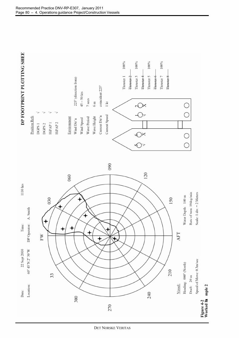
7/26/2019 DNV Rules for DSV ON DIVING OPERATION
http://slidepdf.com/reader/full/dnv-rules-for-dsv-on-diving-operation 80/118
Recommended Practice DNV-RP-E307, January 2011
Page 80 – 4. Operations guidance Project/Construction Vessels
DET NORSKE VERITAS
F i g u r e 4 - 2
W o r k e d E x a
m p l e 2

7/26/2019 DNV Rules for DSV ON DIVING OPERATION
http://slidepdf.com/reader/full/dnv-rules-for-dsv-on-diving-operation 81/118DET NORSKE VERITAS
Recommended Practice DNV-RP-E307, January 2011
4. Operations guidance Project/Construction Vessels – Page
4.20 Annual DP Trials Test Table Blank – DP Project / Construction Vessel
Guidance note:
The blank Annual DP Trials test sheet is on hold pending formal publication of IMCA guidance on Annual DP Trials
which is under development at the time of preparing this RP. Guidance will be provided in a subsequent revision of
this RP.
---e-n-d---of---G-u-i-d-a-n-c-e---n-o-t-e---
4.21 Example of SMO and ASOG
Safest Mode of Operation - Name of DP Project/ Construction Vessel
This setup applies when the vessel is undertaking umbilical wet store at Nonsuch Offshore Facility - AFI(agreed for implementation)
Date
Condition GREEN DVISORY YELLOW RED
Notify Master, ChiefEngineer, WinchControl, OffshoreFacility and ClientsRepresentative
NO YES YES YES
ActionCONTINUE NORMAL
OPERATIONS
INFORMATIVE /CONSULTATIVE
STATUS (RISK ASSESS)
CEASEOPERATIONS
INITIATECONTINGENCY
PLAN
CEASE
OPERATIONSPREPARE TO
JETTISONUMBILICAL ONDIRECT ORDER
ONLY
Bus Ties and Bus Links All bus ties open Any other configuration
Main generatorsPort - Stbd symmetric (2 or
4 generators running)Port - Stbd assymmetric or
known deficiencies
LLC phase shifttransformer
Both connected andfunctioning correctly
Any other configuration orknown deficiencies
All GeneratorsTested at 100% at fieldarrival or in the past 6
months
Any other configuration orknown deficiencies
Emergency Generator
Set to auto start and
connect, available forimmediate use
Any other configuration orknown deficiencies
Bow Thruster 1 VSDVSD powered from Port
side onlyPowered from Stbd side
Bow Thruster 1 ServoPump
Powered from HP1 andchangeover to HP2 tested
at field arrival
Powered from HP2 orchangeover not tested or
problems found
Bow Thruster 1Tested at 50% on each ofPort and Stbd side at field
arrival
Powered from Stbd side oropposite to cooling or
operation on Stbd side nottested
Bow Thruster 3Deployed as azimuth
thruster Operating as tunnel
thruster
Thrusters 2, 3, 4 & 5Tested at 100% at field
arrivalAny known deficiencies
Thrusters 4 & 5Pitch and lube oil pumpschangeover tested at field
arrival
Not tested or problemsfound
Thrusters 4 & 5Both Steering motors/
VFD's runningSingle steering motor/VFD
running
ThrustersEmergency Stops tested at
field arrivalAny known deficiencies
Thrusters
Azimuth, speed and pitchcontrols tested for
functionality across entirerange at field arrival.
Any known deficiencies.
ThrustersAll fully operational as
above and selected to DPAny not operating or not
selected to DP
Speed of moves inside
500 m zone or carryingout critical activities
From 500 m to 200 m, <=
0.5 m/sec From 200 m towork location <=0.3 m/sec Any other setting
Rate of change ofHeading (Within 500 mzone) or carrying outcritical activities
<=10 deg/min Any other setting

7/26/2019 DNV Rules for DSV ON DIVING OPERATION
http://slidepdf.com/reader/full/dnv-rules-for-dsv-on-diving-operation 82/118DET NORSKE VERITAS
Recommended Practice DNV-RP-E307, January 2011
Page 82 – 4. Operations guidance Project/Construction Vessels
Thrust Values whenexiting500 m zone onJoystick or manual
Work location to 200 m <25% or minimum to safely
pull away from vessel200 m - 500 m <50% orminimum to pull awayoutside the 500 m zone
Approaching 25% or 50%
Thruster manual leversTested and fully
operationalAny known deficiencies.
Independent Joystick Tested and fullyoperational
Any known deficiencies.
DP SystemConsequence analysis
enabled, no alarms activeAny other configuration.
DP SystemTested and fully
operationalAny known deficiencies.
DP power supplyAll UPS units fully
functional, none operatingon bypass
Any known deficiencies. None less than 30 min.
autonomy
DP Environmentalsensors (Gyro, MRS,wind sensors)
Tested and fullyoperational
Any known deficiencies.
DP Position ReferenceSensors
All fully operationalAny other configuration or
known deficiencies.
DP Position ReferenceSensors
Three position referencesensors, using twodifferent technologies,
selected and accepted bythe DP system
Any other configuration orknown deficiencies.
DGPS DP Positionreference sensors
If two DGPS units in useset to different correctionsources and on different
elevation masks.
Any other configuration orknown deficiencies.
DGPS DP Positionreference sensors
No possibility of masking by cranes / structure
Possibility of masking bycranes / structure
Relative Pos ReferenceSystems (Fan Beam)
Operating and availableAny Alarms or poor
performance
Redundant Relative PosReference Systems
during umbilical transferoperations
Two systems (working ondifferent principles)
operational and available
Any Alarms, poor performance or non
availability of redundantrelative position reference
sensors
HiPAP Operating and availableAny Alarms or poor
performance
FrequenciesFrequencies in use planned
with other DP vessels inthe area
Not planned
RadiusFully tested on DP
alongside TLP prior to pickup and pull in of umbilical
Not tested prior
Relative PositionReference System(Fanbeam/Radius)
Operating and availableAny mix of relative and
absolute systems
Note: For this operation, given that the observedTLP movement has been minimal under the
weather criteria that umbilical transfer can beconducted, it has been accepted that a mix of
absolute and relative position reference systemsmay be permitted provided movement of TLP
has been ascertained to be not excessive. Ifunexpected movement of TLP is detected,
absolute systems to be deselected immediately.
TLP MOVEMENT(Check at 100 m off andcontinuously duringoperations)
Footprint not preventinguse of DGPS
Movement of TLP suchthat DGPS cannot be used
in conjunction withFanbeam/Radius
Fuel system
Set up as split system (allcross connecting valvesclosed). Valve positions
physically checked.
Any other configuration orknown deficiencies.
Sea water and fresh watercooling pumps
Standby pumps availableand set to auto start
Any other configuration orknown deficiencies.
Bow thruster T1
Cooled from Port FW only
and changeover to stbdchecked at field arrival
cooled from Stbd side orchangeover not checked
Power ManagementSystem
Fully operational. Any known deficiencies.

7/26/2019 DNV Rules for DSV ON DIVING OPERATION
http://slidepdf.com/reader/full/dnv-rules-for-dsv-on-diving-operation 83/118

7/26/2019 DNV Rules for DSV ON DIVING OPERATION
http://slidepdf.com/reader/full/dnv-rules-for-dsv-on-diving-operation 84/118DET NORSKE VERITAS
Recommended Practice DNV-RP-E307, January 2011
Page 84 – 4. Operations guidance Project/Construction Vessels
DP Operator ControlStation
Both operatingnormally, no alarms.
Any alarm, poor performance,unexpected or
unexplained event
Loss of one operatorstation
Dynamic positioningcontrollers
Both operatingnormally, no alarms.
Any alarm, poor performance,unexpected or
unexplained event
Loss of one DPC
PMS/IAS FieldTermination Cabinets
All operating normally,no alarms.
Any alarm, poor performance,unexpected or
unexplained event
Loss of one PLC
DP NetworksBoth operating
normally, no alarms
Any alarm, poor performance,unexpected or
unexplained event
Loss of one network Total loss of networks /
DP control
Gyros3 gyros selected and
accepted by DPAny gyro alarm.
One operational gyroremaining
MRUs2 MRUs selected and
accepted by DPAny MRU Alarm
One operational MRUremaining
Wind sensorsOperational with no
alarmsLoss of wind sensor
Loss of both windsensors in high wind/
gusting wind
conditions.
DP Position referencesensors
Three positionreference sensors, using
two differenttechnologies, accepted
by the DP system and inuse.
Any alarm, poor performance,unexpected or
unexplained event
One remainingoperational position
reference system
Redundant Relative PosReference Systems duringumbilical transferoperations
Two systems (workingon different principles)
operational andavailable
Any Alarms, poor performance or non
availability ofredundant relative position reference
sensors
Single relative pos ref
PMS/IAS Control systemsAll operating normally,
no alarms.
Any alarm, poor performance,unexpected or
unexplained event
Loss of one majorsystem component
Machinery spaceventilation, DP criticalspace Air Conditioning
Fully operational.Loss or reduced
capacity of any system
Imminent loss of due toover temperature of any
DP equipment.
Loss or problem with anyessential Communications(DP / ECR / WinchCONTROL/ROV/TLP)
RedundantCommunications
One system remaining No comms
Fire No fire alarms, or fire
reportedAny fire alarm/report Fire confirmed
Flood No bilge alarms active,
no reported flooding.Multiple bilge alarms Flood confirmed
Collision (errant vessels) No collision imminent /
minimum approach
>500 m
Minimum approachwill be < 500 m
If collision possible Collision Imminent

7/26/2019 DNV Rules for DSV ON DIVING OPERATION
http://slidepdf.com/reader/full/dnv-rules-for-dsv-on-diving-operation 85/118DET NORSKE VERITAS
Recommended Practice DNV-RP-E307, January 2011
4. Operations guidance Project/Construction Vessels – Page
SIMOPS - Name of DP Project/ Construction Vessel - undertaking umbilical wet store at Nonsuch TLP
Condition GREEN ADVISORY YELLOW RED
Notify Master, Chief Engineer,Winch Control, Offshore Facilityand Clients Representative
NO YES YES YES
ActionCONTINUE NORMAL
OPERATIONS
INFORMATIVE /CONSULTATIVESTATUS (RISK
ASSESS)
CEASE TYING INOPERATIONSINITIATE
CONTINGENCYPLAN
CEASE
OPERATIONSPREPARE TOJETTISON
UMBILICAL ONDIRECT ORDER
ONLY
Change from Green DP Status ofany other vessel in the field
Green Advisory Advisory Advisory
Procedure agreed and understood by all involved. Toolbox talks andsafety briefings complete.
Briefings complete.Operation continues
without major deviationfrom planned procedure.
Major deviation from procedure
Situation arises wherethe risk of personnelinjury or a pollution
event can beenvisaged.
Comms/interaction with othervessels
Vessels operatingnormally with no
known problems
Comms problemor
Possible position
conflict
No comms or
Definite position
conflict
Comms between DP Desk, Pipelay control, Deck Forman, TLPPlatform rigger foreman.
Redundant comms Comms problemOne comms system
remaining
Comms with Field Control Room Redundant comms Comms problemOne comms system
remaining
Completed by
Printed name
On behalf of Client
Printed name

7/26/2019 DNV Rules for DSV ON DIVING OPERATION
http://slidepdf.com/reader/full/dnv-rules-for-dsv-on-diving-operation 86/118DET NORSKE VERITAS
Recommended Practice DNV-RP-E307, January 2011
Page 86 – 5. Operational guidance Logistic Vessels
5. Operational guidance Logistic Vessels
5.1 Introduction
This chapter contains DP operational guidance, specific for Project and Construction Vessels. For overviewand full appreciation, this information is completed with the general management information as already wasgiven in chapter 2. For distinction, the general information is printed in regular text, and the specific operationalguidance is in italics and/or grouped under Guidance notes.
It is acknowledged that the guidance provided on the themes in this chapter may be to a greater level of detailthan what is required for logistics vessels. This has been consciously done with a view to enhance awarenessof issues related to DP operations and cover a broader DP community.
5.2 DP Operational Documentation
5.2.1 General
It is recommended that DP vessel owners/ operators should maintain the documentation listed in the table below and should develop and implement associated processes for the purposes of:
— ensuring the safe and effective management of the vessel in DP — ensuring the technical suitability of the vessel for each DP activity it is required to carry out — determining the configuration for the safest mode of operation and the task appropriate mode
— understanding the vessel’s station keeping capabilities following the worst case failure — ensuring compliance with appropriate standards and guidelines — providing training and familiarization material to vessel crews.
5.2.2 Recommended Documentation
Current versions of the documents in the list below should be kept on board and, in addition, where feasible, atthe shore based centers of technical management. Documents that have been superseded should be clearlymarked and kept separate from current versions. Documents may be in electronic or, hard copy format or, both.
No. Document Management Guidance Operational Guidance
1 DP System FMEAor FMECA
To be kept up to date, incorporating allmodifications and additions sinceoriginal study, if not in the document
itself, then by other traceable means. Allrecords to be kept on board.
Modifications and additions should be covered by a MOC process that triggers updating the FMEA.
2 DP FMEA ProvingTrials
To be conducted to prove initial DPFMEA and at other times to provemodifications and additions to the DPsystem. DP FMEA Proving Trialsshould be repeated every five years.Findings and recommendations to beaddressed in accordance with theircriticality. All records to be kept on
board.
Modifications and additions that should be provenby testing include all those that have directly effector, potential to affect the performance orredundancy of the DP system. This will include
protective, detection and monitoring functions.
3 Annual DP Trials To be conducted annually. Findings andrecommendations to be addressed inaccordance with their criticality.
Previous trials reports and associatedclose out documentation to be kept on board.
The tests in the Annual DP Trials should bedesigned to prove system redundancy, as defined inthe DP FMEA, system and equipment performance
and functionality, to validate repairs and preventivemaintenance, to test the operation of protection anddetection devices and responses so as todemonstrate that the vessel’s DP system remains fit
for purpose.
4 DP CapabilityPlots
Hard copy DP Capability Plots relevantto the vessel’s areas of operations to bereadily accessible to DPOs at the DPcontrol location.
Capability plots to be validated/ recalculated, asrequired, to ensure that they are suitable for theenvironmental conditions where the DP operationsare to take place, in particular in respect of current
speeds. This requirement to validate/ recalculateapplies also in cases where DP vessel performanceis affected by operational constraints imposed bythe activity, such as in the case of a pipelay vesselwith horizontal loads, logistics vessels retrofittedwith additional accommodation modules
(temporary or permanent).5 DP Footprints Hard copy DP Footprint Plots to be
taken by DPOs. See Note 1 at end oftable.
DP Footprint Plots should be taken regularly invarious power/ thruster combinations, including
fully intact and worst case failure and also invarious environmental conditions.

7/26/2019 DNV Rules for DSV ON DIVING OPERATION
http://slidepdf.com/reader/full/dnv-rules-for-dsv-on-diving-operation 87/118DET NORSKE VERITAS
Recommended Practice DNV-RP-E307, January 2011
5. Operational guidance Logistic Vessels – Page 87
6 Service reportsconcerning the DPsystem
Complete history of service reports to be filed and kept on board
There should be a process where the open items arehighlighted, tracked and closed out.
7 Details of all DPrelatedmodifications and
additions
Records of all DP related modificationsand additions to be kept on boardcomplete with interface and testing
information.See Note 2 at end of table.
A structured FMEA and Proving Trials approach should be used to integrate modifications andadditions into the existing DP system and its
associated equipment. New and modified software should be subjected to athorough validation process, especially to avoid theacceptance of erroneous values. Known instancesas examples pipe tensioner software that accepted a
sudden increase of pipe tension from 100 t to 300 t(erroneous input), software for thruster control thatincreased the command to the thruster to match the
faulty feedback. It is not enough to focus on the functionality ofmodifications and additions. It is equally importantto fully understand the functional design spec andthe dependencies and consequences of fault or
failure.
8 Vessel auditreports and DPaudits andinspection reports.
Complete history of all audit reports, DPaudits and inspection reports, includingfindings and close outs to be kept on
board
There should be a process where the open items arehighlighted, tracked and closed out.
9 DP OperationsManual
Vessel Specific DP OperationsManual 1), to be readily accessible at theDP control location and used by theDPOs as a reference for conducting DPoperations.
It is recommended that owners/ operators develop a standardised table of contents for vessel specific DPOperations Manuals in their fleet.
Modifications and amendments to the DPOperations Manual should be subject to MOC
processes, including changes to vessel specificchecklists.
10 DP IncidentReports
Records of all DP station keeping andother DP related incidents to be kept on
board, including investigation recordsand close outs.
All DP incidents should be investigated to an extentthat reflects the potential consequences of theincident.
11 DP Mobilization/DP Field Arrival/Trials Procedures(Bridge and EngineRoom)
Records of DP Mobilization Trials andDP Field Arrival Checklists to be kepton board for the period set by the owner/operator and, where relating to a DPincident permanently stored inretrievable archives.
DP Trials and Checklists should be vessel specificand be developed from detailed informationcontained in the DP FMEA. They should confirmvessel performance, particularly following worstcase failure, and that the vessel’s DP system is setup properly and provides the required level ofredundancy.
12 DP Location andWatchkeepingchecklists(Bridge and EngineRoom)
Records of all DP Location andWatchkeeping Checklists to be kept on
board for the period set by the owner/operator and, where relating to a DPincident, permanently stored inretrievable archives.
As above
13 DP related drills
and emergencyresponse drills
Records of DP related drills and
emergency response drills to be kept on board in retrievable archives.
DP drills can be developed from fault and single
point failure scenarios addressed in the vessel’s DP FMEA.The drills should also cover extreme events that areoutside the scope of the DP FMEA.The outcomes from these drills should be used in thedevelopment of DP emergency response proceduresand used as training material for DP personnel.These records may be used in a cycle of continuousimprovement.
14 DP fault log Records of all faults related to the DPsystem to be kept on board permanentlyin retrievable archives.
DP faults should be recorded as soon as possibleafter they are discovered and action/ investigationtaken appropriate to the potential consequences ofthe fault on the vessel’s station keeping ability.
No. Document Management Guidance Operational Guidance

7/26/2019 DNV Rules for DSV ON DIVING OPERATION
http://slidepdf.com/reader/full/dnv-rules-for-dsv-on-diving-operation 88/118DET NORSKE VERITAS
Recommended Practice DNV-RP-E307, January 2011
Page 88 – 5. Operational guidance Logistic Vessels
Note 1: It is acknowledged that DP Footprint Plots may be less relevant for DP MODUs than for other DPvessel types.
Note 2: Owners/ operators should keep adequate records and documentation relating to modifications andadditions that could have an effect on the DP system, especially interfaces between equipmentfrom different vendors. This is as relevant for equipment whose primary function lies outside theDP system, such as an Emergency Shutdown Systems (ESD), pipe tensioner systems and firemonitor systems as it is for DP equipment, such as propulsion, position references and sensors.All modifications and additions should be subjected to FMEA type analysis and undergo ProvingTrials type testing. In addition, modifications and additions are typically subject to class approval
and inspection.
15 DP Data Logging Where the vessel has DP data loggingfacilities electronic records should bekept on board for the period set by theowner/ operator and, where relating to aDP incident, permanently stored inretrievable archives.
DP data loggers perform an important function inhelping to determine root causes of faults or
failures. It is recommended that DP data logging function isincluded as part of the DP system design spec,
DP data loggers should be commissioned and
operational before DP system Customer Acceptance Trials (CAT) are carried out.The DP data logger should be incorporated in theSMO and running at all times when in DP. If not,this should trigger an Advisory condition, i.e.
BLUE.There should be specific procedures for theoperation and analysis of output from the DP datalogger. This should include clear instructions onhow and where the records are kept.
Retention of data logging data should not be limitedby time.
Note:- It is acknowledged that DP data loggers arenot the norm on Logistics vessels. Owners areencouraged to consider the benefits to be derived by
installing DP data loggers on their vessels.16 DP alarm printer
readoutsHard copy records of the DP alarm
printer readout to be kept on board forthe period set by the owner/ operatorand, where relating to a DP incident,
permanently stored in retrievablearchives.
Owners/ operators frequently require DP alarm printer readouts to be kept for a duration indicatedin their Management Systems. Where this is not
specified, owners are encouraged to specifyretention times, Alarm printouts relating to a DPincident or contractual dispute are to be
permanently stored in retrievable archives.
17 DP familiarisationand competencyrecords
All records relating to vessel specificDP familiarisation and competency forDPOs, engineers and electricians to bekept on board permanently inretrievable archives.
Owners/ operators should implement an in-house DP competency assurance process for key DP personnel which is structured, systematic and progressive. It should be noted that DPOcertification is only one element in the competencyassurance process.
Owners/ operators are recommended to make use of facilities and training programmes available to the DP sector, such as the Powersim program foradvanced DPO training of power plant faultconditions, where DPOs are given detailedinstruction and training in identifying andresponding to power system faults. Examplesinclude DPO intervention averting anunderfrequency induced blackout on closed bus
system by the DPO taking control of thrusters andbiasing to increase load.
18 Résumés andvessel specificwork records of allkey DP personnel
Résumés of all key DP personnel,copies of certification andqualifications, records of DPwatchkeeping hours to be maintained on
board. Original DPO certificates and DPLog Books to be held by the DPOsonboard the vessel.
1) The vessel specific DP Operations Manual is additional to the DP control system manufacturer’s Operator Manual
No. Document Management Guidance Operational Guidance

7/26/2019 DNV Rules for DSV ON DIVING OPERATION
http://slidepdf.com/reader/full/dnv-rules-for-dsv-on-diving-operation 89/118DET NORSKE VERITAS
Recommended Practice DNV-RP-E307, January 2011
5. Operational guidance Logistic Vessels – Page 89
5.3 DP Class
It is recommended that DP vessels with at least the following DP equipment class notations are used for thefollowing activities. Regulations, contractual specifications and/ or harsh environmental or other localconditions may require a higher class.
Note 1: The vessel’s DP system should normally be set up and operated to deliver the intent of the DPclass notation. However, on occasion and after a proper assessment of the risks, the vessel may beset up in accordance with the requirements of the Task Appropriate Mode.
Note 2: For operations close to another vessel or installation the equipment class should be 3 or equivalent.Class 2 may be accepted based on considerations of procedures, equipment and consequenceanalysis
Note 3: It is noted that there have been standards developed outside the IMO DP equipment classsystematics where an identical (or higher) level of redundancy has been realized based on adifferent philosophy and system approach.
Guidance note:
A detailed risk analysis will be required if the vessel is to operate in a task appropriate mode (TAM) that providesless redundancy than that provided by the vessel’s DP equipment class notation.
The detailed risk analysis should consider the consequences of loss of position relevant to the activity.
---e-n-d---of---G-u-i-d-a-n-c-e---n-o-t-e---
5.4 DP FMEA
The DP vessel’s DP FMEA is the most important technical document in the list of required documents. The
requirement for a DP FMEA has its origins in IMO MSC/Circ 645 (1994) “Guidelines for Vessels withDynamic Positioning Systems”. These benchmarking guidelines provide the foundation for all subsequent DPrules, regulations and guidance issued by Class and other industry bodies, such as IMCA.
The IMO Guidelines require all DP vessels to be subjected to survey and testing in accordance with IMO’sspecified guidelines. This includes initial and periodic complete survey and testing of all systems andcomponents required to keep position after single failures associated with the vessel’s assigned DP equipmentclass.
The periodic component in the IMO Guidelines requires the complete survey and testing to be repeated everyfive years to ensure full compliance with applicable parts of the guidelines.
In addition compliance with IMO Guidelines requires survey and testing after defects are discovered andcorrected and, after a DP related accident and, whenever significant repairs or alterations are carried out, so asto demonstrate full compliance with applicable parts of the guidelines.
The IMO Guidelines do not make clear distinction between vessels of different DP equipment class.This IMO requirement has been interpreted by the DP community such that the survey requirement is met bya DP FMEA (or FMECA1)) and the testing requirement by DP FMEA Proving Trials.
1) Unless expressly stated in this Guidance document a FMECA is interchangeable with an FMEA.
Application on DP
Minimum Recommended DP
Equipment Class(See Note 1 below)
Remarks
Drilling 2
Diving 2
Pipelay 2
Umbilical Lay 2
Lifting 2
Accommodation 2
Shuttle Offtake 2
ROV Support (Open Water) 1
ROV Support (Close Proximity -Surface/ Subsea)
2
Floating Production 2
Seismic and Survey vessels (Openwater- outside 500 m zone)
** ** Class in accordance with contractual requirements
Well Stim 2* * Vessels of lesser Class may be used with theappropriate structured risk identification andmitigation measures in place.
Logistics Operations 2*

7/26/2019 DNV Rules for DSV ON DIVING OPERATION
http://slidepdf.com/reader/full/dnv-rules-for-dsv-on-diving-operation 90/118DET NORSKE VERITAS
Recommended Practice DNV-RP-E307, January 2011
Page 90 – 5. Operational guidance Logistic Vessels
Accordingly, all DP vessels of DP Class 2 or 3 are required to have a Class approved and stamped DP FMEAand DP FMEA Proving Trials.
Definitions: An FMEA is a systematic analysis of systems and sub-systems to a level of detail that identifiesall potential failure modes down to the appropriate sub-system level and their consequences. AFMECA is an extension of an FMEA that adds a risk assessment of each failure mode to determineits criticality.
In addition to complying with the IMO Guidelines and the relevant DP rules of the vessel’s Classification Societythe DP FMEA should achieve the standards of detail and analysis contained in the following industry guidance;
— IMCA M166 “Guidance on Failure Modes and Effects Analysis” — IMCA M178 “FMEA Management Guide” — IMCA M04/04 2004 “Methods of Establishing the Safety and Reliability of DP Systems”
Note: FMEAs are a requirement to obtain DP Class 2 and 3 notation. Whilst not stipulated as a classrequirement for DP 1 vessels owners/ operators are encouraged to subject their DP 1 vessels to theDP FMEA process.
Note: Particular attention should be paid in the DP FMEA to the interfaces between the DP system andother systems that have the potential to affect the DP system, such as where the vessel is fittedwith an Emergency Shut Down (ESD) system, pipe tensioner system or fire monitor system.
Key DP personnel, including the vessel Master, DPOs, Engineers and Electricians should have a detailedknowledge of the DP FMEA and should use the information provided to be fully informed about thecapabilities and limitations of the vessel’s DP system.
The results from a DP FMEA, in particular issues related to the vessel’s worst case failure and significant single point failures, should be used in the formulation of operational, emergency response and planning decisions.
Guidance note:
These Guidance Notes on DP FMEAs are intentionally brief. They give a concise overview of the underpinning philosophy, analytical processes and the technical content of a DP FMEA. Relevant IMCA guidance, referred to inthis section, should be consulted to gain a more detailed understanding.
A DP FMEA should encompass the following:-
— identify worst case failure design intent (WCFDI) and worse case failure (WCF), — identify the equipment or subsystem, mode of operation and the equipment, — Identify all potential failure modes and their causes,
— identify the significant single point failures, — identify potential hidden failures, — identify potential configuration errors, — evaluate the effects on the system of each failure mode, — Identify measures for eliminating or reducing the risks associated with each failure mode, — identify trials and testing necessary to prove the conclusions, — be updated after any major modifications and proving trials have been conducted, — be subject to review and update as necessary, once every five years. The review should take account of new
equipment and hardware/ software updates, new developments in analysis and new knowledge acquired in theintervening period,
— take account of action items from DP FMEA Proving Trials, Annual DP Trials, audits and incidents which havebeen or, are in the process of being, closed out,
— take account of non DP systems/ auxiliary/ external systems that have interfaces with, and potential impact on DP and station keeping. These systems should be subjected to the FMEA and Proving Trials approach for
software, hardware and interfaces thus ensuring the integrity of the DP system and proper integration with DP, — take account of common mode failures that are otherwise liable to be overlooked, such as the effects of hydrocarbon gas on engine control and safety systems, which can cause diesel engines to accelerate out of control resulting in catastrophic mechanical failure and potential for black out.
— be presented as a narrative analysis of DP related systems and subsystems covering the above points (i.e.redundancy concept, hidden failures, configuration errors, etc.) and be supported by sketches and drawings,
— for DP Class 3 vessels, should consider the effects of fire and flood, not only from a compartment analysis perspective but also, where significant, at the subsystem level, e.g. the effects of fire and flood on ESD control lines and push buttons.
Note: Where the redundancy concept relies on inter-switching mechanisms, the reliability and effectivenessof these mechanisms should be proven and fully documented in the DP FMEA.
Note: The DP FMEA should contain an analysis of the DP control system I/Os to verify that it is consistent with the redundancy concept and should be proved at DP FMEA Proving Trials.
Note: The DP FMEA should address the ESD function (if fitted), in particular the various issues relating to
the status of post activation battery power supplies (UPS). Appropriate guidance is given in section 6.6 of IMCA M196, “Guidance on the Design, Selection, Installation and Use of UPS onboard Vessels”.
Note: The findings from a DP FMEA and Proving Trials should be categorised into A, B or C. Categories should be clearly defined. Appropriate definitions are as follows;
A For immediate attention. The failure effect exceeds worst case failure design intent or is non

7/26/2019 DNV Rules for DSV ON DIVING OPERATION
http://slidepdf.com/reader/full/dnv-rules-for-dsv-on-diving-operation 91/118DET NORSKE VERITAS
Recommended Practice DNV-RP-E307, January 2011
5. Operational guidance Logistic Vessels – Page 91
compliant with specified rules and guidelines, e.g. Class rules. Improvement is required for compliancewith class.
B For attention when reasonably convenient. The failure effects equal worst case failure design intent but there is an opportunity to reduce the failure effect as reasonable cost. A cost benefit analysis isrecommended.
C For consideration. Comments and observations related to good practice.
A FMECA is an extension of an FMEA that adds a risk assessment of each failure mode to determine its criticality.
Criticality is derived from an assessment of the probability that a particular failure will occur combined with the severity of the failure if it does occur.
A DP FMECA should encompass all of the listed points in DP FMEA above and, in addition, include the following steps;
— determine the severity of each failure mode, — determine the probability of occurrence of each failure mode (using qualitative or reliable MTBF data), — determine and rank the criticality of the identified failure modes from highest to lowest, — determine a strategy for dealing with the ranked criticalities so that remedial measures are directed
appropriately in accordance with the criticality ranking,
The Criticality Analysis should be presented in tabulated form making using of risk matrices that comply withrecognised international standards such as those given in IMCA M166 or IEC 60812.
Note: The closing out of action items should be well documented and auditable.
The following IMCA Guidelines address the above considerations in various levels of detail; M166, M178, M04/04and Annex.
A DP FMEA should be referred to at the following times;
— conducting task based DP operational risk assessments, where key personnel involved should have detailed knowledge of the DP FMEA,
— determining the DP vessel’s Safest Mode of Operation (SMO), e.g. where the unavailability of equipment mayreduce the vessel’s DP station keeping ability,
— determining the DP vessel’s Activity Specific Operating Guidelines (ASOG), e.g. where equipment performanceapproaches or exceeds predetermined limits,
— determining the vessel’s Task Appropriate Mode, when applicable and warranted by the specific DP operations, — developing planned maintenance schedules, taking account of the impact of taking systems or equipment out of
service — developing the vessel’s DP Operations and Emergency Response manuals and procedures,
— developing DP trials programs and checklists, ensuring that the single point failures identified in the DP FMEAare covered in the trials and checklists.
Note to Owners: In the case of newbuilds, if DP FMEAs are within the shipyard’s scope of supply, owners arerecommended to ensure that there are contractually binding agreements for the FMEA to meet
specifications set out in IMCA Guidelines, M166. M178, M04/04 and Annex and preferably becarried out by an independent third party DP FMEA practitioner.
Cautionary Note: DP FMEAs that are solely focused on attaining class notation and class approval may not always meet guidance standards stipulated in those IMCA Guidelines.
---e-n-d---of---G-u-i-d-a-n-c-e---n-o-t-e---
5.4.1 DP Capability Plots
DP Capability Plots should be calculated for the vessel. Guidance is provided on DP Capability Plots in IMCAM140 Rev 1, “Specification for DP Capability Plots”.
These theoretical plots are calculated from detailed information of the vessel’s hull and superstructure form andavailable thruster power. The calculations should use environmental data (seastate, wind and current)appropriate to the area in which the DP vessel is to operate.
These plots should show the limiting wind speed 360 degree envelopes for the scenarios below, where each point on the envelope represents the wind speed at which it is calculated that the vessel will be unable tomaintain position in DP.
DP Capability Plots should include the following scenarios at current speeds of 0, 1 and 2 knots, or at other current speeds that are representative of the location in which the DP vessel is to operate:
— Fully intact power generation and thrusters. — Loss of most effective thruster(s). — Following the worst case failure.
Note: The DP Capability Plots should be provided in a format that is intuitive to the user on board (e.g.Polar Plot).
Guidance note:
DP Capability Plots that do not cover Worst Case Failure are incomplete. DP Capability Plots that do not take into

7/26/2019 DNV Rules for DSV ON DIVING OPERATION
http://slidepdf.com/reader/full/dnv-rules-for-dsv-on-diving-operation 92/118DET NORSKE VERITAS
Recommended Practice DNV-RP-E307, January 2011
Page 92 – 5. Operational guidance Logistic Vessels
account thruster interaction, (thruster-thruster, thruster-hull), thruster degradation and thruster barred zones areincomplete.
Owners/ operators should note that it is important to provide a detailed scope of work to whoever is to generate the DP Capability Plots for the vessel. Experience has shown that those who generate the DP Capability Plots, such asthe DP system manufacturers, may not include the Worst Case Failure, unless specifically instructed to do so. This is
particularly relevant where the DP Capability Plots are included in the shipyard’s scope of supply for newbuilds.
DP Capability Plots may have to be recalculated from time to time during the lifetime of a DP vessel. For example,
the installation of new equipment, such as a crane or an accommodation module on deck will alter the vessel’s outline,which, in turn, will alter the wind effect on the vessel. In these circumstances the DP Capability Plots should be re-calculated to take account of the changes.
DP Capability Plots may also have to be recalculated for thruster configurations where, due to unforeseen faults or failures or, due to essential maintenance requirements, one or more thrusters are no longer available. Where not already covered by existing calculations the revised DP Capability Plots should cover the following cases for the newthruster condition; i.e. the new fully intact condition, the new loss of most effective thruster(s) and the new worst case
failure condition.
DP Capability Plots should be readily available to the DPOs at the DP control console.
DPOs should consult DP Capability Plots as a matter of course whilst the vessel is conducting DP operations.
DPOs should be fully familiar with the limits given in the DP Capability Plots for the fully intact thruster configuration, for loss of most effective thruster and for worst case failure.
DPOs should be careful when estimating the current force acting on the vessel and relating it to the DP Capability Plots. DPOs should be aware that the current force generated by the DP control system is the residual external forceacting on the vessel that cannot be measured. When wind speeds are low an attendant vessel, if available, could beused to estimate current by going into drift mode.
DP Capability Plots should be used by DPOs and other key DP personnel as a reference in the planning phases whendetermining the vessel’s environmental operational limits for the ASOG. Where the DP Capability Plots show anundue level of heading limitations this may restrict the vessel’s operating range. This is not uncommon on vessels,
such as DP tankers, that have good fore and aft thrust capability but limited thwartship capability.
It should be remembered that DP Capability Plots are theoretical calculations and that, wherever possible,opportunities should be taken to validate the DP Capability Plots by taking DP Footprint Plots. See below.
---e-n-d---of---G-u-i-d-a-n-c-e---n-o-t-e---
5.5 DP Footprint Plots
DP Footprint Plots should also be produced on board. DP Footprint Plots are not theoretical. They are actual
measurements of the vessel’s DP station keeping performance in the actual environmental conditions andthruster configuration at the time the plot was taken. DP Footprint Plots should be taken whenever opportunitiesarise, such as during standby periods, weather downtime or on arrival at the field. Plots should be taken for thethruster configurations used in the DP Capability Plots, i.e. fully intact, loss of most effective thruster(s) andafter worst case failure.
Some DP systems have a software application that produces DP Footprint Plots electronically. DPOs can also produce DP Footprint Plots by manual methods using a plotting sheet.
DP Footprint Plots serve two main purposes.
— They provide a scatter plot of vessel positions at regular intervals around the required set position (thisshows accuracy of station keeping)
— They also provide comparison points on the limiting wind speed envelope given in the theoretical DPCapability Plots (this shows wind speeds at which it was seen that the vessel was unable to maintain
position, thus validating or contradicting the theoretical DP Capability Plots for the various thruster configurations.)
DP Footprint Plots serve other purposes, including learning and familiarisation opportunities for DPOs and in providing snapshots of vessel station keeping behaviour for specific locations and activities.
Theoretical DP Capability Plots and DP Footprint Plots combine together to enhance knowledge andunderstanding of the vessel’s DP station keeping ability.
Note: DP Footprint Plots originated in harsh weather regions, such as in the North Sea. The plots areused to gain a better understanding of the vessel’s actual station keeping performance andlimitations in intact and, in various degraded thruster configurations, including worst case failure,whilst the vessel is being subjected to real environmental forces.
It is acknowledged that DP Footprint Plots may be of less relevance to DP MODUs.
Guidance note:
Manual DP Footprint Plots are generated in the following manner.
— Use a proforma plotting sheet, comprising a 360 degree polar plotting diagram, vessel outline with thrustersindicated and space for vessel specific position reference systems and environmental data. Refer to plotting sheetsin Sec. 5.19.

7/26/2019 DNV Rules for DSV ON DIVING OPERATION
http://slidepdf.com/reader/full/dnv-rules-for-dsv-on-diving-operation 93/118DET NORSKE VERITAS
Recommended Practice DNV-RP-E307, January 2011
5. Operational guidance Logistic Vessels – Page 93
— The vessel should be in auto DP. Record wind, waves and current on the plotting sheet, drawing appropriate vectors.
— Record thruster configuration on the plotting sheet.
— Record the rate of turn and speed of moves. It is suggested that the following values are applied, 10 deg/min and 0.3 m/sec, respectively, to prevent misleading results.
— Observe position excursions from the intended position by the most appropriate means, plotting the vessel’s position regularly, e.g. every 30 seconds.
Sec.5.19 contains two worked examples. Both worked examples are for the same DP vessel and in the sameenvironmental conditions. Wind was 45 to 50 knots from 225 degrees with a corresponding wave height of 6 m.Current was 1 coincident at 1 knot.
Example 1 shows a DP Footprint Plot for the vessel’s fully intact condition with all four thrusters operational. The plot shows that the vessel was able to maintain position within +/- 2 meters with the wind and sea on the port quarter.
Example 2 shows a DP Footprint Plot for the vessel’s worst case failure condition with only two thrusters operational.The plot shows that the vessel was unable to maintain position with the wind and sea on the port quarter.
Example 2 - The known circumstances at the time of taking the DP Footprint Plot, of wind, wave height and thruster configuration, in which the vessel failed to maintain position, can be compared against the environmental envelope
plotted on the theoretical DP Capability Plot for worst case failure. They should be similar in that the DP Capability Plot should also show that vessel will be unable to maintain position in conditions where a 45 to 50 knots wind is onthe port quarter. If there is a significant difference between the two, particularly if the DP Capability Plot shows that the vessel can maintain position in the given condition, then it may be necessary to pull in the limiting wind envelopeon the DP Capability Plot to the upper wind speed determined by the DP Footprint Plot for these conditions.
Cautionary Note: The DP Footprint Plot positions will contain systematic position reference errors.
---e-n-d---of---G-u-i-d-a-n-c-e---n-o-t-e---
5.6 Position Reference Systems and Sensors
The DP vessel should be equipped with suitable position reference and sensors in accordance with the vessel’sDP class notation and operational requirements. Position reference systems should be selected with dueconsideration to operational requirements, both with regard to restrictions caused by the manner of deploymentand expected performance in working situations.
Position reference systems comprise absolute and relative systems. An absolute system gives vessel
geographical position. A relative system gives vessel position in relation to a non-fixed reference. A relativesystem can be used as an absolute system if installed on a point that is a fixed geographical position. And, anacoustic absolute system can be used as a relative system if attached to a non-fixed asset.
The following are the most common position reference systems in use.
Note 1: Class rules give minimum requirements for the number of position references. Where operationaluptime is one of the key success factors the benefit gained by consciously exceeding the minimumrequirements are to be evaluated. Other benefits of exceeding minimum requirements includegreater redundancy and improved station keeping performance.
Note 2: It could be debated that Taut Wire and Acoustic Position reference systems are relative positionreference systems. For purposes of this document, absolute indicates that this position referencesensor is independent of another fixed or floating offshore structure.
Caution: Additional position reference systems should be based on different principles. It is generally notrecommended to use multiple (>2) satellite based systems in conjunction with other positionreference systems as this may result in skewed weighting in favour of multiple satellite systems.
Caution: DP reference systems sensitive to interferences from the vessels radars, radios etc. should not be
used during critical operations such as sub-sea operations.
Guidance note:
The reference system may be subject to contract specifications/ oil major requirements. Notwithstanding these,operational guidance on position reference systems and sensors is given in the table on the next page.
Absolute DGNSS (DGPS and GLONASS)
Acoustic (USBL, SBL, LBL)
Taut wire (see Note 2)
Relative Artemis
Laser (e.g. Fanbeam, Cyscan)
Radar (e.g. RADius, RadaScan)
DARPS

7/26/2019 DNV Rules for DSV ON DIVING OPERATION
http://slidepdf.com/reader/full/dnv-rules-for-dsv-on-diving-operation 94/118
Recommended Practice DNV-RP-E307, January 2011
Page 94 – 5. Operational guidance Logistic Vessels
DET NORSKE VERITAS
R e c o m m e n d e d A b s o l u t e P o
s i t i o n R e f e r e n c e S y s t e m s
R e c o m m e n d e d R e l a t i v e P o s i t i o n R e f e r e
n c e s S y s t e m s i f i n c l o s e p r o x i m i t y t o a n
o f f s h o r e
s t r u c t u r e
S e n s o r s
A p p l i c a t i o n o n
D P
G P S
D G N S S
( D G P S +
G L O N A S S )
( S e e N o t e 2
b e l o w )
S B L ( S e e
N o t e 1
b e l o w )
U S
B L /
S S B L
( S e e
N o t e 1
b e l o w )
L B L
( S e e
N o t e 1
b e l o w )
T a u t
W i r e
( S e e
N o t e 1 2
b e l o w )
M i n
N u m b e r
( S e e
N o t e 3
b e l o w )
A r t e m i s
L a s e r
R a d a r
G a n g w a y
D A R P
S
M i n F i x e d
p l a t f o r m
( S e e N o t e s
4 , 5 & 6
b e l o w * )
T L P / S P A R /
e t c < m i n
m o v e m e n t
( S e e N o t e s 4 ,
5 & 6 b e l o w * )
T L P / S P
A R /
e t c > m
i n
m o v e m
e n t
( S e e N o t e s 4 ,
5 & 6 b e l o w * )
G y r o s , V R U s
a n d W i n d
S e n s o r s ( S e e
N o t e 7 b e l o w )
D r i l l i n g
I f i n
d e e p
o p e n
w a t e r
R e d u n d a n t -
o n e d u a l
f r e q u e n c y
< 7 0 0 m
< 7 0 0 m
> 7 0 0 m
< 3 5 0 m
3
Y
Y
Y
N
N
3 m i x e d
a b s & r e l
3 m i x e d a b s &
r e l
3 r e l a t i v e
o n l y
3
D i v i n g
N
Y
< 7 0 0 m
< 7 0 0 m
> 7 0 0 m
< 3 5 0 m
3
Y
Y
Y
N
N
3 m i x e d
a b s & r e l
3 m i x e d a b s &
r e l
3 r e l a t i v e
o n l y
3
P i p e l a y
N
Y
N
N
N
N
3
Y
Y
Y
N
N
3 m i x e d
a b s & r e l
3 m i x e d a b s &
r e l
3 r e l a t i v e
o n l y
3
U m b i l i c a l L a y
N
Y
N
N
N
N
3
Y
Y
Y
N
N
3 m i x e d
a b s & r e l
3 m i x e d a b s &
r e l
3 r e l a t i v e
o n l y
3
R i s e r P u l l i n
N
Y
< 7 0 0 m
< 7 0 0 m
> 7 0 0 m
< 3 5 0 m
3
Y
Y
Y
N
N
3 m i x e d
a b s & r e l
3 m i x e d a b s &
r e l
3 r e l a t i v e
o n l y
3
L i f t i n g
N
Y
< 7 0 0 m
< 7 0 0 m
> 7 0 0 m
< 3 5 0 m
3
Y
Y
Y
N
N
3 m i x e d
a b s & r e l
3 m i x e d a b s &
r e l
3 r e l a t i v e
o n l y
3
A c c o m m o d a t i o n
N
Y
< 7 0 0 m
< 7 0 0 m
> 7 0 0 m
< 3 5 0 m
3
Y
Y
Y
Y
N
3 m i x e d
a b s & r e l
3 m i x e d a b s &
r e l
3 r e l a t i v e
o n l y
3
S h u t t l e O f f t a k
e
N
Y
N
N
N
N
3
Y
Y
Y
N
Y
3 m i x e d
a b s & r e l
3 m i x e d a b s &
r e l
3 r e l a t i v e
o n l y
3
R O V S u p p o r t
N
Y
< 7 0 0 m
< 7 0 0 m
> 7 0 0 m
< 3 5 0 m
2
N
N
N
N
N
*
*
* S e e N o t e 8
b e l o w
2
F l o a t i n g
P r o d u c t i o n U n
i t
N
Y
< 7 0 0 m
< 7 0 0 m
> 7 0 0 m
< 3 5 0 m
3
N
N
N
N
N
N A
N A
N A
3
W e l l S t i m
N u n l e s s
o p e n
w a t e r
Y
< 7 0 0 m
< 7 0 0 m
> 7 0 0 m
< 3 5 0 m
2
Y
Y
Y
Y
Y
2
*
*
2
O S V S n a t c h
L i f t s
N
Y
< 7 0 0 m
< 7 0 0 m
> 7 0 0 m
< 3 5 0 m
2
Y
Y
Y
N
N
1
2 m i x e d a b s
a n d r e l
2
2
O S V H A Z M A
T
T r a n s f e r n o
q u i c k d i s c o n n e c t
N
Y
< 7 0 0 m
< 7 0 0 m
> 7 0 0 m
< 3 5 0 m
3
Y
Y
Y
Y
N
2
3 m i x e d a b s &
r e l
3 r e l a t i v e
o n l y
3
O S V H A Z M A
T
T r a n s f e r w i t h
q u i c k d i s c o n n e c t
N
Y
< 7 0 0 m
< 7 0 0 m
> 7 0 0 m
< 3 5 0 m
2
Y
Y
Y
Y
N
2
*
*
3
O S V w i t h s h a f t
g e n s a n d s i n g l e
s t e r n t h r u s t e r
N
Y
< 7 0 0 m
< 7 0 0 m
> 7 0 0 m
< 3 5 0 m
2
Y
Y
Y
Y
Y
3
*
*
3
W i n d T u r b i n e
i n s t a l l a t i o n
N
Y
N A
N
A
N A
N A
2
N
N
N
N
N
N A
N A
N A
2
S t a n d b y V e s s e l s
Y
Y
< 7 0 0 m
< 7 0 0 m
> 7 0 0 m
< m
1
N
N
N
N
N
N A
N A
N A
1 o r <

7/26/2019 DNV Rules for DSV ON DIVING OPERATION
http://slidepdf.com/reader/full/dnv-rules-for-dsv-on-diving-operation 95/118DET NORSKE VERITAS
Recommended Practice DNV-RP-E307, January 2011
5. Operational guidance Logistic Vessels – Page 95
Note 1: (Acoustics) – The acoustic LUSBL system is not included in the above table since it is a combination of USBL and LBL in one system, where the USBL is typically used to calibrate the LBL system.
The abbreviations, USBL and SSBL, are referred to in the above table. Although the abbreviationsdiffer they both refer to the same acoustic application although supplied by different vendors.
It is recommended that, wherever possible, multiple acoustic systems are completely separated and independent in all respects. For instance, this would require the use of separate and independent hull transceivers.
Owners/ operators should consider the advantages of acoustic positioning systems that have an inertial navigation input, such as the Kongsberg HAIN (Hydro Acoustic Inertial Navigation) system or Sonardyne’s AAINS (Acoustically Aided Inertial Navigation System) both of which can,- overcome the update rate limitations of speed of sound in water,- overcome the limitations on satellite based position reference systems brought upon by poor satellite
geometry.
Note 2: (Satellite Systems) – Satellite based systems that use a combination of signals from DGPS and GLONASS satellites provide enhanced redundancy over systems that use only a single satellite source.
It is recommended that, wherever possible, multiple satellite based systems are completely separated and independent in all respects. For instance, this would require the use of different masts for the satelliteantennae, separate cable routeing, different vendors and software. Where there is diversity of vendors and
software it is recommended that the acceptance/ rejection logic is verified against the DP systemmanufacturer’s specifications. There have been incidents in the past where diversity of vendors and
software has resulted in loss of position due to the acceptance of erroneous values within the software.Care should be taken at all times when using satellite based systems close to platforms. Guidance is
given in IMCA M141, “Guidelines on the Use of DGPS as a Position Reference in DP Control Systems”, which highlights potential problems when within 150 m of a platform, such as the masking of GPS signals, masking of differential signals, radio interference and multipath. Good DGPS close to
structures should be considered as a bonus. In these locations DGPS should not be considered as the primary position reference system.
Where multiple DGPS systems are being used, consideration should be given to set each system with adifferent elevation mask. This is so that any jump in position that may occur when a satellite comes intoview will hit one DGPS before the next and will give the DPO some time to take action.
Special care should taken where there is a potential for multi path of DARPS signals, such as withconstruction vessels at non fixed assets. Experience has shown that this may result in computer freezeand the need for re-boot. Where Logistics vessels are being used as a Construction vessel, use of
DARPS as a position reference should assess consequences of freeze, in a risk analysis, and evaluate
the potential to use other effective relative position reference sensors.Owners/ operators should consider the advantages of hybrid GNSS/ IMU positioning systems, such asthe Kongsberg Seatex 4D system, where an inertial input is applied to the satellite based system’s
position calculation. This enhancement can fill the “holes” in positioning information in extraordinaryand difficult conditions that otherwise might invalidate the satellite based positioning information, suchas during times of scintillation and satellite ageing.
Guidance Note: It is acknowledged that LBL capability and inertial navigation enhancements are lesslikely to be relevant for logistics vessels but is mentioned here for informational purposes.
Note 3: (Absolute Systems) - Where multiple absolute systems are used it is recommended that they are based on two different principles. Only where it is impractical to use systems based on different principlesmay all be of the same type. This is of particular significance where DGPS is concerned where the
satellite constellation provides a source for a common mode failure. Note 4: (DP at non fixed Assets, e.g. FPSOs/ TLPs/ Spars) – When carrying out DP activities in close proximity
to or in conjunction with floating facilities it is strongly recommended that redundant relative positionreference systems are used. In these situations a mix of absolute and relative position reference systems for station keeping is to be used only after validating that movement of the floating structure, if any,does not impact station keeping. The DPOs must be extremely vigilant when using a mix of absoluteand relative position references and must be fully aware of the potential danger of diverging
positioning information from both types of system.
The minimum movement referred to in the table above refers to the actual measured movement of floating facility, e.g. FPSO/TLP/SPAR. To measure this movement the DP vessel should use an absolute position reference system, such as DGPS, as the sole source for positioning information and use therelative positioning system, such as RADius, RADASCAN, or Fanbeam, sited on the floating facility tomeasure the fluctuations in its movement.
It should also be noted that there are non fixed offshore facilities, such as TLPs and Spars where anacoustic system, although normally considered as an absolute system, can be used as a relative system.This can be accomplished by installing the transponder/ beacon onto the submerged part of the TLP or
Spar at an appropriate depth. Some TLPs and Spars are fitted with suitable subsea brackets or cradles for transponders/ beacons.
Note 5: (Absolute and Relative Systems) - When using DGPS/ GLONASS in a mix of absolute and relative position reference systems, in particular where there are two satellite based systems in a mix of three,users should bear in mind the possibility of the offshore structure blocking the satellite signals and the

7/26/2019 DNV Rules for DSV ON DIVING OPERATION
http://slidepdf.com/reader/full/dnv-rules-for-dsv-on-diving-operation 96/118DET NORSKE VERITAS
Recommended Practice DNV-RP-E307, January 2011
Page 96 – 5. Operational guidance Logistic Vessels
consequences for station keeping.
Note 6: Wherever practical and feasible it is recommended that redundancy requirements are met by diversityof suppliers, e.g. satellite based position reference systems from different manufacturers and differential signals from different sources. This applies equally to sensors such as gyro compasses,VRUs and wind sensors.
Note 7: (Sensors) - Given the impact on heading/ position keeping it is recommended that vessels with anequivalent DP 2 class notation are provided with three gyro compasses, irrespective of therequirements of the applicable Classification Society DP rules. It should be noted that someClassification Societies, including ABS and DNV already require three gyro compasses for a DP class2 notation.
Gyro compasses are normally fitted with a correction facility which inputs the vessel’s latitude and speed. The effects of incorrect latitude or, more importantly, speed could result in a significant error in output heading. It is therefore important to ensure that the latitude and speed corrections areapplied. Some systems use automatic input from GPS for these corrections. This is not recommended
since there are a number of system errors that can result in undesired heading changes. It is thereforerecommended to use manual input of latitude and speed.
Wind sensors are known to have suffered common mode failures, such as icing in higher latitudes,lightning, heavy rain and birds. All types of wind sensor are vulnerable, including ultrasonic types.Where ultrasonic type wind sensors are fitted, the consequences for station keeping of common mode
failures, that affect these ultrasonic sensors, may be prevented by fitting mechanical wind sensors.
DP vessels are frequently fitted with sensor systems, other than heading, motion and wind, which havea potential to affect the DP system and station keeping should there be an erroneous or invalid input
from them. These include draft sensors and pipelay tension sensors, where an erroneous or invalid input could result in extreme values and distortion of external forces and result in large positionexcursion (drive off) from the desired set point position. There should be means of preventing erroneousvalues from being accepted by DP. An often practiced procedure which should prevent the above
problems is to input these values manually and not to rely on the automatic input function, if fitted.There should also be means of ensuring that erroneous values are prevented from being input manually.
Note 8: Where it is anticipated that due to operational requirements the DP vessel will require to be positioned in close proximity to the non fixed facility and where the potential for shadowing of DGPS exists, thenredundancy in relative position reference sensors should be considered.
Note 9: Where, as is normal, multiple position references are in use by DP, the DPOs should monitor theweightings closely so as to ensure that no one system or set of systems is ‘hogging” the weighting.
DPOs should recognise the potential dangers of using multiple satellite based systems (>2) in the suiteof position reference systems and that this could result in skewed ‘weighting” in favor of satellite
systems at the expense of other position references. It is recommended that no more than two satellitebased position reference systems be used to provide position solution as inputs into DP.
Note 10: New or retrofitted position references are sometimes interfaced into DP as another position referencebecause the DP control system has not been designed to accept them. Examples of this are pseudo
Artemis or pseudo acoustics. This practice is not recommended unless accompanied by a detailed risk analysis and the residual risk, if any, is deemed acceptable.
Note 11: The practice of inputting survey data to DP is not recommended. Where it is unavoidable DPOs should have ultimate control over the input. All necessary precautions should be taken to ensure that thevessel’s station keeping is not affected and should be addressed in the FMEA.
Note 12: (Taut wires) – Care should be exercised when lowering or repositioning taut wire weights that diversand ROVs are alerted and are a safe distance from the seabed position. Taut wire weights should also
be placed clear of pipelines, manifolds or other subsea assets. These subsea assets should be positivelyidentified prior to positioning taut wire weights, e.g. by the ROV. Care should also be taken that thetaut wires are not fouled by other subsea lines or obstructions.
It is possible for thruster wash to interact with a taut wire, acting as a strong current and causing position instability. The thruster wash could be from own vessel or from another vessel close by. DPOs should be aware of the potential for this to occur.
DPOs should be alert to the potential for taut wire weights to “skip” along the seabed and provideinaccurate positioning information. This can be avoided by ensuring that the tension control is properlycalibrated and operating within specified parameters and that the angle of wire inclination is kept asnear to vertical as is possible and should not normally exceed 10 degrees.
DPOs should also be aware of the potential for taut wire systems to become a “perfect” reference. Thiscan have different causes, including the taut wire touching the side of own vessel or, otherwise being restricted in its movement, or by a faulty gimbal sensor. Most DP systems will detect this fault. DPOs
should ensure that the warning and alarm limits are properly set and operational.
The wires in use in modern taut wire systems are generally 5 mm or 6 mm in diameter. Weights are inthe region of 400 kg to 500 kg. Taut wires are quite highly stressed for marine wire ropes and are liableto breakage, particularly at points of weakness, such as continuous wear at the spot on the main sheave,continuous wear at any guide blocks and kinks or damage caused by poor spooling or where the wireis attached to the weight. The potential for wire breakage is reduced by regular inspection of the taut

7/26/2019 DNV Rules for DSV ON DIVING OPERATION
http://slidepdf.com/reader/full/dnv-rules-for-dsv-on-diving-operation 97/118DET NORSKE VERITAS
Recommended Practice DNV-RP-E307, January 2011
5. Operational guidance Logistic Vessels – Page 97
wire system and by cropping the taut wire on a regular basis.
Taut wire systems are known to suffer inaccuracies at water depths over 350 m, especially in highcurrent areas. Also at water depths under 350 m severe inaccuracies may occur. This should be takeninto consideration when planning DP operations.
Note 13 It is important that software, parameters and values used by position reference systems are compatiblewith the software and acceptance criteria used by the DP control system and that this is verified byanalysis and testing.
Attention is drawn to IMO MSC/Circ 645 where three MRU/VRUs are stipulated when vessel positioning is fullydependent on correct MRU/VRU signals.
---e-n-d---of---G-u-i-d-a-n-c-e---n-o-t-e---
5.6.1 Recommended DP Control Modes for DP Activities
The DP vessel should be equipped with suitable DP modes and features with due consideration to operationalrequirements, both with regard to restrictions caused by the activity and performance criteria required toexecute the activity safely and successfully.
The following selected DP control modes are relevant to specific DP activities.
Guidance note:
The following table lists the recommended DP control modes that apply to different DP activities.
Target Follow Enables the DP vessel to follow a moving target and is used, for example, tofollow an ROV along a pipeline.
Heavy Lift Takes account of the effects of the load transfer on the mass of the vessel and theadditional lateral force, normally by reducing gain and relaxing the DPcontroller.
External ForceCompensation
Where the measured external force acting on the vessel, which is separate fromthe environment, is included in the DP calculation and treated as a force feedforward. This mode is used to account for pipe tensions in a pipe layer andhawser tension in a shuttle tanker.
Fire Monitor Compensation Used to compensate for the varying forces exerted on vessel from the firemonitors.
Weathervane Enables the DP vessel to rotate with the wind, current and waves around a fixedor moving point called the terminal point. Neither the heading nor the position ofthe DP vessel is fixed. The heading of the vessel is controlled to point towardsthe terminal point. The position of the vessel is controlled to follow a circle,called the setpoint circle, around the terminal point. This mode is appropriate forconnected shuttle tanker/ FPSO operations.
Caution: It is not uncommon for the term “weathervane” to be used to denote“minimum thrust”, i.e. where the DP control system allows thevessel’s heading to rotate to minimize external forces acting on thevessel and thruster requirements. These terms should not be confused.
Activity on DP Weather DP Control Mode
Down Weather Only(See Note 1 below)
External Force Comp
Target Follow
Weather Vane(See Note 2 below)
Heavy Lift Mode
Drilling N N N N NDiving N N N N N
Pipelay N Y N N N
Umbilical Lay N N N N N
Riser Pull in (See Note 3) N Y Y N N
Lifting N N N N Y
Accommodation N N Y N N
Shuttle Offtake N N Y Y N
ROV Support N N Y N N
Floating Production Unit NA N N Y N
Well Stim if class 1 N N N N
OSV Snatch Lifts if class 1 N N N N

7/26/2019 DNV Rules for DSV ON DIVING OPERATION
http://slidepdf.com/reader/full/dnv-rules-for-dsv-on-diving-operation 98/118DET NORSKE VERITAS
Recommended Practice DNV-RP-E307, January 2011
Page 98 – 5. Operational guidance Logistic Vessels
Note 1: The term “down weather” means that the vessel is on that side of the offshore structure where theenvironmental forces, acting on their own, would move the vessel away from the structure. Analternative term is that the vessel is on the “force off” side of the structure.
Note 2: The term “weathervane” has a specific meaning in the DP shuttle tanker industry. Note 3: Heavy lift type issues have been experienced on vessels provided with A frames which have been used
in installation type activities. (e.g.- A frame when used off a logistics type vessel on DP where stiffness“created” during set down operations resulted in instability causing buckling of A Frame.) The
potential for such instability should be assessed if A Frame is being contemplated for use while vessel is on DP.
Note 4: The vessel specific DP Operations Manual should contain sufficient detail of these operating modes
and features. Note 5: The DPOs are to familiarize themselves with operational constraints/ requirements of these modes and
features. Note 6: A detailed and documented risk assessment should be carried out when it is planned to perform any of
the above activities without the recommended DP control mode. Note 7: Where DP Logistics vessels, are carrying project/ construction activities, or engaged in activities
outside their normal scope they should do so using the recommended DP control mode. This may meanthat the mode has to be installed in the DP control system.
---e-n-d---of---G-u-i-d-a-n-c-e---n-o-t-e---
5.7 Trials and Checklists
A range of trials and checklists is to be provided for each DP vessel and implemented as a verification that thevessel’s DP system complies with and, is operated in accordance with, applicable standards and guidelines.
This verification process should confirm the failure modes and their effects on the systems and equipmentanalysed in the DP FMEA document (to include the Worst Case Failure) and the vessel’s station keeping abilityfollowing its Worst Case Failure. Owners/ operators should refer to the following list of trials and checklistswhen developing an appropriate regime for their own DP vessels. The list below is a typical list for a DP divesupport vessel.
OSV HAZMAT Transfer noquick disconnect
Y N N N N
OSV HAZMAT Transferwith quick disconnect
N N N N N
OSV with shaft gens andsingle stern thruster
Needs to head intoweather
N N N N
Standby Vessels Y if class 1 N N N N
DP FMEA Proving Trials: A series of tests used to prove expected effects of failure modes found in theFMEA desktop analysis. These tests should also include the testing of interfaces
between different vendor systems and equipment. These tests should beconducted immediately following launching of a new build vessel and followingmodifications, additions, upgrades repairs.
Endurance Trials: (new build/ system modifications class requirement): To prove the operation ofthe DP system under load conditions for at least 4 hours without significant
alarms of the DP system.Annual DP Trials: A series of tests of fault and failure conditions relevant to the DP System. The
tests should be designed to prove system redundancy, as defined in the DPFMEA, system performance and equipment functionality, to validate repairs and
preventive maintenance, and test the operation of protection and detectiondevices and responses so as to demonstrate that the vessel’s DP system remainsfit for purpose. Annual DP Trials should be performed at a specific occasion oncea year and within 3 months of the anniversary of the previous year’s trials.Annual DP Trials also provide the opportunities for training of the vessel’s crewand enhancement of their knowledge of failure modes and their effects.
Activity on DP Weather DP Control Mode
Down Weather Only(See Note 1 below)
External Force Comp
Target Follow
Weather Vane(See Note 2 below)
Heavy Lift Mode

7/26/2019 DNV Rules for DSV ON DIVING OPERATION
http://slidepdf.com/reader/full/dnv-rules-for-dsv-on-diving-operation 99/118DET NORSKE VERITAS
Recommended Practice DNV-RP-E307, January 2011
5. Operational guidance Logistic Vessels – Page 99
Guidance note:
Annual DP Trials
It is to be noted that M191, which addresses Annual DP Trials is applicable to MODUs and not all vessels. Text from M191 is included in this section to draw attention to the purpose of Annual DP Trials.
The following guidelines apply to the development and the conduct of Annual DP Trials for a DP MODU inaccordance with guidance contained in IMCA M191. M191 guidance describes a regime of annual testing that isconducted on an incremental basis throughout the year as opportunities arise but needs to be completed within atwelve month period. M191 also recognises the contribution that planned maintenance systems can play in verifying the status and performance of certain DP equipment throughout the year.
M191 gives the purpose of Annual DP Trials as follow;
“...... to improve the DP system safety and performance by testing faults and failure conditions important to DP safetyto prove the ability of the vessel to keep position after single point failures associated with the IMO equipment classand to verify the FMEA requirements. When faults identified during the year on similar DP MOUs are determined tobe feasible on the vessel then additional tests should be incorporated in the trials program.”
Using the above quotation as the background, owners/ operators should use the vessel specific DP FMEA and Proving Trials as the principal source for developing the Annual DP Trials program.
Note: Experience has shown that, owing to heavy operational demands,DP drilling units are not usually able to meet the above criteria forconducting Annual DP Trials at a specific time once a year. This has
been recognized by the industry with publication of specificguidance relating to the conduct of Annual DP Trials for DPMODUs. This is given in IMCA M191, “Guidelines for Annual DPTrials for DP Mobile Offshore Drilling Units”. The guidance sets
out a regime of annual testing that is conducted on an incremental basis throughout the year as opportunities arise but needs to becompleted within a twelve month period.
DP Mobilization Trials: A series of tests to be carried out at the start of a contract, subject to clientrequirements, to demonstrate redundancy and functional limitations of the DPsystem.
DP Field Arrival Trials: A series of checks and tests that confirm satisfactory performance of the DPsystem and verify the set up mode of operation and DP functions.
DP Location Set UpChecklist:
A series of checks to demonstrate that the vessel is properly set up for thelocation, in particular the satisfactory performance of the position referencesystems.
Pre-Dive Checklist: A series of checks performed prior to commencing diving operations. Main and
back up communication tests should be included in this process.ECR Checklists: A series of checks and tests that verify that the vessel’s set up and configuration
of systems and equipment meet the requirements of the necessary mode ofoperation as determined by the Safest Mode of Operation (SMO) and the DPClass or the Task Appropriate Mode (TAM).
500 m Checks: A series of checks and tests performed before entering the 500 m zone of an assetin which set up mode and functions are verified and confirmed. Approval is thenobtained to operate in close proximity to the asset. Main and back upcommunication tests should be included in this process.
Watch Status/ 6 HourChecklist:
A series of checks and tests performed by the DPOs to verify and confirm the setup of the DP system prior to taking over the DP watch.
Post DP Incident Trials: Tests performed to ensure that the corrective/ repair measures taken following aDP incident have properly addressed the causes of the incident and that the
vessel’s DP system is in a safe and operable condition.Post DP ModificationTrials:
A series of checks and tests that are used to determine the effects of modificationsand/ or additions on the DP system and the vessel’s subsequent station keeping
performance.
Hardware in the Loop (HIL)tests:
Extensive testing of functionality, failures and performance by using advancedsimulation techniques and embedded systems. It can be used in factoryacceptance tests, sea trials, annual tests, periodical tests and testing afterupgrades.
Note: The nomenclature used for the trials and checklists listed above is based on the guidelinedocument, IMCA M112: “Guidelines for Auditing Vessels with DP Systems”. It is recognizedthat these trials and checklists could be given other titles.

7/26/2019 DNV Rules for DSV ON DIVING OPERATION
http://slidepdf.com/reader/full/dnv-rules-for-dsv-on-diving-operation 100/118DET NORSKE VERITAS
Recommended Practice DNV-RP-E307, January 2011
Page 100 – 5. Operational guidance Logistic Vessels
Note: The remainder of this subsection on Annual DP Trials is on hold pending formal publication of IMCA guidance on Annual DP Trials which is under development at the time of preparing this RP. Guidancewill be provided in a subsequent revision of this RP.
DP Mobilization Trials
These trials should be carried out by the vessel’s crew as part of the mobilizing program prior to the start of a new project. The tests carried out at these trials are less than are carried out at Annual DP Trials but more than at DP Field Arrival Checks. The tests should confirm the vessel’s redundancy concept and station keeping performance after worst case failure. They should also provide assurance of the integrity of the vessel’s DP system and the vessel’soperational limitations.
DP Field Arrival Checks
These checks should be carried out on arrival at the field. The purpose of these checks is to ensure satisfactoryoperation of the DP system and should include a full functional check of the operation of all thrusters and power
generating equipment and systems, auto DP and all control modes. The checks should also ensure that the DP systemis set up properly.
DP Location Set Up Checklist
These checks should confirm that the vessel is properly set up for the working location and that the performance of the position reference systems is satisfactory for that location. These checks should take account of any limitations of the position reference systems for that location. These checks should be repeated for each change of location.
ECR ChecklistsThese checks should be carried out by the ER staff and reported to the DPOs prior to start of operations and at fixed
periods during DP operations These checks should be developed from the vessel’s DP FMEA and should confirm that the vessel’s systems and equipment are set up and configured for the appropriate operating mode. It is theresponsibility of engine room watch personnel to advise the DPOs, at any time, of any abnormalities in relevantsystems or equipment that may affect DP operations.
500 m Checks
All vessels should undertake 500 m checks. Only vessels engaged in support activities to remain within the 500 m zone.The 500 m zone is not to be used as a standby location unless required to support a specific activity.
Vessel heading to be tested at 500 m checks to ensure that thruster loads are acceptable (i.e. determine whether thruster loads are within the load limits for ASOG). It is important that the vessel carries out its checks on the sameheading as at the final working location.
Depending on the performance and distance limitations of the position reference system(s) in use (e.g. Fanbeam), thevessel heading checks may have to be repeated at an intermediate step between the 500 m line and the working location at, for example, 100 m from the working location, prior to commencing work activity.
Watch Status/ 6 Hour Checklist
The purpose of these checks is to record the status of the DP system and configuration. The checks should verify that the vessel’s station keeping performance at the working location is satisfactory and, in particular, that the positionreference systems are properly set up and operating satisfactorily. No testing is carried out. DPOs should completethe checklist prior to taking over the watch, not during the first few minutes of the watch.
Post Modification/ Upgrade DP Trials
It is essential to ensure that any modification, change or upgrade to the DP system is fully tested and that the vessel’sredundancy concept has not been affected. Testing should follow on from a detailed FMEA type analysis of the changewhich should be fully documented.
The following example shows the inherent dangers of failing to take proper account of change. In this example theinstallation of a more up to date and faster OS computer resulted in the new computer re-booting too early and failing to “ride through” the brief power interruption that resulted from the activation of a changeover relay. This resulted in the temporary loss of that operator station.
---e-n-d---of---G-u-i-d-a-n-c-e---n-o-t-e---
5.8 DP Operations Manuals
A vessel specific DP Operations Manual should be prepared for each DP vessel.
The vessel specific DP Operations Manual is the most important operational document in the list of requireddocuments. The requirement for a manual has its origins in IMO MSC/Circ 645 (1994) “Guidelines for Vesselswith Dynamic Positioning Systems”.
The IMO Guidelines require a series of checklists, test procedures and DP operating instructions to beincorporated into one manual.
Each Classification Society has its own specific requirements for a DP Operations Manual, each with differentrequirements for content.
The recommendations set out below address areas that are not necessarily required by class. They are based oncurrent industry practices.

7/26/2019 DNV Rules for DSV ON DIVING OPERATION
http://slidepdf.com/reader/full/dnv-rules-for-dsv-on-diving-operation 101/118DET NORSKE VERITAS
Recommended Practice DNV-RP-E307, January 2011
5. Operational guidance Logistic Vessels – Page 101
The manual should contain sufficiently detailed instruction and guidance to enable the vessel to be operatedsafely in DP and safely execute its intended activities. This will include a clear statement on the DP philosophyfor the vessel, the organisation, responsibilities and roles of key DP personnel, training and competency,watchkeeping and manning, vessel technical data and layout, vessel DP capabilities, operating limits, operatingmodes, the planning and preparation of DP operations, DP operating procedures, emergency procedures, DPincident handling and alert systems and vessel specific trials and checklists that apply uniquely to the vessel.
The manual should specifically address operational interfaces between different vendor systems and equipment
to ensure that they are configured and operated properly. This should include interfaces between systems andequipment that are not part of the DP system but which may affect the DP system, such as EmergencyDisconnect Systems (EDS) on MOUs, tensioner systems on Pipelay vessels, etc.
The vessel specific manual may also contain generic content, such as company policies, procedures andstanding orders.
The manual should represent the way the vessel is operated in DP. For complicated power systems and/ or thruster configurations, it may be useful provide the operator with a thruster and generator operating strategy(TAGOS) to assist in the decision on what generators and thrusters to use for different circumstances anddifferent equipment availabilities.
Guidance on the contents of vessel specific DP Operations Manuals is provided in the following IMCAguidelines, M103, M109, M117 (contingency training) and in class society DP rules.
Guidance note:
The provision and development of the manual is the responsibility of the DP vessel owner or manager and should beincorporated in the company’s SMS and, where relevant, developed and managed in accordance with Requirement 7 of the ISM Code, which states, as follows;
“The Company should establish procedures for the preparation of plans and instructions, including checklists asappropriate, for key shipboard operations concerning the safety of the ship and the prevention of pollution. Thevarious tasks involved should be defined and assigned to qualified personnel.”
The manual should be a standalone document in hard copy. Owners/ operators at their discretion, may provide thisin an electronic format
The manual should be readily accessible to all relevant DP personnel, including the master, DPOs, engineers and electricians. At least one controlled copy including any updates and, where necessary, appendices should be kept onthe DP navigating bridge.
All relevant DP personnel should be given sufficient opportunity to familiarise themselves fully with the document and
should be fully conversant with the sections of the manual that relate to their duties and responsibilities.The manual should address operating issues relating to equipment and systems that are interfaced to the DP system.This will include ESD systems (if installed) where the consequences of an automatic shutdown triggered by an ESDmay result in undesirable consequences. The potential for this adverse situation should be assessed and appropriate
preventative measures put in place. Due consideration should be given to initiating disconnect sequence preceding an ESD resulting in a black out. Detailed procedures are to be developed for operating ESD. Procedures should highlight criteria for initiation and consequences.
Owners/ operators may wish to refer to the following guidance when developing the vessel specific DP operations manual;
Section 1 Management of DP Operations (company/ vessel specific)
Company/ vessel standing operational policies.
Basic principles of DP, functional overview of a DP control system.
Vessel specific overview of DP system (vessel overview document).
Vessel specific DP philosophy, SMO, ASOG, open/ closed bus-tie configurations, worst case failure,environmental envelopes, vessel DP station keeping capabilities.
Related DP guidance and reference documents.
Section 2 DP System Description and Operation (vessel specific)
Power generation, distribution, electrical systems, thrusters and propulsion (thruster and generator operating strategy, TAGOS).
Power management, auxiliary systems, fire and flood.
DP control system and automation, DP computers and operator stations and networks, including,operating modes.
Position reference systems and sensors; DGNSS/ Hydroacoustic management, taut wires, gyros, VRUs,wind sensors draft sensors, current sensors, etc.
Communications systems, internal and external, routine and emergency.
If applicable, disconnect systems; auto/ manual emergency shutdown systems (ESD), emergencydisconnect system (EDS), other emergency and alert systems, interfaces with other vendors equipment (e.g. tensioner systems, external force input). (The failure modes of these systems and the potential effects on the vessel’s station keeping ability should be addressed in the DP FMEA).

7/26/2019 DNV Rules for DSV ON DIVING OPERATION
http://slidepdf.com/reader/full/dnv-rules-for-dsv-on-diving-operation 102/118DET NORSKE VERITAS
Recommended Practice DNV-RP-E307, January 2011
Page 102 – 5. Operational guidance Logistic Vessels
Section 3 DP Operations Procedures
Procedure for planning DP operations, including environmental criteria, use of DP capability analysisand DP footprints, DP system set up, power and propulsion set up, required levels of redundancy,
position reference system planning, integration with activity planning, simultaneous operations, risk assessment.
Development of ASOG (Activity specific operating guidelines), requiring input from analysis, simulation studies study, proven blackout recovery times and EDS times (if applicable) and
determination of red and yellow watch circles. Development of activity specific criteria for normal,advisory, degraded and emergency conditions, ASOG communications and response procedures.emergency DP procedures, including drive off, drift off, force off, fire and/ or explosion, loss of control,
severe weather, loss of DP position references, loss of redundancy, black out, collision, squalls, etc.
Position reference system deployment, operation and recovery, including hydrophones, acousticarrays, battery procedures, DGPS set up and differential corrections, other PRS procedures.
Normal DP marine operations, including voyage, transit and field arrival checklists, Annual DP Trials,mobilisation trials, field arrival checklists, location set up checklists, watchhandover checklists,activity planning and pre-departure checklists, ESD/ EDS trials (where appropriate), 500 m safety zoneoperations, optimum position and heading, position and heading changes, standby time, data logging,offset and turn testing, ROV operations, helicopter operations, operations in strong currents, adverseand heavy weather procedures, special operations.
Communications, including routine internal communications, external locations, emergency procedures, testing, alert systems, typical communications protocols and messages.
DP incident definition, investigation, reporting, close out and record keeping.
Section 4 Organisation and Responsibility
DP organisation, including onboard organisation, key DP personnel, DP technical and operational support onshore and offshore, manning levels.
Duties and responsibilities of key personnel involved in DP operations, examples, master, DPOs, chief engineer, engineers, electrical officers, ETOs, construction superintendent (If applicable), etc.
Onboard watch routines, watchkeeping duties, DP desk procedures, DP handover procedures, DP log keeping and documentation, including weather log, beacon log, DP standing orders, bridge and engineroom, work/ activity control rooms.
DP training, familiarisation and competency assessment, including onboard programs and experiencelevels, skills development, emergency training, drills and exercises
DP reporting and record keeping, including daily reporting, monthly DP status report, tests and trialsreporting, DP incidents and equipment failure reports, vendor reports, DP correspondence, reporting matrix, etc.
Operator Intervention Appendix.
---e-n-d---of---G-u-i-d-a-n-c-e---n-o-t-e---
5.9 Activity Operational Planning
In recognizing that exposure to risks manifests itself during vessel operations it is recommended that activities performed by DP vessels should be subject to planning and preparation. In planning and preparing for theactivities the following should be considered and, where appropriate, documented:
— Configuration for the Safest Mode of Operation (SMO) or, where appropriate, the Task Appropriate Mode (TAM). — Preparation of the Activity Specific Operating Guideline (ASOG), including onboard discussion with all
relevant stakeholders as part of the pre-project execution/ activity. — Discussion to be included in pre-project execution readiness checklist. — Capabilities of the vessel, both intact and residual capability, following Worst Case Failure (WCF). — Limitations imposed by water depth. — Consequences of a loss of position and/ or heading. — Limitations imposed upon operations by residual capability.
Guidance note:
— Limitations imposed by orientation of weather relative to vessel (e.g. single stern thrusters and where rudder isused to provide transverse thrusters- head in to weather).
— Limitations in activities to be undertaken due to lack of redundancy or unreliability in relative position reference sensors.(e.g. lifting operations restricted to snatch lifts only and no HAZMAT transfer when supporting floating facilities, where structured risk assessments have deemed it necessary to impose this restriction).
— ASOGs for Class 1 vessels should state limitations (e.g. leeside only [if applicable]) — ASOGs for logistics vessels may have requirements for DPOs and Master to practice manual control prior to
executing activity as part of field arrival checks. ( e.g. single stern thruster configurations where WCF could result in loss of stern thrusters)
— SIMOPS and marine vessel interaction and consequences arising from change of status (Green to Blue, Yellowor Red).

7/26/2019 DNV Rules for DSV ON DIVING OPERATION
http://slidepdf.com/reader/full/dnv-rules-for-dsv-on-diving-operation 103/118DET NORSKE VERITAS
Recommended Practice DNV-RP-E307, January 2011
5. Operational guidance Logistic Vessels – Page 103
— The activity being performed and the necessary time to terminate to bring vessel to a safe position upon the onset of failure.
---e-n-d---of---G-u-i-d-a-n-c-e---n-o-t-e---
Activities should include day to day operations, any specific operation relevant to the design of the vessel, aswell as any unique operations the vessel is called upon to perform.
Appropriate measures should be in place to clearly identify critical tasks/ operational phases of the activity andto ensure that the vessel is set up in Safest Mode of Operation and operating within post WCF capability. Wherea decision has been made to operate in a TAM a separate ASOG covering TAM should be produced.
Note: The ASOG should be developed by extracting all the relevant information from detailed technicalreview of the vessel’s DP FMEA, operational manuals and project specific procedures. TheASOG should be validated on board.
On a DP MOU, ASOGs are known as WSOGs. Some owners refer to it as WSOC (Well SpecificOperating Criteria).
Guidance note:
Safest Mode of Operation (SMO)
Any DP vessel, including DP Class 2 and 3, can have the redundancy concept defeated if its systems and equipment are not configured or operated in the correct way. The SMO sets out the required equipment configurations and operational standards necessary for the vessel to meet its maximum level of redundancy, functionality and operationand so that no single failure will exceed worst case failure. Every DP vessel has a unique safest mode of operationwhich must be determined from a detailed understanding of the vessel’s DP FMEA and its operational characteristics. The SMO should be the default operational mode for a DP vessel i.e. such that any other operational mode would be of a lesser standard than the SMO.
A detailed review of the DP FMEA is done with a view to identify safest mode. It is suggested that the results of thisreview are summarised in a vessel overview document. This overview document in conjunction with SMO, ASOG,TAGOS could be useful tool to onboard new personnel involved in operations. The ASOG should be accompanied bya single line drawing (SLD) of the power generation, distribution and propulsion system.
Logistics vessels, should operate in the SMO when within the 500 m zone.
Task Appropriate Mode (TAM)
A Task Appropriate Mode is a risk based mode that the DP vessel may be set up and operated in, accepting that a single failure could result in exceeding worst case failure and could, result in blackout or loss of position. A task appropriate mode is consciously entered into following a structured assessment of the risks of the operation to beundertaken by the vessel. It may be appropriate in situations where it is determined by risk assessment that theconsequences of a loss of position are considered to be low enough to permit a lesser standard of DP redundancy,where a loss of position will not result in damage to people or hardware, including the vessel or the environment. For diesel electric vessels the TAM may mean operating with closed bus, whereas SMO may require open bus.
Example 1: A DP MOU may operate in this mode during times when Time to Terminate is short, and in Safest Mode,when Time to Terminate is long.
Example 2: A DP pipelay vessel may operate in this mode when more than 500 m from a surface or mission critical
subsea asset, and in Safest Mode when inside 500 m.Caution: Logistics vessels should not operate in TAM when within the 500 m zone.
Activity Specific Operating Guidelines (ASOG)
The ASOG differs from the SMO and TAM in that it relates specifically to a known location and activity. The ASOG performs the same function as Well Specific Operating Guidelines (WSOG), which relate to drilling activities. Inaddition the ASOG differs from the SMO and TAM in that the ASOG sets the operational, environmental and equipment performance limits for the DP vessel in relation to the specific activity that it is undertaking, whereas theSMO and TAM may not be location specific. An ASOG should be developed for every activity and location.
Summary: A DP vessel should be set up in accordance with its SMO unless it is determined by risk assessment that thelesser standard, TAM, is appropriate (not recommended within the 500 m zone). In addition, ASOG should be developed and implemented by a DP vessel for every activity (location specific) that it carries out.
Note: The vessel owns the SMO and ASOG document and the process that is used to develop it, from inceptionthrough to implementation.
Refer to Sec.5.21 for an example of an SMO and ASOG for a DP Logistics Vessel.
The SMO is presented in a tabulated format and shows two conditions (GREEN – NORMAL) and (BLUE –

7/26/2019 DNV Rules for DSV ON DIVING OPERATION
http://slidepdf.com/reader/full/dnv-rules-for-dsv-on-diving-operation 104/118DET NORSKE VERITAS
Recommended Practice DNV-RP-E307, January 2011
Page 104 – 5. Operational guidance Logistic Vessels
ADVISORY) for each item, as follows;
The SMO goes beyond equipment set up. It also defines operational standards. Typical items contained in the SMOwill include the following;
— Power plant set up, including whether operating open or closed bus — Diesel generators, including confirmation of 100% output in DP — Thrusters, including confirmation of 100% output in DP — Power management, including configuration, confirmation that auto stop is off, black start enabled — Uninterruptible power supplies (UPS), including confirmation of power supply, functional testing, no cross
connections — Manual controls and independent joystick, including confirmation of readiness and testing — DP control system, including consequence analysis, mode availability and selection
— Position reference systems, including availability, testing and selection, absolute and relative systems, placement of targets for DP OSVs
— Set speed of rotation and speed of moves, suggest 10 deg/min and 0.3 m/sec, respectively — Sensors, including availability, testing and selection — Fuel systems, including confirm redundancy, tank levels, standby starts, isolations, crossovers — Sea water cooling, including confirm redundancy, standby starts, isolations, crossovers — Fresh water cooling, including confirm redundancy, standby starts, isolations, crossovers — Compressed air, including confirm redundancy, safest compressor operating mode — DP and ER manning, including watchkeeping rotas, qualifications and competency of watchkeepers — Trials and checklists — ESD status (if applicable)
The ASOG is presented in a tabulated format and shows four conditions (GREEN – NORMAL), (BLUE – ADVISORY), (YELLOW – REDUCED) and (RED – EMERGENCY), as follows;
An ASOG for a DP logistics vessel will typically cover the following items;
— Weather forecast and environmental conditions, including wind speed limits, current speed limits, wave height limits
— Vessel positioning performance (weather related), including position and heading excursions — Drive off, drift off scenarios — Diesel generators, including minimum number required for the activity, performance limits and failures
(TAGOS) — Diesel generator loads (TAGOS)
SAFEST MODE OF OPERATION – OUTLINE
GREEN BLUE
Definition Normal operations – all systems and equipment fullyoperational, DP verification processes completedand DP set up confirmed.
Advisory status – where any of the GREENconditions are not met.
Response For DP operations to commence and continue theconditions in the GREEN column must be met.
Conduct risk assessment to determinewhether to continue, change position or ceaseoperations.
ACTIVITY SPECIFIC OPERATING GUIDELINES – OUTLINE
GREEN BLUE YELLOW RED
D e f i ni t i on
Normaloperations – all
systems fully functional andoperating withinacceptable
performancelimits.
Advisory status –approaching
performance limits orreportable alarm status.Operations may continuewhilst risks are beingassessed. A failure hasoccurred that does notaffect DP redundancy.
Reduced status – Pre-defined performancelimits reached, component or
system failure resulting in lossof redundancy.The vessel maintains positionalthough the vessel has lost itsredundancy.
Emergency status – pre-defined operational or performance limits exceeded,component or system failureresulting in loss of control or
position.
R e s p on s e
For DPoperations to
commence andcontinue theconditions in theGREEN columnmust be met.
Conduct risk assessmentto determine whether to
continue, change positionor cease operations.
Stop operations and initiatecontingency procedures with a
view to reducing the time toterminate. Prepare todisconnect.The operation should not beresumed before the vessel hasregained redundancy orbefore all risks have been fullyassessed to determine whetherit is acceptable to resumeoperations with compromisedredundancy.
Abandon operations. Takeimmediate action, i.e. initiate
EDS (disconnect sequence)to ensure the safety of people,the environment, theoperation and the vessel.The vessel should be movedto a safe position. No DPoperation is to berecommenced until a fullinvestigation has beenimplemented, failureresolved and fully tested.

7/26/2019 DNV Rules for DSV ON DIVING OPERATION
http://slidepdf.com/reader/full/dnv-rules-for-dsv-on-diving-operation 105/118DET NORSKE VERITAS
Recommended Practice DNV-RP-E307, January 2011
5. Operational guidance Logistic Vessels – Page 105
— Thrusters, minimum number required for the activity, performance limits and failures (TAGOS) — Thruster loads (TAGOS) — Phase back conditions (eg. thruster phase back, DP control system power limiting) — Battery and UPS systems — PMS and VMS status and operation — Auxiliary systems, including fuel, SW and FW cooling, air – performance limits and failures — Uninterruptible power supplies (UPS), including operation, charger output and supply status, failures — DP control system, including operation and performance of DP controllers and OS, failures
— DP control system displays, including mimics, performance and failures — DP networks, including operation and redundancy, failures — Position reference systems, including number of enabled systems and performance, failures — Sensors, including number of enabled systems, performance and criticality to activity, failures — Critical communications, including onboard systems, performance and failures — Non essential DP systems, including ventilation and a/c – performance and failures — Fire, flood, visibility, collision, including threat to safety of the DP operation — Simultaneous operations, including communications with assets.
---e-n-d---of---G-u-i-d-a-n-c-e---n-o-t-e---
5.10 Communications
The vessel should be equipped with the appropriate primary and secondary equipment needed to communicate between all parties (stakeholders) whilst carrying out the intended task.
Effective internal and external communications is a key tool to manage risk.
Communications in this context include voice, visual (lights/ displays) and audible means (alarms). Means of communication are not limited to the above but include integrated IT systems using wireless network technology that combine communications with other features, including AIS and DGNSS.
Operational specific visual and voice communications should ensure that the pertinent information flows between the key operating points as well as to and from assets and/ or other vessels that might be affected bythe operation being carried out.
These operating points may be onboard the vessel as well as on other facilities involved with the activity.Communication protocols are to be set up to provide pertinent information regarding intent, current status of
planned as well as unexpected events during the execution of the activity.
Continuity of communications during foreseeable emergency situations should be taken into account.
Communications should be taken into account when detailing the roles and responsibilities of key personnelduring the planning stages for the intended task, ensuring that a common working language and terminology isused at all times.
Guidance on communications is provided in M103, M182 and M205.
Note: The importance of communication to be emphasized by incorporating into the ASOG.
Guidance note:
There should be redundant voice communications systems to all key locations on board the DPO vessel. At least oneof the systems should be hands free. The DPO should have a view or CCTV coverage of all important operational areas onboard as well as of important points of interest external to the vessel.
Communications and alarm systems should be protected against power supply failure. Battery/ UPS back up power supplies are recommended.
Some modern communications and alarm systems rely solely on software activated alarms through the network. This sole dependency is not recommended. Manual activation of alarms should never be overlooked in design or inoperation.
Communications and alarm systems for all DP related equipment and systems and other equipment and systems not directly related to DP, but which will have an effect on DP, should be located close to the DP control station. This
should include fire zone alarms systems.
Simultaneous operations (SIMOPS) depend on effective communications between all vessels and units involved in theoperation. It is important that change of status between vessels and units engaged in SIMOPs is communicated
speedily and reliably. It should be noted that developments in sensor and communications technologies are underwayto relay, among other things, change of vessel or unit SMO or ASOG status. With these systems any change of status
from GREEN to BLUE, YELLOW or RED will be instantaneously relayed to all vessels and units engaged in SIMOPs.These technologies are expected to deliver and aid in the management of complex SIMOPS.
---e-n-d---of---G-u-i-d-a-n-c-e---n-o-t-e---
5.11 DP Planned MaintenanceDP vessels should have a structured planned maintenance system that specifically addresses maintenance of the vessel’s DP system, equipment and support systems. Relevant guidance is given in IMCA M109.
Planned maintenance should address all equipment that has an impact on the vessel’s station keeping

7/26/2019 DNV Rules for DSV ON DIVING OPERATION
http://slidepdf.com/reader/full/dnv-rules-for-dsv-on-diving-operation 106/118DET NORSKE VERITAS
Recommended Practice DNV-RP-E307, January 2011
Page 106 – 5. Operational guidance Logistic Vessels
capabilities. This should include indirect components such as generator circuit breakers, bus tie breakers, etc.Maintenance should include regular cleaning, calibration, and testing of equipment as outlined inmanufacturer’s recommendations and industry guidelines.
Records of planned and unplanned maintenance should be kept in an auditable format, either hard copy or appropriate electronic format. These records should include vendor service records as well as maintenance
performed by vessel personnel. These records should be kept on board for the period specified by the owner/operator.
A minimum number of required critical DP spares should be maintained on board. The critical spare inventoryshould be monitored via a formal inventory program that is closely linked to the planned maintenance system.This should assist in getting back to normal operating condition after equipment failure or DP incident.
Note: The client’s due diligence process is usually the main driver in the critical path to return to normaloperating condition. Typically, this also involves vendor support as well as the client’s DP consultant.
Note: Maintenance on DP related equipment whilst conducting DP operations should be controlled bya documented permit to work system and should always take into consideration the potentialalteration of failure modes and increased criticality of failure consequences on DP capabilitiesand/ or redundancy.
Note: System upgrades and changes (hardware and software) are typically subject to class approval. Inaddition, parts replaced during maintenance may require certification by class.
Guidance note:
It should be recognised that DP vessels, may from time to time require that certain items of equipment are temporarilytaken out of service for the purposes of essential planned maintenance. Where thrusters and/ or generators aretemporarily taken out of service this is likely to have an impact on the vessel’s DP capability and its worst case failure.
In preparation for these occasions it is recommended that a thruster and generator operating strategy (TAGOS) isdeveloped to take account of the impact on DP capability and/ or worst case failure. If the impact on DP capabilityand/ or worst case failure is significant, it is suggested that additional DP capability plots correlated to the TAGOS be provided on the vessel.
It is recognised that deferring scheduled planned maintenance due to work activities increases the potential for failures. Vessel operational teams are encouraged to incorporate planned maintenance as a guideword in HIRAs(Hazard Identification and Risk Assessments).
Making DP critical equipment unavailable while within the 500 m zone in order to carry out preventive maintenance should be avoided.
Note: The potential for common mode failures increases where same vendor equipment of same type and age
are installed and in operation. (Example experienced - simultaneous failure of three wind sensors of similar type and hours of service (“ageing”) accompanied by mechanical stressing (gusts experienced during a hurricane event that was in proximity of the rig).
---e-n-d---of---G-u-i-d-a-n-c-e---n-o-t-e---
5.12 DP Incidents
DP vessels should be provided with and operate appropriate DP incident reporting, investigation and closingout procedures. This should be in accordance with vessel owner or operators’ and, if applicable, clients’
processes. Documented records should be kept and be capable of auditing.
Where SMO, TAM and ASOG are used as tools to manage DP operations a suggested approach is that, apartfrom the exceptions in the notes below, any reactive change of DP status from GREEN to YELLOW or REDshould be regarded as a DP incident, and should be reported, recorded and investigated.
Note: A change of status triggered by prearranged agreement between the Master, and senior onboarddecision makers, allowing the vessel to exceed environmental limits should not be regarded as aDP incident.
Note: An operator initiated change of status as a result of a conscious decision based on risk analysis of thecircumstances where the trigger points have not been reached should not be regarded as a DP incident.
It is recommended that reactive YELLOW and RED DP incidents are investigated as soon as practicable after the DP incident and, where relevant, trials are carried out as part of the investigation process.
The purpose of the investigation and the trials should be;
— to assist in identifying the root causes of the incident — to verify and validate that measures to address the root cause are effective — to validate that effective measures have not introduced any additional potential to cause failures (both
hidden and apparent).
In the event of the occurrence of a DP incident relating to the vessel’s configuration as described in the DPFMEA and other documents, it is suggested that the FMEA provider is involved in the incident investigation.This will facilitate lessons learnt to be implemented into the DP FMEA and proving trials program.
Owners/ operators of DP vessels are encouraged to share lessons learned from DP incidents with the wider DP

7/26/2019 DNV Rules for DSV ON DIVING OPERATION
http://slidepdf.com/reader/full/dnv-rules-for-dsv-on-diving-operation 107/118DET NORSKE VERITAS
Recommended Practice DNV-RP-E307, January 2011
5. Operational guidance Logistic Vessels – Page 107
community. DP systems and equipment vendors are also encouraged to do likewise and to share informationon unexpected faults, features and failures that are identified in operation. IMCA’s station keeping incidentreporting scheme provides a suitable channel for disseminating relevant information throughout the DP sector.
Guidance note:
The IMCA station keeping incident reporting scheme has been in place for many years and annual reports are published each year which summarise each reported incident as well as providing an overview of all the incidents for the year. These annual reports are available to IMCA members and non-members alike. Owners/ operators are
recommended to make these reports available to key DP personnel onboard their vessels so that they can learn fromthe experience of others.
The IMCA station keeping incident reporting scheme or other repositories of DP incidents needs the support of thewhole DP community to be an effective learning, sharing and risk mitigating tool. It is acknowledged that there could be a reluctance to participate in sharing of incidents for fear of unwanted disclosure of company identification as the
source of the DP incident. Industry bodies who provide repositories for incident reporting are encouraged to provideanonymity and positively communicate this to the DP community. Owners/ operators are encouraged to draw uponlearnings from incidents experienced and avoid recurrence.
Vessel operational teams are encouraged to systematically evaluate potential for incidents on their own units based on published analysed information. Where additional technical support is required to aid this systematic analysis it
should be sought.
---e-n-d---of---G-u-i-d-a-n-c-e---n-o-t-e---
5.13 Reporting and Record KeepingOwners or operators of DP vessels should have an effective reporting and record keeping system.
There should be a clear line of reporting DP related items onboard the DP vessel and between each departmentand this should involve key DP personnel. There should also be a clear line of reporting between the DP vesseland the company’s shoreside management. DP related records should be maintained onboard and, whereappropriate, at the company’s premises.
The documents and records contained in Sec.5.2.2, should be accessible to key DP personnel and to other interested parties.
DP vessels, on occasion, carry out activities which may be unique to project requirements. Records of theseactivities including pertinent information from Hazards and Risk Identification (HIRAs) should be made andkept onboard for future reference, both for training and familiarisation processes as well as for reference in case
of similar project requirements in the future.Guidance note:
The following records should be kept and made accessible to vessel crew and to other interested parties:
— DP FMEA & FMEA Proving Trials reports — Annual DP Trials — DP checklists for bridge and engine room — DP incident investigations & close out reports (see Note 1 below) — DP system faults, repairs, modifications and upgrades (see Note 2 below) — Vessel specific familiarisation and training for short service employees involved in DP operations and ongoing
training and development programs for experienced DP personnel — Operational logs & DP alarm print outs — DP data logging records (if applicable) — DP system equipment vendor reports — DP Footprint Plots — Vessel overview documents, SMO and ASOGs, TAGOS.
DP vessels, on occasion, carry out activities which may be unique to project requirements.
Effective record keeping of such activities has the following benefits:
— assists in identifying best practices — demonstrates the vessel’s performance — facilitates knowledge capture and transfer — assists in identifying or justifying equipment improvements.
Guidance on reporting and record keeping is provided in M109, M163
Note 1: Owners/ operators should recognise the benefits that electronic DP data logging systems offer whencarrying out DP incident investigations and establishing root cause.
Note 2: Documentation relating to modifications and upgrades should be kept and available for reference. This will include risk analysis of the interfaces and documentation and records of all commissioning and testing.
---e-n-d---of---G-u-i-d-a-n-c-e---n-o-t-e---

7/26/2019 DNV Rules for DSV ON DIVING OPERATION
http://slidepdf.com/reader/full/dnv-rules-for-dsv-on-diving-operation 108/118DET NORSKE VERITAS
Recommended Practice DNV-RP-E307, January 2011
Page 108 – 5. Operational guidance Logistic Vessels
5.14 Competence
Definition: Competence is the acquisition of knowledge, skills and abilities at a level of expertise sufficientto be able to perform in an appropriate work setting.
DP vessel owners/ operators should operate a structured competence assurance program that is applied to allkey DP personnel with special focus on ensuring vessel and task specific competence.
Guidance is provided in M103, M117 (IMO738)
Vessel specific competency should, as a minimum, be demonstrated in the following areas:
— Operational modes — DP FMEA familiarization — DP Operations Manual familiarization — Project/ activity requirements — Contingency plans, modes and drills.
Guidance note:
Key DP personnel include masters, DPOs, engineers, electricians, electronic technicians and anyone involved in the safe position keeping capabilities of the vessel and includes those involved in the deployment of PRSs. Owners/ operators are encouraged to develop their own competency verification processes for all key DP personnel.
IMCA M117 provides the DP sector with detailed guidance on the training and experience of key DP personnel. M117
has been adopted by the IMO and issued as IMO MSC/Circ 738 (1996). A reference to M117 is also made in the MODU Code.
M117 provides guidance on formal training courses for DPOs and other key DP personnel, including watchkeeping marine engineers and electronic maintenance staff. M117 recognises the formal training and certification scheme for
DPOs administered by the Nautical Institute. The Nautical Institute scheme is universally recognised as the industry standard for formal training and certification of DPOs.
The Nautical Institute DPO certificate scheme is made up of a combination of formal DP induction and DP simulator (advanced) and onboard supervised watchkeeping experience. There are two levels of DPO certification;
— Unlimited DPO certificate (minimum requirement for DPO on DP Class 2 or DP Class 3 vessels) — Limited DPO certificate (minimum requirement for DPO for DP Class 1 vessels).
DPO certification is only one part of the competency assurance process for DPOs. Such certification is not to beconstrued as validation of competency.
Owners/ operators are recommended to refer to further formal training programs described in M117, comprising the
following main features for electrical and engineering officers, where appropriate;
— High voltage (HV) training — Power management system (PMS) training — Fire and gas detection and emergency shutdowns (ESD) training — DP control system manufacturer’s maintenance training.
M117 also provides guidance on structured onboard familiarisation programs for key DP personnel, covering the steps to take to achieve, maintain and enhance competency in DP operations.
Owners/ operators may consider implementing the IMCA Competence Assurance & Assessment scheme (IMCA C002 Rev 1, 2003) which provides detailed programs for achieving and assessing the competency of key DP personnel,including vessel masters, DPOs, chief engineers and engineers in charge of a watch.
Note: Owners/ operators should also be aware of and recognise the benefits of formal training and competency programs that are currently offered by equipment suppliers, vendors and other bodies that
are in excess of established industry standards, such as the Kongsberg initiative in POWERSIM training where DPOs are given training, familiarisation and exposure to a variety of power generationrelated faults and conditions that are known to have occurred on DP diesel electric power generation
systems. Note: Customised training programs have been developed by industry in response to clients requests.
Owners/ operators are encouraged to seek information and selectively adopt appropriate programs for their training needs.
---e-n-d---of---G-u-i-d-a-n-c-e---n-o-t-e---

7/26/2019 DNV Rules for DSV ON DIVING OPERATION
http://slidepdf.com/reader/full/dnv-rules-for-dsv-on-diving-operation 109/118DET NORSKE VERITAS
Recommended Practice DNV-RP-E307, January 2011
5. Operational guidance Logistic Vessels – Page 109
5.15 Manning
Vessels should comply with the statutory requirements for safe manning. Additionally, for DP operations,manning should be in accordance with the following:
DP Bridge Crew
Engineers
There should be sufficient licensed engineers on board for all expected operations.
At least one licensed engineer should be available at all times, should be on watch during critical activities andshould have at least 6 months experience on similar equipment and operations.
The engineer should be fully cognisant of DP operations, familiar with the vessel’s DP FMEA document andthe effects of failures of equipment relating to the position keeping of the vessel.
In DP 2 or 3 operations, the engineer should be familiar with the general philosophy of redundancy as it relatesto split mechanical, electrical and ancillary systems.
Electrician/ Electrical EngineerIf required on board, an electrician should have appropriate high voltage training/ certification, if applicable tothe vessel. As with vessel engineers, the electrician/ electrical engineer should have at least 6 monthsexperience on similar equipment and operations.
The electrician should likewise be fully cognisant of DP operations, familiar with the vessel’s DP FMEAdocument and the effects of failures of equipment relating to the position keeping of the vessel.
Notes: Where the minimum experience requirements cannot be met a risk based approach should betaken to determine the suitability of personnel and any additional support requirements for intended operations.
For low risk operations guidance is provided in IMCA M182. If used, the guidance providedwithin this document should be validated against the risks.
5.16 Intervention – Role of the DPO and Engineer
Introduction
The notes in this section consider the role of the DPO and watchkeeping engineers, specifically addressing operator intervention in terms of the complexities of the regulatory background (operator intervention
specifically addressed in Class rules) as well as operational practicalities.
Note: The overriding role of the DPO in emergency situations is to stabilise the situation and to take positive action to prevent escalation.
General
Rules and guidelines on levels of operator intervention in response to a failure in a DP Class 2 or DP Class 3
vessel have changed over the years and different classification societies have chosen to place different levelsof emphasis and different interpretations on these rules. The practical effect of this is that vessels of different ages and different class society can vary significantly in terms of the amount of operator intervention expected,allowed or required. Even in the case of DP Class 1 vessels, levels of redundancy and automation areinfluenced by differences in the main rules for the classification of ships.
Operation Minimum Bridge Crew per shift Minimum Experience
When undertaking criticalactivities in proximity to surface orsub surface structures
See Note 1 below
2 unlimited DPOs on the bridgecapable of operating the vessel
both in DP and manual control.
See Note 2 below.
Unlimited DPO with a minimum of 3 yearsexperience in DP operations, at least 6 monthsof which should have been on the subject orsister vessel. Experience level should bedocumented and auditable.
See Note 3 below
Note 1: Critical activities are those activities where the consequences of equipment failure or loss of position aregreater than under normal operating circumstances. For example, critical activities on a DP dive supportvessel would include those occasions where the Time to Terminate is long, such as when the diver is insidea welding habitat or where the diver’s worksite is inside the conductor tubes at a production facility.
Note 2: The Master should not be considered as one of the required unlimited DPOs for meeting the manningrequirements since operating as such would negative affect the situational awareness required from hisside.
Note 3: It is recognized that in practice, given the near term market conditions owners/ operators will be challenged
to meet the recommended level of experience for DPOs. Owners/ operators should recognize theassociated risk from inexperienced personnel and have plans in place to address them while striving.

7/26/2019 DNV Rules for DSV ON DIVING OPERATION
http://slidepdf.com/reader/full/dnv-rules-for-dsv-on-diving-operation 110/118DET NORSKE VERITAS
Recommended Practice DNV-RP-E307, January 2011
Page 110 – 5. Operational guidance Logistic Vessels
Examples of the rules and guidelines that have influenced the design of redundancy concepts are given below:
Functional Requirements IMO MSC 645 Section 3.1.4 states:
General: “Redundant components and systems should be immediately available and with such capacity that the DP-operation can be continued for such a period that the work in progress can be terminated
safely. The transfer to redundant components or systems should be automatic as far as possibleand operator intervention should be kept to a minimum. The transfer should be smooth and within
acceptable limitations of the operation.”
DNV rules for the classification of Ships Pt.6 Ch.7 Sec.2 states:
Redundancy: “The DP-system shall be designed with redundancy. A position keeping ability shall bemaintained without disruption upon any single failure. Full stop of thrusters and subsequent
start-up of available thrusters is not considered an acceptable disruption.
Component and system redundancy, in technical design and physical arrangement, should in principle be immediately available with the capacity required for the DP-system to safelyterminate the work in progress. The transfer to components or systems designed and arranged to provide redundancy, should be automatic and operator intervention should be avoided.”
“Redundancy shall be based upon running machinery. Automatic or manual intervention arranged to improvethe position keeping ability after a failure will be accepted. Automatic start of equipment may be accepted as
contributing to redundancy only if their reliability and simplicity of operation is satisfactory so that they canbe brought into operation before position and heading keeping performance is degraded.
The redundancy requirements will not be considered as complied with if based upon start or restart of generators and/ or thrusters.”
The distinction between ‘improving station keeping capability after a failure’ and ‘contributing to redundancy’ should be noted. The latter is intended to mean that the contribution of this equipment or feature can beconsidered when defining the vessel’s post WCF DP capability. The former cannot be considered whendefining this capability thus DP Class 2 and DP Class 3 vessels should not operate in conditions where theywould depend on this equipment to maintain position. However, the feature can be used to improve capability.
Faults requiring operator intervention
The following list comprises known faults and features in DP systems that have been known to require operator intervention to prevent escalation of the failure effect or loss of position. Prudent watchkeeping practices will detect the listed events that require operator (DPO/ engineer) intervention,
— A faulty thruster may respond poorly to DP commands giving rise to a speed/ torque or azimuth predictionerror. The DPO should assess the performance of the thruster and shut it down using the emergency stopif necessary.
— Failure of a thruster to full thrust or uncontrolled rotation will require the DPO to shut the thruster downusing the emergency stop. The process of identifying the faulty thruster may be made more difficult by the
fact that all thrusters may be operating at high thrust to counteract the effect of the faulty one. Predictionerrors may indicate which thruster is faulty.
— A DP operator station may fail. The DPO must take control at another operator station. Note that positionand heading should be maintained by the DP controller during this time.
— Seawater cooling systems operated from a single sea chest may block giving rise to low seawater pressurealarms requiring the engineers to transfer to the other sea chest.
— Some vessels have no automation for starting redundant pumps and engineers must monitor the conditionof the plant and intervene following an unexpected stop. — A heat exchanger in a common freshwater cooling system may become fouled requiring the engineers to
change over to another cooler. This condition may be indicated by high freshwater temperature alarms. — In some diesel electric designs, failures of fuel control systems or generator excitation systems can
destabilise the entire plant if the vessel is operated with a common power system (busties closed). In suchcircumstances the engineers may open the bustie in an attempt to isolate the fault to one side or the other.
A load sharing imbalance alarm may assist in identifying the onset of the fault. Note that in somecircumstances the fault may escalate at a rate which precludes effective operator intervention and blackout may result.
— A distribution system supplying a DP UPS may fail. The ‘on-batteries’ alarm will indicate to the DPO that certain important DP control system consumers may be lost. The DPO or ET can review the UPS distribution list against sensors, reference systems and operator stations in use to determine whether anyconfiguration changes should be made, for example selecting the other DP controller or OS before the
online controller or OS fails. — On some DP vessels with a single stern tunnel thruster and two main propellers which depend on the
rudders to provide redundant athwartships thrust it may be necessary to transfer the tunnel thruster to theother power distribution system and restart it in the event that the distribution system supplying one main
prop and the stern tunnel thruster fails.

7/26/2019 DNV Rules for DSV ON DIVING OPERATION
http://slidepdf.com/reader/full/dnv-rules-for-dsv-on-diving-operation 111/118DET NORSKE VERITAS
Recommended Practice DNV-RP-E307, January 2011
5. Operational guidance Logistic Vessels – Page 111
— On a DP Class 3 vessel, loss of the main DP station will require the DPO to take control at the backup DP station.
— On a DP Class 2 vessel loss of both DP control systems will require the DPO to take manual control of thevessel at the independent joystick or manual control levers. On a DP Class 1 vessel loss of DP control
system will require the DPO to take manual control of the vessel at the independent joystick or manual control levers
— On vessels with two wind sensors a difference alarm may require the DPO to make an assessment of which
wind sensor to use. In the case that one of the wind sensors has failed to ‘high wind speed’ it may benecessary to rapidly deselect the faulty wind sensor before it initiates a drive off depending on the type of DP control system.
— On vessels with only two gyro compasses a difference alarm may require the DPO to make an assessment of which gyro to use. A faulty gyro may cause a rapid change of heading if not deselected promptly.
— On vessels with two MRUs a difference alarm may require the DPO to make an assessment of which MRU to use.
— DP control systems employ a range of protective functions designed to reject an errant position reference system. Class rules require that three references are in use for DP Class 2 & 3 vessels and two of the three should be based on different principles of measurement. This provides a large degree of protection against a drive off related to a position calculation error but such incidents do occur and DPOs can be expected to determine which reference systems are responsible and deselect them.
— On vessels with a common fuel supply system, which can be found even on some DP Class 2 vessels, it maybe necessary to change over a fuel filter or isolate a leak to prevent all generators being affected.
— On some vessels with transferable thrusters it may be necessary for the engineers to manually change over auxiliary services for the thruster even if the main supply changes automatically. This changeover, if required, is to prevent the unexpected consequences of failure.
— DPOs should be aware of the thruster and/ or power configuration that is used to activate the Consequence Analysis alarm. It should not be assumed that it is Worst Case Failure. Where it is established that it is not WCF then steps should be taken to ensure that WCF is used as the trigger for a Consequence Analysisalarm.
Measures to reduce the incidence of faults requiring operator intervention
The most effective way to avoid the necessity for operators and engineers to intervene in faults is to design theredundancy concept in such a way that the need for operator intervention is minimised or preferablyeliminated.
In general terms, this will often mean adding additional equipment, greater levels of redundancy, automation
and increased system segregation to minimise the impact of any failure. Features such as a third wind sensor or a third DP controller allow voting or other protective functions to be used.
However, there may be some aspects of DP system design where operator intervention is preferred to any other form of response. For example, it may not be desirable to automatically transfer control location in responseto a fault. It may be better for the operator to decide where control transfers to by taking control at that station.
There is also a risk that poorly designed protective functions will reduce the reliability and availability of essential equipment such as thrusters and generators. This risk should be considered when applying protective
functions to deal with very low probability failure modes.
Carefully considering power plant and control system configuration can also reduce the need for operator intervention. DP Class 2 and 3 vessels should always operate in a redundant/ fault tolerant configuration.
Where operator intervention in response to faults is unavoidable then it is extremely important that there areclear and unambiguous alarms and indications to alert the operators to the onset of the fault. It is also of vital
importance that the required responses to the fault are documented in well-written procedures and practiced so that all DPOs and engineers are familiar with them and can take action in a confident manner.

7/26/2019 DNV Rules for DSV ON DIVING OPERATION
http://slidepdf.com/reader/full/dnv-rules-for-dsv-on-diving-operation 112/118
Recommended Practice DNV-RP-E307, January 2011
Page 112 – 5. Operational guidance Logistic Vessels
DET NORSKE VERITAS
5 . 1 7 D P F o o t p r i n t P l o t s – W o r k e d E x a m p l e s
F i g u r e 5 - 1
S u p p l y V e s s e l – W o r k e d E x a m p l e 1

7/26/2019 DNV Rules for DSV ON DIVING OPERATION
http://slidepdf.com/reader/full/dnv-rules-for-dsv-on-diving-operation 113/118
Recommended Practice DNV-RP-E307, January 2011
5. Operational guidance Logistic Vessels – Page 113
DET NORSKE VERITAS
F i g u r e 5 - 2
S u p p l y V e s s e l – W o r k e d E x a m p l e 2

7/26/2019 DNV Rules for DSV ON DIVING OPERATION
http://slidepdf.com/reader/full/dnv-rules-for-dsv-on-diving-operation 114/118DET NORSKE VERITAS
Recommended Practice DNV-RP-E307, January 2011
Page 114 – 5. Operational guidance Logistic Vessels
5.18 Annual DP Trials Test Table Blank – DP Logistics Vessel
Guidance note:
The blank Annual DP Trials test sheet is on hold pending formal publication of IMCA guidance on Annual DP Trialswhich is under development at the time of preparing this RP. Guidance will be provided in a subsequent revision of this RP.
---e-n-d---of---G-u-i-d-a-n-c-e---n-o-t-e---
5.19 Example of SMO and ASOG
Safest Mode of Operation - Name of Logistics Vessel
This setup applies when the vessel is carrying out DP Operations within the 500 m zone of an offshore facility -AFI (agreed for implementation)
Date
Vessel to be set up and stabilized on DP before entering the 500 m zone. Exiting the 500 m zone may be done on joystick,manual or DP.
Condition GREEN ADVISORY YELLOW RED
Notify Master, ChiefEngineer, Client Rep (if on board) and Rig/Platform
NO YES YES YES
ActionCONTINUE NORMAL
OPERATIONS
INFORMATIVE /CONSULTATIVESTATUS (RISKASSESSMENT)
CEASE OPERATIONSAND BE READY TOMOVE OFF, Vessel to
safe position and onJoystick or Manual if
Applicable
CEASE OPERATIONS- LEAVE 500 m Zone
Switchboard Set Up All bus-ties OPEN Any other configuration
SG1, SG2, AG1 & AG2(Testing)
Tested at 100% on fieldarrival or within the last
6 months
Not tested to 100%within 6 months or problems found
SG1, SG2, AG1 & AG2(Setup)
SG1 and SG2 online.AG1 and AG2 standby.
Any other setup, or problems found
Emergency Generator
Selected to auto startand available for
immediate use. Autostart/connect and load
tested prior to arrival onfield.
Any other configurationor known deficienciesreducing redundancy
Blackout Drill(Single Fuel System)
Blackout drillconducted for all DPOsand Engineers onboard,
procedures in place
Any DPOs on watch orEngineers not
performed blackoutrecovery drill in last 6
months
DP Power Supply
All UPS units fullyfunctional, not
operating on bypass andtested onload 24 hrs prior to field arrival
(NOTE: Batteries must be at optimum chargelevel before entering
500 m).
Any other configurationor known deficiencies
reducing redundancy orendurance. Not tested
for 30 minuteendurance prior to fieldarrival
24 Vdc Power Systems(Load test)
All fully functionalwith DC10 & DC20
cross connect breakersopen (breaker F3 open
in both panels) plusDC30 and DC40 crossconnect breakers open
(breaker F3 open in both panels). 30 min
battery endurance testcarried out on DC10,DC20, DC30, DC40,DC50 24 hrs prior tofield arrival (NOTE:Batteries must be at
optimum charge level before entering 500 m).
Any other configurationor known deficiencies
reducing redundancy orendurance. Not tested
for 30 minuteendurance prior to field
arrival

7/26/2019 DNV Rules for DSV ON DIVING OPERATION
http://slidepdf.com/reader/full/dnv-rules-for-dsv-on-diving-operation 115/118DET NORSKE VERITAS
Recommended Practice DNV-RP-E307, January 2011
5. Operational guidance Logistic Vessels – Page 115
24 Vdc Power Systems(Battery Chargers)
All on main feed tocharger
Any other setup, or problems found
Main Engines (Drive)Operational and tested
to 100% at Field Arrival
Engine not capable of100% command or problems found
Propellers and Rudders
(Configuration)
One pump running oneach (SWC, FWC,
Steering Pumps) with
standby pumps readyfor operation.
Any other setup or loss
of any rudder.
Bow Thrusters 1&2
Thrusters tested to100% command in both
directions on manual(Fwd&Aft) and DP at
Field arrival.
Thrusters not capable of100% command or problems found
Stern Thrusters 1&2
Thrusters tested to100% command in both
directions on manual(Fwd&Aft) and DP at
Field arrival.
Thrusters not capable of100% command or problems found
Thruster/Main Propellers/Rudders manual levers
Tested and fullyoperational on Field
arrivalAny known deficiencies
Independent Joystick Tested and fully
operational on Fieldarrival
Any known deficienciesor not tested at Field
arrival
Manual Control
Within 24 hours theCaptain and each DPO
practice holding vesselon position for 10
minutes.
Not completed
Thrust levels checked towithin ASOG level outsidethe 500 m zone atoperational heading
Within Operating limits Above operating limits
Emergency StopsStops tested from the
bridge on Field ArrivalStops not tested or
function not operational
Thrusters, main propellersand rudders
All on line and selectedin DP system
Any known
deficiencies, problems,or issues
DP Control SystemConsequence analysis
enabled, no alarmsactive
Any other setup
DP related maintenance Not being carried outRequested by permit to
work
DP Reference SystemMedian Check setup
and enabled, with threereferences online
Less than threereferences online,
position referencedeviation >3 m
DGPSBoth units operational
and availableAny other set up
DGPS (Configuration)DGPS 1 on IALA,DGPS 2 on WAAS
Any alarms or othersetup
DGPS (Line of sight)
Field of operation isclear of possible
obstruction by cranes,superstructure, etc.
Possibility of masking by cranes/structures
Relative Pos ref (Cyscan) Operational Not operational or
faulty NOTE: Only snatch lifts permitted (no hose
transfers or heavy lifts).
RIG MOVEMENT (checkat 100 m off and duringoperation)
Footprint or shading not preventing use of
DGPS
Movement or Shadingof Rig such that DGPS
cannot be used inconjunction withrelative systems
Wind Sensors Both Available Any other setup
Gyros
All three unitsoperational and visual
heading referenceavailable. Alignment
less than 1 degree
Any other setup
Gyros (North SpeedCorrection)
Auto Speed andLatitude Not enabled
Any other setup

7/26/2019 DNV Rules for DSV ON DIVING OPERATION
http://slidepdf.com/reader/full/dnv-rules-for-dsv-on-diving-operation 116/118DET NORSKE VERITAS
Recommended Practice DNV-RP-E307, January 2011
Page 116 – 5. Operational guidance Logistic Vessels
VRUsBoth VRUs online, noalarms, alignment less
than 1 degreeAny other setup
Radar & Traffic
Both Radars on &100% operational; & notraffic with conflicting
CPA
Any other situation
Communications (Internal& External)
All vessel's hardwired
and portablecommunications
equipment operational.
Loss of any principalitem of communicationsequipment
Environment: Current,Wind, Existing Weather &Forecast
Reviewed and foundwithin DP Capability
and DP Footprint plots.Any other condition
Position & Heading Alarms
Tested OK; Headingwarning and alarm set
at 3 & 5 degrees,respectively; Positionwarning and alarm set
at 3 & 5 meters, (10&15ft) respectively.
Any other condition
Escape route (in Degrees
TRUE)
Escape route identified
and agreed with fieldoperations
Escape routecompromised or that
possibility during timespan of plannedoperation
Speed of moves inside 500m zone
From 500 m to 200 m,<= 0.5 m/sec From 200
m to work location<=0.3 m/sec
Any other setting
Thrust Values when exiting500 m zone onJoystick or manual
200 m < 25%(minimum to safely pullaway); 200 m - 500 m<50% (minimum to
safely pull away out of500 m zone)
Approaching 25% or50% respectively
VentilationAll fans Running in E/R
and Thruster roomsAny Problems found
Air Conditioning
Adequate cooling of DPcomputer area on
Bridge andSwitchboard room.
Any known deficiencies
Watertight doors All closed Any open
Engine Room Manning ER Manned ER not Manned
Bow Thruster Room
Checked regularlyevery watch for
machinery function,flooding, etc.
Not checked
Fuel Systems
Supply and return crossconnects closed. Both port and starboardsupply and return lines
open. Day tankssludged regularlyduring watch. Daytanks filled via purifier prior to entering 500 m
Any other set up orlevel alarm for daytanks. Any sign or potential threat of fuel
oil contamination, blockage or supplyfailure.
Air System
Both air compressorsfully operational, autostart function tested andreservoirs full
Any other setup
Fresh Water CoolingSystem
All fresh water coolingsystems operational.Standby pump tested prior to arrival on field.
Any other configurationor known deficienciesreducing redundancy
Sea water-cooling system
All system 100%Operational. Standby
pump tested prior toarrival on field.
Seawater temperaturealarm

7/26/2019 DNV Rules for DSV ON DIVING OPERATION
http://slidepdf.com/reader/full/dnv-rules-for-dsv-on-diving-operation 117/118DET NORSKE VERITAS
Recommended Practice DNV-RP-E307, January 2011
5. Operational guidance Logistic Vessels – Page 117
Activity Specific Operating Guidelines - Name of Logistics Vessel
This setup applies when the vessel is carrying out DP Supply Operations within 500 m zone of an offshore facility.
Condition GREEN ADVISORY YELLOW RED Notify Master, Chief Engineer,Client Rep (if on board) and Rig/Platform
NO YES YES YES
ActionCONTINUE NORMAL
OPERATIONS
INFORMATIVE /CONSULTATIVESTATUS (RISK
ASSESS)
CEASEOPERATIONS AND
BE READY TOMOVE OFF, Vessel to
safe position and onJoystick or Manual if
Applicable
CEASEOPERATIONS -LEAVE 500 m
ZONEIMMEDIATELY
Weather ForecastWithin Operating
limitsApproaching operating
limitsExceeding operational
limits
Checklists: 6H; Watch; 500 m Completed Not completed orabnormalities noted
DRIVE OFF All systems operatingcorrectly
Immediately whenrecognized by DPO
Unable to bringvessel under control
DRIFT OFFAll systems operating
correctlyImmediately whenrecognized by DPO
Unable to bringvessel under control
Vessel Footprint/Weather relatedexcursion
On positionPosition limits reach 3 m
(10 ft)Approaching 5 m
(15 ft)
Heading excursion On headingHeading limit reached 3
degreesApproaching 5 degrees
Heading & position control(Thruster load/DP Feedback)
Heading & positioncontrol achieved with
<45%Approaching 50% More than 50%
Shaft Generators SG1-2SG1 & SG2 online,
AG1 and AG2standby. No alarms
Any other setup orAlarms
Any generator failure
Shaft Generator Loads Both Generators<45% Any SG approaching50% Either > 50%, or failureof a generator
DP UPSs No UPS in Bypass, no
alarmAny UPS in Bypass or
alarmLoss of one DP UPS
24 Vdc SystemAll 24 Vdc active andfully charged No
alarmsAny alarms
Loss of a 24 Vdcsystem or charger
failure
Main propulsion (drive engines &rudders)
Both enabled, noalarms
Any other set up, anyalarms or poor control
Loss of either Port orStbd
Bow Thrusters availableBoth enabled, no
alarmsAny other set up, anyalarms or poor control
Loss of any bowthruster
Stern Thrusters availableBoth enabled, no
alarmsAny other set up, anyalarms or poor control
Loss of any sternthruster
Fuel Systems No Alarms
Any sign or potentialthreat of fuel oil
contamination, supplyline blockage, or anyother supply failure
Loss of any generatordue to fuel oil
contamination, line blockage, or any other
supply failure
DP Control System (PowerMimics)
All displays checkand up to date
Any incorrectinformation
Incorrect informationthat affects DP
operation
DP Control System (Controllers/OS)
All Controllers andOperator Stations
online
Any alarms or poor performance
Loss of one controlleror OS
DP Network Both Networks
available, no alarmsAny alarms or poor
performanceLoss of one network
Complete loss ofnetworks
Position References
All fully operationaland verified there isno conflict betweenrelative and absolute
position referencesystems due tomovement of
reflector, reflectiveclothing, etc. on the
platform.
Any alarms or poor performance
Only one remaining

7/26/2019 DNV Rules for DSV ON DIVING OPERATION
http://slidepdf.com/reader/full/dnv-rules-for-dsv-on-diving-operation 118/118
Recommended Practice DNV-RP-E307, January 2011
Page 118 – 5. Operational guidance Logistic Vessels
Heading Sensors (Gyro)All three Gyros
enabledGyro alarms, loss of one
gyroFailure of two Gyros
Wind Sensors Both availableMismatch alarm or lossof either wind sensor
Both wind sensorsfailed and gusty
conditions
VRUs/MRUs Both units availableMismatch alarm or Loss
of one unit.Loss of two units.
Loss or problem with anyessential Communications (ECR/Deck/Platform)
RedundantCommunications
One system remaining No communications
Machinery ventilation and AirConditioning
Operationalventilation and Air
Conditioning
Any reduced ventilationor Air Condition
Reduced ventilation orAir Conditioningresulting in Power
reduction
Starting Air No Alarm Any alarm
Fire No fire or active
alarmsAny fire alarm Fire Confirmed
Flood No bilge alarms
active, no floodingMultiple bilge alarms Flood Confirmed
VisibilityDaylight with good
visibilityAny other condition
Collision (errant vessels) No collisionimminent / minimumapproach >500 m
Minimum approach will be < 500 m
If collision possible Collision Imminent
SIMOPS – Activity Specific Operating Guidelines - Name of Logistics Vessel
This setup applies when the vessel is undertaking operations in conjunction with an offshore facility
Condition GREEN ADVISORY YELLOW RED
Notify Master, Chief Engineer,Client Rep (if on board) andRig/Platform
NO YES YES YES
Action
CONTINUE
NORMALOPERATIONS
INFORMATIVE /CONSULTATIVESTATUS (RISK
ASSESS)
CEASE OPERATIONSAND BE READY TOMOVE OFF, Vessel to
safe position and onJoystick or Manual if
Applicable
CEASEOPERATIONS -
LEAVE 500 m ZONEIMMEDIATELY
Change from Green DP Statusof any other vessel in the field
Green Advisory Advisory Advisory
Comms/interaction with othervessels
Vessels operatingnormally with noknown problems
Communications problem or Possible
position conflict
No communications orDefinite position
conflict
Comms with rigRedundant Communications One communications