dnvgl-ru-hslc-pt3ch3 hull structural design, aluminium€¦ · 4.3 plate panel in bi-axial...
TRANSCRIPT

The content of this service document is the subject of intellectual property rights reserved by DNV GL AS ("DNV GL"). The useraccepts that it is prohibited by anyone else but DNV GL and/or its licensees to offer and/or perform classification, certificationand/or verification services, including the issuance of certificates and/or declarations of conformity, wholly or partly, on thebasis of and/or pursuant to this document whether free of charge or chargeable, without DNV GL's prior written consent.DNV GL is not responsible for the consequences arising from any use of this document by others.
The electronic pdf version of this document, available free of chargefrom http://www.dnvgl.com, is the officially binding version.
DNV GL AS
RULES FOR CLASSIFICATION
High speed and light craftEdition December 2015
Part 3 Structures, equipment
Chapter 3 Hull structural design, aluminium

FOREWORD
DNV GL rules for classification contain procedural and technical requirements related to obtainingand retaining a class certificate. The rules represent all requirements adopted by the Society asbasis for classification.
© DNV GL AS December 2015
Any comments may be sent by e-mail to [email protected]
If any person suffers loss or damage which is proved to have been caused by any negligent act or omission of DNV GL, then DNV GL shallpay compensation to such person for his proved direct loss or damage. However, the compensation shall not exceed an amount equal to tentimes the fee charged for the service in question, provided that the maximum compensation shall never exceed USD 2 million.
In this provision "DNV GL" shall mean DNV GL AS, its direct and indirect owners as well as all its affiliates, subsidiaries, directors, officers,employees, agents and any other acting on behalf of DNV GL.

Part
3 C
hapt
er 3
Cha
nges
- c
urre
nt
Rules for classification: High speed and light craft — DNVGL-RU-HSLC-Pt3Ch3. Edition December 2015 Page 3Hull structural design, aluminium
DNV GL AS
CHANGES – CURRENT
This is a new document.
The rules enter into force 1 July 2016.

Part
3 C
hapt
er 3
Con
tent
s
Rules for classification: High speed and light craft — DNVGL-RU-HSLC-Pt3Ch3. Edition December 2015 Page 4Hull structural design, aluminium
DNV GL AS
CONTENTS
Changes – current...................................................................................................... 3
Section 1 Structural principles................................................................................. 101 General................................................................................................. 10
1.1 Applicability....................................................................................... 101.2 The scantling reduction....................................................................... 101.3 Aluminium alloys................................................................................101.4 Documentation...................................................................................101.5 Certificates........................................................................................ 11
2 Side structure....................................................................................... 122.1 Stiffeners...........................................................................................12
3 Bottom structures.................................................................................123.1 Longitudinal stiffeners.........................................................................123.2 Web frames....................................................................................... 123.3 Longitudinal girders............................................................................ 123.4 Engine girders....................................................................................123.5 Double bottom, if fitted...................................................................... 13
4 Deck structure...................................................................................... 134.1 Longitudinal stiffeners.........................................................................134.2 Bulwarks........................................................................................... 13
5 Flat cross structure.............................................................................. 135.1 Definition...........................................................................................135.2 Longitudinal stiffeners.........................................................................13
6 Bulkhead structures..............................................................................146.1 Transverse bulkheads..........................................................................146.2 Corrugated bulkheads......................................................................... 14
7 Superstructures and deckhouses.......................................................... 147.1 Definitions......................................................................................... 147.2 Structural continuity........................................................................... 15
8 Structural design in general................................................................. 158.1 Craft arrangement.............................................................................. 158.2 Soft local transitions...........................................................................16
9 Some common local design rules......................................................... 169.1 Definition of span...............................................................................169.2 Effective girder flange.........................................................................17

Part
3 C
hapt
er 3
Con
tent
s
Rules for classification: High speed and light craft — DNVGL-RU-HSLC-Pt3Ch3. Edition December 2015 Page 5Hull structural design, aluminium
DNV GL AS
9.3 Sniped stiffeners................................................................................ 189.4 Floating frames.................................................................................. 18
10 Support of equipment and outfitting details....................................... 1910.1 Heavy equipment, appendages etc......................................................1910.2 Minor outfitting details...................................................................... 19
11 Structural aspects not covered by rules............................................. 1911.1 Deflections.......................................................................................1911.2 Local vibrations................................................................................ 19
Section 2 Materials and material protection.............................................................201 General................................................................................................. 20
1.1 Application.........................................................................................201.2 Material certificates............................................................................ 20
2 Structural aluminium alloy................................................................... 202.1 General............................................................................................. 202.2 Aluminium grades...............................................................................202.3 Chemical composition......................................................................... 202.4 Mechanical properties......................................................................... 20
3 Corrosion protection............................................................................. 233.1 General............................................................................................. 233.2 For information and approval...............................................................233.3 Cathodic protection.............................................................................243.4 Other materials in contact with aluminium.............................................25
4 Other materials.....................................................................................264.1 Steel.................................................................................................264.2 Connections between steel and aluminium.............................................264.3 Fibre Reinforced Plastic (FRP).............................................................. 26
Section 3 Manufacturing...........................................................................................271 General................................................................................................. 27
1.1 Basic requirements............................................................................. 272 Inspection.............................................................................................27
2.1 General............................................................................................. 272.2 Penetrant testing................................................................................272.3 Radiographic testing........................................................................... 272.4 Ultrasonic examination........................................................................27
3 Extent of examination.......................................................................... 283.1 General............................................................................................. 28
4 Acceptance criteria for NDT..................................................................28

Part
3 C
hapt
er 3
Con
tent
s
Rules for classification: High speed and light craft — DNVGL-RU-HSLC-Pt3Ch3. Edition December 2015 Page 6Hull structural design, aluminium
DNV GL AS
4.1 Acceptance criteria............................................................................. 285 Testing..................................................................................................28
5.1 Tanks................................................................................................ 285.2 Closing appliances.............................................................................. 28
Section 4 Hull girder strength..................................................................................291 General................................................................................................. 29
1.1 Introduction.......................................................................................291.2 Definitions......................................................................................... 29
2 Vertical bending strength..................................................................... 302.1 Hull section modulus requirement........................................................ 302.2 Effective section modulus.................................................................... 302.3 Hydrofoil on foils................................................................................302.4 Longitudinal structural continuity..........................................................302.5 Openings...........................................................................................31
3 Shear strength......................................................................................323.1 Cases to be investigated..................................................................... 32
4 Cases to be Investigated...................................................................... 324.1 Inertia induced loads.......................................................................... 32
5 Transverse strength of twin hull craft.................................................. 335.1 Transverse strength............................................................................ 335.2 Allowable stresses.............................................................................. 33
Section 5 Plating and stiffeners............................................................................... 341 General................................................................................................. 34
1.1 Introduction.......................................................................................341.2 Definitions......................................................................................... 341.3 Allowable stresses.............................................................................. 35
2 Plating.................................................................................................. 352.1 Minimum thicknesses.......................................................................... 352.2 Bending.............................................................................................362.3 Slamming.......................................................................................... 36
3 Stiffeners.............................................................................................. 373.1 Bending.............................................................................................373.2 Slamming.......................................................................................... 39
Section 6 Web frames and girder systems............................................................... 401 General................................................................................................. 40
1.1 Introduction.......................................................................................401.2 Definitions......................................................................................... 40

Part
3 C
hapt
er 3
Con
tent
s
Rules for classification: High speed and light craft — DNVGL-RU-HSLC-Pt3Ch3. Edition December 2015 Page 7Hull structural design, aluminium
DNV GL AS
1.3 Minimum thicknesses.......................................................................... 401.4 Allowable stresses.............................................................................. 411.5 Continuity of strength members...........................................................41
2 Web frames and primary structure elements........................................422.1 General............................................................................................. 422.2 Effective flange.................................................................................. 422.3 Effective web..................................................................................... 432.4 Strength requirements........................................................................ 432.5 Girder tripping brackets...................................................................... 452.6 Girder web stiffeners.......................................................................... 46
Section 7 Pillars and pillar bulkheads...................................................................... 471 General................................................................................................. 47
1.1 Introduction.......................................................................................471.2 Definitions......................................................................................... 47
2 Pillars....................................................................................................472.1 Arrangement of pillars........................................................................ 472.2 Cross-section particulars..................................................................... 482.3 Pillar scantlings.................................................................................. 482.4 Pillars in tanks...................................................................................49
3 Supporting bulkheads........................................................................... 503.1 General............................................................................................. 50
Section 8 Weld connections..................................................................................... 511 General................................................................................................. 51
1.1 Introduction.......................................................................................511.2 Welding particulars............................................................................. 51
2 Types of welded joints......................................................................... 512.1 Butt joints......................................................................................... 512.2 Tee or cross joints..............................................................................52
3 Size of connections...............................................................................543.1 Fillet welds, general............................................................................543.2 Fillet welds and penetration welds subject to high tensile stresses.............543.3 End connections of girders, pillars and cross ties.................................... 553.4 End connections of stiffeners............................................................... 55
Section 9 Direct strength calculations......................................................................581 General................................................................................................. 58
1.1 Introduction.......................................................................................581.2 Application.........................................................................................58

Part
3 C
hapt
er 3
Con
tent
s
Rules for classification: High speed and light craft — DNVGL-RU-HSLC-Pt3Ch3. Edition December 2015 Page 8Hull structural design, aluminium
DNV GL AS
2 Plating.................................................................................................. 582.1 General............................................................................................. 582.2 Calculation procedure......................................................................... 582.3 Allowable stresses.............................................................................. 58
3 Stiffeners.............................................................................................. 593.1 General............................................................................................. 593.2 Calculation procedure......................................................................... 593.3 Loads................................................................................................593.4 Allowable stresses.............................................................................. 59
4 Primary structure elements.................................................................. 604.1 General............................................................................................. 604.2 Calculation methods........................................................................... 604.3 Design load conditions........................................................................ 604.4 Allowable stresses.............................................................................. 61
Section 10 Buckling control......................................................................................621 General................................................................................................. 62
1.1 Definitions......................................................................................... 622 Longitudinal buckling load....................................................................64
2.1 Longitudinal stresses.......................................................................... 643 Transverse buckling load......................................................................64
3.1 Transverse stresses............................................................................ 644 Plating.................................................................................................. 64
4.1 Plate panel in uni-axial compression..................................................... 644.2 Plate panel in shear........................................................................... 664.3 Plate panel in bi-axial compression and shear........................................ 68
5 Stiffeners in direction of compression.................................................. 695.1 Lateral buckling mode.........................................................................695.2 Torsional buckling mode......................................................................705.3 Web and flange buckling..................................................................... 72
6 Stiffeners perpendicular to direction of compression............................736.1 Moment of inertia of stiffeners.............................................................73
7 Elastic buckling of stiffened panels...................................................... 737.1 Elastic buckling as a design basis.........................................................737.2 Allowable compression........................................................................ 74
8 Primary structure elements.................................................................. 758.1 Axial load buckling............................................................................. 758.2 Primary structure elements perpendicular to direction of compression........758.3 Buckling of effective flange..................................................................75

Part
3 C
hapt
er 3
Con
tent
s
Rules for classification: High speed and light craft — DNVGL-RU-HSLC-Pt3Ch3. Edition December 2015 Page 9Hull structural design, aluminium
DNV GL AS
8.4 Shear buckling of web........................................................................ 76

Part
3 C
hapt
er 3
Sec
tion
1
Rules for classification: High speed and light craft — DNVGL-RU-HSLC-Pt3Ch3. Edition December 2015 Page 10Hull structural design, aluminium
DNV GL AS
SECTION 1 STRUCTURAL PRINCIPLES
1 General
1.1 Applicability
1.1.1 This chapter is applicable for all craft built in aluminium. It is also applicable to parts built in aluminiumon craft built in a different material.
1.2 The scantling reduction
1.2.1 The scantling reductions for high speed and light craft structures compared with Rules for Classificationof Ships are based on:
— a certain stiffener spacing reduction ratio s/srs = chosen spacing in msr = basic spacing = 2(100 + L)/1000 [m] in general
— longitudinal stiffening in bottom and strength deck— extended longitudinal and local buckling control— a sea and weather service restriction.
1.3 Aluminium alloys
1.3.1 The alloy grades are listed in Sec.2 Table 1 to Sec.2 Table 4.
1.3.2 The various formulae and expressions involving the factor f1 may be applied when:
f1 = sf /240
σf = yield stress and shall not be taken greater than 70% of the ultimate tensile strength.
The material factor f1 included in the various formulae and expressions is given in Sec.2 Table 1 to Sec.2Table 3 for the un-welded condition and in Sec.2 Table 4 for the welded condition.
1.4 Documentation
1.4.1 Documentation shall be submitted as required by Table 1.
Table 1 Documentation requirements
Object Documentation type Additional description Info
Structural materials,aluminium
M010 - Material specifications,metals Including welding consumables FI
Coating M040 – Coating specification FI
Sacrificial anodesM050 – Cathodic protectionspecification, calculations anddrawings
See also guidance note to [1.3.1] AP

Part
3 C
hapt
er 3
Sec
tion
1
Rules for classification: High speed and light craft — DNVGL-RU-HSLC-Pt3Ch3. Edition December 2015 Page 11Hull structural design, aluminium
DNV GL AS
Object Documentation type Additional description Info
Structural fabrication H131 – Non-destructive testing(NDT) plan AP
Vibrations Z243 – Assessment reportEvaluation of structural response to vibrationscaused by impulses from engine, propeller bladesand jet units.
FI
Welding H140 – Welding tables AP
AP = For approval; FI = For information
ACO = As carried out; L = Local handling; R = On request; TA = Covered by type approval; VS = Vessel specific
For general requirements to documentation, including definition of the info codes, see SHIP Pt.1 Ch.3 Sec.2.For a full definition of the documentation types, see SHIP Pt.1 Ch.3 Sec.3.
1.5 Certificates
1.5.1 For products that shall be installed on board, the Builder shall request the Manufacturers to ordercertification as described in Table 2.
Table 2 Certification requirements
Object Certificatetype
Issued by Certification standard* Additional description
Structuralmaterials,aluminium
MC Society Rolled and extruded wrought aluminium alloys
Materials forspecial parts MC Society
Requirements for material certificates forforgings, castings and other materials forspecial parts and equipment are stated inconnection with the rule requirements for eachindividual part.
*Unless otherwise specified the certification standard is the rules.PC = Product Certificate, MC = Material certificate, TR = Test report
For general certification requirements, see SHIP Pt.1 Ch.3 Sec.4.For a definition of the certification types, see RU SHIP Pt.1 Ch.1. Sec.4 and SHIP Pt.1 Ch.3 Sec.5.

Part
3 C
hapt
er 3
Sec
tion
1
Rules for classification: High speed and light craft — DNVGL-RU-HSLC-Pt3Ch3. Edition December 2015 Page 12Hull structural design, aluminium
DNV GL AS
2 Side structure
2.1 Stiffeners
2.1.1 The craft's sides may be longitudinally or vertically stiffened.Guidance note:It is advised that longitudinal stiffeners are used near bottom and strength deck.
---e-n-d---of---g-u-i-d-a-n-c-e---n-o-t-e---
2.1.2 The continuity of the longitudinals is to be as required for bottom and deck longitudinals respectively.
3 Bottom structures
3.1 Longitudinal stiffeners
3.1.1 Single bottoms as well as double bottoms are normally to be longitudinally stiffened.
3.1.2 The longitudinals should preferably be continuous through transverse members. If they are to be cut attransverse members, i.e. watertight bulkheads, continuous brackets connecting the ends of the longitudinalsare to be fitted or welds are to be dimensioned accordingly.
3.1.3 Longitudinal stiffeners are to be supported by bulkheads and web frames.
3.1.4 Longitudinal stiffeners in slamming areas shall have a connection to the frame or bulkhead able totransfer the shear load.
3.2 Web frames
3.2.1 Web frames are to be continuous around the transverse section. Intermediate floors may be used.
3.2.2 In the engine room plate floors are to be fitted at every frame. In way of thrust bearings additionalstrengthening is to be provided.
3.3 Longitudinal girders
3.3.1 Web plates of longitudinal girders are to be continuous in way of transverse bulkheads.
3.3.2 A centre girder is normally to be fitted for docking purposes.
3.3.3 Manholes or other openings should not be positioned at ends of girders without due considerationbeing taken of shear loadings.
3.4 Engine girders
3.4.1 Under the main engine, girders extending from the bottom to the top plate of the engine seating are tobe fitted.
3.4.2 Engine holdingdown bolts are to be arranged as near as practicable to floors and longitudinal girders.

Part
3 C
hapt
er 3
Sec
tion
1
Rules for classification: High speed and light craft — DNVGL-RU-HSLC-Pt3Ch3. Edition December 2015 Page 13Hull structural design, aluminium
DNV GL AS
3.4.3 In way of thrust bearing and below pillars additional strengthening is to be provided.
3.5 Double bottom, if fitted
3.5.1 Manholes are to be cut in the inner bottom, floors and longitudinal girders to provide access to all partsof the double bottom. The vertical extension of lightening holes is not to exceed one half of the girder height.Centre of lightening holes to be, as close as practicable, to the neutral axes of elements in question. Theedges of the manholes are to be smooth. Manholes in the inner bottom plating are to have reinforcementrings. Manholes are not to be cut in the floors or girders in way of pillars.
3.5.2 In double bottoms with transverse stiffening, longitudinal girders are to be stiffened at everytransverse frame.
3.5.3 The bottom girders are to be satisfactorily stiffened against buckling.
4 Deck structure
4.1 Longitudinal stiffeners
4.1.1 Decks are normally to be longitudinally stiffened.
4.1.2 Longitudinals, if broken on each side of a bulkhead, are to be connected by alignedbrackets on eachside of the bulkhead.
4.1.3 The plate thickness is to be such that the necessary transverse buckling strength is achieved, ortransverse buckling stiffeners may have to be fitted intercostally.
4.2 Bulwarks
4.2.1 The thickness of bulwark plates is not to be less than required for side plating in a superstructure inthe same position.
4.2.2 A strong bulb section or similar is to be continuously welded to the upper edge of the bulwark. Bulwarkstays are to be in line with transverse beams or local transverse stiffening. The stays are to have sufficientwidth at deck level. The deck beam is to be continuously welded to the deck in way of the stay. Bulwarks onforecastle decks are to have stays fitted at every frame.Stays of increased strength are to be fitted at ends of bulwark openings. Openings in bulwarks should not besituated near the ends of superstructures.
4.2.3 Where bulwarks on exposed decks form wells, ample provision is to be made to freeing the decks forwater.
5 Flat cross structure
5.1 Definition
5.1.1 Flat cross structure is horizontal structure above waterline like bridge connecting structure betweentwin hulls, etc.

Part
3 C
hapt
er 3
Sec
tion
1
Rules for classification: High speed and light craft — DNVGL-RU-HSLC-Pt3Ch3. Edition December 2015 Page 14Hull structural design, aluminium
DNV GL AS
5.2 Longitudinal stiffeners
5.2.1 Flat cross structures are normally to be longitudinally stiffened.
5.2.2 The longitudinals should preferably be continuous through transverse members. If they are to be cut attransverse members, i.e. watertight bulkheads, continuous brackets connecting the ends of the longitudinalsare to be fitted or welds are to be dimensioned accordingly.
5.2.3 Longitudinal stiffeners are to be supported by bulkheads and web frames.
6 Bulkhead structures
6.1 Transverse bulkheads
6.1.1 Number and location of transverse watertight bulkheads are to be in accordance with the requirementsgiven in Ch.1 Sec.2 [1.2].
6.1.2 The stiffening of the upper part of a plane transverse bulkhead is to be such that the necessarytransverse buckling strength is achieved.
6.2 Corrugated bulkheads
6.2.1 Longitudinal and transverse bulkheads may be corrugated.
6.2.2 For corrugated bulkheads the following definition of spacing applies (see Figure 1):
s = s1 for section modulus calculations= 1.05 s2 or 1.05 s3 for plate thickness calculations.
Figure 1 Corrugated bulkhead
7 Superstructures and deckhouses
7.1 Definitions
7.1.1 Superstructure is defined as a decked structure on the freeboard deck, extending from side to side ofthe ship or with the side plating not inboard of the shell plating more than 4% of the breadth (B).
7.1.2 Deckhouse is defined as a decked structure above the strength deck with the side plating beinginboard of the shell plating more than 4% of the breadth (B).

Part
3 C
hapt
er 3
Sec
tion
1
Rules for classification: High speed and light craft — DNVGL-RU-HSLC-Pt3Ch3. Edition December 2015 Page 15Hull structural design, aluminium
DNV GL AS
Long deckhouse - deckhouse having more than 0.2 L of its length within 0.4 L amidships.Short deckhouse - deckhouse not defined as a long deckhouse.
7.2 Structural continuity
7.2.1 In superstructures and deckhouses, the front bulkhead is to be in line with a transverse bulkhead inthe hull below or be supported by a combination of deck girders, deck transverses and pillars. The after endbulkhead is also to be effectively supported. As far as practicable, exposed sides and internal longitudinaland transverse bulkheads are to be aligned with primary structure deck elements and are to be in line inthe various tiers of accommodation. Where such structural arrangement in line is not possible, there is to beother effective support.
7.2.2 Sufficient transverse strength is to be provided by means of transverse bulkheads or girder structures.
7.2.3 At the break of superstructures, which have no set-in from the ship's side, the side plating is to extendbeyond the ends of the superstructure, and is to be gradually reduced in height down to the deck or bulwark.The transition is to be smooth and without local discontinuities. A substantial stiffener is to be fitted at theupper edge of plating. The plating is also to be additionally stiffened.
7.2.4 In long deckhouses, openings in the sides are to have well rounded corners. Horizontal stiffeners are tobe fitted at the upper and lower edge of large openings for windows.Openings for doors in the sides are to be substantially stiffened along the edges. The connection areabetween deckhouse corners and deck plating is to be increased locally.
7.2.5 Deck beams under front and aft ends of deckhouses are not to be scalloped for a distance of 0.5 mfrom each side of the deckhouse corners.
7.2.6 For deckhouse side stiffeners the scantlings need not be greater than required for tween deck frameswith equivalent end connections.
7.2.7 Casings supporting one or more decks above are to be adequately strengthened.
8 Structural design in general
8.1 Craft arrangement
8.1.1 Attention is drawn to the importance of structural continuity in general.
8.1.2 The craft arrangement is to take into account:
— continuity of longitudinal strength, including horizontal shear area to carry a strength deck along— transverse bulkheads or strong webs— web or pillar rings in engine room— twin hull connections— access for inspection— superstructures and deckhouses:— direct support— transitions— deck equipment support— multi-deck pillars in line, as practicable— external attachments, inboard connections.

Part
3 C
hapt
er 3
Sec
tion
1
Rules for classification: High speed and light craft — DNVGL-RU-HSLC-Pt3Ch3. Edition December 2015 Page 16Hull structural design, aluminium
DNV GL AS
8.1.3 Structural details in spaces that will be coated are to be designed in such way that a sound layer ofcoating can be achieved everywhere.
8.2 Soft local transitions
8.2.1 Gradual taper or soft transition is especially important in high speed aluminium vessels, to avoid:
— stress corrosion and fatigue in heavy stressed members— impact fatigue in impact loaded members.
8.2.2 End brackets, tripping brackets etc. are not to terminate on unsupported plating.Brackets are to extend to the nearest stiffener, or local plating reinforcement is to be provided at the toe ofthe bracket.
9 Some common local design rules
9.1 Definition of span
9.1.1 The effective span of a stiffener (l) or girder (S) depends on the design of the end connections inrelation to adjacent structures. Unless otherwise stated the span points at each end of the member, betweenwhich the span is measured, is to be determined as shown on Figure 2. It is assumed that brackets areeffectively supported by the adjacent structure. For stiffeners, see also Figure 2 or Sec.5.
Figure 2 Span points

Part
3 C
hapt
er 3
Sec
tion
1
Rules for classification: High speed and light craft — DNVGL-RU-HSLC-Pt3Ch3. Edition December 2015 Page 17Hull structural design, aluminium
DNV GL AS
9.2 Effective girder flange
9.2.1 For girders with curved face plate, e.g. web frames, the effective area of the flange is given by:
Ae= k tf bf (mm2)
bf = total face plate breadth in mmk = flange efficiency coefficient, see also Figure 3
=
= 1.0 maximum
k1 =
= for symmetrical and unsymmetrical free flange
=
= for girder flange with two webs
=
= for box girder flange with multiple webs
β =
b = 0.5 (bf – tw) for symmetrical free flanges= bf for unsymmetrical free flanges= s – tw for box girder flanges
s = spacing of supporting webs for box girder (nun)tf = face plate thickness in general (mm)
= tw (maximum) for unsymmetrical free flangestw = web plate thickness (mm)r = radius of curved face plate (mm)

Part
3 C
hapt
er 3
Sec
tion
1
Rules for classification: High speed and light craft — DNVGL-RU-HSLC-Pt3Ch3. Edition December 2015 Page 18Hull structural design, aluminium
DNV GL AS
Figure 3 Effective width of curved face plates for alternative boundary conditions
9.2.2 The effective width of curved plate flanges, or effective width of plate at knuckles, is to be speciallyconsidered.
9.3 Sniped stiffeners
9.3.1 Stiffeners with sniped ends may be allowed where dynamic loads are small and vibrations consideredto be of small importance.
9.4 Floating frames
9.4.1 Floating frames are considered beams supporting extruded panels (plating and stiffeners together).
9.4.2 Profiles that may be used for floating frames are double flanged profiles (e.g. I or C profiles). Singleflanged profiles (e.g. T profiles) are not acceptable.
9.4.3 Floating frames may be used in Decks, Bulkheads, Side Shell Aft, etc., generally in low stress area andwhere only static loads are foreseen.
9.4.4 Floating frames cannot be used in Hull Bottom, Side Fore Body Area, etc., generally in highly stressedareas and / or areas where dynamic loads are foreseen.
9.4.5 Attached panels cannot be considered participating in strength of floating frames. Section properties offloating frames to be calculated only for bare profile.
9.4.6 Allowable stresses as stipulated in Sec.6 [1.4] and Sec.9 [4.4] may be increased by 5% after specialconsiderations.

Part
3 C
hapt
er 3
Sec
tion
1
Rules for classification: High speed and light craft — DNVGL-RU-HSLC-Pt3Ch3. Edition December 2015 Page 19Hull structural design, aluminium
DNV GL AS
10 Support of equipment and outfitting details
10.1 Heavy equipment, appendages etc.
10.1.1 Whether the unit to be supported is covered by classification or not, the forces and moments atpoints of attachment have to be estimated and followed through hull reinforcements in line, through craftgirder and pillar system (taking into account hull stresses already existing) until forces are safely carried tocraft's side or bulkheads.
10.1.2 Doublers should be avoided normal to a tensile force.
10.2 Minor outfitting details
10.2.1 Generally connections of outfitting details to the hull are to be such that stress-concentrations areminimized and welding to high stressed parts are avoided wherever possible.Connections are to be designed with smooth transitions and proper alignment with the hull structureelements. Terminations are to be supported.
10.2.2 Connections to topflange of girders and stiffeners are to be avoided if not well smoothened.Preferably supporting of outfittings are to be welded to the stiffener web.
11 Structural aspects not covered by rules
11.1 Deflections
11.1.1 Requirements for minimum moment of inertia or maximum deflection under load are limited tostructure in way of hatches and doors and some other special cases.
11.1.2 Deflection problems in general are left to designer's consideration.
11.2 Local vibrations
Guidance note:HSC Code 3.4:Cyclic loads, including those from vibrations which can occur on the craft should not:
a) impair the integrity of structure during the anticipated service life of the craft or the service life agreed with theAdministration;
b) hinder normal functioning of machinery and equipment; and
c) impair the ability of the crew to carry out its duties.
Upon request such evaluation may be undertaken by the Society.
---e-n-d---of---g-u-i-d-a-n-c-e---n-o-t-e---

Part
3 C
hapt
er 3
Sec
tion
2
Rules for classification: High speed and light craft — DNVGL-RU-HSLC-Pt3Ch3. Edition December 2015 Page 20Hull structural design, aluminium
DNV GL AS
SECTION 2 MATERIALS AND MATERIAL PROTECTION
1 General
1.1 Application
1.1.1 The rules in this chapter apply to wrought aluminium alloys for objects classified or intended forclassification with the Society.
1.2 Material certificates
1.2.1 For class certificate requirement for chemical composition, mechanical properties, heat treatment andrepair of defects, see Pt.2 Ch.2.
1.2.2 Particular attention is to be given to aluminium hull materials specification in Pt.2 Ch.2 Sec.10.
2 Structural aluminium alloy
2.1 General
2.1.1 Aluminium alloy for marine use may be applied in hulls, superstructures, deckhouses, hatch covers andsundry items.
2.2 Aluminium grades
2.2.1 Aluminium alloys are to have a satisfactory resistance to corrosion in marine environments. Grades forwelded structures are to be weldable, applying one of the welding methods approved by the Society.
2.2.2 For major hull structural components, alloys with temper H116/H321 for rolled products, and alloyswith temper T5/T6 for extruded products, are normally to be used. The use of 0- or F temper must be agreedwith the Society.
2.2.3 The use of 6000 series aluminium alloys in direct contact with sea water may be restricted dependingon application and corrosion protection system. The use of these alloys are to be agreed with the Society.
2.2.4 In weld zones (HAZ) of rolled or extruded products, the factor f1 given in Table 4 may in general beused as basis for the scantling requirements.
2.2.5 Welding consumables are to be chosen according to Pt.2 Ch.4 Sec.4 Table 7. The consumable chosenare to have minimum mechanical properties not less than specified for the parent alloy in the weldedcondition.
2.3 Chemical composition
2.3.1 The chemical composition is to satisfy the requirements in Pt.2 Ch.2 Sec.10 [1.7]. Other alloys oralloys which do not fully comply with Pt.2 Ch.2 Sec.10, may be accepted by the Society after considerationin each particular case. Special tests and/or other relevant information, e.g. which confirm a satisfactorycorrosion resistance and weldability, may be required.

Part
3 C
hapt
er 3
Sec
tion
2
Rules for classification: High speed and light craft — DNVGL-RU-HSLC-Pt3Ch3. Edition December 2015 Page 21Hull structural design, aluminium
DNV GL AS
2.4 Mechanical properties
2.4.1 Requirements to mechanical properties for different delivery conditions are given in Table 1 and Table2 for wrought products, extruded products and rivet bars/-rivets, respectively. Other delivery conditions withrelated mechanical properties may be accepted by the Society after consideration in each particular case.
Table 1 Factor f1 for wrought aluminium alloy sheets, strips and plates, t: 2 mm ≤ t ≤ 40 mm
DNV GL Designation Temper f1
VL-5052H32H34
0.610.69
VL-5154A 0, H111 0.35
VL-5754 H24 0.69
VL-5454H32H34
0.730.79
VL-5086H116, H32
H340.800.88
VL-5083 H116, H321 0.89
VL-5383 H116, H34 0.89
Note: For tempers 0 and H111, the factor f1 is to be taken from Table 4.
Table 2 Factor f1 for extruded aluminium alloy profiles, rods and tubes, t: 2 mm ≤ t ≤ 25 mm
DNV GL Designation Temper f1
VL-6060 T5 0.55
VL-6061T4
T5/T60.460.76
VL-6063T5T6
0.440.60
VL-6005A T5/T6 0.76
VL-6082T4
T5/T60.460.90
Note: Table 2 only applies when the main loading direction is longitudinal to the extrusion, see also Table 3.

Part
3 C
hapt
er 3
Sec
tion
2
Rules for classification: High speed and light craft — DNVGL-RU-HSLC-Pt3Ch3. Edition December 2015 Page 22Hull structural design, aluminium
DNV GL AS
Table 3 Factor f1 for extruded aluminium alloy profiles, rods and tubes, t: 2 mm ≤ t ≤ 25 mm,transverse to extruding direction
DNV GL Designation Temper f1
VL-6060 T5 0.51
VL-6061T4
T5/T60.460.71
VL-6005AT5/T6
6 < t < 10
10 < t < 25
0.76
0.67
VL-6082 T5 / T6 0.85
Note: Table 2 only applies when the main loading direction is longitudinal to the extrusion
Table 4 Factor f1 in the welded condition
DNV GL Designation Temper Filler f1
VL-5052 0, H111, H32, H34 5356 0.27
VL-5154A 0, H111 5356-5183 0.35
VL 5754 0, H111, H24 5356-5183 0.33
VL 5454 0, H111, H32, H34 5356-5183 0.35
VL-5086 0, H111, H116, H32, H34 5356-5183 0.42
VL-5083H116, H321H116, H321
53565183
0.531)
0.601)
VL-5383 H116, H34 5183 0.642)
VL-6060 T5 5356-5183 0.27
VL-6061T4
T5/T65356-5183
0.480.48
VL-6063T5T6
5356-5183 0.27
VL-6005A T5/T6 5356-5183 0.48
VL-6082T4
T5/T65356-5183
0.460.48
1) The utilisation of the material is higher than given by the f1 factor as given in Sec.1 [1]. This is due to extendedutilisation in Rules for HS, LC and NSC, f1=(σ1/240) x 1.10
2) The utilisation of the material is higher than given by the f1 factor as given in Sec.1 [1]. This is due to extendedutilisation in Rules for HS, LC and NSC, f1=(σ1/240) x 1.10

Part
3 C
hapt
er 3
Sec
tion
2
Rules for classification: High speed and light craft — DNVGL-RU-HSLC-Pt3Ch3. Edition December 2015 Page 23Hull structural design, aluminium
DNV GL AS
3 Corrosion protection
3.1 General
3.1.1 Loss of structural strength due to corrosion is not acceptable.
3.1.2 All surfaces that are not recognised as inherently resistant to the actual marine environment are to beadequately protected against corrosion.
Guidance note:In these rules, corrosion is defined as degradation of material due to environmental influence.
---e-n-d---of---g-u-i-d-a-n-c-e---n-o-t-e---
3.2 For information and approval
3.2.1 Selection and combination of materials for exposure to sea water and/or marine atmosphere aresubject to approval.
3.2.2 A sound anti-corrosion coating should always be combined with the anti-fouling coating on the externalhull.
3.2.3 Anti-corrosion coating is not to contain copper or other constituents that may cause galvanic corrosionon the aluminium hull.
3.2.4 Hull integrated water ballast tanks and other tanks holding corrosive liquids are to be coated. Allstiffeners and frames in these tanks are to be welded to plating with double continuous welding, see Sec.8[2.2.2].
3.2.5 In other internal compartments of the hull where corrosive water is likely to occur, the lower 0.5 mof the internal bottom surface, measured along the plate on each side of the keel, and the correspondingsection of the bulkheads, is normally to be coated. The preparation of surfaces including welds and edgesshall be such that the coating can be properly applied.
Guidance note:The use of 6000 alloys containing more than 0.15% Cu in internal compartments without coating may be restricted.Stagnant, chloride-containing water in internal compartments, e.g. condensation water, may cause corrosion on aluminium alloyplates and structures. Corrosion attacks will usually be of localised type, e.g. in the form of pitting. Corrosion attacks of galvanic typemay also occur, see also [3.5], e.g. if equipment made of other metal alloy remains in electrical contact with aluminium alloy material.Corrosion attacks of the above mentioned types can be reduced by means of e.g.:
— coating applied as described above
— regular cleaning, drying and inspection of the actual compartment
— electrical isolation of any other metallic part from aluminium alloy plates and structures
— use of dehumidifying equipment in a closed compartment
— ventilation holes (minimum 2)
— drainage holes
— hot air fans.
---e-n-d---of---g-u-i-d-a-n-c-e---n-o-t-e---

Part
3 C
hapt
er 3
Sec
tion
2
Rules for classification: High speed and light craft — DNVGL-RU-HSLC-Pt3Ch3. Edition December 2015 Page 24Hull structural design, aluminium
DNV GL AS
3.3 Cathodic protection
3.3.1 Cathodic protection of aluminium hulls can be obtained with aluminium or zinc sacrificial anodes orimpressed current. Magnesium based sacrificial anodes are not to be used, and impressed current is not tobe used in internal hull compartments.
3.3.2 Cathodic protection is normally to be applied to aluminium hull craft due to electrical connection of thealuminium with another metals (in propeller, water jet, etc.), which may initiate galvanic corrosion, and toprotect the hull against local corrosion and damage that normally will occur in protective coatings.
Guidance note:The current density demand will vary dependent upon the speed of hull, the speed of propeller, and the type of metallic materialto be protected (aluminium, stainless steel, etc.).The target protective potential difference for aluminium alloy surfaces may be minus 950 mV versus the Ag/AgCl/seawater referenceelectrode, with an acceptable potential difference range of minus 800 mV to minus 1150 mV, i.e. approximately as for carbon steeland stainless steel. Due concern must be given to the possibility of detrimental overprotection of aluminium.Stainless steel surfaces in water jet units of high speed craft may need a current density of up to about 300 mA/m2 to be protected,while values as high as 500 mA/m2 may give overprotection problems.
---e-n-d---of---g-u-i-d-a-n-c-e---n-o-t-e---
3.3.3 The designed (target) service life of a cathodic protection system is normally to be at least as long asthe expected time interval between dockings.
3.3.4 With impressed current cathodic protection systems, precautions are to be taken to avoid:
1) overprotection or excessive negative potential differences locally, especially on aluminium surfaces(implying transpassive corrosion) as well as
2) loss of protection,by means of anode screens, automatic voltage control, overprotection alarm, or similar. The protectivepotential difference is to be kept within a specified and agreed range, see Guidance note to Sec.1[1.4.1].
3.3.5 Direct voltage stray currents may impose rapid electrolytic corrosion damage to hulls and is to beavoided.
Guidance note:Stray D.C. sources may be shore connections (e.g. ramps, cranes, cables, etc.), not properly grounded welding machines, etc. Specialprecautions should be taken if welding is carried out with the craft afloat, or if the craft is connected to electrical power in port.
---e-n-d---of---g-u-i-d-a-n-c-e---n-o-t-e---

Part
3 C
hapt
er 3
Sec
tion
2
Rules for classification: High speed and light craft — DNVGL-RU-HSLC-Pt3Ch3. Edition December 2015 Page 25Hull structural design, aluminium
DNV GL AS
3.4 Other materials in contact with aluminium
3.4.1 If other metallic materials are used in propellers or impellers, piping, pumps, valves, etc. and are incontact with the aluminium hull, provisions are to be made to avoid galvanic corrosion. Acceptable provisionsare either one of or a combination of:
— coating of water or moisture exposed surfaces— electrical isolation of different materials from each other— cathodic protection.
Guidance note:Full electrical isolation of e.g. propeller or impeller from hull is usually difficult. Contact will be established when the propeller is idle.Wooden material, cloth, debris, non-adherent coating or other organic material remaining in durable contact with aluminium maycause under-deposit corrosion on aluminium due to local oxygen deficiency at the surface.
---e-n-d---of---g-u-i-d-a-n-c-e---n-o-t-e---

Part
3 C
hapt
er 3
Sec
tion
2
Rules for classification: High speed and light craft — DNVGL-RU-HSLC-Pt3Ch3. Edition December 2015 Page 26Hull structural design, aluminium
DNV GL AS
4 Other materials
4.1 Steel
4.1.1 Structural steel may be used in sundry items such as rudders, foils, propeller shaft brackets, etc.
4.1.2 For requirements for chemical composition, mechanical properties, heat treatment, testing and repairof defects, see Pt.2.
4.1.3 Design of steel structures shall be carried out in accordance with the relevant rule requirements ofPt.2.
4.1.4 All steel surfaces are to be protected against corrosion by paint of suitable composition or othereffective coating.
4.1.5 Shop primers applied over areas which will subsequently be welded, are to be of a quality accepted bythe Society as having no detrimental effect on the finished weld.See “Register of Approved Manufacturers” and “Register of Type Approved Products”.
4.1.6 Coating systems are to be suitable for use on any previously applied shop primer.The coating and the assumed application conditions must have been approved by the Society. Such approvalwill normally be given as a «Type approval».The shipbuilders are to present a written declaration stating that the coating has been applied as specified.
Guidance note:Upon request approval programs for coating systems may be obtained from the Society.
---e-n-d---of---g-u-i-d-a-n-c-e---n-o-t-e---
4.2 Connections between steel and aluminium
4.2.1 If there is risk of galvanic corrosion, provisions are to be made, see [3.4].
4.2.2 Aluminium plating connected to a steel boundary bar is wherever possible to be arranged on the sideexposed to moisture.
4.2.3 Direct contact between exposed wooden materials, e.g. deck planking, and aluminium is to be avoided.
4.2.4 Bolts with nuts and washers are either to be of stainless steel or hot galvanized steel. The bolts are ingeneral to be fitted with sleeves of insulating material.
4.3 Fibre Reinforced Plastic (FRP)
4.3.1 FRP materials, core materials and fillers are to be approved according to SHIP Pt.2 Ch.3 Sec.3.
4.3.2 Other reinforcement and plastic materials may be approved on the basis of relevant documentationand testing in each individual case.

Part
3 C
hapt
er 3
Sec
tion
3
Rules for classification: High speed and light craft — DNVGL-RU-HSLC-Pt3Ch3. Edition December 2015 Page 27Hull structural design, aluminium
DNV GL AS
SECTION 3 MANUFACTURING
1 General
1.1 Basic requirements
1.1.1 Welding of hull structures, machinery installations and equipment are to be carried out by approvedwelders, with approved welding consumables and at welding shops recognised by the Society, see SHIP Pt.2Ch.1.
1.1.2 Shot blasting, priming and coating are to be carried out under indoor conditions. For coatingspecification and documentation, see Sec.1.
2 Inspection
2.1 General
2.1.1 Welds are to be subject to visual survey and inspection as fabrication proceed. NDT is to be performedaccording to established procedures.
2.1.2 All examinations are to be carried out by competent personnel. The NDT operators are to be qualifiedaccording to a recognised certification scheme accepted by the Society. The certificate is clearly to state thequalifications as to which examination method and within which category the operator is qualified.
2.2 Penetrant testing
2.2.1 Penetrant testing is to be carried out as specified in the approved procedures.
2.3 Radiographic testing
2.3.1 Radiographic testing is to be carried out as specified in the approved procedures.
2.3.2 Processing and storage are to be such that the films maintain their quality throughout the agreedstorage time. The radiographs are to be free from imperfections due to development processing.
2.4 Ultrasonic examination
2.4.1 Ultrasonic testing is to be carried out as specified in the approved procedures. Ultrasonic examinationprocedures are to contain sketches for each type of joint and dimensional range of joints which clearly showscanning pattern and probes to be used.
2.4.2 The examination record is to include the imperfection position, the echo height, the dimensions(length), the depth below the surface and, if possible, the defect type.

Part
3 C
hapt
er 3
Sec
tion
3
Rules for classification: High speed and light craft — DNVGL-RU-HSLC-Pt3Ch3. Edition December 2015 Page 28Hull structural design, aluminium
DNV GL AS
3 Extent of examination
3.1 General
3.1.1 All welds are to be subject to visual examination. In addition to the visual examination, at least 2% to5% of total welded length are to be examined by penetrant examination and/or radiographic examination.For highly stressed areas the extent of examination may be increased.
3.1.2 If defects are detected, the extent of examination is to be increased to the surveyor’s satisfaction.
4 Acceptance criteria for NDT
4.1 Acceptance criteria
4.1.1 All welds are to show evidence of good workmanship. The quality is normally to comply with ISO10042 quality level C, intermediate. For highly stressed areas more stringent requirements, such as ISO levelB, may be applied.
5 Testing
5.1 Tanks
5.1.1 Protective coating systems may be applied before water testing.All pipe connections to tanks are to be fitted before testing. If engine bed plates are bolted directly on theinner bottom plating, the testing of the double bottom tank is to be carried out with the engine installed.
5.1.2 Unless otherwise agreed, all tanks are to be tested with a water head equal to the maximum pressureto which the compartment may be exposed. The water is in no case to be less than to the top of the air pipeor to a level h0 above the top of the tank except where partial filling alone is prescribed.
h0 = 0.03 L - 0.5 (m), minimum 1, generally= pressure valve opening pressure when exceeding the general value.
5.2 Closing appliances
5.2.1 Inner and outer doors below the waterline are to be hydraulically tested.
5.2.2 Weathertight and watertight closing appliances not subjected to pressure testing are to be hose tested.The nozzle inside diameter is to be 12.5 mm and the pressure at least 250 kN/m2. The nozzle should be heldat a distance of maximum 1.5 m from the item during the test.Alternative methods of tightness testing may be considered.
5.2.3 All weathertight or watertight doors and hatches are to be function tested.

Part
3 C
hapt
er 3
Sec
tion
4
Rules for classification: High speed and light craft — DNVGL-RU-HSLC-Pt3Ch3. Edition December 2015 Page 29Hull structural design, aluminium
DNV GL AS
SECTION 4 HULL GIRDER STRENGTH
1 General
1.1 Introduction
1.1.1 In this section requirements for longitudinal and transverse hull girder strength are given. In addition,buckling control according to Sec.10 may be required.
1.1.2 Longitudinal strength has generally to be checked for the craft types and sizes mentioned in theintroduction to Ch.1 Sec.3.
1.1.3 For new designs (prototypes) of large and structurally complicated craft (e.g. multi-hull types) acomplete 3-dimensional global analysis of the transverse strength, in combination with longitudinal stresses,is to be carried out.
1.1.4 Buckling strength in bottom and deck may, however, have to be checked also for the other craft.
1.2 Definitions
1.2.1 Moulded deck line, Rounded sheer strake, Sheer strake and Stringer plate are as defined in Figure 1.
Figure 1 Deck corners

Part
3 C
hapt
er 3
Sec
tion
4
Rules for classification: High speed and light craft — DNVGL-RU-HSLC-Pt3Ch3. Edition December 2015 Page 30Hull structural design, aluminium
DNV GL AS
2 Vertical bending strength
2.1 Hull section modulus requirement
M = the longitudinal midship bending moment in kNm from Ch.1 Sec.4
= sagging or hogging bending moment= hollow landing or crest landing bending moment= maximum still water + wave bending moment for high speed displacement craft and semi-planing craft
in the displacement mode= maximum total moment for hydrofoil on foils
σ = 175 f1 N/mm2 in general.
Guidance note:Simultaneous end impacts over a hollow are considered less frequent and giving lower moments than the crest landing.Need not be investigated if deck buckling resistance force is comparable to that of the bottom.
---e-n-d---of---g-u-i-d-a-n-c-e---n-o-t-e---
2.2 Effective section modulus
2.2.1 Where calculating the moment of inertia and section modulus of the midship section, the effectivesectional area of continuous longitudinal strength members is in general the net area after deduction ofopenings.Superstructures which do not form a strength deck are not to be included in the net section. This applies alsoto deckhouses and bulwarks.
2.2.2 The effect of openings are assumed to have longitudinal extensions as shown by the shaded areas inFigure 2, i.e., inside tangents at an angle of 30° to each other. Example for transverse section III:
bIII = b' + b’’ + b’’’
2.2.3 For twin hull vessels the effective breadth of wide decks without longitudinal bulkhead support will beconsidered separately.
2.3 Hydrofoil on foils
2.3.1 For hydrofoils in addition to the calculation for the midship section, the sections in way of the foils arerequired to be checked.
2.4 Longitudinal structural continuity
2.4.1 The scantling distribution of structures participating in the hull girder strength in the various zones ofthe hull is to be carefully worked out so as to avoid structural discontinuities resulting in abrupt variations ofstresses.
2.4.2 At ends of effective continuous longitudinal strength members in deck and bottom region largetransition brackets are to be fitted.

Part
3 C
hapt
er 3
Sec
tion
4
Rules for classification: High speed and light craft — DNVGL-RU-HSLC-Pt3Ch3. Edition December 2015 Page 31Hull structural design, aluminium
DNV GL AS
Figure 2 Effect of openings
2.5 Openings
2.5.1 A keel plate for docking is normally not to have openings. In the bilge plate, within 0.5 L amidships,openings are to be avoided wherever practicable. Any necessary openings in the bilge plate are to be keptclear of a bilge keel.
2.5.2 Openings in strength deck are wherever practicable to be located well clear of the craft’s side andhatch corners.
2.5.3 Openings in strength members should generally have an elliptical form. Larger openings in deck maybe accepted with well rounded corners and are to be situated as near to the craft's centerline as practicable.
2.5.4 For corners with rounded shape the radius is not to be less than:
r = 0.025 Bdk (m)
Bdk = breadth of strength deck.
r need not be taken greater than 0.1 b (m) where b = breadth of opening in m. For local reinforcement ofdeck plating at circular corners, see Sec.5 [2].
2.5.5 Edges of openings are to be smooth. Machine flame cut openings with smooth edges may be accepted.Small holes are to be drilled.
2.5.6 Studs for securing small hatch covers are to be fastened to the top of a coaming or a ring of suitablethickness weld to the deck. The studs are not to penetrate the deck plating.

Part
3 C
hapt
er 3
Sec
tion
4
Rules for classification: High speed and light craft — DNVGL-RU-HSLC-Pt3Ch3. Edition December 2015 Page 32Hull structural design, aluminium
DNV GL AS
3 Shear strength
3.1 Cases to be investigated
3.1.1 If doors are arranged in the craft's side, the required sectional area of the remaining side plating willbe specially considered.
3.1.2 If rows of windows are arranged below strength deck, sufficient horizontal shear area must bearranged to carry down the midship tension and compression.
3.1.3 In these and other locations with doubtful shear areas, allowable shear stress may be taken as:
τ = (allowable bending stress)/√3
4 Cases to be Investigated
4.1 Inertia induced loads
4.1.1 Transversely stiffened parts of forebody are to be checked for the axial inertia force given in Ch.1 Sec.3[1.7]:
FL= Δal (kN)
al = maximum surge acceleration, not to be taken less than:0.4 g for V/√L ≥ 50.2 g for V/√L ≤ 3linear interpolation of al for 3 < V/√L < 5
The distribution of stresses will depend on instantaneous forward immersion and on location of cargo.
4.1.2 Bottom structure in way of thrust bearings may need a check for the increased thrust when vessel isretarded by a crest in front.
4.1.3 Allowable axial stress and associated shear stresses will be related to the stresses already existing inthe region.
4.1.4 For passenger craft, a separate analysis is to be performed to investigate the structural consequencewhen subject to the collision load as given in the International Code of Safety for High-Speed Craft,paragraph [4.3].
Guidance note:Inertia forces from the collision deceleration should be considered for shear and buckling in the foreship area, and for the forcesacting on the supporting structure for cargo.
---e-n-d---of---g-u-i-d-a-n-c-e---n-o-t-e---

Part
3 C
hapt
er 3
Sec
tion
4
Rules for classification: High speed and light craft — DNVGL-RU-HSLC-Pt3Ch3. Edition December 2015 Page 33Hull structural design, aluminium
DNV GL AS
5 Transverse strength of twin hull craft
5.1 Transverse strength
5.1.1 The twin hull connecting structure is to have adequate transverse strength related to the design loadsand moments given in Ch.1.
5.1.2 When calculating the moment of inertia, and section modulus of the longitudinal section of theconnecting structure, the effective sectional area of transverse strength members is in general to be taken asthe net area with effective flange after deduction of openings.The effective shear area of transverse strength members is in general to be taken as the net web area afterdeduction of openings.
5.2 Allowable stresses
5.2.1 The equivalent stress is defined as:
σx = total normal stress in x-directionσy = total normal stress in y-directionτ = total shear stress in the xy-plane.
By total stress is meant the arithmetic sum of stresses from hull girder and local forces and moments.
5.2.2 The following total stresses are normally acceptable:
— normal stress:
σ = 160 f1 (N/mm2)
— mean shear stress:
τ = 90 f1 (N/mm2)
— equivalent stress:
σe = 180 f1 (N/mm2).

Part
3 C
hapt
er 3
Sec
tion
5
Rules for classification: High speed and light craft — DNVGL-RU-HSLC-Pt3Ch3. Edition December 2015 Page 34Hull structural design, aluminium
DNV GL AS
SECTION 5 PLATING AND STIFFENERS
1 General
1.1 Introduction1.1.1 In this section the general requirements for plate thicknesses and local strength of panels of aluminium alloyare given.
1.1.2 Buckling strength requirements are related to longitudinal hull girder stresses. Panels subjected to othercompressive, shear or biaxial stresses will be specially considered.
Table 1 Allowable bending stresses
Item Plate Stiffener
(N/mm2)
Bottom, slamming load 200 f1 180 f1
Bottom, sea load 180 f1 160 f1
Side 180 f1 160 f1
Deck 180 f1 160 f1
Flat cross structure, slamming load 200 f1 180 f1
Flat cross structure, sea load 180 f1 160 f1
Bulkhead, collision 180 f1 160 f1
Superstructure/deckhouse front 160 f1 140 f1
Superstructure/deckhouse side/deck 180 f1 160 f1
Bulkhead, watertight 220 f1 200 f1
Tank bulkhead 180 f1 160 f1
1.2 Definitions
1.2.1 Symbols:
t = rule thickness of plating in mmZ = rule section modulus of stiffener in cm3
s = stiffener spacing in m, measured along the platingl = stiffener span in m, measured along the top flange of the member. The depth of stiffener on crossing
panel may be deducted when deciding the span. For curved stiffeners l may be taken as the chordlength.
p = design pressure in kN/m2 as given in Ch.1 Sec.3 [3]σ = nominal allowable bending stress in N/mm2 due to lateral pressure (see Table 1)f1 = see Sec.2 [2.2.4]τ = nominal allowable shear stress in N/mm2

Part
3 C
hapt
er 3
Sec
tion
5
Rules for classification: High speed and light craft — DNVGL-RU-HSLC-Pt3Ch3. Edition December 2015 Page 35Hull structural design, aluminium
DNV GL AS
1.3 Allowable stresses
1.3.1 Maximum allowable bending stresses in plates and stiffeners are to be according to Table 1.
2 Plating
2.1 Minimum thicknesses
2.1.1 The thickness of structures shall in general not be less than:
where:
f = σf/240σf = yield stress in N/mm2 at 0.2% offset for unwelded alloy
σf is not to be taken greater than 70% of the ultimate tensile strengths = actual stiffener spacing [m]SR = basic stiffener spacing [m]
= 2(100 + L)/1000
S/SR shall not be taken less than 0.5 or greater than 1.0.
t0 and k according to Table 2.
Table 2 Values of t0 and k
Item t0 k
Bottom, bilge and side to loaded water line 4.0 0.03
Side above loaded water line 3.5 0.02Shell plating
Bottom aft in way of rudder, shaft brackets etc. 10.0 0.10
Strength deck weather part forward of amidships 3.0 0.03
Strength deck weather part aft of amidships 2.5 0.02
Inner bottom 3.0 0.03
Car deck 4.0 0.03
Accommodation deck 2.0 0.02
Deck for cargo 4.0 0.03
Deck and innerbottom plating
Superstructure and deckhouse decks 1.0 0.01
Collision bulkhead 3.0 0.03Bulkhead plating
Tank bulkhead 3.0 0.03

Part
3 C
hapt
er 3
Sec
tion
5
Rules for classification: High speed and light craft — DNVGL-RU-HSLC-Pt3Ch3. Edition December 2015 Page 36Hull structural design, aluminium
DNV GL AS
Item t0 k
Other watertight bulkheads 3.0 0.02
Superstructure and deckhouse front 3.0 0.01
Superstructure and deckhouse sides and aft 2.5 0.01
Foundations 3.0 0.08Other structures
Structures not mentioned above 3.0 0
2.2 Bending
2.2.1 The general requirement for thickness of plating subject to lateral pressure is given by:
C = correction factor for aspect ratio (= s/l) of plate field and degree of fixation of plate edges given in
Table 3.
2.2.2 The thickness requirement for a plate field clamped along all edges and with an aspect ratio ≤ 0.5:
2.3 Slamming
2.3.1 The bottom plating is to be strengthened according to the requirements given in [2.3.2] to [2.3.3].
2.3.2 The thickness of the bottom plating is not to be less than:
where:
ka = correction factor for aspect ratio of plate field
= (1.1 − 0.25 s/l)2
= maximum 1.0 for s/l = 0.4
= minimum 0.72 for s/l = 1.0

Part
3 C
hapt
er 3
Sec
tion
5
Rules for classification: High speed and light craft — DNVGL-RU-HSLC-Pt3Ch3. Edition December 2015 Page 37Hull structural design, aluminium
DNV GL AS
kr = correction factor for curved plates
=
r = radius of curvature in m
Psl = as given in Ch.1 Sec.3
σsl = 200 f1 (N/mm2).
2.3.3 Above the slamming area the thickness may be gradually reduced to the ordinary requirement at side.For craft with rise of floor, however, reduction will not be accepted below the bilge curvature or chine.
Table 3 Values of C
Degree of fixation of plate edges Aspect ratio < 0.5 Aspect ratio = 1.0
σl σs σx σy σl σs σx σy
Clamped along all edges 500 342 75 250 310 310 130 130
Longest edge clamped, shortestedge simply supported 500 0 75 250 425 0 140 200
σl = stress at midpoint of longest edge.σs = stress at midpoint of shortest edge.σx = maximum field stress parallel to longest edge.σy = maximum field stress parallel to shortest edge.
3 Stiffeners
3.1 Bending
3.1.1 The section modulus of longitudinals, beams, frames and other stiffeners subjected to lateral pressureis not to be less than:
m = bending moment factor depending on degree of end constraints and type of loading, see also Sec.6
Table 5.
The m-values are normally to be as given in Table 4.
The m-values may have to be increased after special consideration of rotation/deflection at supports orvariation in lateral pressure.
The m-values may be reduced, provided acceptable stress levels are demonstrated by direct calculations.

Part
3 C
hapt
er 3
Sec
tion
5
Rules for classification: High speed and light craft — DNVGL-RU-HSLC-Pt3Ch3. Edition December 2015 Page 38Hull structural design, aluminium
DNV GL AS
3.1.2 The requirement in [3.1.1] is to be regarded as a requirement about an axis parallel to the plating. Asan approximation, the requirement for standard section modulus for stiffeners at an oblique angle with theplating may be obtained if the formula in [3.1.1] is multiplied by the factor:
1/cos α
α = angle between the stiffener web plane and the plane perpendicular to the plating.
For α-values less than 12° corrections are normally not necessary.
3.1.3 When several members are equal, the section modulus requirement may be taken as the averagerequirement for each individual member in the group. However, the requirement for the group is not to betaken less than 90% of the largest individual requirement.
3.1.4 Front stiffeners of superstructures and deckhouses are to be connected to deck at both ends with aconnection area not less than:
Side and after end stiffeners in the lowest tier of erections are to have end connections.
Table 4 Values of m
Item m
Continuous longitudinal members 85
Non-continuous longitudinal members 100
Transverse members 100
Vertical members, ends fixed 100
Vertical members, simply supported 135
Bottom longitudinal members 85
Bottom transverse members 100
Side longitudinal members 85
Side vertical members 100
Deck longitudinal members 85
Deck transverse members 100
Watertight bulkhead stiffeners, fixed ends 65
Watertight bulkhead stiffeners, fixed one end (lower) 85
Watertight bulkhead stiffeners, simply supported ends 125
Watertight bulkhead horizontal stiffeners, fixed ends 85
Watertight bulkhead stiffeners, fixed one end (upper) 75
Watertight bulkhead horizontal stiffeners, simply supported 125

Part
3 C
hapt
er 3
Sec
tion
5
Rules for classification: High speed and light craft — DNVGL-RU-HSLC-Pt3Ch3. Edition December 2015 Page 39Hull structural design, aluminium
DNV GL AS
Item m
Tank cargo bulkhead, fixed ends 100
Tank cargo bulkhead, simply supported 135
Deckhouse stiffeners 100
Casing stiffeners 100
3.2 Slamming
3.2.1 The section modulus of longitudinals or transverse stiffeners supporting the bottom plating is not to beless than:
m = 85 for continuous longitudinals
= 100 for transverse stiffenerspsl = slamming pressure as given in Ch.1 Sec. 2σsl = 180 f1 (N/mm2).
The shear area is not to be less than:
τsl = 90 f1 (N/mm2).
Part
3 C
hapt
er 3
Sec
tion
6
Rules for classification: High speed and light craft — DNVGL-RU-HSLC-Pt3Ch3. Edition December 2015 Page 40Hull structural design, aluminium
DNV GL AS
SECTION 6 WEB FRAMES AND GIRDER SYSTEMS
1 General
1.1 Introduction
1.1.1 In this section the general requirements for simple girders and procedures for the calculations ofcomplex girder systems are given.
1.2 Definitions
1.2.1 Symbols:
s = girder span in m. The web height of in-plane girders may be deductedb = breadth of load area in m (plate flange) b may be determined from Table 1p = design pressure in kN/m2 according to Ch.1 Sec.3P = design axial force in kNσ = nominal allowable bending stress in N/mm2 due to lateral pressureτ = nominal allowable shear stress in N/mm2
σc = critical buckling stress in N/mm2
σel = ideal elastic buckling stress in N/mm2
Z = rule section modulus in cm3
AW = rule web area in cm2
A = rule cross-sectional area in cm2
tw = web thickness in mmhw = web height in mmbf = flange breadth in mm.
1.3 Minimum thicknesses
1.3.1 The thickness of structures are in general not to be less than:
f = σf / 240σf = yield stress in N/mm2 at 0.2% offset for unwelded alloy. σf is not to be taken greater than 70% of
the ultimate tensile strength. For unwelded material, f may be taken as f1 in Sec.2 Table 1 to Sec.2Table 3.
s = actual stiffener spacing in msR = basic stiffener spacing in m
= 2(100 + L)/1000
s/sR is not to be taken less than 0.5 or greater than 1.0.
t0 and k according to Table 2.
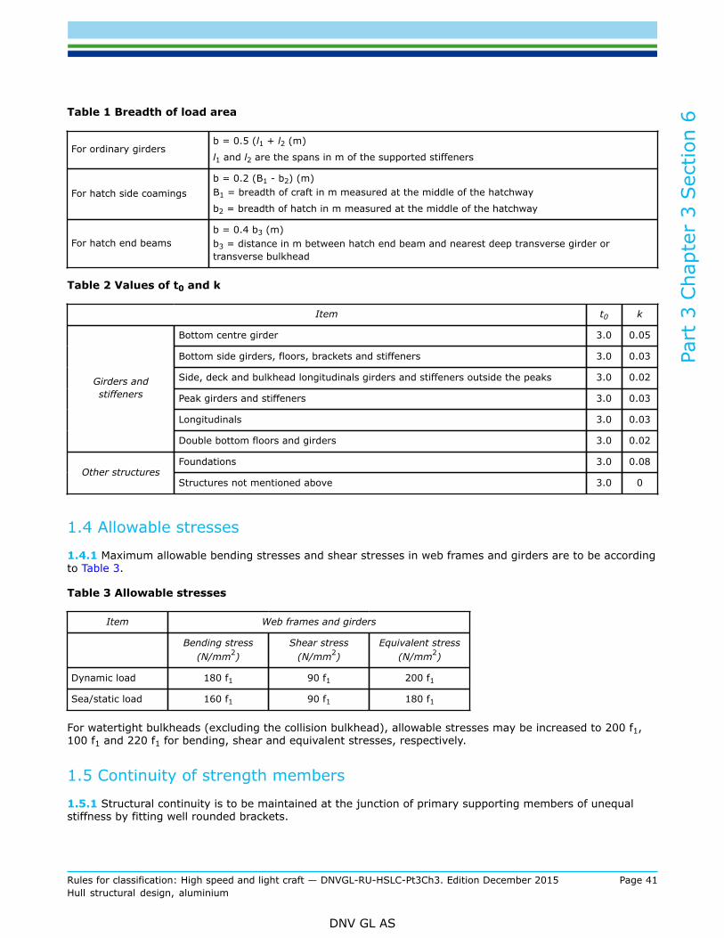
Part
3 C
hapt
er 3
Sec
tion
6
Rules for classification: High speed and light craft — DNVGL-RU-HSLC-Pt3Ch3. Edition December 2015 Page 41Hull structural design, aluminium
DNV GL AS
Table 1 Breadth of load area
For ordinary girdersb = 0.5 (l1 + l2 (m)
l1 and l2 are the spans in m of the supported stiffeners
For hatch side coamingsb = 0.2 (B1 - b2) (m)B1 = breadth of craft in m measured at the middle of the hatchway
b2 = breadth of hatch in m measured at the middle of the hatchway
For hatch end beamsb = 0.4 b3 (m)b3 = distance in m between hatch end beam and nearest deep transverse girder ortransverse bulkhead
Table 2 Values of t0 and k
Item t0 k
Bottom centre girder 3.0 0.05
Bottom side girders, floors, brackets and stiffeners 3.0 0.03
Side, deck and bulkhead longitudinals girders and stiffeners outside the peaks 3.0 0.02
Peak girders and stiffeners 3.0 0.03
Longitudinals 3.0 0.03
Girders andstiffeners
Double bottom floors and girders 3.0 0.02
Foundations 3.0 0.08Other structures
Structures not mentioned above 3.0 0
1.4 Allowable stresses
1.4.1 Maximum allowable bending stresses and shear stresses in web frames and girders are to be accordingto Table 3.
Table 3 Allowable stresses
Item Web frames and girders
Bending stress(N/mm2)
Shear stress(N/mm2)
Equivalent stress(N/mm2)
Dynamic load 180 f1 90 f1 200 f1
Sea/static load 160 f1 90 f1 180 f1
For watertight bulkheads (excluding the collision bulkhead), allowable stresses may be increased to 200 f1,100 f1 and 220 f1 for bending, shear and equivalent stresses, respectively.
1.5 Continuity of strength members
1.5.1 Structural continuity is to be maintained at the junction of primary supporting members of unequalstiffness by fitting well rounded brackets.

Part
3 C
hapt
er 3
Sec
tion
6
Rules for classification: High speed and light craft — DNVGL-RU-HSLC-Pt3Ch3. Edition December 2015 Page 42Hull structural design, aluminium
DNV GL AS
Brackets are to extend to the nearest stiffener, or local plating reinforcement is to be provided at the toe ofthe bracket.
1.5.2 Where practicable, deck pillars are to be located in line with pillars above or below.
2 Web frames and primary structure elements
2.1 General
2.1.1 The requirements for section modulus and web area given in [2.4] are applicable to simple girderssupporting stiffeners or other girders exposed to linearly distributed lateral pressure. It is assumed thatthe girder satisfies the basic assumptions of simple beam theory and that the supported members areapproximately evenly spaced and similarly supported at both ends. Other loads will have to be speciallyconsidered.
2.1.2 When boundary conditions for individual girders are not predictable due to dependence of adjacentstructures, direct calculations according to the procedures given in Sec.9 [4] will be required.
2.1.3 The section modulus and web area of the girder are to be taken in accordance with requirements asgiven in the following. Structural modelling in connection with direct stress analysis is to be based on thesame requirements when applicable. Note that such structural modelling will not reflect the stress distributionat local flange cutouts or at supports with variable stiffness over the flange width. The local effective flangewhich may be applied in stress analysis is indicated for construction details in various Classification Notes on«strength analysis of hull structures)».
2.2 Effective flange
2.2.1 The effective plate flange area is defined as the cross-sectional area of plating within the effectiveflange width. Continuous stiffeners may be included with 50% of their cross-sectional area. The effectiveflange width be is determined by the following formula:
be = C · b (m)
C = as given in Table 4 for various numbers of evenly spaced point loads (r) on the span.
If the above method of calculation is used for strength members that support corrugations perpendicular tothe span of the strength member, C is to be reduced by 90%.
Table 4 Values of C
a/b 0 1 2 3 4 5 6 ≥ 7
C (r ≥ 6) 0.00 0.38 0.67 0.84 0.93 0.97 0.99 1.00
C (r = 5) 0.00 0.33 0.58 0.73 0.84 0.89 0.92 0.93
C (r = 4) 0.00 0.27 0.49 0.63 0.74 0.81 0.85 0.87
C (r ≤ 3) 0.00 0.22 0.40 0.52 0.65 0.73 0.78 0.80
a = distance between points of zero bending moments= S for simply supported girders= 0.6 S for girders fixed at both ends.

Part
3 C
hapt
er 3
Sec
tion
6
Rules for classification: High speed and light craft — DNVGL-RU-HSLC-Pt3Ch3. Edition December 2015 Page 43Hull structural design, aluminium
DNV GL AS
2.2.2 The effective plate area is not to be less than the effective area of the free flange within the followingregions:
— ordinary girders: total span— continuous hatch side coamings and hatch end beams: length and breadth of the hatch, respectively, and
an additional length of 1 m at each end of the hatch corners.
2.3 Effective web
2.3.1 Holes in girders will generally be accepted, provided the shear stress level is acceptable and thebuckling strength is sufficient. Holes are to be kept well clear of end of brackets and locations where shearstresses are high.
2.4 Strength requirements
2.4.1 The section modulus for girders subjected to lateral pressure is not to be less than:
σ = 160 f1 (maximum)m = bending moment factor, m-values in accordance with [2.4.3] may be applied.
2.4.2 The effective web area of girders subjected to lateral pressure is not to be less than:
ks = shear force factor.
= ks-values in accordance with [2.4.3] may be applieda = number of stiffeners between considered section and nearest supportr = average point load in kN from stiffeners between considered section and nearest supportτ = 90 f1 (maximum).
The a-values shall in no case be taken greater than (n + 1)/4.
n = number of supported stiffeners on the girder span. The web area at the middle of the span is not to beless than 0.5 AW.
2.4.3 The m- and ks-values referred to in [2.4.1] and [2.4.2] may be calculated according to general beamtheory. In Table 5 m- and ks-values are given for some defined load and boundary conditions. Note that thegreatest m-value is to be applied to simple girders. For girders where brackets are fitted or the flange areahas been partly increased due to large bending moment, a smaller m-value may be accepted outside thestrengthened region.

Part
3 C
hapt
er 3
Sec
tion
6
Rules for classification: High speed and light craft — DNVGL-RU-HSLC-Pt3Ch3. Edition December 2015 Page 44Hull structural design, aluminium
DNV GL AS
Table 5 Values of m and ks
Load and boundary conditions Bending moment and shear force factors
Positions
1Support
2Field
3Support
1m1
ks1
2m2
—
3m3
ks3
850.50
4285
0.50
0.38 701.250.63
0.50 125 0.50
650.30
431000.70
0.20 601350.80
0.33 130 0.67
2.4.4 The m- and ks-values referred to in [2.4.1] and [2.4.2] are normally to be as given in Table 6 for thevarious structural items.

Part
3 C
hapt
er 3
Sec
tion
6
Rules for classification: High speed and light craft — DNVGL-RU-HSLC-Pt3Ch3. Edition December 2015 Page 45Hull structural design, aluminium
DNV GL AS
Table 6 Values of m and ks for various structural items
Item m ks
Web frames 100 0.63
Floors 100 0.63Bottom:
Longitudinal girders 100 0.63
Longitudinal girders 100 0.54
Web frames, upper end 100 0.54
Web frames, lower end 100 0.72Side:
Deck girders 100 0.63
Horizontal girders 100 0.54
Vertical girders, upper end 100 0.54Bulkhead:
Vertical girders, lower end 100 0.72
2.4.5 The equivalent stress is not to exceed 180 f1 N/mm2.
2.5 Girder tripping brackets
2.5.1 The spacing ST of tripping brackets is normally not to exceed the values given in Table 7 valid forgirders with symmetrical face plates. For others the spacing will be specially considered.Tripping brackets are further to be fitted near the toe of bracket, near rounded corner of girder frames and inline with any cross ties.
2.5.2 The tripping brackets are to be fitted in line with longitudinals or stiffeners, and are to extend thewhole height of the web plate. The arm length of the brackets along the longitudinals or stiffeners, is notto be less than 40% of the depth of the web plate, the depth of the longitudinal or stiffener deducted. Therequirement may be modified for deep transverses.
2.5.3 Tripping brackets on girders are to be stiffened by a flange or stiffener along the free edge if the lengthof the edge exceeds:
0.06 tt (m)
tt = thickness in mm of tripping bracket.
The area of the stiffening is not to be less than:
10 lt (cm2)
lt = length in m of free edge.
The tripping brackets are to have a smooth transition to adjoining longitudinals or stiffeners exposed to largelongitudinal stresses.

Part
3 C
hapt
er 3
Sec
tion
6
Rules for classification: High speed and light craft — DNVGL-RU-HSLC-Pt3Ch3. Edition December 2015 Page 46Hull structural design, aluminium
DNV GL AS
Table 7 Spacing between tripping brackets
Girder type ST (m)
Bottom and deck transverses
Stringers and vertical webs in general
Longitudinal girders in general
0.02 bfmaximum 6
Longitudinal girders in bottom and strength deck for L > 50m within 0.5 L amidships
Stringers and vertical webs in tanks and machinery spaces
Vertical webs supporting single bottom girders and transverses
0.014 bfmaximum 4
If the web of a strength member forms an angle with the perpendicular to the ship’s side of more than 10°, ST is not toexceed 0.007 bf.bf = flange breadth in mmS = distance between transverse girders in m.
2.6 Girder web stiffeners
2.6.1 The web plate of transverse and vertical girders are to be stiffened where:
hw > 75 tw (mm)
tw = web thickness in mm,
with stiffeners of maximum spacing:
s = 60 tw (mm)
within 20% of the span from each end of the girder and where high shear stresses.
Elsewhere stiffeners are required when:
hw > 90 tw (mm)
with stiffeners of maximum spacing:
s = 90 tw (mm)
For girders supporting other girders, the end requirements may have to be applied all over the span.
2.6.2 Stiffeners are to be fitted along free edges of the openings parallel to the vertical and horizontal axis ofthe opening. Stiffeners may be omitted in one direction if the shortest axis is less than 400 mm and in bothdirections if length of both axes is less than 300 mm. Edge reinforcement may be used as an alternative tostiffeners.

Part
3 C
hapt
er 3
Sec
tion
7
Rules for classification: High speed and light craft — DNVGL-RU-HSLC-Pt3Ch3. Edition December 2015 Page 47Hull structural design, aluminium
DNV GL AS
SECTION 7 PILLARS AND PILLAR BULKHEADS
1 General
1.1 Introduction
1.1.1 In this section requirements for pillars and for bulkhead stiffeners substituting pillars are given.
1.2 Definitions
1.2.1 Symbols:
L, B, D, T, CB, see Ch.1.
t = thickness of plating in mms = stiffener spacing in m, measured along platel = length of pillars, cross ties, bulkhead stiffeners etc. between effective supports normal to their axis in
mI = smallest moment of inertia in cm4, including 40 x plate thickness as flange for bulkhead stiffenerA = cross-sectional area in cm2, including 40 x plate thickness for bulkhead stiffenerp = design pressure as given in Ch.1.
2 Pillars
2.1 Arrangement of pillars
2.1.1 Where practicable, deck pillars are to be located in line with pillars above or below.If arrangement with pillars in line is not possible, primary structure elements will have to be reinforced.
2.1.2 Pillars or equivalent supports are to be arranged below deckhouses, windlasses, winches and otherheavy weights.
2.1.3 The engine room casing is to be supported.
2.1.4 Doublers are to be fitted on deck and inner bottom. When pillars are subject to tension loads, mainly intanks, doublers are not allowed, adequate diamond plates with increased thickness to be fitted as inserts ongirder-/beam flanges. Brackets may be used instead of doublers and diamond plates.
2.1.5 Structural reinforcement below pillars will be considered in the individual cases.

Part
3 C
hapt
er 3
Sec
tion
7
Rules for classification: High speed and light craft — DNVGL-RU-HSLC-Pt3Ch3. Edition December 2015 Page 48Hull structural design, aluminium
DNV GL AS
2.2 Cross-section particulars
2.2.1 The radius of gyration of a member is to be taken as:
Ia = moment of inertia as built in cm4 about the axis perpendicular to the expected direction of bucklingAa = cross-sectional area as built in cm2.
If the end conditions are different with respect to the principle axes of the member, the i-value may have tobe checked for both axes.
2.3 Pillar scantlings
2.3.1 The cross-sectional area of members subjected to compressive loads is not to be less than:
η =
minimum 0.3
P = axial load in kN as given for various strength members in [2.3.2] and [2.3.3]. Alternatively, P may beobtained from direct stress analysis. See Sec.9 [4]
l = length of member in mi = radius of gyration in cmk = 0.7 in general
= 0.6 when design loads are primarily dynamic
σc =
=
σE =
σF = minimum upper yield stress of material in N/mm2
E = modulus of elasticity for aluminium = 69 000 N/mm2.
The formula given for σE is based on hinged ends and axial force only.
If, in special cases, it is verified that one end can be regarded as fixed, the value of σE may be multiplied by2.
If it is verified that both ends can be regarded as fixed, the value of σE may be multiplied by 4.

Part
3 C
hapt
er 3
Sec
tion
7
Rules for classification: High speed and light craft — DNVGL-RU-HSLC-Pt3Ch3. Edition December 2015 Page 49Hull structural design, aluminium
DNV GL AS
In case of eccentric force additional end moments or additional lateral pressure, the strength member is tobe reinforced to withstand bending stresses.
2.3.2 The nominal axial force in pillars is normally to be taken as:
P = n · F
n = number of decks above pillar. In case of a large number of decks (n > 3), a reduction in P will beconsidered based upon a special evaluation of load redistribution
F = the force contribution in kN from each deck above and supported by the pillar in question given by:
F = p · AD (kN)
p = design pressure on deck as given in Ch.1 Sec.3AD = deck area in m2 supported by the pillar, normally taken as half the sum of span of girders supported,
multiplied by their loading breadth.
For centre line pillars supporting hatch end beams (see Figure 1 and Figure 2):
AD =
=
b1 = distance from hatch side to craft's side.
2.3.3 The nominal axial force in cross ties and panting beams is normally to be taken as:
P = e · b · p (kN)
e = mean value of spans in m on both sides of the cross tieb = load breadth in mp = the larger of the pressures in kN/m2 on either side of the cross tie (e.g. for a side tank cross tie, the
pressure head on the craft's side may be different from that on the longitudinal bulkhead).
2.4 Pillars in tanks
2.4.1 Pillars made from hollow sections are not allowed inside tanks.
2.4.2 Where the hydrostatic pressure may give tensile stresses in the pillars and cross members, theirsectional area is not to be less than:
A = 0.07 Adk · pt (cm2)
Adk = deck or side area in m2 supported by the pillar or cross memberpt = design pressure, p in kN/m2 giving tensile stress in the pillar.
The formula may be used also tension control of panting beams and cross ties in tanks.
Doubling plates at ends are not allowed.
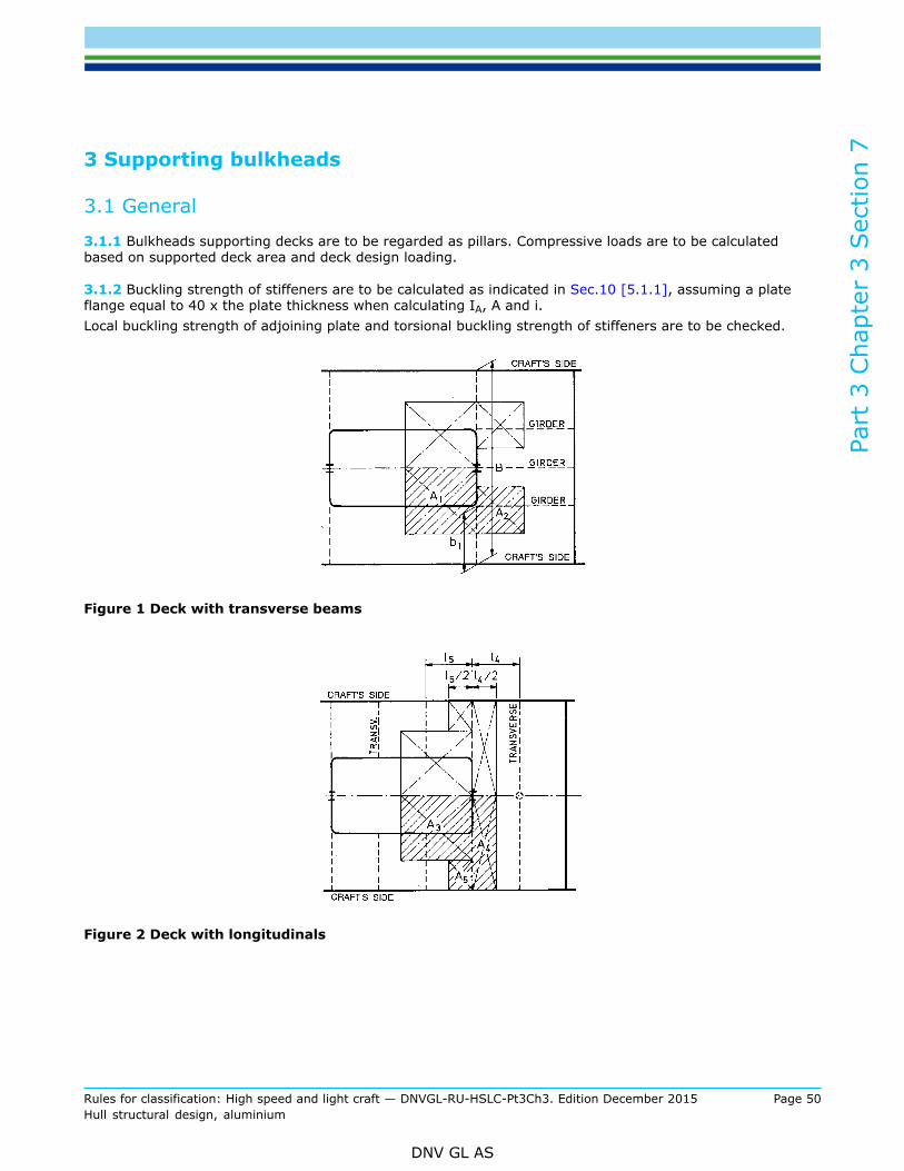
Part
3 C
hapt
er 3
Sec
tion
7
Rules for classification: High speed and light craft — DNVGL-RU-HSLC-Pt3Ch3. Edition December 2015 Page 50Hull structural design, aluminium
DNV GL AS
3 Supporting bulkheads
3.1 General
3.1.1 Bulkheads supporting decks are to be regarded as pillars. Compressive loads are to be calculatedbased on supported deck area and deck design loading.
3.1.2 Buckling strength of stiffeners are to be calculated as indicated in Sec.10 [5.1.1], assuming a plateflange equal to 40 x the plate thickness when calculating IA, A and i.Local buckling strength of adjoining plate and torsional buckling strength of stiffeners are to be checked.
Figure 1 Deck with transverse beams
Figure 2 Deck with longitudinals
Part
3 C
hapt
er 3
Sec
tion
8
Rules for classification: High speed and light craft — DNVGL-RU-HSLC-Pt3Ch3. Edition December 2015 Page 51Hull structural design, aluminium
DNV GL AS
SECTION 8 WELD CONNECTIONS
1 General
1.1 Introduction
1.1.1 In this section requirements for welding of aluminium alloys and various connection details are given.
1.1.2 For general requirements for approval of welding of wrought aluminium alloys, see SHIP Pt.2 Ch.4Sec.5.
1.2 Welding particulars
1.2.1 Welding at ambient air temperature of –5°C or below is only to take place after special agreement.
1.2.2 The welding sequence is to be such that the parts may as far as possible contract freely in order toavoid cracks in already deposited runs of weld. Where a butt meets a seam, the welding of the seam is to beinterrupted well clear of the junction and not be continued until the butt is completed. Welding of butt is tocontinue past the open seam and the weld be chipped out for the seam to be welded straight through.
1.2.3 Welding procedures and welding consumables approved for the type of connection and parent materialin question, are to be used. See “Register of Approved Manufacturers” and “Register of Type ApprovedProducts”.
2 Types of welded joints
2.1 Butt joints
2.1.1 For panels with plates of equal thickness, the joints are normally to be butt welded with preparededges.
2.1.2 For butt welded joints of plates with thickness difference exceeding 2 mm, the thicker plate is normallyto be tapered. The taper is generally not to exceed 1:3.
2.1.3 Welding against permanent or temporary backing is to be specially considered with respect to fatigue,non-destructive examination and any risk of crevice corrosion.

Part
3 C
hapt
er 3
Sec
tion
8
Rules for classification: High speed and light craft — DNVGL-RU-HSLC-Pt3Ch3. Edition December 2015 Page 52Hull structural design, aluminium
DNV GL AS
2.2 Tee or cross joints
2.2.1 The connection of girder and stiffener webs to plate panels, including plating abutting to other platepanels, is normally to be made by fillet welds as indicated in Figure 1.
Figure 1 Tee or cross joints
Where the connection is highly stressed, the edge of the abutting plate may have to be bevelled to give deepor full penetration welding. All welds on outer hull shell boundary as well as centre girder to keel plate shallbe full penetration welding. Where the connection is moderately stressed, intermittent welds may be used.With reference to Figure 2, the various types of intermittent welds are as follows:
— chain weld— staggered weld— scallop weld (closed).
Figure 2 Intermittent welds

Part
3 C
hapt
er 3
Sec
tion
8
Rules for classification: High speed and light craft — DNVGL-RU-HSLC-Pt3Ch3. Edition December 2015 Page 53Hull structural design, aluminium
DNV GL AS
2.2.2 Double continuous welds are required in the following connections irrespective of the stress level:
— oiltight and watertight connections— connections in foundations and supporting structures for machinery— all connections in way of the steering gear arrangement— connections in rudders, except where access difficulties necessitate slot welds— all connections in a region above the propeller extending a radius of minimum 1.5 x the propeller
diameter— connections at supports and ends of stiffeners, pillars, cross ties and girders— centreline girder to keel plate— all structures in ballast tanks and other tanks holding corrosive liquids.

Part
3 C
hapt
er 3
Sec
tion
8
Rules for classification: High speed and light craft — DNVGL-RU-HSLC-Pt3Ch3. Edition December 2015 Page 54Hull structural design, aluminium
DNV GL AS
3 Size of connections
3.1 Fillet welds, general
3.1.1 Unless otherwise stated, the requirements for throat thicknesses are given for double continuous filletwelds. It is assumed that the welding consumables used will give weld deposits with yield strength accordingto SHIP Pt.2 Ch.2 Sec.10 [1.9].
3.1.2 The throat thickness of double continuous fillet weld is not to be less than:
t = 0.42 t0 (mm)
t0 = thickness in mm of thinner of the plates.
The throat thickness is not to be less than 2 mm.
The throat thickness may have to be increased when considered necessary due to a high stress level.
3.1.3 The throat thickness of intermittent welds is to be as required in [3.1.2] for double continuous weldsprovided the welded length is not less than:
— 80% of total length in the slamming area forward of amidships— 60% of total length for connections in tanks and bottom aft of amidships— 45% of total length for connections elsewhere.
t0 = as given in [3.1.2].
Total length means total length of double continuous welds.
3.1.4 Double continuous welds may be required in:
— slamming area— engine room area— adjacent to tanks.
3.2 Fillet welds and penetration welds subject to high tensile stresses
3.2.1 In structural parts where high tensile stresses (> 50 N/mm2) act through an intermediate plate (seeFigure 1) increased fillet welds or penetration welds are to be used. Examples of such structures are:
— transverse bulkhead connection to the double bottom— structural elements in double bottoms below bulkheads— transverse girders to longitudinal bulkheads.
3.2.2 The throat thickness of double continuous weld is not to be less than:
σ = calculated maximum tensile stress in abutting plate in N/mm2
= minimum 50 N/mm2

Part
3 C
hapt
er 3
Sec
tion
8
Rules for classification: High speed and light craft — DNVGL-RU-HSLC-Pt3Ch3. Edition December 2015 Page 55Hull structural design, aluminium
DNV GL AS
r = root face in mmt0 = thickness in mm of thinner of the plates.
3.3 End connections of girders, pillars and cross ties
3.3.1 The weld connection area of bracket to adjoining girders or other structural parts is to be based on thecalculated normal and shear stresses. Double continuous welding is to be used. Where high tensile stressesare expected, welding according to [3.2] is to be applied.
3.3.2 The end connections of simple girders are to satisfy the requirements for section modulus given for thegirder in question.
Where shear stresses in web plates exceed 35 fw N/mm2, double continuous boundary fillet welds are to havethroat thickness not less than:
τ = calculated shear stress in N/mm2
t0 = thickness of abutting plate.fw = material factor for weld deposit
= σfw/240σfw = yield strength in N/mm2 of weld deposit.
3.3.3 End connections of pillars and cross ties are to have a weld area not less than:
A = load area in m2 for pillar or cross tiep = design pressure in kN/m2 as given in Ch.1fw = as given in [3.3.2].
3.4 End connections of stiffeners
3.4.1 Stiffeners may be connected to the web plate of girders in the following ways:
— welded directly to the web plate on one or both sides of the frame— connected by single- or double-sided lugs— with stiffener or bracket welded on top of frame— a combination of the above mentioned connections.
In locations with great shear stresses in the web plate, a double-sided connection or a stiffening of theunconnected web plate edge is normally required. A double-sided connection may be taken into accountwhen calculating the effective web area.
3.4.2 The connection area at supports of stiffeners is normally not to be less than:

Part
3 C
hapt
er 3
Sec
tion
8
Rules for classification: High speed and light craft — DNVGL-RU-HSLC-Pt3Ch3. Edition December 2015 Page 56Hull structural design, aluminium
DNV GL AS
c = factor as given in Table 1k = 0.125 for pressure acting on stiffener side
= 0.1 for pressure acting on opposite sidel = span of stiffener in ms = spacing between stiffeners in mp = design pressure in kN/m2 as given in Ch.1fw = as given in [3.3.2].
Table 1 c-factors
Type of connection(see Figure 3)
Stiffener or bracket on top of stiffener
None Single-sided Double-sided
a 1.00 1.25 1.00
b 0.90 1.15 0.90
c 0.80 1.00 0.80
3.4.3 Various standard types of connections are shown in Figure 3.Other types of connection will be considered in each case.
Figure 3 End connections
3.4.4 Connection lugs are to have a thickness not less than the web plate thickness.
3.4.5 Lower ends of peak frames are to be connected to the floors by a weld area not less than:

Part
3 C
hapt
er 3
Sec
tion
8
Rules for classification: High speed and light craft — DNVGL-RU-HSLC-Pt3Ch3. Edition December 2015 Page 57Hull structural design, aluminium
DNV GL AS
l, s p and fw = as given in [3.4.2].
3.4.6 Bracketed end connections as mentioned in [3.4.7] and [3.4.8] are to have a weld area not less than:
Z = section modulus of stiffener in cm3
h = stiffener height in mmk = 24 for connections between supporting plates in double bottoms and transverse bottom frames or
reversed frames= 25 for connections between the lower end of main frames and brackets= 15 for brackets fitted at lower end of tween deck frames, and for brackets on stiffeners= 10 for brackets on tween deck frames carried through the deck and overlapping the underlying bracket
fw = as given in [3.3.2].
3.4.7 Brackets between transverse deck beams and frames or bulkhead stiffeners are to have a weld areanot less than:
tb = thickness in mm of bracketZ = as defined in [3.4.6].
3.4.8 The weld area of brackets to longitudinals is not to be less than the sectional area of the longitudinal.Brackets are to be connected to bulkhead by a double continuous weld.

Part
3 C
hapt
er 3
Sec
tion
9
Rules for classification: High speed and light craft — DNVGL-RU-HSLC-Pt3Ch3. Edition December 2015 Page 58Hull structural design, aluminium
DNV GL AS
SECTION 9 DIRECT STRENGTH CALCULATIONS
1 General
1.1 Introduction
1.1.1 In the preceding sections the scantlings of the various primary and secondary hull structures (girdersystems, stiffeners and plating) have been given explicitly, based on the design principles outlined inCh.1 Sec.2. In some cases direct strength or stress calculations have been referred to in the text. Thebackground and assumptions for carrying out such calculations in addition to or as a substitute to the specificrequirements are given in this section. Load conditions, allowable stresses and applicable calculation methodsare specified.
1.2 Application
1.2.1 The application of direct stress analysis is governed by:
a) Required as part of rule scantling determination. In such cases where simplified formulations are notable to take into account special stress distributions, boundary conditions or structural arrangementswith sufficient accuracy, direct stress analysis has been required in the rules.
b) As alternative basis for the scantlings. In some cases direct stress calculations may give reducedscantlings, especially when optimisation routines are incorporated.
2 Plating
2.1 General
2.1.1 Normally direct strength analysis of laterally loaded plating is not required as part of rule scantlingestimation.
2.1.2 Buckling control of plating subjected to large in-plane compressive stresses is specified in Sec.4.
2.2 Calculation procedure
2.2.1 Laterally loaded local plate fields may be subject to direct stress analysis applying general 3-dimensional plate theory or finite element calculations. The calculations should take into account theboundary conditions of the plate field as well as membrane stresses developed during deflection of the plate.
2.3 Allowable stresses
2.3.1 When combining the calculated local bending stress with in-plane stresses the equivalent stress σe inthe middle of a local plate field is not to exceed 240 f1 N/mm2. The local bending stress in the same point isin no case to exceed 160 f1 N/mm2.
σx = arithmetic sum of local bending stress and in-plane stresses in the x-directionσy = arithmetic sum of local bending stress and in-plane stresses in the y-directionτ = shear stress in the xy-plane.

Part
3 C
hapt
er 3
Sec
tion
9
Rules for classification: High speed and light craft — DNVGL-RU-HSLC-Pt3Ch3. Edition December 2015 Page 59Hull structural design, aluminium
DNV GL AS
2.3.2 The final thickness is not, however, to be less than the minimum thickness given in Sec.5 for thestructure in question.
3 Stiffeners
3.1 General
3.1.1 Direct strength analysis of stiffeners may be requested in the following cases:
— stiffeners on supports with different deflection characteristics— stiffeners subjected to large bending moments transferred from adjacent structures at supports.
3.1.2 Buckling control of stiffeners subjected to large axial, compressive stresses is specified in Sec.4.
3.2 Calculation procedure
3.2.1 The calculations are to reflect the structural response of the 2- or 3-dimensional structure considered.Calculations based on elastic beam theory may normally be applied, with due attention to:
— boundary conditions— shear area and moment of inertia variations— effective flange— effects of bending, shear and axial deformations— influence of end brackets.
3.3 Loads
3.3.1 The local lateral loads are to be taken as specified in Ch.1 for the structure in question.
3.4 Allowable stresses
3.4.1 The allowable stress level is given in Table 1.
Table 1 Allowable stress levels
Nominal local bending stress σ = 160 f1 N/mm2
Combined local bending stress or girder stress or longitudinal stress σ = 220 f1 N/mm2
Nominal shear stress τ = 90 f1 N/mm2

Part
3 C
hapt
er 3
Sec
tion
9
Rules for classification: High speed and light craft — DNVGL-RU-HSLC-Pt3Ch3. Edition December 2015 Page 60Hull structural design, aluminium
DNV GL AS
4 Primary structure elements
4.1 General
4.1.1 For primary structure elements which are parts of a complex 2- or 3-dimensional structural system,a complete structural analysis may have to be carried out to demonstrate that the stresses are acceptablewhen the structure is loaded as described in [4.3].
4.1.2 Calculations as mentioned in [4.1.1] may be requested to be carried out for:
— bottom structures— side structures— deck structures— bulkhead structures— transverse structures— other structures when deemed necessary by the Society.
4.1.3 In addition to the complex structures indicated above, direct strength calculations may also beperformed on more simple girders in order to optimise scantlings.
4.2 Calculation methods
4.2.1 Calculation methods or computer programs applied are to take into account the effects of bending,shear, axial and torsional deformations.The calculations are to reflect the structural response of the 2- or 3-dimensional structure considered, withdue attention to boundary conditions.For systems consisting of slender girders, calculations based on beam theory (frame work analysis) may beapplied, with due attention to:
— shear area variation— moment of inertia variation— effective flange.
4.2.2 For deep girders, bulkhead panels, etc. where results obtained by applying the beam theory areunreliable, finite element analysis or equivalent methods are to be applied.
4.3 Design load conditions
4.3.1 The calculations are to be based on loads at design level as given in Ch.1. For sea-going conditionsrealistic combinations of external and internal dynamic loads are to be considered.The mass of deck structures may be neglected when less than 5% of the applied loads.

Part
3 C
hapt
er 3
Sec
tion
9
Rules for classification: High speed and light craft — DNVGL-RU-HSLC-Pt3Ch3. Edition December 2015 Page 61Hull structural design, aluminium
DNV GL AS
4.3.2 For transverse web frame beam element analysis, the following combinations of load apply:
— sea pressure on all elements— slamming pressure on bottom.
If twin hull, the following three conditions are to be added:
— slamming pressure on bottom from outside and sea pressure on hull outer side— slamming pressure on bottom from inside and sea pressure on tunnel side and tunnel top— slamming pressure on tunnel top and sea pressure on tunnel side and bottom from inside
For all load cases, deck load pressure from cargo, passengers, etc., is to be added.
4.4 Allowable stresses
4.4.1 The equivalent stress is defined as:
σx = normal stress in x-directionσy = normal stress in y-directionτ = shear stress in the xy-plane.
4.4.2 The longitudinal combined stress taken as the sum of hull girder and longitudinal bottom, side or deckgirder bending stresses, is normally not to exceed 190 f1 N/mm2.
4.4.3 For girders in general, the following stresses are normally acceptable:
Normal stress:
σ = 160 f1 N/mm2.
Mean shear stress:
τ = 90 f1 N/mm2 for girders with one plate flangeτ = 100 f1 N/mm2 for girders with two plate flanges.
Equivalent stress:
σe = 180 f1 N/mm2.

Part
3 C
hapt
er 3
Sec
tion
10
Rules for classification: High speed and light craft — DNVGL-RU-HSLC-Pt3Ch3. Edition December 2015 Page 62Hull structural design, aluminium
DNV GL AS
SECTION 10 BUCKLING CONTROL
1 General
1.1 Definitions
1.1.1 Symbols:
t = thickness in mm of platings = shortest side of plate panel in ml = longest side of plate panel in m
= length in m of stiffener, pillar etc.E = modulus of elasticity of the material
= 0.69 · 105 N/mm2 for aluminiumσel = the ideal elastic (Euler) compressive buckling stress in N/mm2
σf = minimum upper yield stress of material in N/mm2. Usually base material properties are used, butcritical or extensive weld zones may have to be taken into account
τel = the ideal elastic (Euler) shear buckling stress in N/mm2
τf = minimum shear yield stress of material in N/mm2
=
σc = the critical compressive buckling stress in N/mm2
τc = the critical shear stress in N/mm2
τc = calculated actual compressive stress in N/mm2
τa = calculated actual shear stress in N/mm2
η = stability (usage) factor = σa/σc = τa/τcZn = vertical distance in m from the baseline or deckline to the neutral axis of the hull girder, whichever
is relevantZa = vertical distance in m from the baseline or deckline to the point in question below or above the
neutral axis, respectively.

Part
3 C
hapt
er 3
Sec
tion
10
Rules for classification: High speed and light craft — DNVGL-RU-HSLC-Pt3Ch3. Edition December 2015 Page 63Hull structural design, aluminium
DNV GL AS
1.1.2 Relationships:
σc =
=
τc =
=
Guidance note:
When the required σc or τc is known, the necessary σel or τel will from the above expressions of the Johnson-Ostenfeld relationship be
KJ− 0 from Figure 1 or from formula
KJ− 0 =
Figure 1
---e-n-d---of---g-u-i-d-a-n-c-e---n-o-t-e---

Part
3 C
hapt
er 3
Sec
tion
10
Rules for classification: High speed and light craft — DNVGL-RU-HSLC-Pt3Ch3. Edition December 2015 Page 64Hull structural design, aluminium
DNV GL AS
2 Longitudinal buckling load
2.1 Longitudinal stresses
2.1.1 See Ch.1 Sec.4 [1.7].
3 Transverse buckling load
3.1 Transverse stresses
3.1.1 Transverse hull stresses in compression may occur from:
— transverse loads and moments in twin hull craft, see Sec.4 [5]— supports of craft's side structure, see Sec.6.
4 Plating
4.1 Plate panel in uni-axial compression
4.1.1 The ideal elastic buckling stress may be taken as:
For plating with longitudinal stiffeners (in direction of compressive stress):
For plating with transverse stiffeners (perpendicular to compressive stress):
c = 2.50 when stiffeners are hollow profiles with s/l <0.5 and the enclosed area of the hollow profile islarger than 20 s · t
= 1.21 when stiffeners are angles or T-sections= 1.10 when stiffeners are bulb flats= 1.05 when stiffeners are flat bars.
For double bottom panels the c-values may be multiplied by 1.1.

Part
3 C
hapt
er 3
Sec
tion
10
Rules for classification: High speed and light craft — DNVGL-RU-HSLC-Pt3Ch3. Edition December 2015 Page 65Hull structural design, aluminium
DNV GL AS
ψ is the ratio between the smaller and the larger compressive stress assuming linear variation, see Figure 2.
The above correction factors are not valid for negative values of ψ.
The critical buckling stress is found from [1.1.2].
Figure 2 Buckling stress correction factor
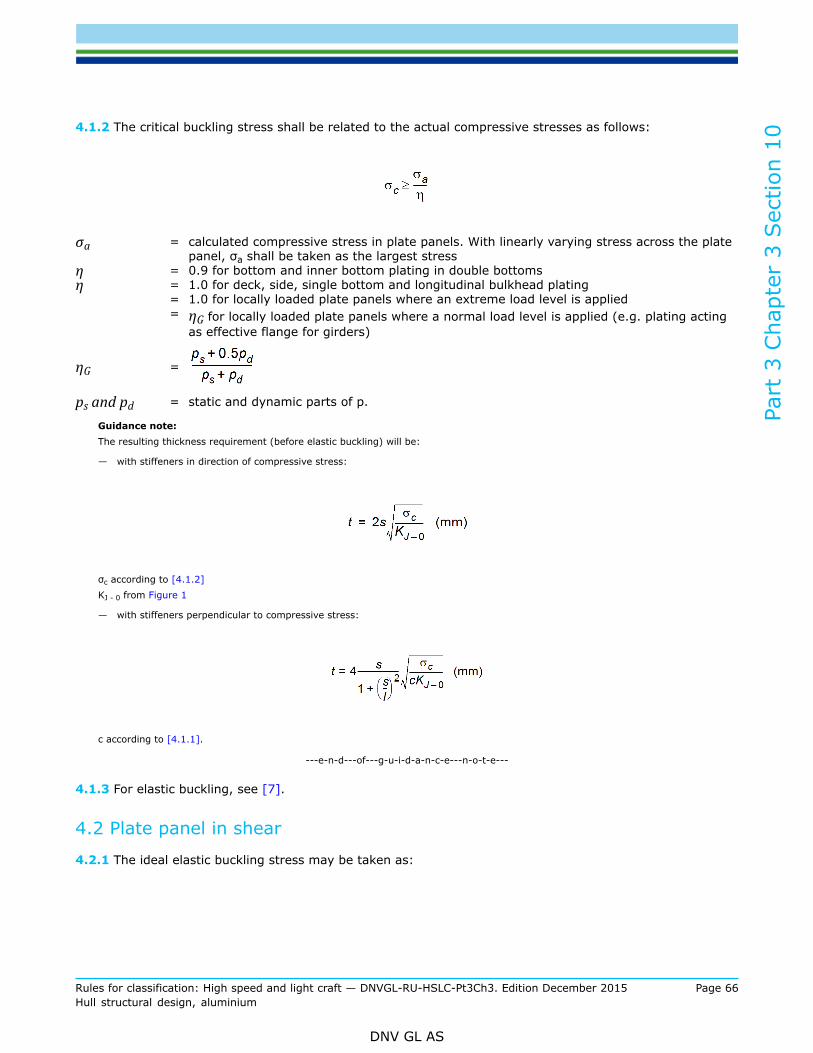
Part
3 C
hapt
er 3
Sec
tion
10
Rules for classification: High speed and light craft — DNVGL-RU-HSLC-Pt3Ch3. Edition December 2015 Page 66Hull structural design, aluminium
DNV GL AS
4.1.2 The critical buckling stress shall be related to the actual compressive stresses as follows:
σa = calculated compressive stress in plate panels. With linearly varying stress across the platepanel, σa shall be taken as the largest stress
η = 0.9 for bottom and inner bottom plating in double bottomsη = 1.0 for deck, side, single bottom and longitudinal bulkhead plating
= 1.0 for locally loaded plate panels where an extreme load level is applied= ηG for locally loaded plate panels where a normal load level is applied (e.g. plating acting
as effective flange for girders)
ηG =
ps and pd = static and dynamic parts of p.
Guidance note:The resulting thickness requirement (before elastic buckling) will be:
— with stiffeners in direction of compressive stress:
σc according to [4.1.2]KJ - 0 from Figure 1
— with stiffeners perpendicular to compressive stress:
c according to [4.1.1].
---e-n-d---of---g-u-i-d-a-n-c-e---n-o-t-e---
4.1.3 For elastic buckling, see [7].
4.2 Plate panel in shear
4.2.1 The ideal elastic buckling stress may be taken as:

Part
3 C
hapt
er 3
Sec
tion
10
Rules for classification: High speed and light craft — DNVGL-RU-HSLC-Pt3Ch3. Edition December 2015 Page 67Hull structural design, aluminium
DNV GL AS
The critical shear buckling stress is found from [1.1.2].
4.2.2 The critical shear stress shall be related to the actual shear stresses as follows:
η = 0.90 for craft's side and longitudinal bulkhead subject to hull girder shear forces= 0.95 ηG for local panels in girder webs when nominal shear stresses are calculated (τa = Q/A)= ηG for local panels in girder webs when shear stresses are determined by finite element calculations or
similarηG = according to [4.1.2].
Guidance note:The resulting thickness requirement will be:
τc according to [4.2.2]
KJ - 0 from Figure 1.
---e-n-d---of---g-u-i-d-a-n-c-e---n-o-t-e---
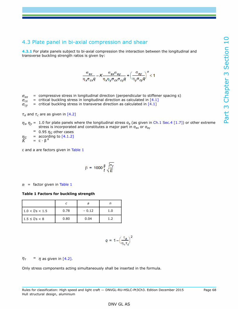
Part
3 C
hapt
er 3
Sec
tion
10
Rules for classification: High speed and light craft — DNVGL-RU-HSLC-Pt3Ch3. Edition December 2015 Page 68Hull structural design, aluminium
DNV GL AS
4.3 Plate panel in bi-axial compression and shear
4.3.1 For plate panels subject to bi-axial compression the interaction between the longitudinal andtransverse buckling strength ratios is given by:
σax = compressive stress in longitudinal direction (perpendicular to stiffener spacing s)σcx = critical buckling stress in longitudinal direction as calculated in [4.1]σcy = critical buckling stress in transverse direction as calculated in [4.1]
τa and τc are as given in [4.2]
ηx, ηy = 1.0 for plate panels where the longitudinal stress σa (as given in Ch.1 Sec.4 [1.7]) or other extremestress is incorporated and constitutes a major part in σax or σay
= 0.95 ηG other casesηG = according to [4.1.2]K = c · β a
c and a are factors given in Table 1
n = factor given in Table 1
Table 1 Factors for buckling strength
c a n
1.0 < l/s < 1.5 0.78 – 0.12 1.0
1.5 ≤ l/s < 8 0.80 0.04 1.2
ητ = η as given in [4.2].
Only stress components acting simultaneously shall be inserted in the formula.

Part
3 C
hapt
er 3
Sec
tion
10
Rules for classification: High speed and light craft — DNVGL-RU-HSLC-Pt3Ch3. Edition December 2015 Page 69Hull structural design, aluminium
DNV GL AS
For plate panels in structures subject to longitudinal stresses, such stresses shall be directly combinedwith local stresses to the extent they are acting simultaneously and for relevant load conditions. Otherwisecombinations based on statistics may be applied.
Guidance note:For shear in combination with:
— uni-axial compression:
may be written:
and with:
— bi-axial compression, approximately:
For bi-axial compression alone q = 1.
---e-n-d---of---g-u-i-d-a-n-c-e---n-o-t-e---
5 Stiffeners in direction of compression
5.1 Lateral buckling mode
5.1.1 The ideal elastic lateral buckling stress may be taken as:
IA = moment of inertia in cm4 about the axis perpendicular to the expected direction of bucklingA = cross-sectional area in cm2.
When calculating IA and A, a plate flange equal to 0.8 times the spacing is included for stiffeners.
The critical buckling stress is found from [1.1.2].

Part
3 C
hapt
er 3
Sec
tion
10
Rules for classification: High speed and light craft — DNVGL-RU-HSLC-Pt3Ch3. Edition December 2015 Page 70Hull structural design, aluminium
DNV GL AS
The formula given for σel is based on hinged ends and axial force only.
Continuous stiffeners supported by equally spaced girders are regarded as having hinged ends whenconsidered for buckling.
In case of eccentric force, additional end moments or additional lateral pressure, the strength member shallbe reinforced to withstand bending stresses.
5.1.2 For longitudinals and other stiffeners in the direction of compressive stresses, the critical bucklingstress calculated in [5.1.1] shall be related to the actual compressive stress as follows:
σa = calculated extreme compressive stress, or ordinary local load stress divided by ηG from [4.1]η = 0.85 for continuous stiffeners.
= 1– ηb, maximum 0.85 for single-span stiffenersηb = (simultaneous bending moment at midspan)/bending moment capacity
Guidance note:The resulting maximum allowable slenderness will be:
KJ-0 from Figure 1.
---e-n-d---of---g-u-i-d-a-n-c-e---n-o-t-e---
5.2 Torsional buckling mode
5.2.1 For longitudinals and other stiffeners in the direction of compressive stresses, the ideal elastic bucklingstress for the torsional mode may in general be calculated from formulae in DNVGL CG0128 Bucklinganalysis.
5.2.2 The critical buckling stress as found from [5.2.1] and [1.1.2] shall not be less than:

Part
3 C
hapt
er 3
Sec
tion
10
Rules for classification: High speed and light craft — DNVGL-RU-HSLC-Pt3Ch3. Edition December 2015 Page 71Hull structural design, aluminium
DNV GL AS
σa = calculated extreme compressive stress, or ordinary local load stress divided by ηG from [4.1]η = 0.85 in general
= 0.8 when the adjacent plating is allowed to buckle in the elastic mode, according to [7].
Guidance note:To avoid torsional buckling the height of flats should not exceed:
tw = thickness of web in mm
KJ - 0 from Figure 1.For flanged profiles, 1 < hw/bf < 3Minimum flange breadth may be taken as:For symmetrical flanges:
For unsymmetrical flanges:
KJ− 0 = according to Figure 1hw = height of web in mm.
---e-n-d---of---g-u-i-d-a-n-c-e---n-o-t-e---
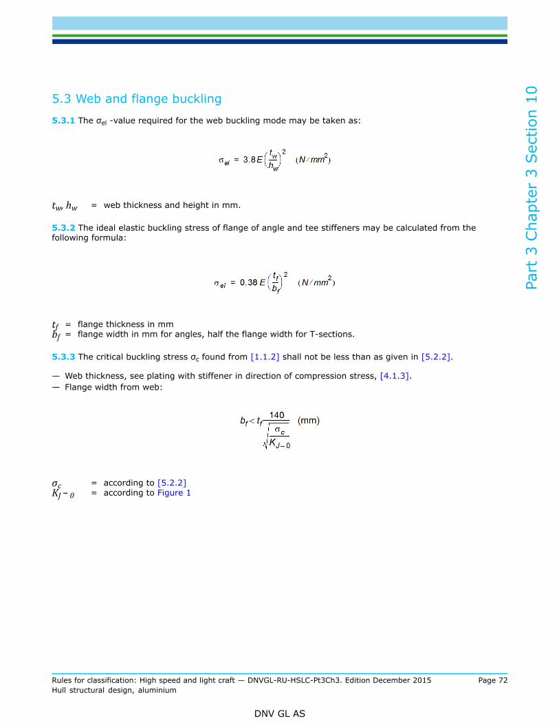
Part
3 C
hapt
er 3
Sec
tion
10
Rules for classification: High speed and light craft — DNVGL-RU-HSLC-Pt3Ch3. Edition December 2015 Page 72Hull structural design, aluminium
DNV GL AS
5.3 Web and flange buckling
5.3.1 The σel -value required for the web buckling mode may be taken as:
tw, hw = web thickness and height in mm.
5.3.2 The ideal elastic buckling stress of flange of angle and tee stiffeners may be calculated from thefollowing formula:
tf = flange thickness in mmbf = flange width in mm for angles, half the flange width for T-sections.
5.3.3 The critical buckling stress σc found from [1.1.2] shall not be less than as given in [5.2.2].
— Web thickness, see plating with stiffener in direction of compression stress, [4.1.3].— Flange width from web:
σc = according to [5.2.2]KJ − 0 = according to Figure 1

Part
3 C
hapt
er 3
Sec
tion
10
Rules for classification: High speed and light craft — DNVGL-RU-HSLC-Pt3Ch3. Edition December 2015 Page 73Hull structural design, aluminium
DNV GL AS
6 Stiffeners perpendicular to direction of compression
6.1 Moment of inertia of stiffeners
6.1.1 For stiffeners supporting plating subject to compressive stresses perpendicular to the stiffener directionthe moment of inertia of the stiffener section (including effective plate flange) shall not be less than:
l = span in m of stiffeners = spacing in m of stiffenerst = plate thickness in mm
σel =
σc =
σa = calculated extreme compressive stress, or ordinary local load stress divided by ηG from [4.1]KJ − 0 = according to Figure 1.
7 Elastic buckling of stiffened panels
7.1 Elastic buckling as a design basis
7.1.1 Elastic buckling may be accepted for plating between stiffeners when:
— plating σel =σf/2 i.e. σel = σc— ησc of stiffener in direction of compression > ησel of plating.
ησc from [5] and [1.1.2]. To be multiplied by ηG for ordinary local load.
ησel from [4] and [1.1.2]— there are no functional requirements limiting the deflections— extreme loads are used in the calculations.
Guidance note:For the torsional buckling mode of flats may be taken
---e-n-d---of---g-u-i-d-a-n-c-e---n-o-t-e---

Part
3 C
hapt
er 3
Sec
tion
10
Rules for classification: High speed and light craft — DNVGL-RU-HSLC-Pt3Ch3. Edition December 2015 Page 74Hull structural design, aluminium
DNV GL AS
7.2 Allowable compression
7.2.1 The allowable compressive force in the panel may be increased from:
PA = 0.1 ηp σel (Ap + As) (kN)
to:
PA = 0.1 ηp σel (Ap + As) +
ηp, ηs = η for plating and stiffener from [4] and [5]. ηs to be multiplied by ηG for ordinary local loadσel, σc = for plating and stiffener, respectively, from [4] and [5]. Ordinary effective flange shall be used
for stiffenersAp, As = area of plating and stiffener in cm2
be/b = fraction of Ap participating in the post-buckling stress increase
=
σu = ultimate average stress of plating
=
7.2.2 For transversely stiffened plating (compressive stress perpendicular to longest side l of plate panel) is
c =
As = 0
resulting in:
PA = 0.1 ηp σu Ap (kN).
7.2.3 σu may be substituted for σel when calculating uniaxial compression and shear in [4.3].

Part
3 C
hapt
er 3
Sec
tion
10
Rules for classification: High speed and light craft — DNVGL-RU-HSLC-Pt3Ch3. Edition December 2015 Page 75Hull structural design, aluminium
DNV GL AS
8 Primary structure elements
8.1 Axial load buckling
8.1.1 For lateral, torsional, web and flange buckling, see [5], Stiffeners in direction of compression.
8.2 Primary structure elements perpendicular to direction of compression
8.2.1 For transverse primary structure elements supporting longitudinals or stiffeners subject to axialcompression stresses, the ideal elastic buckling stress may be taken as:
S = span of girder in ml = distance between girders in ms = spacing of stiffeners in mIa = moment of inertia of stiffener in cm4
Ib = moment of inertia of transverse girder in cm4
t = plate thickness in mmta = equivalent plate thickness of stiffener area in mm
= (stiffener area)/(stiffener spacing)
The critical buckling stress σc is found from [1.1.2].
8.2.2 The critical buckling stress found from [8.2.1] and [1.1.2] shall not be less than:
σa = calculated compressive stressη = 0.75.
8.3 Buckling of effective flange
8.3.1 Plating acting as effective flange for girders which support crossing stiffeners is to have a satisfactorybuckling strength.
8.3.2 Compressive stresses arising in the plating due to local loading of girders shall be less than ηG x thecritical buckling strength, see [8.3.3]. When calculating the compressive stress the section modulus of thegirder may be based on a plate flange breadth equal to the distance between girders (100% effective flange).
ηG: see [4.1].

Part
3 C
hapt
er 3
Sec
tion
10
Rules for classification: High speed and light craft — DNVGL-RU-HSLC-Pt3Ch3. Edition December 2015 Page 76Hull structural design, aluminium
DNV GL AS
8.3.3 The critical buckling strength is given in [4.1.1] and [1.1.2], when l = span of stiffener or distancefrom girder to eventual buckling stiffener parallel to the girder.
8.3.4 Elastic buckling of deck plating may be accepted after special consideration.Reference is made to [7].The additional PA, and the corresponding additional moment capacity, will, however, refer to a girder sectionwith effective width of deck plating = be.
8.4 Shear buckling of web
8.4.1 See [4.2], for constant shear force over l.Guidance note:
For variable shear force over l of panel, a reduced l may be considered in formula.
---e-n-d---of---g-u-i-d-a-n-c-e---n-o-t-e---

DNV GLDriven by our purpose of safeguarding life, property and the environment, DNV GL enablesorganizations to advance the safety and sustainability of their business. We provide classification andtechnical assurance along with software and independent expert advisory services to the maritime,oil and gas, and energy industries. We also provide certification services to customers across a widerange of industries. Operating in more than 100 countries, our 16 000 professionals are dedicated tohelping our customers make the world safer, smarter and greener.
SAFER, SMARTER, GREENER