dnvgl-se-0439 certification of condition monitoring · pdf file2.2.5 re-certification of...
TRANSCRIPT

SERVICE SPECIFICATION
DNVGL-SE-0439 Edition June 2016
Certification of condition monitoring
DNV GL AS
The electronic pdf version of this document found through http://www.dnvgl.com is the officially binding version. The documents are available free of charge in PDF format.
FOREWORD
DNV GL service specifications contain procedural requirements for obtaining and retaining certificates andother conformity statements to the objects, personnel, organisations and/or operations in question.© DNV GL AS June 2016
Any comments may be sent by e-mail to [email protected]
This service document has been prepared based on available knowledge, technology and/or information at the time of issuance of this document. The use of thisdocument by others than DNV GL is at the user's sole risk. DNV GL does not accept any liability or responsibility for loss or damages resulting from any use ofthis document.
C
hang
es –
cur
rent
CHANGES – CURRENTGeneralThis is a new document.
Service specification, DNVGL-SE-0439 – Edition June 2016 Page 3
DNV GL AS
C
onte
nts
ContentsCHANGES – CURRENT .................................................................................................. 3
Sec.1 General ......................................................................................................... 61.1 Introduction ...........................................................................................61.2 DNV GL document system ......................................................................7
1.2.1 Scope...........................................................................................71.2.2 Application....................................................................................71.2.3 Definitions ....................................................................................7
1.3 References .............................................................................................81.3.1 General ........................................................................................8
1.4 Procedural requirements........................................................................91.4.1 Customer - DNV GL interaction ........................................................91.4.2 Certification requirements - quality management ...............................91.4.3 Documentation requirements.........................................................101.4.4 Surveillance requirements.............................................................10
Sec.2 General assessment conditions ................................................................... 112.1 Area of application ...............................................................................11
2.1.1 General ......................................................................................112.1.2 Deviations...................................................................................112.1.3 Validity.......................................................................................12
2.2 Scope of the certification......................................................................122.2.1 Structure of the certification ..........................................................122.2.2 Certification of the condition monitoring system ...............................132.2.3 Certification of the monitoring body................................................152.2.4 Audit of certified monitoring bodies ................................................172.2.5 Re-certification of condition monitoring systems and
monitoring bodies ........................................................................18
Sec.3 General requirements ................................................................................. 193.1 Requirements for wind turbine manufacturers,
component suppliers and turbine operators .........................................193.2 Requirements for the manufacturers of
condition monitoring systems ..............................................................19Sec.4 Requirements for a condition monitoring system........................................ 20
4.1 General.................................................................................................204.2 Main components to be monitored .......................................................214.3 Measured values and sensor technology ..............................................21
4.3.1 General ......................................................................................214.3.2 Measured vibration values.............................................................214.3.3 Operational parameters of the wind turbine .....................................224.3.4 Measured particle parameters........................................................234.3.5 Measured oil cleanliness................................................................23
4.4 Handling of signals...............................................................................234.4.1 General ......................................................................................234.4.2 Signal acquisition.........................................................................244.4.3 Signal processing.........................................................................244.4.4 Signal analysis ............................................................................244.4.5 Speed variations ..........................................................................264.4.6 Averaging ...................................................................................264.4.7 Limiting values ............................................................................264.4.8 Trend analysis .............................................................................27
Service specification, DNVGL-SE-0439 – Edition June 2016 Page 4
DNV GL AS
C
onte
nts
4.5 Data storage.........................................................................................274.6 Alarm functions ....................................................................................274.7 Diagnosis .............................................................................................28
Sec.5 Manuals....................................................................................................... 295.1 Installation manual for the condition monitoring system .....................29
5.1.1 General ......................................................................................295.1.2 Format of the installation manual ...................................................295.1.3 Scope of the installation manual ....................................................29
5.2 Documents for the commissioning of the condition monitoring system................................................................305.2.1 Commissioning manual .................................................................305.2.2 Commissioning record ..................................................................305.2.3 Format of the documents ..............................................................305.2.4 Scope of the commissioning manual ...............................................30
5.3 Operating manual for the condition monitoring system........................315.3.1 Purpose of the operating manual....................................................315.3.2 Format of the operating manual .....................................................315.3.3 Scope of the operating manual ......................................................32
5.4 Maintenance manual for the condition monitoring system ...................325.4.1 General ......................................................................................325.4.2 Purpose of the maintenance manual ...............................................325.4.3 Format of the maintenance manual ................................................325.4.4 Scope of the maintenance manual..................................................33
App. A Example certificate/statement.................................................................... 34
Service specification, DNVGL-SE-0439 – Edition June 2016 Page 5
DNV GL AS

1.1 IntroductionA condition monitoring system (CMS) measures vibration and structure-borne sound at the components of the wind turbine, for example at the components of the drive train, and may gather operational parameters, such as power output, speed, and the oil and bearing temperatures.
The monitoring of other components of the wind turbine, for example rotor blades or tower, is reasonable.
The acquired data is then compared with the established limiting values for the corresponding component. If the CMS determines that a limiting value has been exceeded, an alarm message is automatically sent to the responsible monitoring body (MB). This MB will then carry out an evaluation of the measured values, in order to take the necessary steps.
The quality of the condition monitoring mainly depends on the interpretation and evaluation of the measured values. Certified MB are able to interpret and evaluate the measured values in view of achieving high quality results.
CMS can be realized as “stand alone” systems or can be semi-integrated or fully integrated into the control system. “Semi-integrated” means that the CMS and the control system are using their own central processing unit (CPU), while “fully integrated” means that the CMS uses the CPU of the control system.
This SE is divided into five main sections.
Sec.1 provides general information on CMS for wind turbines and general requirements regarding CMS certification for wind turbines and regarding MB certification.
Sec.2 describes the general assessment conditions, where
— [2.1] contains the area of application,
— [2.2] describes the scope of certification.
Sec.3 contains the general requirements, where
— [3.1] lists the requirements for wind turbine manufacturers, component suppliers and wind turbine operators,
— [3.2] lists the requirements for the manufacturers of CMS.
Sec.4 describes the requirements for a CMS, where
— [4.1] contains the general requirements,
— [4.2] describes the main components to be monitored,
— [4.3] describes the measured values and sensor technology,
— [4.4] contains the handling of signals,
— [4.5] describes the data storage,
— [4.6] lists the alarm functions,
— [4.7] describes the diagnosis procedures.
Sec.5 provides information on the manuals, where
— [5.1] contains the requirements for the installation manual for the CMS,
— [5.2] describes the documents necessary for commissioning of the CMS,
— [5.3] contains the requirements for the operating manual for the CMS,
— [5.4] contains the requirements for the maintenance manual for the CMS.
Service specification, DNVGL-SE-0439 – Edition June 2016 Page 6
DNV GL AS

The DNV GL document system is organized according to a three-level document hierarchy, with these main features:
— principles and procedures related to DNV GL’s certification and verification services are separated from technical requirements and are presented in DNV GL service specifications (SE). Service specifications present the scope and extent of DNV GL’s services
— technical requirements are issued as self-contained DNV GL standards (ST). Standards are issued as neutral technical standards to enable their use by national authorities, as international codes and as company or project specifications without reference to DNV GL’s services
— associated product documents are issued as DNV GL recommended practices (RP). Recommended practices provide DNV GL’s interpretation of safe engineering practice
Guidance note:The latest revision of all DNV GL documents can be found in the list of publications on the DNV GL website www.dnvgl.com.
---e-n-d---of---g-u-i-d-a-n-c-e---n-o-t-e---
1.2.1 ScopeThis service specification (SE) describes the requirements for the certification of CMS for wind turbines and of MB. It establishes a basis for the development and installation of CMS in wind turbines and also establishes rules for the application of the measured values, e.g. for their evaluation, interpretation and storage, as well as procedures to be carried out when the stipulated limiting values are exceeded. It specifies DNV GL’s services for certification of CMS for wind turbines and for certification of MB.
Furthermore it provides a common communication platform for describing the scope and extent of activities performed for certification of CMS for wind turbines.
1.2.2 ApplicationThis service specification applies to CMS certification for wind turbines and related verification tasks.
1.2.3 Definitions1.2.3.1 Terminology and definitions
Table 1-1 Definitions of verbal forms
Verbal forms Definition
shall verbal form used to indicate requirements strictly to be followed in order to conform to the document
should verbal form used to indicate that among several possibilities one is recommended as particularly suitable, without mentioning or excluding others, or that a certain course of action is preferred but not necessarily required
may verbal form used to indicate a course of action permissible within the limits of the document
Table 1-2 Definitions of terms
Term Definition
certification refers to third-party issue of a statement, based on a decision following review, that fulfilment of specified requirements has been demonstrated related to products, processes or systems (ISO 17000)
customer DNV GL’s contractual partner (applicant)
monitoring body a company/institution that provides services to monitor the condition of a wind turbine with a CMS
recommendation non-mandatory advice
verification refers to the confirmation, through the provision of objective evidence, that specified requirements have been fulfilled (ISO 9000)
wind turbine system which converts kinetic wind energy into electrical energy Whenever, in this service specification the term is used to describe the wind turbine in general, it describes the rotor-nacelle-assembly including the support structure, as this is the power generating unit.
Service specification, DNVGL-SE-0439 – Edition June 2016 Page 7
DNV GL AS

Abbreviations and symbols used in this service specification.
1.3 References
1.3.1 GeneralThis document makes reference to relevant international documents and DNV GL documents. Unless otherwise specified in the certification agreement or in this service specification, the latest valid revision of each referenced document applies.
Table 1-3 Abbreviations
Abbreviation In full
CMS condition monitoring system
CPU central processing unit
IT information technology
MB monitoring body
QM quality management
SCADA supervisory control and data acquisition
SMS short message service
UPS uninterrupted power supply
Table 1-4 DNV GL documents
Reference TitleDNVGL-SE-0073 Project certification of wind farms according to IEC 61400-22DNVGL-SE-0074 Type and component certification of wind turbines according to IEC 61400-22DNVGL-SE-0190 Project certification of wind power plantsDNVGL-SE-0441 Type and component certification of wind turbinesGL-IV-1 Rules and Guidelines – IV Industrial Services – Part 1: Guideline for the Certification of Wind TurbinesGL-IV-2 Rules and Guidelines – IV Industrial Services – Part 2: Guideline for the Certification of Offshore
Wind TurbinesGL-IV-4 Rules and Guidelines – IV Industrial Services – Part 4: Guideline for the Certification of Condition
Monitoring Systems for Wind Turbines
Table 1-5 IEC documents
Reference TitleIEC 61400-1 Wind Turbines – Part 1: Design requirementsIEC 61400-3 Wind Turbines – Part 3: Design requirements for offshore wind turbinesIEC 61400-22 Wind Turbines – Part 22: Conformity Testing and CertificationIEC 61400-25 Wind Turbines – Part 25: Communications for monitoring and control of wind power plants
Table 1-6 ISO documents
Reference TitleISO 4406 Hydraulic fluid power – Fluids – Method for coding the level of contamination by solid particlesISO 5348 Mechanical vibration and shock – Mechanical mounting of acceleratorsISO 9000 Quality management systems - Fundamentals and vocabularyISO 9001 Quality management systems – Requirements ISO 10816-1 Evaluation of machine vibrations by measurement on non-rotating parts – General guidelinesISO 10816-2 Industrial machines with nominal power above 15 kW and nominal speeds between 120 r/min and
15 000 r/min when measured in situISO 13373-1 Condition monitoring and diagnostics of machines – Vibration condition monitoring – General
procedures
Service specification, DNVGL-SE-0439 – Edition June 2016 Page 8
DNV GL AS

1.4 Procedural requirements
1.4.1 Customer - DNV GL interactionThe CMS certification for wind turbines provides the customer a third party verification and conformity of his CMS wind farm project considering specific needs.
This document has a dual objective. It serves as a publicly available description of DNV GL’s certification services for CMS and it should be referred to as a contractual document in the certification agreement between the customer and DNV GL. The document specifies the obligations of the customer when his CMS is to become certified, as well as DNV GL’s service obligations to the customer.
1.4.2 Certification requirements - quality managementThe customer shall provide evidence of a consistent quality management system covering all aspects of the CMS and/or the MB. In particular the customer shall show quality relevant procedures to DNV GL for his procedures and his suppliers. When a valid certificate for ISO 9001 of an accredited certification body is in place, the certification body may reduce this assessment to a plausibility check.
In general test reports delivered shall be prepared by accredited testing laboratories and meet the requirements of ISO IEC 17025 and relevant standards. For non-accredited test laboratories, DNV GL shall verify that the testing is carried out according IEC/ISO 17025, as applicable.
DNV GL shall be notified without request prior to the introduction of any alterations to the QM system or to production processes which can be expected to have a significant effect on the quality of the CMS and/or MB. DNV GL reserves the right to check these issues (extraordinary inspection) and to review the approval of the QM system.
Insofar as the certification of the QM system of a certification body was recognized by DNV GL, the manufacturer is under an obligation to inform DNV GL without delay about the loss of the certificate’s validity.
ISO/IEC 17000 Conformity assessment - Vocabulary and general principlesISO/IEC 17020 Conformity assessment - Requirements for the operation of various types of bodies performing
inspectionISO/IEC 17025 General requirements for the competence of calibration and testing laboratoriesISO/IEC 17065 Conformity assessment - Requirements for bodies certifying products, processes and servicesISO 17359 Condition monitoring and diagnostics of machines – General guidelines
Table 1-7 Other documents
Reference TitleDIN 31051 Fundamentals of maintenanceVDI 3832 Measurement of structure-borne sound of rolling element bearings in machines and plants for
evaluation of state condition.VDI 3834-1 Measurement and evaluation of the mechanical vibration of wind energy turbines and their
components – Onshore wind energy turbines with gearsVDI 3834-2 Measurement and evaluation of the mechanical vibration of wind energy turbines and their
components – Onshore wind energy turbines with gearless drive (in preparation)VDI 3839-1 Instructions on measuring an interpreting the vibration of machines – General principles.VDI 3839-2 Vibration patterns for excitation arising from unbalance, incorrect assembly, bearing faults and
damage to rotating components.VDI 3839-5 Typical vibration patterns with electrical machines.
Table 1-8 Other references
Reference TitleAllianz Zentrum für Technik
Anforderungen an Condition Monitoring Systeme für Windenergieanlagen; Report No.: 03.01.068, 27 March 2003
Table 1-6 ISO documents (Continued)
Reference Title
Service specification, DNVGL-SE-0439 – Edition June 2016 Page 9
DNV GL AS

The documentation submitted for the certification process shall be complete and self-explanatory. The content shall meet the requirements of the applied standards. All relevant documentation shall be subject oriented and in a logical sequence to facilitate cross checking between documents. Each document shall be named explicitly by e.g. title, report no., page no., date and a revision description table. Furthermore the documents should be signed officially at least by the author and/or the approver to identify responsibilities. Alternatively the documentation submitted shall bear unambiguous evidence of having been subject to designer’s and/or owner’s own quality approval system.
The documentation, including standards and codes as well as other requirements and specifications, shall be prepared in the English language, unless otherwise agreed in writing between DNV GL and the customer.
Drawings, circuit diagrams and flow charts shall be elaborated in compliance with the national and/or international standards and guidelines.
All documentation for verification shall be forwarded to DNV GL in electronic form, preferably as pdf-files. Other forms of documentation such as print-outs can be an alternative, if agreed.
1.4.4 Surveillance requirementsThe customer, or other entity having legal responsibility for the premises where DNV GL personnel will work, shall inform DNV GL of any safety and health hazards related to the work and/or any safety measures required for the work, prior to starting the work, or if such information is not available at that time, during the performance of the work.
Whenever DNV GL undertakes to work on site, the customer shall provide all adequate safety measures to ensure a working environment that is safe and in accordance with all relevant legislation.
If at any time during the execution of work on site a DNV GL employee judges that the work situation is unsafe then work shall be suspended until such situation has been made safe.
Service specification, DNVGL-SE-0439 – Edition June 2016 Page 10
DNV GL AS
2.1 Area of application
2.1.1 GeneralThis service specification applies for the design, assessment and certification of CMS for wind turbines, as well as for the assessment and certification of the MB.
In addition and independently of the components listed in [4.2], systems for the monitoring of other turbine components may also be certified according to this service specification. These include e.g. systems for monitoring and detecting the condition of rotor blades, or for measuring and assessing the oil quality. In such cases, this service specification shall be applied as and where appropriate.
For the certification of a CMS, its overall concept will be evaluated. The scope of the certification includes all the components of the system, which means that its safety, as well as the design, engineering, availability, type and quality will be assessed and evaluated.
The service specification applies for CMS to be retrofitted in wind turbines that are already operational as well as for systems integrated into the hardware and/or software of turbines and their components.
The certification of the MB includes the assessment and evaluation of the technological and operational prerequisites and the implementation of the points described in this service specification.
If the results of trials/tests are to be taken into account during the certification, the trials or tests shall be carried out under the supervision of DNV GL or in an accredited test laboratory.
The conditions for recognition of these trials/tests shall be agreed upon beforehand with DNV GL.
Each trial/test to be recognized within the scope of the certification shall be concluded with a detailed report. This report shall form part of the documents to be submitted for the certification. In the report, the following information shall be provided as a minimum:
— purpose of the trial/test— reason for conducting the trial/test— expected results— constraints of the trial/test— description of the trial/test— presentation of the results of the trial/test— evaluation and analysis of the results of the trial/test— presentation of compliance with the requirements of this service specification— conclusions drawn.
2.1.2 DeviationsNon-fulfilment of parts of this service specification is only allowed when authorized by DNV GL.
In case of any deviations from this service specification, appropriate documents shall be submitted to DNV GL to explain the reasons for the desired deviations. Furthermore, it shall be shown conclusively and in detail how the requirements of this service specification can be met in spite of the deviations. DNV GL will then assess the documents and decide in each individual case whether the deviation is admissible for the purposes of the service specification.
In individual cases, the locally valid or country-specific regulations and requirements can be taken into account for the certification.
This service specification shall be observed as the minimum requirement, even if national or regional laws and regulations establish lower requirements.
In the case of details for which this service specification cannot be used, DNV GL reserves the right to proceed according to the intention of the service specification.
If assessments performed by other bodies are to be recognized for the certification by DNV GL, documents
Service specification, DNVGL-SE-0439 – Edition June 2016 Page 11
DNV GL AS

will assess these documents and decide in each individual case to what extent these documents can be recognized.
2.1.3 ValidityThe assessments and inspections indicated in the following are required in order to obtain a certificate.
Only one type certificate will be issued for each CMS type. If modifications are carried out at components of the CMS type which were part of the certification or if any other kind of modifications affect and change the operating mode of the system, these shall be deemed reasons justifying a re-certification.
The validity of the type certificate for a CMS type is two years, after which a re-certification must be carried out; see [2.2.5].
The conformity statement for the MB is only valid for the corresponding installations which were assessed. If the monitoring procedures or other procedures are altered, DNV GL shall be informed in writing about the modifications. DNV GL will then prepare an assessment or initiate a re-certification of the MB.
After no more than 2.5 years, an audit will take place, and after 5 years a re-certification of the MB will be performed; see [2.2.5].
2.2 Scope of the certification
2.2.1 Structure of the certificationThe certification is divided into the two areas represented in Figure 2-1. On one hand, the type of the CMS is certified, and on the other hand it is also possible to certify the MB.
CMS will be granted a type certificate if their documentation could be successfully assessed, if their development and production comply with the requirements of ISO 9001 (see [1.4.2]), and if their operating mode was examined in a system test.
The monitoring bodies are granted a conformity statement if the required documentation was successfully assessed, if they have implemented a quality management system in accordance with ISO 9001 (see [1.4.2]), and if their procedures were assessed in a practical test.
Service specification, DNVGL-SE-0439 – Edition June 2016 Page 12
DNV GL AS
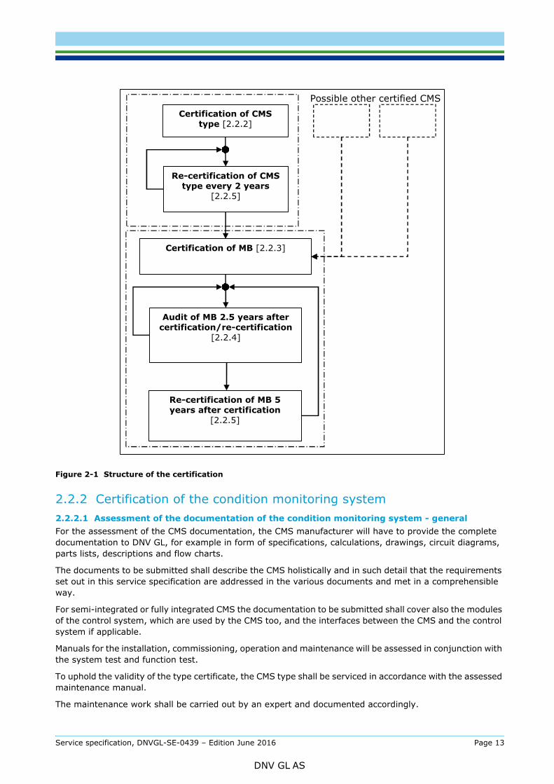
Figure 2-1 Structure of the certification
2.2.2 Certification of the condition monitoring system2.2.2.1 Assessment of the documentation of the condition monitoring system - generalFor the assessment of the CMS documentation, the CMS manufacturer will have to provide the complete documentation to DNV GL, for example in form of specifications, calculations, drawings, circuit diagrams, parts lists, descriptions and flow charts.
The documents to be submitted shall describe the CMS holistically and in such detail that the requirements set out in this service specification are addressed in the various documents and met in a comprehensible way.
For semi-integrated or fully integrated CMS the documentation to be submitted shall cover also the modules of the control system, which are used by the CMS too, and the interfaces between the CMS and the control system if applicable.
Manuals for the installation, commissioning, operation and maintenance will be assessed in conjunction with the system test and function test.
To uphold the validity of the type certificate, the CMS type shall be serviced in accordance with the assessed maintenance manual.
The maintenance work shall be carried out by an expert and documented accordingly.
Possible other certified CMS
Certification of MB [2.2.3]
Certification of CMS type [2.2.2]
Re-certification of CMS type every 2 years
[2.2.5]
Audit of MB 2.5 years after certification/re-certification
[2.2.4]
Re-certification of MB 5 years after certification
[2.2.5]
Service specification, DNVGL-SE-0439 – Edition June 2016 Page 13
DNV GL AS

approved by DNV GL before they are implemented.
2.2.2.2 Assessment of the documentation of the condition monitoring system - documents to be submitted
1) General description of the CMS type, taking into account [4.1] and [4.2]
2) Detailed description of the function mode of the CMS type, including the signal flow chart. Here thefulfilment and implementation of the requirements set out in [4.3] and [4.4] shall be observed andshown accordingly. For each component of the turbine monitored by the CMS, the measurement devicesand the monitoring method(s) shall be described, together with all the constraints.
3) Detailed description of the function mode of the modules of the control system, which are usedcommonly by the control system and the CMS, for semi-integrated or fully integrated CMS.
4) Detailed description of the interfaces between the CMS and the control system for semi-integrated CMS.
5) Description of the software, with details on the setting of limiting values (see [4.4.7]), on the alarmfunctions (see [4.6]) and diagnosis (see [4.7]), and on the data-storage concept (see [4.5]) for the CMStype.
6) Description of the hardware of the CMS type; [4.1] shall also be observed
7) Description of the way in which average values are obtained, which kind of average values are used,and what steps are taken to prevent significant data from being lost for interpretation.
8) Description of how the limiting values are monitored in wind turbines with variable speed.
9) Description of the measures taken for protection against electromagnetic interference caused by thewind turbine or as a result of power failures.
10)Description of how it is ensured that measured data of the CMS are not lost in the event of a power (e.g.through use of an UPS).
11)Description of the automatic restart procedure after a power failure.
12)Manuals: installation manual, commissioning manual, operating manual, maintenance manual withmaintenance plans (Sec.5) of the CMS.
13)Documentary evidence of fulfilment of the requirements according to ISO 9001.
If the documents to be submitted include confidential information which is, however, needed by DNV GL for the certification, special documents that are not included in the set delivered to the turbine operator, such as those specified in 10), may be prepared and submitted to DNV GL separately.
2.2.2.3 Assessment of the documentation of the condition monitoring system - scope of assessmentThe documentation submitted will be assessed in respect of its conformity with this guideline as well as its completeness and plausibility.
2.2.2.4 System testIn system tests, the function mode of the CMS type according to the documentation submitted shall be demonstrated on the basis of real wind turbine data. A data link to a wind turbine equipped with the CMS type to be certified is required for this purpose.
2.2.2.5 Function test - generalAfter concluding the assessment according to [2.2.2.1] and [2.2.2.3], a practical inspection (function test) shall be carried out in the presence of an expert of DNV GL on one of the first CMS of this type installed and in operation at a wind turbine.
The function test of the CMS type can only be carried out at a certified wind turbine whose design assessment was issued or recognized by DNV GL (e.g. issuance by an accredited body) and is still valid.
The objective of the function test is to assess the interaction of the CMS and the turbine as well as the functionality and conformity of the CMS according to the documents submitted; see also [2.2.2.7].
Furthermore, [5.2] shall be observed.
Service specification, DNVGL-SE-0439 – Edition June 2016 Page 14
DNV GL AS
Apart from the information mentioned in [2.2.2.2] the following documentation of the wind turbine will be required in order to prepare the function test of the CMS type:
1) General description or specifications of the wind turbine, including the details according to [3.1].2) Description of the safety system and control system of the wind turbine.3) Circuit diagram and installation description of the CMS type installed in the wind turbine, showing the
position of the sensors and communication appliances between the different parts of the CMS type. Theinstallation records and commissioning records on the CMS for this wind turbine that were completedaccording to Sec.5 also belong here.
4) Data of the turbine needed for calculating the limiting values (e.g. kinematical data).5) Calibration reports or records for the CMS sensors installed in the turbine.6) Furthermore, the implementation of the requirements specified in [4.3] shall be described in detail by
way of example for the turbine at which the function test is performed.
The documents set out in c) shall describe the installation of the CMS type with adequate clarity. They shall show which signals are sensed at what point and how they are transferred to the computing unit of the CMS type.
2.2.2.7 Function test - scope of the assessmentDuring the function test, all the functions of the CMS type resulting from its operational mode have to be assessed. This includes the following assessments and actions, refer also to [5.2]:
— programming of the CMS type (e.g. input of limiting values)— function of sensors— function of the CMS type according to the assessed documentation— triggering of alarm messages as well as testing of the internal component monitoring of the CMS type
(e.g. disconnection of a sensor during operation)— verification of the plausibility of the measured values of the CMS type, including the determination of
speed and output — behaviour in case of power failure— no impact on the control and safety system of the wind turbine, insofar as this influences the certification
of the wind turbine. At this point, the safety-relevant tests for the wind turbine have to be carried out according to GL-IV-1, GL-IV-2 Section1.2.3.7, para 4.
Additionally, the following points will be assessed:
— whether all the components to be monitored according to this service specification are equipped with the corresponding sensors
— whether the sensors are located at suitable positions— whether the sensors are protected against misuse— the installation and interconnection of the sensors and the computing units of the CMS type— the power supply of the CMS type— whether the components used correspond to the components described in the assessed documents
according to [2.2.2.2] and [2.2.2.6].
2.2.3 Certification of the monitoring body2.2.3.1 GeneralDuring the assessment of the MB, it shall be shown how the monitoring of the wind turbine is performed using one CMS type.
A job specification shall be drawn up for the persons (experts) responsible for the monitoring and for the later interpretation of the measured data.
The certification of a MB can only be carried out with at least one CMS type certified by DNV GL.
Service specification, DNVGL-SE-0439 – Edition June 2016 Page 15
DNV GL AS

measured values are repeatedly found to be implausible, the MB shall inform the operator or the department/company contractually stipulated as being responsible.
2.2.3.2 Requirements for the monitoring bodyThe CMS requires continuous and qualified technical support, in order to ensure a rapid response to alarm messages.
Steps shall be taken to ensure continuous support (24 hours a day, 7 days a week) for the wind turbines being monitored by the CMS. For this purpose, the corresponding equipment and qualified personnel shall be kept ready.
In this connection, support does not mean that the MB must actually be manned 24 hours a day and 7 days a week. For example, it is sufficient if the corresponding staff member of the MB is informed immediately about all incoming messages from the CMS and can “log in” to the corresponding CMS whenever necessary. In such case, the relevant documented procedures must be prepared.
If applicable, a prioritization of alarms may lead to a reduction in the number of alarm messages to be accepted personally.
Another task of the MB is also e.g. to adapt the limiting values after maintenance and repair work.
The MB shall be familiar with the wind turbine to be monitored, and shall have detailed documentation about the components to be monitored; see [3.1].
For the interpretation of the measured data and the adaptation of the limiting values, the experience gained about the actual lifetime of the components shall be taken into account.
All the settings carried out at the CMS type of a wind turbine shall be documented in a comprehensible way. Similarly, any limiting value transgressions measured after the turbine-specific system adaptation shall be documented in a comprehensible way and archived for the lifetime of the turbine.
A procedure and the responsibilities shall be established in a written manner in order to determine the response by the MB in case of the receipt of an alarm message, for example when limiting values are exceeded.
A general written description shall be formulated to describe the procedures for the monitoring of the wind turbine by CMS.
The interpretation of the received alarm message requires sufficient technical knowledge as well as knowledge of the turbine. For the interpretation of the measured data, trained experts shall be consulted.
The technical knowledge is assessed by perusal of the training documents and certificates on courses and seminars that have been taken in relation to the job specification (see [2.2.3.1]) and during the practical assessment or audit of the MB.
Knowledge of the turbine means that the data of the turbine needed for the interpretation of the measurement results (e.g. kinematical data) are available and can be used further.
The corresponding procedures shall be established for the interpretation of the measured data as well as for the training of the experts.
In order for the conformity statement of the MB to remain valid, the corresponding tuition sessions and advanced training courses shall be held for the experts (e.g. on the basis of ISO 18436).
The experts shall be able to distinguish condition-dependent measured data from operation-dependent normal values, and to interpret them accordingly, in order to take adequate measures.
The operator of the wind turbine shall be granted access to the measured data (also online measurements) of the CMS at any time on request; see also [3.2]. He shall be informed in a periodical manner about the received alarm messages and the resulting measures – if necessary, immediately after the incident, depending on the importance of the alarm message. If requested, he shall be informed about the present condition of the wind turbine, as well as about the set values.
With regard to data protection and reporting, measures shall be taken to comply with the requirements mentioned above.
Service specification, DNVGL-SE-0439 – Edition June 2016 Page 16
DNV GL AS
be approved by DNV GL before they are implemented.
2.2.3.3 Documents to be submittedPrior to the practical assessment of the MB, the following documents and information shall be submitted to DNV GL:
1) indication of which CMS type(s) is/are used for the certification2) certificate of the CMS type(s)3) job descriptions for the persons (experts) responsible for the monitoring and for the later interpretation
of the measured data4) explanations and instructions showing how the continuous monitoring is to be performed. Amongst
other things, this includes the description on the inclusion of new turbines in the monitoring process.5) description of the procedure to be followed for incoming alarm messages (determination of
responsibilities)6) description of the techniques used (e.g. computer-based utility programs) for evaluating and analysing
the data from the CMS, e.g. information about the evaluation and the interpretation of the measureddata
7) description of how the corresponding limiting values were determined8) data needed for analysing the measured values of the CMS (e.g. bearing designations and kinematical
data, such as the mesh frequencies of gears, and the defect frequencies and rotation frequencies of theroller bearings) for the monitored turbine as well as the completed installation records andcommissioning records of the CMS
9) procedure for the training of the experts (training certificates, training schedules) and a qualificationcertificate in respect of item 3) above
10)description of the data protection and reporting systems 11) documentary evidence of fulfilment of the requirements according to ISO 9001.
2.2.3.4 Practical assessment at the monitoring bodyThe documentation of the CMS type(s) according to Sec.5 and the documentation described in [2.2.3.3] shall be submitted.
The documentation issued by the manufacturer of the wind turbine or by the component suppliers that is required for calculating the kinematical data of the wind turbine shall be submitted.
The MB shall prove that it or the expert is sufficiently competent to work with the corresponding CMS type(s).
— By practical examples, it shall be shown how the wind turbine is monitored.— It shall be shown where and how limiting values are set.— The reaction in case of alarm messages shall be shown.— The data-storage concept shall be presented.— Documentation of the settings made shall be submitted.— Examples of limiting value transgressions detected after the turbine-specific system adaptation shall be
given.— Examples shall be given for the periodical notifications sent to the operator of the wind turbine about
the received alarm messages and the resulting measures.
2.2.4 Audit of certified monitoring bodies2.2.4.1 Assessment procedureThe MB will be audited every 2.5 years in order to assess its procedures.
If the procedures within the MB have changed, the corresponding documents describing the changes and the updated documents according to [2.2.3.3] shall be submitted to DNV GL before the audit.
Service specification, DNVGL-SE-0439 – Edition June 2016 Page 17
DNV GL AS
The evaluation of the assessment is carried out according to the most recent edition of this service specification.
2.2.5 Re-certification of condition monitoring systems and monitoring bodiesIf the validity of the type certificate of the CMS or the conformity statement of the MB expires (see [2.1.3]), a re-certification will be carried out on request of the manufacturer of the CMS or the MB.
After the re-certification, DNV GL will issue a type certificate indicating the re-certification of the CMS type, with a validity period of two years and a conformity statement indication the re-certification of the MB, with a validity period of five years.
For the re-certification, the following documents shall be submitted, which will then be evaluated by DNV GL:
— list of the valid documents according to [2.2.2.2] or [2.2.3.3]— list of all the modifications to the operating mode of the CMS type and the design of the components,
or the procedures in the MB which are part of the certification and, if applicable, the documents for the evaluation of these modifications
— list of modifications to the QM system since the last audit— documentary evidence of fulfilment of the requirements according to ISO 9001.
If any modifications were carried out, these will be assessed and a revised version of the certificate will be issued.
Depending on the scope of the modifications, a system test (see [2.2.2.4]), a function test (see [2.2.2.5]) or a practical assessment of the MB (see [2.2.3.4]) may become necessary.
Service specification, DNVGL-SE-0439 – Edition June 2016 Page 18
DNV GL AS
3.1 Requirements for wind turbine manufacturers, component suppliers and turbine operatorsA detailed technical documentation of the wind turbine shall be provided for the MB. This refers to the general data of the wind turbine (e.g. type, number of rotor blades, speed, control system) as well as to special information with technical data concerning the individual components of the turbine. At least the following information shall be provided:
— gearbox: type, designation, manufacturer, design, mesh frequencies of all mating gears, any special structural features which must be taken into account during the diagnosis for the purposes of this service specification
— generator: type, designation, manufacturer, number of pole pairs, number of rotor rods, any special structural features which must be taken into account during the diagnosis for the purposes of this service specification
— roller bearings: type, designation, manufacturer, number of rolling elements, defect frequencies and rotation frequencies, any special structural features which must be taken into account during the diagnosis for the purposes of this service specification
— relevant natural frequencies of the tower, the rotor blades and the drive train
— relevant excitation frequencies of separate units (e.g. pumps, yaw drives).
Since the MB body is usually commissioned by the turbine operator to perform the monitoring tasks, these data shall be made available to the turbine operator, who will then forward them to the MB.
The corresponding manufacturer is then responsible for stating, on enquiry, whether sensors may be applied to the positions in question.
All the signals for the required operational values (e.g. speed, output, wind speed, oil temperatures) which are necessary for the CMS and the later analysis of the measured values shall be provided as far as possible; see also [4.3.2].
If any components of the wind turbine that may affect the monitored turbine components are replaced, the turbine operator shall be informed accordingly and the required data of the components shall be provided. The turbine operator shall then forward this information to the MB.
3.2 Requirements for the manufacturers of condition monitoring systemsApplication-specific knowledge of the wind turbine sector is required.
If the manufacturer of the CMS delegates certain tasks (e.g. the installation and/or maintenance of the CMS in the turbine) to third persons, the CMS manufacturer will be responsible for the correct execution of the work. The responsibility for fulfilment of the requirements stipulated for e.g. the installation and/or maintenance of the CMS shall be passed to the body carrying out the corresponding work; see also [2.2.3.1].
The documentation with drawings and/or photos of the installation and commissioning of the CMS in the wind turbine and a description of the measuring points shall be produced and handed over to the operator of the wind turbine, as well as to the responsible MB, together with the documentation according to Sec.5.
At least during the reference measuring phase or the familiarization period, technical support shall be provided for the MB.
The operator of the wind turbine shall be granted access to the measured data (also online measurements) of the CMS at any time on request. This requirement is also made of the MB; see [2.2.3.2]. For this purpose, the CMS shall provide a suitable possibility for providing the operator the corresponding access rights.
Service specification, DNVGL-SE-0439 – Edition June 2016 Page 19
DNV GL AS

SYSTEM
4.1 GeneralThe monitoring of the wind turbine with a CMS shall be conducted in a permanent manner. Individual measurements (e.g. using a portable vibration meter) will not be considered sufficient, for example for trend analyses.
A CMS does not replace the maintenance and inspections of the turbine prescribed by the manufacturer of the wind turbine.
The existence and design of the CMS may be taken into account during the elaboration of the maintenance and inspection plan of the wind turbine.
A CMS is not a substitute for independent safety systems, nor does it replace the standard systems for the acquisition of operational data of the wind turbine.
When equipping wind turbines with a CMS, care must be taken to ensure that there is no intervention in the safety system and control system of the wind turbine.
The functionality of semi-integrated or fully integrated CMS must be fully independent from other modules of the control system. A failure in a module of the control system shall not lead to a malfunction in the CMS module.
Semi-integrated or fully integrated CMS shall be operated in such a mode, that the modules of the control system have no direct access to the measured data of the CMS modules.
The CMS modules of semi-integrated or fully integrated CMS shall have no influence on the modules of the control system.
Limiting value transgressions shall be forwarded immediately and automatically by the CMS to the MB in form of two alarm messages (pre-alarm as a warning, and then the main alarm).
Limiting value transgressions shall not be interpreted by the control system.
In case average values are used, it is important to make sure that no significant data are lost for interpretation.
Condition-dependent measured data shall be separated from normal operation-dependent measured data.
The CMS shall be protected against unauthorized access by third parties. For this purpose, suitable access rights must be allocated.
The access to semi-integrated or fully integrated CMS must be independent from the access to the control system.
A simple and unambiguous handling of the CMS (menus with the corresponding help functions) shall be provided which does not require special IT knowledge.
In order to prevent the breakdown of the CMS or of individual parts from going unnoticed, an integrated diagnosis system (watchdog) shall be installed which supervises all the components (such as sensors, cabling, software, electronic components and communication units) with regard to their plausibility and operativeness.
Furthermore, the following device characteristics shall be considered during the development of a CMS, documented in the corresponding specifications, and verified for the certification:
— The CMS shall be designed to work under extreme environmental conditions (e.g. offshore, extremely high- or low-temperature environments).
— All the CMS components shall be produced according to industrial standards.— Suitable storage media shall be used (e.g. no rotating hard-disks within the nacelle).— The data storage shall not take place exclusively within the turbine; a backup data storage facility shall
be provided in addition, e.g. as a remote system at the MB.— Uninterrupted power supply shall be provided for the CMS. In case of a power failure, the corresponding
Service specification, DNVGL-SE-0439 – Edition June 2016 Page 20
DNV GL AS

buffered within the CMS until the data can be transferred (e.g. to the MB) once the power is reinstated.— For semi-integrated or fully integrated CMS care must be taken that the uninterrupted power supply is
designed in the way, that it can fulfil the requirements from the control system and the CMS. — A CMS shall feature at least 8 measuring channels. The possibility of increasing the number of
measuring channels shall be provided.
4.2 Main components to be monitoredThe drive train with its bearings and gears are the main priorities for the monitoring of the wind turbine by a CMS. The main components of the wind turbine mentioned below, including their corresponding parts, shall as a minimum be monitored by a CMS:
— main bearing(s)— main gearbox— generator(s).
Additionally it may be reasonable to monitor the components of the wind turbine mentioned below:
— tower — rotor blades— oil condition in the main gearbox or main bearing(s)— foundation.
If the tower or the rotor blades or the foundation shall be monitored, it shall be clearly stated in the documentation, which kind of damages the sensors are able to detect.
4.3 Measured values and sensor technology
4.3.1 GeneralFor the turbine at which the function test according to [2.2.2.5] is to be performed, the arrangements made according to [4.3] (e.g. frequency ranges, quantity and position of vibration sensors, type of coupling) shall be specified in detail for this turbine and also justified.
4.3.2 Measured vibration valuesAppropriate frequency ranges shall be chosen for the vibration sensors, depending on the component to be monitored.
The number of sensors for the monitoring of the vibration of the drive train depends on its structural design. Wind turbines with main gearboxes shall be equipped with at least six sensors.
The number of sensors and their position shall be selected in such a way that all mesh and defect/rotation frequencies can be measured reliably. Under certain circumstances, it may become necessary to perform trial measurements to find optimum positions for the sensors.
When selecting the sensor positions and during the installation of the sensors, it is important to make sure that the vibration is transmitted as directly as possible from the place of origin of the condition-relevant vibration to the sensor. The sensor shall be mounted close to the component and in the loading area, in the direction of the highest loads.
The vibration sensors have to be screwed or glued on using ceramic glue. Other types of coupling need to be authorized by DNV GL.
For offshore application vibration sensors have to be screwed in general.
For the monitoring of planetary stage(s), at least one vibration sensor shall be installed at each of the following points per stage:
— in the area of the ring gear— at the level of the sun (only suitable for the 1st planetary stage).
Service specification, DNVGL-SE-0439 – Edition June 2016 Page 21
DNV GL AS
drive train concepts. If necessary, additional sensors shall be installed.
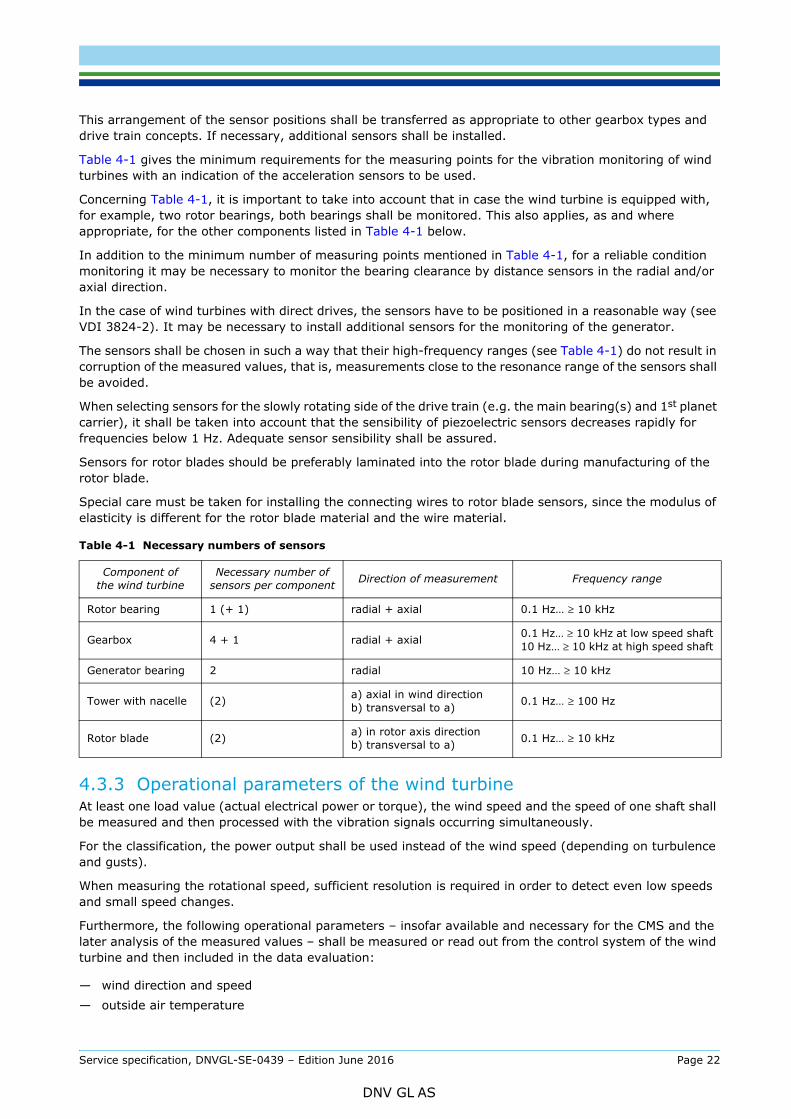
Table 4-1 gives the minimum requirements for the measuring points for the vibration monitoring of wind turbines with an indication of the acceleration sensors to be used.
Concerning Table 4-1, it is important to take into account that in case the wind turbine is equipped with, for example, two rotor bearings, both bearings shall be monitored. This also applies, as and where appropriate, for the other components listed in Table 4-1 below.
In addition to the minimum number of measuring points mentioned in Table 4-1, for a reliable condition monitoring it may be necessary to monitor the bearing clearance by distance sensors in the radial and/or axial direction.
In the case of wind turbines with direct drives, the sensors have to be positioned in a reasonable way (see VDI 3824-2). It may be necessary to install additional sensors for the monitoring of the generator.
The sensors shall be chosen in such a way that their high-frequency ranges (see Table 4-1) do not result in corruption of the measured values, that is, measurements close to the resonance range of the sensors shall be avoided.
When selecting sensors for the slowly rotating side of the drive train (e.g. the main bearing(s) and 1st planet carrier), it shall be taken into account that the sensibility of piezoelectric sensors decreases rapidly for frequencies below 1 Hz. Adequate sensor sensibility shall be assured.
Sensors for rotor blades should be preferably laminated into the rotor blade during manufacturing of the rotor blade.
Special care must be taken for installing the connecting wires to rotor blade sensors, since the modulus of elasticity is different for the rotor blade material and the wire material.
4.3.3 Operational parameters of the wind turbineAt least one load value (actual electrical power or torque), the wind speed and the speed of one shaft shall be measured and then processed with the vibration signals occurring simultaneously.
For the classification, the power output shall be used instead of the wind speed (depending on turbulence and gusts).
When measuring the rotational speed, sufficient resolution is required in order to detect even low speeds and small speed changes.
Furthermore, the following operational parameters – insofar available and necessary for the CMS and the later analysis of the measured values – shall be measured or read out from the control system of the wind turbine and then included in the data evaluation:
— wind direction and speed— outside air temperature
Table 4-1 Necessary numbers of sensors
Component of the wind turbine
Necessary number of sensors per component Direction of measurement Frequency range
Rotor bearing 1 (+ 1) radial + axial 0.1 Hz… ≥ 10 kHz
Gearbox 4 + 1 radial + axial 0.1 Hz… ≥ 10 kHz at low speed shaft10 Hz… ≥ 10 kHz at high speed shaft
Generator bearing 2 radial 10 Hz… ≥ 10 kHz
Tower with nacelle (2) a) axial in wind directionb) transversal to a) 0.1 Hz… ≥ 100 Hz
Rotor blade (2) a) in rotor axis direction b) transversal to a) 0.1 Hz… ≥ 10 kHz
Service specification, DNVGL-SE-0439 – Edition June 2016 Page 22
DNV GL AS
— temperatures of the main bearing and of the bearings in the gearbox, generator and converter— temperature of the generator windings— oil temperatures and pressure (e.g. hydraulic oil, gear oil)— messages about interventions in the control of the turbine (e.g. active yaw system, activated hydraulic
pump).
In the case of the gear oil, it is possible to obtain information about the wear of the gear by measuring the difference between the oil temperature at the inlet and the oil temperature at the outlet. An increase in the temperature difference is an indication for higher dissipative heat due to wear.
Monitoring the difference in rotation angle between the gearbox output shaft and the generator input shaft permits conclusions to be drawn about the load variations in the gearbox, and can also yield further useful findings.
Further data can be obtained from gear oil samples extracted regularly or from online measurements of the oil condition.
4.3.4 Measured particle parametersBesides the vibration parameters to be measured according to [4.3.2], the main gearbox can be monitored additionally through the continuous measurement of metallic particles in the gear oil.
The sensors to be used for this purpose shall be so positioned as to allow analysis of a defined, known volume flow of the gear oil during rated operation of the wind turbine. The gear oil shall be extracted from the lubricant cooling circuit upstream of the filter system.
Provision shall be made and documented that the output signal from the sensor can be used as an additional input signal for a CMS.
At least the time, operational situation of the turbine, oil temperature, and the size and material (ferrous/non-ferrous metal) of the particles shall be stored.
4.3.5 Measured oil cleanlinessBesides the vibration parameters to be measured according to [4.3.2], the main gearbox can be monitored additionally through the continuous measurement of the cleanliness of the gear oil according to ISO 4406.
The sensors to be used for this purpose shall be so positioned as to allow analysis of a defined, known volume flow of the gear oil during rated operation of the wind turbine. The gear oil shall be extracted from the lubricant cooling circuit upstream of the filter system.
Provision shall be made and documented that the output signal from the sensor can be used as an additional input signal for a CMS.
At least the time, operational situation of the turbine, oil temperature, and the cleanliness values according ISO 4406 shall be stored.
4.4 Handling of signals
4.4.1 GeneralThis section deals with the handling of the signals obtained from the vibration monitoring.
The commonly applicable rules for handling digital signals (e.g. concerning the sampling rate and anti-aliasing filtering) shall be applied. For example, according to the sampling theorem for the evaluation of structure-borne vibration, the sampling rate must be at least twice as high as the highest signal frequency, see VDI 3839-1, 2.
For measuring signals and for the signal analysis, ISO 5348, VDI 3839-1, 2 and ISO 13373-1 shall also be observed.
For analogue signal lines, adequate screening shall be provided.
Service specification, DNVGL-SE-0439 – Edition June 2016 Page 23
DNV GL AS

To acquire the vibration signals, at least eight fast input channels are required in order to comply with the requirements of [4.3.2]. In addition, a sufficient number of channels shall be provided for the input of operational parameters; see [4.3.3].
For the analysis of signals on the basis of operational data, the parameters to be evaluated shall be measured at the same time, so that it will be possible to establish both an operation-dependent relation and a temporal relation.
4.4.3 Signal processingFor the processing of signals, it is necessary to amplify and filter the acquired signals. This is necessary in order to distinguish in a clearer way between normal operation-dependent signals of the wind turbine and such signals resulting from abnormal conditions (e.g. damage, unbalance).
Rotation frequencies and defect frequencies of the roller bearings, as well as characteristic frequencies of the gear meshes shall be determined for each wind turbine. These shall then be transmitted to the MB.
It cannot be assumed in every case, that the installed roller bearings are identical in type and manufacturer to those listed in the documentation. Therefore the rotation frequencies and defect frequencies may vary slightly.
Operational parameters of the wind turbine which affect the vibration values, and which result from external or operation-dependent influences, shall be taken into account and filtered using adequate measures. The effects of these influences can also be found in the momentary power output of the wind turbine, in its rotational speed, as well as in the measured wind speeds.
For the separation, three different procedures can be used:
— operational-category concept— statistical vibration evaluation— vibration scaling in models.
For all three procedures, measurements have to be carried out at the corresponding wind turbine, in order to evaluate whether operation-dependent and condition-dependent vibrations were separated to the required degree.
Furthermore, [4.4.5] shall be observed.
4.4.4 Signal analysis4.4.4.1 Analysis proceduresIn Table 4-2 below, the required component-dependent analysis procedures are given. The following three sections provide further information on the corresponding components.
Moreover, it may be useful to log the amplitude of the measured values and the phase angle (rotor rotation angle) in addition; see [4.4.4.4].
4.4.4.2 Rolling bearingsGenerator bearings usually are roller bearings. In this case, broadband characteristic values from the structure-borne sound time signal and the envelope signal shall be used, and the envelope analysis shall be applied as the analysis procedure.
Compared with the frequency-selected characteristic values, broadband characteristic values from the structure-borne sound time signal are more useful at lower rotational speeds, e.g. for the speed of the rotor bearing or wind turbines with direct drives, or for low levels of structure-borne sound generated in components other than the roller bearing. When using broadband characteristic values from the structure-borne sound time signal, the measuring time is shorter compared to the frequency analysis, which requires a long measuring period in the case of slow speeds in order to obtain sufficient resolution. Apart from that, frequency and envelope analyses require a sufficiently long constant rotational speed, in order to guarantee the usefulness of the measured data.
Service specification, DNVGL-SE-0439 – Edition June 2016 Page 24
DNV GL AS
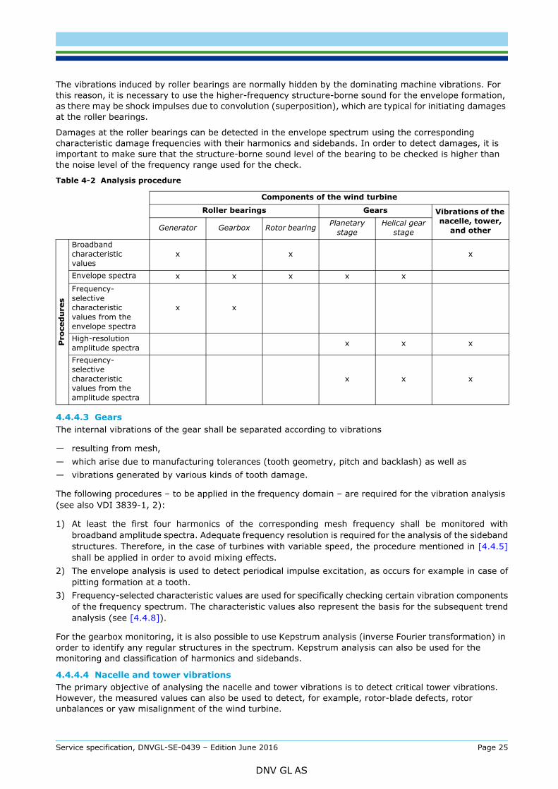
this reason, it is necessary to use the higher-frequency structure-borne sound for the envelope formation, as there may be shock impulses due to convolution (superposition), which are typical for initiating damages at the roller bearings.
Damages at the roller bearings can be detected in the envelope spectrum using the corresponding characteristic damage frequencies with their harmonics and sidebands. In order to detect damages, it is important to make sure that the structure-borne sound level of the bearing to be checked is higher than the noise level of the frequency range used for the check.
4.4.4.3 GearsThe internal vibrations of the gear shall be separated according to vibrations
— resulting from mesh,— which arise due to manufacturing tolerances (tooth geometry, pitch and backlash) as well as— vibrations generated by various kinds of tooth damage.
The following procedures – to be applied in the frequency domain – are required for the vibration analysis (see also VDI 3839-1, 2):
1) At least the first four harmonics of the corresponding mesh frequency shall be monitored withbroadband amplitude spectra. Adequate frequency resolution is required for the analysis of the sidebandstructures. Therefore, in the case of turbines with variable speed, the procedure mentioned in [4.4.5]shall be applied in order to avoid mixing effects.
2) The envelope analysis is used to detect periodical impulse excitation, as occurs for example in case ofpitting formation at a tooth.
3) Frequency-selected characteristic values are used for specifically checking certain vibration componentsof the frequency spectrum. The characteristic values also represent the basis for the subsequent trendanalysis (see [4.4.8]).
For the gearbox monitoring, it is also possible to use Kepstrum analysis (inverse Fourier transformation) in order to identify any regular structures in the spectrum. Kepstrum analysis can also be used for the monitoring and classification of harmonics and sidebands.
4.4.4.4 Nacelle and tower vibrationsThe primary objective of analysing the nacelle and tower vibrations is to detect critical tower vibrations. However, the measured values can also be used to detect, for example, rotor-blade defects, rotor unbalances or yaw misalignment of the wind turbine.
Table 4-2 Analysis procedure
Components of the wind turbine
Roller bearings Gears Vibrations of the nacelle, tower,
and other Generator Gearbox Rotor bearing Planetary stage
Helical gear stage
Pro
ced
ure
s
Broadband characteristic values
x x x
Envelope spectra x x x x x
Frequency-selective characteristic values from the envelope spectra
x x
High-resolution amplitude spectra x x x
Frequency-selective characteristic values from the amplitude spectra
x x x
Service specification, DNVGL-SE-0439 – Edition June 2016 Page 25
DNV GL AS

direction) and transversal (transversely to the wind direction) directions, which require sufficient sensor sensibility in the low-frequency range.
For the analysis of the measured data, it is recommendable to consider the corresponding phase angles (rotor rotation angles), apart from the amplitudes, in order to narrow down the cause of the damage further.
4.4.5 Speed variationsSpeed variations, as occur in the case of variable-speed wind turbines, affect on the one hand the vibration behaviour of the wind turbine; however, on the other hand they result in a shifting of the kinematic excitation frequencies. For this reason, the frequencies can no longer be clearly separated during analyses in the frequency domain.
It is therefore necessary to use special procedures in such cases. In the following, three possible procedures are mentioned; these depend on the intensity of the speed variations.
1) Speed limits
In the case of wind turbines with rare speed variations that occur slowly, this procedure produces usefulresults. The speed limits are chosen in such a way that, despite these speed variations, the results ofthe analyses still make it possible to draw correct conclusions.
2) Short-time Fourier transform
For this procedure too, rapid speed variations will negatively affect the usefulness of the results of theanalysis.
3) Order analysis
For wind turbines with fast speed variations, the best procedure is to generate frequency spectra in theform of order spectra. In this case, a speed-dependent resampling will be carried out for the recordedtime data prior to the frequency analysis, i.e. the time data will be recorded with a speed-dependentsampling frequency (triggering). The frequency axis will be scaled in accordance with the harmonics(orders) of the rotary frequency.
4.4.6 AveragingThe averaging of characteristic vibration values should be avoided, in order to obtain detailed trend information. In the case of the frequency spectra, however, averaging may be useful, in order to highlight repeated effects and to minimize possible operation-dependent deviations in the individual spectrum.
In all these cases, it is important to ensure that no significant data, which could be necessary for the interpretation of the measured values, are lost due to the determination of average values; see also [4.5].
4.4.7 Limiting valuesAn appropriate method for the determination of limiting values is required for each of the analysis procedures mentioned above. The alarm messages (see also [4.6]) shall be generated in at least two steps, with a limiting-value pre-alarm (warning) and the main alarm.
For the determination of the limiting values, the CMS shall offer a function which automatically calculates the limiting values on the basis of definable safety levels using the data from the reference measuring phase. However, it shall also be possible to manually modify the limiting values computed by the CMS, in order to react appropriately to new operational situations (e.g. replaced gearbox bearings) and to adapt the limiting values correspondingly.
The limiting values listed in VDI 3834-1, 2 are not suitable for using them as limiting values for monitoring the drive train.
In turbines with variable speed, it shall be described how the CMS guarantees the monitoring in respect of speed variability.
Service specification, DNVGL-SE-0439 – Edition June 2016 Page 26
DNV GL AS
Trend analysis makes it possible to visualize the temporal development of the characteristic values, and to decide about the necessary measures to be taken. In order to do so, the individual characteristic values are represented as a function of time, taking into account the operational influences.
Apart from this, trends can be recognized, for example, in the vibration behaviour of the wind turbine or of individual components, before limiting values are exceeded.
In order to conduct an informative and useful trend analysis, the measured data of at least one year is required. Thinning out the measured data reduces their information value and makes it more difficult to analyse and interpret the results.
For the trend analysis, it is recommended to have access to a database.
4.5 Data storageIn order to be able to consult a large database for evaluating the condition, the calculated characteristic values and spectra shall be stored, even if no limiting value was transgressed.
Automatic data reduction shall be avoided. For the reduction of data, the corresponding criteria shall be determined. As a rule, data reduction prior to the analysis by the CMS is to be avoided.
During the storage process, it is important to store only data obtained under comparable and meaningful constraints (e.g. the same output range, comparable operational conditions). These constraints shall be indicated and stored together with the data.
Appropriate storage intervals shall be determined, depending on the meaningfulness and importance of the measured data. It may, for example, be reasonable to store data once a day for the trend analysis, taking into account the external conditions.
Using adequate procedures, such as the regular transfer of data to a host computer, the storage capacity on site can be kept small. Data may, for example, be archived at the MB.
Data from the first measuring period will be needed as reference values for the interpretation of subsequently measured values. The same applies for data measured after relevant repairs or modifications to the wind turbines or to their components.
For the measurements carried out during the first measuring phase, the raw data (sampled analog sensor signals) shall also be stored together with information concerning the external physical conditions.
In addition, raw data in all the evaluation windows that are used shall be stored at least once a day.
Due to the great importance of data storage and archiving, these functions shall be included in the annual maintenance inspections.
A storage concept shall be presented for the certification which prevents the loss of important data required for the interpretation of the measured results.
For semi-integrated or fully integrated CMS is shall be observed that the storage of CMS data is independent from the storage of data from the control system.
For the data transfer to the MB, it shall be taken into account that in some cases only telephone lines are available. It may be recommendable to install a server in the wind farm which carries out the analysis and afterwards transfers the analysed data to the MB.
4.6 Alarm functionsThe CMS shall inform the MB and, if necessary, other responsible areas about limiting value transgressions (see also [4.4.7]) immediately and automatically using both a pre-alarm and main alarm, in the form of alarm messages with indications concerning the type, cause, place and time of the limiting value transgressions. Possible ways of transmitting the message are e.g. e-mail or SMS.
Alarm messages shall be stored together with all the parameters of the turbine and protected against unauthorized access.
As soon as an alarm message is cleared, this shall be automatically recorded in a list, together with indications concerning the limiting value and the identification of the person clearing the alarm message.
Service specification, DNVGL-SE-0439 – Edition June 2016 Page 27
DNV GL AS

be cleared within a certain time window. This number shall be stipulated in each individual case, on the basis of the turbine-specific adaptation of the system in dependence of the type of the wind turbine, the type of the CMS and the measuring point.
As soon as the maximum number of alarm clearances is reached, no new clearance will be possible. Instead, the alarm will persist. In this way, it will not be possible for repeated alarm messages with the same cause to be overlooked or ignored.
4.7 DiagnosisAfter the automatic message informing about a limiting value transgression, the necessary evaluation and interpretation of the change shall follow. Although the CMS may have detected a change in the condition of the wind turbine or a component, the examination to determine to what degree this change is relevant and what further measures need to be taken shall be carried out by the specialists of the MB; see [2.2.3.2].
In order to analyse the cause of the limiting value transgression, it shall be possible to access the CMS to evaluate the stored data and to allow, if necessary, separate measurements independently of the trigger conditions.
For the diagnosis, it shall be possible to control the CMS by remote control as well as on site. In order to do this, the CMS shall be equipped with the following auxiliary devices:
— A graphic guide shall be provided to the measuring point and to the characteristic value of the limiting value transgression.
— It shall be possible to open a trend plot which takes into account the operational parameters of the wind turbine. It is necessary to portray several parameters (e.g. the vibration values of various components and the operational parameters of the wind turbine) in a diagram e.g. as a function of time.
— A tool shall be provided for calculating the kinematic component-dependent excitation frequencies of the wind turbine.
— Automatic, graphic generation of the relationship between certain frequencies and possible components shall be provided. Manual comparison, e.g. using lists, is not admissible.
At the end of the diagnosis, the specialist of the MB shall communicate his decision to the operator of the wind turbine and recommend protective measures.
During the particle measurement (see [4.3.4]), the trend shall be displayed as a function of time and also in connection with the corresponding turbine output.
During the oil cleanliness measurement (see [4.3.5]), the trend shall be displayed as a function of the time.
The results and measures shall be documented at the MB in a comprehensible way and at least in written form.
Service specification, DNVGL-SE-0439 – Edition June 2016 Page 28
DNV GL AS
5.1 Installation manual for the condition monitoring system
5.1.1 GeneralThe installation manual describes all the working steps to be taken during the installation of the CMS at the place of installation, i.e. at the site of the wind turbine, in order to ensure safe operation of the CMS.
The installation manual is only valid for one type of a CMS; in certain cases, the manual may also be valid for its different versions.
A copy of the completed installation record shall be submitted to the operator of the wind turbine and the responsible MB; see [5.1.3.5].
5.1.2 Format of the installation manualThe format and level of detail of the installation manual shall be such that the technical personnel in charge of the installation are able to understand the documentation.
The installation manual shall be also expressed in a language – apart from English – which can be understood by the technical personnel performing the required tasks at the installation site of the CMS.
Safety instructions and regulations for the prevention of accidents shall be placed in the text in such a way that they appear before the corresponding step to be carried out. They shall be highlighted in order to be easily recognized as such.
5.1.3 Scope of the installation manualAt least the following indications shall be included in the installation manual:
— precise designation of the type of the CMS (see [5.1.3.1])— prerequisites for the installation (see [5.1.3.2])— working steps to be followed during the installation (see [5.1.3.3])— warnings against hazardous situations (see [5.1.3.4])— form sheet for the installation record (see [5.1.3.5]).
5.1.3.1 Type designation of the condition monitoring systemAt least the following information shall be provided:
— manufacturer, supplier, importer— designation, type and, if applicable, type variant.
5.1.3.2 Prerequisites for the installationAll the prerequisites for proper execution of the installation shall be specified.
5.1.3.3 Working steps for installationAll the working steps required for the installation shall be described. Auxiliary devices or tools shall be specified precisely.
All the required tests and assessments shall be listed.
5.1.3.4 Warnings against hazardous situationsAll the situations that could arise if the installation does not proceed as planned shall be mentioned. The measures to be taken in each case shall be indicated.
5.1.3.5 Form sheet of the installation recordThe installation record is used to document the proper execution of all the checks and working steps of the installation process. For each check and working step, there shall be appropriate fields to be filled in, together with fields for entering the measured values, assessment results and short sign of person, who carried out the corresponding working step.
Service specification, DNVGL-SE-0439 – Edition June 2016 Page 29
DNV GL AS
The installation record may consist of various sub-records (e.g. for various assemblies or installation phases).
The following fields shall be provided as a minimum:
— type designation of the CMS according to [5.1.3.1], including the serial number— details of the wind turbine (manufacturer, type, serial number and site)— name of the person(s) carrying out the corresponding working step— record of the execution of all the working steps according to [5.1.3.3]— documentation of the sensor positions with photos— extra space for possible remarks or items outstanding— date and signature of the person(s) responsible for the installation.
5.2 Documents for the commissioning of the condition monitoring system
5.2.1 Commissioning manualThe commissioning manual describes all working steps which have to be performed during commissioning in order to ensure safe operation of the CMS.
The commissioning manual is valid for only one type of a CMS.
A copy of the completed commissioning record shall be submitted to the operator of the wind turbine and to the responsible MB; see [5.2.4.4].
5.2.2 Commissioning recordThe commissioning record documents the execution of the individual working steps during the commissioning process. A blank form sheet of the commissioning record shall be included in the commissioning manual.
5.2.3 Format of the documentsThe format and level of detail of the commissioning manual shall be such that the technical personnel performing the required tasks are able to understand the documentation.
The commissioning manual shall also be expressed – apart from English – in a language which can be understood by the personnel performing the commissioning of the CMS.
Safety instructions and regulations for the prevention of accidents shall be placed in the text in such a way that they appear before the corresponding step to be carried out. They shall be highlighted in order to be easily recognized as such.
5.2.4 Scope of the commissioning manualThe commissioning manual shall contain the following information as a minimum:
— precise type designation of the CMS (see [5.2.4.1])— checks required before start of commissioning (see [5.2.4.2])— working steps of the commissioning process (see [5.2.4.3])— blank form sheets for the commissioning record (see [5.2.4.4]).
5.2.4.1 Type designation of the CMSAt least the following information shall be provided:
— manufacturer, supplier, importer— designation, type and, if applicable, type variant.
Service specification, DNVGL-SE-0439 – Edition June 2016 Page 30
DNV GL AS

All the checks to be carried out prior to the commissioning shall be listed.
5.2.4.3 Working steps for the commissioningAll the working steps required for the commissioning shall be described. For the commissioning of individual assemblies, reference may be made to subordinate commissioning manuals for such assemblies.
All the prerequisites for the proper execution of commissioning shall be specified.
Tests for all the functions of the CMS shall be described. The switching values to be set and criteria to be met shall be specified.
At least the following tests shall be carried out, taking into account [2.2.2.5]:
— function of all sensors and switches— test to verify that the functions responding to the activation of the safety system are independent of the
CMS— assessment of all the set limiting values for the initial measuring phase— plausibility check of the behaviour of the wind turbine— plausibility check of the measured values— synchronization of the system clocks— familiarization of the operator and the MB of the CMS.
5.2.4.4 Form sheet for the commissioning recordThe commissioning record is used to document the proper execution of all the checks and working steps of the commissioning process. For each check and working step, there shall be appropriate fields to be filled in, together with fields for entering the measured values, assessment results and short sign of person, who carried out the corresponding working step.
All the set values and nominal values, as well as expected measured values, shall be specified.
The commissioning record may consist of several sub-records.
The following fields shall be provided as a minimum:
— type designation of the CMS as per [5.2.4.1], including the serial number— details of the wind turbine (manufacturer, type, serial number and site)— persons present during commissioning— confirmation that all checks required before the start of commissioning as per [5.2.4.2] have been
completed— record of the execution of all working steps of the commissioning as per [5.2.4.3]— extra space for possible remarks or items outstanding— date and signature of the person(s) responsible for the commissioning.
5.3 Operating manual for the condition monitoring system
5.3.1 Purpose of the operating manualThe operating manual is intended to provide the operator or his representative, such as the MB, with the knowledge necessary for proper operating of the CMS.
5.3.2 Format of the operating manualThe format and level of detail of the operating manual shall be such that a skilled workman with technical training is able to understand the documents. Safety instructions and regulations for the prevention of accidents shall be so arranged in the text that they appear before the operating action in question. They shall be highlighted in order to be easily recognized as such.
The operating manual shall be also provided in a language – apart from English – that can be understood by the technical personnel at the installation site of the CMS.
Service specification, DNVGL-SE-0439 – Edition June 2016 Page 31
DNV GL AS
under which the turbine and the CMS is operated. This applies particularly to notices affixed directly to the turbine.
5.3.3 Scope of the operating manualThe operating manual shall contain the following information:
— description of the CMS
— notes for users
— help with troubleshooting.
5.3.3.1 Description of the CMS
— manufacturer, supplier, importer
— designation, type and, if applicable, type variant(s)
— manufacturer’s number or serial number, as well as year of manufacture
— technical data
— description of the software and evaluation algorithms used
— description of the operating mode.
5.3.3.2 Notes for users
— notes on the evaluation tools
— explanation of the error messages
— safety measures
— accident prevention regulations
— description of the functions and modes of all the control elements, display elements and software elements required for the operation
— explanations of malfunctions and how to rectify them.
5.3.3.3 Help with troubleshootingWithout carrying out any repairs himself, the expert of the MB shall be capable of recognizing the cause of a malfunction and – insofar as it cannot be rectified simply by an operating action – of providing the maintenance personnel with useful advance information.
5.4 Maintenance manual for the condition monitoring system
5.4.1 GeneralThe maintenance manual contains the instructions for maintenance, inspection and repair, as defined in DIN 31051 or an equivalent standard recognized by DNV GL.
5.4.2 Purpose of the maintenance manualThe maintenance manual is intended to provide the maintenance personnel with the information necessary for maintenance, inspection and repair.
5.4.3 Format of the maintenance manualWith regard to its contents and form, the maintenance manual shall meet the requirements expressed in [5.3.2].
It is recommended to compile a maintenance and inspection plan presenting the work required in tabular form and in the appropriate time sequence.
In addition, DIN 31051 or an equivalent standard recognized by DNV GL shall be observed.
Service specification, DNVGL-SE-0439 – Edition June 2016 Page 32
DNV GL AS

The maintenance manual shall contain the following information; DIN 31051 or an equivalent standard recognized by GL shall be observed in addition.
— Information documenting the correspondence between the maintenance manual and the CMS (see [5.3.3.1].
— Notes on safety measures and accident prevention to be observed before and during maintenance.— Descriptions of all tasks to be carried out.— All components of the CMS which have to be replaced according to a schedule during the operating
period, or which require special inspections/assessments, shall be listed. The criteria for the replacement or inspections/assessment as well as the required time intervals shall be specified.
The perfect operation of the data storage and archiving shall be assessed once a year.
Furthermore, information shall be given about the quality and quantity of the spare parts to be used (spare parts list).
The maintenance manual shall be supplemented by a maintenance and inspection plan defining the tasks to be carried out at set intervals. On completion, the tasks shall be recorded in this plan.
A detailed listing and description of the required tests shall be included in the maintenance manual. The required frequency of these tests (e.g. annually) shall be indicated. The completion of the tests shall be recorded in the maintenance and inspection plan.
Service specification, DNVGL-SE-0439 – Edition June 2016 Page 33
DNV GL AS
TYPE CERTIFICATE Certificate No.: Issued: Valid until:TC-DNVGL-SE-0439-[ID with 5 digits]-[rev.] [YYYY]-[MM]-[DD] [YYYY]-[MM]-[DD]
Issued for:
<Condition Monitoring System Type>
Issued to:
<CMS Manufacturer>< Address line >< Address line >
According to:
DNVGL-SE-0439:2016-05 Certification of condition monitoring
Based on the documents:CR-DNVGL-SE-0439-[ID with 5 digits]-[rev.] Certification Report [Condition Monitoring System Type],
dated yyyy-mm-dd
Changes of the system design, the production or the manufacturer’s quality system are to be approved by DNV GL.
Place, yyyy-mm-dd Place, yyyy-mm-dd
For DNV GL Renewables Certification For DNV GL Renewables Certification
[Name of SLL for “Cert. decision”][Function]
By DAkkS according DIN EN IEC/ISO 17065 accredited Certification Body for products. Theaccreditation is valid for the fields of certificationlisted in the certificate.
[Name of PM “doing it”][Function]
The accredited certification body is Germanischer Lloyd Industrial Services GmbH, Brooktorkai 18, 20457 Hamburg.DNV GL Renewables Certification is the trading name of DNV GL’s certification business in the renewable energy industry.
Service specification, DNVGL-SE-0439 – Edition June 2016 Page 34
DNV GL AS

CONFORMITY STATEMENT Statement No.: Issued: Valid until:MB-DNVGL-SE-0439-[ID with 5 digits]-[rev.] [YYYY]-[MM]-[DD] [YYYY]-[MM]-[DD]
Issued for:
<Monitoring Body>
Issued to:
<Company Name>< Address line >< Address line >
According to:
DNVGL-SE-0439:2016-05 Certification of condition monitoring
Based on the documents:CR-DNVGL-SE-0439-[ID with 5 digits]-[rev.] Certification Report [Monitoring Body],
dated yyyy-mm-ddCR-DNVGL-SE-0439-[ID with 5 digits]-[rev.] Certification Report [Condition Monitoring System Type],
dated yyyy-mm-dd
Changes of the supervision method or the quality management system are to be approved by DNV GL.
Place, yyyy-mm-dd Place, yyyy-mm-dd
For DNV GL Renewables Certification For DNV GL Renewables Certification
[Name of SLL for “Cert. decision”][Function]
By DAkkS according DIN EN IEC/ISO 17065 accredited Certification Body for products. Theaccreditation is valid for the fields of certificationlisted in the certificate.
[Name of PM “doing it”][Function]
The accredited certification body is Germanischer Lloyd Industrial Services GmbH, Brooktorkai 18, 20457 Hamburg.DNV GL Renewables Certification is the trading name of DNV GL’s certification business in the renewable energy industry.
Service specification, DNVGL-SE-0439 – Edition June 2016 Page 35
DNV GL AS

SAF
DNV GLDriven by our purpose of safeguarding life, property and the environment, DNV GL enables organizations to advance the safety and sustainability of their business. We provide classification and technical assurance along with software and independent expert advisory services to the maritime, oil and gas, and energy industries. We also provide certification services to customers across a wide range of industries. Operating in more than 100 countries, our 16 000 professionals are dedicated to helping our customers make the world safer, smarter and greener.
ER, SMARTER, GREENER