do not destroy no destruir i n s t a l l a t i o n m a n u a l · 4 introduction this manual...
TRANSCRIPT

I n s t a l l a t i o na n d
M a i n t e n a n c eM a n u a l
with Safety Information
and Parts ListRECOMMENDED SPARE PARTS HIGHLIGHTED IN GRAY
IMPORTANT!DO NOT DESTROY
Model 138-ACC, LRCLRS, & LRSS
HYTROL CONVEYOR CO., INC.© COPYRIGHT 2007–HYTROL CONVEYOR CO., INC.
Jonesboro, Arkansas
Effective February 2007(Supercedes February 2004)
Bulletin # 583
IMPORTANTE!NO DESTRUIR
M a n u a lde Instalación
yM a n t e n i m i e n t o
con Información sobre Seguridad
y Lista de PartesPARTES DE REPUESTO RECOMENDADAS SE RESALTAN EN GRIS
138-ACC 138-LRC

2
● Table of Contents ● Tabla de ContenidoWarning Signs . . . . . . . . . . . . . . . . . . . . .3
INTRODUCTIONReceiving and Uncrating . . . . . . . . . . . . .4
INSTALLATIONInstallation Safety Precautions . . . . . . . .4Support Installation . . . . . . . . . . . . . . . . .5Ceiling Hanger Installation . . . . . . . . . . .6Conveyor Set-Up . . . . . . . . . . . . . . . . . . .7Connecting the V-Belts . . . . . . . . . . . . . .8Racked Sections . . . . . . . . . . . . . . . . . .10Slave Driven Curve or Spur . . . . . . . . .11Pressure Adjustment . . . . . . . . . . . . . . .12Electrical Equipment . . . . . . . . . . . . . . .14
OPERATIONOperation Safety Precautions . . . . . . . .16Conveyor Start-Up . . . . . . . . . . . . . . . .16
MAINTENANCEMaintenance Safety Precautions . . . . .17Lubrication . . . . . . . . . . . . . . . . . . . . . . .17Belt Replacement . . . . . . . . . . . . . . . . .18Belt Tension Adjustment . . . . . . . . . . . .20Drive Chain Alignment and Tension . . .21Trouble Shooting . . . . . . . . . . . . . . . . .22 Maintenance Checklist . . . . . . . . . . . . .24
REPLACEMENT PARTSHow To Order Replacement Parts . . . .25138-ACC Parts Drawing & List . . . . . . .26LRC-90° Parts Drawing & List . . . . . . .28LRC-60° Parts Drawing & List . . . . . . .30LRC-45° Parts Drawing & List . . . . . . .32LRC-30° Parts Drawing & List . . . . . . .34LRS-45° Parts Drawing & List . . . . . . . .36LRS-30° Parts Drawing & List . . . . . . . .38LRSS-45° Parts Drawing & List . . . . . .40LRSS-30° Parts Drawing & List . . . . . .42138-ACC Sheave Retainers . . . . . . . . .44LRC,LRS, & LRSS Sheave Retainers .45Slave Connection Parts Drawing . . . . .46
Señales de Advertencia . . . . . . . . . . . . .3INTRODUCCION
Recepción y Desembalaje . . . . . . . . . . .4INSTALACION
Medidas de Seguridad al Instalar . . . . .4Instalación de los Soportes . . . . . . . . . . .5Instalación de los Soportes de Techo . . .6Montaje . . . . . . . . . . . . . . . . . . . . . . . . . .7Conectando las Bandas-V . . . . . . . . . . .8Secciones Descuadradas . . . . . . . . . . .10Curva o Espuela Motriz Esclavada . . . .11Ajuste de Presión . . . . . . . . . . . . . . . . .12Equipo Eléctrico . . . . . . . . . . . . . . . . . .14
OPERACIONSeguridad en la Operación . . . . . . . . . .16Arranque del Transportador . . . . . . . . .16
MAINTENIMIENTOSeguridad en el Mantenimiento . . . . . .17Lubricación . . . . . . . . . . . . . . . . . . . . . .17Reemplazo de la Banda . . . . . . . . . . . .18Tensión de la Banda . . . . . . . . . . . . . . .20Alineación y Tensión de la Cadena . . .21Resolviendo Problemas . . . . . . . . . . . .22 Lista de Mantenimiento Preventivo . . . .24
PARTES DE REPUESTOComo Ordenar Repuestos . . . . . . . . . .25138-ACC Dibujo & Lista de Partes . . . .26LRC-90° Dibujo & Lista de Partes . . . .28LRC-60° Dibujo & Lista de Partes . . . .30LRC-45° Dibujo & Lista de Partes . . . .32LRC-30° Dibujo & Lista de Partes . . . .34LRS-45° Dibujo & Lista de Partes . . . .36LRS-30° Dibujo & Lista de Partes . . . .38LRSS-45° Dibujo & Lista de Partes . . .40LRSS-30° Dibujo & Lista de Partes . . .42Retenedores de Polea 138-ACC . . . . .44Retenedores LRC,LRS, & LRSS . . . . .45Conexión Esclavada . . . . . . . . . . . . . . .46

3
In an effort to reduce the possibility of injury to personnelworking around HYTROL conveying equipment, warningsigns are placed at various points on the equipment to alertthem of potential dangers. Please check equipment andnote all warning signs. Make certain your personnel arealerted to and obey these warnings. Shown below are typ-ical signs that are attached to this equipment.
En un esfuerzo por reducir la posibilidad de accidentes alpersonal trabajando junto al equipo de transportaciónHYTROL, se colocan señales de advertencia en diferentespuntos del equipo para alertarlos de riesgos potenciales.Por favor verifique el equipo y asegúrese de ver todas lasseñales de advertencia. Asegúrese de que su personal estéalerta y obedezca las señales. Abajo se muestran señalestípicas que se encuentran en este equipo.
● Warning Signs ● Señales de A d v e r t e n c i a
PLACED ON ALL POWEREDCONVEYORS NEAR DRIVE
AND/OR CONTROLS.
PLACED NEXT TO DRIVE, BOTHSIDES.
PLACED ON 20 FT.INTERVALS,BOTH SIDES.
PLACED AT DRIVE OF ALLPOWERED CONVEYORS.PLACED ON TERMINATING ENDS.
COLOCADAS EN TODOS LOSTRANSPORTADORES
MOTORIZADOS CERCA ALMOTOR Y/O LOS CONTROLES
COLOCADAS EN LA UNIDADMOTRIZ DE TODOS LOS TRANS -PORTADORES MOTORIZADOS.
COLOCADAS EN INTERVALOS DE20 PIES, A AMBOS LADOS.
COLOCADAS EN LOS EXTREMOS.
COLOCADAS JUNTO A LA UNIDADMOTRIZ, EN AMBOS LADOS.
PLACED ON ALL CHAIN GUARDS. COLOCADAS EN TODAS LASGUARDA CADENAS.

4
INTRODUCTIONThis manual provides guidelines and procedures forinstalling, operating, and maintaining your conveyor. Acomplete parts list is provided with recommended spareparts highlighted in gray. Important safety information isalso provided throughout the manual. For safety to person-nel and for proper operation of your conveyor, it is recom-mended that you read and follow the instructions providedin this manual.
Check the number of items received against the bill oflading.Examine condition of equipment to determine if anydamage occurred during shipment.Move all crates to area of installation.Remove crating and check for optional equipment thatmay be fastened to the conveyor. Make sure theseparts (or any foreign pieces) are removed.
NOTE: If damage has occurred or freight is missing, seethe “Important Notice” attached to the crate.
INSTALLATION
GUARDS AND GUARDINGInterfacing of Equipment. When two or more pieces of equip-ment are interfaced, special attention shall be given to the inter-faced area to insure the presence of adequate guarding and safe-ty devices.Guarding Exceptions. Wherever conditions prevail that wouldrequire guarding under these standards, but such guarding wouldrender the conveyor unusable, prominent warning means shallbe provided in the area or on the equipment in lieu of guarding.Guarded by Location or Position. Where necessary for theprotection of employees from hazards, all exposed movingmachinery parts that present a hazard to employees at their workstation shall be mechanically or electrically guarded, or guardedby location or position.When a conveyor passes over a walkway, roadway, or work sta-tion, it is considered guarded solely by location or position if allmoving parts are at least 8 ft. (2.44 m) above the floor or walkingsurface or are otherwise located so that the employee cannot
1. . .
2. . .
3. . .4. . .
● Installation Safety Pr e c a u t i o n sfor Conveyors and Related Equipment
I N T R O D U C C I O NEste manual provee las pautas y los procedimientos parainstalar, operar, y mantener su transportador. Se propor -ciona una lista completa de repuestos, de los cuales, losrecomendados, estarán resaltados en gris. También se pro -porciona información importante de seguridad a lo largo deeste manual. Para seguridad del personal y para un fun -cionamiento apropiado del transportador, se recomiendaque lea y siga las instrucciones proporcionadas en estemanual.
NOTA: Si algún daño ha ocurrido o falta cargamento,vea las “Notas Importantes” adheridas al embalaje.
INSTALACION
GUARDAS Y PROTECCIONES Union del Equipo. Cuando dos o más piezas del equipo vanunidas, debe ponerse especial atención al área de union paraasegurar que las guardas adecuadas y los dispositivos de seguri -dad estén presentes.Excepciones de Protección. Dondequiera que las guardassean necesarias, pero que la colocación de las mismas inhabiliteel uso del transportador, se proporcionarán señales de adverten -cia visibles en el área o en el equipo en vez de las guardas.Protección dada por Posición o Ubicación. Cuando seanecesária la protección de los empleados contra posibles ries -gos, todas las partes del equipo que estén expuestas y enmovimiento, y que puedan presentar un peligro para ellos en suspuestos de trabajo, serán protegidas mecánica o eléctricamente,o protegidas por su posición o ubicación.Cuando el transportador está instalado sobre pasillos, corredoreso puestos de trabajo, se considera que está protegido única -mente por localización o posición si todas las partes en
● Medidas de Seguridad al InstalarTransportadores y Equipos Relacionados
● Receiving and Uncrating ● Recepción y Desembalaje Verifique el número de partes recibidas con elconocimiento del embarque.Examine las condiciones del equipo para determinar sialgún daño ha ocurrido durante la transportación.Mueva todo el equipo hacia el área de instalación.Remueva todos los empaques y verifique si hay partesopcionales que deben estar atadas al equipo.Asegúrese de que estas partes (o cualquier otraspartes externas) sean removidas.
1. . .
2. . .
3. . .4. . .

5
inadvertently come in contact with hazardous moving parts.Although overhead conveyors may be guarded by location, spillguard, pan guards, or equivalent shall be provided if the productmay fall off the conveyor for any reason and if personnel wouldbe endangered.
H E A D R O O MWhen conveyors are installed above exit passageways, aisles, orcorridors, there shall be provided a minimum clearance of 6 ft. 8in. (2.032 m) measured vertically from the floor or walking surfaceto the lowest part of the conveyor or guards.Where system function will be impaired by providing the minimumclearance of 6 ft. 8 in. (2.032 m) through an emergency exit, alter-nate passageways shall be provided.It is permissible to allow passage under conveyors with less than6 ft. 8 in. (2.032 m) clearance from the floor for other than emer-gency exits if a suitable warning indicates low headroom.
movimiento están mínimo a 8 pies (2.44m) de altura del piso, osi está localizado de tal manera que el empleado no pueda entraren contacto inadvertidamente con dichas partes.A pesar de que los transportadores áereos pueden estar protegi -dos por su localización, guardas laterales e inferiores deben serproporcionadas para evitar que el producto se caiga del trans -portador y así mantener al personal fuera de peligro.
UBICACION SUPERIORCuando los transportadores son instalados sobre pasillos ocorredores de salida, debe dejarse un espacio libre de mínimo 6pies 8 pulgadas (2,032m) de extensión, medido verticalmentedesde el piso o área de tránsito hasta la parte más baja del trans -portador o de las guardas.Si se proporcionan señales de advertencia adequadas indicandobaja altura; es posible dejar espacio libre con menos de 6 pies 8pulgadas (2.032m) de extensión entre el piso y el transportadoren los pasillos que no sean salidas de emergencia.
Determine primary direction of product flow. Figure 5Aindicates the preferred flow as related to the drive.Refer to “Match-Mark” numbers on ends of conveyorsections. (Figure 5A).Attach supports to both ends of drive section and toone end of intermediate or tail sections (Figure 5A).Hand tighten bolts only at this time. Adjust elevation to required height.
Determine la dirección primaria del flujo del producto.La figura 5A indica el flujo preferido en relación con launidad motriz.Refiérase a las “Etiquetas de Secuencia de Armado”situadas al final de las secciones del transportador.(Figura 5A).Fije los soportes en ambos extremos de la secciónmotriz y a un extremo de la sección intermedia o final(Figura 5A). Apriete los tornillos manualmente.Ajuste la elevación a la altura requerida.
DRIVE SECTIONINTERMEDIATE SECTION
ADJUST TO DESIREDELEVATION
(FLUJO DEL PRODUCTO)
(SECCION INTERMEDIA) (SECCION MOTRIZ)
(AJUSTE A LA ELEVACIONDESEADA)
(ETIQUETAS DE SECUENCIA DE ARMADO)
● Support Installation
FIGURE 5A
1. . .
2. . .
3. . .
4. . .
1. . .
2. . .
3. . .
4. . .
4”
2”2”
“MATCH-MARK” NUMBERS
TAIL SECTION
PRODUCT FLOWFLOW
(SECCION DE RETORNO)TAIL SECTION
(SECCION DE RETORNO)
● Instalación de los Soportes

6
If conveyors are to be used in an overhead application, ceil-ing hangers may have been supplied in place of floor sup-ports.
Figure 6A shows how a ceiling hanger mounts to a convey-or section. Ceiling hangers should be mounted at sectionjoints. For safety information concerning conveyors mount-ed overhead, refer to “Installation Safety Precautions” onPage 4.
NOTE: When installing ceiling hanger rods in an existingbuilding, all methods of attachment must comply withlocal building codes.
● Ceiling Hanger Installation
FIGURE 6A
Si los transportadores van a ser usados en aplicacionesaéreas o superiores, soportes colgantes del techo pudieronhaber sido suministrados en vez de los soportes de piso.
La Figura 6A muestra como un soporte colgante de techose instala en un transportador. Los soportes colgantesdeben montarse en la unión de las secciones. Para infor -mación de seguridad respecto al montaje de transporta -dores aéreos, refiérase a “Medidas de Seguridad alInstalar” en la página 4.
NOTA: Cuando se instalan varillas colgantes al techo enuna construcción existente, todos los métodos de unióndeben cumplir con los códigos locales de construcción.
● Instalación de losSoportes de Techo
(CANAL LATERAL)
(ABRAZADERA)
(TORNILLO CANDADO)
(CONTRA TUERCA)
(TUBO DE SOPORTE)
(CONTRA TUERCA)
(ESPACIADOR)SPACER
SIDE CHANNEL
JAM NUT
SUPPORT PIPE
JAM NUT
LOCK BOLT
PIPE RETAINER
(TORNILLO DE MONTAJE)MOUNTING BOLTS
(VARILLA COLGANTEAL TECHO)
CEILING HANGER ROD

7
● Conveyor Set-Up ● MontajeRe-check the “match-mark” numbers to see that adjoiningsections are in proper sequence and follow these stepsbelow to set up the conveyor.
Mark a chalk line on floor to locate center of the con-veyor. (Floor Mounted Conveyors).Place the drive section in position.Install remaining sections placing end without supporton extend pivot plate of previous section (Figure 7B).Complete installation of Joint V-Belt Shield (item 54 inParts List on Page 27): 1) Remove top bolt from buttcoupling on v-belt side of adjoining section, 2) Joinsections, and 3) Reinstall bolt through butt coupling,side channel, and v-belt shield.Fasten sections together with butt couplings andpivot plates (Figure 7A). Hand tighten bolts only atthis time.Connect V-belts per instructions on Page 8.Check to see that all “ACC” bed sections are square.Refer to Page 10 for Instructions on How To SquareThe Beds.Spurs (LRS or LRSS) are attached to side of ACCwith “K” brackets as shown in Figure 8A.Curves (LRC) or spurs that have no drive may beslave driven from ACC. See Page 11 for instructionson connecting the drive chain.
MATCHMARKS
CENTERSUPPORTS
ENDGUARD
“LRC”“ACC”
INTERMEDIATE ORTAIL SECTION
CENTER DRIVES E C T I O N
Revise las Etiquetas de Secuencia de Armado para asegu -rarse que las secciones estén unidas en el orden correcto ytome los siguientes pasos para armar el transportador.
Marque con tiza una línea en el suelo para ubicar el cen -tro del transportador.Coloque la sección motriz en posición.Instale las secciones restantes, colocando el extremosin soporte en la placa pivote del soporte de la secciónanterior (Figura 7B).Complete la instalación de la union de la guarda de labanda V (parte 54 en La Lista de Partes de la Página27). Remueva el tornillo superior de la placa de unióndel lado de la banda V de la sección adjunta.Unir las secciones, reinstalar el tornillo superior a travésde la placa de unión, el canal lateral y la guarda de labanda V.Sujete las secciones con placas de unión y placas piv -ote (Figura 7A). Apriete los tornillos manualmente.Conecte las Bandas-V usando las instrucciones de lapágina 8.Verifique que todas las secciones “ACC” de cama esténencuadradas. Vea la página 10 para instrucciones decomo encuadrar las camas.Espuelas (LRS o LRSS) están a un lado del ACC con unsoporte “K” como se muestra en Figura 8A.Curvas (LRC) o espuelas que no tienen unidad motrizpueden ser impulsadas por modelos ACC. Vea lasinstrucciones en la página 11 para conectar la cadenamotriz.
(SECCION DE LAUNIDAD MOTRIZ)
(SECCION INTER -MEDIA O FINAL)
(ETIQUETASDE ARMADO)
(SOPORTECENTRAL)
(GUARDAEXTREMA)
1. . .
2. . .3. . .
4. . .
5. . .
6. . .7. . .
8. . .
9. . .
1. . .
2. . .3. . .
4. . .
5. . .
6. . .
7. . .
8. . .
9. . .
“ M AT C H - M A R K ”N U M B E R S(ETIQUETASDE ARMADO)
FIGURE 7B
FIGURE 7A
MOUNTING BOLT(TORNILLO DE MONTAJE)
BUTT COUPLINGS(ACOPLES DE EXTREMO)
PIVOT PLATE(PLACA PIVOTE)
STATIONARY SUPPORT(SOPORTE ESTACIONARIO)
SIDE CHANNEL(CANAL LATERAL)
SIDE CHANNEL(CANAL LATERAL)

8
“A”
La polea de doble ranura de la banda-V, que está ubicadaa un lado del transportador, se usa para conectar las ban -das-V del transportador. La ranura en que se coloca cadabanda se determina en la fabricación. Vea la Figura 8B.Empezando con la sección motriz, la banda-V se coloca enla ranura exterior de la polea. Desde este lugar (en ambasdirecciones), las bandas se alternan de interior a exterior(Figura 9A).Verifique que las poleas tensoras hayan sido instaladaspara alinear la banda-V con sus respectivas ranuras en laspoleas de doble ranura. (Vea Figura 9B).
The double groove sheave, located at one end of each con-veyor section, is used to connect the driving V-belts of theconveyor. The groove in which each belt is placed is pre-determined at the factory. Refer to Figure 8B.Beginning with the drive bed section, the drive V-belt isinstalled in the outside groove of the sheave. From thispoint on, (in both directions), the belts will alternate frominside to outside groove. (Figure 9A). Note that take-up sheaves have been installed to align theV-Belt with the respective grooves on the double groovesheaves. (See Figure 9B).
● Connecting theV-Belts—ACC
● Conectando lasBandas-V — ACC
ADJOINING CONVEYOR CHANNEL(ESTRUCTURA DEL TRANS -PORTADOR ADYACENTE)
SPUR CHANNEL(ESTRUCTURA DE ESPUELA)
“K” BRACKET(SOPORTE “K”)
“MATCH-MARK” NUMBERS(ETIQUETAS DE ARMADO)
FIGURE 8A
DETAIL “A”
INSIDE GROOVE(RANURA INTERIOR)
OUTSIDE GROOVE(RANURA EXTERIOR)
DOUBLE GROOVE SHEAVE(POLEA DE DOBLE RANURA)
FIGURE 8B

9
Remove the front cover of the chain guard and dis-connect the drive chain. This will free the drivesheave so belts may be installed.Remove five tread rollers from both ends of each con-veyor section (Figure 9B). This is done by depress-ing one end of the spring-loaded shaft.Note all section with a belt in the outside groove.Install these belts to adjoining sections first. Careful-ly roll the belts to the outside grooves by rotating thedouble sheaves.Place drive belt over take-up shave located near dou-ble groove sheave.Install all remaining belts in the inside groove.Reconnect the drive chain and replace the front coverof chain guard.Replace all tread rollers.
“X”
“Y”“Y”
“X”
Remueva la guarda de la cadena y desconecte lacadena motriz. Así se soltará la polea motriz de labanda-V para instalar las bandas.Remueva cinco rodillos de ambos lados de cada sec -ción del transportador (Figura 9B). Eso se hace apre -tando un lado del eje con resorte.Defina todas las secciones que tendrán banda en laranura exterior. Primero instale estas bandas exteri -ores rotando cuidadosamente la polea doble.Coloque la banda motriz sobre la polea tensora ubi -cada cerca de la polea de doble ranura.Instale las bandas restantes en la ranura interior.Reconecte la cadena motriz e instale nuevamente lacubierta frontal de la guarda.Instale todos los rodillos nuevamente.
VIEW “Y-Y”
PRECAUCION!Nunca trate de instalar la banda-V con el motoroperando. Puede causar serias lesiones.
CAUTION!Under no circumstances, attempt to install anyV-belt by operation the drive motor. Personal Injurymay occur.
PRECAUCION!Durante la instalación, no use herramientas comodesarmadores, llaves inglesas, etc., porque sepueden dañar las bandas-V.
CAUTION!During installation, do not use tools such as screw-drivers, wrenches, etc., or damage to the V-belts couldoccur.
1. . .
2. . .
3. . .
4. . .
5. . .6. . .
7. . .
1. . .
2. . .
3. . .
4. . .
5. . .6. . .
7. . .
TO CONNECT THE V-BELT PARA CONECTAR LA BANDA-V
FIGURE 9A
DRIVE BED SECTION(SECCION DE LAUNIDAD MOTRIZ)
SHORT “END” BELT(BANDA CORTA DELEXTREMO)
ANY REQUIRED LENGTH(LONGITUD REQUERIDA)
LONG INSIDE BELT(BANDA LARGA INTERIOR)
LONG OUTSIDE BELT(BANDA LARGA EXTERIOR)
DRIVE CHAIN(CADENA MOTRIZ)
FIGURE 9B
DOUBLE GROOVE SHEAVE(POLEA DE DOBLE RANURA)
TAKE-UP SHEAVE(POLEA TENSORA DE LA BANDA-V)
TREAD ROLLER(RODILLO)
DRIVE V-BELT(BANDA-V)

10
IMPORTANT!Being out of level width of conveyor can cause pack-age drift on long conveyor lines.
¡IMPORTANTE!El transportador desnivelado a lo ancho puede causarel amontonamiento de cajas en largas líneas de trans -portación.l
● Racked Sections ● Secciones DescuadradasIt is important that each bed section be checked for an out-of-square condition. If conveyor is not square, trackingproblems will result. Figure 10A indicates a racked section.
TO CORRECT AN OUT-OF-SQUARE SECTIONLocate points on corners of section and measure dis-tance “A” & “B”. If the dimensions are not equal, thesection will need to be squared. (Figure 10B).Use crossbracing supplied on underside of conveyorto square each section. Adjust turnbuckle untilDimensions “A” & “B” are equal.After all bed sections have been checked and cor-rected for “racked condition”, tighten all butt couplingsand pivot plate bolts.Make final check to see that all conveyor sections arelevel across width and length. If entire conveyor islevel, supports can be lagged to floor.
(LONG ROD) CROSSBRACING
SIDE CHANNELTURNBUCKLE(SHORT ROD)FRAME SPACER
SIDE CHANNEL
“Racked” conveyor sections will cause package to traveltoward side of conveyor.
Es importante revisar que las secciones estánencuadradas. La Figura 10A muestra una sección des -cuadrada.
PARA CORREGIR UNA SECCION DESCUADRADAEstablezca puntos en las esquinas de la sección ymida la distancia “A” y “B”. Si las dimensiones no soniguales, la sección necesita ser ajustada (Figura 10B).Use el tirante tensor suministrado en la parte inferiordel transportador para encuadrar cada sección. A j u s t eel tensor hasta que las dimensiones “A” y “B” seani g u a l e s .Después de que todas las secciones hayan sido veri -ficadas y corregidas, apriete todos los acoples deextremo y las placas pivote.Revise que todas las secciones estén niveladas a loancho y largo. Si el transportador está nivelado, lossoportes pueden ser anclados al suelo.
Secciones descuadradas del transportador hacen que el pro -ducto se mueva hacia un lado del transportador.
(CANAL LATERAL) ([VARILLA LARGA]TIRANTE TENSOR)
(ESPACIADOR DE CAMA) (VARILLA CORTA) (TENSOR) (CANAL LATERAL)
1. . .
2. . .
3. . .
4. . .
FIGURE 10A
FIGURE 10B
ROLLERS NOT SQUAREWITH SIDE CHANNELS
(RODILLOS DESCUADRADOS CONCANALES LATERALES)
SIDE CHANNEL(CANAL LATERAL)
1. . .
2. . .
3. . .
4. . .
11
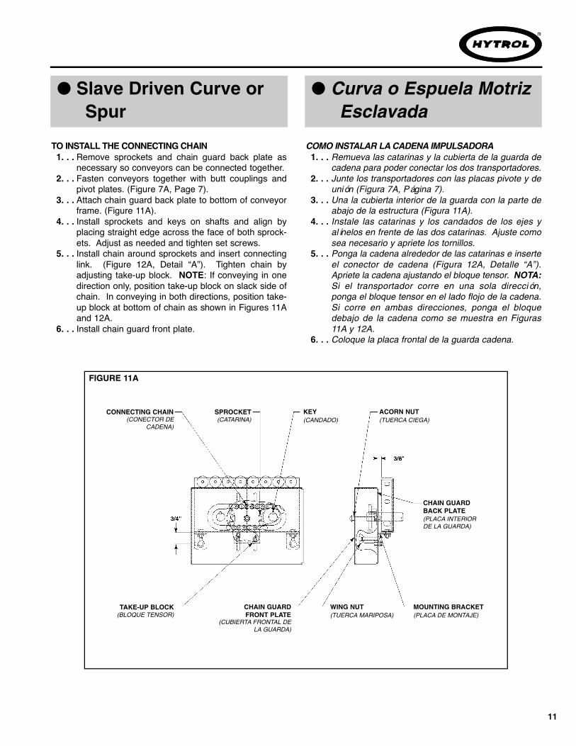
Remueva las catarinas y la cubierta de la guarda decadena para poder conectar los dos transportadores.Junte los transportadores con las placas pivote y deunión (Figura 7A, Página 7).Una la cubierta interior de la guarda con la parte deabajo de la estructura (Figura 11A).Instale las catarinas y los candados de los ejes yalínelos en frente de las dos catarinas. Ajuste comosea necesario y apriete los tornillos.Ponga la cadena alrededor de las catarinas e inserteel conector de cadena (Figura 12A, Detalle “A”).Apriete la cadena ajustando el bloque tensor. NOTA:Si el transportador corre en una sola dirección,ponga el bloque tensor en el lado flojo de la cadena.Si corre en ambas direcciones, ponga el bloquedebajo de la cadena como se muestra en Figuras11A y 12A.Coloque la placa frontal de la guarda cadena.
Remove sprockets and chain guard back plate asnecessary so conveyors can be connected together.Fasten conveyors together with butt couplings andpivot plates. (Figure 7A, Page 7).Attach chain guard back plate to bottom of conveyorframe. (Figure 11A).Install sprockets and keys on shafts and align byplacing straight edge across the face of both sprock-ets. Adjust as needed and tighten set screws.Install chain around sprockets and insert connectinglink. (Figure 12A, Detail “A”). Tighten chain byadjusting take-up block. NOTE: If conveying in onedirection only, position take-up block on slack side ofchain. In conveying in both directions, position take-up block at bottom of chain as shown in Figures 11Aand 12A.Install chain guard front plate.
1. . .
2. . .
3. . .
4. . .
5. . .
6. . .
TO INSTA L L THE CONNECTING CHAIN COMO INSTALAR LA C A D E N A I M P U L S A D O R A
● Slave Driven Curve orSpur
● Curva o Espuela Motriz Esclavada
FIGURE 11A
CHAIN GUARDFRONT PLATE
(CUBIERTA FRONTAL DELA GUARDA)
KEY(CANDADO)
ACORN NUT(TUERCA CIEGA)
CONNECTING CHAIN(CONECTOR DE
CADENA)
WING NUT(TUERCA MARIPOSA)
MOUNTING BRACKET(PLACA DE MONTAJE)
TAKE-UP BLOCK(BLOQUE TENSOR)
CHAIN GUARDBACK PLATE(PLACA INTERIORDE LA GUARDA)
SPROCKET(CATARINA)
1. . .
2. . .
3. . .
4. . .
5. . .
6. . .

12
DETAIL “A”
TREAD ROLLERS
CONNECTING CHAIN
(RODILLOS)
(CADENA IMPULSADORA)
● Pressure Adjustment ● Ajuste de PresiónMODEL “ACC” (Figure 13A)The “ACC” is equipped with suspension angles that supportthe pressure rollers and hold the drive V-belt in contact withthe tread rollers. Knurled nuts allow the conveyor to be fine-ly adjusted for minimum pressure accumulation. To makethis adjustment, follow the steps listed below.
With conveyor running, reduce pressure on all treadrollers to zero by loosening the knurled adjustmentnuts.Place heaviest item to be conveyed on infeed end ofconveyor, Increase pressure under the item by tight-ening the knurled nuts. Apply only enough pressureto barely move the item.As the item moves, continue adjustment ahead ofitem until it moves the entire length of conveyor.Return item to infeed end of unit. It should now travelthe entire length of conveyor. If not, repeat the adjust-ment procedure in the problem area.
MODELO “ACC” (Figura 13A)El Modelo “ACC” viene con ángulos de suspensión quesostienen los rodillos de presión y mantienen la banda-Vmotriz en contacto con los rodillos de transportación. Lastuercas de ajuste permiten que el transportador se ajusteadecuadamente para una acumulación mínima. Para hacereste ajuste, siga los siguientes pasos.
Con el transportador en movimiento, reduzca la pre -sión a los rodillos de transportación aflojando las tuer -cas de ajuste.Ponga la caja u objeto más pesado, en el extremo dela carga. Aumente la presión apretando las tuercasde ajuste. Aplique la presión suficiente para que elobjeto se empieze a mover.Mientras el objeto se mueve, continue el ajuste depresión en frente del objeto hasta que recorra todo ellargo del transportador.Regrese el objeto al extremo de carga. Este deberecorrer todo el transportador. Si no, repita el ajusteen el área del problema.
1. . .
2. . .
3. . .
4. . .
1. . .
2. . .
3. . .
4. . .
FIGURE 12A
DRIVE UNIT SHEAVE(POLEA ACANALADA DE
LA UNIDAD MOTRIZ)
CHAIN GUARD FRONT PLATE(PLACA INTERIOR DE LA GUARDA)
SLAVED UNIT SHEAVE(POLEA ACANALADA DELA UNIDAD ESCLAVADA)
DRIVE V-BELT(BANDA-V)
TAKE-UP BOLCK(BLOQUE TENSOR)
SPROCKETS(CATARINAS)
CHAIN GUARD BACK PLATE(CUBIERTA INTERIOR DE LA GUARDA)

13
MODEL “LRC” , “LRS”, & “LRSS” (Figure 13B)Curves and spurs have snub sheaves that hold the drive V-belt in contact with its tread rollers. Adjustments are madeby moving the snub sheaves up or down in the slotted con-veyor channel.When making adjustments, apply only enough force tomove the heaviest item to be conveyed.
TREADROLLER
DRIVING V-BELT
TREAD ROLLERS
SNUB SHEAVE
SHEAVEADJUSTMENT BOLT
R I G H T WRONG SNUBBEDTOO MUCH
PRESSUREROLLER
KNURLED A D J U S T-MENT NUT
DRIVE V-BELT SPRING
SUSPENSIONANGLE
MODELOS “LRC” , “LRS”, & “LRSS” (Figura 13B)Curvas y espuelas tienen poleas de retorno que mantienenla banda-V motriz en contacto con sus rodillos de trans -portación. Los ajustes se hacen moviendo las poleas verti -calmente en el canal ranurado del transportador.Para hacer ajustes, aplique solamente la presión suficientepara mover el objeto más pesado.
(RODILLOS)
(BANDA-VMOTRIZ)
(RESORTE)
(TUERCA DE AJUSTE)(ANGULO DESUSPENSION)
(RODILLO DEPRESION)
(BANDA-V MOTRIZ)
(RODILLOS)
(POLEA DE RETORNO)
(TORNILLO DE RETORNO)
(CORRECTO)( I N C O R R E C TO, DEMASI -
ADO A P R E TA D O )
NOTE: Do not apply more pressure than necessary tomove the heaviest package.
NOTA: No aplique más presión de la que sea necesariapara mover el objeto más pesado.
PRECAUCION!Apretar la banda demasiado puede causar que eltransportador se detenga.
CAUTION!Snubbing the belt too much can cause the conveyor tostall.
FIGURE 13BFIGURE 13A

WARNING!Electrical controls shall be installed and wired by aqualified electrician. Wiring information for the motorand controls are furnished by the equipment manufac-turer.
CONTROLS
Electrical Code: All motor controls and wiring shall conformto the National Electrical Code (Article 670 or other applica-ble articles) as published by the National Fire ProtectionAssociation and as approved by the American StandardsInstitute, Inc.
CONTROL STATIONS
A) Control stations should be so arranged and located thatthe operation of the equipment is visible from them, andshall be clearly marked or labeled to indicate the functioncontrolled.
B) A conveyor which would cause injury when started shallnot be started until employees in the area are alerted by asignal or by a designated person that the conveyor is aboutto start.
When a conveyor would cause injury when started andis automatically controlled or must be controlled from aremote location, an audible device shall be provided whichcan be clearly heard at all points along the conveyor wherepersonnel may be present. The warning device shall beactuated by the controller device starting the conveyor andshall continue for a required period of time before the con-veyor starts. A flashing light or similar visual warning may beused in conjunction with or in place of the audible device ifmore effective in particular circumstances.
Where system function would be seriously hindered oradversely affected by the required time delay or where theintent of the warning may be misinterpreted (i.e., a workarea with many different conveyors and allied devices),clear, concise, and legible warning shall be provided. Thewarning shall indicate that conveyors and allied equipmentmay be started at any time, that danger exists, and that per-sonnel must keep clear. The warnings shall be providedalong the conveyor at areas not guarded by position or loca-tion.
C) Remotely and automatically controlled conveyors, andconveyors where operator stations are not manned or arebeyond voice and visual contact from drive areas, loadingareas, transfer points, and other potentially hazardous loca-tions on the conveyor path not guarded by location, position,or guards, shall be furnished with emergency stop buttons,pull cords, limit switches, or similar emergency stopdevices.
ADVERTENCIA!Los controles eléctricos deben ser conectados e i nsta -lados por un electricista calificado. La información sobreel cableado del motor y los controles será proporcionadapor el fabricante del equipo.
C O N T R O L E S
Código Eléctrico: Todos los controles del motor y lasconexiones deben ajustarse al National Electrical Code(Artículo 670 u otros artículos aplicables) como fue publicadopor la National Fire Protection Association y aprobado por elAmerican Standards Institute, Inc.
E S TACIONES DE CONTROL
A) Las estaciones de control deberán estar arregladas y ubi -cadas de tal forma que el funcionamiento del equipo sea vi-sible y deberán estar claramente marcadas o señaladas paraindicar la función controlada.
B) Un transportador que pueda causar lesiones cuando espuesto en marcha, no deberá ponerse a funcionar hasta quelos trabajadores en el área sean alertados por una señal o poruna persona designada que indique que el transportador estáa punto de arrancar.Cuando un transportador pueda causar lesiones al arrancar yes automáticamente controlado, o tiene que ser controladodesde una ubicación lejana, se deberá proporcionar un dispo-sitivo sonoro el cual pueda ser escuchado claramente entodos los puntos a lo largo del transportador donde el person -al pueda estar presente. El dispositivo de advertencia deberáser activado por el dispositivo de arranque del transportador, ydeberá continuar sonando por un determinado periodo detiempo antes de que el transportador empiece a funcionar.Una luz intermitente o una advertencia visual similar puede serutilizada con o en lugar del dispositivo sonoro si es más efec -tivo en circunstancias particulares.Donde el funcionamiento del sistema pudiera ser seriamenteobstruido o adversamente afectado por el tiempo de retardorequerido, o donde el intento de advertencia pueda ser malinterpretado (ej., un área de trabajo con diversas líneas detransportadores y los dispositivos de advertencia relaciona -dos), advertencias claras, concisas y legibles deberán ser pro -porcionadas. Las advertencias deberán indicar que los trans -portadores y los equipos relacionados pueden ser puestos enmarcha en cualquier momento, que existe un peligro y que elpersonal debe mantenerse alejado. Estas advertencias debenser proporcionadas a lo largo del transportador en áreas queno sean protegidas por la posición o la ubicación.
C ) Los transportadores controlados automáticamente o desdeestaciones lejanas, y los transportadores donde las estacionesde funcionamiento no estén controladas por una persona, o
14
● Electrical Equipment ● Equipo Eléctrico

15
All such emergency stop devices shall be easily identifi-able in the immediate vicinity of such locations unlessguarded by location, position, or guards. Where the design,function, and operation of such conveyor clearly is not haz-ardous to personnel, an emergency stop device is notrequired.
The emergency stop device shall act directly on the con-trol of the conveyor concerned and shall not depend on thestopping of any other equipment. The emergency stopdevices shall be installed so that they cannot be overriddenfrom other locations.
D) Inactive and unused actuators, controllers, and wiringshould be removed from control stations and panel boards,together with obsolete diagrams, indicators, control labels,and other material which serve to confuse the operator.
SAFETY DEVICES
A) All safety devices, including wiring of electrical safetydevices, shall be arranged to operate in a “Fail-Safe” man-ner, that is, if power failure or failure of the device itselfwould occur, a hazardous condition must not result.
B) Emergency Stops and Restarts. Conveyor controls shallbe so arranged that, in case of emergency stop, manualreset or start at the location where the emergency stop wasinitiated, shall be required of the conveyor(s) and associat-ed equipment to resume operation.
C) Before restarting a conveyor which has been stoppedbecause of an emergency, an inspection of the conveyorshall be made and the cause of the stoppage determined.The starting device shall be locked out before any attemptis made to remove the cause of stoppage, unless operationis necessary to determine the cause or to safely remove thestoppage.
Refer to ANSI Z244.1-1982, American National Standard forPersonnel Protection – Lockout/Tagout of Energy Sources– Minimum Safety Requirements and OSHA StandardNumber 29 CFR 1910.147 “The Control of Hazardous Ener-gy (Lockout/Tagout).”
estén mas allá del alcance de la voz y del contacto visual delas áreas de conducción, áreas de carga, puntos de transfe-rencia y otros sitios potencialmente peligrosos localizadosen la trayectoria del transportador que no tenga protección,ya sea dada por posición, ubicación, o guardas, deberán serequipados con interruptores de parada de emergencia, cor -dones de parada de emergencia, interruptores de límite odispositivos similares para paradas de emergencia.Todos estos dispositivos de parada de emergencia deberánser fácilmente identificables en las cercanías inmediatas aestos puntos potencialmente peligrosos, a no ser que esténprotegidos dada su ubicación, posición o protegidos conguardas. Donde el diseño, el funcionamiento, y la operaciónde tales transportadores no represente un claro peligro parael personal, un dispositivo de parada de emergencia no esrequerido. El dispositivo de parada de emergencia deberá actuar direc -tamente en el control del transportador concerniente y nodeberá depender de la parada de cualquier otro equipo. Losdispositivos de parada de emergencia deberán ser instala -dos de tal forma que no puedan ser anulados desde otrasl o c a l i d a d e s .
D) Los dispositivos, controles inactivos y no usados, ycables, deberán ser removidos de las estaciones de controly de los tableros de mando, junto con los diagramas, indi -cadores, etiquetas de control y otros materiales obsoletos,los cuales se prestan para confundir al operador.
DISPOSITIVOS DE SEGURIDAD
A) Todos los dispositivos de seguridad, incluyendo laconexión de dispositivos eléctricos, deben ser dispuestospara operar en una manera de “autoprotección”; es decir, sise presenta una pérdida de corriente o un fallo en el mismodispositivo, no debe presentarse una situación peligrosa.
B) Paradas de Emergencia y Reactivadores. Los controlesdel transportador deberán estar dispuestos de tal maneraque, en caso de una parada de emergencia, se requerirá unactivador o arrancador manual en la ubicación donde laparada de emergencia se presentó para reanudar laoperación del transportador o transportadores y el equipoa s o c i a d o .
C) Antes de volver a poner en marcha un transportador quehaya sido detenido por una emergencia, debe revisarse ydeterminar la causa de la parada. El dispositivo de arranquedeberá ser asegurado antes de intentar corregir o remover lacausa que originó la parada, a no ser que la operación deltransportador sea necesaria para determinar la causa o pararemover sin peligro la causa de la parada.
Refiérase a ANSI Z244.1-1982, American National Standardfor Personnel Protection - Lockout/Tagout of Energy Sources- Minimum Safety Requirements and OSHA S t a n d a r dNumber 29 CFR 1910.147 “The Control of HazardousEnergy (Lockout/Ta g o u t ) . ”

16
O P E R AT I O N
A ) Only trained employees shall be permitted to operate conveyors.Training shall include instruction in operation under normal conditionsand emergency situations.
B ) Where employee safety is dependent upon stopping and/or startingdevices, they shall be kept free of obstructions to permit ready access.
C ) The area around loading and unloading points shall be kept clear ofobstructions which could endanger personnel.
D ) No person shall ride the load-carrying element of a conveyor underany circumstances unless that person is specifically authorized by theowner or employer to do so. Under those circumstances, such employ-ee shall only ride a conveyor which incorporates within its supportingstructure, platforms or control stations specifically designed for carryingpersonnel. Under no circumstances shall any person ride on any ele-ment of a vertical conveyor. Owners of conveyors should affix warningdevices to the conveyor reading Do Not Ride Conveyor.
E) Personnel working on or near a conveyor shall be instructed as to thelocation and operation of pertinent stopping devices.
F ) A conveyor shall be used to transport only material it is capable ofhandling safely.
G ) Under no circumstances shall the safety characteristics of the con-veyor be altered if such alterations would endanger personnel.
H ) Routine inspections and preventive and corrective maintenance pro-grams shall be conducted to insure that all safety features and devicesare retained and function properly.
I ) Personnel should be alerted to the potential hazard of entanglement inconveyors caused by items such as long hair, loose clothing, and jewel-ry.
J )As a general rule, conveyors should not be cleaned while in operation.Where proper cleaning requires the conveyor to be in motion and a haz-ard exists, personnel should be made aware of the associated hazard.
O P E R A C I O N
A) Solo se debe permitir operar los transportadores a empleados entre -nados. El entrenamiento debe incluir instrucciones de operación bajocondiciones normales y en situaciones de emergencia.
B ) Donde la seguridad de los trabajadores dependa de dispositivos deparada y/o arranque, éstos deberán mantenerse libres de obstruccionespara permitir un acceso rápido.
C ) El área alrededor de los puntos de carga y descarga debe mantenerselibre de obstrucciones, las cuales podrían poner en peligro al personal.
D ) Ninguna persona debe montarse en la parte de conducción de cargade un transportador bajo ninguna circunstancia al menos que esta per -sona esté específicamente autorizada por el dueño o por el empleadoencargado. Bajo estas circunstancias, el empleado deberá montarsesolamente en un transportador que tenga incorporado dentro de suestructura, plataformas o estaciones de control especialmente diseñadaspara el traslado de personal. Bajo ninguna circunstancia, persona algunadebe subirse a cualquier parte de un transportador vertical. Los dueñosde los transportadores deben añadir señales de advertencia al trans -portador con el texto: “No Montarse en el Tr a n s p o r t a d o r ” .
E ) El personal que esté trabajando en, o cerca al transportador, deberáser instruido en cuanto a la ubicación y operación de los dispositivos per -tinentes de parada.
F ) Un transportador deberá ser usado para transportar solo el productoque es capaz de manejarlo seguramente.
G ) Bajo ninguna circunstancia deberán ser alteradas las característicasde seguridad de un transportador, si tales alteraciones pudieran poner enpeligro al personal.
H) Inspecciones rutinarias deberán llevarse a cabo al igual que progra -mas preventivos y correctivos de mantenimiento, para asegurar quetodos los dispositivos y medidas de seguridad sean conservados en buenestado y funcionen correctamente.
I ) El personal deberá ser avisado de peligros potenciales como enredosen transportadores causados por materiales como pelo largo, ropa sueltao joyas.
J ) Como regla general, los transportadores no deberán limpiarse mien -tras estén en funcionamiento. Cuando se requiera limpiar el transporta -dor estando en movimiento y exista posibilidad de peligro, el personaldeberá ser avisado de este posible riesgo.
● Conveyor Start-UpBefore conveyor is turned on, check for foreign objects that may havebeen left inside conveyor during installation. These objects could causeserious damage during start-up.After conveyor has been turned on and is operating, check motors,reducers, and moving parts to make sure they are working freely.
●Arranque del Transportador
PRECAUCION!Debido a la cantidad de partes en movimiento en eltransportador, todo el personal en el área del trans -portador necesita ser advertido de que este está apunto de ponerse en marcha.
Antes de poner en marcha el transportador, revise si hay objetos ajenosque puedan haber sido dejados dentro del transportador durante la insta -lación. Estos objetos pueden causar serios daños en el arranque. Después de que el transportador arranque y esté operando, verifique losmotores, reductores y partes en movimiento para estar seguro de queestán trabajando libremente.
CAUTION!Because of the many moving parts on the conveyor, allpersonnel in the area of the conveyor need to bewarned that the conveyor is about to be started.
● Operation Safety Precautions ●Medidas de Seguridad en la Operación

17
M A I N T E N A N C E M A N T E N I M I E N TO
A ) Maintenance, such as lubrication and adjustments, shall be per-formed only by qualified and trained personnel.B ) It is Important that a maintenance program be established to insurethat all conveyor components are maintained in a condition which does notconstitute a hazard to personnel.C ) When a conveyor is stopped for maintenance purposes, startingdevices or powered accessories shall be locked or tagged out in accor-dance with a formalized procedure designed to protect all person orgroups involved with the conveyor against an unexpected start.D ) Replace all safety devices and guards before starting equipment fornormal operation.E ) Whenever practical, DO NOT lubricate conveyors while they are inmotion. Only trained personnel who are aware of the hazard of the con-veyor in motion shall be allowed to lubricate.
S A F E T Y G U A R D SMaintain all guards and safety devices IN POSITION and IN SAFER E PA I R .
WARNING SIGNSMaintain all warning signs in a legible condition and obey all warnings. SeePage 3 of this manual for examples of warning signs.
A ) El mantenimiento, tal como lubricación y ajustes, debe ser realizado sola -mente por personal calificado y entrenado.B ) Es importante que se establezca un programa de mante- nimiento, paraasegurar que todos los componentes del transportador sean mantenidos encondiciones que no constituyan un peligro para el personal.C ) Cuando un transportador esté parado por razones de mante-nimiento,los dispositivos de arranque o accesorios motorizados deberán ser asegu -rados o desconectados conforme a un procedimiento formalizado, dis -eñado para proteger de cualquier arranque inesperado a toda persona ogrupos de personas involucrados con el transportador.D ) Antes de poner en marcha el equipo, vuelva a colocar todos los dispos -itivos de seguridad y las guardas.E ) Siempre que sea práctico, N O lubrique los transportadores mientras seencuentren en movimiento. Solo el personal entrenado, que tengaconocimiento de los peligros del transportador en movimiento, se le permi -tirá lubricarlos de esta manera.
PROTECCIONES DE SEGURIDADMantenga todas las guardas y dispositivos de seguridad EN SU POSICIONy EN BUENAS CONDICIONES.
SEÑALES DE A D V E RT E N C I AMantenga todas las señales de advertencia en condiciones legibles yobedézcalas. Remítase a la página 3 de este manual para ver ejemplos deseñales de advertencia.
● Maintenance SafetyPrecautions
● Medidas de Seguridad en el Mantenimiento
The drive chain is pre-lubricated from the manufacturer by a hot dippingprocess that ensures total lubrication of all components. However, contin-ued proper lubrication will greatly extend the useful life of every drive chain.
Drive Chain lubrication serves several purposes including:• Protecting against wear of the pin-bushing joint• Lubricating chain-sprocket contact surfaces• Preventing rust or corrosion
For normal operating environments, lubricate every 2080 hours of opera-tion or every 6 months, whichever comes first. Lubricate with a good gradeof non-detergent petroleum or synthetic lubricant (i.e., Mobile 1 Synthetic).For best results, always use a brush to generously lubricate the chain. Theproper viscosity of lubricant greatly affects its ability to flow into the internalareas of the chain. Refer to the table below for the proper viscosity of lubri-cant for your application.
The drive chain’s lubrication requirement is greatly affected by the operat-ing conditions. For harsh conditions such as damp environments, dustyenvironments, excessive speeds, or elevated temperatures, it is best tolubricate more frequently. It may be best, under these conditions, to devel-op a custom lubrication schedule for your specific application. A customlubrication schedule may be developed by inspecting the drive chain onregular time intervals for sufficient lubrication. Once the time interval isdetermined at which the chain is not sufficiently lubricated, lubricate it andschedule the future lubrication intervals accordingly.
La cadena motriz ha sido pre-lubricada por el fabricante mediante unproceso de sumersión caliente que asegura una lubricación total detodos sus componentes. Sin embargo, una lubricación apropiada ycontinua extenderá su vida útil considerablemente.
La lubricación de la cadena motriz cumple varios propósitos:• Proteger contra el desgaste de la unión de pines
de la cadena • Lubricar las superficies de contacto entre la cadena
y la catarina• Prevenir la oxidación o corrosión.
En operaciones bajo condiciones ambientales normales, lubrique cada2080 horas de operación o cada 6 meses, lo que ocurra primero.Lubrique con un lubricante sintético (ej. Mobile 1 sintético) o basado enpetroleo no-detergente de buen grado. Para mejores resultados, siem -pre utilice una brocha para lubricar la cadena generosamente. La vis -cosidad apropiada del lubricante afecta enormente el fluido del mismohacia las áreas internas de la cadena. Refiérase a la siguiente tablapara consultar la viscosidad de lubricante adecuada para su apli -cación.
El requerimiento de lubricación de la cadena motriz se vé afectadoconsiderablemente por las condiciones de operación. En condicionesdifíciles tales como: ambientes húmedos, ambientes con polvo, veloci -dades excesivas, o temperaturas elevadas, se recomienda lubricar lacadena con más frecuencia. Lo mejor sería que bajo estas condicionesse establezca un programa de lubricación específico para su apli -cación. Este programa específico puede desarrollarse mediante lainspección de la lubricación suficiente de la cadena motriz en interval -os regulares de tiempo. Una vez se ha determinado el intervalo en elcual la cadena no se encuentra suficientemente lubricada, lubríquela yprograme los siguientes intervalos de acuerdo al intervalo anterior.
● Lubrication ● Lubricación
Ambient Temperature SAE ISODegrees F
20-40 20 46 or 6840-100 30 100100-120 40 150 Temperatura A m b i e n t e S A E I S O
(Grados Fº) (Grados Cº)2 0 - 4 0 -07 – 04 2 0 46 o 684 0 - 1 0 0 04 – 38 3 0 1 0 01 0 0 - 1 2 0 38 – 49 4 0 1 5 0

18
MODEL “ACC”1. . . Check length of section in which belt is to be replaced.2. . . Determine if a “long” or “short” belt is needed. (Figure
19A).3. . . See Parts List for correct replacement number, Pages
26 & 27. See NOTES in page 19.
TO REPLACE BELT1. . . Using knurled nuts, lower belt away from tread rollers
in section belt is being replaced.2. . . Remove five tread rollers from each end of section.3. . . Remove all pressure rollers.4. . . Replace belt and all rollers.5. . . Adjust accumulating pressure per instructions on
Page 12.
MODEL “LRC”, “LRS” , & “LRSS”1. . . Check Overall Frame Width (OAW) (Figure 19B).2. . . Determine degree of curve or spur.3. . . See respective Parts List for correct replacement num-
ber, Pages 28 thru 42. See NOTES in page 19.
TO REPLACE BELT1. . . Note how old belt is installed.2. . . Remove all tread rollers.3. . . Replace belt and all rollers.4. . . Adjust belt tension per instructions on Page 20.
MODELO “ACC”1. . . Revise el largo de la sección en la que se repone la
banda.2. . . Determine si se necesita una banda larga o corta
(Figura 19A).3. . . Vea en la Lista de Partes el número correcto de la
refacción, páginas 26 y 27 Vea las Notas página 19.
PARA REEMPLAZAR LA BANDA1. . . Usando las tuercas de ajuste, baje la banda de los
rodillos de transportación en la sección donde serepone la banda.
2. . . Remueva los cinco rodillos de transportación enambos lados de la sección.
3. . . Remueva todos los rodillos de presión.4. . . Reemplace la banda y coloque todos los rodillos.5. . . Ajuste la presión de acumulación según las instruc -
ciones en Página 12
MODELO “LRC”, “LRS” , & “LRSS”1. . . Revise el Ancho Total del Marco (OAW) (Figura 19B).2. . . Determine el ángulo de la curva o espuela.3. . . Vea en la Lista de Partes respectiva el número cor -
recto de la refacción, Páginas 28 a la 42. Vea lasNotas en la página 19.
PARA REEMPLAZAR LA BANDA1. . . Observe como está puesta la banda.2. . . Remueva todos los rodillos de transportación.3. . . Reemplace la banda y coloque los rodillos.4. . . Ajuste la tensión de la banda segun las instrucciones
en Página 20.
● Belt Replacement ● Reemplazo de la Banda
PRECAUCION!Durante la instalación no use herramientas comodesarmadores, llaves inglesas, etc., porque sepueden dañar las bandas-V.
CAUTION!During installation, do not use tools such as screw-drivers, wrenches, etc., or damage to the V-belts couldoccur.

19
OAW
LONG BELT
PRESSURE ROLLERS DOUBLE GROOVE SHEAVE
SECTION LENGTH(4’, 5’, 6’, 7-1/2’, 8’, OR 10’)
SHORT BELT
TAKE-UP SHEAVETAKE-UP BRACKET
SECTION LENGTH(4’, 5’, 6’, 7-1/2’, 8’, OR 10’)
(BANDA LARGA)
(POLEA DE DOBLE RANURA)
(LARGO DE LA SECCION)
(RODILLOS DE PRESION)
(BANDA CORTA)
(LARGO DE LA SECCION)
(POLEA TENSORA)(SOPORTE TENSOR)
NOTE: Special length V-belts are used on the “ACC” &“LRSS” conveyors. It is recommended that replacementbe obtained from HYTROL.The Models “LRC” & “LRS” use standard “B” sectionindustrial grade V-belts (Non-Glass Core). these beltsmay either be purchased from HYTROL or local suppli-ers.
NOTA: Longitudes especiales de bandas-V son usadasen los transportadores “ACC” & “LRSS”. Se recomien -da obtener el repuesto en HYTROL. Los Modelos “LRC” & “LRS” usan bandas-V tipo indus -trial de sección “B” estándar (Núcleo Sin-Vidrio). Estasbandas pueden comprarse en HYTROL o con dis -tribuidores locales.
FIGURE 19A
FIGURE 19B
20
JAM NUT
TIGHTEN
LOOSEN
BELT
TAKE-UP SCREW
SHEAVE
SHEAVE MOUNTING BOLT TA K E - U P B R A C K E T
DRIVINGBELT
IDLERSHEAVES
TAKE-UPSCREW
TAKE-UPSHEAVE
(TORNILLOTENSOR)
(CONTRATUERCA)
(APRETAR)
(AFLOJAR)
(POLEAS DERETORNO)
(BANDAMOTRIZ)
(POLEATENSORA)
(BANDA)
(POLEA DE BANDA-V)
(TORNILLO TENSOR)
(TORNILLO DE MONTAJEDE LA POLEAS)
(SOPORTE TENSOR)
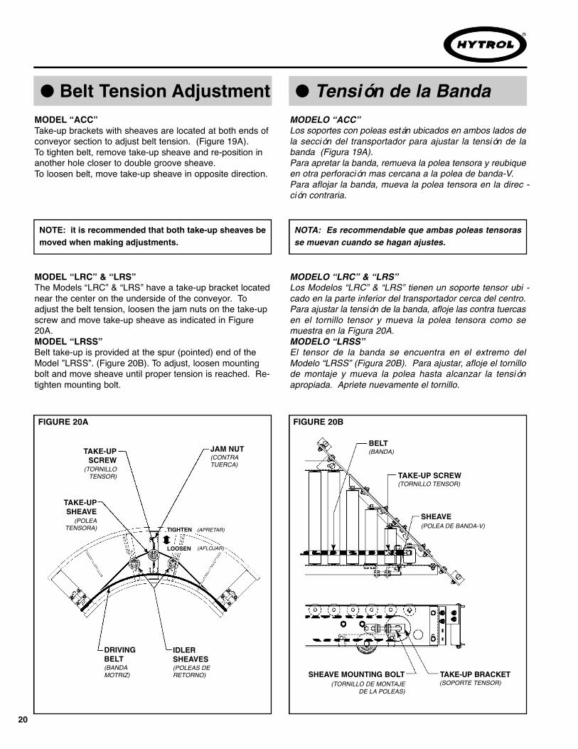
MODEL “LRC” & “LRS”The Models “LRC” & “LRS” have a take-up bracket locatednear the center on the underside of the conveyor. Toadjust the belt tension, loosen the jam nuts on the take-upscrew and move take-up sheave as indicated in Figure20A.MODEL “LRSS”Belt take-up is provided at the spur (pointed) end of theModel ”LRSS”. (Figure 20B). To adjust, loosen mountingbolt and move sheave until proper tension is reached. Re-tighten mounting bolt.
MODELO “LRC” & “LRS”Los Modelos “LRC” & “LRS” tienen un soporte tensor ubi -cado en la parte inferior del transportador cerca del centro.Para ajustar la tensión de la banda, afloje las contra tuercasen el tornillo tensor y mueva la polea tensora como semuestra en la Figura 20A.MODELO “LRSS”El tensor de la banda se encuentra en el extremo delModelo “LRSS” (Figura 20B). Para ajustar, afloje el tornillode montaje y mueva la polea hasta alcanzar la tensiónapropiada. Apriete nuevamente el tornillo.
MODEL “ACC”Take-up brackets with sheaves are located at both ends ofconveyor section to adjust belt tension. (Figure 19A).To tighten belt, remove take-up sheave and re-position inanother hole closer to double groove sheave.To loosen belt, move take-up sheave in opposite direction.
MODELO “ACC”Los soportes con poleas están ubicados en ambos lados dela sección del transportador para ajustar la tensión de labanda (Figura 19A).Para apretar la banda, remueva la polea tensora y reubiqueen otra perforación mas cercana a la polea de banda-V.Para aflojar la banda, mueva la polea tensora en la direc -ción contraria.
● Belt Tension Adjustment ● Tensión de la Banda
NOTE: it is recommended that both take-up sheaves bemoved when making adjustments.
NOTA: Es recommendable que ambas poleas tensorasse muevan cuando se hagan ajustes.
FIGURE 20A FIGURE 20B

21
CAUTION!Never remove chainguards while the con-veyor is running.Always replace guardsafter adjustments aremade.
CHAIN TOO TIGHT(REQUIRES EXTRA POWER)
CHAIN TOO LOOSE
CORRECT SLACKAPPROX. 1/4” OR
2% OF SPROCKET CENTERS
SPROCKET CENTERS
The drive chain and sprockets should be checked periodi-cally for proper tension and alignment. Improper adjustmentwill cause extensive wear to the drive components.
TO MAKE ADJUSTMENTSRemove chain guard.Check sprocket alignment by placing a straightedge across the face of both sprockets (Figure 21A).Loosen set screws and adjust as needed. Re-tightenset screws.To adjust chain tension, loosen bolts that fasten motorbase to mounting angles, both sides of the conveyor.Tighten take-up bolts until desired chain tension isreached. (Figures 21B & 21C). Re-tighten mountingbolts.Lubricate chain per lubrication instructions.Replace chain guard so that it does not interfere withdrive.
1. . .2. . .
3. . .
4. . .5. . .
MOTOR/REDUC-ER DRIVE
DRIVEPULLEY
MOUNTINGBOLTS
PRECAUCION! Nunca remueva laguarda de cadenamientras el transporta -dor esté en fun -c i o n a m i e n t o . S i e m p r evuelva a colocar lasguardas después deque se hayan hecholos ajustes .
La cadena motriz y las catarinas deberán ser revisadasperiódicamente para mantener su apropiada tensión yalineación. Ajustes incorrectos causarán un desgaste exce -sivo a los componentes de la transmisión.
PARA HACER AJUSTES
REDUCERSPROCKET
GEAR REDUCER
DRIVE SHAFTSPROCKET
SET SCREWS
STRAIGHT EDGE(NIVEL)
(CATARINA DELREDUCTOR)
(TORNILLOS CANDADOS)(EJE DE
TRANSMISION)
(REDUCTOR)
(POLEAMOTRIZ)
(TORNILLOS DEMONTAJE)
(MOTOR/REDUCTORMOTRIZ)
(CADENA DEMASIADO TENSA[REQUIERE MAS POTENCIA])
(CADENA DEMASIA -DO FLOJA)
(TENSION CORRECTA) (1/4” O 2% DE CENTROS DECATARINAS APROX.)
(CENTROS DECATARINAS)
DRIVE PULLEYSPROCKET
(CATARINA DE LAPOLEA MOTRIZ)
REDUCERSPROCKET(CATARINA DELREDUCTOR)
TAKE-UPBOLTS(TORNILLOSTENSORES)
MOTOR BASE PLATE(PLACA DEL MOTOR
BASE)
Remueva la guarda cadena.Verifique la alineación de las catarinas colocando unnivel sobre las caras de ambas catarinas. (Figura21A). Afloje los tornillos candados y ajuste tantocomo sea necesario. Apriete los tornillos candados.Para ajustar la tensión de la cadena, afloje los tornil -los que aseguran la base del motor a los ángulos demontaje, a ambos lados del transportador. Apriete lostornillos tensores hasta obtener la tensión correcta dela cadena (Figuras 21B & 21C). Apriete los tornillosde montaje.Lubrique la cadena de acuerdo a las instrucciones delubricación.Coloque la guarda de cadena para que no interfieracon la transmisión.
1. . .2. . .
3. . .
4. . .
5. . .
● Drive Chain Alignment and Tension
● Alineación y Tensión dela Cadena Motriz
FIGURE 21A
FIGURE 21CFIGURE 21B

● Trouble Shooting
22
The following charts list possible problems that may occur in the operation of a powered conveyor.
TROUBLE SHOOTING DRIVES
TROUBLE CAUSE SOLUTIONConveyor will not start or motor quits fre-quently.
Drive chain and sprockets wear excessively.
Loud popping or grinding noise.
Motor or reducer overheating.
1) Motor is overloaded.2) Motor is drawing too much current.
1) Lack of lubrication on chain causing chainstretch which creates improper chain tosprocket mesh.
2) Sprockets are out of alignment.3) Loose chain.
1) Defective bearing.2) Loose set screws in bearing.3) Loose drive chain.
1) Conveyor is overloaded.
2) Low voltage to motor.3) Low lubricant level in reducer.
1) Check for overloading of conveyor.2) Check heater or circuit breaker and change if necessary.
1) Replace chain and sprockets. Provide adequate lubrication.NOTE: If problem reoccurs, a chain take-up may be required.
2) Align sprockets. See “Drive Chain Alignment and Tension”.3) Tighten chain.
1) Replace bearing.2) Tighten set screw.3) Tighten chain.
1) Check capacity of conveyor and reduce load to recommended level.
2) Have electrician check and correct as necessary.3) Relubricate per manufacturer’s recommendations. For HYTROL
reducer, refer to separate manual.
TROUBLE SHOOTING DRIVE BELT TRACKING
TROUBLE CAUSE SOLUTION
Belt slips or won’t move, but drive runs.
Belt moving, but tread rollers not turning.
1) Conveyor is overloaded 2) Belt too loose.
3) Too much pressure against belt frompressure rollers
1) Not enough pressure against belt from pressure rollers.
2) Bolt in the pressure roller suspension angle binding will not allow adjustment ofpressure rollers.
3) Missing or broken springs or adjustment nuts.
1) Check capacity of conveyor and reduce load to recommended level.2) Re-position take-up sheaves in hole closer to double groove
sheaves.3) Loosen spring tension on pressure rollers in area of stalled rollers.
See “Minimum Pressure Adjustment” in Operation section of this manual.
1) Tighten spring tension on pressure rollers in area of stalled rollers. See “Minimum Pressure Adjustment” in Operation section of this manual.
2) Loosen bolt and adjust spring tension as required. Check for bursor foreign material behind angles.
3) Replace and re-adjust.

23
● Resolviendo Problemas
Los siguientes cuadros describen posibles problemas que pueden ocurrir en la operación de un transportador motorizado.
RESOLVIENDO PROBLEMAS DE TRANSMISION
PROBLEMA CAUSA SOLUCION
El transportador no arranca o el motor sedetiene frecuentemente.
Desgaste excesivo de la cadena motriz ylas catarinas.
Funcionamiento muy ruidoso.
Motor o reductor recalentado.
1) El motor está sobrecargado.2) El motor pasa demasiada corriente.
1) Falta de lubricación en la cadena causando su extensión lo cual crea una cadena inapropiada.
2) Los catarinas están desalineadas.3) La cadena está floja.
1) Rodamientos defectuosos.2) El tornillo candado está flojo.3) La cadena está floja.
1) Transportador está sobrecargado.
2) Bajo voltaje al motor.3) Bajo nivel de lubricante en reductor.
1) Revise si hay sobrecarga del transportador.2) Revise los circuitos e interruptores de protección y sobrecarga, y cámbielos si es necesario.
1) Reemplaze la cadena y las catarinas. Proporcione una adecuadalubricación. NOTA: Si se presentan problemas, posiblemente serequiere tensionar la cadena.
2) Alinee catarinas. Vea “Alineación y Tensión de Cadena Motriz” .3) Tensione la cadena.
1) Reemplaze los baleros.2) Apriete el tornillo candado.3) Tensione la cadena.
1) Revise la capacidad del transportador y reduzca la carga al nivelrecomendado.
2) Haga un chequeo por un electricista y corrija si es necesario.3) Vuelva a lubricar de acuerdo a las recomendaciones del fabri-
cante. Para el reductor HYTROL, refiérase al manual adjunto.
RESOLVIENDO PROBLEMAS DE ALINEACION DE LA BANDA MOTRIZ
PROBLEMA CAUSA SOLUCION
La banda se desliza o no se mueve pero elmotor corre
La banda corre pero los rodillos no.
1) El transportador está sobrecargado.
2) La banda está floja.
3) Hay demasiada presión contra la banda por los rodillos de presión.
1) No hay suficiente presión contra la bandapor los rodillos de presión.
2) El tornillo en el ángulo de suspensión nodeja que se ajusten los rodillos de presión.
3) Hay resortes o tornillos de ajuste perdidoso rotos.
1) Revise la capacidad del transportador y reduzca la carga al nivel recomendado.
2) Reubique las poleas tensoras en una perforación mascercana a las poleas de doble ranura.
3) Afloje la tensión de la tuerca de ajuste en el área de losrodillos parados. Vea “Ajuste de Presión Mínima” en lasección de Operación de este manual.
1) Apriete las tuercas de ajuste en el área de los rodillosparados. Vea “Ajuste de Presión Mínima” en la sección deOperación de este manual.
2) Afloje el tornillo y ajuste tensión del resorte como sea necesario. Revise si hay material o suciedad detrás de los ángulos.
3) Reemplaze y ajuste nuevamente.

24
The following is a general maintenance checklist whichcovers the major components of your conveyor.
This will be helpful in establishing a standard maintenanceschedule.
La siguiente es una lista de verificación del mantenimientopreventivo la cual cubre principales componentes de su
transportador. Esta será util para establecer un programade mantenimiento estándar.
● Preventive Maintenance Checklist
● Lista de Mantenimiento Preventivo
Check NoiseCheck TemperatureCheck Mounting BoltsCheck NoiseCheck TemperatureCheck Oil Level
Check TensionLubricateCheck for Wear
Check TensionCheck for WearCheck for Sheave AlignmentGeneral Check: All loose bolts, etc., tightened
Check NoiseCheck Mounting Bolts
SCHEDULESUGGESTED ACTIONCOMPONENT
MOTOR
REDUCER
DRIVE CHAIN
STRUCTURAL
V-BELTS
BEARINGS(Pulleys & Rollers)
SPROCKETS
Weekly Monthly Quarterly
Revisar RuidoRevisar la TemperaturaRevisar los Tornillos de MontajeRevisar RuidoRevisar la TemperaturaRevisar el Nivel de Aceite
Revisar RuidoLubricarRevisar el Desgaste
Revisar la TensiónRevisar el DesgasteRevisar la Alineación de la Polea
Revisión General: Tornillos flojos, etc.
Revisar RuidoRevisar los Tornillos de Montaje
HORARIOREMEDIOCOMPONENTE
MOTOR
REDUCTOR
CADENA MOTRIZ
ESTRUCTURAL
BANDAS-V
RODAMIENTOS(Poleas & Rodillos)
CATARINAS
Semanal Mensual Trimestral
Revisar el DesgasteRevisar los Tornillos de Montaje
Check for WearCheck Set Screws & Keys

25
Included in this manual are parts drawings with completereplacement parts lists. Minor fasteners, such as nuts andbolts, are not included.
When ordering replacement parts:
Contact Dealer from whom conveyor was purchasedor nearest HYTROL Distributor.Give Conveyor Model Number and Serial Number orHYTROL Factory Order Number.Give Part Number and complete description from PartsList.Give type of drive. Example—8” End Drive, 8” CenterDrive, etc.If you are in a breakdown situation, tell us.
1. . .
2. . .
3. . .
4. . .
5. . .
Incluido en este manual hay dibujos de las partes con lis -tas completas de las refacciones. Aseguradores menores,como tornillos y tuercas no están incluidos.
Para ordenar partes de repuesto:
Número de Serie HYTROL(Localizado cerca de laUnidad Motriz en los modelos motorizados).
● How to Order Replacement Parts
● Como Ordenar Partes de Repuesto
Contacte el vendedor que le vendió el transportador oel distribuidor de Hytrol más cercano.Comunique el Modelo del Transportador y el Númerode Serie o Número de la Orden de Planta.Comunique el Número de las partes y descripcióncompleta de la Lista de Partes.Diga el tipo de motor. Ejemplo—8” Unidad Motriz en elExtremo, 8” Unidad Motriz Central, etc.Si está en una situación crítica, comuníqueseinmediatamente.
1. . .
2. . .
3. . .
4. . .
5. . .
HYTROL Serial Number(Located near Drive onPowered Models).

26
● Model 138-ACC Parts Drawing Dibujo de Partes del Modelo 138-ACC
VIEW “A-A”
SECTION “B-B”
*See Page 46 for Slave Connection
(VEA LA PAGINA 44 PARARETENEDORES DE POLEA)
(VISTA “A-A”)
(SECCION “B-B”)
(*Vea la Página 46 para la Conexión Esclavada)
27
● Model 138-ACC Parts List Lista de Partes del Modelo 138-ACC
See Page 25 for Information on How ToOrder Replacement Parts
Recommended Spare Parts HighlightedIn Gray
Vea la Página 25 para información sobre comoordenar partes de repuesto
Partes de Repuesto Recomendadasse Resaltan en Gris
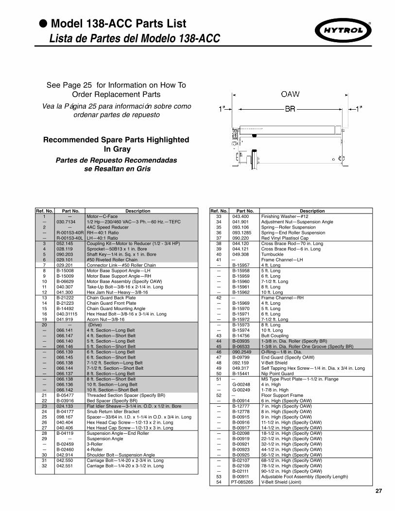
Ref. No. Part No. Description33 043.400 Finishing Washer—#1234 041.901 Adjustment Nut—Suspension Angle35 093.106 Spring—Roller Suspension36 093.1285 Spring—End Roller Suspension37 090.220 Red Vinyl Plastisol Cap38 044.120 Cross Brace Rod—70 in. Long39 044.121 Cross Brace Rod—6 in. Long40 049.308 Turnbuckle41 — Frame Channel—LH— B-15957 4 ft. Long— B-15958 5 ft. Long— B-15959 6 ft. Long— B-15960 7-1/2 ft. Long— B-15961 8 ft. Long— B-15962 10 ft. Long42 — Frame Channel—RH— B-15969 4 ft. Long— B-15970 5 ft. Long— B-15971 6 ft. Long— B-15972 7-1/2 ft. Long— B-15973 8 ft. Long— B-15974 10 ft. Long43 B-14756 Butt Coupling44 B-03935 1-3/8 in. Dia. Roller (Specify BR)45 B-06533 1-3/8 in. Dia. Roller One Groove (Specify BR)46 090.2549 O-Ring—1/8 in. Dia.47 B-09799 End Guard (Specify OAW)48 092.159 V-Belt Shield49 049.317 Self Tapping Hex Screw—1/4 in. Dia. x 3/4 in. Long50 B-15441 Nip Point Guard51 — MS Type Pivot Plate—1-1/2 in. Flange— G-00248 4 in. High— G-00249 1-7/8 in. High52 — Floor Support Frame— B-00914 6 in. High (Specify OAW)— B-12777 7 in. High (Specify OAW)— B-12778 8 in. High (Specify OAW)— B-00915 9 in. High (Specify OAW)— B-00916 11-1/2 in. High (Specify OAW)— B-00917 14-1/2 in. High (Specify OAW)— B-02098 18-1/2 in. High (Specify OAW)— B-00919 22-1/2 in. High (Specify OAW)— B-00921 32-1/2 in. High (Specify OAW)— B-00923 44-1/2 in. High (Specify OAW)— B-00925 56-1/2 in. High (Specify OAW)— B-02107 68-1/2 in. High (Specify OAW)— B-02109 78-1/2 in. High (Specify OAW)— B-02111 90-1/2 in. High (Specify OAW)53 B-00911 Adjustable Foot Assembly (Specify Length)54 PT-085265 V-Belt Shield (Joint)
Ref. No. Part No. Description1 — Motor—C-Face— 030.7134 1/2 Hp—230/460 VAC—3 Ph.—60 Hz.—TEFC2 — 4AC Speed Reducer— R-00153-40R RH—40:1 Ratio— R-00153-40L LH—40:1 Ratio3 052.145 Coupling Kit—Motor to Reducer (1/2 - 3/4 HP)4 028.119 Sprocket—50B13 x 1 in. Bore5 090.203 Shaft Key—1/4 in. Sq. x 1 in. Bore6 029.101 #50 Riveted Roller Chain7 029.201 Connector Link—#50 Roller Chain8 B-15008 Motor Base Support Angle—LH9 B-15009 Motor Base Support Angle—RH10 B-06629 Motor Base Assembly (Specify OAW)11 040.307 Take-Up Bolt—3/8-16 x 2-1/4 in. Long12 041.300 Hex Jam Nut—Heavy—3/8-1613 B-21222 Chain Guard Back Plate14 B-21223 Chain Guard Front Plate15 B-14492 Chain Guard Mounting Angle16 040.31115 Hex Head Bolt—3/8-16 x 3-1/4 in. Long19 041.919 Acorn Nut—3/8-1620 — (Drive)— 066.141 4 ft. Section—Long Belt— 066.147 4 ft. Section—Short Belt— 066.140 5 ft. Section—Long Belt— 066.146 5 ft. Section—Short Belt— 066.139 6 ft. Section—Long Belt— 066.145 6 ft. Section—Short Belt— 066.138 7-1/2 ft. Section—Long Belt— 066.144 7-1/2 ft. Section—Short Belt— 066.137 8 ft. Section—Long Belt— 066.138 8 ft. Section—Short Belt— 066.136 10 ft. Section—Long Belt— 066.142 10 ft. Section—Short Belt21 B-05477 Threaded Section Spacer (Specify BR)22 B-03916 Bed Spacer (Specify BR)23 024.133 Flat Idler Sheave—3-1/4 in. O.D. x 1/2 in. Bore24 B-04177 Snub Return Idler Bracket25 098.167 Spacer—33/64 in. I.D. x 1-1/4 in O.D. x 3/4 in. Long26 040.404 Hex Head Cap Screw—1/2-13 x 2 in. Long27 040.406 Hex Head Cap Screw—1/2-13 x 3 in. Long28 B-04119 Suspension Angle—End Roller29 — Suspension Angle— B-02459 3-Roller— B-02460 4-Roller30 042.914 Shoulder Bolt—Suspension Angle31 042.550 Carriage Bolt—1/4-20 x 2-3/4 in. Long32 042.551 Carriage Bolt—1/4-20 x 3-1/2 in. Long

28
● Model 138-LRC 90° Parts DrawingDibujo de Partes del Modelo 138-LRC 90°
DETAIL “B”
DETAIL “A”
*See Page 46 for Slave Connection
SECTION “C-C”
(VEA LA PAGINA 45 PARARETENEDORES DE POLEAS)
(*Vea la Página 46 para la Conexión Esclavada)
(DETALLE “A”)
(DETALLE “B”)
(SECCION “C-C”)

29
● Model 138-LRC 90° Parts List Lista de Partes del Modelo 138-LRC 90°
See Page 25 for Information on How ToOrder Replacement Parts
Recommended Spare Parts HighlightedIn Gray
Vea la Página 25 para información sobre comoordenar partes de repuesto
Partes de Repuesto Recomendadasse Resaltan en Gris
TAPERED ROLLER CURVE54 — Inside Channel— B-15343 12 in. thru 18 in. OAW— B-15345 24 in. OAW55 — Outside Channel— B-15344 12 in. thru 18 in. OAW (Specify)— B-15346 24 in. OAW56 B-14861 6-1/4 in. Long Tangent Channel57 G-02680 1-3/8 in. Dia. Roller (Specify BR)58 B-15156 1-3/8 in. Dia. Single Groove Roller (Specify BR)59 B-15157 1-3/8 in. Dia. Single Groove Roller (Specify BR)60 B-15371 1-3/8 in. Tapered Roller (Specify BR)61 — Spacer Rod - 5/16 in. Threaded Rod— 044.1142 12 in. OAW— 044.1144 15 in. OAW— 044.1146 18 in. OAW— 044.1148 24 in. OAW
Ref. No. Part No. Description1 — Motor—Foot Mounted— 030.2034 1/2 Hp—230/460 VAC—3 Ph.—60 Hz. — TEFC2 — 4A Speed Reducer— R-00152-20R RH—20:1 Ratio— R-00152-20L LH—20:1 Ratio3 028.1005 Sprocket—Reducer, 50B12 x 1 in. Bore4 028.133 Sprocket—Drive Shaft, 50B14 x 1 in. Bore5 020.104 Sheave—Motor, 3.00 in. O.D. x 5/8 in. Bore6 020.120 Sheave—Reducer, 5.00 in. O.D. x 3/4 in. Bore7 090.202 Shaft Key—3/16 in. Sq. x 1 in. Long8 090.203 Shaft Key—1/4 in. Sq. x 1 in. Bore9 — V-Belt (Motor to Reducer)— 066.105 4L270 (12 in. thru 15 in. OAW)— 066.109 4L310 (18 in. thru 24 in. OAW)10 029.101 #50 Riveted Roller Chain11 029.201 Connector Link—#50 Roller Chain12 — Motor Base Assembly — B-15424 RH Reducer—12 in. thru 18 in. OAW (Specify)— B-15426 RH Reducer—24 in. OAW— B-15425 LH Reducer—12 in. thru 18 in. OAW (Specify)— B-15427 LH Reducer—24 in. OAW (Specify)13 098.1505 Spacer—13/32 in. I.D. x 3/4 in. O.D. x 1-1/8 in. Long14 098.1681 Spacer—13/32 in. I.D. x 1 in. O.D. x 2.304 in. Long15 040.307 Take-Up Bolt—3/8-16 x 2-1/4 in. Long16 041.300 Hex Jam Nut—Heavy—3/8-1617 — Inside V-Belt Guard— B-05275 14 in. Long—RH Reducer—12 in. thru 15 in. OAW— B-05120 16 in. Long—RH Reducer—18 in. thru 24 in. OAW— B-06580 14 in. Long—LH Reducer—12 in. thru 15 in. OAW— B-05558 16 in. Long—LH Reducer—18 in. thru 24 in. OAW18 — Outside V-Belt Guard— B-05274 14 in. Long— 12 in. thru 15 in. OAW— B-05119 16 in. Long— 18 in. thru 24 in. OAW19 — Chain Guard Back Plate— B-15109 RH Reducer— B-15110 LH Reducer20 B-15112 Chain Guard Front Plate21 041.919 Acorn Nut—3/8-1622 — Inside Channel— B-15981 12 in. thru 18 in. OAW— B-14830 24 in. OAW23 — Outside Channel— B-15982 12 in. thru 18 in. OAW (Specify)— B-14831 24 in. OAW 24 — 6-1/4 in. Tangent Channel— B-15983 12 in. thru 18 in. OAW — B-14862 24 in. OAW25 B-14860 Coupling Angle26 B-14756 Butt Coupling27 — V-Belt (Drive)— 066.1315 B-120 (12 in. thru 18 in. OAW)— 066.1325 B-144 (24 in. OAW)28 B-05477 Threaded Section Spacer (Specify BR)29 B-03102 Take-Up Bracket (Specify BR)30 B-03092 Threaded Take-Up Rod (Specify Length)31 B-03091 Sheave Take-Up Angle32 041.201 Hex Jam Nut—1/2-1333 024.1216 V-Idler Sheave—4 in. O.D. x 5/8 in. Bore34 098.1565 Spacer-.687 I.D. x 1 in. O.D. x .25 Long35 041.104 Hex Nut—5/8-11
Ref. No. Part No. Description36 043.104 Flat Washer—5/8 in. I.D.37 043.204 Split Lockwasher—5/8 in. I.D.38 040.5031 Hex Head Cap Screw—5/8-11 x 2-3/4 in. Long39 B-03195 Fixed Idler Bracket (Specify BR)40 024.12431 Sheave—2-1/2 in. O.D. x 3/8 in. Bore with Spacer41 043.101 Flat Washer 5/16 in. I.D.42 049.5285 Flange Locknut—3/8 in.-1643 — One Groove Roller— B-06533 1-3/8 in. Dia. (12 in. thru 18 in. OAW) (Specify BR)— B-06535-176 1.9 in. Dia. Roller (24 in. OAW)44 B-06534 Two Groove Roller (12 in. thru 18 in. OAW) (Specify)45 — Tread Roller— B-03935 1-3/8 in. Dia. (12 in. thru 18 in. OAW) (Specify BR)— G-00486-176 1.9 in. Dia. Roller (24 in. OAW)46 — O-Ring—1/8 in. Dia.— 090.2548 12 in. thru 18 in. OAW— 090.255 24 in. OAW47 B-09799 End Guard (Specify OAW)48 092.159 V-Belt Shield (24 in. OAW Only)49 049.317 Self-Tapping Hex Screw–1/4-20 x 3/4 in. Lg. 24” OAW50 — LS Type Pivot Plate—1-1/8 in. Flange— G-00248 4 in. High— G-00249 1-7/8 in. High51 — Floor Support Frame— B-00914 6 in. High (Specify OAW)— B-12777 7 in. High (Specify OAW)— B-12778 8 in. High (Specify OAW)— B-00915 9 in. High (Specify OAW)— B-00916 11-1/2 in. High (Specify OAW)— B-00917 14-1/2 in. High (Specify OAW)— B-02098 18-1/2 in. High (Specify OAW)— B-00919 22-1/2 in. High (Specify OAW)— B-00921 32-1/2 in. High (Specify OAW)— B-00923 44-1/2 in. High (Specify OAW)— B-00925 56-1/2 in. High (Specify OAW)— B-02107 68-1/2 in. High (Specify OAW)— B-02109 78-1/2 in. High (Specify OAW)— B-02111 90-1/2 in. High (Specify OAW)52 B-00909 Center Support Leg (Specify Length)53 B-00911 Adjustable Foot Assembly (Specify Length)

30
● Model 138-LRC 60° Parts Drawing Dibujo de Partes del Modelo 138-LRC 60°
DETAIL “B”
DETAIL “A”
*See Page 46 for Slave Connection
SECTION “C-C”
(VEA LA PAGINA 45 PARA RETENE -DORES DE POLEA)
(*Vea la Página 46 para la Conexión Esclavada)
(DETALLE “A”)
(DETALLE “B”)
(SECCION “C-C”)

31
● Model 138-LRC 60° Parts List Lista de Partes del Modelo 138-LRC 60°
See Page 25 for Information on How ToOrder Replacement Parts
Recommended Spare Parts HighlightedIn Gray
Vea la Página 25 para información sobre comoordenar partes de repuesto
Partes de Repuesto Recomendadasse Resaltan en Gris
Ref. No. Part No. Description1 — Motor—Foot Mounted— 030.2034 1/2 Hp—230/460 VAC—3 Ph.—60 Hz. — TEFC2 — 4A Speed Reducer— R-00152-20R RH—20:1 Ratio— R-00152-20L LH—20:1 Ratio3 028.1005 Sprocket—Reducer, 50B12 x 1 in. Bore4 028.133 Sprocket—Drive Shaft, 50B14 x 1 in. Bore5 020.104 Sheave—Motor, 3.00 in. O.D. x 5/8 in. Bore6 020.120 Sheave—Reducer, 5.00 in. O.D. x 3/4 in. Bore7 090.202 Shaft Key—3/16 in. Sq. x 1 in. Long8 090.203 Shaft Key—1/4 in. Sq. x 1 in. Bore9 — V-Belt (Motor to Reducer)— 066.105 4L270 (12 in. thru 15 in. OAW)— 066.109 4L310 (18 in. thru 24 in. OAW)10 029.101 #50 Riveted Roller Chain11 029.201 Connector Link—#50 Roller Chain12 — Motor Base Assembly — B-05537 RH Reducer—12 in. thru 15 in. OAW (Specify)— B-05536-018 RH Reducer—18 in. OAW— B-05534-024 RH Reducer—24 in. OAW— B-08543 LH Reducer—12 in. thru 15 in. OAW (Specify)— B-08544-018 LH Reducer—18 in. OAW— B-08545-024 LH Reducer—24 in. OAW13 B-15462 Motor Base Support Angle—LH14 B-15463 Motor Base Support Angle—RH15 040.307 Take-Up Bolt—3/8-16 x 2-1/4 in. Long16 041.300 Hex Jam Nut—Heavy—3/8-1617 098.1505 Spacer—13/32 in. I.D. x 3/4 in. O.D. x 1-1/8 in. Long18 — Inside V-Belt Guard— B-05275 14 in. Long—RH Reducer—12 in. thru 15 in. OAW— B-05120 16 in. Long—RH Reducer—18 in. thru 24 in. OAW— B-06580 14 in. Long—LH Reducer—12 in. thru 15 in. OAW— B-05558 16 in. Long—LH Reducer—18 in. thru 24 in. OAW19 — Outside V-Belt Guard— B-05274 14 in. Long—12 in. thru 15 in. OAW— B-05119 16 in. Long—18 in. thru 24 in. OAW20 — Chain Guard Back Plate— B-15109 RH Reducer— B-15110 LH Reducer21 B-15112 Chain Guard Front Plate22 041.919 Acorn Nut—3/8-1623 — Inside Channel— B-15979 12 in. thru 18 in. OAW— B-14836 24 in. OAW 24 — Outside Channel— B-15980 12 in. thru 18 in. OAW (Specify)— B-14837 24 in. OAW25 — 18 in. Tangent Channel—LH— B-15984-18L 12 in. thru 18 in. OAW— B-14866-18L 24 in. OAW26 — 18 in. Tangent Channel—RH— B-15984-18R 12 in. thru 18 in. OAW— B-14866-18R 24 in. OAW27 B-14860 Coupling Angle28 B-14756 Butt Coupling29 — V-Belt (Drive)— 066.607 B-136 (12 in. thru 18 in. OAW)— 066.1326 B-158 (24 in. OAW)30 B-05477 Threaded Section Spacer—Curve Portion (Specify BR)31 — Threaded Section Spacer—Straight Portion— 040.105 10 in. BR (Bolt)— 040.106 13 in. BR (Bolt)— 040.107 16 in. BR (Bolt)— B-05477-022 22 in. BR (Pipe)32 B-03102 Take-Up Bracket (Specify BR)
Ref. No. Part No. Description33 B-03092 Threaded Take-Up Rod (Specify Length)34 B-03091 Sheave Take-Up Angle35 041.201 Hex Jam Nut—1/2-1336 024.1216 V-Idler Sheave—4 in. O.D. x 5/8 in. Bore37 098.1565 Spacer—.687 I.D. x 1 in. O.D. x .25 Long38 041.104 Hex Nut—5/8-1139 043.104 Flat Washer—5/8 in. I.D.40 043.204 Split Lockwasher—5/8 in. I.D.41 040.5031 Hex Head Cap Screw—5/8-11 x 2-3/4 in. Long42 B-03195 Fixed Idler Bracket (Specify BR)43 024.1226 Flat Idler Sheave 5-1/2 in. O.D. x 5/8 in. Bore44 024.12431 Sheave—2-1/2 in. O.D. x 3/8 in. Bore with Spacer45 043.101 Flat Washer 5/16 in. I.D.46 049.5285 Flange Locknut—3/8 in.-1647 — One Groove Roller— B-06533 1-3/8 in. Dia. (12 in. thru 18 in. OAW) (Specify BR)— B-06535-176 1.9 in. Dia. (24 in. OAW)48 B-06534 Two Groove Roller (12 in. thru 18 in. OAW) (Specify BR)49 — Tread Roller— B-03935 1-3/8 in. Dia. (12 in. thru 18 in. OAW) (Specify BR)— B-01982-176 1.9 in. Tapered (24 in. OAW) (Straight Portion)— G-00486-176 1.9 in. Tapered (24 in. OAW) (Curve Portion)50 — O-Ring—1/8 in. Dia.— 090.2548 12 in. thru 18 in. OAW— 090.255 24 in. OAW51 B-09799 End Guard (Specify OAW)52 092.159 V-Belt Shield (24 in. OAW Only)53 049.317 Self-Tapping Hex Screw—1/4-20 x 3/4 in. Long54 — LS Type Pivot Plate—1-1/8 in. Flange— B-00248 4 in. High— B-00249 1-7/8 in. High55 — Floor Support Frame— B-00914 6 in. High (Specify OAW)— B-12777 7 in. High (Specify OAW)— B-12778 8 in. High (Specify OAW)— B-00915 9 in. High (Specify OAW)— B-00916 11-1/2 in. High (Specify OAW)— B-00917 14-1/2 in. High (Specify OAW)— B-02098 18-1/2 in. High (Specify OAW)— B-00919 22-1/2 in. High (Specify OAW)— B-00921 32-1/2 in. High (Specify OAW)— B-00923 44-1/2 in. High (Specify OAW)— B-00925 56-1/2 in. High (Specify OAW)— B-02107 68-1/2 in. High (Specify OAW)— B-02109 78-1/2 in. High (Specify OAW)— B-02111 90-1/2 in. High (Specify OAW)56 B-00909 Center Support Leg (Specify Length)57 B-00911 Adjustable Foot Assembly (Specify Length)
TAPERED ROLLER CURVE58 — Inside Channel— B-15339 12 in. thru 18 in. OAW— B-15341 24 in. OAW59 — Outside Channel— B-15340 12 in. thru 18 in. OAW (Specify)— B-15342 24 in. OAW60 B-14865-18L 18 in. Long Tangent Channel - LH61 B-14865-18R 18 in. Long Tangent Channel - RH62 G-02680 1-3/8 in. Dia. Roller (Specify BR)63 B-15156 1-3/8 in. Dia. Single Groove Roller (Specify BR)64 B-15157 1-3/8 in. Dia. Single Groove Roller (Specify BR)65 B-15371 1-3/8 in. Tapered Roller (Specify BR)66 — Spacer Rod - 5/16 in. Threaded Rod— 044.1142 12 in. OAW— 044.1144 15 in. OAW— 044.1146 18 in. OAW— 044.1148 24 in. OAW

32
● Model 138-LRC 45° Parts Drawing Dibujo de Partes del Modelo 138-LRC 45°
DETAIL “B”
DETAIL “A”
*See Page 46 for Slave Connection
SECTION “C-C”
(VEA LA PAGINA 45 PARARETENEDORES DE POLEA)
(*Vea la Página 46 para la Conexión Esclavada)
(DETALLE “A”)
(DETALLE “B”)
(SECCION “C-C”)

33
● Model 138-LRC 45° Parts List Lista de Partes del Modelo 138-LRC 45°
See Page 25 for Information on How ToOrder Replacement Parts
Recommended Spare Parts HighlightedIn Gray
Vea la Página 25 para información sobre comoordenar partes de repuesto
Partes de Repuesto Recomendadasse Resaltan en Gris
Ref. No. Part No. Description33 B-03092 Threaded Take-Up Rod (Specify Length)34 B-03091 Sheave Take-Up Angle35 041.201 Hex Jam Nut—1/2-1336 024.1216 V-Idler Sheave—4 in. O.D. x 5/8 in. Bore37 098.1565 Spacer—.687 I.D. x 1 in. O.D. x .25 Long38 041.104 Hex Nut—5/8-1139 043.104 Flat Washer—5/8 in. I.D.40 043.204 Split Lockwasher—5/8 in. I.D.41 040.5031 Hex Head Cap Screw—5/8-11 x 2-3/4 in. Long42 B-03195 Fixed Idler Bracket (Specify BR)43 024.1226 Flat Idler Sheave 5-1/2 in. O.D. x 5/8 in. Bore44 024.12431 Sheave—2-1/2 in. O.D. x 3/8 in. Bore with Spacer45 043.101 Flat Washer 5/16 in. I.D.46 049.5285 Flange Locknut - 3/8 in. - 1647 — One Groove Roller— B-06533 1-3/8 in. Dia. (12 in thru 18 in OAW)(Specify BR)— B-06535-176 1.9 in. Dia. (24 in. OAW)48 B-06534 Two Groove Roller (12 in. thru 18 in. OAW) (Specify BR)49 — Tread Roller— B-03935 1-3/8 in. Dia. (12 in. thru 18 in. OAW) (Specify BR)— B-01982-176 1.9 in. Tapered (24 in. OAW) (Straight Portion)— G-00486-176 1.9 in. Tapered (24 in. OAW) (Curve Portion)50 — O-Ring—1/8 in. Dia.— 090.2548 12 in. thru 18 in. OAW— 090.255 24 in. OAW51 B-09799 End Guard (Specify OAW)52 092.159 V-Belt Shield 53 049.317 Self-Tapping Hex Screw—1/4-20 x 3/4 in. Long54 — LS Type Pivot Plate—1-1/8 in. Flange— G-00248 4 in. High— G-00249 1-7/8 in. High55 — Floor Support Frame— B-00914 6 in. High (Specify OAW)— B-12777 7 in. High (Specify OAW)— B-12778 8 in. High (Specify OAW)— B-00915 9 in. High (Specify OAW)— B-00916 11-1/2 in. High (Specify OAW)— B-00917 14-1/2 in. High (Specify OAW)— B-02098 18-1/2 in. High (Specify OAW)— B-00919 22-1/2 in. High (Specify OAW)— B-00921 32-1/2 in. High (Specify OAW)— B-00923 44-1/2 in. High (Specify OAW)— B-00925 56-1/2 in. High (Specify OAW)— B-02107 68-1/2 in. High (Specify OAW)— B-02109 78-1/2 in. High (Specify OAW)— B-02111 90-1/2 in. High (Specify OAW)56 B-00909 Center Support Leg (Specify Length)57 B-00911 Adjustable Foot Assembly (Specify Length)
TAPERED ROLLER CURVE58 — Inside Channel— B-15335 12 in. thru 18 in. OAW— B-15337 24 in. OAW59 — Outside Channel— B-15336 12 in. thru 18 in. OAW (Specify)— B-15338 24 in. OAW60 B-14865-18L 18 in. Long Tangent Channel - LH61 B-14865-18R 18 in. Long Tangent Channel - RH62 G-02680 1-3/8 in. Dia. Roller (Specify BR)63 B-15156 1-3/8 in. Dia. Single Groove Roller (Specify BR)64 B-15157 1-3/8 in. Dia. Single Groove Roller (Specify BR)65 B-15371 1-3/8 in. Tapered Roller (Specify BR)66 — Spacer Rod - 5/16 in. Threaded Rod— 044.1142 12 in. OAW— 044.1144 15 in. OAW— 044.1146 18 in. OAW— 044.1148 24 in. OAW
Ref. No. Part No. Description1 — Motor—Foot Mounted— 030.2034 1/2 Hp—230/460 VAC—3 Ph.—60 Hz. — TEFC2 — 4A Speed Reducer— R-00152-20R RH—20:1 Ratio— R-00152-20L LH—20:1 Ratio3 028.1005 Sprocket—Reducer, 50B12 x 1 in. Bore4 028.133 Sprocket—Drive Shaft, 50B14 x 1 in. Bore5 020.104 Sheave—Motor, 3.00 in. O.D. x 5/8 in. Bore6 020.120 Sheave—Reducer, 5.00 in. O.D. x 3/4 in. Bore7 090.202 Shaft Key—3/16 in. Sq. x 1 in. Long8 090.203 Shaft Key—1/4 in. Sq. x 1 in. Bore9 — V-Belt (Motor to Reducer)— 066.105 4L270 (12 in. thru 15 in. OAW)— 066.109 4L310 (18 in. thru 24 in. OAW)10 029.101 #50 Riveted Roller Chain11 029.201 Connector Link—#50 Roller Chain12 — Motor Base Assembly — B-05537 RH Reducer—12 in. thru 15 in. OAW (Specify)— B-05536-018 RH Reducer—18 in. OAW — B-05534-024 RH Reducer—24 in. OAW — B-08543 LH Reducer—12 in. thru 15 in. OAW (Specify)— B-08544-018 LH Reducer—18 in. OAW — B-08545-024 LH Reducer—24 in. OAW13 B-15462 Motor Base Support Angle —LH14 B-15463 Motor Base Support Angle —RH15 040.307 Take-Up Bolt—3/8-16 x 2-1/4 in. Long16 041.300 Hex Jam Nut—Heavy—3/8-1617 098.1505 Spacer—13/32 in. I.D. x 3/4 in. O.D. x 1-1/8 Long18 — Inside V-Belt Guard— B-05275 14 in. Long—RH Reducer—13 in. BR— B-05120 16 in. Long—RH Reducer—15 in. thru 39 in. BR— B-06580 14 in. Long—LH Reducer—13 in. BR— B-05558 16 in. Long—LH Reducer—15 in. thru 39 in. BR19 — Outside V-Belt Guard— B-05274 14 in. Long— 12 in. thru 15 in. OAW— B-05119 16 in. Long— 18 in. thru 24 in. OAW20 — Chain Guard Back Plate— B-15109 RH Reducer— B-15110 LH Reducer21 B-15112 Chain Guard Front Plate22 041.919 Acorn Nut—3/8-1623 — Inside Channel— B-15977 12 in. thru 18 in. OAW— B-14832 24 in. OAW24 — Outside Channel— B-15978 12 in. thru 18 in. OAW (Specify)— B-14833 24 in. OAW25 — 18 in. Tangent Channel—LH— B-15984-18L 12 in. thru 18 in. OAW — B-14866-18L 24 in. OAW26 — 18 in. Tangent Channel—RH— B-15984-18R 12 in. thru 18 in. OAW — B-14866-18R 24 in. OAW27 B-14860 Coupling Angle28 B-14756 Butt Coupling29 — V-Belt (Drive)— 066.614 B-124 (12 in. thru 18 in. OAW)— 066.607 B-136 (24 in. OAW)30 B-05477 Threaded Section Spacer-Curve Portion (Specify BR)31 — Threaded Section Spacer—Strait Portion— 040.105 10 in. BR (Bolt)— 040.106 13 in. BR (Bolt)— 040.107 16 in. BR (Bolt)— B-05477-022 22 in. BR (Pipe)32 B-03102 Take-Up Bracket (Specify BR)

● Model 138-LRC 30° Parts Drawing Dibujo de Partes del Modelo 138-LRC 30°
34
DETAIL “B”
DETAIL “A”
*See Page 46 for Slave Connection
SECTION “C-C”
(VEA LA PAGINA 45 PARARETENEDORES DE POLEAS)
(*Vea la Página 46 para la Conexión Esclavada)
(DETALLE “A”)
(DETALLE “B”)
(SECCION “C-C”)

35
● Model 138-LRC 30° Parts List Lista de Partes del Modelo 138-LRC 30°
See Page 25 for Information on How ToOrder Replacement Parts
Recommended Spare Parts HighlightedIn Gray
Vea la Página 25 para información sobre comoordenar partes de repuesto
Partes de Repuesto Recomendadasse Resaltan en Gris Ref. No. Part No. Description
33 B-03092 Threaded Take-Up Rod (Specify Length)34 B-03091 Sheave Take-Up Angle35 041.201 Hex Jam Nut—1/2-1336 024.1216 V-Idler Sheave—4 in. O.D. x 5/8 in. Bore37 098.1565 Spacer—.687 I.D. x 1 in. O.D. x .25 Long38 041.104 Hex Nut—5/8-1139 043.104 Flat Washer—5/8 in. I.D.40 043.204 Split Lockwasher—5/8 in. I.D.41 040.5031 Hex Head Cap Screw—5/8-11 x 2-3/4 in. Long42 B-03195 Fixed Idler Bracket (Specify BR)43 024.1226 Flat Idler Sheave 5-1/2 in. O.D. x 5/8 in. Bore44 024.12431 Sheave—2-1/2 in. O.D. x 3/8 in. Bore with Spacer45 043.101 Flat Washer 5/16 in. I.D.46 049.5285 Flange Locknut - 3/8 in. - 1647 — One Groove Roller— B-06533 1-3/8 in. Dia. (12 in thru 18 in OAW)(Specify BR)— B-06535-176 1.9 in. Dia. (24 in. OAW)48 B-06534 Two Groove Roller (12 in. thru 18 in. OAW) (Specify BR)49 — Tread Roller— B-03935 1-3/8 in. Dia. (12 in. thru 18 in. OAW) (Specify BR)— B-01982-176 1.9 in. Tapered (24 in. OAW) (Straight Portion)— G-00486-176 1.9 in. Tapered (24 in. OAW) (Curve Portion)50 — O-Ring—1/8 in. Dia.— 090.2548 12 in. thru 18 in. OAW— 090.255 24 in. OAW51 B-09799 End Guard (Specify OAW)52 092.159 V-Belt Shield 53 049.317 Self-Tapping Hex Screw—1/4-20 x 3/4 in. Long54 — LS Type Pivot Plate—1-1/8 in. Flange— G-00248 4 in. High— G-00249 1-7/8 in. High55 — Floor Support Frame— B-00914 6 in. High (Specify OAW)— B-12777 7 in. High (Specify OAW)— B-12778 8 in. High (Specify OAW)— B-00915 9 in. High (Specify OAW)— B-00916 11-1/2 in. High (Specify OAW)— B-00917 14-1/2 in. High (Specify OAW)— B-02098 18-1/2 in. High (Specify OAW)— B-00919 22-1/2 in. High (Specify OAW)— B-00921 32-1/2 in. High (Specify OAW)— B-00923 44-1/2 in. High (Specify OAW)— B-00925 56-1/2 in. High (Specify OAW)— B-02107 68-1/2 in. High (Specify OAW)— B-02109 78-1/2 in. High (Specify OAW)— B-02111 90-1/2 in. High (Specify OAW)56 B-00909 Center Support Leg (Specify Length)57 B-00911 Adjustable Foot Assembly (Specify Length)
TAPERED ROLLER CURVE58 — Inside Channel— B-15331 12 in. thru 18 in. OAW— B-15333 24 in. OAW59 — Outside Channel— B-15332 12 in. thru 18 in. OAW (Specify)— B-15334 24 in. OAW60 B-14865-18L 18 in. Long Tangent Channel - LH61 B-14865-18R 18 in. Long Tangent Channel - RH62 G-02680 1-3/8 in. Dia. Roller (Specify BR)63 B-15156 1-3/8 in. Dia. Single Groove Roller (Specify BR)64 B-15157 1-3/8 in. Dia. Single Groove Roller (Specify BR)65 B-15371 1-3/8 in. Tapered Roller (Specify BR)66 — Spacer Rod - 5/16 in. Threaded Rod— 044.1142 12 in. OAW— 044.1144 15 in. OAW— 044.1146 18 in. OAW— 044.1148 24 in. OAW
Ref. No. Part No. Description1 — Motor—Foot Mounted— 030.2034 1/2 Hp—230/460 VAC—3 Ph.—60 Hz. — TEFC2 — 4A Speed Reducer— R-00152-20R RH—20:1 Ratio— R-00152-20L LH—20:1 Ratio3 028.1005 Sprocket—Reducer, 50B12 x 1 in. Bore4 028.133 Sprocket—Drive Shaft, 50B14 x 1 in. Bore5 020.104 Sheave—Motor, 3.00 in. O.D. x 5/8 in. Bore6 020.120 Sheave—Reducer, 5.00 in. O.D. x 3/4 in. Bore7 090.202 Shaft Key—3/16 in. Sq. x 1 in. Long8 090.203 Shaft Key—1/4 in. Sq. x 1 in. Bore9 — V-Belt (Motor to Reducer)— 066.105 4L270 (13 in. BR)— 066.109 4L310 (15 in. thru 39 in. BR)10 029.101 #50 Riveted Roller Chain11 029.201 Connector Link—#50 Roller Chain12 — Motor Base Assembly — B-05537 RH Reducer—12 in. thru 15 in. OAW (Specify)— B-05536-018 RH Reducer—18 in. OAW— B-05534-024 RH Reducer—24 in. OAW— B-08543 LH Reducer—12 in. thru 15 in. OAW— B-08544-018 LH Reducer—18 in. OAW— B-08545-024 LH Reducer—24 in. OAW13 B-15462 Motor Base Support Angle—LH14 B-15263 Motor Base Support Angle—RH15 040.307 Take-Up Bolt—3/8-16 x 2-1/4 in. Long16 041.300 Hex Jam Nut—Heavy—3/8-1617 098.1505 Spacer—13/32 in. I.D. x 3/4 in. O.D. x 1-1/8 in. Long18 — Inside V-Belt Guard— B-05275 14 in. Long—RH Reducer—12 in. thru 15 in. OAW— B-05120 16 in. Long—RH Reducer—18 in. thru 24 in. OAW— B-06580 14 in. Long—LH Reducer—12 in. thru 15 in. OAW— B-05558 16 in. Long—LH Reducer—18 in. thru 24 in. OAW19 — Outside V-Belt Guard— B-05274 14 in. Long— 12 in. thru 15 in. OAW— B-05119 16 in. Long— 18 in. thru 24 in. OAW20 — Chain Guard Back Plate— B-15109 RH Reducer— B-15110 LH Reducer21 B-15112 Chain Guard Front Plate22 041.919 Acorn Nut—3/8-1623 — Inside Channel— B-15975 12 in. thru 18 in. OAW— B-14834 24 in. OAW 24 — Outside Channel— B-15976 12 in. thru 18 in. OAW— B-14835 24 in. OAW25 — 18 in. Tangent Channel—LH— B-15984-18L 12 in. thru 18 in. OAW— B-14866-18L 24 in. OAW26 — 18 in. Tangent Channel—RH— B-15984-18R 12 in. thru 18 in. OAW— B-14834-18R 24 in. OAW27 B-14860 Coupling Angle28 B-14756 Butt Coupling29 — V-Belt (Drive)— 066.13065 B-108 (12 in. thru 18 in. OAW)— 066.1308 B-116 (24 in. OAW)30 B-05477 Threaded Section Spacer-Curve Portion (Specify BR)31 — Threaded Section Spacer—Strait Portion— 040.105 10 in. BR (Bolt)— 040.106 13 in. BR (Bolt)— 040.107 16 in. BR (Bolt)— B-05477-022 22 in. BR (Pipe)32 B-03102 Take-Up Bracket (Specify BR)

36
● Model 138-LRS 45° Parts Drawing Dibujo de Partes del Modelo 138-LRS 45°
DETAIL “B”
DETAIL “A”
*See Page 46 for Slave Connection
SECTION “C-C”
(VEA LA PAGINA 45PARARETENEDORES DE POLEAS)
(*Vea la Página 46 para la Conexión Esclavada)
(DETALLE “A”)
(DETALLE “B”)
(SECCION “C-C”)

Ref. No. Part No. Description57 — 1-3/8 in. Dia.Spur Roller 12 in. thru 18 in. OAW (Specify)— B-16276 One Groove Without Spring.—2-29/32 in. Between Brackets— B-16277 Two Groove—4-13/32 in. Between Brackets— B-16282-003 5-29/32 in. Between Brackets— B-16282-004 7-13/32 in. Between Brackets— B-16282-005 8-29/32 in. Between Brackets— B-16282-006 10-13/32 in. Between Brackets— B-16282-007 11-29/32 in. Between Brackets— B-16282-008 13-13/32 in. Between Brackets— B-16282-009 14-29/32 in. Between Brackets— — 1.9 in. Dia. Spur Roller–24 in. OAW— G-00420-024 Without Spring 3 in. Between Brackets — B-01982-048 6 in. Between Brackets— B-01982-072 9 in. Between Brackets— B-01982-096 12 in. Between Brackets— B-01982-120 15 in. Between Brackets— B-01982-144 18 in. Between Brackets— B-01982-168 21 in. Between Brackets58 — One Groove Roller— B-06533 1-3/8 in. Dia. 12 in. thru 18 in. OAW (Specify BR)— B-06535-176 1.9 in. Dia. 24 in. OAW59 B-06534 Two Groove Roller 12 in. thru 18 in. OAW (Specify BR)60 — Tread Roller— B-03935 1-3/8 in. Dia. 12 in. thru 18 in. OAW (Specify BR)— B-01982-176 1.9 in. Tapered 24 in. OAW (Straight Portion)— G-00846-176 1.9 in. Tapered 24 in. OAW (Curve Portion)61 — O-Ring—1/8 in. Dia.— 090.2548 12 in. thru 18 in. OAW— 090.255 24 in. OAW62 B-09799 End Guard (Specify OAW)63 092.159 V-Belt Shield (24 in. OAW Only)64 049.317 Self-Tapping Hex Screw—1/4-20 x 3/4 in. Long 24 in. OAW65 — LS Type Pivot Plate—1-1/8 in. Flange— G-00248 4 in. High— G-00249 1-7/8 in. High66 — Floor Support Frame— B-00914 6 in. High (Specify OAW)— B-12777 7 in. High (Specify OAW)— B-12778 8 in. High (Specify OAW)— B-00915 9 in. High (Specify OAW)— B-00916 11-1/2 in. High (Specify OAW)— B-00917 14-1/2 in. High (Specify OAW)— B-02098 18-1/2 in. High (Specify OAW)— B-00919 22-1/2 in. High (Specify OAW)— B-00921 32-1/2 in. High (Specify OAW)— B-00923 44-1/2 in. High (Specify OAW)— B-00925 56-1/2 in. High (Specify OAW)— B-02107 68-1/2 in. High (Specify OAW)— B-02109 78-1/2 in. High (Specify OAW)— B-02111 90-1/2 in. High (Specify OAW)67 B-00909 Center Support Leg (Specify Length)68 B-00911 Adjustable Foot Assembly (Specify Length)
37
● Model 138-LRS 45° Parts List Lista de Partes del Modelo 138-LRS 45°
See Page 25 for Information on How To Order Replacement Parts
Recommended Spare Parts Highlighted In Gray
Vea la Página 25 para información sobre como ordenar partes de repuesto
Partes de Repuesto Recomendadas se Resaltan en Gris
TAPERED ROLLER SPUR69 — Inside Channel— B-15339 12 in. thru 18 in. OAW— B-15341 24 in. OAW70 — Outside Channel— B-15340 12 in. thru 18 in. OAW (Specify)— B-15342 24 in. OAW71 B-14865-18L 18 in. Long Tangent Channel - LH72 B-14865-18R 18 in. Long Tangent Channel - RH73 — Long Straight Channel— B-14846 12 in. thru 18 in. OAW— B-15350 24 in. OAW74 — Short Straight Channel— B-14844 LH Spur - 12 in. thru 18 in. OAW (Specify)— B-15351 LH Spur - 24 in. OAW— B-14845 RH Spur - 12 in. thru 18 in. OAW (Specify)— B-15352 RH Spur - 24 in. OAW75 B-15247 Spur Roller Bracket76 — 1-3/8 in. Spur Roller— B-15377 2-29/32 in. Between Brackets— B-15378 4-13/32 in. Between Brackets— B-15251-003 5-29/32 in. Between Brackets— B-15251-004 7-13/32 in. Between Brackets— B-15251-005 8-29/32 in. Between Brackets— B-15251-006 10-13/32 in. Between Brackets— B-15251-007 11-29/32 in. Between Brackets— B-15251-008 13-13/32 in. Between Brackets— B-15251-009 14-29/32 in. Between Brackets— B-15251-010 16-13/32 in. Between Brackets— B-15251-011 17-29/32 in. Between Brackets— B-15251-012 19-13/32 in. Between Brackets— B-15251-013 20-29/32 in. Between Brackets77 G-02680 1-3/8 in. Dia. Roller (Specify BR)78 B-15156 1-3/8 in. Dia. Single Groove Roller (Specify BR)79 B-15157 1-3/8 in. Dia. Single Groove Roller (Specify BR)80 B-15371 1-3/8 in. Tapered Roller (Specify BR)81 — Spacer Rod - 5/16 in. Threaded Rod— 044.1142 12 in. OAW— 044.1144 15 in. OAW— 044.1146 18 in. OAW— 044.1148 24 in. OAW
Ref. No. Part No. Description1 — Motor—Foot Mounted— 030.2034 1/2 Hp—230/460 VAC—3 Ph.—60 Hz. — TEFC2 — 4A Speed Reducer— R-00152-20R RH—20:1 Ratio— R-00152-20L LH—20:1 Ratio3 028.1005 Sprocket—Reducer, 50B12 x 1 in. Bore4 028.133 Sprocket—Drive Shaft, 50B14 x 1 in. Bore5 020.104 Sheave—Motor, 3.00 in. O.D. x 5/8 in. Bore6 020.120 Sheave—Reducer, 5.00 in. O.D. x 3/4 in. Bore7 090.202 Shaft Key—3/16 in. Sq. x 1 in. Long8 090.203 Shaft Key—1/4 in. Sq. x 1 in. Bore9 — V-Belt (Motor to Reducer)— 066.105 4L270 (13 in. BR)— 066.109 4L310 (15 in. thru 39 in. BR)10 029.101 #50 Riveted Roller Chain11 029.201 Connector Link—#50 Roller Chain12 — Motor Base Assembly — B-05537 RH Reducer—12 in. thru 15 in. OAW (Specify)— B-05536-018 RH Reducer—18 OAW — B-05534-024 RH Reducer—24 OAW — B-08543 LH Reducer—12 in. thru 15 in. OAW (Specify)— B-08544-018 LH Reducer—18 in. OAW— B-08545-024 LH Reducer—24 in. OAW13 B-15462 Motor Base Support Angle—LH14 B-15463 Motor Base Support Angle—RH15 040.307 Take-Up Bolt—3/8-16 x 2-1/4 in. Long16 041.300 Hex Jam Nut—Heavy—3/8-1617 098.1505 Spacer 13/32 in. I.D. x 3/4 in. O.D. x 1-1/8 Long18 — Inside V-Belt Guard— B-05275 14 in. Long—RH Reducer—12 in. thru 15 in. OAW— B-05120 16 in. Long—RH Reducer—18 in. thru 24 in. OAW— B-06580 14 in. Long—LH Reducer—12 in. thru 15 in. OAW— B-05558 16 in. Long—LH Reducer—18 in. thru 24 in. OAW19 — Outside V-Belt Guard— B-05274 14 in. Long— 12 in. thru 15 in. OAW— B-05119 16 in. Long— 18 in. thru 24 in. OAW 20 — Chain Guard Back Plate— B-15109 RH Reducer— B-15110 LH Reducer21 B-15112 Chain Guard Front Plate22 041.919 Acorn Nut—3/8-1623 — Inside Channel— B-15977 12 in. thru 18 in. OAW— B-14832 24 in. OAW24 — Outside Channel— B-15978 12 in. thru 18 in. OAW— B-14833 24 in. OAW25 — Long Straight Channel— B-15990 12 in. thru 18 in. OAW— B-14849 24 in. OAW26 — Short Straight Channel— B-15989 RH Spur—12 in. thru 18 in. OAW— B-14848 RH Spur—24 in. OAW— B-15988 LH Spur—12 in. thru 18 in. OAW— B-14847 LH Spur—24 in. OAW 27 — 18 in. Tangent Channel—LH— B-15984-18L 12 in. thru 18 in. OAW— B-14866-L 24 in. OAW28 — 18 in. Tangent Channel—RH— B-15984-18R 12 in. thru 18 in. OAW— B-14866-18R 24 in. OAW29 B-14860 Coupling Angle30 B-14756 Butt Coupling31 — V-Belt (Drive)— 066.614 B-124 (12 in. thru 18 in. OAW)— 066.608 B-150 (24 in. OAW)32 B-05477 Threaded Section Spacer-Curve Portion (Specify BR)33 — Threaded Section Spacer-Straight Portion— 040.105 10 in. BR (Bolt)— 040.106 13 in. BR (Bolt)— 040.107 16 in. BR (Bolt)— B-05477-022 22 in. BR (Pipe)34 B-03102 Take-Up Bracket (Specify BR)35 B-03092 Threaded Take-Up Rod (Specify Length)36 B-03091 Sheave Take-Up Angle37 041.201 Hex Jam Nut—1/2-1338 024.1216 V-Idler Sheave—4 in. O.D. x 5/8 in. Bore39 098.157 Spacer—.687 I.D. x 1 in. O.D. x .25 Long40 041.104 Hex Nut—5/8-1141 043.104 Flat Washer—5/8 in. I.D.42 043.204 Split Lockwasher—5/8 in. I.D.43 040.5031 Hex Head Cap Screw—5/8-11 x 2-3/4 in. Long44 B-03195 Fixed Idler Bracket (Specify BR)45 024.1226 Flat-Idler Sheave—5-1/2 in. O.D. x 5/8 in. Bore46 B-21900 Take-Up Sheave Spacer47 040.5034 Hex Head Cap Screw—5/8-11 x 3-1/2 in. Long48 024.12431 V-Idler Sheave—2-1/2 in. O.D. x 3/8 in. Bore with Spacer49 043.101 Flat Washer—5/16 in. I.D.50 049.5285 Flange Locknut—3/8 in.-1651 — Spur Plate — B-14488 12 in. thru 18 in. OAW (Specify)— B-15407 24 in. OAW52 B-05605 Spur Plate Stiffener (Specify Length)53 B-14786 Coupling—Long Spur Channel54 B-14787 Coupling—Short Spur Channel55 — Spur Roller Bracket— B-15370 12 in. thru 18 in. OAW (Specify)— B-04415 24 in. OAW56 G-00571-004 K-Bracket—6-1/2 in. Channel

38
● Model 138-LRS 30° Parts Drawing Dibujo de Partes del Modelo 138-LRS 30°
DETAIL “B”
DETAIL “A”
*See Page 46 for Slave Connection
SECTION “C-C”
(VEA LA PAGINA 45 PARARETENEDORES DE POLEAS)
(*Vea la Página 46 para la Conexión Esclavada)
(DETALLE “A”)
(DETALLE “B”)
(SECCION “C-C”)
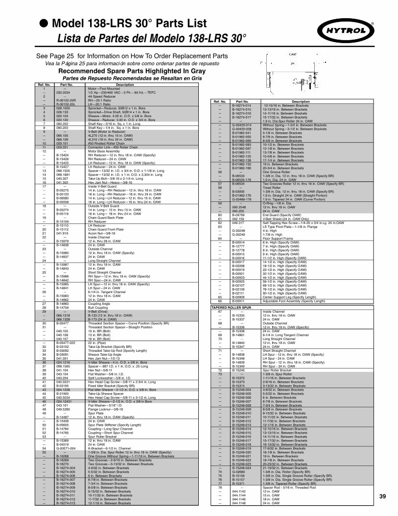
39
● Model 138-LRS 30° Parts List Lista de Partes del Modelo 138-LRS 30°
See Page 25 for Information on How To Order Replacement Parts
Recommended Spare Parts Highlighted In GrayVea la Página 25 para información sobre como ordenar partes de repuesto
Partes de Repuesto Recomendadas se Resaltan en Gris
TAPERED ROLLER SPUR67 — Inside Channel— B-15335 12 in. thru 18 in. OAW— B-15337 24 in. OAW68 — Outside Channel— B-15336 12 in. thru 18 in. OAW (Specify)— B-15338 24 in. OAW69 B-14861 6-1/4 in. Long Tangent Channel70 — Long Straight Channel— B-14840 12 in. thru 18 in. OAW— B-15347 24 in. OAW71 — Short Straight Channel— B-14838 LH Spur - 12 in. thru 18 in. OAW (Specify)— B-15348 LH Spur - 24 in. OAW— B-14839 RH Spur - 12 in. thru 18 in. OAW (Specify)— B-15349 RH Spur - 24 in. OAW72 B-15246 Spur Roller Bracket73 — 1-3/8 in. Spur Roller— B-15372 1-11/16 in. Between Brackets— B-15373 2-9/16 in. Between Brackets— B-15374 3-13/32 in. Between Brackets— B-15248-004 4-9/32 in. Between Brackets— B-15248-005 5-5/32 in. Between Brackets— B-15248-006 6 in. Between Brackets— B-15248-007 6-7/8 in. Between Brackets— B-15248-008 7-3/4 in. Between Brackets— B-15248-009 8-5/8 in. Between Brackets— B-15248-010 9-15/32 in. Between Brackets— B-15248-011 10-11/32 in. Between Brackets— B-15248-012 11-7/32 in. Between Brackets— B-15248-013 12-1/16 in. Between Brackets— B-15248-014 12-15/16 in. Between Brackets— B-15248-015 13-13/16 in. Between Brackets— B-15248-016 14-11/16 in. Between Brackets— B-15248-017 15-17/32 in. Between Brackets— B-15248-018 16-13/32 in. Between Brackets— B-15248-019 17-9/32 in. Between Brackets— B-15248-020 18-1/8 in. Between Brackets— B-15248-021 19 in. Between Brackets— B-15248-022 19-7/8 in. Between Brackets— B-15248-023 20-23/32 in. Between Brackets— B-15248-024 21-19/32 in. Between Brackets74 G-02680 1-3/8 in. Dia. Roller (Specify BR)75 B-15156 1-3/8 in. Dia. Single Groove Roller (Specify BR)76 B-15157 1-3/8 in. Dia. Single Groove Roller (Specify BR)77 B-15371 1-3/8 in. Tapered Roller (Specify BR)78 — Spacer Rod - 5/16 in. Threaded Rod— 044.1142 12 in. OAW— 044.1144 15 in. OAW— 044.1146 18 in. OAW— 044.1148 24 in. OAW
Ref. No. Part No. Description1 — Motor—Foot Mounted— 030.2034 1/2 Hp—230/460 VAC—3 Ph.—60 Hz.—TEFC2 — 4A Speed Reducer— R-00152-20R RH—20:1 Ratio— R-00152-20L LH—20:1 Ratio3 028.1005 Sprocket—Reducer, 50B12 x 1 in. Bore4 028.133 Sprocket—Drive Shaft, 50B14 x 1 in. Bore5 020.104 Sheave—Motor, 3.00 in. O.D. x 5/8 in. Bore6 020.120 Sheave—Reducer, 5.00 in. O.D. x 3/4 in. Bore7 090.202 Shaft Key—3/16 in. Sq. x 1 in. Long8 090.203 Shaft Key—1/4 in. Sq. x 1 in. Bore9 — V-Belt (Motor to Reducer)— 066.105 4L270 (12 in. thru 15 in. OAW)— 066.109 4L310 (18 in. thru 24 in. OAW)10 029.101 #50 Riveted Roller Chain11 029.201 Connector Link—#50 Roller Chain12 — Motor Base Assembly — B-15424 RH Reducer—12 in. thru 18 in. OAW (Specify)— B-15426 RH Reducer—24 in. OAW— B-15425 LH Reducer—12 in. thru 18 in. OAW (Specify)— B-15427 LH Reducer—24 in. OAW13 098.1505 Spacer—13/32 in. I.D. x 3/4 in. O.D. x 1-1/8 in. Long14 098.1681 Spacer—13/32 in. I.D. x 1 in. O.D. x 2.304 in. Long15 040.307 Take-Up Bolt—3/8-16 x 2-1/4 in. Long16 041.300 Hex Jam Nut—Heavy—3/8-1617 — Inside V-Belt Guard— B-05275 14 in. Long—RH Reducer—12 in. thru 18 in. OAW— B-05120 16 in. Long—RH Reducer—18 in. thru 24 in. OAW— B-06580 14 in. Long—LH Reducer—12 in. thru 15 in. OAW— B-05558 16 in. Long—LH Reducer—18 in. thru 24 in. OAW18 — Outside V-Belt Guard— B-05274 14 in. Long— 12 in. thru 15 in. OAW— B-05119 16 in. Long— 18 in. thru 24 in. OAW19 — Chain Guard Back Plate— B-15109 RH Reducer— B-15110 LH Reducer20 B-15112 Chain Guard Front Plate21 041.919 Acorn Nut—3/8-1622 — Inside Channel— B-15979 12 in. thru 28 in. OAW— B-14836 24 in. OAW23 — Outside Channel— B-15980 12 in. thru 18 in. OAW (Specify)— B-14837 24 in. OAW24 — Long Straight Channel— B-15987 12 in. thru 18 in. OAW— B-14843 24 in. OAW25 — Short Straight Channel— B-15986 RH Spur—12 in. thru 18 in. OAW (Specify)— B-14842 RH Spur—24 in. OAW— B-15985 LH Spur—12 in. thru 18 in. OAW (Specify)— B-14841 LH Spur—24 in. OAW26 — 6-1/4 in. Tangent Channel— B-15983 12 in. thru 18 in. OAW— B-14862 24 in. OAW27 B-14860 Coupling Angle28 B-14756 Butt Coupling29 — V-Belt (Drive)— 066.1318 B-133 (12 in. thru 18 in. OAW)— 066.1328 B-173 (24 in. OAW)30 B-05477 Threaded Section Spacer—Curve Position (Specify BR)31 — Threaded Section Spacer—Straight Position— 040.105 10 in. BR (Bolt)— 040.106 13 in. BR (Bolt)— 040.107 16 in. BR (Bolt)— B-05477-022 22 in. (Pipe)32 B-03102 Take-Up Bracket (Specify BR)33 B-03092 Threaded Take-Up Rod (Specify Length)34 B-03091 Sheave Take-Up Angle35 041.201 Hex Jam Nut—1/2-1336 024.1216 V-Idler Sheave—4 in. O.D. x 5/8 in. Bore37 098.1565 Spacer—.687 I.D. x 1 in. O.D. x .25 Long38 041.104 Hex Nut—5/8-1139 043.104 Flat Washer—5/8 in. I.D.40 043.204 Split Lockwasher—5/8 in. I.D.41 040.5031 Hex Head Cap Screw—5/8-11 x 2-3/4 in. Long42 B-03195 Fixed Idler Bracket (Specify BR)43 024.1226 Flat Idler Sheave—5-1/2 in. O.D. x 5/8 in. Bore44 B-21900 Take-Up Sheave Spacer45 040.5034 Hex Head Cap Screw—5/8-11 x 3-1/2 in. Long46 024.12431 V-Idler Sheave—2-1/2 in. O.D. x 3/8 in Bore 47 043.101 Flat Washer—5/16" I.D.48 049.5285 Flange Locknut—3/8-1649 — Spur Plate— B-14487 12 in. thru 18 in. OAW (Specify)— B-15406 24 in. OAW50 B-05605 Spur Plate Stiffener (Specify Length)51 B-14784 Coupling—Long Spur Channel52 B-14785 Coupling—Short Spur Channel53 — Spur Roller Bracket— B-15369 12 in. thru 18 in. OAW— B-04519 24 in. OAW54 G-00571-004 K-Bracket—6-1/2 in. Channel55 — 1-3/8 in. Dia. Spur Roller 12 in. thru 18 in. OAW (Specify)— B-16268 One Groove Without Spring—1-11/16 in. Between Brackets— B-16269 Two Grooves—2-9/16 in. Between Brackets— B-16270 Two Grooves—3-13/32 in. Between Brackets— B-16274-004 4-9/32 in. Between Brackets— B-16274-005 5-5/32 in. Between Brackets— B-16274-006 6 in. Between Brackets— B-16274-007 6-7/8 in. Between Brackets— B-16274-008 7-3/4 in. Between Brackets— B-16274-009 8-5/8 in. Between Brackets— B-16274-010 9-15/32 in. Between Brackets— B-16274-011 10-11/32 in. Between Brackets— B-16274-012 11-7/32 in. Between Brackets— B-16274-013 12-1/16 in. Between Brackets
Ref. No. Part No. Description— B-16274-014 12-15/16 in. Between Brackets— B-16274-015 13-13/16 in. Between Brackets— B-16274-016 14-11/16 in. Between Brackets— B-16274-017 15-17/32 in. Between Brackets— — 1.9 in. Dia.Spur Roller 24 in. OAW— G-00420-014 Without Spring—1-3/4 in. Between Brackets — G-00420-028 Without Spring—3-1/2 in. Between Brackets — B-01982-041 5-1/8 in. Between Brackets— B-01982-055 6-7/8 in. Between Brackets— B-01982-069 8-5/8 in. Between Brackets— B-01982-083 10-1/2 in. Between Brackets— B-01982-097 12-1/8 in. Between Brackets— B-01982-111 13-7/8 in. Between Brackets— B-01982-125 15-5/8 in. Between Brackets— B-01982-138 17-1/4 in. Between Brackets— B-01982-152 19 in. Between Brackets— B-01982-166 20-3/4 in. Between Brackets56 — One Groove Roller— B-06533 1-3/8 in. Dia. 12 in. thru 18 in. OAW (Specify BR)— B-06535-176 1.9 in. Dia. 24 in. OAW57 B-06534 Two Grooves Roller 12 in. thru 18 in. OAW (Specify BR)58 — Tread Roller— B-03935 1-3/8 in. Dia. 12 in. thru 18 in. OAW (Specify BR)— B-01982-176 1.9 in. Straight 24 in. OAW (Straight Portion)— G-00486-176 1.9 in. Tapered 24 in. OAW (Curve Portion)59 — O-Ring—1/8 in. Dia.— 090.2548 12 in. thru 18 in. OAW— 090.255 24 in. OAW60 B-09799 End Guard (Specify OAW)61 092.159 V-Belt Shield (24 in. OAW Only)62 049.317 Self-Tapping Hex Screw—1/4-20 x 3/4 in.Lg. 24 in.OAW63 — LS Type Pivot Plate—1-1/8 in. Flange— G-00248 4 in. High— G-00249 1-7/8 in. High64 — Floor Support Frame— B-00914 6 in. High (Specify OAW)— B-12777 7 in. High (Specify OAW)— B-12778 8 in. High (Specify OAW)— B-00915 9 in. High (Specify OAW)— B-00916 11-1/2 in. High (Specify OAW)— B-00917 14-1/2 in. High (Specify OAW)— B-02098 18-1/2 in. High (Specify OAW)— B-00919 22-1/2 in. High (Specify OAW)— B-00921 32-1/2 in. High (Specify OAW)— B-00923 44-1/2 in. High (Specify OAW)— B-00925 56-1/2 in. High (Specify OAW)— B-02107 68-1/2 in. High (Specify OAW)— B-02109 78-1/2 in. High (Specify OAW)— B-02111 90-1/2 in. High (Specify OAW)65 B-00909 Center Support Leg (Specify Length)66 B-00911 Adjustable Foot Assembly (Specify Length)

40
DETAIL “A”
*See Page 46 for Slave Connection
SECTION “B-B”
(VEA LA PAGINA 45PARARETENEDORES DE POLEA)
(*Vea la Página 46 para la Conexión Esclavada)
(DETALLE “A”)
(SECCION “B-B”)
● Model 138-LRSS 45° Parts Drawing Dibujo de Partes del Modelo 138-LRSS 45°
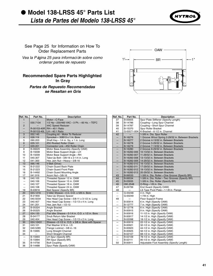
Ref. No. Part No. Description37 B-05605 Spur Plate Stiffener (Specify Length)38 B-14786 Coupling—Long Spur Channel39 B-14787 Coupling—Short Spur Channel40 B-15370 Spur Roller Bracket41 G-00571-004 K-Bracket—6-1/2 in. Channel42 — 1-3/8 in. Dia. Spur Roller — B-16276 1 Groove W/out Spring 2-29/32 in. Between Brackets— B-16277 2 Groove 4-13/32 in. Between Brackets— B-16278 2 Groove 5-29/32 in. Between Brackets— B-16279 2 Groove 7-13/32 in. Between Brackets— B-16280 2 Groove 8-29/32 in. Between Brackets— B-16282-006 10-13/32 in. Between Brackets— B-16282-007 11-29/32 in. Between Brackets— B-16282-008 13-13/32 in. Between Brackets— B-16282-009 14-29/32 in. Between Brackets— B-16282-010 16-13/32 in. Between Brackets— B-16282-011 17-29/32 in. Between Brackets— B-16282-012 19-13/32 in. Between Brackets— B-16282-013 20-29/32 in. Between Brackets43 B-06533 1-3/8 in. Dia. Roller—One Groove (Specify BR)44 B-06534 1-3/8 in. Dia. Roller—Two Grooves (Specify BR)45 B-03935 1-3/8 in. Dia. Roller (Specify BR)46 090.2548 O-Ring—1/8 in. Dia.47 B-09799 End Guard (Specify OAW)48 — LS Type Pivot Plate—1-1/8 in. Flange— G-00248 4 in. High— G-00249 1-7/8 in. High49 — Floor Support Frame— B-00914 6 in. High (Specify OAW)— B-12777 7 in. High (Specify OAW)— B-12778 8 in. High (Specify OAW)— B-00915 9 in. High (Specify OAW)— B-00916 11-1/2 in. High (Specify OAW)— B-00917 14-1/2 in. High (Specify OAW)— B-02098 18-1/2 in. High (Specify OAW)— B-00919 22-1/2 in. High (Specify OAW)— B-00921 32-1/2 in. High (Specify OAW)— B-00923 44-1/2 in. High (Specify OAW)— B-00925 56-1/2 in. High (Specify OAW)— B-02107 68-1/2 in. High (Specify OAW)— B-02109 78-1/2 in. High (Specify OAW)— B-02111 90-1/2 in. High (Specify OAW)50 B-00911 Adjustable Foot Assembly (Specify Length)
41
● Model 138-LRSS 45° Parts List Lista de Partes del Modelo 138-LRSS 45°
See Page 25 for Information on How ToOrder Replacement Parts
Recommended Spare Parts HighlightedIn Gray
Vea la Página 25 para información sobre comoordenar partes de repuesto
Partes de Repuesto Recomendadasse Resaltan en Gris
Ref. No. Part No. Description1 — Motor—C-Face— 030.7134 1/2 Hp—230/460 VAC—3 Ph.—60 Hz.—TEFC2 — 4AC Speed Reducer— R-00153-40R RH—40:1 Ratio— R-00153-40L LH—40:1 Ratio3 052.145 Coupling kit - Motor To Reducer4 028.119 Sprocket— 50B13 x 1 in. Bore5 090.203 Shaft Key—1/4 in. Sq. x 1 in. Long6 029.101 #50 Riveted Roller Chain7 029.201 Connector Link—#50 Roller Chain8 B-06629 Motor Base Assembly (Specify OAW)9 B-15008 Motor Base Support Angle—LH10 B-15009 Motor Base Support Angle—RH11 040.307 Take-Up Bolt—3/8-16 x 2-1/4 in. Long12 041.300 Hex Jam Nut—Heavy—3/8-1613 066.146 V-Belt (Drive)14 B-21222 Chain Guard Back Plate15 B-21223 Chain Guard Front Plate16 B-14492 Chain Guard Mounting Angle17 041.919 Acorn Nut—3/8-1618 040.105 Threaded Spacer 12 in. OAW— 040.106 Threaded Spacer 15 in. OAW— 040.107 Threaded Spacer 18 in. OAW— 040.108 Threaded Spacer 24 in. OAW19 B-03916 Bed Spacer (Specify BR)20 024.1216 V-Idler Sheave—4 in. O.D. x 5/8 in. Bore21 B-21900 Take-Up Sheave Spacer22 040.5034 Hex Head Cap Screw—5/8-11 x 3-1/2 in. Long23 040.407 Hex Head Cap Screw—1/2-13 x 4 in. Long24 041.201 Hex Jam Nut—1/2-1325 B-05324 Angle Bracket26 B-05325 Angle Bracket27 024.133 Flat Idler Sheave—3-1/4 in. O.D. x 1/2 in. Bore28 B-04177 Snub Return Idler Bracket29 040.404 Hex Head Cap Screw—1/2-13 x 2 in. Long30 024.12431 Sheave—2-1/2 in. O.D. x 3/8 in. Bore with Spacer31 043.101 Flat Washer 5/16 in. I.D.32 049.5285 Flange Locknut—3/8 in.-1633 B-15995 Long Straight Channel34 — Short Straight Channel— B-15993 LH Spur (Specify BR)— B-15994 RH Spur (Specify BR)35 B-14756 Butt Coupling36 B-14488 Spur Plate (Specify OAW)

42*See Page 46 for Slave Connection
DETAIL “A”
SECTION “B-B”
(VEA LA PAGINA 45PARARETENEDORES DE POLEA)
(*Vea la Página 46 para la Conexión Esclavada)
(DETALLE “A”)
(SECCION “B-B”)
● Model 138-LRSS 30° Parts Drawing Dibujo de Partes del Modelo 138-LRSS 30°

43
● Model 138-LRSS 30° Parts List Lista de Partes del Modelo 138-LRSS 30°
See Page 25 for Information on How ToOrder Replacement Parts
Recommended Spare Parts HighlightedIn Gray
Vea la Página 25 para información sobre comoordenar partes de repuesto
Partes de Repuesto Recomendadasse Resaltan en Gris
Ref. No. Part No. Description1 — Motor—C-Face— 030.7134 1/2 Hp—230/460 VAC—3 Ph.—60 Hz.—TEFC2 — 4AC Speed Reducer— R-00153-40R RH—40:1 Ratio— R-00153-40L LH—40:1 Ratio3 052.145 Coupling kit - Motor To Reducer4 028.119 Sprocket— 50B13 x 1 in. Bore5 090.203 Shaft Key—1/4 in. Sq. x 1 in. Long6 029.101 #50 Riveted Roller Chain7 029.201 Connector Link—#50 Roller Chain8 B-06629 Motor Base Assembly (Specify OAW)9 B-15008 Motor Base Support Angle—LH10 B-15009 Motor Base Support Angle—RH11 040.307 Take-Up Bolt—3/8-16 x 2-1/4 in. Long12 041.300 Hex Jam Nut—Heavy—3/8-1613 066.146 V-Belt (Drive)14 B-21222 Chain Guard Back Plate15 B-21223 Chain Guard Front Plate16 B-14492 Chain Guard Mounting Angle17 041.919 Acorn Nut—3/8-1618 040.105 Threaded Spacer 12 in. OAW— 040.106 Threaded Spacer 15 in. OAW— 040.107 Threaded Spacer 18 in. OAW— 040.108 Threaded Spacer 24 in. OAW19 B-03916 Bed Spacer (Specify BR)20 024.1216 V-Idler Sheave—4 in. O.D. x 5/8 in. Bore21 B-21900 Take-Up Sheave Spacer22 040.5034 Hex Head Cap Screw—5/8-11 x 3-1/2 in. Long23 040.407 Hex Head Cap Screw—1/2-13 x 4 in. Long24 041.201 Hex Jam Nut—1/2-1325 B-05324 Angle Bracket26 B-05325 Angle Bracket27 024.133 Flat Idler Sheave—3-1/4 in. O.D. x 1/2 in. Bore28 B-04177 Snub Return Idler Bracket29 040.404 Hex Head Cap Screw—1/2-13 x 2 in. Long30 024.12431 Sheave—2-1/2 in. O.D. x 3/8 in. Bore with Spacer31 043.101 Flat Washer 5/16 in. I.D.32 049.5285 Flange Locknut—3/8 in.-1633 B-15995 Long Straight Channel34 — Short Straight Channel— B-15991 LH Spur (Specify BR)— B-15992 RH Spur (Specify BR)35 B-14756 Butt Coupling36 B-14487 Spur Plate (Specify OAW)37 B-05605 Spur Plate Stiffener (Specify Length)38 B-14784 Coupling—Long Spur Channel39 B-14785 Coupling—Short Spur Channel40 B-15369 Spur Roller Bracket41 G-00571-004 K-Bracket—6-1/2 in. Channel
Ref. No. Part No. Description42 — 1-3/8 in. Dia. Spur Roller — B-16268 1 Groove W/out Spring 1-11/16 in. Between Brackets— B-16269 2 Groove 2-9/16 in. Between Brackets— B-16270 2 Groove 3-13/32 in. Between Brackets— B-16271 2 Groove 4-9/32 in. Between Brackets— B-16272 1 Groove 5-5/32 in. Between Brackets— B-16274-006 6 in. Between Brackets— B-16274-007 6-7/8 in. Between Brackets— B-16274-008 7-3/4 in. Between Brackets— B-16274-009 8-5/8 in. Between Brackets— B-16274-010 9-15/32 in. Between Brackets— B-16274-011 10-11/32 in. Between Brackets— B-16274-012 11-7/32 in. Between Brackets— B-16274-013 12-1/16 in. Between Brackets— B-16274-014 12-15/16 in. Between Brackets— B-16274-015 13-13/16 in. Between Brackets— B-16274-016 14-11/16 in. Between Brackets— B-16274-017 15-17/32 in. Between Brackets— B-16274-018 16-13/32 in. Between Brackets— B-16274-019 17-9/32 in. Between Brackets— B-16274-020 18-1/8 in. Between Brackets— B-16274-021 19 in. Between Brackets— B-16274-022 19-7/8 in. Between Brackets— B-16274-023 20-23/32 in. Between Brackets— B-16274-024 21-19/32 in. Between Brackets43 B-06533 1-3/8 in. Dia. Roller—One Groove (Specify BR)44 B-06534 1-3/8 in. Dia. Roller—Two Grooves (Specify BR)45 B-03935 1-3/8 in. Dia. Roller (Specify BR)46 090.2548 O-Ring—1/8 in. Dia.47 B-09799 End Guard (Specify OAW)48 — LS Type Pivot Plate—1-1/8 in. Flange— G-00248 4 in. High— G-00249 1-7/8 in. High49 — Floor Support Frame— B-00914 6 in. High (Specify OAW)— B-12777 7 in. High (Specify OAW)— B-12778 8 in. High (Specify OAW)— B-00915 9 in. High (Specify OAW)— B-00916 11-1/2 in. High (Specify OAW)— B-00917 14-1/2 in. High (Specify OAW)— B-02098 18-1/2 in. High (Specify OAW)— B-00919 22-1/2 in. High (Specify OAW)— B-00921 32-1/2 in. High (Specify OAW)— B-00923 44-1/2 in. High (Specify OAW)— B-00925 56-1/2 in. High (Specify OAW)— B-02107 68-1/2 in. High (Specify OAW)— B-02109 78-1/2 in. High (Specify OAW)— B-02111 90-1/2 in. High (Specify OAW)50 B-00911 Adjustable Foot Assembly (Specify Length)

44
Ref. No. Part No. Description1 — Sheave Retaining Bracket— B-14920 10 in. BR— B-14921 13 in. BR— B-14471 16 in. thru 22 in. BR (Specify)2 B-07584 Bearing Pedestal3 010.3012 Pillow Block Bearing—1 in. Bore4 B-14719 Flange Bearing Bracket5 010.0022 2-Bolt Flange Bearing—1 in. Bore6 B-14388 Drive Shaft (Specify BR)7 B-14386 Drive Shaft with Slave (Specify BR)
B-15131
DRIVE END 12” - 24” OAW DRIVE END WITH SLAVE 12” - 24” OAW
B-5132
B-15134 B-4504
12” OAW IDLER END 15” — 24” OAW IDLER END
IDLER END WITH SLAVE 12” - 24” OAW
B-15133
● Model 138-ACC Sheave Retainers DrawingsRetenedores de Polea del Modelo 138-ACC
See Page 25 for Information on How To Order Replacement Parts
Recommended Spare Parts Highlighted In Gray
Vea la Página 25 para información sobre como ordenar partes de repuesto
Partes de Repuesto Recomendadas se Resaltan en Gris
Ref. No. Part No. Description8 — Idler Shaft— B-14385 12 in. OAW— B-17066 15 in. thru 24 in. OAW9 B-15386 Idler Shaft with Slave10 049.201 Spacer—1 in. I.D. x 1-1/4 in. O.D. x 1/8 in. Long11 098.1537 Spacer—1 in. I.D. x 1-1/4 in. O.D. x 11/16 in. Long12 B-10776 Spacer—1 in. I.D. x 1-1/4 in. O.D. x 2-3/8 in. Long13 024.1282 Drive Sheave (Double)—5-3/4 in. O.D. x 1 in. Bore14 049.305 External Retaining Ring—1 in. Dia. Shaft

45
DRIVE END 12” - 24” OAW DRIVE END WITH SLAVE 12” - 24” OAW
12” OAW IDLER END 15” — 24” OAW IDLER END
IDLER END WITH SLAVE 12” - 24” OAW
Ref. No. Part No. Description1 — Sheave Retaining Bracket— B-14920 10 in. BR— B-14921 13 in. BR— B-14471 16 in. thru 22 in. BR (Specify)2 B-07584 Bearing Pedestal3 010.3012 Pillow Block Bearing—1 in. Bore4 B-14719 Flange Bearing Bracket5 010.0022 2-Bolt Flange Bearing—1 in. Bore6 B-14388 Drive Shaft (Specify BR)7 B-14386 Drive Shaft with Slave (Specify BR)
B-15126 B-15127
B-15129 B-15130
B-15128
● 138-LRC, LRS, & LRSS Sheave Retainers Drawings Retenedores de Polea Modelos 138-LRC, LRS & LRSS
See Page 25 for Information on How To Order Replacement Parts
Recommended Spare Parts Highlighted In Gray
Vea la Página 25 para información sobre como ordenar partes de repuesto
Partes de Repuesto Recomendadas se Resaltan en Gris
Ref. No. Part No. Description8 — Idler Shaft— B-14385-012 12 in. OAW— B-17066 15 in. thru 24 in. OAW9 B-22628 Idler Shaft with Slave10 098.1538 Spacer—1 in. I.D. x 1-1/4 in. O.D. x 13/16 in. Long11 098.169 Spacer—1 in. I.D. x 1-1/4 in. O.D. x 1-5/8 in. Long12 024.128 Drive Sheave (Single)—5-3/4 in. O.D. x 1 in. Bore13 049.305 External Retaining Ring—1 in. Dia. Shaft14 098.1541 Spacer—1 in. I.D. x 1-1/4 in. O.D. x 29/32 in. Long

46
Ref. No. Part No. Description1 B-15239 Chain Guard Back Plate2 B-15241 Chain Guard Front Plate3 B-16679 Chain Guard Mounting Bracket4 041.919 Acorn Nut—3/8-165 099.496 Take-Up Block6 042.559 Carriage Bolt—5/16-18 x 2 in. Long7 049.551 Wing Nut—5/16-188 028.134 Sprocket—50B16 x 1 in. Bore9 090.203 Shaft Key—1/4 in. Sq. x 1 in. Long10 029.101 #50 Roller Chain11 029.201 Connector Link—#50 Roller Chain
● Slave Connection Parts Drawing & Part ListDibujo y Lista de Partes de la Conexión Esclavada
See Page 25 for Information on How To Order Replacement Parts
Recommended Spare Parts Highlighted In Gray
Vea la Página 25 para información sobre como ordenar partes de repuesto
Partes de Repuesto Recomendadas se Resaltan en Gris

47
● NOTES

HYTROL CONVEYOR COMPANY, INC.2020 Hytrol Drive
Jonesboro, Arkansas 72401U.S.A.
Phone: (870) 935-3700
EFFECTIVE FEBRUARY 2007
Printed by Master Printing 2/07
www.hytrol.com