do not edit bmg in indentation ismanam2013
TRANSCRIPT

Mechanical behaviour of Zr‐based metallic glass in indentation
Presented By: Vaibhav Phadnis
Vahid NekouieGayan Abeygunawardane‐Arachchige
Anish RoyVadim Silberschmidt
Wolfson School of Mechanical & Manufacturing Engineering, Loughborough UniversityUta Kühn
IFW/Dresden
1

Introduction & Motivation
Metallic glass shows unique mechanical properties Evidence of length scale effects Deformation mechanisms of metallic glass are unique
plastic shear flow in the microscale, but brittle fracture in macroscale deformation induced ductilization
Ultimate goal is to predict component deformation under macroscopically homogeneous loads
2

BMG Material
BMG alloy manufactured at IFW/DresdenZr48Cu36Al8Ag8 Samples: 70 mm × 10 mm × 2 mm ; 40 mm × 30 mm × 1.5 mm
3NCRC Confidential & Privileged Information - Copyright, NCRC, 2007
Outline: Mechanical characterisation of the BMG alloy Macroscale Microscale Nanoscale
Constitutive material modelling and Finite Element Analysis

Macroscale
Bending Tests Elastic Modulus Poisson’s ratio
DMA
4
E [GPa] ν Tg [°C]
In‐house experiments 80 – 86 0.34 – 0.35 425 ± 3
Date from IFW 98 – 102 430 ± 3
Literature 115 417

5ISMANAM 2013
Crystalline phase
XRD results show :
(i) The structure of the metallic glass is not completely amorphous.
(ii) There are crystalline phases in the materials and these phases are not
uniformly dispersed in the materials.
Macroscale
XRDCrystalline phase

6
Nano/Micro Test (Micro Materials Ltd.)
Tests performed:
Nano and Micro‐indentation
Load rate: (0.1, 1, 2,10 mN/s)
Cyclic loading
Spherical Indenter
Micro: r = 50 μm
Nano: r = 5 μm
Nano‐Micro indentation studies
Sample is cut Polished Zygo Talisurf
Ra = 2 to 3 nm

7NCRC Confidential & Privileged Information - Copyright, NCRC, 2007
NanoindentationLoading Rate = 0.1 mN/sec
Cyclic loading was performed to determine initiation of plastic deformation (pop‐in)
Load = 2 mN
Fully Elastic deformation
Load = 3 mN
Initiation of plasticity

8NCRC Confidential & Privileged Information - Copyright, NCRC, 2007
NanoindentationLoading Rate = 0.1 mN/sec
Cyclic loading was performed to determine initiation of plastic deformation (pop‐in)
Pop‐in

Nanoindentation

10
Nanoindentation
130 mN 190 mN 220 mN
Maximum load 275 mN
220 mN
190 mN
130 mN
11
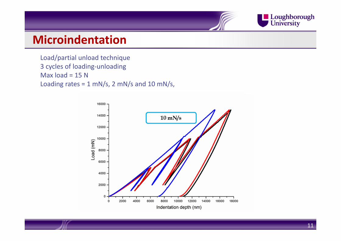
MicroindentationLoad/partial unload technique3 cycles of loading‐unloadingMax load = 15 NLoading rates = 1 mN/s, 2 mN/s and 10 mN/s,

Microindentation: SEM
Load < 10 NNo shear bands visible
12

13
10 mN/s
1 mN/s
Microindentation: SEM
14
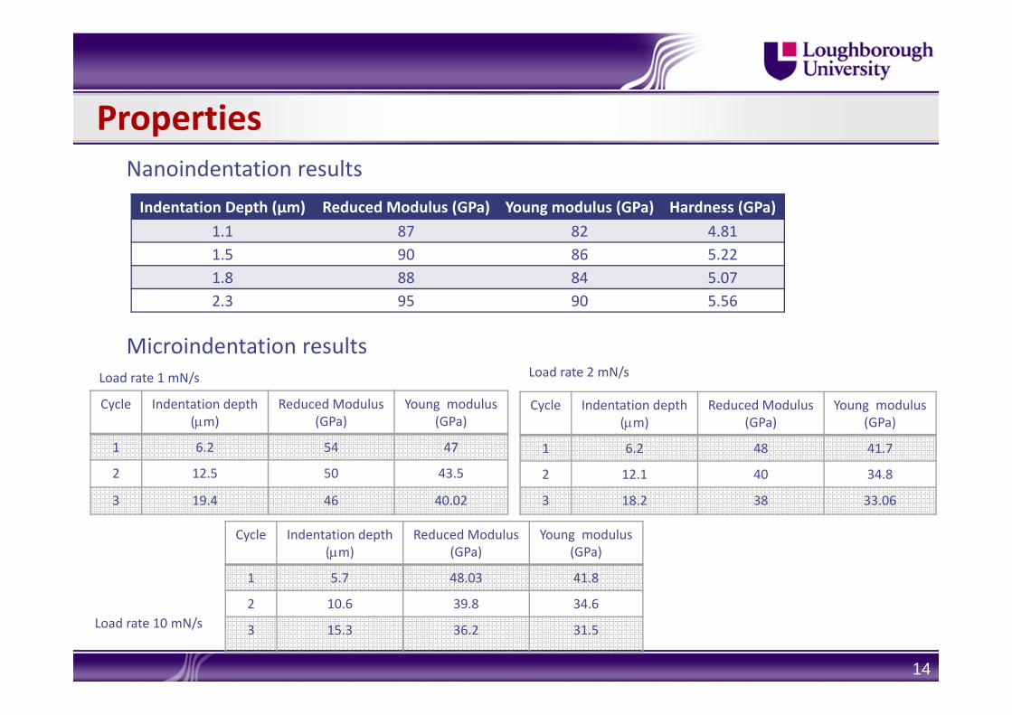
Indentation Depth (µm) Reduced Modulus (GPa) Young modulus (GPa) Hardness (GPa)1.1 87 82 4.811.5 90 86 5.221.8 88 84 5.072.3 95 90 5.56
Microindentation results
Properties
Cycle Indentation depth(m)
Reduced Modulus(GPa)
Young modulus(GPa)
1 6.2 54 47
2 12.5 50 43.5
3 19.4 46 40.02
Load rate 1 mN/s Load rate 2 mN/s
Cycle Indentation depth(m)
Reduced Modulus(GPa)
Young modulus(GPa)
1 6.2 48 41.7
2 12.1 40 34.8
3 18.2 38 33.06
Nanoindentation results
Load rate 10 mN/s
Cycle Indentation depth(m)
Reduced Modulus(GPa)
Young modulus(GPa)
1 5.7 48.03 41.8
2 10.6 39.8 34.6
3 15.3 36.2 31.5

MODELLING OF INDENTATION/Finite Element Modelling
15NCRC Confidential & Privileged Information - Copyright, NCRC, 2007
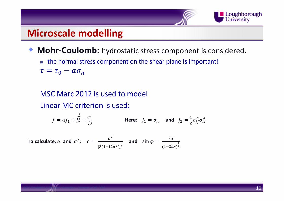
Microscale modelling Mohr‐Coulomb: hydrostatic stress component is considered.
the normal stress component on the shear plane is important!
MSC Marc 2012 is used to modelLinear MC criterion is used:
/Here: and
To calculate, and /: /
and sin
16NCRC Confidential & Privileged Information - Copyright, NCRC, 2007
17
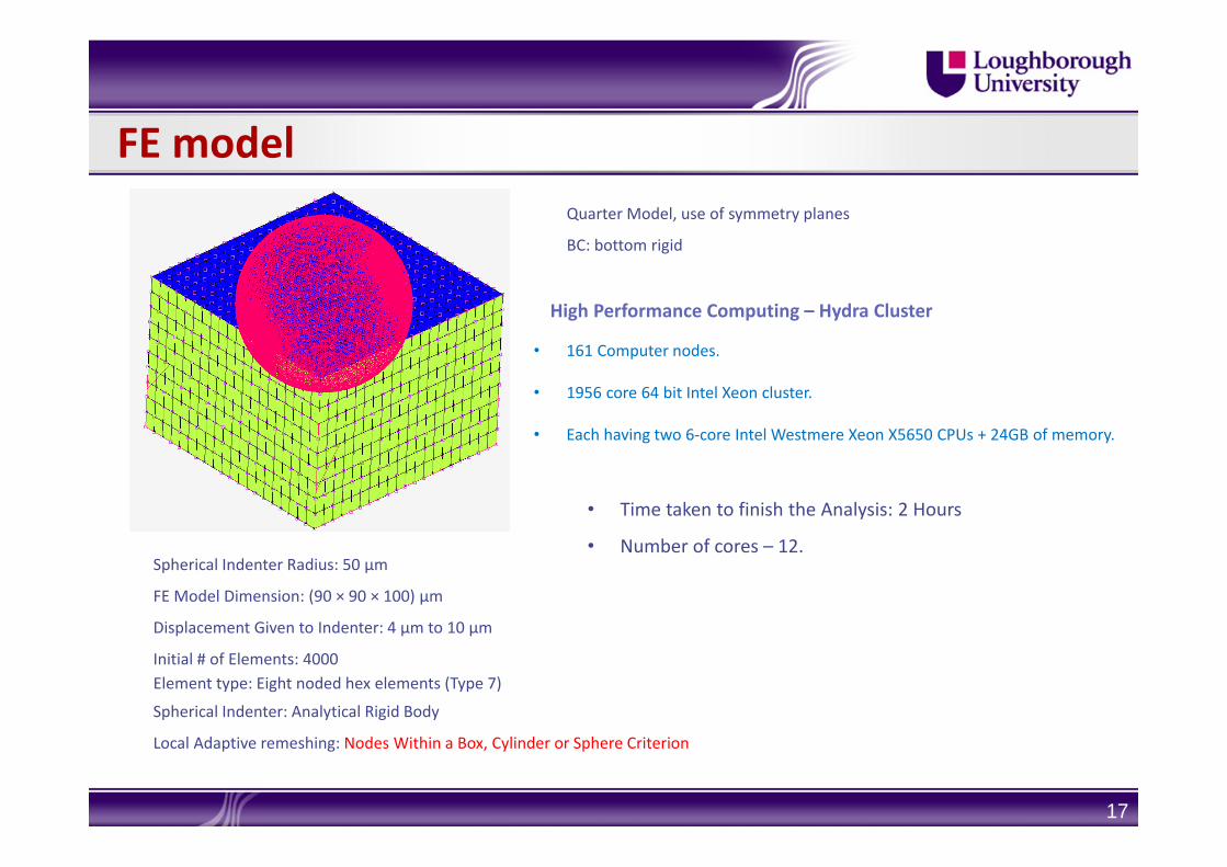
Spherical Indenter Radius: 50 μm
FE Model Dimension: (90 × 90 × 100) µm
Displacement Given to Indenter: 4 µm to 10 µm
Initial # of Elements: 4000Element type: Eight noded hex elements (Type 7)
Spherical Indenter: Analytical Rigid Body
Local Adaptive remeshing: Nodes Within a Box, Cylinder or Sphere Criterion
FE modelQuarter Model, use of symmetry planes
BC: bottom rigid
High Performance Computing – Hydra Cluster
• 161 Computer nodes.
• 1956 core 64 bit Intel Xeon cluster.
• Each having two 6‐core Intel Westmere Xeon X5650 CPUs + 24GB of memory.
• Time taken to finish the Analysis: 2 Hours
• Number of cores – 12.

18
Shear Stress Variation Normal Stress Variation
FE model: Results
End of Loading End of Unloading

19
FE model: Results
E (GPa) σ' (MPa) µ α
38 1500 0.2 0.02

Outlook: Why is there such a significant reduction in Modulus?
Shear bands ‘break up’ the amorphous material into islands of amorphous MG The shear bands help ‘slip’ these islands under macroscopic loads This will reduce the reaction force on the indenter ►reduced stiffness from experiments Material Damage needs to be characterised [in macroscopic modelling]
20NCRC Confidential & Privileged Information - Copyright, NCRC, 2007

Outlook
MC model is not appropriate for the BMG under study The process of deformation induces damage in the material. This damage needs to be characterised in the constitutive behaviour of the material. A gradient plasticity based approach is currently being developed to capture the effect of the local shear bands
21NCRC Confidential & Privileged Information - Copyright, NCRC, 2007

Indentation Profile: Cycle 1 loading‐unloading
22
Distance from the Indentor Axis (μm)
Inde
ntation De
pth (μm)
‐12
‐10
‐8
‐6
‐4
‐2
0
2
4
0 10 20 30 40 50 60 70 80
Indentor at Full displacement
Indentor Fully Extracted