doas heat pump with variable refrigerant flow (vrf)
TRANSCRIPT
- 1 -
DOAS HEAT PUMP WITH VARIABLE REFRIGERANT FLOW (VRF)
Titu R. Doctor, President, CENC Inc., Atlanta, GA, U.S.A, Member ASHRAE
Florin Gavrilut, Senior Design Engineer, CENC Inc., Atlanta, GA, U.S.A, Member ASHRAE Abstract. The paper is analyzing the concept of variable refrigerant flow Dedicated Outdoor Air System (DOAS) with Heat Pump function for summer cooling and winter heating. In recent years the air quality requested by implementing ASHRAE Standard 62.1 norms for fresh air led to large applications for DOAS. The implementation of DOAS comes with an increase of energy consumption and high cost of operation. Keeping in mind the reduction in energy consumption, one of the first premises is to recover the energy from the cold air or the hot air exhausted from the space served by the DOAS. Recognizing this fact the paper goes further to investigate other solutions in reducing the energy consumption. The climate characteristics for different locations are the base parameter for DOAS sizing. As a result the equipment is sized for the most unfavorable situation resulting in an operation of the equipment at 99% below its size. The application is for a region in the Eastern coast of the USA. The new technology of variable refrigerant flow is a perfect fit to follow the outdoor conditions for that specific location. The paper is analizing refrigerant schematics and the component selection for DOAS with VRF. The main reduction in energy consumption comes from the compressor running with variable flow. The paper analizes the two compressor schematic and practical results. Next, the selection of the expansion devices and air coils which shall adapt in corresponding manner to VRF. In conclusion, the paper advocates for a preferred selection of Variable Refrigerant Flow technology, heat recovery and water source Heat Pump for most of the DOAS. Key Words: DOAS, heat pumps, VRF, energy savings, air quality Introduction. The DOAS, also known as 100% Fresh Air System, is designed to provide the needed quantity of fresh air for a specified enclosure. The DOAS is built as a packaged equipment containing one or more mechanical refrigeration circuits including compressor, condenser, evaporator, and the adjacent components as expansion devices, refrigerant filters, receivers and accumulators as well as filters and an air moving device. Due to the possible high humidity of the outside air a DOAS is considered a dehumidification equipment and is calculated acordingly. In most climate aeas, the moisture in the outdoor air accounts for the largest portion of humidity loads. (Dickmann et al. 2007) Outside air conditions are variable during the entire year as well as during a full day. For that reason the local climate conditions are determining factors for the system sizing. The best representation of the outdoor conditions are the annual repartition of air temperatures and humidity. The maximum and minimum air temperatures with incidental high humidity are considered the base for designing the maximum capacity for the DOAS. DOAS is an HVAC equipment that decouples and separates the treatment of the outdoor air from the main HVAC system of the building before it is introduced in an air conditioned space. The need for outdoor air is defined by ANSI/ASHRAE Standard 62, Ventilation for Acceptable Indoor Air Quality, by mandating the air flow rate required for each application. The purpose of the equipment described in the present paper is to reduce the operation cost, mainly the energy usage, by modeling the capacity of the unit to the outdoor condition.
- 1 -
10thIEA Heat Pump Conference 2011
- 2 -
For the operation the unit uses a constant air flow determined by the request of fresh air which is distributed through the hallways of the building. Due to the size, the equipment does not have a heat recovery device installed but it is in the opinion of the authors that such devices will be mandatory in the future for all sizes. Total energy recovery (TER) devices will further reduce the size of the cooling parts (Mumma 2003). The system can be easily adapted to include a TER. Altough the unit has constant air flow we believe that a variable air flow would be practical for applications with partial occupancy schedules. An unoccupied schedule is provided in the control of the unit.
1 DESIGN CRITERIA 1.1 Outdoor Conditions Design conditions for DOAS are based on the climatic values for each specific geographical location. It is up to the designer to decide which set of conditions (probability of occurrence) are to be allowed for:
0.4, 1.0 or 2.0% cumulative frequency of occurrence.
For the sizing and rating of DOAS (Milliken 2008) two outdoor design conditions are considered: For the cooling season the annual cooling and dehumidification those values are the Dry Bulb temperature (DB) and the Mean Coincident Wet Bulb temperature (MCWB). For the heating season those values are the annual heating for DB, Dew Point (DP) and Mean Coincident Dry Bulb temperature (MCDB). In our application for Charlotte, NC, USA (ASHRAE 2009) the following design outdoor conditions are considered at 1.0% frequency of occurrence, which leave the risk that for 88 hours per year the annual conditions values might be exceeded. Cooling season annual values DB = 33.1°C and MCWB = 23.4°C Heating season annual values DB = - 4.1°C, DP = 6.7°C and MCDB = 29.0°C Table 1 presents the monthly average temperatures, relative humidity as well as the heating and cooling degree-days for the location. Table 1 Monthly average temperature and humidity for Charlotte, NC, U.S.A.
AIR TEMPERATURE
RELATIVE HUMIDITY
HEATING DEGREE–DAYS
COOLING DEGREE–D
°C % °C-d °C-d Jan 4.1 65.8% 431 0 Feb 5.9 61.9% 339 0 Mar 10.8 61.4% 223 25 Apr 15.6 59.3% 72 168 May 19.9 66.8% 0 307 Jun 23.7 69.6% 0 411 Jul 25.4 72.2% 0 477 Aug 24.9 73.4% 0 462 Sep 21.7 73.2% 0 351 Oct 15.8 69.8% 68 180 Nov 10.8 67.6% 216 24 Dec 6.0 67.4% 372 0
Annual 15.4 67.4% 1,721 2,405
- 2 -
10thIEA Heat Pump Conference 2011
- 3 -
1.2 Supply Conditions The psychometric control requirements under varying conditions are simplified by using only two points for the supply air, one after the evaporator and one at the supply. As mentioned, the DOAS is dehumidification equipment which reduces the moisture content from maximum outdoor conditions to a Supply Air Dew Point Temperature (SA-DPT) at an equal or lower value DP than the DP of the indoor space. SA-DPT for DOAS can be summarized for two kinds of applications in Table 2 for a conventional neutral delivery and for customized conditions. Table 2 Supply air conditions CONDITION SA-DPT DB Conventional neutral 13°C 22.2°C Request for additional space latent cooling by DOAS
between 9.6°C to 13°C variable
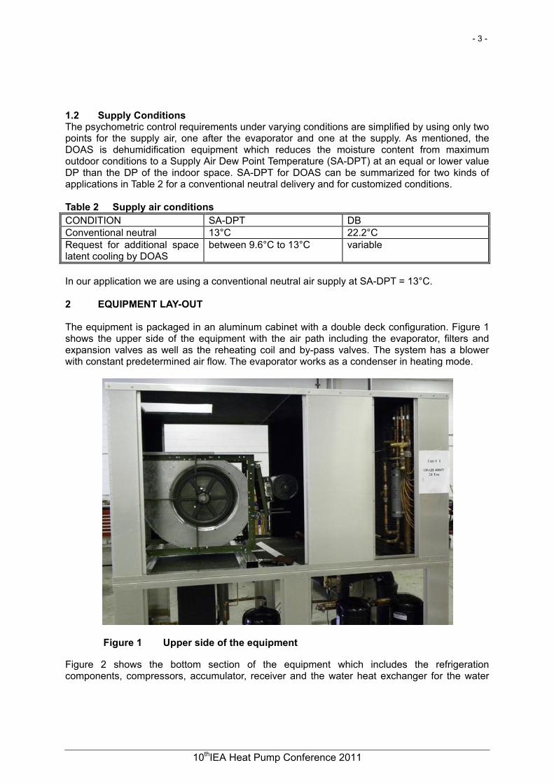
In our application we are using a conventional neutral air supply at SA-DPT = 13°C. 2 EQUIPMENT LAY-OUT The equipment is packaged in an aluminum cabinet with a double deck configuration. Figure 1 shows the upper side of the equipment with the air path including the evaporator, filters and expansion valves as well as the reheating coil and by-pass valves. The system has a blower with constant predetermined air flow. The evaporator works as a condenser in heating mode.
Figure 1 Upper side of the equipment
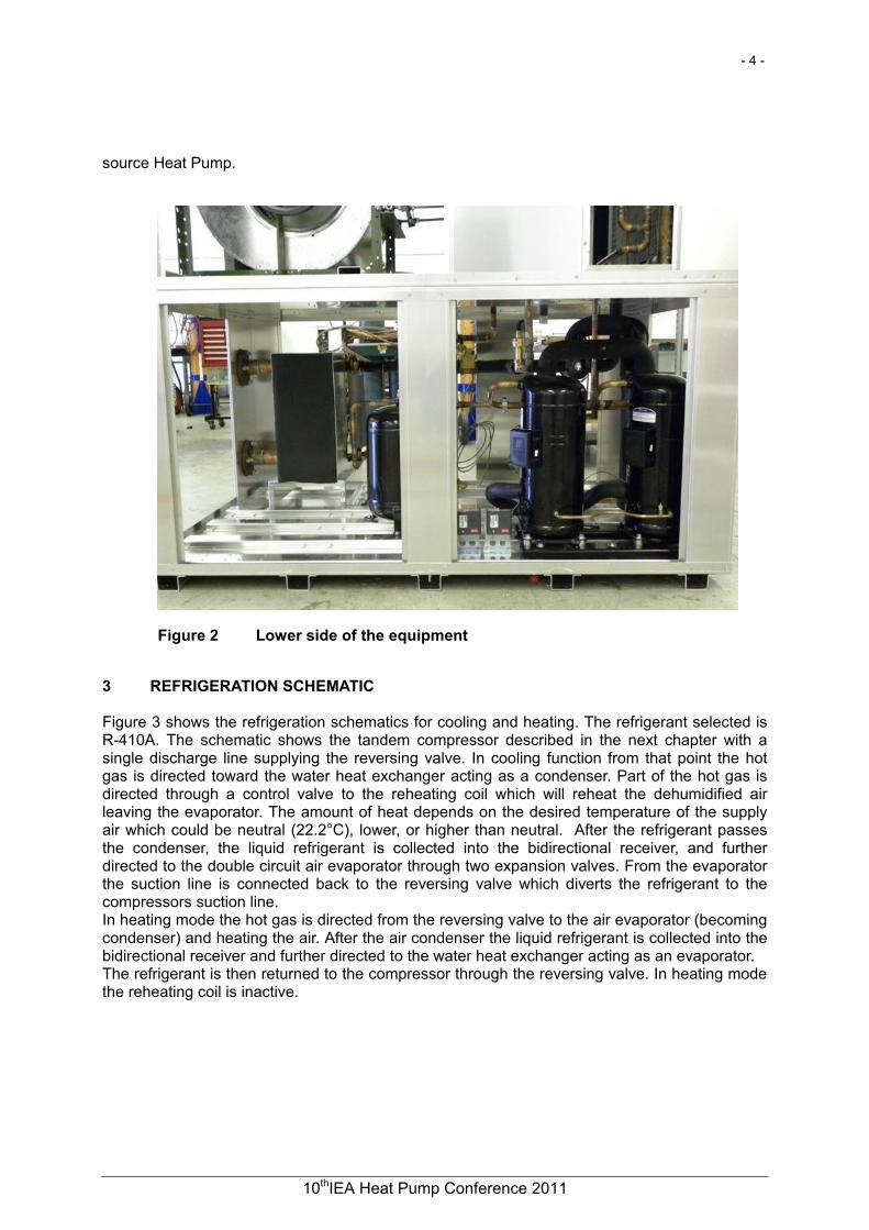
Figure 2 shows the bottom section of the equipment which includes the refrigeration components, compressors, accumulator, receiver and the water heat exchanger for the water
- 3 -
10thIEA Heat Pump Conference 2011
- 4 -
source Heat Pump.
Figure 2 Lower side of the equipment
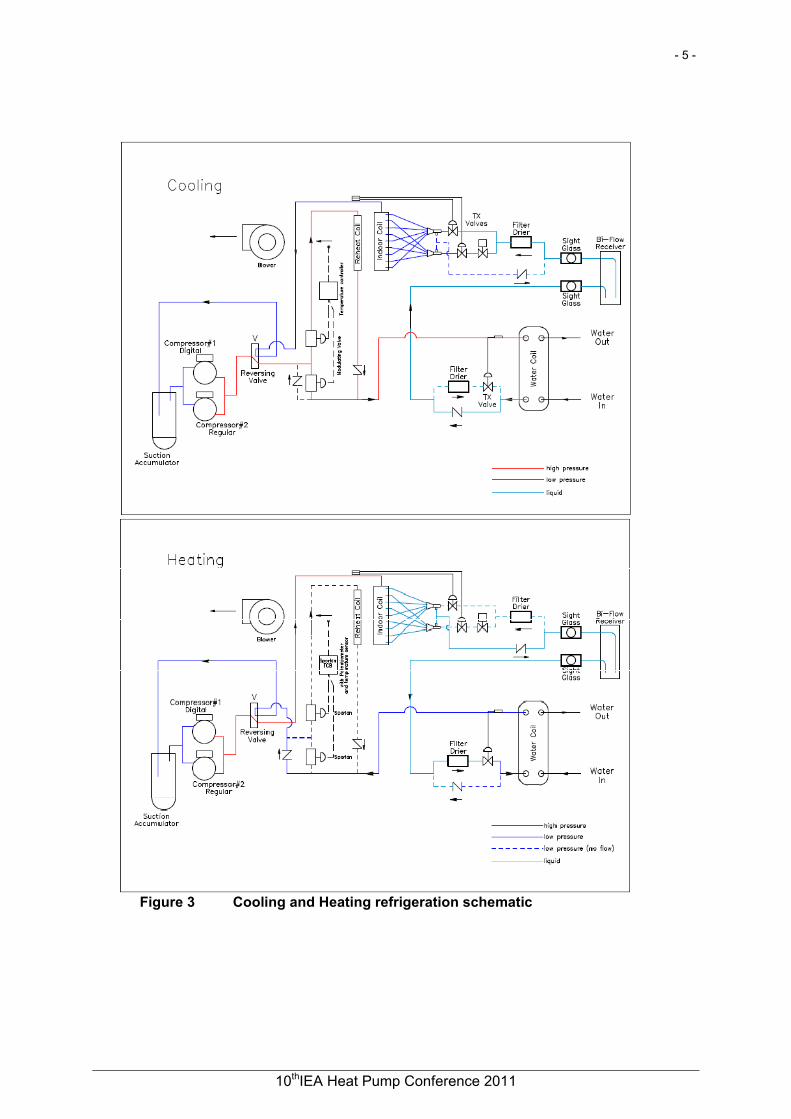
3 REFRIGERATION SCHEMATIC Figure 3 shows the refrigeration schematics for cooling and heating. The refrigerant selected is R-410A. The schematic shows the tandem compressor described in the next chapter with a single discharge line supplying the reversing valve. In cooling function from that point the hot gas is directed toward the water heat exchanger acting as a condenser. Part of the hot gas is directed through a control valve to the reheating coil which will reheat the dehumidified air leaving the evaporator. The amount of heat depends on the desired temperature of the supply air which could be neutral (22.2°C), lower, or higher than neutral. After the refrigerant passes the condenser, the liquid refrigerant is collected into the bidirectional receiver, and further directed to the double circuit air evaporator through two expansion valves. From the evaporator the suction line is connected back to the reversing valve which diverts the refrigerant to the compressors suction line. In heating mode the hot gas is directed from the reversing valve to the air evaporator (becoming condenser) and heating the air. After the air condenser the liquid refrigerant is collected into the bidirectional receiver and further directed to the water heat exchanger acting as an evaporator. The refrigerant is then returned to the compressor through the reversing valve. In heating mode the reheating coil is inactive.
- 4 -
10thIEA Heat Pump Conference 2011
- 5 -
Figure 3 Cooling and Heating refrigeration schematic
- 5 -
10thIEA Heat Pump Conference 2011
- 6 -
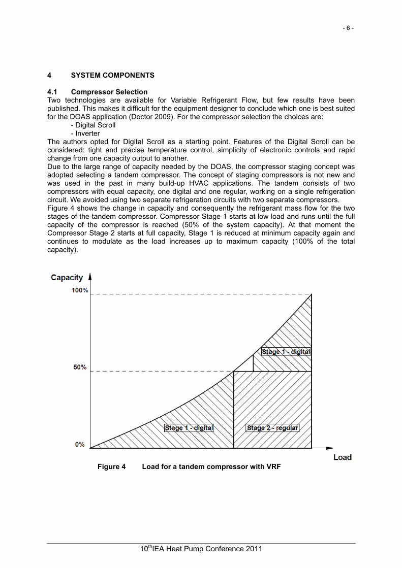
4 SYSTEM COMPONENTS 4.1 Compressor Selection Two technologies are available for Variable Refrigerant Flow, but few results have been published. This makes it difficult for the equipment designer to conclude which one is best suited for the DOAS application (Doctor 2009). For the compressor selection the choices are: - Digital Scroll - Inverter The authors opted for Digital Scroll as a starting point. Features of the Digital Scroll can be considered: tight and precise temperature control, simplicity of electronic controls and rapid change from one capacity output to another. Due to the large range of capacity needed by the DOAS, the compressor staging concept was adopted selecting a tandem compressor. The concept of staging compressors is not new and was used in the past in many build-up HVAC applications. The tandem consists of two compressors with equal capacity, one digital and one regular, working on a single refrigeration circuit. We avoided using two separate refrigeration circuits with two separate compressors. Figure 4 shows the change in capacity and consequently the refrigerant mass flow for the two stages of the tandem compressor. Compressor Stage 1 starts at low load and runs until the full capacity of the compressor is reached (50% of the system capacity). At that moment the Compressor Stage 2 starts at full capacity, Stage 1 is reduced at minimum capacity again and continues to modulate as the load increases up to maximum capacity (100% of the total capacity).
Figure 4 Load for a tandem compressor with VRF
- 6 -
10thIEA Heat Pump Conference 2011
- 7 -
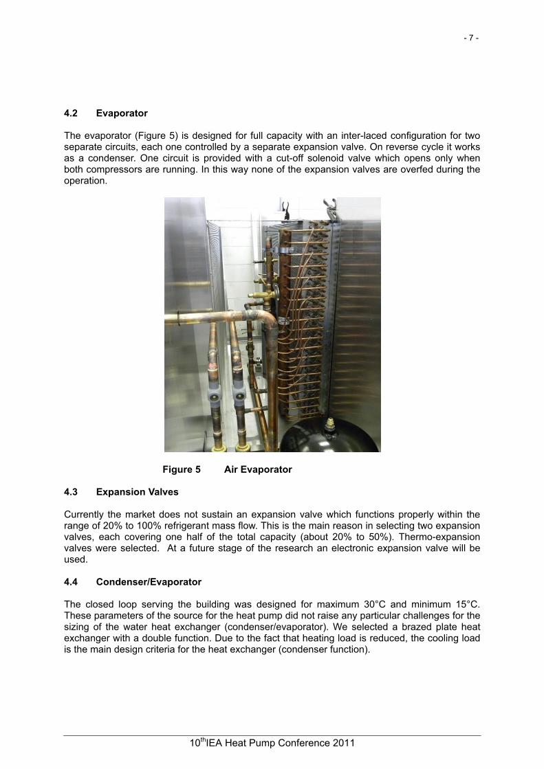
4.2 Evaporator The evaporator (Figure 5) is designed for full capacity with an inter-laced configuration for two separate circuits, each one controlled by a separate expansion valve. On reverse cycle it works as a condenser. One circuit is provided with a cut-off solenoid valve which opens only when both compressors are running. In this way none of the expansion valves are overfed during the operation.
Figure 5 Air Evaporator 4.3 Expansion Valves Currently the market does not sustain an expansion valve which functions properly within the range of 20% to 100% refrigerant mass flow. This is the main reason in selecting two expansion valves, each covering one half of the total capacity (about 20% to 50%). Thermo-expansion valves were selected. At a future stage of the research an electronic expansion valve will be used. 4.4 Condenser/Evaporator The closed loop serving the building was designed for maximum 30°C and minimum 15°C. These parameters of the source for the heat pump did not raise any particular challenges for the sizing of the water heat exchanger (condenser/evaporator). We selected a brazed plate heat exchanger with a double function. Due to the fact that heating load is reduced, the cooling load is the main design criteria for the heat exchanger (condenser function).
- 7 -
10thIEA Heat Pump Conference 2011
- 8 -
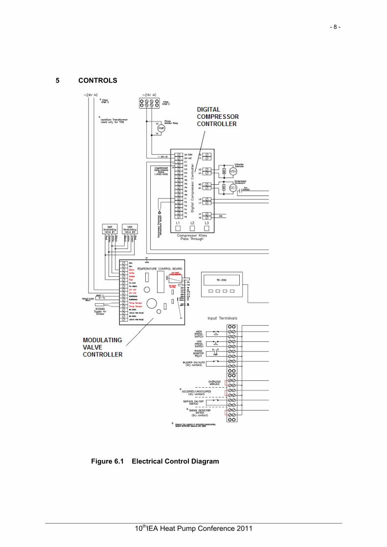
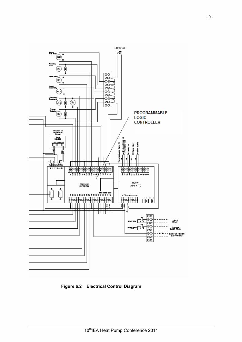
5 CONTROLS
Figure 6.1 Electrical Control Diagram
- 8 -
10thIEA Heat Pump Conference 2011
- 9 -
Figure 6.2 Electrical Control Diagram
- 9 -
10thIEA Heat Pump Conference 2011
- 10 -
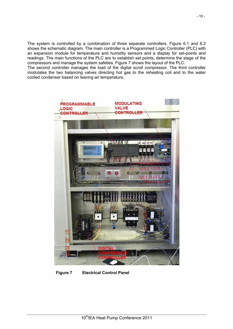
The system is controlled by a combination of three separate controllers. Figure 6.1 and 6.2 shows the schematic diagram. The main controller is a Programmed Logic Controller (PLC) with an expansion module for temperature and humidity sensors and a display for set-points and readings. The main functions of the PLC are to establish set points, determine the stage of the compressors and manage the system safeties. Figure 7 shows the layout of the PLC. The second controller manages the load of the digital scroll compressor. The third controller modulates the two balancing valves directing hot gas to the reheating coil and to the water cooled condenser based on leaving air temperature.
Figure 7 Electrical Control Panel
- 10 -
10thIEA Heat Pump Conference 2011
- 11 -
6 CONCLUSIONS The DOAS Heat Pump with variable refrigerant flow has been functionally proven as a solid concept which brings savings in operation for that important segment of HVAC equipments. The energy saving model for this type of equipment has to be further developed based on a daily and monthly load in concordance with the site's potential humidity and temperature variations. Anticipated performance leads to 32 - 38% reduction in energy consumption. Given the goal of maximum reduction of operation costs, the DOAS concept should include a Total Energy Recovery (TER) device. For a more flexible air supply rate, a variable air flow air mover device is required. REFERENCES ASHRAE 2009. "ASHRAE Handbook-Fundamentals," Chapter 14 and 25, American Society of Heating, Refrigerating, and Air-Conditioning Engineers, Inc., Atlanta. Dieckmann, J., K. Roth, and J. Brodrick. 2007. "Emerging Technologies: Dedicated Outdoor Air Systems Revisited," ASHRAE Journal 49(12). Doctor, T. R. 2009. "Variable Refrigerant Volume Technology for DX-DOAS Applications," ASHRAE Annual Conference, Louisville KY, Seminar 44. Milliken, H. 2008. "Rating DX-DOAS Equipment," ASHRAE IAQ Applications 9(2). Mumma, S. A. 2003. "Decoupling OA and Space Thermal Control." ASHRAE IAQ Applications 4(1):12-15.
- 11 -
10thIEA Heat Pump Conference 2011