doc n° - alpha magnetic spectrometer · 6 ssp 52000 -eia-erp february 2001 a express rack...
TRANSCRIPT


Doc N°: ACP-RP-CGS-002
ACOP Issue: 1 Date: Jan. 2005
Operational Analysis Report
Page 2 of 29
CHANGE RECORD
ISSUE
DATE
CHANGE AUTHORITY
REASON FOR CHANGE AND AFFECTED SECTIONS
1 Jan.05 First Edition

Doc N°: ACP-RP-CGS-002
ACOP Issue: 1 Date: Jan. 2005
Operational Analysis Report
Page 3 of 29
LIST OF VALID PAGES
PAGE
ISSUE
PAGE
ISSUE
PAGE
ISSUE
PAGE
ISSUE
PAGE
ISSUE
1 - 29 1

Doc N°: ACP-RP-CGS-002
ACOP Issue: 1 Date: Jan. 2005
Operational Analysis Report
Page 4 of 29
TABLE OF CONTENTS
1. SCOPE AND INTRODUCTION __________________________________________________________________ 7
1.1 PURPOSE OF THE DOCUMENT ______________________________________________________________ 7
1.2 DEFINITIONS AND ACRONYMS _____________________________________________________________ 9
1.3 Documents ______________________________________________________________________________ 13 1.3.1 Applicable documents__________________________________________________________________ 13 1.3.2 Reference documents __________________________________________________________________ 14
2. General description___________________________________________________________________________ 15
2.1 DESCRIPTION OF ACOP __________________________________________________________________ 15
2.2 Function and purpose of ACOP in the FRAME of the AMS-02 project__________________________________ 15
2.3 Hardware ARCHITECTURE_________________________________________________________________ 17 2.3.1 Electrical and Optical InterfaCES __________________________________________________________ 17 2.3.2 ACOP Hardware ARCHITECTURE ________________________________________________________ 18
2.4 ACOP SOFtWARE _______________________________________________________________________ 20
2.5 Mechanical DEsign _______________________________________________________________________ 21 2.5.1 lay out of connectors and lcd (on front panel) ________________________________________________ 22 2.5.2 INTERNAL BOARDS layout _____________________________________________________________ 23 2.5.3 airflow interface_______________________________________________________________________ 24 2.5.4 thermal design________________________________________________________________________ 24
3. Flight OPeration phases _______________________________________________________________________ 26
3.1 launch phase ____________________________________________________________________________ 26
3.2 Flight phase _____________________________________________________________________________ 26 3.2.1 Installation of ACOP inside An US-LAB ISPR ________________________________________________ 26 3.2.2 External Cable Installation _______________________________________________________________ 26 3.2.3 ACOP POWER ON ____________________________________________________________________ 26 3.2.4 ACOP Power Off ______________________________________________________________________ 26 3.2.5 HARD Drive Disks installation and Exchange ________________________________________________ 26 3.2.6 Crew Interfaces _______________________________________________________________________ 27 3.2.7 Operative Modes _____________________________________________________________________ 27 3.2.8 CPCI Boards and Power Board Substitution__________________________________________________ 28 3.2.9 SoftWare upgrade_____________________________________________________________________ 28 3.2.10 AIR FILTERs EXCHANGE/CLEANIng _____________________________________________________ 28
3.3 RETURN TO Ground ______________________________________________________________________ 29

Doc N°: ACP-RP-CGS-002
ACOP Issue: 1 Date: Jan. 2005
Operational Analysis Report
Page 5 of 29
LIST OF TABLES TAB. 1-1 APPLICABLE DOCUMENTS..............................................................................................................................................................13 TAB. 1-2 REFERENCE DOCUMENTS.................................................................................................................................................................14

Doc N°: ACP-RP-CGS-002
ACOP Issue: 1 Date: Jan. 2005
Operational Analysis Report
Page 6 of 29
LIST OF FIGURES FIG.1-1US-LAB.....................................................................................................................................................................................................7 FIG.1-2 EXAMPLE OF EXPRESS RACK................................................................................................................................................................8 FIG.2-1 ACOP RELATIONSHIP TO ISS AVIONICS AND AMS-02 ................................................................................................................17 FIG. 2-2 ACOP ELECTRICAL BLOCK DIAGRAM ............................................................................................................................................18 FIG.2-3 LOCATION OF ACOP INSIDE A EXPRESS RACK ...............................................................................................................................21 FIG.2-4 FRONT PANEL LAYOUT ......................................................................................................................................................................22 FIG.2-5 MECHANICAL AND ELECTRICAL MAIN PARTS OF ACOP ............................................................................................................23 FIG.2-6 HDD LOCATION IN ACOP ..................................................................................................................................................................23 FIG.2-7REAR SIDE OF ACOP.............................................................................................................................................................................24 FIG.2-8 THERMAL DESIGN (FRONT VIEW)......................................................................................................................................................24 FIG.2-9 COOLING AIRFLOW ..............................................................................................................................................................................25 FIG.3-1 OPERATION MODES STATE DIAGRAM ............................................................................................................................................28

Doc N°: ACP-RP-CGS-002
ACOP Issue: 1 Date: Jan. 2005
Operational Analysis Report
Page 7 of 29
1. SCOPE AND INTRODUCTION
1.1 PURPOSE OF THE DOCUMENT
The purpose of this document is to provide documentation and data for flight operation and maintenance of the AMS-02 Crew Operations Post (ACOP). The ACOP System is intended to fly on the International Space Station (ISS) as a payload installed into a ISPR on the NASA laboratory. The main objective of ACOP is to provide an ISS Internal Facility capable of supporting AMS-02 experiment, performing the recording of Science data. In particular, ACOP shall allow a more flexible and efficient use of ISS TM downlink, providing a temporary backup of data generated by AMS-02 and preventing, in this way, possible losses of valuable data. In addition, ACOP is the operational interface to on board crew in order to control and monitor AMS-02 inside from ISS and to permit files and SW upload into the supported payloads. ACOP system shall be installed in the U.S. Laboratory Module, on the ISS, in one EXPRESS rack (see, for reference,Fig.1-1 US-LAB).
Fig.1-1 US-LAB
The standard configuration of an EXPRESS Rack is commonly known as 8/2. This means that it can accommodate eight ISS locker/Middeck Locker (MDL) and two International Subrack Interface Standard (ISIS), as shown n Fig.1-2. On-Board Spare parts shall be accommodated in a standard soft bag.

Doc N°: ACP-RP-CGS-002
ACOP Issue: 1 Date: Jan. 2005
Operational Analysis Report
Page 8 of 29
Fig.1-2 Example of Express Rack

Doc N°: ACP-RP-CGS-002
ACOP Issue: 1 Date: Jan. 2005
Operational Analysis Report
Page 9 of 29
1.2 DEFINITIONS AND ACRONYMS
A AAA Avionics Air Assembly ABCL As-Built Configuration data List ACOP AMS-02 Crew Operation Post ACOP-SW ACOP Flight Software ADP Acceptance Data Package AMS-02 Alpha Magnetic Spectrometer 02 APS Automatic Payload Switch AR Acceptance Review ASI Agenzia Spaziale Italiana (Italian Space Agency) ATP Authorization To Proceed B BC Bus Coupler BDC Baseline Data Collection BDCM Baseline Data Collection Model C CAD Computer Aided Design CCB Configuration Control Board CCSDS Consultative Committee on Space Data Standards (standard format for data transmission) C&DH Command & Data Handling CDR Critical Design Review CGS Carlo Gavazzi Space CI Configuration Item CIDL Configuration Item data List CM Configuration Management COTS Commercial Off The Shelf cPCI CompactPCI (Euro Card sized standard interface to the PCI) CSCI Computer Software Configuration Item CSIST Chung Shan Institute of Science and Technology D DCL Declared Components List DIL Deliverable Items List DIO Digital Input / Output DML Declared Materials List DMPL Declared Mechanical Parts List DPL Declared Processes List DRB Delivery Review Board DRD Document Requirements Description E EEE Electrical, Electronic & Electromechanical EGSE Electrical Ground Support Equipment EM Engineering Model ER EXPRESS Rack ERL EXPRESS Rack Laptop ERLC EXPRESS Rack Laptop Computer ERLS EXPRESS Rack Laptop Software EMC Electro-Magnetic Compatibility ESA European Space Agency EXPRESS EXpedite the PRocessing of Experiments to Space Station F

Doc N°: ACP-RP-CGS-002
ACOP Issue: 1 Date: Jan. 2005
Operational Analysis Report
Page 10 of 29
FEM Finite Element Model FFMAR Final Flight Model Acceptance Review FLASH Rewriteable persistent computer memory FM Flight Model FMECA Failure Modes, Effects & Criticalities Analysis FPGA Field Programmable Gate Array FSM Flight Spare Model G GIDEP Government Industry Data Exchange Program GSE Ground Support Equipment H HCOR HRDL Communications Outage Recorder HD Hard Drive HDD Hard Disk Drive HRDL High Rate Data Link HRFM High Rate Frame Multiplexer HW Hardware I ICD Interface Control Document I/F Interface IRD Interface Requirements Document ISPR International Space-station Payload Rack ISS International Space Station J JSC Johnson Space Center K KIP Key Inspection Point KSC Kennedy Space Center KU-Band High rate space to ground radio link L LAN Local Area Network LCD Liquid Crystal Display LFM Low Fidelity Model LRDL Low Rate Data Link M MDL Mid-Deck Locker MGSE Mechanical Ground Support Equipment MIP Mandatory Inspection Point MMI Man Machine Interface MPLM Multi-Purpose Logistic Module MRDL Medium Rate Data Link N NA Not Applicable NASA National Aeronautics and Space Administration NCR Non Conformance Report NDI Non Destructive Inspection NRB Non-conformance Review Board NSTS National Space Transportation System (Shuttle) O

Doc N°: ACP-RP-CGS-002
ACOP Issue: 1 Date: Jan. 2005
Operational Analysis Report
Page 11 of 29
OLED Organic Light-Emitting Diode ORU Orbital Replacement Unit P PA Product Assurance PCB Printed Circuit Board PCI Peripheral Component Interconnect (personal computer bus) PCS Personal Computer System PDR Preliminary Design Review PEHB Payload Ethernet Hub Bridge PEHG Payload Ethernet Hub Gateway PFMAR Preliminary Flight Model Acceptance Review PLMDM Payload Multiplexer De-Multiplexer PMC PCI (Peripheral Component Interconnect) Mezzanine Card PMP Parts, Materials & Processes PROM Programmable Read Only Memory PS Power Supply Q QM Qualification Model R RFA Request For Approval RFD Request For Deviation RFW Request For Waiver RIC Rack Interface Controller ROD Review Of Design ROM Read Only Memory RX Reception S SATA Serial Advanced Transfer Architecture (disk interface) S-Band Space to ground radio link SBC Single Board Computer SC MDM Station Control Multiplexer De-Multiplexer ScS Suitcase Simulator SDD Solid-state Disk Drive SIM Similarity Assessment SIO Serial Input Output SOW Statement Of Work SPF Single Point Failure SRD Software Requirements Document STS Space Transportation System (Shuttle) SW Software T TBC To Be Confirmed TBD To Be Defined TBDCM Training & Baseline Data Collection Model TBDCMAR TBDCM Acceptance Review TBP To Be Provided TCP/IP Transmission Control Protocol / Internet Protocol TFT Thin Film Transistor TM Telemetry TRB Test Review Board TRR Test Readiness Review TRM Training Model TX Transmission

Doc N°: ACP-RP-CGS-002
ACOP Issue: 1 Date: Jan. 2005
Operational Analysis Report
Page 12 of 29
U UIP Utility Interface Panel UMA Universal Mating Assembly USB Universal Serial Bus

Doc N°: ACP-RP-CGS-002
ACOP Issue: 1 Date: Jan. 2005
Operational Analysis Report
Page 13 of 29
1.3 DOCUMENTS
1.3.1 APPLICABLE DOCUMENTS
AD Doc. Number Issue / Date Rev. Title / Applicability
1 SSP 52000-IDD-ERP D / 6.08.03 EXpedite the PRocessing of Experiments to Space Station (EXPRESS) Rack Payloads Interface Definition Document
2 NSTS/ISS 13830 C / 01.12.1996 Implementation Procedures for Payloads System Safety Requirements – For Payloads Using the STS & ISS.
3 JSC 26493 17.02.1995 Guidelines for the preparation of payload flight safety data packages and hazard reports.
4 SSP 50004 April 1994 Ground Support Equipment Design requirements
5 SSP-52000-PDS March 1999 B Payload Data Set Blank Book
6 SSP 52000-EIA-ERP February 2001 A Express Rack Integration Agreement blank book for Express Rack payload
7 GD-PL-CGS-001 3 / 17.03.99 Product Assurance & Rams Plan
8 SSP 52000 PAH ERP November 1997 Payload Accommodation Handbook for EXPRESS Rack
9 SSP 50184 D / February 1996 Physical Media, Physical Signaling & link-level Protocol Specification for ensuring Interoperability of High Rate Data Link Stations on the International Space Program
10 SSP 52050 D / 08.06.01 S/W Interface Control Document for ISPR ***ONLY FOR HRDL, SECTION 3.4 ***
11 ECSS-E-40 A / April 1999 13 Software Engineering Standard
12 AMS02-CAT-ICD-R04 29.08.2003 04 AMS02 Command and Telemetry Interface Control document. Section AMS-ACOP Interfaces
13 SSP 52000-PVP-ERP Sept. 18, 2002 D Generic Payload Verification Plan EXpedite the PRocessing of Experiments to Space Station (EXPRESS) Rack Payloads
14 NSTS 1700.7B Rev. B Change Packet 8 / 22.08.00
Safety Policy and Requirements for Payloads using the STS
15 NSTS 1700.7B Addendum
Rev. B Change Packet 1 / 01.09.00
Safety Policy and Requirements for Payloads using the International Space Station
16 SSP 52005 Dec. 10, 1998 Payload Flight equipment requirements and guidelines for safety critical structures
17 NSTS 18798B Change Packet 7 10.00
Interpretation of NSTS Payload Safety Requirements
18 MSFC-HDBK-527 15.11.86 E Materials selection list for space hardware systems Materials selection list data
19 GD-PL-CGS-002 1 / 12.02.99 CADM Plan
20 GD-PL-CGS-004 2 / 07.04.03 SW Product Assurance Plan
21 GD-PL-CGS-005 2 / 09.05.03 SW CADM Plan
Tab. 1-1 Applicable Documents

Doc N°: ACP-RP-CGS-002
ACOP Issue: 1 Date: Jan. 2005
Operational Analysis Report
Page 14 of 29
1.3.2 REFERENCE DOCUMENTS
Tab.
RD Doc. Number Issue / Date Rev. Title
1 GPQ-MAN-02 1 Commercial, Aviation and Military (CAM) Equipment Evaluation Guidelines for ISS Payloads Use
2 BSSC (96)2 1 / May 96 Guide to applying the ESA software engineering standards to small software projects
3 GPQ-MAN-01 2 / December 98 Documentation Standard for ESA Microgravity Projects
4 MS-ESA-RQ-108 1 / 28 Sept. 2000 Documentation Requirements For Small And Medium Sized MSM Projects
5 PSS-05 Software Engineering Standards
6 GPQ-010 1 / May 95 A Product Assurance Requirements for ESA Microgravity Payload. Including CN 01.
7 GPQ-010-PSA-101 1 Safety and Material Requirements for ESA Microgravity Payloads
8 GPQ-010-PSA-102 1 Reliability and Maintainability for ESA Microgravity Facilities (ISSA). Including CN 01
9 ESA PSS-01-301 2 / April 1992 De-rating requirements applicable to electronic, electrical and electro-mechanical components for ESA space systems
10 ECSS-Q-60-11A 1 / 7 Sept. 2004 De-rating and End-of-life Parameter Drifts – EEE Components
11 ACP-RP-CGS-003 1 / Jan 05 ACOP Design Report
Tab. 1-2 Reference Documents
Doc N°: ACP-RP-CGS-002
ACOP Issue: 1 Date: Jan. 2005
Operational Analysis Report
Page 15 of 29
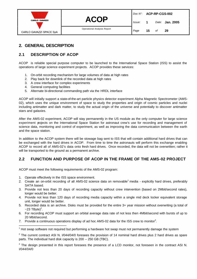
2. GENERAL DESCRIPTION
2.1 DESCRIPTION OF ACOP
ACOP is reliable special purpose computer to be launched to the International Space Station (ISS) to assist the operations of large science experiment projects. ACOP provides these services:
1. On-orbit recording mechanism for large volumes of data at high rates 2. Play back for downlink of the recorded data at high rates 3. A crew interface for complex experiments 4. General computing facilities 5. Alternate bi-directional commanding path via the HRDL interface
ACOP will initially support a state-of-the-art particle physics detector experiment Alpha Magnetic Spectrometer (AMS-02), which uses the unique environment of space to study the properties and origin of cosmic particles and nuclei including antimatter and dark matter, to study the actual origin of the universe and potentially to discover antimatter stars and galaxies. After the AMS-02 experiment, ACOP will stay permanently in the US module as the only computer for large science experiment projects on the International Space Station for astronaut crew’s use for recording and management of science data, monitoring and control of experiment, as well as improving the data communication between the earth and the space station. In addition to the ACOP system there will be stowage bag sent to ISS that will contain additional hard drives that can be exchanged with the hard drives in ACOP. From time to time the astronauts will perform this exchange enabling ACOP to record all of AMS-02’s data onto fresh hard drives. Once recorded, the data will not be overwritten; rather it will be transported to the ground as a permanent archive.
2.2 FUNCTION AND PURPOSE OF ACOP IN THE FRAME OF THE AMS-02 PROJECT
ACOP must meet the following requirements of the AMS-02 program:
1. Operate effectively in the ISS space environment. 2. Create an on-orbit recording of all AMS-02 science data on removable1 media - explicitly hard drives, preferably
SATA based. 3. Provide not less than 20 days of recording capacity without crew intervention (based on 2Mbit/second rates),
longer would be better. 4. Provide not less than 120 days of recording media capacity within a single mid deck locker equivalent storage
unit, longer would be better. 5. Recorded data is an archive. Disks must be provided for the entire 3+ year mission without overwriting (a total of
~23 TByte)2. 6. For recording ACOP must support an orbital average data rate of not less then 4Mbit/second with bursts of up to
20 Mbit/second. 7. Provide a continuous operations display of ad hoc AMS-02 data for the ISS crew to monitor3. 1 Hot swap software not required but performing a hardware hot swap must not permanently damage the system
2 The current contract ASI N. I/044/04/0 foresees the provision of 14 nominal hard drives plus 2 hard drives as spare parts. The individual hard disk capacity is 200 – 250 GB (TBC).
3 The design presented in this report foresees the presence of a LCD monitor, not foreseen in the contract ASI N. I/044/04/0

Doc N°: ACP-RP-CGS-002
ACOP Issue: 1 Date: Jan. 2005
Operational Analysis Report
Page 16 of 29
8. Provide a continuous means for the ISS crew to issue ad hoc predefined commands without external equipment4. 9. Provide, as needed, an exhaustive diagnostic, monitoring and operations environment via the EXPRESS laptop
computer. 10. Support the playback of recorded data to ground systems at selectable data rates up to at least 20Mbits/second
sustained while simultaneously recording at prescribed rates. 11. Support ACOP to AMS-02 commanding at selectable data rates up to at least 20Mbits/second sustained (No
requirement for simultaneous recording or playback operations at higher rates.) 12. Support an alternate AMS-02 ground commanding and housekeeping report path via the HRDL interface. 13. CompactPCI based. Preferably 6U form factor. 14. Crew serviceable for upgrades and repairs - hardware and software. 15. Provide for upgrades and expansion to ACOP using COTS subsystems. 16. Provide support of ISS system upgrades (100bt MRDL follow on systems)5. 17. ACOP will be housed in an EXPRESS Rack Locker. 18. The mass budget for ACOP is 35.5 kg for the EXPRESS Rack Locker and 35.5 kg for the soft stowage bag. 19. The power allocated to ACOP is 200 watts6
4 The design presented in this report foresees the presence of a LCD monitor, not foreseen in the contract ASI N. I/044/04/0
5 Not foreseen in the contract ASI N. I/044/04/0
6 See Section 5.6 of RD11for the actual power budget
Doc N°: ACP-RP-CGS-002
ACOP Issue: 1 Date: Jan. 2005
Operational Analysis Report
Page 17 of 29
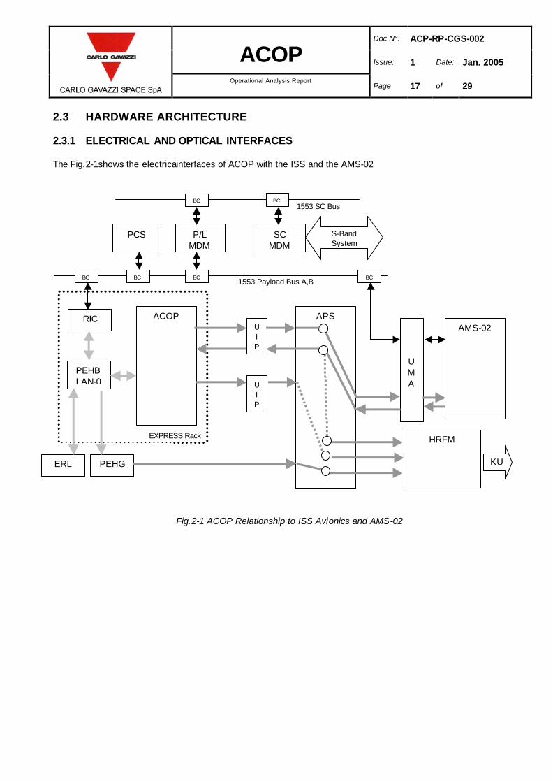
2.3 HARDWARE ARCHITECTURE
2.3.1 ELECTRICAL AND OPTICAL INTERFACES
The Fig.2-1shows the electricainterfaces of ACOP with the ISS and the AMS-02
Fig.2-1 ACOP Relationship to ISS Avionics and AMS-02
APS RIC
PEHB LAN-0
PEHG
U
I
P
SC MDM
P/L MDM
BC
ERL
PCS
AMS-02
UMA U
I
P
ACOP
BC BC BC
EXPRESS Rack
1553 Payload Bus A,B
S-Band
System
HRFM
BC BC 1553 SC Bus
KU
Doc N°: ACP-RP-CGS-002
ACOP Issue: 1 Date: Jan. 2005
Operational Analysis Report
Page 18 of 29
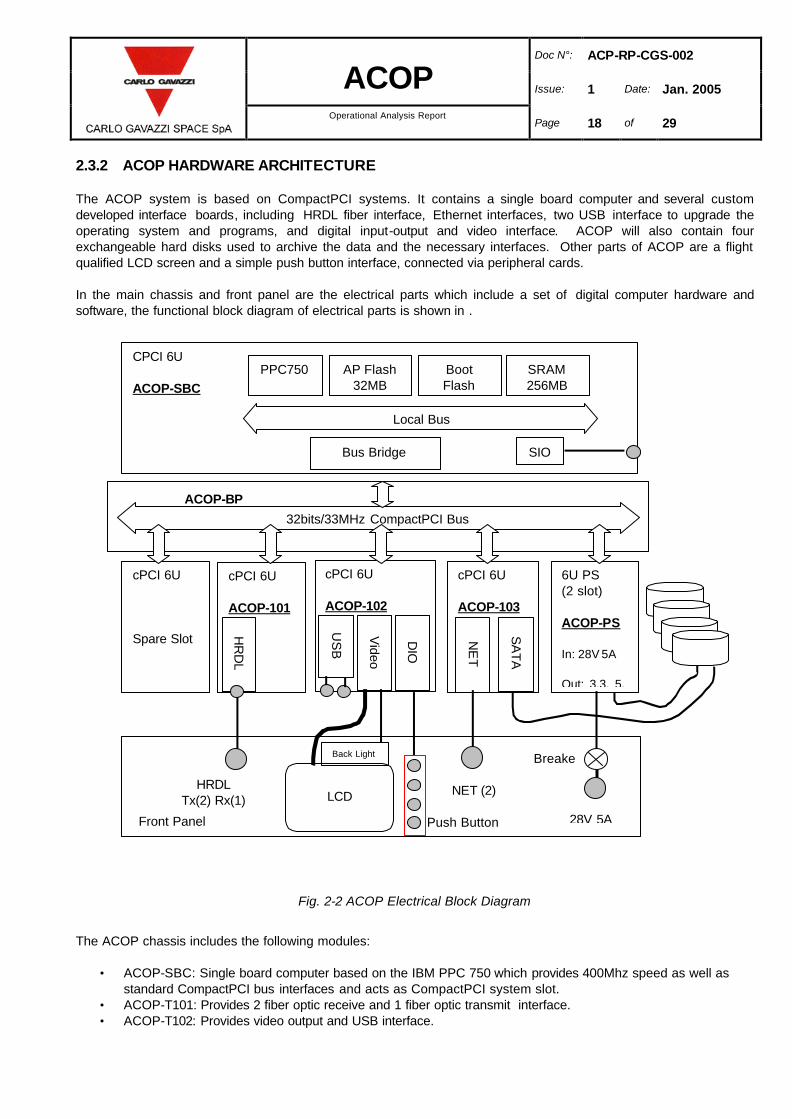
2.3.2 ACOP HARDWARE ARCHITECTURE
The ACOP system is based on CompactPCI systems. It contains a single board computer and several custom developed interface boards, including HRDL fiber interface, Ethernet interfaces, two USB interface to upgrade the operating system and programs, and digital input-output and video interface. ACOP will also contain four exchangeable hard disks used to archive the data and the necessary interfaces. Other parts of ACOP are a flight qualified LCD screen and a simple push button interface, connected via peripheral cards. In the main chassis and front panel are the electrical parts which include a set of digital computer hardware and software, the functional block diagram of electrical parts is shown in .
Fig. 2-2 ACOP Electrical Block Diagram
The ACOP chassis includes the following modules:
• ACOP-SBC: Single board computer based on the IBM PPC 750 which provides 400Mhz speed as well as standard CompactPCI bus interfaces and acts as CompactPCI system slot.
• ACOP-T101: Provides 2 fiber optic receive and 1 fiber optic transmit interface. • ACOP-T102: Provides video output and USB interface.
32bits/33MHz CompactPCI Bus
cPCI 6U Spare Slot
cPCI 6U ACOP-103
SA
TA
NE
T
cPCI 6U ACOP-101
cPCI 6U ACOP-102
Vid
eo
DIO
6U PS (2 slot) ACOP-PS In: 28V 5A Out: 3.3, 5,
Front Panel
NET (2)
LCD
Back Light
CPCI 6U ACOP-SBC
Local Bus
SIO Bus Bridge
PPC750 AP Flash 32MB
Boot Flash
SRAM 256MB
HR
DL
HRDL Tx(2) Rx(1)
US
B
28V 5A
ACOP-BP
Breake
Push Button
Doc N°: ACP-RP-CGS-002
ACOP Issue: 1 Date: Jan. 2005
Operational Analysis Report
Page 19 of 29
• ACOP-T103: Provides 2 Ethernet ports and 4 SATA ports. • ACOP-T104: spare for future expansion purpose • ACOP-PS: Double height power supply. • 4 hot swappable HDD (hard Disk Drive)
The ACOP front panel will be mounted with
• Four Momentary Press Buttons • One Circuit Breaker On/Off Switch • One HRDL Connector • One Power Connector • One MRDL Connector with 10/100 base Ethernet
During the engineering development stage, the I/O configuration will be tailored with PMC mezzanine modules and all modules integrate in an industry standard CompactPCI backplane. The design is scaleable and expandable, with a clear and built-in path for technology upgrades and insertion. A well-defined avionics Application Programming Architecture abstracts the application software from the underlying hardware, affording system evolution to ever-increasing performance standards, while effectively managing obsolescence. The Ethernet interface and USB interface can also supports software development and system maintenance during development.

Doc N°: ACP-RP-CGS-002
ACOP Issue: 1 Date: Jan. 2005
Operational Analysis Report
Page 20 of 29
2.4 ACOP SOFTWARE
ACOP-SW is the entire body of embedded software running on the ACOP hardware. ACOP-SW consists of three components:
• ACOP-SYS-SW providing low level functionality, • ACOP-APP-SW providing the mission explicit application software functions on the ACOP hardware, • ACOP-ERL-SW software developed by the ACOP project but which executes on the EXPRESS Rack Laptop.
The ACOP-SYS-SW consists of eCos, a open source embedded operating system and LINUX Operating System kernel ( version 2.6). Drivers under LINUX OS for all the cPCI boards and the storage devices will be used. The ACOP-APP-SW will be based on a cooperative multitasking system which moves messages among tasks. Tasks are used to provide: interfaces to external devices, functions (such as recording), data management (telemetry queue manager), and automation of functions (master control task). The [RD3] contains a detailed description of the ACOP Software.
Doc N°: ACP-RP-CGS-002
ACOP Issue: 1 Date: Jan. 2005
Operational Analysis Report
Page 21 of 29
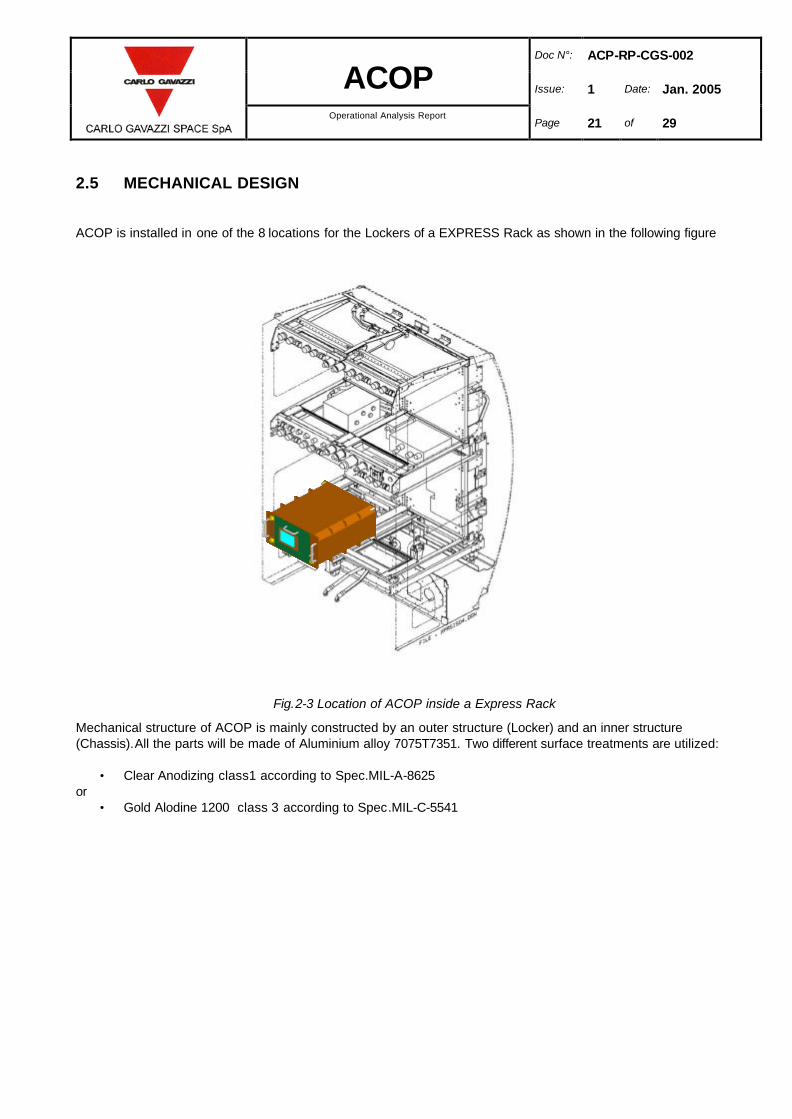
2.5 MECHANICAL DESIGN
ACOP is installed in one of the 8 locations for the Lockers of a EXPRESS Rack as shown in the following figure
Fig.2-3 Location of ACOP inside a Express Rack
Mechanical structure of ACOP is mainly constructed by an outer structure (Locker) and an inner structure (Chassis).All the parts will be made of Aluminium alloy 7075T7351. Two different surface treatments are utilized:
• Clear Anodizing class1 according to Spec.MIL-A-8625 or
• Gold Alodine 1200 class 3 according to Spec.MIL-C-5541

Doc N°: ACP-RP-CGS-002
ACOP Issue: 1 Date: Jan. 2005
Operational Analysis Report
Page 22 of 29
2.5.1 LAY OUT OF CONNECTORS AND LCD (ON FRONT PANEL)
The Fig.2-4 shows the ACOP front panel: on the fixed part of the Front Panel three connectors ( TBC) will be located for Power ( 28 Vdc) , Data ( Ethernet) and High Rate Data Link Interface. Four buttons will be provided to allow control and monitoring of ACOP by the crew, the buttons will allow the crew to navigate into the menus displayed on the LCD. Also a Circuit Breaker will be installed. Two handles will also be installed to move, install and remove the ACOP. A LCD will be mounted ( TBC) on a movable part of the front panel ( LCD front panel), the movable part will be attached to the fixed front panel by means of a friction hinge placed on the bottom side of Fig.2-5 and held closed by a magnetic catch. The movable part show be able to be secured in the closed position by two ¼ Turn Fastener/Locker placed on the corners of the top side. Indication by labels of the closed and open position will be provided.
Fig.2-4 Front Panel Layout
Circuit Breaker
Power connector
LCD
Front panel buttons
HRDL Connector
Data connector
Circuit Breaker
Power connector
LCD
Front panel buttons
HRDL Connector
Data connector

Doc N°: ACP-RP-CGS-002
ACOP Issue: 1 Date: Jan. 2005
Operational Analysis Report
Page 23 of 29
2.5.2 INTERNAL BOARDS LAYOUT
Fig.2-5 shows the internal disposition of the ACOP boards as it will be seen by the crew when the LCD front panel is opened. The opening of the LCD front panel will be actuated by the crew after powering down the ACOP using the front panel switch. The upper part will be occupied by 4 HDDs that are mounted on four dedicated caddies. The caddies will be fixed to the chassis by means of card retainer ( provided with lever arm to minimize the crew effort to replace them). The power and the data interface to the HDD is by means of a blind mate connector placed on the rear side of the HDD caddy , the usage of guiding pins to mate the connector placed on the rear backplane will be considered. The cPCI boards plus the Power board will be hosted in the low section of the chassis: also these boards will be fixed to the chassis by means of card retainer.
Fig.2-5 Mechanical and Electrical Main parts of ACOP
Fig.2-6 HDD location in ACOP
4 Hard Drives
5 Compact PCI Power Supply
Board
Chassis
Locker
4 Hard Drives
5 Compact PCI Power Supply
Board
Chassis
Locker
Relative connectors on back plane
Connector on
the rear side of H.D.
H.D. is directly plug in
or out and the pull -push force = 5 kg (26
pins D type)
Relative connectors on back plane
Connector on
the rear side of H.D.
H.D. is directly plug in
or out and the pull -push force = 5 kg (26
pins D type)
Relative connectors on back plane
Connector on
the rear side of H.D.
H.D. is directly plug in
or out and the pull -push force = 5 kg (26
pins D type)

Doc N°: ACP-RP-CGS-002
ACOP Issue: 1 Date: Jan. 2005
Operational Analysis Report
Page 24 of 29
2.5.3 AIRFLOW INTERFACE
The ACOP will be cooled by airflow via Avionics Air Assembly (AAA) that provide fresh air blowing in and out through the holes on back plate of the Rack. The current baseline does not foresee to insert additional fans inside the ACOP locker to reinforce the airflow. Screen/grids will be mounted on the air inlet and outlet and designed in order to be easy to replace.
Fig.2-7 Rear side of ACOP
2.5.4 THERMAL DESIGN
Heat dissipation of hard disk drives and compact PCI boards will be conducted to the fins (wall) by conduction transfer. Airflow (via Avionics Air Assembly) will blow through the fins and remove the heat by forced convection (see Fig.2-8 and Fig.2-9). Also the LCD power will be removed by the AAA airflow.
Fig.2-8 Thermal design (Front view)
Heat Dissipation FinsChassis
Air duct
Heat Dissipation FinsChassis
Air duct
Heat Dissipation FinsChassis
Air duct
CABLE

Doc N°: ACP-RP-CGS-002
ACOP Issue: 1 Date: Jan. 2005
Operational Analysis Report
Page 25 of 29
Fig.2-9 Cooling airflow
Air Inlet
from AAA
Air Outlet
Airflow passes
through
front space
Air Duct

Doc N°: ACP-RP-CGS-002
ACOP Issue: 1 Date: Jan. 2005
Operational Analysis Report
Page 26 of 29
3. FLIGHT OPERATION PHASES
The Flight operation are here below listed. All the ACOP Flight Operations are safe in accordance with NSTS 182798B Interpretation Letter MA-00-038
3.1 LAUNCH PHASE
Nominally ACOP will be launched installed in a transportation rack within the MPLM (compatibility with other transportation modes as aft flight deck and ATV will be investigated if necessary). ACOP is not powered and no hard drives are installed during assent. Hard drives, and other spare parts, are carried in a soft side stowage bag.
3.2 FLIGHT PHASE
3.2.1 INSTALLATION OF ACOP INSIDE AN US-LAB ISPR
The ACOP will be installed into a US-LAB ISPR by the crew by securing the four captive bolts in the rear of ACOP to the EXPRES rack back plate. The launch locks on the front panel will be released and four hard drives installed.
3.2.2 EXTERNAL CABLE INSTALLATION
The crew has to install the external cables that connect ACOP to the ISS: Power cable ( to be connected to Jx of ACOP front panel see RD4 ) , HRDL cable ( to be connected to Jy of ACOP front panel see RD4) and Data cable (to be connected to Jz of ACOP front panel see RD4)
3.2.3 ACOP POWER ON
Other then brief (less then 8 hours periods) of ISS low power modes and during hard drive exchange ACOP will be powered on. The Power On phase consists of putting ACOP’s front panel circuit breaker in the “on” and verifying on the display that the booting phase of ACOP has finished successfully and ACOP is in the cold start mode (see below). ACOP’s operational mode can then be selected by interaction with the command interfaces (either by the crew or ground.)
3.2.4 ACOP POWER OFF
Nominally ACOP is informed that it is being powered down. When so instructed it enters the Active Idle mode. Once this condition has been verified ACOP can be switched off.
3.2.5 HARD DRIVE DISKS INSTALLATION AND EXCHANGE
The ISS crew will be in charge of installation and exchange of hard drives. The operation will be made with ACOP powered down. The crew has to:
1. Retrieve the appropriate ACOP storage bag. 2. Power down ACOP per 3.2.4 above.

Doc N°: ACP-RP-CGS-002
ACOP Issue: 1 Date: Jan. 2005
Operational Analysis Report
Page 27 of 29
3. Open the LCD front panel by pulling the LCD front panel handle. The LCD font panel will remain in the open
position thanks to a friction hinge. 4. HDDs already installed are removed and returned to the stowage bag. 5. Fresh HDDs will be inserted in the four slots present inside the ACOP and fixed with the card retainer: lever
arm type card retainers will be used so no dedicated tools are required for this activity.. 6. The crew will log the disk serial numbers of disks removed and installed. 7. Restore power and resume operation per 3.2.3 above. 8. Re-stow the ACOP stowage bag.
3.2.6 CREW INTERFACES
The crew is provided two interfaces to ACOP. A simple automatic teller machine (ATM) style of soft labeled buttons is provided via the front panel LCD. Support is provided for key monitoring and operations functions for both ACOP and AMS-02 via this interface. This interface includes ACOP front panel controls for the LCD for backlighting and contrast. A second, more robust, interface is provided via the EXPRESS Rack Laptop (ERL) computer. It is anticipated that several graphical interfaces for both ACOP and AMS-02 will be developed for ERL.
3.2.7 OPERATIVE MODES
ACOP is primarily a ground operated system but can be crew commanded. ACOP will have the following principal operating modes:
• Powered off • Cold start • Software upgrade (a special function of cold start) • Warm start • Active idle • Active recording • Active playback • Active recording and playback
During any of the active modes ACOP can serve as a crew interface directing commands to AMS-02. During any of the states other then powered off ACOP will accept ground commands.
Doc N°: ACP-RP-CGS-002
ACOP Issue: 1 Date: Jan. 2005
Operational Analysis Report
Page 28 of 29
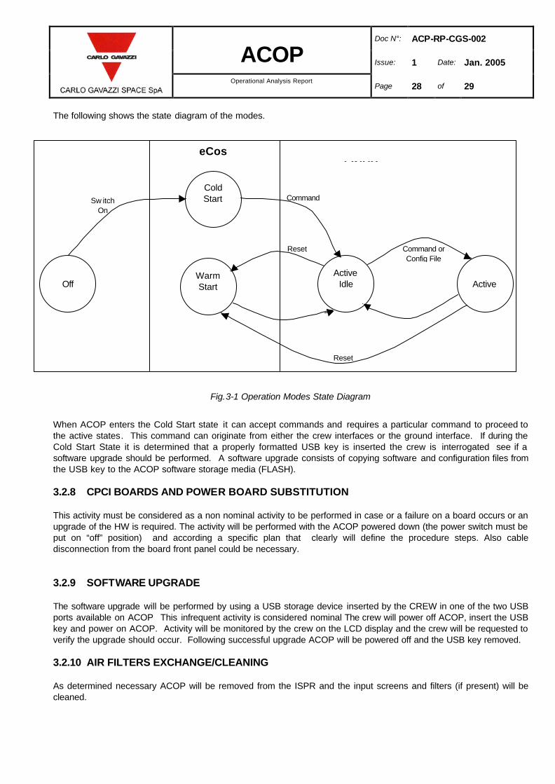
The following shows the state diagram of the modes.
Fig.3-1 Operation Modes State Diagram
When ACOP enters the Cold Start state it can accept commands and requires a particular command to proceed to the active states. This command can originate from either the crew interfaces or the ground interface. If during the Cold Start State it is determined that a properly formatted USB key is inserted the crew is interrogated see if a software upgrade should be performed. A software upgrade consists of copying software and configuration files from the USB key to the ACOP software storage media (FLASH).
3.2.8 CPCI BOARDS AND POWER BOARD SUBSTITUTION
This activity must be considered as a non nominal activity to be performed in case or a failure on a board occurs or an upgrade of the HW is required. The activity will be performed with the ACOP powered down (the power switch must be put on “off” position) and according a specific plan that clearly will define the procedure steps. Also cable disconnection from the board front panel could be necessary.
3.2.9 SOFTWARE UPGRADE
The software upgrade will be performed by using a USB storage device inserted by the CREW in one of the two USB ports available on ACOP This infrequent activity is considered nominal The crew will power off ACOP, insert the USB key and power on ACOP. Activity will be monitored by the crew on the LCD display and the crew will be requested to verify the upgrade should occur. Following successful upgrade ACOP will be powered off and the USB key removed.
3.2.10 AIR FILTERS EXCHANGE/CLEANING
As determined necessary ACOP will be removed from the ISPR and the input screens and filters (if present) will be cleaned.
Warm Start
Active
Cold Start
Off
Active Idle
Sw itch
On
Reset
Reset
Command or
Config File
Command
eCos LINUX

Doc N°: ACP-RP-CGS-002
ACOP Issue: 1 Date: Jan. 2005
Operational Analysis Report
Page 29 of 29
.
3.3 RETURN TO GROUND
The current baseline is that ACOP will not be returned to the ground.