docklight scripting v2.3 user manual 12/2019docklight scripting is network-enabled. instead of using...
TRANSCRIPT

Docklight Scripting V2.3 User Manual12/2019
Copyright 2019 Flachmann und Heggelbacher GbR

2
Docklight Scripting V2.3 User Manual 12/2019 Copyright 2019 Flachmann und Heggelbacher GbR
Table of Contents
1. Copyright 7
2. Introduction 9
2.1 Docklight - Overview .................................................................................................... 10
2.2 Docklight Scripting - Overview ..................................................................................... 10
2.3 Typical Applications ..................................................................................................... 11
2.4 System Requirements ................................................................................................... 12
3. User Interface 14
3.1 Main Window (Scripting) ............................................................................................. 15
3.2 Clipboard - Cut, Copy & Paste ..................................................................................... 16
3.3 Documentation Area .................................................................................................... 16
4. Features and Functions 18
4.1 How Serial Data Is Processed and Displayed .............................................................. 19
4.2 Editing and Managing Sequences ................................................................................ 19
5. Working with Docklight 21
5.1 Testing a Serial Device or a Protocol Implementation ............................................... 22
5.2 Simulating a Serial Device ............................................................................................ 23
5.3 Monitoring Serial Communications Between Two Devices ....................................... 25
5.4 Catching a Specific Sequence and Taking a Snapshot of the Communication ......... 27
5.5 Logging and Analyzing a Test ....................................................................................... 27
5.6 Checking for Sequences With Random Characters (Receive SequenceWildcards) ..................................................................................................................... 28
5.7 Saving and Loading Your Project Data, Script and Options ....................................... 31
6. Working with Docklight (Advanced) 33
6.1 Sending Commands With Parameters (Send Sequence Wildcards) .......................... 34
6.2 How to Increase the Processing Speed and Avoid "Input Buffer Overflow"Messages ....................................................................................................................... 35
6.3 How to Obtain Best Timing Accuracy .......................................................................... 36
6.4 Calculating and Validating Checksums ....................................................................... 36
6.5 Controlling and Monitoring RS232 Handshake Signals .............................................. 38
6.6 Creating and Detecting Inter-Character Delays .......................................................... 42
6.7 Setting and Detecting a "Break" State ........................................................................ 44
6.8 Testing a TCP Server Device (Scripting) ....................................................................... 45
6.9 Monitoring a Client/Server TCP Connection (Scripting) ............................................. 46
7. Examples and Tutorials 49

3
Docklight Scripting V2.3 User Manual 12/2019 Copyright 2019 Flachmann und Heggelbacher GbR
Table of Contents
7.1 Testing a Modem - Sample Project: ModemDiagnostics.ptp ..................................... 50
7.2 Reacting to a Receive Sequence - Sample Project: PingPong.ptp .............................. 51
7.3 Modbus RTU With CRC checksum - Sample Project: ModbusRtuCrc.ptp ................. 52
8. Examples and Tutorials (Scripting) 55
8.1 Automated Modem Testing - Sample Script: ModemScript.pts ................................ 56
8.2 Startup From Command Line - Sample Script: LogStartupScript.pts ......................... 59
8.3 Manipulating a RS232 Data Stream - Sample Script:CharacterManipulation.pts .......................................................................................... 60
8.4 TCP/IP Communications - Sample Projects PingPong_TCP_Server/Client.ptp ......... 61
9. Reference 62
9.1 Menu and Toolbar (Scripting) ...................................................................................... 63
9.2 Dialog: Edit Send Sequence ......................................................................................... 65
9.3 Dialog: Edit Receive Sequence ..................................................................................... 66
9.4 Dialog: Start Logging / Create Log File(s) .................................................................... 67
9.5 Dialog: Customize HTML Output ................................................................................. 68
9.6 Dialog: Find Sequence .................................................................................................. 69
9.7 Dialog: Send Sequence Parameter .............................................................................. 70
9.8 Dialog: Project Settings - Communication .................................................................. 70
9.9 Dialog: Project Settings - Flow Control ....................................................................... 74
9.10 Dialog: Project Settings - Communication Filter ......................................................... 74
9.11 Dialog: Options ............................................................................................................. 75
9.12 Dialog: Expert Options ................................................................................................. 76
9.13 Keyboard Console ........................................................................................................ 77
9.14 Checksum Specification ................................................................................................ 78
10. Reference (Scripting) 81
10.1 VBScript Basics .............................................................................................................. 82
10.1.1 Copyright Notice .................................................................................................... 83
10.1.2 Control Structures ................................................................................................. 8310.1.2.1 Decision Structures ....................................................................................................................... 83
10.1.2.2 Loop Structures ............................................................................................................................. 84
10.1.3 Variables, Arrays, Constants and Data Types ..................................................... 85
10.1.4 Operators ............................................................................................................... 87
10.1.5 Date/Time Functions ............................................................................................. 88
10.1.6 Miscellaneous ........................................................................................................ 90
10.2 Docklight Script Commands - The DL Object .............................................................. 91
10.2.1 Methods ................................................................................................................. 9210.2.1.1 AddComment ................................................................................................................................. 92
10.2.1.2 ClearCommWindows .................................................................................................................... 93
10.2.1.3 GetReceiveCounter ........................................................................................................................ 93

4
Docklight Scripting V2.3 User Manual 12/2019 Copyright 2019 Flachmann und Heggelbacher GbR
Table of Contents
10.2.1.4 GetDocklightTimeStamp ............................................................................................................... 94
10.2.1.5 OpenProject ................................................................................................................................... 95
10.2.1.6 Pause ............................................................................................................................................... 96
10.2.1.7 Quit ................................................................................................................................................. 96
10.2.1.8 ResetReceiveCounter .................................................................................................................... 97
10.2.1.9 SendSequence ................................................................................................................................ 98
10.2.1.10 StartCommunication .................................................................................................................. 100
10.2.1.11 StopCommunication ................................................................................................................... 100
10.2.1.12 StartLogging ................................................................................................................................. 100
10.2.1.13 StopLogging ................................................................................................................................. 102
10.2.1.14 WaitForSequence ........................................................................................................................ 103
10.2.2 Methods (Advanced) ........................................................................................... 10410.2.2.1 CalcChecksum .............................................................................................................................. 104
10.2.2.2 ConvertSequenceData ................................................................................................................ 107
10.2.2.3 GetChannelSettings .................................................................................................................... 109
10.2.2.4 GetChannelStatus ....................................................................................................................... 110
10.2.2.5 GetCommWindowData .............................................................................................................. 112
10.2.2.6 GetEnvironment .......................................................................................................................... 112
10.2.2.7 GetHandshakeSignals ................................................................................................................. 114
10.2.2.8 GetKeyState ................................................................................................................................. 115
10.2.2.9 GetReceiveComments ................................................................................................................ 116
10.2.2.10 InputBox2 ..................................................................................................................................... 116
10.2.2.11 LoadProgramOptions .................................................................................................................. 117
10.2.2.12 PlaybackLogFile ........................................................................................................................... 118
10.2.2.13 SaveProgramOptions .................................................................................................................. 119
10.2.2.14 SetChannelSettings ..................................................................................................................... 120
10.2.2.15 SetContentsFilter ........................................................................................................................ 124
10.2.2.16 SetHandshakeSignals .................................................................................................................. 125
10.2.2.17 SetUserOutput ............................................................................................................................. 125
10.2.2.18 SetWindowLayout ....................................................................................................................... 127
10.2.2.19 ShellRun ........................................................................................................................................ 127
10.2.2.20 UploadFile .................................................................................................................................... 130
10.2.3 Properties ............................................................................................................ 13110.2.3.1 NoOfSendSequences ................................................................................................................... 131
10.2.3.2 NoOfReceiveSequences .............................................................................................................. 131
10.3 OnSend / OnReceive Event Procedures .................................................................... 132
10.3.1 Sub DL_OnSend() - Send Sequence Data Manipulation .................................... 132
10.3.2 Sub DL_OnReceive() - Evaluating Receive Sequence Data ................................. 135
10.3.3 OnSend / OnReceive - Timing and Program Flow .............................................. 140
10.4 FileInput / FileOutput Objects for Reading and Writing Files ................................. 142
10.4.1 FileInput - Reading Files ...................................................................................... 142
10.4.2 FileOutput - Writing Files .................................................................................... 144
10.4.3 Multiple Input Files / Multiple Output Files ...................................................... 144
10.5 Side Channels - Using Multiple Data Connections ................................................... 145
10.5.1 OpenSideChannel / CloseSideChannel - Managing multiple channels ............ 145
10.5.2 DirectSend ............................................................................................................ 146
10.6 Debug Object / Script Debugging .............................................................................. 148
10.7 #include Directive ....................................................................................................... 149
5
Docklight Scripting V2.3 User Manual 12/2019 Copyright 2019 Flachmann und Heggelbacher GbR
Table of Contents
10.8 Command Line Syntax ................................................................................................ 150
10.9 Dialog: Customize / External Editor .......................................................................... 151
11. Support 153
11.1 Web Support and Troubleshooting ........................................................................... 154
11.2 E-Mail Support ............................................................................................................ 154
12. Appendix 155
12.1 ASCII Character Set Tables ......................................................................................... 156
12.2 Hot Keys ...................................................................................................................... 158
12.3 RS232 Connectors / Pinout ........................................................................................ 160
12.4 Standard RS232 Cables ............................................................................................... 161
12.5 Docklight Monitoring Cable RS232 SUB D9 ............................................................... 164
12.6 Docklight Tap .............................................................................................................. 165
12.7 Docklight Tap Pro / Tap 485 ...................................................................................... 166
13. Glossary / Terms Used 168
13.1 Action .......................................................................................................................... 169
13.2 Break ........................................................................................................................... 169
13.3 Character ..................................................................................................................... 169
13.4 CRC .............................................................................................................................. 169
13.5 DCE .............................................................................................................................. 170
13.6 DTE .............................................................................................................................. 170
13.7 Flow Control ............................................................................................................... 170
13.8 HID ............................................................................................................................... 170
13.9 LIN ................................................................................................................................ 171
13.10 Modbus ....................................................................................................................... 171
13.11 Multidrop Bus (MDB) ................................................................................................. 171
13.12 Named Pipe ................................................................................................................ 171
13.13 Receive Sequence ....................................................................................................... 171
13.14 RS232 ........................................................................................................................... 172
13.15 RS422 ........................................................................................................................... 172
13.16 RS485 ........................................................................................................................... 172
13.17 Send Sequence ............................................................................................................ 173
13.18 Sequence ..................................................................................................................... 173
13.19 Sequence Index ........................................................................................................... 173
13.20 Serial Device Server .................................................................................................... 174
13.21 Snapshot ..................................................................................................................... 174
13.22 TCP .............................................................................................................................. 174

6
Docklight Scripting V2.3 User Manual 12/2019 Copyright 2019 Flachmann und Heggelbacher GbR
Table of Contents
13.23 Trigger ......................................................................................................................... 174
13.24 UART ............................................................................................................................ 174
13.25 UDP ............................................................................................................................. 174
13.26 Virtual Null Modem .................................................................................................... 175
13.27 Wildcard ...................................................................................................................... 175
0Index
Copyright

8
Docklight Scripting V2.3 User Manual 12/2019 Copyright 2019 Flachmann und Heggelbacher GbR
Copyright
1 Copyright
Copyright 2019 Flachmann und Heggelbacher GbR
All rights reserved. No parts of this work may be reproduced in any form or by anymeans - graphic, electronic, or mechanical, including photocopying, recording, taping,or information storage and retrieval systems - without the written permission of thepublisher.
Trademarks
Products that are referred to in this document may be either trademarks and/orregistered trademarks of the respective owners. The publisher and the author make noclaim to these trademarks.
Microsoft and Windows are either registered trademarks or trademarks of MicrosoftCorporation in the United States and/or other countries.
Disclaimer
While every precaution has been taken in the preparation of this document, thepublisher and the author assume no responsibility for errors or omissions, or fordamages resulting from the use of information contained in this document or from theuse of programs and source code that may accompany it. In no event shall thepublisher and the author be liable for any loss of profit or any other commercial damagecaused or alleged to have been caused directly or indirectly by this document.
Contact
E-Mail Support: [email protected]
Flachmann & HeggelbacherWaldkirchbogen 27D-82061 NeuriedGermanywww.fuh-edv.de

Introduction

10
Docklight Scripting V2.3 User Manual 12/2019 Copyright 2019 Flachmann und Heggelbacher GbR
Introduction
2 Introduction
2.1 Docklight - Overview
Docklight is a testing, analysis and simulation tool for serial communication protocols(RS232, RS485/422 and others). It allows you to monitor communications between twoserial devices or to test the serial communication of a single device. Docklight is easy touse and works on almost any standard PC running Windows 10, Windows 8 orWindows 7.
Docklight's key functions include· simulating serial protocols - Docklight can send out user-defined sequences
according to the protocol used and it can react to incoming sequences. This makes itpossible to simulate the behavior of a serial communication device, which isparticularly useful for generating test conditions that are hard to reproduce with theoriginal device (e.g. problem conditions).
· logging RS232 data - All serial communication data can be logged using twodifferent file formats. Use plain text format for fast logging and storing huge amountsof data. An HTML file format, with styled text, lets you easily distinguish betweenincoming and outgoing data or additional information. Docklight can also log anybinary data stream including ASCII 0 <NUL> bytes and other control characters.
· detecting specific data sequences - In many test cases you will need to check for aspecific sequence within the RS232 data that indicates a problem condition. Docklightmanages a list of such data sequences for you and is able to perform user-definedactions after detecting a sequence, e.g. taking a snapshot of all communication databefore and after the error message was received.
· responding to incoming data - Docklight lets you specify user-defined answers tothe different communication sequences received. This allows you to build a basicsimulator for your serial device within a few minutes. It can also help you to trace acertain error by sending out a diagnostics command after receiving the errormessage.
Docklight will work with the COM communication ports provided by your operatingsystem. Physically, these ports will be RS232 SUB D9 interfaces in many cases.However, it is also possible to use Docklight for other communication standards such asRS485 and RS422, which have a different electrical design to RS232 but follow theRS232 communication mechanism.
Docklight has also been successfully tested with many popular USB-to-Serialconverters, Bluetooth serial ports, GPS receivers, virtual null modems, Arduino,MicroPython/pyboard or other Embedded Development environments that add a COMport in Windows.
For RS232 full-duplex monitoring applications, we recommend our Docklight Tap USBaccessory, or our Docklight Monitoring Cable.
This manual only refers to RS232 serial connections in detail, since this is the basis forother serial connections mentioned above.
TIP: For getting started, have a look at the Docklight sample projects, whichdemonstrate some of the basic Docklight functions.
2.2 Docklight Scripting - Overview
Docklight Scripting is an extended edition of Docklight RS232 Terminal / RS232Monitor. It features an easy-to-use scripting language, plus a built-in editor to createand run automated test jobs. A Docklight script allows you to execute all basic Docklight

11
Docklight Scripting V2.3 User Manual 12/2019 Copyright 2019 Flachmann und Heggelbacher GbR
Introduction
operations (sending predefined data sequences, detecting specific sequences withinthe incoming data stream, ...) and embed them in your own test code.
Docklight Scripting is network-enabled. Instead of using a serial COM port, DocklightScripting can establish TCP connections (TCP client mode), accept a TCP connectionon a local port (TCP server mode), or act as a UDP peer. It also supports USB HIDconnections and Named Pipes.
Docklight Scripting gives you both flexibility and simplicity. Within minutes you can buildyour own automated testing tools and create:· time-controlled test jobs (e.g. sending a diagnostics command every 5 minutes and
reporting an error, if the device response is not OK)· repeated test cycles (e.g. endurance testing for a motion control / drive system)· automatic device configuration scripts (e.g. resetting a RS232 device to factory
defaults before delivery)· fault analysis tools for service and maintenance tasks (e.g. running a set of
diagnostics commands and performing automatic fault analysis)· protocol testers with automatic checksum calculations (e.g. CRC - Cyclic
Redundancy Codes)· Docklight startup scripts (e.g. automatically starting a COM port logging task at PC
startup)
Docklight Scripting uses the VBScript engine, allowing you to write your tests in asimple, well-known scripting language. Docklight's basic functions and features aremade available through a small and convenient set of Docklight script commands.
TIP: For getting started, have a look at the Docklight modem testing script, whichdemonstrates the usage of Docklight script commands for an automated modem test. Asimple demonstration for the TCP/IP capabilities can be found in the TCP client/serversample.
2.3 Typical Applications
Docklight is the ideal tool to support your development and testing process for serialcommunication devices. Docklight may be used to
· Test the functionality or the protocol implementation of a serial device. You may define control sequences recognized by your device, send them, log andanalyze the responses and test the device reaction.
· Simulate a serial device. Although rare, the possibility of a hardware fault must be considered in most systems.Imagine you have a device that sends an error message in the case of a hardwarefault. A second device should receive this error message and perform some kind ofreaction. Using Docklight you can easily simulate the error message to be sent andtest the second device's reaction.

12
Docklight Scripting V2.3 User Manual 12/2019 Copyright 2019 Flachmann und Heggelbacher GbR
Introduction
· Monitor the communication between two devices.Insert Docklight into the communication link between two serial devices. Monitor andlog the serial communication in both directions. Detect faulty communicationsequences or special error conditions within the monitored communication. Take asnapshot of the communication when such an error condition has occurred.
2.4 System Requirements
Operating system· Windows 10, Windows 10 x64, Windows 8, Windows 8 x64, Windows 7, Windows
7 x64.
Additional requirements· For RS232 testing or simulation: Minimum one COM port available. Two COM ports
for monitoring communication between two serial devices.· For low-latency monitoring using Docklight Tap, or : One USB port· For Docklight Scripting TCP or UDP applications: Network / Ethernet interface

13
Docklight Scripting V2.3 User Manual 12/2019 Copyright 2019 Flachmann und Heggelbacher GbR
Introduction
Additional cables or software drivers may be required for connecting the equipment tobe tested. See the sections on Docklight Tap, Docklight Monitoring Cable RS232 SUBD9, Standard RS232 Cables and virtual null modem drivers.
User Interface

15
Docklight Scripting V2.3 User Manual 12/2019 Copyright 2019 Flachmann und Heggelbacher GbR
User Interface
3 User Interface
3.1 Main Window (Scripting)
The main window of Docklight Scripting is divided into five sections:
1. Toolbar and Status All main Docklight functions may be selected from the Toolbar. Additional informationabout the communication status and the current settings is shown in the status linebelow it.
2. Send SequencesDefine, edit and manage your Send Sequences here. Using the arrow symbol, theselected sequence can be sent out immediately. Double click on the blank field at theend of a list to create a new sequence. A context menu (right mouse button) is availableto cut, copy or paste entire Send Sequences to/from the Clipboard. See Editing andManaging Sequences and Dialog: Edit Send Sequence for more information.
3. Receive SequencesDefine, edit and manage your Receive Sequences here. Double click on the blank fieldat the end of a list to create a new sequence. The Receive Sequence list supports thesame reordering and clipboard operations as the Send Sequence list. You can alsocopy a Send Sequence to the clipboard and paste it into the Receive Sequence list.See Editing and Managing Sequences and Dialog: Edit Receive Sequence for moreinformation.
The sequence lists can be reordered using drag&drop, after you enable it by clicking
on the small lock icon in the top left corner. When unlocked, the list can bechanged by dragging a sequence to a new position with the left mouse button pressed.
By clicking the |< mark you can minimize the Send/Receive Sequences area.
4. Communication WindowDisplays the outgoing and incoming communication on the serial port. Various displayoptions are available for the communication data, including ASCII / HEX / Decimal /Binary display, time stamps and highlighting (see Options). If serial communication isstopped, all data from the communications window may be copied to the clipboard orprinted. You may also search for specific sequences using the Find Sequencefunction. See How Serial Data is Processed and Displayed for more information.

16
Docklight Scripting V2.3 User Manual 12/2019 Copyright 2019 Flachmann und Heggelbacher GbR
User Interface
5.5a. Project and Sequence Documentation Type in additional comments concerning your project, or a specific Send Sequence /Receive Sequence. Docklight presents sequence-specific documentation when youchoose a Send Sequence or Receive Sequence from the list (2. and 3.). Docklightswitches to the main project documentation when you click on the empty bottom line ofthe sequence list, or when you click inside the Communication Window (4.). To avoid accidental editing, the documentation area is locked by default and you need
to enable editing by clicking on the small lock icon above it. When unlocked, youcan edit/copy/paste/delete its contents freely.
5b. ScriptEdit your Docklight script code here. A context menu (right mouse button) is available tocut, copy, paste or delete sections of code. Find and replace functions are alsoavailable. For advanced editing features, support for external editors is available. Formore information about writing a Docklight script, see the Docklight ScriptingReference.
By clicking the v mark on the right side you can minimize the documentation/scriptarea.
3.2 Clipboard - Cut, Copy & Paste
Docklight supports the Windows clipboard and its Cut, Copy and Paste operations.Clipboard operations are available in the· Main Window - Send Sequences· Main Window - Receive Sequences· Main Window - Communication· Main Window - Documentation· Main Window - Script Editor (Docklight Scripting only)· Dialog: Edit Send Sequence· Dialog: Edit Receive Sequence· Dialog: Find Sequence· Dialog: Send Sequence Parameter· Notepad· Keyboard Console
You can cut a serial data sequence from the communication window and create a newSend or Receive Sequence by simply pasting it into the appropriate list. Or edit a SendSequence, copy a part of this sequence to the clipboard and create a new ReceiveSequence out of it by pasting it into the Receive Sequence window.
TIP: Try the right mouse button to display a context menu for Cut, Copy and Pasteoperations.
3.3 Documentation Area
Documentation areas are offered on the lower right part of the main window and in theEdit Send Sequence or Edit Receive Sequence dialogs.
They can be used for writing down additional notes concerning your Docklightapplication. E.g. how to use the Send / Receive Sequence you defined, or notes onadditional test equipment, etc. The documentation areas are simple text boxes which do not offer formatting menus ortoolbars, but you can paste any formatted text from the Windows clipboard.
17
Docklight Scripting V2.3 User Manual 12/2019 Copyright 2019 Flachmann und Heggelbacher GbR
User Interface
The documentation contents are stored and loaded along with all other Docklight projectsettings (see saving and loading your project data, scripts and options).

Features and Functions
19
Docklight Scripting V2.3 User Manual 12/2019 Copyright 2019 Flachmann und Heggelbacher GbR
Features and Functions
4 Features and Functions
4.1 How Serial Data Is Processed and Displayed
Docklight handles all serial data in an 8 bit-oriented way. Every sequence of serial dataconsists of one or more 8 bit characters. Docklight allows you to· display the serial data in either ASCII, HEX, Decimal or Binary format· copy serial data to the clipboard and paste it into a standard text file or a formatted
Microsoft® Word document, or create a Send / Receive Sequence using the data.· print out serial data, user comments and other information
Docklight's communication window shows the current communication on the selectedserial port(s). Docklight distinguishes between two communication channels (channel 1and channel 2), which represent the incoming and outgoing data in Send/Receive Modeor the two communication channels being observed in Monitoring Mode. Channel 1 andchannel 2 data are displayed using different colors or fonts, and the communicationdata may be printed or stored as a log file in plain text or HTML format.
Besides the serial data, Docklight inserts date/time stamps into the communicationdisplay. By default, a date/time stamp is inserted every time the data flow directionswitches between channel 1 and channel 2, or before a new Send Sequence istransmitted. There are several options available for inserting additional time stamps. Thisis especially useful when monitoring a half-duplex line with only one communicationchannel. See Options --> Date/Time Stamps
Docklight is able to process serial data streams containing any ASCII code 0 - 255decimal. Since there are non-printing control characters (ASCII code < 32) anddifferent encodings for ASCII code > 127, not all of these characters can be displayedin the ASCII text window. Nonetheless, all characters will be processed properly byDocklight and can be displayed in HEX, Decimal or Binary format. Docklight willprocess the serial data on any language version of the Windows operating system inthe same way, although the ASCII display might be different. For control characters(ASCII code < 32), an additional display option is available to display their textequivalent in the communication window. See Options dialog and Appendix, ASCIICharacter Set Tables.
Docklight allows you to suppress all original serial data, if you are running a test whereyou do not need to see the actual data, but only the additional evaluations generatedusing Receive Sequences. See the Project Settings for Communication Filter.
4.2 Editing and Managing Sequences
A Docklight project mainly consists of user-defined sequences. These may be eitherSend Sequences, which may be transmitted by Docklight itself, or Receive Sequences,which are used to detect a special message within the incoming serial data.
Sequences are defined using the Edit Send Sequence or Edit Receive Sequence dialogwindow. This dialog window is opened 1. by choosing Edit from the context menu available using the right mouse button.2. by double-clicking on an existing sequence or pressing Ctrl + E with the SendSequence or Receive Sequence list selected. 3. when creating a new sequence by double-clicking on the blank field at the end of alist (or pressing Ctrl + E).4. when pasting a new sequence into the sequence list.
Docklight supports the use of wildcards (e.g. wildcard "?" as a placeholder for onearbitrary character) within Receive Sequences and Send Sequences. See the sections

20
Docklight Scripting V2.3 User Manual 12/2019 Copyright 2019 Flachmann und Heggelbacher GbR
Features and Functions
sending commands with parameters and checking for sequences with randomcharacters for details and examples.
Working with Docklight

22
Docklight Scripting V2.3 User Manual 12/2019 Copyright 2019 Flachmann und Heggelbacher GbR
Working with Docklight
5 Working with Docklight
5.1 Testing a Serial Device or a Protocol Implementation
Preconditions
· You need the specification of the protocol to test, e.g. in written form. · The serial device to test should be connected to one of the PC's COM ports. See
section Standard RS232 Cables for details on how to connect two serial devices.· The serial device must be ready to operate.
Performing the test
A) Creating a new project
Create a new Docklight project by selecting the menu File > New Project
B) Setting the Communication Options
1. Choose the menu Tools > Project Settings...2. Choose communication mode Send/Receive3. At Send/Receive on comm. channel, set the COM Port where your serial device
is connected.4. Set the baud rate and all other COM Port Settings required.5. Confirm the settings and close the dialog by clicking the OK button.
C) Defining the Send Sequences to be usedYou will probably test your serial device by sending specific sequences, according tothe protocol used by the device, and observe the device's reaction. Perform thefollowing steps to create your list of sequences:
1. Double click on the last line of the Send Sequences table. The Edit Send Sequencedialog is displayed (see also Editing and Managing Sequences).
2. Enter a Name for the sequence. The sequence name should be unique for everySend Sequence defined.
3. Enter the Sequence itself. You may enter the sequence either in ASCII, HEX,Decimal or Binary format. Switching between the different formats is possible atany time using the Edit Mode radio buttons.
4. After clicking the OK button the new sequence will be added to the Send Sequencelists.
Repeat steps 1 - 4 to define the other Send Sequences needed to perform your test.
D) Defining the Receive Sequences usedIf you want Docklight to react when receiving specific sequences, you have to define alist of Receive Sequences.
23
Docklight Scripting V2.3 User Manual 12/2019 Copyright 2019 Flachmann und Heggelbacher GbR
Working with Docklight
1. Double click on the last line of the Receive Sequences table. The dialog EditReceive Sequence is displayed. The dialog consist of three parts: Name field,Sequence field, and Action field.
2. Edit the Name and Sequence fields.3. Specify an Action to perform after the sequence has been received by Docklight.
There are four types of actions available: Answer - After receiving the sequence, transmit one of the Send Sequences.Comment - After receiving the sequence, insert a user-defined comment into thecommunication window (and log file, if available).Trigger - This is an advanced feature described in Catching a specificsequence...Stop - After receiving the sequence, Docklight stops communications.
4. Click the OK button to add the new sequence to the list.
Repeat steps 1 - 4 to define the other Receive Sequences you need to perform yourtest.
E) Storing the projectBefore running the actual test, it is recommended that the communication settings and
sequences defined be stored. This is done using the menu File > Save Project.
F) Running the test
Start Docklight by choosing Run > Start Communication.
Docklight will open a serial connection according to the parameters specified. It will thendisplay all incoming and outgoing communication in the communication window. Use the
Send button to send one of the defined sequences to the serial device. The on-screen display of all data transfer allows you to check the device's behavior. All protocolinformation can be logged in a text file for further analysis. Please see section Loggingand analyzing a test.
TIP: Using the notepad window (F12 key / menu Tools > Show Notepad), you caneasily take additional notes, or copy & paste parts of the communication log for furtherdocumentation.
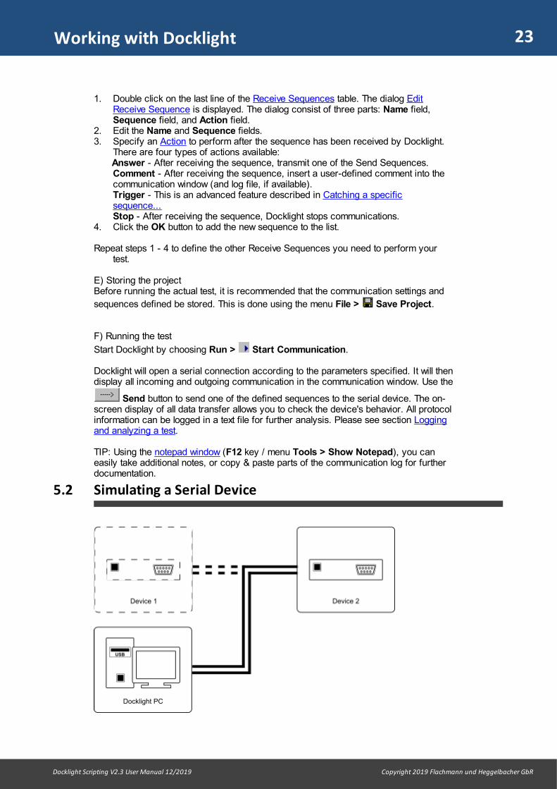
5.2 Simulating a Serial Device

24
Docklight Scripting V2.3 User Manual 12/2019 Copyright 2019 Flachmann und Heggelbacher GbR
Working with Docklight
Preconditions
· You need the specification of the behavior of the serial device you want to simulate,e.g. what kind of information is sent back after receiving a certain command.
· A second device is connected to a PC COM port, which will communicate with yoursimulator.
This second device and its behavior is the actual object of interest. An example could bea device that periodically checks the status of an UPS (Uninterruptible Power Supply)using a serial communication protocol. You could use Docklight to simulate basic UPSbehavior and certain UPS problem cases. This is very useful when testing the otherdevice, because it can be quite difficult to reproduce an alarm condition (like a badbattery) at the real UPS.
NOTE: The second device may also be a second software application. It is possible torun both Docklight and the software application on the same PC. Simply use a differentCOM port for each of the two applications and connect the two COM ports using aRS232 null modem cable. You can also use a virtual null modem for this purpose.
Performing the test
A) Creating a new project
Create a new Docklight project by selecting the menu File > New Project
B) Setting the Communication Options
1. Choose the menu Tools > Project Settings...2. Choose communication mode Send/Receive3. At Send/Receive on comm. channel, set the COM Port where your serial device
is connected.4. Set the baud rate and all other COM Port Settings required.5. Confirm the settings and close the dialog by clicking the OK button.
C) Defining the Send Sequences usedDefine all the responses of your simulator. Think of responses when the simulateddevice is in normal conditions, as well as responses when in fault condition. In the UPSexample mentioned above, a battery failure would be such a problem case that is hardto reproduce with the original equipment. To test how other equipment reacts to abattery failure, define the appropriate response sequence your UPS would send in thiscase. NOTE: See Testing a serial device... to learn how to define Send Sequences.
D) Defining the Receive Sequences usedIn most cases, your simulated device will not send unrequested data, but will be polledfrom the other device. The other device will use a set of predefined commandsequences to request different types of information. Define the command sequencesthat must be interpreted by your simulator here.
For every command sequence defined, specify Answer as an action. Choose one ofthe sequences defined in C). If you want to use two or more alternative responsesequences, make several copies of the same Receive Sequence, give them a differentname (e.g. "status cmd - answer ok", "status cmd - answer battery failure", "status cmd- answer mains failure") and assign different Send Sequences as an action. In theexample, you would have three elements in the Receive Sequences list that wouldrespond to the same command with three different answers. During the test you may

25
Docklight Scripting V2.3 User Manual 12/2019 Copyright 2019 Flachmann und Heggelbacher GbR
Working with Docklight
decide which answer should be sent by checking or unchecking the list elements usingthe Active column.
E) Storing the projectBefore running the actual test, it is recommended that the communication settings and
sequences defined be stored. This is done using the menu File > Save Project.
F) Running the test
Start Docklight by choosing Run > Start Communication.
Docklight will now respond to all commands received from the connected serial device. The on-screen data transfer display allows you to monitor the communications flow. Allprotocol information can be logged to a text file for further analysis. See sectionLogging and analyzing a test.
TIP: Using the notepad window (F12 key / menu Tools > Show Notepad), you caneasily take additional notes, or copy & paste parts of the communication log for furtherdocumentation.
5.3 Monitoring Serial Communications Between Two Devices
Preconditions
· A Docklight Monitoring Cable, Docklight Tap or Docklight Tap Pro/485 is required totap the RS232 TX signals of both serial devices and feed them into Docklight, whilenot interfering with the communications between the devices.
· For a Docklight Monitoring Cable setup, two COM ports must be available on your PCfor monitoring. Each port will receive the data from one of the serial devices beingmonitored.
· Device 1 and Device 2 must be ready to operate.
Performing the test
A) Creating a new project
Create a new Docklight project by selecting the menu File > New Project

26
Docklight Scripting V2.3 User Manual 12/2019 Copyright 2019 Flachmann und Heggelbacher GbR
Working with Docklight
B) Setting the Communication Options
1. Choose the menu Tools > Project Settings...2. Choose communication mode Monitoring
Alternative I - Using Docklight Monitoring Cable:
3. At Receive Channel 1, set the COM Port where the monitoring signal from serialdevice 1 is received. At Receive Channel 2, set the COM port for the seconddevice.
NOTE: In Docklight Monitoring Mode, all received data from one COM port is re-sent on the TX channel of the opposite COM port ("Data Forwarding"). This doesnot have any effect for Docklight Monitoring Cable setups, since the TX signal is notconnected. But it can be useful for special applications where you need to route theserial data traffic through Docklight using standard RS232 cabling. If you require apure passive monitoring behavior where no TX data appears, you can disable the"Data Forwarding" using the menu Tools > Expert Options...
Alternative II - Using Docklight Tap / Docklight Tap Pro / Docklight Tap 485:
3. At Receive Channel 1, open the dropdown list, scroll down to the -- USB Taps --section and choose the first Tap port, e.g. TAP0. At Receive Channel 2, thesecond tap port (e.g. TAP1) is selected automatically.
4. Set the baud rate and all other communication parameters for the protocol beingused
NOTE: Make sure your PC's serial interfaces port works properly at the baud rateand for the communication settings used by Device 1 and Device 2. If Device 1and 2 use a high speed data transfer protocol, the PC's serial interfaces and theDocklight software itself might be too slow to receive all data properly.
5. Confirm the settings and close the dialog by clicking the OK button.
C) Defining the Receive Sequences usedDefine Receive Sequences, which should be marked in the test protocol or trigger anaction within Docklight. Docklight checks for Receive Sequence on both monitoringchannels, i.e. it does not matter whether the sequences come from serial device 1 orserial device 2.
NOTE: Since a special monitoring cable is used for this test, all communication betweenserial device 1 and serial device 2 will remain unbiased and no additional delays will beintroduced by Docklight itself. This is particularly important when using Docklight fortracking down timing problems. This means, however, that there is no way to influencethe serial communication between the two devices. While communication modeMonitoring is selected, it is not possible to use Send Sequences.
D) Storing the projectBefore running the actual test, it is recommended to store the communication settings
and sequences defined. This is done using the menu File > Save Project.
E) Running the test
Start Docklight by choosing Run > Start Communication, then activate the serialdevices 1 and 2 and perform a test run. Docklight will display all communicationbetween serial device 1 and serial device 2. Docklight uses different colors and fonttypes to make it easy to distinguish between data transmitted by device 1 or device 2.

27
Docklight Scripting V2.3 User Manual 12/2019 Copyright 2019 Flachmann und Heggelbacher GbR
Working with Docklight
The colors and font types can be chosen in the Display tab of the Tools > Options... dialog.
TIP: The Snapshot Function allows you to locate a rare sequence or error conditionin a communication protocol with a large amount of data.
TIP: See the sections How to Increase the Processing Speed... and How to Obtain BestTiming Accuracy to learn how to adjust Docklight for applications with high amounts ofdata, or increased timing accuracy requirements.
5.4 Catching a Specific Sequence and Taking a Snapshot of theCommunication
When monitoring serial communications between two devices, you might want to test fora rare error and the interesting parts would be just the serial communication before andafter this event. You could look for this situation by logging the test and searching thelog files for the characteristic error sequence. This could mean storing and analyzingseveral MB of data when you are actually just looking for a few bytes though, if theyappeared at all. As an alternative, you can use the Snapshot feature as describedbelow.
Preconditions
· Docklight is ready to run a test as described in the previous use cases, e.g.monitoring serial communications between two devices.
Taking a snapshot
A) Defining a trigger for the snapshot1. Define the sequence that appears in your error situation as a Receive Sequence.2. Check the Trigger tab in the "action" part of the Receive Sequence dialog: The
trigger option must be enabled if this is the sequence that you want to track down.
NOTE: Do not forget to disable the trigger option for all other Receive Sequences thatshould be ignored in your test so that they do not trigger the snapshot.
B) Creating a snapshot
Click on the Snapshot button of the toolbar. Docklight will start communications, butwill not display anything in the communication window. If the trigger sequence isdetected, Docklight will display communication data before and after the trigger event.Further data is processed, until the trigger sequence is located roughly in the middle ofthe communication window. Docklight will then stop communication and position thecursor at the trigger sequence.
5.5 Logging and Analyzing a Test
Preconditions
· Docklight is ready to run a test as described in the previous use cases, e.g.Testing a serial device or a protocol implementation
Logging the test
28
Docklight Scripting V2.3 User Manual 12/2019 Copyright 2019 Flachmann und Heggelbacher GbR
Working with Docklight
Click on the Start Logging button on the main toolbar.
A dialog window will open for choosing log file settings.
For each representation (ASCII, HEX, ...), a separate log file may be created. Chooseat least one representation. Log files will have a ".txt", ".htm" or ".rtf" file extension,depending on your file format choice. Docklight also adds the representation type to thefile name to distinguish the different log files. E.g. if the user specifies "Test1" as thebase log file name, the plain text ASCII file will be named "Test1_asc.txt", whereas anRTF HEX log file will be named "Test1_hex.rtf".
Confirm your log file settings and start logging by clicking the OK button.
To stop logging and close the log file(s), click the Stop Logging button on the maintoolbar. Unless the log file(s) have been closed, it is not possible to view their entirecontents.
TIP: If you have additional requirements for your log file format, e.g starting a new fileevery hour, you can use a Docklight script and the StartLogging method for thispurpose. See also the LogFileNamesTimestamp.zip sample script (folderExtra\LogFileNamesTimestamp in your Script Samples directory).
5.6 Checking for Sequences With Random Characters (ReceiveSequence Wildcards)
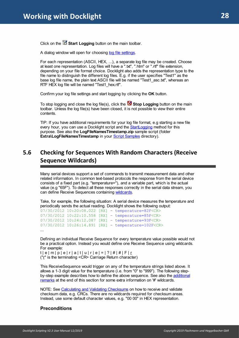
Many serial devices support a set of commands to transmit measurement data and otherrelated information. In common text-based protocols the response from the serial deviceconsists of a fixed part (e.g. "temperature="), and a variable part, which is the actualvalue (e.g "65F"). To detect all these responses correctly in the serial data stream, youcan define Receive Sequences containing wildcards.
Take, for example, the following situation: A serial device measures the temperature andperiodically sends the actual reading. Docklight shows the following output:07/30/2012 10:20:08.022 [RX] - temperature=82F<CR>07/30/2012 10:22:10.558 [RX] - temperature=85F<CR>07/30/2012 10:24:12.087 [RX] - temperature=93F<CR>07/30/2012 10:26:14.891 [RX] - temperature=102F<CR>...
Defining an individual Receive Sequence for every temperature value possible would notbe a practical option. Instead you would define one Receive Sequence using wildcards.For example:t | e | m | p | e | r | a | t | u | r | e | = | ? | # | # | F | r ("r" is the terminating <CR> Carriage Return character)
This ReceiveSequence would trigger on any of the temperature strings listed above. Itallows a 1-3 digit value for the temperature (i.e. from "0" to "999"). The following step-by-step example describes how to define the above sequence. See also the additionalremarks at the end of this section for some extra information on '#' wildcards.
NOTE: See Calculating and Validating Checksums on how to receive and validatechecksum data, e.g. CRCs. There are no wildcards required for checksum areas.Instead, use some default character values, e.g. "00 00" in HEX representation.
Preconditions

29
Docklight Scripting V2.3 User Manual 12/2019 Copyright 2019 Flachmann und Heggelbacher GbR
Working with Docklight
· Docklight is ready to run a test as described in the previous use cases, e.g. testing aserial device or a protocol implementation.
· The serial device (the temperature device in our example) is operating.
Using Receive Sequences with wildcards
A) Preparing the projectCreate a new Docklight project and set up all communication parameters.
B) Defining the Receive Sequences used1. Create a new Receive Sequence. Enter a Name for the sequence.2. Enter the fixed part of your expected answer in the Sequence section. For our
example you would enter the following sequence in ASCII mode:t | e | m | p | e | r | a | t | u | r | e | =
3. Open the popup / context menu using the right mouse button, and chooseWildcard '?' (matches one character) to insert the first wildcard at the cursorposition. Add two '#' wildcards using the popup menu Wildcard '#' (matches zeroor one character). The sequence now looks like this:t | e | m | p | e | r | a | t | u | r | e | = | ? | # | #
4. Enter the fixed tail of our temperature string, which is a letter 'F' and the terminating<CR> character. You can use the default control character shortcut Ctrl+Enter toenter the <CR> / ASCII code 13. The sequence is now:t | e | m | p | e | r | a | t | u | r | e | = | ? | # | # | F | r
5. Specify an Action to perform after a temperature reading has been detected.6. Click OK to add the new sequence to the Receive Sequence list.
NOTE: To distinguish the wildcards '?' and '#' from the regular question mark or numbersign characters (decimal code 63 / 35), the wildcards are shown on a differentbackground color within the sequence editor.
C) Running the test
Start Docklight by choosing Run > Start Communication.
Docklight will now detect any temperature reading and perform the specified action.
NOTE: The DL_OnReceive() event procedure allows further evaluation and processingof the actual measurement data received.
Additional notes on '#' wildcards
1. '#' wildcards at the end of a Receive Sequence have no effect. The ReceiveSequence "HelloWorld###" will behave like a Receive Sequence "HelloWorld".
2. A "match inside a match" is not returned: If a Receive Sequence"Hello#######World" is defined, and the incoming data is "Hello1Hello2World", theReceive Sequence detected is "Hello1Hello2World", not "Hello2World".
Receive Sequence comment macros
Macro keywords can be used in the Edit Receive Sequence > 3 - Action > Commenttext box, to create Docklight comment texts with dynamic data, e.g. the actual datareceived.
Macro Is Replaced By

30
Docklight Scripting V2.3 User Manual 12/2019 Copyright 2019 Flachmann und Heggelbacher GbR
Working with Docklight
%_S BELL signal. Produce a 'beep sound', depending on your Windowssound scheme.
%_L Line break
%_T Time stamp for the data received
%_C Docklight channel no. / data direction (1 or 2) for the data received
%_X The channel name or channel alias that corresponds to the datadirection %_C. E.g. "RX", "TX" or "COM5".
%_I Receive Sequence List Index, see the Dialog: Edit Receive Sequence
%_N Receive Sequence Name
%_A The actual data that triggered this Receive Sequence. Use ASCIIrepresentation
%_H Same as %_A, but in HEX representation
%_D Same as %_A, but in Decimal representation
%_B Same as %_A, but in Binary representation
%_A(1,4) Extended syntax: Insert only the first 4 characters of this Receive Sequence (start withCharacter No. 1, sequence length = 4).
%_H(3,-1)
Extended Syntax: Insert everything from the third character until the end of the sequence(length = -1). Use HEX representation.
Example:For a Receive Sequence as described above ( t | e | m | p | e | r | a | t | u | r | e | = | ?| # | # | F | r ), you could define the following comment text:
New Temp = %_L %_A(13, -3) °F
Docklight output could then look like this:
10/30/2012 10:20:08.022 [RX] - temperature=82F<CR> New Temp = 82 °F10/30/2012 10:22:10.558 [RX] - temperature=85F<CR> New Temp = 85 °F10/30/2012 10:24:12.087 [RX] - temperature=93F<CR> New Temp = 93 °F

31
Docklight Scripting V2.3 User Manual 12/2019 Copyright 2019 Flachmann und Heggelbacher GbR
Working with Docklight
5.7 Saving and Loading Your Project Data, Script and Options
In Docklight Scripting the program behavior is controlled by three different types of userdata:
· Project Data· Scripts· Program Options
Saving and Loading Project Data
The project data includes:· Send Sequences · Receive Sequences · Additional Project Settings: communication mode, COM ports used, COM port settings
(baud rate, parity, ...)· Notepad contents
The project is saved in a Docklight project file (.ptp file) using the menu File > SaveProject or File > Save Project As...
It is generally recommended to save your project before starting a test run.
NOTE: Saving your project only stores the project's sequences, settings and Notepaddata. If you want to save a log of the communication during a test run, see sectionlogging and analyzing a test.
Loading a project is done using the File > Open Project... menu.
Saving and Loading Scripts
Docklight script code for automated testing tasks is saved in a separate file (.pts file).Use the menu Scripting > Save Script or Scripting > Save Script As...
Saving and Loading Program Options
Docklight Options (text formatting, control-character behaviors, a.s.o) can be modified
by using the Docklight Options dialog (menu Tools > Options...).
When running your own script you may want to use a specific set of Options to ensurethe communication and log output are created in a certain way. This is possible byusing the SaveProgramOptions and LoadProgramOptions methods in your script.
Using Project and Script Pairs: _auto.pts
In most Docklight Scripting applications, a Docklight script (.pts file) requires anaccompanying project (.ptp file). You can use the following naming scheme to enableautomatic loading and script start:
myproject.ptpmyproject_auto.pts
If the two files are located in the same folder, Docklight Scripting will perform thefollowing additional operations:
32
Docklight Scripting V2.3 User Manual 12/2019 Copyright 2019 Flachmann und Heggelbacher GbR
Working with Docklight
· If myproject.ptp is opened (either double-click in Windows Explorer, or using menu
File > Open Project...), Docklight Scripting also opens myproject_auto.ptsalongside, if not already open.
· If myproject_auto.pts is opened, Docklight Scripting also opens myproject.ptpalongside, if not already open.
· If Start communication is executed, the communication port is opened and thescript is started.
NOTE: If myproject.ptp is opened in Docklight (non-scripting), a warning appears thatthis seems to be a project with script support and its use is limited in Docklight (non-scripting).
NOTE: The OpenProject and StartCommunication script methods are not affected bythe _auto.pts behavior.

Working with Docklight (Advanced)

34
Docklight Scripting V2.3 User Manual 12/2019 Copyright 2019 Flachmann und Heggelbacher GbR
Working with Docklight (Advanced)
6 Working with Docklight (Advanced)
6.1 Sending Commands With Parameters (Send SequenceWildcards)
When testing a serial device, the device will most likely support a number of commandsthat include a parameter.
Example: A digital camera supports a command to set the exposure time. For setting theexposure time to 25 milliseconds, you need to send the following sequence:e | x | p | | 0 | 2 | 5 | r ("r" is a terminating <CR> Carriage Return character)
To avoid defining a new Send Sequence for every exposure time you want to try, youcan use a Send Sequence with wildcards instead:e | x | p | | ? | ? | ? | r
The following step-by-step example describes how to define an exposure time commandwith a parameter and use a different exposure value each time the sequence is sent.
Preconditions
· Docklight is ready to run a test as described in testing a serial device or a protocolimplementation.
Performing the test using commands with parameters
A) Preparing the projectCreate a new Docklight project and set up all communication parameters.
B) Defining the commands used1. Create a new Send Sequence. Enter a Name for the sequence.2. Enter the fixed part of your command in the Sequence section. For our example
you would enter the following sequence in ASCII mode:e | x | p | |
3. Now open the context menu using the right mouse button, and choose Wildcard'?' (matches one character) F7 to insert one wildcard at the cursor position. Inour example we would have to repeat this until there are three '?' wildcards for ourthree-digit exposure time. The sequence now looks like this:e | x | p | | ? | ? | ?
4. Now add the terminating <CR> character, using the default control charactershortcut Ctrl+Enter. The example sequence now ise | x | p | | ? | ? | ? | r
5. Click OK to add the new sequence to the Send Sequence list.
Repeat steps 1 - 5 to define other commands needed to perform your test.
NOTE: To distinguish a '?' wildcard from a question mark ASCII character (decimalcode 63), the wildcard is shown on a different background color within the sequenceeditor.
C) Sending a command to the serial device
1. Use the Send button to open the serial communication port and send onecommand to the serial device.

35
Docklight Scripting V2.3 User Manual 12/2019 Copyright 2019 Flachmann und Heggelbacher GbR
Working with Docklight (Advanced)
2. The communication pauses and the Send Sequence Parameter dialog pops up,allowing you to enter the parameter value. In our example, an exposure time, e.g."025".
3. Confirm by pressing Enter. The sequence is now sent to the serial device.
It is possible to define commands with several parameters, using several wildcard areaswithin one sequence. The Send Sequence Parameter dialog will then appear severaltimes before sending out a sequence.
NOTE: If you are using Wildcard '?', you must provide exactly one character for each'?' when sending the sequence. For variable-length parameters use Wildcard'#' (matches zero or one character) F8.
NOTE: You cannot use a Send Sequence with wildcards as an automatic answer for aReceive Sequence (see Action).
NOTE: If your Send Sequence requires a checksum, you can define it as described inCalculating and Validating Checksums. The checksum is calculated after thewildcard/parameter area has been filled with the actual data, then the resultingsequence data is handed over to the send queue.
6.2 How to Increase the Processing Speed and Avoid "InputBuffer Overflow" Messages
When monitoring serial communications between two devices, Docklight cannot controlthe amount of incoming data. Since Docklight applies a number of formatting andconversion rules on the serial data, only a limited number of bytes per seconds can beprocessed. There are numerous factors that determine the processing speed, e.g. thePC and COM devices used, the Display Settings, and the Receive Sequence Actionsdefined. It is therefore not possible to specify any typical data rates.
The most time-consuming task for Docklight is the colors&font formatting applied bydefault (see the Docklight Display Options). If Docklight cannot keep up with formatting the incoming data, it will automatically switch to the simpler Plain Text Mode.
If this is still not fast enough to handle the incoming data, Docklight will add the followingmessage in the Communication Window output and log files.
DOCKLIGHT reports: Input buffer overflow on COM1
TIP: Search for this message using the Find Sequence in CommunicationWindow... (Ctrl + F) function.
If you are experiencing the above behavior, Docklight offers you several ways toincrease the data throughput.
1. Simplify the display output:
- Deactivate all unneeded Display Modes in the Options... dialog- Use Plain Text Mode right from the start (see the automatic switch behaviordescribed above).- If you are using ASCII mode, disable the Control Characters Description option
2. Log the communication data to a plain text file instead of using the communicationwindow(s):- Use the "plain text" Log File Format- Create only a log file for the Representation (ASCII / HEX / Decimal / Binary) youactually need
36
Docklight Scripting V2.3 User Manual 12/2019 Copyright 2019 Flachmann und Heggelbacher GbR
Working with Docklight (Advanced)
- Disable the communication windows while logging, using the High Speed Loggingoption
3. Use the Communication Filter from the Project Settings... dialog, and disablethe original serial data for one or both communication directions. This is especiallyuseful if you actually know what you are looking for and can define one or severalReceive Sequences for this pieces of data. These Receive Sequences can print acomment each time the sequence appears in the data stream so you still know whathas happened, even if the original serial data is not displayed by Docklight.
6.3 How to Obtain Best Timing Accuracy
Many RS232 monitoring applications – including Docklight – can only provide limitedaccuracy when it comes to time tagging the serial data. As a result, data from the twodifferent communication directions can be displayed in chronologically incorrect order,or several telegrams from one communication direction can appear as one chunk ofdata.
This behavior is not caused by poor programming, but is rather characteristic for aPC/Windows system, and the various hardware and software layers involved.Unspecified delays and timing inaccuracies can be introduced by: · The COM device’s chipset, e.g. the internal FIFO (First-In-First-Out) data buffer. · The USB bus transfer (for USB to Serial converters).· The serial device driver for Windows.· The task/process scheduling in a multitasking operating system like Windows. · The accuracy of the date/time provider.
Docklight comes with a very accurate date/time provider with milliseconds granularity,but it still needs to accept the restrictions from the hardware and software environmentaround it.
Here is what you can do to minimize additional delays and inaccuracies and achieve atypical time tagging accuracy of 5 milliseconds or better:
1. Get our Docklight Tap for lowest USB-related latency times. Or use on-boardRS232 ports, if still available on your PC.
2. Choose External / High Priority Process Mode in the Tools > Expert Options...dialog.
3. When monitoring high amounts of data, use the recommendations from theprevious section How to Increase the Processing Speed... to avoid input bufferoverflows and that the computer become irresponsive because of high CPU usage.
NOTE: The Expert Options... recommended above will change the overall systembalance and must be used with care. Best results can be achieved only when Docklightis Run as administrator. Please make sure you understood the remarks and warningin the documentation.
4. As an alternative to the above 1.-3.: Use our Docklight Tap Pro or Docklight Tap485 accessories which use their own Embedded time provider and eliminate PC-based inaccuracies altogether.
6.4 Calculating and Validating Checksums
Many communication protocols include additional checksum fields to ensure dataintegrity and detect transmission errors. A common algorithm is the CRC (Cyclic
37
Docklight Scripting V2.3 User Manual 12/2019 Copyright 2019 Flachmann und Heggelbacher GbR
Working with Docklight (Advanced)
Redundancy Code), which is used in different variations for different protocols. Thefollowing step-by-step example describes how to set up on-the-fly checksum calculationfor a Send Sequence, and how to enable automatic validation of a checksum areawithin a Receive Sequence.
TIP: For a working example to address a Modbus slave device, see the tutorial ModbusRTU With CRC checksum.
TIP: See also the DL.CalcChecksum method on how to calculate checksums usingscript code as an alternative.
Preconditions
You know the checksum specification for the protocol messages:· Which area of the sequence data is guarded by a checksum? · Where is the checksum located? (Usually at the end of the sequence.)· What checksum algorithm should be used? (Most likely one of the standard CRC
types, or a simple MOD256 sum.)
Using Send Sequences with automatic checksum calculation
A) Defining a Send Sequence that includes a checksum
1. Create a new Send Sequence. Enter a Name for the sequence.
2. Enter the Sequence part of your message in the Sequence section. For example,here we use a very simple HEX message as our sequence:01 | 02 | 03 | 04 | ??
Use the context menu via right mouse button or F7 to create the ?? wildcard.
NOTE: See also the Send Sequence Parameter section for more information onwildcards and parameters.
3. Now add one additional 00 value as a placeholder for the checksum.01 | 02 | 03 | 04 | ?? | 00
NOTE: In a Send Sequence, you can use any character code from 00-FF as aplaceholder at the positions where the calculated checksum should be insertedlater. This is different from the way it works in a Receive Sequence, where you use?? wildcards. See the Receive Sequence example below.
4. Go to the Additional Settings | Checksum tab and define the checksum. Forexample, here we chose to use MOD256 from the dropdown list.
NOTE: The text field for Checksum allows comments. Everything behind a #character is just a comment. You can add your own comments to describe whatthis checksum is about.
5. Click OK to add the new sequence to the Send Sequence list.
B) Performing the test
6. Use the Send button to send one of the predefined commands. Enter aparameter value, e.g. 05.
Before sending the data, Docklight calculates the actual MOD256 checksum. The resultgoes to the specified checksum position. For MOD256 this is the last character positionby default, which means that the 00 placeholder is overwritten with the checksum result.
38
Docklight Scripting V2.3 User Manual 12/2019 Copyright 2019 Flachmann und Heggelbacher GbR
Working with Docklight (Advanced)
If we use 05 as a parameter when sending the sequence, the data sent by Docklight willlook like this:
18.06.2015 11:07:23.251 [TX] - 01 02 03 04 05 0F
The placeholder has been replaced by the sum over the message bytes: 1 + 2 + 3 + 4 + 5 = 15 or Hex 0F.
Using Receive Sequences with automatic checksum validation
A) Defining a Receive Sequence with checksum
1. Create a new Receive Sequence. Enter a Name for the sequence.
2. Enter the Sequence data, including a wildcard area for both a random payloadbyte, plus a wildcard for the checksum. We use the same telegram as in the aboveSend Sequence example:01 | 02 | 03 | 04 | ?? | 00.
3. Go to the Action | Comment tab and enter the following text: Correct checksum
4. Go to the Checksum tab and pick MOD256 in the left dropdown list.
5. Keep the Detect Checksum OK option. It means that the Receive Sequence isonly triggered if the MOD256 checksum byte in the received data is correct.
5. Click OK to confirm the changes
B) Running the test
6. Start communications and send some data telegrams to your Docklight application /COM port.
The Communication Window output could look like this:
15.02.2016 17:43:28.072 [RX] - 01 02 03 04 05 0F Correctchecksum 15.02.2016 17:43:31.870 [RX] - 01 02 03 04 0F 19 Correctchecksum
15.02.2016 17:43:35.833 [RX] - 01 02 03 04 10 1A Correctchecksum
NOTE: This example showed how to define a Receive Sequence that is triggered bydata telegrams with correct checksum only. It is also possible to do the opposite:detecting a checksum error. Go to the Checksum tab and change the option DetectChecksum OK to Checksum Wrong.
6.5 Controlling and Monitoring RS232 Handshake Signals
The Docklight project settings for Flow Control support offer a Manual Mode that allowsyou to set or reset the RTS and DTR signals manually by clicking on the correspondingindicator. The following section describes how to use the Function Character '!' (F11

39
Docklight Scripting V2.3 User Manual 12/2019 Copyright 2019 Flachmann und Heggelbacher GbR
Working with Docklight (Advanced)
key) to change the RTS and DTR signals temporarily within a Send Sequence, or detectchanges for the CTS, DSR, DCD or RI lines using a Receive Sequence.
Preconditions
· Docklight is ready to run a test as described in testing a serial device or a protocolimplementation.
· Flow Control Support is set to "Manual" in the project settings.· The Docklight project already contains one or several Send Sequences, but there is
an additional requirement for changing RTS / DTR signals while sending.
Implementing RTS/DTR signal changes
For our example we assume that we are using a RS485 converter which requiresRS485 Transceiver Control, but uses the DTR signal instead of RTS for switchingbetween "transmit" and "receive" mode. We further assume there is already a "Test"Send Sequence which looks like this in ASCII mode: T | e | s | t
A) Modifying the existing Send Sequence
1. Open the Edit Send Sequence dialog. 2. Switch the Edit Mode to Decimal. Our "Test" example looks like this in decimal
mode: 084 | 101 | 115 | 116
3. Insert an RTS/DTR function character at the beginning: Press F11, or open thecontext menu using the right mouse button and choose Function character'!' (RTS and DTR signals) . The example sequence now reads: ! | 084 | 101 | 115 | 116
4. Add the new RTS/DTR state as a decimal parameter value (see below). In ourexample we need the DTR signal set to high. We choose "002" as the parametervalue, so the sequence is now: ! | 002 | 084 | 101 | 115 | 116
5. Add a RTS/DTR function character at the end of the sequence, and use "000" asparameter value to reset the DTR signal low. The sequence data is now: ! | 002 | 084 | 101 | 115 | 116 | ! | 000
6. Click OK to confirm the changes
NOTE: To distinguish a '!' RTS/DTR function character from a exclamation mark ASCIIcharacter (decimal code 33), the RTS/DTR function character is shown on a differentbackground color by the sequence editor.
NOTE: The character after a RTS/DTR function character is used to set the RTS / DTRsignals and is not sent to the serial device (see parameter values below).
B) Sending the data with additional DTR control
1. Send the test sequence using the Send button.
Docklight will now set the DTR signal to high, send the ASCII sequence "Test" and thenreset DTR.
NOTE: The RTS/DTR indicators will indicate any changes of the RTS or DTR state.However, in the above example the DTR is set and reset very quickly, so the DTRindicator will probably not give any visual feedback. If you want to actually "see" theDTR behavior, try introducing a small inter-character delay.
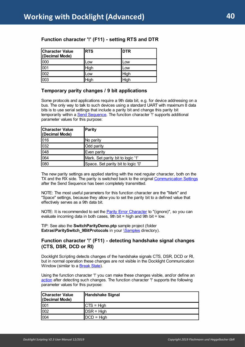
40
Docklight Scripting V2.3 User Manual 12/2019 Copyright 2019 Flachmann und Heggelbacher GbR
Working with Docklight (Advanced)
Function character '!' (F11) - setting RTS and DTR
Character Value(Decimal Mode)
RTS DTR
000 Low Low
001 High Low
002 Low High
003 High High
Temporary parity changes / 9 bit applications
Some protocols and applications require a 9th data bit, e.g. for device addressing on abus. The only way to talk to such devices using a standard UART with maximum 8 databits is to use serial settings that include a parity bit and change this parity bittemporarily within a Send Sequence. The function character '!' supports additionalparameter values for this purpose:
Character Value(Decimal Mode)
Parity
016 No parity
032 Odd parity
048 Even parity
064 Mark. Set parity bit to logic '1'
080 Space. Set parity bit to logic '0'
The new parity settings are applied starting with the next regular character, both on theTX and the RX side. The parity is switched back to the original Communication Settingsafter the Send Sequence has been completely transmitted.
NOTE: The most useful parameters for this function character are the "Mark" and"Space" settings, because they allow you to set the parity bit to a defined value thateffectively serves as a 9th data bit.
NOTE: It is recommended to set the Parity Error Character to "(ignore)", so you canevaluate incoming data in both cases, 9th bit = high and 9th bit = low.
TIP: See also the SwitchParityDemo.ptp sample project (folderExtras\ParitySwitch_9BitProtocols in your \Samples directory).
Function character '!' (F11) - detecting handshake signal changes(CTS, DSR, DCD or RI)
Docklight Scripting detects changes of the handshake signals CTS, DSR, DCD or RI,but in normal operation these changes are not visible in the Docklight CommunicationWindow (similar to a Break State).
Using the function character '!' you can make these changes visible, and/or define anaction after detecting such changes. The function character '!' supports the followingparameter values for this purpose:
Character Value(Decimal Mode)
Handshake Signal
001 CTS = High
002 DSR = High
004 DCD = High

41
Docklight Scripting V2.3 User Manual 12/2019 Copyright 2019 Flachmann und Heggelbacher GbR
Working with Docklight (Advanced)
008 RI (Ring Indicator) = High
NOTE: See also DL.GetHandshakeSignals() for the extended set of signal statessupported in Tap Pro / Tap RS485 applications.
Example Receive Sequence definitions in Decimal Edit Mode:
Receive Sequence(Decimal Mode)
Description
! | 001 triggers when CTS=high, all other signals low
! | 006 triggers when CTS=low, DSR=high, DCD=high, RI=low
! | ??? triggers on any change of the status lines
For the following example we assume that Docklight is ready to run a test as describedin testing a serial device or a protocol implementation and Flow Control Support is set to"Manual" in the project settings.
A) Create a new Receive Sequence for detecting handshake signal changes.
1. Open the Edit Receive Sequence dialog.2. Switch the Edit Mode to Decimal. 3. Insert a 'signals' function character at the beginning: Press F11, or open the
context menu using the right mouse button and choose Function character'!' (CTS/DSR/DCD/RI changes) .
4. Add the handshake state as a decimal parameter value (see above). In our examplewe want to detect when CTS is high, while all other signals are low. This means weneed to enter "001" as the parameter value, so the sequence is now: ! | 001
5. Specifiy a Comment for this sequence, e.g. "[CTS = high, DSR/DCD/RI = low]"6. Click OK to confirm the new sequence
B) Start the test and confirm that Docklight now detects when the CTS line changesfrom low to high.
NOTE: This example only works if CTS is the only handshake line with "high" level. For amore flexible approach, you can define the character after the '!' function character asa wildcard, and use the DL_OnReceive() event procedure to evaluate the state of thehandshake lines.
Function character '^' (F12) - bitwise comparisons
The Function Character ' ' can be added by pressing F12 in the Edit Receive Sequencedialog. After the ‘ ’ character, two additional character values specify which bits tocheck ( mask ) and which values to expect for these bits ( value ).
Receive Sequence(HEX Mode)
Description
| mask | value Is a match for the next character received, when the following istrue:((nextCharacterReceived XOR value) AND mask) = 0In other words - the ‘ ’ character picks only the bits marked inmask and compares them with the corresponding bits in value.See below for examples.
| 0F | 05 Is a match, when for the next character the following is true:

42
Docklight Scripting V2.3 User Manual 12/2019 Copyright 2019 Flachmann und Heggelbacher GbR
Working with Docklight (Advanced)
Bit 0 = 1Bit 1 = 0Bit 2 = 1Bit 3 = 0 Bit 4-7 = (don’t care)
! | | 04 | 04 This Receive Sequence triggers when the new handshakesignal state says DCD = High. All other handshake signals can have any state.
NOTE: This Receive Sequence will trigger for any change ofany handshake signal, in case DCD still remains High.
TIP: This extension is also demonstrated in the Docklight Scripting example projectDocklight_TapPro_Demo.ptp (see the folder Extras\TapPro in your \Samples directory)
6.6 Creating and Detecting Inter-Character Delays
Some applications, especially microcontroller applications without a dedicated serialdata buffer, require an extra delay between individual characters to avoid bufferoverflows and allow the microcontroller to execute other code.
In Docklight you can implement inter-character delays by inserting one or severalFunction Characters '&' (F9 key) in your Send Sequence data, followed by acharacter specifying the desired delay time from 0.01 seconds to 2.55 seconds.
You can also use the '&' delay character inside a Receive Sequence to specify aminimum silent time where no further characters should be received. This is useful fordetecting pauses in the data stream that indicate the beginning/end of a telegram,especially for protocols where there is no dedicated start or end character.
Preconditions
· Docklight is ready to run a test as described in testing a serial device or a protocolimplementation.
· The Docklight project already contains one or several Send Sequences, but anadditional delay at certain character positions is required.
Sending Data With Inter-Character Delays
As an example, we use a microcontroller application which understands a "get"command. In ASCII Mode, the Send Sequence would be: g | e | t | r ("r" is a terminating <CR> Carriage Return character)
The following steps describe how to add an additional delay of 20 milliseconds betweeneach character and avoid buffer overflows on the microcontroller side.
A) Modifying the existing Send Sequence
1. Open the Edit Send Sequence dialog. 2. Switch Edit Mode to Decimal. Our "get" example looks like this in decimal mode:
103 | 101 | 116 | 013 3. Insert a delay function character between the first and the second character: Press
F9, or open the context menu using the right mouse button, and chooseFunction character '&' (delay... . The example sequence now reads: 103 | & | 101 | 116 | 013

43
Docklight Scripting V2.3 User Manual 12/2019 Copyright 2019 Flachmann und Heggelbacher GbR
Working with Docklight (Advanced)
4. Add the delay time: In this example a decimal value of 002 (20 milliseconds) afterthe "&" function character is added. The sequence is now: 103 | & | 002 | 101 | 116 | 013
5. Insert a delay between all other inter-character positions: the delay character anddelay time can be copied using Ctrl+C, and pasted in the desired positions usingCtrl+V. Our example sequence finally reads: 103 | & | 002 | 101 | & | 002 | 116 | & | 002 | 013 Or back in ASCII Mode: g | & | o | e | & | o | t | & | o | r
6. Click OK to confirm the changes
NOTE: To distinguish a '&' delay character from a regular ampersand ASCII character(decimal code 38), the delay function character is shown on a different backgroundcolor by the sequence editor.
NOTE: The character after a delay function character is interpreted as the delay timeand is not sent to the serial device.
B) Sending the command to the microcontroller application
1. Send the modified Send Sequences using the Send button.
Docklight will send out the same data as before, but leave additional timing gaps asspecified by the delay characters. The communication display will show the samecommunication data as without the delays.
NOTE: Docklight's accuracy for delay timing is limited because it has no control overthe UART's internal TX FIFO buffer. The specified delay times for the '&' delay functioncharacter are minimum values. Measured delay values are significantly higher, becauseDocklight always waits a minimum time to ensure the UART TX FIFO buffer is empty.Also, the display format and the additional performance settings affects the timing. Ifyou have more specific requirements on Send Sequence timing and need to control theDocklight "wait time" as well as your UART FIFO settings, please contact our e-mailsupport.
TIP: If you require the same delay between each character of the transmitted data,have a look at the SendByteTiming.pts sample script (see the folderExtras\SendByteTiming in your Script Samples directory). This script willautomatically slice your Send Sequences into individual characters and send the data"byte-by-byte", using a predefined inter-character delay.
Pause detection using a Receive Sequence
Docklight already offers the Pause detection... display option to insert additional timestamps or line breaks after communication pauses.
If you require not only visual formatting, but need to define actions after a minimumpause, or simply make sure the Receive Sequence detection algorithm starts anew aftera pause, you can add the delay function character to your Receive Sequencedefinition.
In most applications the best place for the delay function character will be at thebeginning of the Receive Sequence, before the actual receive data characters. You canalso create a Receive Sequence that contains a delay/pause definition only, and noactual serial data. This can be very useful for implementing timing constraints, e.g.resetting the telegram detection after a pause occurred.
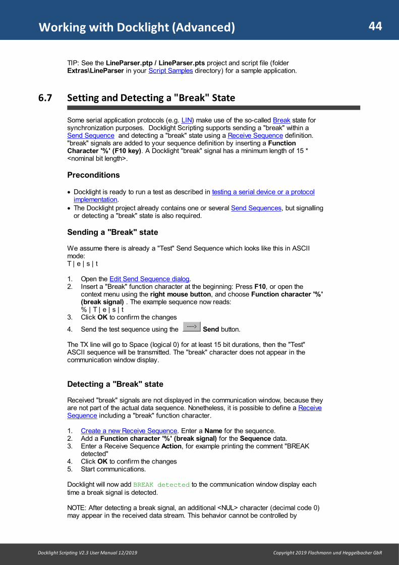
44
Docklight Scripting V2.3 User Manual 12/2019 Copyright 2019 Flachmann und Heggelbacher GbR
Working with Docklight (Advanced)
TIP: See the LineParser.ptp / LineParser.pts project and script file (folderExtras\LineParser in your Script Samples directory) for a sample application.
6.7 Setting and Detecting a "Break" State
Some serial application protocols (e.g. LIN) make use of the so-called Break state forsynchronization purposes. Docklight Scripting supports sending a "break" within aSend Sequence and detecting a "break" state using a Receive Sequence definition."break" signals are added to your sequence definition by inserting a FunctionCharacter '%' (F10 key). A Docklight "break" signal has a minimum length of 15 *<nominal bit length>.
Preconditions
· Docklight is ready to run a test as described in testing a serial device or a protocolimplementation.
· The Docklight project already contains one or several Send Sequences, but signallingor detecting a "break" state is also required.
Sending a "Break" state
We assume there is already a "Test" Send Sequence which looks like this in ASCIImode: T | e | s | t
1. Open the Edit Send Sequence dialog. 2. Insert a "Break" function character at the beginning: Press F10, or open the
context menu using the right mouse button, and choose Function character '%'(break signal) . The example sequence now reads: % | T | e | s | t
3. Click OK to confirm the changes
4. Send the test sequence using the Send button.
The TX line will go to Space (logical 0) for at least 15 bit durations, then the "Test"ASCII sequence will be transmitted. The "break" character does not appear in thecommunication window display.
Detecting a "Break" state
Received "break" signals are not displayed in the communication window, because theyare not part of the actual data sequence. Nonetheless, it is possible to define a ReceiveSequence including a "break" function character.
1. Create a new Receive Sequence. Enter a Name for the sequence.2. Add a Function character '%' (break signal) for the Sequence data.3. Enter a Receive Sequence Action, for example printing the comment "BREAK
detected"4. Click OK to confirm the changes5. Start communications.
Docklight will now add BREAK detected to the communication window display eachtime a break signal is detected.
NOTE: After detecting a break signal, an additional <NUL> character (decimal code 0)may appear in the received data stream. This behavior cannot be controlled by
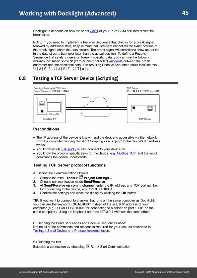
45
Docklight Scripting V2.3 User Manual 12/2019 Copyright 2019 Flachmann und Heggelbacher GbR
Working with Docklight (Advanced)
Docklight, it depends on how the serial UART of your PC's COM port interpretes thebreak state.
NOTE: If you need to implement a Receive Sequence that checks for a break signalfollowed by additional data, keep in mind that Docklight cannot tell the exact position ofthe break signal within the data stream. The break signal will sometimes show up earlierin the data stream, but never later than the actual position. To define a ReceiveSequence that safely triggers on break + specific data, you can use the followingworkaround: Insert some '#' (zero or one character) wildcards between the breakcharacter and the additional data. The resulting Receive Sequence could look like this: % | # | # | # | # | # | # | # | # | T | e | s | t
6.8 Testing a TCP Server Device (Scripting)
Preconditions
· The IP address of the device is known, and the device is accessible via the networkfrom the computer running Docklight Scripting - i.e. a 'ping' to the device's IP addressworks.
· You know which TCP port you can connect to your device on.· You know the protocol specification for the device, e.g. Modbus TCP, and the set of
commands the device understands.
Testing TCP Server protocol functions
A) Setting the Communication Options
1. Choose the menu Tools > Project Settings...2. Choose communication mode Send/Receive3. At Send/Receive on comm. channel, enter the IP address and TCP port number
for connecting to the device, e.g. 192.0.0.1:10001.4. Confirm the settings and close the dialog by clicking the OK button.
TIP: If you want to connect to a server that runs on the same computer as Docklight,you can use the keyword LOCALHOST instead of the actual IP address of yourcomputer (e.g. LOCALHOST:10001 for connecting to a server on port 10001 on thesame computer). Using the loopback address 127.0.0.1 will have the same effect.
B) Defining the Send Sequences and Receive Sequences used: Define all of the commands and responses required for your test, as described inTesting a Serial Device or a Protocol Implementation.
C) Running the test
Establish a connection by choosing Run > Start Communication.
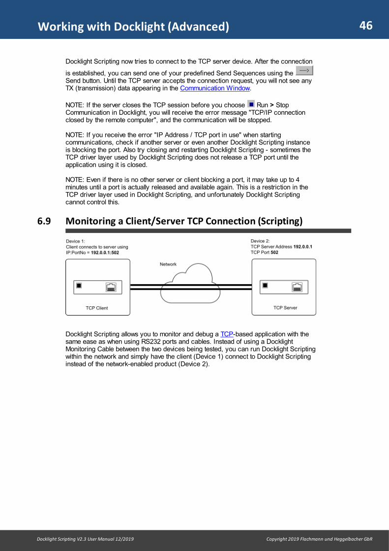
46
Docklight Scripting V2.3 User Manual 12/2019 Copyright 2019 Flachmann und Heggelbacher GbR
Working with Docklight (Advanced)
Docklight Scripting now tries to connect to the TCP server device. After the connection
is established, you can send one of your predefined Send Sequences using the Send button. Until the TCP server accepts the connection request, you will not see anyTX (transmission) data appearing in the Communication Window.
NOTE: If the server closes the TCP session before you choose Run > StopCommunication in Docklight, you will receive the error message "TCP/IP connectionclosed by the remote computer", and the communication will be stopped.
NOTE: If you receive the error "IP Address / TCP port in use" when startingcommunications, check if another server or even another Docklight Scripting instanceis blocking the port. Also try closing and restarting Docklight Scripting - sometimes theTCP driver layer used by Docklight Scripting does not release a TCP port until theapplication using it is closed.
NOTE: Even if there is no other server or client blocking a port, it may take up to 4minutes until a port is actually released and available again. This is a restriction in theTCP driver layer used in Docklight Scripting, and unfortunately Docklight Scriptingcannot control this.
6.9 Monitoring a Client/Server TCP Connection (Scripting)
Docklight Scripting allows you to monitor and debug a TCP-based application with thesame ease as when using RS232 ports and cables. Instead of using a DocklightMonitoring Cable between the two devices being tested, you can run Docklight Scriptingwithin the network and simply have the client (Device 1) connect to Docklight Scriptinginstead of the network-enabled product (Device 2).

47
Docklight Scripting V2.3 User Manual 12/2019 Copyright 2019 Flachmann und Heggelbacher GbR
Working with Docklight (Advanced)
Preconditions
· Device 1, Device 2 and the PC with Docklight are connected in a common network(LAN).
· All IP addresses and the TCP port number are known.· Device 1 is currently configured to connect to Device 2, and communications
between the two devices is working.
Route and debug TCP traffic
A) Route the traffic through Docklight ScriptingIn Device 1, change the communication parameters: Device 1 must connect to theDocklight PC (in our example IP 192.0.0.2).
B) Setup Docklight Scripting for operating as a bridge for the communication betweenDevice 1 and Device 2
1. Choose the menu Tools > Project Settings...2. Choose communication mode Monitoring (Receive only)3. For Receive Channel 1, type the keyword SERVER and the TCP port to listen on
(e.g. SERVER:502).4. For Receive Channel 2, type the IP address and TCP Port number for
connecting to Device 2 (e.g. 192.0.0.1:502).5. Confirm the settings and close the dialog by clicking the OK button.
C) Running the test
Start Docklight Scripting using Run > Start Communication. Let Device 1 connectand perform a test run. Docklight Scripting will act as a bridge between the devices andshow you all the TCP data transferred between the devices in the communicationwindow.
NOTE: Docklight Scripting does not allow multiple connections on a SERVER port. Onlyone connection at a time may be used. This is similar to the default operation of manySerial Device Servers.
48
Docklight Scripting V2.3 User Manual 12/2019 Copyright 2019 Flachmann und Heggelbacher GbR
Working with Docklight (Advanced)
TIP: An example that can be tried on any computer with a web browser and Internetaccess is the TCP_Monitoring_HTTP.ptp project which can be found in the \Networkfolder of the \ScriptSamples directory.
Examples and Tutorials

50
Docklight Scripting V2.3 User Manual 12/2019 Copyright 2019 Flachmann und Heggelbacher GbR
Examples and Tutorials
7 Examples and Tutorials
This chapter describes two sample projects that demonstrate some of Docklight's basicfunctions. The corresponding Docklight project files (.ptp files) can be found in the\Samples folder within the Docklight installation directory (e.g. C:\ProgramFiles\FuH\Docklight V2.3\Samples).
TIP: The \Samples folder can also be reached via the Docklight Welcome screen(menu Help > Welcome Screen and Examples... ).
NOTE: If you are logged on with a restricted user account, you will not have permissionto make any changes in the program files directory. In this case, saving a project file orany other data into the \Samples folder will produce an error.
NOTE: For additional sample projects and Application Notes, see also our onlineresources at https://docklight.de/examples/.
7.1 Testing a Modem - Sample Project: ModemDiagnostics.ptp
The Docklight project ModemDiagnostics.ptp can be used to perform a modem check.A set of modem diagnostic commands are defined in the Send Sequences list.
This is a simple example for Testing a serial device or a protocol implementation. Thesample project uses the communication settings listed below. This should work for moststandard modems.
Communication Mode Send/Receive
COM Port Settings 9600 Baud, No parity, 8 Data Bits, 1 Stop Bit
Getting started
· Use the Windows Device Manager to find out which COM Port is a modem device.This demo project may be used with any AT-compatible modem available on your PC,e.g. a built-in notebook modem, or a GSM or Bluetooth modem driver than can beaccessed through a virtual COM port.
TIP: For a simple test without specialized hardware, add your mobile phone asBluetooth Device on your Windows PC. Then find your phone in the WindowsDevices and Printers list. Right-click on it, choose Properties and go to theHardware tab. In the Device Functions list it should mention the modem relatedCOM Ports.
· Go to the Project Settings... dialog and make sure you have selected the sameCOM Port for Send/Receive on comm. channel.
· Press the Start Communication button in the toolbar.
· Try sending any of the predefined modem commands by pressing the Sendbutton
You should now receive a response from your modem, e.g. "OK" if your command wasaccepted, a model identification number, etc. The response will vary with the modemmodel.
After sending several sequences, the Docklight communication window could look likethis:
07.02.2013 18:17:54.083 [TX] - ATQ0V1E0<CR><LF>

51
Docklight Scripting V2.3 User Manual 12/2019 Copyright 2019 Flachmann und Heggelbacher GbR
Examples and Tutorials
07.02.2013 18:17:54.107 [RX] - ATQ0V1E0<CR><LF><CR><LF>OK<CR><LF>
07.02.2013 18:18:00.511 [TX] - ATI2<CR><LF>
07.02.2013 18:18:00.747 [RX] - <CR><LF>V 11.10<CR><LF>13-05-11<CR><LF>RM-721<CR><LF>(c) Nokia <CR><LF><CR><LF>OK<CR><LF>
07.02.2013 18:18:01.393 [TX] - ATI3<CR><LF>
07.02.2013 18:18:01.421 [RX] - <CR><LF>Nokia C2-01<CR><LF><CR><LF>OK<CR><LF>...
Further Information
The Send Sequences list includes the following standard AT modem commands:
Send Sequence Description / Modem Response
ATQ0V1E0 Initializes the query.
AT+GMM Model identification (ITU V.250 recommendation is notsupported by all modems).
AT+FCLASS=? Fax classes supported by the modem, if any.
AT#CLS=? Shows whether the modem supports the Rockwell voicecommand set.
ATI<n> Displays manufacturer's information for <n> = 1 through 7.This provides information such as the port speed, the resultof a checksum test, and the model information. Check themanufacturer's documentation for the expected results.
The \Samples folder also contains a log file ModemDiagnostics_Logfile_asc.txt. Itshows a test run where the above Send Sequences were sent to a real modem.
7.2 Reacting to a Receive Sequence - Sample Project:PingPong.ptp
The Docklight project PingPong.ptp is a simple example for how to define and useReceive Sequences.
Getting started
· Go to the Project Settings... dialog and choose a COM port.· Apply a simple loopback to this COM port: Connect Pin 2 (RX) with Pin 3 (TX). See
RS232 SUB D9 Pinout.
· Now press the Send button for either of the two Send Sequences.Communication is started and the Send Sequence is transmitted. It will of course beinstantly received on the COM port's RX line.

52
Docklight Scripting V2.3 User Manual 12/2019 Copyright 2019 Flachmann und Heggelbacher GbR
Examples and Tutorials
Docklight will detect the incoming data as being one of the defined Receive Sequences.It will then perform the action predefined for this event, which is sending out anothersequence. As a result, Docklight will send out alternating Send Sequences - "Ping" and"Pong".
· Use the Stop communication button to end the demo.
The Docklight communication display should look similar to this:
3/8/2009 16:25:44.201 [TX] - ----o Ping3/8/2009 16:25:44.216 [RX] - ----o Ping "Ping" received 3/8/2009 16:25:44.218 [TX] - o---- Pong3/8/2009 16:25:44.233 [RX] - o---- Pong "Pong" received 3/8/2009 16:25:44.236 [TX] - ----o Ping3/8/2009 16:25:44.251 [RX] - ----o Ping "Ping" received 3/8/2009 16:25:44.254 [TX] - o---- Pong3/8/2009 16:25:44.268 [RX] - o---- Pong "Pong" received 3/8/2009 16:25:44.271 [TX] - ----o Ping3/8/2009 16:25:44.286 [RX] - ----o Ping "Ping" received 3/8/2009 16:25:44.289 [TX] - o---- Pong3/8/2009 16:25:44.303 [RX] - o---- Pong "Pong" received 3/8/2009 16:25:44.307 [TX] - ----o Ping3/8/2009 16:25:44.322 [RX] - ----o Ping "Ping" received 3/8/2009 16:25:44.324 [TX] - o---- Pong...
See also the corresponding log files in the \Samples folder(PingPong_Logfile_asc.htm and PingPong_Logfile_hex.htm).
Further Information
This demo project can also be run in three alternative configurations:
1. Run two Docklight applications on the same PC using different COM ports. The twoCOM ports are connected using a simple null modem cable.
2. Instead of two RS232 COM ports and a null modem cable you can use a virtual nullmodem.
3. Use two PCs and run Docklight on each PC. Connect the two PCs using a simplenull modem cable.
TIP: For Docklight Scripting there is also a related example project that uses a UDPloopback connection, and does not require any serial data ports. See thePingPong_UDP_Loopback.ptp project in the \Network folder of the \ScriptSamplesdirectory.
7.3 Modbus RTU With CRC checksum - Sample Project:ModbusRtuCrc.ptp
The Docklight project file ModbusRtuCrc.ptp demonstrates how to automaticallycalculate the CRC value required to send a valid Modbus RTU frame.

53
Docklight Scripting V2.3 User Manual 12/2019 Copyright 2019 Flachmann und Heggelbacher GbR
Examples and Tutorials
The project file uses the communication settings listed below, according to the Modbusimplementation class "Basic".
Communication Mode Send/Receive
Send/Receive on comm. channel COM1
COM Port Settings 19200 Baud, Even parity, 8 Data Bits, 1 Stop Bit
Getting started
· Open the project file ModbusRtuCrc.ptp (menu Open Project ...). The file islocated in the \Samples folder.
· Connect the PC's COM port to your Modbus network. Open the ProjectSettings... dialog and make sure you have selected the correct COM Port forSend/Receive on comm. channel.
· Click the Send button in the Read Input Register Slave=?.. line of the SendSequence list
· Enter a slave number in the Send Sequence Parameter dialog, e.g. "01" foraddressing slave no. 1.
After sending "Read Input Register" commands to slaves 1 - 4, the communicationwindow could look like this:
23.09.2019 07:04:56.170 [TX] - 01 04 00 03 00 01 C1 CA 23.09.2019 07:04:56.282 [RX] - 01 04 02 FF FF B8 80 Detected Modbus Frame = 01 04 02 FF FF B8 80SlaveID=01FunctionCode=04Addr/Data=02 FF FFCRC=B8 80 Input Register Answer: Slave=001 ValueHex=FFFF
23.09.2019 07:05:21.761 [TX] - 02 04 00 03 00 01 C1 F9 23.09.2019 07:05:21.873 [RX] - 02 04 02 7F 58 DC FA Detected Modbus Frame = 02 04 02 7F 58 DC FASlaveID=02FunctionCode=04Addr/Data=02 7F 58CRC=DC FA Input Register Answer: Slave=002 ValueHex=7F58
23.09.2019 07:05:35.713 [TX] - 03 04 00 03 00 01 C0 28 23.09.2019 07:05:35.824 [RX] - 03 04 02 01 0A 41 67 Detected Modbus Frame = 03 04 02 01 0A 41 67SlaveID=03FunctionCode=04Addr/Data=02 01 0ACRC=41 67 Input Register Answer: Slave=003 ValueHex=010A
23.09.2019 07:05:51.677 [TX] - 04 04 00 03 00 01 C1 9F 23.09.2019 07:05:51.789 [RX] - 04 04 02 40 00 44 F0 Detected Modbus Frame = 04 04 02 40 00 44 F0SlaveID=04FunctionCode=04
54
Docklight Scripting V2.3 User Manual 12/2019 Copyright 2019 Flachmann und Heggelbacher GbR
Examples and Tutorials
Addr/Data=02 40 00CRC=44 F0 Input Register Answer: Slave=004 ValueHex=4000
The [RX] channel shows the responses from the Modbus slaves: slave 1 responded value "-1", slave 2 responded "32600", slave 3 responded "266" and slave 4 responded "16384".
NOTE: If you are using the Docklight Modbus example on a RS485 bus and do not seea device answer, check if your RS485 hardware interface automatically switchesbetween transmit and receive mode, or you need to use the RS485 Transceiver Controloption.
Further Information
· The CRC calculation is made according to the specifications for Modbus serial linetransmission (RTU mode). Docklight's checksum function supports a "CRC-MODBUS"model for this purpose. See Calculating and Validating Checksums for more generalinformation on implementing checksum calculations.
· If you do not have any Modbus slave devices available, you can use a softwaresimulator. See the www.plcsimulator.org/ as originally mentioned on www.modbus.org, "Modbus Technical Resources", "Modbus Serial RTU Simulator".This simulator was used to produce the sample data shown above.

Examples and Tutorials (Scripting)
56
Docklight Scripting V2.3 User Manual 12/2019 Copyright 2019 Flachmann und Heggelbacher GbR
Examples and Tutorials (Scripting)
8 Examples and Tutorials (Scripting)
This chapter describes sample scripts that demonstrate some of the possibilities whenusing Docklight Scripting. The corresponding Docklight script files (.pts files) and otherrelated files can be found in the folder \ScriptSamples within the Docklight Scriptinginstallation directory (e.g. C:\Program Files\FuH\Docklight ScriptingV2.3\ScriptSamples).
TIP: The \ScriptSamples folder can also be reached via the Docklight ScriptingWelcome screen (menu Help > Welcome Screen and Examples... ).
NOTE: If you are working with a user account which has restricted system access, youmight not have permission to save into the program files directory. In this case, saving aproject file or any other data into the \ScriptSamples folder will produce an error.
NOTE: For additional sample scripts, projects and Application Notes, see our onlineresources at https://docklight.de/examples/.
8.1 Automated Modem Testing - Sample Script:ModemScript.pts
The Docklight script ModemScript.pts and the accompanying project fileModemATCommands.ptp demonstrate how to use a Docklight script for an automatedtest or configuration task with user interaction.
The project file uses the communication settings listed below. This should work for moststandard modems.
Communication Mode Send/Receive
Send/Receive on comm. channel COM3
COM Port Settings 9600 Baud, No parity, 8 Data Bits, 1 Stop Bit
Getting started
· Connect the modem to an available COM port, e.g. COM1, and switch it on. The demomay also run on a notebook with a built-in modem. In many cases you will find yournotebook's built-in modem on COM3, so you can try and run the sample script withoutmodifying the project settings.
· Go to the Project Settings... dialog and make sure you have selected the sameCOM Port for Send/Receive on comm. channel.
· Press the Run Script button in the toolbar.· Type in the AT command range to be tested, or simply accept the default value by
pressing Enter.
The script now establishes a connection with the modem and runs through the ATcommand set. After successfully completing the test run, the Docklight communicationwindow could look like this:
Waiting for modem ...
3/8/2009 16:23:08.870 [TX] - ATQ0V1E0<CR><LF>
3/8/2009 16:23:08.873 [RX] - ATQ0V1E0<CR><CR><LF>OK<CR><LF>

57
Docklight Scripting V2.3 User Manual 12/2019 Copyright 2019 Flachmann und Heggelbacher GbR
Examples and Tutorials (Scripting)
Checking AT command set...
3/8/2009 16:23:08.888 [TX] - ATI0<CR><LF>
3/8/2009 16:23:08.891 [RX] - <CR><LF>Agere SoftModem Version 2.1.46<CR><LF><CR><LF>OK<CR><LF>
3/8/2009 16:23:09.091 [TX] - ATI1<CR><LF>
3/8/2009 16:23:09.101 [RX] - <CR><LF>OK<CR><LF>
3/8/2009 16:23:09.293 [TX] - ATI2<CR><LF>
3/8/2009 16:23:09.294 [RX] - <CR><LF>OK<CR><LF>
3/8/2009 16:23:09.496 [TX] - ATI3<CR><LF>
3/8/2009 16:23:09.498 [RX] - <CR><LF>Agere SoftModem Version 2.1.46<CR><LF><CR><LF>OK<CR><LF>
3/8/2009 16:23:09.700 [TX] - ATI4<CR><LF>
3/8/2009 16:23:09.702 [RX] - <CR><LF>Built on 07/22/2004 14:50:10<CR><LF><CR><LF>OK<CR><LF>
3/8/2009 16:23:09.901 [TX] - ATI5<CR><LF>
3/8/2009 16:23:09.912 [RX] - <CR><LF>2.1.46, AMR Intel MB, AC97 ID:SIL REV:0x27, 06<CR><LF><CR><LF>OK<CR><LF>
3/8/2009 16:23:10.104 [TX] - ATI6<CR><LF>
3/8/2009 16:23:10.110 [RX] - <CR><LF>OK<CR><LF>
3/8/2009 16:23:10.308 [TX] - ATI7<CR><LF>
3/8/2009 16:23:10.315 [RX] - <CR><LF>AMR Intel MB<CR><LF><CR><LF>OK<CR><LF>
3/8/2009 16:23:10.510 [TX] - ATI8<CR><LF>
3/8/2009 16:23:10.513 [RX] - <CR><LF>AC97 ID:SIL REV:0x27<CR><LF><CR><LF>

58
Docklight Scripting V2.3 User Manual 12/2019 Copyright 2019 Flachmann und Heggelbacher GbR
Examples and Tutorials (Scripting)
OK<CR><LF>
3/8/2009 16:23:10.713 [TX] - ATI9<CR><LF>
3/8/2009 16:23:10.723 [RX] - <CR><LF>Germany<CR><LF><CR><LF>OK<CR><LF>
3/8/2009 16:23:10.916 [TX] - ATI10<CR><LF>
3/8/2009 16:23:10.921 [RX] - <CR><LF>OK<CR><LF>
3/8/2009 16:23:11.119 [TX] - ATI11<CR><LF>
3/8/2009 16:23:11.120 [RX] - Description Status<CR><LF>--------------- ------------<CR><LF>Last Connection Unknown<CR><LF>Initial Transmit Carrier Rate 0<CR><LF>Initial Receive Carrier Rate 0<CR><LF>Final Transmit Carrier Rate 9600<CR><LF>Final Receive Carrier Rate 9600<CR><LF>Protocol Negotiation Result NONE<CR><LF>Data Compression Result NONE<CR><LF>Estimated Signal/Noise Ratio (dB) 00<CR><LF>Receive Signal Power Level (-dBm) 00<CR><LF>Transmit Signal Power Level (-dBm) 10<CR><LF>Round Trip Delay (msec) 1000<CR><LF>Near Echo Level (-dBm) 00<CR><LF>Far Echo Level (-dBm) 00<CR><LF>Transmit Frame Count 0<CR><LF>Transmit Frame Error Count 0<CR><LF>Receive Frame Count 0<CR><LF>Receive Frame Error Count 0<CR><LF>Retrain by Local Modem 0<CR><LF>Retrain by Remote Modem 0<CR><LF>Rate Renegotiation by Local Modem 0<CR><LF>Rate Renegotiation by Remote Modem 0<CR><LF>Call Termination Cause 0<CR><LF>Robbed-Bit Signaling 0<CR><LF>Digital Loss (dB) 00<CR><LF>Remote Server ID NA<CR><LF><CR><LF>OK<CR><LF>
3/8/2009 16:23:11.441 [TX] - ATI12<CR><LF>
3/8/2009 16:23:11.443 [RX] - <CR><LF>OK<CR><LF>
3/8/2009 16:23:11.643 [TX] - ATI13<CR><LF>
3/8/2009 16:23:11.654 [RX] - <CR><LF>ERROR<CR><LF>
3/8/2009 16:23:11.846 [TX] - ATI14<CR><LF>

59
Docklight Scripting V2.3 User Manual 12/2019 Copyright 2019 Flachmann und Heggelbacher GbR
Examples and Tutorials (Scripting)
3/8/2009 16:23:11.852 [RX] - <CR><LF>ERROR<CR><LF> Results: Found 13 valid AT commands. 2 AT command(s) did not work.
8.2 Startup From Command Line - Sample Script:LogStartupScript.pts
The Docklight script LogStartupScript.pts, the related project fileLogStartupSettings.ptp, and the batch file LogStartup.bat demonstrate how to startDocklight from the command line, create a log file according to predefined settings andstart communications automatically.
The project file uses the communication settings listed below.
Communication Mode Monitoring (receive only)
Receive channel 1 COM1
Receive channel 2 COM3
COM Port Settings 9600 Baud, No parity, 8 Data Bits, 1 Stop Bit
Getting started
· Start the batch file LogStartup.bat from a command line or go to the \ScriptSamplesdirectory and run LogStartup.bat by double-clicking the file.
Docklight Scripting is started, an ASCII log file C:\DocklightScripting_Logfile_asc.txtis created and communication is started immediately.
Use Shift+F6 to stop the script's execution and close the communication ports and logfile.
NOTE: This sample requires a software license for the Docklight standard version, sinceit makes use of the Docklight Logging function. A Docklight Scripting license is notrequired when running the sample.
Further Information
The batch file, LogStartup.bat, contains the following line:
..\Docklight_Scripting.exe -r LogStartupScript.pts
This will start Docklight Scripting, open the script file LogStartupScript.pts and run itimmediately (-r option). The script LogStartupScript.pts contains the followingcommands:
' LogStartupScript.pts' Start up logging and communicationDL.OpenProject "LogStartupSettings"' Create (or append to) a ASCII log fileDL.StartLogging "C:\DocklightScripting_Logfile", True, "A"DL.StartCommunication' Keep communication & logging alive until user stopsDo
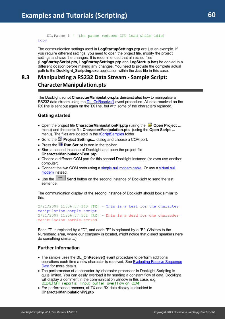
60
Docklight Scripting V2.3 User Manual 12/2019 Copyright 2019 Flachmann und Heggelbacher GbR
Examples and Tutorials (Scripting)
DL.Pause 1 ' (the pause reduces CPU load while idle)Loop
The communication settings used in LogStartupSettings.ptp are just an example. Ifyou require different settings, you need to open the project file, modify the projectsettings and save the changes. It is recommended that all related files(LogStartupScript.pts, LogStartupSettings.ptp and LogStartup.bat) be copied to adifferent location before making any changes. You need to provide the complete actualpath to the Docklight_Scripting.exe application within the .bat file in this case.
8.3 Manipulating a RS232 Data Stream - Sample Script:CharacterManipulation.pts
The Docklight script CharacterManipulation.pts demonstrates how to manipulate aRS232 data stream using the DL_OnReceive() event procedure. All data received on theRX line is sent out again on the TX line, but with some of the characters replaced.
Getting started
· Open the project file CharacterManipulationPrj.ptp (using the Open Project ...menu) and the script file CharacterManipulation.pts (using the Open Script ...menu). The files are located in the \ScriptSamples folder.
· Go to the Project Settings... dialog and choose a COM port.
· Press the Run Script button in the toolbar.· Start a second instance of Docklight and open the project file
CharacterManipulationTest.ptp.· Choose a different COM port for this second Docklight instance (or even use another
computer).· Connect the two COM ports using a simple null modem cable. Or use a virtual null
modem instead.
· Use the Send button on the second instance of Docklight to send the testsentence.
The communication display of the second instance of Docklight should look similar tothis:
2/21/2009 11:56:57.343 [TX] - This is a test for the charactermanipulation sample script2/21/2009 11:56:57.502 [RX] - Dhis is a desd for dhe characdermanibuladion samble scribd
Each "T" is replaced by a "D", and each "P" is replaced by a "B". (Visitors to theNuremberg area, where our company is located, might notice that dialect speakers heredo something similar...)
Further Information
· The sample uses the DL_OnReceive() event procedure to perform additionaloperations each time a new character is received. See Evaluating Receive SequenceData for more details.
· The performance of a character-by-character processor in Docklight Scripting isquite limited. You can easily overload it by sending a constant flow of data. Docklightwill display a comment in the communication window in this case, e.g. DOCKLI GHT r epor t s: I nput buf f er over f l ow on COM1
· For performance reasons, all TX and RX data display is disabled inCharacterManipulationPrj.ptp
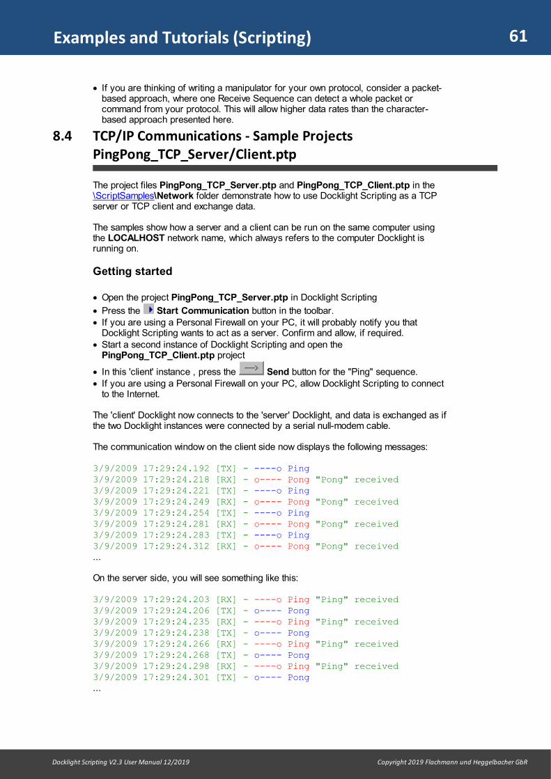
61
Docklight Scripting V2.3 User Manual 12/2019 Copyright 2019 Flachmann und Heggelbacher GbR
Examples and Tutorials (Scripting)
· If you are thinking of writing a manipulator for your own protocol, consider a packet-based approach, where one Receive Sequence can detect a whole packet orcommand from your protocol. This will allow higher data rates than the character-based approach presented here.
8.4 TCP/IP Communications - Sample ProjectsPingPong_TCP_Server/Client.ptp
The project files PingPong_TCP_Server.ptp and PingPong_TCP_Client.ptp in the\ScriptSamples\Network folder demonstrate how to use Docklight Scripting as a TCPserver or TCP client and exchange data.
The samples show how a server and a client can be run on the same computer usingthe LOCALHOST network name, which always refers to the computer Docklight isrunning on.
Getting started
· Open the project PingPong_TCP_Server.ptp in Docklight Scripting
· Press the Start Communication button in the toolbar. · If you are using a Personal Firewall on your PC, it will probably notify you that
Docklight Scripting wants to act as a server. Confirm and allow, if required. · Start a second instance of Docklight Scripting and open the
PingPong_TCP_Client.ptp project
· In this 'client' instance , press the Send button for the "Ping" sequence.· If you are using a Personal Firewall on your PC, allow Docklight Scripting to connect
to the Internet.
The 'client' Docklight now connects to the 'server' Docklight, and data is exchanged as ifthe two Docklight instances were connected by a serial null-modem cable.
The communication window on the client side now displays the following messages:
3/9/2009 17:29:24.192 [TX] - ----o Ping3/9/2009 17:29:24.218 [RX] - o---- Pong "Pong" received 3/9/2009 17:29:24.221 [TX] - ----o Ping3/9/2009 17:29:24.249 [RX] - o---- Pong "Pong" received 3/9/2009 17:29:24.254 [TX] - ----o Ping3/9/2009 17:29:24.281 [RX] - o---- Pong "Pong" received 3/9/2009 17:29:24.283 [TX] - ----o Ping3/9/2009 17:29:24.312 [RX] - o---- Pong "Pong" received ...
On the server side, you will see something like this:
3/9/2009 17:29:24.203 [RX] - ----o Ping "Ping" received 3/9/2009 17:29:24.206 [TX] - o---- Pong3/9/2009 17:29:24.235 [RX] - ----o Ping "Ping" received 3/9/2009 17:29:24.238 [TX] - o---- Pong3/9/2009 17:29:24.266 [RX] - ----o Ping "Ping" received 3/9/2009 17:29:24.268 [TX] - o---- Pong3/9/2009 17:29:24.298 [RX] - ----o Ping "Ping" received 3/9/2009 17:29:24.301 [TX] - o---- Pong...

Reference

63
Docklight Scripting V2.3 User Manual 12/2019 Copyright 2019 Flachmann und Heggelbacher GbR
Reference
9 Reference
9.1 Menu and Toolbar (Scripting)
NOTE: Hotkeys are available for common menu and toolbar functions.
File Menu
New ProjectClose the current Docklight project and create a new one.
Open Project ...Close the current Docklight project and open another project.
Import Sequence List ...Import all Send Sequences and Receive Sequences from a second Docklight project.
Save Project / Save Project As ...Save the current Docklight project.
Print Project ...Print the project data, i.e. the list of defined Send Sequences and Receive Sequences.The sequences are printed in the same representation (ASCII, HEX, Decimal or Binary)that is used in the Docklight main window. The representation may be chosen using theOptions dialog window.
Print Communication ...Print the contents of the communication window. The communication data is printed inthe same representation that is currently visible in the communication window.
ExitQuit Docklight.
Edit Menu
Edit Send Sequence List ...Edit the Send Sequences list, i.e. add new sequences or delete existing ones.
Edit Receive Sequence List ...Edit the Receive Sequences list, i.e. add new sequences or delete existing ones.
Swap Send and Receive Sequence ListsConvert all Send Sequences into Receive Sequences and vice versa.
Find Sequence in Communication Window...Find a specific sequence within the data displayed in the communication window. Seethe Find Sequence function.
Clear Communication WindowDelete the contents of the communications window. This applies to all fourrepresentations (ASCII, HEX, Decimal, Binary) of the communication window.
Run Menu
Start communicationOpen the communication ports and enable serial data transfer.

64
Docklight Scripting V2.3 User Manual 12/2019 Copyright 2019 Flachmann und Heggelbacher GbR
Reference
Stop communicationStop serial data transfer and close the communication ports.
Tools Menu
Start Communication Logging ...Create new log file(s) and start logging the incoming/outgoing serial data. See loggingand analyzing a test.
Stop Communication LoggingStop logging and close the currently open log file(s).
Start Snapshot ModeWait for a trigger sequence and take a snapshot. See Catching a specific sequence...
Stop Snapshot ModeAbort a snapshot and reenable the communication window display.
Keyboard Console OnEnable the keyboard console to send keyboard input directly.
Keyboard Console OffDisable the keyboard console.
Minimize/Restore Documentation and ScriptMinimize the Documentation and Script area, or bring it back to regular size.
Minimize/Restore Sequence ListsMinimize the Send/Receive Sequence lists, or bring them back to regular size.
Project Settings...Select the current project settings (COM ports, baud rate, ...).
Options...Select general program options (e.g. display mode, date / time stamp).
Expert Options...Select expert program options intended for advanced users and specific applications(e.g. high monitoring accuracy).
Scripting Menu
Run / Continue ScriptExecute the code in the script editor.
Stop ScriptStop a running script.
Break ScriptInterrupts a running script.
New ScriptClose the current Docklight script and create a new one.
Open Script ...Close the current Docklight script and open another script.

65
Docklight Scripting V2.3 User Manual 12/2019 Copyright 2019 Flachmann und Heggelbacher GbR
Reference
Save Script / Save Script As ...Save the current Docklight script.
Customize / External Editor...Use an external editor instead of Docklight's built-in editor.
9.2 Dialog: Edit Send Sequence
This dialog is used to define new Send Sequences and edit existing ones (See alsoEditing and Managing Sequences).
IndexThe index of the sequence displayed below. The first sequence has index 0 (zero).
1 - NameUnique name for this sequence (e.g. "Set modem speaker volume"). This name is forreferencing the sequence. It is not the data that will be sent out through the serial port.See "2 - Sequence" below.
2 - SequenceThe character sequence that will be transmitted through the serial port.
TIP: For transmitting larger blocks of data that exceed the maximum sequence size, usethe DL.UploadFile script command.
TIP: Special Function Characters are available for creating inter-character delays, sethandshake signals and parity bits, or setting a break state. 3 - Additional Settings· Repeat - Check the "Send periodically..." option to define a sequence that is sent
periodically. A time interval between 0.01 seconds and 9999 seconds can bespecified.
NOTE: The Windows reference time used for this purpose has only limited precision.Time intervals < 0.03 seconds will usually not be accurate.
· Checksum - Perform automatic calculation of any type of checksum, including anytype of CRC standard such as Modbus, CCITT, CRC32.
TIP: See Calculating and Validating Checksums for a general overview, and ChecksumSpecification for the text format used to define a checksum.
WildcardsWildcards can be used to introduce parameters into a Send Sequence that you wish toinsert manually each time the sequence is sent. See section Sending commands withparameters for details and examples.
Control Character ShortcutsUsing keyboard shortcuts is a great help when editing a sequence that contains bothprinting characters (letters A-z, digits 0-9, ...) and non-printing control characters(ASCII code 0 to 31). Predefined shortcuts are:Ctrl+Enter for carriage return / <CR> / decimal code 13Ctrl+Shift+Enter for line feed / <LF> / decimal code 10
Use Options... --> Control Character Shortcuts to define other shortcuts you finduseful.
Sequence Documentation
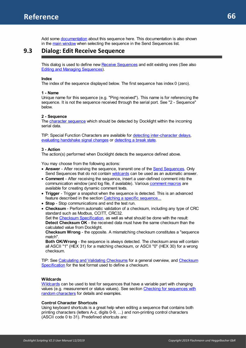
66
Docklight Scripting V2.3 User Manual 12/2019 Copyright 2019 Flachmann und Heggelbacher GbR
Reference
Add some documentation about this sequence here. This documentation is also shownin the main window when selecting the sequence in the Send Sequences list.
9.3 Dialog: Edit Receive Sequence
This dialog is used to define new Receive Sequences and edit existing ones (See alsoEditing and Managing Sequences).
IndexThe index of the sequence displayed below. The first sequence has index 0 (zero).
1 - NameUnique name for this sequence (e.g. "Ping received"). This name is for referencing thesequence. It is not the sequence received through the serial port. See "2 - Sequence"below.
2 - SequenceThe character sequence which should be detected by Docklight within the incomingserial data.
TIP: Special Function Characters are available for detecting inter-character delays,evaluating handshake signal changes or detecting a break state.
3 - ActionThe action(s) performed when Docklight detects the sequence defined above.
You may choose from the following actions:· Answer - After receiving the sequence, transmit one of the Send Sequences. Only
Send Sequences that do not contain wildcards can be used as an automatic answer.· Comment - After receiving the sequence, insert a user-defined comment into the
communication window (and log file, if available). Various comment macros areavailable for creating dynamic comment texts.
· Trigger - Trigger a snapshot when the sequence is detected. This is an advancedfeature described in the section Catching a specific sequence...
· Stop - Stop communications and end the test run.· Checksum - Perform automatic validation of a checksum, including any type of CRC
standard such as Modbus, CCITT, CRC32.Set the Checksum Specification, as well as what should be done with the result: Detect Checksum OK - the received data must have the same checksum than thecalculated value from Docklight.Checksum Wrong - the opposite. A mismatching checksum constitutes a "sequencematch". Both OK/Wrong - the sequence is always detected. The checksum area will containall ASCII "1" (HEX 31) for a matching checksum, or ASCII "0" (HEX 30) for a wrongchecksum.
TIP: See Calculating and Validating Checksums for a general overview, and ChecksumSpecification for the text format used to define a checksum.
WildcardsWildcards can be used to test for sequences that have a variable part with changingvalues (e.g. measurement or status values). See section Checking for sequences withrandom characters for details and examples.
Control Character ShortcutsUsing keyboard shortcuts is a great help when editing a sequence that contains bothprinting characters (letters A-z, digits 0-9, ...) and non-printing control characters(ASCII code 0 to 31). Predefined shortcuts are:

67
Docklight Scripting V2.3 User Manual 12/2019 Copyright 2019 Flachmann und Heggelbacher GbR
Reference
Ctrl+Enter for carriage return / <CR> / decimal code 13Ctrl+Shift+Enter for line feed / <LF> / decimal code 10
Use Options... --> Control Character Shortcuts to define other shortcuts you finduseful.
Sequence DocumentationAdd some documentation about this sequence here. This documentation is also shownin the main window when selecting the sequence in the Send Sequences list.
9.4 Dialog: Start Logging / Create Log File(s)
Menu Tools > Start Communication Logging ...
Log file formatThe available log formats are plain text (.txt), HTML for web browsers (.htm), or RTFRich Text Format for Microsoft Word or Wordpad (.rtf).
· Plain text file (.txt) is a good choice if you expect your log files to become verylarge.
TIP: The Windows built-in Notepad editor can be very slow in opening and editinglarger files. We recommend the popular Open Source editor Notepad++ as available athttp://notepad-plus.sourceforge.net - it is a much faster and more powerful alternative.
NOTE: there is no size limit for Docklight log files besides the limits on your WindowsPC. We have successfully tested Docklight in long-term monitoring / high volumeapplications and created log files with several GB size without any stability issues.
· HTML files (.htm) are more comfortable to analyze, because they include all thevisual formatting of the Docklight communication windows (colors, bold characters,italic characters). However, the disk size for such a file will be larger than for a plaintext format, and large HTML files will slow down common web browsers.
TIP: If you have specific requirements on the output format, you can customize theHTML output.
· RTF Rich Text Format (.rtf) is a good choice for both small and large log files withformatted text - both Microsoft Word and Wordpad can navigate through larger filesfast and without appearing unresponsive.
NOTE: Due to the specifics of the RTF document format, Docklight cannot efficientlyappend new data to an existing log file, but needs to create a temporary copy of theexisting log first, which can cause additional delays. It is also not supported to appendnew logging data with different colors & font settings than at the start of the file.
Log file directory and base nameChoose the directory and base file name for the log file(s) here. The actual file pathused for the individual log file representations are displayed in the text boxes within the"Log file representation" frame.
Overwrite / append modeChoose "append new data" if you do not want Docklight to overwrite existing log file(s).Docklight will then insert a "start logging / stop logging" message when opening / closingthe log files. This is so that when in 'append mode' it is still possible to see when anindividual log file session started or ended.
Representation

68
Docklight Scripting V2.3 User Manual 12/2019 Copyright 2019 Flachmann und Heggelbacher GbR
Reference
A separate log file may be created for each data representation (ASCII, HEX, ...).Choose at least one representation. The log files will have a ".txt" or ".htm" file extension.Docklight additionally adds the representation type to the file name to distinguish thedifferent log files. E.g. if the user specifies "Test1" as the base log file name, the plaintext ASCII log file will be named "Test1_asc.txt", whereas the plain text HEX log file willbe named "Test1_hex.txt".
Disable communication window while loggingIf you are monitoring a high-speed communication link or if you are running Docklighton a slow computer, Docklight may not be able to process all the transmitted data ormay even freeze (no response to any user input). Using this option to disable the communication window output while logging the data to afile. Docklight will run much faster, since the continuous display formatting and updaterequires considerable CPU time.
NOTE: For more information on high-speed applications, see also the section How toIncrease the Processing Speed...
9.5 Dialog: Customize HTML Output
(via menu Tools > Start Communication Logging ... , then choose HTML file forweb browsers (.htm) and click Customize HTML output)
This dialog allows you to change the appearance of the HTML log files, by modifying theHTML template code that Docklight uses when generating the HTML log file data.
You need some basic understanding of HTML documents and CSS style attributes. Werecommend www.htmldog.com (English) or www.selfhtml.org (German) for a quickoverview on these topics.
HTML Header TemplateThe HTML document header. Here you can change the font applied to the log file data,using the following CSS style attributes:
CSS Style Attribute Description and Example
font-family Defines one or several fonts (or: font categories) that theHTML browser should use to print a text. If the browser doesnot support the first font, it will try the second one, a.s.o. Thelast font usually defines a generic font category that everybrowser supports. Examples:font-family:'Courier New', Courier, monospacefont-family:'Times New Roman', Times, seriffont-family:arial, helvetica, sans-serif
font-size Specifies the font size. Both, absolute and relative sizes arepossible. Examples for absolute font sizes:font-size:12ptfont-size:xx-smallfont-size:x-smallfont-size:smallfont-size:mediumfont-size:largefont-size:x-largefont-size:xx-largeExamples for relative font sizes (relative to the parent HTMLelement) font-size:smallerfont-size:larger
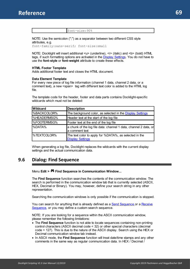
69
Docklight Scripting V2.3 User Manual 12/2019 Copyright 2019 Flachmann und Heggelbacher GbR
Reference
font-size:90%
NOTE: Use the semicolon (";") as a separator between two different CSS styleattributes, e.g. font-family:sans-serif; font-size:small
NOTE: Docklight will insert additional <u> (underline), <i> (italic) and <b> (bold) HTMLtags, if such formatting options are activated in the Display Settings. You do not have touse the font-style or font-weight attribute to create these effects.
HTML Footer TemplateAdds additional footer text and closes the HTML document.
Data Element TemplateFor every new piece of log file information (channel 1 data, channel 2 data, or acomment text), a new <span> tag with different text color is added to the HTML logfile.
The template code for the header, footer and data parts contains Docklight-specificwildcards which must not be deleted:
Wildcard Description
%BACKCOLOR% The background color, as selected in the Display Settings
%HEADERMSG% Header text at the start of the log file
%FOOTERMSG% Footer text at the end of the log file
%DATA% a chunk of the log file data: channel 1 data, channel 2 data, ora comment text
%TEXTCOLOR% The text color to apply for %DATA%, as selected in theDisplay Settings
When generating a log file, Docklight replaces the wildcards with the current displaysettings and the actual communication data.
9.6 Dialog: Find Sequence
Menu Edit > Find Sequence in Communication Window...
The Find Sequence function searches the contents of the communication window. Thesearch is performed in the communication window tab that is currently selected (ASCII,HEX, Decimal or Binary). You may, however, define your search string in any otherrepresentation.
Searching the communication windows is only possible if the communication is stopped.
You can search for anything that is already defined as a Send Sequence or a ReceiveSequence, or you may define a custom search sequence.
NOTE: If you are looking for a sequence within the ASCII communication window,please remember the following limitations: · The Find Sequence function is not able to locate sequences containing non-printing
control characters (ASCII decimal code < 32) or other special characters (decimalcode > 127). This is due to the nature of the ASCII display. Search using the HEX orDecimal communication window tab instead.
· In ASCII mode, the Find Sequence function will treat date/time stamps and any othercomments in the same way as regular communication data. In HEX / Decimal /

70
Docklight Scripting V2.3 User Manual 12/2019 Copyright 2019 Flachmann und Heggelbacher GbR
Reference
Binary mode, all additional information is ignored as long as it does not look like acharacter byte value.
9.7 Dialog: Send Sequence Parameter
Type in one or several value(s) for a Send Sequence with wildcards here. As with theEdit Send/Receive Sequence dialog, you may use control character shortcuts orclipboard functions. Parameter No.A Send Sequence can contain any number of wildcards. Each set of consecutivewildcards is considered a separate parameter. The value for each parameter is enteredseparately.
Minimum Characters RequiredFor each '?' wildcard exactly one character is required. Therefore, the minimum numberof characters required is equal to the number of '?' wildcards within one parameter.
NOTE: While the Send Sequence Parameter dialog is shown, all serial communicationis paused. Docklight does not receive any data and does not send any (periodical)Send Sequences.
9.8 Dialog: Project Settings - Communication
Menu Tools > Project Settings... | Communication
Communication Mode
Send/ReceiveDocklight acts both as transmitter and receiver of serial data. This mode is used whenTesting the functionality or the protocol implementation of a serial device or simulating aserial device. Naming conventions: The received data (RX) will be displayed and processed as"Channel 1", the transmitted data (TX) will be displayed as "Channel 2". MonitoringDocklight receives serial data on two different communication channels. This mode isused, for example, when Monitoring the communication between two devices.Naming conventions: The serial data from device 1 is "Channel 1", the data from device2 is "Channel 2".
Communication Channels - Serial COM ports, Docklight TAP/VTP, networkTCP/UDP, HID, Named PipesIn Docklight Scripting, a communication channel can be configured as· Serial COM port (RS232, RS422 or RS485), · TAP port for Docklight Tap monitoring· VTP port for Docklight Tap Pro or Tap 485 monitoring· Network communication socket for TCP or UDP· HID connections for USB or Bluetooth devices· Named Pipes client
The following settings can be used:
Setting / Examples Description
COMxxx The channel is connected to a serial COM port.
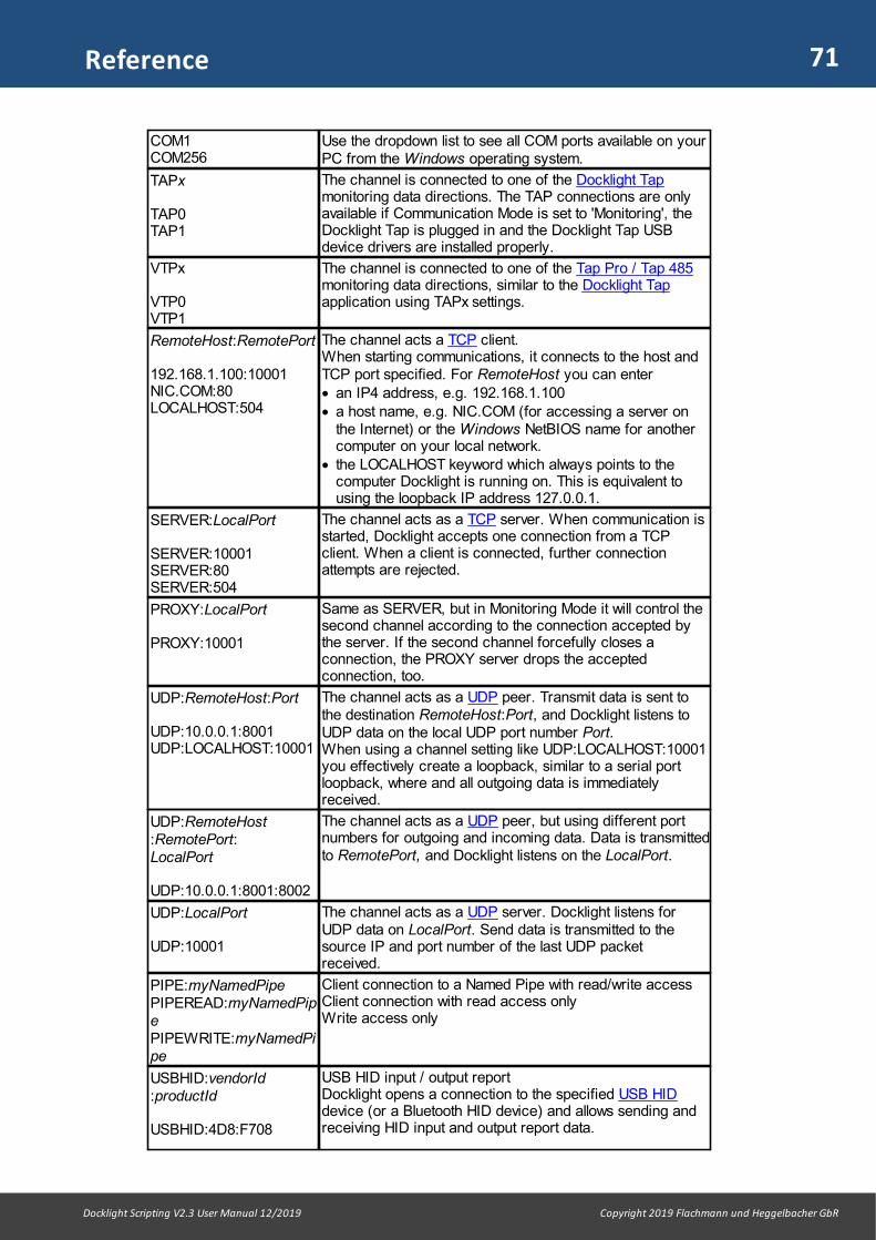
71
Docklight Scripting V2.3 User Manual 12/2019 Copyright 2019 Flachmann und Heggelbacher GbR
Reference
COM1COM256
Use the dropdown list to see all COM ports available on yourPC from the Windows operating system.
TAPx
TAP0TAP1
The channel is connected to one of the Docklight Tapmonitoring data directions. The TAP connections are onlyavailable if Communication Mode is set to 'Monitoring', theDocklight Tap is plugged in and the Docklight Tap USBdevice drivers are installed properly.
VTPx
VTP0VTP1
The channel is connected to one of the Tap Pro / Tap 485monitoring data directions, similar to the Docklight Tapapplication using TAPx settings.
RemoteHost:RemotePort
192.168.1.100:10001NIC.COM:80LOCALHOST:504
The channel acts a TCP client. When starting communications, it connects to the host andTCP port specified. For RemoteHost you can enter· an IP4 address, e.g. 192.168.1.100· a host name, e.g. NIC.COM (for accessing a server on
the Internet) or the Windows NetBIOS name for anothercomputer on your local network.
· the LOCALHOST keyword which always points to thecomputer Docklight is running on. This is equivalent tousing the loopback IP address 127.0.0.1.
SERVER:LocalPort
SERVER:10001SERVER:80SERVER:504
The channel acts as a TCP server. When communication isstarted, Docklight accepts one connection from a TCPclient. When a client is connected, further connectionattempts are rejected.
PROXY:LocalPort
PROXY:10001
Same as SERVER, but in Monitoring Mode it will control thesecond channel according to the connection accepted bythe server. If the second channel forcefully closes aconnection, the PROXY server drops the acceptedconnection, too.
UDP:RemoteHost:Port
UDP:10.0.0.1:8001UDP:LOCALHOST:10001
The channel acts as a UDP peer. Transmit data is sent tothe destination RemoteHost:Port, and Docklight listens toUDP data on the local UDP port number Port. When using a channel setting like UDP:LOCALHOST:10001you effectively create a loopback, similar to a serial portloopback, where and all outgoing data is immediatelyreceived.
UDP:RemoteHost:RemotePort:LocalPort
UDP:10.0.0.1:8001:8002
The channel acts as a UDP peer, but using different portnumbers for outgoing and incoming data. Data is transmittedto RemotePort, and Docklight listens on the LocalPort.
UDP:LocalPort
UDP:10001
The channel acts as a UDP server. Docklight listens forUDP data on LocalPort. Send data is transmitted to thesource IP and port number of the last UDP packetreceived.
PIPE:myNamedPipePIPEREAD:myNamedPipePIPEWRITE:myNamedPipe
Client connection to a Named Pipe with read/write accessClient connection with read access onlyWrite access only
USBHID:vendorId:productId
USBHID:4D8:F708
USB HID input / output report Docklight opens a connection to the specified USB HIDdevice (or a Bluetooth HID device) and allows sending andreceiving HID input and output report data.

72
Docklight Scripting V2.3 User Manual 12/2019 Copyright 2019 Flachmann und Heggelbacher GbR
Reference
(or use USB Device Path)USBHID:\\?\hid#vid_04d8&pid_...
The Docklight communication display is report-based: Eachinput report generates a new Docklight time stamp andprints the original HID report data, including the input reportID as the first byte, if > 0.
USBHID:vendorId:productId:P
USBHID:4D8:F708:P
USB HID access, protocol based.Only the actual payload data is displayed, without theleading Input Report ID byte and/or trailing zero bytes. Timestamps are generated according to the usual time stamprules, not before every report.
USBHID:vendorId:productId:I
USBHID:4D8:F708:I
USB HID access, but with variable output report ID as partof your Send Sequence data. In this mode, all SendSequence definitions require an extra byte at the start of thesequence, which sets the actual Output Report ID to use.
USBHID:vendorId:productId:[P],outputID,outputPayloadSize
USBHID:4D8:F708:,1,63USBHID:4D8:F708:P,2
USB HID extended syntax:outputID: if specified, use this Output Report ID, instead ofthe default zerooutputPayloadSize: if specified, override the report lengthand ignore the value Windows reports viaHID_CAPS.OutputReportByteLength
PIPE:myNamedPipePIPEREAD:myNamedPipePIPEWRITE:myNamedPipe
Client connection to a Named Pipe with read/write accessClient connection with read access onlyWrite access only
Monitoring Mode - Channel Combinations And Their ApplicationsIn Monitoring Mode, two communication channels are available, which can be set upindividually. This allows Docklight Scripting to be used in a large number of differentapplications and test environments. Below is a list of typical channel combinations:
CommunicationChannel Settings
ExampleSettings
Application
Ch1: COM PortCh2: COM Port
COM1COM2
Monitoring Serial Communications Between TwoDevices using a Docklight Monitoring Cable
Ch1: DocklightTapCh2: DocklightTap
TAP0TAP1
Monitoring Serial Communications Between TwoDevices using a Docklight Tap
Ch1: Tap Pro or485Ch2: Tap Pro or485
VTP0VTP1
Monitoring Serial Communications Between TwoDevices using a Docklight Tap Pro or Docklight Tap485
Ch1: COM Port Ch2: TCP Server
COM1SERVER:10001
Emulating a Serial Device Server. A client canconnect to the Docklight server on port 10001 andtalk to the serial device connected on COM1.
Ch1: TCP ClientCh2: TCP Server
10.0.0.1:502SERVER:502
Monitoring a Client/Server TCP Connection whereDocklight acts as a gateway between the two sides.
Ch1: UDP PeerCh2: UDP Peer
UDP:10.0.0.1:8001
UDP:10.0.0.2:8002
Monitoring and forwarding a UDP transmission,similar to the TCP example above. Note that foreach channel you need to specify a different UDPport, because each channel needs to listen on itsown separate port number.

73
Docklight Scripting V2.3 User Manual 12/2019 Copyright 2019 Flachmann und Heggelbacher GbR
Reference
COM Port Settings (COM, TAP and VTP channels only)
Baud RateChoose a standard baud rate from the dropdown list, or use a non-standard baud rateby typing any integer number between 110 and 9999999.
NOTE: Non-standard baud rates may not work correctly on all COM ports, dependent onthe capabilities of your COM port's hardware UART chip. You will receive no warning, ifany non-standard rate cannot be applied.
NOTE: Although Docklight's Project Settings allow you to specify baud rates up to 9MBaud, this does not mean Docklight is able to handle this level of throughputcontinuously. The average data throughput depends very much on your PC'sperformance and the Docklight display settings. See also How to Increase theProcessing Speed.
NOTE: There are many COM ports drivers and applications that do not use actualRS232/422 or 485 transmission, and do not require any of the RS232 communicationparameters. In some cases such COM port drivers even return an error when trying toset the RS232 parameters, so Docklight would fail to open the COM channel. Use theBaud Rate setting None for these applications.
Data Bits and Stop BitsSpecify the number of data bits and stop bits here. As with the baud rate, some of theavailable settings may not be supported by the COM port device(s) on your PC.
Tap 485 Sign. Level. The Docklight Tap Pro / Tap 485 support additional voltage levels, besides the standardRS232 voltages:· RS485/422 - the differential voltage levels for RS485 and RS422 bus applications. · Inverted - Inverted RS232/TTL mode, where the mark state (or logical 1) is the
positive voltage, and the space state (logical 0) is the negative voltage or zero volts.
Parity All common parity check options are available here. (The settings 'Mark' and 'Space' willprobably not be used in practical applications. 'Mark' specifies that the parity bit alwaysis 1, 'Space' that the parity bit is always 0, regardless of the character transmitted.)
Parity Error CharacterThis is the character that replaces an invalid character in the data stream whenever aparity error occurs. You should specify an ASCII character (printing or non-printing)that does not usually appear within your serial data stream. Characters may be definedby entering the character itself or entering its decimal ASCII code (please enter at leasttwo digits).
NOTE: Choose "(ignore)" for the Parity Error Character if you need to transmit/receivethe parity bit but Docklight should preserve all incoming characters, even when theparity bit is wrong. This is useful for applications where a 9th bit is used for addressingpurposes and not for error checking.
Using Baud Rate Scan - VTP channels only
Docklight Tap Pro / Tap 485 devices offer a baud rate scan / autodetect mode. Toactivate baud rate scan, choose None from the Baud Rate setting and close the
Project Settings dialog. Now start the communication using menu Run > Startcommunication (F5). The Docklight Tap Pro / Tap 485 now scans the communicationindependently in both directions. If serial data could be detected in either data direction,
74
Docklight Scripting V2.3 User Manual 12/2019 Copyright 2019 Flachmann und Heggelbacher GbR
Reference
the most probable settings are displayed as comments in the Communication Window.They are also are noted in the communications status bar under the main toolbar.
NOTE: The accuracy of this autodetection feature depends on the actual data streampresent during the scan. A continuous stream of highly random data leads to highdetection accuracy, while small transfers of individual bytes or repeating patterns maylead to wrong baud rates, data bit or parity guesses.
9.9 Dialog: Project Settings - Flow Control
Menu Tools > Project Settings... | Flow Control
Used to specify additional hardware or software flow control settings for serialcommunications in Docklight Send/Receive Mode.
Flow Control Support
OffNo hardware or software flow control mechanism is used. RTS and DTR are enabledwhen the COM port is opened.
ManualUse this mode to control the RTS and DTR signals manually and display the currentstate of the CTS, DSR, DCD and RI lines. If flow control is set to "Manual", an additionalstatus element is displayed in the Docklight main window. You may toggle the RTS andDTR lines by double clicking on the corresponding indicator.
NOTE: Flow control signals are not treated as communication data and will not bedisplayed in the communication window or logged to a file.
Hardware Handshaking, Software HandshakingSupport for RTS/CTS hardware flow control and XON/XOFF software flow control.These are expert settings rarely required for recent communication applications.
RS485 Transceiver ControlSome RS232-to-RS485 converters require manual RTS control, i.e. the RS232 device(PC) tells the converter when it should enable its RS485 driver for transmission. If youchoose "RS485 Transceiver Control", the COM port sets RTS to High before transmittingthe first character of a Send Sequence, and resets it to Low after the last character hasbeen transmitted.
NOTE: Many USB-to-Serial converters or virtual COM port drivers do not implement theWindows RTS_CONTROL_TOGGLE mode properly. If you experience problems withRS485 Transceiver Control, try using a PC with an on-board COM interface or astandard PCI COM card.
9.10 Dialog: Project Settings - Communication Filter
Menu Tools > Project Settings... | Communication Filter
Contents FilterUse this option if you do not need to see the original communication data on the serialline and only require the additional comments inserted by a Receive Sequence. This isuseful for applications with high data throughput, where most of the data is irrelevant fortesting and you only need to watch for very specific events. These events (and relateddisplay output) can be defined using Receive Sequences.

75
Docklight Scripting V2.3 User Manual 12/2019 Copyright 2019 Flachmann und Heggelbacher GbR
Reference
Channel AliasThis allows you to re-label the two Docklight data directions according to your specificuse case. E.g. [Docklight] / [Device] instead of [TX] / [RX]. Or [Master] / [Slave] insteadof [TAP0] / [TAP1].
9.11 Dialog: Options
Menu Tools > Options...
Display
Formatted Text Output (Rich Text Format)used for setting the appearance of the Docklight communication window. The twodifferent serial data streams, "Channel 1" and "Channel 2", may be displayed usingdifferent colors and styles. The standard setting uses different colors for the twochannels, but using different font styles (e.g. Italics for "Channel 2") is also possible.You may also choose the overall font size here.
NOTE: If you change the font size, the communication window contents will be deleted.For all other changes, Docklight will try to preserve the display contents.
Plain Text Output (faster display, but no colors & fonts)The formatted text output is similar to a word processor and consumes a considerableamount of CPU time. It also requires frequent memory allocation and deallocation whichmight decrease your PC performance. So if you are monitoring a high-speedcommunication link, but still want to keep an eye on the serial data transferred, try usingthe "Plain Text Output" format.
Control Characters (ASCII 0 - 31)For communication data containing both printing ASCII text as well as non-printingcontrol characters, it is sometimes helpful to see the names of the occurring controlcharacters in the ASCII mode display window. Docklight provides an optional displaysettings to allow this. You can also suppress the control characters (except CR and LF)for cases when this would clutter your display.
Display Modes
Communication Window ModesBy default, Docklight will display four representations of the serial data streams: ASCII,HEX, Decimal and Binary. You may deactivate some of these modes to increaseDocklight's overall performance. For example, the Binary representation of the data israrely required. Disabling Binary mode for the communication window will considerablyincrease processing speed. Even when turned off for the communication window,logging in all formats is still possible.
See also the Plain Text Output option above.
Date/Time Stamps
Adding a Date/Time StampDocklight adds a date/time stamp to all data that is transmitted or received. You maychoose to insert this date/time stamp into the communication window and the log filewhenever the data flow direction changes between Channel 1 and Channel 2.
For applications where the data flow direction does not change very often, you maywant to have additional date/time stamps at regular time intervals. For this, activate theClock - additional date/time stamp... option then and choose a time interval.
76
Docklight Scripting V2.3 User Manual 12/2019 Copyright 2019 Flachmann und Heggelbacher GbR
Reference
On a half duplex line (e.g. 2 wire RS485), changes in data direction are difficult todetect. Still, in most applications there will be a pause on the communication bus beforea new device starts sending. Use the Pause detection... option to introduce additionaltime stamps and make the pauses visible in your communication log.
Date/Time FormatDocklight offers time stamps with a resolution of up to 1/1000 seconds (1 millisecond).For compatibility to earlier Docklight versions (V1.8 and smaller), 1/100 seconds isavailable, too.
NOTE: The resulting time tagging accuracy can be considerably different, e.g. 10-20milliseconds only. The actual accuracy depends on your serial communicationsequipment, your PC configuration, the Docklight Display Settings (see above) and theDocklight Expert Options. See the section How to Obtain Best Timing Accuracy fordetails.
Control Characters Shortcuts
Here you can define your own keyboard shortcuts for ASCII Control Characters (ASCIIcode < 32), or for any character code > 126. Keyboard shortcuts can be used withinthe following Docklight dialogs and functions· Dialog: Edit Send Sequence· Dialog: Edit Receive Sequence· Dialog: Find Sequence· Dialog: Send Sequence Parameter· Keyboard Console
For each character from decimal code 0 to 31 and from 127 to 255, you can define akeyboard combination to insert this character into a sequence (Shortcut). You mayalso define a letter which is used to display this control character when editing asequence in ASCII mode (Editor).
Double click to change the value of a Shortcut or Editor field.
Predefined shortcuts are:Ctrl+Enter for carriage return / <CR> / decimal code 13Ctrl+Shift+Enter for line feed / <LF> / decimal code 10
9.12 Dialog: Expert Options
Menu Tools > Expert Options...
Expert Options are additional settings for specialized applications with additionalrequirements (e.g. high time tagging accuracy).
Performance
Communication Driver Mode
Use External / High Priority Process mode to work around a common problem forany Windows user mode application: unspecified delays and timing inaccuracies canbe introduced by the Windows task/process scheduling, especially if you are runningother applications besides Docklight.
External / High Priority Process mode is recommended for high accuracy / lowlatency monitoring using the Docklight Tap.

77
Docklight Scripting V2.3 User Manual 12/2019 Copyright 2019 Flachmann und Heggelbacher GbR
Reference
NOTE: For even higher and guaranteed time tagging accuracy, use the Docklight TapPro / Tap 485 accessories. Their accuracy does not depend on Windows and driverlatencies, and High Priority Process mode is not required for Tap Pro and Tap 485applications.
In External / High Priority Process mode, the data collection in Docklight becomes aseparate Windows process with Realtime priority class. It will be executed with higherpriority than any other user application or additional application software such asInternet Security / Antivirus. For best results Docklight needs to be Run asadministrator. Otherwise the data collection process will run with the maximumpermitted priority, but not "Realtime class".
External / High Priority Process mode must be used with care, especially when youintend to monitor a high-speed data connection with large amounts of data. The PCmight become unresponsive to user input. To resolve such a situation, simply "pull theplug": First disconnect the data connections or the monitoring cable to bring down the
CPU load and restore the responsiveness. Then choose Stop communication inDocklight.
NOTE: See the section How to Obtain Best Timing Accuracy for some backgroundinformation on timing accuracy.
Docklight Monitoring Mode
When Monitoring Serial Communications Between Two Devices, all received data fromone COM port is re-sent on the TX channel of the opposite COM port by default ("DataForwarding"). This is intended for special applications that require routing the serialdata traffic through Docklight using standard RS232 cabling.
Use the No Data Forwarding Expert Option for applications with two serial COM portswhere you need to avoid that any TX data is sent. This can be used to improveperformance when using a Docklight Monitoring Cable, or to work around problemscaused with unstable serial device drivers.
For Docklight Tap applications (e.g. using Communication Channel TAP0 / TAP1), the'Data Forwarding' setting has no effect. The Docklight Tap is accessed in read-onlymode always, and no data is forwarded.
9.13 Keyboard Console
The Keyboard Console tool allows you to send keyboard input directly to the serial port.
It can be activated using the menu Tools > Keyboard Console On. The keyboardconsole is only available for communication mode Send/Receive.
After activating the keyboard console, click in the communication window and typesome characters.
Docklight will transmit the characters directly through the selected serial port. Thecommunication window will display the characters the same way it does a SendSequence.
NOTE: The Keyboard Console tool supports pasting and transmitting a charactersequence from the clipboard, using Ctrl + V. This is similar to pasting clipboard datainside the Edit Send Sequence Dialog. Clipboard contents that exceeds the maximumsequence size of 1024 characters gets truncated.
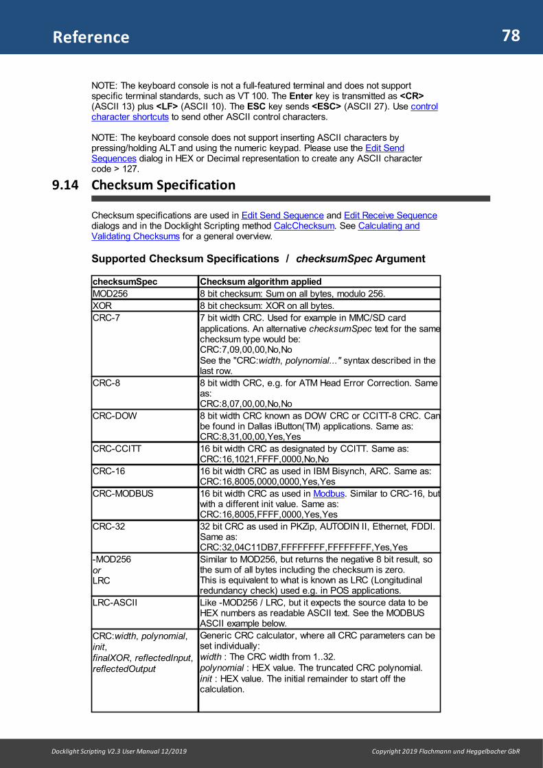
78
Docklight Scripting V2.3 User Manual 12/2019 Copyright 2019 Flachmann und Heggelbacher GbR
Reference
NOTE: The keyboard console is not a full-featured terminal and does not supportspecific terminal standards, such as VT 100. The Enter key is transmitted as <CR>(ASCII 13) plus <LF> (ASCII 10). The ESC key sends <ESC> (ASCII 27). Use controlcharacter shortcuts to send other ASCII control characters.
NOTE: The keyboard console does not support inserting ASCII characters bypressing/holding ALT and using the numeric keypad. Please use the Edit SendSequences dialog in HEX or Decimal representation to create any ASCII charactercode > 127.
9.14 Checksum Specification
Checksum specifications are used in Edit Send Sequence and Edit Receive Sequencedialogs and in the Docklight Scripting method CalcChecksum. See Calculating andValidating Checksums for a general overview.
Supported Checksum Specifications / checksumSpec Argument
checksumSpec Checksum algorithm applied
MOD256 8 bit checksum: Sum on all bytes, modulo 256.
XOR 8 bit checksum: XOR on all bytes.
CRC-7 7 bit width CRC. Used for example in MMC/SD cardapplications. An alternative checksumSpec text for the samechecksum type would be: CRC:7,09,00,00,No,NoSee the "CRC:width, polynomial..." syntax described in thelast row.
CRC-8 8 bit width CRC, e.g. for ATM Head Error Correction. Sameas:CRC:8,07,00,00,No,No
CRC-DOW 8 bit width CRC known as DOW CRC or CCITT-8 CRC. Canbe found in Dallas iButton(TM) applications. Same as:CRC:8,31,00,00,Yes,Yes
CRC-CCITT 16 bit width CRC as designated by CCITT. Same as:CRC:16,1021,FFFF,0000,No,No
CRC-16 16 bit width CRC as used in IBM Bisynch, ARC. Same as:CRC:16,8005,0000,0000,Yes,Yes
CRC-MODBUS 16 bit width CRC as used in Modbus. Similar to CRC-16, butwith a different init value. Same as:CRC:16,8005,FFFF,0000,Yes,Yes
CRC-32 32 bit CRC as used in PKZip, AUTODIN II, Ethernet, FDDI.Same as:CRC:32,04C11DB7,FFFFFFFF,FFFFFFFF,Yes,Yes
-MOD256orLRC
Similar to MOD256, but returns the negative 8 bit result, sothe sum of all bytes including the checksum is zero.This is equivalent to what is known as LRC (Longitudinalredundancy check) used e.g. in POS applications.
LRC-ASCII Like -MOD256 / LRC, but it expects the source data to beHEX numbers as readable ASCII text. See the MODBUSASCII example below.
CRC:width, polynomial,init, finalXOR, reflectedInput,reflectedOutput
Generic CRC calculator, where all CRC parameters can beset individually:width : The CRC width from 1..32.polynomial : HEX value. The truncated CRC polynomial.init : HEX value. The initial remainder to start off thecalculation.

79
Docklight Scripting V2.3 User Manual 12/2019 Copyright 2019 Flachmann und Heggelbacher GbR
Reference
finalXor : HEX value. Apply an XOR operation on theresulting remainder before returning it to the user.reflectedInput : Yes = Reflect the data bytes (MSB becomesLSB), before feeding them into the algorithm.reflectedOutput : Yes = Reflect the result after completingthe algorithm. This takes places before the final XORoperation.
Remarks
Each of the predefined CRC algorithms (CRC-8, CRC-CCITT, ...) can be replaced by aspecification string for the generic CRC computation (CRC:8,07,00...) as describedabove. We have carefully tested and cross-checked our implementations againstcommon literature and resources as listed in the CRC Glossary.
Unfortunately there are a lot of CRC variations and algorithms around, and choosing(not to mention: understanding) the right CRC flavor can be a rather difficult job. A goodway to make sure your CRC calculation makes sense is to run it over an ASCII teststring of "123456789". This is the most commonly used testing string, and manyspecifications will refer to this string and provide you the correct checksum the CRCshould return when applied on this string.
Checksums in Edit Send Sequence / Edit Receive Sequence
In the Checksum tab, choose one of the predefined definition strings from the drop-down list, or type in your own definition in the following format:
[ (startPos, len) ] checksumSpec [A or L] [@ targetPos] [ # optional user comment]
with anything inside [ ] being an optional part.
Part Description
checksumSpec Required. String that specifies the checksum algorithm and itsparameters, according to the checksumSpec Format table above.
(startPos, len)e.g. (1, 4)
Optional. Start and length of the character area that is used tocalculate the checksum. By default everything before the checksumresult is used.
A Optional. If used, the resulting checksum value is converted into aHEX number as readable ASCII text. See the MODBUS ASCIIexample below.
L Optional. Little Endian - the resulting checksum value is stored with theleast significant byte (LSB) first. Default is Big Endian / MSB first.
@ targetPos
e.g. @ -4
Optional. Specifies the first character position for storing the resultingchecksum value. By default Docklight writes the checksum result to the last sequencedata positions, unless you have specified "A" for ASCII result. In thiscase, the results is stored one character before the end, so there isstill space for a "end of line" character, typically a CR as in ModbusASCII.
# comment You can type in a comment about this checksum specification
Remarks
startPos, len and targetPos support negative values, too, as a way to specify positionsrelative to the end of the sequence and not relative to the start of the sequence.Examples: startPos is -4 : start calculating at the 4th character from the end.len is -1 : use everything until the end of the sequence.
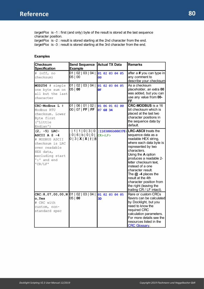
80
Docklight Scripting V2.3 User Manual 12/2019 Copyright 2019 Flachmann und Heggelbacher GbR
Reference
targetPos is -1 : first (and only) byte of the result is stored at the last sequencecharacter position.targetPos is -2 : result is stored starting at the 2nd character from the end.targetPos is -3 : result is stored starting at the 3rd character from the end.
Examples
ChecksumSpecification
Send SequenceExample
Actual TX Data Remarks
# (off, nochecksum)
01 | 02 | 03 | 04 |05 | 00
01 02 03 04 0500
after a # you can type inany comment todescribe your checksum
MOD256 # simpleone byte sum onall but the lastcharacter
01 | 02 | 03 | 04 |05 | 00
01 02 03 04 050F
As a checksumplaceholder, an extra 00was added, but you canuse any value from 00-FF.
CRC-Modbus L #Modbus RTUchecksum. LowerByte first('LittleEndian')
01 | 06 | 01 | 02 |00 | 07 | FF | FF
01 06 01 02 0007 68 34
CRC-MODBUS is a 16bit checksum which isplaced at the last twocharacter positions inthe sequence data bydefault.
(2, -5) LRC-ASCII A @ -4 # MODBUS ASCIIchecksum is LRCover readableHEX data,excluding start':' and end'CR/LF'
: | 1 | 1 | 0 | 3 | 0| 0 | 6 | b | 0 | 0 |0 | 3 | X | X | r | n
:1103006b00037E<CR><LF>
LRC-ASCII treats thesequence data as areadable HEX string,where each data byte isrepresented by twocharacters. Using the A optionproduces a readable 2-letter checksum text,instead of a onecharacter result.The @ -4 places theresult at the 4thcharacter position fromthe right (leaving thetrailing CR / LF intact).
CRC:8,07,00,00,No,Yes # CRC withcustom, non-standard spec
01 | 02 | 03 | 04 |05 | 00
01 02 03 04 053D
Rare or custom CRCsflavors can be calculatedby Docklight, but youneed to know therequired CRCcalculation parameters.For more details see theresources listed in theCRC Glossary.

Reference (Scripting)

82
Docklight Scripting V2.3 User Manual 12/2019 Copyright 2019 Flachmann und Heggelbacher GbR
Reference (Scripting)
10 Reference (Scripting)
10.1 VBScript Basics
If you already know Visual Basic® or Visual Basic® for Applications (VBA), VBScriptwill be very familiar. Have a look at the definitions and examples listed below. For gettingstarted, try some of the following examples by copying & pasting the code into the scripteditor window and running the script. Docklight Scripting also comes with a number ofsample scripts for you to try out.
This chapter introduces some basic VBScript functions and features. For a completereference, please see the original documentation from Microsoft® at the followinglocations:· Visual Basic Scripting Edition (or go to www.microsoft.com and search for
"VBScript") · VBScript User's Guide· VBScript Language Reference.
TIP: Use the ScriptEngine function to find out which version of VBScript is installed onyour computer.
NOTE: Docklight Scripting executes the VBScript code in "safe mode" (safe subset)and disallows potentially harmful actions. For example, creating a"FileSystemObject" (file I/O) is one of the actions disallowed in the VBScript safesubset. The Docklight script will abort with an error message. Please contact our e-mailsupport if you have special requirements and need to use "unsafe" VBScriptstatements. By popular request, file I/O is now easily possible using Docklight's FileInput/ FileOutput objects.
Docklight-Specific Features
· Docklight Script Commands - The DL Object· Docklight OnSend / OnReceive event procedures· Docklight FileInput / FileOutput Object for Reading and Writing Files
VBScript Basic Features by Categories
· Control Structures (Decision Structures, Loop Structures)· Variables, Arrays, Constants and Data Types· Operators· Date/Time Functions· Miscellaneous
VBScript Basic Features in Alphabetical Order
· Date Function· Day Function· Do Until ...Loop· Do...Loop While· For...Next· Hour Function· If...Then· If...Then...Else· InputBox Function

83
Docklight Scripting V2.3 User Manual 12/2019 Copyright 2019 Flachmann und Heggelbacher GbR
Reference (Scripting)
· LBound Function· Minute Function· Month Function· Now Function· ScriptEngine Function· Second Function· Select Case· Time Function· Timer Function· UBound Function· While...Wend· Year Function
10.1.1 Copyright Notice
The following sections of the "VBScript Basics" chapter are based on the Microsoft®Windows Script V5.6 Documentation help file Script56.CHM. For this help file, thefollowing copyright notice applies: "© 2001 Microsoft® Corporation. All rightsreserved."
The usage of Microsoft® copyrighted material is according to the Microsoft® "TenPercent Rule" (see http://www.microsoft.com/permission).
10.1.2 Control Structures
VBScript control structures allow you to control the flow of your script's execution. Tolearn more about specific control structures, see the following topics:
· Decision Structures An introduction to decision structures used for branching. · Loop Structures An introduction to loop structures used to repeat processes.
10.1.2.1 Decision Structures
· If...Then
Use an If...Then structure to execute one or more statements conditionally. You canuse either a single-line syntax or a multiple-line block syntax:
If condition Then statement
If condition ThenstatementsEnd If
The condition is usually a comparison. If condition is True, VBScript executes all thestatements following the Then keyword. You can use either single-line or multiple-linesyntax to execute just one statement conditionally (these two examples are equivalent):
If anyDate < Now Then anyDate = Now
If anyDate < Now Then anyDate = NowEnd If

84
Docklight Scripting V2.3 User Manual 12/2019 Copyright 2019 Flachmann und Heggelbacher GbR
Reference (Scripting)
Notice that the single-line form of If...Then does not use an End If statement. If youwant to execute more than one line of code when condition is True, you must use themultiple-line block If...Then...End If syntax.
· If...Then...Else
Use an If...Then...Else block to define several blocks of statements, one of which willexecute:
If condition1 Then[statementblock-1][ElseIf condition2 Then[statementblock-2]] ...[Else[statementblock-n]]End If
· Select Case
VBScript provides the Select Case structure as an alternative to If...Then...Else forselectively executing one block of statements from among multiple blocks ofstatements. A Select Case statement provides capability similar to the If...Then...Elsestatement, but it makes code more readable when there are several choices.
' ExampleSelect Case Weekday(now) Case 2 DL.AddComment "Monday" Case 3 DL.AddComment "Tuesday" Case 4 DL.AddComment "Wednesday" Case 5 DL.AddComment "Thursday" Case 6 DL.AddComment "Friday" Case Else DL.AddComment "Weekend!" End Select
10.1.2.2 Loop Structures
· Do Until ...Loop
'Example Do Until DefResp = vbNo MyNum = Int (6 * Rnd + 1) ' Generate a random integerbetween 1 and 6.
DefResp = MsgBox (MyNum & " Do you want another number?",vbYesNo)
Loop
· Do...Loop While
'Example
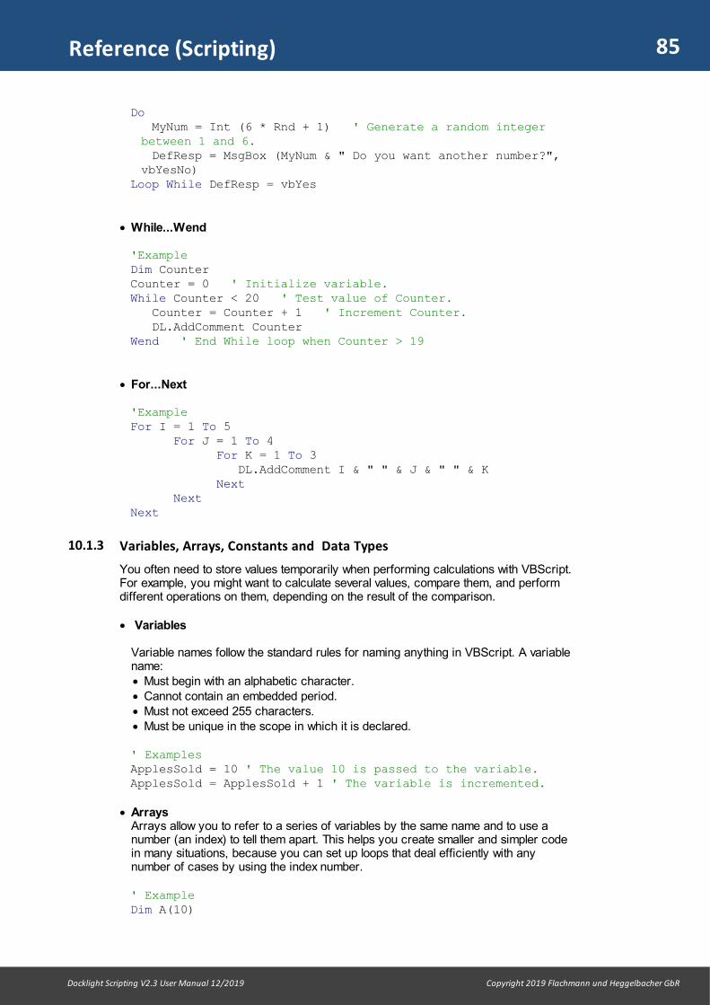
85
Docklight Scripting V2.3 User Manual 12/2019 Copyright 2019 Flachmann und Heggelbacher GbR
Reference (Scripting)
Do MyNum = Int (6 * Rnd + 1) ' Generate a random integerbetween 1 and 6.
DefResp = MsgBox (MyNum & " Do you want another number?",vbYesNo)
Loop While DefResp = vbYes
· While...Wend
'ExampleDim CounterCounter = 0 ' Initialize variable.While Counter < 20 ' Test value of Counter. Counter = Counter + 1 ' Increment Counter. DL.AddComment CounterWend ' End While loop when Counter > 19
· For...Next
'ExampleFor I = 1 To 5 For J = 1 To 4 For K = 1 To 3 DL.AddComment I & " " & J & " " & K Next NextNext
10.1.3 Variables, Arrays, Constants and Data Types
You often need to store values temporarily when performing calculations with VBScript.For example, you might want to calculate several values, compare them, and performdifferent operations on them, depending on the result of the comparison.
· Variables
Variable names follow the standard rules for naming anything in VBScript. A variablename: · Must begin with an alphabetic character. · Cannot contain an embedded period. · Must not exceed 255 characters. · Must be unique in the scope in which it is declared.
' ExamplesApplesSold = 10 ' The value 10 is passed to the variable. ApplesSold = ApplesSold + 1 ' The variable is incremented.
· ArraysArrays allow you to refer to a series of variables by the same name and to use anumber (an index) to tell them apart. This helps you create smaller and simpler codein many situations, because you can set up loops that deal efficiently with anynumber of cases by using the index number.
' ExampleDim A(10)

86
Docklight Scripting V2.3 User Manual 12/2019 Copyright 2019 Flachmann und Heggelbacher GbR
Reference (Scripting)
A(0) = 256A(1) = 324A(2) = 100' ...A(10) = 55
LBound FunctionReturns the smallest available subscript for the indicated dimension of an array.
Syntax
LBound (arrayname [,dimension ] )
Part Description
arrayname Name of the array variable; follows standard variable namingconventions.
dimension Optional. Whole number indicating which dimension's lower boundis returned. Use 1 for the first dimension, 2 for the second, and soon. If dimension is omitted, 1 is assumed.
UBound FunctionReturns the largest available subscript for the indicated dimension of an array.
Syntax
UBound (arrayname [,dimension ] )
Part Description
arrayname Name of the array variable; follows standard variable namingconventions.
dimension Optional. Whole number indicating which dimension's lower boundis returned. Use 1 for the first dimension, 2 for the second, and soon. If dimension is omitted, 1 is assumed.
' ExampleDim A(100,3,4) UBound(A,1) ' returns 100 UBound(A,2) ' returns 3UBound(A,3) ' returns 4
· Constants
A Const statement can represent a mathematical or date/time quantity:
' ExampleConst conPi = 3.14159265358979
· Data Types
VBScript has only one data type called a Variant. A Variant is a special kind of datatype that can contain different kinds of information, depending on how it is used.Because Variant is the only data type in VBScript, it is also the data type returned byall functions in VBScript.
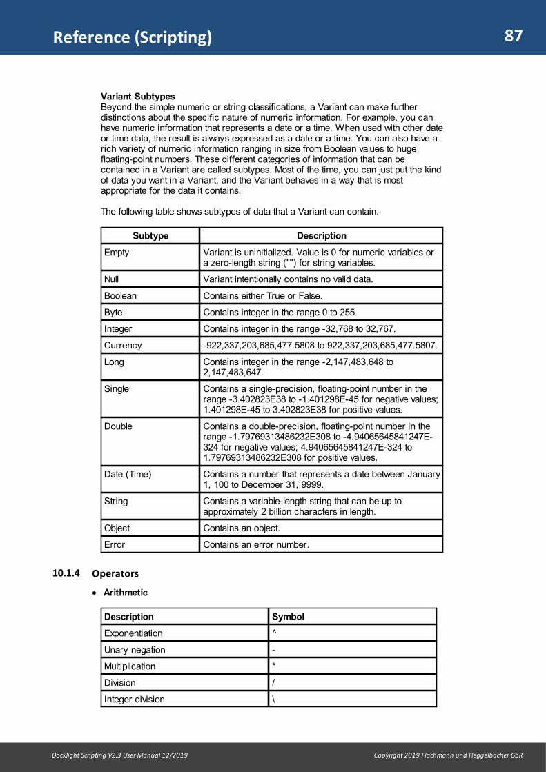
87
Docklight Scripting V2.3 User Manual 12/2019 Copyright 2019 Flachmann und Heggelbacher GbR
Reference (Scripting)
Variant SubtypesBeyond the simple numeric or string classifications, a Variant can make furtherdistinctions about the specific nature of numeric information. For example, you canhave numeric information that represents a date or a time. When used with other dateor time data, the result is always expressed as a date or a time. You can also have arich variety of numeric information ranging in size from Boolean values to hugefloating-point numbers. These different categories of information that can becontained in a Variant are called subtypes. Most of the time, you can just put the kindof data you want in a Variant, and the Variant behaves in a way that is mostappropriate for the data it contains.
The following table shows subtypes of data that a Variant can contain.
Subtype Description
Empty Variant is uninitialized. Value is 0 for numeric variables ora zero-length string ("") for string variables.
Null Variant intentionally contains no valid data.
Boolean Contains either True or False.
Byte Contains integer in the range 0 to 255.
Integer Contains integer in the range -32,768 to 32,767.
Currency -922,337,203,685,477.5808 to 922,337,203,685,477.5807.
Long Contains integer in the range -2,147,483,648 to2,147,483,647.
Single Contains a single-precision, floating-point number in therange -3.402823E38 to -1.401298E-45 for negative values;1.401298E-45 to 3.402823E38 for positive values.
Double Contains a double-precision, floating-point number in therange -1.79769313486232E308 to -4.94065645841247E-324 for negative values; 4.94065645841247E-324 to1.79769313486232E308 for positive values.
Date (Time) Contains a number that represents a date between January1, 100 to December 31, 9999.
String Contains a variable-length string that can be up toapproximately 2 billion characters in length.
Object Contains an object.
Error Contains an error number.
10.1.4 Operators
· Arithmetic
Description Symbol
Exponentiation ^
Unary negation -
Multiplication *
Division /
Integer division \
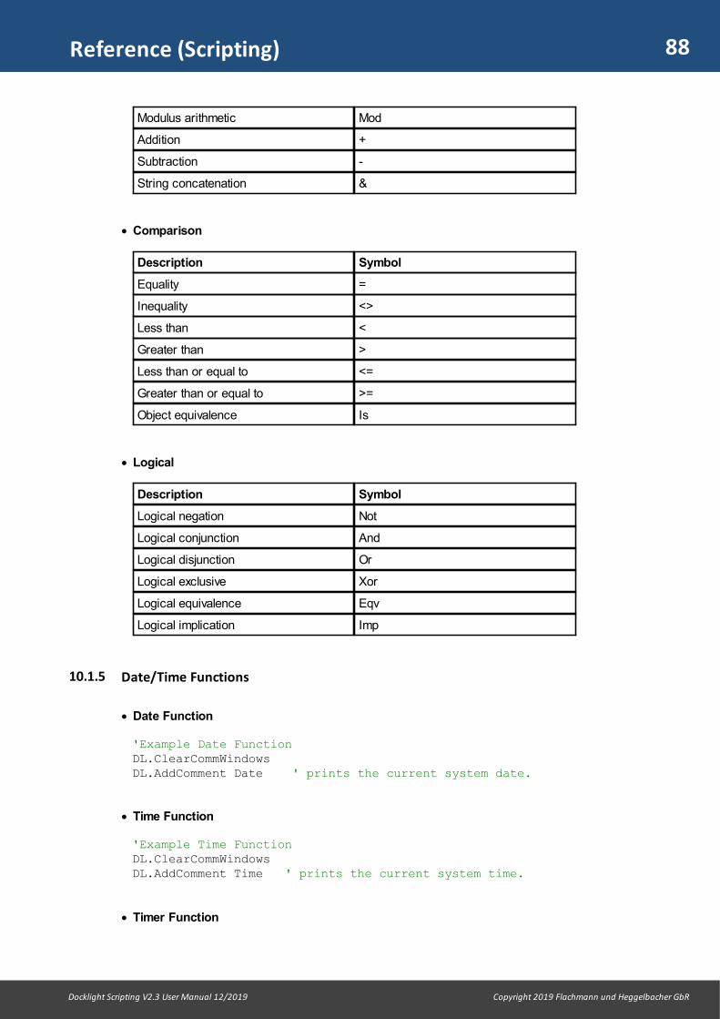
88
Docklight Scripting V2.3 User Manual 12/2019 Copyright 2019 Flachmann und Heggelbacher GbR
Reference (Scripting)
Modulus arithmetic Mod
Addition +
Subtraction -
String concatenation &
· Comparison
Description Symbol
Equality =
Inequality <>
Less than <
Greater than >
Less than or equal to <=
Greater than or equal to >=
Object equivalence Is
· Logical
Description Symbol
Logical negation Not
Logical conjunction And
Logical disjunction Or
Logical exclusive Xor
Logical equivalence Eqv
Logical implication Imp
10.1.5 Date/Time Functions
· Date Function
'Example Date FunctionDL.ClearCommWindowsDL.AddComment Date ' prints the current system date.
· Time Function
'Example Time FunctionDL.ClearCommWindowsDL.AddComment Time ' prints the current system time.
· Timer Function

89
Docklight Scripting V2.3 User Manual 12/2019 Copyright 2019 Flachmann und Heggelbacher GbR
Reference (Scripting)
'Example Timer Function'The Timer function returns the number of seconds that haveelapsed
'since 12:00 AM (midnight).StartTime = Timer For i = 1 To 1000Next DL.AddComment "Duration [milliseconds] = " & (Timer -StartTime) * 1000
· Now Function
'Example Now FunctionDim MyVar MyVar = Now ' MyVar contains the current date and time.
· Day Function
'Example Day FunctionDL.AddComment Day(Now)
· Month Function
'Example Month FunctionDL.AddComment Month(Now)
· Year Function
'Example Year FunctionDim MyDateMyDate = #December 7, 1968# ' Assign a date.DL.AddComment Year(MyDate)
· Hour Function
'Example Hour FunctionDL.AddComment Hour(Now)
· Minute Function
'Example Minute FunctionDL.AddComment Minute(Now)
· Second Function
'Example Second FunctionDL.AddComment Second(Now)

90
Docklight Scripting V2.3 User Manual 12/2019 Copyright 2019 Flachmann und Heggelbacher GbR
Reference (Scripting)
10.1.6 Miscellaneous
· InputBox Function
Displays a prompt in a dialog box, waits for the user to input text or click a button, andreturns the contents of the text box.
TIP: Use the Docklight-specific DL.InputBox2 method for a dialog box that alwaysappears on the same screen as the Docklight Scripting main window. Or see theDL.GetKeyState function on how to wait and react to keyboard or mouse input.
Syntax
InputBox (prompt[, title][, default][, xpos][, ypos][, helpfile, context])
Part Description
prompt Required. String expression displayed as the message in the dialogbox. The maximum length of prompt is approximately 1024 characters,depending on the width of the characters used. If prompt consists ofmore than one line, you can separate the lines using a carriage returncharacter (Chr(13)), a linefeed character (Chr(10)), or carriagereturn plus linefeed character combination (Chr(13) & Chr(10))between each line.
title Optional. String expression displayed in the title bar of the dialog box.If you omit title, the application name is placed in the title bar.
default Optional. String expression displayed in the text box as the defaultresponse if no other input is provided. If you omit default, the text boxis displayed empty.
xpos Optional. Numeric expression that specifies, in twips, the horizontaldistance of the left edge of the dialog box from the left edge of thescreen. If xpos is omitted, the dialog box is horizontally centered.
ypos Optional. Numeric expression that specifies, in twips, the verticaldistance of the upper edge of the dialog box from the top of thescreen. If ypos is omitted, the dialog box is vertically positionedapproximately one-third of the way down the screen.
helpfile Optional. String expression that identifies the Help file to use toprovide context-sensitive Help for the dialog box. If helpfile isprovided, context must also be provided.
context Optional. Numeric expression that identifies the Help context numberassigned by the Help author to the appropriate Help topic. If context isprovided, helpfile must also be provided.
'Example InputBox FunctionDim MyInputMyInput = InputBox("Please enter text", "My Title", "ExampleText")
DL.AddComment MyInput ' Add the current input as comment
· ScriptEngine Function
Returns a string representing the scripting language in use.Use the following script example to get the complete description of script languageund version number.
'Example using the ScriptEngine FunctionDL.AddComment GetScriptEngineInfo
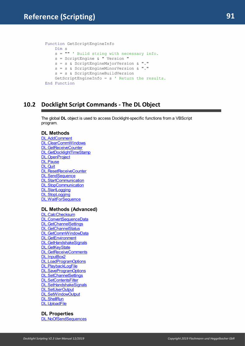
91
Docklight Scripting V2.3 User Manual 12/2019 Copyright 2019 Flachmann und Heggelbacher GbR
Reference (Scripting)
Function GetScriptEngineInfo Dim s s = "" ' Build string with necessary info. s = ScriptEngine & " Version " s = s & ScriptEngineMajorVersion & "." s = s & ScriptEngineMinorVersion & "." s = s & ScriptEngineBuildVersion GetScriptEngineInfo = s ' Return the results. End Function
10.2 Docklight Script Commands - The DL Object
The global DL object is used to access Docklight-specific functions from a VBScriptprogram.
DL MethodsDL.AddCommentDL.ClearCommWindowsDL.GetReceiveCounterDL.GetDocklightTimeStampDL.OpenProjectDL.PauseDL.QuitDL.ResetReceiveCounterDL.SendSequenceDL.StartCommunicationDL.StopCommunicationDL.StartLoggingDL.StopLoggingDL.WaitForSequence
DL Methods (Advanced)DL.CalcChecksumDL.ConvertSequenceDataDL.GetChannelSettingsDL.GetChannelStatusDL.GetCommWindowDataDL.GetEnvironmentDL.GetHandshakeSignalsDL.GetKeyStateDL.GetReceiveCommentsDL.InputBox2DL.LoadProgramOptionsDL.PlaybackLogFileDL.SaveProgramOptionsDL.SetChannelSettingsDL.SetContentsFilterDL.SetHandshakeSignalsDL.SetUserOutputDL.SetWindowOutputDL.ShellRunDL.UploadFile
DL PropertiesDL.NoOfSendSequences

92
Docklight Scripting V2.3 User Manual 12/2019 Copyright 2019 Flachmann und Heggelbacher GbR
Reference (Scripting)
DL.NoOfReceiveSequences
Additional Docklight Scripting FeaturesOnSend / OnReceive Event ProceduresFileInput / FileOutput Objects for Reading and Writing FilesSide Channels - Using Multiple Data Connections
10.2.1 Methods
10.2.1.1 AddComment
Adds a user-defined text to the communication data window and log file.
Return Value
Void
Syntax
DL.AddComment [comment] [, timeStampAfterComment] [, lineBreakAndPadding]
The AddComment method syntax has these parts:
Part Description
comment Optional. String containing the comment to add to thecommunication window(s) or log file(s).If comment is left out, AddComment will produce a line breakonly.
timeStampAfterComment
Optional Boolean value.False (Default) = No additional time stamp.True = Add a time stamp after the comment. The time stamp isadded when processing the next serial data character, notimmediately after printing the comment. This is similar to howthe "Additional time stamp..." option in the Receive Sequencedialog works.
lineBreakAndPadding Optional Boolean value.True (Default) = Additional space characters are added beforeand after the text, to separate it from the communication data.A line break is added after the comment.False = No additional spaces or line break. This is especiallyuseful in combination with the Communication Filter option,when you want to create the actual screen output entirely withthe AddComment method.
Remarks
AddComment supports the Receive Sequence comment macros %_S (bell, "beepsignal") , %_L (line break) and %_T (Timestamp) for convenience. See commentmacros for details.
You cannot use ASCII control characters like decimal code 08 (Backspace) to emulateterminal functions / display formatting. The only exception is decimal code 07 (Bell),which can be use to produce a 'beep signal', depending on your Windows soundscheme.
Example
' Example AddComment

93
Docklight Scripting V2.3 User Manual 12/2019 Copyright 2019 Flachmann und Heggelbacher GbR
Reference (Scripting)
DL.ClearCommWindowsDL.AddComment "Hello World!"' Additional line breakDL.AddComment' Use the '&' operator to concatenate strings and othervariablesr1 = 10r2 = 20DL.AddComment "Result 1 = " & r1 & " Result 2 = " & r2' The VBScript constant vbCrLf can be used for an ' additional line break, too DL.AddCommentDL.AddComment "Result 1 = " & r1 & vbCrLfDL.AddComment "Result 2 = " & r2
' Disabling the line break and padding characters gives you' better control over the actual output DL.AddComment vbCrLf + "Here's some bit of info", False, FalseDL.AddComment "rmation. " + vbCrLf, False, False
' A "beep" signal for user notificationDL.AddComment Chr(7)
10.2.1.2 ClearCommWindows
Deletes the contents of the communications window. This applies to all fourrepresentations (ASCII, HEX, Decimal, Binary) of the communication window.
Return Value
Void
Syntax
DL.ClearCommWindows
Example
' Example ClearCommWindows
' fresh startDL.ClearCommWindowsDL.AddComment "Test run started!"
10.2.1.3 GetReceiveCounter
Returns the current hit counter value for the specified Receive Sequence. The counteris incremented each time the Receive Sequence is detected within the incoming datastream. It can be reset using the ResetReceiveCounter command. The OpenProject andStartCommunication commands also reset the hit counter to zero.
Return Value
Long
Syntax
result = DL.GetReceiveCounter( nameOrIndex )

94
Docklight Scripting V2.3 User Manual 12/2019 Copyright 2019 Flachmann und Heggelbacher GbR
Reference (Scripting)
The GetReceiveCounter method syntax has these parts:
Part Description
nameOrIndex Required. String containing the Name or Sequence Index of aReceive Sequence.
Remarks
See also WaitForSequence
Example
See WaitForSequence
10.2.1.4 GetDocklightTimeStamp
Returns the current Docklight date/time stamp, according to the following settings:
1. The Docklight date/time stamp format chosen in the Options dialog:· Time stamp· Date stamp· Use time stamps with 1/100 seconds precision
2. The Windows setting for Region and Language > Formats > Short date and Longtime
The GetDocklightTimeStamp function is especially useful for printing additional timeinformation using the AddComment method.
Return Value
String
Syntax 1
result = DL.GetDocklightTimeStamp()
Remarks (Syntax 1)
GetDocklightTimeStamp adds a trailing space to the date/time string. This is forhistorical reasons and compatibility. See Syntax 2 for a trimmed version. See also theAddComment method.
Example 1
' Example GetDocklightTimeStamp
DL.ClearCommWindowsDL.StartCommunicationDL.AddComment "Communication started at " &DL.GetDocklightTimeStamp()DL.AddComment "Waiting for data..."
' Endless loop to prevent the script from terminatingimmediatelyDo DL.Pause 1 ' (the pause reduces CPU load while idle)Loop

95
Docklight Scripting V2.3 User Manual 12/2019 Copyright 2019 Flachmann und Heggelbacher GbR
Reference (Scripting)
Syntax 2
result = DL.GetDocklightTimeStamp( [ myDateTime ] [, milliseconds ] [, trimmed ])
Part Description
myDateTime Optional. a VBScript Date (Time) variable which provides the date/timeinformation in resolution "1 second". 0 (default) = Use Docklight's own time base.
milliseconds Optional integer value with corresponding milliseconds from 0..999. -1 (default) = Use Docklight's own time base.-2 = Do NOT add the milliseconds part.
trimmed Optional. True = Remove the trailing space (see Syntax 1). False (Default) = use the original format for compatibility.
Remarks (Syntax 2)
The extended syntax is typically used for formatting Receive Sequence timinginformation obtained within a Sub DL_OnReceive() event procedure. See the Example2.
The argument milliseconds = -2 is useful when creating an export file for software likeExcel that expects a standard Windows time format without milliseconds.
10.2.1.5 OpenProject
Opens an existing Docklight project file (.ptp file).
Return Value
Void
Syntax
DL.OpenProject filePathName
The OpenProject method syntax has these parts:
Part Description
filePathName Required. String containing the file path (directory and file name) ofthe Docklight project file (.ptp file) to open. The file extension .ptp canbe omitted. If no directory is specified, Docklight uses the currentworking directory.
Remarks
If filePathName is not a valid Docklight project file or does not exist, Docklight reportsan error and the script execution is stopped.
If filePathName is an empty string, a file dialog will be displayed to choose a projectfile.
All Receive Sequence counters are reset when (re)opening a Docklight project, see theResetReceiveCounter function.
Example
' Example OpenProject
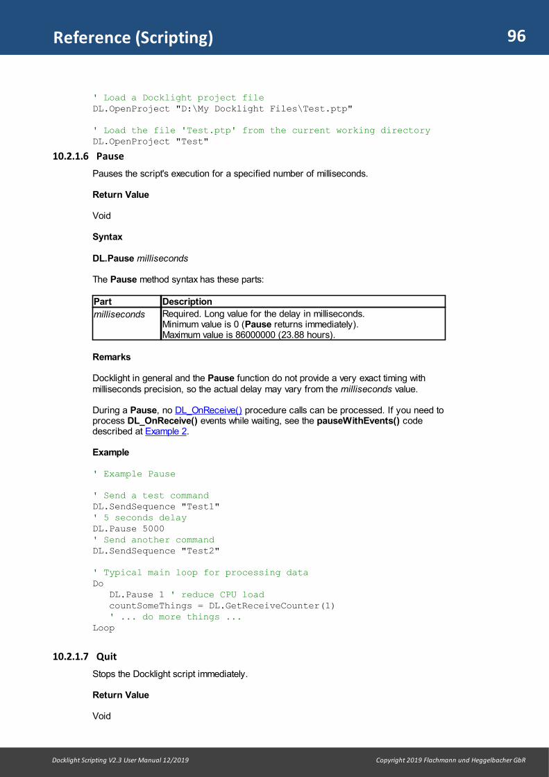
96
Docklight Scripting V2.3 User Manual 12/2019 Copyright 2019 Flachmann und Heggelbacher GbR
Reference (Scripting)
' Load a Docklight project fileDL.OpenProject "D:\My Docklight Files\Test.ptp"
' Load the file 'Test.ptp' from the current working directoryDL.OpenProject "Test"
10.2.1.6 Pause
Pauses the script's execution for a specified number of milliseconds.
Return Value
Void
Syntax
DL.Pause milliseconds
The Pause method syntax has these parts:
Part Description
milliseconds Required. Long value for the delay in milliseconds. Minimum value is 0 (Pause returns immediately). Maximum value is 86000000 (23.88 hours).
Remarks
Docklight in general and the Pause function do not provide a very exact timing withmilliseconds precision, so the actual delay may vary from the milliseconds value.
During a Pause, no DL_OnReceive() procedure calls can be processed. If you need toprocess DL_OnReceive() events while waiting, see the pauseWithEvents() codedescribed at Example 2.
Example
' Example Pause
' Send a test command DL.SendSequence "Test1"' 5 seconds delayDL.Pause 5000' Send another commandDL.SendSequence "Test2"
' Typical main loop for processing dataDo DL.Pause 1 ' reduce CPU load countSomeThings = DL.GetReceiveCounter(1) ' ... do more things ...Loop
10.2.1.7 Quit
Stops the Docklight script immediately.
Return Value
Void
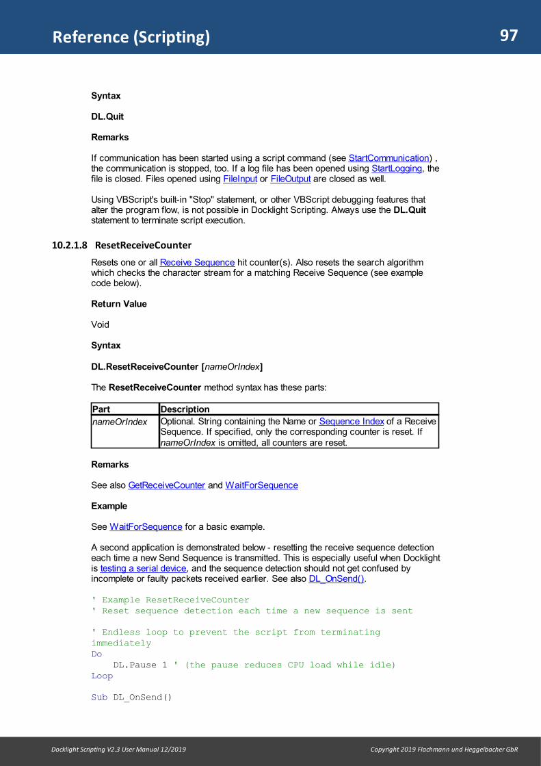
97
Docklight Scripting V2.3 User Manual 12/2019 Copyright 2019 Flachmann und Heggelbacher GbR
Reference (Scripting)
Syntax
DL.Quit
Remarks
If communication has been started using a script command (see StartCommunication) ,the communication is stopped, too. If a log file has been opened using StartLogging, thefile is closed. Files opened using FileInput or FileOutput are closed as well.
Using VBScript's built-in "Stop" statement, or other VBScript debugging features thatalter the program flow, is not possible in Docklight Scripting. Always use the DL.Quitstatement to terminate script execution.
10.2.1.8 ResetReceiveCounter
Resets one or all Receive Sequence hit counter(s). Also resets the search algorithmwhich checks the character stream for a matching Receive Sequence (see examplecode below).
Return Value
Void
Syntax
DL.ResetReceiveCounter [nameOrIndex]
The ResetReceiveCounter method syntax has these parts:
Part Description
nameOrIndex Optional. String containing the Name or Sequence Index of a ReceiveSequence. If specified, only the corresponding counter is reset. IfnameOrIndex is omitted, all counters are reset.
Remarks
See also GetReceiveCounter and WaitForSequence
Example
See WaitForSequence for a basic example.
A second application is demonstrated below - resetting the receive sequence detectioneach time a new Send Sequence is transmitted. This is especially useful when Docklightis testing a serial device, and the sequence detection should not get confused byincomplete or faulty packets received earlier. See also DL_OnSend().
' Example ResetReceiveCounter' Reset sequence detection each time a new sequence is sent
' Endless loop to prevent the script from terminatingimmediatelyDo DL.Pause 1 ' (the pause reduces CPU load while idle)Loop
Sub DL_OnSend()

98
Docklight Scripting V2.3 User Manual 12/2019 Copyright 2019 Flachmann und Heggelbacher GbR
Reference (Scripting)
DL.ResetReceiveCounterEnd Sub
10.2.1.9 SendSequence
Sends a Send Sequence or a custom data sequence. Starts the communication, if notalready running (see StartCommunication).
Return Value
Void
Syntax 1
DL.SendSequence nameOrIndex [, parameters] [, representation]
Sends out the Send Sequence that matches nameOrIndex. The SendSequencemethod syntax 1 has these parts:
Part Description
nameOrIndex Required. String containing the Name of the Send Sequence. The firstSend Sequence from the list with a name that matches nameOrIndexis used. As an alternative, you may pass an integer value specifyingthe Sequence Index. Valid Sequence Index range is from 0 to(NoOfSendSequences - 1).
parameters Optional. String containing one or several parameter value(s) for aSend Sequence with wildcards. Parameters are passed in ASCII representation by default. The spacecharacter is used to separate several different parameters fordifferent wildcard areas.
To pass parameters in HEX, Decimal or Binary representation, usethe optional representation argument described below. In HEX,Decimal or Binary representation, the comma (",") is used as aseparator between several different parameters.
representation Optional. String value to define the format for parameters list "A" =ASCII (default), "H" = Hex, "D" = Decimal or "B" = Binary.
Remarks (Syntax 1)
If the wrong number of parameters is provided by the parameters argument, or theparameter length does not match the corresponding wildcards region, Docklight will notraise an error, but apply the following rules:· If too few parameters are provided, or the parameter string is too short, all remaining
wildcards are filled up with a blank character. If you are using representation ="A" (ASCII) , the wildcards are filled with space characters (ASCII code 32). For allother formats, the wildcards will be filled with ASCII code 0.
· If too many parameters are provided, or the parameter string is too long, theparameter(s) will be truncated or ignored.
Syntax 2
DL.SendSequence "", customSequence [, representation ]
Sends out a custom data sequence. The SendSequence method syntax 2 has theseparts:

99
Docklight Scripting V2.3 User Manual 12/2019 Copyright 2019 Flachmann und Heggelbacher GbR
Reference (Scripting)
Part Description
customSequence
Required. String containing the sequence to send. The sequence ispassed in ASCII representation by default. For HEX, Decimal orBinary sequence data, use the optional representation argumentdescribed below.
representation Optional. String value to define the format for customSequence. "A"= ASCII (default), "H" = HEX, "D" = Decimal or "B" = Binary.
Example
' Example SendSequence
' Predefined Send Sequences' (0) Test: Test' (1) One: One<#><#><#><CR><LF>' (2) Two: One<?><?><?>Two<#><#><#>
DL.StartCommunicationDL.ClearCommWindows ' Send sequence without parameterDL.SendSequence "Test"' Send sequence with one parameterDL.SendSequence "One", "100"' Send sequence with two parametersDL.SendSequence "Two", "100 20"' Pass two parameters in HEX representation, including spacesand control charactersDL.SendSequence "Two", "20 31 20, 30 0D 0A", "H"' Send custom sequence data, not using a predefined SendSequenceDL.SendSequence "", "Custom Data"
' And now using a loop and the loop variable' for the Send Sequence parameter valuesFor i = 1 To 10
parString = i & " " & i+1 ' use a space to separateparameters
DL.SendSequence "Two", parStringNext
DL.StopCommunication
After running the script, the Docklight communication window could look like this:
08/05/2008 13:50:35.622 [TX] - Test08/05/2008 13:50:35.631 [TX] - One100<CR><LF>
08/05/2008 13:50:35.665 [TX] - One100Two2008/05/2008 13:50:35.682 [TX] - One 1 Two0<CR><LF>
08/05/2008 13:50:35.699 [TX] - Custom Data08/05/2008 13:50:35.713 [TX] - One1 Two208/05/2008 13:50:35.745 [TX] - One2 Two308/05/2008 13:50:35.771 [TX] - One3 Two408/05/2008 13:50:35.807 [TX] - One4 Two508/05/2008 13:50:35.846 [TX] - One5 Two608/05/2008 13:50:35.878 [TX] - One6 Two7
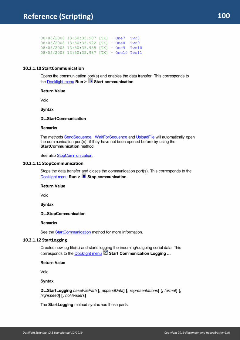
100
Docklight Scripting V2.3 User Manual 12/2019 Copyright 2019 Flachmann und Heggelbacher GbR
Reference (Scripting)
08/05/2008 13:50:35.907 [TX] - One7 Two808/05/2008 13:50:35.922 [TX] - One8 Two908/05/2008 13:50:35.955 [TX] - One9 Two1008/05/2008 13:50:35.987 [TX] - One10 Two11
10.2.1.10 StartCommunication
Opens the communication port(s) and enables the data transfer. This corresponds to
the Docklight menu Run > Start communication
Return Value
Void
Syntax
DL.StartCommunication
Remarks
The methods SendSequence, WaitForSequence and UploadFile will automatically openthe communication port(s), if they have not been opened before by using theStartCommunication method.
See also StopCommunication.
10.2.1.11 StopCommunication
Stops the data transfer and closes the communication port(s). This corresponds to the
Docklight menu Run > Stop communication.
Return Value
Void
Syntax
DL.StopCommunication
Remarks
See the StartCommunication method for more information.
10.2.1.12 StartLogging
Creates new log file(s) and starts logging the incoming/outgoing serial data. This
corresponds to the Docklight menu Start Communication Logging ...
Return Value
Void
Syntax
DL.StartLogging baseFilePath [, appendData] [, representations] [, format] [,highspeed] [, noHeaders]
The StartLogging method syntax has these parts:

101
Docklight Scripting V2.3 User Manual 12/2019 Copyright 2019 Flachmann und Heggelbacher GbR
Reference (Scripting)
Part Description
baseFilePath Required. String containing the directory and base file name for thelog file(s).
appendData Optional Boolean value.True (Default) = Append the new data to existing log file(s).False = Overwrite existing log file(s). Previously saved logging data willbe lost.
representations Optional String to choose the log file representations."A" (ASCII), "H" (HEX), "D" (Decimal) and/or "B" (Binary). Default value is "AHDB" (create all four representations ASCII, HEX, Decimal, Binary).
format Optional Integer value.0 (Default) = create plain text files (.txt)1 = create HTML files for web browsers (.htm)2 = create RTF Rich Text Format files (.rtf)
NOTE: For compatibility to V2.2. and earlier, it is also possible to use: False = plain text (.txt) True = HTML (.htm)
highspeed Optional Boolean value.False (Default) = not usedTrue = Disable communication window while logging(e.g. for monitoring high-speed communications on a slow PC).
noHeaders Optional Boolean value.False (Default) = create a standard header "Docklight Log Filestarted..." after opening the file. Create a footer "Docklight Log Filestopped" when closing the file.True = Do not create any additional header or footer information.
Remarks
See also logging and analyzing a test and the Create Log Files(s) Dialog for moreinformation on the StartLogging functionality and arguments described above.
If baseFilePath is an empty string, a file dialog will be displayed to choose the log filepath and base file name.
If StartLogging is called while another log file is still open from a previousStartLogging call, the file is closed and the new file is created / opened. This allowschanging the log file name without losing any data.
The noHeaders flag is particularly useful when you are creating log data without timestamps. You can then easily compare the result to previous test runs using an filecompare tool.
Example
' Example StartLogging
DL.ClearCommWindows DL.StartLogging "C:\DocklightLogging"' - opens four log files:' 'C:\DocklightLogging_asc.txt'' 'C:\DocklightLogging_hex.txt'' 'C:\DocklightLogging_dec.txt'' 'C:\DocklightLogging_bin.txt'' Wait for 5 secondsDL.Pause 5000
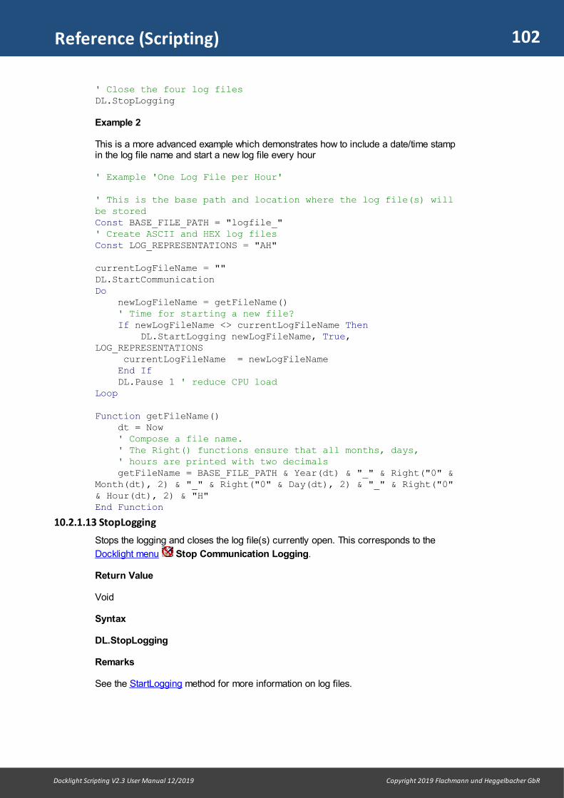
102
Docklight Scripting V2.3 User Manual 12/2019 Copyright 2019 Flachmann und Heggelbacher GbR
Reference (Scripting)
' Close the four log filesDL.StopLogging
Example 2
This is a more advanced example which demonstrates how to include a date/time stampin the log file name and start a new log file every hour
' Example 'One Log File per Hour'
' This is the base path and location where the log file(s) willbe storedConst BASE_FILE_PATH = "logfile_"' Create ASCII and HEX log filesConst LOG_REPRESENTATIONS = "AH"
currentLogFileName = ""DL.StartCommunicationDo newLogFileName = getFileName() ' Time for starting a new file? If newLogFileName <> currentLogFileName Then DL.StartLogging newLogFileName, True,LOG_REPRESENTATIONS currentLogFileName = newLogFileName End If DL.Pause 1 ' reduce CPU loadLoop
Function getFileName() dt = Now ' Compose a file name. ' The Right() functions ensure that all months, days, ' hours are printed with two decimals getFileName = BASE_FILE_PATH & Year(dt) & "_" & Right("0" &Month(dt), 2) & "_" & Right("0" & Day(dt), 2) & "_" & Right("0"& Hour(dt), 2) & "H"End Function
10.2.1.13 StopLogging
Stops the logging and closes the log file(s) currently open. This corresponds to the
Docklight menu Stop Communication Logging.
Return Value
Void
Syntax
DL.StopLogging
Remarks
See the StartLogging method for more information on log files.
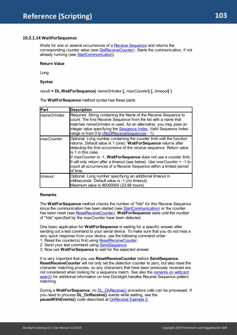
103
Docklight Scripting V2.3 User Manual 12/2019 Copyright 2019 Flachmann und Heggelbacher GbR
Reference (Scripting)
10.2.1.14 WaitForSequence
Waits for one or several occurrences of a Receive Sequence and returns thecorresponding counter value (see GetReceiveCounter). Starts the communication, if notalready running (see StartCommunication).
Return Value
Long
Syntax
result = DL.WaitForSequence( nameOrIndex [, maxCounter] [, timeout] )
The WaitForSequence method syntax has these parts:
Part Description
nameOrIndex Required. String containing the Name of the Receive Sequence tocount. The first Receive Sequence from the list with a name thatmatches nameOrIndex is used. As an alternative, you may pass aninteger value specifying the Sequence Index. Valid Sequence Indexrange is from 0 to (NoOfReceiveSequences - 1).
maxCounter Optional. Long number containing the counter limit until the functionreturns. Default value is 1 (one): WaitForSequence returns afterdetecting the first occurrence of the receive sequence. Return valueis 1 in this case. If maxCounter is -1, WaitForSequence does not use a counter limit.It will only return after a timeout (see below). Use maxCounter = -1 tocount all occurrences of a Receive Sequence within a limited periodof time.
timeout Optional. Long number specifying an additional timeout inmilliseconds. Default value is -1 (no timeout).Maximum value is 86000000 (23.88 hours).
Remarks
The WaitForSequence method checks the number of "hits" for this Receive Sequencesince the communication has been started (see StartCommunication) or the counterhas been reset (see ResetReceiveCounter). WaitForSequence waits until the numberof "hits" specified by the maxCounter have been detected.
One basic application for WaitForSequence is waiting for a specific answer aftersending out a test command to your serial device. To make sure that you do not miss avery quick response from your device, use the following command order: 1. Reset the counter(s) first using ResetReceiveCounter.2. Send your test command using SendSequence3. Now use WaitForSequence to wait for the expected answer
It is very important that you use ResetReceiveCounter before SendSequence.ResetReceiveCounter will not only set the detection counter to zero, but also reset thecharacter matching process, so any characters that have been previously received arenot considered when looking for a sequence match. See also the remarks on wildcardsearch for additional information on how Docklight handles Receive Sequence patternmatching.
During a WaitForSequence, no DL_OnReceive() procedure calls can be processed. Ifyou need to process DL_OnReceive() events while waiting, see thepauseWithEvents() code described at OnReceive Example 2.
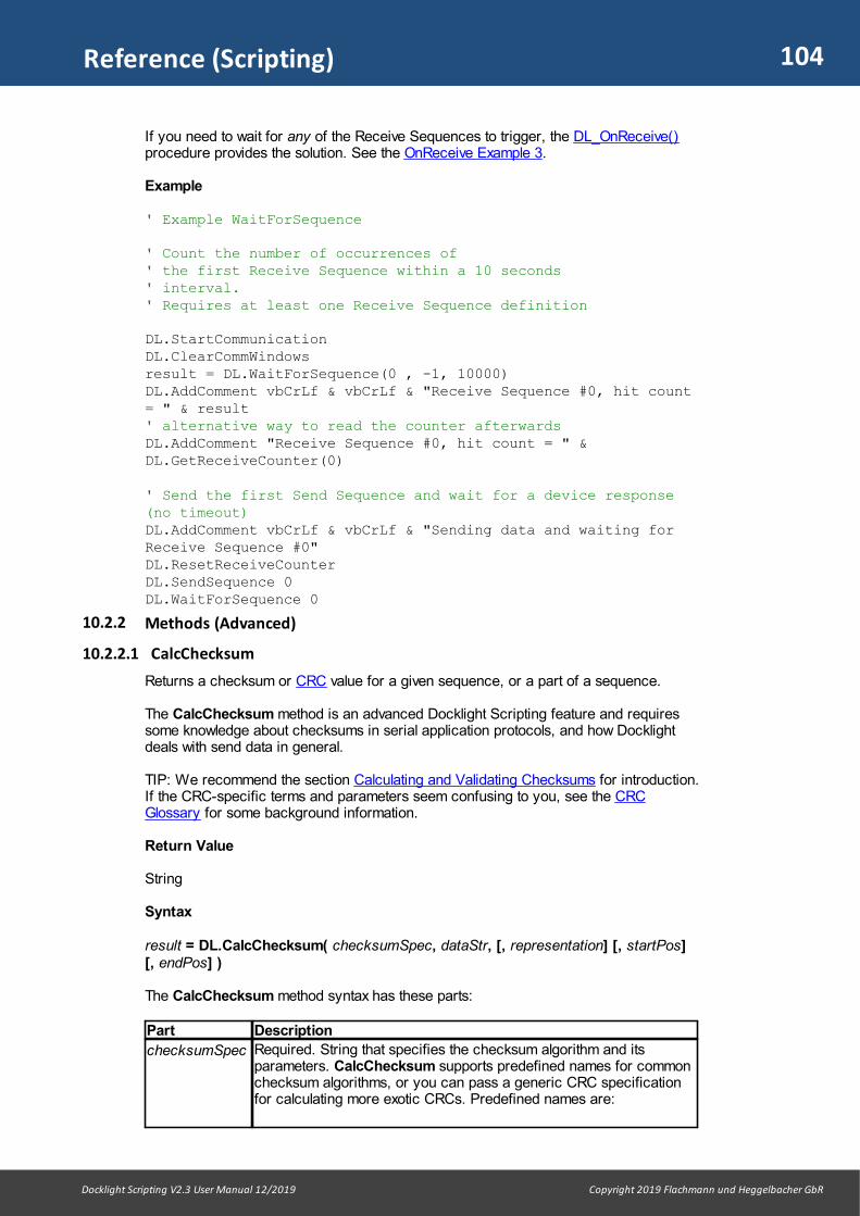
104
Docklight Scripting V2.3 User Manual 12/2019 Copyright 2019 Flachmann und Heggelbacher GbR
Reference (Scripting)
If you need to wait for any of the Receive Sequences to trigger, the DL_OnReceive()procedure provides the solution. See the OnReceive Example 3.
Example
' Example WaitForSequence
' Count the number of occurrences of' the first Receive Sequence within a 10 seconds' interval.' Requires at least one Receive Sequence definition
DL.StartCommunicationDL.ClearCommWindowsresult = DL.WaitForSequence(0 , -1, 10000)DL.AddComment vbCrLf & vbCrLf & "Receive Sequence #0, hit count= " & result' alternative way to read the counter afterwardsDL.AddComment "Receive Sequence #0, hit count = " &DL.GetReceiveCounter(0)
' Send the first Send Sequence and wait for a device response(no timeout)DL.AddComment vbCrLf & vbCrLf & "Sending data and waiting forReceive Sequence #0" DL.ResetReceiveCounterDL.SendSequence 0DL.WaitForSequence 0
10.2.2 Methods (Advanced)
10.2.2.1 CalcChecksum
Returns a checksum or CRC value for a given sequence, or a part of a sequence.
The CalcChecksum method is an advanced Docklight Scripting feature and requiressome knowledge about checksums in serial application protocols, and how Docklightdeals with send data in general.
TIP: We recommend the section Calculating and Validating Checksums for introduction.If the CRC-specific terms and parameters seem confusing to you, see the CRCGlossary for some background information.
Return Value
String
Syntax
result = DL.CalcChecksum( checksumSpec, dataStr, [, representation] [, startPos][, endPos] )
The CalcChecksum method syntax has these parts:
Part Description
checksumSpec Required. String that specifies the checksum algorithm and itsparameters. CalcChecksum supports predefined names for commonchecksum algorithms, or you can pass a generic CRC specificationfor calculating more exotic CRCs. Predefined names are:

105
Docklight Scripting V2.3 User Manual 12/2019 Copyright 2019 Flachmann und Heggelbacher GbR
Reference (Scripting)
"MOD256", "XOR", "CRC-8", "CRC-CCITT", "CRC-16", "CRC-MODBUS" and "CRC-32"See checksumSpec Format for the full format specification.
dataStr Required. String value that contains the input Sequence for thechecksum calculation, as for example returned by theOnSend_GetData() function.
representation Optional. String value to define the format of the dataStr Sequence:"H" = Hex (default), "A" = ASCII , "D" = Decimal or "B" = Binary.
startPos Optional Integer value. Specifies the character position where thecalculation should start. Default value is 1 (beginning of the dataStrSequence).
startPos also accepts negative values, e.g. -1 for "last character", -2for "2nd character from the end", -3 for "3rd character from the end".
endPos Optional Integer value. Specifies the last character that should beincluded in the calculation. Default value is the size of the dataStrSequence.
endPos also accepts negative values, see startPos above.
Remarks
The return value is a string with the CRC/checksum in the Docklight HEX sequenceformat, e.g. "CB F4 39 26". The number of HEX bytes returned depends on the width ofthe checksum algorithm. See the example script and communications window outputbelow.
With the help of CalcChecksum you can generate specific checksums for SendSequences on the fly, or use advanced checksum validations for received data. See theSub DL_OnSend() Event Procedure for details.
Standard checksums can already be processed without script code using theChecksum part of the Edit Send Sequence / Edit Receive Sequence dialogs. See alsothe related Modbus protocol example example.
Example
' Example CalcChecksum
DL.ClearCommWindows
DL.AddCommentDL.AddComment "Simple checksum (Mod 256) for '123456789'"DL.AddComment "CalcChecksum = " & DL.CalcChecksum("MOD256","123456789", "A")
DL.AddCommentDL.AddComment "8 bit CRC (CRC DOW) for '123456789'"DL.AddComment "CalcChecksum = " & DL.CalcChecksum("CRC-DOW","123456789", "A")
DL.AddCommentDL.AddComment "16 bit CRC (CRC-16) for '123456789'"DL.AddComment "CalcChecksum = " & DL.CalcChecksum("CRC-16","123456789", "A")
DL.AddComment
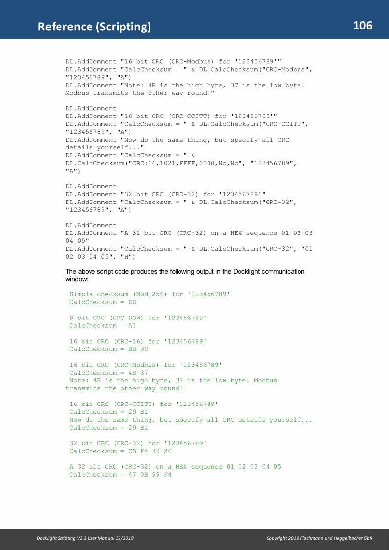
106
Docklight Scripting V2.3 User Manual 12/2019 Copyright 2019 Flachmann und Heggelbacher GbR
Reference (Scripting)
DL.AddComment "16 bit CRC (CRC-Modbus) for '123456789'"DL.AddComment "CalcChecksum = " & DL.CalcChecksum("CRC-Modbus","123456789", "A")DL.AddComment "Note: 4B is the high byte, 37 is the low byte.Modbus transmits the other way round!"
DL.AddCommentDL.AddComment "16 bit CRC (CRC-CCITT) for '123456789'"DL.AddComment "CalcChecksum = " & DL.CalcChecksum("CRC-CCITT","123456789", "A")DL.AddComment "Now do the same thing, but specify all CRCdetails yourself..."DL.AddComment "CalcChecksum = " &DL.CalcChecksum("CRC:16,1021,FFFF,0000,No,No", "123456789","A")
DL.AddCommentDL.AddComment "32 bit CRC (CRC-32) for '123456789'"DL.AddComment "CalcChecksum = " & DL.CalcChecksum("CRC-32","123456789", "A")
DL.AddComment DL.AddComment "A 32 bit CRC (CRC-32) on a HEX sequence 01 02 0304 05"DL.AddComment "CalcChecksum = " & DL.CalcChecksum("CRC-32", "0102 03 04 05", "H")
The above script code produces the following output in the Docklight communicationwindow:
Simple checksum (Mod 256) for '123456789' CalcChecksum = DD 8 bit CRC (CRC DOW) for '123456789' CalcChecksum = A1 16 bit CRC (CRC-16) for '123456789' CalcChecksum = BB 3D 16 bit CRC (CRC-Modbus) for '123456789' CalcChecksum = 4B 37 Note: 4B is the high byte, 37 is the low byte. Modbustransmits the other way round! 16 bit CRC (CRC-CCITT) for '123456789' CalcChecksum = 29 B1 Now do the same thing, but specify all CRC details yourself... CalcChecksum = 29 B1 32 bit CRC (CRC-32) for '123456789' CalcChecksum = CB F4 39 26 A 32 bit CRC (CRC-32) on a HEX sequence 01 02 03 04 05 CalcChecksum = 47 0B 99 F4

107
Docklight Scripting V2.3 User Manual 12/2019 Copyright 2019 Flachmann und Heggelbacher GbR
Reference (Scripting)
10.2.2.2 ConvertSequenceData
Converts Sequence data to/from a float number, an integer number, or other commontypes of data in technical applications.
Return Value
String
Syntax
result = DL.ConvertSequenceData( conversionType, source, [, representation] [,bigEndian ] )
The ConvertSequenceData method syntax has these parts:
Part Description
conversionType Required. String that specifies the conversion type and direction. See below for the list of conversions and examples.
source Required. Input data string for the conversion. This can be a DocklightSequence, e.g. "4B 06 9E 3F", or a string with the application value,e.g. "1.234567". See below for details.
representation Optional. Format of the sequence string (either source or result,depending on conversionType):"H" = Hex (default), "D" = Decimal or "B" = Binary.
bigEndian Optional. Boolean value to define the byte order for integer or floatconversions. True (default): Use big-endian byte order (first character is mostsignificant)False: use little-endian byte order (first character is least significant)
The conversionType argument supports the following values and types of conversions:
Value Description
"toSingle" Convert source to a single precision float number. source: IEEE single precision (32 bit) sequenceresult: string with floating point number in non-localized format, usesperiod (".") as the decimal separator.Example:DL.ConvertSequenceData("toSingle", "3F 9E 06 4B") returns: 1.234567
"fromSingle" Convert source to a IEEE single precision (32 bit) sequencesource: string with floating point number. Both period (".") and comma(",") are accepted as decimal separator.result: 32 bit sequence dataExample:DL.ConvertSequenceData("fromSingle", "1.234567") returns: 3F 9E 06 4B
"toDouble" Convert source to a double precision float number. source: IEEE double precision (64 bit) sequenceresult: string with floating point number in non-localized format (seeabove) Example:DL.ConvertSequenceData("toDouble", "103 154 149 160081 161 036 075", "D", False) returns: 9.87987987987E+53
"fromDouble" Convert to a IEEE double precision (64 bit) sequence

108
Docklight Scripting V2.3 User Manual 12/2019 Copyright 2019 Flachmann und Heggelbacher GbR
Reference (Scripting)
source: string with floating point number. Both period (".") and comma(",") are accepted as decimal separator.result: 64 bit sequence dataExample:DL.ConvertSequenceData("fromDouble","9.87987987987E+53", "D", False) returns: 103 154 149 160 081 161 036 075
"fromText" Converts a plain text into a Hex, Decimal or Binary sequence. E.g. DL.AddComment DL.ConvertSequenceData("fromText","Hello World") returns: 48 65 6C 6C 6F 20 57 6F 72 6C 64
bigEndian = false: If this option is used for "fromText", the resultingsequence is without separator, e.g. 48656C6C6F20576F726C64
"toInteger16""fromInteger16"
Convert to/from a signed 16 bit integer value Examples:DL.ConvertSequenceData("toInteger16", "80 00")returns: -32768DL.ConvertSequenceData("fromInteger16", "-1")returns: FF FF
"toUnsigned16""fromUnsigned16"
Same as "toInteger16" / "fromInteger16", but for unsigned 16 bitinteger dataExamples:DL.ConvertSequenceData("toUnsigned16", "80 00")returns: 32768DL.ConvertSequenceData("fromUnsigned16", "65535","D")returns: 255 255
"toInteger32""fromInteger32"
Convert to/from a signed 32 bit integer value Examples:DL.ConvertSequenceData("toInteger32", "00 00 0080", "H", False)returns: -2147483648DL.ConvertSequenceData("fromInteger32", "-2", "H",False)returns: FE FF FF FF
"toUnsigned32""fromUnsigned32"
Same as "toInteger32" / "fromInteger32", but for unsigned 32 bitinteger dataExamples:DL.ConvertSequenceData("toUnsigned32", "FF 00 FF00")returns: 4278255360DL.ConvertSequenceData("fromUnsigned32","21121977", "D")returns: 001 066 075 185
"toBool" Returns "True" if the first source character is <> 0Example:DL.ConvertSequenceData("toBool", "00")returns: FalseDL.ConvertSequenceData("toBool", "01 00")returns: True
"toText" Converts sequence data into a text string with printing characters only(see ASCII Character Set). ASCII code 0 - 31 and 127 - 255 arefiltered out and do not appear in the result.source: sequence with the original data, including non-printingcharacter codes

109
Docklight Scripting V2.3 User Manual 12/2019 Copyright 2019 Flachmann und Heggelbacher GbR
Reference (Scripting)
result: the ASCII text using only ASCII code 32 - 126 Example:DL.ConvertSequenceData("toText", "FF 48 65 6C 6C 6F21 0D 00 00")returns: Hello!
Remarks
Carefully check your protocol specification on the data format, including Endianness(little endian / big endian).
When using the result of a "toSingle" or "toDouble" conversion for further calculations,keep in mind that result can be a non-numeric strings like "NaN" (not a number) or "Inf"(Infinity).
Note that "toText" is not the same as reading out a data sequence in ASCIIrepresentation ("A"). Example:
DL.AddComment DL.OnSend_GetData("A") DL.AddComment DL.ConvertSequenceData("toText",DL.OnSend_GetData("H"))
could return the following:
Hello!<CR><NUL><NUL> Hello!
10.2.2.3 GetChannelSettings
Returns the current communication channel settings (COM port number or TCPaddress, serial port settings).
NOTE: GetChannelSettings is a companion to the SetChannelSettings method, andintended for advanced Docklight Scripting applications where control of thecommunication channel settings is required.
Return Value
String
Syntax
result = DL.GetChannelSettings( [channelNo] )
The GetChannelSettings method syntax has these parts:
Part Description
channelNo Optional. Integer that specifies the communication channel ifCommunication Mode: Monitoring is used. Default value is 1 (Channel1).
Remarks
GetChannelSettings returns a string with the current serial or TCP settings for thespecified communication channel.
If the channel is a serial port, the return value has the following format: COMxxx: BaudRate, Parity, DataBits, StopBits, FlowControl, ParityErrorChare.g. "COM1:9600,NONE,8,1,OFF,63"
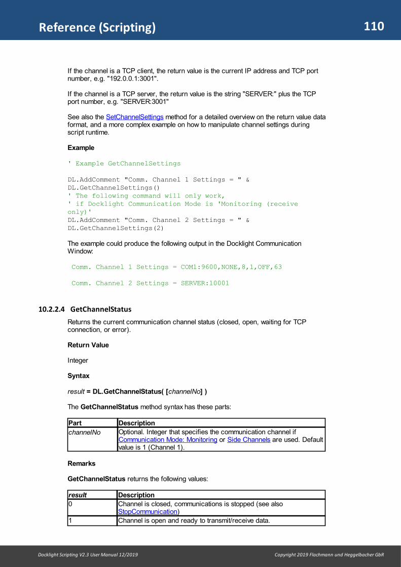
110
Docklight Scripting V2.3 User Manual 12/2019 Copyright 2019 Flachmann und Heggelbacher GbR
Reference (Scripting)
If the channel is a TCP client, the return value is the current IP address and TCP portnumber, e.g. "192.0.0.1:3001".
If the channel is a TCP server, the return value is the string "SERVER:" plus the TCPport number, e.g. "SERVER:3001"
See also the SetChannelSettings method for a detailed overview on the return value dataformat, and a more complex example on how to manipulate channel settings duringscript runtime.
Example
' Example GetChannelSettings
DL.AddComment "Comm. Channel 1 Settings = " &DL.GetChannelSettings()' The following command will only work, ' if Docklight Communication Mode is 'Monitoring (receiveonly)'DL.AddComment "Comm. Channel 2 Settings = " &DL.GetChannelSettings(2)
The example could produce the following output in the Docklight CommunicationWindow:
Comm. Channel 1 Settings = COM1:9600,NONE,8,1,OFF,63 Comm. Channel 2 Settings = SERVER:10001
10.2.2.4 GetChannelStatus
Returns the current communication channel status (closed, open, waiting for TCPconnection, or error).
Return Value
Integer
Syntax
result = DL.GetChannelStatus( [channelNo] )
The GetChannelStatus method syntax has these parts:
Part Description
channelNo Optional. Integer that specifies the communication channel ifCommunication Mode: Monitoring or Side Channels are used. Defaultvalue is 1 (Channel 1).
Remarks
GetChannelStatus returns the following values:
result Description
0 Channel is closed, communications is stopped (see alsoStopCommunication)
1 Channel is open and ready to transmit/receive data.
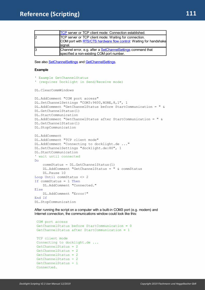
111
Docklight Scripting V2.3 User Manual 12/2019 Copyright 2019 Flachmann und Heggelbacher GbR
Reference (Scripting)
TCP server or TCP client mode: Connection established.
2 TCP server or TCP client mode: Waiting for connection.COM port with RTS/CTS hardware flow control: Waiting for handshakesignal.
3 Channel error, e.g. after a SetChannelSettings command thatspecified a non-existing COM port number.
See also SetChannelSettings and GetChannelSettings.
Example
' Example GetChannelStatus' (requires Docklight in Send/Receive mode)
DL.ClearCommWindows
DL.AddComment "COM port access"DL.SetChannelSettings "COM3:9600,NONE,8,1", 1DL.AddComment "GetChannelStatus before StartCommunication = " &DL.GetChannelStatus(1)DL.StartCommunicationDL.AddComment "GetChannelStatus after StartCommunication = " &DL.GetChannelStatus(1)DL.StopCommunication
DL.AddCommentDL.AddComment "TCP client mode"DL.AddComment "Connecting to docklight.de ..."DL.SetChannelSettings "docklight.de:80", 1DL.StartCommunication' wait until connectedDo commStatus = DL.GetChannelStatus(1) DL.AddComment "GetChannelStatus = " & commStatus DL.Pause 10Loop Until commStatus <> 2If commStatus = 1 Then DL.AddComment "Connected."Else DL.AddComment "Error!"End IfDL.StopCommunication
After running the script on a computer with a built-in COM3 port (e.g. modem) andInternet connection, the communications window could look like this:
COM port access GetChannelStatus before StartCommunication = 0 GetChannelStatus after StartCommunication = 1 TCP client mode Connecting to docklight.de ... GetChannelStatus = 2 GetChannelStatus = 2 GetChannelStatus = 2 GetChannelStatus = 2 GetChannelStatus = 1 Connected.
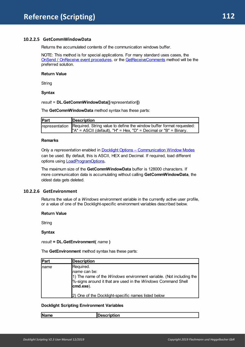
112
Docklight Scripting V2.3 User Manual 12/2019 Copyright 2019 Flachmann und Heggelbacher GbR
Reference (Scripting)
10.2.2.5 GetCommWindowData
Returns the accumulated contents of the communication windows buffer.
NOTE: This method is for special applications. For many standard uses cases, theOnSend / OnReceive event procedures, or the GetReceiveComments method will be thepreferred solution.
Return Value
String
Syntax
result = DL.GetCommWindowData([representation])
The GetCommWindowData method syntax has these parts:
Part Description
representation Required. String value to define the window buffer format requested: "A" = ASCII (default), "H" = Hex, "D" = Decimal or "B" = Binary.
Remarks
Only a representation enabled in Docklight Options – Communication Window Modes
can be used. By default, this is ASCII, HEX and Decimal. If required, load different
options using LoadProgramOptions.
The maximum size of the GetCommWindowData buffer is 128000 characters. If
more communication data is accumulating without calling GetCommWindowData, the
oldest data gets deleted.
10.2.2.6 GetEnvironment
Returns the value of a Windows environment variable in the currently active user profile,or a value of one of the Docklight-specific environment variables described below.
Return Value
String
Syntax
result = DL.GetEnvironment( name )
The GetEnvironment method syntax has these parts:
Part Description
name Required. name can be:1) The name of the Windows environment variable. (Not including the%-signs around it that are used in the Windows Command Shellcmd.exe).
2) One of the Docklight-specific names listed below
Docklight Scripting Environment Variables
Name Description

113
Docklight Scripting V2.3 User Manual 12/2019 Copyright 2019 Flachmann und Heggelbacher GbR
Reference (Scripting)
DOCKLIGHT_VERSION Docklight Scripting application version
DOCKLIGHT_SCRIPTDIR the folder the script runs in
DOCKLIGHT_DIALOGDIR the folder used for the last script file dialog used
DOCKLIGHT_PORTLIST list of COM ports available on this PC
DOCKLIGHT_SENDSEQ list of all Send Sequence names in the current Docklightproject (.ptp file)
DOCKLIGHT_RECEIVESEQ list of all Receive Sequence names
DOCKLIGHT_SENDSEQDEF list of all Send Sequences Name and Sequence in HEXformat. Name and Sequence are returned in separatedtext lines
DOCKLIGHT_SENDSEQDEF:SequenceName
Lists the definition only for the sequence names thatmatch SequenceName.
SequenceName can contain wildcards, e.g. you canuse:DOCKLIGHT_SENDSEQDEF:Test*
DOCKLIGHT_RECEIVESEQDEF
same as DOCKLIGHT_SENDSEQDEF but for ReceiveSequences
Remarks
The list of environment variables used in the example below is just an example.
For details and available variables on other versions of Windows, please refer to theother resources, e.g. the "Windows XP Command shell overview" at www.microsoft.com . For a list of variables available on your current user profile, open a WindowsCommand Processor window (cmd.exe), then type SET and press Enter.
NOTE: In Docklight Scripting V2.0 and earlier this method was calledGetEnvironmentVariable. The old name is still supported for compatibility reasons. Itwas changed to avoid confusion with the Windows API function of the same name.
Example
' Example GetEnvironment
nameList ="ALLUSERSPROFILE,APPDATA,COMPUTERNAME,HOMEDRIVE,HOMEPATH,LOCALAPPDATA,LOGONSERVER,NUMBER_OF_PROCESSORS,OS,PROCESSOR_ARCHITECTURE,PROCESSOR_IDENTIFIER,PROCESSOR_LEVEL,PROCESSOR_REVISION,PUBLIC,TEMP,TMP,USERDOMAIN,USERNAME,USERPROFILE"
DL.AddComment "Running Docklight Scripting " &DL.GetEnvironment("DOCKLIGHT_VERSION")nameArray = Split(nameList , ",")For i = 0 To UBound(nameArray) name = nameArray(i) DL.AddComment name & " = " & DL.GetEnvironment(name)Next
On a Windows 7 x64 PC, the communications window output could look like this:
Running Docklight Scripting Version 2.1.4 ALLUSERSPROFILE = C:\ProgramData APPDATA = C:\Users\docklight\AppData\Roaming COMPUTERNAME = FUHEDV5 HOMEDRIVE = C:

114
Docklight Scripting V2.3 User Manual 12/2019 Copyright 2019 Flachmann und Heggelbacher GbR
Reference (Scripting)
HOMEPATH = \Users\docklight LOCALAPPDATA = C:\Users\docklight\AppData\Local LOGONSERVER = \\FUHEDV5 NUMBER_OF_PROCESSORS = 4 OS = Windows_NT PROCESSOR_ARCHITECTURE = x86 PROCESSOR_IDENTIFIER = Intel64 Family 6 Model 37 Stepping 5,GenuineIntel PROCESSOR_LEVEL = 6 PROCESSOR_REVISION = 2505 PUBLIC = C:\Users\Public TEMP = C:\Users\docklight\AppData\Local\Temp TMP = C:\Users\docklight\AppData\Local\Temp USERDOMAIN = FUHEDV5 USERNAME = docklight USERPROFILE = C:\Users\docklight
10.2.2.7 GetHandshakeSignals
Returns the current handshake signal states (CTS, DSR, DCD, RI) as an integer bitvalue, in the same way the Receive Sequence function character ‘!’ works.
Return Value
Integer
Syntax
result = DL.GetHandshakeSignals()
Remarks
result is a bit value with the following components:
Bit No. Decimal Value Handshake Signal
0 001 CTS = High
1 002 DSR = High
2 004 DCD = High
3 008 RI (Ring Indicator) = High
In Tap Pro / Tap 485 applications, GetHandshakeSignals returns the followingextended set of handshake signal states:
Bit No. Decimal Value Handshake Signal
0 001 CTS = High (DCE side / Docklight Receive Channel 2)
1 002 DSR = High (DCE side / Channel 2)
2 004 DCD = High (DCE side / Channel 2)
3 008 RI (Ring Indicator) = High (DCE side / Channel 2)
4 016 RTS = High (DTE side / Channel 1)
5 032 DTR = High (DTE side / Channel 1)
See also SetHandshakeSignals for controlling the state of the RTS and DTR lines.
Example
' Example GetHandshakeSignalsDL.StartCommunication
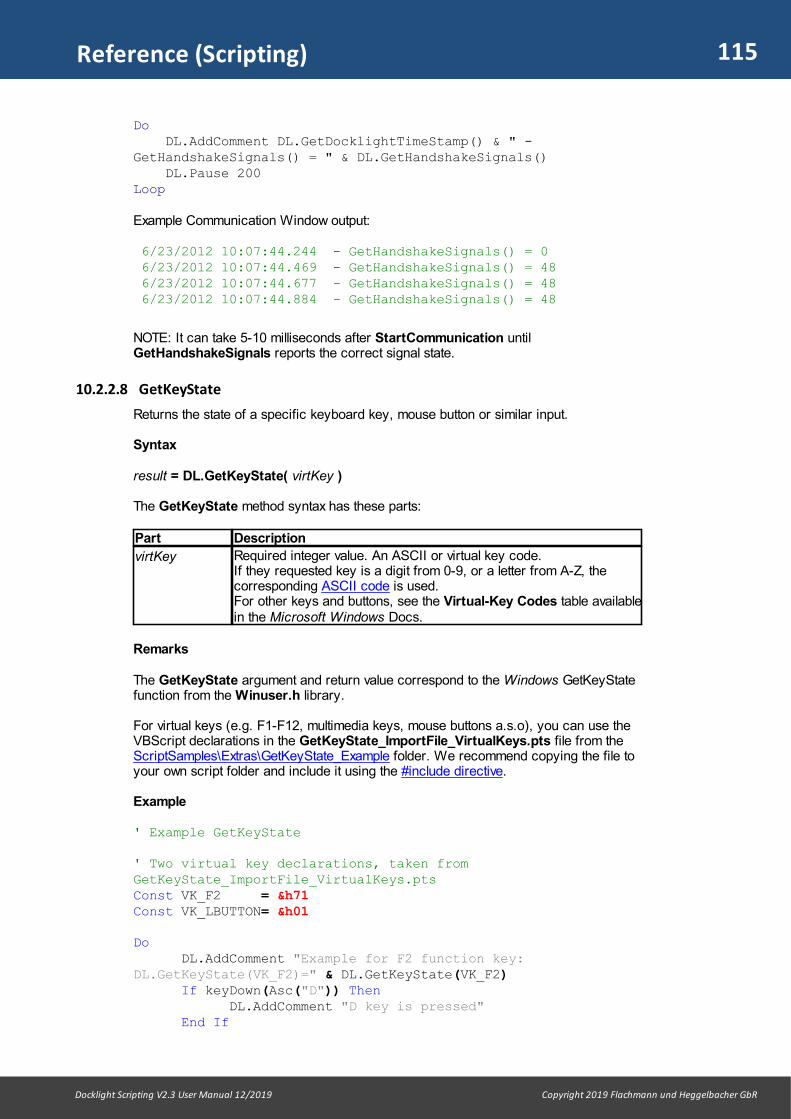
115
Docklight Scripting V2.3 User Manual 12/2019 Copyright 2019 Flachmann und Heggelbacher GbR
Reference (Scripting)
Do DL.AddComment DL.GetDocklightTimeStamp() & " -GetHandshakeSignals() = " & DL.GetHandshakeSignals() DL.Pause 200Loop
Example Communication Window output:
6/23/2012 10:07:44.244 - GetHandshakeSignals() = 0 6/23/2012 10:07:44.469 - GetHandshakeSignals() = 48 6/23/2012 10:07:44.677 - GetHandshakeSignals() = 48 6/23/2012 10:07:44.884 - GetHandshakeSignals() = 48
NOTE: It can take 5-10 milliseconds after StartCommunication untilGetHandshakeSignals reports the correct signal state.
10.2.2.8 GetKeyState
Returns the state of a specific keyboard key, mouse button or similar input.
Syntax
result = DL.GetKeyState( virtKey )
The GetKeyState method syntax has these parts:
Part Description
virtKey Required integer value. An ASCII or virtual key code. If they requested key is a digit from 0-9, or a letter from A-Z, thecorresponding ASCII code is used. For other keys and buttons, see the Virtual-Key Codes table availablein the Microsoft Windows Docs.
Remarks
The GetKeyState argument and return value correspond to the Windows GetKeyStatefunction from the Winuser.h library.
For virtual keys (e.g. F1-F12, multimedia keys, mouse buttons a.s.o), you can use theVBScript declarations in the GetKeyState_ImportFile_VirtualKeys.pts file from theScriptSamples\Extras\GetKeyState_Example folder. We recommend copying the file toyour own script folder and include it using the #include directive.
Example
' Example GetKeyState
' Two virtual key declarations, taken fromGetKeyState_ImportFile_VirtualKeys.pts Const VK_F2 = &h71Const VK_LBUTTON= &h01
Do DL.AddComment "Example for F2 function key:
DL.GetKeyState(VK_F2)=" & DL.GetKeyState(VK_F2)If keyDown(Asc("D")) Then
DL.AddComment "D key is pressed"End If
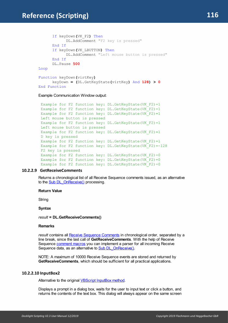
116
Docklight Scripting V2.3 User Manual 12/2019 Copyright 2019 Flachmann und Heggelbacher GbR
Reference (Scripting)
If keyDown(VK_F2) ThenDL.AddComment "F2 key is pressed"
End IfIf keyDown(VK_LBUTTON) Then
DL.AddComment "Left mouse button is pressed"End IfDL.Pause 500
Loop
Function keyDown(virtKey) keyDown = (DL.GetKeyState(virtKey) And 128) > 0
End Function
Example Communication Window output:
Example for F2 function key: DL.GetKeyState(VK_F2)=1 Example for F2 function key: DL.GetKeyState(VK_F2)=1 Example for F2 function key: DL.GetKeyState(VK_F2)=1 Left mouse button is pressed Example for F2 function key: DL.GetKeyState(VK_F2)=1 Left mouse button is pressed Example for F2 function key: DL.GetKeyState(VK_F2)=1 D key is pressed Example for F2 function key: DL.GetKeyState(VK_F2)=1 Example for F2 function key: DL.GetKeyState(VK_F2)=-128 F2 key is pressed Example for F2 function key: DL.GetKeyState(VK_F2)=0 Example for F2 function key: DL.GetKeyState(VK_F2)=0 Example for F2 function key: DL.GetKeyState(VK_F2)=0
10.2.2.9 GetReceiveComments
Returns a chronological list of all Receive Sequence comments issued, as an alternativeto the Sub DL_OnReceive() processing.
Return Value
String
Syntax
result = DL.GetReceiveComments()
Remarks
result contains all Receive Sequence Comments in chronological order, separated by aline break, since the last call of GetReceiveComments. With the help of ReceiveSequence comment macros you can implement a parser for all incoming ReceiveSequence data, as an alternative to Sub DL_OnReceive().
NOTE: A maximum of 10000 Receive Sequence events are stored and returned byGetReceiveComments, which should be sufficient for all practical applications.
10.2.2.10 InputBox2
Alternative to the original VBScript InputBox method.
Displays a prompt in a dialog box, waits for the user to input text or click a button, andreturns the contents of the text box. This dialog will always appear on the same screen
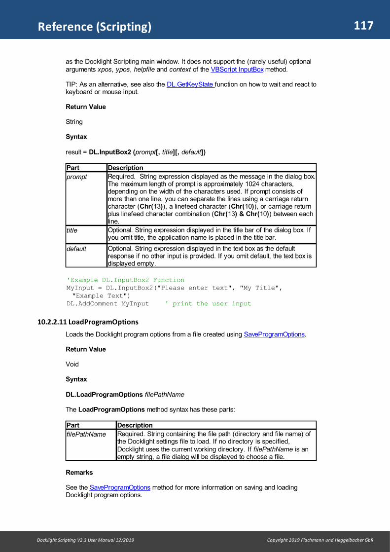
117
Docklight Scripting V2.3 User Manual 12/2019 Copyright 2019 Flachmann und Heggelbacher GbR
Reference (Scripting)
as the Docklight Scripting main window. It does not support the (rarely useful) optionalarguments xpos, ypos, helpfile and context of the VBScript InputBox method.
TIP: As an alternative, see also the DL.GetKeyState function on how to wait and react tokeyboard or mouse input.
Return Value
String
Syntax
result = DL.InputBox2 (prompt[, title][, default])
Part Description
prompt Required. String expression displayed as the message in the dialog box.The maximum length of prompt is approximately 1024 characters,depending on the width of the characters used. If prompt consists ofmore than one line, you can separate the lines using a carriage returncharacter (Chr(13)), a linefeed character (Chr(10)), or carriage returnplus linefeed character combination (Chr(13) & Chr(10)) between eachline.
title Optional. String expression displayed in the title bar of the dialog box. Ifyou omit title, the application name is placed in the title bar.
default Optional. String expression displayed in the text box as the defaultresponse if no other input is provided. If you omit default, the text box isdisplayed empty.
'Example DL.InputBox2 FunctionMyInput = DL.InputBox2("Please enter text", "My Title","Example Text")
DL.AddComment MyInput ' print the user input
10.2.2.11 LoadProgramOptions
Loads the Docklight program options from a file created using SaveProgramOptions.
Return Value
Void
Syntax
DL.LoadProgramOptions filePathName
The LoadProgramOptions method syntax has these parts:
Part Description
filePathName Required. String containing the file path (directory and file name) ofthe Docklight settings file to load. If no directory is specified,Docklight uses the current working directory. If filePathName is anempty string, a file dialog will be displayed to choose a file.
Remarks
See the SaveProgramOptions method for more information on saving and loadingDocklight program options.
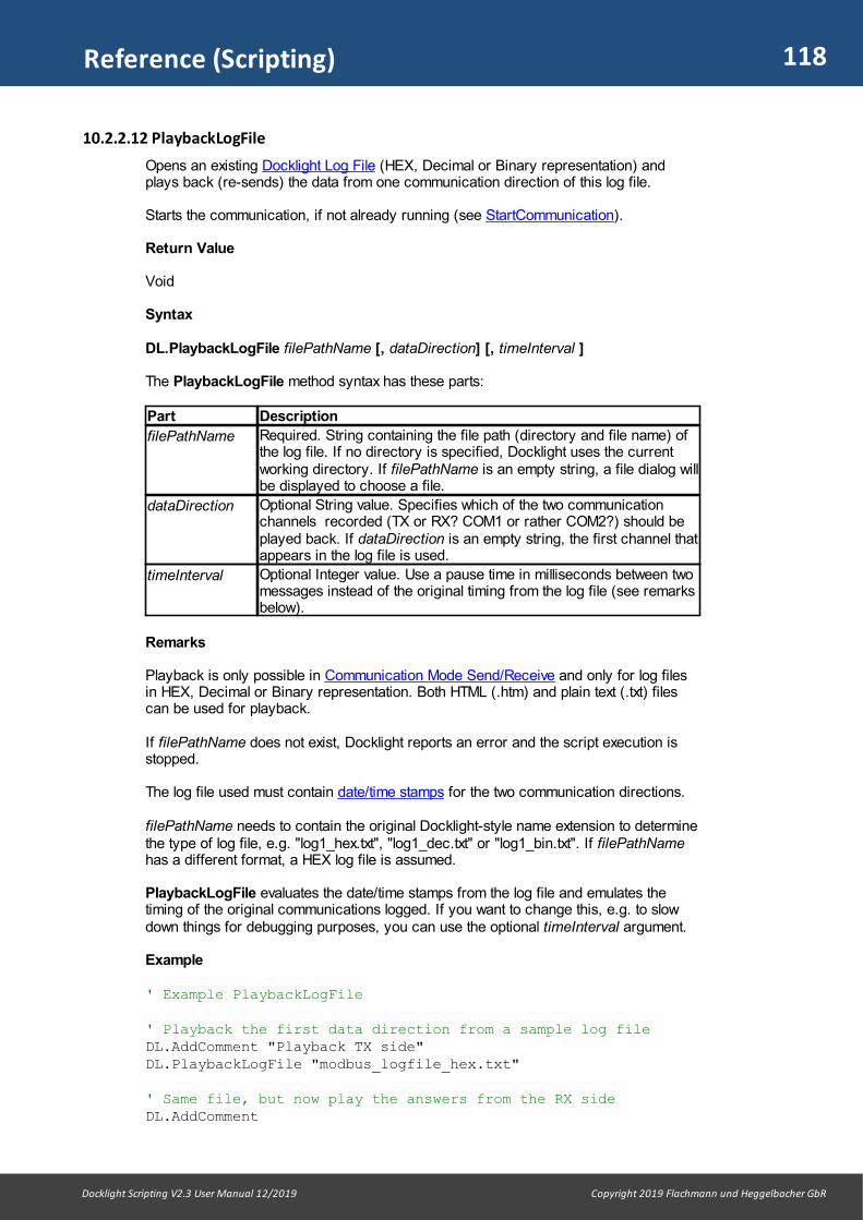
118
Docklight Scripting V2.3 User Manual 12/2019 Copyright 2019 Flachmann und Heggelbacher GbR
Reference (Scripting)
10.2.2.12 PlaybackLogFile
Opens an existing Docklight Log File (HEX, Decimal or Binary representation) andplays back (re-sends) the data from one communication direction of this log file.
Starts the communication, if not already running (see StartCommunication).
Return Value
Void
Syntax
DL.PlaybackLogFile filePathName [, dataDirection] [, timeInterval ]
The PlaybackLogFile method syntax has these parts:
Part Description
filePathName Required. String containing the file path (directory and file name) ofthe log file. If no directory is specified, Docklight uses the currentworking directory. If filePathName is an empty string, a file dialog willbe displayed to choose a file.
dataDirection Optional String value. Specifies which of the two communicationchannels recorded (TX or RX? COM1 or rather COM2?) should beplayed back. If dataDirection is an empty string, the first channel thatappears in the log file is used.
timeInterval Optional Integer value. Use a pause time in milliseconds between twomessages instead of the original timing from the log file (see remarksbelow).
Remarks
Playback is only possible in Communication Mode Send/Receive and only for log filesin HEX, Decimal or Binary representation. Both HTML (.htm) and plain text (.txt) filescan be used for playback.
If filePathName does not exist, Docklight reports an error and the script execution isstopped.
The log file used must contain date/time stamps for the two communication directions.
filePathName needs to contain the original Docklight-style name extension to determinethe type of log file, e.g. "log1_hex.txt", "log1_dec.txt" or "log1_bin.txt". If filePathNamehas a different format, a HEX log file is assumed.
PlaybackLogFile evaluates the date/time stamps from the log file and emulates thetiming of the original communications logged. If you want to change this, e.g. to slowdown things for debugging purposes, you can use the optional timeInterval argument.
Example
' Example PlaybackLogFile
' Playback the first data direction from a sample log file DL.AddComment "Playback TX side"DL.PlaybackLogFile "modbus_logfile_hex.txt"
' Same file, but now play the answers from the RX sideDL.AddComment

119
Docklight Scripting V2.3 User Manual 12/2019 Copyright 2019 Flachmann und Heggelbacher GbR
Reference (Scripting)
DL.AddCommentDL.AddComment "Playback RX side"DL.PlaybackLogFile "modbus_logfile_hex.txt", "RX"
' Same file, but use a fixed time interval between theindividual sequences.DL.AddCommentDL.AddCommentDL.AddComment "Playback TX with fixed 500 millisecondsinterval"DL.PlaybackLogFile "modbus_logfile_hex.txt", "", 500
We assume that the log file modbus_logfile_hex.txt was created during a previousModbus communication session and contains the following information: 8/29/2006 18:45:23.19 [TX] - 01 04 00 00 00 01 31 CA 8/29/2006 18:45:23.34 [RX] - 01 04 02 FF FF B8 80 8/29/2006 18:45:33.14 [TX] - 02 04 00 00 00 01 31 F9 8/29/2006 18:45:33.29 [RX] - 02 04 02 27 10 E7 0C 8/29/2006 18:45:43.23 [TX] - 03 04 00 00 00 01 30 28 8/29/2006 18:45:43.39 [RX] - 03 04 02 00 00 C0 F0 8/29/2006 18:45:58.72 [TX] - 04 04 00 00 00 01 31 9F 8/29/2006 18:45:58.87 [RX] - 04 04 02 04 00 77 F0
After running the example script, the communications window could look like this:
Playback TX side
4/26/2009 13:29:15.841 [TX] - 01 04 00 00 00 01 31 CA 4/26/2009 13:29:25.788 [TX] - 02 04 00 00 00 01 31 F9 4/26/2009 13:29:35.879 [TX] - 03 04 00 00 00 01 30 28 4/26/2009 13:29:51.367 [TX] - 04 04 00 00 00 01 31 9F Playback RX side
4/26/2009 13:29:51.545 [TX] - 01 04 02 FF FF B8 80 4/26/2009 13:30:01.495 [TX] - 02 04 02 27 10 E7 0C 4/26/2009 13:30:11.596 [TX] - 03 04 02 00 00 C0 F0 4/26/2009 13:30:27.075 [TX] - 04 04 02 04 00 77 F0 Playback TX with fixed 500 milliseconds interval
4/26/2009 13:30:27.095 [TX] - 01 04 00 00 00 01 31 CA 4/26/2009 13:30:27.595 [TX] - 02 04 00 00 00 01 31 F9 4/26/2009 13:30:28.096 [TX] - 03 04 00 00 00 01 30 28 4/26/2009 13:30:28.596 [TX] - 04 04 00 00 00 01 31 9F
10.2.2.13 SaveProgramOptions
Saves the current Docklight program options (everything that can be adjusted in theOptions dialog) and the active communication window mode (ASCII, HEX, Decimal orBinary) to a file.
Return Value
Void
Syntax

120
Docklight Scripting V2.3 User Manual 12/2019 Copyright 2019 Flachmann und Heggelbacher GbR
Reference (Scripting)
DL.SaveProgramOptions filePathName
The SaveProgramOptions method syntax has these parts:
Part Description
filePathName Required. String containing the file path (directory and file name) ofthe Docklight settings file create. If no directory is specified,Docklight uses the current working directory. If filePathName is anempty string, a file dialog will be displayed to choose a file.
Remarks
A file created with SaveProgramOptions can be loaded using LoadProgramOptions.SaveProgramOptions creates XML files (.xml file extension).
SaveProgramOptions and LoadProgramOptions are very useful to ensure thatDocklight uses specific display and time stamp settings for executing your Docklightscript. This is great for automated testing tools that are intended for other users, whoare not familiar with Docklight. You can prepare the appropriate display representation(e.g. HEX mode only) and make sure other users will receive the same display outputas you did.
NOTE: Communication needs to be stopped (see StopCommunication) before usingSaveProgramOptions or LoadProgramOptions.
Example
' Example SaveProgramOptions DL.StopCommunication DL.SaveProgramOptions "myFavoriteSettings"DL.Quit
Now make some changes in the Docklight Options, or change the communicationwindow, e.g. by selecting the Decimal tab. Then run the following script:
' Example LoadProgramOptions DL.LoadProgramOptions "myFavoriteSettings"
Docklight will now revert to the display settings used before.
10.2.2.14 SetChannelSettings
Change the current communication channel settings: provide a new COM port numberor TCP/IP address, or change the serial port settings (baud rate, parity settings, ...).
Serial port settings can be changed on-the-fly, while the communication channel isopen. For other changes, e.g. the COM port number itself, StopCommunication must becalled before using SetChannelSettings.
NOTE:
Return Value
Boolean
Syntax
result = DL.SetChannelSettings( newSettings [, channelNo] [, dontTest])

121
Docklight Scripting V2.3 User Manual 12/2019 Copyright 2019 Flachmann und Heggelbacher GbR
Reference (Scripting)
The SetChannelSettings method syntax has these parts:
Part Description
newSettings Required. String with the new communication channel and/or theserial settings. See below for detailed specification
channelNo Optional. Integer value that specifies the communication channel ifCommunication Mode: Monitoring is used. Default value is 1 (Channel1).
dontTest Optional. Boolean value. If dontTest is set to True,SetChannelSettings does not open and close the communicationchannel for testing purposes. See the "Remarks" section below.Default value is False (channel is tested to determine return value).
The newSettings argument accepts the following values:
Value Description
"COMxxx" Select new serial communication port, e.g. "COM7"
"RemoteHost:RemotePort" Make this channel a TCP client and connect to thespecified IP address and TCP port number, e.g."192.0.0.1:3001" (see Projects Settings)
"SERVER:LocalPort" Make this channel a TCP server, acceptingconnections on the specified TCP port, e.g."SERVER:3001" (see Projects Settings)
"UDP:RemoteHost:Port" Makes this channel a UDP peer, transmitting data toRemoteHost:Port and listening to the local Port (seeProjects Settings)
"USBHID:vendorId:productId" USB HID input / output report access (see ProjectsSettings).
"PIPE:myNamedPipe" Client connection to a Named Pipe with read/writeaccess (see Projects Settings).
"COMxxx:BaudRate,Parity,DataBits,StopBits"
Select new serial port and serial communicationsettingsParity can be NONE, EVEN, ODD, MARK, SPACE.Example: "COM18:9600,EVEN,8,1"
"BaudRat,Parity,DataBits,StopBits"
Changing the serial settings without knowing/changingthe current serial port. Example: "38400,NONE,8,1"
"BaudRat,Parity,DataBits,StopBits,FlowControl,ParityErrorChar"
Extended syntax to additionally change the hardwareflow control options: FlowControl can be OFF, RTSCTS, XONXOFF,RTSSENDParityErrorChar: The decimal ASCII code for theParity Error Character (see Projects Settings). Defaultvalue is 63.Example: "9600,NONE,8,2,RTSCTS,35"
">" Find the next serial COM port available on this PC. Ifthe currently selected port is COM1,SetChannelSettings will start searching at COM2.
Remarks
For most applications it is not necessary to use SetChannelSettings or its companion,GetChannelSettings. Communication parameters can be chosen in the Project Settingsdialog, and stored in the Docklight project file (see Saving and Loading Your ProjectData and the Open Project method).
The SetChannelSettings method is intended for advanced Docklight Scriptingapplications, where control of the communication channel settings during script runtime

122
Docklight Scripting V2.3 User Manual 12/2019 Copyright 2019 Flachmann und Heggelbacher GbR
Reference (Scripting)
is required. It allows you to create scripts that access different COM ports (see examplebelow), or walk through a list of IP addresses.
SetChannelSettings method will produce an error, if an illegal value is passed withnewSettings.
If the newSettings argument is valid (and the dontTest flag is not set), thecommunication channel will be opened and closed again immediately for a test.
If dontTest is True, SetChannelSettings will not open/close the channel for testing,and return always True. This is useful in networking applications, where additionalconnect/disconnect attempts might confuse the other host/device. Problems have beenexperienced for example with Telnet server applications.
The return value of SetChannelSettings is True, if the channel could be successfullyopened (or the new settings are ok and dontTest is true). The return value is False, if the settings are invalid or an error occurred while trying toaccess the port (e.g. the COM port already in use, or the Firewall denied the TCP/IPaccess).
NOTE: Modifying the FlowControl parameter when Project Settings: Flow Control isother than "Off" can result in undefined behavior.
See also GetChannelSettings and GetChannelStatus.
Example
' Example SetChannelSettings / GetChannelSettings' (requires Docklight in Send/Receive mode)
DL.ClearCommWindows
DL.AddComment "Searching for first COM port available on thisPC..."portAvailable = DL.SetChannelSettings("COM1:9600,NONE,8,1")While Not portAvailable oldPort = DL.GetChannelSettings() ' try next COM port portAvailable = DL.SetChannelSettings(">") newPort = DL.GetChannelSettings() ' tried out already all COM ports on this PC? If (oldPort = newPort) Then DL.AddComment "No COM port available" DL.Quit End IfWendDL.AddComment "Using COM port " & DL.GetChannelSettings()
' Try a few different baud ratesbaudRatesStr = "9600,14400,57600,115200"baudRatesArray = Split(baudRatesStr, ",")For i = 0 To UBound(baudRatesArray) ' Tweak the serial port settings DL.SetChannelSettings(baudRatesArray(i) + ",NONE,8,1") DL.AddComment DL.AddComment DL.AddComment "Testing with settings " &DL.GetChannelSettings()
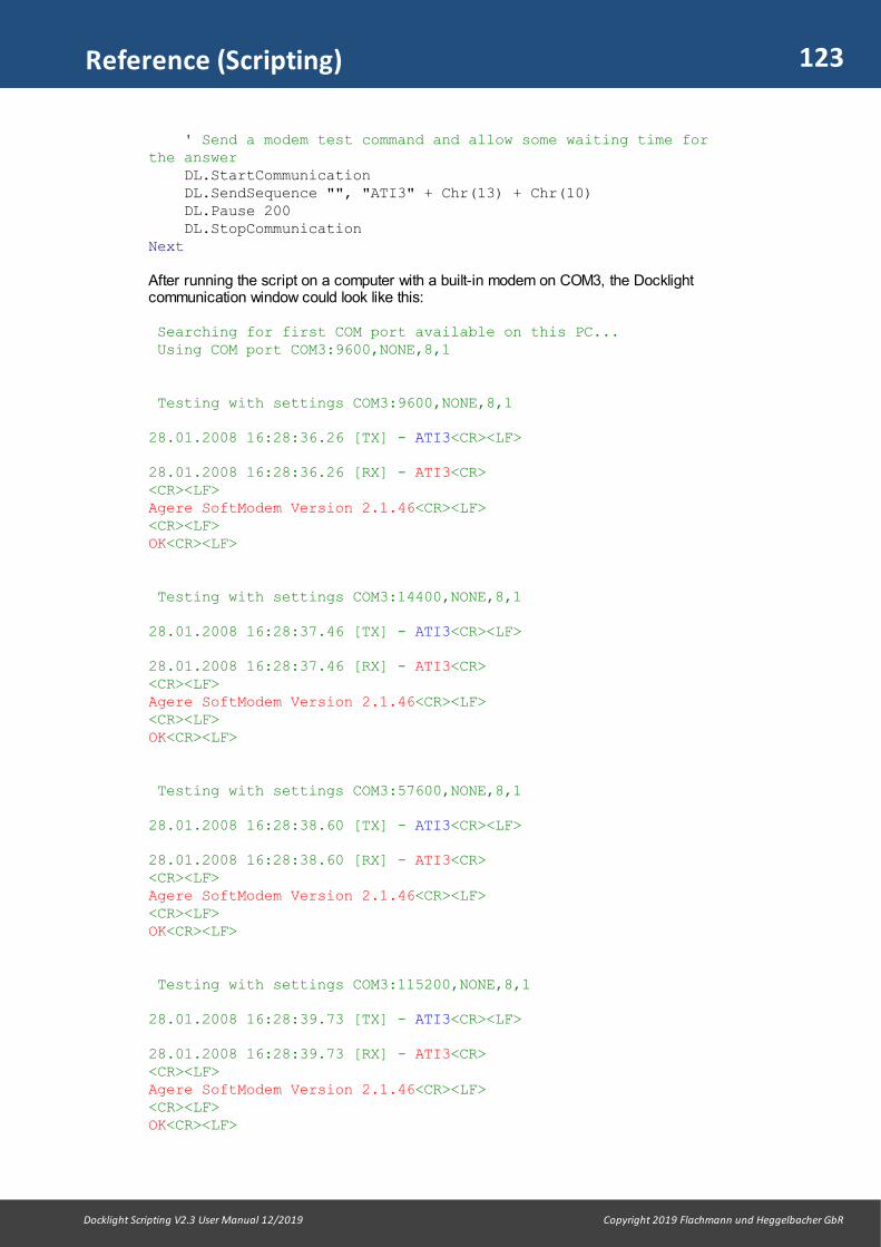
123
Docklight Scripting V2.3 User Manual 12/2019 Copyright 2019 Flachmann und Heggelbacher GbR
Reference (Scripting)
' Send a modem test command and allow some waiting time forthe answer DL.StartCommunication DL.SendSequence "", "ATI3" + Chr(13) + Chr(10) DL.Pause 200 DL.StopCommunicationNext
After running the script on a computer with a built-in modem on COM3, the Docklightcommunication window could look like this:
Searching for first COM port available on this PC... Using COM port COM3:9600,NONE,8,1 Testing with settings COM3:9600,NONE,8,1
28.01.2008 16:28:36.26 [TX] - ATI3<CR><LF>
28.01.2008 16:28:36.26 [RX] - ATI3<CR><CR><LF>Agere SoftModem Version 2.1.46<CR><LF><CR><LF>OK<CR><LF> Testing with settings COM3:14400,NONE,8,1
28.01.2008 16:28:37.46 [TX] - ATI3<CR><LF>
28.01.2008 16:28:37.46 [RX] - ATI3<CR><CR><LF>Agere SoftModem Version 2.1.46<CR><LF><CR><LF>OK<CR><LF> Testing with settings COM3:57600,NONE,8,1
28.01.2008 16:28:38.60 [TX] - ATI3<CR><LF>
28.01.2008 16:28:38.60 [RX] - ATI3<CR><CR><LF>Agere SoftModem Version 2.1.46<CR><LF><CR><LF>OK<CR><LF> Testing with settings COM3:115200,NONE,8,1
28.01.2008 16:28:39.73 [TX] - ATI3<CR><LF>
28.01.2008 16:28:39.73 [RX] - ATI3<CR><CR><LF>Agere SoftModem Version 2.1.46<CR><LF><CR><LF>OK<CR><LF>

124
Docklight Scripting V2.3 User Manual 12/2019 Copyright 2019 Flachmann und Heggelbacher GbR
Reference (Scripting)
10.2.2.15 SetContentsFilter
Use a different Contents Filter setting than the one defined in the Project Settings -Communication Filter dialog.
Return Value
Void
Syntax
DL.SetContentsFilter newContentsFilter
The SetContentsFilter method syntax has these parts:
Part Description
newContentsFilter
Required. Integer value to select the new filter:0 = Show all original communication data (channel 1 and channel 2) 1 = Show channel 1 or [TX] data only2 = Show channel 2 or [RX] data only3 = Hide all original serial data, show additional comments only
Remarks
After the script execution has ended, the Contents Filter is set to the original projectsetting defined in Project Settings - Communication Filter.
Example
' Requires the Docklight basic example project "PingPong" and aloopback on the chosen ' communication channel DL.OpenProject "PingPong"DL.ClearCommWindowsDL.SendSequence "Ping"DL.Pause 50DL.AddComment vbCrLf + "SetContentsFilter(1) " :DL.SetContentsFilter(1) DL.Pause 50DL.AddComment vbCrLf + "SetContentsFilter(2) " :DL.SetContentsFilter(2) DL.Pause 50DL.AddComment vbCrLf + "SetContentsFilter(3) " :DL.SetContentsFilter(3) DL.Pause 50
After running the script, the Docklight communication window could look like this:
7/30/2012 17:42:31.322 [TX] - 2D 2D 2D 2D 6F 20 50 69 6E 67 7/30/2012 17:42:31.326 [RX] - 2D 2D 2D 2D 6F 20 50 69 6E 67 "Ping" received 7/30/2012 17:42:31.350 [TX] - 6F 2D 2D 2D 2D 20 50 6F 6E 67 7/30/2012 17:42:31.352 [RX] - 6F 2D 2D 2D 2D 20 50 6F 6E 67 "Pong" received 7/30/2012 17:42:31.499 [TX] - 2D 2D 2D 2D 6F 20 50 69 6E 67 SetContentsFilter(1) "Ping" received
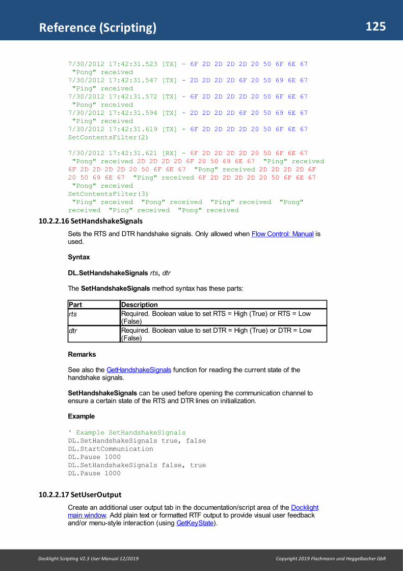
125
Docklight Scripting V2.3 User Manual 12/2019 Copyright 2019 Flachmann und Heggelbacher GbR
Reference (Scripting)
7/30/2012 17:42:31.523 [TX] - 6F 2D 2D 2D 2D 20 50 6F 6E 67 "Pong" received 7/30/2012 17:42:31.547 [TX] - 2D 2D 2D 2D 6F 20 50 69 6E 67 "Ping" received 7/30/2012 17:42:31.572 [TX] - 6F 2D 2D 2D 2D 20 50 6F 6E 67 "Pong" received 7/30/2012 17:42:31.594 [TX] - 2D 2D 2D 2D 6F 20 50 69 6E 67 "Ping" received 7/30/2012 17:42:31.619 [TX] - 6F 2D 2D 2D 2D 20 50 6F 6E 67 SetContentsFilter(2)
7/30/2012 17:42:31.621 [RX] - 6F 2D 2D 2D 2D 20 50 6F 6E 67 "Pong" received 2D 2D 2D 2D 6F 20 50 69 6E 67 "Ping" received6F 2D 2D 2D 2D 20 50 6F 6E 67 "Pong" received 2D 2D 2D 2D 6F20 50 69 6E 67 "Ping" received 6F 2D 2D 2D 2D 20 50 6F 6E 67 "Pong" received SetContentsFilter(3) "Ping" received "Pong" received "Ping" received "Pong"received "Ping" received "Pong" received
10.2.2.16 SetHandshakeSignals
Sets the RTS and DTR handshake signals. Only allowed when Flow Control: Manual isused.
Syntax
DL.SetHandshakeSignals rts, dtr
The SetHandshakeSignals method syntax has these parts:
Part Description
rts Required. Boolean value to set RTS = High (True) or RTS = Low(False)
dtr Required. Boolean value to set DTR = High (True) or DTR = Low(False)
Remarks
See also the GetHandshakeSignals function for reading the current state of thehandshake signals.
SetHandshakeSignals can be used before opening the communication channel toensure a certain state of the RTS and DTR lines on initialization.
Example
' Example SetHandshakeSignalsDL.SetHandshakeSignals true, falseDL.StartCommunicationDL.Pause 1000DL.SetHandshakeSignals false, trueDL.Pause 1000
10.2.2.17 SetUserOutput
Create an additional user output tab in the documentation/script area of the Docklightmain window. Add plain text or formatted RTF output to provide visual user feedbackand/or menu-style interaction (using GetKeyState).

126
Docklight Scripting V2.3 User Manual 12/2019 Copyright 2019 Flachmann und Heggelbacher GbR
Reference (Scripting)
Syntax
DL.SetUserOutput text [, rtfFormat] [, append] [, readFromFile]
The SetUserOutput method syntax has these parts:
Part Description
text Required. Your output to show or add.
If text is an empty string, the output tab is removed again from the Docklight main window .
rtfFormat Optional Boolean value.False (Default) = text is plain textTrue = text is a valid RTF document, e.g. the contents of a RTFdocument file.
append Optional Boolean value.True (Default) = add text to the already existing content.False = replace the existing output content with text .
readFromFile Optional Boolean value.False (Default) = text contains the actual text or RTF documentTrue = text is a file and its contents should be displayed.
NOTE: if a file does not exist or cannot be loaded, SetUserOutputuses an empty string instead and does not indicate an error.
Remarks
SetUserOutput can help you to create a customized user output or offer menu-styleuser interactions. An example could be choosing from different predefined tests in anautomated device testing rig.
See the SetUserOutput_Example.pts example script in theScriptSamples\Extras\SetUserOutput_Example folder for the different possibilities ofloading / adding formatted text.
Example
DL.SetUserOutput "" ' clear outputDL.Pause 1000 DL.SetUserOutput "A good old 'Hello World!'"DL.Pause 5000DL.SetUserOutput "... more text ..."DL.Pause 5000
' You can create your RTF document bits with Windows Wordpadand ' open the resulting .rtf file with Windows Notepad to see theRTF code.rtfExample ="{\rtf1\ansi\ansicpg1252\deff0{\fonttbl{\f0\fnil\fcharset0Harlow Solid Italic;}}{\colortbl ;\red75\green172\blue198;}\cf1\f0\fs32 A Curly Hello!\par}"DL.SetUserOutput "... something more colorful ..."DL.SetUserOutput rtfExample, True
DL.Pause 5000

127
Docklight Scripting V2.3 User Manual 12/2019 Copyright 2019 Flachmann und Heggelbacher GbR
Reference (Scripting)
DL.SetUserOutput "The End. Removing output tab soon...", False, FalseDL.Pause 5000DL.SetUserOutput ""
Example 2 (read RTF file and display)
DL.SetUserOutput "C:\mytext.rtf", True, False, True
10.2.2.18 SetWindowLayout
Controls the Docklight main window appearance, similar to the menu Tools >Minimize/Restore... and the F12 Hot Keys.
Syntax
DL.SetWindowLayout [ layout ]
The SetWindowLayout method syntax has these parts:
Part Description
layout Optional String argument. A combination of the following letters: S - sequence area visibleD - doc/script area visible
Default value is "SD" - show both the sequence lists and the doc/scriptarea.
Remarks
SetWindowLayout is useful when you have a ready-to-use script/project and the enduser should not be distracted by details of your Docklight project and script definitions.By hiding some areas of the Docklight main window, you can put the focus on theCommunication Window output, or a SetUserOutput display you created.
Example
' Example SetWindowLayout ' show communication window only. No doc/script area, noSend/Receive Sequence areaDL.SetWindowLayout "" DL.Pause 4000' show communication window and Send/Receive sequence lists,but no doc/script areaDL.SetWindowLayout "S" DL.Pause 4000' show everything (default, same as <layout> = "SD")DL.SetWindowLayout
10.2.2.19 ShellRun
Starts an external application or executes a Windows Shell operation.
Return Value
Integer
Syntax 1

128
Docklight Scripting V2.3 User Manual 12/2019 Copyright 2019 Flachmann und Heggelbacher GbR
Reference (Scripting)
result = DL.ShellRun(operation, file [, parameters] [, directory] [, showCmd])
The ShellRun method syntax 1 has these parts:
Part Description
operation Required. String which specifies the type of action to be performed,corresponding to the Windows ShellExecute lpOperation parameter. Commonly used values are:"open"- opens a file or a folder"print"- prints a file"edit" - launches an editor and opens the file for editingSee the Windows ShellExecute documentation for more values anddocumentation.
file Required. String with the path to the file on which to executeoperation.
parameters Optional. String value. If file is an executable, command-linearguments can be passed here.
directory Optional. String value. Defines the working directory for the action. Ifnot used, the current Docklight working directory is used.
showCmd Optional Integer value. Specifies the application appearance,corresponding to the Windows ShellExecute nShowCmd parameter.Default value is:10 - SW_SHOWDEFAULT other common values are:0 - SW_HIDE1 - SW_SHOWNORMAL2 - SW_SHOWMINIMIZED3 - SW_SHOWMAXIMIZED
Remarks (Syntax 1)
result contains the return value of Windows ShellExecute.
result is > 32 if successful.
See the example below for a definition of relevant error constants for result.
Syntax 2
result = DL.ShellRun("wait<timeout>", [, file] [, parameters] [, directory] [,showCmd])
The ShellRun method syntax 1 has these parts:
Part Description
"wait<timeout>" Instead of operation as in Syntax 1, use:"wait" - start an external application and wait for it to quitor"wait<timeout>", e.g. "wait60000" - start an external application andwait for it to quit, or for the specified timeout in milliseconds to expire.
fileparametersdirectory showCmd
same as in Syntax 1
Remarks (Syntax 2):
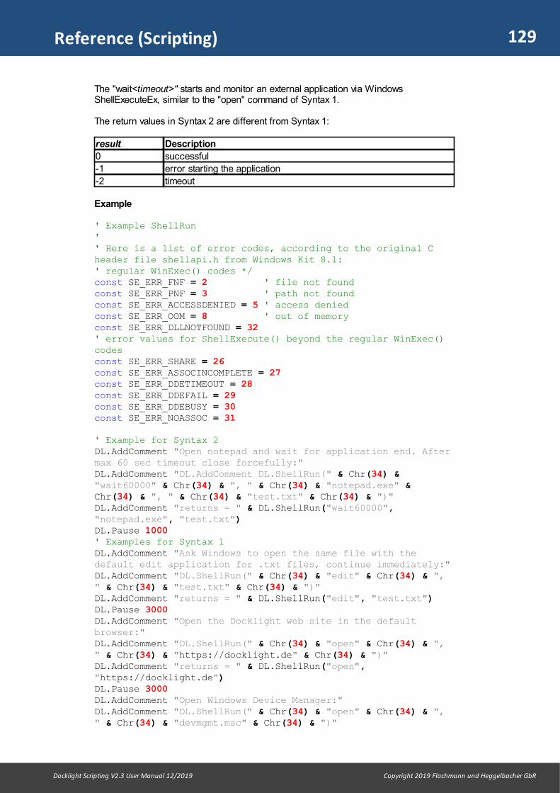
129
Docklight Scripting V2.3 User Manual 12/2019 Copyright 2019 Flachmann und Heggelbacher GbR
Reference (Scripting)
The "wait<timeout>" starts and monitor an external application via WindowsShellExecuteEx, similar to the "open" command of Syntax 1.
The return values in Syntax 2 are different from Syntax 1:
result Description
0 successful
-1 error starting the application
-2 timeout
Example
' Example ShellRun' ' Here is a list of error codes, according to the original Cheader file shellapi.h from Windows Kit 8.1:' regular WinExec() codes */const SE_ERR_FNF = 2 ' file not foundconst SE_ERR_PNF = 3 ' path not foundconst SE_ERR_ACCESSDENIED = 5 ' access deniedconst SE_ERR_OOM = 8 ' out of memoryconst SE_ERR_DLLNOTFOUND = 32' error values for ShellExecute() beyond the regular WinExec()codesconst SE_ERR_SHARE = 26const SE_ERR_ASSOCINCOMPLETE = 27const SE_ERR_DDETIMEOUT = 28const SE_ERR_DDEFAIL = 29const SE_ERR_DDEBUSY = 30const SE_ERR_NOASSOC = 31
' Example for Syntax 2DL.AddComment "Open notepad and wait for application end. Aftermax 60 sec timeout close forcefully:"DL.AddComment "DL.AddComment DL.ShellRun(" & Chr(34) &"wait60000" & Chr(34) & ", " & Chr(34) & "notepad.exe" &Chr(34) & ", " & Chr(34) & "test.txt" & Chr(34) & ")"DL.AddComment "returns = " & DL.ShellRun("wait60000","notepad.exe", "test.txt")DL.Pause 1000' Examples for Syntax 1DL.AddComment "Ask Windows to open the same file with thedefault edit application for .txt files, continue immediately:"DL.AddComment "DL.ShellRun(" & Chr(34) & "edit" & Chr(34) & "," & Chr(34) & "test.txt" & Chr(34) & ")"DL.AddComment "returns = " & DL.ShellRun("edit", "test.txt")DL.Pause 3000DL.AddComment "Open the Docklight web site in the defaultbrowser:"DL.AddComment "DL.ShellRun(" & Chr(34) & "open" & Chr(34) & "," & Chr(34) & "https://docklight.de" & Chr(34) & ")"DL.AddComment "returns = " & DL.ShellRun("open","https://docklight.de")DL.Pause 3000DL.AddComment "Open Windows Device Manager:"DL.AddComment "DL.ShellRun(" & Chr(34) & "open" & Chr(34) & "," & Chr(34) & "devmgmt.msc" & Chr(34) & ")"
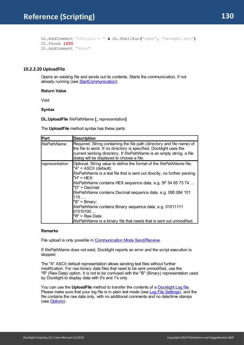
130
Docklight Scripting V2.3 User Manual 12/2019 Copyright 2019 Flachmann und Heggelbacher GbR
Reference (Scripting)
DL.AddComment "returns = " & DL.ShellRun("open", "devmgmt.msc")DL.Pause 1000DL.AddComment "done"
10.2.2.20 UploadFile
Opens an existing file and sends out its contents. Starts the communication, if notalready running (see StartCommunication).
Return Value
Void
Syntax
DL.UploadFile filePathName [, representation]
The UploadFile method syntax has these parts:
Part Description
filePathName Required. String containing the file path (directory and file name) ofthe file to send. If no directory is specified, Docklight uses thecurrent working directory. If filePathName is an empty string, a filedialog will be displayed to choose a file.
representation Optional. String value to define the format of the filePathName file. "A" = ASCII (default): filePathName is a text file that is sent out directly, no further parsing."H" = HEX: filePathName contains HEX sequence data, e.g. 5F 54 65 73 74 ..."D" = Decimal: filePathName contains Decimal sequence data, e.g. 095 084 101115 ..."B" = Binary:filePathName contains Binary sequence data, e.g. 0101111101010100 ..."R" = Raw Data:filePathName is a binary file that needs that is sent out unmodified.
Remarks
File upload is only possible in Communication Mode Send/Receive.
If filePathName does not exist, Docklight reports an error and the script execution isstopped.
The "A" ASCII default representation allows sending text files without furthermodification. For raw binary data files that need to be sent unmodified, use the"R" (Raw Data) option. It is not to be confused with the "B" (Binary) representation usedby Docklight to display data with 0's and 1's only.
You can use the UploadFile method to transfer the contents of a Docklight Log file.Please make sure that your log file is in plain text mode (see Log File Settings), and thefile contains the raw data only, with no additional comments and no date/time stamps(see Options).

131
Docklight Scripting V2.3 User Manual 12/2019 Copyright 2019 Flachmann und Heggelbacher GbR
Reference (Scripting)
The UploadFile method does not support specific compiler output file formats, such as"Intel HEX File". If you have any specific requirements, please contact our e-mailsupport.
NOTE: The data is sent in blocks of max. 512 bytes. If you send a Send Sequencemanually during a file upload, the sequence will be sent between one of these blocksand will corrupt the data transmission.
Example
' Example Upload File
' Send a text fileDL.UploadFile "helloworld.txt", "A"
' Send raw binary data file directlyDL.UploadFile "test.dat", "R"
' Parse and send a HEX data fileDL.UploadFile "hexfile.txt", "H"
10.2.3 Properties
10.2.3.1 NoOfSendSequences
Returns the number of Send Sequences defined in the current Docklight project.
Return Value
Integer
Syntax
result = DL.NoOfSendSequences
Remarks
The NoOfSendSequences property is very useful to create loop structures that makeuse of all Send Sequences available. See the example below.
Example
' Example NoOfSendSequences
' Send out all Send Sequences defined, with a 1 seconds delay' between the individual sequencesFor i = 0 To (DL.NoOfSendSequences - 1) DL.SendSequence i DL.Pause 1000Next
10.2.3.2 NoOfReceiveSequences
Returns the number of Receive Sequences defined in the current Docklight project.
Return Value
Integer
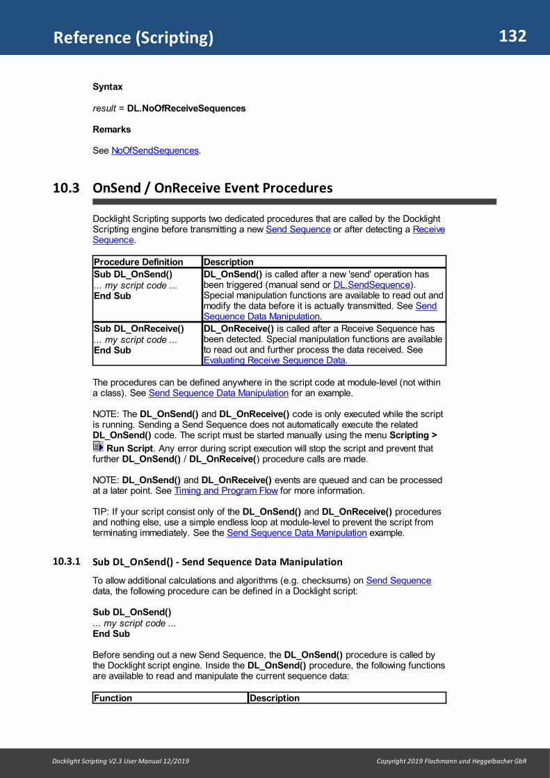
132
Docklight Scripting V2.3 User Manual 12/2019 Copyright 2019 Flachmann und Heggelbacher GbR
Reference (Scripting)
Syntax
result = DL.NoOfReceiveSequences
Remarks
See NoOfSendSequences.
10.3 OnSend / OnReceive Event Procedures
Docklight Scripting supports two dedicated procedures that are called by the DocklightScripting engine before transmitting a new Send Sequence or after detecting a ReceiveSequence.
Procedure Definition Description
Sub DL_OnSend()... my script code ...End Sub
DL_OnSend() is called after a new 'send' operation hasbeen triggered (manual send or DL.SendSequence).Special manipulation functions are available to read out andmodify the data before it is actually transmitted. See SendSequence Data Manipulation.
Sub DL_OnReceive()... my script code ...End Sub
DL_OnReceive() is called after a Receive Sequence hasbeen detected. Special manipulation functions are availableto read out and further process the data received. SeeEvaluating Receive Sequence Data.
The procedures can be defined anywhere in the script code at module-level (not withina class). See Send Sequence Data Manipulation for an example.
NOTE: The DL_OnSend() and DL_OnReceive() code is only executed while the scriptis running. Sending a Send Sequence does not automatically execute the relatedDL_OnSend() code. The script must be started manually using the menu Scripting >
Run Script. Any error during script execution will stop the script and prevent thatfurther DL_OnSend() / DL_OnReceive() procedure calls are made.
NOTE: DL_OnSend() and DL_OnReceive() events are queued and can be processedat a later point. See Timing and Program Flow for more information.
TIP: If your script consist only of the DL_OnSend() and DL_OnReceive() proceduresand nothing else, use a simple endless loop at module-level to prevent the script fromterminating immediately. See the Send Sequence Data Manipulation example.
10.3.1 Sub DL_OnSend() - Send Sequence Data Manipulation
To allow additional calculations and algorithms (e.g. checksums) on Send Sequencedata, the following procedure can be defined in a Docklight script:
Sub DL_OnSend()... my script code ...End Sub
Before sending out a new Send Sequence, the DL_OnSend() procedure is called bythe Docklight script engine. Inside the DL_OnSend() procedure, the following functionsare available to read and manipulate the current sequence data:
Function Description
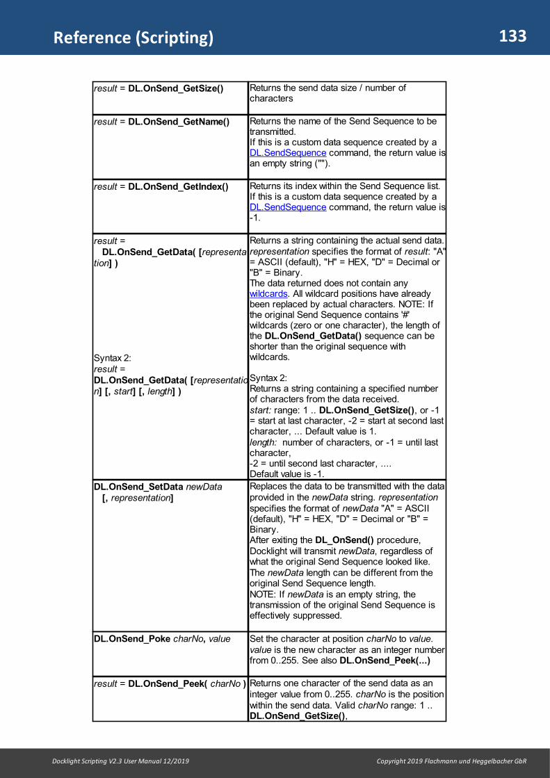
133
Docklight Scripting V2.3 User Manual 12/2019 Copyright 2019 Flachmann und Heggelbacher GbR
Reference (Scripting)
result = DL.OnSend_GetSize() Returns the send data size / number ofcharacters
result = DL.OnSend_GetName() Returns the name of the Send Sequence to betransmitted. If this is a custom data sequence created by aDL.SendSequence command, the return value isan empty string ("").
result = DL.OnSend_GetIndex() Returns its index within the Send Sequence list.If this is a custom data sequence created by aDL.SendSequence command, the return value is-1.
result = DL.OnSend_GetData( [representation] )
Syntax 2:result =DL.OnSend_GetData( [representation] [, start] [, length] )
Returns a string containing the actual send data.representation specifies the format of result: "A"= ASCII (default), "H" = HEX, "D" = Decimal or"B" = Binary. The data returned does not contain anywildcards. All wildcard positions have alreadybeen replaced by actual characters. NOTE: Ifthe original Send Sequence contains '#'wildcards (zero or one character), the length ofthe DL.OnSend_GetData() sequence can beshorter than the original sequence withwildcards.
Syntax 2: Returns a string containing a specified numberof characters from the data received. start: range: 1 .. DL.OnSend_GetSize(), or -1= start at last character, -2 = start at second lastcharacter, ... Default value is 1.length: number of characters, or -1 = until lastcharacter, -2 = until second last character, .... Default value is -1.
DL.OnSend_SetData newData [, representation]
Replaces the data to be transmitted with the dataprovided in the newData string. representationspecifies the format of newData "A" = ASCII(default), "H" = HEX, "D" = Decimal or "B" =Binary. After exiting the DL_OnSend() procedure,Docklight will transmit newData, regardless ofwhat the original Send Sequence looked like.The newData length can be different from theoriginal Send Sequence length. NOTE: If newData is an empty string, thetransmission of the original Send Sequence iseffectively suppressed.
DL.OnSend_Poke charNo, value Set the character at position charNo to value.value is the new character as an integer numberfrom 0..255. See also DL.OnSend_Peek(...)
result = DL.OnSend_Peek( charNo ) Returns one character of the send data as aninteger value from 0..255. charNo is the positionwithin the send data. Valid charNo range: 1 ..DL.OnSend_GetSize(),

134
Docklight Scripting V2.3 User Manual 12/2019 Copyright 2019 Flachmann und Heggelbacher GbR
Reference (Scripting)
Syntax 2:result = DL.OnSend_Peek( charNo,representation )
or -1 = start at last character, -2 = start atsecond last character, ...
Syntax 2:Returns a string instead of an integer value.representation specifies the format: "A" = ASCII, "H" = HEX, "D" = Decimal or "B" =Binary.
Remarks
Using the DL.OnSend_GetSize(), DL.OnSend_Peek(..) and DL.OnSend_Pokefunctions, checksum calculations and other algorithms can be easily implemented. Seethe example below.
The DL_OnSend() procedure is only executed while the script is running. Whileexecuting the DL_OnSend() code, no further communication processing and displayupdates are performed. To avoid performance and timing problems, keep the executiontime low. Avoid nested loops for example, and do not perform time-consumingcalculations.
See Timing and Program Flow for some insight on how Docklight handles send dataevents and executes the DL_OnSend() code section.
Example
' Example DL_OnSend() event code
' Predefined Send Sequences' (0) Test: TestX<CR><NUL>
' Endless loop to prevent the script from terminatingimmediatelyDo DL.Pause 1 ' (the pause reduces CPU load while idle)Loop
Sub DL_OnSend() ' Simple checksum: Last byte of sequence ' is a checksum on all previous bytes, mod 256 seqSize = DL.OnSend_GetSize() ' we need at least a three-byte sequence If seqSize > 2 Then
' instead of the "X" after Test, put a random character DL.OnSend_Poke seqSize - 2, 65 + Rnd * 25 ' calculate a simple checksum on the new sequence
chksumHex = DL.CalcChecksum("MOD256",DL.OnSend_GetData("H"), "H", 1, seqSize -1) ' Overwrite the last character of the Send Sequencewith the actual checksum value DL.OnSend_Poke seqSize, CInt("&h" + chkSumHex) ' Using the Peek function for additional documentation
DL.AddComment vbCrLf & vbCrLf DL.AddComment "Checksum on", False, False For i = 1 To seqSize - 1 DL.AddComment " " & DL.OnSend_Peek(i, "H"), False,False
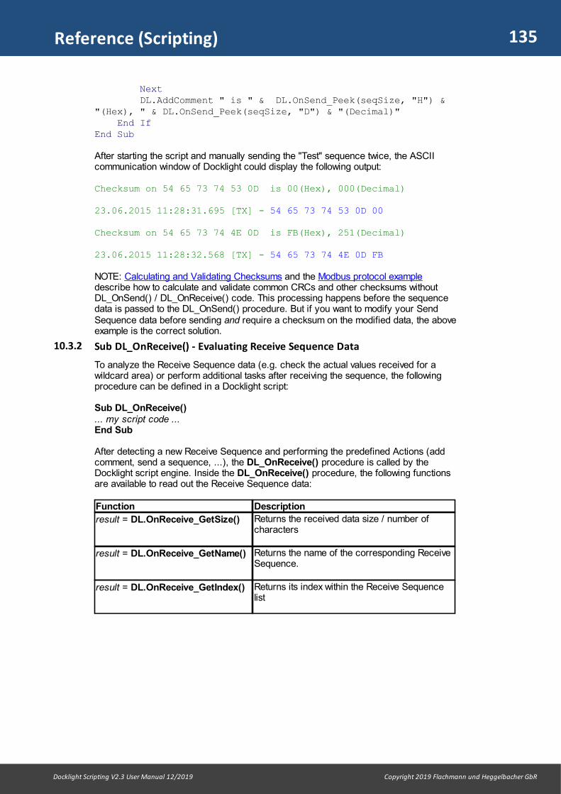
135
Docklight Scripting V2.3 User Manual 12/2019 Copyright 2019 Flachmann und Heggelbacher GbR
Reference (Scripting)
Next DL.AddComment " is " & DL.OnSend_Peek(seqSize, "H") &"(Hex), " & DL.OnSend_Peek(seqSize, "D") & "(Decimal)" End IfEnd Sub
After starting the script and manually sending the "Test" sequence twice, the ASCIIcommunication window of Docklight could display the following output:
Checksum on 54 65 73 74 53 0D is 00(Hex), 000(Decimal)
23.06.2015 11:28:31.695 [TX] - 54 65 73 74 53 0D 00
Checksum on 54 65 73 74 4E 0D is FB(Hex), 251(Decimal)
23.06.2015 11:28:32.568 [TX] - 54 65 73 74 4E 0D FB
NOTE: Calculating and Validating Checksums and the Modbus protocol exampledescribe how to calculate and validate common CRCs and other checksums withoutDL_OnSend() / DL_OnReceive() code. This processing happens before the sequencedata is passed to the DL_OnSend() procedure. But if you want to modify your SendSequence data before sending and require a checksum on the modified data, the aboveexample is the correct solution.
10.3.2 Sub DL_OnReceive() - Evaluating Receive Sequence Data
To analyze the Receive Sequence data (e.g. check the actual values received for awildcard area) or perform additional tasks after receiving the sequence, the followingprocedure can be defined in a Docklight script:
Sub DL_OnReceive()... my script code ...End Sub
After detecting a new Receive Sequence and performing the predefined Actions (addcomment, send a sequence, ...), the DL_OnReceive() procedure is called by theDocklight script engine. Inside the DL_OnReceive() procedure, the following functionsare available to read out the Receive Sequence data:
Function Description
result = DL.OnReceive_GetSize() Returns the received data size / number ofcharacters
result = DL.OnReceive_GetName() Returns the name of the corresponding ReceiveSequence.
result = DL.OnReceive_GetIndex() Returns its index within the Receive Sequencelist

136
Docklight Scripting V2.3 User Manual 12/2019 Copyright 2019 Flachmann und Heggelbacher GbR
Reference (Scripting)
result =DL.OnReceive_GetData( [representation] )
Syntax 2:result =DL.OnReceive_GetData( [representation] [, start] [, length] )
Returns a string containing the actual datareceived. representation specifies therepresentation of result: "A" = ASCII (default),"H" = HEX, "D" = Decimal or "B" = Binary. The data returned does not contain anywildcards. At wildcard positions, the actualcharacters received are returned. NOTE: If the original Receive Sequencecontains '#' wildcards (zero or one character),the length of the DL.OnReceive _GetData()sequence can be shorter than the originalsequence with wildcards.
Syntax 2: Returns a string containing a specified numberof characters from the data received. start: range: 1 .. DL.OnReceive_GetSize(), or -1 = start at last character, -2 = start at secondlast character, ... Default value is 1.
length: number of characters, or -1 = until lastcharacter, -2 = until second last character, .... Default value is -1.
result =DL.OnReceive_GetChannel()
Returns the communication channel number onwhich this sequence has been detected. InCommunication Mode "Monitoring", the returnvalue is 1 or 2. In Communication ModeSend/Receive, the return value is 2 always (RXchannel).
result =DL.OnReceive_Peek( charNo )
Syntax 2:result =DL.OnReceive_Peek( charNo,representation )
Returns one character of the received data asan integer value from 0..255 charNo is the position within the received data.Valid charNo range: 1 ..DL.OnReceive_GetSize(), or -1 = start at lastcharacter, -2 = start at second last character, ...
Syntax 2:Returns a string instead of an integer value.representation specifies the format: "A" = ASCII, "H" = HEX, "D" = Decimal or "B" =Binary.
myDateTime =DL.OnReceive_GetDateTime()
milliseconds =DL.OnReceive_GetMilliseconds()
These functions return the actual Docklightdate/time stamp when this Receive Sequencewas triggered. The result is stored in twoseparate VBScript standard data types:myDateTime: VBScript Date value with theDate/Time in 1 seconds resolutionmilliseconds: Integer value with thecorresponding milliseconds information from0..999
Remarks
The DL.OnReceive_GetData() method is a good way to analyze the actual datareceived when you are using ASCII protocols with printing characters only. If yourequire the HEX or decimal value of individual characters, you may use the

137
Docklight Scripting V2.3 User Manual 12/2019 Copyright 2019 Flachmann und Heggelbacher GbR
Reference (Scripting)
DL.OnReceive_Peek( .. ) function as a convenient alternative. See the DL_OnSend()event procedure for a related example.
The DL_OnReceive() procedure is only executed while the script is running. Whileexecuting the DL_OnReceive() code, no further communication processing and displayupdates are performed. To avoid performance and timing problems, keep the executiontime low. Avoid nested loops for example, and do not perform time-consumingcalculations.
DL_OnReceive() procedures are not executed while a Pause or a WaitForSequencemethod is blocking the program flow. If a Receive Sequence is detected, theDL_OnReceive() call is queued and executed after Pause (or WaitForSequence)returns. See Example 2 below for a workaround to this problem.
See also Timing and Program Flow for some insight on how Docklight handles receivedata events and executes the DL_OnReceive() code section.
Example
' Example DL_OnReceive() event code'' Predefined Send Sequence' (0) Send Value:' VALUE=<?><?><CR><LF>'' Predefined Receive Sequence' (0) Value Received:' VALUE=<?><?><CR><LF>'' Run this test on a COM port with a loopback connector' (TX connected to RX of the same port).
finished = FalseDL.ClearCommWindowsDo DL.Pause 1 ' (the pause reduces CPU load while idle)Loop Until finished
Sub DL_OnReceive() If DL.OnReceive_GetName() = "Value Received" Then
DL.AddComment "Value received = " &DL.OnReceive_GetData("A", 7, -3) ' Read the value from the receive data, but only thechanging "value" part myValue = Mid(DL.OnReceive_GetData(), 7, 2) ' Ensure this is a numeric value If IsNumeric(myValue) Then ' increase myValue = myValue + 1 If myValue < 100 Then ' If the value is still below 100, send it outagain newValueStr = CStr(myValue) DL.SendSequence "Send Value", newValueStr Else DL.AddComment "VALUE=99, stopping..." finished = True
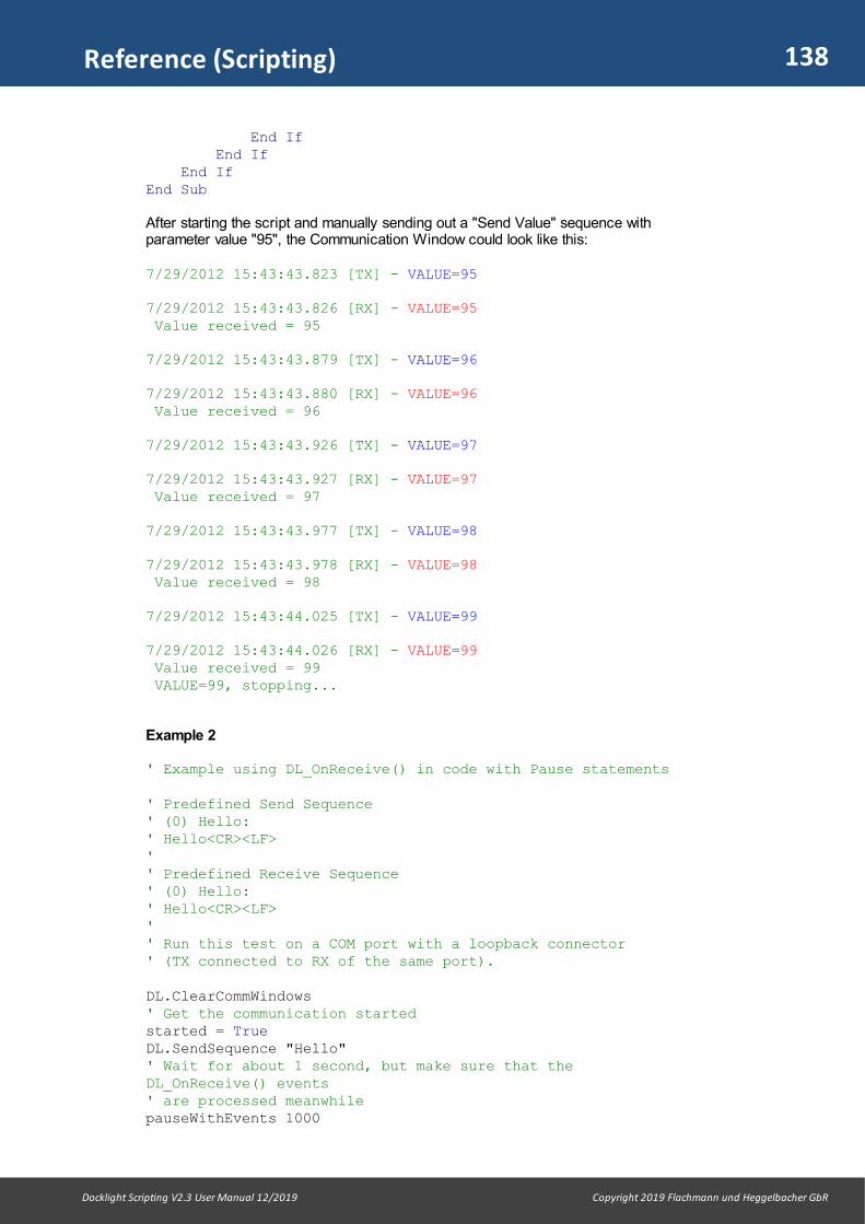
138
Docklight Scripting V2.3 User Manual 12/2019 Copyright 2019 Flachmann und Heggelbacher GbR
Reference (Scripting)
End If End If End IfEnd Sub
After starting the script and manually sending out a "Send Value" sequence withparameter value "95", the Communication Window could look like this:
7/29/2012 15:43:43.823 [TX] - VALUE=95
7/29/2012 15:43:43.826 [RX] - VALUE=95 Value received = 95
7/29/2012 15:43:43.879 [TX] - VALUE=96
7/29/2012 15:43:43.880 [RX] - VALUE=96 Value received = 96
7/29/2012 15:43:43.926 [TX] - VALUE=97
7/29/2012 15:43:43.927 [RX] - VALUE=97 Value received = 97
7/29/2012 15:43:43.977 [TX] - VALUE=98
7/29/2012 15:43:43.978 [RX] - VALUE=98 Value received = 98
7/29/2012 15:43:44.025 [TX] - VALUE=99
7/29/2012 15:43:44.026 [RX] - VALUE=99 Value received = 99 VALUE=99, stopping...
Example 2
' Example using DL_OnReceive() in code with Pause statements
' Predefined Send Sequence' (0) Hello:' Hello<CR><LF>'' Predefined Receive Sequence' (0) Hello:' Hello<CR><LF>'' Run this test on a COM port with a loopback connector' (TX connected to RX of the same port).
DL.ClearCommWindows' Get the communication startedstarted = TrueDL.SendSequence "Hello"' Wait for about 1 second, but make sure that theDL_OnReceive() events' are processed meanwhilepauseWithEvents 1000
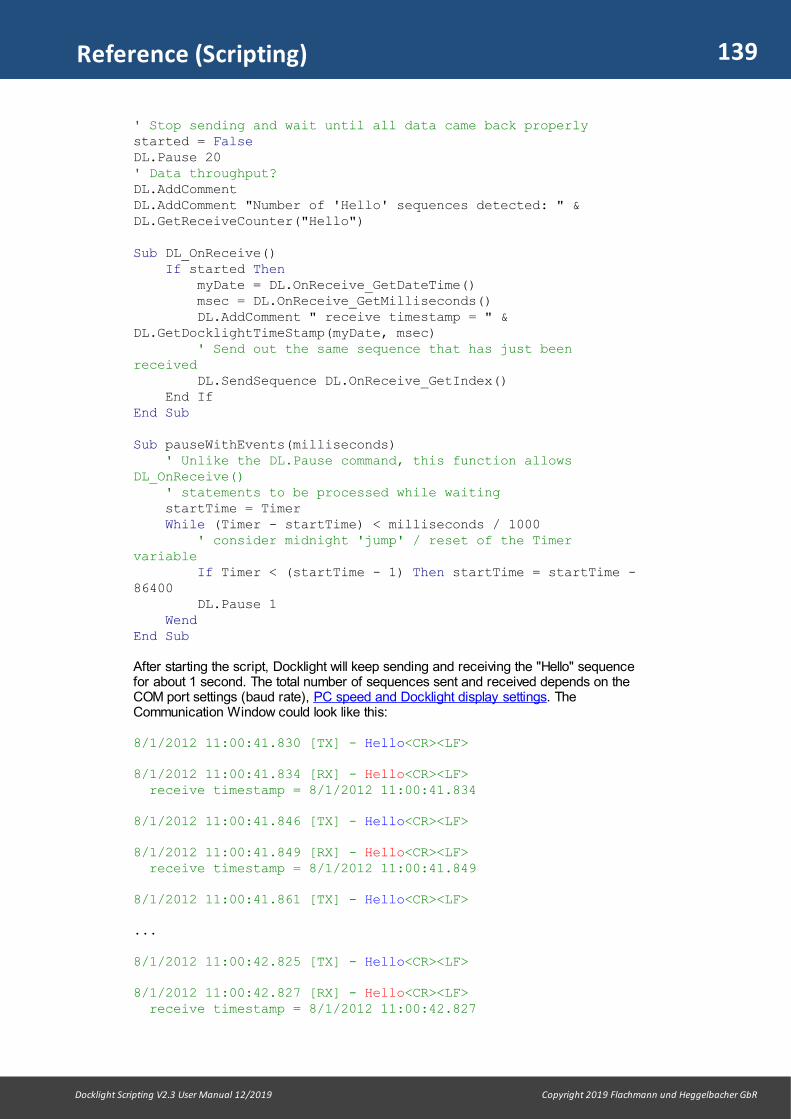
139
Docklight Scripting V2.3 User Manual 12/2019 Copyright 2019 Flachmann und Heggelbacher GbR
Reference (Scripting)
' Stop sending and wait until all data came back properlystarted = FalseDL.Pause 20' Data throughput?DL.AddCommentDL.AddComment "Number of 'Hello' sequences detected: " &DL.GetReceiveCounter("Hello")
Sub DL_OnReceive() If started Then myDate = DL.OnReceive_GetDateTime() msec = DL.OnReceive_GetMilliseconds() DL.AddComment " receive timestamp = " &DL.GetDocklightTimeStamp(myDate, msec) ' Send out the same sequence that has just beenreceived
DL.SendSequence DL.OnReceive_GetIndex() End IfEnd Sub
Sub pauseWithEvents(milliseconds) ' Unlike the DL.Pause command, this function allowsDL_OnReceive() ' statements to be processed while waiting startTime = Timer While (Timer - startTime) < milliseconds / 1000 ' consider midnight 'jump' / reset of the Timervariable If Timer < (startTime - 1) Then startTime = startTime -86400 DL.Pause 1 WendEnd Sub
After starting the script, Docklight will keep sending and receiving the "Hello" sequencefor about 1 second. The total number of sequences sent and received depends on theCOM port settings (baud rate), PC speed and Docklight display settings. TheCommunication Window could look like this:
8/1/2012 11:00:41.830 [TX] - Hello<CR><LF>
8/1/2012 11:00:41.834 [RX] - Hello<CR><LF> receive timestamp = 8/1/2012 11:00:41.834
8/1/2012 11:00:41.846 [TX] - Hello<CR><LF>
8/1/2012 11:00:41.849 [RX] - Hello<CR><LF> receive timestamp = 8/1/2012 11:00:41.849
8/1/2012 11:00:41.861 [TX] - Hello<CR><LF>
...
8/1/2012 11:00:42.825 [TX] - Hello<CR><LF>
8/1/2012 11:00:42.827 [RX] - Hello<CR><LF> receive timestamp = 8/1/2012 11:00:42.827

140
Docklight Scripting V2.3 User Manual 12/2019 Copyright 2019 Flachmann und Heggelbacher GbR
Reference (Scripting)
8/1/2012 11:00:42.839 [TX] - Hello<CR><LF>
8/1/2012 11:00:42.841 [RX] - Hello<CR><LF> receive timestamp = 8/1/2012 11:00:42.841
8/1/2012 11:00:42.852 [TX] - Hello<CR><LF>
8/1/2012 11:00:42.855 [RX] - Hello<CR><LF> Number of 'Hello' sequences detected: 70
Example 3
' Example using Sub DL_OnReceive() to wait for ANY sequence
found = FalsefoundName = ""foundDate = NowfoundMSec = 0
Do DL.Pause 1 ' (the pause reduces CPU load while idle)Loop Until found
DL.AddCommentDL.AddComment "Sequence received: " & foundName DL.AddComment "Date/Time received: " &DL.GetDocklightTimeStamp(foundDate, foundMSec)
Sub DL_OnReceive() If Not found Then found = True foundName = DL.OnReceive_GetName() foundDate = DL.OnReceive_GetDateTime() foundMSec = DL.OnReceive_GetMilliseconds() End IfEnd Sub
10.3.3 OnSend / OnReceive - Timing and Program Flow
Sub DL_OnSend() Timing
While a script is running, the DL_OnSend() event procedure is executed once for eachnew Send Sequence. This applies to both, sequences sent by clicking the "Send"button, and DL.SendSequence calls.
The DL_OnSend() event procedure is only entered after the current line of script codehas been executed. "Send" requests are buffered in the meantime.
The sequence diagram below shows the resulting timing behavior for an example withone 'manual' send request (sequence1), and a second Send Sequence triggered byscript code (DL.SendSequence "sequence2").

141
Docklight Scripting V2.3 User Manual 12/2019 Copyright 2019 Flachmann und Heggelbacher GbR
Reference (Scripting)
Sub DL_OnReceive() Timing
Similar to DL_OnSend(), the DL_OnReceive() event procedure is not executedimmediately after Docklight has detected a new Receive Sequence match. Instead, theevents are buffered and executed after the current line of script code has beenexecuted.
The sequence diagram below shows the timing for an example where two differentReceive Sequences are detected in one go, and the DL_OnReceive() code is executedat a later point.
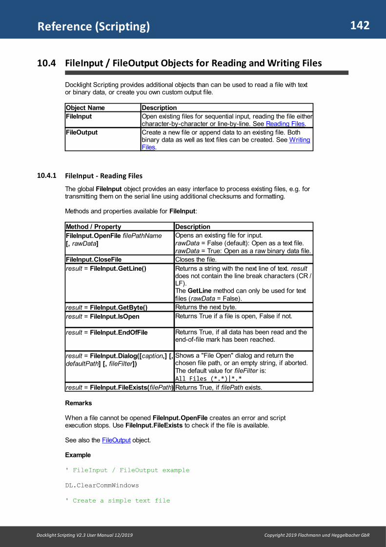
142
Docklight Scripting V2.3 User Manual 12/2019 Copyright 2019 Flachmann und Heggelbacher GbR
Reference (Scripting)
10.4 FileInput / FileOutput Objects for Reading and Writing Files
Docklight Scripting provides additional objects than can be used to read a file with textor binary data, or create you own custom output file.
Object Name Description
FileInput Open existing files for sequential input, reading the file eithercharacter-by-character or line-by-line. See Reading Files.
FileOutput Create a new file or append data to an existing file. Bothbinary data as well as text files can be created. See WritingFiles.
10.4.1 FileInput - Reading Files
The global FileInput object provides an easy interface to process existing files, e.g. fortransmitting them on the serial line using additional checksums and formatting.
Methods and properties available for FileInput:
Method / Property Description
FileInput.OpenFile filePathName [, rawData]
Opens an existing file for input. rawData = False (default): Open as a text file.rawData = True: Open as a raw binary data file.
FileInput.CloseFile Closes the file.
result = FileInput.GetLine() Returns a string with the next line of text. resultdoes not contain the line break characters (CR /LF). The GetLine method can only be used for textfiles (rawData = False).
result = FileInput.GetByte() Returns the next byte.
result = FileInput.IsOpen Returns True if a file is open, False if not.
result = FileInput.EndOfFile Returns True, if all data has been read and theend-of-file mark has been reached.
result = FileInput.Dialog([caption,] [,defaultPath] [, fileFilter])
Shows a "File Open" dialog and return thechosen file path, or an empty string, if aborted.The default value for fileFilter is: All Files (*.*)|*.*
result = FileInput.FileExists(filePath) Returns True, if filePath exists.
Remarks
When a file cannot be opened FileInput.OpenFile creates an error and scriptexecution stops. Use FileInput.FileExists to check if the file is available.
See also the FileOutput object.
Example
' FileInput / FileOutput example
DL.ClearCommWindows
' Create a simple text file

143
Docklight Scripting V2.3 User Manual 12/2019 Copyright 2019 Flachmann und Heggelbacher GbR
Reference (Scripting)
FileOutput.CreateFile "C:\test.txt"FileOutput.WriteLine "Hello World!"FileOutput.WriteLine "Goodbye, World!"FileOutput.CloseFile
' Open the file and print its contentspath = FileInput.Dialog("Open a text for Docklight", "C:\","Text Files (*.txt)|*.txt")If Len(path) > 0 Then DL.AddComment "Reading text file..." FileInput.OpenFile "C:\test.txt" Do Until FileInput.EndOfFile DL.AddComment FileInput.GetLine() Loop FileInput.CloseFileEnd If
' Now try a raw data fileFileOutput.CreateFile "C:\test.bin", TrueFor i = 0 To 255 FileOutput.WriteByte iNextFileOutput.CloseFile
' And load it...DL.AddCommentDL.AddComment "Reading raw data file..."FileInput.OpenFile "C:\test.bin", TrueDo Until FileInput.EndOfFile DL.AddComment Right("0" + Hex(FileInput.GetByte()), 2) + "", False, FalseLoopFileInput.CloseFile
The above script code produces the following output in the Docklight communicationwindow:
Create text file C:\test.txt Reading text file: C:\test.txt Hello World! Goodbye, World! Create binary data file C:\test.txt Reading raw data file...00 01 02 03 04 05 06 07 08 09 0A 0B 0C 0D 0E 0F 10 11 12 13 1415 16 17 18 19 1A 1B 1C 1D 1E 1F 20 21 22 23 24 25 26 27 28 292A 2B 2C 2D 2E 2F 30 31 32 33 34 35 36 37 38 39 3A 3B 3C 3D 3E3F 40 41 42 43 44 45 46 47 48 49 4A 4B 4C 4D 4E 4F 50 51 52 5354 55 56 57 58 59 5A 5B 5C 5D 5E 5F 60 61 62 63 64 65 66 67 6869 6A 6B 6C 6D 6E 6F 70 71 72 73 74 75 76 77 78 79 7A 7B 7C 7D7E 7F 80 81 82 83 84 85 86 87 88 89 8A 8B 8C 8D 8E 8F 90 91 9293 94 95 96 97 98 99 9A 9B 9C 9D 9E 9F A0 A1 A2 A3 A4 A5 A6 A7A8 A9 AA AB AC AD AE AF B0 B1 B2 B3 B4 B5 B6 B7 B8 B9 BA BB BCBD BE BF C0 C1 C2 C3 C4 C5 C6 C7 C8 C9 CA CB CC CD CE CF D0 D1D2 D3 D4 D5 D6 D7 D8 D9 DA DB DC DD DE DF E0 E1 E2 E3 E4 E5 E6E7 E8 E9 EA EB EC ED EE EF F0 F1 F2 F3 F4 F5 F6 F7 F8 F9 FA FBFC FD FE FF

144
Docklight Scripting V2.3 User Manual 12/2019 Copyright 2019 Flachmann und Heggelbacher GbR
Reference (Scripting)
10.4.2 FileOutput - Writing Files
The global FileOutput object provides an easy interface to create files, e.g. for writingcustom data formats.
Methods and properties available for FileOutput:
Method / Property Description
FileOutput.CreateFile filePathName [, rawData] [, appendData]
Create a new output file. rawData = False (default): Open as a text file.rawData = True: Open as a raw binary data file.appendData = False (default): Overwrite file, ifexists.appendData = True: Append data to an existingfile.
FileOutput.CloseFile Closes the file.
FileOutput.WriteLine data [, appendLineBreak]
Write the string data to the file.appendLineBreak = True (default): Append aCR / LF line break after the data stringappendLineBreak = False: don't create a linebreakThe WriteLine method can only be used for textfiles (rawData = False).
FileOutput.WriteByte data Write the byte data to the file.
result = FileOutput.IsOpen Returns True if a file is open, False if not.
result = FileOutput.Dialog([caption][, defaultPath] [, fileFilter])
Shows a "File Save" dialog and return thechosen file path, or an empty string, if aborted.The default value for fileFilter is:All Files (*.*)|*.*
result =FileOutput.FileExists(filePath)
Returns True, if filePath exists.
Remarks
When FileInput.CreateFile cannot open the file, it produces an error and scriptexecution stops.
See the FileInput object for an example.
10.4.3 Multiple Input Files / Multiple Output Files
If you require to read or write more than one file at a time, you can open up to 4 inputfiles and 4 output files simultaneously, using additional global objects besides FileInputand FileOutput. The list of available objects is:
Object Name Description
FileInputFileInput2FileInput3FileInput4
Open up to 4 different files for reading. See Reading Files.
FileOutputFileOutput2FileOutput3FileOutput4
Open up to 4 different files for writing. See Writing Files.
Example

145
Docklight Scripting V2.3 User Manual 12/2019 Copyright 2019 Flachmann und Heggelbacher GbR
Reference (Scripting)
' Multiple file output
' Create 4 text filesDL.AddComment "Writing 4 text files simultaneously..."FileOutput.CreateFile "file1.txt"FileOutput2.CreateFile "file2.txt"FileOutput3.CreateFile "file3.txt"FileOutput4.CreateFile "file4.txt"' Write simultaneouslyFor i = 1 To 10 FileOutput.WriteLine "File 1: Text line " & CStr(i) FileOutput2.WriteLine "File 2: Text line " & CStr(i) FileOutput3.WriteLine "File 3: Text line " & CStr(i) FileOutput4.WriteLine "File 4: Text line " & CStr(i)Next' Close all 4 filesFileOutput.CloseFileFileOutput2.CloseFileFileOutput3.CloseFileFileOutput4.CloseFileDL.AddComment "Done!"
10.5 Side Channels - Using Multiple Data Connections
Docklight Scripting offers a set of advanced script methods for basic multichannelapplications. It allows you to create up to 8 secondary data connections for sending andreceiving data, in extension to the main Docklight communication channels.
The additional / secondary data connections are called side channels. They arecontrolled via the OpenSideChannel / CloseSideChannel methods. To transmit data on aside channel, the DirectSend method is used.
10.5.1 OpenSideChannel / CloseSideChannel - Managing multiple channels
The OpenSideChannel / CloseSideChannel methods allow using multiple additionaldata connections in one Docklight Scripting instance. Incoming data from side channelscan be distinguished / labeled using the rxChannelTag argument Transmitting data onside channels is possible via the DirectSend method.
DL Methods for side channel / multichannel management:
Method Description
result =DL.OpenSideChannel( newSettings [, channelNo] [,rxChannelTag])
Open a side communication channel using thecommunication channel settings from newSettings.
channelNo = 3 (default) or 4-10
rxChannelTag = "Channel3" (default): RX data from this channel will be tagged like this:<Channel3>... data received on this sidechannel... </Channel3>rxChannelTag = "norx": The received communication data is not displayed atall. rxChannelTag = "" (empty string): No channel tags are used and you cannot

146
Docklight Scripting V2.3 User Manual 12/2019 Copyright 2019 Flachmann und Heggelbacher GbR
Reference (Scripting)
distinguish the incoming data from "regular"Docklight RX data.
result = True: Successfully opened the channel. result = False: Channel could not be opened, e.g.settings invalid or COM port not available.
DL.CloseSideChannel[channelNo]
Closes the side channel.
Remarks
The side channels depend on the main connection status and vice versa:· OpenSideChannel will automatically execute a StartCommunication, if required. · CloseSideChannel only closes the specified side channel. Other communication
channels continue data transfer.· StopCommunication closes the main communication channels and any open side
channels. See also StartCommunication / StopCommunication.
Example
DL.SetChannelSettings "LOCALHOST:10001"DL.StartCommunicationDL.OpenSideChannel "SERVER:10001"DL.ResetReceiveCounterDL.SendSequence "", "Test", "A"DL.Pause 1000DL.AddComment "Stop the Channel3. This should cause a TCPclient connection error..."DL.CloseSideChannelDL.Pause 4000' close all channelsDL.StopCommunication
The communication window output could look like this:
02.10.2019 12:44:23.622 [TX] - Test02.10.2019 12:44:23.634 [RX] - <Channel3>Test</Channel3> [Channel3]
Stop the Channel3. This should cause a TCP client connection error...
02.10.2019 12:44:24.179 DOCKLIGHT reports: Error on channelLOCALHOST:10001:TCP/IP connection closed by the remote computer
10.5.2 DirectSend
The DirectSend method is an alternative to SendSequence for specific applications.The syntax is similar to SendSequence syntax 2 and is used for the following purposes: · Sending data on side channels - secondary data connections opened using
OpenSideChannel.· Transmitting / injecting additional data, bypassing the OnSend data queue and without
adding communication window output. See Remarks and Example 2 below for apractical example.
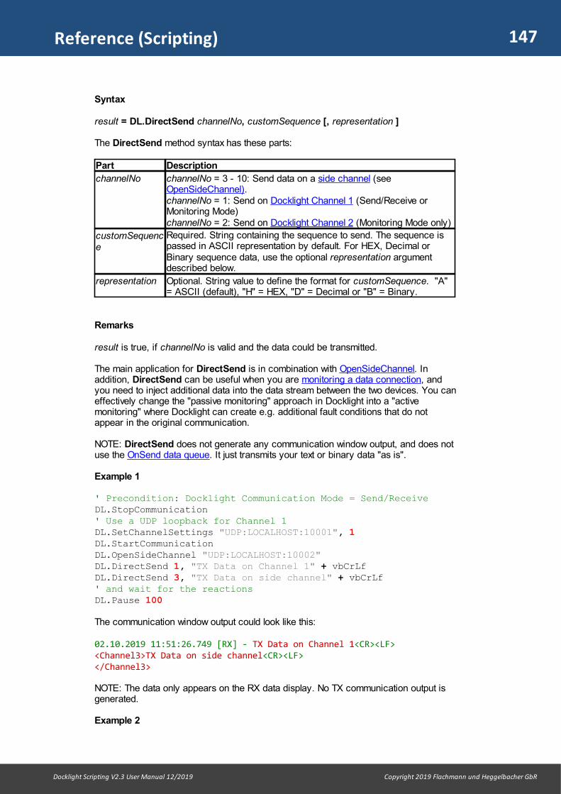
147
Docklight Scripting V2.3 User Manual 12/2019 Copyright 2019 Flachmann und Heggelbacher GbR
Reference (Scripting)
Syntax
result = DL.DirectSend channelNo, customSequence [, representation ]
The DirectSend method syntax has these parts:
Part Description
channelNo channelNo = 3 - 10: Send data on a side channel (seeOpenSideChannel).channelNo = 1: Send on Docklight Channel 1 (Send/Receive orMonitoring Mode) channelNo = 2: Send on Docklight Channel 2 (Monitoring Mode only)
customSequence
Required. String containing the sequence to send. The sequence ispassed in ASCII representation by default. For HEX, Decimal orBinary sequence data, use the optional representation argumentdescribed below.
representation Optional. String value to define the format for customSequence. "A"= ASCII (default), "H" = HEX, "D" = Decimal or "B" = Binary.
Remarks
result is true, if channelNo is valid and the data could be transmitted.
The main application for DirectSend is in combination with OpenSideChannel. Inaddition, DirectSend can be useful when you are monitoring a data connection, andyou need to inject additional data into the data stream between the two devices. You caneffectively change the "passive monitoring" approach in Docklight into a "activemonitoring" where Docklight can create e.g. additional fault conditions that do notappear in the original communication.
NOTE: DirectSend does not generate any communication window output, and does notuse the OnSend data queue. It just transmits your text or binary data "as is".
Example 1
' Precondition: Docklight Communication Mode = Send/ReceiveDL.StopCommunication' Use a UDP loopback for Channel 1DL.SetChannelSettings "UDP:LOCALHOST:10001", 1DL.StartCommunicationDL.OpenSideChannel "UDP:LOCALHOST:10002"DL.DirectSend 1, "TX Data on Channel 1" + vbCrLfDL.DirectSend 3, "TX Data on side channel" + vbCrLf' and wait for the reactionsDL.Pause 100
The communication window output could look like this:
02.10.2019 11:51:26.749 [RX] - TX Data on Channel 1<CR><LF><Channel3>TX Data on side channel<CR><LF></Channel3>
NOTE: The data only appears on the RX data display. No TX communication output isgenerated.
Example 2

148
Docklight Scripting V2.3 User Manual 12/2019 Copyright 2019 Flachmann und Heggelbacher GbR
Reference (Scripting)
' Precondition: Docklight Communication Mode = MonitoringDL.StopCommunicationDL.SetChannelSettings "UDP:LOCALHOST:10001", 1DL.SetChannelSettings "UDP:LOCALHOST:10002", 2DL.StartCommunicationDL.DirectSend 2, "Bounce"' and let this go on for a whileDL.Pause 1000
The communication window output could look like this:
02.10.2019 12:03:08.840 [UDP:LOCALHOST:10002] - Bounce02.10.2019 12:03:08.840 [UDP:LOCALHOST:10001] - Bounce02.10.2019 12:03:08.841 [UDP:LOCALHOST:10002] - Bounce02.10.2019 12:03:08.848 [UDP:LOCALHOST:10001] - Bounce02.10.2019 12:03:08.851 [UDP:LOCALHOST:10002] - Bounce02.10.2019 12:03:08.864 [UDP:LOCALHOST:10001] - Bounce
NOTE: The data is repeatedly reflected between Channel 1 and Channel 2, because weuse UDP loopbacks on both ends, and Docklight Monitoring Mode uses DataForwarding by default.
10.6 Debug Object / Script Debugging
Docklight Scripting offers additional debugging features through the Debug object.
Method / Property Description
Debug.Mode = newValue Sets the script debug mode:newValue = 0: No Debugging, all Debug methods areignored.newValue = 1: Debug Mode. The Debug methodsdescribed below are executed.
Debug.AssertassertCondition
Breaks the script execution, if assertCondition is False.The script execution can be continued manually using
the Continue Script toolbar.
Debug.Break Breaks the script execution unconditionally.
Debug.PrintMsg debugMsg Adds an additional debug text to the communicationwindow display, including a date/time stamp and thecurrent line of script code.
Remarks
The PrintMsg and Assert methods are very useful to print and watch variable values atvarious points of execution.
For the Debug methods to have any effect, you need to enable Debug Mode first bysetting the Mode property to one:Debug.Mode = 1
Example
' Example Debug object
Debug.Mode = 1
Count = 0

149
Docklight Scripting V2.3 User Manual 12/2019 Copyright 2019 Flachmann und Heggelbacher GbR
Reference (Scripting)
Do Count = Count + 1 ' print some debug information: the value of the countvariable Debug.PrintMsg "count = " & count ' break script execution when reaching 5 Debug.Assert (Count <> 5)Loop Until Count = 10
' now the same thing with debug mode 'off' - Debug methods haveno effect
Debug.Mode = 0Debug.PrintMsg "this is never printed"Debug.Break ' this is never executed
DL.AddComment "Debug test ended"
After running this script, the communication window could look like this:
07.04.2009 15:45:06.078 line #9 Debug: count = 1
07.04.2009 15:45:06.100 line #9 Debug: count = 2
07.04.2009 15:45:06.119 line #9 Debug: count = 3
07.04.2009 15:45:06.131 line #9 Debug: count = 4
07.04.2009 15:45:06.145 line #9 Debug: count = 5
07.04.2009 15:45:06.158 line #11 Debug: Assert is False
(here the user manually continues using the Continue Script button)
07.04.2009 15:45:07.781 line #9 Debug: count = 6
07.04.2009 15:45:07.805 line #9 Debug: count = 7
07.04.2009 15:45:07.830 line #9 Debug: count = 8
07.04.2009 15:45:07.853 line #9 Debug: count = 9
07.04.2009 15:45:07.881 line #9 Debug: count = 10 Debug test ended
10.7 #include Directive
Instructs the Docklight script preprocessor to insert the contents of the specified file atthe point where the #include directive appears.
Syntax
#include filePathName
The #include syntax has these parts:
Part Description

150
Docklight Scripting V2.3 User Manual 12/2019 Copyright 2019 Flachmann und Heggelbacher GbR
Reference (Scripting)
filePathName Required. String containing the file path (directory and file name) ofthe Docklight script file (.pts file) to include. The file extension .pts canbe omitted. If no directory is specified, Docklight uses the current workingdirectory.
Remarks
If filePathName is not a valid Docklight script file or does not exist, Docklight reports anerror and the script is not started. The #include directive tells the preprocessor to treat the contents of a specified file as ifthose contents had appeared in the source program at the point where the directiveappears.
You can organize constant declarations and function definitions into include files andthen use #include directives to add these definitions to any script. Include files are alsouseful for incorporating declarations of external variables and complex data types.
Example
' Example #include directive' #include "myIncludeFile.pts"DL.AddComment " Pi = " & conPi
With myIncludeFile.pts containing the following definition:
Const conPi = 3.14159265358979
The resulting communication window output would look like this:
Pi = 3.14159265358979
10.8 Command Line Syntax
The Docklight Scripting application supports command line arguments to load (and run)predefined project or script files. Use the following command syntax:
Docklight_Scripting.exe [ -r ] [ -m ] [ -i ] [ projectPathName.ptp ][ scriptPathName.pts ]
The Docklight scripting command line has these parts:
Part Description
-r Optional argument, used in combination withscriptPathName.pts. Runs the script immediately. If no run-timeerror or user stop occurs, the Docklight Scripting application isclosed after the script execution ends.
-m Optional argument. Minimize the Docklight Scripting applicationwindow on startup.
-i Optional argument. Invisible operation / no main window. Usefulin combination with the -r option and scriptPathName.pts.
projectPathName.ptp Optional. Loads the Docklight project file projectPathName.ptp
scriptPathName.pts Optional. Loads the Docklight script file scriptPathName.pts
Remarks
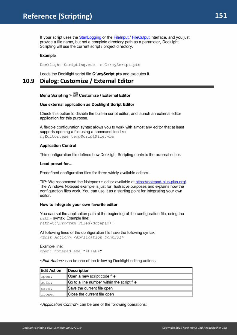
151
Docklight Scripting V2.3 User Manual 12/2019 Copyright 2019 Flachmann und Heggelbacher GbR
Reference (Scripting)
If your script uses the StartLogging or the FileInput / FileOutput interface, and you justprovide a file name, but not a complete directory path as a parameter, DocklightScripting will use the current script / project directory.
Example
Docklight_Scripting.exe -r C:\myScript.pts
Loads the Docklight script file C:\myScript.pts and executes it.
10.9 Dialog: Customize / External Editor
Menu Scripting > Customize / External Editor
Use external application as Docklight Script Editor
Check this option to disable the built-in script editor, and launch an external editorapplication for this purpose.
A flexible configuration syntax allows you to work with almost any editor that at leastsupports opening a file using a command line likemyEditor.exe tempScriptFile.vbs
Application Control
This configuration file defines how Docklight Scripting controls the external editor.
Load preset for...
Predefined configuration files for three widely available editors.
TIP: We recommend the Notepad++ editor available at https://notepad-plus-plus.org/.The Windows Notepad example is just for illustrative purposes and explains how theconfiguration files work. You can use it as a starting point for integrating your owneditor.
How to integrate your own favorite editor
You can set the application path at the beginning of the configuration file, using thepath= syntax. Example line: path=C:\Program Files\Notepad++
All following lines of the configuration file have the following syntax:<Edit Action> <Application Control>
Example line:open: notepad.exe "%FILE%"
<Edit Action> can be one of the following Docklight editing actions:
Edit Action Description
open: Open a new script code file
goto: Go to a line number within the script file
save: Save the current file open
close: Close the current file open
<Application Control> can be one of the following operations:

152
Docklight Scripting V2.3 User Manual 12/2019 Copyright 2019 Flachmann und Heggelbacher GbR
Reference (Scripting)
ApplicationControl
Description
sendkeys Send one or more keystrokes to the external editor. It uses the sameargument syntax as the Windows Script Host SendKeys method. Seethe related Microsoft documentation for details. Example:goto: sendkeys +^{HOME}{DOWN %LINE%}+{UP}
endtask End the external application. Example:close: endtask
activate Activate the external application window. Example:goto: activate
sleep Wait up to 500 milliseconds to give the external application some extratime to sort things out. This might be necessary when working with thesendkeys: operation described above. Example:open: sleep 100
CommandLine
Besides the above operations, you can execute any Windowscommand line, e.g. for launching your external editor. Example:open: notepad++.exe -nosession -lvb -n%LINE% "%FILE%"
For each <Edit Action> you can define several command lines, e.g.goto: sendkeys +^{HOME}{DOWN %LINE%}+{UP}goto: activate
The following wildcards are available for <Application Control>
Wildcard Description
%FILE% Path to a temporary file containing the script code to edit. DocklightScripting creates and manages the temporary file.
%FILE_UNIX%
Same as %FILE%, but uses a UNIX-style '/' for the path separator. Thisis useful for some open source editor packages that have problemswith the Windows backslash ('\') separator.
%FILE_ESC% Same as %FILE%, but uses a double backslash ('escape sequence')for the path separator. This is necessary e.g. when working with theSciTE free source code editor.
%LINE% The current source code line number. This is used for the goto:action.
Remarks
The External Editor Support is a flexible and open solution to our users who are workingwith large script projects and would prefer to work with a full-featured editing package.
The application control interface offered described above gives you flexibility, but weare aware of the limitations of controlling third-party applications that are not reallydesigned to be controlled from outside.
If you find a smart configuration file for your personal favorite editor, or you areexperiencing problems with the above interface, our Customer Support would be happyto hear about it.

Support
154
Docklight Scripting V2.3 User Manual 12/2019 Copyright 2019 Flachmann und Heggelbacher GbR
Support
11 Support
11.1 Web Support and Troubleshooting
For up-to-date FAQs and troubleshooting information, see our online support pagesavailable at
www.docklight.de/support/
For Docklight-related news and information about free maintenance updates, see:
www.docklight.de/news.htm
11.2 E-Mail Support
We provide individual e-mail support to our registered customers. Please include yourDocklight license key number in your request. We will contact you as soon as possibleto find a solution to your problem. Send your support request to
Appendix
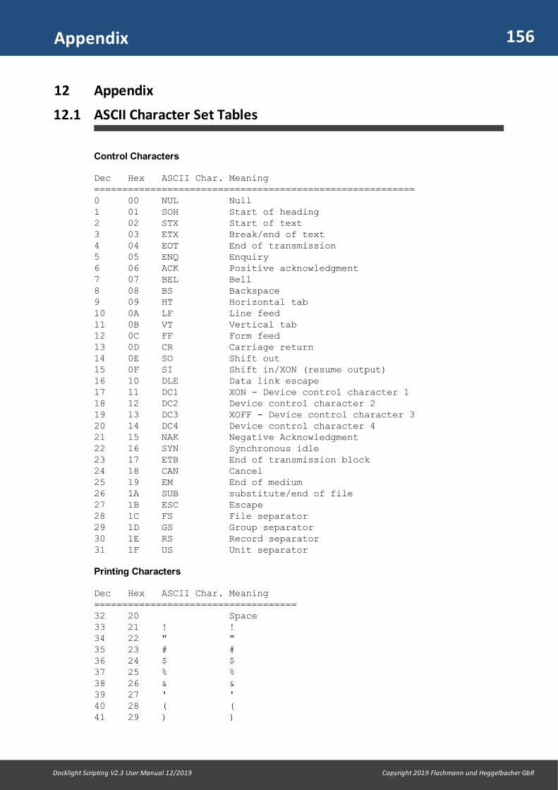
156
Docklight Scripting V2.3 User Manual 12/2019 Copyright 2019 Flachmann und Heggelbacher GbR
Appendix
12 Appendix
12.1 ASCII Character Set Tables
Control Characters
Dec Hex ASCII Char. Meaning =========================================================0 00 NUL Null 1 01 SOH Start of heading 2 02 STX Start of text 3 03 ETX Break/end of text 4 04 EOT End of transmission 5 05 ENQ Enquiry 6 06 ACK Positive acknowledgment 7 07 BEL Bell 8 08 BS Backspace 9 09 HT Horizontal tab 10 0A LF Line feed 11 0B VT Vertical tab 12 0C FF Form feed 13 0D CR Carriage return 14 0E SO Shift out 15 0F SI Shift in/XON (resume output) 16 10 DLE Data link escape 17 11 DC1 XON - Device control character 1 18 12 DC2 Device control character 2 19 13 DC3 XOFF - Device control character 3 20 14 DC4 Device control character 4 21 15 NAK Negative Acknowledgment 22 16 SYN Synchronous idle 23 17 ETB End of transmission block 24 18 CAN Cancel 25 19 EM End of medium 26 1A SUB substitute/end of file 27 1B ESC Escape 28 1C FS File separator 29 1D GS Group separator 30 1E RS Record separator 31 1F US Unit separator
Printing Characters
Dec Hex ASCII Char. Meaning ====================================32 20 Space 33 21 ! ! 34 22 " " 35 23 # # 36 24 $ $ 37 25 % % 38 26 & & 39 27 ' ' 40 28 ( ( 41 29 ) )

157
Docklight Scripting V2.3 User Manual 12/2019 Copyright 2019 Flachmann und Heggelbacher GbR
Appendix
42 2A * * 43 2B + + 44 2C , , 45 2D - - 46 2E . . 47 2F / / 48 30 0 Zero 49 31 1 One 50 32 2 Two 51 33 3 Three 52 34 4 Four 53 35 5 Five 54 36 6 Six 55 37 7 Seven 56 38 8 Eight 57 39 9 Nine 58 3A : : 59 3B ; ; 60 3C < < 61 3D = = 62 3E > > 63 3F ? ? 64 40 @ @ 65 41 A A 66 42 B B 67 43 C C 68 44 D D 69 45 E E 70 46 F F 71 47 G G 72 48 H H 73 49 I I 74 4A J J 75 4B K K 76 4C L L 77 4D M M 78 4E N N 79 4F O O 80 50 P P 81 51 Q Q 82 52 R R 83 53 S S 84 54 T T 85 55 U U 86 56 V V 87 57 W W 88 58 X X 89 59 Y Y 90 5A Z Z 91 5B [ [ 92 5C \ \ 93 5D ] ] 94 5E ^ ^ 95 5F _ _ 96 60 ` ` 97 61 a a 98 62 b b

158
Docklight Scripting V2.3 User Manual 12/2019 Copyright 2019 Flachmann und Heggelbacher GbR
Appendix
99 63 c c 100 64 d d 101 65 e e 102 66 f f 103 67 g g 104 68 h h 105 69 i i 106 6A j j 107 6B k k 108 6C l l 109 6D m m 110 6E n n 111 6F o o 112 70 p p 113 71 q q 114 72 r r 115 73 s s 116 74 t t 117 75 u u 118 76 v v 119 77 w w 120 78 x x 121 79 y y 122 7A z z 123 7B { { 124 7C | | 125 7D } } 126 7E ~ Tilde 127 7F DEL Delete
12.2 Hot Keys
General Hot Keys
Applies to· Communication Window (ASCII, HEX, Decimal, Binary)· Edit Send Sequence dialog / Edit Receive Sequence dialog· Documentation Area
Function Hot Key
Context-specific help F1
Cut Ctrl+X
Copy Ctrl+C
Paste Ctrl+V
Delete Del
Select all Ctrl+A
Context-specific Hot Keys
Docklight menu
Menu Function Hot Key
File New Project Ctrl+N
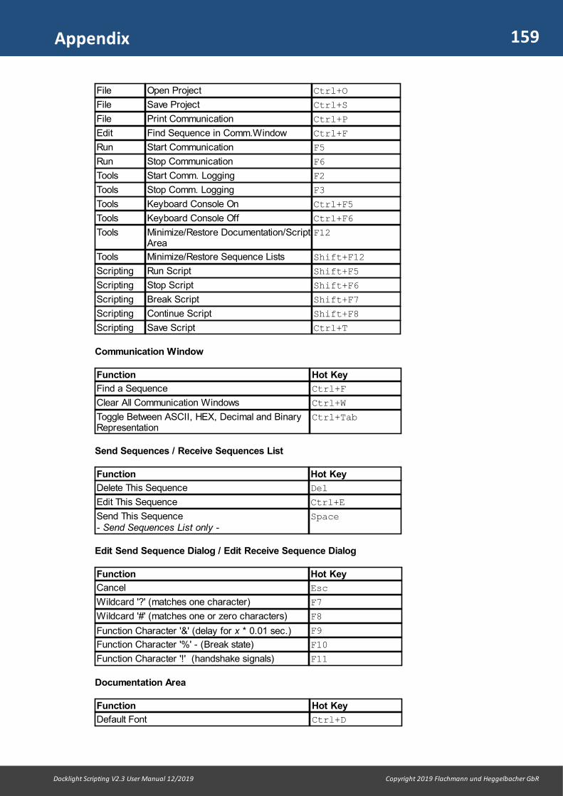
159
Docklight Scripting V2.3 User Manual 12/2019 Copyright 2019 Flachmann und Heggelbacher GbR
Appendix
File Open Project Ctrl+O
File Save Project Ctrl+S
File Print Communication Ctrl+P
Edit Find Sequence in Comm.Window Ctrl+F
Run Start Communication F5
Run Stop Communication F6
Tools Start Comm. Logging F2
Tools Stop Comm. Logging F3
Tools Keyboard Console On Ctrl+F5
Tools Keyboard Console Off Ctrl+F6
Tools Minimize/Restore Documentation/ScriptArea
F12
Tools Minimize/Restore Sequence Lists Shift+F12
Scripting Run Script Shift+F5
Scripting Stop Script Shift+F6
Scripting Break Script Shift+F7
Scripting Continue Script Shift+F8
Scripting Save Script Ctrl+T
Communication Window
Function Hot Key
Find a Sequence Ctrl+F
Clear All Communication Windows Ctrl+W
Toggle Between ASCII, HEX, Decimal and BinaryRepresentation
Ctrl+Tab
Send Sequences / Receive Sequences List
Function Hot Key
Delete This Sequence Del
Edit This Sequence Ctrl+E
Send This Sequence - Send Sequences List only -
Space
Edit Send Sequence Dialog / Edit Receive Sequence Dialog
Function Hot Key
Cancel Esc
Wildcard '?' (matches one character) F7
Wildcard '#' (matches one or zero characters) F8
Function Character '&' (delay for x * 0.01 sec.) F9
Function Character '%' - (Break state) F10
Function Character '!' (handshake signals) F11
Documentation Area
Function Hot Key
Default Font Ctrl+D

160
Docklight Scripting V2.3 User Manual 12/2019 Copyright 2019 Flachmann und Heggelbacher GbR
Appendix
12.3 RS232 Connectors / Pinout
The most common connectors for RS232 communication are
· 9-pole SUB D9 (EIA/TIA 574 standard). Introduced by IBM and widely used. Seebelow.
· 25-pole SUB D25 (RS232-C). This is the original connector introduced for theRS232 standard. It provides a secondary communication channel.
· 8-pole RJ45 (RS232-D, according to EIA/TIA-561 standard).
RS232 SUB D9 (D-Sub DB9) Pinout
View: Looking into the male connector.Pinout: From a DTE perspective (the DTE transmits data on the TX Transmit Data line,while the DCE receives data on this line)
Pin No. Signal Name Description DTE in/out
1 DCD Data Carrier Detect Input
2 RX Receive Data Input
3 TX Transmit Data Output
4 DTR Data Terminal Ready Output
5 SGND Signal Ground -
6 DSR Data Set Ready Input
7 RTS Request To Send Output
8 CTS Clear To Send Input
9 RI Ring Indicator Input
RS232 SUB D25 (D-Sub DB25) Pinout
View: DTE perspective, looking into the male connector
Pin No. Signal Name Description
1 - Protective/Shielding Ground
2 TX Transmit Data
3 RX Receive Data
4 RTS Request To Send
5 CTS Clear To Send
6 DSR Data Set Ready
7 SGND Signal Ground
8 DCD Data Carrier Detect
9 - Reserved
161
Docklight Scripting V2.3 User Manual 12/2019 Copyright 2019 Flachmann und Heggelbacher GbR
Appendix
10 - Reserved
11 - Unassigned
12 SDCD Secondary Data Carrier Detect
13 SCTS Secondary Clear To Send
14 STx Secondary Transmit Data
15 TxCLK Transmit Clock
16 SRx Secondary Receive Data
17 RxCLK Receive Clock
18 LL Local Loopback
19 SRTS Secondary Request To Send
20 DTR Data Terminal Ready
21 RL/SQ Remote Loopback / SignalQualify Detector
22 RI Ring Indicator
23 CH/CI Signal Rate Selector
24 ACLK Auxiliary Clock
25 - Unassigned
RS232-D, RJ45 pinout
Pin No. Signal Name Description
1 DSR / RI Data Set Ready / Ring Indicator
2 DCD Data Carrier Detect
3 DTR Data Terminal Ready
4 SGND Signal Ground
5 RX Receive Data
6 TX Transmit Data
7 CTS Clear To Send
8 RTS Request To Send
12.4 Standard RS232 Cables
RS232 Connections
When connecting two serial devices, different cable types must be used, depending onthe characteristics of the serial device and the type of communication used.
Overview of RS232 SUB D9 (D-Sub DB9) interconnections

162
Docklight Scripting V2.3 User Manual 12/2019 Copyright 2019 Flachmann und Heggelbacher GbR
Appendix
serial device 1 serial device 2 flow control(handshaking)
recommended cable
DTE (DataTerminalEquipment)
DTE no handshakesignals
simple null modem cable
DTE DTE DTE/DCEcompatiblehardware flowcontrol
null modem cable with partialhandshaking
DTE DCE (DataCommunicationsEquipment)
no handshakesignals
simple straight cable
DTE DCE hardware flowcontrol
full straight cable
DCE DCE no handshakesignals
simple null modem cable, but withSUB D9 male connectors on bothends
DCE DCE hardware flowcontrol
null modem cable with partialhandshaking but with SUB D9male connectors on both ends
SUB D9 Simple Straight Cable
Area of Application: DTE-DCE Communication where no additional handshake signalsare used.
SUB D9 Full Straight Cable
Area of Application: DTE-DCE Communication with hardware flow control usingadditional handshake signals.
SUB D9 Simple Null Modem Cable without Handshaking
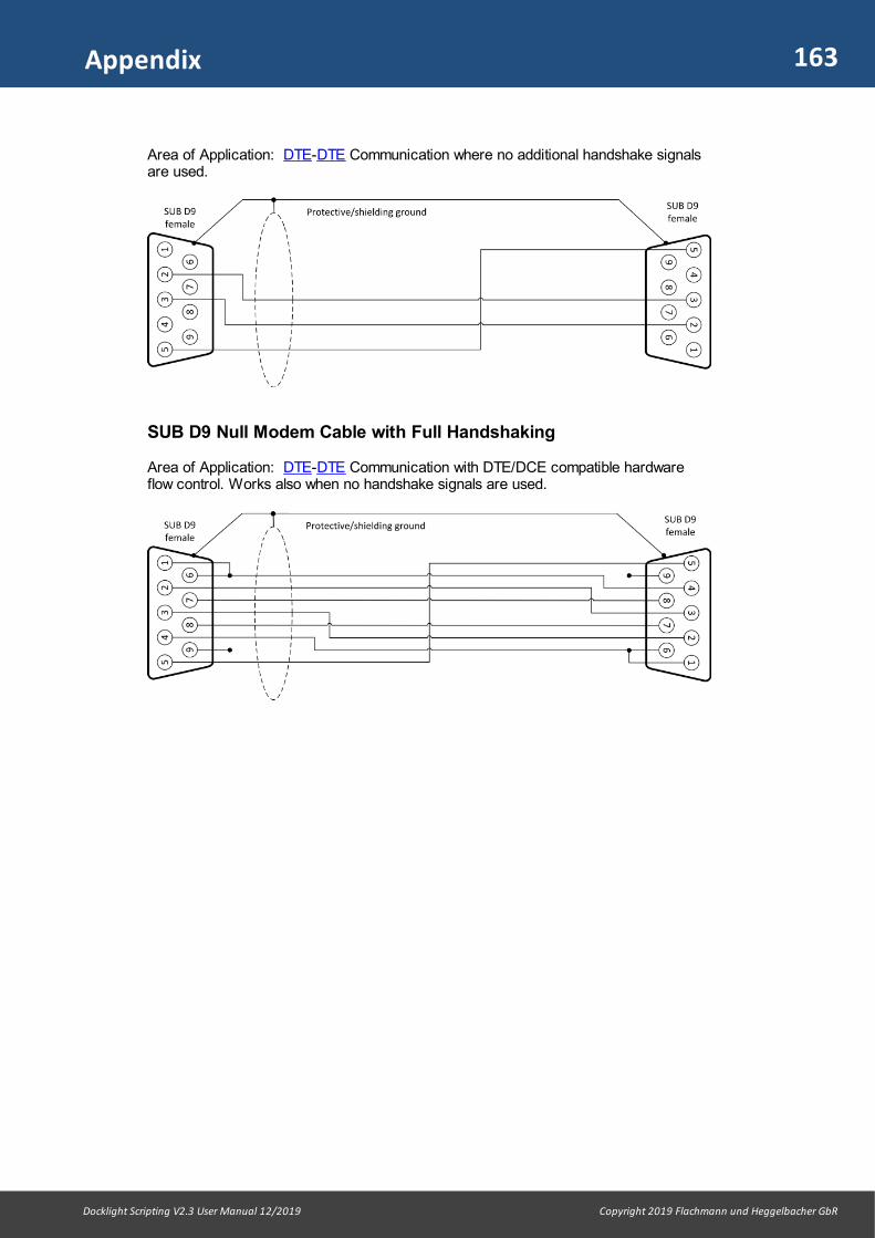
163
Docklight Scripting V2.3 User Manual 12/2019 Copyright 2019 Flachmann und Heggelbacher GbR
Appendix
Area of Application: DTE-DTE Communication where no additional handshake signalsare used.
SUB D9 Null Modem Cable with Full Handshaking
Area of Application: DTE-DTE Communication with DTE/DCE compatible hardwareflow control. Works also when no handshake signals are used.
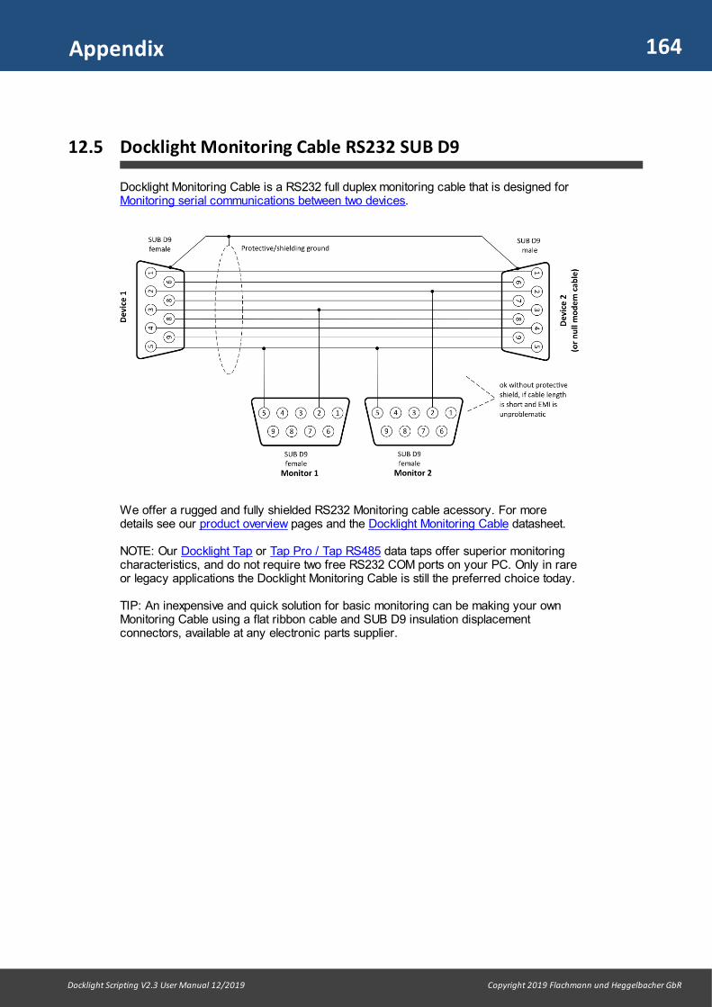
164
Docklight Scripting V2.3 User Manual 12/2019 Copyright 2019 Flachmann und Heggelbacher GbR
Appendix
12.5 Docklight Monitoring Cable RS232 SUB D9
Docklight Monitoring Cable is a RS232 full duplex monitoring cable that is designed forMonitoring serial communications between two devices.
We offer a rugged and fully shielded RS232 Monitoring cable acessory. For moredetails see our product overview pages and the Docklight Monitoring Cable datasheet.
NOTE: Our Docklight Tap or Tap Pro / Tap RS485 data taps offer superior monitoringcharacteristics, and do not require two free RS232 COM ports on your PC. Only in rareor legacy applications the Docklight Monitoring Cable is still the preferred choice today.
TIP: An inexpensive and quick solution for basic monitoring can be making your ownMonitoring Cable using a flat ribbon cable and SUB D9 insulation displacementconnectors, available at any electronic parts supplier.

165
Docklight Scripting V2.3 User Manual 12/2019 Copyright 2019 Flachmann und Heggelbacher GbR
Appendix
12.6 Docklight Tap
Docklight Tap is a full-duplex RS232 communications monitoring solution for the USBport.
Area of Application: Monitoring serial communications between two devices
Docklight has built-in support for the Docklight Tap. It recognizes the dual port USBserial converter and offers high-speed, low-latency access to the monitoring data. UseDocklight Monitoring Mode and Receive Channel settings TAP0 / TAP1. See theDocklight Project Settings and How to Obtain Best Timing Accuracy for details.
Please also see our product overview pages for more information about the DocklightTap.

166
Docklight Scripting V2.3 User Manual 12/2019 Copyright 2019 Flachmann und Heggelbacher GbR
Appendix
12.7 Docklight Tap Pro / Tap 485
Docklight Tap Pro and Docklight Tap 485 are advanced, high-resolution monitoringsolutions for the USB port. They allow true milliseconds time measurements andmonitoring high-speed data connections including RS232 status/handshake lines. Theyare supported by Docklight in a similar way as the Docklight Tap.
For Docklight Tap Pro and Tap 485 applications, use Docklight Monitoring Mode andReceive Channel settings VTP0 / VTP1. See the Docklight Project Settings for moredetails.
Please also see our product overview pages for more information about the DocklightTap Pro and Docklight Tap 485.
Docklight Tap Pro
Docklight Tap RS485
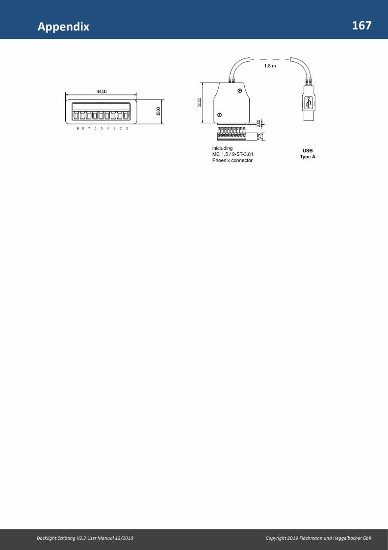
167
Docklight Scripting V2.3 User Manual 12/2019 Copyright 2019 Flachmann und Heggelbacher GbR
Appendix

Glossary / Terms Used

169
Docklight Scripting V2.3 User Manual 12/2019 Copyright 2019 Flachmann und Heggelbacher GbR
Glossary / Terms Used
13 Glossary / Terms Used
13.1 Action
For a Receive Sequence, the user may define an action that is performed afterreceiving the specified sequence. Possible actions are· Sending a Send Sequence
Only Send Sequences without any wildcards can be used· Inserting a comment
A user-defined text or an additional date/time stamp is added to the communicationdata window and log file
· Triggering a Snapshot· Stopping communication
13.2 Break
A break state on an RS232 connection is characterized by the TX line going to Space(logical 0) for a longer period than the maximum character frame length including startand stop bits. Some application protocols, e.g. LIN, use this for synchronizationpurposes.
13.3 Character
A character is the basic unit of information processed by Docklight. Docklight alwaysuses 8 bit characters. Nevertheless, the communication settings also allow datatransmission with 7 bits or less. In this case, only a subset of the 256 possible 8 bitcharacters will be used but the characters will still be stored and processed using an 8bit format.
13.4 CRC
Cyclic Redundancy Code. A CRC is a method to detect whether a receivedsequence/message has been corrupted, e.g. by transmission errors. This is done byconstructing an additional checksum value that is a function of the message's payloaddata, and then appending this value to the original message. The receiver calculates thechecksum from the received data and compares it to the transmitted CRC value to see ifthe message is unmodified. CRCs are commonly used because they allow the detectionof typical transmission errors (bit errors, burst errors) with very high accuracy.
CRC algorithms are based on polynomial arithmetic, and come in many differentversions. Common algorithms are CRC-CCITT, CRC-16 and CRC-32. An example of anapplication protocol that uses a CRC is Modbus over Serial Line.
A popular article about CRCs is "CRC Implementation Code in C" by Michael Barr,formerly published as "Slow and Steady Never Lost the Race" and "Easier Said ThanDone": https://barrgroup.com/Embedded-Systems/How-To/CRC-Calculation-C-Code
Docklight Scripting's CRC functionality (DL.CalcChecksum) was inspired by the abovearticle and the proposed Boost CRC library:http://www.boost.org/libs/crc/index.html
170
Docklight Scripting V2.3 User Manual 12/2019 Copyright 2019 Flachmann und Heggelbacher GbR
Glossary / Terms Used
Last not least, if you are truly fascinated by CRC alchemy, you will sooner or later runinto mentions of the following classic article from 1993: "A Painless Guide to CRC Error Detection Algorithms" by Ross N. Williams: http://ross.net/crc/crcpaper.html / http://ross.net/crc/download/crc_v3.txt
13.5 DCE
Data Communications Equipment. The terms DCE and DTE refer to the serial deviceson each side of an RS232 link. A modem is a typical example of a DCE device. DCEare normally equipped with a female SUB D9 or SUB D25 connector. See also DTE.
13.6 DTE
Data Terminal Equipment. The terms DCE and DTE refer to the serial devices on eachside of an RS232 link. A PC or a terminal are examples of a typical DTE device. DTEare commonly equipped with a male SUB D9 or SUB D25 connector. All pinoutspecifications are written from a DTE perspective. See also DCE.
13.7 Flow Control
Flow control provides a mechanism for suspending transmission while one device isbusy or for some reason cannot further communicate. The DTE and DCE must agreeon the flow control mechanism used for a communication session. There are two typesof flow control: hardware and software.
Hardware Flow ControlUses voltage signals on the RS232 status lines RTS / DTR (set by DTE) and CTS / DSR(set by DCE) to control the transmission and reception of data. See also RS232 pinout.
Software Flow ControlUses dedicated ASCII control characters (XON / XOFF) to control data transmission.Software flow control requires text-based communication data or other data that doesnot contain any XON or XOFF characters.
13.8 HID
HID (Human Interface Device) is a device class and API used for USB and Bluetoothdevices.
Docklight Scripting supports HID access via VID / PID (vendor ID / product ID) or thefull Windows USB device path. Docklight Scripting allows binary and text-oriented datatransfers via HID Input and Output Reports.
A common application (besides standard Windows keyboard/mouse integration) for theHID device class are Embedded Devices with a custom protocol for simple datatransfer, e.g. measurement gauges or sensors
TIP: For more information on accessing HID devices via Docklight Scripting, see alsoour online support resources at www.docklight.de/support/.
171
Docklight Scripting V2.3 User Manual 12/2019 Copyright 2019 Flachmann und Heggelbacher GbR
Glossary / Terms Used
13.9 LIN
Local Interconnect Network. A low cost serial communication bus targeted at distributedelectronic systems in vehicles, especially simple components like door motors, steeringwheel controls, climate sensors, etc. See also http://www.lin-subbus.org
13.10 Modbus
Modbus is an application layer messaging protocol that provides client/servercommunications between devices connected on different types of buses or networks. Itis commonly used as "Modbus over Serial Line" in RS422/485 networks, but can beimplemented using TCP over Ethernet as well ("Modbus TCP").
Two different serial transmission modes for Modbus are defined: "RTU mode" for 8 bitbinary transmissions, and "ASCII mode". "RTU mode" is the default mode that must beimplemented by all devices.
See www.modbus.org for a complete specification of the Modbus protocol.
13.11 Multidrop Bus (MDB)
Multidrop Bus (MDB) is a more exotic RS232/RS485 application, used for example invending machine controllers, which requires a 9 bit compliant UART. The 9th data bit isused for selecting between an ADDRESS and a DATA mode.
A way to monitor and simulate such communication links using standard 8-bit UARTs,i.e. standard RS232-to-USB converters, is to use temporary parity changes.
See also Wikipedia on MDB and the original MDB 3.0 specification for moreinformation and details.
13.12 Named Pipe
A Named Pipe is a shared-memory mechanism that can be used for communicationbetween two processes on a Windows PC.
Docklight Scripting can open a client connection to a Named Pipe server and send orreceive 8-bit ASCII or byte data.
For details on Named Pipes see the Windows Development Center.
13.13 Receive Sequence
A Receive Sequence is a sequence that can be detected by Docklight within theincoming serial data. A Receive Sequence is specified by1. an unique name (e.g. "Modem Answer OK"),2. a character sequence (e.g. "6F 6B 13 10" in HEX format),3. an action that is triggered when Docklight receives the defined sequence.

172
Docklight Scripting V2.3 User Manual 12/2019 Copyright 2019 Flachmann und Heggelbacher GbR
Glossary / Terms Used
13.14 RS232
The RS232 standard is defined by the EIA/TIA (Electronic Industries Alliance /Telecommunications Industry Associations). The standard defines an asynchronousserial data transfer mechanism, as well as the physical and electrical characteristics ofthe interface.
RS232 uses serial bit streams transmitted at a predefined baud rate. The information isseparated into characters of 5 to 8 bits lengths. Additional start and stop bits are usedfor synchronization, and a parity bit may be included to provide a simple error detectionmechanism.
The electrical interface includes unbalanced line drivers, i.e. all signals are representedby a voltage with reference to a common signal ground. RS232 defines two states forthe data signals: mark state (or logical 1) and space state (or logical 0). The range ofvoltages for representing these states is specified as follows:
Signal State Transmitter VoltageRange
Receiver VoltageRange
Mark (logical 1) -15V to -5V -25V to -3V
Space (logical 0) +5V to +15V +3V to +25V
Undefined -5V to +5V -3V to +3V
The physical characteristics of the RS232 standard are described in the section RS232Connectors / Pinout
13.15 RS422
An RS422 communication link is a four-wire link with balanced line drivers. In abalanced differential system, one signal is transmitted using two wires (A and B). Thesignal state is represented by the voltage across the two wires. Although a commonsignal ground connection is necessary, it is not used to determine the signal state at thereceiver. This results in a high immunity against EMI (electromagnetic interference) andallows cable lengths of over 1000m, depending on the cable type and baud rate.
The EIA Standard RS422-A "Electrical characteristics of balanced voltage digitalinterface circuits" defines the characteristics of an RS422 interface.
Transmitter and receiver characteristics according to RS422-A are:
Signal State Transmitter DifferentialVoltage VAB
Receiver Differential VoltageVAB
Mark (or logical 1) -6V to -2V -6V to -200mV
Space (or logical 0) +2V to +6V +200mV to 6V
Undefined -2V to +2V -200mV to +200mV
Permitted Common Mode Voltage Vcm (mean voltage of A and B terminals withreference to signal ground): -7V to +7V
13.16 RS485
The RS485 standard defines a balanced two-wire transmission line, which may beshared as a bus line by up to 32 driver/receiver pairs. Many characteristics of the

173
Docklight Scripting V2.3 User Manual 12/2019 Copyright 2019 Flachmann und Heggelbacher GbR
Glossary / Terms Used
transmitters and receivers are the same as RS422. The main differences betweenRS422 and RS485 are· Two-wire (half duplex) transmission instead of four-wire transmission· Balanced line drivers with tristate capability. The RS485 line driver has an additional
"enable" signal which is used to connect and disconnect the driver to its outputterminal. The term "tristate" refers to the three different states possible at the outputterminal: mark (logical 1), space (logical 0) or "disconnected"
· Extended Common Mode Voltage (Vcm) range from -7V to +12V.
The EIA Standard RS485 "Standard for electrical characteristics of generators andreceivers for use in balanced digital multipoint systems" defines the characteristics ofan RS485 system.
13.17 Send Sequence
A Send Sequence is a sequence that can be sent by Docklight. A Send Sequence isspecified by1. an unique name (e.g. "Set modem speaker volume"),2. a character sequence (e.g. "41 54 4C 0D 0A" in HEX format).
There are two ways to make Docklight send a sequence:· Sending a sequence can be triggered manually by pressing the send button in the
Send Sequences list (see Main Window).
· Sending a sequence may be one possible reaction when Docklight detects a specificReceive Sequence within the incoming data (see Action).
13.18 Sequence
A sequence consists of one or more 8 bit characters. A sequence can be any part ofthe serial communications you are analyzing. It can consist of printable ASCIIcharacters, but may also include every non-printable character between 0 and 255decimal. Example: ATL2 (ASCII format)41 54 4C 0D 0A (HEX format)This sequence is a modem command to set the speaker volume on AT compatiblemodems. It includes a Carriage Return (0D) and a Line Feed (0A) character at the endof the line.
The maximum sequence size in Docklight is 1024 characters.
13.19 Sequence Index
The Sequence Index is the element number of a Send Sequence within the SendSequence List, or of a Receive Sequence within the Receive Sequence List. TheSequence Index is displayed in the upper left corner of the Edit Send Sequence or EditReceive Sequence dialog.
174
Docklight Scripting V2.3 User Manual 12/2019 Copyright 2019 Flachmann und Heggelbacher GbR
Glossary / Terms Used
13.20 Serial Device Server
A Serial Device Server is a network device that offers one or more serial COM ports(RS232, RS422/485) and transmits/receives the serial data over an Ethernet network.Serial Device Servers are a common way for upgrading existing devices that arecontrolled via serial port and make them "network-enabled".
13.21 Snapshot
Creating a snapshot in Docklight means generating a display of the serialcommunication shortly before and after a Trigger sequence has been detected. This isuseful when testing for a rare error which is characterized by a specific sequence. SeeCatching a specific sequence and taking a snapshot... for more information.
13.22 TCP
Transmission Control Protocol. TCP is, along with UDP, is the main transport-layerprotocol used in IP networks. TCP is connection-oriented - before two network hostscan communicate using TCP they must first establish a connection. TCP is a bytestream protocol that guarantees delivery. TCP ensures that data packets are transmittederror-free and in the right order, even if the underlying network is unreliable.
TCP uses port numbers 1-65535 to identify application end-points. Examples of well-known TCP applications and port numbers are FTP (21), TELNET (23), SMTP (25),HTTP (80) and POP3 (110).
13.23 Trigger
A Trigger is a Receive Sequence with the "Trigger" option enabled (see Dialog: EditReceive Sequence). When the Snapshot function is enabled, Docklight will not produceany output until a trigger sequence has been detected in the serial communication data.See Catching a specific sequence and taking a snapshot... for more information.
13.24 UART
Universal Asynchronous Receiver / Transmitter. The UART is the hardware componentthat performs the main serial communications tasks: - converting characters into a serial bit stream - adding start / stop / parity bits, and checking for parity errors on the receiver side- all tasks related to timing, baud rates and synchronization
Common UARTs are compatible with the 16550A UART. They include a 16 byte bufferfor incoming data (RX FiFo), and a 16 byte buffer for outgoing data (TX FiFo). Usuallythese buffers can be disabled/enabled using the Windows Device Manager andopening the property page for the appropriate COM port (e.g. COM1).
13.25 UDP
User Datagram Protocol. UDP is a transport-layer protocol used in IP networks. UDP isa connectionless protocol - the communication partners do not establish a connectionbefore transmitting data. UDP does not provide reliable or in-order transmissions.
175
Docklight Scripting V2.3 User Manual 12/2019 Copyright 2019 Flachmann und Heggelbacher GbR
Glossary / Terms Used
Datagrams can arrive out of order, arrive duplicated, or go missing during transmission.Applications requiring ordered reliable delivery of streams of data should instead useTCP.
UDP is faster than TCP and has advantages for many lightweight or timing-criticalnetwork applications. UDP is used for the Domain Name System on the Internet, forstreaming media applications like Voice Over IP, and for broadcasting in IP networks.
UDP uses port numbers 1-65535 to identify application end-points. Examples of well-known UDP services and port numbers are DNS (53), TIME (37), and SNMP (161 and162).
13.26 Virtual Null Modem
A virtual null modem is a PC software driver which emulates two serial COM ports thatare connected by a null modem cable. If one PC application sends data on one virtualCOM port, a second PC application can receive this data on the second virtual COMport and vice versa.
By using a virtual null modem driver on your PC you can easily debug and simulateserial data connections without the use of real RS232 ports and cables.
Virtual COM connections do not give you the same timing as real RS232 connectionsand usually do not emulate the actual bit-by-bit transmission using a predefined baudrate. Any data packet sent on the first COM port will appear in the second COM port'sreceive buffer almost immediately. For most debugging and simulation purposes thislimitation can be easily tolerated. Some virtual null modem drivers offer an additionalbaud rate emulation mode, where the data transfer is delayed to emulate a real RS232connection and its limited transmission rate.
For an Open Source Windows software that has been successfully tested withDocklight, see https://sourceforge.net/projects/com0com/We recommend the com0com v3.0.0.0 signed x64 and x32 versions, which wefrequently use on Windows 10 and Window 7:https://sourceforge.net/projects/com0com/files/com0com/3.0.0.0/com0com-3.0.0.0-i386-and-x64-signed.zip/download
13.27 Wildcard
A wildcard is a special character that serves as a placeholder within a sequence. It maybe used for Receive Sequences when parts of the received data are unspecified, e.g.measurement readings reported by a serial device. Wildcards can also be used tosupport parameters in a Send Sequence.
The following types of wildcards are available in Docklight:Wildcard '?' (F7): Matches exactly one arbitrary character (any ASCII code between 0and 255)Wildcard '#' (F8): Matches zero or one character. This is useful for supporting variablelength command arguments (e.g. a status word) in Send / Receive Sequences. SeeChecking for sequences with random characters or Sending commands withparameters for examples and additional information.Other placeholders that allow random data:

176
Docklight Scripting V2.3 User Manual 12/2019 Copyright 2019 Flachmann und Heggelbacher GbR
Glossary / Terms Used
Function Character '!' (F12): Bitwise comparison. This is useful if there are one orseveral bits within a character which should be tested for a certain value. See Functioncharacter ' ' (F12) - bitwise comparisons for details and an example.