doctn4ettr resume vt 018 697 author green, … · and materials lists, and student worksheets....
TRANSCRIPT

Doctn4Ettr RESUME
ED 072.244 VT 018 697
AUTHOR Green, CharlesTITLE Strength of Materials--Machinists.INSTITUTION Middlesex County Vocational and Technical High
Schools, New Brunswick, N.J.; New Jersey State Dept.of Education, Trenton..Div. of Vocational Education.;Rutgers, The State Univ., New Brunswick, N.J.Curriculum Lab.
PUB DATE Jul 71NOTE 252p.AVAILABLE FROM New Jersey Voc-Tech Curriculum Lab., Rutgers
University, Building 4103, Kilmer Campus, NewBrunswick, N.J. 08903 ($2.50)
EDRS PRICE MF-$0.65 HC Not Available from EDRS.DESCRIPTORS Achievement Tests; Glossaries; Industrial Arts;
*Manuals; Manufacturing; *Metals; QuestioningTechniques; Resource Materials; Secondary Grades;*Shop Curriculum; *Textbooks; *Trade and IndustrialEducation; Visual Aids; Vocational Development;Vocational Education
IDENTIFIERS Beginning Competence; *New Jersey
ABSTRACTIntended for use in a 1-year curriculum in an area
vocational.high school, this student manual for machine shop workwith industrial metals contains 17 instructional units, each with abehavioral objective, related information, shop procedures, equipmentand materials lists, and student worksheets. Developed by a regionalgroup of teachers and supervisors and tested in four vocationalschools, this text was prepared. by the chairman of the draftingdepartment at an area vocational high school..A course rationale,supplies list, a glossary, reference lists, and student achievementtests are included. Working diagrams and other visual aids illustratethe text. (AG)

MEMORANDUM Revised 5/69
TO: The ERIC Clearinghouse on Vocational and Technical EducationThe Ohio State University1900 Kenny RoadColumbus, Ohio 43210
FROM: (Person) Benjamin Shapiro, Director (Agency) N.J. Voc-Tech Curriculum Lab
(Address)Building 4103 - Kilmer Campus, New Brunswick, N.J. 08903
PATE: December 5, 1972
RE: (Author, Title, Publisher, Date) Mr. Charles Green, STRENGTH OF MATERIALS-
MACHINISTS,; N.J. Voc-Tech Curriculum Lab., Third Printing July 1971
Supplementary Inforiation on Instructional Material
Provide information below which is not included in the publication. Mark N/A ineach blank for which information is not available or not applicable. Mark Pwhen information is included in the publication. See reverse side for furtherinstructions.
(1) Source of Available Copies:Agency N.J. Voc-Tech Curriculum Laboratory, Rutgers UniversityAddressBuilding 410 - Kilmer Campus, New Brunswick, New Jersey 08903
Limitation on Available Copies NONE Price/Unit $2.50(quantity prices)
(2) Means Used to Develop Material:Development Group Teachers and supervisorsLevel of Group Regional
Method of Design, Testing, and Trial tested in 4 vocational schools
(3) Utilization of Material:Appropriate Educational Setting Area vocational hitischoelType of ProgramOccupational FocusGeographic AdaptabilityUses of MaterialUsers of Material
relatedoccupational cluster in metalsno limitsstudent usestudents
(4) Requirements for Using Material:Teacher Competency science certificationStudent or Trainee Selection Criteria
those in vocational fields to which this material would be a SI ro riateTime Allotment one year
Supplemental Media --Necessary
(Check Which)Desirable
Describe
Source (agency(address)
STATE OF NEW JERSEYDEPARTMENT OF EDUCATIONDIVISION OF VOCATIONAL EDUCATION
STRENGTH OF MATERIALS - MACHINISTS
CHARLES, GREEN - SUPERINTENDENTWARREN COUNTY TECHNICAL HIGH SCHOOLWASHINGTON; NEW JERSEY

State of New JerseyDepartment of EducationDivision of Vocational Education
U.S. DEPARTMENT OF HEALTH.EDUCATION & WELFAREOFFICE DF EDUCATION
THIS DOCUMENT HAS BEEN REPRO.DUCED EXACTLY AS RECEIVED FROMTHE PERSON OR ORGANIZATION ORIG.INATING IT. POINTS OF VIEW OR OPIN.IONS STATED DO NOT NECESSARILYREPRESENT OFFICIAL OFFICE OF EDU-CATION POSITION OR POLICY
STRENGTH OF MATERIALS -MACHINISTS1
Prepared byCharles Green Chairman, Drafting Department*Middlesex County Vocational and Technical High SchoolsNew Brunswick, New Jersey
Burr D. Coe Director
Vocational-TechnicalCurriculum LaboratoryRutgers The State UniversityBuilding 4103 Kilmer CampusNew Brunswick, New Jersey
*Now Superintendent of Warren County Technical High School
Third Printing, July 1971
1

DIVISION OF VOCATIONAL EDUCATIONROBERT M. WORTHINGTON, ASSISTANT COMMISSIONER
CURRICULUM LABORATORYRUTGERS - THE STATE UNIVERSITYBUILDING 4103 - KILMER CAMPUS
NEW BRUNSWICK, NEW JERSEY

STRENGTH OF MATERIALS FOR MACHINISTS
TABLE OF CONTENTS
Page
Introduction 1
General Form To Be Used For Writing Job Sheets 3
UNIT I INDUSTRIAL MATERIALSiron and Steel 4
Iron and Steel (Experiment) 7
Non-Ferrous Metals 10Non-Ferrous Metals (Experiment) 13
Abrasives 14Plastics 20Rubber 23
UNIT II THE PRODUCTION OF IRON AND STEELBlast Furnace Raw Materials 25
Blast Furnace 29
Puddling Furnace 33
Bessemer Process 36
Open-Hearth Furnace 38
Crucible Steel 41
Electric Furnace Steel 43
UNIT III PRODUCTION OF NON-FERROUS METALSAluminum 46
Copper 49Lead, Tin, Zinc 53
Cadmium 56
Magnesium 58Nickel 60Additional Non-Ferrous Metals 62
UNIT IV GENERAL PHYSICAL PROPERTIESIndustrial Materials 65
Strength 67
Hardness 63Weight and Density 69
Expansion 72

Page
UNIT V MECHANICAL PROPERTIES OF MATERIALSElasticity and Toughness 73
Ductility and High Temperature Strength .... . 76
Stiffness 78
Hardness 80
Malleability 82Resilience and Impact Strength 84
Corrosion Resistance 86
UNIT VI THE PLAIN CARBON STEELCarbon Steel Structure 88Carbon Content 91
Classification 94
UNIT VII THE CONTROL OF PHYSICAL PROPERTIES OF METALSHeat-Treating of Steel 97Warping and Cracking 99
Heat Treating Processes 101
Surface Treatments 103Heat Treating of Non-Ferrous Metals 105
UNIT VIII THE ALLOY STEELSDefinition and Types 108Classification 110Color Code 113Alloying Elements and Their Use 116
Alloying Effects 118
UNIT IX THE PRODUCTION OF CASTINGSClassification of Casting Procedures 120Melting Metais for Casting 122Patterns 125Sand Casting 127Metal Molding 130Die Casting 132Centrifugal Casting 134Defects in Castings 136
UNIT X NON-FERROUS ALLOYSCopper 139Aluminum 145Magnesium 148Aluminum and Magnesium 151Nickel 152Solders and Brazing 153Bearing Metals 154

1
PageUNIT XI THE STRUCTURE OF METALS
Crystals and Their Formation 156Grain Structure 159Deformation of Metals 160
UNIT XII SIMPLE STRESSUnit Stress Unit Strain 162Tension 165Compression 167Shear 169Bending and Twisting 171Ultimate Strength and Elastic Limit 173Factor of Safety 176
UNIT XIII BEARINGSFriction 178Lubrication 180Types 182
UNIT XIV FASTENERSScrew Threads 187Nuts, Screws, and Bolts Strength Requirements 191Nuts, Screws, and Bolts Threaded Length 195Set Screws ! 198Eye Bolts 201Rivets 203Keys and Splines 205Tapers and Taper Pins 207
UNIT XV SHAPING AND FORMING METALSHot Working 209Cold Working 212
UNIT XVI WELDINGDefinitions 215Oxyacetylene 217Arc 220
UNIT XVII MECHANICAL TESTING OF METALSTesting Laboratory 222
GLOSSARY 223
FORMULAS AND REFERENCES 228
ACHIEVEMENT TESTS

STRENGTH OF MATERIALS FOR MACHINISTS
INTRODUCTION
PURPOSE OF THE COURSE
A certain amount of machine shop work consists of the solution of physicalproblems beyond the everyday running, of machines. These problems usually involveprinciples of strength of materials. The application of these principles may be simple orcomplex. The great majority of the complex ones are handled by the engineeringdepartment. The machinist may be called in to lend his knowledge when needed. It isessential, though, that a prospective machinist should be introduced to problems, typicalmethods of arriving at a solution, and acceptable standards of presenting this data.
To teach typical methods of working a problem in detail would be a difficulttask and not necessary for the machinist. A simple outline that would be agreeable to atradesman is a general one. This outline would follow a method of solution that wouldattempt to explain:
1. An understanding of the required problem.
2. The assembling of observed data.
3. The setting up of an objective which will let the machinist progress to the result.
4. The use of some means or method to check the result or results.
The problems which the machinist runs up against are of varying types anddegrees of difficulty. In science, you solved problems that could be done by simplereasoning through previous experiences. In physics, more complex problems andexperiments were undertaken to give you a background in physical principles. In Strength ofMaterials, you will experience problems and gain knowledge that will help you in yourfuture work as a machinist.
In all cases, the machinist should never forget that not only is he solving fora result, but also for the record. In commercial practice the reports are filed for futurereference, either by the machine shop or engineering departments. Make the recordscomplete and easy to read to save time and money.
Because there is no excuse for a great difference in standards ofperformance, the student should learn the importance of doing a job properly the firsttime. To work a problem in a careless manner and then copy a careful, neat paper topresent as the finished job, is a waste of time. Any careless habits you Acqvire as a studentare likely to show up as work that cannot be accepted in the future.
1

By demanding a good quality of work in this course, we expect that goodperformance standards will be used, as well as the starting of satisfactory work habits.
The appearance of the work is one of the ways of showing how reliable it is.
MATERIALS AND SUPPLIES
The material needed tr., satisfy the requirements of the course follow:
A. Books1. This manual
2. References and other materials suggested by the instructor.
3. Any science or physics texts that you may find useful.
4. Do not be limited by these references. There are others.
B. Paper
1. Ruled white or plain white
C. Pencil with eraser
1. Well-pointed for clear notes
D. Drawing equipment
1. Compass
2. Protractor
3. Ruler
E. Folders
1. One as a file for the unfinished work.
2. Another as a file for the finished or graded work.
2

GENERAL FORM TO BE USED FOR WRITING OF JOB SHEETS
Shop Student's Name
Class Job Sheet No
STRENGTH OF MATERIALS
Objective
Sketch (Omit if none needed)
Results
Conclusions
Answers to questions or problems (if any are asked)
3

INDUSTRIAL MATERIALS
IRON AND STEEL
Strength of Materials Machinists Unit I Information Sheet No.1
OBJECTIVE:To learn what is meant by ferrous metals and how they are produced.
RELATED INFORMATION:Up to recent times, the terms iron and steel have been loosely titled ferrous
metals. A great advance in the science of metals has been the study of differences in ironand steel. The term iron and its chemical symbol (Fe, ferrous) is used when speaking of theelement iron, Mk:* ) steel, a combination of iron and carbon in varying degrees, is spoken ofas an alloy. A very soft. steel used in the manufacture of wire has 0.05 to 0.12 percentcarbon and a hard and strong steel used for tools and machinery has a range of 1.25 to 1.40percent carbon. The question is, how do we obtain these metals?
First, the iron ore is mined. Three-fourths of the iron ore for use in theUnited States is secured in the Lake Superior region.
Vertical Section of Iron Blast Furnace
FIG. 1 BLAST FURNACE
4

Secondly. the ore is transported by boat or train to the nearest blast furnace(Fig. 1) where the iron is extracted and cast into pigs, or else taken to the steel-makingfurnaces in a molten state. The pig.. are remelted for use in casting iron for machinery parts,or used cold in a puddling furnace to produce wrought iron. Wrought iron is valuablebecause of its ability to resist corrosion and fatigue failure. Also, since it is soft and ductile,wrought iron finds common usage in the manufacture of bolts, pipe, tubing, nails, etc.
The steel-making furnaces are theBessemer Convei ter (Fig. 2) or the open-hearthfurnace (Fig. 3). The Bessemer process produces anacid steel because of its refractory lining of silica. Thesteel produced is used mainly for wire, pipe, andscrew stock.
The typical open-hearth produces abasic steel because of the lining of dolomite ormagnesite and is used mainly for structural, spring,welding, boiler and sheet steels.
High grade tool steels and some alloysteels are made by the crucible process or by theelectric furnace process.
FIG. 3CROSS-SECTION OF ANOPEN-HEARTH FURNACE
5
FIG. 2CROSS-SECTION OF ABESSEMER CONVERTER

IRON AND STEEL
SHOP NAME
CLASS INFORMATION SHEET NO. 1-1
QUESTIONS
1. What is the chemical symbol for iron?
2. Name the steel-making furnaces.a.b.
c.d.
3. What types of steel does each produce?a.b.c.
d.
4. Give the percentage of carbon in a very soft steel.
5. Why is a blast furnace used?
6. Why is wrought iron valuable?
7. Give some uses of steel:a. With a high carbon content
1.
2.
b. Produced by the open-hearth process1. 4.
2. 5.
3.
c. Produced in the Bessemer converter1.
2.
3.
6

INDUSTRIAL MATERIALS
IRON AND STEEL
Strength of Materials Machinist Unit I Job Sheet No. 1
OBJECTIVE:
WANTED:
To learn how to test iron or steel.
Methods of testing materials to see if they are iron or steel.
RELATED INFORMATION:Many times in the course of replacing a part on a machine, the data relative
to the material of the part is unknown. By remembering these several methods to test a partfor its metallic content, you will save the company you are working for many hours oflabor.
Metal
0 iirc....... Sparks
m i
(A)
GrindingWheel
Metal Magnet
(C)
Hammer
Drill
1=1.........
(D)
Metal
MATERIALS:Pieces of cast iron, wrought iron, soft and hard steels, tool steel, grindingwheel, hammer, magnet and drill press.
PROCEDURE:(These tests should be made in the machine shop. Writing of experimentswill be completed in class.)
1. Take a sheet of paper to note the results of each step.
7

2. Take each metal and note sparks when testing as in Fig. A. Record what you observe.
3. Take each metal and see if it will resist or break from a blow of a hammer as shown inFig. B. Do the metals have the same ring when struck with the hammer? Record yourresults.
4. Take each metal and see if the metal is attracted to the magnet. (See Fig. C.) Put onyour paper the results of the test.
5. Take each metal and drill into it. (See Fig. D). Note the chip from drilling. Recordyour results. Keep chip samples for mounting on wood or cardboard.
8

SHOP
CLASS
IRON AND STEEL
NAME
JOB SHEET NO. 1-1
QUESTIONS
1. Which is more fragile with regard to shock, cast iron or steel? Explain.
2. Explain why the various metals give off different spark pictures.
3. Make simple sketches of various spark tests.
9

INDUSTRIAL MATERIALS
NON-FERROUS METALS
Strength of Materials Machinists Unit I Information Sheet No. 2
OBJECTIVE:To learn how non-ferrous metals are named and how they are produ-ed.
RELATED INFORMATION:You, living in a metal age, should get some idea of the size of the metal
industry. Check the yearly production of all metals from their ores in an almanac or someother suitable reference to see these figures. You will find the value of these metals is great.
Since iron and its alloys account for around 90 percent of the tonnage ofmetals produced, it is placed in one group, while the remaining metals are classed asnon-ferrous. Some of the more important ones are copper, lead, zinc, tin, nickel, aluminum,magnesium and cadmium.
The great majority of the non-ferrous metals can be used in the pure state oras the principal part of an alloy. Some are used as minor parts of alloys, while mixtures ofthe non-ferrous metals result in extremely important alloys.
Each of the metals has its own production methods, which will be brieflysketched.
Most of the aluminum exists in the outer layer of the earth. It is mined as acommercial ore and refined into aluminum. The larger quantity of aluminum is used in themanufacture of furniture, airplanes, railroad and trolley cars, automobiles, electric cablesand bus bars, conduits, rivets, kitchen utensils, tubes of pastes, siding and roofing, jar caps,etc.
Copper, one of the most widely distributed metals, is mined for smelting infurnaces. Because of the bad effect of impurities on the electrical conductivity of copper,the metal must go through a refining process. The largest proportion of copper produced isused in the electrical industry, while the remainder finds uses in copper alloys or otherpurposes where corrosion resistance with some strength and easy shaping is essential.
Lead is mined in nearly every count:.) . The deposits of ore are found to be amixture of lead and zinc in varying proportions. In practice, the reducing of lead ore iscomplex. Floatation, blast-furnace smelting, leaching and refining are steps in producingcommercial lead. Lead finds great use in chemical laboratories and plants as a lining becauseof its resistance to acids. Other applications are electric cable sheaths, gutters, storagebattery plates, and in the manufacture of paint products.
10

Zinc is extracted from ores by the electrolytic method. After refining, thezinc finds great use in galvanizing and some use as an alloy in the making of brass.
Tin is the only major metal of industrial use that is not found in greatquantities in the North American continent. It is mined chiefly in Malaysia. Indonesia, andBolivia. The ore has to be delivered to the smelting furnace in as pure a concentrate aspossible. After smelting, tin has to be refined for tin plating, solders, babbitt, and brass andbronze alloys. Approximately one-third of the tin used in the United States consists ofreclaimed tin. This system of recovering otherwise wasted tin for use in oxides, salts, andalloys, releases new tin for other purposes.
Cadmium, obtained commercially as a by-product in the processing of zincand sometimes lead, is probably the first metal that was not discovered in ore. Cadmium isbeing used as a substitute for tin in solder and in anti-friction alloys for bearings.
Magnesium is found on the earth's crust in great deposits which yield a goodamount for production. The metallic magnesium is prepared by refining. It is marketed inmany forms for ease in transporting to factories where it may be used to form sheets, wire,rods, tubes, or is alloyed with most metals.
In the core of the earth, plenty of nickel it is believed can be found. Canadaand Wales are chief producers of nickel ore for smelting and bessemerizing. Nickel has gooduse in Monel metal, which resists most acids. It is also used in other important ferrous andnon-ferrous alloys as a protective coating on iron or brass.
11

.... ....---7-...",--1C-T"...-------,...,..----.....-
NON-FERROUS METALS
SHOP NAME
CLASS INFORMATION SHEET NO. 1-2
QUESTIONS
1. Name eight non-ferrous metals.
a. c.
b. f.
c. g.
d. h.
2. Give a use for each of the non-ferrous metals you listed.
a. c.
b. f.
c. g.
d. h.
3. What is the percent of tonnage of production of non-ferrous metals when com-pared with all metals produced:
4. Which of the non-ferrous metals do you think is most important to us as a nation?Why?
12

INDUSTRIAL MATERIALS
NON-FERROUS METALS
Strength of Materials Machinists Unit I Job Sheet No. 2
OBJECTIVE:
WANTED:
SKETCH:
To learn some tests for recognizing non-ferrous metals.
Examples of tests of non-ferrous metals.
4trd,e 4)
A,' fie "'
el
MATERIALS:
Eye
C
Hammer
B
Samples of aluminum, copper, lead, and tinand zinc-coated materials, hammer.
PROCEDURE:
1. Observe the color of the various metals as shown in Fig. A. Record your observations.
2. Strike each metal a blow with the hammer as shown in Fig. B. Record on your paperhow soft or hard the metals are. Do any of them chip?
3. Expose the various materials to the weather, as shown in Fig. C, during a rainy andsunny period for one week. (Add water if no rainfall occurs for a couple of days).What happens to the various metals?
13

INDUSTRIAL MATERIALS
ABRASIVES
Strength of Materials Machinists Unit I Information Sheet No. 3
OBJECTIVE:To learn what is meant by'abrasives.
RELATED INFORMATION:Any substance that can be used to grind away the surface of another
substance is known as an abrasive. Abrasives are classed as either natural (sandstone) orartifical (silicon carbide, fused aluminum oxide, boron carbide, steel wool). Cutting,grinding and polishing operations can be performed on varying objects. To take care of thevarying hardnesses and toughnesses that the abrasive must face, different types and stylesmust be used.
1Diamond
The chart that follows shows the natural hard abrasives and their uses:
Crystals Dust
Wheeltruing,cutting,
andboring
Gempolish-
ing,
etc.
Coruftdum Emery Garnet,
Mr77oated Mfg. Coated. Loose Coate' d LooseWheels Papers Wheels Papers Grain Papers
and and andCloths Cloths
Semi-Cloths
GlassSome Si ag- finish- grind-metals ging Metals ing Hard- ing
metals and and woods,Some hard- polish- paintmetals wood ing andand wheels varnished
hard- surfaceswood
As you can notice, the diamond is used where great hardness is required incutting tools. Corundum is used also in a grain form for glass grinding. There are threegrades of emery, Grecian, Turkish, and American. The Grecian emery is hard and sharp andis used where grinding temperatures are high. Turkish emery is slightly softer and morebrittle than the Grecian material. It is used in glass grinding and polishing because of itstendency to break under pressure and form fresh, sharp-edged crystals. The Americanvariety which is much softer than the others finds its chief use on wood and soft metalwork. Garnet is used in between the sanding and rough polishing of plate glass.
14

When studying the various siliceous abrasives, remember that nearly all ofthem arc nearly pure silica. Quartz and flint arc examples of more or less silica. Smallsharpening stones for hand operation include sandstones, whetstones, hones and rubbingstones. Many stones that arc used in the United States arc made up of a mixture of naturalgrits bonded by clay, water and sodium silicate. After it is mixed, the material is molded andbaked. The grinding and polishing sands (pumice, tripoli, diatomite, pumicitc) are tough,sharp, hard sands free of clay.
The chart that follows gives the Siliceous Abrasives and their uses.
15

SIL
ICE
OU
S A
BR
ASI
VE
S
QU
AR
TZ
&SA
ND
STO
NE
PUM
ICE
VO
L A
N1C
FLIN
T&
SA
ND
DU
ST &
iPU
MIC
ITE
tir
giB
u1rr
Pebb
les
Smal
lC
rush
edB
lock
sL
oose
Ston
esSl
abs
coat
edI
Gra
inL
oose
II
pape
rR
ubbi
ngI
Gra
inG
rind
ing
InH
and
orPa
int
Gla
ssI
grai
n,cy
lindr
i-op
erat
ed,
clot
han
dgr
indi
ngSc
ouri
ngpa
ints
,ca
l mill
fine
Iva
rnis
hsc
ouri
ngPo
wde
rs,
etc.
for
shar
pen-
Soft
surf
aces
pow
ders
,C
lean
sers
.gr
indi
ngin
gw
ood
etc.
etc.
ores
,st
ones
etc.
TR
IPO
LI
7N
atur
alPu
lp-
Shar
pen-
Cru
shed
Gri
nd-
ston
ein
gas
ist
one
ston
eslo
ose
Pow
der
WII
grai
nI
File
,fo
rH
adJ
Buf
fing
knif
e,sa
w,
Pulp
oper
ated
,Sa
ndC
ompo
sitio
net
c.m
akin
gco
arse
blas
ting,
met
al p
olis
h,gr
indi
ngsh
arpe
n-gl
ass
etc.
ing
grin
ding
ston
es
-...D
IRT
MIT
E
Pow
der I
Met
al p
olis
hde
ntal
pow
der,
etc.

Soft abrasives are considered non-siliceous. Although they arc sorter than thematerials they are working on, they smooth and polish metal and other surfaces very well.
The chart that follows lists the soft abrasives and their uses..
SOFT ABRASIVES
Feldsparrottcnstonc
Powder
Scouring powdercleaning powder,bath bricks, etc.
Dolomite Metallic Oxides(Lime) (Iron, chromium,
zinc, tin)
Calcined unhydratedin form of greasezompound
Buffing of metals,mainly nickel
As red and greenrouge, crocus,putty powder, etc.either loose or inform of greasecompounds
Plate glass, stone,etc. PolishingBuffing of metals
The artificial abrasives listed are of greatest importance. Carborundum is atrade name for a company in Middlesex County that manufactures abrasives. Silicon carbidehas a hardness between corundum and diamond (natural abrasives). It is able to withstandhigh temperatures without damage.
Fused aluminum oxide is similar to corundum while boron carbide is ahighly heat-resistant material harder than silicon carbide.
Listed below are the artificial abrasives and their uses:
ARTIFICIAL ABRASIVES AND THEIR USES
1Fused
Silicon Carbide Aluminum Oxide7 =el71Carbide Shot Wool
I I i
I IGrinding Coated Grinding Coated Grinding Blast PolishingWheels Papers Wheels Papers Wheels Cleaning
I I1.7.....1
I ICast Iron Some gOme Some Castings WoodBrass Metals Metals Metals Forgings MetalsStoneGlass
17
Since both natural and artificial abrasives arc used in grinding wheels and oncoating papers and cloth, it would be wise for you to know some of the bonding materiels.
The five types of bonds used in the manufacture of grinding wheels arevitrified, silicate, shellac, synthetic resin and rubber.
The vitrified bond is a mixture of ceramic raw materials, water and abrasivegrain which is molded, dried, and fired in a kiln until a glossy bond develops. This bond isvery strong, resists chemicals and can take moderate temperature changes.
The silicate bond is made by mixing a sodium silicate solution and abrasive.Evaporation causes a hardening reaction which is followed by a baking step. This wheel issofter and less heat-resistant than the vitrified type, but finds use in sharpening knives andedge tools.
The mixing of the grit of an abrasive with 'melted shellac and albwing it tocool, forms the shellac bond. The solid mass is broken into lumps to be melted into moldedshapes. Shellac wheels can be recognized by their thinness and are used only on very finework.
Synthetic resins are prepared according to the resins used. The preparedwheels can be made to travel at high speeds and have varied applications.
Rubber-bonded wheels arc used only at high speeds because of the necessityof generating heat to melt the rubber and abrasive away.
Coated papers and cloth arc made by sifting the abrasive onto the coveringof soft glue applied to paper or cloth. After drying, the dieet gets another coating of verythin glue to bond the abrasives. Thesc. materials have many uses in the metal trades.
18

SHOP
ABRASIVES
NAME
CLASS
PROBLEM
Match column (A) with column (B)
(A) Abrasive
1. Diamond crystals a.
2. Diamond dust b.
3. Emery cloth c.
4. Garnet loose grain d.
5. Flint paper e.
6. Sandstone f.
7. Tripoli g.
8. Pumice h.
9. Diatomite i.
10. Rottenstone J.
19
INFORMATION SHEET NO. 1-3
(B) Use
metals and hardwood
softwood
metal polish
rubbing paint and varnish
buffing
knife sharpening
wheel truing
glass grinding
gem polishing
scouring powder

INDUSTRIAL MATERIALS
PLASTICS
Strength of Materials Machinists Unit I Job Sheet No. 3
OBJECTIVE:
WANTED:
To learn the various types of plastics and their advantages.
The difference in thermoplastics and thermosetting plastics.
RELATED INFORMATION:Plastics are new materials of construction for" which an increasing number of
industrial uses are being found. Plastics get their name from their masses which are capableof being shaped by flow' of the material. Whatevei their prop'erties or form, plastics all fallinto one of two groups the thermoplastic (Fig. T) or the thermosetting (Fig. 2).
FIG. 1 THERMOPLASTIC FIG. 2 THERMOSETTING
The thermoplastic group has plastics which become soft when exposed tosufficient heat and harden when cooled, no matter how often the process is repeated.Melting of ice and freezing of water is comparable to a thermoplastic action.
The plastic materials belonging to the thermosetting group are set intopermanent shape when heat and pressure are applied to them during forming. Reheating willnot soften these materials. An example of a thermosetting action is the hard-boiling of anegg.
20

The widespread and growing use of plastics in almost every phase of modernliving is due in large part to their many combinations of advantages. These advantages arelight weight, range of color, good physical properties, ease of use in mass-productionmethods, and they can be produced in most cases at lower cost than metal or wood.
TOOLS AND MATERIALS:Boiling water, thermoplastic and thermosetting plastics.
PROCEDURE:
1. Put a piece of thermoplastic material in boiling water. Notice what happens andrecord on your paper.
2. Put piece of thermosetting plastic material in boiling water. Notice if anythinghappens and record on your paper.
3. Ask your machine shop instructor to explain the proper cutting tools and speeds forthe machining of plastics. List the tools and speeds.
21

SHOP
CLASS
L List the advantages of plastic.
2. What is a* thermoplastic?
PLASTICS
NAME
JOB SHEET NO. 1-3
QUESTIONS
3. Give an example of a thermoplastic action.
4. Describe what iS meant by thermosetting plastics.
5. Give an example of a thermosetting action.
22

INDUSTRIAL MATERIALS
RUBBER
Strength of Materials Machinists Unit I Job Sheet No. 4
OBJECTIVE:
WANTED:
To learn some characteristics of rubber.
Comparison of synthetic and natural rubber.
RELATED INFORMATION:To begin with, rubber is a reliable material. It can be pulled or squeezed far
out of its original shape and be depended upon to return, not once, but many times. Also,for an elastic product, it is strong and durable.
Rubber has many uses. It can be
1. Soft as the nipple on a baby's bottle2. Hard as a bowling ball3. Airtight for inner tubes4. Ventilated with millions of air cells for foam cushioning5. Made into raincoats to shed water6. Made to pick up water in sponges7. Made into rubber balls to bounce8. Made into rubber shock absorbers to prevent bounce9. Made to resist wear in automobile tires
10. Made to wear away in pencil erasers
These are the things that make rubber such a fascinating material.
TOOLS AND MATERIALS:Black and white samples of natural rubber, and a sample of synthetic rubber.
PROCEDURE:
1. Try stretching the samples. Do they differ in stretch ability?
2. Try tearing the samples. Which seems tougher?
23

RUBBER
SHOP NAME
CLASS JOB SHEET NO. 1-4
QUESTIONS
1. State several physical characteristics of rubber.
2. Name five uses of rubber.
3. What did you find in sampling natural and synthetic rubber?
Ask your instructor for Achievement Test No. 1 after you complete the work in Unit I.
24

THE PRODUCTION OF IRON AND STEEL
BLAST FURNACE RAW MATERIALS
Strength of Materials Machinists Unit II Information Sheet No. 1
OBJECTIVE:To learn the raw materials and their use in the blast furnace.
RELATED INFORMATION:Since the beginning of the century, iron and steel rate as the most important
materials produced for construction purposes. With the properties of the materialsdepending upon the method of manufacture, it is important that you know the processesfor making the various iron and steel products. Then, you as a machinist can safely proceedto specify and work upon materials suited for the job.
The initial step in producing iron from iron ore is the blast furnace. (See Fig.1). Iron ore, coke, limestone, preheated compressed air, and cooling water are the rawmaterials used in the furnace to produce the various grades of pig iron, slag, and blast-furnace gas.
Vertical Section of Iron Blast Furnace
BLAST FURNACE FIG. 1
25

Any iron-bearing mineral from which iron may be taken at a profit is an ironOre.
The iron ores as mined are made up of the pure minerals (either hematite,magnetite, siderite, or pyrite) and in varying amounts of non-iron-bearing substances knownas the "gangue" of the ore.
An ore of good value is judged by:
1. Cost of mining
2. Location in relation to other raw materials used in the blast furnace.
3. Ease of transporting of caw materials and finished products.
4. Location of iron and steel product markets.
In other words, an ore, like the lower grade Alabama ores, can compete withthe higher grade Lake Superior ores because ore, coal, and limestone are located closetogether in the vicinity of Birmingham.
In the earliest blast furnaces, wood charcoal was used as the fuel for propertemperature. As the iron industry expanded and forests were cut down, other cheap fuelswere used. Since the latter part of the 19th century, charcoal and anthracite (hard coal)have given way to coke as the fuel.
Limestone is made a part of the blast-furnace charge to properly flux thesilica in the ore and coke and to make a basic slag to control amounts of sulfur and silicon inthe pig iron.
The importance of air in the blr "urnace can only be realized when onefinds 8,500 lbs. of air is needed for every ton o :, iron made. Air must be supplied for thecombustion of coke in the blast-furnace charge. It is forced through tuyeres, short, specialpipes arranged around the furnace (see Fig. 2), near the bottom of the furnace at pressuresranging from 15 to 25 psi (pounds per square inch) after preheating to temperatures ofbetween 1000 to 1300° F.
Finally, the modern blast furnace requires much water for cooling the bosh.Notice the inverted, frustum of a cone appearance which retards the settling movement of
the charge until melting can take place (see Fig. 1), and the tuyeres, and for scrubbing dustfrom blast-furnace gas. A furnace making 1000 tons of pig iron in a 24-hour cycle uses 6 to8 million gallons of water.
26

MANTLE
WASTEWATER
TROUGH
BUSTLEPIPE
zi..11111i
A7.TUYENC4.,
:`'
CAST IRONCOLUMN
PAVEDFLOORPEEP SIGHT
$QLE
DRAINPIPE
Design of a modern blast furnace. (From " Modern Refractory Practice,litfractorics Co.)
FIG. 2
27
t
.,,(
BLAST FURNACE RAW MiiTERIALSk
SHOP NAME
CLASS INFORMATION SHEET NO. 2-1
QUESTIONS
1. Deiine iron ore.
2. What furnace is used in the initia! step to produce iron from iron ore?
3. Name the raw materials used in the blast furnace.
a.
b.
c.
d.
e.
4. Give a reason for use of each of the raw materials in the blast furnace.
a.
b.
c.
a
e.
5. How is an ore of good value judged?
a.
b.
c.
d.
28
THE PRODUCTION OF IRON AND STEEL
BLAST FURNACE
Strength of Materials -- Machinists Unit II Information Sheet No. 2
OBJECTIVE:To learn how iron ore is reduced to iron in the blast furnace.
RELATED INFORMATION:About the middle of the last century, the modern type of blast furnace came
into general use.
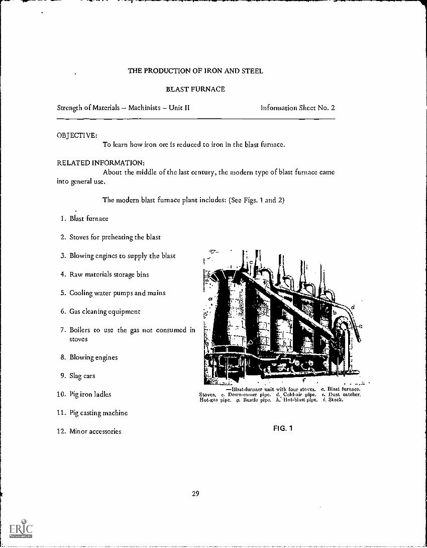
The modern blast furnace plant includes: (See Figs. 1 and 2)
1. Blast furnace
2. Stoves for preheating the blast
. 1.4. Raw materials storage bins
3. Blowing engines to supply the blastc1 /1
5. Cooling water pumps and mains
6. Gas cleaning equipment
7. Boilers to use the gas riot consumed in 4..
stoves
8. Blowing engines
9. Slag cars
10. Pig iron ladles
11. Pig casting machine
12. Minor accessories FIG. 1
.t
t-t
Stoves.Hot-gas
fBlast-furnace unit with four stoves. a. Blast furnace.
c. Down-comer pipe. d. Cold-air pipe. c. Dust catcher.pipe. c. Bustle pipe. it: liot-blast pipe. i. Stack.
29

WASTEWATER
TROUGH
BUSTLEPIPE
CAST IRONCOLUMN
PAVEDFLOOR
...._...Deaign of a modern Man fu ;lace. (Prmn "Modern Refractory Practice,
Harbison-Walker Refractories Co.)
FIG. 2
When a blast furnace is to be "blown in" (started), it must be thoroughlydried before the regular charge can be put into it. Gradually, small charges of ore, coke, andlimestone in proper proportions to the desired grade of pig iron are added until the furnaceis full. Skip cars haul the materials and dump them into the receiving hopper. These skipsare regulated so that the furnace, once started, never stops except for repairs, labor troubles,lack of a market for iron, or for some special reason.
30

A hot blast of air preheated in the stoves is supplied through the tuveres (seeFig. 1). As the process advances, the molten iron and slag collect in the hearth. The heavierh-on settles to the bottom and is drawn from the tap hole (see Fig. 2) near the bottom ofthe hearth every four or five hours. The slag floats on the top and is drawn from the cindernotch which is higher up abort every two hours (see Fig. 2).
As the iron leaves the furnace through trenches (runners), it flows to ladles.Pig iron is taken in the ladles to the pig casting house or to the hot metal mixer where it iskept in a molten state for use in one of the steelmaking processes.
Slag is put into slag cars for transportation to the slag dump for use ascrushed stone. gravel, or part of cement, or is led to the granulating pit for use as a rawmaterial in the making of fireproof and hest- insulating materials.
The blast furnace gas that is produced leaves the top of the furnace throughofftakes leading into the downcomer which takes the gas to the dust-removal equipment.(sec Fig. 1).
The iron that is obtained from the furnace contains a small percentage ofcarbon and varying amounts of silicon, sulphur, phosphorus, and manganese. the amountbeing governed to some extent by the operation of the furnace and depending upon thefuture use of the pig iron.
As you can understand by now, the first product from the iron ore is pigiron. The first process of extracting the iron from the ore is the blast furnace. The pig iron isthe raw material from which all other irons and steels are made;
31
BLAST FURNACE
SHOP NAME
CLASS INFORMATION SHEET NO. 2-2
QUESTIONS
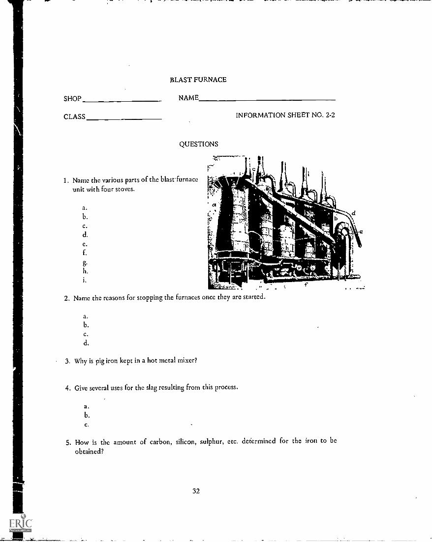
1. Name the various parts of the blast furnaceunit with four stoves.
a.b.c.
d.c.
f.
g.h.
2. Name the reasons for stopping the furnaces once they are started.
a.b.
c.
d.
3. Why is pig iron kept in a hot metal mixer?
4. Give several uses for the slag resulting from this process.
a.b.c.
5. How is the amount of carbon, silicon, sulphur, etc. determined for the iron to beobtained?
32

THE PRODUCTION OF IRON AND STEEL
PUDDLING FURNACE
Strength of Materials Machinists Unit II Information Sheet No. 3
OBJECTIVE:To !tarn how wrought iron is produced.
RELATED INFORMATION:Wrought iron is produced in what is known as a puddling furnace (see Fig. 1
and 2).
-FIG. 1
MODERN HAND-PUDDLING FURNACE
a. Roofb. Chargec. Hearth liningd. Bridge
e. Furnacef. Ash pitg. Charging doorh. Altar
MECHANICAL PUDDLER a. Firc-brick lining. b. Bath. c. Gas intake. d. Discharging door. c. Wastc gas flue to
regenerative chambers. f. Gas flues. g. Roof. h. Charging door. i. Rocker. j. Foundation. k. Pinion.
FIG. 2
33

In the hand puddling process, the operator (puddler) moves the pig ironabout to expose all parts evenly to the reducing flames.
In the mechanical process, the furnace rocks, and causes the metal to flowback and forth over the hearth. The motion has the same effect on the iron as the handpuddling process.
In the puddling furnace the combustion takesplace at one end only. The furnace is linedwith iron oxide which eliminates, in melting,the carbon from the charge of cold pig iron.With the removal of nearly all the carbon andother impurities through hand or mechanicalpuddling, the metal begins to form a pastymass. This pasty mass of metal and slag isstirred until it is formed into or forms a ball.Upon removal from the furnace, the bulk ofthe slag is squeezed from the mass by meansof a mechanical squeezer. (see Fig. 3)
t 11
inniZiftlisejh
OtlitiAtiltAfDINA_ IlielleM-VOL.:4,)
a. Rolls. b. Work.
BAR MILLFIG. 4
C
IfMr:04IN
_ --a. Toothed cylinder.
b. Housing. c. Wrought.iron ball.
MECHANICAL SQUEEZER
FIG.3
.The iron is rolled into bars in thebar mill (see Fig. 4). These bars arecut into short lengths, piled andwired together, heated to weldingheat and rolled into the desiredshapes. The purpose of the stackingand rerolling is a better distributionof the slag.
The Aston-Byers process has been developed for the manufacture ofsynthetic wrought iron. This process uses steeltnaking furnaces to produce a materialdiffering only in that it can be welded more easily than the iron produced by the puddlingprocess.
The principal value of wrought iron is its ability to resist corrosion andfatigue failure. Because of its softness and ductibility, it finds use as bolts, pipe, tubing,nails, ornamental railing, etc.
34

PUDDLING FURNACE
SHOP NAME
CLASS INFORMATION SHEET NO. 2-3
QUESTIONS
1. What is the puddling furnace lined with? Why?
2. How is the bulk of the slag removed from the pasty mass that is taken out of thefurnace?
3. Why are the bars stacked, reheated and rerolled?
4. What does the Aston-Byers process produce?
5. Name several uses of wrought iron.
a.
b.
c.
35

THE PRODUCTION OF IRON AND STEEL
BESSEMER PROCESS
Strength of Materials Machinists Unit II Information Sheet No. 4
OBJECTIVE:To learn how steel is made in the bessemer process.
RELATED INFORMATION:In making Bessemer steel, molten iron from the blast furnace is poured into
the converter as it is tilted on its side. (see Fig. 1)
Righted, air is blown through a number ofholes in the bottom of the converter. Thesilicon and manganese in the molten iron areoxidized with some iron oxide. The mixturerises to the top to form a slag. A brilliantflame shooting from the end of the convertersignals that the carbon has started to burn.When the flame gradually dies down, it shOwsthat the impurities have burned off.
CROSS-SECTION OF TILTEDBESSEMER CONVERTER
FIG. 1
The vessel is tilted again. A charge made up of:1. the amount of carbon needed to bring a specified carbon content,2. manganese to act against the sulphur, and3. silicon to take care of the gases
is added to the molten metal.
The finished steel is poured into a large ladle. From the ladle, it is pouredinto ingot molds for future use in the rollingor forging mills.
Steels made by this process are either acid or basic: acid steel, if the lining ofthe converter was silica,and basic, if the lining was dolomite or magnesite.
Bessemer steel is a low-carbon steel with comparatively low strength,ductibility and toughness requirements, finding use in low-grade sheets, wire, pipe, screwstock, concrete reinforcing, track spikes, and small structural shapes.
While at one time, the cost of the process was low, the lack oflow-phosphorus iron ores has caused an increase in the cost of operations.
36

BESSEMER PROCESS
SHOP NAME
CLASS INFORMATION SHEET NO. 2-4
QUESTIONS
1. What signals that the carbon has started to burn?
2. Why is air blown through the molten iron?
3. When does the operator recharge the converter?
4. Give the composition of the recharge of the converter.
a.
b.
c.
5. What types of steel are produced? Why?
a.
b.
6. Give the characteristics of Bessemer steel.
7. Name five uses of Bessemer steel.
a.
b.
c.
d.
e.
8. Why has the cost of producing steel by this process been increased?
37

THE PRODUCTION OF IRON AND STEEL
OPEN-HEARTH PROCESS
Strength of Materials Machinists Unit II Information Sheet No. 5
OBJECTIVE:To learn how steel is made in the open-hearth process.
RELATED INFORMATION:The making of a typical basic open-hearth steel follows:
CROSS-SECTION OF OPEN-HEARTH FURNACEFIG. 1
1. Furnace (see Fig. 1) is heated with gas flame to make it dry.
2. Calcined dolomite is thrown over floor and walls of furnace.
3. Furnace is mechanically charged with limestone, iron ore and steel scraps
4. Molten iron is added after steel scrap begins to melt (about two hours).
5. Thin slag formation is removed.
6. Heating is continued until scrap melts.
7. Limestone starts to'dissolve into carbon dioxide and calcium oxide.
8. The rising gas forms a thick slag at the surface.
9. Continued heating lowers carbon content to desired percentage.
10. Bath is brought to proper temperature for tapping and pouring.
11. After metal is in ladle, ferromanganese or ferrosilicon is added if a low-carbon or softsteel is desired. Higher carbon steels are made before tapping by adding molten iron andFerro alloys to achieve the desired carbon content.
38

Structural, copper-bearing, spring, boiler, flange, rail, pipe, welding, strip,forging and sheet steels plus sheet bar, tin bar, hoop iron, and screw stock are all products ofthe basic open- hearth process, while the bulk of the acid open-hearth process steel is usedfor forgings and steel castings.
From time to time tests are taken to indicate to the operator how muchprogress has been made in the steel making process. When the metal has reached the qualityrequired, the furnace is brought to the proper temperature for tapping and pouring.
The make-up of the charge, furnace type and size, and steel qualitydetermine the length of heating time. The usual amount of time required may vary from 5to 12 hours.
In the acid open-hearth process no limestone is used, and the slag is formedfrom the iron impurities and the lining of the furnace.
39

OPEN-HEARTH PROCESS
SHOP NAME
CLASS INFORMATION SHEET NO. 2-5
QUESTIONS
1. Why is the open-hearth furnace heated with gas flame?
2. Give the composition of the charge.
a.
b.
c.
3. How is low carbon steel obtained?
4. How is high carbon steel obtained?
5. What is eliminated from the charge in the acid open- hearth process?
6. Name five uses for the basic open-hearth processed steel.
a.
b.
c.
d.
c.
7. Name two uses for the acid open-hearth processed steel.
a.
b.
40

THE PRODUCTION OF IRON AND STEEL
CRUCIBLE STEEL
Strength of Materials Machinists Unit II Information Sheet No. 6
OBJECTIVE:To learn how steel is made in the crucible process.
a. Crucible. b. Charge. c. Ash pit.
d. Melting hole. c. Stack. f. Cellar
CRUCIBLE-STEEL FURNACEFIG. 1
RELATED INFORMATION:In the crucible process, wrought iron or good scrap iron,along with a small
amount of high-grade pig iron and other materials,is placed in a clay crucible. (Fig. 1) Afterthe charge is melted in a gas or coke-fired furnace and the gases and impurities have risen tothe surface, the crucible is taken from the furnace. The slag is removed and the steel pouredinto a small ingot for forging,
The process offers with little or no refining a metal dependent on the purityof the charged materials. Although high-grade tool steels and some alloy steels are still madeby the crucible process, steelmaking in the electric furnace is equal in quality.
41

CRUCIBLE PROCESS
SHOP NAME
CLASS INFORMATION SHEET NO. 2-6
QUESTIONS
1. Give the composition of the crucible furnace charge.a.b.c.
2. Name the uses for crucible steel.a.b.
3. What process can compare in quality with the crucible?
4. When is the crucible taken from the furnace?
5. How is the standard of the metal resulting from the crucible process obtained?
42

THE PRODUCTION OF IRON AND STEEL
ELECTRIC FURNACE STEEL
Strength of Materials Machinists Unit II Information Sheet No. 7
OBJECTIVE:To learn how steel is made in the electric furnace.
FIG. 1 DIRECT -ARC TYPE ELECTRIC FURNACE IN SECTIONAL VIEW
RELATED INFORMATION:The electric furnace (see Fig. 1) has proven to be an ideal melting and
refining unit for the steel industry. The advantages over other steelmaking follow
1. Carbon arc does not oxidize giving pure heat in tightly closed furnace.2. Temperature limited only by furnace lining.3. Regulation and control easily obtained.4. High efficiency.5. Controlled refining and alloying.
43
In most electric furnaces the heat is producedby means of an arc above the bath or bymeans of arcs between the slag and electrodessuspended above the bath (see Fig. 2). Themodern arc-type electric furnace is round inshape and operates on the standard three-phase, three-electrode service arc-type.
Diagram of Arc-Type Electric Steel Furnace
FIG. 2
The extreme importance of the lining or the basic electric furnace is one ofthe principal features of the furnace. The hearth must be made from magnesite or burnerdolomite material to withstand the lime slags used in the basic process. The walls and roofmust be able to withstand extremely high temperatures, silica brick meeting theserequirements.
The bulk of the charge is made up of carefully selected steel scrap that willgive upon melting a smaller amount of alloying elements than is required in the finishedsteel. Ferroalloys and carbon can be added to bring the steel up to the required content.
Tapping starts when the mixture has obtained the proper chemical elements.It is tapped into a ladle, then poured into ingot molds with the greatest of care. The ingothas to be without blowholes, shrinkage holes, etc. if at all possible.
The basic electric process has nearly taken over the market for the finequality and special alloy steels.
As in all acid-type processes for steelmaking, phosphorus and sulfur cannotbe eliminated in the acid-electric process. The d'fference between the acid open-hearth andacid electric processes are that the electric process has better control over all reactions andproduces a cleaner steel.
44

ELECTRIC FURNACE STZ.zL
S HOP NAME
CLASS INFORMATION SHEET NO. 2-7
QUESTIONS
1. Name the advantages of the electric furnace process over other processes ofsteelmaking.
a.
b.
c.
d.
c.
2. How is the heat produced in an electric furnace?
3. Explain the lining used in the basic electric furnace.
4. Name the use for the basic electric furnace steel.
5. Does the acid open-hearth or acid electric process produce a cleaner steel?
Ask your instructor for Achievement Test No. 2 after you complete the work in this unit.
45

PRODUCTION OF NON-FERROUS METALS
ALUMINUM
Strength of Materials Machinists Unit III Information Sheet No. 1
OBJECTIVE:To learn how aluminum is produced.
RELATED INFORMATION:Aluminum, about twice as plentiful as iron, rates third behind oxygen and
silicon in its abundance in the earth's crust.
Aluminum is secured commercially from an ore known as bauxite. Bauxiteores can be found in North and South America and in Europe. France's high-grade oresupplies the bulk of Europe, while Arkansas rates ahead of Georgia as the supplier in ourcountry.
Because bauxite is too impure to use in direct electrolytic reduction, twoprocesses must be used.
1. Bayer process to purify ore and produce alumina.
2. Hall- Heroult process which reduces the alumina to aluminum by electrolysis.
In the Bayer process, the aluminum oxide is dissolved from the bauxite byuse of caustic soda. Filtering removes the impurities. It is separated as aluminum hydratc,and calcined (reduced to a powder) to form alumina (aluminum oxide).
b
c -
4-4-8-8-1111;1111111121; 0,4
eL,PEI
d
9
k
Hall-Heroult electric aluminum, furnace. a. Steel shell.b. Electric insulation. e. Carbon lining. d. Bus bar. e. Carbon (posi-tive) electrodes. J. Negative connection (collecting plate). p. Frozencrust of electrolyte and aluminum. h. Ladle. i. Molten electrolyte.j. Molten 1uminum. k. Concrete floor.
CROSS-SECTION HALL-HEROULT ELECTRIC ALUMINUM FURNACEFIG. 1
46
k
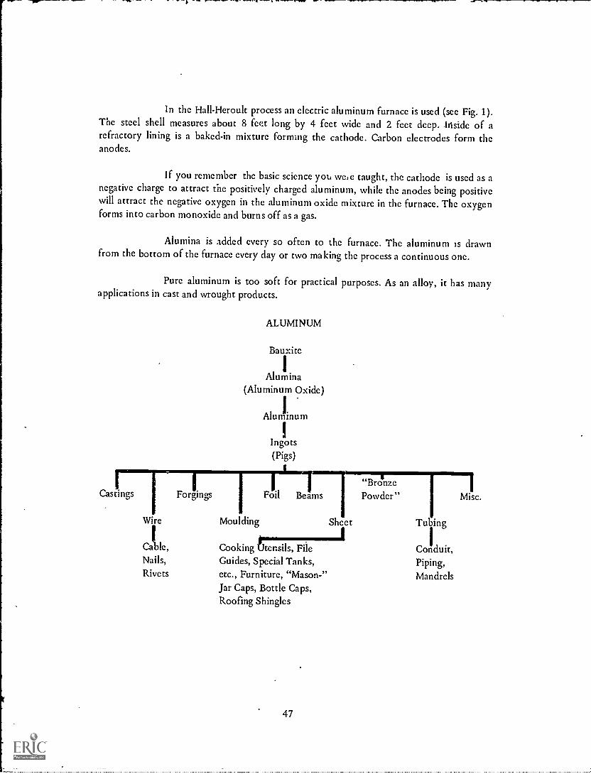
In the Hall-Heroult process an electric aluminum furnace is used (see Fig. 1).The steel shell measures about 8 feet long by 4 feet wide and 2 feet deep. Inside of arefractory lining is a baked-in mixture forming the cathode. Carbon electrodes form theanodes.
If you remember the basic science yot, we, e taught, the cathode is used as anegative charge to attract the positively charged aluminum, while the anodes being positivewill attract the negative oxygen in the aluminum oxide mixture in the furnace. The oxygenforms into carbon monoxide and burns off as a gas.
Alumina is added every so often to the furnace. The aluminum is drawnfrom the bottom of the furnace every day or two making the process a continuous one.
Pure aluminum is too soft for practical purposes. As an alloy, it has manyapplications in cast and wrought products.
ALUMINUM
Bauxite
IAlumina
m Oxide)
Aluminum
Ingots(Pigs)
Castings Forgings Foil Beams"BronzePowder" Misc.
Wire Moulding Sheet ing
Calble, Cooking tensils, File Conduit,Nails, Guides, Special Tanks, Piping,Rivets etc., Furniture, "Mason-" Mandrels
Jar Caps, Bottle Caps,Roofing Shingles
47

ALUMINUM
SHOP NAME
CLASS
QUESTIONS
1. Name the ore from which aluminum is extracted.
2. Where is the ore found in the United States?a.b.
INFORMATION SHEET NO. 3-1
3. Identify the processes used to produce pure aluminum.a.b.
4. What is the chemical name for aluminum?
5. What is a disadvantage of pure aluminum?
6. State the applications of aluminum as an alloy.a.b.
7. Why can't bauxite be used in direct electrolytic reduction?
48

PRODUCTION OF NOT I-FERROUS METALS
COPPER
Strength of Materials Machinists Unit III Information Sheet No. 2
OBJECTIVE:To learn how copper is produced.
RELATED INFORMATION.Copper ores can be found scattered over the face of the earth. United States,
Chile, and Africa are ranked according to their place in the mining of the ore.
Before copper ore can be smelted at a profit,the separating of the ore and worthless rock isnecessary through a floatation machine (seeFig. 1) or a concentration table (see Fig. 2).
Principle of floatationa. Tank b. Solution c. Air bubble
d. Worthless rock e. Richer oreFIG. 1
Itth7+:1111;P)11110)119P111191,11191191'119,MIVIZI;ft- "-
I; t:'111
111'11111 IIIIQIIIINIIIIIIiIIII 1-
Oreconcentrating table. a. Table. b. Launder.c. Feed. d. Concentrates. e. Shaking mechanism.f. Slime. g. Concentrate box.
FIG. 2
The generally used floatation process causes the richer pieces of ore to float.The finely powdered ore is put into a tank containing a solution of water, pine oil and somechemicals. The solution is stirred and creates little air bubbles covered with oil. The oil-covered bubbles attach themselves to the richer pieces of ore as they float to the surface ofthe tank. The ore is filtered and roasted to remove as many impurities as possible.
In the concentration process, finely crushed ore is run on the tables in water.A jerking motion causes the heavier material to collect in grooves and pass out at each endof the table. The lighter materials are forced over the ridges and pass off at one side.
Smelting of copper starts in a reverberatory furnace (similar to open-hearthfurnace). The fuel used may be pulverized coal or fuel oil. The result of smelting is a crudecopper matte which in the molten state goes to the converters or oxidizing furnaces forfurther refining.
49

A typical converter works in a similar manner to theBessemer converter. The blister-like appearingproduct is nearly pure copper. The blister copper goesthrough continued refining in reverberatory furnaces.The copper is cast into anodes similar to the oneshown in Fig. 3.
THIN, ALMOST PURE COPPERSHEETSFIG. 4
750 LB. ANODESFIG. 3
The next to last step is to remove allremaining foreign metals byelectrolysis. In the electrolyticprocess, a typical plant is equippedwith lead-lined tanks, fitted on :hetop edges to supply electricity.Copper sulphate and sulphuric acidpartly fill the tank. Into the tanks goanodes and cathodes (see FLg. 4), tohang in such a way as to form thepositive and negative poles of anelectric current.
The multiple and series methods are used to arrange the copper castings andsheets. A current of 7,000 amperes is sent through the solution,which dissolves the copperfrom the anodes and deposits it on the cathodes.
The gold, silver, arsenic, and other non-copper metalsare released. They settle to the bottom of the tank inthe form of slime,which is cast for refining.
When the cathodes have increased their weight toabout 170 pounds, they are replaced by new, thinstarting sheets.
Electrolytic copperrefining tanks or cells. ASeries process. B. Multiple process. a. Wooden orcement tank. b. Lead lining. c. Slime. d. Anodes.c. Cathodes.
FIG. 5
The product, about 99.98% pure, is ready for final melting and refining inlarge reverberatory furnaces. The steps consist of:
1. Charging Machine puts cathode in sheets in furnace.
2. Melting Blending of copper.
3. Oxidizing Cuprous oxide is added to the molten copper to oxidize all impurities.
50
4. Poling With a covering of coke or charcoal over the bath, poling begins. Butt endsof green poles are forced underneath the surface of the metal. The violentaction causes a reduction of the dissolved cuprous oxide.
5. Casting Molten copper cast into commercial shapes.
Most of the copper produced is used for electrical purposes. Aboutone-fourth is used in making brass, bronze, and other copper alloys.
51

COPPER
SHOP NAME
CLASS INFORMATION SHEET NO. 3-2
QUESTIONS
1. Name several places where copper ore is found.
a.
b.
C.
2. State two methods 'Bed to separate the ore and worthless rock.
a.
b.
3. What furnaces are used in various steps of producing copper?
a.b.
4. How pure is the product after the electrolytic process?
5. Name several uses for copper.a.b.C.
52

PRODUCTION OF NON-FERROUS METALS
LEAD, TIN, ZINC
Strength of Materials Machinists Unit III Information Sheet No. 3
OBJECTIVE:To learn how lead, tin and zinc are produced.
RELATED INFORMATION:An ore known as galena and containing lead sulphide, zinc, copper, silver,
arsenic, iron, and other metals is found in great abundance in the western part of the UnitedStates.
Mining of lead follows steps similar to those of copper mining. Theconcentrates are calcined (made powdery by heat action) to remove the sulphur and meltedtogether for smelting. Mixed with flux and coke and smelted in a blast furnace, similar toiron-ore smelting, a lead bullion containing lead and some of the other metals is obtained.
Continued refining of the lead bullion by removing the copper, arsenic, iron,silver and other metals gives a lead nearly 100% pure.
Lead can be used for sheets, pipes, tank linings, tubes, cable coverings, foil,battery plates, bullets and enamels. Alloyed with tin, it makes solder, while lead, tin, andantimony make bearing or type metal. Oxidizing the lead gives white and red lead.
Tin ore must be concentrated like the previous non-ferrous metals before itcan be smelted. The concentrates are prepared for smelting according to the impurities theymay contain.
When sulfur is present,roasting takes place to remove it. Other impurities areoxidized and washed out by an acid and hot-water treatment.
The tin oxide must be smelted in a reducing furnace (reverberatory) in thepresence of a flux of carbon. So that as much tin can be released as possible, a limestoneflux is also used. Because a lot of tin passes off through vaporization, the waste-gas flues areconnected with a recovery system.
The tin bullion is refined,and a cleaning process in large kettles causes theimpurities to rise to the surface, where they are removed. The tin is cast into pigs forcommercial use.
Tin is used mostly for tin plate or containers.
53

Zinc ores are widely distributed. For the most part, after concentration, thefloatation process is used. An exception is the northern New Jersey deposits, where anelectro-magnet extracts the large amount of iron in the ore before it can be processed.
In extracting the metal from the concentrates, any one of three processes isused. They arc:
1. Ordinary distillation2. Electrothermai distillation3. Electrochemical treatment
Eighty or ninety small clay retorts charged with a mixture of calcined oreand coal or coke are placed in a special furnace in the ordinary distillation process. Thetemperature is raised until the zinc boils and passes off as a vapor. The vapor is condensedinto zinc in a special condensing chamber. The zinc is cast into commercial forms while thematerial left in the retorts is reworked to recover any other metal that will show a profit. .
The electrochemical process uses an electric furnace to obtain the vaporizingof the metal and the follow-up is similar to the ordinary distillation process. Cost ofoperating the furnace is high if electricity cannot be obtained cheaply. This process is usedonly in Sweden where only a small percentage of zinc is refined.
The electrochemical process is divided into a leaching and separation of thezinc from a solution.
The concentrates are roasted to drive off water, sulfur and other impurities.The resulting material is treated with sulphuric acid to dissolve the zinc and precipitate theiron, copper: and other metals.
The pure solution is run into lead-lined electrolyzing tanks for separation.Lead anodes and thin sheets of aluminum cathodes are used. When the current is turned on,the zinc separates from the solution and deposits itself on the aluminum sheets. It is peeledoff the sheets and is ready for casting into commercial forms. The acid solution can be usedover again in the process.
Zinc is used as a galvanizing material and,alloyed with copper, makes brass.Zinc oxide finds use in paints.
54

LEAD, TIN, ZINC
SHOP NAME
CLASS INFORMATION SHEET NO. 3-3
QUESTIONS
1. What is the ore from which tin is extracted?
2. Where is an ore known as galena found?
3. Name some of the metals found in galena.a.b.c.
d.e.f.
4. What exception in the processing of zinc ores from North Jersey deposits has to beconsidered? Why?
5. Name five uses of lead.a.b.c.d.e.
6. Why is a limestone flux used in the smelting process of tin?
7. What is tin used for?a.b.
8. Name three processes that can be used to extract zinc from the ore.a.b.c.
9. Which process would be too costly to use in sonic sections of the United States?
10. Give two uses of zinc.a.b.
55

PRODUCTION OF NON-FERROUS METALS
CADMIUM
Strength of Materials Machinists Unit III Information Sheet No. 4
OBJECTIVE:To learn how cadmium is produced.
RELATED INFORMATION:Cadmium is probably the first metal that was not discovered as an ore.
Cadmium is obtained, as a by-product in the production of zinc and sometimes lead. It isrecovered from the fumes produced in the roasting process of zinc, from the powder formedduring zinc distillation, from tank solutions in the electrolytic refining of zinc, from the leadfurnace fumes. Three methods of obtaining cadmium arc:
1. Redistillation of zinc or lead by-products.
2. Electrolytic methods.
3. Precipitation with zinc.
Cadmium alloyed with tin, lead and bismuth forms a low-melting-pointmaterial that is used in sprinkler heads, fire alarms, electric fuses, and safety plugs in boilers.Other cadmium alloys find use in sterotype plates and rust-proof coatings.
56

SHOP
CLASS
CADMIUM
NAME
QUESTIONS
INFORMATION SHEET NO. 3-4
1. How does cadmium differ from other metals with regard to its source?
2. How is cadmium obtained?
3. Give some uses of cadmium.
a.b.c.
4. Name three methods of obtaining cadmium.
a.b.c.
57

PRODUCTION OF NON-FERROUS METALS
MAGNESIUM
Strength of Materials Machinists Unit III Information Sheet No. 5
OBJECTIVE:To learn how magnesium is produced.
RELATED INFORMATION:Magnesium has become one of the most important of the non-ferrous metals
because of the demand for very strong and very light metal products in aircraft design. It ismalleable, ductile and possesses a high tensile strength when alloyed, but corrodes in saltwater, salt air, and in most acids.
Large amounts of natural ores of magnesium (magnesite) are found inAustria, Greece, Russia, and along the Pacific Coast of North America.
At present, nearly all of the commercial magnesium is obtained by the directelectrolysis of natural salts.
The initial step in the production of magnesium is to get magnesiumchloride. This salt is recovered in the purifying of sodium chloride found in salt wells orextracted from sea water.
A melted mixture of the chlorides of sodium, potassium, and magnesium iselectrolyzed in an airtight iron vessel. The walls of the vessel act as a cathode, and there is acentrally located anode of graphite. As the magnesium is freed from the mixture, it rises tothe surface and is ladled out.
The metal is refined by remelting it in iron pots, fluxed with sodiummagnesium chloride to remove oxides. If the magnesium needs to be nearly pure, adistillation process is added.
Pure magnesium is used in the form of ingots, bars, rods, wire, tubes, ribbon,sheets, and powder. A good percentage of magnesium goes into alloys to form sheets, wire,rods and structural shapes. Magnesium powders find use in flashlight work and for varioussignaling devices.
58

MAGNESIUM
SHOP NAME
CLASS INFORMATION SHEET NO. 3-5
QUESTIONS
1. Why has magnesium become so important as a non-ferrous metal?
2. State some physical characteristics of magnesium.a.b.c.d.
3. How is commercial magnesium obtained?
4. Give several uses of pure magnesium.a.b.c.
5. What are two other uses for magnesium ?a.b.
59

PRODUCTION OF NON-FERROUS METALS
NICKEL
Strength of Materials Machinists Unit III Information Sheet No. 6
OBJECTIVE:To learn how nickel is produced.
RELATED INFORMATION:The most important nickel deposits are foui,(1 in the Sudbury district of
Ontario, Canada. The ores are imported to the United States because only a small quantityof nickel is produced from the nickel salts recovered in the refining of blister copper.
In the Sudbury district the coayse concentrates are smelted in blast furnaceswhile the fine concentrates are put into a reverberatory furnace. The matte resulting fromthe smelting is bessemerized to remove the iron. The Bessemer matte consists chiefly ofcopper and nickel sulfides.
The two principal processes of extracting nickel from the copper-nickelmatte arc:
1. Orford, wherein the product as cast from the blast furnace makes a two-layer solid.The top layer contains copper sulfide, while the bottom layer is of nickel sulphide,which is refined electrically.
2. Mond, which consists of vaporizing the cast nickel into a carbon monoxide gas andnickel.
Nickel finds great use because of its resistance to atmosphere and chemicalcorrosion, and the ability to take a high polish. Vats, and vessels in the chemical industry andelectroplating of hardware make good use of nickel, while alloys of nickel take a greatamount of the metal.
60
NICKEL
SHOP NAME
CLASS INFORMATION SHEET NO. 3-6
QUESTIONS
1. Where are large deposits of nickel ores found?
2. State the two principal processes of extracting nickel from the copper-nickel matte.
a.b.
3. Why is nickel an important non-ferrous metal?
a.b.
4. Give two uses of nickel.a.b.
61

PRODUCTION OF NON-FERROUS METALS
ADDITIONAL NON-FERROUS METALS
Strength of Materials Machinists Unit III Information Sheet No. 7
OBJECTIVE:To learn how some of the other non-ferrous metals are produced.
RELATED INFORMATION:Some of the remaining non-ferrous metals that will be briefly sketched as to
their production methods are antimony, manganese, chromium, tungsten, molybdenum,vanadium. bismuth, cobalt, mercury, titanium, gold. and silver.
Antimony is obtained as a by-product in lead refining or by heating the oreknown as stibnite with scrap iron. The pure metal does not find industrial use, but is alloyedwith metals to give them hardness and the ability to be cast with sharp detail.
Manganese is another metal that is not used in its pure state. Instead, it findsuse as an addition to ferrous metals and alloys to make them easier to forge. It is producedas a commercial metal by the Thermic process (reduction with aluminum) or asferromanganese by preparation in an electric furnace.
Chromium has the advantage of being harder and more resistant to corrosionthan nickel. It has replaced the latter metal in sonic applications of electroplating. It isprepared by the Thermic process. Chromium, also, finds use added to steel and alloyed withnickel.
The principle use of tungsten is in the electric light bulb as a filament. Otheruses are phonograph needles, heating elements in very high temperature furnaces, and partof high-speed steel. Tungsten is obtained as an oxide from the ore. Reduction of thetungsten oxide produces a metallic tungsten pov.-tier. The hot powder is placed in dies andpressed. By repeated heating and hammering, a solid bar of metal is obtained.
To produce molybdenum, an ore, molybdenite, is concentrated by afloatation process, roasted, and reduced by carbon in an electric furnacc,. The chief use ofthe metal is in the manufacture of high-tensile steels.
Vanadium is used mainly in the making of vanadium steel for use as springsor hand tools. The making of pure vanadium is difficult and very li-cle is produced forcommercial purposes. Rather, the reduction of the ore (patronite) and flux is done in ancicctric furnace.
Bismuth is a by-product of the lead-refining process. Combined with lead, tinand cadmium to form a low-melting alloy, it finds similar uses to cadmium on sprinklerheads, fire alarms, etc.
62
Cobalt, similar to nickel, is used as a part of certain special steels.
Mercury is the only common metal that is liquid at ordinary temperatures. Itis produced by roasting, vaporizing and condensing. Most of the mercury in this country isused in the form of mercury compounds in blasting caps, for coloring red rubber products,and red oxide of mercury paint, while only a small amount goes into thermometers.barometers. and other laboratory apparatus.
Titanium is reduced by means of the Thermit process. Because it formscompounds with carbon, nitrogen, and silicon at high temperature, it is hard to make themetal in a free state. It finds use in the making of steel and as a white pigment in paintproducts.
The use of gold and silver in coins and jewelry needs little explaining. Gold isthe standard of value and basis of the Ur:ted States system of money because of itspermanence and rarity. Most of the gold and silver presently produced is recovered asby-products of lead, zinc, and copper refining.
63

ADDITIONAL NON-FERROUS METALS
SHOP NAME
_ CLASS INFORMATION SHEET NO. 3-7,
QUESTIONS
1. Name the non-ferrous metals that cannot be used commercially in their pure state.a.b.c.
2. List a use for the following metals:a. Goldb. Titaniumc. Mercuryd. Vanadiume. Silverf. Tungsteng. Molybdenum
3. What metal is alloyed to make the material easier to forge?
4. Why has chromium replaced nickel in some instances for electroplating?
5. What metals are combined with bismuth to make a low-melting alloy?a.b.c.
Ask your instructor for Achievement Test No. 3 after you have completed the workin Unit III.
64

GENERAL PHYSICAL PROPERTIES
INDUSTRIAL MATERIALS
Strength of Materials Machinists Unit IV Information Sheet No. 1
OBJECTIVE:To acquaint the student with the general physical properties of industrial
materials.
RELATED INFORMATION:Let us sec why industrial materials have come to play such a large part in
man's daily life. Wood and stone, oldest in use, are being slowly replaced by other industrialmaterials. An example is the variety of exterior coverings for buildings that the builders are
ng.
Some of the reasons for this change in the use of materials may be seen inthe greater strength, toughness, resistance to weather, and workability of the new products.
Metals, more than any of the other industrial materials, show many reasonsfor their greater use. Metals can be cast in varied shapes, forged, formed, welded, repaired,remelted, and used over again.
The selection of the proper industrial material for a given use is an importantpart of good design practice. For instance, strength, ease of shaping and low cost are of greatimportance for strurtuiai work. For these purposes, steel is best suited to satisfy therequirements. However, if corrosion resistance is required, non-ferrous alloys or plasticproducts would have to be used.
Where ease of-machining is more important than strength,as is the case in themaking of screws, the required industrial material could be steel or brass. If a casting doesnot require great strength, cast iron or cast brass can be used.
Steel which can be made soft or hard by heat treatment is used in the toolindustry.
Metals light in weight for use in various ways are aluminum or magnesiumand their alloys, while for softness and ease in bending, a necessity in the electrical andplumbing fields, lead, copper, plastics, and rubber find industrial uses.
Copper, aluminum. and silver are the best conductors of electricity, withcopper getting the greatest use because of its lower cost in giving a finished product.
Resistance to heat, electrical resistance, the melting point of a material,coefficient of expansion, and specific gravity must be taken into consideration whenspecifying an industrial material for practical use.
If all these properties, as outlined, are taken into consideration when youspecify a material, the finished product should be well worth a place on the open market.
65

INDUSTRIAL MATERIALS
SHOP
CLASS
NAME
QUESTIONS
INFORMATION SHEET NO. 4-1
1. What are some of the reasons for the change in use of industrial materials?a.b.c.d.e.
2. Why are metals considered good materials to use in making products?a.b.c.d.e.f.
g.
3. What must be taken into consideration in the design of industrial structures?a.b.c.
4. Why is copper used for electrical wiring?
5. Give the necessary requirements for materials in the electrical and piping industries.
a.b.c.d.e.
66

GENERAL PHYSICAL PROPERTIES
STRENGTH
Strength of Materials Machinists Unit IV Job Sheet No. 1
OBJECTIVE:
WANTED:
To learn how various materials differ in strength.
Results of various tests.
MATERIALS:Pieces of cast iron, wood, plastic, rubber, wrought iron, mild steel, brass,aluminum, hammer, vise.
PROCEDURE:1. Strike each of the materials a blow with a hammer. Do the materials shatter.
dent or withstand the blow of the hammer? Record your results.
2. Place your piece of material in the vise in such a manner that you can see ifit will bend when you hit it on the side. Don't hit the material so hard that itwill break.
67

GENERAL PHYSICAL PROPERTIES
HARDNESS
Strength of Materials Machinists Unit IV Job sheet No. 2
OBJECTIVE:
WANTED:
To determine the hardness of various industrial materials.
Comparison of the hardness of the different industrial materials.
MATERIALS:Pieces of cast iron, wood, plastic, rubber, wrought iron, mild steel, tool steel,brass, aluminum, Rockwell Hardness Tester.
PROCEDURE:(To be done in machine shop)
1. The instructor will demonstrate how the Rockwell Hardness Tester is used tomeasure the hardness of the materials.
2. Record your results.
68
GENERAL PHYSICAL PROPERTIES
WEIGHT AND DENSITY
Strength of Materials Machinists Unit IVJob Sheet No. 3
OBJECTIVE:
WANTED:
To learn that weight and density have an important bearing on the use of
materials.
Reasons for using weight and density.
RELATED INFORMATION:A major goal of product design in the competitive market is decreased size
and weight and increased strength. You can read or see in the newspapers or trade magazines
the many improvements in the overall size of objects. Not so many years ago, an automobile
as we know it today was only a dream. The advances in the use of metal techniques has
given us many structural advantages in the car you see in the showroom and on the street.
Early airplanes were covered with a fabric material, yet only a few years after the invention
of the plane, engineers were hard at work on an all-metal aircraft structure.
Weight and density, then, play an important part in the size and make-up of
an object. Weight is a means of telling the difference between objects, while density of a
material is its weight per unit volume. For example, one talks about the weight of an object
in pounds (lbs.) or ounces (oz.) while the density is thought of arid referred to in pounds per
cubic inch (lbs./cu.in.) or pounds per cubic foot (lbs./cu.ft.).'
The importance of knowing the weight of an object is realized in its use. The
bulldozer operator likes the heavy equipment he is using.because he knows he will get the
job done. The pilot of an airplane feels secure in the knowledge that he has a craft that will
fly under certain load conditions. The weight requirements have been figured by the
engineering department after studies of many experiences. You will discover in your work
experience that where weight has been ignored in the design of a machine, vibration or
failure to perform the required work will be the result.
Density gives the machinist a quick reference to guide him in the weights of
materials. Look at the tables in the Machinery's Handbook in the section listed in the table
of contents as "Properties and Weights of Materials". Sheets, bars, rods, etc. are listed as a-
convenience in estimating weight. For example, if you needed to use a piece of steel Yz"
diameter and 12 inches long to make an adjusting screw shank, the weight of the material
could be found by checking the table for weights of square and round steel bars which
would be 0.850 lbs. You may think that weighing the piece would be easier and quicker, but
sometimes a spring scale is not available.
69

.....1.11.6)
The weight and density of materials are used to a great extent in estimatingfrom blueprints. A customer submits a blueprint of an object to be made. Cost has to befigured for the machining time and the material. The densities of the various parts or thesize and length can be found. With this information and using a reference book, the materialweight can be found. Then, it is an easy matter to get the cost per pound of the materialthat has to be used. A complete bid can be submitted which will produce the article at a-profit.
TOOLS AND MATERIALS:1/2" diameter x 6" long bars of aluminum, brass, and steel, and spring balanceor balance scale.
PROCEDURE:1. Weigh each of the bars of metal.
2. Record the weights.
3. Check a reference table to see if your weights are in agreement.
70

WEIGHT AND DENSITY
SHOP NAME
CLASS JOB SHEET NO. 4-3
QUESTIONS
1. What is a major goal of product design?
2. Describe the difference between weight and density.
3. Give examples where weight in an object is important.
4. Could you estimate the weight of an object from a blueprint.? Explain.
5. Fin: - weights of the followingusing a reference table:a. .1 piece of No. 24 copper sheet having ar: area of 1 sq. ft.
b..41- dia. x 12 in. long brass bar.
c. Aluminum bar, 1" dia. x 6 in. long.
71

li
GENERAL PHYSICAL PROPERTIES
EXPANSION
Strength of Materials Machinists Unit IV Job Sheet No. 4
OBJECTIVE:
WANTED:
To show that materials expand.
Cause of expansion of materials.
RELATED INFORMATION:Did you ever notice and wonder why spaces were left between the concrete
slabs on a highway? Or did you ever see a section of a highway buckle? The buckling wascaused by too small an allowance of space between the slabs of concrete. As a result, on ahot day the concrete kept expanding until the only place it could go was up.
Be alert, when you work with materials, to the fact that they expand,otherwise you will run into trouble if you don't make allowance for the expansion.
MATERIALS:Piece of polished steel 1/2 inch in diameter and six inches long, electricfurnace, ring that just fits on steel rod.
PROCEDURE:
(This experiment should be conducted in the machine shop by the shopinstructor).
1. Heat the bar until it becomes blue.
2. Show how the bar will not fit into ring.
3. Cool the bar.
4. Heat the ring and see if the bar can be inserted into it.
....,..qt...
Ask your instructor for Achievement Test. No. 4 after you have completed the workin this unit.
72

MECHANICAL PROPERTIES OF MATERIALS
ELASTICITY AND TOUGHNESS
Strength of Materials Machinists -- Unit V Job Sheet No. 1
OBJECTIVE:
WANTED:
To learn how the elasticity and toughness of a material are measured.
Method of measuring elasticity and toughness.
RELATED INFORMATION:That stone is stronger than wood was common knowledge to our forefathers
long before we began to set down rules as to the strength of materials. The need for speedierand economical development of materials led to demands for research and testing of thesematerials to prove their worthiness. The purpose of the testing laboratories is to check or tolearn the strength and properties of materials. This procedure sets a standard wherebyuniform material is obtained.
Two of the important properties of a material are its elasticity and itstoughness.
Elasticity is the ability of a material to return to its original form after a loadhas been applied and removed.
Toughness is that ability of a material to undergo great change in shape orform under high stress before it breaks down.
If too heavy a load is applied to a material, it will not return to its originalform. In this case, the elastic limit has been reached.
You, as a machinist, should know the limits of the materials in order tomake the finished product sound in quality, economy, service, and performance.
TOOLS AND MATERIALS:Various types of wire, measuring stick, micrometer, tension machine.
PROCEDURE: (Demonstration by the instructor).1. Place the wire in the tension machine.
2. Measure the diameter and length of the wire. Record your measurements. Weightindicator should be at zero.
73
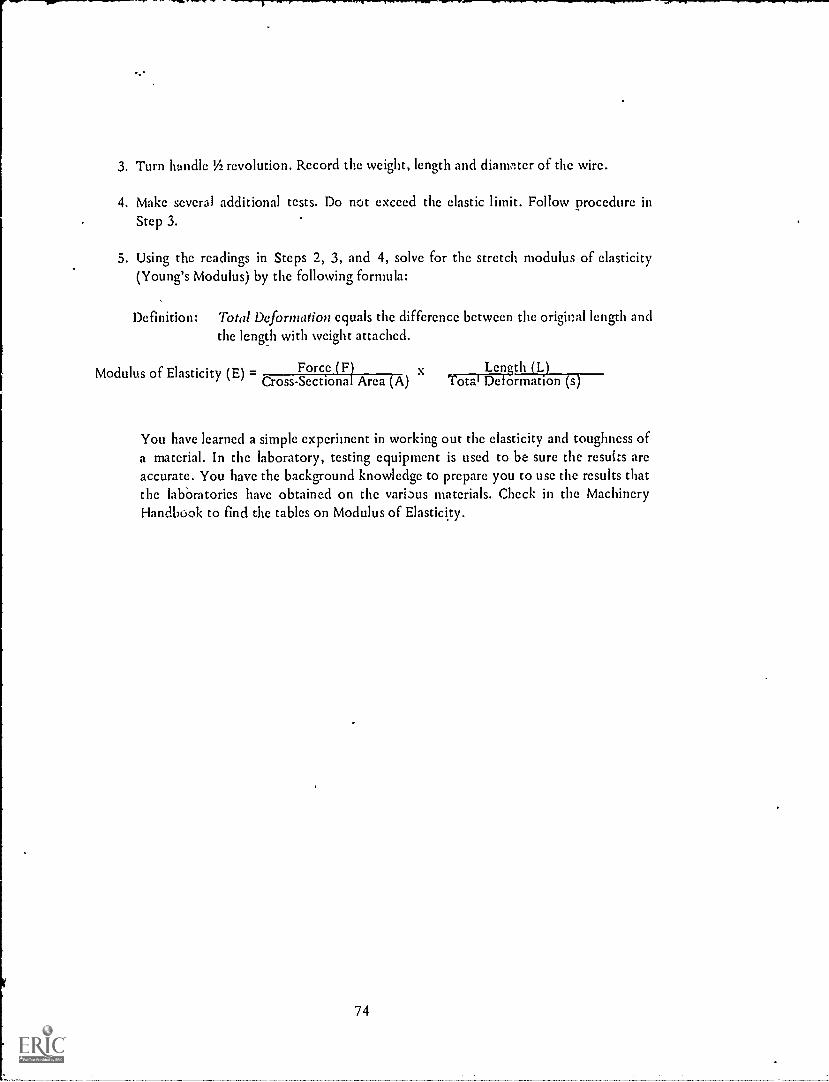
3. Turn handle 'h revolution. Record the weight, length and diameter of the wire.
4. Make several additional tests. Do not exceed the elastic limit. Follow procedure inStep 3.
5. Using the readings in Steps 2, 3, and 4, solve for the stretch modulus of elasticity(Young's Modulus) by the following formula:
Definition: Total Deformation equals the difference between the original length andthe length with weight attached.
Modulus of Elasticity (E) = Force (F)Cross-Sectional Area (A)
x Length (L)Total Deformation (s)
You have learned a simple experiment in working out the elasticity and toughness ofa material. In the laboratory, testing equipment is used to be sure the results arcaccurate. You have the background knowledge to prepare you to use the results thatthe labOratories have obtained on the various materials. Check in the MachineryHandbook to find the tables on Modulus of Elasticity.
74

4
NS
fRA
5
t.$
ELASTICITY AND TOUGHNESS
SHOP NAME
CLASS JOB SHEET NO. 5-1.
PROBLEMS
A. 1. A steel bar, 48 inches long having a cross-sectional area of I square inch has a forceof 12,000 lbs. pulling at its suspended end. if the force lengthens the bar 0.02 of aninch, what is the modulus of elasticity?
2. A wrought iron rod having a cross-sectional area of 7 square inches and 60 incheslong stretches 0.001 inches when a load of 900 lb. is hung at the end of the rod.Find the modulus of elasticity for wrought iron. (Check your answer with theMachinery's Handbook).
J. An average cast iron bar is 2 square inches in cross-sectional area and is 32 incheslong. What will the modulus of elasticity be if a load of 500 lbs. stretches the bar.0005 inches?
B 1. A carbon steel rod V2" x 1" and 6%4 feet long is stretched 0.015 inches when a loadof 3000 lbs. is attached to it. What is the modulus of elasticity for the steel?
2. A piece of structural steel having a cross-sectional area of 3 square inches has aweight of 30,000 lbs. suspended from it. How much longer is it after'the load isapplied? (Hint: Look up modulus of elasticity for structural steel in theMachinery's Handbook and substitute in the. formula).
C. 1. From experiments it is known that the modulus of elasticity for a certain type ofsteel is 29,000,000 pounds per square inch. What will be the total deformation in astrap, 1' /z inches in diameter and 61/2 feet long, when a stress of 6000 lbs. is appliedto the rod?
I
75

MECHANICAL PROPERTIES OF MATERIALS
DUCTILITY AND HIGH TEMPERATURE STRENGTH
Strength of Materials Machinists Unit V Job Sheet No. 2
OBJECTIVE:
WANTED:
To learn what ductility in industrial materials means.
Difference in ductility of various industrial materials.
RELATED INFORMATION:If a material resists rupture when greatly extended in tension, is is said to be
ductile. Because of ductility, metal can be drawn into wire. To be formed in this manner, ametal must show good tensile strength after great deformation. Lead, for example, althougheasily deformed, cannot be drawn into wire because of its low tensile strength.
decreases.If heat is applied to most materials, it has been found that their strength
A
MATERIALS:Steel and copper wire, weights, Bunsen burner or some other suitable heat.
PROCEDURE: (Demonstration by the instructor)1. Keep adding weights to the steel wire as shown in Fig. A until the wire
breaks. Record weights and size of wire.
2. Follow same procedure with the copper wire. Record results.Ilk
3. As you add weights to the steel wire, ar'f heat as shown in Fig. B. See if ittakes less or more weight to break wire. Record results.
76

DUCTILITY AND HIGH TEMPERATURE STRENGTH
SHOP
CLASS
1. What is meant by ductility?
NAME
QUESTIONS
2. Give five examples of ductile materials.a.b.c.d.e.
JOB SHEET NO. 5-2
3. After great deformation, the metals must show what characteristic to be consideredductile?
4. What does heat do to strength of most material?
5. Give the order in which two metals tested in the experiment would be measured as totheir ductility. (Percent of stretch and percent of reduction of their area).
a.b.
77

CP
MECHANICAL PROPERTIES OF MATERIALS
STIFFNESS
Strength of Materials Machinists Unit V Job Sheet No. 3
OBJECTIVE:To learn why stiffness of materials is often necessary.
RELATED INFORMATION:Stiffness is that property of a material whereby it can support a large load
without losing its shape.
Look at the machines in your shop or the tables and chairs in the scienceroom. If they were not provided with proper support, either a shaking action or bucklingmight result.
The knowledge that the lathe center, tool bits, broaching bar, etc. areexamples of materials requiring stiffness as one means of performing work sholid helpyouin trade as a machinist.
MATERIALS:Two steel rods of different diameters, compression machine.
PROCEDURE: (Demonstration by the instructor)
1. Insert the small-diameter steel rod into the compression machine.
2. Apply pressure. Does the rod bend?
3. Try the same procedure with the larger diameter rod in the same material.What happens?
78

SHOP
CLASS
1. What is stiffness?
STIFFNESS
NAME
JOB SHEET NO. 5-3
QUESTIONS
2. Give five examples of stiffness as it is applied to the machines in the shop.a.b.c.d.e.
3. The legs on the stools at the work benches are made of angle iron. Explain the reasonfor using this material instead of flat rectangular or square stock.
4. Explain why a small aill in a drill press buckles when fed into the work too rapidlyand with too much pressure.
79
MECHANICAL PROPERTIES OF MATERIALS
HARDNESS
Strength of Materials Machinists Unit V Job Sheet No. 4
OBJECTIVE:To learn how different materials have varying hardnesses.
WANTED:Hardness values of some materials.
RELATED INFORMATION:Hardness is the resistance that a substance offers to the separation of its
particles by the penetrating action of another substance.
TOOLS AND MATERIALS:-Rockwell Hardness Tester, pieces of cast iron, cold-rolled steel, hot-rolled -
steel, tool steel, brass.
PROCEDURE: (test demonstration to be done by machine shop instructor)
1. Test each piece of metal in the Rockwell Hardness Tester.
2. Record results of the tests.
3. List the different metals in the order of their hardness.
80

SHOP
CLASS
1. What is material hardness?
HARDNESS
NAME
JOB SHEET NO. 5-4
QUESTIONS
2. Why is the tool steel harder than the brass?
3. Give two reasons for using the Rockwell Hardness Tester.
a.
b.
81

MECHANICAL PROPERTIES OF MATERIALS
MALLEABILITY
Strength of Materials Machinists Unit V Job Sheet No. 5
OBJECTIVE:
WANTED:
To learn if materials have malleability.
Comparison of materials as to their malleability.
RELATED INFORMATION:A material is malleable When it can be rolled or hammered into sheets
without breaking or cracking. Looking at the order of malleability of various metals listedbelow, you will find gold is the most malleable material.
ORDER OF MALLEABILITY
1. C-')1d
2. Silver3. Aluminum4. Copper5. Tin
6. Lead7. Zinc8. Platinum9. Iron
Many people have the idea that a malleable material gets its shape by thecompression of the particles that go into its rrAke-up. Actually, the particles slide over oneanother as the sheet gets longer and thinner.
TOOLS AND MATERIALS:Furnace, samples of mild steel, tool steel, wrought iron, vise, hammer.
PROCEDURE:1. Heat sample of mild keel.
2. Make a rough test for malleability.
3. Follow same procedures for tool steel and wrought iron.
82

SHOP
CLASS
MALLEABILITY
NAME
JOB SHEET NO. 5-5
QUESTIONS .
1. List metals in order of their malleability.a.b.c.d.e.f.
g.h.i.
2. What is a malleable material?
3. Explain the action in a malleable material.
4. Which i . more malleable, copper or wrought iron?
83

MECHANICAL PROPERTIES OF MATERIALS
RESILIENCE AND IMPACT STRENGTH
Strength of Materials Machinists Unit V Job Sheet No. 6
OBJECTIVE:
WANTED:
To learn how materials are resistant to impact.
Comparison of materials as to their impact strength.
RELATED INFORMATION:You have experimented in seeing how a hammer striking a section of rubber
rebounded many times without any visible effect on an object. The ability of the rubber tostore the energy and resist the impact (suddenly applied load) of the hammer head resultedfrom its resilience. You may have haethe unfortunate experience of striking cast iron andfound after it broke-that it was not resilient.
The toughness of the receiving body in terms of its ability to take thework-energy of the blow or falling weight is called its impact strength. Would you sayrubber or cast iron hzd greater impact strength?
TOOLS AND MATERIALS:Izod Impact Apparatus, pieces of cast iron, steel, copper and aluminum.
PROCEDURE: (Demonstration by the instructor)1.. Put a sample of a metal in the vise of the apparatus.
2. Strike the metal a blow.
3. Record result.
4. Follow the same procedure for the other metals.
84

r , 0' . T.M.,,....--111,40. Noxl.m1,............,
RESILIENCE AND IMPACT STRENGTH
SHOP
CLASS
1. What is meant by resilience?
NAME
QUESTIONS
JOB SHEET NO. 5-6
2. Define inQact strength.
3. Show the order of toughness of the materials used in the experiment.
4. Would the impact strength be higher if the copper and aluminum were hardened?
Why?
85

MECHANICAL PROPERTIES OF MATERIALS
CORROSION RESISTANCE
Strength of materials Machinists Unit V Job Sheet No. 7
OBJECTIVE:
WANTED:
To see how materials stand up under corrosion.
Conclusions on corrosion resistance of materials.
RELATED INFORMATION:There are three classes of compounds that have a bearing on the reaction of
metals. They are acids, bases, and salts.
An acid turns blue litmus paper red, is sour in taste and forms a soluble saltof the metal in reactions with metals.
A base can be identified by the fact that its characteristics turn red litmusblue, feels soapy and slippery to the touch and has a bitter metallic taste.
Salts are the compounds that results when an acid neutralizes a base.
For example, the reaction of lye or caustic soda (base) plus hydrochloricacid produces table salt and water.
You learned how to identify iron and steel by spark tests. Chemical tests inthe form of corrosive actions can be used for the same purpose. The chemical action may bein one spot or the material could be immersed. The spot test is usually preferred because theobject cannot be destroyed.
MATERIALS:
Carbon steel, aluminum, magnesium, lead, tin-plated container, copper,stainless steel, monel, hydrochloric acid, sulphuric acid, nitric acid, coppersulphate, silver nitrate, acetic acid.
PROCEDURE:
(To be demonstrated by instructor. 'Follow good safety practices in thehandling of chemicals and materials).
1. Test aluminum and magnesium with drop of silver nitrate.
2. Show effect of drop of acetic acid, hydrochloric acid and sulphuric acid onaluminum, lead, copper, carbon steel and tin-plated container.
3. What happens when a drop of copper sulphate is placed on carbon steel?
4. Put a drop of hydrochloric and nitric acids on test strips of stainless steel andmonel metals.
86
CORROSION RESISTANCE
SHOP NAME
CLASS JOB SHEET NO. 5-7
QUESTION
1. State spot tests for identifying the following metals:
a. Aluminum
b. Magnesium
c. Carbon steel
d. Lead
e. Copper
f. Tin
g. Stainless steel
h. Monel
Ask your instructor for Achievement Test No. 5 after you have completed this unit.
87
THE PLAIN CARBON STEEL
CARBON STEEL STRUCTURE
Strength of Materials Machinists Unit VI Job Sheet No. 1
OBJECTIVE:
WANTED:
To learn the structure of normal steel and effects of heat treatment.
The importance of the rate of cooling the work.
RELATED INFORMATION:All steels contain carbon, which determines its properties and uses, Plain
carbon steels have no alloying elements such as nickel, tungsten, etc.
The effect of carbon upon steel depends upon the amount of carbon, sizeand shape of the carbon-steel particles, and the manner in which the particles placethemselves in the crysl state.
The process of controlled heating and cooling is known as the heat treatmentof steel.
Take for example a baked potato. If you were to look into a cook book, thedirections for preparation, the heat of the oven and the length of time before it is ready toeit would be there. While quite a bit of information is given on a blueprint for the hardeningof an object, the Machinery's Handbook helps you with heat-treating directions.
With the importance of selecting the right materials becoming a dailyrequirement of the engineering department, the application of these materials and processesshould be known by the machinist if he is to do a good job.
TOOLS AND MATERIALS:Furnace, water quench, Rockwell Hardness Tester, number stamps, ball peenhammer, emery cloth, four peices of medium carbon steel.
PROCEDURE: (To be demonstrated by machine shop instrt.ctor)
1. Number sample pieces 0, 1, 2, 3.
2. Check hardness of each on Rockwell. Set aside piece No. 0 as a means ofchecking original hardness.
88

3. Place piece No. 1 in furnace which has a temperature of 1250° F. Removerapidly after recording time and quench until completely cooled.
4. Follow same procedure with piece No. 2 except to raise furnace temperatureto 1350° F.
5. Follow same procedure as step 3 with piece No. 3 except to raise furnacetemperature to 1500° F.
6. Prepare each piece for the hardness tester by cleaning samples with emerycloth.
7. Record the results.
89

CARBON STEEL STRUCTURE
SHOP NAME
CLASS JOB SHEET NO. 6-1
QUESTIONS
1. List the samples in the order of their hardness.
a.
b.
c.
d.
2. What do all steels contain?
. Explain what is meant by the heat treatment of steel.
4. The effect of the carbon in the steel depends upon:
a.
b.
c.
90

THE PLAIN CARBON STEELS
CARBON CONTENT
Strength Materials Machinists Unit VI Information Sheet No. 1
OBJ ECTIVE:To learn the carbon content of steel and uses for each classification.
RELATE_ D INFORMATION:The carbon content of steel may vary from a few hundredths of one percent
to 1.40% carbon.
of steel:
Carbon RangePercent
The chart shown below will help you identify uses for the 'various grades
USES OF CARBON STEEL
0.05-0.12 Chain, stampings, rivets, nails, wire, pipe, welding stock, where very softplastic steel is needed.
0.10-0.20 Very z..fr., tough steel. Structural steels, machine parts. For case-hardenedmachine parts, screws.
0.20-0.30 Better grade of machine and structural steel. Gears, shafting, bars, bases,levers, etc.
0.30-0.40 Responds to heat treatment. Connecting rods, shafting, crane hooks,machine parts, axles.
0.40-0.50 Crankshafts, gears, axles, shafts, and heat-treated machine parts.
0.60-0.70 Low-carbon tool steel, used where a keen edge is not necessary, but whereshock strength is wanted. Drop-hammer dies, set screws, locomotive tires,screw drivers.
0.80-0.90 Punches for metal, rock drills, shear blades, cold chisels, rivet sets, and manyhand tools.
0.90-1.00 Used for hardness and high tensile strength, springs, high tensile wire, knives,axes, dies for all purposes.
91

Carbon RangePercent USES OF CARBON STEEL
1.00-1.10 Drills, taps, milling cutters, knives, etc.
1.10-1.20 Used for all tools where hardness is prime consideration; for example, ballbearings, cold cutting dies, drills, wood-working tools, lathe tools, etc.
1.20-1.30 Files, reamers, knives, tools for cutting brass and wood.
1.25-1.40 Used where a keen cutting edge is necessary; razors, saws, instruments, andmachine parts where maximum resistance to wear is needed. Boring andfinishing tools.
0.25-0.65 Forgings, castings.
92

CARBON CONTENT
SHOP NAME
CLASS INFORMATION SHEET NO. 6-1
PROBLEM
Match column B with Column A.(A)
CARBON RANGE %(B)
USES
a. 0.60-0.70 1. Files
b. 1.25-1.40 2. Punches
c. 0.10-0.20 3. Crankshafts
d. 0.80-0.90 4. Rivets
e. 1.10-1.20 5. Levers
f. 0.05-0.12 6. Razors
g. 0.25-0.65 7. Taps
h. 0.40-0.50 8. Machine parts
i. 1.20-1.30 9. Structural steels
j. 0.90-1.00 10. Screwdrivers
11. Anvil faces
12. Springs
13. Lathe tools
14. Castings
93
THE PLAIN CARBON STEELS
CLASSIFICATION
Strength of Materials Machinists Unit VI Information Sheet No. 2
OBJECTIVE:To learn how carbon steels are classified.
RELATED INFORMATION:The need for standard specifications was shown as die demand for better
grades increased. With the many types of steel being called for, the steel makers andsocieties put together sheets classifying the steels according to their standard specificationfor easier selection by the consumer.
Since the majority of the steel handbooks refer to the S.A.E. and thecomparable AiSI standards, only these specifications will be explained. Although thespecifications were supposed to be used by the automobile industry, they have found theirway into all industries where steels are being used. In the section of the MachineryHandbook, SAE Standard Steels, you will find the compositions, applications, andheat-treatments of the various steels. Use of the section will be helpful in the selection ofthe proper type of steel for the job you want it to do.
The SAE and AISI compositions of steel are identified by a numberingsystem. The difference in the numbering is that a letter A, B, C, D, Q, or R is placed in frontof the AISI numbers, the letters being used to identify the steel furnace process as follows:
A Basic openhearth alloy steelB Acid bessemer carbon steelC Basic openhearth carbon steelD Acid openhearth carbon steelQ Forging or special requirement qualityR Re-rolling quality
If you look at the chart below, you will find the first digit or number showsthe type of steel; the second number shows the approximate percentage of the alloyingelement; and the remaining numbers, the average carbon content.
(For example, an SAE-numbered steel 1010 would be broken down as follows: The 1 wouldindicate a plain carbon steel, the 0 shows no alloy, and the 10 means approximately .10%carbon in the composition).
94

BASIC SAE NUMBERING SYSTEM FOR STEELS
TYPE OF STEEL SAE NUMERALS
CARBON STEELSPlain carbonFree cutting (screw stock)High manganese
lxxx1 Oxx
llxx13xx
NICKEL STEELS3.50% nickel5.00% nickel
2xxx23xx25xx
NICKEL CHROMIUM STEELS1.25% nickel, 0.60% chromium3.50% nickel, 1.50% chromium
3xxx31xx33xx
MOLYBDENUM STEELS (0.25% molybdenum)Chromium (1.0%)Chromium (0.5%), nickel (1.8%)Nickel (2%)Nickel (3.5%)
4xxx41xx43xx46xx48xx
CHROMIUM STEELSLow ChromeMedium Chrome
5xxx51xx52xx
CHROMIUM VANADIUM STEELS 6xxx
NICKEL CHROMIUM MOLYBDENUM(Low amounts) 8xxx
SILICON MANGANESE 92xx
95

CLASSIFICATION
SHOP NAME
CLASS INFORMATION SHEET NO. 6-2
PROBLEMS
1. Give the specifications of the following:a. 1095b. C1070c. 1020d. C1052e. 1027
2. Write the following specifications into SAE or AISI numbers:a. Plain carbon steel having .41% carbon.b. An .85% plain carbon steel.c. A plain carbon steel with .06% carbon.
3. Which type of furnace is used to make the steels of the following compositions?a. C10,90b. 1035
Ask your instructor for Achievement Test No. 6 after you complete the work in thisunit.
96

THE CONTROL OF PHYSICAL PROPERTIES OF METALS
HEAT-TREATING OF STEEL
Strength of Materials Machinists Unit VII Job Sheet No. 1
OBJECTIVE:
WANTED:
SKETCH:
To learn how the physical properties of steel are controlled by heat treating.
Comparison of hardness of a.high-carbon steel with the quenching rate in air,oil, water and brine (room temperature).
MACHINED TEST PIECE
RELATED INFORMATION:As you have learned, heat treating is the process of controlled heating and
cooling. Steel is an important product because it can be heat-treated for use in a variety ofways. You will learn how quenching, tempering, normalizing, annealing and surfacetreatment make steel ready for a particular use.
TOOLS AND MATERIALS:Furnace, water quench, grinder, machined test peice, Rockwell HardnessTcstcr, hammer.
PROCEDURE: (To be done in the machine shop)1. Heat furnace to 1900° F. to 2000° F. Maintain furnace at this temperature.
2. Place test piece in furnace so that one end will be in hottest zone and theother end sticks out of the furnace.
3. When the hot end of the bar shows no dark shadow and the cold end hasremained black, remove quickly and quench in water.
4. Break bar into five picccs with a sharp blow of a hammer.
5. Grind off decarburized surface about 0.01-0.02 inch deep. (Avoid heatingpiece by using coolant. Don't rcmovc number).
6. Measure hardness of various picccs with Rockwell Hardness Tcstcr.
7. Examine -,Tystal structure at each broken section.
8. Record results.
97

HEAT-TREATING OF STEEL
SHOP NAME
CLASS JOB SHEET NO. 7-1
QUESTIONS
1. How do you know that a piece is completely heated?
2. Why is it important to remove test piece from furnace and put in the water quenchquickly?
3. Can you explain why there was a difference in hardness in the various pieces A-thetest piece?
4. What is the fastest coolant used commercially for metals?
5. What happens when a piece of metal is heated? (one word)
6. Why is steel heat-treated?
7. What is heat-treatment?
8. Describe the crystal structure of the pieces of steel used in the experiment.
98

THE CONTROL OF PHYSICAL PROPERTIES OF METALS
WARPING AND CRACKING
Strength of Materials Mac"' sts Unit VII Job Sheet No. 2
OBJECTIVE:
NTED:
To learn how steels warp and crack in heat treating.
Reasons for warping z:od cracking of steel.
RELATED INFORMATION:The hardening of steel is a skill that has to be mastered. It takes practice to
get a fully hardened piece without warpage or cracking when quenching is involved.
Several reasons can be given for warping and cracking of steel. They are thedifference in cooling of thick and thin sections, the composition of the steel and the criticalcooling rate (minimum rate of cooling to give full hardening) of steel.
The use of fixtures is one means of keeping fast-cooling thin sections fromwarping or cracking because of their faster contracting rate. If you know the compositionand rate of cooling of the steel you are working with and if you follow heat-treatingdirections, you will eliminate a danger in the area of the steel's make -tip.
TOOLS AND MATErIALS:Furnace, quenching baths of oil and water, Rockwell Hardness Tester, twopieces of high-carbon steel, two pieces of oil hardening high-carbon toolsteel, stamp set, ball-peen hammer.
PROCEDURE: (To be done by machine shop instructor)1. Stamp the carbon-steel pieces lA and 1B and the tool-steel pieces 2A and
2 B.
2. Test pieces in Rockwell Tester.
3. Place the four pieces in the oven and raise the temperature to 1450° F. Letsamples remain in the furnace until thoroughly heated.
4. Quickly remove pieces marked A and quench in water, and quickly removepieces marked B and quench in oil until vibration ceases.
5. Remove pieces from quench tank and place in tempering tank at 450° F. forabout 30 minutes.
6. After removal from tempering tank, quench, clean and examine specimens.
7. Test pieces for hardness with Rockwell Tester.
99

WARPING AND CRACKING
SHOP NAME
CLASS
QUESTIONS
1. Name several reasons for warping or cracking.
a.
b.
c.
JOB SHEET NO. 7-2
2. How are thick-and thin-sectkmed materials kept from warping after heat treating?
3. Why was oil used as a cooling bath?
4. Did any of the pieces crack or warp in the experimet? Why?
5. Give the Rockwell hardness for the various pieces before and after heat gearing.
lA 1B 2A 2B
Before
After
100

THE CONTROL OF PHYSICAL PROPERTIES OF METALS
HEAT TREATING PROCESSES
Strength of Materials Machinists Unit VII Job Sheet No. 3
OBJECTIVE:To learn how to heat-treat steel for specific applications.
RELATED INFORMATION:As has been explained in previous lessons, the properties of steel can be
changed by heating and cooling. Heat - treating, then, is a process of making a steel moresuited for specific applications.
Several methods are used depending upon their needs. For instance, when ahard, wear-resisting surface is needed, case-hardening, a process of changing the outer layer
of mild steel into tool steel, is used. Other methods that will be demonstrated for you aretempering (making hardened steel suitable as a cutting tool), annealing (putting steel intoshape for easy machining), normalizing (improving of grain structure of otherwise poorsteel), nitriding (surfacing hardening of special alloy steels), and cyaniding (surfacehardening of small parts made from low-carbon steel).
TOOLS AND MATERIALS:For case- hardening, tempering, - annealing, normalizing, nitriding andcyaniding, see Metals Technology Delmar.
PROCEDURE: (To be done in the machine shop)Demonstrate the following heat-treating processes:
a. Case-hardeningb. Temperingc. Annealingd. Normalizinge. Nitridingf. Cyaniding
101

HEAT TREATING PROCESSES
SHOP
CLASS
NAME
QUESTIONS
JOB SHEET NO. 7-3
1. Why is a hard case given to steel?
2. Why was the work held in the furnace for such a long time?
3. Fill in the information for the chart listed below from the tempering demonstration:
Rockwell Hardness Tempering Rockwell No.Specimen Before After Furnace After
Hardening Hardening Temperature Tempering
1. 400°F9. 600°F3. 800°F4. 900 °F5. 1000°F6.
7.1100° F1200°F
4. What is the main purpose of annealing?
5. What is normalizing?
6. Is the term normalizing applied to non-ferrous materials?
7. What has to be done to cold-rolled steel before surface machining? Why?
8. What gas is used for nitriding?
9. What limits the use of the nitriding process?
10. What is cyaniding?
102

THE CONTROL OF PHYSICAL PROPERTIES OF METALS
SURFACE TREATMENTS
Strength of Materials Machinists Unit VII Information Sheet No. 1
OBJECTIVE:To learn the various surface treatments and why they are used.
RELATED INFORMATION:A thin layer of metal coated to the outer surfaces of a piece of steel may give
it greater resistance to corrosion or greater sales appeal.
One of the most common methods of plating surfaces that you may know isthe dipping of steel into molten baths of tin or zinc to form tin plate or zinc-galvanizedsheets.
Other methods of plating steel are the q-bnop metallizing process (spray ofatomized molten metal is directed on to the sur.,..es of heated metal objects); Parkerizing(iron phosphate coating on steel by dipping in a hot solution of manganese dihydrogenphosphate); Bonderizing (thin, phosphate coating needing a paint spray for completeprotection); Surface Oxidation (bluing or blacking of steel); Metal Spray Process (fusedpowdered metal is sprayed from gun and deposited on the surface to be coated).
A table showing the coated metal and its use follows:
COATED METAL USE
Tin plate Canning industry
Zinc galvanizing Sheet metal work
Parkerizing Hardening surfaces of iron and steel
Bonderizing Resisting wear on pistons, piston rings, camshafts, etc.
Surface oxidation Gun parts, small tools, spark plug parts, etc.
Metal spray process Building up of work parts of machines, such as shafts, cylinders,rolls, etc.
103

SURFACE TREATMENTS
SHOP NAME
CLASS INFORMATION SHEET NO. 7-1
QUESTIONS
1. What does a coating of a thin layer of metal do to steel?
2. Where is tin plate used?
3. What does Parkerizing do to iron or steel?
4. How are worn parts of machines built up?
5. What is Bonderizing?
6. Where is Bonderizing used?
7. Name the most common method of dipping steel.
8. Where is surface oxidation used?
9. Explain the Schoop metallizing process.
10. Where are zinc galvanized sheets used?
104

THE CONTROL OF PHYSICAL PROPERTIES OF METALS
HEAT TREATING OF NON-FERROUS METALS
Strength of Materials Machinists Unit VII Job Sheet No. 4
OBJECTIVE:
WANTED:
To learn why non-ferrous metals are subjected to heat treatment and some
uses for each.
To compare hardnesses of a copper-base alloy before and after hardening.
RELATED INFORMATION:Non-ferrous metals, both pure and as alloys, have many applications. The
properties of these metals can be altered by heat-treating to meet exacting requirements.
Pure aluminum 25 and wrought-aluminum alloys are annealed by heatingand cooling to allow the strain-hardened crystal state of the aluminum to revert to itsoriginal soft metal.
Several of the aluminum alloys may have their hardness increased by asolution heat treatment. In this process, the alloy is heated for a long peri )d of time (about14 hours), then cooled very rapidly by quenching in water.
If the solution heat treated alloy is allowed to cool at room temperature, thealloy seems to increase in strength after 30 minutes. This reaction is known as precipitationhardening. Some compositions of aluminum alloys that respond to heat treatment do notdevelop any increase in strength when allowed to cool in this manner. However, heatingthese alloys to slightly above room temperature allows precipitation to take place.
Cast and forged alloys of the aluminum family can take heat-treating toimprove their properties. The casting alloys require longer soaking periods in solution heattreating to change the structure and properties.
Magnesium-aluminum alloy castings develop their maximum properties onlyupon proper heat treatment.
Annealing is the only method of heat treatment used on pure copper orbrass, while other heat treatments are used with some of the copper alloys. The annealedcopper and brass present a ductile and soft metal in comparison with the improved hardnessand other properties of the alloys.
With proper heat treatments, hardness-values of Rockwell C54 and highercan be obtained with copper-manganese-nickel alloys.
Listed on the following page are the heat-treated metals and their uses.105

HEAT TREATED METAL OR ALLOY USF
25 Aluminum Cooking utensils, sheet metal work
Wrought-aluminum alloys Rivets, rolled forms
Magnesium aluminum castings Household applicances, aircraft gears andengines, automobile industry
Copper Ornamental and sheet metal work
Brasses Forgings, shells, lighting fixtures
Bronzes Springs, bearings, condenser tubes
Copper-manganese-nickel alloys Non-sparking hand tools
TOOLS AND MATERIALS:Furnace, stamp set, ball-peen hammer, Rockwell Hardness Tester, eight samplesof a copper-base alloy, quenching bath.
PROCEDURE: (To be done in the machine shop)1. Stamp each slug 0, 1, 2, 3, 4, 5, 6, 7.
2. Rockwell-test each piece and record results.
3. Place all pieces except 0 in furnace.
4. Raise furnace temperature to 215° F. for 1/4 hour. Remove piece No. 1 andquench.
5. Remove piece No. 2 after 1/4 hour and having raised temperature to 400° F.Quench.
6. Follow same procedure as furnace temperature is raised from 400° F. to550°F., to 650° F., to 850°F., to 1000° F., and to 1200° F. Remember toremove and quench samples 3, 4, 5, 6, 7 in that order at each furnacechange.
7. Measure hardness of each piece. Record results.
106
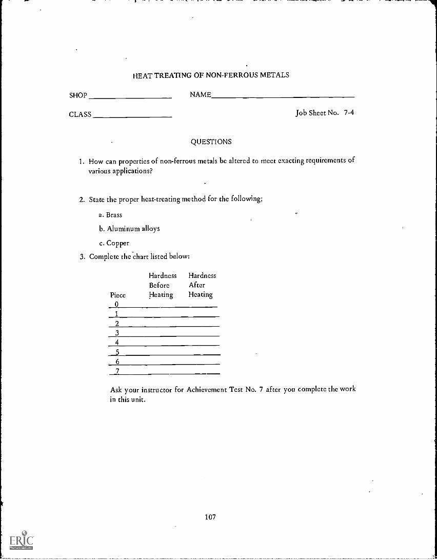
HEAT TREATING OF NON-FERROUS METALS
SHOP NAME
CLASS Job Sheet No. 7-4
QUESTIONS
1. How can properties of non-ferrous metals be altered to meet exacting requirements ofvarious applications?
2. State the proper heat-treating method for the following;
a. Brass
b. Aluminum alloys
c. Copper
3. Complete the chart listed below:
Hardness HardnessBefore After
Piece Heating Heating0
1
2
3
4
5
6
7
Ask your instructor for Achievement Test No. 7 after you complete the workin this unit.
107

THE ALLOY STEELS
DEFINITION AND TYPES
Strength of Materials Machinists Unit VIII Information Sheet No. 1
OBJECTIVE:To learn what is meant by alloy steels.
RELATED INFORMATION:All steels are alloy steels when you consider that they contain at least two
elements, iron and carbon. The term alloy, as it is used in the industrial world, is applied tothose steels containing at least one other element besides iron and carbon. The quality ofthe steel is made according to the proportions called for in the specifications set up by thedifferent steel societies.(SAE Society of Automotive Engineers; ASTM American Society of Testing Materials;AISI American Iron and Steel Institute).
The principal alloying elements that combine with steel arc nickel,chromium, manganese, tungsten, molybdenum, vanadium, and silicon. Often, two or moreare required to give the steel the desired grade for use in construction. Therefore, if you heara steel labelled ternary (three major elements) or quartcrnary (four major elements), youknow that in the former case it may be nickel steel or the latter, chromium-vanadium steel.Also, the name given the alloy is taken from the main alloying clement, such as when nickelis added to iron and carbon, it is called nickel steel.
With the demand for high-grade steels in recent years, research work andmaintenance of specifications by the steel manufacturers have been of prime importance.Where years ago the yardstick for measuring a good steel was how well a metal couldwithstand hard use, today the large steel plant has specially equipped laboratories fortesting and improving steel materials.
By alloying elements, two effects on steel are noticed. They arc:
1. Addition of third element to iron and carbon can result in a change in itsproperties.
2. Alloying elements may necessitate great changes in heat-treatment.
With the addition of small amounts of other elements, iron and carbon ivelcome a long way from the stage where heat-treating was the only method of improving st el.
Know your steels and use them wisely if you want to become tomorrow'sbetter informed machinist.
108

DEFINITION AND TYPES
SHOP NAME
CLASS INFORMATION SHEET NO. 8-1
QUESTIONS
1. What is an alloy steel?
2. Who has set up the steel qualifications or specifications?
3. Name some of the principal alloying elements that combine with iron and carbon.
4. Identify each of the following alloys as ternary or quaternary steels:a. Vanadium steelb. Nickel steelc. Silico - manganese steeld. Tungsten steele. Nickel-chromium steel
5. What was the yardstick, years ago, for meawrins a good steel?
6. How different is the present practice of judging a good steel? Explain.. .
7. What two effects are produced by the alloying of steels?
8. How do the alloys get their names?
109
THE ALLOY STEELS
CLASSIFICATION
Strength of Materials Machinists Unit VIII Information Sheet No. 2
OBJECTIVE:To learn how alloyed steels are classified.
RELATED INFORMATION:As you have learned in a previous unit, the need for standard types of alloys
was brought about by demand. The steel makers and societies put together data sheetsspecifying the exact composition of the steel alloy. This procedure gave the machinist orengineering department an easier selection of the material required to do the job.
If you look at the chart that follows, you will find the first digit or numbershows the type of steel; the second number gives the approximate percentage of alloyingmetal, and the remaining numbers give the average carbon content. (For example, an AISI-numbered steel' 5140 would be broken down as follows: The 5 would indicate a chromiumsteel, the 1 shows approximately 1% of chromium, and the 40 means an average of .40%carbon in the composition).
The section on SAE Standard Steels in a Machinery's Handbook will giveyou the compositions, applications, and heat-treatments of the various steels.
110
1

TYPE OF STEEL NUMERALS *
Carbon Steels lxxxPlain Carbon 10xx
Free Cutting, (Screw Stock) 11xx
Manganese Steels 13xx
Nickel Steels 2xxx
3.50% Nickel 23xx
5.00% Nickel 25xx
Nickel-Chromium Steels 3xxx
1.25% Nickel, .60% Chromium 31xx
1.75% Nickel, 1.00% Chromium 32xx
3.50% Nickel, 1.50% Chromium 33xx
Corrosion-and Heat - Resisting Steels 30xxx
Molybdenum Steels 4xxx
Carbon-Molybdenum 40xx
Chromium-Molybdenum 41xx
Chromium-Nickel-Molybdenum 43xx
Nickel-Molybdenum 46xx and 48xx
Chromium Steels 5xxx
Low Chromium 51::x
Medium Chromium 52xx
Corrosion-and Heat-Resisting 51xxx
Chromium-Vanadium Steels1% Chromium
Silicon-Manganese Steels2% Silicon
6xxx61xx
9xxx92xx
* The x quantity or digit would be governed by the specification. Forexample, a nickel steel having approximately 3% nickel and .40% carbon would be indicated2340.
111
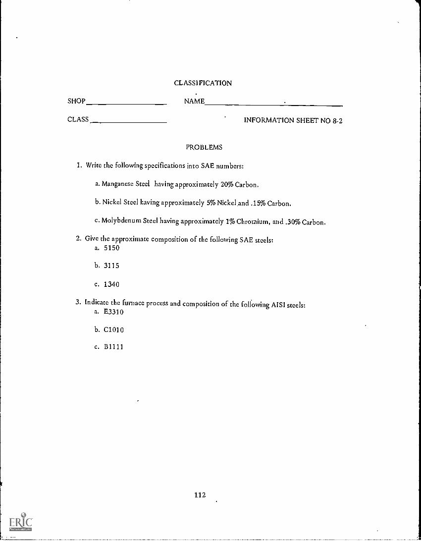
CLASSIFICATION
SHOP NAME
CLASS INFORMATION SHEET NO 8-2
PROBLEMS
1. Write the following specifications into SAE numbers:
a. Manganese Steel having approximately 20% Carbon.
b. Nickel Steel having approximately 5% Nickel,and .15% Carbon.
c. Molybdenum Steel having approximately 1% Chromium, and .30% Carbon.
2. Give the approximate composition of the following SAE steels:a. 5150
b. 3115
c. 1340
3. Indicate the furnace process and composition of the following AISI steels:a. E3310
b. C1010
c. B1111
112

THE ALLOY STEELS
COLOR CODE
Strength of Materials Machinists Unit VIII Information Sheet No. 3
OBJECTIVE:To learn how steel is coded by color.
RELATED INFORMATION:If you were to use a great athount of time trying to identify a piece of steel,
the resulting product would be priced too high for the market. To overcome this difficulty
and to help you to identify a particular steel quickly, a Steel Color Code was devised by the
National Association of Purchasing Agents using the SAE steel classification.
The method of marking bars varies according to the steel. The straight
carbon steels are painted a plain solid color on each end of the bar while the alloy steels
have a solid color identifying the alloy plus a stripe or dot giving the average carbon content.
(For example, looking at the chart that follows, SAE 1040 plain carbon steel would be
recognized by the dark red color on the bar ends).
Color Code for SAE Carbon Steels
SAE NO. Solid Color Stripe Color AE NO. Solid Color Stripe Color
1010 Yellow None 1045 Lead None
1015 Light Blue None 1046 Orange Nonc
1020 Dark Blue Nonc 1050 Brown Nonc
1025 Light Green None 1095 Tan Nonc
1030 Dark Green Nonc 1350 Red Tan
1035 Light Red None 1360 Orange Tan
1040 Dark Red Nonc 1112 White Nonc
1120 Black Nonc
Color Code for SAE Nickel Steels
SAE NO. Solid Color Stripe Color SAE NO. Solid Color Stripe Color
2315 Natural Rcd 2340 Red White
2320 Red Blue 2345 Red Brown
2325 Rcd Grccn 2350 Red Black
2330 Rcd Lcad 2512 Lead Red
2335 Red Orange
113
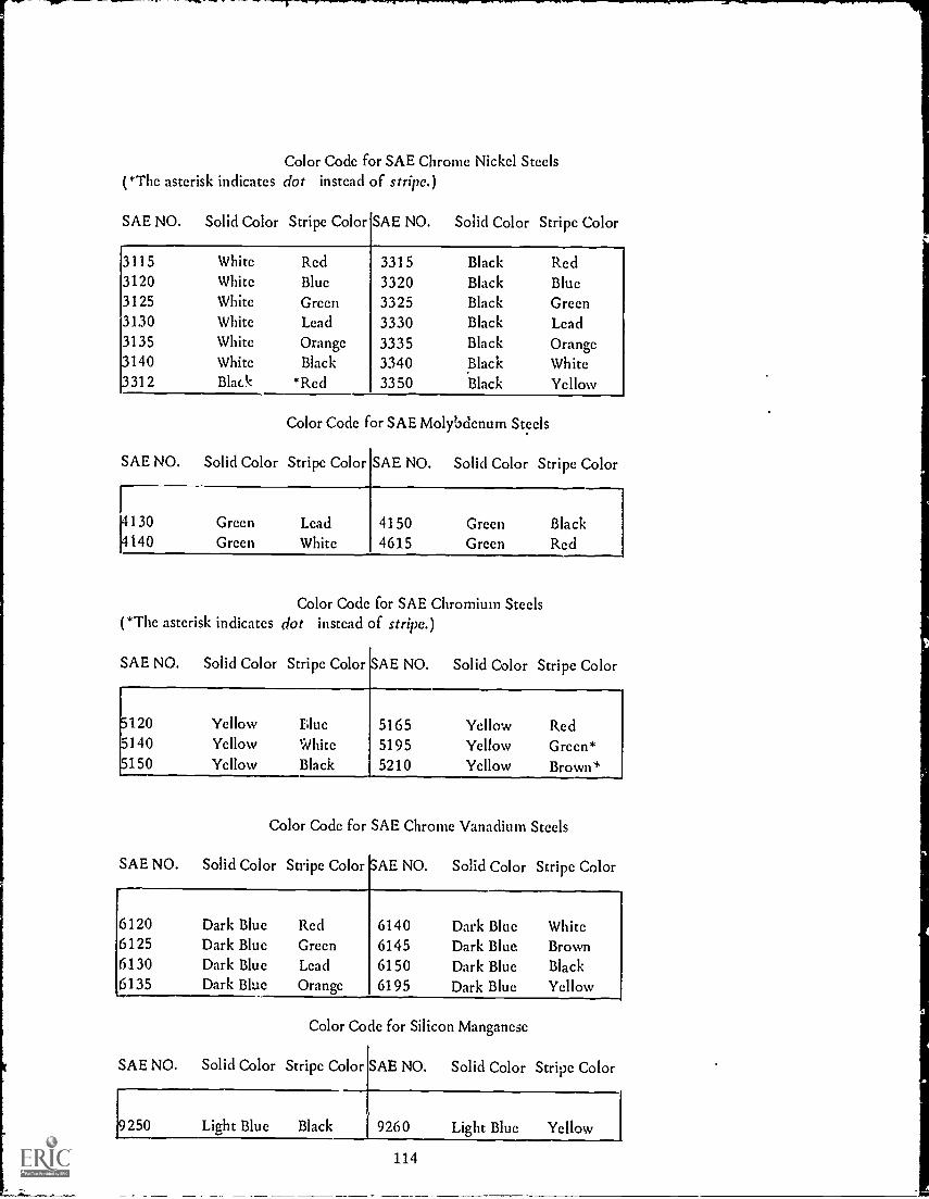
Color Code for SAE Chrome Nickel Steels(*The asterisk indicates dot instead of stripe.)
SAE NO. Solid Color Stripe Color SAE NO. Solid Color Stripe Color
3115 White Red 3315 Black Red3120 White Blue 3320 Black Blue3125 White Green 3325 Black Green3130 White Lead 3330 Black Lead3135 White Orange 3335 Black Orange3140 White Black 3340 Black White3312 Black *Red 3350 Black Yellow
Color Code for SAE Molybdenum Steels
SAE NO. Solid Color Stripe Color SAE NO. Solid Color Stripe Color
41304140
GreenGreen
LeadWhite
41504615
GreenGreen
BlackRed
Color Code for SAE Chromium Steels(*The asterisk indicates dot instead of stripe.)
SAE NO. Solid Color Stripe Color SAE NO. Solid Color Stripe Color
5120 Yellow blue 5165 Yellow Red5140 Yellow White 5195 Yellow Green*5150 Yellow Black 5210 Yellow Brown*
Color Code for SAE Chrome Vanadium Steels
SAE NO. Solid Color Stripe Color SAE NO. Solid Color Stripe Color
6120 Dark Blue Red 6140 Dark Blue White6125 Dark Blue Green 6145 Dark Blue Brown6130 Dark Blue Lead 6150 Dark Blue Black6135 Dark Blue Orange 6195 Dark Blue Yellow
Color Code for Silicon Manganese
SAE NO. Solid Color Stripe Color SAE NO. Solid Color Stripe Color
9250 Light Blue Black 9260 Light Blue Yellow
114

COLOR CODE
SHOP NAME
CLASS
PROBLEM
Give the correct color code marking for the following:
1. SAE 1010
2. SAE 1360
3. SAE 2335
4. SAE 3115
5. SAE 3350
6. SAE 4140
7. SAE 5150
8. SAE 5195
9. SAE 6125
10. SAE 6195
115
INFORMATION SHEET 8-3

THE ALLOY STEELS
ALLOYING ELEMENTS AND THEIR USE
Strength of Materials Machinists Unit VIII Information Sheet No. 4
OBJECTIVE:To learn how the alloying steels are used in the construction of machines andtools.
RELATED INFORMATION:All steels contain a certain percentage of carbon. In the SAE specifications.
the carbon steel listed in the 1 xxx division, means the product has a certain percentage ofcarbon to give it hardness. With the development of higher grades of steel for cutting tools.the carbon steels find use in bar, rod, and wire products and forgings.
Some uses of alloy steels follows:
Manganese steel is very tough, hard, and a difficult material to drill. It findsuse as jaw crushers, burglar-proof safes, and other places where design calls for this type ofsteel.
Nickel added to iron and carbon makes a steel that is tough, strong, fatigue-resisting, and rust-resisting. In the 23xx class, the steel can be rolled and forged easily and isused Lo make automobile parts, boiler plate, armor plate, and saws. The 25xx type of nickelsteel takes the place of platinum wire in light bulbs because the coefficient of expansion isthe same as glass.r,
Chromium steel is a very hard and tough material finding considerable use inbullets, armor plate, files, ball bearings, and cutting tools.
As an alloy, vanadium increases the strength of steel and refines the grain ofthe steel. Automobile parts, high-speed tools, springs. heavy -duty shafts, forgings, andcastings are uses of vandium steel.
Low-percentage silicon steels find use in springs.while those with a higherpercentage are used for electromagnets. Silicon added to steel castings increases their tensilestrength.
A high-grade steel is formed with the addition of tungsten. Lathe tools,cutters, drills, and reamers make full use of the tungsten steel.
116

ALLOYING ELEMENTS AND THEIR USE
SHOP NAME
CLASS
PROBLEM
INFORMATION SHEET NO. 8-4
Match the use of the steels with their SAE number.
a. 1070 1. Aircraft forgings
b. 2340 2. Diesel engine crankshaft
c. 9260 3. Kitchen knives
d. 52100 4. Heavy-duty shafts
e. 4140 5. Cold-rolled bar stock
f. 51335 6. Automobile spline shaft
g. 6150 7.. Leaf springs
h. 4340 8. Balls for ball bearings
117

THE ALLOY STEELS
ALLOYING EFFECTS
Strength of Materials Machinists Unit VIII Job Sheet No. 1
OBJECTIVE:
WANTED:
To learn the effects of alloying elements with steel.
Reasons for alloying steels.
RELATED INFORMATION:There are many combinations of properties that can be made by alloying
metals. If you know the properties of the alloy, then it is possible for you to use the alloy inits proper place. Greater strength, more wear resistance, and other qualities have made alloysas important as they arc with respect to pure metals in the industrial world.
Since the beginning of the 20th century, men have tried to understand andcontrol the metals and their alloys. Look into the newspaper and you will see the vastamounts being spent for metal research. The work in chemical research, fine structuralanalysis, and heat and cooling changes of metals and alloys is a daily occurrence. Theresulting knowledge is useful in the production ofmany objects that fcrrn a daily pattern inour lives. For example, stainless steel can be found replacing plated trim on automobiles orreplacing the silverware in your home.
TOOLS AND MATERIALS:Furnace, Jominy End Quench fixture, grinder, Rockwell Hardness Tester, one pieceC-1095 carbon steel, one piece deep-hardening tool steel.
PROCEDURE: (To be done in the machine shop)
1. Identify by marks each sample and measure hardness of each.
2. Heat samples to recommended quenching temperatures.
3. Remove each bar in turn from furnace and place in Jorniny End Quenchfixture.
4. After complete quenching, grind bar flat on one side. Measure Rockwellhardness each +inch. (Avoid heat by using proper coolant).
5. Record results of Rockwell tests.
118

SHOP
ALLOYING EFFECTS
NAME
CLASS JOB SHEET NO. 8-1
QUESTIONS
1. Which bar had the deepest hardness?
2. How long should the Jominy test bar remain in the cooling fixture?
3. What are two possible effects of alloying?
a.
b.
4. Is tool steel more or less expensive than other grades of steel? Why?
5. Give the maximum safe operating temperature of a high-speed tool bit.
6. Did any of the pieces crack due to the hardening operation?
7. Is corrosion resistance an important part of steel alloys? Why?
8. What is a protective coating for iron?
9. Which element has the greatest effect on improving steel's hardening ability?
10. What does red hardness mean?
Ask your instructor for Achievement Test No. 8 after you have completed this unit'swork.
119

THE PRODUCTION OF CASTINGS
CLASSIFICATION OF CASTING PROCEDURES
Strength of Materials Machinists Unit IX Information Sheet No. 1
OBJECTIVE:To learn how casting procedures are classified.
RELATED INFORMATION:
For various uses, metals and alloys must be made into articles having adefinite size and shape. These articles can be made most economically from molten metal bycasting processes.
The term casting is used when one speaks of making a solid mass of metal oralloy whose shape will not be altered or changed.
Castings are made by pouring molten metal into sand molds, into permanentmetal molds, by die casting, and centrifugal casting.
Most iron and steel castings are made in sand molds because of the difficultyin finding a metal mold material that can stand up under the high temperatures. Thepractice of using metal molds is common to the non-ferrous metal casting industries. Diecasting is limited to mass production due to the initial cost. Centrifugal casting has foundapplication in the production of large size tubing or pipe of cast iron, steel, bronze, gunmetal, nickel, monel, aluminum, and lead. This process is limited to making simple shapesthat are round or nearly round.
120

CLASSIFICATION OF CASTING PROCEDURES
SHOP NAME
CLASS
QUESTIONS
INFORMATION SHEET NO. 9-1
1. What is meant by casting?
2. Why are most iron and steel castings made in sand molds?
3. Name the various types of castings.
4. Why is the use of die casting limited?
5. Where is centrifugal casting used?
121

THE PRODUCTION OF CASTINGS
MELTING METALS FOR CASTING
Strength of Materials Machinists Unit IX Information Sheet No. 2
OBJECTIVE:To learn how the metal for making casting is incited.
RELATED INFORMATION:Metal for gray iron castings is made by melting pig iron and scrap iron in a
cupola furnace (see Fig. 1). The furnace is a vertical, round, steel structure lined withfire-clay brick. A door near the top is used to charge the furnace. The charge is made up oflayers of coke, limestone, and pig iron and scrap. Normal air is supplied through tuyeresnear the bottom of the furnace. Below the tuyere level, tap holes and spouts are used towithdraw slag and molten iron.
9x9x4N" CUPOLA BLOCKSOR STD ARCH BRICK
HIGH HEAT DUTYriRCCLAy BRICK
STD 9" STRAIGHTS9X6X4'. CUPOLA BLOCKS
CHARGINGFLOOR LEVEL
SLAG TAPPING SPOUT
Sr
8!i"
WIND 00X
TUYERCS
STD 9" STRAIGHTSTAP-OUT CLOCK
TAP TAPPING SPOUTHOLE
HEAVYMOULDING
SAND
rLigcL
INTERMEDIATEHEAT DUTY
rinecLAY BRICK
The cupola furnaceFIG. 1
122

The cupola, while efficient as an iron-melting type of furnace, does notpermit the control or changing of the metal mixture. The air furnace (reverberatory type)fired by coal, powdered coal, or oil allows modifying of the batch being melted and findsuse in making metal for malleable and alloy iron castings.
The electric-furnace melting is used when high-grade malleable and alloy ironcastings are required.
Melting for steel castings is done in small Bessemer converters, open-hearthfurnaces, or electric furnaces.
classes:In the non-ferrous foundry practice, melting furnaces are divided into two
1. Metal for casting comes in contact with the products of combustion (airreverberatory furnaces and small oil or gas fired open-hearth furnaces).
2. Metal for casting is protected from products of combustion (crucible andelectric furnaces).
Non-ferrous alloys are melted for casting without any attempt to changetheir mixture except by alloying additions. Owing to the higher cost of making non-ferrousalloyed castings, much care is taken in melting the alloys to keep the melting quality highand melting losses low.
123

MELTING METALS FOR CASTING
SHOP NAME
CLASS INFORMATION SHEET NO. 9-2
QUESTIONS
1. Name the furnaces in which each of the following gets the metal for its castings:
a. gray iron castingsb. non-ferrous alloyed castingsc. high-grade malleable castingsd. steel castings
2. Why is the air furnace used instead of the cupola furnace?
3. Why is much care taken in the non-ferrous foundry practice?
4. What charge is used in the cupola furnace?
5. Name the two classes of non-ferrous melting furnaces.
a.
b.
124

THE PRODUCTION OF CASTINGS
PATTERNS
Strength of Materials Machinists Unit IX Information Sheet No. 3
OBJECTIVE:To learn how patterns for casting are made.
RELATED INFORMATION:The first step in the production of a sand casting is to make a pattern. A
pattern is a wood or metal copy of the required article enlarged slightly to allow forshrinkage that occurs when metals cool. The allowance for shrinking of metals follows:
1. Gray cast iron per ft.
2. White cast iron and steel per ft.
3. Copper and brass per ft.
4. Lead and zinc ry per
When a quantity of small parts is to be made, they can be gated. Thepatterns are connected by channels or runners that permits the flow of the molten metal toeach of the castings. After cooling, the gates are cut off and the surface of the castingground smooth.
The woods generally used for patterns are white pint, mahogany, cherry,maple, and birch. White pint is considered the best of the woods mentioned because it canbe worked easily, takes glut and varnish and stands up fairly well under use.
Pattern wood should be well seasoned to prevent warping or shrinking.
Patterns that are to be used more than once are varnished to protect againstmoisture.
Metal patterns of brass, cast iron, aluminum or steel are made from anoriginal wood pattern and are used where constant use makes wood patterns impractical.Some companies have had success with plastic patterns instead of metal ones. The process isa little more complicated than the making of a metal pattern, but manufacturing costs havebeen cheaper with plastic.
125

PATTERNS
SHOP NAME
CLASS INFORMATION SHEET NO. 9-2
QUESTIONS
1. What is a pattern
2. Give the shrinkage allowance on patterns for the following materials:a. Steelb. Brass
3. Why is white pine considered the best wood in the making of patterns?
4. What materials are metal patterns made of?
5. Why should well-seasoned lumber be used in making patterns?
126

THE PRODUCTION OF CASTINGS
SAND CASTING
Strength of Materials - Machinists Unit IX Job Sheet No. 1
OBJECTIVE:
WANTED:
To learn how a sand casting is made in a mold.
Steps in making a sand casting.
RELATED INFORMATION:
Sand casting is used to eliminate the high costof machining an object to specified sizes. It is usuallydone when a job is too complicated to machine or thenumber of parts is so great that it is cheaper to cast.The machinist's work consists of finishing the object.
GATE RISER
.
SPRUE,
COPE
DRAG
CROSS-SECTION SAND CAST MOLD
TOOLS AND MATERIALS:Molding flask, green sand, parting sand, moldboard, wood pattern, lead, rammingtools.
PROCEDURE:
1. Place drag part of pattern, bottom side up, on moldboard.
2. Surround with drag of flask.
3. Ram green sand between pattern and flask.
4. Place bottom board over drag and invert.
5. Put cope of pattern on top of drag pattern and surround with cope of flask.Connect cope and drag of flask.
6. Sprinkle parting sand around over drag area.
127

7. Ram green sand between flask and pattern.
8. Provide for gate and riser and any other vent holes.
9. Break flask into its two parts and remove pattern. Remove loose sand.
10. Close flask and start pouring lead into gate. (Lead is used because of lowmelting point).
11. Allow to cool.
19. Break open flask to see result of pattern.
13. Students record results of experiment, noting procedures. casting defects,etc.
14. Students should ask any questions on procedures that were not clear.
128

SAND CASTING
SHOP NAME
CLASS JOB SHEET NO. 9-1
QUESTIONS
1. Why are sand castings used?
2. Which part of the flask is the drag?
3. Which part of the flask is the cope?
4. Why is the pattern split?
5. Explain the use of parting sand.
6. Why is green sand used?
7. Give the reasons for using a gate and riser.
8. What wood was used in the pattern? Why ?
129

THE PRODUCTION OF CASTINGS
METAL MOLDING
Strength of Materials Machinists Unit IX Information Sheet No. 4
OBJECTIVE:To learn how castings are made in a metal mold.
RELATED INFORMATION:
When a large number of the same metal part is to be made by casting, it isbetter to carry out the operation in permanent metal molds.These molds can be used overand over again, thus doing away with the work of rebuildingor repairing the sand molds foreach casting.
Owing to the high temperatures that occur for iron and steel castings, it isdifficult to find a permanent mold material.
On the other hand, non-ferrous alloys are cast in metal molds, makingsounder, cleaner castings with very good mechanical properties.
Permanent metal molds consist of two cast-iron halves with the partingsurface arranged in a vertical direction. Openings in metal mold castings are made by usingsteel or sand cores. In some cases slightly tapered steel cores pass through the mold wall.They can b. removed independently of the operation of the mold.
The molten metal flows into the permanent mold under the force of gravity.The .mold is vented to permit the escape of gases and has risers to feed metal to the casting.
Owing to their higher thermal conductivity (rate at which heat passesthrough a metal) castings become solid and cool much more quickly in metal molds than insand molds.
130

METAL MOLDING
SHOP NAME
CLASS INFORMATION SHEET NO. 9-4
QUESTIONS
1. When are metal molds used? Why?
2. Why is it difficult to find permanent mold materials for iron and steel castings?
3. Give some reasons for using metal molds in the casting of non-ferrous alloys.
4. Is making castings in a metal mold the same as in a sand casting? Explain.
5. What do you mean by high thermal conductivity?
131
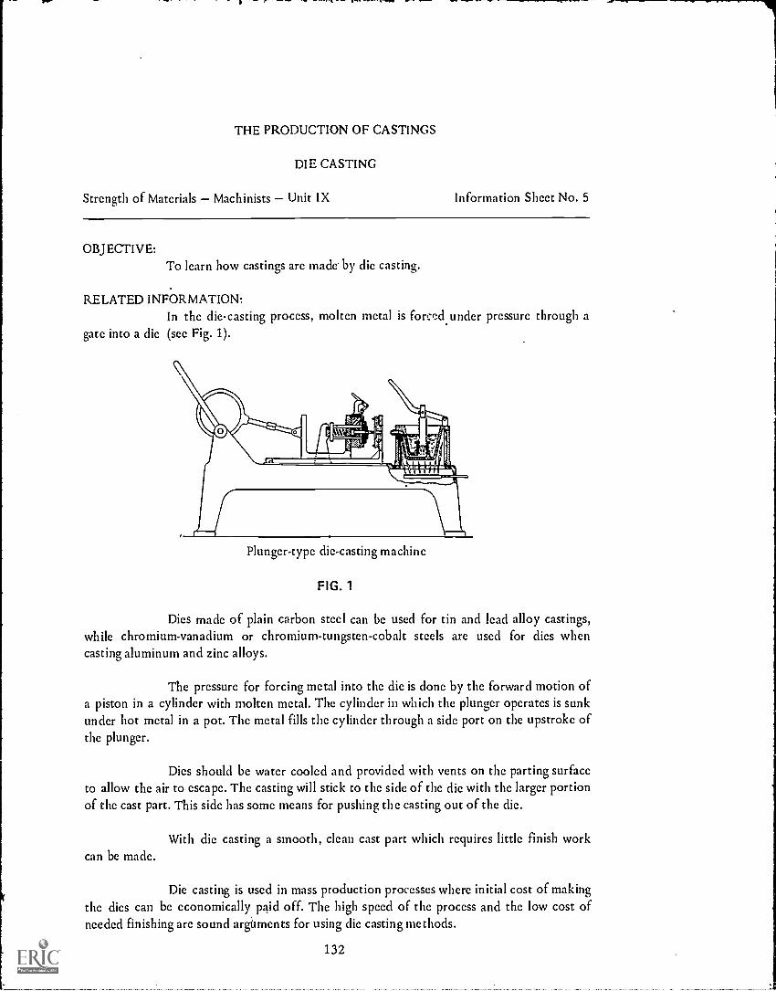
THE PRODUCTION OF CASTINGS
DIE CASTING
Strength of Materials Machinists Unit IX Information Sheet No. 5
OBJECTIVE:To learn how castings are made' by die casting.
RELATED INFORMATION:In the die-casting process, molten metal is forced under pressure through a
gate into a die (see Fig. 1).
Plunger-type die-casting machine
FIG. 1
Dies made of plain carbon steel can be used for tin and lead alloy castings,while chromium-vanadium or chromium-tungsten-cobalt steels are used for dies whencasting aluminum and zinc alloys.
The pressure for forcing metal into the die is done by the forward motion ofa piston in a cylinder with molten metal. The cylinder in which the plunger operates is sunkunder hot metal in a pot. The metal fills the cylinder through a side port on the upstroke ofthe plunger.
Dies should be water cooled and provided with vents on the parting surfaceto allow the air to escape. The casting will stick to the side of the die with the larger portionof the cast part. This side has some means for pushing the casting out of the die.
With die casting a smooth, clean cast part which requires little finish workcan be made.
Die casting is used in mass production processes where initial cost of makingthe dies can be economically, paid off. The high speed of the process and the low cost ofneeded finishing are sound arguments for using die casting methods.
132

DIE CASTING
SHOP NAME
CLASS
QUESTIONS
INFORMATION SHEET NO. 9-5
1. What type of steel is used in the dies for making tin and lead alloy castings?
2. What type of steel is used in the dies for making aluminum and zinc alloy castings?
3. Give the advantages of die casting.
a.
'b.
4. State the disadvantage of die casting.
133
THE PRODUCTION OF CASTINGS
CENTRIFUGAL CASTING
Strength of Materials Machinists Unit IX Information Sheet No. 6
OBJECTIVE:To learn how simple round or nearly round shapes are made by centrifugalcasting.
RELATED INFORMATION:The centrifugal casting machine consists of a refractory or metal round mold
which turns at,speeds up to 10,000 rpm (revolutions per minute).
Pouring spouts are provided at one or both ends of the mold. The metal fedto the mold is watched very carefully in order to maintain an even flow of material. Thepressure on the metal due to the force of the circular motion gives a more dense, finer-grainstructure, and better mechanical properties than in sand casting.
The metal nearest the center of the rotating axis of the round mold gives thesame results as the metal in the gates and risers of the sand castings. This layer, which isporous and has a large amount of impurities, can be machined from the inner surface of thecasting.
The principal users of centrifugal castings have been the large-size pipe andtubing industries. The castings are made in many different types of metals.
134

CENTRIFUGAL CASTING
SHOP NAME
CLASS INFORMATION SHEET NO. 9-6
QUESTIONS
1. Where is centrifugal casting used?
2. Give some reason for making this type of casting.
3. What does the centrifugal casting machine consist of?
135

THE PRODUCTION OF CASTINGS
DEFECTS IN CASTINGS
Strength of Materials Machinists Unit IX Job Sheet No. 2
OBJECTIVE:
WANTED:
To learn what defects to look for in castings.
Results of examination of castings.
RELATED INFORMATION:It is safe to say that a perfect casting has yet to be made, but ones that are
being produced are reasonably free from defects. The principal defects are:1. Rounded-off edges 4. Blowholes2. Cooling cracks 5. Pinholes3. Shrinkage cracks 6. Shrinkage cavities
Cooling cracks are found in brittle alloyed castings such as cast iron. Theyare caused when stresses develop due to different rates of cooling in the casting.
Shrinkage cracks develop during high temperatures mostly in non-ferrousalloys. Certain regions of the casting remain in the liquid state and can be ruptured or splitwith very little force.
Shrinkage cavities occur when proper design is not followed. These cavitiesshould form outside of the casting in the gates.
Blowholes (larger than pinholes) result from trapped air due to improperventing and feeding, or from gases resulting in casting.
Pinholes come from.trapped gas coming out of solution during the time thecasting is becoming solid.
There are several methods used in industry to discover defects in castings.They are the X-Ray inspections for not too thick sections, the radio-graphic method forheavier sections, and the magnaflux method.
The magnaflux method reveals surface or near-surface cracks in steel. Thesurface of a casting is covered with suspended fine iron or magnetite powder, after or whilebeing magnetized. Cracks are shown by local clusters of the powder.
136

TOOLS AND MATERIALS:Hacksaw; iron, steel and brass castings.
PROCEDURE: (To be done in the machine shop)1. Examine the surface of he castings for defects.
2. Cut castings in half with hacksaw.
3. Examine castings for defects.
4. Note your results.

SHOP
DEFECTS IN CASTINGS
NAME
CLASS JOB SHEET NO. 9-2
QUESTIONS
1. What arc the principal defects found in castings:a.
b.c.d.
c.12
2. How does industry discover these defects?a.b.c.
3. Explain the defects found on the surface of sample castings.
4. What defects did you find on the inside of the castings? Explain.
Ask your instructor for Achievement Test No. 9 after you have completed this unit's work.
138

NON-FERROUS ALLOYS
COPPER
Strength of Materials Machinists Unit X Information Sheet No. I
OBJECTIVE:To learn the non-ferrous alloys of copper and how they are used.
RELATED INFORMATION:Steel is not the only alloying metal. There are a number of combinations of
elements in the non-ferrous metals which make them important non-ferrous alloys.
Copper is alloyed with several different metals because the resulting mixtureis stronger and harder than pure copper, easier to cast and machine, has greater corrosionresistance, higher elastic nature, and is cheaper.
While annealing is the only method used to heat-treat pure copper, othertypes of treatments besides annealing are used with some of the copper alloys. For example.the alpha brasses (gilding metal, low brass, yellow brass, etc.) are annealed aftercold-working, while on aluminum-bronze, a solution and precipitation type treatment isused.
Copper alloys can be divided into two main classes: the brasses (alloys ofcopper and zinc) and the bronzes (alloys of copper and tin). A note of caution should befollowed when specifying these materials because terms of the brass industry are misleading.
For example, the term commercial bronze may be used when referring tosome compositions of copper-zinc.
With a range of 5 to 45 percent of zinc, the brasses are among the mostuseful alloys. A chart of their composition, use, and properties follows.
139

COMPOSITION, USES, AND PROPERTIES OF BRASSES
NAME
Composi-tion To
COLOR TYPICAL USES TEMPER
Tensilestrength
psi
Elonga-don in2 in..
%Cu Zn
Muntzmetal
59 41 Reddish Architectural work,welding rod, con-
Hot-rolled
54,000 45
denser, tubes,valve stems
Cold-rolled
80,000 5
1 Extrud-ed rivetmetal
63 37
\Rivets, screws Rivdt 60,000 30
.
-,,--x,..
Highbrass
66 34 Typicalbrasscolor
Stamping, Blank-ing, drawing,spinning, forming,radiator cores,springs, screws,
LightannealSoftannealHard
53,000
46,000
76,000
54
64
7i rivets, grill Rivet 60,000 30
work, chains Spring 125,000
Cart-ridge orspinningbrass
70 30 Cartridges, eye-lets, tubes,spinning, drawing
LightannealSoftanneal
53,000
46,000
54
64
Hard 76,000Spring 92,000 3
Brazingbrass
75 25 Drawing, spinning,springs; particular-
Lightanneal
52,000 50
ly suited forbrazing
Softanneal
45,000 62
Hard 76,0U0 7Spring 125,000
Lowbrass
80 20 Redgold
Drawing, forming,flexible hose
Lightanneal
47,000 47
Softanneal
43,000 55
Hard 75,000 7
Spring 120,000
140

COMPOSITION, USES, AND PROPERTIES OF BRASSES
NAME
Composi-tion %
COLOR TYPICAL USES TEMPER
Tensilestrength
si
Elonga-don in2 in.,
%Cu Zn
Richlow
brass
83 17 Fourdrinicr wire Soft 42,000
Rcdbrass
85 15 Rcd Hardware, radiatorcores, plumbing
Lightanneal
45,000 48
pipe, condensertubes, flexible
Softanneal
40,000 43
hose Hard 71,000 5
Spring 83,000 3
Com-mac-ial
90 10 Bronze Screen wire,hardware, trim,forgings, screws,rivets, costume
Light...)
annealSoftanneal
41,000
38,000
42
56
Jewelry Hard 64,000 4
Spring 73,000 3
Gild-ing
metal
95 5 Copper Drawing,spinning,forming
LightannealSoftanneal
.......
35,000
36,000
42
44
Hard 55,000 4
spring 65,000 3
Looking over this list, you can sec the many varieties of uses that the copperalloys find in our daily necessities. The copper plumbing for easier and safer water supplyand the screen wire for healthier living are some examples of the improvements brought byalloys.
141
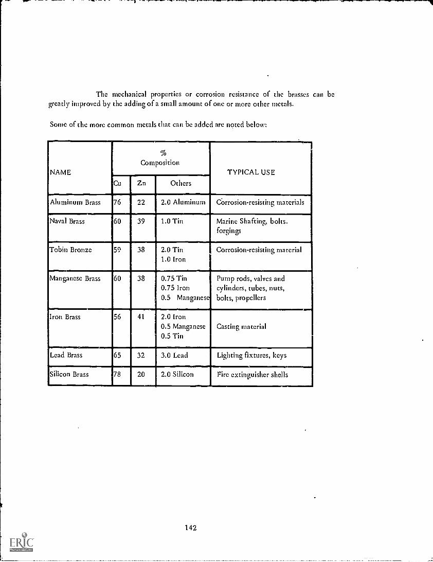
The mechanical properties or corrosion resistance of the brasses can begreatly improved by the adding of a small amount of one or more other metals.
Sonic of the more common metals that can be added are noted below:
NAME
To
CompositionTYPICAL USE
Cu Zn Others
Aluminum Brass 76 22 2.0 Aluminum Corrosion-resisting materials
Naval Brass 60 39 1.0 Tin Marine Shafting, bolts.forgings
Tobin Bronze 5, 38
..--.--......60 38
2.0 Tin1.0 Iron
Corrosion-resisting material
Manganese Brass 0.75 Tin0.75 Iron0.5 Manganese
Pump rods, valves andcylinders, tubes, nuts,bolts, propellers
Iron Brass 56 41 2.0 Iron0.5 Manganese0.5 Tin
Casting material
Lead Brass 65 32 3.0 Lead Lighting fixtures, keys
Silicon Brass 78 20 2.0 Silicon Fire extinguisher shells
142

Tin increases the strength. hardness and durability of copper to a muchgreater extent than zinc. The most useful bronzes arc those containing 8 to 11 percent oftin.
The composition and use of the bronzes follow:
NAME
% Composition
TYPICAL USECu Tin Others
Bell metal 80 20 Bells and gongs
Speculum metal 66 34 Mirrors and reflectors
Phosphor bronze 92 8 .05 Phosphorus Springs. bearings, weldingrod
caring bronze 75 10 15.0 Lead Heavy load bearings
luminumronze
88 0.5 8.0 Aluminum3.0 Iron
Ccindenser tubes and giftarticles
Silicon bronze 96 0.5 3.5 Silicon Tanks, bolts and chain
cryllium bronze 98 2.0 Beryllium Springs and cutting tools
There are several copper-nickel alloys that are known as manganin, aresistance wire with very low temperature coefficient of resistance, composed of 80%copper, 5% nickel, and 15% manganese, and nickel or German silvers containing 65%copper, 20% zinc, and 15% nickel,which are used as the base metal for plated silverware andthe metal for high-grade plumbing and hardware.
143

COPPER
SHOP NAME
CLASS INFORMATION SHEET NO. 10-1
QUESTIONS
1. Why is copper alloyed with other metals?
2. Name the three classes of copper alloys.a.b.c.
3. How can the mechanical properties or corrosion - resistance of the brasses beimproved?
4. Why is tin alloyed with copper?
5. Give typical uses of the following:a. Naval brassb. Silicon bronzec. Speculum metald. Muntz metale. Gilding metalf. Beryllium copperg. Manganin
144

NON-FERROUS ALLOYS
ALUMINUM
Strength of Materials - Machinists Unit X Information Sheet No. 2
OBJECTIVE:
To learn the non-ferrous alloys of aluminum and how they arc used.
RELATED INFORMATION:
Over 50% of the aluminum produced is used in the alloy form. The aircraftindustries gave an increased rise to the development because of the light weight, althoughrecent trends show the automobile, railroad and building fields making more and more useof the material.
The aluminum alloys can be divided into two classes: casting (cast in eithersand or permanent molds) and wrought (mechanically shaped or formed) alloys.
Some of the cast and wrought alloys along with their composition and useare listed below:
DESIGNATION
CAST ALLOYS
% COMPOSITION USE
SAE 33 90 Aluminum8 Copper1 Silicon1 Iron
General castingalloy
SAE 38 96 Aluminum4 Copper
High strength, heat-treated casting
SAE 322-1 93.5 Aluminum1 Copper5 Silicon
0.5 Manganese
Liquid-cooledcylinder heads
Alcoa 195 T 6 96 Aluminum4 Copper
Aircraft, marine, busand engine parts
145

DESIGNATION
WROUGHT ALLOYS
% COMPOSITION' USEISAE 25 99 Aluminum Cooking utensils
SAE 29 97 Aluminum1.5 Manganese.2 Copper
Sheet metal work
.SAE 26(Duralumin)
92 Aluminum1 Manganese
4.5 Copper.5 Magnesium
Strong alloy.Structural shapes,bolts and nuts, screws,rivets, forgings
SAE 24 92 Aluminum4.5 Copper1.5 Magnesium.5 Manganese
Aircraft con.,truction
The softer grades of aluminum alloys are more difficult to machine than theharder alloys. Greater rake and clearance angle on cutting tools,and kerosene or mixtures ofkerosene and lard oil are used when machining aluminum alloys.
* Approximate
146

SHOP
CLASS
ALUMINUM
NAME
INFORMATION SHEET NO. 10-2
QUESTIONS
1. Why is aluminum used in the aircraft industry?
2. Name the types of aluminum alloys.
3. Give the use of the following alloys:a. SAE 24b. SAE 29c. SAE 33d. SAE 322-1
4. Describe cutting-tool use and lubricant called for in the machining of aluminumalloy.
147

NON-FERROUS ALLOYS
MAGNESIUM
Strength of Materials Machinists Unit X Information Sheet No. 3
OBJECTIVE:To learn the non-ferrous alloys of magnesium and how they.are used.
RELATED INFORMATION:Magnesium alloys are second in importance to the aluminum alloys as light
structural material. The most outstanding of the light magnesum alloys is the range soldunder the trade name Dow Metal.
TYPE
The outstanding characteristics of Dow Metal are:
1. Extreme lightness (-3- as heavy as aluminum alloys).
2. Tensile strength from 18,000 to 35,000 psi.
3. Forged and extruded parts do not require heat treatment.
4. Easily machined.
5. Good corrosion resistance except when exposed to salt water and iron.
Some of the types, compositions, and uses of magnesium alloys are:
COMPOSITION USESAE 500 90.8 Magnesium
6.0 Aluminum.2 Manganese
3.0 Zinc
Sand castings
SAE 501 90.2 Magnesium9.0 Aluminum0.2 Manganese0.6 Zinc
Die castings
148

TYPE % COMPOSITION USE
SAE 520 or 521 93 to 94 Magnesium3 to 6 Aluminum0.2 Manganese
1 to 3 Zinc
Structural shapes.tubing. rods. bars
SAE 51 98.5 Magnesium1.5 Manganese
Rolled plate. sheetor strips
DOW J, L, M, 0 or X 91 to 94 Magnesium
3 to 9 Aluminum.2 Manganese
1 to 3 Zinc(L has tin or cadmiuminstead of zinc)
Press and
hammered
forgings
---L
149

MAGNESIUM
SHOP NAME
CLASS INFORMATION SHEET NO. 10-3
QUESTIONS
1. How do magnesium alloys rate?
2. Give the outstanding characteristics of Dow Metal.
3. Give use of each of the following alloys:a. SAE 51b. SAE 501
4. How can magnesium alloys be machined without lubricants?
150

NON-FERROUS ALLOYS
ALUMINUM AND MAGNESIUM
Strength of Materials Machinists Unit X Job Sheet No. 1
OBJECTIVE:
WANTED:
To sec how aluminum and magnesium alloys can be machined.
Results of machining the alloys.
TOOLS AND MATERIALS:Lathe, Bar stock of Alcoa 11sT3 and Dow Chemical Co. J.
PROCEDURE: (To be done in machine shop by instructor)1. Set up aluminum alloy in lathe.
2. Show comparison of cutting tool with one normally used on steel.
3. Make cut on stock,explaining lubricant used and any precautions necessary.
4. Have students record the information.
5. Set up magnesium alloy in lathe.
6. .Make cut and explain precautions to students.
7. Have students record the information.
151

NON-FERROUS ALLOYS
NICKEL
Strength of Materials Machinists Unit X Job Sheet No. 2
OBJECTIVE:
WANTED:
To learn the non-ferrous alloys of nickel and their uses.
Differences in the various nickel alloys.
RELATED INFORMATION:The nickel-copper alloys have been explained, but the use of a great
percentage of nickel gives us some very good alloys.
A most important alloy containing 67% nickel, 28% copper and theremainder of the mixture iron with a small amount of manganese, silicon, and carbon isMonel metal. It has great corrosion resistance and is used in dye vats, sinks, hot waterboilers, and kitchen equipment.
Heat-resisting and electrical - resistance alloys are named nichrome andchrome'. They contain about 62% nickel, 15% chromium, and the remainder iron with smallamounts of carbon.
The low - thermal expansion alloys are the Invar or iron-nickel alloyscontaining about 30 to 40% nickel. Measuring tapes, instruments, watches and struts foraluminum-alloy pistons are important uses of this alloy.
Finally, the magnetic alloys containing iron, nickel, and sometimes cobalt invarying amounts, find use as permanent magnets.
TOOLS AND MATERIALS:Pieces of brass, bronze, Monel metal, nichrome, Invar, Alnico, steel, file, microscope,furnace, electrical leads.
PROCEDURE: (To be done in machine shop by instructor)
1. Test each of the pieces of metal to see if they will attract the piece of steel. Havestudents record results.
2. File each piece and collect filings. Be sure file is clean after each sampling.
3. Observe filings under microscope. Have students record their observations.
4. Show low thermal expansion of Invar. Have students record results.
5. Show the heat-resisting and electrical resistance of nichrome. Have students recordresults.
152

NON-FERROUS ALLOYS
SOLDERS AND BRAZING
Strength of Materials Machinists Unit X Job Sheet No. 3
OBJECTIVE:
WANTED:
To learn of alloys that can be used to join surfaces of metal.
Results of soldering materials.
RELATED INFORMATION:Solder is an easy-melting alloy used to join the surfaces of metals, while the
brazing alloy has a higher melting point than the lead-tin solder, yet melts below the meltingpoint of the metals being joined.
The flux (gathers up or dissolves oxide or other matter on the surface ofmetal) for solder is zinc chloride and for brazing is a mixture of borax and boric acid.
Brazing has been to a large extent taken over by welding practices because ofstronger adhesion (sticking together) of the metal by the latter method.
TOOLS AND MATERIALS:Soldering iron, solder, acid or soldering paste, two pieces of clean sheets of copper.
PROCEDURE:
1. Heat iron.
2. Place acid or paste on parts of copper to be fastened together.
3. Lap pieces of copper, making the coated pieces face each other.
4. Solder along joints.
5. Allow to cool and test results.
6. Record your observations as to strength of joints, how solder was melted, amount ofsolder used, etc.
153

NON-FERROUS ALLOYS
BEARING METALS
Strength of Materials Machinists Unit X Information Sheet No. 4
OBJECTIVE:To learn the use and composition of bearing metals.
RELATED INFORMATION:Since there is much wear on machinery, a metal had to be made that could
be soft enough to mold itself about a shaft,with good resistance to wear. The requirementhas been attained by use of an alloy containing hard grains in a soft natural material. Thisstructure is found in the white alloys (lead, tin, antimony, copper).
Most popular of the white alloys is "Babbitt metal" which is expensivebecause of the large amount of tin used as the hard-grain part of the alloy, but gives betterservice because of the make-up of the alloy.
The bronzes to which a large amount of lead has been added are used asbearing metals, too. But their composition differs, in that they are made up of soft grains ina hard natural material. The leaded bronzes are of poorer quality than the white alloysbecause they do not give or mold about the shaft as well.
A new type of bearing material is a porous self-lubricating type consisting ofbronze alloys. Porous bearing alloys can soak up large amounts of oil. This oil is held in thepores of the bearing metal. until pressure causes it to flow out onto the surfaces of thebearing. Thus, the term, self-lubricating.
Bearing metals find many uses in bearings that are used in the industrialworld in various ways.
154

BEARING METALS
SHOP NAME.............
CLASS INFORMATION SHEET NO. 10-4
QUESTIONS
1. How do white alloys differ from the leaded bronzes as a bearing metal?
2. Give the composition of each of the bearing metals.
3. How does the self- lubricating bearing get its name?
4. Give some examples of where bearing metals arc used in the machine shop.
Ask your instructor for Achievement Test No. 10 after you have completed this unit'swork.
155

THE STRUCTURE OF METALS
CRYSTALS AND THEIR FORMATION
Strength of Materials Machinists Unit XI Information Sheet No. 1
OBJECTIVE:To learn the crystal formation of metals.
RELATED INFORMATION:As you have learned, metals raving strength together with an ability to
deform without rupture are of great importanct. '.,1 the mechanical and structural field. Inaddition, the many other physical and mechanical pm,ncrties have a bearing on the structureof metals.
The structure of metals depends on two characteristics:1. How the atoms are composed.2. How the atoms are arranged.
When a metal changes from a liquid to a solid state, it crystallizes. (See Fig. 1)
ENLARGED VIEW OF CRYSTAL STRUCTURE
FIG. 1
During the process of becoming solid, the atoms of the liquid metal arrangethemselves, forming a definite space pattern. The pattern formed is known as the spacelattice (see Fig. 2)
156

You will notice it is a series of points in spaceformed in a variety of geometrical patterns. The oneshown in Fig. 2 is a simple arrangement.
FIG. 3
To help you see the change from a molten state toa crystal formation, it will be shown to you step bystep. A crystal seed forms as shown in Fig. 4.
FIG. 5
FIG. 2
Akhough the atoms are too smallto be seen by the eye. the space-latticediagram has been determined byX-Ray crystal -analysis methods. Thismethod has shown the cut, pattern(Fig. 2) to be the crystal structure ofcopper, iron, aluminum, lead, nickel,_etc. Some of the metals assume thebody-centered cubic pattern, see Fig.3. There are many formations of themetals which can be found in books-on metallurgy.
O
FIG. 4
The seed proceeds to send outshoots (see Fig. 5) forming a skeletonof a crystal in much the same wayfrost forms a pattern. Atoms attachthemselves to the axis of the growingcrystal one layer on top of another.
Finally, the completed solid or crystal is formedas shown in Fig. 6. The nature of the crystal border isstill unknown, but it is assumed it is an interlockingborder line.
FIG. 6
The external shape of the crystal is contro...a by the conditions leading toits formation. The crystals found in all commercial metals and alloys are called grainsbecause of their variety of external shapes. A grain would be a crystal having any variety ofexternal shape, but having an internal atomic structure based upon the space lattice withwhich it is born.
1 57

CRYSTALS AND THEIR FORMATION
SHOP NAME
CLASS INFORMATION SHEET NO. 114
QUESTIONS
1. Name two characteristics upon which the structure of metal depends.a.b.
2. Define grain.
3. Make a sketch of a simple cubical space lattice structure.
4. How can a space lattice diagram be determined?
5. Sketch the three steps in the growth of a crystal.
158

THE STRUCTURE OF METALS
GRAIN STRUCTURE
Strength of Materials Machinists Unit XI Job Sheet No. 1
OBJECTIVE:
WANTED:
To investigate the grain structure of various metals.
Observations as to the difference in grain structures of metals.
TOOLS AND MATERIALS:Microscope, heat-treating furnace, quenching bath, cast iron, mild steel,wrought iron.
PROCEDURE: (To be demonstrated by the machine shop instructor)
1. Fracture metals and examine structure under inicroscope.
2. Heat each of the metals to above the critical range and fast-cool. Fracture and observegrain structure under microscope.
3. Instructor will explain change that has taken place.
159

THE STRUCTURE OF METALS
DEFORMATION OF METALS
Strength of Materials Machinists Unit XI Job Sheet No. 2
OBJECTIVE:
WANTED:
To learn what takes place when metals are deformed.
Results of deformation.
RELATED INFORMATION:Knowing that metals are composed of many crystals or grains, you must be
able to see what happens when a piece of metal is bent, drawn or forged. When a forceexceeding the elastic limit is applied to the metal, the crystals of the metal start to getlonger by an action of slipping,which takes place within and between adjacent crystals. Tounderstand this reaction a little more, get a deck of cards. Having set them up in an evenpile, give one end a shove. The sliding between the individual cards occurs in somewhat thesame way as the crystals in metals.
FIG. 1
Deformation is illustrated in Figs. 1 and 2.
Commercially Pure Iron beforeDeformation
Commercially Purc Iron after
Slight Plastic Deformation
FIG. 2
Notice the dark lines within the grains in the deformed iron. You can noticea 'very deformed piece of metal because of these long crystals.
A permanently deformed metal undergoes the following changes in itsphysical properties:
1. Increased tensile strength and hardness.2. Stiffness and machining,remains about the same.3. Ability to shape is reduced.
Continued deforming of the metal causes it to become brittle.
160

TOOLS AND MATERIALS:Piece of x 4" x 4" steel with two 4" diameter holes, vise, furnace, two pieces of
wrought iron, hammer, anvil, tongs.
PROCEDURE: (To be done in the machine shop)
1. Place i " steel in vise with center of holes along top of vise jaws.
2. Bend metal 90°, being careful not to strike holes.
3. Remove piece of steel from vise and note how holes look on inside andoutside of bend. Record results.
4. Heat pieces of iron in furnace.
5. Withdraw pieces of bright red iron from furnace, lap ends on anvil andquickly beat together. Did deformation take place? Record results.
Ask your instructor for Achievement Sheet No. 11 after you have completed thisunit's work.
161

SIMPLE STRESS
UNIT STRESSUNIT STRAIN
Strength of Materials Machinists Unit XII Information Sheet No.'1
OBJECTIVE:To learn what is meant by unit stress and how it is used.
RELATED INFORMATION:Imagine that a square steel rod of 2 inches x 2
inches (Fig. 1) is put into the jaws of a testingmachine. The force needed to break the bar wasrecorded as 200.000 lbs.
50,000 #
50,000#
FIG. 2
200,000#
200,000#
FIG. 1
2" x 2"STEEL ROD
Fig. 2 is a bar of the same kind ofsteel, but, as you notice, onlymeasures 1 inch x 1 inch. The forceneeded to break this bar is 50,000 lbs.,or one-fourth. This result is obtainedbecause the area that resists the pull isonly one-fourth of that of the 2 inchx 2 inch bar.
The length of the bar has no effect on the breaking load. The cross-sectionalarea and type of material are the factors ro take into consideration when you are looking forthe resisting force of the material. Mathematically, the set-up appears thusly:
Resistance (R)Total Force (F)
Cross-Section Area (A)
162
The resistance .of one square inch of the resisting area is called the unit stressand is measured in terms of pounds per square inch (psi).
For example, the unit stress for the 2,inch x 2 inch steel rod in Fig..1 wouldbe solved thusly:
R .,F 200,000A 2x 2 50,000 psi. (172)
The unit strain on the other hand is the deformation per unit of length dueto a certain load. When a steel rod gets longer without breaking, each inch of the length willstretch or deform an equal amount to make up the total.
in inches, or:To find unit strain, divide the total strain in inches by the length of the body
Unit strain (D) =Total strain (S)Length of body (L)
Unit strain is measured in terms of inch per inch.
An example of unit strain would be suspending a weighted object from awire, causing it to stretch or get longer. If the amount of stretch was 0.005 inches and theoriginal length was 50 inches, the strain would be solved thusly:
= =.00S
D L 505
.001 in. /in.
163

UNIT STRESSUNIT STRAIN
SHOP NAME
CLASS INFORMATION SHEET NO. 12-1
PROBLEMS
1. Find the unit stress for al-square-inch rod having a load of 50,000 lbs.
2. Find the unit strain for a piece of wire that is 25 inches long and stretched 0.0025inches when a load was applied.
3. Solve the unit stress for a 1 inch x 2 inch steel bar supporting a load of 60,000 lbs.
4. What is the unit strain for a piece of material that stretched 0.005 inches when a loadwas applied to a wire that was 75 inches long?
5. A 2-inch-diameter steel cable 74 inches long has a 40,000 lbs. weight attached to it.The steel cable was measured again and found to be 8 inches long. Find the unit stressand milt strain.
164

SIMPLE STRESS
TENSION
Strength of Materials Machinists Unit XII Job Sheet No. 1
OBJECTI VE:
WANTED:
To learn when an object is in tension.
Conclusion as to when an object is ih tension.
RELATED INFORMATION:The wire rope used to tow cars has to resist the pull of the wrecker and the
car being towed. The action of the two cars or forces, which is equal and in oppositedirections, causes the wire rope to get longer. This condition is known as tension.
MATERIALS:Tension apparatus, steel and copper wire.
PROCEDURE:1. Set up apparatus with the steel wire.
2. Indicator should be at zero.
3. Turn crank one revolution. Observe weight on indicator.
4. Continue turning handle until wire breaks.
5. Record weight.
6. Follow same procedure using copper wire.
.
165

TENSION
SHOP NAME
CLASS JOB SHEET NO. 12-1
QUESTIONS
1. Which was stronger, the steel or copper wire? Why?
2. Give the weights of the wires' resistance at one turn of the handle.
3. At what force did each of the wires break?
4. If a rod having a cross-sectional area of 2 square inches is supporting a load of100,000 lbs., what is the tension?
5. A suspended fixture weighs 60 lbs. The load is equally distributed through four 1/2-inch-diameter rods. What is the tension on each rod?
166

SIMPLE STRESS
COMPRESSION
Strength of Materials Machinists Unit XII Job Sheet No. 2
OBJECTIVE:
WANTED:
To learn when an object is under compression.
Conclusions as to when an object is under compression.
RELATED INFORMATION:
You are sitting on a chair. Each leg of a chair used to support you as a personsitting on it pushes against the floor. Each leg resists the action of the floor and the weightof your body. This tendency to shorten a piece of material is known as compression.
MATERIALS:
Compression can be solved by the unit stress formula:
R =AA
1/4" steel rod, 1/4" brass rod, compression machine.
PROCEDURE: (Demonstration by instructor)1. Set up apparatus with steel rod as material.
2. Apply compressive force to material.
3. Note amount of effort to compress steel rod.
Set up brass rod in the same manner as step 1.
5. Apply compressive force to brass rod.
6. Note amount of force required.
7. Does it take more pressure to compress the brass or the steel?
167

COMPRESSION
SHOP NAME
CLASS JOB SHEET NO. 12-2
PROBLEMS
1. A piece of brass having a cross-sectional area of 3 square inches is
compressed by a force of 45,000 lbs. What is the unit stress in compression?
2. Check the compressive force by mathematical computation of the steel rodused in the experiment.
3. A building weighs 200 tons. The weight is equally distributed on twenty 9-inch x 9-inch posts. What is the compressive force of each of the posts?
168

SIMPLE STRESS
SHEAR
Strength of Materials - Machinists Unit XII Job Sheet No. 3
OBJECTIVE:
-WANTED:
To learn what is meant by shear and how to solve to overcome it.
Explanation of shear and method of solving it.
RELATED INFORMATION:When a body fails (breaks down) because of
excessive shearing stress, a sliding of the particles in oneplane past the particles in an adjacent plane (see Fig. 1)has taken place.
The area that is sliding or tends to slide is the areastressed in shear.
shear is:
EXAMPLE:
SHEARING AREA
FIG.
Shear is given in psi, or pounds per square inch. The formula for finding
Shear (s) FCross-Sectional Area (A)
To find the shear for a sheet of carbon steel having a force of 84,000 lbs.
over an area of 2 square inches.
Substituting in the formula s = F 84 0002
the shear will be 42,000 lbs. per square inch.
TOOLS AND MATERIALS:Shears, pieces of copper, aluminum, and sheet inetal of approximately thesame thicknesses.
PROCEDURE: (Demonstration by instructor)
Cut each, of the pieces of metal. Which seems easiest to cut with the shears? Do youthink if the pieces were thicker, it would have seen more or less difficult to cutthem? Record your results.
169

It
SHOP
CLASS
SHEAR
NAME
QUESTIONS
JOB SHEET NO. 12-3
1. Which material seemed to be the easiest to cut with the shears? Why?
2. If the shearing force was 56,000 lbs./square inch for the sheet metal used in theexperiment, what force was required to cut it?(Hint: F = s x A. Find A by measuring width and thickness of piece).
3. Find shearing force for the copper sheet if the shear for copper is 20,000 psi.
4. What is the force required to cut the aluminum if the shear for the metal is 12,000psi?
5. Find the cross-sectional area of a sheet of steel metal needing a force of 85,000 lbs. tocut it.
170

SIMPLE STRESS
BENDING AND TWISTING
Strength of Materials Machinists Unit XII Job Sheet No. 4
OBJECTIVE:
WANTED:
To learn what is meant by bending and twisting in a shaft and 'how toovercome it.
Method of controlling bending and twisting.
RELATED INFORMATION:When a shaft is suspended by bearings, care must be
taken that the space between the bearings is not so greatthat the shaft will bend.
At the same time the shaft is turning, a twistingforce (torsion) is being applied to the shaft.
TOOLS AND MATERIALS:
Torsion-testing apparatus as shown in Fig. A.
PROCEDURE:
BEARINGBEARING BLOCK BLOCK
WITH SHIMS
ROD
AG. A
1. Move bearings to their maximum distance. Measure distance from wood baseto bottom of rod at each of the bearing blocks and in the center of theapparatus. Record your results.
2. Rapidly turn handle of crank connected to the rod. Do you notice any whipin the rod? How can this action, if it occurs, be overcome?
3. Remove shims from bearing without crank handle. Tighten bearing cap sorod is secure. Try turning handle. What happens? Would the same thinghappen on a shaft if one of the bearings was too tight?
171

Si 'OP`
CLASS
BENDING AND TWISTING
NAME
QUESTIONS
JOB SHEET NO.12-4
1. What are two machine parts in the shop that depend upon correct bearing loads fortheir operation:
a.b.
2. How can twisting be overcome?
3. What is torsion?
4. Why were shims used in the bearing?
5. Can a shorter distance between bearing surfaces help to keep a shaft aligned?
172

SIMPLE STRESS
ULTIMATE STRENGTH AND ELASTIC LIMIT
Strength of Materials Machinists Unit XII Job Sheet No. 5
OBJECTIVE:To learn what is meant by ultimate strength and elastic limit and how theyare used.
WANTED:Explanation of how elastic limit and ultimate strength differ.
RELATED INFORMATION:Elastic limit is the maximum, stress which a material will take before
becoming defOrmed.
Ultimate strength is the maximum unit stress which the material can.withstand just before breaking.
Ultimate strength is expressed in pounds per square inch (psi). In tension.the ultimate strength is called the ultimate tensile strength; in compression, the ultimatecompressive strength; in shear, the ultimate shearing strength.
You can see that a knowledge of the ultimate strength of a material will letyou produce parts without chances of any part failing.
Look at the tables on average strength data in the Machinery's HandbookThey arc in the section on Strength of Materials.
The formula for finding ultimate strength is:
Force (F)Ultimate Strength (St) Cross-Sectional Area (A)
TOOLS AND MATER . ALS:Tension apparatus; steel, brass, copper and aluminum wire.
PROCEDURE:
1. Set up tension apparatus with steel wire. (Be sure wire is straight and doesnot have any bends in it.)
2. Turn crank handle one-half revolution. Record force.
173

3. Release tension on handle and see if it returns to its original position.
4. Continue this procedure of one-half-revolved turns until you have reachedelastic limit of the wire. Record force.
5. Turn crank handle until wire breaks. Record force.
6. Follow same procedure to find elastic limit and ultimate strength of theother wires.
174

SHOP
CLASS
ULTIMATE STRENGTH AND ELASTIC LIMIT
NAME
JOB SHEET NO. 12-5
PROBLEMS
1. Find the ultimate compressive sti ,:ngths of the following materials:a. aeel Castingb. Granitec. Structural Steel
2. Find the ultimate tensile strengths of the following materials:a. Wrought ironb. Brass Wirec. Portland Concrete
3. Find the ultimate shearing strengths of the following:a. Rivet Steelb. Machinery Steel
4. A 1/4" diameter steel guy wire is used to hold a pole steady. What will be the ultimatestrength if the force necessary to break it is 2450 lbs?
(St F FA
)72xTrr
5. A i - inch diameter steel rod broke under a tensile load of 20,000 lbs. What was itsultimate strength?
175
SIMPLE STRESS
FACTOR OF SAFETY
Strength of Materials Machinists -- Unit XII Information Sheet No. 2
OBJECTIVE:To learn what is meant by the factor of safety and how to use it.
RELATED INFORMATION:The draftsman, machinist, or carpenter in using various parts of a machine or
structure must have a knowledge of how stresses which do not exceed certain limits arecomputed.
Knowing these limits, a working margin of safety against failure of themachine or structure can be assumed.
The factor of safety is the ratio of the ultimate strength of the material tothe allowable working stress. The formula folloWs:
Factor of Safety (X) = Ultimate Strength (St)Allowable Working Stress (W)
Several conditions affect the proper allowable working stress and factor ofsafety. They are:
1. Material
2. Allowable working stress does not exceed elastic limit.
3. Chances of overloading
4. How load is applied
Look up the general factors of safety in the Machinery's Handbook.
176
1

FACTOR OF SAFETY
SHOP NAME
CLASS INFORMATION SHEET NO. 12 -2
PROBLEMS
1. What is the factor of safety of a steel structure having an ultimate strength of 60.000psi and an allowable working stress of 15,000 psi?
2. What is the factor of safety of a cast-iron base having an ultimate strength of 90.000psi and an allowable working stress of 4500 psi?
3. What is the allowable working stress of a timber structure with an ultimate strength of8.000 psi and a factor of safety of 8?
4. A nydraulic steel jack with a 2-inch-diameter steel piston raised a load of 50,000 lbs.The ultimate strength of this steel is 48,000 psi. What is the factor of safety?
5. The cast-iron legs of a machine have a square cross-section. Each leg supports a loadof 15,000 lbs. If a factor of safety of 6 is used, what is the size of each leg?
Ask your instructor for Achievement Test No. 12 after you have completed this unit'swork.
177

BEARINGS
FRICTION
Strength of Materials Machiists Unit XIII Information Sheet No. 1
OBJECTIVE:
To learn what is meant by friction as applied to machines.
RELATED INFORMATION:With the increased exphasis being placed on faster speeds. not only in
automobiles, but in machines as well, the need to overcome friction has become a majortask. Friction, as you may remember from your physics. is the resistance that a body meetswhen in contact with a surface on which it moves. If one body slides on another, it is calledsliding friction, while when one body is rolling on another, in such a manner that newsurfaces are always in contact, it is called rolling friction. An example of rolling friction isthe aztion of an automobile tire and the road,while the movement of the wheel bearing onthe axle is considered sliding (axle) friction.
Friction varies greatly between different materials depending upon theaction and 'speed. You learned in physics that surfaces in contact 'result in a coefficient offriction depending upon the materials involved. For instance. a cast-iron sleeve revolvingin a bronze bushing has a coefficient of friction of 0.21. This 0.21 means the revolving forceon the sleeve has to have a ratio of A,* , before it can move in the bronze bushing. Further. ifthe revolving force is 2.1 lbs., the frictional resistance it had to overcome was 2.2 , or 10 lbs.
2 I
Some of the rules to remember in dealing with friction arc:
1. Friction depends upon the quality of the contacting surfaces. "(Polishedsurfaces give less friction than rough ones).
2. Sliding fi!crion is greater than rolling friction.
3. The greatest resistance of friction occurs when a body is put into motioninitially.
178
FRICTION
SHOP NAME
CLASS
QUESTIONS
1. What is friction?
INFORMATION SHEET NO. 13-1
2. Why is friction being considered today more so than in former years?
3. State two types of friction.a.b.
4. How do they differ?
5. What is Lteant by the coefficient of friction?
6. Give three principles of friction.
a.
b.
c.
7. Find the coefficient of friction for the following in the Machinery's Handbook.a. Bronze on bronzeb. Bronze on wrought iron, slightly lubricated.c. Cast iron on wrought iron, dry
179,

BEARINGS
LUBRICATION
Strength of Materials - Machinists Unit XIII Job Sheet No. 1
OBJECTIVE:
WANTED:
To learn how lubrication affects friction.
Extent to which lubrication has an effect on friction.
RELATED INFORMATION:What can be done to reduce friction? This sentence represents an every-day
problem in industry throughout the world. The wear on moving parts causes a breakdown ina machine according to the amount of friction. The cam, the connecting rod, etc. arcexamples of parts that lose effort because of friction.
Oil, grease and coolant are materials-,used to overcome a certain amount ofthe effect of friction. Do you go up to your instructor and say, "I burnt a drill"? His firstquestion is, "Did you use a coolant?" Your yes reply means that the speed was so fast thecoolant did not overcome the friction. As a result, something had to take the heat, whiCh inthis case was the drill. But the drill material,not being able to withstand the heat, failed.
Each oil, grease and coolant has a particular use. Become familiar with-thesematerials if you are to see that the machines you use get good mileage for their price.
TOOLS AND MATERIALS:
Steel plate, heavy steel block, oil.
PROCEDURE:1. Try pushing the heavy steel block on the dry steel plate. Does the block
move easily?
2. Add a few drops of oil to the plate and try pushing the steel block across it.What happens?
180

LUBRICATION
SHOP NAME
CLASS
QUESTIONS
1. Why are lubricants used on moving parts?
JOB SHEET NO. 13-1
2. Give reasons for a piston's going through the wall of cylinder block.
3. Why was the heavy steel block so much easier to push on the oiled surface?
4. Give exampief; where lubrication is necessary on machines in the shop.
5. Can lubrication always take care of friction? Why?
181

BEARINGS
TYPES
Strength of Materials Machinists Unit XII Information Sheet No. 2
OBJECTIVE:To learn how to identify the various types of bearings.
RELATED INFORMATION:You learned that friction is produced by two materials that are in rubbing
contact with each other. You also discovered that friction can be reduced to a certain extentby proper lubrication. In the plain type of bearing (Fig. 1) this reasoning holds true.
PLAIN AND FLANGED BEARINGSFIG. 1
For certain slower shaft speeds, this type of bearing will give a satisfactoryperformance. But if a machine has to be run at a high speed, mechanical means in the formof roller or ball bearings (Fig. 2) must be used with lubrication to cut down on the friction.
If you remember that the principle function of a bearing is to prevent thefailure of moving parts, you will save yourself many headaches. A poorly lubricated bearingor a machine being run at too high a speed is a common cause of bearing failure.
182

CYLINDRICALROLLER BEARINGS
FIG. 2
183
SINGLE ROW, DEEP GROOVEBALL BEARINGS

/
-
4 t
t
I
'45 4
4,.
A41.
,>r;i
lArz.
A
SRS, SUS AND SUA TYPE BALL BLARINGUNIT PILLOW BLOCKS
FIG. 3
184
>,
j

RN
BALL AND SPHERICAL ROLLERTHRUST BEARINGS
FIG. 4
ti
If a shaft is rotating without a tendenc to shift with a force in other than itscircular motion, a journal bearing (Fig. 3) will serve the purpose. If you look at themachines in the shop, you will find the higher speed shafts have longer bearings thanthe slower moving ones.
When the shaft load is a combination of parallel and perpendicular forces, athrust bearing (Fig. 4) is used. This style of bearing eliminates the threat of the shaft'smoving out of place, or it takes care of thrust motions, such as the action of an axle andwheel on an automobile which has radial motion while moving down the street in a straightline but has a thrust action added when the car goes around a corner.
185

SHOP
CLASS
1. Name three types of bearings.a.b.c.
TYPES
NAME
QUESTIONS
INFORMATION SHEET NO. 13-2
2. What style of bearing is used where a shaft runs with forces perpendicular to thebearing surfaces?
3. What style of bearing is used when forces parallel to the motion of the shaft areintroduced?
4. Give the name of a machine used in the shop for each type of bearing.
5. Investigate with your instructor several machines having bearings to see if you canfind causes for possible bearing failure. (For example, you may find a worn shaft or aloose shaft in a bearing).
Ask your instructor for Achievement Test No. 13 after you have completed this unit'swork.
186
k
1
A
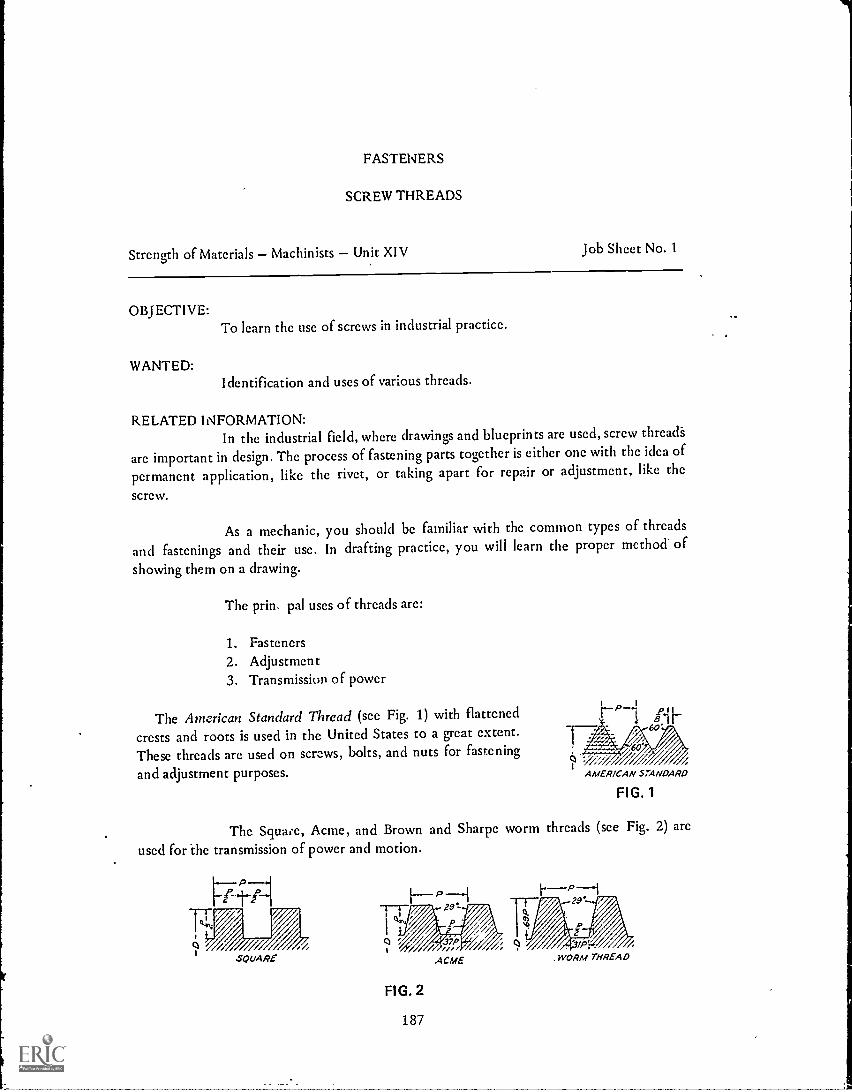
FASTENERS
SCREW THREADS
Strength of Materials Machinists Unit XIV Job Sheet No. 1
OBJECTIVE:
WANTED:
To learn the use of screws in industrial practice.
Identification and uses of various threads.
RELATED INFORMATION:In the industrial field, where drawings and blueprints are used, screw thread's
are important in design. The process of fastening parts together is either one with the idea of
permanent application, like the rivet, or taking apart for repair or adjustment, like the
screw.
As a mechanic, you should be familiar with the common types of threads
and fastenings and their use. In drafting practice, you will learn the proper method of
showing them on a drawing.
The prin. pal uses of threads are:
1. Fasteners2. Adjustment3. Transmission of power
The American Standard Thread (see Fig. 1) with flattened
crests and roots is used in the United States to a great extent.These threads are used on screws, bolts, and nuts for fastening
and adjustment purposes.
P41' .11
? W/7 /AMER/CAN STANDARD
FIG. 1
The Square, Acme, and Brown and Sharpe worm threads (see Fig. 2) are
used for the transmission of power and motion.
141
2.9'r 29'
rP P0 37P
1ME/
FIG. 2
187
,WORM THREAD

The square thread passes on its power parallel to the axis of the thread. Amodified form of the square thread is tl:c Acme, which is stronger and easier to cut. It findsus;: where quick disengaging is necessary, such as the lead screws on lathes.
Transmission of power to a worm wheel by aworm (see Fig. 3) gives the 29° worm thread practicaluse. This thread resembles the acme,as can be seen inFig. 2. The exceptions are in the depth of thread andwidth of the flat at top and bottom. Multiplethreaded worms may have thread angles up to 60degrees.
Someshown in Fig. 4.
of the other
rt"):51.--sore h P-1Ik,L
/ ,,/,,BUTTRESS
,0/
Worm and Wheel
FIG. 3
threads that find use in manufacturing processes
60'
SHARP V
/ i kr
F---- P ----IP2o
o '//. 0 ;%/
iKNUCKLE
/ XX
I P--iIX tI- 55 4
WH/T WORTH
are
FIG. 4The knuckle thread, which is cast or rolled, is used on incandesceat lamps,
plugs, etc. The Whitworth finds great use in England, being applied in the United States insome design work. The buttress thread is used to resist the recoil on guns. Notice the designof the thread whereby it can take pressure in one direction.
On specifying the hand of threads, usually the right-hand is understood tobe called for. If lefthand threads are required (where direction of rotation may cause thescrew or bolt to loosen, as is the case of the wheel on an automobile), they are noted at theend of the thread specification. For example, a right-hand, 1/2" diameter, 13 thread per inch,National Coarse thread would be listed as follows: 1/2-13N.C., while the same thread in a lefthand would be specified: 1/2-13NC. L.H. The hands of a thread can be identified as shownby Fig. 5.
RIGHT-HAND FIG. 5188
LEFT-HAND

When a quick advance of the screw or bolt is required, as on valves, fountainpens, etc., two or more threads are cut side by side. (Have instructor show and explain pitchand lead on single, double, and triple threads).
TOOLS AND MATERIALS:Steel rule, outside calipers, thread gage, right-and left-handed varieties of thefollowing threads:American Standard, square, Acme, buttress, knuckle. Whitworth, and Brownand Sharpe.
PROCEDURE:1. Identify each of the screw threads. Record. 84.2. Taking the strai6ht edge as shown in Fig. 5, identify the hand of the various
threads. Record next to type of thread.
3. Using outside calipers and steel rule, find diameters or size of thread. Recordalongside name of thread.
4. Using thread gage, find number of threads per inch. Record in proper place.
5. Set up column listing threads as they would be specified on drawing.Example: 3/4 10 NC, or V2-6 square
189

SCREW THREADS
SHOP NAME
CLASS JOB SHEET NO. 14-1
QUESTIONS
1. When is a rivet used to fasten parts together?
2. When is a screw used to fasten parts together?
3. Give three uses of threads.a.b.c.
4. Name several types of threads and their uses.
5. What does L.H. after a thread specification indicate?
190

FASTENERS
NUTS, SCREWS AND BOLTS STRENGTH REQUIREMENTS
Strength of Materials Machinists Unit XIV job Sheet No. 2
OBJ ECTI VE:
To learn the Strength requirements of the various screw thread applications.
WANTED:Ways of using screw threads properly.
RELATED INFORMATION:The required screw thread is an important part of the machinist's work.
Using too large a size material may not be bad when you figure the part will not fail orbreak. But from the design angle. too much material is just as bad as too little. Today. witheconomy, the by-word of manufacturing processes. knowledge of proper limits of thestrength of various materials and forms of materials is necessary For proper and good design
On machines where frequent removal and putting back of fastening materialsis necessary, bolts are usually used. Studs are preferred where thread wear is great becausethey can be removed when not of further use. Tap bolts, with larger heads than cap screws.find use under certain conditions.
If two or more bolts are used to hold two parts that have a tendency tocause a shearing action on the bolts, the bolts should be helped by dowel pins. (See Fig. 1)
2 Circv/or Holes in AdityPonge 3'10 NC.2- 2 Halos
iAprop V°
2M1MI* alDaweis ?Regal 1171n7,!_, A
frA,roma ravi
i Ater/nor Key6.406/WIss
Lam--L3
\/ INN
00,291
1.1
31-4
r
ti
1--I-23
r6-- 5
Drill C'bore deep -2 Miles
Lubricant pump
FIG. 1
191
a

Vertical bolts that have a tendency to loosen, due toJAM
vibration or other causes, should be placed with their NUT
heads up.
A combination of nut and jam nut or two jam nuts isused as a locking device (see Fig. 2).
FIG. 2To prevent a nut or haft head from sticking Over the edge of a corner, the
tapped or drilled hole should be located, at least at a radius of half the distance acrosscorners of the bolt head or nut.
BLINDHOLE
Blind holes (see Fig. 3) are usedwhere the danger of gas leakage orrusting out is present. The holesshould not be tapped into the spacehaving gas vapor or liquid pressures.
Proper spacing should be allowedto fit wrenches to nuts or bolt heads.This practice allows proper tighteningand loosening of the fastening devices.
FIG. 3Screws or bolts should be placed or spaced to give the best possible load
action. (sec Fig. 4)
FIG. 4
The sizes and kinds of screws, bolts, and nuts should be kept to a minimumon a design to avoid the use of an unnecessary number of wrenches.
TOOLS AND MATERIALS:
Bracket, lag screw, two plates with bolt holes and dowel pins, jam nuts andbolts, wrenches, split bearing, weights.
192

-1
PROCEDURE:1. Mount bracket on wall with lag screw in lower hole of bracket.
2. Hang weights on end of bracket until you notice the upper edge pulling awayfrom the wall. Record weight.
3. Remove screw and fasten bracket in top hole.
4. Hang weights on end until you have reached about one and one half timesthe weight recorded in step one. What do you notice? Explain the reason forthis happening.
5. Bolt plates lightly together, placing oil or grease on the facing sides. Sec whathappens when the top surface is pushed in one direction while the bottomplate is held in a vise. Be sure dowel pins have been removed.
6. Take plates apart and insert dowel pins. Close plates and fasten together withbolts. See what happens when you try to move the top surface in onedirection while the bottom plate is held in the vise. Record results.
7. Tighten block with one nut. See if you can loosen it with a wrench.
8. Tighten block with two jam nuts. Sec if you can loosen lower nut. Explainyour results.
9. Put shaft in loosened bearing.
10. Tighten until shaft moves freely. if the spacing between the bolt holes wasgreater, what would happen to the bearing cap if it was tightened too much?
193

0,...,4..4,
1
NUTS, SCREWS AND BOLTS
SHOP NAME
CLASS JOB SHEET NO. 14 -2
QUESTIONS
1. Why is using the correct screw thread size important to the machinist?
2. How can bolts be held more securely and thus prevent a shearing action upon them?
3. Why is a jam nut used?
4. What are blind holes?
5. How should screws or bolts be placed?'
6. Why should sizes and kinds of screws, bolts and nuts be kept to a minimum?
7. Why does the upper bolt hold better than just the lower one in the experiment?
194

1
FASTENERS
NUTS, SCREWS AND BOLTS THREADED LENGTH
Strength of Materials Machinists Unit XIV Information Sheet No. 1
0 B J ECT I VE:
To learn the required length of threaded parts and materials used in theirconstruction.
RELATED INFORMATION:The thread length of a bolt or screw should 1),:. able to stand a shearing force
equal to the tension force at the root of the thread. In other words, the threads should notbreak if the threaded part of a bolt or screw is long enough.
The following rules can sl,fely be followed when specifying the length ofbolts or screws and thicknesses of nuts.
CONDITION FORMULA
Steel bolt and nut Nut = Thread Dia.Thickness 3
Steel bolt and cast-iron nut Nut _ Thread Dia.Thickness ')
Wrought-iron and steel nuts Nut = 1 Thread Dia.Thickness 8
Wrought-iron and steel bolts having cast-iron nuts Nut s= 1 T-6-Thd. Dia.
Thickness
Tapped holes in cast iron used for stud bolts, capscrews, tap bolts
Depth = 13/ Thd. Dia.
Tapped holes in steel used for stud bolts, capscrews, tap bolts
Depth = 11/4 TM. Dia.
.
Length of thread on bolts or screws for use incast-iron
Length = 11/2 Thd. Dia.
Length of thread on bolts or screws for use insteel or wrought-iron
...1..........iLength = 1 Thd. Dia.
195

1
The use of boles and screws in the many industries has made themanufacturers conscious of the need for a very good product. With the great advances in thescience of metals,;nore and varied uses of fastening products are being found.
Low-alloy, S.A.E. steels are used for bolts where high impact strength,toughness, and resistance to fatigt'e are required. Hcat-treating (operation of heating andcooling metals) is used to increase these properties.
Where better resistance to heat and corrosion is a requirement, stainless steelfinds use.
The non-ferrous alloys are used to make nuts, bolts, and screws having all orsome of ale following characteristics:
1. Heat resistance
2. Corrosion resistance
3. Acid resistance
4. Egli tness
5. Low coefficient of expansion
196

1
NUTS, SCREWS AND BOLTS
SHOP
CLASS
NAME
QUESTIONS
INFORMATION SHEET NO. 14-1
1. Give the thickness of a nut that could be safely used to withstand a load from thefollowing thread diameters:
a. 1" -8 N.C. steel bolt and nutb. 1"-8 N. C. wrought-iron bolt and cast iron nutc. 1/2"-20 N. F. steel nut
2. Give the depth of tapped hole or length of thread for the following diameters:
a. Yz"-13 N. C. tapped hole in cast ironb. 11/1"-I. 2 N. F. bolt to be used in steel
3. What must the thread length of a bolt withstand?
4. When are low-alloy S.A.E. steels used for bolts?
5. Give some characteristics of non-ferrous alloys used to make nuts, bolts and screws.
197

FASTENERS
SET SCREWS
Strength of Materials Machinists Unit XIV Information Sheet No. 2
OBJECTIVE:To learn the holding power of set screws.
RELATED INFORMATION:A set screw is a round piece of bar stock threaded to the head or completely
threaded. (see Fig. 1) They are used to prevent any movement between two pieces ofmaterial by screwing through one and pressing against the other. (see Fig. 2)
Hex socket wrench
N 9Cupporn1 Ovalpoint Ha/point Holfdogpoint Cone
point HeadlessSquare bead
Cuppoirrt setscrews
AG. 1
134
HEADLESS SEr ,XREW
FIG. 2AMER/CAN-STA JETSCREW
The holding power that a set screw must exert to be of practical use can befound by the following formula;
Holding power (P) 63,000 x Horsepower (HP)Shatt R.P.M.
(63,000 is called a constant. A constant is a figure that has been found to be uniform afterexperimenting regardless of other changes in a formula).
After solving for the holding power, selection of the type ofscrew equal tothe holding power is necessary. The following table gives the ratings of two types of setscrews. (The manufacturing company will send you a rating of their screw).
198

CUP POINT ROUND POINT
THD. DI A.Inch-Pounds)FORCE FORCE(Inch-Pounds)
50 48
s120 10016
3I 240 200
7
16 410 360
1/2 670 600
9
16 1000 910
sT. 1500 1400
3/4 3000 2870
7
T 5000 4850
1 8100 7900
EXAMPLES:What diameter of cup-point set-screw should be used to hold a coupling that isgoing to transmit 3 HP, safely at a shaft speed of 1800 R.P.M. (revolutions perminute)?
Holding power (P) = 63,000 x HP _ 63,000 x 3 = 105 inch-poundsRPM 1800
Looking at the chart, you will find a 4-diameter cuppoint set-screw is required.
199
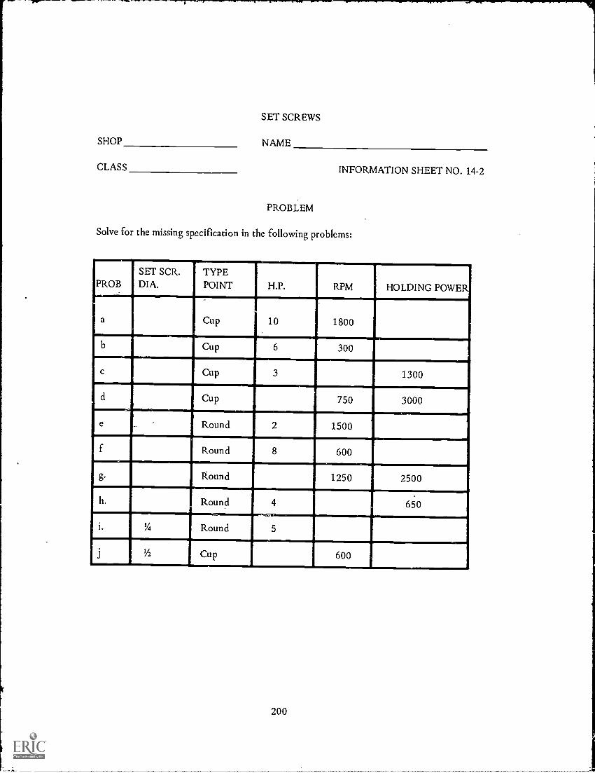
SET SCREWS
SHOP NAME
CLASS
PROBLEM
INFORMATION SHEET NO. 14-2
Solve for the missing specification in the following problems:
PROBSET SCR.DIA.
TYPEPOINT H.P. RPM HOLDING POWER
a Cup 10 1800
b Cup 6 300
c Cup 3 1300
d Cup 750 3000
e . Round,
2.
1500
f Round 8 600
g. Round 1250 2500
h. Round 4 650
i. y4 Round 5
j 1/2 Cup 600
200

FASTENERS
EYE BOLTS
Strength of Materials Machinists Unit XIV Information Sheet No. 3
OBJECTIVE:To learn the safe load to be applied to eye bolts.
RELATED INFORMATION:Eye bolts are used for lifting machines and heavy machine parts. Usually two
bolts are screwed or tapped and so located to balance the suspended load. Material used isforged-mild ductile steel.
When a collar is used on an eye bolt, it should bescrewed so that the surfaces meet.
In Fig. 1, you will see the proper proportions for thedesign of an eye bolt for the safe-working-load formulathat follows:
Safe Load (SL) = 12,000 x Area of Minor Dia.
In other words, if an electric motor weighing 2000 lbs. had to be lifted bytwo eye bolts, you could solve by the formula and see if the eye bolts you specified couldhoist the motor safely.
EXAMPLE:Two eye bolts each have to carry 1000 lbs. If a Yz" dia. eye bolt is specified,you 'could check thusly:
Find minor dia. area Vz" thread in Machinery's Handbook = 0.125
Safe load = 12000 x 0.125 = 1500 lbs.
The bolts will safely carry the motor, since the total load that the bolts cansafely carry is 3000 lbs.
201

SHOP
EYE BOLTS
NAME
CLASS INFORMATION SHEET NO. 14-3
QUESTIONS
1. Why are eye bolts used?
2. If an eye bolt has a collar, what is necessary to give the eye bolt its maximum holdingpower?
3. Make a sketch of an eye bolt for a 1/2" diameter thread. Dimension completely.
4. Can two eye bolts having ;threaded diameters carry a load of 2000 lbs. safely? Show
your work as proof.
5. What is the safe load of four 1/2" threaded diameter eye bolts?
202

FASTENERS
RIVETS
Strength of Materials - Machinists Unit XIV Information Sheet No. 4
OBJECTIVE:To learn the size of rivet to specify for minimum strength.
RELATED INFORMATION:Fastenings are needed where parts of a machine or structure need to be held
fast. If a piece does not require mooring or removal, rivets can be used to make a permanentfastening. They are used to hold together the plates of a tank or boiler, a bridge structure,etc.
A wrought iron or steel rivet is heated, pushedthrough the holes in the connecting parts, and anotherhead is formed. The new head is formed by rivetingmachines (see Fig. 1).
(a) (b)Rivet before and of er driving.
FIG. 1
The diameter of a rivet is proportioned to the plate thickness. The tablebelow lists the required size rivets for lapped joints.
RIVET DIAMETER OF LAPPED JOINTS
Plate Thick-ness_(Inches)
I to 94 3 2
5 to "I 6 3 2
3 to '38 3 2
7 to="1 6 2
7 tO ,..,53 2 8
" to 31 6 4
13 7toI 6 8
Rivet Dia-meter (Inches)
sir
I I
163
77
81 1'
81 1
4
203
RIVETS
SHOP NAME
CLASS INFORMATION SHEET NO. 14-4
PROBLEMS
Specify the proper size rivet for the following plate thicknesses:
a. 1332
b. 916
c.
d.
i4
9
32
f. 78
ig. 7
h.
1.
1132
5
8
1932
204

FASTENERS
KEYSKEYS
Strength of Materials - Machinists - Unit XIV Information Sheet No. 5
OBJECTIVE:To learn how to find the length and size of a key having equal strength tothe shaft.
RELATED INFORMATION:
A key is a steel fastening extending into twomachine parts to prevent movement between them(see Fig. 1).
FIG. 1
The formula for finding the length of a key is as follows:
Square Key Length (KL) = 1.6 x Shaft Dia. (Dia.)
The various sizes of keys are given in the Machinery's Handbook accordingto shaft sizes. Have your instructor show you how to locate the key sizes.
Where large forces are going to be applied to a shaft, such as an automobiletransmission, a spline is used instead of a key. Splines may be four, six, ten, etc.
hub.
FIG. 2
205

k
KEYS
SHOP NAME
CLASS INFORMATION SHEET NO. 14-5
PROBLEMS
1. Solve for key lengths and sizes:a. 1" shaft requires square key
b. 11/4" shaft requires square key
2. What shaft diameter would a 1/4" square key be used on?
3. Why arc keys used on machine parts?
4. What is the shaft diameter for aLix3 222 flat key?
8
5. How deep does a 1/4" key-way go into a shaft?
206

1
FASTENERS
TAPERS
Strength of Materials Machinists Unit XIV Information Sheet No. 6
OBJECTIVE:To learn how tapered shanks firmly seat and center themselves in spindles.
RELATED INFORMATION:A variety of types of tools and machine parts (twist drills, end mills, lathe
centers, etc.) have shanks that taper to fit into spindles or sockets on a machine. Thisarrangement allows for an accurate centzring of the tool in the spindle and offers a fairlyfirm grip for the tool that has to revolve or remain stationary.
There are several standard types of tapers used. The Morse and Brown andSharpe styles are the st...idard ones most commonly used by American manufacturers ofmachines.
Morse tapers are used on a variety of tools and have exclusive use on theshanks of twist drills.
Brown and Sharpe tapers find their greatest use on arbors, collets, andmilling machine tool spindles.
Other tapers that find usage on machines are the Jarno and the AmericanStandard.
A taper pin, on the other hand, is used as a means of fastening a part to ashaft when the load is not too great. They make the mating parts turn as one.
FIG. 1
-...--F-- ..-.....T.
,
TAPERS
SHOP NAME
CLASS INFORMATION SHEET NO. 14-6
QUESTIONS
1. What is a taper?
2. Why is a taper used?
3. Name several types of tapers.
4. Which two are mostly used?a.b.
5. Give an exclusive machine area for each type.
6. Why are taper pins used?
Ask your instructor for Achievement Test No. 14 after completing this unit's work.
208
1

SHAPING AND FORMING METALS
HOT WORKING
Strength of Materials Machinists - Unit XV nforniation Sheet No. 1
OBJECTIVE:To learn how Metals arc shaped by hot-working.
RELATED INFORMATION:Casting, as you have learned, is a basic way of forming metals. The special
kind of casting made by pouring molten steel into a cast-iron mold is called an ingot. Thisingot is the shape of the metal before shaping and forming.
A metal in a powder state can be formed by pressing it in a metal form. Theresulting heat from the pressure causes the material-to fuse into a solid. Small parts, gears,etc. make good use of this method.
Hot- working of metals is thought of as an operation that mechanicallydeforms the metal in a temperature range that will not affect the normal grain structure.Sume of the common methods used in the hot shaping of metals are rolling, forging,hammering, and extrusion.*JRoller
Meitti afterMetal
forsins
t ;INRoller-
ROLLING
E XTRUSION
Mad
209
i*NDieMetal before
forg ing
DIE. FORGING
4-141e+01 beforeI IL
N-J
1
% 14-- Metal after////>)//// ///77
HAMMERING

Rolling and forging get the steel into the required shape and improve itsmechanical properties. Where simple shapes are to be made in large quantities, rolling is thecheaper process of the two. Sheets, structural shapes, rails, etc. are rnadc by passing theheated material between two rolls revolving in opposite directions. The rolls have a spacebetween them somewhat less than the height of the piece entering them. The rolls grip themetal and deliver it in a reduced and slightly formed shape to the next set of rollers. Thisprocess is continued until the required shape is formed.
Forging or hammering is the simplest method of reducing , actal to thedesired shape by deforming it. The steam hammer is the principal type of hammer used forhot forging, although the advance in hydraulic presses may have an effect on this method.The forging done by the hammer method is of the blacksmith variety. When drop-forging isused, a piece of metal about the size of the required shape is placed between die faces anddrawn together. The die resembles the finished part. Automotive parts of steel and brass,naval gun barrels, oil-distilling apparatus, tool steel and wrought-iron parts are usually madethrough forging.
Some metals can be formed by pressing through an opening. Brass, lead andits alloys are formed by this method,called extrusion. The advantages of this method arcperfectly round rods or rods ()Evaded shapes. The metal to be extruded is placed in a closedchamber fitted with an opening at one end and a piston at the other end. The metal isforced out of the opening by hydrauli. pr-ssure, forming the desired shape through the useof a die.
210
WM/
CLASS
SHOP
10. Explain the operation of rolling.
9. Which is the cheaper process, rolling or forging?
7. What is hot working?
8. What do rolling and forging do to steel?
2. Why is there an exception?
3. What is the simplest method of shaping metal?
4. Explain what is meant by drop forging.
6. Give the name of the casting before it is shaped and formed.
1. What is the basic form for the greatest percentage of metals?
5. What is extrusion and why is it used?
HOT WORKING
NAME
QUESTIONS
211
INFORMATION SHEET NO. 15-1

SHAPING AND FORMING METALS
COLD WORKING
Strength of Materials - Machinists Unit XV Information Sheet No. 2
OB JECTI VE:
To learn how metals are cold-worked.
RELATED INFORMATION:The discovery of metals was the birth of working metals at ordinary
temperatures. Cold-working of metals was an art practiced by the ancients. Today, modernpractices have given us cold-rolling, pressed metals, and drawing, to name a few.
WIRE DRAWING
Metal before
Die
Metal
DEEP DRAWING
Metal before
212
CUPPING
Punch
Metal
Die
STAMPING

Cold-rolling produces a finish for hot-rolled metals. The bright, smoothsurface of cold-rolled steel, for example, insures accurate dimensioning and increased tensilestrength. Cold-rolling is used to produce sheets, strip steel, and bar stock, following aprocess similar to hot-rolling. The difference may be that the cold-rolled metal may have tobe annealed after several passes through the rollers to keep it in a workable condition.
Metal in the form of cold-rolled or hot-rolled sheets or strips may be formedinto various shapes in metal dies. Through the use of proper die design, pressing of the metalmay consist of many operations, some of which are bending, shearing, blanking, punching,flanging, embossing, etc. Flat stock of steel, brass, copper, aluminum, or other metal isplaced between the dies of a slow - action press which forces the metal to assume the desiredshape. The modern automobile and airplane, household appliances, workshop tools, aresome of the products produced in this fashion.
Drawing is the operation of reducing the thickness of a material whileincreasing its length or size. Many shapes of tubes, bars, wire, and sheets are produced bythis process. Kitchen utensils, such as pots and pans, would cost too much if drawing wasnot used.
In any of the cold-working processes, it must be remembered that the metalscan only be deformed to a certain point, otherwise cracking is likely to result. You mustrealize that a metal, like an elastic band, has a certain point to which it can be stretchedwithout breaking, otherwise you will not be able to specify the correct metal for a part.
213

COLD WORKING
SHOP NAME
CLASS INFORMATION SHEET NO. 15-2
QUESTIONS
1. When was cold-working discovered?
2. Give the cold-working process for the following parts:a. Household appliancesb. Strip steelc. Wired. Bar stock
3. Name a few modern practices used in coldworking.
4. What precaution must be taken in the cold-rolling of metals? Explain.
Ask your instructor for Achievement Test No. 15 after completing this unit's work.
214
WELDING
DEFINITIONS
Strength of Materials Machinists Unit XVI Information Sheet No. 1
OBJECTIVE:To learn the various types of welds and how they are defined.
RELATED INFORMATION:Welding is one of the most important ways of putting together metal parts.
This method is used when casting costs are too high or where design calls for lighter weightthan can be achieved by casting. Through the welding process, the complicated automobilestructure is attained, as well as the many forms of machinery, buildings, and aircraft andshipbuilding industries.
Welding of metals may be done in three ways depending upon the heatingmaterials and metals bein,,-; used. The methods are pressure, fusion, and casting.
Pressure welding consists of heating the parts to be joined to a plastic or nearinciting stag. The parts are pressed together at a contact pressure that squeezes out anyimpurities and results in good union of the parts. Today most pressure welds are made byheating the parts by electricity. The current heats most rapidly at the contact between theparts,where the resistance is the highest. Pressure is applied to the plastic surfaces and theyarc squeezed together to remove oxide and slag to form a firm bond. This method is appliedto both butt and lap welding in the production of pipe out of sheet by rolling the sheet intoa cylinder and welding the long scam. Fabrication of automobile bodies, metal furniture,refrigerators are some of the many other uses of pressure welding.
Fusion welding is a joining process in which the union of the parts isobtained by actual fusion of metal along the contacting surfaces of the mating parts. Theheat necessary for fusion welding may be supplied by oxyacetylene flame, by an electric arcbetween metallic or carbon rods and by any process following the above forms. This type ofwelding finds a variety of uses in the various machine and structural industries.
Thermit welding can be considered the casting-process method,where molteniron is run into a mold built around the parts at the point at which they are to beconnected. The liquid metal used consists of finely divided iron oxide and aluminum,whichis lighted in a crucible. The reaction gives the welded members a liquid metal that forms afirm union of the parts on cooling.
215
SHOP
DEFINITIONS
NAME
CLASS INFORMATION SHEET NO. 16-1
QUESTIONS
1. Name the three types of welds.a.b.c.
2. When is welding used?
3. Explain the three types of welds and give a use for each.
4. Which method do you think is being used by industry? Why?
5. Do you think welding will replace the casting process? Why?
216

WELDING
OXYACETYLENE
Strength of Materials Machinists Unit XVI Job Sheet No. 1
OBJECTIVE:
To learn how to weld with the oxyacetylene torch and the various joints thatcan be used.
WANTED:
Explanation of how metals are welded by oxyacetylene.
RELATED INFORMATION:
Many different metals can be welded with the oxyacetylene torch.
The intense heat required for welding metal by gas process is obtained bylighting a mixture of oxygen and acetylene, or oxygen and hydrogen.
TOOLS AND MATERIALS:
Welding equipment, welding rods, and the following metals:Cast iron, steel, and angle iron.
PROCEDURE: (To be done in machine shop by instructor)1. Explain use of welding equipment:
a. Torch d. Torch tip sizeb. Gas and Gages e. Welding rodsc. Hood 1. Welding safety
2. Using pieces of steel, prepare and weld them in the following ways:a. Lap joint d. Beadb. Butt joint c. "V" groovec. Fillet weld
PI LLET WELD
LAP JOINT
BUTT JOINT WITH V GROOVE
CORNER JOINT WITH FILLETAND BEAD WELDS
217

3. Show necessary steps in welding cast iron and limitations.
4. Demonstrate various methods of welding angle iron.
5. Students should record notes and ask any questions to make welding of metals clearin their minds.
218
OXYACETYLENE
SHOP NAME
CLASS JOB SHEET NO. 16-1
QUESTIONS
1. What is oxyacetylene?
2. Name some of the safety precautions to follow when using this type of equipment.
3. Make sketches showing the following welds:a. Lap joint
b. Butt joint
c. Fillet weld
4. State the gas mixture used in the oxyacetylene process.
5. That is the advantage of gas welding in field work?
219

WELDING
ARC
Strength of Materials Machinists Unit XVI Job Sheet No. 2
OBJ ECTIVE:
WANTED:
To learn what is meant by arc welding and how it is used.
Explanation of how arc welding is used.
RELATED INFORMATION:An electric arc is a continuous spark between two terminals. The tremendous
heat at the point of welding melts a small pool of metal in the work. Additional metal isobtained from the electrode or filler rod.
All steels are weldable under proper conditions. To obtain high weldingspeeds, it is necessary to go deeply into the plates being welded.
TOOLS AND MATERIALS:. Arc welding equipment, pieces of steel.
PROCEDURE: (To be done in the machine shop)1. Explain use of arc welding equipment.
2. Make the following welded joints:a. Cornerb. Edge
EDGE JOINT
c. Teed. Double butt
TEE JOINT WITH FILLET WE LDS
DOUBLE BUTT
220

ARC
SHOP NAME
CLASS JOB SHEET NO. 16-2
QUESTIONS
1. What is arc welding?
2. Name some of the safety precautions in using this type of equipment.
3. Make sketches of the following welds:a. Corner
b. Double butt
c. Tee Joint
4. What type of voltage is needed to operate arc welding equipment?
5. Does the arc welding set-up require a greater or lesser amount of money to install andoperate than gas welding?
Ask your instructor for Achievement Test No. 16 after completing this unit's work.
221

MECHANICAL TESTING OF METALS
TESTING LABORATORY
Strength of Materials Machinists Unit XVII Information Sheet No. 1
OBJECTIVE:
To learn how metals are mechanically tested.
RELATED INFORMATION:The purpose of testing laboratories is to determine the strength and
properties of materials. The results insure quality and economy in manufacture andperformance its use on machines or structures for the materials tested.
Testing machines may vary, but they are designed to determine themechanical properties of materials. Some tests commonly used are tension, compression,torsion, flexure, hardness, endurance to repeated stresses,and impact tests. Special tests mayinclude resistance to weather, light exposure, paper folding, vibration, etc.
ASSIGNMENT:
Your instructor will plan a field trip to a testing laboratory in order toacquaint you with the mechanical testing of materials.
222
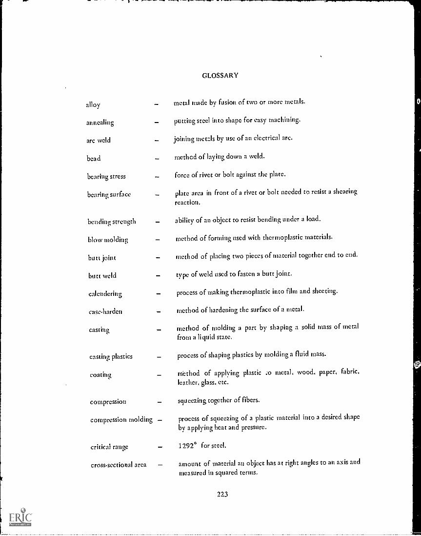
alloy
annealing
arc weld
bead
bearing stress
bearing surface
bending strength
blow molding
butt joint
butt weld
calendering
caseharden
casting
casting plastics
coating
compression
GLOSSARY
metal made by fusion of two or more metals.
putting steel into shape for easy machining.
joining metals by use of an electrical arc.
method of laying down a weld.
_ force of rivet or bolt against the plate.
plate area in front of a rivet or bolt needed to resist a shearing
reaction.
ability of an object to resist bending under a load.
method of forming used with thermoplastic materials.
method of placing two pieces of material together end to end.
type of weld used to fasten a butt joint.
process of making thermoplastic into film and sheeting.
method of hardening the surface of a metal.
method of molding a part by shapingfrom a liquid state.
a solid mass of metal
process of shaping plastics by molding a fluid mass.
m'ethod of applying plasticleather, glass, etc.
squeezing together of fibers.
compression molding
critical range
cross-sectional area
,o metal, wood. paper, fabric.
process of squeezing of a plastic material into a desired shape
by applying heat and pressure.
1 29/ ° for steel.
amount of material an object has at right angles to an axis and
measured in squared terms.
223
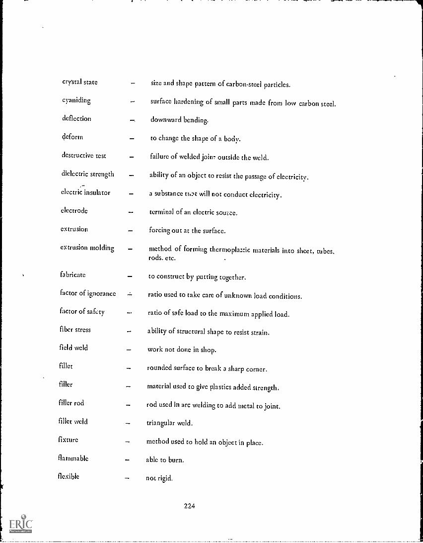
crystal state size and shape pattern of carbon-steel particles.
cyaniding surface hardening of small parts made from low carbon steel.
deflection downward bending.
deform to change the shape of a body.
destructive test failure of welded joim outside the weld.
dielectric strength ability of an object to resist the passage of electricity.
electric -insulator a substance tti:t will not conduct electricity.
electrode terminal of an electric sour ce.
extrusion forcing out at the surface.
extrusion molding method of forming thermopla ;:ic materials into sheet, tubes,rods. etc.
fabricate to construct by putting together.
factor of ignorance ratio used to take care of unknown load conditions.
factor of safety ratio of safe load to the maximum applied load.
fiber stress ability of structural shape to resist strain.
field weld work not done in shop.
fillet rounded surface to break a sharp corner.
filler material used to give plastics added strength.
filler rod rod used in arc welding to add metal to joint.
fillet weld triangular weld.
fixture method used to hold an object in place.
flammable able to burn.
flexible not rigid.
224

flexure ability to bend.
forging forming a shape by heating and hammering.
forming shaping.
fracture of metals breaking a piece of metal to show the texture.
fulcrum about which a lever turns.
fusion welding process of joining metal parts in _he molten state withoutapplying mechanical pressure.
gas cutting dividing a material by means of a chemical behavior ofoxygen.
grain structure crystal-like formation of metals.
hardness amount of resistance of a metal to penetration.
heat - treatment method of treating metals.
high - pressure method of shaping thermosetting plastics by use of high heatlaminating and pressure.
hood covering used to- protect face from welding heat, light andmetal splattering.
hot-working metal shaped when hot.
hydraulic method of offering resistance when a quantity of a liquid isforced through a small opening.
ingot a mold in which hot metal is cast.
injection molding method of forcing fluid plastic at high pressure through anozzle into a cold mold.
intricate difficult to understand; complicated.
lap joint
lever
lineal measure
two objects laid out in such a manner that one extends overthe other.
a rigid piece capable of turning around a point known as afulcrum.
distance along a line.
225

load a weight resting upon something.
mill scale ?articles left on metals after shaping in steel mills.
modulus of elasticity ratio of unit stress to unit strain.
nitriding surface hardening of special alloy steels.
non-ferrous any metal lacking iron or steel.
normal grain required crystal patterns of metal.structure
normalizing improving grain structure of otherwise poor steel.
oxyacetylene mixture of oxygen and acetylene.
pearlite structures cooling a steel so that the structure contains 0.85% carbon.
physical properties nature characteristics which identify materials.
plastic nature capable of being deformed continuously without rupture.
plumb vertical or true.
point of zero shear section where the bending moment is the greatest.
precipitation hardening
pressure weld
process of hardening by heat treatment.
process of welding metals in a fluid state by aid of mechanicalpressure.
projection weld localizing the heat in joining overlapped parts.
reaction body force opposed to a Weight or load.
rein forcing plastics molding impregnated reinforced material under low pressure.
resistance butt weld pressure welding of butt joint.
resistance welding pressure welding process wherein the welding heat is obtainedby passing an electric current between the contact areas.
resultant equal in effect to two or more forces.
226

root zone at bottom of cross-sectional space provided to contain a
fusion weld.
seam weld linear resistance welding process.
shear action tending to divide a body.
shock strength ability of a body to resist a blow.
shrinkage the amount a material decreases.
specification statement containing details of construction.
sprig small headless nail or brad.
spot weld fastening of materials at various points to hold it in place.
stiffener used to keep an object from bending.
stress subject to action of an external force.
tempering making hardened steel suitable for a cutting tool.
tension act of stretching.
thermoplastic softens when exposed to heat, hardens on cooling.
thermosetting plastic permanent setting plastics.
translucent admitting diffused light causing objects beyond to be hard todistinguish.
transparent admitting light so that objects can be seen beyond it.
uniformly distributed weight evenly placed over the entire beam.
load
web vertical section of structural member.
227

FORMULAS
Unit Stress = Resistance (R) Total force (F)Cross-sectional Area (A)
Unit Strain = Deformation (D) = Total Strain (S)Length of Body (L)
Shear (s) = Force (F)Cross-sectional Area (A)
Ultimate Strength (St) = Force (F)Cross-sectional Area (A)
Factor of Safety (X) =
Holding Power (P) =
Ultimate Strength (St)Allowable Working Stress (W)
63,000hxatHt Horsepower (HP.
Eve Bolt Safe Load (SL) = 12,000 x Area of Minor Dia. of Thread
Square Key Length (KL) = 1.6 x Shaft Dia. (Dia.)
228

ABBREVIATIONS
R1 =
R2 =
F1 =
F2 =
F3 =
it =
first resultant
second resultant
first force
second force
third force
pi (3.1416)
in.2 = square inches
lb. (s)
foot
inches
pounds per square inch
A = area
# =
ft. =
=
psi =
229
1-

REFERENCE BOOKS
Machinery's Handbook 15th Ed. The Industrial Press, N. Y.
Wegner and Arthur The Machinist's and Draftsmen's Handbook D. Van Nostrand Co..Inc., N. Y.
Pisani Essentials of Strength of MaterialsD. Van Nostrand Co., Inc., N. Y.
Engineering Materials Manual Reinhold Publishing Co., N. Y.
Metals Technology Delmar Publishing Co., N. Y.
Leighon Chemistry of Engineering MaterialsMcGraw -Hill Book Co., N.Y.
Mcrsercau Materials of Industry McGraw-Hill Book Co., N. Y.
Johnson Metallurgy American Technical Society, Chicago
Woldman Materials Engineering of Metal Products Reinhold Publishing Co., N. Y.
230

INDUSTRIAL MATERIALS
Strength of Materials Machinists Unit I Achievement Test No. 1
OBJECTIVE:To see if you can recognize the various industrial materials.
TOOLS AND MATERIALS:Pieces of cast iron, steel, aluminum. lead, copper, brass.
ASSIGNMENT:Identify by name the various pieces of metal.
a. c.
b.
QUESTIONS:
1. Name the two groups of abrasives
a.
b.
d. f.
2. Tell how the two types of plastic are classified and explain the difference between them.
3. What is the chemical symbol for iron?
4. Give some uses of steel.
5. Name five non-ferrous metals.
STUDENT'S NAME

THE PRODUCTION OF IRON AND STEEL
Strength of Materials Machinists Unit II Achievement Test No. 2
OBJECTIVE:
To see if you understand how iron and steel are produced.
QUESTIONS:
1. Match the process and resulting product.
a. Blast furnace u. high-grade tool steel
b. Aston-Byers v. high carbon steel
c. Bessemer w. lowcarbon steel
d. Open-hearth x. wrought iron
e. Crucible y. fine quality steel
1. Electric z. pig iron
2. Name several uses for wrought iron.a.b.c.
3. State three physical characteristics of Bessemer steel.a.b.C.
4. Name several uses for open-hearth steel.a.b.c.
5. Give the composition of the crucible furnace charge.a.b.c.
6. Give two uses for electric process steel.a
b.
STUDENT'S NAME

PRODUCTION OF NON-FERROUS METALS
Strength of Materials Machinists Unit III Achievement Test No. 3
OBJ ECTI V E:
To see if you have learned how non-ferrous metals are produced.
QUESTIONS:1. Match the metal with the process used in the prodp,-7ion of the metal.
a. Bayer (1) Copperb. Smelting and refining (2) Zincc. Electrolysis of natural salts (3) Cadmiumd. Electrothermal distillation (4) Nickele. Orford (5) Magnesium1 Thermit (6) Aluminum0. Electrolytic methods (7) Antimony
(8) Chromium(9) Tin
Match the metal with its use:a. Aluminumb. Copperc. Leadd. Zince. Tin1. Cadmium
g. Magnesiumh Nickeli. Mercuryj. Tungstenk. SilverI. Chromiumm. Molybdenum
(1) Tank linings(2) Galvanizing material(3) Flashlight work(4) Chemical vats(5) In high-tensile steel(6) Coins(7) Filaments(8) Cast or wrought shapes(9) Part of low-melting, alloy(10) In spring steel(11) Plating of hardware(12) Plating on containers(13) In laboratory apparatus(14) Electrical wiring(15) Hand tools
STUDENT'S NAME

GENERAL PHYSICAL PROPERTIES
Strength of Materials Machinists Unit IV Achievement Test No. 4
OBJECTIVE:
To see if you know the general physical properties of industrial materials.
QUESTIONS:1. Why are metals of greater use than any of the other industrial materials?
a.
b.
c.
d.
e.
f.
g.
2. Name two Light- weight metals that can be used in various ways.a.b.
3. How can steel be made soft or hard?
4. Find densities of the following in a handbook:a. Cast Ironb. Leadc. Brassd. Aluminume. M;Id steel
5. Name five general physical properties of industrial materials.
a.
b.
c.
d.
e.
STUDENT'S NAME

MECHANICAL PROPERTIES OF MATERIALS
Strength of Materials Machinists Unit V Achievement Test No. 5
OBJECTIVE:
To see if you know the meaning of the various mechanical properties ofmaterials.
PROBLEMS: A. Match column (A) with column (B) for each of the following:(A) (B)
1. Ductility a. Ease with which a material can be hammered into anydesired shape.
2. Elastic limit
3. Stiffness
4. Hardness
5. Malleability
,,i
b. The ability to resist rupture when greatly extendedin tension.
c. Property of a material whereby it can support a largeload without losing its shape.
d. Ability of a material to sore energy and resist impact.
c. When a material has been so deformed that it will notreturn to its original shape.
6. Impact strength E. The toughness of a body to take the work-energy of ablow or falling weight.
7. Resilience g. Resistance of a substance to the separation of itsparticles by a penetrating action.
B. Using the formula for Modulus of Elasticity
E = F x L, solve the following:A x s
1. A 1-square inch steel bar, 60 inches long has a weight of 10,000 lbs. suspended atthe lower end which causes the bar to stretch 0.02 inches. What is the modulus ofelasticity?
2. A 29-ft. long structural steel bar having a cross-sectional area of 3 square inches andelasticity of 29,000,000 lbs. per square inch has a weight of 10,000 lbs. attached toit. How many inches does it stretch?
C. Give a chemical test for the following metals:1. Magnesium2. Moncl3. Stainless steel4. Tin5. Steel

THE PLAIN CARBON STEELS
Strength of Materials Machinists Unit VI Achievement Test No. 6
OBJECTIVE:To see if you have learned the construction and uses of plain carbon steels.
QUESTIONS:1. What do all steels contain?
2. The effect of the carbon in the steel depends upon:-a.
b.
c.
3. How are steels classified? Why?
4. Give the approximate composition of the following steels:
a. C1010
b. 1041
c. C1006
5. Match the following:a. 1006 1. connecting rodsb. 1015 2. cold chisels
d. 10353. filesc. 1025
4. screwsc. 1045f. 1065
5. springs6. screw drivers
h. 1095g. 1085 7. levers
8. razors9. crankshafts
10. chain
STUDENT'S NAME
THE CONTROL OF PHYSICAL PROPERTIES OF METALS
Strength of Materials Machinists Unit VII Achievement Test No. 7
OBJECTIVE:To see if you have learned how to control the physical properties of metals.
QUESTIONS:1. Explain what is meant by the heat treatment of steel.
2. The effect of the carbon in the steel depends on:a.
1.
b.
c.
Name several reasons for warping an4racking.
4. Why is a hard case given to steel?
5. What is the main purpose of annealing?
6. Explain the term normalizing.
7. Why is nitriding used?
8. What is cyaniding?
9. How can properties of non-ferrous metals be altered to meet exactingrequirements of various applications?
10. Match the coated metal with its use.
COATED METALa. Tin plateb. Zinc galvanizingc. Parkerizingd. Bonderizingc Surface oxidation
USEu. gun partsv. sheet metal workw, building up of work partsx. canning industryy. surface hardening of steelz. resisting wear on pistons

THE ALLOY STEELS
Strength of Materials Machinists UnitVIII Achievement Test No. 8
OBJECTIVE:To see if you know the reasons why steel alloys are being used in production of objects.
QUESTIONS:1. What is an alloy steel?
2. Give two examples of elements that combine with steel to form an alloy.a.b.
3. Give the approximate combination for the following steels:a. 5150b. 3115c. 1340d. E3310c. C1010
4. State a Ilse for each of the following steel alloys:a. 2340b. 9260c. 4140d. 6150c. 4340
5. Can you identify the color code for the following:a. SAE 1010b. SAE 3115c. SAE 4140d. SAE 5195c. SAE 6125
6. What are two possible effects of alloying?a.
b.
7. How is corrosion-yesistance taken care of by alloying steel?
8. What does red hardness mean?
9. Which element alloyed with steel shows the greatest effect in the making of aharder product?
10. Why is a protective coating put on iron?
-STUDENVS:NAME

THE PRODUCTION OF CASTINGS
Strength of Materials Machinists Unit IX Achievement Test No. 9
OBJECTIVE:To see if you know how castings are produced.
QUESTIONS:1. What is meant by casting?
2. Give examples of parts that may be cast.
3. Name the various types of castings.
4. In what kind of furnace is the metal for the following cast parts melted?
a. Cast-steel machine housingb. Bronze worm-wheel blankc. Cast-iron engine block
5. What is a pattern? What is the most commonly used'material to make it?
6. How are patterns preserved?
7. Why are metal molds used?
8. Give the advantages and disadvantages of die casting.
9. Why are centrifugal castings made?
10. Name some possible defects of castings.
STUDENT'S NAME

NON-FERROUS ALLOYS
Strength of Materials - Machinists Unit X Achievement Test No. 10
OBJECTIVE:To see if you can recognize and know the uses of the various non-ferrousalloys.
PROBLEMS:Match column (A) with column (B).
1. Commercial Bronze a. Valve stems
2. Low Brass b. Flexible hose
3. Duralumin c. Dye vats
4. Dow Metal d. Low thermal expansion
5. Monel Metal e. Screen wire
6. Alnico f. Easy-melting alloy
7. Solder g. Bearing metal
8. Babbitt Metal h. Permanent magnets
9. Invar i. Screws
10. Muntz Metal j. Hammered forgings
STUDENT'S NAME

THE STRUCTURE OF METALS
Strength of Materials Machinists, Unit XI Achievement Test No. 11
OBJECTIVE:To see if you have learned the structure of metals.
QUESTIONS:
1. Name the two characteristics upon which the structure of metal depends.a.b.
2. What happens when a force exceeding the elastic limit is applied to a metal?
3. If you continued to deform a piece of metal, you would cause it to become:
4. Make a sketch of a body-centered cubic pattern.
5. Sketch the three steps in the growth of a crystal.
STUDENT'S NAME

SIMPLE STRESSES
Strength of Materials Machinists Unit XII Achievement Test No. 12
OBJECTIVE:To see if you know simple stresses.
QUESTIONS:1. Find the unit stress for the following: (R = )
a. A 2-square-inch cross-sectional rod having a load of 100,000 lbs. applied toone end.
b. A 2 inch x 2 inch steel bar supporting a load of 120,000 lbs.
c. A 1" diameter steel cable raising a load of 40,000 lbs.
2. Find the unit strain for the following: (D = )
A 30-inch-long wire that stretches 0.00.30 inches when a load is applied.
3. State two machine parts in the shop that depend upon correct bearing loads fortheir operation.
a.
b.
4. How can twisting be overcome?
5. What is elastic limit?
6. Explain what is meant by ultimate strength.
7. State the difference between tension and compression.
8. Why is a safety factor used?
9. If a rod has a cross-sectional area of 3 square inches supporting a load of 120,000lbs., what is the tension in the rod?
10. A machine weighs 2000 lbs. The weight is equally distributed on four legs having across-sectional area of 2 square inches. What is the compressive force in each leg?
,STUDENVS-NAME.

BEARINGS
Strength of Materials Machinists Unit XIII Achievement Test No. 13
OBJECTIVE:To see if you understand the use of bearings on industrial machines.
QUESTIONS:1. What is friction?
2. Give three principles of friction.
a.
b.
C.
3. State two types of friction.a.b.
4. What is meant by the coefficient of friction?
5. Why are lubricants use d on moving parts?
6. Can lubrication always take care of friction? Why?
7. Name three types of bearings.a.b.c.
8. Give an example of a machine in your shop for each type of bearing.
--STUDENT2S-N A M F.

FASTENERS
Strength of Materials Machinists Unit XIV Achievement Test No. 14
OBJECTIVE:To see if you can specify workable fasteners for certain loads.
PROBLEMS:1. Identify the following threads:
2. Give three uses of threadsa.b.
3. What does L.H. mean on a thread specification?
4. Why is a jam nut used?
5. What are blind holes?
6. When are low-alloy SAE steels used for bolts?
7. Why are set screws used?
8. Explain the use of eye bolts.
9. When are rivets used in place of screws?
10. When are keys and splines used on a machine?
STUDENT'S NAME__ _

SHAPING AND FORMING METALS
Strength of Materials Machinists Unit XV Achievement Test No. 15
OBJECTIVE:
PROBLEMS:
To see if you can identify the proper methods of shaping or forming metals.
Match the methods in column B with the formed object in column A.
A B
1. Ingot a. Cold-rolling
2. Rails b. Hot rolling
3. Naval gun barrels c. Casting
4. Round rods d. Pressed metals
5. Strip steel c. Drawing
6. Workshop tools f. Forging
7. Kitchen utensils g. Extrusion
8. Structural shapes
9. Bar stock
10. Wire
STUDENT'S NAME

WELDING
Strength of Materials Machinists Unit XVI Achie.vment Test No. 16
OBJECTIVE:To see if you have learned the various types of welding.
QUESTIONS:1. State the three types of weld and give a use for each.
a.b.c.
2. When is welding used?
3. Explain when the oxyacetylene equipment is used.
4. Make sketches of the following welds:a. Lap Joint
b. Butt Joint
c. Fillet Weld
d. Bead
e. "V" Groove
f. Corner Joint
g. Edge Joint
h. Tee
5. Explain when the arc welding equipment is used.
6. Name some safety precautions when using welding equipment.
7. What must be done to cast iron before it can be welded? Why?
8. How can high welding speeds be obtained?
9. What type of voltage is needed to operate the arc welding equipment?
10. Which method, gas or arc, is more economical to install?