document 1331 revision a october 15, 2019
TRANSCRIPT

DOCUMENT 1331
REVISION C
June 7, 2021
Instruction Manual
Pro APF Series LED
Inset Runway Guard Light
FAA Type L-852G
OR
Stop Bar Light
FAA Type L-852S 8-inch aluminum optical housing with
ductile iron support ring
Cooper Lighting Solutions
Airport Lighting Products
1200 Kennedy Road
Windsor, CT 06095
Copyright © 2021 Cooper Lighting Solutions
For Parts or Technical Service Call (860) 683-4300
DOCUMENT 1331
REV. C
Instruction Manual
PRO APF Series LED
Inset Runway Guard Light L-852G
1
1 Table of Contents
1 Table of Contents .................................................................................................................... 1
2 Revisions ................................................................................................................................ 2
3 Product Warranty .................................................................................................................... 3
4 Warning Labels ....................................................................................................................... 4
5 Safety Notices ......................................................................................................................... 5
5.1 Keep Away From Live Circuits ....................................................................................... 5
5.2 Resuscitation .................................................................................................................... 5
6 Recommended Test Equipment and Tools ............................................................................. 6
7 Part Number Explanation ....................................................................................................... 8
8 General Description ................................................................................................................ 8
9 Installation .............................................................................................................................. 9
9.1 Installation Bolt Torque ................................................................................................. 10
9.2 Heico-Lock Installation Guidlines ................................................................................. 11
10 Maintenance .......................................................................................................................... 11
10.1 Cleanliness and Workmanship ....................................................................................... 12
10.2 Maintenance Program .................................................................................................... 12
10.3 Cleaning the Lenses ....................................................................................................... 13
10.4 Replacing the LED Modeule .......................................................................................... 13
10.5 O-Ring Replacement ...................................................................................................... 14
10.6 Lens Replacement .......................................................................................................... 15
10.7 Power Lead/Feedthru Replacement ............................................................................... 16
10.8 Power Supply Bluetooth Board Replacement ................................................................ 16
10.9 Power Supply Troubleshooting and Replacement ......................................................... 17
10.9.1 Visual Inspection ................................................................................................ 17
10.9.2 Electrical Inspection ........................................................................................... 19
10.9.3 Power Supply Replacement ................................................................................ 20
10.9.4 Resetting a IRGL Power Supply’s E-Prom ........................................................ 21
10.10 Pressure Test ................................................................................................................ 22
11 Spare/Replacement Parts List ............................................................................................... 23
12 Tables and Figures ................................................................................................................ 25
13 Appendix A: Bluetooth Instruction ...................................................................................... 32

DOCUMENT 1331
REV. C
Instruction Manual
PRO APF Series LED
Inset Runway Guard Light L-852G
2
2 Revisions
Revision Issue/Reissue
Letter Number Description Checked Approved
B A220-151 Initial Issue with ECN 10/12/20 PG
C A221-076
Pg.7: Updated P/N Explanation for addition
of -4 option of logitrac monitoring
(852GAP1);
Pg.23: Added item 20, 21616-6; Item 12
10035-0073 was 10035-0062;
Pg.25: Fig 4A was Fig 4; Added Fig 4B;
Pg.30: Added Figure 10 , 11, 12 & 13;
Pg.29: Updated table 3 for logitrac
monitoring option;
Corrected Jumper figure callouts throughout
manual.
6/7/21 PG

DOCUMENT 1331
REV. C
Instruction Manual
PRO APF Series LED
Inset Runway Guard Light L-852G
3
3 Product Warranty
Warranty Refer to Cooper Crouse-Hinds Airport Lighting Products Terms and Conditions for product specific
warranty information.
(f) EXCEPT FOR THE EXPRESS WARRANTY SET FORTH ABOVE, SELLER
PROVIDES PRODUCTS AS-IS AND MAKES NO OTHER REPRESENTATIONS OR
WARRANTIES, EXPRESS OR IMPLIED, STATUTORY OR OTHERWISE,
REGARDING THE PRODUCTS, THEIR FITNESS FOR ANY PARTICULAR
PURPOSE, THEIR MERCHANTIBILITY, THEIR QUALITY, THEIR
NONINFRINGEMENT, OR OTHERWISE. IN NO EVENT SHALL SELLER BE
LIABLE FOR THE COST OF PROCUREMENT OR INSTALLATION OF
SUBSTITUTE GOODS.

DOCUMENT 1331
REV. C
Instruction Manual
PRO APF Series LED
Inset Runway Guard Light L-852G
4
4 Warning Labels
DANGER:
DANGER The hazard or unsafe practice will result in severe injury or death.
WARNING:
WARNING The hazard or unsafe practice could result in severe injury or death.
CAUTION:
CAUTION The hazard or unsafe practice could result in minor injury.
NOTICE:
NOTICE Possibly dangerous situation, goods might be damaged.
IMPORTANT:
IMPORTANT Helpful information.

DOCUMENT 1331
REV. C
Instruction Manual
PRO APF Series LED
Inset Runway Guard Light L-852G
5
5 Safety Notices
This equipment is normally used or connected to circuits that may employ voltages that are
dangerous and may be fatal if accidentally contacted by operating or maintenance personnel.
Extreme caution should be exercised when working with this equipment. While practical safety
precautions have been incorporated in this equipment, the following rules must be strictly
observed:
5.1 Keep Away from Live Circuits
Operating and maintenance personnel must at all times observe all safety regulations. Do not
perform maintenance on internal components or re-lamp with power ON.
5.2 Resuscitation
Maintenance personnel should familiarize themselves with the technique for resuscitation found
in widely published manuals of first aid instructions.
IMPORTANT:
IMPORTANT See FAA Advisory Circular AC 150/5340-26 for additional information.
6 Recommended Test Equipment and Tools
There is a wide variety of tools and equipment needed to safely and correctly perform airfield
lighting equipment installation and maintenance. In addition to the obvious tools (screwdrivers,
wrenches, etc.), there is a specialized equipment needed to do the job.
Multimeter
One of the most important pieces of test equipment is the Multimeter. It is used to measure
voltages, currents, and resistances. Almost every maintenance task requires the use of a
multimeter at one point or another. A quality meter in good repair and calibration is a must
because airfield lighting power distribution equipment produces non-sinusoidal waveforms,
traditional average reading meters are inaccurate and have very limited use. Checking or
adjusting equipment based upon incorrect current reading may dramatically reduce lamp life and
adversely affect power equipment performance. A meter with TRUE RMS measuring capability
with a current clamp-on accessory is needed to accurately measure distorted or chopped

DOCUMENT 1331
REV. C
Instruction Manual
PRO APF Series LED
Inset Runway Guard Light L-852G
6
waveforms. All meter manufacturers offer TRUE RMS measuring meters. The following is a
short list of TRUE RMS Multimeters from Fluke:
Manufacturer Model Number
Fluke 287
Our recommended multimeter is the Fluke 287 with the Fluke I800 current clamp accessory.
Refer to the equipment manufacturer’s manuals for the proper use, maintenance and calibration
(if necessary) of all meters.
Anti-seize (marine grade preferred, Henkel/Loctite P/N 34395 or 34026 or equal
(http://www.henkelna.com/adhesives/product-search-1554.htm?nodeid=8797882515457) with a
K factor of 0.18 for fully coating the frangible coupling threads. This will help facilitate removal
of sheared frangible couplings or fixtures for replacement/maintenance. Only use an anti-seize,
as other materials may wash away.
WARNING:
IMPORTANT
Failure to apply anti-seize at installation will result in near
impossible to impossible removal of a frangible coupling from a
threaded hub over time.
A calibrated torque wrench (micrometer adjustable solid audible/tactile “click” impulse when
torque value attained with an accuracy of +/- 4%) to fit a 9/16 or 14 mm socket for drive size of
the socket to tighten the fixture base plate 3/8-16 UNC hex bolts to 336 in-lbs -0, +0% [37.9 -0,
+10%] with an anti-seize that has a K factor of 0.18 applied to fully cover the bolt threads.
Torque wrenches: Sturtevant Richmont P/N 810748, range 100 to 600 in-lbs or equal, or
Sturtevant Richmont P/N 810782, range 10 to 50 Nm or equal. Certificate of calibration
included with suggested torque wrenches. Note, never loosen bolts with a torque wrench.
A calibrated adjustable torque screwdriver to torque the external ground screw to 6 in-lbs
[1.81Nm] minimum. Sturtevant Richmont P/N 810568 (comes with bits [hex, slotted, Torx,
Phillips, sq. recess, bit holder, socket adapter], case and certificate of calibration), range 2 to 36
in-lbs/0.2 to 4 Nm or equal. Note, never loosen screws with a torque screwdriver.
Needle nose pliers for installing the extremely small header jumper onto a spare Power Supply
J203 header when required or removing the flag type fast-on terminals from the power supply.
Xcelite P/N NN54-2 miniature pliers, fine needle nose, ESD-Safe or equal.

DOCUMENT 1331
REV. C
Instruction Manual
PRO APF Series LED
Inset Runway Guard Light L-852G
7
A grounded ESD Wrist Strap when working on or handling fixture power supplies or LED/Heat
sink assemblies. ESD Wrist Straps, also known as anti-static Wrist Straps, are used to prevent
electrostatic discharge (ESD) by safely grounding a person working with electronic equipment or
at an electronic assembly facility. It consists of a band of fabric with fine conductive fibers
woven into it. The fibers are usually made of carbon-filled rubber, and the strap is bound with a
stainless-steel clasp or plate. They a usually used in conjunction with an ESD table mat on the
workbench, or a special static-dissipating plastic laminate on the workbench. ESD Products
brand (http://www.esdproduct.com/esd_wrist_straps.php) or equal.
A #2 x 4 inch (101.6 mm) long Phillips head screw driver for installing the Isolation
Transformer’s FAA L-823 Style 8 secondary receptacle retainer plate screws into one of the
recommended base plates for a L-867 base.
Most tools indicated above can be purchased from MSC Industrial Supply Co.
(http://www.mscdirect.com/), or McMaster-Carr (http://www.mcmaster.com/).

DOCUMENT 1331
REV. C
Instruction Manual
PRO APF Series LED
Inset Runway Guard Light L-852G
8
7 Part Number Explanation – Inset Runway Guard Light, L852G
8 General Description
The Cooper Lighting Solutions Inset Runway Guard Light (IRGL) is a Style 3, ITS verified FAA
L-852G and Inset Stop Bar light is a Style 3, FAA L-852S per FAA AC 150/5345-46 and EB67
(latest versions). It is designed for installation at the intersection of runways and taxiways or any
other location where visual guidance of moving aircraft or ground vehicles is desirable. The
fixture is designed to fit on a FAA L-868, steel, Size B, light base per FAA AC 150/5345-
42(latest version) and have a total height above grade/ground level of .250 inch. The fixture is
uni-directional, and flashes on/off in unison within a hold bar. It is weatherproof and will endure
roll over loads without damage. The light fixture consists of a ductile iron support ring and a
removable aluminum optical assembly. The ductile iron ring is mounted to a light base with six
bolts (3/8-16 UNC x 7/8 lg., 410 black oxide stn. stl.) and lock washers (3/8, stn. stl.). The
aluminum housing is secured to the ductile iron ring using two high-strength bolts and two high-
DOCUMENT 1331
REV. C
Instruction Manual
PRO APF Series LED
Inset Runway Guard Light L-852G
9
strength shear pins. The aluminum housing has a die cast bottom housing that is attached using 4
screws. A polyurethane O-ring is used to provide a watertight seal between the inner cover and
the optical housing. Electrical connections are made at one feed-thru assembly in the inner cover.
The feed-thru have ITS verified L-823 plugs for connecting to FAA L-830/ L-831 Isolation
Transformers. Lenses are held into the aluminum housing with a bracket, gasket, molded
elastomeric boot and two screws. The yellow light beam color is produced using white LED’s and
optics with a dichroic coating on the lenses All hardware is type 18-8 stainless steel. The
complete light unit is 11.94 inches in diameter, 5.00 inches deep and weighs 25 lbs. All units
leave the factory pressure tested. if the unit is serviced during its lifetime, it must be re-tested to
ensure it remains waterproof.
IMPORTANT
IMPORTANT:
Do not open any fixture unless the warranty period has expired.
Opening a fixture will void the warranty
CAUTION
CAUTION:
Never handle the light assembly by the leads as this can break the
waterproof seal
9 Installation
The Style 3 IRGL units are shipped complete, including the LED module(s), and are ready for
installation as received. Installation of a light unit is to be done with primary POWER OFF
and SECURED. At each light location, install a steel, Size B, 12 inch deep minimum, L-868
Light Base per FAA AC 150/5340-4 (latest revision). Place the properly sized isolation
transformer(s) in the light base and make necessary primary power connections using L-823
connectors. Isolation transformer requirements are dependent on a light unit’s heater option and
whether it is used with a Logitrac device. All isolations transformers are 6.6 ampere secondary
models. Verify that the mounting flange on the light base is clean and the O-ring (optional on
deep cans) is coated with Dow Corning FS 1292 grease and is in place on the light base. Connect
the plug(s) from the light unit to the secondary of the previously installed isolation transformer(s).
Installation tool, Crouse-Hinds P/N 19999, will ease in the installation and removal of the light
unit (See Figure 4A). The threaded eyebolts on the lifting tool screw into threaded holes in the
light fixture. Lower the light unit straight down onto the base. The light fixture is subject to
optical misalignment or mechanical damage if not seated properly. Verify the light beam is
properly orientated for the individual location. Secure the light unit to the base per section 9.1.
All 852G-AP1 light units are flashing lights. For light units with the “YO” designator in the part
number, the light will flash ON first in the cycle. For light units with the “YF” designator in the
part number, the light will flash OFF first in the cycle. This allows the light installers to arrange

DOCUMENT 1331
REV. C
Instruction Manual
PRO APF Series LED
Inset Runway Guard Light L-852G
10
either an alternating flashing bar of lights (i.e. YO---YF---YO---YF---YO---YF---… etc.), in
which the YOs flash on while the YFs flash off in an alternating fashion, or a solid bar of lights
that flash in unison (i.e. YO---YO---YO---YO---YO---YO---… etc.). In the case of an accidental
undesirable light bar installation (i.e. YO---YF---YF---YO---YO---YO---…etc.), each 852G-AP1
light unit’s immediate powered flashing state is reprogrammable using Bluetooth technology. See
APPENDIX A for Bluetooth access instructions.
9.1 Installation Bolt Torque
• Use fully threaded, 3/8-16 bolts meeting requirements of FAA EB83A. (P/N 21716 is
recommended.)
• Use Heico-Lock or Nord-Lock stainless steel lock-washers per FAA specifications*.
• Mounting base holes must be degreased, cleaned, and dried prior to bolt installation.
• Base-to-fixture mating surfaces must be degreased, cleaned, and dried prior to
installation.
• Apply marine grade anti-seize (K=.18) per manufacturer’s instructions to each bolt.
• Install the 3/8-16 bolts with lock-washers per lock-washer manufacturer’s guidelines.
• See Section 9.2 for Heico-Lock installation guidelines (2014)
• Achieve a full final torque of 28 FT-LBS (37.9 N-m) ±10% with a calibrated torque
wrench.
• Impact wrenches are not recommended as installation tools.
• Check torque and re-torque all bolts within 2 weeks of initial installation.
• Maintain all bolts by checking and re-torqueing per FAA specifications*.
• If any lubricants or thread locking compounds are used (not recommended), torque must
be recalculated based on K factor provided by lubricant or compound manufacturer.
• New bolts and lock-washers shall be used each time a light unit is removed from its base.
*Refer to the following specifications for FAA installation and maintenance recommendations:
• AC150/5340-26 “Maintenance of Airport Visual Aids”
• AC150/5345-46 “Specification for Runway and Taxiway Light Fixtures”
• FAA Engineering Brief No. 83A “In-pavement Light Fixture Bolts”
WARNING:

DOCUMENT 1331
REV. C
Instruction Manual
PRO APF Series LED
Inset Runway Guard Light L-852G
11
WARNING
8” Pro APF IRGL optical assemblies are designed to withstand a maximum torque
of 28 ft-lb (336 in-lb) per bolt, assuming K=.18 lubricant and appropriate
superior-grade 3/8” hardware, however other components within the light fixture
installation (i.e. base-can, extension rings, spacer rings, etc.) may not be capable of
supporting such a load. Eaton Crouse-Hinds recommends following the installation
bolt torque values and methodology outlined in Section 9.1.
9.2 Heico-lock Installation Guidelines (2014)
Step 1: Hand tighten to ensure that 2-3 threads extend beyond the nut on through-bolt applications.
Step 2: Tighten each bolt to one-third of the final required torque following the pattern as shown
below.
Step 3: Increase the torque to two-thirds following the pattern shown below.
Step 4: Increase the torque to full torque following the pattern shown below.
Step 5: Perform one final pass on each bolt working clockwise from bolt 1, at the full final torque.
10 Maintenance
The preferred method of maintaining these lights is to periodically and systematically replace the units
and return them to the maintenance shop for renovation. As an alternative, the units can be serviced in the
field. However, it is recommended that field servicing be limited to checking bolt torque per section 9.1
and cleaning the lens only as described in Section 10.3.
DOCUMENT 1331
REV. C
Instruction Manual
PRO APF Series LED
Inset Runway Guard Light L-852G
12
WARNING
WARNING: The warranty is void if the screws holding the L852G optical housing to the
inner cover are loosened or removed.
10.1 Cleanliness and Workmanship
Service life depends upon the entire assembly being waterproof. All surfaces must be clean, dry and free
of all foreign matter if the light unit is to operate for extended periods without requiring maintenance.
10.2 Maintenance Program
In order to insure maximum light unit life, the installed units should be subject to a maintenance program
in accordance with the following: A daily operation check should be made of the lighting unit. The lights
should be energized and visually inspected. If any units are not lit and/or partially lit, the location of the
unit, along with the pocket that is out, should be recorded for future troubleshooting. A replacement light
unit should be installed per instruction in Section 9 with the primary POWER OFF and SECURED. The
affected light unit can be troubleshot in a clean, safe working area or returned to Crouse-Hinds Airport
Lighting for repair.
WARNING
WARNING: The warranty is void if the screws holding the L852G optical housing to the
inner cover are loosened or removed.
10.2.1 Regular cleaning is necessary to insure inset lighting units operate at maximum efficiency. The
lens should be cleaned periodically per Section 10.3. The weather and the location of the units
will dictate the regularity and type of cleaning.
10.2.2 Inset light hold-down bolts should be checked for proper torque per section 9.1 and whenever a
unit is serviced regardless of the season. Light units in and around the touchdown zone area are
specially prone to vibration damage if the mounting bolts are not properly torqued. The mounting
surface of the light base must be clean and free of foreign matter when checking mounting bolts.
NOTICE
NOTICE: The warranty is void if other than Crouse-Hinds Airport Lighting Products
parts are used to re-lamp or rebuild the light unit.
DOCUMENT 1331
REV. C
Instruction Manual
PRO APF Series LED
Inset Runway Guard Light L-852G
13
10.2.3 Snowplow operators should exercise extra care not to strike the light units with snowplow blades.
Use rubber blades for added protection to the unit. After snow removal operations, inspect all
light units to locate and replace, if necessary, any damaged light assemblies. Passes over the light
rows should be made with a power broom only if practical. Whenever snowplows must traverse
in-pavement light units, they should be traveling at less than 5 mph or have the blades lifted clear
of the unit. Recommended snow removal techniques are described in AC 150/5200-23.
10.2.4 The light is designed to exclude both ground and surface water from entering. If the lights are not
properly maintained (i.e., bolts tightened and seals in good condition) water may enter the unit.
To prevent this from occurring, it is recommended that each unit be inspected for the presence of
water at least once a month. More frequent inspection is desirable during and following rainy
seasons.
10.2.5 If any light unit contains water, the water should be removed and the entire unit cleaned and
dried. If any of the electronics have been damaged, it may not be cost effective to make a field
repair, but rather send it back to Crouse-Hinds Airport Lighting for rebuild. Perform a pressure
test per Section 10.10 to locate the source of the leak. Refer to the o-ring, lens, and power lead
sections, 10.5, 10.6, & 10.7 as needed to make repairs. After any repair, pressure test again per
Section 10.10.
10.3 Cleaning Lenses
With a compressed air blast or suitable brushes, remove all accumulated debris from the light channel.
Clean the outer lens surface with a detergent solution. If the lens is coated with a substance impervious to
the detergent, a suitable solvent should be sparingly applied with a wad of cotton or a patch of cloth on
the end of a wood splint. After the solvent has acted, the remaining solvent and softened coating should
be removed with a clean piece of cotton or cloth. Care should be taken to avoid excessive contact
between the solvent and the lens seal. Remove all remaining solvent from lens and lens seal. A gentle air
blast may be used. It is good practice to inspect for damage to the optical housing and/or water intrusion
into the unit anytime a lens is cleaned. Water droplets would be visible on the inside of the lens if
moisture had entered the unit. If it is determined that moisture has entered the unit, refer to Section 10.2.5
for possible causes and maintenance procedures.
NOTICE
NOTICE: The LED PCB is warm when light unit is energized and remains warm for a
short time after unit is turned off.

DOCUMENT 1331
REV. C
Instruction Manual
PRO APF Series LED
Inset Runway Guard Light L-852G
14
10.4 Replacing the LED Module
WARNING
WARNING: The Warranty is void if the screws holding the L852G optical housing to the
inner cover are loosened or removed.
Refer to Table 1 to determine the appropriate LED Module for your light unit. Remove and secure
power to the fixture. Separate the Optical Assembly from the outer ring by removing the two bolts.
There are two pry slots in the optical housing to help separate the optical assembly from the
support ring. Disconnect the fixture lead from the isolation transformer. Turn the optical assembly
upside down and remove the four screws holding the inner cover to the light housing. Disconnect the
power supply lead from the LED assemblies. Remove the two cap screws holding the light reflector and
LED board to the block heat-sink. Leave the heat-sink fastened to the optical housing. Clean the inside
surfaces of the lens with denatured alcohol. Using a thin layer of thermal grease between the bottom of
the board and the block heat-sink, place the new LED board on the block heat-sink. Align the small hole
and slot of the LED board with that of the heat-sink. Be sure to keep the new light reflector clean and
free of contaminants. Insert the new light reflector’s alignment pins into the small hole and slot of both
the LED board and heat-sink beneath the board. Tighten the screws to 6-8 in-lbs. Connect the power
supply leads to the new LED assemblies. Inspect the feed-thru terminals for signs of corrosion. Replace
feed-thru assemblies per Section 10.7 if corrosion is found. Inspect/replace the optical housing’s O-ring
gasket per Section 10.5. Assemble the inner cover onto the light housing. Tighten the mounting screws to
30 in-lbs. Perform a pressure test as described in Section 9.10. Connect the light unit lead from the
isolation transformer. Clean the mounting flange area of the light base. Secure the light to the base per
Section 9.1.
10.5 O-Ring Replacement
Refer to Table 1 to determine the appropriate O-Ring for your light unit. Every time the unit is opened,
the O-ring must be closely examined and replaced, if necessary. Any O-ring that is stretched, torn, has
permanent set, or some other defect which would prevent it from forming a watertight seal, and must be
replaced with a new O-ring.
WARNING
WARNING: The warranty is void if the screws holding the L852G optical housing to the
inner cover are loosened or removed.
NOTICE
NOTICE: A bad O-ring seal is the most common cause of inset light unit leaks. A new
O-ring must be installed every time the optical assembly is opened

DOCUMENT 1331
REV. C
Instruction Manual
PRO APF Series LED
Inset Runway Guard Light L-852G
15
First, remove and secure power to the light unit. Separate the Optical Assembly from the
outer ring by removing the two bolts. There are two pry slots in the optical housing to help
separate the optical assembly from the support ring. Disconnect the light unit lead from the
isolation transformer. Open the light unit and disconnect the LED wires as described in
Section 10.4. Remove the old gasket from the groove in the inner cover using a plastic (or
comparably soft) tool. Carefully clean the inner cover’s gasket groove and the mating sealing
surface on the optical housing. Take care not to damage the sealing surfaces or the new gasket.
Coat the gasket with a thin layer of Dow Corning FS 1292 lubricating grease. Position the new
gasket in the center of the groove and press it into place. Torque the inner cover screws to 30 in-
lbs. Perform a pressure test as described in Section 10.10. Connect the light unit lead from the
isolation transformer. Clean the mounting flange area of the light base. Install the light unit into
the light base per Section 9.1.
10.6 Lens Replacement
WARNING
WARNING: The warranty is void if the screws holding the L852G optical housing to the
inner cover are loosened or removed.
If a lens is broken, leaks, or is badly pitted or scarred, it must be replaced. It is highly recommended that
this task be performed in a clean shop environment. Refer to Table 1 to determine the appropriate lens
replacement for your light unit. REMOVE and SECURE power to the light unit. Separate the Optical
Assembly from the outer ring by removing the two bolts. There are two pry slots in the optical housing
to help separate the optical assembly from the support ring. Disconnect the fixture lead from the
isolation transformer. Turn the optical assembly upside down and remove the four screws holding the
inner cover to the light housing. Disconnect the power supply lead from the LED module. Remove the
two screws holding the light reflector and LED board to the block heat-sink. Carefully remove the LED
board with reflector attached and place aside in a clean location. Leave the heat-sink attached to the
optical housing. Remove the two lens retaining bracket screws from the optical housing. Remove the
lens-retaining bracket and discard the lens-retaining gasket. Firmly push the lens/boot assembly from the
outside of the optical housing; discard the old lens and boot. Thoroughly clean the lens opening with
denatured alcohol and allow it to dry. Inspect the lens opening for scratches or pits; a damaged lens
opening surface will not seal properly. Place the new lens boot over the replacement lens. Apply a thin
coat of Dow Corning FS 1292 grease over the entire outside surface of the lens boot. Align the lens/boot
assembly in the lens opening (from the inside of the fixture) and press it into place. Verify that the lens
boot is not pinched in the lens opening. Using the new lens retaining gasket, fasten the lens retaining
bracket to the optical housing. Torque the mounting screws to 25-30 in-lbs. Re-install the LED module
per Section 10.4. Connect the power supply lead to the LED module. Inspect the feed-thru terminal for
signs of corrosion. Replace feed-thru assembly per Section 10.7 if corrosion is found. Inspect/replace the
optical housing’s O-ring gasket per Section 10.5. Assemble the inner cover onto the light housing.
Tighten the mounting screws to 30 in-lbs. Perform a pressure test as described in Section 10.10. Connect

DOCUMENT 1331
REV. C
Instruction Manual
PRO APF Series LED
Inset Runway Guard Light L-852G
16
the light unit lead from the isolation transformer. Clean the mounting flange area of the light base. Secure
the light to the base per Section 9.1.
10.7 Power Lead/Feed-thru Replacement
WARNING
WARNING: The warranty is void if the screws holding the L852G optical housing to the
inner cover are loosened or removed.
Refer to Table 1 to determine the appropriate Feed-thru replacement for your light unit. REMOVE and
SECURE power to the light unit. Separate the Optical Assembly from the outer ring by removing the
two bolts. There are two pry slots in the optical housing to help separate the optical assembly from
the support ring. Disconnect the light unit lead from the isolation transformer. Disconnect the power
supply leads from the feed-thru terminals. Remove the feed-thru by unscrewing the retaining collar. Clean
the mounting surfaces with denatured alcohol and allow them to dry. Apply a thin coat of Dow Corning
FS 1292 grease to the mounting flange of a new feed-thru. Apply a drop of Loctite 243 to the feed-thru
adapter threads. Screw the feed-thru retaining collar onto the adapter. Torque the retaining collar to 25-30
in-lbs. Reconnect the power supply leads to the feed-thru terminals. Inspect/replace the inner cover’s
gasket per Section 10.3. Inspect/replace the optical housing’s O-ring gasket per Section 10.5. Assemble
the inner cover onto the light housing. Tighten the mounting screws to 30 in-lbs. Perform a pressure test
as described in Section 10.10. Connect the light unit lead from the isolation transformer. Clean the
mounting flange area of the light base. Secure the light to the base per Section 9.1.
10.8 Power Supply Bluetooth Board Replacement
Refer to Table 1 to determine the appropriate Bluetooth Board replacement for your light unit. REMOVE
and SECURE power to the light unit. Separate the Optical Assembly from the outer ring by removing
the two bolts. There are two pry slots in the optical housing to help separate the optical assembly
from the support ring. Disconnect the light unit lead from the isolation transformer. Disconnect the LED
cable from the expansion board, located on top of the main power supply in the inner cover assembly. Remove
the single nut, lock washer, and washer above the expansion board, which secures the expansion board to the
power supply underneath it. Note: There are 2 spacer washers between the expansion board and the power
supply bracket. Remove the expansion board form the power supply by gently pulling the expansion board up
and away from the power supply. Discard the old expansion board as an electronics assembly. Replace the 2
spacer washers, align and engage the connectors of the new expansion board with the power supply and press
it into place. Replace the flat washer, lock washer and nut on to the mounting screw. Torque the nut to 16-18

DOCUMENT 1331
REV. C
Instruction Manual
PRO APF Series LED
Inset Runway Guard Light L-852G
17
in-lbs. Connect the ends of the LED cables to the new expansion board. Inspect the feed-thru terminal for
signs of corrosion. Replace feed-thru assembly per Section 10.7 if corrosion is found. Inspect/replace the
optical housing’s O-ring gasket per Section 10.5. Assemble the inner cover onto the light housing.
Tighten the mounting screws to 30 in-lbs. Perform a pressure test as described in Section 10.10. Connect
the light unit lead from the isolation transformer. Clean the mounting flange area of the light base. Secure
the light to the base per Section 9.1.
10.9 Power Supply Troubleshooting and Replacement
10.9.1 Visual Inspection
If a light unit is under warranty, please contact Crouse-Hinds Airport Lighting for assistance. DO
NOT open the unit. If the unit is opened, the warranty is VOID. If the warranty period has
expired and troubleshooting is required, follow the steps below to find the root cause.
Replacement parts will be required for testing of the different components of the light unit.
Follow the steps in Section 10.4 to open the fixture. Verify all the wires are not pinched or
damaged and that the wire insulation is intact. Verify the input AC is connected to the feed-thru
(see Figure 1 below). Verify the power supply connections and appropriate jumper setting per
Figures 7, 8 and 9.
AC INPUT CONTACTS
HEATER CONTACTS (WIRE JUMPER MUST BE INSTALLED ON FIXTURES WITHOUT HEATERS)
JUMPERS
HEATER SENSOR
LED DRIVER
Figure 1: Power Supply Assemblies With Option 1
OPTION 1 BLUETOOTH BOARD

DOCUMENT 1331
REV. C
Instruction Manual
PRO APF Series LED
Inset Runway Guard Light L-852G
18
Figure 2: Power Supply Connections
*See Figures 7, 8 and 9 Jumpers shown in Figure 1 are for example only.
IMPORTANT:
IMPORTANT
The jumpers must be placed in the correct position(s) for proper
operation of the appropriate fixture.
Replace any damaged or burned cables. Replace a damaged LED module per Section 10.4. Replace a
damaged power supply per Section 10.9.3.

DOCUMENT 1331
REV. C
Instruction Manual
PRO APF Series LED
Inset Runway Guard Light L-852G
19
10.9.2 Electrical Inspection
WARNING:
WARNING
Contact Crouse-Hinds Airport Lighting for assistance prior to operating
a failed fixture. There may be dangerous voltage present on the input AC
pins of the power supply.
It is recommended that a ferro style constant current regulator (2.8 to
6.6ARMS) with a 10/15W isolation transformer or a voltage limited
constant DC current source be used to test failed fixtures to limit the
input voltage.
A buzzing or humming noise coming from the isolation transformer may
indicate a failed power supply or LED module. It is also an indicator of
dangerous voltage on the primary and secondary sides of the
transformer.
NOTICE:
NOTICE
Applying a constant voltage greater than 50V (AC or DC) to the input
will cause damage to the power supply.
Applying input current to the power supply without the heater or jumper
installed will cause damage to the power supply.
Follow the steps in Section 10.9.3 to open the fixture and remove the power supply as required.
The power supply continuously monitors the status of the LED module. There is a green status
LED (see Figure 2) that may be visible through the potting. A blinking LED indicates the power
supply has detected a fault condition.

DOCUMENT 1331
REV. C
Instruction Manual
PRO APF Series LED
Inset Runway Guard Light L-852G
20
Fault conditions include:
• Disconnected or ‘Open’ LED module
o Replace cable if damaged or ‘open’.
• Incorrect jumper setting or missing jumpers
o See Figures 7, 8 and 9 for proper jumper setting.
• More than 25% of the driven LED ‘Shorted’
o Replace LED module per Section 10.4.
Figure 3: Power Supply Status LED Location
If the status LED is not visible or not lit, replace the power supply per Section 10.9.3 or contact Crouse-
Hinds Airport Lighting Products for assistance.
10.9.3 Power Supply Replacement
CAUTION:
CAUTION
Power supply is hot when light unit is energized and remains hot for a short
time after light unit is turned off.
Refer to Table 1 to determine the appropriate Power Supply replacement for your light unit.
REMOVE and SECURE power to the light unit. Separate the optical assembly from the support
ring by removing the two bolts. There are two pry slots in the optical housing to help separate the
optical assembly from the support ring. Disconnect the light unit lead from the isolation transformer.

DOCUMENT 1331
REV. C
Instruction Manual
PRO APF Series LED
Inset Runway Guard Light L-852G
21
Turn the optical assembly upside down and remove the four screws holding the inner cover to the
light housing. Disconnect the power supply leads from the feed-through terminals and LED module.
On P2 units, disconnect the contact closure cables from the power supply. For units with an arctic kit
(heater), disconnect the heaters’ power and temperature sensor cables form the power supply.
Remove the three power supply bracket screws. Remove the power supply bracket with attached
power supply. Discard the old power supply and bracket as an electronics assembly. New power
supply will come as a sub assembly of the power supply, power supply bracket, and Bluetooth board
assembled from the factory. Configure the jumper settings for the new power supply per Figures 7, 8
and 9.
IMPORTANT:
IMPORTANT
The jumpers must be placed in the correct position(s) for proper operation
of the appropriate fixture.
Apply thermal grease to the mating surface of the new power supply and secure the power supply
bracket using 3 #10, 2-piece lock washers, torque the three bracket mounting screws to 25-30in-lb.
Connect the ends of the LED cables to the expansion board. Inspect the feed-thru terminal for signs of
corrosion. Replace feed-thru assembly per Section 10.7 if corrosion is found. Inspect/replace the
optical housing’s O-ring gasket per Section 10.5. Assemble the inner cover onto the light housing.
Tighten the mounting screws to 30 in-lbs. Perform a pressure test as described in Section 10.10.
Connect the light unit lead from the isolation transformer. Clean the mounting flange area of the light
base. Secure the light to the base per Section 9.1.
10.9.4 Resetting a IRGL power supply’s E-Prom
This process is required to reset to power supply’s e-prom for detecting the number of LEDs that
could be out, based on the LED’s forward voltage it will be used with. This is best accomplished
in your maintenance facility following safe electrical practices during the reprogramming of the
power supplies, as dangerous currents will be present on exposed connections when the power
supply is energized.
DANGER:
DANGER
Lock out electrical power to the IRGL power supply prior to
reprogramming jumper set-up, and after reprogramming during removal
of programming jumper.

DOCUMENT 1331
REV. C
Instruction Manual
PRO APF Series LED
Inset Runway Guard Light L-852G
22
With power off, add a jumper, 10047-1677 to power supply J200 between positions 1 and 2.
Attach the LED type to be used with the power supply, installing the correct jumpers to J203 if
required per Figures 7, 8 and 9. Install the LED board to the power supply per Section 10.4. With
all personal safely isolated from your maintenance facility reprogramming set-up, energize the
circuit. The circuit must run for a minimum of 10 seconds, and with the power supply at the high
step of 6.6A during this 10 second minimum for the e-prom to reset and accept its new settings.
The power supply will blink the LED after 10 seconds, indicating it has been reset. Remove the
jumper from power supply J200, positions 1 to 2 after the power supply is safely de-energized
after the 10 second minimum reset period.
10.10 Pressure Test
A light unit should be subjected to a 20-psi maximum air pressure test to verify that it is waterproof
whenever it has been opened or components have been replaced. A tire valve style pressure fitting is
located on the underside of the inner cover. Pressurize the light unit to 20-psi using a regulated/controlled
air source, then place it in a tub of water or use a soap solution to locate escaping air bubbles. Carefully
inspect the areas around the lens, inner cover seal, and feed-thru adapter for leaks. Relieve the internal air
pressure before installing the light unit or attempting to repair a leak.
WARNING
WARNING: Do not exceed 20-psi when pressure testing the light unit. Serious injury
and/or permanent damage to the light unit may result if a higher air pressure
is used. Once the pressure test is complete, be sure to relieve the air
pressure.

DOCUMENT 1331
REV. C
Instruction Manual
PRO APF Series LED
Inset Runway Guard Light L-852G
23
11 Spare/Replacement Parts List
Item Part Number Description
LED Module Replacements 1 21797 Yellow LED PCB
2 21794 Red LED PCB
Prism/Lens Replacements
3 21676-TY Prism (Yellow Color)
4 21619-4 Prism with Heater (Yellow Color)
5* 21642-1 Prism Replacement Kit (Red Color)
6* 21644-1 Arctic Kit Replacement Kit (Red Color)
Power Supply Replacements
7 21696-H-1205 Power Supply (Yellow)
8 21696-HT-1205 Power Supply, Arctic Kit (Yellow)
9 21696-1 Power Supply (Red)
10 21696-2 Power Supply Arctic Kit (Red)
Power Cord Assembly
11 K3326992 Lead Assembly
Seal, Bottom Cover 12 10035-0073 O-Ring
2-Piece Lock Washer Kit
13 21647-2 2-Piece Washer Replacement Kit, QTY 2
14 21647-XX 2-Piece Washer Replacement Kit, Customer Specified QTY Installation Bolts
15 21716-XX Screw, Hex Head, 3/8-16 UNC, 410 Black Oxide Stainless Steel meeting FAA EB 83A, Customer Specified Length (see Table 2 below).
Cable Replacements
16 21615-2 Cable Assembly with Ferrite
17 50612-2 BLUETOOTH BOARD (OPTION 1 ONLY)
18 21180 Option 2 Gasket
19 21764 Support Ring With Pins
20 21616-6 Cable assembly for LOGITRAC Monitoring
*Kit includes prism/lens, lens boot, lens gasket, lens bracket, bracket screws.
Table 1: Spare/Replacement parts

DOCUMENT 1331
REV. C
Instruction Manual
PRO APF Series LED
Inset Runway Guard Light L-852G
24
Table 2: 21716-XX bolt lengths
P/N Length
(IN) P/N
Length (IN)
21716-07 0.88 21716-22 2.75
21716-08 1.00 21716-24 3.00
21716-09 1.13 21716-26 3.25
21716-10 1.25 21716-28 3.50
21716-11 1.38 21716-32 4.00
21716-12 1.50 21716-36 4.50
21716-14 1.75 21716-48 6.00
21716-16 2.00
21716-18 2.25
21716-20 2.50

DOCUMENT 1331
REV. C
Instruction Manual
PRO APF Series LED
Inset Runway Guard Light L-852G
25
12 Tables and Figures
Figure 4A: Part Layout P1 Option

DOCUMENT 1331
REV. C
Instruction Manual
PRO APF Series LED
Inset Runway Guard Light L-852G
26
Figure 4B: Installation View of Inner Cover P2 option

DOCUMENT 1331
REV. C
Instruction Manual
PRO APF Series LED
Inset Runway Guard Light L-852G
27
Figure 5: 19999 Installation (Lifting) Tool
TCL Fixture Shown

DOCUMENT 1331
REV. C
Instruction Manual
PRO APF Series LED
Inset Runway Guard Light L-852G
28
Figure 6: WIRING DIAGRAM
FIGURE 7: PART NUMBER 852SAP1-RN-NF-XX-X STOP BAR
POWER SUPPLY J203 JUMPER CONFIGURATION
FIGURE 8: FIRST ON (YO) POWER SUPPLY J203 JUMPER POSITION
PART NUMBER 852GAP1-YN-YO-XX-X

DOCUMENT 1331
REV. C
Instruction Manual
PRO APF Series LED
Inset Runway Guard Light L-852G
29
FIGURE 9: FIRST OFF (YF) POWER SUPPLY J203 JUMPER POSITION
PART NUMBER 852GAP1-YN-YF-XX-X
FAA RECOGNIZED/ETL CERTIFIED FIXTURE TYPE
FAA TYPE
LIGHT DIRECTION & COLOR PART NUMBER
POWER SUPPLY J203
JUMPER SETTING
FIXTURE WATTAGE
USED WITH
LOGITRAC
RECOMMENDED TRANSFORMER SIZE
L-852G UNIDIRECTIONAL: YELLOW 852GAP1-YN-YO-__-_
FIGURE 8
30.7
No 30/45W
Yes 65W
L-852G UNIDIRECTIONAL: YELLOW 852GAP1-YN-YO-__-3
FIGURE 8
30.7
No 100W
Yes 100W
L-852G UNIDIRECTIONAL: YELLOW 852GAP1-YN-YF-__-_
FIGURE 9
30.7
No 30/45W
Yes 65W
L-852G UNIDIRECTIONAL: YELLOW 852GAP1-YN-YF-__-3
FIGURE 9
30.7
No 100W
Yes 100W
L-852S UNIDIRECTIONAL: RED 852SAP1-RN-NF-__-_ FIGURE 7 30.7 No 100W
Table 3:
FIXTURE IDENTIFICATION, WATTAGE, AND RECOMMENDED TRANSFORMER SIZE

DOCUMENT 1331
REV. C
Instruction Manual
PRO APF Series LED
Inset Runway Guard Light L-852G
30
Figure 10: WIRING DIAGRAM
Figure 11: WIRING DIAGRAM
DOCUMENT 1331
REV. C
Instruction Manual
PRO APF Series LED
Inset Runway Guard Light L-852G
31
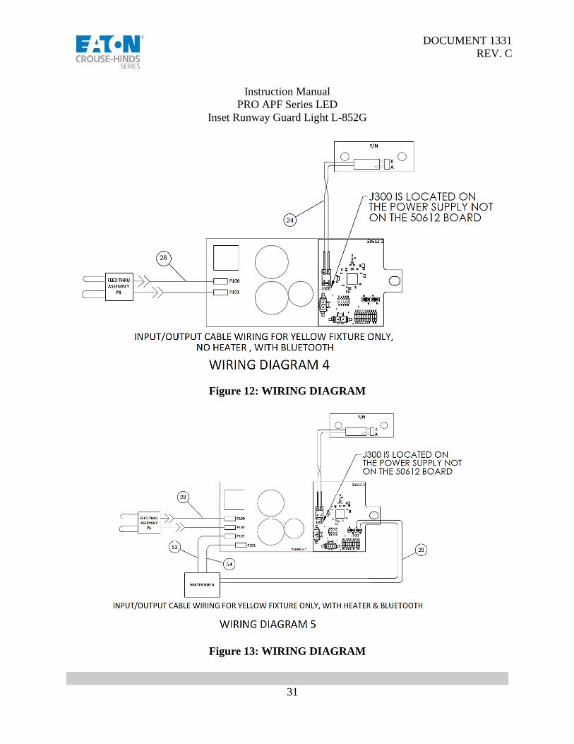
Figure 12: WIRING DIAGRAM
Figure 13: WIRING DIAGRAM

DOCUMENT 1331
REV. C
Instruction Manual
PRO APF Series LED
Inset Runway Guard Light L-852G
32
13 Appendix A: Bluetooth Instruction
Contact Eaton Crouse-Hinds Airport Lighting on Bluetooth App information.
The Fixture Configuration Application is an Android based application that can be used to configure light
fixtures as well as to gather diagnostic information about the fixtures. Section 13.1 provides user
instructions for running the app.
13.1 Running the Application
13.1.1 Running the App and Connecting to a Fixture
Start the Configuration App by clicking the ‘Crouse-Hinds ConfigTool’ the icon. All available fixtures will
be displayed on the screen. Click on ‘Connect’ to connect to fixture.

DOCUMENT 1331
REV. C
Instruction Manual
PRO APF Series LED
Inset Runway Guard Light L-852G
33
13.1.2 Features
The Configuration App has two features; Diagnostics and Configuration. The Diagnostics feature can be
used to gather data about the fixture, while the configuration feature can be used to configure the fixture.
13.1.3 Configuration Feature
In order to run the Configuration feature tap on ‘Configuration’.

DOCUMENT 1331
REV. C
Instruction Manual
PRO APF Series LED
Inset Runway Guard Light L-852G
34
13.1.3.1 First ON/First OFF
Whether the fixture starts blinking as first on or first off can be changed by clicking ‘SET FIRST ON’ or
‘SET FIRST OFF’ button. The change will take effect the next time the light fixture is turned on.
13.1.3.2 Configuration Feature
The phase of the fixture can be changed by clicking ‘SET 0 PHASE’ OR ‘SET 45 PHASE’ button.

DOCUMENT 1331
REV. C
Instruction Manual
PRO APF Series LED
Inset Runway Guard Light L-852G
35
13.1.3.3 Change Ramp Time
The ramp time of the fixture can be changed by clicking ‘DECREASE RAMP’ or ‘INCREASE RAMP’.
13.1.3.4 Toggle Blinking
Blinking can be toggled by clicking the ‘TOGGLE BLINKING’ button. Clicking it once will make the
fixture stay full on; clicking it again will make the fixture blink again.

DOCUMENT 1331
REV. C
Instruction Manual
PRO APF Series LED
Inset Runway Guard Light L-852G
36
13.1.4 Diagnostics Feature
In order to run the Diagnostics feature tap on ‘Diagnostics.
13.1.4.1 Operating Data
The following data is displayed under Operating Data.
• Input Current
• Current Step
• PFC Voltage
• LED Voltage
• LED Current
• 12V Bias Voltage
• Line Frequency
13.1.4.2 Temperature Data
The following data is displayed under Temperature Data.
• Heater Temp
• Heater Max Temp
• MCU Temp
• MCU Max Temp
• MCU Stored Temp

DOCUMENT 1331
REV. C
Instruction Manual
PRO APF Series LED
Inset Runway Guard Light L-852G
37
13.1.4.3 Operating Hours
The following data is displayed under Operating Hours.
• Total Hours
• B1 Hours
• B2 Hours
• B3 Hours
• B10 Hours
• B4 Hours
• B30 Hours
• B5/B100 Hours
13.1.4.4 Error Logs
The following data is displayed under Error Logs.
• PFC OV
• PFC UV
• PFC OC
• 12V Bias
• LED Voltage
• LED DC OC
• LED Peak OC

DOCUMENT 1331
REV. C
Instruction Manual
PRO APF Series LED
Inset Runway Guard Light L-852G
38
13.1.5 Help
The help screen displays helpful information about the Configuration App.