document 2-21(a–c) 591 - history home book p591-6… · · 2005-09-28stream are tracks for an...
TRANSCRIPT

Document 2-21(a–c) 591
engine, but have been unable to make any such tests due to lack of equipment. Agiant wind tunnel might serve to supplant the immediate necessity for securingspecial equipment for testing air-cooled engines.
The study of adjustable and variable pitch propellers is tied up directly withthe power plant problem, especially with the supercharged engine problem. Inlight of present knowledge, it would seem that variable pitch propellers must bedeveloped into safe and efficient units if the ultimate advantages of the super-charged engine are to be realized. In our tests with the Roots supercharger wehave felt a definite need for the variable pitch propeller, especially for high alti-tude operation. These two types of propellers could be carefully studied in a giantwind tunnel, whereas their characteristics could not be investigated efficiently, ifat all, in a small model due to the difficulty of reproducing them to a small scale.
In conclusion, I concur with the general opinion that the tentative size (20 ft.)of the proposed tunnel be increased to such a size as to enable certain of thesmaller size airplanes, or specially built small size airplanes, being tested thereinin toto, and to permit accurate testing of large propellers (we are at present usinga propeller having a diameter of 13 ft.) such as are used with geared engines.
[signed] Arthur W. GardinerArthur W. Gardiner,Assistant Aeronautical EngineerLangley Field, Va.April 23, 1925.
Document 2-21(c), Smith J. DeFrance, The NACA Full-Scale Wind Tunnel, NACA Technical Report No. 459, 1933.
SUMMARYThis report gives a complete description of the full-scale wind tunnel of the National
Advisory Committee for Aeronautics. The tunnel is of the double-return flow type with a 30by 60 foot open jet at the test section. The air is circulated by two propellers 35 feet 5 inch-es in diameter, located side by side, and each directly connected to a 4,000-horsepower slip-ring induction motor. The motor control equipment permits varying the speed in 24 stepsbetween 25 and 118 miles per hour. The tunnel is equipped with a 6-component balancefor obtaining the forces in 3 directions and the moments about the 3 axes of an airplane. Allseven dial scales of the balance system are of the recording type, which permits simultaneousrecords to be made of all forces.
The tunnel has been calibrated and surveys have shown that the dynamic-pressure dis-tribution over that portion of the jet which would be occupied by an airplane having a wingspan of 45 feet is within ± 1 1/2 per cent of a mean value. Based on the mean velocity of118 miles per hour at the jet, the ratio of the kinetic energy per second to the energy input

Chapter 2: Building a Research Establishment592
to the propellers per second is 2.84. Since it is generally recognized that a long open jet isa source of energy loss, the above figure is considered very satisfactory.
Comparative tests on several airplanes have given results which are in good agreementwith those obtained on the same airplanes in flight. This fact, together with informationobtained in the tunnel on Clark Y airfoils, indicates that the flow in the tunnel is satisfac-tory and that the air stream has a very small amount of turbulence.
INTRODUCTIONIt is a generally accepted fact that the aerodynamic characteristics of a small
model can not be directly applied to a full-sized airplane without using an empiricalcorrection factor to compensate for the lack of dynamic similarity. Two methodshave been used to overcome this difficulty. One is to compress the working fluidand vary the kinematic viscosity to compensate for the reduction in the size of themodel. This method is used in the variable-density wind tunnel where tests canbe conducted at the same Reynolds number as would be experienced in flight.The other method is to conduct tests on the full-scale airplane.
The variable-density wind tunnel offers a satisfactory means for testing thecomponent parts of an airplane and is particularly suitable for conducting funda-mental research on airfoil sections and streamline bodies. However, this equipmenthas its limitations when the aerodynamic characteristics of a complete airplaneare desired, especially if the effect of the slipstream is to be considered. It is prac-tically impossible to build a model of the required size that is a true reproductionof a complete airplane. This difficulty is increased by the requirement that themodel withstand large forces.
It is apparent that the most satisfactory method of obtaining aerodynamiccharacteristics of a complete airplane is to conduct a full-scale investigation.Heretofore such investigations have been conducted only in flight. Because of thevariation in atmospheric conditions, it has been necessary to make a large numberof check flights to obtain enough data to average out the discrepancies.Furthermore, in flight testing the scope of experiments is often limited by the factthat the possible alterations that can be made are restricted to those that do notseriously affect the weight or airworthiness of the airplane. In order to provide ameans of full-scale investigation by which the conditions can be controlled andalterations made without serious limitations, the full-scale wind tunnel has beenerected. Of course, only the steady-flight conditions can be readily investigated inthe wind tunnel, but the execution of this work in the tunnel will facilitate full-scaletesting and allow the flight-research personnel of the laboratory to concentrate onthose problems possible of solution only in flight.
The full-scale wind tunnel may be used to determine the lift and drag char-acteristics of a complete airplane, to study the control and stability characteristics

Document 2-21(a–c) 593
both with and without the slipstream, and to study body interference. In addition,equipment has been installed to determine the direction and velocity of the flowat any point around an airplane. Aircraft engine cooling and cowling problemscan also be investigated under conditions similar to those in flight.
The design of the full-scale wind tunnel was started in 1929. Since this was tobe the first wind tunnel constructed with an elliptic throat and with two propellersmounted side by side, a 1/15-scale model was constructed to study the flow problems.Very satisfactory flow conditions were obtained in the model tunnel. This piece ofequipment is now being used for small-scale testing. Construction of the full-scalewind tunnel was started in the spring of 1930; it was completed and operated forthe first time in the spring of 1931.
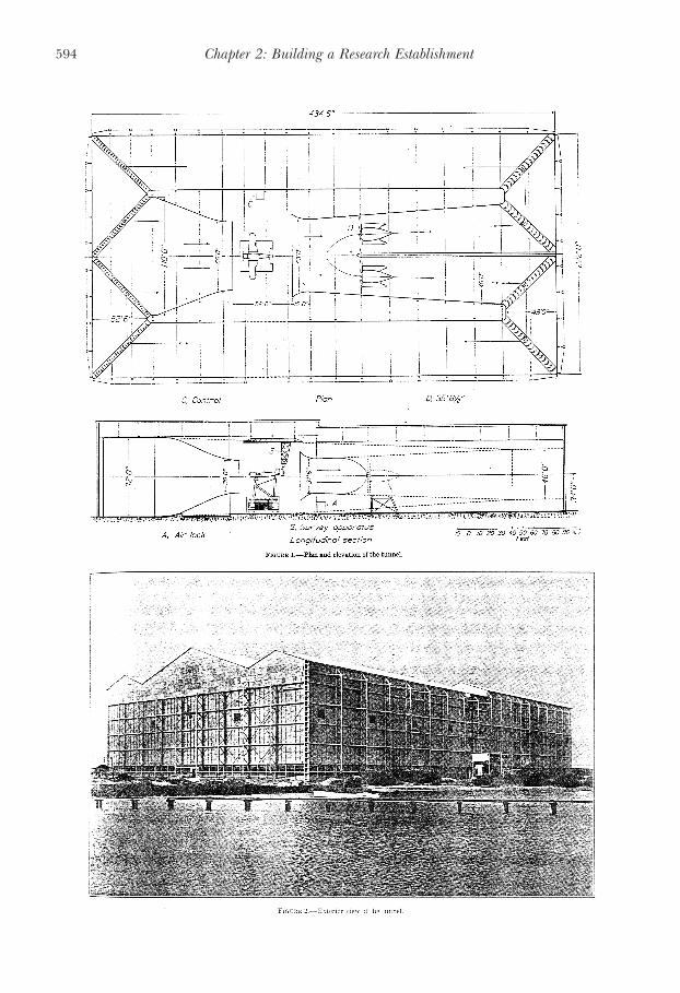
DESCRIPTION OF TUNNELThe general arrangement of the tunnel is shown in figure 1 and an external view
of the building is given in figure 2. The tunnel is of the double-return flow type withan open throat having a horizontal dimension of 60 feet and a vertical dimensionof 30 feet. On either side of the test chamber is a return passage 50 feet wide, withthe, height varying from 46 to 72 feet. The entire equipment is housed in a struc-ture, the outside walls of which serve as the outer walls of the return passages. Theoverall length of the tunnel is 434 feet 6 inches, the width 222 feet, and the max-imum height 97 feet. The framework is of structural steel and the walls and roofare of 5/16-inch corrugated cement asbestos sheets. The entrance and exit conesare constructed of 2-inch wood planking, attached to a steel frame and coveredon the inside with galvanized sheet metal as a protection against fire.
Entrance cone.—The entrance cone is 75 feet in length and in this distancethe cross section changes from a rectangle 72 by 110 feet to a 30 by 60 foot ellipticsection. The area reduction in the entrance cone is slightly less than 5:1. The shapeof the entrance cone was chosen to give as far as possible a constant accelerationto the air stream and to retain a 9-foot length of nozzle for directing the flow.
Test chamber.—The test chamber, in which is located the working section ofthe jet, is 80 by 122 feet. The length of the jet, or the distance between the endof the entrance cone and the smallest cross section of the exit-cone collector, is 71feet. Doors 20 by 40 feet located in the walls of the return passage on one sideprovide access for airplanes. In the roof of the test chamber are two skylights, eachapproximately 30 by 40 feet, which provide excellent lighting conditions for day-time operation; eight 1,000-watt flood lights provide adequate artificial illumina-tion for night operation. Attached to the roof trusses and running across the testchamber at right angles to the air stream and also in the direction of the airstream are tracks for an electric crane which lifts the airplanes onto the balance.
Exit cone.—Forward of the propellers and located on the center line of thetunnel is a smooth fairing which transforms the somewhat elliptic section of the
Chapter 2: Building a Research Establishment594

Document 2-21(a–c) 595
single passage into two circular ones at the propellers. From the propellers aft, theexit cone is divided into two passages and each transforms in the length of 132 feetfrom a 35-foot 6 1/2-inch circular section to a 46-foot square. The included anglebetween the sides of each passage is 6°.
Propellers.—The propellers are located side by side and 48 feet aft of thethroat of the exit-cone bell. The propellers are 35 feet 5 inches in diameter andeach consists of four cast aluminum alloy blades screwed into a cast-steel hub.
Motors.—The most commonly used power plant for operating a wind tunnelis a direct-current motor and motor-generator set with the Ward Leonard controlsystem. For the full-scale wind tunnel it was found that alternating current slip-ring induction motors, together with satisfactory control equipment, could bepurchased for approximately 30 per cent less than the direct-current equipment.Two 4,000-horsepower slip-ring induction motors with 24 steps of speed between75 and 300 r.p.m. were therefore installed. In order to obtain the range of speedone pole change was provided and the other variations are obtained by the intro-duction of resistance in the rotor circuit. This control permits a variation in airspeed from 25 to 118 miles per hour. The two motors are connected through anautomatic switchboard to one drum-type controller located in the test chamber.All the control equipment is interlocked and connected through time-limit relays,so that regardless of how fast the controller handle is moved the motors willincrease in speed at regular intervals.
The motors are provided with ball and roller bearings, which reduce the frictionlosses to a minimum. Roller bearings of 8.5- and 11.8-inch bores are provided atthe slip-ring and propeller ends respectively, while the thrust of the propellers istaken on a ball bearing at the rear end of each motor shaft. The motors aremounted with the rotor shafts centered in the exit-cone passages. The motors andsupporting structure are enclosed in fairings so that they offer a minimum resistanceto the air flow.
Guide vanes.—The air is turned at the four corners of each return passageby guide vanes. The vanes are of the curved-airfoil type formed by two intersectingarcs with a rounded nose. The arcs were so chosen as to give a practically constantarea through the vanes.
The vanes at the first two corners on back of the propellers have chords of 7 feetand are spaced at 0.45 and 0.47 of a chord length, respectively. Those at theopposite end of the tunnel have chords of 3 feet 6 inches and are spaced at 0.41of a chord length. By a proper adjustment of the angular setting of the vanes, asatisfactory velocity distribution has been obtained and no honeycomb has beenfound necessary.
Balance.—The balance, which is of the 6-component type, is shown diagram-matically in figure 3. Ball and socket fittings at the top of each of the struts A hold

Chapter 2: Building a Research Establishment596
the axles of the airplane to be tested; the tail is attached to the triangular frameB. These struts are secured to the turntable C, which is attached to the floatingframe D. This frame rests on the struts E, which transmit the lift forces to thescales F. The drag linkage G is attached to the floating frame on the center lineand, working against a known counterweight H, transmits the drag force to ascale J. The cross-wind force linkages K are attached to the floating frame on thefront and rear sides at the center line. These linkages, working against knowncounterweights L, transmit the cross-wind force to scales M. In this manner forcesin three directions are measured and by combining the forces and the properlever arms, the pitching, rolling, and yawing moments can be computed.

Document 2-21(a–c) 597
The scales are of the dial type and are provided with solenoid-operated printingdevices. When the proper test condition is obtained, a push-button switch is momen-tarily closed and the readings on all seven scales are recorded simultaneously,eliminating the possibility of personal errors.
The triangular frame B is caused to telescope by electrically operated screws whichraises and lowers the tail of the airplane and thereby varies the angle of attack. Bya similar mechanism the turntable C can be moved so as to yaw the airplane from20° left to 20° right.
The entire floating frame and scale assembly is enclosed in a room for protectionfrom air currents and the supporting struts are shielded by streamlined fairings whichare secured to the roof of the balance room and free from the balance. In figure4 it can be seen that very limited amount of the supporting structure is exposed tothe air stream. The tare-drag measurements are therefore reduced to a minimum.
Survey equipment.—Attached to the bottom of the roof trusses is a 55-footstructural steel bridge (fig. 5), which can be rolled across the full width of the testchamber; mounted on this bridge is a car which can be rolled along the entirelength. Suspended below the car is a combined pitot, pitch, and yaw tube whichcan be raised or lowered and pitched or yawed by gearing with electrical control

Chapter 2: Building a Research Establishment598
on the car. This arrangement permits the alinement of the tube with the air flow atany point around an airplane. The alinement of the tube is indicated by null readingson the alcohol manometers connected to the pitch and yaw openings in the headand the angle of pitch or yaw is read from calibrated Veeder counters connectedto the electric operating motors. This equipment is very valuable for studying thedownwash behind wings and the flow around the tail surfaces of an airplane.
CALIBRATIONS AND TESTSThe velocity distribution has been measured over several planes at right
angles to the jet, but the plane representing approximately the location of the wingsof an airplane during tests was most completely explored. The dynamic-pressuredistribution over the area that would be occupied during tests by an airplane witha wing span of 45 feet is within ±1? per cent of a mean value. It is possible toimprove the distribution by further adjustment of the guide vanes. However, testsalready conducted in the tunnel indicate that the present distribution does notdetrimentally affect the results. This fact has been shown by the excellent agreementwhich has been obtained between the tunnel and flight results.
A survey of the static pressure along the axis of the tunnel showed that thelongitudinal pressure gradient is small, as evidenced by the fact that between 11 and
Document 2-21(a–c) 599
36 feet from the entrance cone the variation of the static pressure is within ± 1 percent of the mean dynamic pressure at the test section.
Two wall plates with static orifices are located in each return passage justahead of the guide vanes at the entrance-cone end of the tunnel. The orifices areconnected by a common pressure line, which is led to a micromanometer on thecontrol desk in the test chamber. The other side of the manometer is left open tothe test-chamber pressure. This installation has been calibrated against the averagedynamic pressure determined by pitot surveys of the jet at the test location and itis used to determine the dynamic head during tests.
A series of Clark Y airfoils of the same aspect ratio, but with spans of 12, 24, 36,and 48 feet, have been tested at the same Reynolds number to determine the jet-boundary correction. Tests have also been made to determine the blocking effectof an airplane in the jet. The results of the complete investigation will be present-ed in a separate report.
Using the mean velocity across the jet of 118 miles per hour for computingthe kinetic energy per second at the working section and dividing this by theenergy input to the propellers per second gives an energy ratio for the tunnel of2.84. This ratio, considering the length of the open jet, compares very favorablywith the most efficient open-throat tunnels now in operation and exceeds the effi-ciency expected when the tunnel was designed.

Chapter 2: Building a Research Establishment600
Before force measurements are made on an airplane, the airplane is suspend-ed from the roof trusses by cables and held within one half inch from the balancesupports while the tare forces are measured. The tare-drag coefficient determinedin the above manner has been of the order of 25 per cent of the minimum dragcoefficient of the airplanes tested.
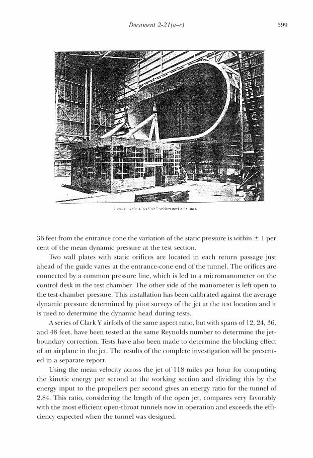
When testing airfoils the airplane supports are replaced by those shown infigure 6. The angle of attack is changed by displacing the rear support arms androtating the airfoil about pins in the top of the main supports. The rear supportarms are moved by linkages, which are connected to long screws on the back ofthe main supports, and the screws are operated by hand cranks inside the balancehouse. The tare drag of this support system is exceptionally small and amounts to

Document 2-21(a–c) 601
only 3 per cent of the minimum drag of a 6 by 36 foot Clark Y airfoil.The lift and drag characteristics have been measured in the tunnel on several
airplanes which had been previously tested in flight and their polars determined.These tests were conducted to obtain a check between the tunnel results and thosefrom flight tests. A comparison of the results from the two methods of testing forone of the airplanes, the Fairchild F-22, is shown in figure 7. The wind-tunnelresults are shown by the solid lines and the flight results are presented by theexperimental points. These curves are representative of the results obtained withthe different airplanes.
The agreement that has been obtained between the flight and full-scale tunnelresults, together with the consistent manner in which measurements can berepeated when check tests are made, has demonstrated the accuracy and value ofthe equipment for aeronautical research.
LANGLEY MEMORIAL AERONAUTICAL LABORATORY,NATIONAL ADVISORY COMMITTEE FOR AERONAUTICS,
LANGLEY FIELD, VA., March 13, 1933.