document #9620-20-d-hbx-03 table of contents
TRANSCRIPT
Manual, Pneumatic and Fluid Module, Hydraulic, HBxDocument #9620-20-D-HBx-03
Pinnacle Park • 1031 Goodworth Drive • Apex, NC 27539 • Tel: 919.772.0115 • Fax: 919.772.8259 • www.ati-ia.com • Email: [email protected] D-1
Table of ContentsD. Pneumatic and Fluid Modules ...............................................................................................D-2HBx Hydraulic Modules ...............................................................................................................D-21. Product Overview ..................................................................................................................D-22. Installation .............................................................................................................................D-4
2.1 Module Installation .................................................................................................................... D-4
2.2 Module Removal ........................................................................................................................ D-5
3. Operation ...............................................................................................................................D-64. Maintenance ...........................................................................................................................D-8
4.1 Preventive Maintenance ........................................................................................................... D-8
5. Troubleshooting and Service Procedures ..........................................................................D-95.1 Troubleshooting ........................................................................................................................ D-9
5.2 Service Procedures ................................................................................................................. D-105.2.1 Coupler Replacement ................................................................................................... D-10
5.2.2 Alignment Pin Replacement ..........................................................................................D-11
5.2.3 Alignment Bushing Replacement ................................................................................. D-12
6. Recommended Spare Parts ................................................................................................D-127. Specifications ......................................................................................................................D-138. Drawings ..............................................................................................................................D-15
8.1 HB2 Hydraulic Module Drawing ............................................................................................. D-15
8.2 HB3 Hydraulic Module Drawing ............................................................................................. D-16
8.3 HB6 Hydraulic Module Drawing ............................................................................................. D-17
8.4 HB8 Hydraulic Module Drawing ............................................................................................. D-18
8.5 HB8ZF2T1 Hydraulic Module Drawing .................................................................................. D-19
8.6 HB9 Hydraulic Module Drawing ............................................................................................. D-20
8.7 HB9ZF2T1 Hydraulic Module Drawing .................................................................................. D-21
8.8 HB10 Hydraulic Module Drawing ........................................................................................... D-22
8.9 HC2 Tool-side Protective Cover Drawing .............................................................................. D-23
8.10 HC4 Tool-side Protective Cover Drawing .............................................................................. D-24
8.11 9630-20-COUPLER .................................................................................................................. D-25

Manual, Pneumatic and Fluid Module, Hydraulic, HBxDocument #9620-20-D-HBx-03
Pinnacle Park • 1031 Goodworth Drive • Apex, NC 27539 • Tel: 919.772.0115 • Fax: 919.772.8259 • www.ati-ia.com • Email: [email protected] D-2
D. Pneumatic and Fluid Modules
HBx Hydraulic Modules1. Product Overview
The HBx modules are modular assemblies adapting commercial, no-drip, self-sealing fluid couplers to the ATI Tool Changers. The modules support multiple connections and are equipped with alignment pins to insure proper engagement of the couplers. The length of the couplers requires that the customer’s robot drive the halves of the module together while monitoring the Tool Changer’s Ready-to-Lock sensors. The customer must use flexible lines for all plumbing connections as hard pipe will not allow proper coupler alignment.
Table 1.1—Hydraulic Modules CouplersModules Connections Tool Side Cover
HB2 modules (2) 3/8” BSPP couplers (1) 1/4” BSPP coupler
HC2-THB3 modules (2) 3/8” BSPP couplersHB6 modules (2) 3/8” BSPP couplersHB8 and HB8ZF2T1 modules (1) 1/4” BSPP couplerHB9 and HB9ZF2T1 modules (2) 1/4” BSPP couplers HC4-T
HB10 modules (2) 3/8” NPT couplers (1) 1/4” NPT coupler HC2-T
Figure 1.1—Hydraulic Module
9121-HB2-M (Shown)
9121-HB2-T (Shown)
Common Ledge Mounting Feature
(2) Alignment Pin
(2) Alignment Bushing
(3) Male (Plug) Coupler
(3) Female (Socket) Coupler
Manual, Pneumatic and Fluid Module, Hydraulic, HBxDocument #9620-20-D-HBx-03
Pinnacle Park • 1031 Goodworth Drive • Apex, NC 27539 • Tel: 919.772.0115 • Fax: 919.772.8259 • www.ati-ia.com • Email: [email protected] D-3
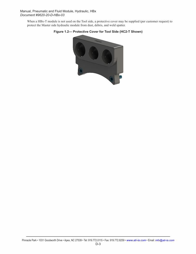
When a HBx-T module is not used on the Tool side, a protective cover may be supplied (per customer request) to protect the Master side hydraulic module from dust, debris, and weld spatter.
Figure 1.2— Protective Cover for Tool Side (HC2-T Shown)

Manual, Pneumatic and Fluid Module, Hydraulic, HBxDocument #9620-20-D-HBx-03
Pinnacle Park • 1031 Goodworth Drive • Apex, NC 27539 • Tel: 919.772.0115 • Fax: 919.772.8259 • www.ati-ia.com • Email: [email protected] D-4
2. InstallationThe fluid modules are typically installed by ATI prior to shipment. The following steps outline the field installation or removal as required.
WARNING: Do not perform maintenance or repair(s) on the Tool Changer or modules unless the Tool is safely supported or placed in the tool stand, all energized circuits (e.g. electrical, air, water, etc.) are turned off, pressurized connections are purged and power is discharged from circuits in accordance with the customer’s safety practices and policies. Injury or equipment damage can occur with the Tool not placed and energized circuits on. Place the Tool in the tool stand, turn off and discharge all energized circuits, purge all pressurized connections, and verify all circuits are de-energized before performing maintenance or repair(s) on the Tool Changer or modules.
CAUTION: Do not use fasteners with pre-applied adhesive more than once. Fasteners might become loose and cause equipment damage. Always apply new thread locker when reusing fasteners.
2.1 Module InstallationTools required: 5 mm Allen Wrench® (hex key)Supplies required: Loctite® 242, clean rag
1. Place the Tool in a secure location.2. Uncouple the Master and Tool plates.3. Turn off and de-energize all energized circuits (e.g. electrical, air, water, etc.).4. It may be necessary to clean the mounting surface on the Tool Changer prior to installing the module in
order to remove any debris that may be present.5. Using the ledge feature, place the module into the appropriate location on the Tool Changer. Align the
module with the Tool Changer using the dowels in the bottom of the ledge feature. Refer to Figure 2.1.6. If fasteners do not have pre-applied adhesive, apply Loctite 242 to the supplied M6 socket head cap
screws.7. Install the (2) M6 socket head screws securing the module to the Tool Changer and tighten to 70 in-lbs
(7.9 Nm).8. Fluid plumbing can be connected to the module after attaching the module to the Tool Changer body.
Ensure that the connectors are cleaned prior to being secured as appropriate. Refer to Figure 1.1.9. After the procedure is complete, resume normal operation.
Manual, Pneumatic and Fluid Module, Hydraulic, HBxDocument #9620-20-D-HBx-03
Pinnacle Park • 1031 Goodworth Drive • Apex, NC 27539 • Tel: 919.772.0115 • Fax: 919.772.8259 • www.ati-ia.com • Email: [email protected] D-5
Figure 2.1—Module Installation
Tool Changer
Common Ledge Mounting Feature
Hydraulic Module (HB2-T Shown)
(2) M6 Socket Head Cap Screw
Connection Side of Couplers
Mating Side of Couplers
Common Ledge Mounting Feature
2.2 Module RemovalTools required: 5 mm Allen Wrench (hex key)
1. Place the Tool in a secure location.2. Uncouple the Master and Tool plates.3. Turn off and de-energize all energized circuits (e.g. electrical, air, water, etc.).1. Prior to removing the module use a marker pen to scribe a line or indication between the Tool Changer
and module body as a reminder where the module is to be re-installed.2. Depending upon the service or repair being done, customer connections up to the module may or may
not need to be disconnected. 3. Remove the socket head cap screws and lift the module from the Tool Changer. Refer to Figure 2.1.

Manual, Pneumatic and Fluid Module, Hydraulic, HBxDocument #9620-20-D-HBx-03
Pinnacle Park • 1031 Goodworth Drive • Apex, NC 27539 • Tel: 919.772.0115 • Fax: 919.772.8259 • www.ati-ia.com • Email: [email protected] D-6
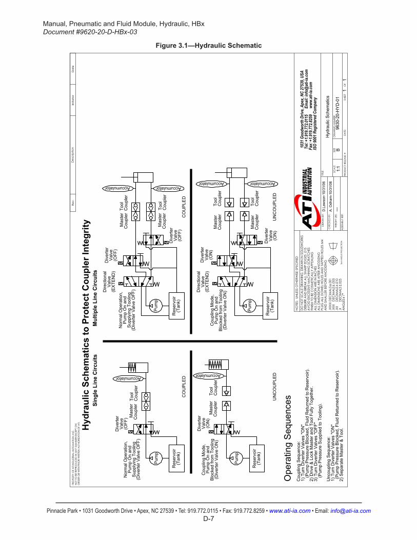
3. OperationThe modules are designed to pass fluids from the Master to the Tool for use by the customer’s tooling.
Liquids are incompressible and therefore coupling lines while pressurized must be avoided. Liquid displaced by mating coupler components creates extremely high pressure spikes and fluid velocities causing seal damage. These problems become more pronounced as the operating pressure is increased.
Figure 3.1 shows simplified schematics for safe, reliable operation of the hydraulic couplers. Contact your hydraulic component distributor for assistance in selecting components compatible with your process and installation. In all liquid coupling applications the customer is advised to take the following steps:
• Plumb the couplers using flexible hoses which are able to absorb pressure spikes and pulses. Highly reinforced hoses and hard pipe must not be used.
• Turn off the supply pump to the circuit and discharge pressure in the lines prior to a tool change.
• Hydraulic pressure accumulators should be installed on both the Master and Tool side plumbing. This is particularly important on the tool side even with the pump turned off and master side pressure discharged.
• During routine maintenance of the Tool Changer the couplers should be inspected and re-lubricated. Water and most solvents will wash away lubricants necessary to prolong seal life.
Failure to follow these steps will result in premature seal failure, jetting of fluid from the couplers during tool changes, and significant pressure pulses in customer tooling.
Manual, Pneumatic and Fluid Module, Hydraulic, HBxDocument #9620-20-D-HBx-03
Pinnacle Park • 1031 Goodworth Drive • Apex, NC 27539 • Tel: 919.772.0115 • Fax: 919.772.8259 • www.ati-ia.com • Email: [email protected] D-7
Figure 3.1—Hydraulic Schematic
11
1:1
B ISO
9001
Reg
ister
ed C
ompa
ny
NO
TES:
UN
LESS
OTH
ERW
ISE
SPEC
IFIE
D
Fax
: +1.9
19.77
2.825
9
www.
ati-i
a.com
Te
l: +1
.919.7
72.01
15
Em
ail: i
nfo@
ati-i
a.com
10
31 G
oodw
orth
Driv
e, Ap
ex, N
C 27
539,
USA
9630
-20-
HY
D-0
1
Hyd
raul
ic S
chem
atic
s
ORD
ER O
R W
ITH P
RIO
R W
RITT
EN A
UTHO
RIZA
TION
OF
ATI.
AN
D S
MA
LLER
BEF
ORE
AN
OD
IZIN
G
DA
TE:
PLUG
ALL
DO
WEL
HO
LES
AN
D T
APP
ED H
OLE
S M
4A
LL D
IMEN
SIO
NS
ARE
AFT
ER A
NO
DIZ
ING
PRO
DUC
T RE
LEA
SE #
ALL
DIM
ENSI
ON
ARE
IN IN
CHE
SFIN
ISH
TO B
E C
OSM
ETIC
ALL
Y A
PPEA
LING
DRA
WIN
G N
UMBE
R
AV
OID
EXC
ESSI
VE
MA
CHI
NIN
G S
CRA
TCHE
SD
EBUR
R A
ND
BRE
AK
ALL
SHA
RP E
DG
ES .0
15
SIZE
DO
NO
T SC
ALE
DRA
WIN
G. D
RAW
N IN
SO
LIDW
ORK
S
1
SCA
LE
SHEE
T
OF
TITLE
3rd
AN
GLE
PRO
JEC
TION
DRA
WN
BY:
CHE
CKE
D B
Y:
WEI
GHT
LBS
:
ASS
EMBL
Y RE
F:
D.L
awso
n-10
/31/
06
A. O
dham
-10/
31/0
6.X
XXX
DEC
IMA
LS.0
01.X
XX
DEC
IMA
LS.0
05.X
X
DEC
IMA
LS.0
10.X
DEC
IMA
LS.0
25A
NG
LES
PRO
PERT
Y O
F A
TI IN
DUS
TRIA
L A
UTO
MA
TION
, IN
C.
NO
T TO
BE
REPR
OD
UCED
IN A
NY
MA
NN
ER E
XCEP
T O
N
---
Nor
mal
Ope
ratio
n,P
ump
On
and
Mas
ter
Cou
pler
Tool
Cou
pler
Tool
Cou
pler
Mas
ter
Accumulator Accumulator
2) S
epar
ate
Mas
ter &
Too
l.
Accumulator
Sing
le L
ine
Circ
uits
Mul
tiple
Lin
e C
ircui
ts
(P
ump
Pre
ssur
e B
lock
ed, F
luid
Ret
urne
d to
Res
ervo
ir).
Cou
pler
Accumulator
Tool
Cou
pler
UN
CO
UP
LED
CO
UP
LED
UN
CO
UP
LED
CO
UP
LED
Unc
oupl
ing
Seq
uenc
e:1)
Tur
n D
iver
ter V
alve
s "O
N"
Tool
Hyd
raul
ic S
chem
atic
s to
Pro
tect
Cou
pler
Inte
grity
(Div
erte
r Val
ve O
N)
Blo
cked
from
Too
ling
Pum
p O
n an
dC
oupl
ing
Mod
e,
(Div
erte
r Val
ve O
FF)
Sup
plyi
ng T
oolin
gP
ump
On
and
(ON
)V
alve
Div
erte
r
(OFF
)V
alve
Div
erte
r
(EX
TEN
D)
Val
ve
Cou
pler
Tool
Cou
pler
Mas
ter
Dire
ctio
nal
Nor
mal
Ope
ratio
n,
(Div
erte
r Val
ve O
N)
Blo
cked
from
Too
ling
Pum
p O
n an
d
(EX
TEN
D)
Val
veD
irect
iona
l
(ON
)V
alve
Div
erte
r
(ON
)V
alve
Cou
pler
Mas
ter
Cou
pler
Mas
ter
(Tan
k)
Pum
p
Res
ervo
irD
iver
ter
(OFF
)V
alve
Cou
pler
Mas
ter
Div
erte
r
(OFF
)
Pum
p
Val
ve
(Tan
k)R
eser
voir
Div
erte
r
Cou
plin
g M
ode,
(Div
erte
r Val
ve O
FF)
Sup
plyi
ng T
oolin
g
(Tan
k)
Pum
p
Res
ervo
ir
(Tan
k)
Pum
pAccumulator
Res
ervo
ir
Cou
pler
Tool
Cou
pler
Accumulator
Ope
ratin
g S
eque
nces
Cou
plin
g S
eque
nce:
1) T
urn
Div
erte
r Val
ves
"ON
"
(Pum
p P
ress
ure
Blo
cked
, Flu
id R
etur
ned
to R
eser
voir)
.2)
Driv
e &
Loc
k M
aste
r and
Too
l Ful
ly T
oget
her.
3) T
urn
Div
erte
r Val
ves
"OFF
"
(Pum
p P
ress
ure
Sup
plie
d to
Too
ling)
.
Rev.
Des
crip
tion
Initi
ato
rD
ate

Manual, Pneumatic and Fluid Module, Hydraulic, HBxDocument #9620-20-D-HBx-03
Pinnacle Park • 1031 Goodworth Drive • Apex, NC 27539 • Tel: 919.772.0115 • Fax: 919.772.8259 • www.ati-ia.com • Email: [email protected] D-8
4. MaintenanceOnce installed, the operation of the modules is generally trouble free. Periodically the condition of the couplers should be checked. Replace any damaged or degraded couplers as necessary. Any contamination in or around the mating surfaces of the modules should be removed with a nylon brush and clean rag. During inspection, ensure that the fasteners attaching the modules to the Tool Changer are secure.
The modules may be field serviced as needed. Maintenance of the modules is simplified if repairs are limited to fitting new coupler halves to the module assemblies. Where the couplers are used to pass water and other fluids that may wash away lubricants, the couplers should be periodically re-lubricated using simple white lithium grease. Refer to Section 4.1—Preventive Maintenance
WARNING: Do not perform maintenance or repair(s) on the Tool Changer or modules unless the Tool is safely supported or placed in the tool stand, all energized circuits (e.g. electrical, air, water, etc.) are turned off, pressurized connections are purged and power is discharged from circuits in accordance with the customer’s safety practices and policies. Injury or equipment damage can occur with the Tool not placed and energized circuits on. Place the Tool in the tool stand, turn off and discharge all energized circuits, purge all pressurized connections, and verify all circuits are de-energized before performing maintenance or repair(s) on the Tool Changer or modules.
4.1 Preventive MaintenanceA visual inspection and preventive maintenance schedule is provided in Table 4.1.
Table 4.1—Preventive Maintenance Schedule ChecklistWeekly Maintenance:
г Clean mating surfaces with nylon brush and clean rag. г Inspect couplers for fluid leaks. Replace couplers as necessary. Refer to Section 5.2.1—Coupler
Replacement. г Inspect alignment pins on the Master module and alignment bushings on the Tool module for
damage or wear, replace as necessary. Refer to Section 5.2.2—Alignment Pin Replacement and Section 5.2.3—Alignment Bushing Replacement.
г Check that module mounting bolts are secure. Refer to Section 2.1—Module Installation.

Manual, Pneumatic and Fluid Module, Hydraulic, HBxDocument #9620-20-D-HBx-03
Pinnacle Park • 1031 Goodworth Drive • Apex, NC 27539 • Tel: 919.772.0115 • Fax: 919.772.8259 • www.ati-ia.com • Email: [email protected] D-9
5. Troubleshooting and Service ProceduresThe following section provides troubleshooting and service information to help diagnose conditions and repair the modules.
WARNING: Do not perform maintenance or repair(s) on the Tool Changer or modules unless the Tool is safely supported or placed in the tool stand, all energized circuits (e.g. electrical, air, water, etc.) are turned off, pressurized connections are purged and power is discharged from circuits in accordance with the customer’s safety practices and policies. Injury or equipment damage can occur with the Tool not placed and energized circuits on. Place the Tool in the tool stand, turn off and discharge all energized circuits, purge all pressurized connections, and verify all circuits are de-energized before performing maintenance or repair(s) on the Tool Changer or modules.
5.1 TroubleshootingRefer to the following table provides troubleshooting information.
Table 5.1—TroubleshootingSymptom Possible Cause Correction
Fluid leakage
Damaged/worn seals Replace coupler halves as needed. Refer to Section 5.2.1—Coupler Replacement.
Debris blocking coupler seal
Clean around couplers. Ensure fluid stream is free of large particulates; filter as necessary.
Bent stem (coupler)
Replace coupler halves as needed. Refer to Section 5.2.1—Coupler Replacement. Tool Changer misalignment could cause stem and alignment pin damage. Check module attachment to Tool Changer. Check robot program and ensure parallel approach trajectory during Tool Changer coupling.
Corrosion Consult ATI for assistance.
Fluid spray during uncoupling
Surge/water hammer
Decrease pressure differential between supply and return lines or install pressure compensation system (e.g., accumulator or surge suppressor as close as possible to spraying port). Refer to Figure 3.1.
Poor flowFlow path blockage Inspect couplers and supply/return lines for blockage, clean/
repair as necessary.Debris blocking coupler seal
Clean around couplers. Ensure fluid stream is free of large particulates; filter as necessary.
Modules won't couple
Bent stem (coupler) or alignment pin
Check module attachment to Tool Changer. Refer to Section 2.1—Module Installation.If alignment components are damaged, replace alignment pins or bushings. Refer to Section 5.2.2—Alignment Pin Replacement or Section 5.2.3—Alignment Bushing Replacement.If stem is bent, replace coupler halves. Refer to Section 5.2.1—Coupler Replacement. Tool Changer misalignment could cause stem and alignment pin damage. Check robot program and ensure parallel approach trajectory during Tool Changer coupling.

Manual, Pneumatic and Fluid Module, Hydraulic, HBxDocument #9620-20-D-HBx-03
Pinnacle Park • 1031 Goodworth Drive • Apex, NC 27539 • Tel: 919.772.0115 • Fax: 919.772.8259 • www.ati-ia.com • Email: [email protected] D-10
5.2 Service ProceduresThe following service procedures provide instructions for component replacement and adjustment.
5.2.1 Coupler ReplacementDuring the warranty period the customer should contact ATI for repair or replacement of these components. After the warranty period the customer may purchase replacement couplers from ATI to perform their own service. The internal construction of the couplers is shown in Section 8.11—9630-20-COUPLER.Parts required: Refer to Section 8—DrawingsTools required: open end wrench, box end wrenchSupplies required: clean rag
1. Place the Tool in a secure location.2. Uncouple the Master and Tool plates.3. Turn off and de-energize all energized circuits (e.g. electrical, air, water, etc.).4. Purge any trapped pressure in the fluid lines and remove the hydraulic lines from the couplers. 5. Each coupler has a mating and connection side (refer to Figure 5.1). The mating side passes
through the module’s aluminum carrier and then receives the connection side which includes the female port for connection of the customer’s fluid lines. Hold the mating side with a box-end wrench while using an open end wrench to remove the connection side by turning the wrench counterclockwise.
6. Discard the removed coupler.7. Using a clean rag, wipe any debris from the coupler mounting surfaces.8. Install the mating side of the new coupler by passing it through the module’s aluminum carrier
and then install the connection side of the new coupler. Hold the mating side with a box end wrench while using an open end wrench to install the connection side by turning the wrench clockwise. Tighten to appropriate torque (refer to Section 8—Drawings).
9. After the procedure is complete, resume normal operation.
Figure 5.1—Coupler Replacement
Hydraulic Module (HB2-M Shown)
Use Box End of Wrench
Use Open End of Wrench
Connection Side of Coupler
Mating Side of Coupler

Manual, Pneumatic and Fluid Module, Hydraulic, HBxDocument #9620-20-D-HBx-03
Pinnacle Park • 1031 Goodworth Drive • Apex, NC 27539 • Tel: 919.772.0115 • Fax: 919.772.8259 • www.ati-ia.com • Email: [email protected] D-11
5.2.2 Alignment Pin ReplacementThe Master side HBx modules include hardened alignment pins. These pins orient the male and female coupler halves correctly during tool changes to prevent damage. Following extended periods of use the pins may wear and need replacement.Parts required: Refer to Section 8—DrawingsTools required: 8 mm open end wrench, box end wrench or adjustable wrench, 5 mm Allen Wrench (hex key)Supplies required: anti-seize compound, Loctite 242, clean rag
1. Place the Tool in a secure location.2. Uncouple the Master and Tool plates.3. Turn off and de-energize all energized circuits (e.g. electrical, air, water, etc.).4. Hold the flats on the alignment pin using a suitable open end or adjustable wrench. Refer to
Figure 5.2.5. Use a 5 mm Allen Wrench to remove the M6 socket head cap screw securing the alignment pin.6. Pull the alignment pin out of the carrier plate and discard.7. Using a clean rag, wipe any debris from the alignment pin mounting surface.8. Apply a thin film of anti-seize compound to the end of the new alignment pin that goes in the
carrier.9. Install the alignment pin.10. Apply Loctite 242 or similar to the M6 socket head cap screw prior to installing. Tighten to
appropriate torque (refer to Section 8—Drawings) while holding the alignment pin with wrench.11. After the procedure is complete, resume normal operation.
Figure 5.2—Alignment Pin Replacement
Hydraulic Module (HB2-M Shown)
Use Open End of Wrench
Connection Side of Module
Mating Side of Module
Alignment Pin
Allen Wrench
M6 Socket Head Cap Screw
to End Prior to InstallationApply Anti-Seize Compound

Manual, Pneumatic and Fluid Module, Hydraulic, HBxDocument #9620-20-D-HBx-03
Pinnacle Park • 1031 Goodworth Drive • Apex, NC 27539 • Tel: 919.772.0115 • Fax: 919.772.8259 • www.ati-ia.com • Email: [email protected] D-12
5.2.3 Alignment Bushing ReplacementThe Tool side HBx modules include hardened bushings to receive the Master side alignment pins. These bushings orient the male and female coupler halves correctly during tool changes to prevent damage. Following extended periods of use the bushings may wear and need replacement.Parts required: Refer to Section 8—DrawingsTools required: 5 mm Allen Wrench® (hex key)
1. Place the Tool in a secure location.2. Uncouple the Master and Tool plates.3. Turn off and de-energize all energized circuits (e.g. electrical, air, water, etc.). 4. Remove the Tool module from the Tool Changer.5. Using a suitably sized drift and an arbor press, press the old bushings out of the carrier.6. Using a suitably sized drift and an arbor press, press the new bushings into of the carrier. Note
that the new bushings should be installed by pressing the chamfered end in first, stopping when the bushing is flush with the top surface of the carrier.
7. After the procedure is complete, resume normal operation.
6. Recommended Spare PartsRefer to Section 8—Drawings..

Manual, Pneumatic and Fluid Module, Hydraulic, HBxDocument #9620-20-D-HBx-03
Pinnacle Park • 1031 Goodworth Drive • Apex, NC 27539 • Tel: 919.772.0115 • Fax: 919.772.8259 • www.ati-ia.com • Email: [email protected] D-13
7. SpecificationsTable 7.1—HB2ModuleSpecifications
Connection Size 3/8” BSPP 1/4” BSPP
Number of Ports 2 1
Cv 1.23 0.46
Pressure Rating Maximum pressure of 2300 psi (158 bar), Self-sealing on Master and Tool
Static Separation Force (created by internal springs) 75 lb (330 N) (force/3 couplers)
Hydraulic Separation Force (per pressurized line)
3/8” BSPP force (lbf) = 0.24 x PSI; (N) = 15.484 x bar
1/4” BSPP force (lbf) = 0.13 x PSI; (N) = 8.387 x bar
Weight Master - 3.24 lbs (1.47 kg) / Tool - 2.87 lbs (1.30 kg)
Table 7.2—HB3ModuleSpecificationsConnection Size 3/8” BSPP
Number of Ports 2
Cv 1.23
Pressure Rating Maximum pressure of 2300 psi (158 bar), Self-sealing on Master and Tool
Static Separation Force (created by internal springs) 56 lb (250 N) (force/2 couplers)
Hydraulic Separation Force (per pressurized line) 3/8” BSPP force (lbf) = 0.24 x PSI; (N) = 15.484 x bar
Weight Master - 3.24 lbs (1.47 kg) / Tool - 2.87 lbs (1.30 kg)
Table 7.3—HB6ModuleSpecificationsConnection Size 3/8” BSPP
Number of Ports 2
Cv 1.23
Pressure Rating Maximum pressure of 7200 psi (496 bar), Self-sealing on Master and Tool
Static Separation Force (created by internal springs) 56 lb (250 N) (force/2 couplers)
Hydraulic Separation Force (per pressurized line) 3/8” BSPP force (lbf) = 0.24 x PSI; (N) = 15.484 x bar
Weight Master - 3.24 lbs (1.47 kg) / Tool - 2.87 lbs (1.30 kg)
Table 7.4—HB8ModuleSpecificationsConnection Size 1/4” BSPP
Number of Ports 1
Cv 0.46
Pressure Rating Maximum pressure of 7200 psi (496 bar), Self-sealing on Master and Tool
Static Separation Force (created by internal springs) 18 lb (80 N) (force/1 coupler)
Hydraulic Separation Force (per pressurized line) 1/4” BSPP force (lbf) = 0.13 x PSI; (N) = 8.387 x bar
Weight Master - 2.23 lbs (1.01 kg) / Tool - 1.86 lbs (0.84 kg)

Manual, Pneumatic and Fluid Module, Hydraulic, HBxDocument #9620-20-D-HBx-03
Pinnacle Park • 1031 Goodworth Drive • Apex, NC 27539 • Tel: 919.772.0115 • Fax: 919.772.8259 • www.ati-ia.com • Email: [email protected] D-14
Table 7.5—HB8ZF2T1ModuleSpecificationsConnection Size 1/4” BSPP
Number of Ports 1
Cv 0.46
Pressure Rating Maximum pressure of 7200 psi (496 bar), Self-sealing on Master and Tool
Static Separation Force (created by internal springs) 18 lb (80 N) (force/1 coupler)
Hydraulic Separation Force (per pressurized line) 1/4” BSPP force (lbf) = 0.13 x PSI; (N) = 8.387 x bar
Weight Master - TBD lbs (TBD kg) / Tool - TBD lbs (TBD kg)
Table 7.6—HB9ModuleSpecificationsConnection Size 1/2” BSPP
Number of Ports 2
Cv 2.26
Pressure Rating Maximum pressure of 7200 psi (496 bar), Self-sealing on Master and Tool
Static Separation Force (created by internal springs) 74 lb (330 N) (force/2 couplers)
Hydraulic Separation Force (per pressurized line) 1/2” BSPP force (lbf) = 0.33 x PSI; (N) = 21.4 x bar
Weight Master - TBD lbs (TBD kg) / Tool - TBD lbs (TBD kg)
Table 7.7—HB9ZF2T1ModuleSpecificationsConnection Size 1/2” BSPP
Number of Ports 2
Cv 2.26
Pressure Rating Maximum pressure of 7200 psi (496 bar), Self-sealing on Master and Tool
Static Separation Force (created by internal springs) 74 lb (330 N) (force/2 couplers)
Hydraulic Separation Force (per pressurized line) 1/2” BSPP force (lbf) = 0.33 x PSI; (N) = 21.4 x bar
Weight Master - TBD lbs (TBD kg) / Tool - TBD lbs (TBD kg)
Table 7.8—HB10ModuleSpecificationsConnection Size 3/8” NPT 1/4” NPT
Number of Ports 2 1
Cv 1.23 0.46
Pressure Rating Maximum pressure of 2300 psi (158 bar), Self-sealing on Master and Tool
Static Separation Force (created by internal springs) 75 lb (330 N) (force/3 couplers)
Hydraulic Separation Force (per pressurized line)
3/8” NPT force (lbf) = 0.24 x PSI; (N) = 15.484 x bar
1/4” NPT force (lbf) = 0.13 x PSI; (N) = 8.387 x bar
Weight Master - TBD lbs (TBD kg) / Tool - TBD lbs (TBD kg)

Manual, Pneumatic and Fluid Module, Hydraulic, HBxDocument #9620-20-D-HBx-03
Pinnacle Park • 1031 Goodworth Drive • Apex, NC 27539 • Tel: 919.772.0115 • Fax: 919.772.8259 • www.ati-ia.com • Email: [email protected] D-15
8. Drawings8.1 HB2 Hydraulic Module Drawing
3rd
AN
GLE
PRO
JEC
TION
5 6
4 5
8 7
3
1
2
SE
E N
OTE
S
(US
E L
OC
TITE
-242
DU
RIN
G IN
STA
LLA
TIO
N)
(AP
PLY
AN
TI-S
EIZ
E C
OM
PO
UN
D T
O P
IN S
HA
NK
BE
FOR
E IN
STA
LLA
TIO
N)
NO
TE 3
160
52.2
41.2
93.5
(CO
UP
LED
)
32.5
31.8
(TY
P.)
51.6
2X G
3/8
(BS
PP
)(M
AS
TER
& T
OO
L)G
1/4
(BS
PP
)(M
AS
TER
& T
OO
L)
HB
2M
AS
TER
HB
2TO
OL
NO
TES
:1)
Cou
pler
s se
para
te in
to fr
ont a
nd re
ar h
alve
s
for i
nsta
llatio
n in
the
carr
iers
/hou
sing
s.2)
Afte
r ins
talla
tion,
torq
ue th
e co
uple
r hal
ves
as fo
llow
s:
1/4
" NP
T C
oupl
ers
= 30
ft-lb
3
/8" N
PT
Cou
pler
s =
44 ft
-lb
NO
LO
CTI
TE3)
Tig
hten
all
M6
SH
CS
to 9
0 in
-lb.
NO
TE 3
NO
TE 3
ITEM
NO
.Q
TY.
PAR
T N
UM
BER
DES
CR
IPTI
ON
11
3405
-122
0009
-01
QD
Plu
g, G
1/4,
230
0 PS
I, Vi
ton
Seal
s2
134
05-1
2200
10-0
1Q
D S
ocke
t, G
1/4,
230
0 PS
I, Vi
ton
Seal
s3
234
05-1
2200
11-0
1Q
D P
lug,
G3/
8, 2
300
PSI,
Vito
n Se
als
42
3405
-122
0012
-01
QD
Soc
ket,
G3/
8, 2
300
PSI,
Vito
n Se
als
54
3500
-106
6016
-15A
M6
x 16
mm
SH
CS
Blu
e D
yed
Mag
ni N
D
Mic
rosp
here
s6
235
00-1
0660
20-1
5AM
6 x
20m
m S
HC
S B
lue
Dye
d M
agni
ND
M
icro
sphe
res
72
3690
-601
3801
-11
25/6
4" B
USH
ING
- M
cMas
ter8
491A
379
82
3700
-20-
4517
Hyd
raul
ic M
odul
e Al
ignm
ent P
in
Rev.
Des
crip
tion
Initi
ator
Dat
e
03EC
O 1
3405
; Rem
oved
900
5-20
-119
8 &
900
5-20
-119
9 C
leat
ass
embl
ies r
epre
sent
atio
ns fr
om d
raw
ing;
Up
dat
ed P
ort c
allo
uts w
ere
1/4
BSPP
& 3
/8 B
SPP
Ports
; Up
dat
ed n
otes
sect
ion;
Ad
ded
Not
e 3
to tw
o ba
lloon
s.TB
C5/
26/2
015
B1:
21
1RE
VISI
ON
NO
TES:
UN
LESS
OTH
ERW
ISE
SPEC
IFIE
D.
DO
NO
T SC
ALE
DRA
WIN
G.
ALL
DIM
ENSI
ON
S A
RE IN
M
ILLIM
ETER
S.
DRA
WN
BY:
CHE
CKE
D B
Y:
D.L
awso
n-5/
25/0
5
J.Sn
ape-
5/26
/05
TITLE SC
ALE
SIZE
DRA
WIN
G N
UMBE
R
PRO
JEC
T #
SHEE
T
O
F 96
30-2
0-H
B205
0523
-103
PRO
PERT
Y O
F A
TI IN
DUS
TRIA
L A
UTO
MA
TION
, IN
C. N
OT
TO B
E RE
PRO
DUC
ED IN
AN
Y M
AN
NER
EXC
EPT
ON
ORD
ER O
R W
ITH P
RIO
R W
RITT
EN A
UTHO
RIZA
TION
OF
ATI.
1031
Goo
dwor
th Dr
ive, A
pex,
NC 27
539,
USA
Tel: +
1.919
.772.0
115
Em
ail: in
fo@ati
-ia.co
mFa
x: +1
.919.7
72.82
59
www
.ati-ia
.com
ISO
9001
Reg
ister
ed C
ompa
ny
HB2
HYD
RAU
LIC
MO
DU
LE S
ERVI
CE
PAR
TS

Manual, Pneumatic and Fluid Module, Hydraulic, HBxDocument #9620-20-D-HBx-03
Pinnacle Park • 1031 Goodworth Drive • Apex, NC 27539 • Tel: 919.772.0115 • Fax: 919.772.8259 • www.ati-ia.com • Email: [email protected] D-16
8.2 HB3 Hydraulic Module Drawing
3rd
AN
GLE
PRO
JEC
TION
3 4
2 3
6 5
1
SE
E N
OTE
S
(US
E L
OC
TITE
-242
DU
RIN
G IN
STA
LLA
TIO
N)
(AP
PLY
AN
TI-S
EIZ
E C
OM
PO
UN
D T
O P
IN S
HA
NK
BE
FOR
E IN
STA
LLA
TIO
N)
160
52.2
41.2
93.5
(CO
UP
LED
)
32.5
31.8
(TY
P.)
51.6
2X G
3/8
(BS
PP
)(M
AS
TER
& T
OO
L)
HB
3M
AS
TER
HB
3TO
OL
NO
TES
:1)
Cou
pler
s se
para
te in
to fr
ont a
nd re
ar h
alve
s
for i
nsta
llatio
n in
the
carr
iers
/hou
sing
s.2)
Afte
r ins
talla
tion,
torq
ue th
e co
uple
r hal
ves
to 4
4 ft-
lb a
nd N
o Lo
ctite
.3)
Tig
hten
all
M6
SH
CS
to 9
0 in
-lb.
NO
TE 3
NO
TE 3
NO
TE 3
ITEM
NO
.Q
TY.
PAR
T N
UM
BER
DES
CR
IPTI
ON
12
3405
-122
0011
-01
QD
Plu
g, G
3/8,
230
0 PS
I, Vi
ton
Seal
s2
234
05-1
2200
12-0
1Q
D S
ocke
t, G
3/8,
230
0 PS
I, Vi
ton
Seal
s3
435
00-1
0660
16-1
5AM
6 x
16m
m S
HC
S B
lue
Dye
d M
agni
ND
M
icro
sphe
res
42
3500
-106
6020
-15A
M6
x 20
mm
SH
CS
Blu
e D
yed
Mag
ni N
D
Mic
rosp
here
s5
236
90-6
0138
01-1
125
/64"
BU
SHIN
G -
McM
aste
r849
1A37
96
237
00-2
0-45
17H
ydra
ulic
Mod
ule
Alig
nmen
t Pin
Rev.
Des
crip
tion
Initi
ator
Dat
e
02EC
O 1
3405
; Rem
oved
900
5-20
-119
8 &
900
5-20
-119
9 C
leat
as
sem
blie
s rep
rese
ntat
ions
from
dra
win
g; U
pdat
ed P
ort
callo
uts w
ere
3/8
BSPP
Por
ts; U
pdat
ed n
otes
sect
ion;
A
dd
ed N
ote
3 to
two
ballo
ons.
TBC
5/26
/201
5
B1:
21
1RE
VISI
ON
NO
TES:
UN
LESS
OTH
ERW
ISE
SPEC
IFIE
D.
DO
NO
T SC
ALE
DRA
WIN
G.
ALL
DIM
ENSI
ON
S A
RE IN
M
ILLIM
ETER
S.
DRA
WN
BY:
CHE
CKE
D B
Y:
J.W
illiam
s 3/
7/06
D.L
awso
n 3/
7/06
TITLE SC
ALE
SIZE
DRA
WIN
G N
UMBE
R
PRO
JEC
T #
SHEE
T
O
F 96
30-2
0-H
B305
0523
-102
PRO
PERT
Y O
F A
TI IN
DUS
TRIA
L A
UTO
MA
TION
, IN
C. N
OT
TO B
E RE
PRO
DUC
ED IN
AN
Y M
AN
NER
EXC
EPT
ON
ORD
ER O
R W
ITH P
RIO
R W
RITT
EN A
UTHO
RIZA
TION
OF
ATI.
1031
Goo
dwor
th Dr
ive, A
pex,
NC 27
539,
USA
Tel: +
1.919
.772.0
115
Em
ail: in
fo@ati
-ia.co
mFa
x: +1
.919.7
72.82
59
www
.ati-ia
.com
ISO
9001
Reg
ister
ed C
ompa
ny
HB3
HYD
RAU
LIC
MO
DU
LE S
ERVI
CE
PAR
TS

Manual, Pneumatic and Fluid Module, Hydraulic, HBxDocument #9620-20-D-HBx-03
Pinnacle Park • 1031 Goodworth Drive • Apex, NC 27539 • Tel: 919.772.0115 • Fax: 919.772.8259 • www.ati-ia.com • Email: [email protected] D-17
8.3 HB6 Hydraulic Module Drawing
3rd
AN
GLE
PRO
JEC
TION
3
4
2 3
9
6
1
SE
E N
OTE
S
(AP
PLY
AN
TI-S
EIZ
E C
OM
PO
UN
D T
O P
IN S
HA
NK
BE
FOR
E IN
STA
LLA
TIO
N)
160
52.2
41.2
93.5
(CO
UP
LED
)
32.5
31.8
(TY
P.)
51.6
(2) 3
/8 B
SP
P(M
AS
TER
& T
OO
L)
HB
6M
AS
TER
HB
6TO
OL
NO
TES
:1)
CO
UP
LER
S S
EP
AR
ATE
INTO
FR
ON
T A
ND
RE
AR
HA
LVE
S
FO
R IN
STA
LLA
TIO
N IN
TH
E C
AR
RIE
RS
/HO
US
ING
S.
ITEM
NO
.Q
TY.
PAR
T N
UM
BER
DES
CR
IPTI
ON
12
3405
-122
0013
-01
QD
Plu
g, G
3/8,
720
0 P
SI,
Vito
n S
eals
22
3405
-122
0014
-01
QD
Soc
ket,
G3/
8, 7
200
PS
I, V
iton
Sea
ls3
435
00-1
0660
16-1
5AM
6 x
16m
m S
HC
S B
lue
Dye
d M
agni
ND
M
icro
sphe
res
42
3500
-106
6020
-15A
M6
x 20
mm
SH
CS
Blu
e D
yed
Mag
ni N
D
Mic
rosp
here
s6
236
90-6
0138
01-1
125
/64"
BU
SHIN
G -
McM
aste
r849
1A37
99
237
00-2
0-45
17H
ydra
ulic
Mod
ule
Alig
nmen
t Pin
Rev.
Des
crip
tion
Initi
ator
Dat
e
04Ec
o 12
754;
Rem
oved
cle
at fr
om H
B6 to
ol si
de.
LJH
7/16
/201
5
B1:
21
1RE
VISI
ON
NO
TES:
UN
LESS
OTH
ERW
ISE
SPEC
IFIE
D.
DO
NO
T SC
ALE
DRA
WIN
G.
ALL
DIM
ENSI
ON
S A
RE IN
M
ILLIM
ETER
S.
DRA
WN
BY:
CHE
CKE
D B
Y:
L.H
ines
8/2
1/08
D.L
awso
n 8/
21/0
8
TITLE SC
ALE
SIZE
DRA
WIN
G N
UMBE
R
PRO
JEC
T #
SHEE
T
O
F 96
30-2
0-H
B605
0523
-104
PRO
PERT
Y O
F A
TI IN
DUS
TRIA
L A
UTO
MA
TION
, IN
C. N
OT
TO B
E RE
PRO
DUC
ED IN
AN
Y M
AN
NER
EXC
EPT
ON
ORD
ER O
R W
ITH P
RIO
R W
RITT
EN A
UTHO
RIZA
TION
OF
ATI.
1031
Goo
dwor
th Dr
ive, A
pex,
NC 27
539,
USA
Tel: +
1.919
.772.0
115
Em
ail: in
fo@ati
-ia.co
mFa
x: +1
.919.7
72.82
59
www
.ati-ia
.com
ISO
9001
Reg
ister
ed C
ompa
ny
HB6
HYD
RAU
LIC
MO
DU
LE S
ERVI
CE
PAR
TS

Manual, Pneumatic and Fluid Module, Hydraulic, HBxDocument #9620-20-D-HBx-03
Pinnacle Park • 1031 Goodworth Drive • Apex, NC 27539 • Tel: 919.772.0115 • Fax: 919.772.8259 • www.ati-ia.com • Email: [email protected] D-18
8.4 HB8 Hydraulic Module Drawing
3rd
AN
GLE
PRO
JEC
TION
3
4 3
6 5
1 2S
EE
NO
TES
Scr
ews
for A
lignm
ent P
ins:
89
lb-in
(App
ly A
nti-S
eize
Com
poun
d to
Pin
Sha
nk B
efor
e In
stal
latio
n)
Scr
ews
for
Mod
ule
Mou
ntin
g:89
lb-in
160
52.2
41.2
93.5
Cou
pled
(App
rox.
)
3/4"
[19]
A
cros
s Fl
ats,
Typ
.
7/8"
[22]
H
ex, T
yp.
12.
1
17.
4
HB
8M
AS
TER HB
8TO
OL
51.6
32.
5
G 1
/4 (B
SP
P)
(Mas
ter &
Too
l)
C L91
21-H
B8-
MM
AS
TER
9121
-HB
8-T
TOO
L
NO
TES
:1)
Cou
pler
s se
para
te in
to fr
ont a
nd re
ar h
alve
s fo
r ins
talla
tion
in c
arrie
rs.
T
ight
en h
alve
s to
30
lb-ft
[40
Nm
] afte
r ins
talla
tion.
2) R
efer
to 9
630-
20-H
YD
for s
afe
oper
atin
g pr
oced
ures
.3)
Ref
er to
963
0-20
-CO
UP
LER
for c
oupl
er m
aint
enan
ce in
stru
ctio
ns.
Rev.
Des
crip
tion
Initi
ator
Dat
e
02EC
O 1
3405
; Rem
oved
900
5-20
-119
8 &
900
5-20
-119
9 C
leat
ass
embl
ies r
epre
sent
atio
ns fr
om d
raw
ing
TBC
5/28
/201
5
ITE
M
NO
.Q
TY.P
AR
T N
UM
BE
RD
ES
CR
IPTI
ON
11
3405
-122
0023
-01
QD
Plu
g, G
1/4,
720
0 P
SI,
Vito
n S
eals
21
3405
-122
0024
-01
QD
Soc
ket,
G1/
4, 7
200
PS
I, V
iton
Sea
ls3
435
00-1
0660
16-1
5AM
6 x
16m
m S
HC
S B
lue
Dye
d M
agni
ND
M
icro
sphe
res
42
3500
-106
6020
-15A
M6
x 20
mm
SH
CS
Blu
e D
yed
Mag
ni N
D
Mic
rosp
here
s5
236
90-6
0138
01-1
125
/64"
BU
SH
ING
- M
cMas
ter8
491A
379
62
3700
-20-
4517
Hyd
raul
ic M
odul
e A
lignm
ent P
in
B1:
21
1RE
VISI
ON
NO
TES:
UN
LESS
OTH
ERW
ISE
SPEC
IFIE
D.
DO
NO
T SC
ALE
DRA
WIN
G.
ALL
DIM
ENSI
ON
S A
RE IN
M
ILLIM
ETER
S.
DRA
WN
BY:
CHE
CKE
D B
Y:
D.L
awso
n-6/
22/1
1
D.S
wan
son-
6/22
/11
TITLE SC
ALE
SIZE
DRA
WIN
G N
UMBE
R
PRO
JEC
T #
SHEE
T
O
F 96
30-2
0-H
B811
0622
-102
PRO
PERT
Y O
F A
TI IN
DUS
TRIA
L A
UTO
MA
TION
, IN
C. N
OT
TO B
E RE
PRO
DUC
ED IN
AN
Y M
AN
NER
EXC
EPT
ON
ORD
ER O
R W
ITH P
RIO
R W
RITT
EN A
UTHO
RIZA
TION
OF
ATI.
1031
Goo
dwor
th Dr
ive, A
pex,
NC 27
539,
USA
Tel: +
1.919
.772.0
115
Em
ail: in
fo@ati
-ia.co
mFa
x: +1
.919.7
72.82
59
www
.ati-ia
.com
ISO
9001
Reg
ister
ed C
ompa
ny
Sing
le G
1/4
Por
t HB
Mod
ule,
720
0 PS
I

Manual, Pneumatic and Fluid Module, Hydraulic, HBxDocument #9620-20-D-HBx-03
Pinnacle Park • 1031 Goodworth Drive • Apex, NC 27539 • Tel: 919.772.0115 • Fax: 919.772.8259 • www.ati-ia.com • Email: [email protected] D-19
8.5 HB8ZF2T1 Hydraulic Module Drawing
3rd
AN
GLE
PRO
JEC
TION
3
4 3
5 6
1 2S
EE
NO
TES
Scr
ews
for A
lignm
ent P
ins:
45
lb-in
(App
ly A
nti-S
eize
Com
poun
d to
Pin
Sha
nk B
efor
e In
stal
latio
n)
Scr
ews
for
Mod
ule
Mou
ntin
g:45
lb-in
160
52.2
41.2
93.5
Cou
pled
(App
rox.
)
7/8"
[22]
H
ex, T
yp.
12.
1
17.
4
HB
8ZF2
T1M
AS
TER
HB
8ZF2
T1TO
OL
51.6
32.
5
G 1
/4 (B
SP
P)
(Mas
ter &
Too
l)
C L91
21-H
B8Z
F2T1
-MM
AS
TER
9121
-HB
8ZF2
T1-T
TOO
L
NO
TES
:C
oupl
ers
sepa
rate
into
fron
t and
rear
hal
ves
for i
nsta
llatio
n in
car
riers
. 1.
Tigh
ten
halv
es to
30
lb-ft
[40
Nm
] afte
r ins
talla
tion.
No
Loct
ite.
Ref
er to
963
0-20
-HY
D fo
r saf
e op
erat
ing
proc
edur
es.
2.R
efer
to 9
630-
20-C
OU
PLE
R fo
r cou
pler
mai
nten
ance
inst
ruct
ions
.3.
Rev.
Des
crip
tion
Initi
ator
Dat
e
ITE
M
NO
.Q
TYP
AR
T N
UM
BE
RD
ES
CR
IPTI
ON
11
3405
-122
0023
-01
QD
Plu
g, G
1/4,
720
0 P
SI,
Vito
n S
eals
21
3405
-122
0024
-01
QD
Soc
ket,
G1/
4, 7
200
PS
I, V
iton
Sea
ls
34
3500
-106
6016
-21A
M6-
1 x
16m
m S
HC
S, S
S, P
re-A
pplie
d4
235
00-1
0660
20-2
1AM
6-1
x 20
mm
SH
CS
, SS
, Pre
-App
lied
52
3700
-20-
4511
Hyd
raul
ic M
odul
e P
re-A
lignm
ent P
in, T
DC
P
late
d
62
3700
-20-
4512
25/6
4" B
ushi
ng, S
teel
, 1.3
8Lg,
5/8
" OD
, TD
C P
late
d
B1:
21
1RE
VISI
ON
NO
TES:
UN
LESS
OTH
ERW
ISE
SPEC
IFIE
D.
DO
NO
T SC
ALE
DRA
WIN
G.
ALL
DIM
ENSI
ON
S A
RE IN
M
ILLIM
ETER
S.
DRA
WN
BY:
CHE
CKE
D B
Y:
D.L
awso
n-4/
3/17
D.W
agne
r-4/1
1/17
TITLE SC
ALE
SIZE
DRA
WIN
G N
UMBE
R
PRO
JEC
T #
SHEE
T
O
F 96
30-2
0-H
B8ZF
2T1
1704
03-1
01
PRO
PERT
Y O
F A
TI IN
DUS
TRIA
L A
UTO
MA
TION
, IN
C. N
OT
TO B
E RE
PRO
DUC
ED IN
AN
Y M
AN
NER
EXC
EPT
ON
ORD
ER O
R W
ITH P
RIO
R W
RITT
EN A
UTHO
RIZA
TION
OF
ATI.
1031
Goo
dwor
th Dr
ive, A
pex,
NC 27
539,
USA
Tel: +
1.919
.772.0
115
Em
ail: in
fo@ati
-ia.co
mFa
x: +1
.919.7
72.82
59
www
.ati-ia
.com
ISO
9001
Reg
ister
ed C
ompa
ny
HB8
ZF2T
1 D
raw
ing,
Sin
gle
7200
PSI
G 1
/4 P
ort,
SS
Har
dwar
e

Manual, Pneumatic and Fluid Module, Hydraulic, HBxDocument #9620-20-D-HBx-03
Pinnacle Park • 1031 Goodworth Drive • Apex, NC 27539 • Tel: 919.772.0115 • Fax: 919.772.8259 • www.ati-ia.com • Email: [email protected] D-20
8.6 HB9 Hydraulic Module Drawing
3rd
AN
GLE
PRO
JEC
TION
4 3
6 5
2S
ee N
ote
1
App
ly a
nti-s
eize
com
poun
d to
th
e pi
n sh
ank
prio
r to
inst
alla
tion.
1
Loct
ite 2
42 /
89 lb
-into
Too
l Cha
nger
Loct
ite 2
42 /
89 lb
-into
Too
l Cha
nger
Loct
ite 2
42 /
89 lb
-in4
HB
9M
AS
TER
HB
9TO
OL
159.
552
.2
41.2
93.5
Cou
pled
(App
rox.
)
73.
1
66
32.5
38.9
(TY
P.)
51.6
2X G
1/2
(BS
PP
)(M
aste
r & T
ool)
HB
9M
AS
TER
HB
9TO
OL
NO
TES
:Th
e co
uple
rs s
epar
ate
into
fron
t and
rear
hal
ves
for i
nsta
llatio
n.
1.A
fter i
nsta
llatio
n, to
rque
the
coup
ler h
alve
s to
51
lb-ft
, NO
LO
CTI
TES
ee 9
630-
20-H
YD
for c
ircui
t plu
mbi
ng in
form
atio
n.2.
See
963
0-20
-CO
UP
LER
for c
oupl
er m
aint
enan
ce in
form
atio
n.3.
Thre
ad lo
cker
Not
e:Fa
sten
ers
on th
is d
raw
ing
incl
ude
both
torq
ue a
nd th
read
lock
er s
peci
ficat
ions
.Th
read
lock
er (L
octit
e) is
onl
y re
quire
d w
hen
re-u
sing
exi
stin
g fa
sten
ers.
New
fast
ener
s fro
m A
TI h
ave
pre-
appl
ied
thre
ad lo
cker
.
ITEM
N
O.
QTY
.PA
RT
NU
MBE
RD
ESC
RIP
TIO
N1
234
05-1
2100
02-0
1Q
D S
ocke
t, G
1/2,
720
0 P
SI,
Vito
n S
eals
22
3405
-121
0003
-01
QD
Plu
g, G
1/2,
720
0 P
SI,
Vito
n S
eals
32
3500
-106
6016
-15A
M6
x 16
mm
SH
CS
Blu
e D
yed
Mag
ni N
D
Mic
rosp
here
s4
435
00-1
0660
20-1
5AM
6 x
20m
m S
HC
S B
lue
Dye
d M
agni
ND
M
icro
sphe
res
52
3690
-601
3801
-11
25/6
4" B
USH
ING
- M
cMas
ter8
491A
379
62
3700
-20-
4517
Hyd
raul
ic M
odul
e Al
ignm
ent P
in
Rev.
Des
crip
tion
Initi
ator
Dat
e
04EC
O 1
3405
; Rem
oved
900
5-20
-119
8 &
900
5-20
-119
9 C
leat
ass
embl
ies r
epre
sent
atio
ns fr
om d
raw
ing
TBC
5/28
/201
5
B1:
31
1RE
VISI
ON
NO
TES:
UN
LESS
OTH
ERW
ISE
SPEC
IFIE
D.
DO
NO
T SC
ALE
DRA
WIN
G.
ALL
DIM
ENSI
ON
S A
RE IN
M
ILLIM
ETER
S.
DRA
WN
BY:
CHE
CKE
D B
Y:
D.L
awso
n-6/
7/12
D.W
agne
r-6/8
/12
TITLE SC
ALE
SIZE
DRA
WIN
G N
UMBE
R
PRO
JEC
T #
SHEE
T
O
F 96
30-2
0-H
B912
0601
-104
PRO
PERT
Y O
F A
TI IN
DUS
TRIA
L A
UTO
MA
TION
, IN
C. N
OT
TO B
E RE
PRO
DUC
ED IN
AN
Y M
AN
NER
E9C
EPT
ON
ORD
ER O
R W
ITH P
RIO
R W
RITT
EN A
UTHO
RIZA
TION
OF
ATI.
1031
Goo
dwor
th Dr
ive, A
pe9,
NC 27
539,
USA
Tel: +
1.919
.772.0
115
Em
ail: in
fo@ati
-ia.co
mFa
9: +1
.919.7
72.82
59
www
.ati-ia
.com
ISO
9001
Reg
ister
ed C
ompa
ny
HB9
Hyd
raul
ic M
odul
e D
raw
ing

Manual, Pneumatic and Fluid Module, Hydraulic, HBxDocument #9620-20-D-HBx-03
Pinnacle Park • 1031 Goodworth Drive • Apex, NC 27539 • Tel: 919.772.0115 • Fax: 919.772.8259 • www.ati-ia.com • Email: [email protected] D-21
8.7 HB9ZF2T1 Hydraulic Module Drawing
3rd
AN
GLE
PRO
JEC
TION
4 3
5 6
2S
ee N
ote
1
App
ly a
nti-s
eize
com
poun
d to
th
e pi
n sh
ank
prio
r to
inst
alla
tion.
1
Loct
ite 2
42 /
45 lb
-into
Too
l Cha
nger
Loct
ite 2
42 /
45 lb
-into
Too
l Cha
nger
Loct
ite 2
42 /
45 lb
-in4
HB
9ZF2
T1M
AS
TER
HB
9ZF2
T1TO
OL
159.
552
.2
41.2
93.5
Cou
pled
(App
rox.
)
73.
1
66
32.5
38.9
(TY
P.)
51.6
2X G
1/2
(BS
PP
)(M
aste
r & T
ool)
HB
9ZF2
T1M
AS
TER
HB
9ZF2
T1TO
OL
NO
TES
:Th
e co
uple
rs s
epar
ate
into
fron
t and
rear
hal
ves
for i
nsta
llatio
n.
1.A
fter i
nsta
llatio
n, to
rque
the
coup
ler h
alve
s to
51
lb-ft
, NO
LO
CTI
TES
ee 9
630-
20-H
YD
for c
ircui
t plu
mbi
ng in
form
atio
n.2.
See
963
0-20
-CO
UP
LER
for c
oupl
er m
aint
enan
ce in
form
atio
n.3.
Thre
ad lo
cker
Not
e:Fa
sten
ers
on th
is d
raw
ing
incl
ude
both
torq
ue a
nd th
read
lock
er s
peci
ficat
ions
.Th
read
lock
er (L
octit
e) is
onl
y re
quire
d w
hen
re-u
sing
exi
stin
g fa
sten
ers.
New
fast
ener
s fro
m A
TI h
ave
pre-
appl
ied
thre
ad lo
cker
.
Rev.
Des
crip
tion
Initi
ator
Dat
e
02EC
O 1
3405
; Rem
oved
900
5-20
-187
7 &
900
5-20
-187
8 C
leat
ass
embl
ies r
epre
sent
atio
ns fr
om d
raw
ing.
TB
C6/
15/2
015
ITEM
N
O.
QTY
.PA
RT
NU
MBE
RD
ESC
RIP
TIO
N1
234
05-1
2100
02-0
1Q
D S
ocke
t, G
1/2,
720
0 P
SI,
Vito
n S
eals
22
3405
-121
0003
-01
QD
Plu
g, G
1/2,
720
0 P
SI,
Vito
n S
eals
32
3500
-106
6016
-21A
M6
x 16
mm
SH
CS
, SS
, ND
Mic
rosp
here
s4
435
00-1
0660
20-2
1AM
6 x
20m
m S
HC
S S
S, N
D M
icro
sphe
res
52
3700
-20-
4511
Hyd
raul
ic M
odul
e P
re-A
lignm
ent P
in, T
DC
Pla
ted
62
3700
-20-
4512
25/6
4" B
ushi
ng, S
teel
, 1.3
8Lg,
5/8
" OD
, TD
C P
late
d
B1:
31
1RE
VISI
ON
NO
TES:
UN
LESS
OTH
ERW
ISE
SPEC
IFIE
D.
DO
NO
T SC
ALE
DRA
WIN
G.
ALL
DIM
ENSI
ON
S A
RE IN
M
ILLIM
ETER
S.
DRA
WN
BY:
CHE
CKE
D B
Y:
D.L
awso
n-7/
11/1
2
D.W
agne
r-7/1
1/12
TITLE SC
ALE
SIZE
DRA
WIN
G N
UMBE
R
PRO
JEC
T #
SHEE
T
O
F 96
30-2
0-H
B9ZF
2T1
1206
01-1
02
PRO
PERT
Y O
F A
TI IN
DUS
TRIA
L A
UTO
MA
TION
, IN
C. N
OT
TO B
E RE
PRO
DUC
ED IN
AN
Y M
AN
NER
E9C
EPT
ON
ORD
ER O
R W
ITH P
RIO
R W
RITT
EN A
UTHO
RIZA
TION
OF
ATI.
1031
Goo
dwor
th Dr
ive, A
pe9,
NC 27
539,
USA
Tel: +
1.919
.772.0
115
Em
ail: in
fo@ati
-ia.co
mFa
9: +1
.919.7
72.82
59
www
.ati-ia
.com
ISO
9001
Reg
ister
ed C
ompa
ny
HB9
ZF2T
1 H
ydra
ulic
Mod
ule
Dra
win
g

Manual, Pneumatic and Fluid Module, Hydraulic, HBxDocument #9620-20-D-HBx-03
Pinnacle Park • 1031 Goodworth Drive • Apex, NC 27539 • Tel: 919.772.0115 • Fax: 919.772.8259 • www.ati-ia.com • Email: [email protected] D-22
8.8 HB10 Hydraulic Module Drawing
3rd
AN
GLE
PRO
JEC
TION
6
15
8 7
24 3
App
ly a
nti-s
eize
com
poun
d to
the
pin
shan
k pr
ior t
o in
stal
latio
n.
Loct
ite-2
42 /
89 lb
-into
Too
l Cha
nger
Not
e 1
Not
e 1
HB
10M
aste
r
HB
10To
ol
5Lo
ctite
-242
/ 89
lb-in
160
52.2
41.2
93.5
Cou
pled
(App
rox.
)
66
59.
9
51.6
32.
5
31.
8 (T
yp.)
2X 3
/8" N
PT
(Mas
ter &
Too
l)1/
4" N
PT
(Mas
ter &
Too
l)
HB
10M
AS
TER
HB
10TO
OL
Thre
ad lo
cker
Not
e:Fa
sten
ers
on th
is d
raw
ing
incl
ude
both
torq
ue a
nd th
read
lock
er s
peci
ficat
ions
.Th
read
lock
er (L
octit
e) is
onl
y re
quire
d w
hen
re-u
sing
exi
stin
g fa
sten
ers.
New
fast
ener
s fro
m A
TI h
ave
pre-
appl
ied
thre
ad lo
cker
.
NO
TES
:Th
e co
uple
rs s
epar
ate
into
fron
t and
rear
hal
ves
for i
nsta
llatio
n.
1.A
fter i
nsta
llatio
n, to
rque
the
coup
ler h
alve
s as
follo
ws:
1/4"
NP
T C
oupl
ers
= 30
lb-ft
3/8"
NP
T C
oupl
ers
= 44
lb-ft
NO
LO
CTI
TES
ee 9
630-
20-H
YD
for c
ircui
t plu
mbi
ng in
form
atio
n.2.
See
963
0-20
-CO
UP
LER
for c
oupl
er m
aint
enan
ce in
form
atio
n.3.
ITEM
N
O.
QTY
.PA
RT
NU
MBE
RD
ESC
RIP
TIO
N1
234
05-1
2200
25-0
1Q
D S
ocke
t, 3/
8 N
PT,
230
0 P
SI,
Vito
n S
eals
22
3405
-122
0026
-01
QD
Plu
g, 3
/8 N
PT,
230
0 P
SI,
Vito
n S
eals
31
3405
-122
0027
-01
QD
Soc
ket,
1/4
NP
T, 2
300
PS
I, V
iton
Sea
ls4
134
05-1
2200
28-0
1Q
D P
lug,
1/4
NP
T, 2
300
PS
I, V
iton
Sea
ls5
435
00-1
0660
16-1
5AM
6 x
16m
m S
HC
S B
lue
Dye
d M
agni
ND
Mic
rosp
here
s6
235
00-1
0660
20-1
5AM
6 x
20m
m S
HC
S B
lue
Dye
d M
agni
ND
Mic
rosp
here
s7
236
90-6
0138
01-1
125
/64"
BU
SHIN
G -
McM
aste
r849
1A37
98
237
00-2
0-45
17H
ydra
ulic
Mod
ule
Alig
nmen
t Pin
Rev.
Des
crip
tion
Initi
ator
Dat
e
02EC
O 1
3405
; Rem
oved
900
5-20
-119
8 &
900
5-20
-119
9 C
leat
ass
embl
ies r
epre
sent
atio
ns fr
om d
raw
ing.
TBC
5/26
/201
5
B1:
31
1RE
VISI
ON
NO
TES:
UN
LESS
OTH
ERW
ISE
SPEC
IFIE
D.
DO
NO
T SC
ALE
DRA
WIN
G.
ALL
DIM
ENSI
ON
S A
RE IN
M
ILLIM
ETER
S.
DRA
WN
BY:
CHE
CKE
D B
Y:
D.L
awso
n-6/
15/1
2
D.W
agne
r-6/1
8/12
TITLE SC
ALE
SIZE
DRA
WIN
G N
UMBE
R
PRO
JEC
T #
SHEE
T
O
F 96
30-2
0-H
B10
1206
15-1
02
PRO
PERT
Y O
F A
TI IN
DUS
TRIA
L A
UTO
MA
TION
, IN
C. N
OT
TO B
E RE
PRO
DUC
ED IN
AN
Y M
AN
NER
EXC
EPT
ON
ORD
ER O
R W
ITH P
RIO
R W
RITT
EN A
UTHO
RIZA
TION
OF
ATI.
1031
Goo
dwor
th Dr
ive, A
pex,
NC 27
539,
USA
Tel: +
1.919
.772.0
115
Em
ail: in
fo@ati
-ia.co
mFa
x: +1
.919.7
72.82
59
www
.ati-ia
.com
ISO
9001
Reg
ister
ed C
ompa
ny
HB1
0 H
YDR
AULI
C M
OD
ULE

Manual, Pneumatic and Fluid Module, Hydraulic, HBxDocument #9620-20-D-HBx-03
Pinnacle Park • 1031 Goodworth Drive • Apex, NC 27539 • Tel: 919.772.0115 • Fax: 919.772.8259 • www.ati-ia.com • Email: [email protected] D-23
8.9 HC2 Tool-side Protective Cover Drawing
3rd
AN
GLE
PRO
JEC
TION
Not
es:
M6
x 16
mm
SH
CS
Blu
e D
yed
Mag
ni N
D
2. I
f Fitt
ing
to T
ool C
hang
er, P
re /
50 in
-lb.
1. B
ag L
oose
item
s if
for i
nven
tory
.
2M
icro
sphe
res
235
00-1
0660
16-1
5AH
B S
erie
s P
rote
ctiv
e P
late
137
00-2
0-60
41
ITEM
N
O.
QTY
.PA
RT
NU
MBE
RD
ESC
RIP
TIO
N
1
Rev.
Des
crip
tion
Initi
ator
Dat
e
02Re
lea
se, N
o C
hang
esD
KL11
/7/2
011
1RE
VIS
ION
NO
TES:
UN
LESS
OTH
ERW
ISE
ALL
DIM
ENSI
ON
S A
RE IN
MA
NN
ER E
XCEP
T O
N O
RDER
OR
WITH
PRI
OR
WRI
TTEN
AUT
HORI
ZATIO
N O
F A
TI.
ISO
9001
Reg
ister
ed C
ompa
ny
1
SPEC
IFIE
D.
DO
NO
T SC
ALE
DRA
WIN
G.
PRO
JEC
T #
SHEE
T
O
F 91
21-H
C2-
T---
02
PRO
PERT
Y O
F A
TI IN
DUS
TRIA
L A
UTO
MA
TION
, IN
C. N
OT
TO B
E RE
PRO
DUC
ED IN
AN
Y M
ILLIM
ETER
S.
DRA
WN
BY:
CHE
CKE
D B
Y:
D.L
awso
n-7/
8/09
D.S
wan
son-
7/8/
09
TITLE SC
ALE
SIZE B
1:1
DRA
WIN
G N
UMBE
R
1031
Goo
dwor
th D
rive,
Apex
, NC
2753
9, US
ATe
l: +1
.919.7
72.01
15
Em
ail: i
nfo@
ati-i
a.com
Fax:
+1.91
9.772
.8259
w
ww.at
i-ia.c
om
HB
Mod
ule
Prot
ectiv
e C
over
Ass
embl
y
2
1
See
Not
es
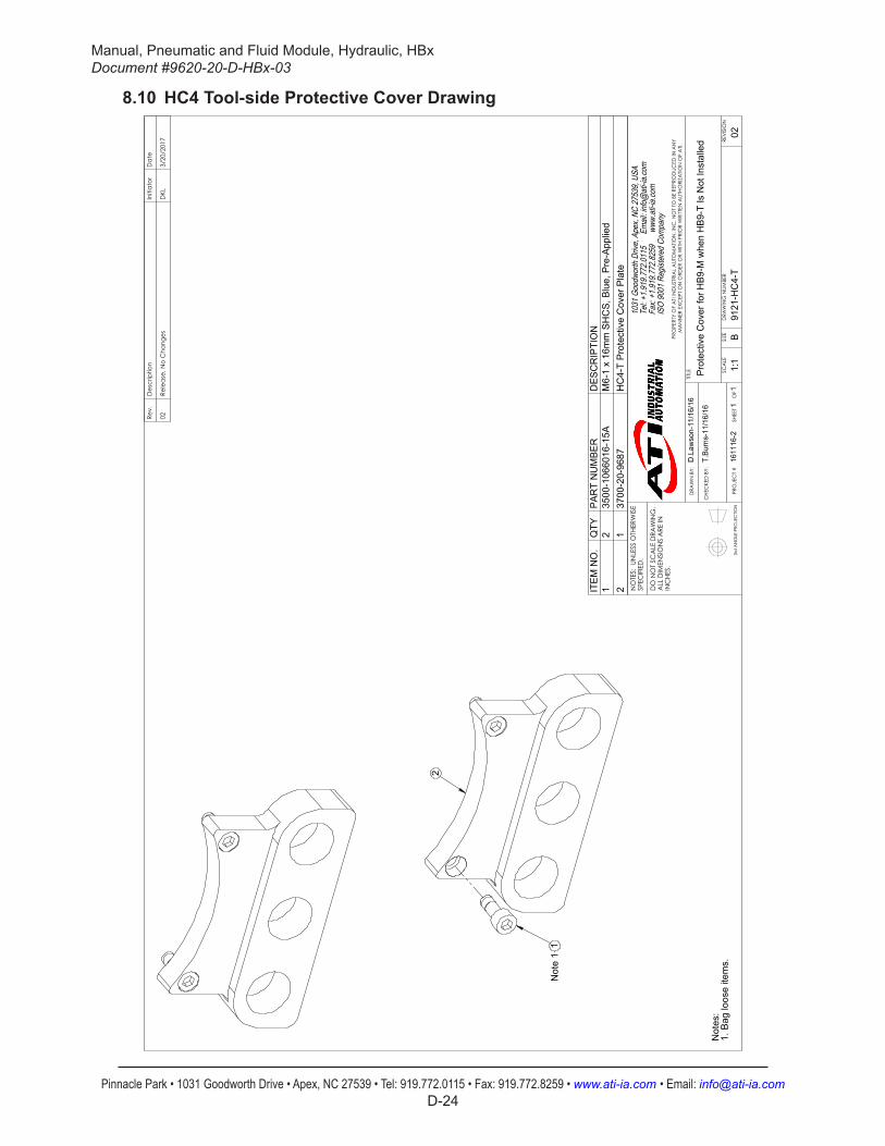
Manual, Pneumatic and Fluid Module, Hydraulic, HBxDocument #9620-20-D-HBx-03
Pinnacle Park • 1031 Goodworth Drive • Apex, NC 27539 • Tel: 919.772.0115 • Fax: 919.772.8259 • www.ati-ia.com • Email: [email protected] D-24
8.10 HC4 Tool-side Protective Cover Drawing
3rd
AN
GLE
PRO
JEC
TION
2
1N
ote
1
Not
es:
Bag
loos
e ite
ms.
1.
Rev.
Des
crip
tion
Initi
ator
Dat
e
02Re
leas
e, N
o C
hang
esD
KL3/
20/2
017
ITE
M N
O.
QTY
PA
RT
NU
MB
ER
DE
SC
RIP
TIO
N1
235
00-1
0660
16-1
5AM
6-1
x 16
mm
SH
CS
, Blu
e, P
re-A
pplie
d2
137
00-2
0-96
87H
C4-
T P
rote
ctiv
e C
over
Pla
te
B1:
11
1RE
VISI
ON
NO
TES:
UN
LESS
OTH
ERW
ISE
SPEC
IFIE
D.
DO
NO
T SC
ALE
DRA
WIN
G.
ALL
DIM
ENSI
ON
S A
RE IN
IN
CHE
S.
DRA
WN
BY:
CHE
CKE
D B
Y:
D.L
awso
n-11
/16/
16
T.Bu
rns-
11/1
6/16
TITLE SC
ALE
SIZE
DRA
WIN
G N
UMBE
R
PRO
JEC
T #
SHEE
T
O
F 91
21-H
C4-
T16
1116
-202
PRO
PERT
Y O
F A
TI IN
DUS
TRIA
L A
UTO
MA
TION
, IN
C. N
OT
TO B
E RE
PRO
DUC
ED IN
AN
Y M
AN
NER
EXC
EPT
ON
ORD
ER O
R W
ITH P
RIO
R W
RITT
EN A
UTHO
RIZA
TION
OF
ATI.
1031
Goo
dwor
th Dr
ive, A
pex,
NC 27
539,
USA
Tel: +
1.919
.772.0
115
Em
ail: in
fo@ati
-ia.co
mFa
x: +1
.919.7
72.82
59
www
.ati-ia
.com
ISO
9001
Reg
ister
ed C
ompa
ny
Prot
ectiv
e C
over
for H
B9-M
whe
n H
B9-T
Is N
ot In
stal
led
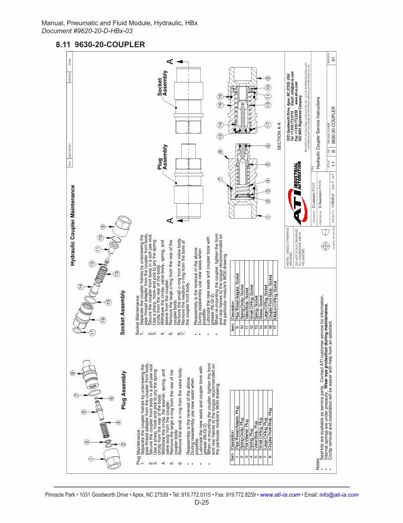
Manual, Pneumatic and Fluid Module, Hydraulic, HBxDocument #9620-20-D-HBx-03
Pinnacle Park • 1031 Goodworth Drive • Apex, NC 27539 • Tel: 919.772.0115 • Fax: 919.772.8259 • www.ati-ia.com • Email: [email protected] D-25
8.11 9630-20-COUPLER
17 So
ck
et
As
se
mb
ly
91
01
1
12
13
14
15
16
So
cke
t M
ain
ten
an
ce
:S
ep
ara
te t
he
co
up
ler
ha
lve
s b
y u
nscre
win
g t
he
1
.p
ipe
th
rea
d a
da
pte
r fr
om
th
e c
ou
ple
r fr
on
t b
od
y.
Se
cu
re t
he
co
up
ler
fro
nt
bo
dy in
a s
oft
-ja
w v
ice
.2
.U
se
a s
ha
rp,
ho
ok-e
nd
pic
k t
o p
ry t
he
sp
rin
g
3.
cir
clip
fro
m t
he
re
ar
of
the
bo
dy.
With
dra
w t
he
cir
clip
, va
lve
bo
dy,
sp
rin
g,
an
d
4.
sle
eve
fro
m t
he
co
up
ler.
Re
mo
ve
th
e la
rge
o-r
ing
fro
m t
he
re
ar
of
the
5
.co
up
ler
bo
dy.
Re
mo
ve
th
e s
ma
ll o
-rin
g f
rom
th
e v
alv
e b
od
y.
6.
Re
mo
ve
th
e m
ed
ium
o-r
ing
fro
m t
he
bo
re o
f7
.th
e c
ou
ple
r fr
on
t b
od
y.
Re
asse
mb
ly is t
he
re
ve
rsa
l o
f th
e a
bo
ve
.
•D
uri
ng
re
asse
mb
ly u
se
ne
w s
ea
ls w
he
n
•p
ossib
le.
Lu
bri
ca
te t
he
ne
w s
ea
ls a
nd
co
up
ler
bo
re w
ith
•
gre
ase
(N
LG
I-2
)W
he
n r
e-m
ou
ntin
g t
he
co
up
ler,
tig
hte
n t
he
fro
nt
•a
nd
re
ar
ha
lve
s t
o t
he
to
rqu
e r
eco
mm
en
de
d o
nth
e p
art
icu
lar
mo
du
le's
96
30
dra
win
g.
.•
Cir
clip
re
mo
va
l a
nd
in
sta
llatio
n w
ill b
e e
asie
r w
ith
he
lp f
rom
an
assis
tan
t.
Hy
dra
uli
c C
ou
ple
r M
ain
ten
an
ce
•No
tes: Se
al kits a
re a
va
ilab
le a
s s
erv
ice
pa
rts.
Co
nta
ct
AT
I cu
sto
me
r se
rvic
e f
or
info
rma
tio
n.
•In
tern
al sp
rin
gs a
re u
nd
er
pre
ssu
re.
We
ar
ey
e p
rote
cti
on
du
rin
g m
ain
ten
an
ce
B1:1
11
D.L
aw
so
n-7
/1/1
1
D.S
wa
nso
n-7
/1/1
1
9630-2
0-C
OU
PLE
R110
63
0-2
01
Hydra
ulic
Couple
r S
erv
ice Instr
uctions
Plu
gA
ss
em
bly
So
ck
et
As
se
mb
lyA
A
15
16
SE
CT
ION
A-A
34
56
78
21
91
01
11
71
3
14
12
8
Plu
g A
ss
em
bly
1
2
3
4
5
6
7
Plu
g M
ain
ten
an
ce
:S
ep
ara
te t
he
co
up
ler
ha
lve
s b
y u
nscre
win
g t
he
1
.p
ipe
th
rea
d a
da
pte
r fr
om
th
e c
ou
ple
r fr
on
t b
od
y.
Se
cu
re t
he
co
up
ler
fro
nt
bo
dy in
a s
oft
-ja
w v
ice
.2
.U
se
a s
ha
rp,
ho
ok-e
nd
pic
k t
o p
ry t
he
sp
rin
g
3.
cir
clip
fro
m t
he
re
ar
of
the
bo
dy.
With
dra
w t
he
cir
clip
, fla
t w
ash
er,
sp
rin
g,
an
d
4.
va
lve
bo
dy f
rom
th
e c
ou
ple
r.R
em
ove
th
e la
rge
o-r
ing
fro
m t
he
re
ar
of
the
5
.co
up
ler
bo
dy.
Re
mo
ve
th
e s
ma
ll o
-rin
g f
rom
th
e v
alv
e b
od
y.
6.
Re
asse
mb
ly is t
he
re
ve
rsa
l o
f th
e a
bo
ve
.
•D
uri
ng
re
asse
mb
ly u
se
ne
w s
ea
ls w
he
n
•p
ossib
le.
Lu
bri
ca
te t
he
ne
w s
ea
ls a
nd
co
up
ler
bo
re w
ith
•
gre
ase
(N
LG
I-2
)W
he
n r
e-m
ou
ntin
g t
he
co
up
ler,
tig
hte
n t
he
fro
nt
•a
nd
re
ar
ha
lve
s t
o t
he
to
rqu
e r
eco
mm
en
de
d o
nth
e p
art
icu
lar
mo
du
le's
96
30
dra
win
g.
Item
Description
1Pip
e T
hre
ad A
dapte
r, P
lug
2Spring C
irclip
, Plu
g
3Fla
t W
asher, P
lug
4Spring, Plu
g
5Valve B
ody, Plu
g
6Sm
all
O-R
ing, Plu
g
7Larg
e O
-Rin
g, Plu
g
8Couple
r Fro
nt Body, Plu
g
Item
Description
9Pip
e T
hre
ad A
dapte
r, S
ocket
10
Spring C
irclip
, Socket
11
Valve B
ody, Socket
12
Sm
all
O-R
ing, Socket
13
Spring, Socket
14
Sle
eve
, Socket
15
Larg
e O
-Rin
g, Socket
16
Couple
r Fro
nt Body, Socket
17
Mediu
m O
-Rin
g, Socket