document de travail 2013-003 - université laval · in the next section we provide the mission of...
TRANSCRIPT

Publié par : Published by: Publicación de la:
Faculté des sciences de l’administration 2325, rue de la Terrasse Pavillon Palasis-Prince, Université Laval Québec (Québec) Canada G1V 0A6 Tél. Ph. Tel. : (418) 656-3644 Télec. Fax : (418) 656-7047
Édition électronique : Electronic publishing: Edición electrónica:
Marylène Paradis Vice-décanat à la recherche Faculté des sciences de l’administration
Disponible sur Internet : Available on Internet Disponible por Internet :
http://www4.fsa.ulaval.ca/cms/site/fsa/accueil/recherche/publications/documentsdetravail [email protected]
DOCUMENT DE TRAVAIL 2013-003 Functional Design of Physical Internet Facilities: A Unimodal Road-Based Crossdocking Hub Benoit MONTREUIL Russell D. MELLER Collin THIVIERGE Zachary MONTREUIL Document de travail également publié par le Centre interuniversitaire de recherche sur les réseaux d’entreprise, la logistique et le transport, sous le numéro CIRRELT-2013-15
Version originale : Original manuscript: Version original:
ISBN – 978-2-89524-386-1
Série électronique mise à jour : On-line publication updated : Seria electrónica, puesta al dia
03-2013

Functional Design of Physical Internet Facilities: A Unimodal Road-Based Crossdocking hub
Benoit Montreuil, Russell D. Meller, Collin Thivierge and Zachary Montreuil
1CIRRELT, Université Laval 2CELDi, University of Arkansas
The content of this document is to be published as a chapter of the book ‘Progress in Material Handling Research 2012’ edited by B. Montreuil, A. Carrano, M.M.R. de Kostner, K.R. Gue, M. Ogle, J. Smith, to be published by MHIA, Charlotte, NC, U.S.A. 2012
ABSTRACT
As part of the 2010 IMHRC, Montreuil, Meller and Ballot proposed a set of facility types that would be necessary to operate a Physical Internet (PI, π), which they termed π-nodes. This paper is part of a three-paper series for the 2012 IMHRC where the authors provide functional designs of three PI facilities. This paper covers a unimodal road-based crossdocking hub designed specifically to exploit the characteristics of Physical Internet modular containers so as to enable the efficient and sustainable transhipment of each of them from its inbound truck to its outbound truck. The objective of the paper is to provide a design that is feasible to meet the objectives of this type of facility, identify ways to measure the performance of the design, and to identify research models that would assist in the design of such facilities. The functional design is presented in sufficient detail as to provide an engineer a proof of concept.

Functional Design of Physical Internet Facilities: A Unimodal Road-Based Crossdocking Hub B. Montreuil, R.D. Meller, C. Thivierge, Z. Montreuil
2/52
1 Background
The Physical Internet (PI, π) was presented by Montreuil [1] as a response to the Global Logistics Sustainability Grand Challenge. This grand challenge covered three aspects of sustainability: economic, environmental and social, using symptoms from today’s logistics system as evidence of the unsustainability of our present system. The PI is defined as an open global logistics system founded on physical, digital and operational interconnectivity through encapsulation, interfaces and protocols. The PI enables an efficient and sustainable Logistics Web that is both adaptable and resilient.
The term, Physical Internet, employs a metaphor taken from the Digital Internet, which is based on routers, all transmitting standard packets of data under the TCP-IP protocol. A core enabling technology to make the PI a reality exploit is the encapsulation of goods in modular, re-usable and smart containers. The π-containers range in modular dimensions from large to small. A set of potential building block dimensions have been proposed by Montreuil [1] for illustrative purposes: {12; 6; 4,8; 3,6; 2,4; 1,2; 0,6; 0,48; 0,36; 0,24; 0,12} meters. The ubiquitous usage of π-containers will make it possible for any company to handle and store any company’s products because they will not be handling and storing products per se. Instead they will be handling standardized modular containers, just as the Digital Internet transmits data packets rather than information/files.
Another enabling technology of the PI is an open standard set of collaborative and routing protocols. Modularized containers are much easier to route through transport networks as individual “black-box” loads instead of heterogeneous loads of different-sized cases and pallets. But the efficient routing of modular containers over a collaborative network can only be realized if there is a standard set of routing and digital protocols, as well as business and legal conventions that apply across a community of users.
Also, handling and digital interfaces are needed to ensure reliability, security, and transparency as well as that the quality of the product being handled is not compromised through its movements. These interfaces cannot be proscribed, but the functional requirements need to be so that innovative interfaces may be developed.
A simplified mental image of the PI business model is to imagine an eBay-like freight transportation “auction” that handles “black-box” modular containers through an open and shared network with a vast community of users that utilize supplier ratings to drive logistics performance. This creates a multi-scale process where at the lowest level we have individual containers and at the highest level we have an international network of transportation, storage and services resources.
As most users of the Digital Internet exploit the World Wide Web and its multitude of applications, most users of the Physical Internet are to exploit its enabled Logistics Web.
It is composed of five constituent webs respectively focused on enhancing the efficiency and sustainability of moving, storing, realizing, supplying and using physical objects: a Mobility Web, a Distribution Web, a Realization Web, a Supply Web and a Service Web [2, 3].

Functional Design of Physical Internet Facilities: A Unimodal Road-Based Crossdocking Hub B. Montreuil, R.D. Meller, C. Thivierge, Z. Montreuil
3/52
The PI was discussed extensively as part of the 2010 IMHRC held in Milwaukee. After an introduction of the PI by Montreuil [4], roundtable discussions focused on further defining the PI. As part of the poster session at the 2010 IMHRC, the first paper on PI facilities was presented and later published in Progress in Material Handling Research: 2010 [5]. This paper proposed a set of facility types that would be necessary to operate a PI. Such facilities were termed π-nodes. The complete set of π-nodes included: transit nodes, switches, bridges, hubs, sorters, composers, stores and gateways. The π-nodes vary in terms of purpose, scope and scale, as well as in terms of capabilities and capacities, yet they all have in common that they are explicitly designed to handle π-containers with respect to the physical, operational and informational protocols of the PI.
Although we believe this is a compelling vision for the future of logistics, there are a number of reasons why we cannot deploy the PI today. First, there is no agreed-upon standard for various container sizes outside of the international 20-foot and 40-foot shipping containers. This, coupled to the lack of standard contracts and other operational issues, means that collaborative distribution is difficult to initiate and maintain. And expanding collaborative distribution is limited by the fact that there is not a centralized exchange for freight based on a standardized specification of a load, with the lack of standardized specification of a load due to the lack of standard containers. Other circular arguments on the use of multimodality due for example to the currently time-inefficient design of switch yards reducing the attractiveness of exploiting the rail system, on the lack of innovation due to the difficulty in justifying innovation when what is handled is so diverse, and on the inability to construct facilities that will act as the backbone of the PI until there are users of the PI, all mean that there are a number of research questions and business issues that must be addressed before the PI is to become a reality.
Current research on the PI is focused on a few of the many questions related to it. The three questions that have been investigated with completed or on-going projects relate to: 1) the design of PI facilities; 2) the impact of modular containers on shipped volume; and 3) the impact of open distribution webs.
After the 2010 IMHRC, Meller and Montreuil [6] were awarded a research contract from MHIA to investigate the impact of PI on facility and material handling system design. This chapter is the result of this project, presenting a conceptual design of a unimodal road-based crossdocking hub designed for the Physical Internet, hereafter referred to as a π-hub for briefness purposes. In the context of a Physical Internet implementation across France, Figure 1 illustrates the role of π-hubs in interconnecting and openly consolidating flows to and from various origins and destinations to develop the backbone of a Mobility Web [3]. The two other chapters in the series introduce logistics facilities also contributing toward enabling a multimodal Mobility Web. The first chapter, by Meller et al. [7], provides a conceptual design of a unimodal transit center (π-transit) focused on enabling the efficient and sustainable transfer of trailers from inbound truck to outbound truck along a road-based relay network, resulting from the MHIA project by Meller and Montreuil [6]. The second, by Ballot et al. [8], does similarly for a bimodal road-rail π-hub, capitalizing on a project with Ballot, Glardon and Montreuil [9].

Functional Design of Physical Internet Facilities: A Unimodal Road-Based Crossdocking Hub B. Montreuil, R.D. Meller, C. Thivierge, Z. Montreuil
4/52
Figure 1: Contrasting point-to-point flows with Physical Internet enabled flows exploiting open crossdocking hubs
As one of the key characteristics of the PI is encapsulation of goods in modular containers, Meller and Ellis [10, 11] are investigating the impact of these standardized modular containers on the amount of shipped volume. Although one of the concerns for moving to a PI was that limiting the choices on container sizes would increase the amount of shipped volume, as has been shown in [12], this is not likely an impediment to the PI, especially if the products are currently shipped on pallets. That is, although the shipped volume may increase as much as 10% at the case level, the shipped volume decreases by 10% at the pallet level if some flexibility is permitted in the number of items shipped per case.
The potential of the PI to address the Grand Challenge relates to how much waste can be removed from the system by sharing resources. Both the Meller and Ellis [10] and Ballot, Montreuil and Glardon [9] projects examine this question. Although their assumptions, data and methodology differ, both studies indicate that the miles driven and the CO2 emissions can be cut by 25-50% with even a partial adoption of the PI.
In the next section we provide the mission of the road-based crossdocking π-hub in more detail, which includes the design goals and key performance indicators (KPIs) that could be used to measure a design realization’s performance. We also “close the loop” and discuss how such a facility would help achieve the Global Logistics Sustainability Grand Challenge. Then in Section 3 we provide a conceptual design of the facility as well as our design process. The objective of this section of the paper is to provide a functional design and a realization of the design that is feasible to meet the objectives of this type of facility. We provide sufficient detail so as to provide an engineer a proof of concept, as well as provide values for the KPIs identified in Section 2. In Section 4, we conclude the paper with our thoughts on future research that would be valuable in assisting with the design of such facilities.

Functional Design of Physical Internet Facilities: A Unimodal Road-Based Crossdocking Hub B. Montreuil, R.D. Meller, C. Thivierge, Z. Montreuil
5/52
2 Motivation and Mission of a Road-Based Crossdocking π-hub
Ever more present in the current logistics system, crossdocking hubs act as fast-track consolidation-and-redeployment nodes in logistics networks with multiple source suppliers and multiple client destinations for the various products being transported. Crossdocking hubs perform transhipment operations on freight from their inbound-from-supplier transporters to their outbound-to-client transporters [13-20].
Current crossdocking hubs are not designed for exploiting and enabling the Physical Internet. Contemporary crossdocking hubs and proposed crossdocking π-hubs differ on four main fronts.
First, contemporary hubs fundamentally receive, handle and ship all kinds of freight such as cartons, shrink-wrapped pallets, or loose bulky items. π-hubs are designed from their inception to deal uniquely with smart, modular, standard π-containers designed for easing their seamless flow through the Physical Internet, that are arriving and departing on π-transporters that are designed to load, transport and unload efficiently with π-containers. Figure 2 provides road-based examples depicting π-containers on π-trailers pulled by trucks. Note that π-containers can be loaded and unloaded from the top, back, left and right as best fit with minimal constraints on the order of loading and unloading; and also from the front when the trailer is unhooked from the truck. While it is customary to unload/load a trailer in a range from 15 minutes to a couple of hours in contemporary hubs, a π-trailer can normally be unloaded/unloaded in a few minutes depending on the technology used. As a revealing illustration, it is quite conceivable to expect a full load of π-containers to be unloaded concurrently in the order of one minute if they are interlocked together, forming a single composite π-container [5].
Figure 2: Trucks pulling π-trailers containing modular π-containers

Functional Design of Physical Internet Facilities: A Unimodal Road-Based Crossdocking Hub B. Montreuil, R.D. Meller, C. Thivierge, Z. Montreuil
6/52
Second, most contemporary hubs are restricted to suppliers and/or clients of a specific company and its partners/suppliers, such as the acclaimed Wal-Mart crossdocking operations. Crossdocking π-hubs are conceived by default to be open to any π-certified users. Restrictions mostly deal with the types of π-containers that the π-hub is equipped and mandated to deal with, expressed for example in terms of size-and-weight range as well as conditioning requirements (e.g. cold-chain π-hubs).
Third, the design and engineering of contemporary hubs are not centered on combined economical, environmental and societal efficiency and sustainability while for π-hubs this is an essential part of their fabrics: a fast, seamless, reliable, agile and resilient operation; a small environmental footprint in terms of greenhouse gas emissions, energy consumption, materials wastage, and pollution (air, noise, etc.); an appreciated haven for truck drivers, with minimal disturbance to its neighbouring environment; a cheap crossdocking cost and outstanding service for users.
Fourth, contemporary hubs generally deal with a large number of inbound sources and outbound destinations. Indeed, specific docks are often assigned to each of these sources and destinations, with local source/destination docks in one zone of the hub and long-distance docks in another zone. In a π-hub, there generally is a much smaller pool of active sources and destinations.
Figure 3: Depicting a network of open crossdocking π-hubs through the Province of Québec and New England states of the U.S.A.

Functional Design of Physical Internet Facilities: A Unimodal Road-Based Crossdocking Hub B. Montreuil, R.D. Meller, C. Thivierge, Z. Montreuil
7/52
Figure 3 provides a setting for understanding this phenomenon by depicting a potential network of π-hubs in the province of Québec, Canada, and in the New England states of the U.S.A. The depicted π-hubs are located at places such as the crossings of highways, inter-country borders and the periphery of cities. Each π-hub is here connected to two to four other π-hubs and its locality. Most moves out of a π-hub will be towards a π-hub once or twice remote, or yet towards final delivery within the locality.
When a full-trailer load of π-containers present in one of these π-hubs has to be moved thousands of kilometers to British Columbia on the westernmost part of Canada, they will be likely put together on a single trailer to minimize further handling. Yet they will not be shipped directly to British Columbia, but rather to the next π-transit along the way, probably on the periphery of Montréal [1, 7].
The mission of a road-based crossdocking π-hub is to transfer π-containers efficiently and sustainably from their inbound truck to an outbound truck so as to serve two purposes: 1) to enable each π-container to move from its origin to its destination through the Mobility Web to facilitate delivery within its delivery time window; 2) to enable trucks to pick up π-containers aiming to a next π-hub that will get the driver along a satisficing route toward his/her target destination at the end of his/her workday.
Such a mission assumes that some basic information is part of the PI operating protocol. First, all π-containers will depart from an origin location with the requirement to be delivered at a destination location within a delivery time window. The pickup at the origin location may or may not be part of the PI, but at some π-hub, the π-container entering the PI has to be dealt with explicitly. Likewise, on the delivery to the destination location, there will be a stop at a final π-hub to be transferred on the transporter for its final-leg transport to the client destination. These two π-hub nodes act as π-gateways and become the load’s PI origin and destination.
Second, each driver in the PI has a number of driving hours available for each day, which will be a function of legislations, governing hours of service requirements, as well as company and individual requirements. In addition, each driver will have a target destination for the end of his or her workday.
Thus, when a driver-truck pair or driver-truck-trailer signals its intention to visit a π-hub, arriving empty or carrying a set of π-containers needing transhipment and/or a set of π-containers to remain on the carrier, a set of negotiation/routing protocols determines (1) which truck the driver is to drive next, leaving when and to where; (2) when applicable, which trailer the truck is to pull next; (3) the set of π-containers to be loaded on the trailer or truck as appropriate; and (4) the next destination for each π-container to be transhipped as well as the specific trailer or truck on which it is to be loaded. This generic flexible protocol supports more restrictive settings such as when a driver-truck pair or driver-truck-trailer trio is not to be dismantled. The π-hub facilitates the process enacting the protocols.

Functional Design of Physical Internet Facilities: A Unimodal Road-Based Crossdocking Hub B. Montreuil, R.D. Meller, C. Thivierge, Z. Montreuil
8/52
2.1 Essentials of the crossdocking process
As the exchange of π-containers from one carrier to another is the core activity of the π-hub, we hereafter explain step by step this important crossdocking process. For this demonstration, we use standardize size of π-containers that have all 2.4 meters large and height, but can have a length of 1.2, 2.4, 3.6, 4.8, 6.0 and 12.0 meters; and we assume that driver-truck-trailer trios and driver-truck pairs are to be maintained. For illustration purposes, we use three trucks that have different intended destinations. As shown in Figure 4, the crossdocking process is divided in six sub-processes.
Figure 4 : The crossdocking process and its key sub-processes
1. Arrival process
Figure 2 illustrates the coloring-per-next-destination used to visually distinguish π-containers and carriers (trucks or trucks-trailers in the current case). Entities coloured in blue, red vs. yellow have thus distinct next destinations. In Figure 2, the carriers hold π-containers with a mix of next destinations. They thus correspond to arriving carriers, as carriers departing from the π-hub must thus be of the same color as their carried π-containers, all aimed toward the same next destination.

Functional Design of Physical Internet Facilities: A Unimodal Road-Based Crossdocking Hub B. Montreuil, R.D. Meller, C. Thivierge, Z. Montreuil
9/52
Upon their arrival, the driver, truck/trailer, and its π-containers are registered, verified and scanned for security purposes. Then they will be directed either directly to a dock or first to a waiting buffer and then a dock when available.
2. Unloading process
Once the next destination of a truck/trailer has been established, then all its carried π-containers not aimed for this next destination must be offloaded. Graphically, a blue truck coming with red, yellow and blue π-containers first offloads its red and yellow π-containers. These are handled by the crossdocking facility so as to load them in time on their assigned carriers.
Figure 5 illustrates this step of the crossdock process. It depicts the exploitation of sideway unloading. It also displays the potential concurrent offloading of multiple π-containers enabled through (1) the composition of multiple π-containers having the same next destination into a single composite π-container [5] and (2) distributed π-container handling technologies such as flex-conveyers [21] embedded both in the trailers and the hub docks.
Figure 5 : Unloading π-containers from road-based trucks-trailers
3. Reconfiguration process
The reconfiguration process aims to ease the overall crossdocking processes at the current π-hub and the next ones. It consists of sliding the π-containers remaining on the truck/trailer so that they are grouped by unloading destination, that is the destination at which a π-container is planned to be unloaded from the truck/trailer, while letting sufficient space between groups to insert in the appropriate group the π-containers to be loaded next. This enables the composition of π-containers to be unloaded at the same destination and eases that unloading. It further enables the loading as a single entity of composite π-containers formed within the current π-hub, to be further composed with those with the same next destination already on the truck/trailer. Figure 5 illustrates this step of the crossdocking process.

Functional Design of Physical Internet Facilities: A Unimodal Road-Based Crossdocking Hub B. Montreuil, R.D. Meller, C. Thivierge, Z. Montreuil
10/52
As an illustration, let us take a truck-trailer arriving in a Québec City π-hub, known to be going next to Montréal and then Ottawa. It can correspond to lower truck-trailer in Figure 6. Once its π-containers having to be offloaded in Québec City are out of its trailer, then the remaining π-containers are slid to form two groups, one to be offloaded in a Montréal π-hub and the other in a Ottawa π-hub. The distance left open between these two groups lets enough space to insert in each group the π-containers to be loaded at the current π-hub.
Figure 6 : Sliding and composing by unloading destination the π-containers on a carrier
Figure 7 : Creating composite π-containers from π-containers aimed for the same destination

Functional Design of Physical Internet Facilities: A Unimodal Road-Based Crossdocking Hub B. Montreuil, R.D. Meller, C. Thivierge, Z. Montreuil
11/52
4. Preparation process
Once the π-containers have been unloaded from their inbound carriers, they are engaging in the preparation process that will get them composed appropriately with other π-containers and brought in time to be loaded in their next carrier towards their subsequent destination on their path to final destination, as conceptually depicted in Figure 7.
When being unloaded from their carrier, π-containers are either standalone or composed of smaller π-containers that were all aimed for being transhipped at this π-hub. Composite π-containers have to be decomposed to the appropriate degree so the resulting π-containers are either standalone or composed of π-containers best kept together as they are heading toward the same next destination and fit as a whole in the targeted carrier.
All resulting π-containers become the pool from which are constituted the loads for the currently docked and subsequently arriving carriers. Exploiting the composition capabilities of π-containers, the loads for each carrier are prepared in specific zones within the π-hub, as near to their assigned outbound dock as possible. The concept is to create composed sets of π-containers that fit in the available spaces within the assigned carrier, separated when appropriate into groups according to their unloading destination. In timely fashion, the grouped composed loads are moved to a buffer zone adjacent to their assigned dock to ease fast and efficient loading of the carriers.
In express situations, urgently needed π-containers can be individually moved directly from their inbound carrier to their waiting outbound carrier, without taking advantage of composition-based consolidation.
The details of this process are highlighted subsequently as the internal configuration of the π-hub is unveiled in subsequent sections.
5. Loading process
The loading process is essentially a mirror image of the unloading process. The groups are (composite) π-containers are loaded in their appropriate space on the carrier. All loaded π-containers have the same next destination. Each group of loaded π-containers has the same unloading destination.
As illustrated in Figure 7, π-containers are prepositioned adjacent to the carrier prior to the loading process to ease the loading operation.

Functional Design of Physical Internet Facilities: A Unimodal Road-Based Crossdocking Hub B. Montreuil, R.D. Meller, C. Thivierge, Z. Montreuil
12/52
Figure 8 : Loading π-containers on a carrier
Figure 9 : Departing carriers, each with π-containers having the same intended destination
6. Departure process
The departure process is also a mirror image of the arrival process. Upon departure, the driver, truck/trailer, and its π-containers are registered, verified and scanned for routing integrity and security purposes. This notably makes that the right driver drivers the right truck pulling the right trailer strictly carrying the right π-containers in the right position (see Figure 8), and that none of the security seals have been violated.

Functional Design of Physical Internet Facilities: A Unimodal Road-Based Crossdocking Hub B. Montreuil, R.D. Meller, C. Thivierge, Z. Montreuil
13/52
2.2 Design Goals
The processes at the π-hub, notably the core crossdocking process and its constituents described in section 2.1, will be subject to some degrees of variability and uncertainty. From a variability perspective, the flow of π-containers to be crossdocked, both in terms of quantity, size mix and destination mix, will vary through time: from year to year, from weeks to weeks within a year, from day to day within a week, and from hour to hour within a day. From an uncertainty perspective, the incoming flow will normally be known to arrive a few hours ahead of time, as a truck coming from a preceding π-hub takes time to travel to the current π-hub and the information relative to its load is forwarded upon its departure. The precise time of arrival of each carrier will be further estimated through its journey to the π-hub, based on its transmitted current location and traffic conditions. Beyond the few hours between carrier departure from the previous π-hub and its arrival, there is no knowledge about the incoming flow, except aggregate forecasts based on historical facts and current trends. The mix of variability and uncertainty makes it such that it is possible for drivers, trucks, trailers and π-containers to have to wait in the π-hub. The design of the π-hub, therefore, needs to lead to appropriate technology selection, capacity and layout insuring that the queuing time is minimized and dealt with in accordance with the efficiency and sustainability principles of the PI.
2.3 KPIs of Design
There are two sets of key performance indicators (KPIs) that we are interested. The first set of KPIs is from the perspective of “customers” of the π-hub and the second set is from the perspective of the operator of the π-hub. We will detail the two sets of KPIs below and then revisit this with our conceptual design at the end of Section 3.
2.3.1 From the Customer’s Perspective
In simple terms, there are two customer perspectives to consider at a π-hub. The first is the transportation service provider (represented by the truck/driver) and the second is the shipper (represented by the π-containers).
For the drivers, trucks, trailers and π-containers, it is important to know what is the average time spent in the hub, which is the sum of the time spent waiting at the gates, being processed at the gates, waiting to unload, unloading, waiting for readiness of the set of π-containers to be loaded, loading the π-containers on the appropriate carrier, then waiting to depart. We combine all of these times into the “hub time” (waiting to unload, unloading, waiting for to-be-loaded π-container readiness, loading on appropriate carrier) from the three perspectives (trucks, trailers and π-containers) and the “gate time” (waiting at the gates, being processed at the gates, and then waiting to depart). The gate time related behaviour is simpler as the driver-truck-trailer and their π-containers are bound together as a single unit. Its treatment is similar as introduced in the first paper in this series, focused on π-transit centers. The hub time is more complex, due to combinations of uncoupling and coupling of drivers, trucks, trailers and π-containers, the variety of waiting and processing routings and times, and the set of operational rules to be enforced.

Functional Design of Physical Internet Facilities: A Unimodal Road-Based Crossdocking Hub B. Montreuil, R.D. Meller, C. Thivierge, Z. Montreuil
14/52
Rules abound, examples include: are drivers allowed to switch trucks and/or willing to accept driving to a different destination from their preferred, are trucks allowed to switch trailers, in which trailer/truck is a given π-container to be loaded, how are priorities for loading be set among all waiting π-containers and carriers, is it possible to call for rush empty trucks/trailers.
Thus, although there are many other KPIs of interest to the customer, the main can be grouped as follows:
1. Average and maximum throughput time (π-containers, trucks, trailers, drivers) 2. Average capacity utilization of departing carriers (trucks, trailers) 3. Average percentage departing in preferred direction (π-containers, trucks, trailers, drivers) 4. Average percentage expedited assignments (π-containers, trailers)
2.3.2 From the Operator’s Perspective
For the operator of the road-based crossdocking π-hub, there is the typical trade-off between capacity and costs. If the operator provides more containers handling bays, for example, then the average processing time will decrease, but costs will increase relative land and handling technology. So, for now, we concentrate on KPIs related to the capacity of the π-hub:
1. Area of π-hub site and facility 2. Number of inbound and outbound gates (In) 3. Number of docks 4. Number of inbound and outbound gate queuing places (trucks/trailers) 5. Number of parking bays in the buffer (trucks/trailers) 6. Number of π-containers that can be processed concurrently within the hub facility 7. Average percentage of trucks/trailers declined entrance due to hub overflow
Furthermore there are KPIs related to the operations of the π-hub, such as:
1. Average and maximum number of π-containers concurrently in the π-hub 2. Average and maximum number of docks concurrently used 3. Average and maximum number of positions used in the π-buffer
More detailed KPIs are associated with the explicit design of the π-hub, such as related to the usage of pre-loading buffers adjacent to the docks in the π-hub facility.

Functional Design of Physical Internet Facilities: A Unimodal Road-Based Crossdocking Hub B. Montreuil, R.D. Meller, C. Thivierge, Z. Montreuil
15/52
2.4 Contribution Towards Economic, Environmental and Social Sustainability
In this section we summarize how our conceptual design of a road based crossdocking π-hub contributes to economic, environmental and social sustainability. We believe that shared, collaborative transportation networks notably relying on well-run π-allow for, on average: (1) trailers that are more full and (2) less empty miles between the end of one assignment and the beginning of the next assignment. We also believe that relay networks will emerge as the network topology, and with the volume of flow at a sufficient level, will permit the opportunity for drivers to be assigned to loads that are traveling less than a half-day’s drive from their domicile location. This means that we can “get drivers home” more often without negative economic impacts.
The first set of results from a recent project simulating a Physical Internet implementation in the food supply chain in France [9] provides evidence that the sustainability improvement potential is huge. The set does not provide the complete picture of the potential contribution of the Physical Internet due to several modeling limits (limited amount of flows, one sector, a limited number of usable warehouses and distribution centers), yet it delivers a first level of stakes that could be improved in the future when more interconnections will bring more π-containers. From an economic point of view, the various scenarios tested performed better by up to 25% compared to the reference scenario of actual operations, mostly due to freight consolidation across unimodal road-based π-hubs and bimodal road-rail π-hubs. The cost reduction naturally depends on routing preferences (cost, time or environmental footprint minimization) and cost assumptions for the hub. From an environmental point of view, results already show that (1) a t.km reduction of 10% is possible; (2) a gain from current 59% fill rate of carriers (expressed in weight) to between 70% and 75.5%, and (3) a 58% reduction of CO2 emissions with adequate modal split between rail and road. The availability of efficient open π-hubs is a key to enabling this environmental gain. From a social point of view, results highlight (1) a 98% reduction of nights spent on the “road” by drivers; (2) a reduction of distance traveled by trucks of 61%, with 7% of the traveled reference distance now realized on railroads, thanks to the size of trains; and a decrease of needed truck driver jobs by 40% a slight increase in train drivers jobs. This is achieved both by modal transfer from road to rail and by much more efficient road based operations, the focus of this paper.
As we are consciously trying through our design process to impact not only the economical but also the environmental and social sustainability of the logistics system, evidence of this influence can be seen in the design of the facility.
3 Conceptual Design of Crossdocking Hub
The purpose of this section is to present a feasible conceptual design of a π-hub. We are purposely not attempting to present an optimal design so that we can focus in great detail on the necessary elements of the design and not the design process. Our hope is that our design provides an example of what must be provided in terms of specifying a design and that others will follow as they determine better designs of a road-based crossdocking π-hub.

Functional Design of Physical Internet Facilities: A Unimodal Road-Based Crossdocking Hub B. Montreuil, R.D. Meller, C. Thivierge, Z. Montreuil
16/52
In order to scope the paper, the designed π-hub is subject to three key strategic decisions. First it is limited to dealing only with large π-containers occupying an entire slice of a truck or trailer, illustratively 2,4m wide by 2,4m high, and having a modular length, illustratively of 1,2m, 2,4m, 3,6m, 4,8m, 6m or 12m. Second, it does not explicitly enable the switch of drivers, trucks and trailers, meaning that a driver coming in the π-hub in a truck is to come out of the π-hub in the same truck, pulling the same trailer when applicable. Third, the π-hub is to operate on the periphery of Québec City in Canada, thus subject to logistics flow patterns, road topology and northern climate conditions of this region.
3.1 Components of Crossdocking Hub’s Design
In presenting our conceptual design of the facility, we use many figures. As the π-hub has to manage four main types of flows, the color-coding illustrated in Figure 9 is used to differentiate flows: black for people flow, red for truck/trailer flow, blue for employee car flow, and orange π-container flow.
Figure 10 : Differentiating flows in the designed π-hub
We also use the color coding of Figure 10 to differentiate trucks, trailers and π-containers in terms of their next destination. The π-hub is to be located near Quebec City and there is to be a relay network of open π-hubs implemented through the province of Québec, Canada and beyond. The color is thus assigned as a function of one of seven potential directions, going to a π-hub along a specific road. For example, going westbound on highway 20, a yellow truck may stop next at a π-hub in Drummondville about 90 minutes away or Montréal 150 minutes away. Tones of a specific color are used to differentiate according to next unloading destination.

Functional Design of Physical Internet Facilities: A Unimodal Road-Based Crossdocking Hub B. Montreuil, R.D. Meller, C. Thivierge, Z. Montreuil
17/52
Figure 11 : Differentiating trucks, trailers and π-containers in terms of next destination
At a high level, the π-hub primarily facilitates the inbound flow of trucks/trailers carrying in π-containers that must be crossdocked to some other trucks/trailers, the appropriate transhipment of these π-containers, and then the outbound flow of trucks/trailers heading for their next destination. The π-hub secondarily facilitates the inbound and outbound flows of employee vehicles. Figure 11 represents these high-level flows.
Figure 12 : High-Level Flows for a π-Hub
To facilitate the mission of the π-hub, it is designed exploiting the following components:
1. Aisles: Allowing controlled movement between the various areas (π-Aisle); 2. Buffer areas: For trucks/trailers waiting for docking and π-containers waiting to be
composed/decomposed/loaded (π-Buffer);

Functional Design of Physical Internet Facilities: A Unimodal Road-Based Crossdocking Hub B. Montreuil, R.D. Meller, C. Thivierge, Z. Montreuil
18/52
3. Crossdocking area: Performing the transhipment of π-containers from one truck/trailer to another (π-Hub Facility or π-Crossdock);
4. Docks: Allowing the controlled connection of the trucks/trailers to the crossdocking facility and the loading/unloading of π-containers (π-dock)
5. Gates: In and out of the hub (π-Gate In and π-Gate Out); 6. Manuevering areas: Enabling the manuevering of trucks/trailers pairs (π-maneuver); 7. Parking area: Allowing drivers to leave their truck & walk to the service area (π-Parking); 8. Service area: To provide services to the drivers, such as restrooms and food (π-Service).
The functional design of the π-hub is to be introduced in two layers. First in section 3.2, we present the functional design of the core crossdocking facility. Then in section 3.3, we present the functional design for the overall site. Both are tightly intertwined, cross-influencing each other.
3.2 Functional Design of the Crossdocking Facility
The functional diagram of Figure 12 provides a macroscopic display of the proposed organization of the facility, identifying its main centers and the flows amongst them and between the rest of the site. The main centers are two docking centers and a preparation center. The docking centers are responsible for the unloading, reconfiguration and loading subprocesses of the overall crossdoking processes. As its name implies, the preparation center is responsible for the the preparation subprocess. It feeds and is fed by both docking centers.
Figure 13 : High-Level Functional Diagram of Designed Crossdocking π-Hub Facility
To these three centers, one has to add the π-hub’s piloting system (see [22] for a potentially transposable systems architecture). This π-system supports the π-hub facility and its three centers in enacting the hub’s operating protocols. This includes truck/trailer assignment to specific docks in the docking center, movement of π-containers across the facility, assignment of π-containers to specific trucks/trailers, and so on.

Functional Design of Physical Internet Facilities: A Unimodal Road-Based Crossdocking Hub B. Montreuil, R.D. Meller, C. Thivierge, Z. Montreuil
19/52
The bi-level functional diagram of Figure 13 still highlights the first-level centers, yet also displays their internal functional organization into second-level centers. Both docking centers are composed of fifteen π-docks for a total of 30 π-docks. Each can load and/or unload any truck/trailer on demand. Figure 14 provides the functional diagram of each π-dock, showing that it is organized around six third-level centers: a truck/trailer docking bay, two unloading buffers and three loading buffers. Within a π-dock, the dominant flow logic is as follows. A truck/trailer t is backed into the docking bay. Once it unloads sideway its π-containers, they are transferred to unloading buffer 1. Then they are moved to unloading buffer 2 as soon as its space is freed. From the unloading buffer 2, the π-containers are moved to the preparation center as soon as trafic clears. As soon as truck/trailer t is unloaded, its loading starts from its other side with π-containers waiting in loading buffer 1. When loading buffer 1 gets emptied, it is fed by the π-containers assigned to truck/trailer t+1 that are waiting in loading buffer 2 which is itself fed similarly by the π-containers assigned to truck/trailer t+2 that are waiting in loading buffer 3. This third loading buffer is fed from the preparation center as soon as the assigned π-containers are ready. The three-series of loading buffers is designed to insure with high confidence that trucks/trailers can readily be loaded immediately after being unloaded. Technically its goal is to avoid starvation of trucks/trailers in the docking bay. The two-series of unloading buffers serves purpose, insuring with high confidence that there is space available to unload sideway the dispatched π-containers. Its goal is thus to avoid blockage of trucks/trailers in the docking bay.
In order to achieve its sorting and de-composing mission, the preparation center is mainly composed of a flexible network of π-sorters and π-buffers. The strategic decision to limit the π-hub to deal with 2,4m*2,4m sliced π-containers is simplifying the preparation center as composing and decomposing π-containers is simple for such a setting. For creating a composite π-container, its targeted constituents have simply to be put side by side and then interlocked together. There is no need to create a bidimensional matrix or a tridimensional cube, the composition is trictly linear. The same goes in the reverse sense for decomposing π-containers. This is why the combination of π-sorters and π-buffers is here sufficient, not requiring the presence of explicit π-composers. The π-sorters bring the appropriate π-containers to the appropriate π-buffers where composition is to be done simply as described above and the the composite π-containers are to wait for their move toward a docking center.
In low-demand periods, a number of π-docks can be disactivated, relying on a compact set of π-docks minimizing expected travel. As demand climbs, more π-docks can be activated until all of them are active. If demand is to reach beyond the current facility capacity, then this capacity can be readily extended by enlarging the facility: constructing more π-docks, π-sorters and π-buffers. The crossdocking facility is thus highly scalable.

Functional Design of Physical Internet Facilities: A Unimodal Road-Based Crossdocking Hub B. Montreuil, R.D. Meller, C. Thivierge, Z. Montreuil
20/52
Figure 14 : Bi-Level Functional Diagram of Designed Crossdocking π-Hub Facility
Figure 15 : Functional Diagram of a π-dock Depicting the Dominant Flows

Functional Design of Physical Internet Facilities: A Unimodal Road-Based Crossdocking Hub B. Montreuil, R.D. Meller, C. Thivierge, Z. Montreuil
21/52
Figure 16 : Proposed Block Layout for the π-Hub Facility
Provided the functional diagrams of Figures 13 and 14, the next step is to generate a block layout for the π-hub facility. The proposed block layout is provided in Figure 15. It basically corresponds to a direct physical instanciation of the functional diagram. In designing the block layout, we took explicit care of the allowed sizes for the π-containers and that the largest vehicles to dock would be trucks-trailers with 16m (53ft) long trailers. We also built it so that π-containers would never by rotated, always being moved and stored in the same direction. For example, there is a π-sorter forming a band across the facility adjacent to each docking center: this band is wide enough to allow moving a composite π-container filling an entire trailer.
The two key technological decisions regarding the proposed crossdocking facility are (1) to aim for a highly automated implementation, and (2) to exploit flexible conveying technology throughout the facility. There are numerous other alternatives in the spectrum between automated and manual operations. The current decisions have targeted the demonstration of a novel way of addressing crossdocking enabled by the Physical Internet, aiming to inspire solutions and technology providers to tackle breakthrough innovation.

Functional Design of Physical Internet Facilities: A Unimodal Road-Based Crossdocking Hub B. Montreuil, R.D. Meller, C. Thivierge, Z. Montreuil
22/52
3.3 Illustrating the Functional Design of the Overall Site
Provided the proposed functional design of the π-dock facility, we describe in the section the proposed functional design for the overall site. The site’s functional diagram is depicted in Figure 16, where the π-hub facility is depicted as entity 12 in the central area.
Figure 17 : Functional Diagram of the Crossdocking π-Hub Site
The main flow logic has trucks/trailers entering from the lower side of the site and departing from the upper side. Except for the employee’s parking area, the functional design is symmetrical, with mirror images on the left and right sides of the site. The design is constructed so that the most efficient flow in the site is for trucks/trailers getting into the site, being docked for its full transhipment, then getting out the site. This implies that a π-dock was ready for the truck/trailer and that the π-containers needing to be loaded on it were ready, so that there way no need for having it wait for a π-dock on arrival prior to being docked, and no need to be undocked while waiting for its dispatched π-containers to be ready. On the left side, the reserved path starts with a truck/trailer getting into the π-hub through π-ingate (3), moving across π-aisle (10) and π-manoeuver (11) to get docked in the π-hub facility (12), then getting out through π-manoeuver (11), π-aisles (10 and 20) and π-outgate (26). Paths for trucks/trailers having to wait outside the facility require further travel, yet remain rather compact.

Functional Design of Physical Internet Facilities: A Unimodal Road-Based Crossdocking Hub B. Montreuil, R.D. Meller, C. Thivierge, Z. Montreuil
23/52
Figure 18 : Proposed Block Layout for the Crossdocking π-Hub Site
The next step in the functional design is to determine the area of each component to determine a relative block layout of the site. In doing so we use a standard 16m (53-foot) trailer to specify the width and depth of facility components like the π-gates, π-aisles, π-maneuvers, and each bay of the π-buffers and truck/trailer π-parking. The area of the crossdocking facility corresponds to proposal of Figure 15. The proposed block layout is shown below in Figure 17.
At both facility and site levels, the functional diagrams and block layouts include key decisions, notably relative to capacity such as the number of π-docks. These decisions are indeed iterative through the overall design process to be made explicit subsequently, with the Figures 13 to 17 being the final result of the process relative to the functional diagrams and block layout.
To ensure the completeness of our description of the functional design, we present a very detailed overview of the crossdocking π-hub design in the Appendix.
Functional Design of Physical Internet Facilities: A Unimodal Road-Based Crossdocking Hub B. Montreuil, R.D. Meller, C. Thivierge, Z. Montreuil
24/52
3.4 Design Process
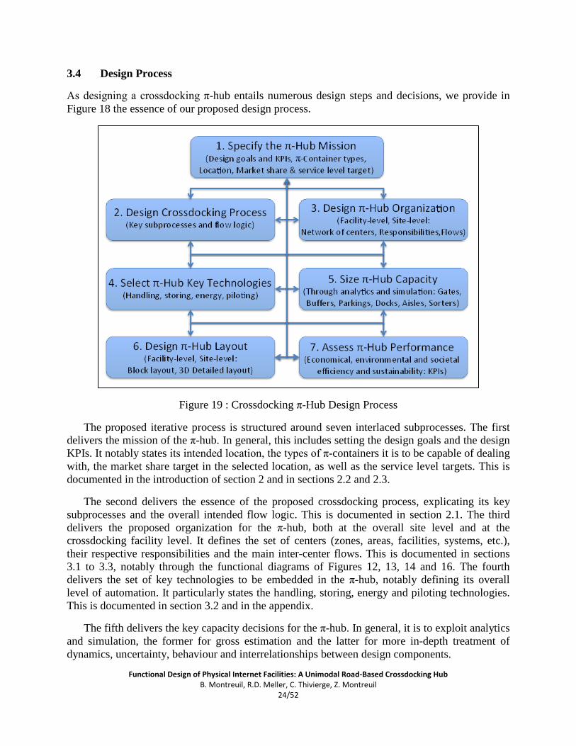
As designing a crossdocking π-hub entails numerous design steps and decisions, we provide in Figure 18 the essence of our proposed design process.
Figure 19 : Crossdocking π-Hub Design Process
The proposed iterative process is structured around seven interlaced subprocesses. The first delivers the mission of the π-hub. In general, this includes setting the design goals and the design KPIs. It notably states its intended location, the types of π-containers it is to be capable of dealing with, the market share target in the selected location, as well as the service level targets. This is documented in the introduction of section 2 and in sections 2.2 and 2.3.
The second delivers the essence of the proposed crossdocking process, explicating its key subprocesses and the overall intended flow logic. This is documented in section 2.1. The third delivers the proposed organization for the π-hub, both at the overall site level and at the crossdocking facility level. It defines the set of centers (zones, areas, facilities, systems, etc.), their respective responsibilities and the main inter-center flows. This is documented in sections 3.1 to 3.3, notably through the functional diagrams of Figures 12, 13, 14 and 16. The fourth delivers the set of key technologies to be embedded in the π-hub, notably defining its overall level of automation. It particularly states the handling, storing, energy and piloting technologies. This is documented in section 3.2 and in the appendix.
The fifth delivers the key capacity decisions for the π-hub. In general, it is to exploit analytics and simulation, the former for gross estimation and the latter for more in-depth treatment of dynamics, uncertainty, behaviour and interrelationships between design components.

Functional Design of Physical Internet Facilities: A Unimodal Road-Based Crossdocking Hub B. Montreuil, R.D. Meller, C. Thivierge, Z. Montreuil
25/52
In this paper, the use of analytics has been reduced to relying on simple ratios based on average times to approximately size the design elements (e.g., if trucks/trailers take 10 minutes on average at a gate, we would assume we would need one gate per four or five arrivals per hour). More refined analytical models, notably exploiting queuing network theory, are much needed and subject for further research. Exploiting the ratios to set design ranges, we have used a three-level simulation approach for capacity purposes:
1. Gateway: For approximately sizing the number of gateways, build and experiment with a level-one discrete-event simulation model rigorously representing dynamic demand yet assuming approximate black-box behaviour and capacity for the π-hub;
2. External site and Docking: For approximately sizing the number of π-docks, the dimensions of the external π-buffers, π-parkings and π-aisles, and adjusting the number of gateways, experiment with a level-two discrete-event simulation model built by extending simulation model 1 so as to rigorously represent the external layout and capacity of the site and the docking centers of the crossdocking facility, while assuming approximate black-box capacity for the preparation center of the crossdocking facility;
3. Global π-hub, including Preparation center: For sizing the preparation center and its components, as well as adjusting capacities for the rest of the π-hub, experiment with a level-three discrete-event simulation model built by extending simulation model 2 so as to rigorously represent the layout and behaviour of the preparation center.
At the three levels, simulation models have been built, validated and run using the Simio simulation platform [23]. Within each level, variants of the models have been developed appropriately for the considered design alternatives.
The sixth design subprocess delivers the π-hub layout at the site level and at the facility level, first an aggregate block layout and then a fine-granularity tridimensional detailed layout (here exploiting the SketchUp platform [24]). They are documented in section 3.2, 3.3 and 3.5 as well as in the appendix. The layouts have gradually elaborated in line with the three-level simulation approach used for capacity purposes. Indeed, the layouts have been used as inputs to the building the simulation models within the Simio platform, insuring integral direct correspondence between layouts and simulation models as well as allowing 3D animation for validation and demonstration purposes.
The seventh and final design subprocess delivers an assessment of the economic, environmental and societal efficiency and sustainability of the proposed design (see section 2.4). It exploits the key performance indices introduced in section 2.3. The results are documented in section 3.6.

Functional Design of Physical Internet Facilities: A Unimodal Road-Based Crossdocking Hub B. Montreuil, R.D. Meller, C. Thivierge, Z. Montreuil
26/52
3.5 Final Layout
We used the following data when determining the capacity and layout of the proposed π-hub:
1. Target throughput, excluding local trips to/from π-hub : Average of 10,000 truck-trailers/week Hourly truck-trailer throughput: Min 1.5, Average 59.4, Max 155.6 Hourly π-container throughput: Min 3, Average 268.4, Max 832 Overall throughput passing near location estimated using transport statistics data for
the Québec province of Canada and the Québec City region that provide distribution by blocks of 30 minutes for a typical week
2. Travel sources/destinations for a truck/trailer dealt with at the π-hub Seven directions as illustrated in Figure 10 Source/destination probability proportional to historically sampled flows recorded
through transport statistics data for the Québec province of Canada and the Québec City region
3. Driver behaviour estimation 70% want to return to the π-hub they came from 30% are open to pick a destination based on available requests for travel those in the 70% group are estimated to be willing to change their target destination
after a 30-minute waiting time without finding a shipment to carry to that target destination
4. Expediting to contain π-container waiting time π-Container is expedited after waiting 60 minutes to be assigned to a departing
truck/trailer, requesting a local truck/trailer for taking not yet dispatched π-containers waiting for its destination, this truck/trailer arrives within 15 to 20 minutes
5. Processing times InGate processing time:
o Normal Security: Exponential (0.5 minutes) o High Security: Exponential (1 minute)
Truck/trailer unloading time: 1 minute Truck/trailer loading time: Pert (2; 3; 4) minutes, including verification OutGate processing time:
o Normal Security: Exponential (0.5 minutes) o High Security: Exponential (1 minute)
Using the design process discussed earlier, we sized the facility’s capacity as follows: Number of InGates: 4 (2 sets of one normal security and one high security) Number of Buffer Spots for Truck-Trailers: 80 Number of π-docks: 30 Number of OutGates: 4 (one set of 2 normal security and 2 high security)

Functional Design of Physical Internet Facilities: A Unimodal Road-Based Crossdocking Hub B. Montreuil, R.D. Meller, C. Thivierge, Z. Montreuil
27/52
We now present our final layout from multiple perspectives, starting with an overview of the proposed site layout depicted in Figure 20. Colored arrows are overimposed on the layout to help visualize the key flow patterns.
Figure 20 : Overhead View of the Proposed Road-Based Crossdocking π-Hub Site Layout
Figure 21 : 3D Front View of the Proposed Road-Based Crossdocking π-Hub Site Layout

Functional Design of Physical Internet Facilities: A Unimodal Road-Based Crossdocking Hub B. Montreuil, R.D. Meller, C. Thivierge, Z. Montreuil
28/52
Figures 21 and 22 provide 3D views giving a sense of the site, respectively from the front and the back. Note the solar panels on top of the crossdocking facility, contributing energy to the π-hub. Also note the intense greenery helping with quality of air and noise pollution reduction.
Figure 22 : 3D Back View of the Proposed Road-Based Crossdocking π-Hub Site Layout
We provide Figures 23 and 24 to respectively highlight the high security gateways for inbound and outbound driver/truck/trailer/π-container traffic and the importance put on truck driver quality of life as exemplified by the driver service center implemented on site, which includes such amenities as restrooms, a food court and a small park.
Figure 23 : 3D View of the π-Hub Highlighting High-Security Gateways

Functional Design of Physical Internet Facilities: A Unimodal Road-Based Crossdocking Hub B. Montreuil, R.D. Meller, C. Thivierge, Z. Montreuil
29/52
Figure 24 : 3D View of the π-Hub Highlighting the Driver Service Center
Figure 25 : 3D View Overhead View of the Proposed Crossdocking π-Hub Facility Layout

Functional Design of Physical Internet Facilities: A Unimodal Road-Based Crossdocking Hub B. Montreuil, R.D. Meller, C. Thivierge, Z. Montreuil
30/52
Next we focus on the proposed layout for the crossdocking facility, with an elevation view and a bird-eye 3D view provided respectively in Figures 25 and 26.
Figure 26 : Bird-Eye 3D View of the Proposed Crossdocking π-Hub Facility Layout
Figure 27: 3D View Highlighting a Docking Center of the Proposed π-Hub Facility Layout

Functional Design of Physical Internet Facilities: A Unimodal Road-Based Crossdocking Hub B. Montreuil, R.D. Meller, C. Thivierge, Z. Montreuil
31/52
In line with the block layout of Figure 15, the central area of the crossdocking facility is occupied by the preparation center. Its π-buffers are depicted in dark gray. Each has direct access to and from the π-sorters, discriminated in terms of main intended direction of flow by the light gray and medium gray color-coding.
The docking centers are located on the left and right side of the facility. As highlighted in Figure 27, they implement the flow logic depicted in Figure 14. Notably, it clearly exhibits that trailers are to be backed into the facility to ease sideway loading and unloading.
Overall it depicts the ubiquitous usage of flexible conveyor technology (e.g. [21]) allowing four directions of movement with the conveying modules adapted to the standardized modular dimensions of the π-containers, indeed creating a highly flexible multidirectional conveying grid.
We provide ample further details on the final design in the Appendix to insure in-depth knowledge transfer.
3.6 Assessing the expected performance of the proposed design: the π-hub’s KPIs
Although the focus of this paper is not on how to determine the values of the KPIs, providing them for this conceptual design allows the reader to get a sense for how well the proposed π-hub is to be operating. The KPI values provided in Table 1 have been determined either directly from the capacity decisions and layout design, or via experimentation using a detailed discrete-event simulation model coded in Simio [23].
From a customer perspective offers breakthrough performance beyond current best practice with average throughput times in the π-hub on the order of 20 minutes. The open consolidation of flows enables all π-containers to be channelled during this throughput time to a truck/trailer aimed to their target destinations, with minimal expediting. Even with highly randomized content of arriving carriers in terms of sets of π-containers (dimensions and destinations), outgoing carriers are utilized at above 63% in average, much better than the about 50% industry standard practice. Such performance can still be improved significantly by improving synchronization and planning across the Mobility Web instead of taking a single π-hub point-of-view.
From an operator perspective, the π-hub is a highly potent and efficient beehive. It has a potential of 30 trucks/trailers to be docked for transhipment concurrently, with a simulated average and maximum of 12.7 and 30 respectively. It has the potential of concurrently processing up to nearly 5000 (1,2 x 2.4 x 2.4)-equivalent π-containers, with a simulated average and maximum of respectively 204 and 533 π-containers of various modular sizes processed concurrently,

Functional Design of Physical Internet Facilities: A Unimodal Road-Based Crossdocking Hub B. Montreuil, R.D. Meller, C. Thivierge, Z. Montreuil
32/52
Table 1. Performance Assessment for the Proposed π-Hub
KPI Value Customer
Throughput Time (minutes)
π-containers Average 21 Maximum 133
Trucks/Trailers/Drivers Average 22 Maximum 94
Time at π-dock (minutes) Trucks
Average 5.5 Maximum 13
Buffer waiting time (minutes) Trucks
Average 11 Maximum 80
Capacity utilization of departing carriers
Trailers Average 63,8%
Percentage departing in preferred direction
π-containers Average 100%
Trucks/Trailers/Drivers Average 97.3%
Percentage expedited assignments
π-containers Average 0.3% Trailers Average 1.7%
Operator
Area Site 134 000 m2
Facility 20 000 m2
Number of gates Inbound 2 + 2 = 4 Outbound 4
Number of docks 30
Number of gate queuing places Inbound 8 (2/gate)
Outbound 4 (1/gate)
Number of parking bays in the buffer 80
Number of π-containers (1.2 x 2.4 x 2.4 m) that can be processed concurrently within the hub facility 4858
Number of π-containers concurrently in the π-hub Average 204 Maximum 533
Number of docks concurrently used Average 13 Maximum 30
Number of positions used in the π-Buffer Average 11 Maximum 80

Functional Design of Physical Internet Facilities: A Unimodal Road-Based Crossdocking Hub B. Montreuil, R.D. Meller, C. Thivierge, Z. Montreuil
33/52
4 Conclusions and Future Research
As stated at the outset, the goal of this chapter was not to produce the optimal functional design of a unimodal road-based crossdocking π-hub. Rather, our primary goal was to produce a functional design that performed at an acceptable level in terms of user key performance indicators (KPIs). We also reported KPIs that a facility operator is likely to consider. Our secondary goal was to establish what details are needed to provide when one provides a functional design going forward.
Examination of our work will hopefully lead to future research on two fronts. First, we hope that functional designs of π-hubs that differ from the one presented here will be developed. As it is unlikely that one functional design will perform best over all possible ranges of input parameters, having a suite of functional designs to choose from will aid future facility operators. Notable research avenues include the assessment of alternative handling technologies and alternative levels of automation on π-hub functional design and performance, as well as the investigation of functional design of crossdocking π-hubs for alternative sets of allowed π-containers. Examples include removing the 2,4m by 2,4m slice dimensional constraint to allow any π-container with modular dimensions of 1,2m or 2,4m wide and high, and crossdocking π-containers with much smaller dimensions, such as the series 0,12m, 0,24m, 0,36m, 0,48m, 0,6m and 1,2m along the three dimensions.
Second, we used simulation as a means to assess capacity requirements and evaluate our designs. We believe this is the most appropriate method for establishing the performance of the facility. However, simulation is currently a cumbersome process when also used, as we did, to iteratively design a facility and sequentially choose the appropriate levels of resources. Research is thus needed on two fronts. On one front, investigate how to exploit the standardized modularization of the Physical Internet to enable the creation of efficient simulation-supported logistics facilities and site design such as π-hubs. On the other front, develop analytical models that could be helpful in terms of evaluating the performance and capacity requirements of sub-systems of the π-hub, using for example queuing network theory such as was initiated for π-transit design [**].
Third is the design process itself. We introduced an iterative π-hub design process that represent the essence of our empirical learning-by-doing through the research project on which is based this chapter. We do not consider this proposed process as the ultimate one. For example, our three-level simulation-based capacity assessment subprocess may surely be improved through further experimental and instrumental research. Overall, research on improving the π-hub design process may not only reduce and streamline the design realization efforts, but also improve the designs that result.

Functional Design of Physical Internet Facilities: A Unimodal Road-Based Crossdocking Hub B. Montreuil, R.D. Meller, C. Thivierge, Z. Montreuil
34/52
Acknowledgements
This work was supported in part by the Material Handling Industry of America (MHIA), by the Canada Research Chair in Enterprise Engineering and by the Discovery Grant Program of the Natural Science and Engineering Research Council of Canada. Any opinions, findings, and conclusions or recommendations expressed in this material are those of the authors and do not necessarily reflect the views of the supporting organizations.
References
[1] Montreuil, B., “Toward a Physical Internet: Meeting the Global Logistics Sustainability Grand Challenge”, Logistics Research, 3(2-3), 71-87 (2011).
[2] Montreuil, B., “The Physical Internet Manifesto”, www.physicalinternetinitiative.org, version 1.0 2009-09-14, version 1.10 accessed on 2012-07-16.
[3] Montreuil B., R.D. Meller & E. Ballot. “Physical Internet Foundations”, in Proceedings of INCOM 2012 Symposium, Bucharest, Romania, May 23-25 (2012).
[4] Montreuil, B., “The Physical Internet,” Roundtable Discussion, 2010 International Material Handling Research Colloquium, Milwaukee (WI; USA), June (2010).
[5] Montreuil, B., Meller, R.D., and Ballot, E., “Towards a Physical Internet: The Impact on Logistics Facilities and Material Handling Systems Design and Innovation,” in Progress in Material Handling Research: 2010, Material Handling Institute, Charlotte, NC, 305-327 (2010).
[6] Meller, R. D. and Montreuil, B, “Designing Material Handling Systems and Facilities for the Physical Internet,” Material Handling Industry of America (July 2010 – July 2012).
[7] Meller, R.D., B. Montreuil, C. Thivierge & Z. Montreuil, “Functional Design of Physical Internet Facilities: A Road-Based Transit Center”, Progress in Material Handling Research: 2012, Material Handling Institute, Charlotte, NC, USA (2012).
[8] Ballot, E., Montreuil, B., and Thivierge, C., “Functional Design of Physical Internet Facilities: A Road-Rail hub,” Progress in Material Handling Research: 2012, Material Handling Institute, Charlotte, NC, USA (2012).
[9] Ballot, E., Montreuil, B. and Glardon, R., “Simulation of the Physical Internet in the Context of Fast-Moving Consumer Goods Sector in France,” PREDIT, France (2011/01 –2012/06).
[10] Meller, R. D. and Ellis, K. P., “An Investigation into the Physical Internet: Establishing the Logistics System Gain Potential,” in Proceedings of the International Conference on Industrial Engineering and Systems Management, Metz - France, 575-584 (2011).
[11] Meller, R. D. and Ellis, K.P., “Establishing the Logistics System Gain Potential of the Physical Internet,” U.S. National Science Foundation and Physical Internet Thought Leaders (2010/06 –2012/06).
[12] Meller, R. D., Lin, Y.-H., and Ellis, K. P., “The Impact of Standardized Metric Physical Internet Containers on the Shipping Volume of Manufacturers,” in Proceedings of the 14th IFAC Symposium on Information Control Problems in Manufacturing, Bucharest – Romania, (2012).
[13] Gue K.R., “Effects of trailer scheduling on the layout of freight terminals”, Transportation Science, 33(4), 419-428 (1999).
[14] Bartholdi J.J. & K.R. Gue, “The Best Shape for a Crossdock”, Transportation Science, 38(2), 235-244 (2004).

Functional Design of Physical Internet Facilities: A Unimodal Road-Based Crossdocking Hub B. Montreuil, R.D. Meller, C. Thivierge, Z. Montreuil
35/52
[15] Gümüs M. & J.H. Bookbinder, “Cross-Docking and its implications in location-distribution systems”, Journal of Business Logistics, 25(2), 199-228 (2004).
[16] Bozer Y.A. & H.J. Carlo, “Optimizing inbound and outbound door assignments in less-than-truckload crossdocks”, IIE Transactions, 40, 1007-1018 (2008).
[17] Kim C., K.H. Yang & J. Kim, “A Strategy for third-party logistics systems: A case analysis using the blue ocean strategy”, Omega, 36, 522-534 (2008).
[18] Ross A. & V. Jayaraman, “An evaluation of new heuristics for the location of cross-docks distribution centers in supply chain network design”, Computers & Industrial Engineering, 55, 64-79 (2008).
[19] Boysen N. & M. Fliedner, “Cross dock scheduling: Classification, literature review and research agenda”, Omega, 38(6), 413-422 (2010).
[20] Vis I.F.A. & K.J. Roodbergen, “Positioning of goods in a cross-docking environment”, Computers & Industrial Engineering, 54, 677-689 (2008).
[21] Furmans K., F. Schönung, & K.R. Gue, “Plug-and-Work Material Handling Systems”, Progress and Research in Material Handling: 2010, Material Handling Institute, Charlotte, NC, USA (2010).
[22] Montreuil B., J. Ashayeri, J. Lagerwaard & G. Janssen, “Business intelligence design for live piloting of order fulfillment centers”, Progress in Material handling Research: 2008, Material Handling Industry of America, 417-445 (2008).
[23] Kelton, W. D., Smith, J. S., Sturrock, D.T., Simio and Simulation: Modeling, Analysis, Applications (software version: 4.62.7799), McGraw Hill, (2012).
[24] Trimble, SketchUp home page, http://www.sketchup.com/intl/en/index.html, accessed 2012/08/14 (2012).

Functional Design of Physical Internet Facilities: A Unimodal Road-Based Crossdocking Hub B. Montreuil, R.D. Meller, C. Thivierge, Z. Montreuil
36/52
Appendix This appendix provides further details on the functional design of a unimodal road-based crossdocking π-hub. It is structured as a complementary add-on, assuming the reader has previously read the core of the paper. The appendix focuses on specific facets: (1) flow patterns across the π-hub site through examination of key scenarios, (2) flow patterns in a π-dock, and (3) key equipment and technologies of the π-hub.
A.1 Flow patterns across the π-hub site: a scenario based description
First let us recall that the π-hub site is designed with two symmetric sides having nearly identical yet inverted flows.
From a flow pattern perspective, there are facets of the design that can be generically described while others are better described through explicit scenarios. We start here by the generic facets, then the following sections cover the scenario based facets.
Generically, trucks that want to enter in the π-hub site might come from various π-nodes of the Physical Internet enabled Mobility Web. They can have access to the π-hub site from the road adjacent to the π-hub on its front side (node 1, as labeled in Figure 17).
Prior to getting to the π-hub, the driver has answered to the π-system procedure’s questions by a simple click with is truck’s multidisciplinary dashboard computer. Some questions are related to the driver status and needs. By example, does the driver need or want to go to the π-Service in order to relax, eat in the food court, go to the bathroom, stretch his legs, or simply rest? Other questions are about validating from where it comes and where is its intended next destination(s). The π-system has also already hooked automatically to the truck’s onboard computer and gotten the log of all loaded π-containers and their pertinent logistics information. The π-system has also communicated with its equivalent at the source π-hub form where the truck comes from, and gotten the equivalent information for cross validation and advanced scheduling purposes.
When the truck is quite near the π-hub, the π-system communicates to the driver the specific π-InGate he has to pass through to enter the π-hub. The truck enters into the site by the dispatched π-InGate (node 3 or 4) and all the on-site identification and scanning processes begin. After this, the π-system analyzes its database to give an efficient work order to the driver, according to the π-hub site and facility status and flow velocity. A detailed path and task description is shown on the truck’s computer. The driver has to clearly understand and report his acceptance of his work order from his truck’s computer. Then, when he presses the confirmation button on the truck’s multidisciplinary dashboard computer, an access barrier rises and lets him enter in the π-hub by the appropriate π-aisle (node 10 or 14).
Then, three scenarios might happen. The scenarios are sorted by their importance in term of flow quantity, the first two scenarios happening regularly while the third one happens rarely.

Functional Design of Physical Internet Facilities: A Unimodal Road-Based Crossdocking Hub B. Montreuil, R.D. Meller, C. Thivierge, Z. Montreuil
37/52
A.1.1 Scenario 1
The first scenario is one of the two most common ones of the π-hub site. It is clearly the most efficient one. It corresponds to the case when a truck or truck-trailer enters the π-hub site, goes directly to the π-hub’s crossdocking facility, tranships some π-containers and leaves the π-hub site. Figure A1 illustrates intuitively this scenario and its two main paths. In addition, exploiting the color-coding of Table A1, the flow network in figure A2 provides another interesting perspective over this scenario.
Figure A1: π-Hub Site Flow: Scenario 1

Functional Design of Physical Internet Facilities: A Unimodal Road-Based Crossdocking Hub B. Montreuil, R.D. Meller, C. Thivierge, Z. Montreuil
38/52
Table A1: Flow Node Scenario 1
Figure A2: π-hub conceptual flow network: scenario 1
In scenario 1, the truck carrying its trailer comes from the road (node 1). Normally the π-
system has already analyzed the transported π-containers on the truck/trailer so as to assign correctly the truck to a specific π-InGate for efficiency purposes. Then it enters by one of the two π-InGates (nodes 2 or 4), each leading to a distinct path starting with either π-aisle (node 10) or π-aisle (node 14). Then the truck engages in the π-maneuver (node 11 or 13) to reach the side of the π-hub facility (node 12) to which it has been dispatched. On the proper π-maneuver, the truck does some positioning moves and goes slowly backward in its assigned π-dock (node 12). In addition, while the driver moves back to enter in his assigned π-dock, he is assisted by the truck’s multidisciplinary dashboard computer to increase the operation speed, reduce the risk of breakage and synchronize the movement of his truck with others around. When the truck is correctly set in the right π-dock, the π-system initiates the partial or full transfer of π-containers from the truck’s composed trailer to the π-hub facility.
Simultaneously, the π-hub facility aims to transfer some previously prepared π-containers on the truck’s trailer that have the same intended next destination as the truck. This operation is aimed to be very quick and efficient; the truck is notably not allowed to stay in its dispatched π-dock for longer than its transferring time. If there is no loading π-containers ready, there will only be the unloading process and the truck will move out of the π-crossdock to avoid any kind of deadlock, in line with scenario 3. So, the truck can stay in the π-crossdock only if he is loading or unloading, otherwise, he has to leave and give the possibility to other truck/trailer to use the π-dock.

Functional Design of Physical Internet Facilities: A Unimodal Road-Based Crossdocking Hub B. Montreuil, R.D. Meller, C. Thivierge, Z. Montreuil
39/52
After the transhipment process is complete, the truck has to reach the exit of the π-hub site to depart toward its intended destination. Depending on which side of the building (node 12) the truck is, it moves forward into the π-maneuver (node 11 or 13), turns on the π-aisles (node 10 or 14), turns on the π-aisles (node 20 or 21), passes under the security and identification check of the π-outgate (node 26) and reaches the exit road (node 27) to get going with its delivery.
A.1.2 Scenario 2
The second scenario is the next most common one in the π-hub site. It corresponds to the case when a truck carrying a π-trailer (or not) enters the π-hub, unloads some π-containers in the π-hub Facility, then goes in the π-Parking to wait for the readiness of its assigned load of π-containers, allowing the driver to walk to the π-Service and then come back to his truck at the right time. After a great relaxing moment in the π-Service, the driver moves its truck/trailer to the π-hub crossdocking facility, loads some π-containers and leaves the π-hub. Using the color-coding of Table A2, Figure A3 illustrates intuitively this scenario and its two main paths. In addition, the flow network in Figure A4 gives another interesting perspective on this scenario.
Table A2: Flow Node Scenario 2
The flow of a truck according to scenario 2 is identical to that of scenario 1 until it reaches its assigned π-dock of the π-hub facility (node 12). The main difference starts with the fact that in scenario 1 the set of π-containers to be loaded on the truck/trailer is available and the loading is performed while the truck is docked, while in scenario 2 this set is not yet available so that the driver has to move his truck away from the π-dock and wait for a readiness signal before coming back to the π-dock.
Depending on which side of the building (node 12) the truck is, it moves forward into the π-maneuver (node 11 or 13) and turns on the π-aisles (node 10 or 14). After this, the driver gets on the path that will lead him in the π-buffer and, if he wants to, in the π-service. So, the truck turns on the π-aisle (node 19 or 22), turns again on the π-aisle (node 6 or 18), moves in the π-maneuver (node 7 or 17) and enters in the π-buffer (node 8 or 16). Then, the driver parks his truck in this area, if he wants and has the time, he will walk to the π-Service (node 5) to relax. A person might want to go in the π-Service (node 5) because it is a social place where people can talk together, or relax a little bit of time before doing another ride, or eat something at the food court, or go to the bathroom, or simply spend some time on a bench, etc.

Functional Design of Physical Internet Facilities: A Unimodal Road-Based Crossdocking Hub B. Montreuil, R.D. Meller, C. Thivierge, Z. Montreuil
40/52
Figure A3: π-Hub Site Flow: Scenario 2
Figure A4: π-Hub Site Conceptual Flow Network: Scenario 2

Functional Design of Physical Internet Facilities: A Unimodal Road-Based Crossdocking Hub B. Montreuil, R.D. Meller, C. Thivierge, Z. Montreuil
41/52
The time allocated to the driver in this area is predetermined in a timetable in the π-system in order to synchronize, manage and optimise the operations within the π-hub site. When the driver has not a lot of time left, he walks back to his truck and wait for the signal of the π-system on his truck’s computer to continue his work order. At this point, the truck might lead back in the π-hub facility (node 12) or goes directly to the π-outgate (node 10). In the first possibility, the truck moves forward in the π-maneuver (node 9 or 15), passes on the π-aisle (node 10 or 14), makes some moves on the π-maneuver (node 11 or 13) and moves backward in the π-hub facility (node 12). Then, some π-containers are loaded and the truck leaves the π-dock and moves forward in the π-maneuver (node 11 or 13) to enter on the π-aisle (node 10 or 14). After that, it turns on the π-aisles (node 20 or 21), passes through security and identification check of the π-outgate (node 26) and reaches the road (node 27) to complete its delivery job. In the second possibility, the truck moves forward in the π-maneuver (node 9 or 15), passes on the π-aisle (node 10 or 14) only and reaches the exit the same way as said earlier.
A.1.3 Scenario 3
The third scenario is aimed to occur rarely in the π-hub. It corresponds to the case when a truck (node 12) docked on one side of the π-crossdock has to move on the other side of the building. For example, it occurs when a truck waiting in the π-buffer on the left side of the building is dispatched to move on the right side to pick up other goods. The truck will also pass by a π-Buffer (node 8 or 16) and the driver could also walk to the π-Service (node 5). It is rarely supposed to happen because in general it is more efficient and profitable to move the π-containers inside the π-crossdock (node 12) instead of moving a truck around the facility in the site. Figure A5 illustrates intuitively this scenario and its two main paths. Based on the color-coding of Table A3, the flow network in Figure A6 gives another interesting perspective over this scenario. Based on these Figures, the flow pattern for this scenario can be made explicit by the reader as was done for the second scenario.
Table A3: Flow node scenario 3

Functional Design of Physical Internet Facilities: A Unimodal Road-Based Crossdocking Hub B. Montreuil, R.D. Meller, C. Thivierge, Z. Montreuil
42/52
Figure A5: π-hub flow: scenario 3
Figure A6: π-hub conceptual flow network: scenario 3

Functional Design of Physical Internet Facilities: A Unimodal Road-Based Crossdocking Hub B. Montreuil, R.D. Meller, C. Thivierge, Z. Montreuil
43/52
A.2 Flow patterns in a π-dock
In this section we develop furthermore the flow patterns in a π-dock. Figure 27 highlights some π-docks amongst the fifteen proposed within one of the two docking centers. Figure A7 conceptually depicts the flow logic for a π-dock The truck/trailer docking bay is the exact location where the truck moves backward to stay into the π-hub Facility. The truck stays there during all the π-containers unloading and loading processes and exits afterward. The π-container unloading buffers are dedicated to the incoming π-containers and have to be clear most of the time to receive new π-containers. The π-containers stay composed together in the unloading buffer 1 but they might be detached in the unloading buffer 2. In addition, the π-container loading buffers are where full or partial blocks of composed π-containers are waiting to be loaded on the next trucks/trailers coming in.
Figure A7: Developed close up of the π-dock
There are nine flow scenarios that can happen between the six sub-areas of the π-dock of the π-hub facility:
1. The first flow happens every time a truck has to unload some π-containers in the π-hub Facility. It is the transfer of π-containers from the truck/trailer docking bay to the unloading buffer 1. To do so, the trailer detached all the π-containers from its platform to able them to move in any direction. Then, only the π-containers that do not go in the same intended destination as the truck move into the unloading buffer 1. Depending on the location of every π-container on the trailer, it is possible that the trailer has a multiple empty areas instead of only one. In that case, all the π-containers that stay on the trailer will move on the trailer in compact groups aimed for the same unloading destination. This operation offers the possibility to put bigger π-containers on the trailer by reducing the trailer’s container configuration constraint. Normally, while unloading and reconfiguration is completed, another set of π-containers waits to be load on the truck/trailer. The unloading and loading processes can be done in synchronous fashion.
2. The second flow happens when a truck had left π-containers in the unloading buffer 1. These have to move directly to the unloading buffer 2. to reach the preparation center of the π-crossdock facility or a loading buffer of the current π-dock. The movement of π-containers has to be quick because the unloading buffer 1 has to be kept clear for minimizing unloading blockage when receiving new π-containers to unload.

Functional Design of Physical Internet Facilities: A Unimodal Road-Based Crossdocking Hub B. Montreuil, R.D. Meller, C. Thivierge, Z. Montreuil
44/52
3. The third flow happens when π-containers of the unloading buffer 2 are needed in the preparation center or other π-docks which are not directly adjacent to buffer 2. In brief, the unloading buffer 2 transfers π-containers to the π-sorter. The π-sorter has priority of movement over the unloading buffer 2. That means the π-containers that want to move into the π-sorter have to wait until it is clear to move forward. The π-sorter is multidirectional but mainly moves in to the prescribed direction to facilitate the movement and to ease handling of the biggest size of π-container.
4. The fourth flow happens when π-containers in the unloading buffer 2 move in the loading buffer 1 to be later loaded on the second next truck/trailer at the same π-dock. The movement of π-containers has to be quick because the unloading buffer 2 has to stay clear for receiving new π-containers with no blockage. When transferring into loading buffer 1, reach others that have the same intended destination and get composed with them.
5. The fifth flow happens when the π-containers traveling through the π-sorter reach the right π-dock and enter in loading buffer 1.
6. The sixth flow happens when a set of (composite) π-containers is ready to move from loading buffer 1 to loading buffer 2 to be eventually moved on the loading buffer 3 to be shipped.
7. The seventh flow happens when π-containers coming from the π-sorter reach loading buffer 2 to finish or increase the length of a block of π-containers that will be shipped. Normally, it is aimed to compose earlier all π-containers that will be shipped to minimize handling, yet tight timing may require bypassing this intent.
8. The eight flow happens when a π-containers move from loading buffer 2 to loading buffer 3. If the level of activity is low, we can have only a few independent π-containers that want to reach loading buffer 3 to be shipped. But when the level of activity is high, it will be more composed blocks of π-containers that will be moved to the loading π- buffer 3.
9. The ninth flow happens every time a truck/trailer has to take some π-containers from the π-crossdock and loading them onto its platform. Once the (composite) π-containers are moved onto the platform, they are interlocked with those adjacent that have the same unloading destination. They also fix themselves to the platform. The truck waits for the π-system approbation to undock and then moves forward to the exit of the π-hub. When the truck is no more in the π-dock, another truck can go in and launch the same transferring process.
A.3 Key equipment and technologies of the π-hub
We provide here information about key innovative technologies and equipment requirements in order to have a functional and efficient π-hub. Such technologies and equipment are spread to a lot of facilities in the Physical Internet.
π-system
The necessities of development for the Physical Internet π-system are abundant regarding the information technology. Here, we deal only with features that relate to the π-hub and its users. The π-system collects and coordinates all operations of the π-hub and constantly updates its databases. In fact, all equipment in the proposed π-hub are automated and controlled in a distributed way exploiting digital interconnectivity across networked controllers and computers.

Functional Design of Physical Internet Facilities: A Unimodal Road-Based Crossdocking Hub B. Montreuil, R.D. Meller, C. Thivierge, Z. Montreuil
45/52
The π-system uses the Digital Internet, so that all Digital Internet users may consult the Physical Internet databases in real time. Illustratively, the π-system can track the movements and status of all trucks, trailers, equipment and π-facilities of the Physical Internet, for example through the exchange of data with the truck’s wireless multidisciplinary dashboard computer, explained later on.
In short, the π-system enables the management and synchronization of the operations of the various equipment in the π-hub, such as validation gates, barriers, truck’s multidisciplinary dashboard computers and x-ray inspection and radiation detection systems. It is also the platform that transmits electronically to the truck computers the work orders and manages all the π-containers exchange processes of the π-hub.
The tasks below have to be done through the π-system in order to have a functional and effective π-hub. There are elements to manage before a truck entered the π-hub, while a truck is in the π-hub and after a truck has exited the π-hub.
Before a truck entered the π-hub
• It has to ask the driver, in a reasonable time in advance for planning purposes, if he wants to have a little break and go in the π-Service.
• It has to collect when applicable the results of previous x-ray scans of the truck/trailer, in order to compare it to the one that will be done at the π-ingate of the π-hub later on. Also, it has to know which kind of verification it will have to do to the truck and it composed trailer.
• It has to constantly update its database of the incoming trucks and the π-containers they carry in order to manage efficiently the future exchange of goods inside the π-hub.
• It has to organise and plan the exchange of π-containers matches of the π-hub from one carrier to another.
While a truck is in the π-hub
• It has to constantly optimize the allocation of trucks to the π-ingates, the π-outgates, the π-buffers and the π-docks.
• It has to manage the flow of trucks, aiming to avoid deadlocks and generally minimize traffic through its work orders (notably π-dock assignment).
• It has to orchestrate movement of the π-containers inside the π-crossdock and always update the database in order to improve the matching decisions. The goal is to reduce the total travelled distance and trafic congestion.
• It has to analyse the driver moves and give advices in some critical zone through the truck’s multidisciplinary computer.
After a truck exited the π-hub
• It has to update its database and communicate any relevant information to the next π-node in the path of the truck having departed.

Functional Design of Physical Internet Facilities: A Unimodal Road-Based Crossdocking Hub B. Montreuil, R.D. Meller, C. Thivierge, Z. Montreuil
46/52
Truck’s multidisciplinary dashboard computer
Truck multidisciplinary computers (see Figure A8) are usually
located in the dashboard of the truck and are used as a communication interface between the driver and the π-system.
This computer is fit to deal daequately with the standards and protocols of the Physical Internet. Each computer will continuously be communicating with the π-system (e.g. through a network of satellites that will provide wireless Internet access). Furthermore, the connected computer will be
used as a GPS and offer several solutions to reach the desired destination depending on the chosen goal. For example, the driver may want to arrive at a destination as soon as possible, or use less energy to arrive at his destination or simply use the path that provides the minimum distance to reach the destination. Also, the computer can determine the best interconnected paths to avoid traffic areas, construction zones and other possible causes of delay by using the Physical Internet real time database or historical statistics. In addition, the it will receive work orders corresponding to the transport needs of trailers across the network and within π-Facility. For example, for the π-hub, the computer will show explicitly the operations that the driver will undertake within the various areas of the π-Facility. In addition, the driver can use the Digital Internet in order to have a constant access to his mailbox, to find restaurants and gas stations quickly and keep informed of the news that can affect his job. Also, supervisors will be able to send personal communications to the driver, urgent advices and training documentaries through this interface. This computer has a function to calculate the number of hours of driving that the driver makes in a day to make sure that the standards of maximum daily hours of work are respected in the assignment of work orders. The truck’s multidisciplinary dashboard computer gathers the information below:
• Its unique identification number ; • The unique identification number of the current driver of the truck; • The unique identification number of the trailer attached to the truck; • The unique identification number of every π-container it carries; • The serial number of the truck; • The registration number of the truck; • The insurance number related to the truck; • The last thorough check of the truck and the dates for future checkups; • The identification number of the attendant in charge of the computer; • GPS positioning; • An interactive and detailed map of all π-nodes to visit; • The historic list of the π-nodes visited and planned to be visited; • The number of driving hours remaining in the day for the driver in the truck; • The work order history and planning; • Important documents and messages to drivers.
In addition, the multidisciplinary computer will update the database for each status change in real time together with the π-system and the validation wireless RFID gates.
Figure A8: truck’s Computer

Functional Design of Physical Internet Facilities: A Unimodal Road-Based Crossdocking Hub B. Montreuil, R.D. Meller, C. Thivierge, Z. Montreuil
47/52
In this manner, it will be possible to know with exactitude and for any time: the location, the π-containers, the driver, the planned path and equipment used for a truck while it is in function. Also, this tool will help the driver to move easily by showing on the screen is movement closely while he tries to move into a targeted π-node.
Wireless data exchange system
The wireless data exchange system significantly reduces the number of wires for the proper functioning of the π-hub. In fact, a lot of automated equipment in the π-hub need to share data with the π-system using a wireless data exchange network. The network has to be secure so that hackers cannot manipulate or modify information transmitted with the π-system. Otherwise, intruders could control the π-hub, have access to confidential information and sabotage the π-system or the π-hub and its equipment. In brief, coding information traded is essential for legal and safety concerns. Antennas have to be placed at different strategic locations in the π-hub in order to have a complete wireless coverage over the π-hub.
Smart tag identification for road based trailer
Smart tags are used to gather information about their owner. They are reusable, rewritable, standardized, encrypted and regulated chips by the Physical Internet organization. These smart tags are used to collect and update information on the trailer and the π-containers it carries. They are simply located inside a metal part of the trailer, specifically at the end of the trailer to ease the card reader operation in the design by radio frequency. They mainly contain the following type of information:
Information on the trailer
• The unique trailer’s identification number; • The registration number of the trailer; • The identification number of the agent in charge of the logistics equipment; • The last full and thorough equipment status audit; • The serial number of the equipment; • Specific dimensions and features of the equipment; • Historic movement of the equipment for better traceability;
Information on the carried π-containers
• The unique identification number of all π-containers carried; • The full list of delivery items inside all the π-containers; • The precise location of goods inside all the π-containers; • Maintenance information and particular terms of the commodities; • The unique identification number of the owner (s) of the commodities; • The exact addresses of final destination and origin of all the π-containers; • The expected entire path of each π-container; • Historic movement of the π-containers for better traceability.

Functional Design of Physical Internet Facilities: A Unimodal Road-Based Crossdocking Hub B. Montreuil, R.D. Meller, C. Thivierge, Z. Montreuil
48/52
All these information are needed to feed the π-system database in order to have better control and management over the Physical Internet equipment and processes. This smart tag technology is to be used in order to have accurate tracking of goods carried, to increase the security of the goods and the speed advisory information on the trailer and the π-containers. It is essential to update this information when there is a change of status because it is with this data that the π-system makes its operational decisions. So, traceability of equipment is no longer difficult because of this procedure. Also, in case of transit reprieve, it will be possible to inform the various people concerned and involved that there is a schedule delay. The final recipients, other intermediaries and carriers and intermediate π-Facilities can be made aware of the changes.
Smart card identification for drivers
Smart cards are use to identify drivers and they are reusable, rewritable, standardized, encrypted and regulated chips certified for Physical Internet usage. These smart cards are used to collect and update information about the driver and the equipment he uses and use a radio frequency technology. It contains mainly the following information:
Information on the driver
• The unique identification number of the driver; • The unique identification number of his truck; • Full name and date of birth; • Complete primary residence address; • Cellular phone number; • A picture; • Insurance policy number; • Licence number and class of driver; • Passport number; • Health problems and medications ordered; • The unique identification number of the truck currently driven; • The unique identification number of the agent in charge of him in term of logistics; • The complete list of different π-nodes that he is familiar with; • Some virtual money for purchase in π-nodes.
The card gathers all information in one facilitator document which greatly improves the speed of identification of drivers while having a formal proof that the driver is officially certified for the Physical Internet. This PI certification allows a better control on the driverflow in, across and out of the π-hub. Also, this card provides easy access to accurate information about its owner without having to consult the Physical Internet database, it is more direct. This document must be constantly updated in case of status change or reference numbers.

Functional Design of Physical Internet Facilities: A Unimodal Road-Based Crossdocking Hub B. Montreuil, R.D. Meller, C. Thivierge, Z. Montreuil
49/52
X-ray and radiation detection inspection system
The required security levels of logistics facilities are steadily increasing due to acts of abuse and smuggling. International Trade and the SAFE framework of standards aim to secure and facilitate the international supply chain that requires major reforms regarding several aspects of international trade1. For example, take the decision of the United States to require 100% inspection of containers shipped from foreign ports. To implement a system capable of detecting fraud quickly is an important concept that π-hubs needs to have. This is why X-ray inspection systems (see Figure A9) will be located in the deep-inspection π-ingates and π-outgates. More specifically, the method consists in recording slice by slice an X-ray scan that passes through the vehicle, its trailer and its π-containers. Then a computer system assembles the information and produces a high-resolution color image of the vehicle. The inspection system will provide this information to the π-system database via the wireless network. The π-system will receive the three-dimensional color image of a container, a trailer or a truck. If this is the first time that the equipment is inspected, a π-hub employee trained for this purpose, will inspect the image carefully and validate its legality. After this is done, the three-dimensional image is recorded and transmitted to the π-system database for possible comparisons of three-dimensional images for future inspections. Regarding the second and subsequent inspection of the same equipment, the π-system compares only the three-dimensional image with the newly created archived image if a second inspection is done. If the images are identical, the equipment is still considered compliant and legal.
Primarily, the x-ray security system will check the conformity of the goods and detect illegal shipments as drugs and weapons. In addition, it is possible to guard against certain radioactive materials by using a radiation detection portal that will also provide its analysis to the π-system. Some companies and governments require this security level and compliance audit. This kind of inspection system is already available in France and provides a comprehensive and automated analysis in less than 14 seconds2. With this analysis processing speed, the economic and operational activities will not be penalized.
Wireless RFID gates
Authentication doors and gates can read and write information on smart cards. They use radio frequency technology to ensure the proper functioning and security of the π-hub. They are used to catch information on trucks, trailers and π-containers at several locations within the π-hub. In fact, they collect or provide information of the smart card identification for driver, the smart tag identification for the road based trailer and the truck’s multidisciplinary dashboard computer. This means of communication and validation is essential to properly track the movement of trucks and π-containers within the π-hub.
1 www.wcoomd.org, Organisation mondiale des douanes, Actualité numéro 55, février 2008 2 http://www.varmatin.com/article/var/douanes-un-scanner-mobile-pour-detecter-les-fraudes
Figure A9: X-ray system

Functional Design of Physical Internet Facilities: A Unimodal Road-Based Crossdocking Hub B. Montreuil, R.D. Meller, C. Thivierge, Z. Montreuil
50/52
It is by these recognition doors and gates that the wireless network of transmission of information may provide data to the π-system to allow or disallow certain paths, access or actions in the π-hub. In short, the authentication doors and gates are the major collectors and transmitters of information in the π-hub.
Authorization lever arm access barrier
The authorization lever arm access barriers grant access to certain authorized vehicles to several areas of the π-hub. This equipment is used to control the movement of vehicles in the π-hub. Barriers are all connected to a validation wireless RFID gate that exchanges data with the π-system via the wireless network. An authorization lever arm access barriers will rise for a vehicle only if the computer truck’s multidisciplinary dashboard computer has been granted permission to access a particular area or if the level of traffic is low and allow it. In fact, these validation gates read the truck’s computer password and allow the vehicle to access another area of the π-hub. We can find this kind of barriers in the π-ingates and π-outgates.
π-InGate and π-outgate
The π-ingates and the π-outgates firstly receive and collect information about each entity trying to enter or exit the π-hub. A combination of validation wireless RFID gates, authorization lever arm access barriers and x-ray and radiation detection inspection system gather a lot of information concerning the truck, its driver and the π-containers it carries and send them to the π-system for a check up or to update the database. This security and identification process is required for any entities that want to come in or go out the π-hub. Normally, the π-system has defined previously choose where the entity has to go in which π-gate bay number. Depending on the request of the π-system or on the transportation needs, the truck will pass under a rapid or deep security scan. If the entity is going through the deep scan, all its’ equipment is inspected by an x-ray and a radiation detection system to identify illegal merchandises or dangerous goods. This inspection is automatic and is done with both the π-system and a security agent of the management office. A special procedure is engaged if something is considered or unusual. The rapid security gates circumvent this procedure for vehicles and composed trailers, but both kinds of security gates will read or update information on the driver identification smart card and the trailer smart card. The information taken from the vehicles is compared with those of the π-system database. If everything matches, the π-system will transfer a prior made work order to the truck’s multidisciplinary dashboard computer. If something is wrong, a special procedure is starting. At the same time, all the authorizations needed to move into the π-hub are sent to this computer. The work order can be adjusted depending on contingencies, needs and capacities of the π-hub. Each work order is obtained by different algorithms from the π-system in order to reduce traffic, time wasted and total distance. This work order shows every π-aisle that have to be taken and every location which has to be reached so the job can be correctly completes inside the π-hub, in a specific time frame. When the driver has manually confirmed that he has understood and received the work order and all the authorizations he needs for the π-hub, a barrier rises and lets him enter the π-hub. The same procedure is made when a truck passes through the π-outgate, but less request are send to the π-system.

Functional Design of Physical Internet Facilities: A Unimodal Road-Based Crossdocking Hub B. Montreuil, R.D. Meller, C. Thivierge, Z. Montreuil
51/52
π-conveyor
π-conveyor s used in π-crossdock are designed and engineered to exploit the characteristics of π-containers and to provide adequate efficiency and flexibility. As depicted in Figure A10, recently introduced flexconveyors [21] are representative of the type of conveying technology used in the π-hub. These plug-and-play modular conveyors allow moving things in the four cardinal directions. The π-crossdock will use π-conveyors to manage, move and keep temporarily π-containers within the π-hub Facility. When combined with others, a π-conveyor becomes a piece a flexible multidirectional transportation grid for π-containers (see Figure A11). All π-conveyors have a single dimension of 1.2 meter of length by 1.2 meter large in order to move the smallest π-container unit of the π-hub. The synchronized utilization of ten π-conveyor s simultaneously allows carrying the biggest π-container of the π-hub (12-meter long). We use this technology mainly to move π-containers from one area to another and to compose them together to form blocs that will be suitable for further truck’s transportation.
Figure A10: Flexconveyors as illustrative stepping stones for π-conveyor technology

Functional Design of Physical Internet Facilities: A Unimodal Road-Based Crossdocking Hub B. Montreuil, R.D. Meller, C. Thivierge, Z. Montreuil
52/52
Figure A11: Illistrative part of a flexible grid of π-conveyors