document id dbab555858 - installation negra hipolita...
TRANSCRIPT

Document ID DBAB555858 -
Installation NEGRA HIPOLITA
Engine type W8L20 C3
Engine number PAAE206695
Project NEGRA HIPOLITA
This manual is intended for the personal use of engine operatorsand should always be at their disposal. The content of this manualshall neither be copied nor communicated to a third person.
Wärtsila Finland Oy
Vaasa FactoryTarhaajantie 2, FIN-65101 Vaasa, FinlandTel. +358 10 709 0000, Tlx 74251 wva sfFax (Service) +358 6 356 7355Fax (Spare Parts) +358 10 709 1380IN
ST
RU
CT
ION
MA
NU
AL

© Copyright by Wärtsilä Finland Oy
All rights reserved. No part of this booklet may be reproduced or copied in any form or byany means (electronic, mechanical, graphic, photocopying, recording, taping or otherinformation retrieval systems) without the prior written permission of the copyright owner.
THIS PUBLICATION IS DESIGNED TO PROVIDE AN ACCURATE AND AUTHORITATIVEINFORMATION WITH REGARD TO THE SUBJECT-MATTER COVERED AS WASAVAILABLE AT THE TIME OF PRINTING. HOWEVER, THE PUBLICATION DEALS WITHCOMPLICATED TECHNICAL MATTERS SUITED ONLY FOR SPECIALISTS IN THE AREA,AND THE DESIGN OF THE SUBJECT-PRODUCTS IS SUBJECT TO REGULARIMPROVEMENTS, MODIFICATIONS AND CHANGES. CONSEQUENTLY, THE PUBLISHERAND COPYRIGHT OWNER OF THIS PUBLICATION CAN NOT ACCEPT ANYRESPONSIBILITY OR LIABILITY FOR ANY EVENTUAL ERRORS OR OMISSIONS IN THISBOOKLET OR FOR DISCREPANCIES ARISING FROM THE FEATURES OF ANY ACTUALITEM IN THE RESPECTIVE PRODUCT BEING DIFFERENT FROM THOSE SHOWN IN THISPUBLICATION. THE PUBLISHER AND COPYRIGHT OWNER SHALL UNDER NOCIRCUMSTANCES BE HELD LIABLE FOR ANY FINANCIAL CONSEQUENTIAL DAMAGESOR OTHER LOSS, OR ANY OTHER DAMAGE OR INJURY, SUFFERED BY ANY PARTYMAKING USE OF THIS PUBLICATION OR THE INFORMATION CONTAINED HEREIN.

Wärtsilä Finland Oy, ServicesServices Office Vaasa
Tarhaajantie 2FI-65380
VaasaP.O. Box 252
FI-65101Finland
Wärtsilä service numbers24 hours
24hrs Phone +358 10 709 080Fax +358 10 709 1380
Switchboard +358 10 709 0000(Office hours 7.30 - 16.30)
E-mail [email protected] www.wartsila.com/services


Table of Contents
00. Contents, instructions, terminology...................................................................................00 - 100.1. About this manual.............................................................................................................................00 - 100.2. General operation and maintenance instructions..............................................................................00 - 200.3. Terminology......................................................................................................................................00 - 200.4. Designations and markings...............................................................................................................00 - 4
00.4.1. Bearing designation....................................................................................................................00 - 400.5. Risk reduction...................................................................................................................................00 - 6
00.5.1. Use of symbols...........................................................................................................................00 - 600.5.2. General identified hazards..........................................................................................................00 - 700.5.3. Hazards due to moving parts......................................................................................................00 - 800.5.4. Hazards due to incorrect operating conditions...........................................................................00 - 900.5.5. Hazards due to leakage, breakdown or improper component assembly....................................00 - 900.5.6. Electrical hazards.....................................................................................................................00 - 1000.5.7. Other hazards...........................................................................................................................00 - 11
00.6. Welding precautions........................................................................................................................00 - 1100.6.1. Personal safety when welding..................................................................................................00 - 1100.6.2. Protecting equipment when welding.........................................................................................00 - 1400.6.3. Welding precautions for engine control system........................................................................00 - 15
00.7. Hazardous substances....................................................................................................................00 - 1500.7.1. Fuel oils....................................................................................................................................00 - 1500.7.2. Lubricating oils..........................................................................................................................00 - 1800.7.3. Cooling water additives, nitrite based.......................................................................................00 - 2000.7.4. Fly ashes and exhaust gas dust ..............................................................................................00 - 2100.7.5. Lead in bearings.......................................................................................................................00 - 2300.7.6. Fluoride rubber products..........................................................................................................00 - 24
01. Main Data, Operating Data and General Design..............................................................01 - 101.1. Main data for Wärtsilä 20..................................................................................................................01 - 101.2. Recommended operating data..........................................................................................................01 - 201.3. Reference conditions........................................................................................................................01 - 301.4. General engine design......................................................................................................................01 - 3
02. Fuel, Lubricating Oil, Cooling Water.................................................................................02 - 102.1. Fuel...................................................................................................................................................02 - 1
02.1.1. Fuel treatment............................................................................................................................02 - 202.1.2. Maximum limits for fossil fuel characteristics..............................................................................02 - 702.1.3. Maximum limits for liquid biofuel characteristics.......................................................................02 - 1002.1.4. Comments on fuel characteristics............................................................................................02 - 1402.1.5. Measures to avoid difficulties when running on heavy fuel......................................................02 - 1902.1.6. Using low sulphur & low viscosity distillate fuel (LFO)..............................................................02 - 2002.1.7. General advice.........................................................................................................................02 - 20
02.2. Lubricating oil..................................................................................................................................02 - 2102.2.1. Lubricating oil qualities.............................................................................................................02 - 2102.2.2. Maintenance and control of the lubricating oil..........................................................................02 - 2202.2.3. Lubricating oil for the governor.................................................................................................02 - 2502.2.4. Lubricating oils for turbochargers.............................................................................................02 - 2602.2.5. Handling of oil samples............................................................................................................02 - 2602.2.6. Dispatch and transportation......................................................................................................02 - 28
02.3. Cooling water..................................................................................................................................02 - 28
Table of Contents
Wärtsilä 20 Table of Contents - i

02.3.1. Additives...................................................................................................................................02 - 2902.3.2. Treatment................................................................................................................................. 02 - 3102.3.3. Derating engine output............................................................................................................. 02 - 32
02B. Oil requirements & oil quality.......................................................................................02B - 102B.1. Requirements and oil quality........................................................................................................02B - 102B.2. Condemning limits for used lubricating oil....................................................................................02B - 302B.3. Change of lubricating oil brand.....................................................................................................02B - 402B.4. Approved lubricating oil qualities for Wärtsilä 20 engines............................................................02B - 4
02C. Raw water quality........................................................................................................02C - 102C.1. Raw water quality and approved cooling water additives............................................................02C - 102C.2. Raw water quality requirements...................................................................................................02C - 102C.3. Approved cooling water additives................................................................................................02C - 202C.4. Use of glycol................................................................................................................................02C - 5
03. Start, Stop and Operation.................................................................................................03 - 103.1. Start...................................................................................................................................................03 - 1
03.1.1. Local start...................................................................................................................................03 - 103.1.2. Remote and automatic start.......................................................................................................03 - 2
03.2. Stopping the engine..........................................................................................................................03 - 303.2.1. Stopping the engine for a lengthy time.......................................................................................03 - 303.2.2. Remote stop...............................................................................................................................03 - 303.2.3. Automatic stop............................................................................................................................03 - 4
03.3. Normal operation supervision...........................................................................................................03 - 403.3.1. Every second day or after every 50 running hours.....................................................................03 - 403.3.2. Every second week or after every 250 running hours................................................................03 - 603.3.3. Once a month or after every 500 running hours.........................................................................03 - 703.3.4. In connection with maintenance work.........................................................................................03 - 703.3.5. General maintenance.................................................................................................................03 - 7
03.4. Start after a prolonged stop (more than 8 h).....................................................................................03 - 803.5. Start after overhaul............................................................................................................................03 - 903.6. Supervising operation after overhaul................................................................................................03 - 903.7. Running-in.......................................................................................................................................03 - 11
04. Maintenance Schedule.....................................................................................................04 - 104.1. How to select application and fuel quality.........................................................................................04 - 204.2. Every second day..............................................................................................................................04 - 304.3. Once a week.....................................................................................................................................04 - 304.4. Interval: 50 operating hours..............................................................................................................04 - 304.5. Interval: 100 operating hours............................................................................................................04 - 404.6. Interval: 250 operating hours............................................................................................................04 - 504.7. Interval: 500 operating hours............................................................................................................04 - 504.8. Interval: 1000 operating hours..........................................................................................................04 - 604.9. Interval: 2000 operating hours..........................................................................................................04 - 704.10. Interval: 4000 operating hours........................................................................................................04 - 704.11. Interval: 8000 operating hours........................................................................................................04 - 804.12. Overhaul interval...........................................................................................................................04 - 1004.13. Interval: (8000 - 20000) See table 04.12.......................................................................................04 - 1004.14. Interval: 16000 operating hours.................................................................................................... 04 - 1104.15. Interval: 24000 operating hours.................................................................................................... 04 - 1204.16. Interval: 24000 operating hours or after 5 years........................................................................... 04 - 1204.17. Interval: 48000 operating hours.................................................................................................... 04 - 13
05. Maintenance tools.............................................................................................................05 - 1
Table of Contents
Table of Contents - ii Wärtsilä 20

05.1. About Spare Parts Catalogue...........................................................................................................05 - 105.2. Ordering maintenance tools..............................................................................................................05 - 1
06. Adjustments, Clearances and Wear Limits.......................................................................06 - 106.1. Adjustments......................................................................................................................................06 - 106.2. Clearances and wear limits at 20°C..................................................................................................06 - 2
07. Tightening Torques and Instructions for Screw Connections...........................................07 - 107.1. Tightening torques for screws and nuts............................................................................................07 - 1
07.1.1. A: Crankshaft and flywheel.........................................................................................................07 - 307.1.2. B: Camshaft and intermediate gear............................................................................................07 - 407.1.3. C: Valve mechanism and multihousing......................................................................................07 - 507.1.4. D: Injection pump.......................................................................................................................07 - 607.1.5. E: Fuel injection valve.................................................................................................................07 - 707.1.6. F: Piston.....................................................................................................................................07 - 807.1.7. G: Engine driven pumps...........................................................................................................07 - 1007.1.8. H: Free end of crankshaft.........................................................................................................07 - 1307.1.9. I: Side screws for main bearings and screws for engine foot...................................................07 - 1407.1.10. J : Intermediate gear for balancing shafts..............................................................................07 - 15
07.2. Use of locking fluid..........................................................................................................................07 - 1507.3. Hydraulically tightened connections................................................................................................07 - 16
07.3.1. Pressures for hydraulically tightened connections...................................................................07 - 1607.3.2. Maintenance of hydraulic tool set.............................................................................................07 - 1707.3.3. Dismantling hydraulically tightened screw connections............................................................07 - 1907.3.4. Reassembling hydraulically tightened screw connections........................................................07 - 19
08. Operating Troubles, Emergency Operation......................................................................08 - 108.1. Troubleshooting................................................................................................................................08 - 108.2. Emergency operation........................................................................................................................08 - 6
08.2.1. Operation with defective air cooler.............................................................................................08 - 608.2.2. Operation with defective turbocharger........................................................................................08 - 708.2.3. Operation with defective cams...................................................................................................08 - 708.2.4. Operation with removed piston and connecting rod...................................................................08 - 808.2.5. Torsional vibrations and other vibrations....................................................................................08 - 9
09. Installation specific data....................................................................................................09 - 1
10. Engine Block, Oil Sump and Cylinder Liner......................................................................10 - 110.1. Engine block and covers...................................................................................................................10 - 110.2. Engine feet........................................................................................................................................10 - 110.3. Oil sump............................................................................................................................................10 - 210.4. Main bearings....................................................................................................................................10 - 2
10.4.1. Dismantling of a main bearing....................................................................................................10 - 210.4.2. Inspection of main bearings and journals...................................................................................10 - 510.4.3. Assembling of main bearing.......................................................................................................10 - 6
10.5. Flywheel/thrust bearing.....................................................................................................................10 - 810.5.1. Dismantling of flywheel/thrust bearing........................................................................................10 - 810.5.2. Inspection of flywheel/thrust bearings........................................................................................10 - 910.5.3. Assembling of flywheel-thrust bearing........................................................................................10 - 910.5.4. Measurement of thrust bearing axial clearance........................................................................10 - 11
10.6. Cylinder liner...................................................................................................................................10 - 1110.6.1. Maintenance of cylinder liner....................................................................................................10 - 1110.6.2. Removing of cylinder liner........................................................................................................10 - 1310.6.3. Inspection of cylinder liner........................................................................................................10 - 1410.6.4. Mounting of cylinder liner..........................................................................................................10 - 14
Table of Contents
Wärtsilä 20 Table of Contents - iii

11. Crank Mechanism: Crankshaft, Connecting Rod, Piston..................................................11 - 111.1. Crankshaft.........................................................................................................................................11 - 1
11.1.1. Balancing of crankshaft..............................................................................................................11 - 111.1.2. Crankshaft alignment..................................................................................................................11 - 2
11.2. Flywheel............................................................................................................................................11 - 311.2.1. Chamfered gear rim....................................................................................................................11 - 411.2.2. Replacing the gear rim...............................................................................................................11 - 5
11.3. Turning device...................................................................................................................................11 - 611.4. Connecting rod and piston................................................................................................................11 - 6
11.4.1. General description of piston......................................................................................................11 - 711.4.2. Removing and dismantling the piston and connecting rod.........................................................11 - 811.4.3. Maintaining the piston, piston rings and connecting rod bearings............................................11 - 1111.4.4. Assembling and mounting of piston and connecting rod..........................................................11 - 12
12. Cylinder Head with Valves................................................................................................12 - 112.1. Functions of the cylinder head drilling...............................................................................................12 - 212.2. Removing the cylinder head..............................................................................................................12 - 2
12.2.1. General maintenance of the cylinder head.................................................................................12 - 412.2.2. Mounting the cylinder head screws............................................................................................12 - 412.2.3. Mounting the cylinder head........................................................................................................12 - 512.2.4. Valve clearance..........................................................................................................................12 - 712.2.5. Adjusting valve clearance and yoke...........................................................................................12 - 8
12.3. Exhaust and inlet valves and seat rings............................................................................................12 - 912.3.1. Dismantling valves......................................................................................................................12 - 912.3.2. Checking and reconditioning of valves and seats....................................................................12 - 1112.3.3. Lapping.....................................................................................................................................12 - 1312.3.4. Machine grinding......................................................................................................................12 - 1312.3.5. Change of seat ring..................................................................................................................12 - 1512.3.6. Use of Loctite products for locking the seats and centre sleeves.............................................12 - 1812.3.7. Reassembling the engine valves..............................................................................................12 - 18
12.4. Operation and maintenance of the indicator valve..........................................................................12 - 1912.4.1. Cylinder firing pressure checking.............................................................................................12 - 20
12A. Testing the cylinder tightness......................................................................................12A - 112A.1. Connecting the tool for Wärtsilä 20..............................................................................................12A - 112A.2. Measurement...............................................................................................................................12A - 2
13. Camshaft Driving Gear.....................................................................................................13 - 113.1. Intermediate gears and camshaft gear.............................................................................................13 - 2
13.1.1. Maintenance of camshaft gearing..............................................................................................13 - 213.1.2. Basic adjustment of valve timing................................................................................................13 - 313.1.3. Removing of camshaft driving gear............................................................................................13 - 413.1.4. Mounting of the camshaft gearing..............................................................................................13 - 6
13.2. Crankshaft gear ring..........................................................................................................................13 - 7
14. Valve Mechanism and Camshaft......................................................................................14 - 114.1. Valve mechanism..............................................................................................................................14 - 114.2. Function of valve mechanism............................................................................................................14 - 214.3. Maintenance of valve mechanism.....................................................................................................14 - 3
14.3.1. Dismantling of valve mechanism................................................................................................14 - 314.3.2. Inspection of valve mechanism parts.........................................................................................14 - 414.3.3. Assembling the valve mechanism..............................................................................................14 - 4
14.4. Camshaft...........................................................................................................................................14 - 514.4.1. Removing of camshaft piece......................................................................................................14 - 6
Table of Contents
Table of Contents - iv Wärtsilä 20

14.4.2. Mounting of camshaft piece........................................................................................................14 - 714.5. Camshaft bearings............................................................................................................................14 - 7
14.5.1. Changing of camshaft bearing bush...........................................................................................14 - 814.5.2. Changing of camshaft bearing bush No.1 .................................................................................14 - 9
15. Turbocharging and Air Cooling.........................................................................................15 - 115.1. Turbocharger.....................................................................................................................................15 - 1
15.1.1. Turbocharger maintenance........................................................................................................15 - 315.1.2. Water cleaning of the turbine......................................................................................................15 - 315.1.3. Turbine cleaning procedure........................................................................................................15 - 515.1.4. Water cleaning of the compressor..............................................................................................15 - 615.1.5. Operation with damaged turbocharger.......................................................................................15 - 8
15.2. Charge air cooler...............................................................................................................................15 - 915.2.1. Charge air cooler maintenance................................................................................................ 15 - 1015.2.2. Cleaning of charge air cooler air side.......................................................................................15 - 1015.2.3. Cleaning of air cooler insert......................................................................................................15 - 11
16. Injection System...............................................................................................................16 - 116.1. Injection pump...................................................................................................................................16 - 1
16.1.1. Function of injection pump..........................................................................................................16 - 116.2. Maintenance of injection pump.........................................................................................................16 - 2
16.2.1. Removal of injection pump.........................................................................................................16 - 216.2.2. Mounting of injection pump.........................................................................................................16 - 316.2.3. Removal of injection pump element...........................................................................................16 - 416.2.4. Changing of plunger sealing rings..............................................................................................16 - 516.2.5. Mounting of injection pump element...........................................................................................16 - 616.2.6. Control of fuel injection timing....................................................................................................16 - 716.2.7. Injection pump overhaul.............................................................................................................16 - 8
16.3. Injection line......................................................................................................................................16 - 916.3.1. Checking the tightening of injection pipe connections..............................................................16 - 10
16.4. Injection valve................................................................................................................................. 16 - 1116.4.1. Removing of injection valve......................................................................................................16 - 1216.4.2. Overhauling of injection valve...................................................................................................16 - 1316.4.3. Mounting of injection valve.......................................................................................................16 - 16
16.5. Pneumatic overspeed trip device....................................................................................................16 - 17
17. Fuel System......................................................................................................................17 - 117.1. Fuel oil safety filter............................................................................................................................17 - 217.2. Fuel system maintenance.................................................................................................................17 - 217.3. Venting the system............................................................................................................................17 - 2
18. Lubricating Oil System......................................................................................................18 - 118.1. Maintenance of oil system.................................................................................................................18 - 318.2. Lubricating oil pump..........................................................................................................................18 - 3
18.2.1. Removing of lubricating oil pump...............................................................................................18 - 418.2.2. Dismantling of lubricating oil pump.............................................................................................18 - 718.2.3. Inspecting the lubricating oil pump.............................................................................................18 - 718.2.4. Assembling the lubricating oil pump...........................................................................................18 - 718.2.5. Mounting of lubricating oil pump.................................................................................................18 - 8
18.3. Lubricating oil pressure regulating valve and safety valve................................................................18 - 918.3.1. Maintenance of the valves..........................................................................................................18 - 918.3.2. Adjusting of the lubricating oil pressure....................................................................................18 - 10
18.4. Lubricating oil cooler.......................................................................................................................18 - 1018.4.1. Maintenance of lubricating oil cooler........................................................................................18 - 1118.4.2. Disassembling and assembling of cooler.................................................................................18 - 11
Table of Contents
Wärtsilä 20 Table of Contents - v

18.4.3. Cleaning of oil side...................................................................................................................18 - 1218.4.4. Cleaning of water side..............................................................................................................18 - 12
18.5. Thermostatic valve..........................................................................................................................18 - 1318.5.1. Maintaining the thermostatic valve...........................................................................................18 - 15
18.6. Centrifugal filter...............................................................................................................................18 - 1618.6.1. Cleaning the centrifugal filter....................................................................................................18 - 17
18.7. Prelubricating pump........................................................................................................................18 - 1918.7.1. Maintenance of prelubricating pump........................................................................................18 - 20
18N. Lubricating oil automatic filter......................................................................................18N - 118N.1. Maintenance of automatic filter....................................................................................................18N - 2
18N.1.1. Filter candles inspection and cleaning..................................................................................18N - 3
19. Cooling Water System......................................................................................................19 - 119.1. HT circuit...........................................................................................................................................19 - 119.2. Venting and pressure control of HT circuit........................................................................................19 - 219.3. LT circuit............................................................................................................................................19 - 219.4. Relief valve and venting of LT circuit................................................................................................19 - 219.5. Preheating of cooling water system..................................................................................................19 - 319.6. Monitoring the cooling water system.................................................................................................19 - 419.7. Maintenance of cooling water system...............................................................................................19 - 4
19.7.1. Cleaning of cooling water system...............................................................................................19 - 419.8. Water pump.......................................................................................................................................19 - 5
19.8.1. Maintenance of water pump.......................................................................................................19 - 719.8.2. Dismantling and reassembling the impeller................................................................................19 - 719.8.3. Disassembling and assembling of mechanical shaft seal..........................................................19 - 719.8.4. Replacing of bearings and shaft seal.........................................................................................19 - 8
19.9. Temperature control system...........................................................................................................19 - 1019.9.1. LT and HT thermostatic valve...................................................................................................19 - 1019.9.2. Maintaining the temperature control system.............................................................................19 - 14
20. Exhaust System................................................................................................................20 - 120.1. Exhaust manifold...............................................................................................................................20 - 1
20.1.1. Changing the expansion bellows................................................................................................20 - 2
21. Starting Air System...........................................................................................................21 - 121.1. Starting device, turbine air starter.....................................................................................................21 - 2
21.1.1. Disassembly of starter................................................................................................................21 - 321.1.2. Cleaning and inspection of starter..............................................................................................21 - 321.1.3. Assembly of starter.....................................................................................................................21 - 4
21.2. Starting air vessel and piping............................................................................................................21 - 421.3. Pneumatic system.............................................................................................................................21 - 521.4. Maintaining the pneumatic system....................................................................................................21 - 7
22. Control Mechanism...........................................................................................................22 - 122.1. Maintaining the control mechanism...................................................................................................22 - 122.2. Check and adjustment......................................................................................................................22 - 2
22.2.1. Checking and adjusting the fuel rack position............................................................................22 - 222.2.2. Checking electro-pneumatic overspeed trip device....................................................................22 - 4
22.3. Speed governor.................................................................................................................................22 - 522.3.1. Hydraulic governor drive.............................................................................................................22 - 522.3.2. Removing the governor..............................................................................................................22 - 622.3.3. Mounting of governor..................................................................................................................22 - 6
22.4. Electro-pneumatic overspeed trip device..........................................................................................22 - 722.4.1. Check and adjustment of stop position.......................................................................................22 - 8
Table of Contents
Table of Contents - vi Wärtsilä 20

22.4.2. Check of tripping speed..............................................................................................................22 - 822.4.3. Adjustment of tripping speed......................................................................................................22 - 822.4.4. Maintenance...............................................................................................................................22 - 9
23. Instrumentation and Automation.......................................................................................23 - 123.1. UNIC automation system..................................................................................................................23 - 123.2. Mechanical design............................................................................................................................23 - 323.3. Parts of the UNIC System.................................................................................................................23 - 4
23.3.1. Local control panel.....................................................................................................................23 - 423.3.2. Main control module (MCM).......................................................................................................23 - 823.3.3. Engine instrumentation.............................................................................................................23 - 1423.3.4. Engine Safety Module ESM......................................................................................................23 - 1923.3.5. Power distribution module (PDM).............................................................................................23 - 29
23.4. Functionality of the UNIC................................................................................................................23 - 3223.4.1. Speed controller.......................................................................................................................23 - 3223.4.2. Synchronizing/clutch-in.............................................................................................................23 - 3323.4.3. Engine loading, general............................................................................................................23 - 3723.4.4. kW control mode.......................................................................................................................23 - 3723.4.5. Droop mode..............................................................................................................................23 - 4023.4.6. Isochronous load sharing mode (optional)...............................................................................23 - 4223.4.7. Backup governor (optional)......................................................................................................23 - 45
Table of Contents
Wärtsilä 20 Table of Contents - vii

Table of Contents
Table of Contents - viii Wärtsilä 20

00. Contents, instructions, terminology
00.1. About this manual V2
This manual is intended for engine operating and maintenance per‐sonnel. The manual contains technical data, maintenance instruc‐tions, and instructions for correct and economical operation of theengine. It also contains instructions for personal protection and firstaid, as well as for handling fuel, lubricating oil, and cooling water ad‐ditives during normal operation and maintenance work.The reader is assumed to have basic general knowledge of engineoperation and maintenance. Such information is therefore not provi‐ded in this manual.The Wärtsilä engines are equipped as agreed upon in the sales docu‐ments. This manual may contain descriptions of components that arenot included in every delivery. No claims can therefore be made onWärtsilä on the basis of the contents of this manual.The system diagrams (fuel system, lube oil system, cooling watersystem and so on) included in this manual are only indicative and donot cover every installation. For detailed system diagrams, see theinstallation specific drawings.The exact engine design in every detail is defined by the engine num‐ber which is located on the engine name plate.
Note!In all correspondence with Wärtsilä, and when ordering spare parts,the engine type and the engine number found on the engine nameplate must be stated.
This Manual is supplemented by the Spare Parts Catalogue includingsectional drawings or exterior views of all components (partial as‐semblies).Wärtsilä reserves for itself the right to minor alterations and improve‐ments owing to engine development without being obliged to makethe corresponding changes in this manual.
Contents, instructions, terminology
Wärtsilä 20 00 - 1

00.2. General operation and maintenanceinstructions V4
Read this manual carefully before starting to operate or maintainthe engine.
Keep an engine log book for every engine. Observe utmost cleanliness and order in all maintenance work. Before dismantling, check that all concerned systems are drained
and the pressure is released. After dismantling, immediately coverholes for lubricating oil, fuel oil, and air with tape, plugs, clean clothor similar material.
When replacing a worn out or damaged part with a new one, checkfor markings on the old part, for instance, identification marking,cylinder or bearing number, and mark the new part with the samedata at the same location. Enter every exchange in the engine logalong with the reason for the exchange clearly stated.
In marine applications, all changes which may influence the NOxemission of the engine, for instance, change of components andengine settings, must be recorded in the "Record Book of EngineParameters" according to "Annex VI to MARPOL 73/78".
After assembly, check that all bolts, screws and nuts are tightenedand locked according to the instructions in this manual. Check thatall shields and covers are fully functional, in their places andclosed.
Note!Preventive maintenance is important when it comes to fire protection.Inspect fuel lines, lubricating oil lines and connections regularly.
00.3. Terminology V6
The most important terms used in this manual are explained below.
Driving end and free endThe driving end is the end of the engine where the flywheel is located.The free end is the end opposite the driving end.
Operating side and rear sideThe operating side is the longitudinal side of the engine where theinstrument panel (Local Display Unit) or operating devices.
Contents, instructions, terminology
00 - 2 Wärtsilä 20

The rear side is the longitudinal side of the engine opposite the op‐erating side.Details located at the operating side may be marked with an "M" (ma‐noeuvring side), and details located at the rear side with a "B" (backside, or B bank on V engines).
Cylinder designationAccording to ISO 1204 and DIN 6265, the cylinder designation beginsat the driving end.
Terminology and cylinder designations
Free end
Clockwise rotation
6 5 4 3 2 1
Operating side
Rear side
Driving end
Fig 00-1 V1
Rotational directionClockwise rotating engine: when looking at the engine from the drivingend, the crankshaft rotates clockwise.Counter clockwise rotating engine: when looking at the engine fromthe driving end, the crankshaft rotates counter clockwise.
Top dead centre and bottom dead centreBottom dead centre, abbreviated BDC, is the bottom turning point ofthe piston in the cylinder.Top dead centre, abbreviated TDC, is the top turning point of the pis‐ton in the cylinder. TDC for every cylinder is marked on the graduationof the flywheel.
Contents, instructions, terminology
Wärtsilä 20 00 - 3

During a complete working cycle, which in a four-stroke engine com‐prises two crankshaft rotations, the piston reaches TDC twice: TDC at scavenging. This occurs when the exhaust stroke of a
working cycle ends and the suction stroke of the next one begins.Both the exhaust and inlet valves are slightly open and scavengingtakes place. If the crankshaft is turned to and fro near this TDC,both the exhaust and inlet valves will move.
TDC at firing. This occurs after the compression stroke and beforethe working stroke. Slightly before this TDC, the fuel injectiontakes place (on an engine in operation). All valves are closed andwill not move if the crankshaft is turned. When watching thecamshaft and the injection pump, it is possible to notice that thepump tappet roller is on the lifting side of the fuel cam.
00.4. Designations and markings
00.4.1. Bearing designation V4
Main bearingsThe shield bearing (nearest the flywheel) is No. 0, the first standardmain bearing is No. 1, the second No. 2 etc.
Note!During maintenance use a permanent marker pencil to mark any re‐moved bearing caps on the rear with their designated position numberaccording to designation procedure.
Contents, instructions, terminology
00 - 4 Wärtsilä 20

Bearing designation
0 00
123N
000
0123N
0 00
Fig 00-2 V2
Thrust bearingsThe thrust bearing rails are located at the shield bearing. The outerrails close to the flywheel are marked with 00 and the inner rails with0.
Camshaft bearingsThe camshaft bearings are designated as the main bearings, thethrust bearing bushes being designated 00 (outer) and 0 (inner).
Camshaft gear bearingsThe bearing bushes are designated 00 (outer) and 0 (inner).
Contents, instructions, terminology
Wärtsilä 20 00 - 5

Upper and lower bearing shellsIn bearings where both the shells are identical, the upper one shouldbe marked with "UP".
00.5. Risk reduction V2
Read the engine manual before installing, operating or servicing theengine and related equipment. Failure to follow the instructions cancause personal injury, loss of life and damage to property.Proper personal safety equipment, for example, gloves, hard hat,safety glasses and ear protection must be used in all circumstances.Missing, unsuitable or defective safety equipment might cause seri‐ous personal injury or loss of life.
00.5.1. Use of symbols V1
This manual includes different kinds of notes emphasized with a sym‐bol. They are meant to draw the reader's attention to possible dangeror aspects to take into consideration when performing an operation.The following notes and warnings are used:
Warning!Warning is used in the text whenever there is a risk of personal injury.
Warning!The electricity warning is used in the text when there is a risk of per‐sonal injury due to electrical shocks.
Caution!Caution is used in the text whenever there is a risk of damagingequipment.
Note!Note is used in the text for highlighting important information or re‐quirements.
Contents, instructions, terminology
00 - 6 Wärtsilä 20

00.5.2. General identified hazards V1
The table below lists general hazards, hazardous situations andevents which are to be noticed during normal operation and mainte‐nance work. The table lists also the chapters in this manual which areconcerned by the respective hazard.
Identified hazard, hazardous situation orevent
Concernedchapters
Notes
Dropping parts during maintenance work 4, 10, 11, 12, 13,14, 15, 16, 17, 18,19, 20, 21, 22, 23
Turning device engaged during mainte‐nance work and operated unintentionally
3, 4, 10, 11, 12,13, 14, 16
Warning light ison when the turn‐ing device is en‐gaged.
Crankcase safety explosion valvesopening due to crankcase explosion
3, 10, 23
Noise level 3, 4, 10, 11, 12,13, 14, 15, 16, 17,18, 19, 20, 21, 22,23
Running engine without covers 3, 4, 10, 11, 12,13, 14, 16, 21, 22
Risk of ejected parts in case of majorfailure
3, 4, 10, 11, 12,13, 14, 22
Contact with electricity during mainte‐nance work if power not disconnected
4, 11, 17, 18, 21,22, 23
Electrical hazard if incorrect groundingof electrical equipment
3, 4, 11, 18, 19
Ejection of components or emission ofhigh pressure gas due to high firing pres‐sures
3, 4, 12, 13, 14,16, 21
Risk of ejected parts due to break downof turbocharger
3, 15
Overspeed or explosion due to air-gasmixture in the charge air
3, 4, 15 Suction air mustbe taken fromgas free space.
Ejection of fuel injector if not fastenedwhile the crankshaft is turned
4, 12, 16
Engine rotating due to engaged gear boxor closed generator breaker during over‐haul
3, 4, 10, 11, 12,13, 14, 16
Fire or explosion due to leakage in fuel /gas line or lube oil system
3, 4, 16, 17, 18,20
Inhalation of exhaust gases due to leak‐age
3, 15, 20 Proper ventila‐tion of engineroom/plant is re‐quired.
Contents, instructions, terminology
Wärtsilä 20 00 - 7

Identified hazard, hazardous situation orevent
Concernedchapters
Notes
Inhalation of exhaust gas dust 4, 8, 10, 11, 12,15, 20
Explosion or fire if flammable gas/vapouris leaking into the insulation box
3, 20 Proper ventila‐tion and/or gasdetectors are re‐quired in the en‐gine room.
Touching of moving parts 3, 4, 8, 10, 11, 12,13, 14, 15, 16, 17,18, 21, 22, 23
Risk of oil spray from high pressure ho‐ses
3, 4, 8, 10, 11, 12,13, 14, 15, 16, 18,19, 21, 22
00.5.3. Hazards due to moving parts V1
Running the engine without covers and coming in contact withmoving parts
Touching pump parts during unintentional start of electricallydriven pump motor
Turbocharger starting to rotate due to draft if not locked duringmaintenance
Thrusting a hand into the compressor housing when the silenceris removed and the engine is running
Unexpected movement of valve or fuel rack(s) due to a brokenwire or a software/hardware failure in the control system
Unexpected movement of components Turning device engaged during maintenance work Accidental rotation of the crankshaft if the turning device is not
engaged during maintenance work, for instance, because it hasbeen removed for overhaul
Mechanical breakage (for example of a speed sensor) due toincorrect assembly of the actuator to the engine or faulty electricalconnections.
Contents, instructions, terminology
00 - 8 Wärtsilä 20

00.5.4. Hazards due to incorrect operating conditions V1
Overspeed or explosion due to air-gas mixture in the charge air Overspeed due to air-oil mist mixture in the charge air Malfunction of crankcase ventilation Crankcase explosion due to oil mist mixing with air during
inspection after an oil mist shut down Crankcase safety explosion valves opening due to a crankcase
explosion.
00.5.5. Hazards due to leakage, breakdown orimproper component assembly V2
A fuel pipe bursting and spraying fuel. Leakage of:
- fuel at joints on the low and/or high pressure side- lube oil- HT water- charge air- exhaust gas- pressurised air from air container, main manifold or pipes
Fire or explosion due to leakage from a fuel or gas line Fire or explosion due to flammable gas/vapour (crude oil) leaking
into the insulation box Inhalation of exhaust gases or fuel gases due to leakage Failure of pneumatic stop Ejected components due to:
- breakdown of hydraulic tool- breakdown of hydraulic bolt- breakdown of turbocharger- high firing pressures- major failure
Ejection of:- pressurised liquids and gases from the engine block or piping- high pressure fluid due to breakdown of hydraulic tool- gas due to high firing pressures
Contents, instructions, terminology
Wärtsilä 20 00 - 9

- high pressure fluid due to breakdown of HP sealing oil pipe- high pressure air from compressed air supply pipes during
maintenance of pneumatically operated equipment- cooling water or fuel/lube oil if sensor is loosened while the
circuit is pressurised- leaks during maintenance work
Oil spray if running without covers Ejection of fuel injector if not fastened and:
- the turning device is engaged and turned- the engine turns due to closed generator breaker or coupling.
00.5.6. Electrical hazards V1
Fire or sparks due to damage or short circuit in electricalequipment
Contact with electricity during maintenance work if power notdisconnected
Hazards due to incorrect grounding of electrical equipment Electrical shocks because electrical cables or connectors are
damaged Electrical shocks because electrical equipment is dismantled with
the power connected Incorrectly wired or disconnected emergency stop switch Overload of a control system component due to incorrect electrical
connections, damaged control circuitry or incorrect voltage Engine out of control due to a failure in the shutdown circuitry Unexpected start-up or failed stop Crankcase explosion if:
- engine not safeguarded at high oil mist levels, due to energysupply failure
- engine not (fully) safeguarded at high oil mist levels, due tofailure in oil mist detector circuitry
- engine not (fully) safeguarded at high oil mist levels, due to anincorrect electrical connector or leakage in a pipe connection.
Contents, instructions, terminology
00 - 10 Wärtsilä 20

00.5.7. Other hazards V1
Injury may be caused by: Slipping, tripping or falling Improper treatment of water additives and treatment products Touching the insulation box, turbo-charger, pipes, exhaust
manifold, or other unprotected parts without protection duringengine operation
Dropping parts during maintenance work Starting maintenance work too early, thus, causing burns when
handling hot components Neglecting use of cranes and/or lifting tools Not using proper tools during maintenance work Not using correct protecting outfits when handling hot parts, thus,
causing burns Contact with fuel, lubrication oil or oily parts during maintenance
work Exposure to high noise levels Touching or removing turbocharger insulation too soon after
stopping the engine Ejection of preloaded springs when dismantling components.
00.6. Welding precautions
00.6.1. Personal safety when welding V1
It is important that the welder is familiar with the welding safety in‐structions and knows how to use the welding equipment safely.
00.6.1.1. Welding hazards and precautions V2
General work area hazards and precautions Keep cables, materials and tools neatly organised. Connect the work cable as close as possible to the area where
welding is being performed. Do not allow parallel circuits throughscaffold cables, hoist chains, or ground leads.
Use only double insulated or properly grounded equipment.
Contents, instructions, terminology
Wärtsilä 20 00 - 11

Always disconnect power from equipment before servicing. Never touch gas cylinders with the electrode. Keep gas cylinders upright and chained to support.
Precautions against electrical shock
Warning!Electrical shock can kill.
Wear dry hole-free gloves. Change when necessary to keep dry. Do not touch electrically “hot” parts or electrode with bare skin or
wet clothing. Insulate the welder from the work piece and ground using dry
insulation, for example, rubber mat or dry wood. If in a wet area the welder cannot be insulated from the work piece
with dry insulation, use a semi-automatic, constant-voltage welderor stick welder with a voltage reducing device.
Keep electrode holder and cable insulation in good condition. Donot use if insulation is damaged or missing.
Precautions against fumes and gases
Warning!Fumes and gases can be dangerous.
Use ventilation or exhaust fans to keep the air breathing zone clearand comfortable.
Wear a helmet and position the head so as to minimize the amountof fumes in the breathing zone.
Read warnings on electrode container and Material Safety DataSheet (MSDS) for the electrode.
Provide additional ventilation or exhaust fans where specialventilation is required.
Use special care when welding in a confined area. Do not weld with inadequate ventilation.
Contents, instructions, terminology
00 - 12 Wärtsilä 20

Precautions against welding sparks
Warning!Welding sparks can cause fire or explosion.
Do not weld on containers which have held combustible materials.Check the containers before welding.
Remove flammable material from welding area or shield themfrom sparks and heat.
Keep a fire watch in area during and after welding. Keep a fire extinguisher in the welding area. Wear fire retardant clothing and hat. Use earplugs when you weld
overhead.
Precautions against arc rays
Warning!Arc rays can burn eyes and skin.
Select a filter lens which is comfortable for you while welding. Always use helmet when you weld. Provide non-flammable shielding to protect others. Wear clothing which protects skin while you weld.
Precautions when welding in confined spaces Ensure that the ventilation is adequate, especially if the electrode
requires special ventilation or if welding causes the formation ofgas that may displace oxygen.
If the welding machine cannot be insulated from the welded pieceand the electrode, use semi-automatic constant-voltageequipment with a cold electrode or a stick welder with voltagereducing device.
Provide the welder with a helper and plan a method for retrievingthe welder from the enclosure in case of an emergency.
Contents, instructions, terminology
Wärtsilä 20 00 - 13

00.6.2. Protecting equipment when welding V2
The main principles for protecting equipment when welding are: Preventing uncontrolled current loops Radiation protection Preventing the spread of welding splatter Switching off or disconnecting all nearby electrical equipment
when possible
00.6.2.1. Preventing uncontrolled current loops V1
Always check the welding current path. There should be a direct routefrom the welding point back to the return connection of the weldingapparatus.The main current always flows along the path of least resistance. Incertain cases the return current can therefore go via grounding wiresand electronics in the control system. To avoid this, the distance be‐tween the welding point and the return connection clamp of the weld‐ing apparatus should always be the shortest possible. It must not in‐clude electronic components.Pay attention to the connectivity of the return connection clamp. A badcontact might cause sparks and radiation.
00.6.2.2. Radiation protection V2
The welding current and the arc is emitting a wide electromagneticradiation spectrum. This might damage sensitive electronic equip‐ment.To avoid such damages: Keep all cabinets and terminal boxes closed during welding. Protect sensitive equipment by means of shielding with a
grounded (earthed) conductive plate. Avoid having the cables of the welding apparatus running in
parallel with wires and cables in the control system. The highwelding current can easily induce secondary currents in otherconductive materials.
00.6.2.3. Prevention of damage due to welding splatter V2
Welding splatter is commonly flying from the welding arc. Few mate‐rials withstand the heat from this splatter. Therefore all cabinets andterminal boxes should be kept closed during the welding. Sensors,actuators, cables and other equipment on the engine must be prop‐erly protected.
Contents, instructions, terminology
00 - 14 Wärtsilä 20

Welding splatter can also be a problem after it has cooled down; forexample: short-circuits, leaks.
00.6.3. Welding precautions for engine control system V2
Electronic control systems are sensitive and can be seriously dam‐aged by external voltage or high-current shocks. To avoid damagingthe engine control system certain precautions must be taken whenwelding.Follow the instructions that apply to the control system installed onthe engine.
00.6.3.1. UNIC precautions checklist V3
Take the following precautions before welding in the vicinity of a UNICcontrol system:
1 Deactivate the system. Disconnect all external connectors from thepower module and from the external interface connectors (XM#).
2 Disconnect all connectors of any electronic modules located close to(approximately within a radius of 2 m) the welding point.
3 Close the cabinet covers and all the distributed units.
4 Protect cables, sensors and other equipment from splatter with aproper metal sheet as far as possible.
00.7. Hazardous substances V1
Fuel oils, lubricating oils and cooling water additives are environmen‐tally hazardous. Take great care when handling these products orsystems containing these products.
00.7.1. Fuel oils V2
Fuel oils are mainly non-volatile burning fluids, but they may alsocontain volatile fractions and therefore present a risk of fire and ex‐plosion.The fuel oils may cause long-term harm and damage in water envi‐ronments and present a risk of contaminating the soil and groundwater.
Contents, instructions, terminology
Wärtsilä 20 00 - 15
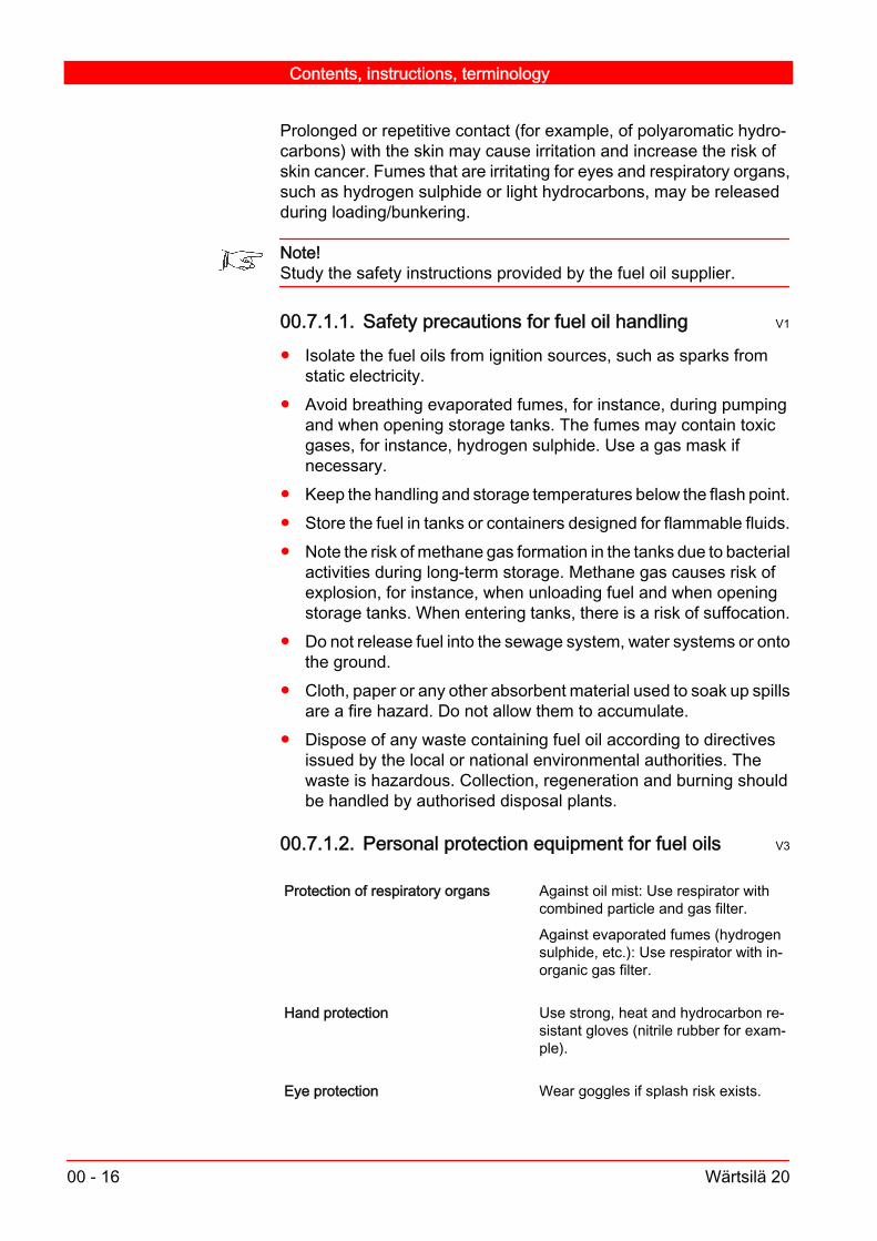
Prolonged or repetitive contact (for example, of polyaromatic hydro‐carbons) with the skin may cause irritation and increase the risk ofskin cancer. Fumes that are irritating for eyes and respiratory organs,such as hydrogen sulphide or light hydrocarbons, may be releasedduring loading/bunkering.
Note!Study the safety instructions provided by the fuel oil supplier.
00.7.1.1. Safety precautions for fuel oil handling V1
Isolate the fuel oils from ignition sources, such as sparks fromstatic electricity.
Avoid breathing evaporated fumes, for instance, during pumpingand when opening storage tanks. The fumes may contain toxicgases, for instance, hydrogen sulphide. Use a gas mask ifnecessary.
Keep the handling and storage temperatures below the flash point. Store the fuel in tanks or containers designed for flammable fluids. Note the risk of methane gas formation in the tanks due to bacterial
activities during long-term storage. Methane gas causes risk ofexplosion, for instance, when unloading fuel and when openingstorage tanks. When entering tanks, there is a risk of suffocation.
Do not release fuel into the sewage system, water systems or ontothe ground.
Cloth, paper or any other absorbent material used to soak up spillsare a fire hazard. Do not allow them to accumulate.
Dispose of any waste containing fuel oil according to directivesissued by the local or national environmental authorities. Thewaste is hazardous. Collection, regeneration and burning shouldbe handled by authorised disposal plants.
00.7.1.2. Personal protection equipment for fuel oils V3
Protection of respiratory organs Against oil mist: Use respirator withcombined particle and gas filter.
Against evaporated fumes (hydrogensulphide, etc.): Use respirator with in‐organic gas filter.
Hand protection Use strong, heat and hydrocarbon re‐sistant gloves (nitrile rubber for exam‐ple).
Eye protection Wear goggles if splash risk exists.
Contents, instructions, terminology
00 - 16 Wärtsilä 20

Skin and body protection Wear facial screen and coveringclothes as required.
Use safety footwear when handlingbarrels.
Wear protective clothing if hot productis handled.
00.7.1.3. First aid measures for fuel oil accidents V3
Inhalation of fumes Move the victim to fresh air.
Keep the victim warm and lying still.
Give oxygen or mouth to mouth resus‐citation if needed.
Seek medical advice after significantexposure or inhalation of oil mist.
Skin contact If the oil was hot, cool the skin immedi‐ately with plenty of cold water.
Wash immediately with plenty of waterand soap.
Do not use solvents as they will dis‐perse the oil and might cause skin ab‐sorption.
Remove contaminated clothing.
Seek medical advice if irritation devel‐ops.
Eye contact Rinse immediately with plenty of water,for at least 15 minutes.
Seek medical advice.
If possible, keep rinsing until eye spe‐cialist has been reached.
Ingestion Rinse the mouth with water.
Do not induce vomiting as this maycause aspiration into the respiratory or‐gans.
Seek medical advice.
Contents, instructions, terminology
Wärtsilä 20 00 - 17

00.7.2. Lubricating oils V1
Fresh lubricating oils normally present no particular toxic hazard, butall lubricants should always be handled with great care.Used lubricating oils may contain significant amounts of harmful metaland PAH (polyaromatic hydrocarbon) compounds. Avoid prolongedor repetitive contact with the skin. Prevent any risk of splashing. Keepaway from heat, ignition sources and oxidizing agents.There is a risk of long term contamination of the soil and the groundwater. Take every appropriate measure to prevent water and soilcontamination.
Note!Study and follow the safety information provided by the supplier of thelubricating oil.
00.7.2.1. Safety precautions for handling lubricating oil V1
When handling lubrication oils: Ensure adequate ventilation if there is a risk of vapours, mists or
aerosols releasing. Do not breathe vapours, fumes or mist. Keep the oil away from flammable materials and oxidants. Keep the oil away from food and drinks. Do not eat, drink or smoke
while handling lubricating oils. Use only equipment (containers, piping, etc.) that are resistant to
hydrocarbons. Open the containers in well ventilatedsurroundings.
Immediately take off all contaminated clothing.Note also the following: Empty packaging may contain flammable or potentially explosive
vapours. Cloth, paper or any other absorbent material used to recover spills
are fire hazards. Do not allow these to accumulate. Keep wasteproducts in closed containers.
Waste containing lubricating oil is hazardous and must bedisposed of according to directives issued by the local or nationalenvironmental authorities. Collection, regeneration and burningshould be handled by authorised disposal plants.
Contents, instructions, terminology
00 - 18 Wärtsilä 20

00.7.2.2. Personal protection equipment for lubricatingoils V3
Hand protection Use impermeable and hydrocarbon re‐sistant gloves (nitrile rubber for exam‐ple).
Eye protection Wear goggles if splash risk exists.
Skin and body protection Wear facial screen and coveringclothes as required.
Use safety footwear when handlingbarrels.
Wear protective clothing when han‐dling hot products.
00.7.2.3. First aid measures for accidents with lubricatingoil V3
Inhalation of fumes Move the victim to fresh air.
Keep the victim warm and lying still.
Skin contact Wash immediately with plenty of waterand soap or cleaning agent.
Do not use solvents (the oil is dis‐pearsed and may be absorbed into theskin).
Remove contaminated clothing. Seekmedical advice if irritation develops.
Eye contact Rinse immediately with plenty of water,and continue for at least 15 minutes.
Seek medical advice.
Ingestion Do not induce vomiting, in order toavoid the risk of aspiration into respira‐tory organs.
Seek medical advice immediately.
Aspiration of liquid product If aspiration into the lungs is suspected(during vomiting for example) seekmedical advice immediately.
Contents, instructions, terminology
Wärtsilä 20 00 - 19

00.7.3. Cooling water additives, nitrite based V1
The products are toxic if swallowed. Concentrated product may causeserious toxic symptoms, pain, giddiness and headache. Significantintake results in greyish/blue discoloration of the skin and mucusmembranes and a decrease in blood pressure. Skin and eye contactwith the undiluted product can produce intense irritation. Diluted sol‐utions may be moderately irritating.
Note!Study the safety information provided by the supplier of the product.
00.7.3.1. Safety precautions for handling cooling wateradditives V1
Avoid contact with skin and eyes. Keep the material away from food and drinks. Do not eat, drink or
smoke while handling it. Keep the material in a well ventilated place with access to safety
shower and eye shower. Soak up liquid spills in absorbent material and collect solids in a
container. Wash floor with water as spillage may be slippery.Contact appropriate authorities in case of bigger spills.
Bulk material can be land dumped at an appropriate site inaccordance with local regulations.
00.7.3.2. Personal protection equipment for cooling wateradditives V2
Respiratory protection Normally no protection is required.
Avoid exposure to product mists.
Hand protection Wear rubber gloves (PVC or naturalrubber for example).
Eye protection Wear eye goggles.
Skin and body protection Use protective clothing and take careto minimise splashing.
Use safety footwear when handlingbarrels.
Contents, instructions, terminology
00 - 20 Wärtsilä 20
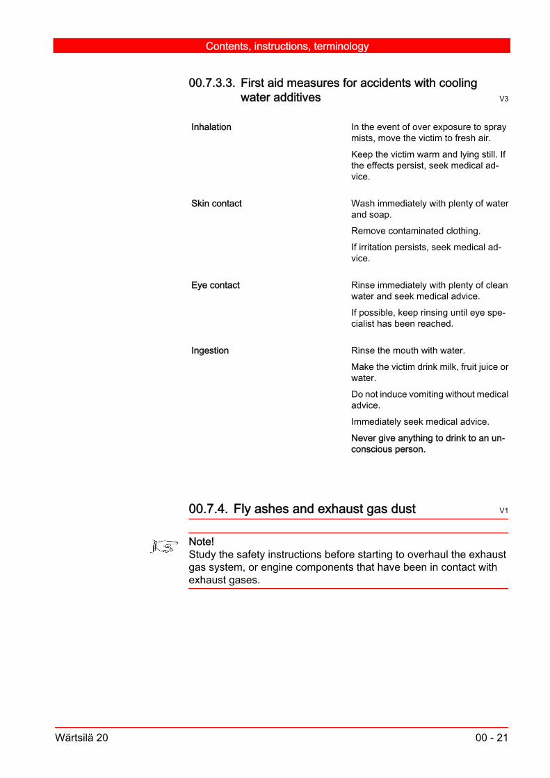
00.7.3.3. First aid measures for accidents with coolingwater additives V3
Inhalation In the event of over exposure to spraymists, move the victim to fresh air.
Keep the victim warm and lying still. Ifthe effects persist, seek medical ad‐vice.
Skin contact Wash immediately with plenty of waterand soap.
Remove contaminated clothing.
If irritation persists, seek medical ad‐vice.
Eye contact Rinse immediately with plenty of cleanwater and seek medical advice.
If possible, keep rinsing until eye spe‐cialist has been reached.
Ingestion Rinse the mouth with water.
Make the victim drink milk, fruit juice orwater.
Do not induce vomiting without medicaladvice.
Immediately seek medical advice.
Never give anything to drink to an un‐conscious person.
00.7.4. Fly ashes and exhaust gas dust V1
Note!Study the safety instructions before starting to overhaul the exhaustgas system, or engine components that have been in contact withexhaust gases.
Contents, instructions, terminology
Wärtsilä 20 00 - 21

00.7.4.1. Precautions for handling fly ashes and exhaustgas dust V1
When handling fly ashes, exhaust gas dust or any contaminatedcomponents, observe the following requirements and precautions: Avoid inhaling and swallowing fly ashes and dusts. Prevent eye
and skin contacts. Avoid spreading and spilling the fly ashes and dusts to the
environment. Take measures to avoid spreading the dust in the surrounding
area when opening the manholes of the exhaust gas system,especially the Selective Catalytic Reduction (SCR) system (ifincluded). Avoid spreading dust when handling exhaust gassystem components.
Take care that the ventilation is suitable when collecting dustarisen during the machining and cleaning of the components.
Apply appropriate disposal instructions for flue gas dust spillage.The dust collected from the exhaust gas system must beconsidered as hazardous waste. It must be treated according tothe local regulations and legislation.
00.7.4.2. Personal protection equipment for fly ashes andexhaust gas dust V3
Respiratory organ protection Use P3 filter respirator against toxicparticles.
For work inside the SCR or other pla‐ces in the exhaust gas system, wherethe dust concentration is high, a respi‐ration mask with fresh filtered com‐pressed air supply is recommended.
Hand protection Use gloves.
Eye protection Wear goggles.
Skin and body protection Wear covering clothes.
Use proper protection also when machining or cleaning engine com‐ponents that have been in contact with exhaust gases.
Contents, instructions, terminology
00 - 22 Wärtsilä 20

00.7.4.3. First aid measures for fly ash and exhaust gasaccidents V3
Inhalation of ashes Move the victim to fresh air.
Keep the victim warm and lying still.
Give oxygen or mouth to mouth resus‐citation if needed.
Seek medical advice after a significantexposure.
Skin contact If the ash is hot, cool the skin immedi‐ately with plenty of cold water.
Wash immediately with plenty of waterand soap.
Do not use solvents as it disperses theash and may cause skin absorption.
Remove contaminated clothing.
Seek medical advice if irritation devel‐ops.
Eye contact Rinse immediately with plenty of waterfor at least 15 minutes and seek medi‐cal advice.
If possible, keep rinsing until eye spe‐cialist has been reached.
Ingestion Rinse the mouth with water.
Do not induce vomiting as it may causeaspiration into respiratory organs.
Seek medical advice.
00.7.5. Lead in bearings V1
Lead has valuable lubricating properties and is therefore incorporatedinto many bearing alloys.The bearings in Wärtsilä engines contain lead and are therefore toxic.Bearings that are to be scrapped and contain lead must be disposedof according to the local authority regulations.
Contents, instructions, terminology
Wärtsilä 20 00 - 23

00.7.6. Fluoride rubber products
00.7.6.1. Precautions when handling fluoride rubberproducts V2
Normal sealing applicationsIn normal sealing applications the use of fluoride rubber productsdoes not cause any health hazards. The products can be handledwithout any risk provided that normal industrial hygiene is maintained.
When changing O-rings of valve seatsAlways wear protective rubber gloves when changing the O-rings ofthe valve seats.
When handling the remains of burnt fluoride rubberWhen handling the remains of burnt fluoride rubber, for instance,when changing O-rings after a valve blow-by, wear impenetrable acid-proof gloves to protect the skin from the highly corrosive remains.Appropriate glove materials are neoprene or PVC. All liquid remainsmust be considered to be extremely corrosive.The remains can be neutralized with large amounts of calcium hy‐droxide solution (lime water). Used gloves must be disposed of.
Grinding dustDust and particles originating from grinding or abrasion (wear) of flu‐oride rubber may when burned form toxic degradation products.Smoking must therefore be prohibited in areas where fluoride rubberdust and particles are present.
In case of fireWhen burned fluoride rubber can cause the formation of toxic andcorrosive degradation products, for example, hydrofluoric acid, car‐bonyl fluoride, carbon monoxide, and carbon fluoride fragments of lowmolecular weight.Operators handling the remains of burnt fluoride rubber must wearimpenetrable acid-proof gloves to protect the skin from the highly cor‐rosive remains. Appropriate glove materials are neoprene or PVC. Allliquid state remains must be considered extremely corrosive.Burning (incineration) of fluoride rubber is allowed only when ap‐proved incinerators equipped with gas emission reduction systemsare used.
Contents, instructions, terminology
00 - 24 Wärtsilä 20
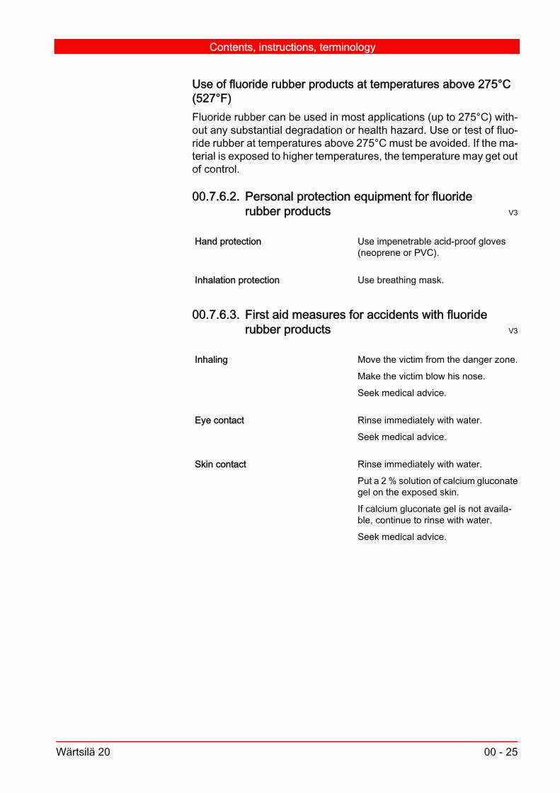
Use of fluoride rubber products at temperatures above 275°C(527°F)Fluoride rubber can be used in most applications (up to 275°C) with‐out any substantial degradation or health hazard. Use or test of fluo‐ride rubber at temperatures above 275°C must be avoided. If the ma‐terial is exposed to higher temperatures, the temperature may get outof control.
00.7.6.2. Personal protection equipment for fluoriderubber products V3
Hand protection Use impenetrable acid-proof gloves(neoprene or PVC).
Inhalation protection Use breathing mask.
00.7.6.3. First aid measures for accidents with fluoriderubber products V3
Inhaling Move the victim from the danger zone.
Make the victim blow his nose.
Seek medical advice.
Eye contact Rinse immediately with water.
Seek medical advice.
Skin contact Rinse immediately with water.
Put a 2 % solution of calcium gluconategel on the exposed skin.
If calcium gluconate gel is not availa‐ble, continue to rinse with water.
Seek medical advice.
Contents, instructions, terminology
Wärtsilä 20 00 - 25

Contents, instructions, terminology
00 - 26 Wärtsilä 20

01. Main Data, Operating Data and GeneralDesign V2
01.1. Main data for Wärtsilä 20 V6
Cylinder bore.........................................................................200 mmStroke....................................................................................280 mmPiston displacement per cylinder...............................................8.80 l
Firing orderEngine type Clockwise rotation Counter-clockwise rotation
4L20 1-3-4-2 1-2-4-35L20 1-2-4-5-3 1-3-5-4-26L20 1-5-3-6-2-4 1-4-2-6-3-58L20 1-3-7-4-8-6-2-5 1-5-2-6-8-4-7-39L20 1-7-4-2-8-6-3-9-5 1-5-9-3-6-8-2-4-7
Normally the engine rotates clockwise.
Lubricating oil volume in the engineEngine type 4L20 5L20 6L20 8L20 9L20App. oil volume in litres
Normal sump270 320 380 490 550
Deep sump 330 500 640 710Special deep sump 540Oil volume between max..and min. marks
appr. litres/mm
0.7 1.4 1.5 1.9 2.0
App. cooling water volume (HT) in the engine in litresEngine type 4L20 5L20 6L20 8L20 9L20Engine only 90 105 120 150 160
Lubricating oil volume in the speed governor in litresWoodward 3161 2.2Woodward UG-A 1.4Regulateurs Europa 2221, 2231 2
Main Data, Operating Data and General Design
Wärtsilä 20 01 - 1

01.2. Recommended operating data V3
Apply to normal operation at nominal speed.
Temperatures, (°C)Normal values (xx) Alarm (stop) limits (xx)
Load 100 % 0 - 100 %Lube oil before engine 63 - 67 80Lube oil after engine 10 - 15
higherHT water after engine 86 - 95 105 (110)HT water before engine 6 - 10 lowerLT water before charge air cooler 25 - 38Charge air in air receiver 50 - 70 75Exhaust gas after cylinder See test records 70 higher (xxx)Preheating of HT water 60
Gauge pressures (bar)Normal values (xx) Alarm (stop) limits (xx)
Load 100 % 0 - 100 %Lube oil before engine at a speed of 720RPM (12.0 r/s)
4.0 - 5.0 3.0 (2.0)
1000 RPM (16.7 r/s) 4.0 - 5.0 3.0 (2.0)HT/LT water before HT/LT pump (=stat‐ic)
0.7 -1.5
HT water before engine 1.6 + static press. (x) 1.0 or 0.2 + static press. (x)LT water before charge air cooler 1.6 + static press.(x) 1.0 or 0.2 + static press. (x)Fuel before engine (MD) 4 - 7 (x), (HF) 5 - 7 4Compressed air
Air starter
max. 30
9.0
18
Charge air See test records
Other pressures (bar)Normal values (xx) Alarm (stop) limits (xx)
Load 100 % 0 - 100 %Firing pressure See test recordsOpening pressure of safety valve onlube oil pump
6 - 8
Visual indicator and electronic alarm forhigh pressure drop over lube oil filter
<1.2 - 1.8 1.2 - 1.8
(x) Depending on speed and installation
Main Data, Operating Data and General Design
01 - 2 Wärtsilä 20

With engine driven MD-pump pressure might be lower close to min.speed.(xx) Under 30% load the lubricating oil and water temperatures fall alittle.(xxx) See test records.
01.3. Reference conditions V2
Reference conditions according to ISO 3046/I (2002):Air pressure.............................................................100 kPa (1.0 bar)Ambient temperature.....................................................298 K (25°C)Relative air humidity....................................................................30%Cooling water temperature of charge air cooler.............298 K (25°C)In case the engine power can be utilized under more difficult condi‐tions than those mentioned above, it will be stated in the sales docu‐ments. Otherwise, the engine manufacturer can give advice about thecorrect output reduction. As a guideline additional reduction may becalculated as follows:
Reduction factor = (a + b + c) %
a=0.5% for every °C the ambient temperature exceeds the statedvalue in the sales documents.b=1% for every 100 m level difference above stated value in the salesdocuments.c=0.4% for every °C the cooling water of the charge air cooler ex‐ceeds the stated value in the sales documents.
01.4. General engine design V5
The engine is a turbocharged intercooled 4-stroke diesel engine withdirect fuel injection.The engine block is cast in one piece. The main bearings are hanging.The main bearing cap is supported by two hydraulically tensionedmain bearing screws and two horizontal side screws.The charge air receiver is cast into the engine block as well as thecooling water header. The crankcase covers, made of light metal, sealagainst the engine block by means of rubber sealings.
Main Data, Operating Data and General Design
Wärtsilä 20 01 - 3

The lubricating oil sump is welded.The cylinder liners are of wet type. The cooling effect is optimised togive the correct temperature to the inner surface.To eliminate the risk of bore polishing, the liner is provided with anantipolishing ring.The main bearings are fully interchangeable trimetal or bimetal bear‐ings which can be removed by removing the main bearing cap.The crankshaft is forged in one piece and is balanced by counter‐weights as required.The connecting rods are drop forged. The big end is split and themating faces are serrated. The small end bearing is stepped to ach‐ieve large bearing surfaces. The big end bearings are fully inter‐changeable trimetal or bimetal bearings.The pistons are of composite type with forged steel or casted skirt anda forged crown screwed together. It is fitted with a Wärtsilä patentedskirt lubricating system. The top ring grooves are hardened.Cooling oil enters the cooling space through the connecting rod. Thecooling spaces are designed to give an optimal shaker effect.The piston ring set consists of two chrome-plated compression ringsand one chrome-plated, spring-loaded oil scraper rings.The cylinder head, made of special cast iron, is fixed by four hydraul‐ically tensioned screws. The head has a double deck design andcooling water is forced from the periphery towards the centre givingefficient cooling in important areas.The inlet valves are stellited and the stems are chromium-plated. Thevalve seat rings are made of a special cast iron alloy and are change‐able.The exhaust valves also with stellited seats and chromium-platedstems and seal against the directly cooled valve seat rings.The seat rings, made of a corrosion and pitting resistant material, arechangeable.The camshafts are made up of one-cylinder pieces with integratedcams. The bearing journals are separate pieces and thus it is possibleto remove a camshaft piece sideways.The injection pumps have integrated roller followers and can bechanged without any adjustment. The pumps and piping are locatedin a closed space which is heat insulated for heavy fuel running. Theelement can be changed without removing the pump housing.The turbocharger is normally located at the free end of the engine.The charge air cooler is made as removable inserts.
Main Data, Operating Data and General Design
01 - 4 Wärtsilä 20

The lubricating oil system includes a gear pump, oil filter, cooler withthermostat valve, centrifugal by-pass filter and an electrically drivenprelubricating pump.The oil sump has the capacity to hold the entire volume of oil needed,and all cylinder numbers can be run in wet sump configuration. Drysump running is also possible.The starting system. The engine is provided with an air driven startingdevice of turbine type. The air starter acts directly on the flywheel.
Main Data, Operating Data and General Design
Wärtsilä 20 01 - 5

Main Data, Operating Data and General Design
01 - 6 Wärtsilä 20

02. Fuel, Lubricating Oil, Cooling Water V3
Note!For preventing and minimizing the handling risks, read carefully thechapter about Environmental Hazards.
02.1. Fuel V10
The Wärtsilä medium-speed diesel engine is designed to operate onheavy fuel (residual fuel) with a maximum viscosity of 700 cSt at 50°C (approx. 55 cSt at 100 °C, approx. 7200 Redwood No.1 secondsat 100 °F) and will operate satisfactorily on blended (intermediate)fuels of lower viscosity, as well as on distillate fuel. Avoid the use offuels having lower / higher injection viscosity than the values found inthe table below. The use of fuels having too low injection viscositymay lead to the seizure of fuel injection pump plunger or fuel injectionnozzle and will also increase fuel leakage in the injection pump lead‐ing to increased fuel consumption, deteriorated engine performanceand increased risk of cavitation in the fuel system.The following types of fossil fuels are defined for the Wärtsilä 20: HFO 1 & 2, ISO 8217:2005(E), ISO-F-RMH 700 and RMK 700 DO, diesel oil or LFO, light fuel oil Liquid bio fuel
Fuel viscosity limits at engine inlet in running conditions (cSt)Engine Type Fuel
LFO, min HFOWärtsilä 20 1,8 16 - 24
The maximum limits of fuel characteristics for a certain engine arestated in the documentation delivered with the engine.Blended fuels (residuals and distillate) with a viscosity between ap‐prox. 4 and 7 cSt at 100 °C (12 and 30 cSt at 50 °C, 75 and 200Redwood No.1 seconds at 100 °F) containing between 30 and 60 %distillate should, however, be avoided due to the risk of precipitationof heavy components in the blend, with filter clogging and largeamount of centrifuge sludge as a consequence.
Fuel, Lubricating Oil, Cooling Water
Wärtsilä 20 02 - 1

When difficulties with filter clogging are experienced, fuel incompati‐bility can be tested by the ASTM D4740-00 or ISO 10307-1/93 (LFO)or ISO 10307-2/A/93 (HFO) test methods.
02.1.1. Fuel treatment
02.1.1.1. Fuel separation V2
Separation principleMost fuels, except good quality distillate fuels (ISO-F-DMX, DMA andDMB) must be separated by a centrifugal separator before enteringthe engine. However, separation of distillate fuels must shall be con‐sidered, since fuels can get contaminated in storage tanks. The sep‐arator removes solid particles as small as 5 microns and additionallyfree water from the fuel very efficiently. Even smaller particles areseparated, but with reduced efficiency. There are several things to betaken into consideration, when designing the separation system. Thefollowing fuel parameters are the most important:ViscosityThe viscosity is very critical in determining the dimensions of the sep‐arator. Higher the fuel viscosity, lower the separation capacity. Thusa bigger separator size (or more separators) is required to separatethe same amount of fuel/hour. The separator manufactures have ta‐bles with flow capacities for standard fuel viscosities. Standard sep‐arators can handle fuels up to 700 cSt at 50°C. The viscosity is low‐ered as much as possible by heating the fuel to maximum tempera‐ture, which in standard HFO separators is 98°C. For liquid biofuelsthe separation temperature is typically 50-55°C. Higher separationtemperatures, more than 98°C can also be utilized. But these cannotbe handled by standard separators. Separators have to be designedfor each case. Higher separation temperatures are used with ex‐tremely high viscosity fuels. Separation temperature for distillate fuelis typically 40°C.DensityThe separation of water from fuel is based on the difference in densitybetween the two fluids. Water must always be heavier than the fuelto make the separation process possible. This limits the maximumdensity of the fuel to 1010 kg/m³ at 15°C for standard separators. Theseparation capacity is de-rated when the fuel densities are between990 and 1010 kg/m³ at 15°C. Fuels, with higher density than 1010 kg/m³ at 15°C, can be separated but this requires a special separatorincluding a water treatment system to increase the density of the op‐erating water. In that case it’s not possible to separate water from fuel,only solid particles.Flash point
Fuel, Lubricating Oil, Cooling Water
02 - 2 Wärtsilä 20

Flash point of heavy fuels varies a lot. Some heavy fuel qualities areat a temperature above their flash point and some below their flashpoint when separated. Distillate fuels are normally separated at atemperature below their flash point. For special fuels, like many crudeoils, having low flash point and containing light, easily evaporatingfractions, special explosion proof separators along with explosionproof electrical motors and other electrical components are needed.Also, with these fuels, a system to avoid explosion inside the sepa‐rator bowl is required. This is done by adding an inert gas. Thesesystems are expensive and are used only in special cases.Water contentIf the water content is >0.3% and the fuel density is >990 kg/m³ at15°C the separator is de-rated (see diagram below).Dimensioning of the separatorRequirement for the fuel separator unit flow is calculated accordingto the following formula:
V n b c fHFOS ENGE
FUEL
S•
ρ1100
×× × +⎛ ⎞⎜ ⎟⎝ ⎠
=
VHFOS = Required separator capacity [m3/h]nENG = Amount of engines [pcs]ρFUEL = Density at actual temperature [kg/m3]bE = Fuel consumption / Engine [kg/h]cS = Separator safety factor [minimum 15% is Alfa Laval’s recom‐mendation]f = Derating factor, depending on the fuel density and water content
Fuel, Lubricating Oil, Cooling Water
Wärtsilä 20 02 - 3

De-rating factor depending on the fuel density and water content
990 992 994 996 998 1000 1002 1004 1006 1008 1010
1
0,9
0,8
0,7
0,6
0,5
0,4
Density kg/m3 at 15 C
De-
ratin
g fa
ctor
Water content >0.5%Water content 0.3-0.5%Water content < 0.3%
Fig 02-1 V2
Separator modulesThe suppliers are making complete modules today, including heatersand feeder pumps, which means that the equipment is automaticallycalibrated and ready for customer use. The modules include a num‐ber of separators needed to meet the capacity of the installation alongwith an extra standby separator. This also ensures fuel supply whenone separator is in service.
02.1.1.2. Heating V2
See the diagram in Fig 02-2. In order to minimize the risk of wax for‐mation, keep the fuel temperature about 10 °C above the minimumstorage temperature indicated in the diagram. To compensate forheat losses between the heater and the engine, the temperature afterthe final heater should be 5 - 10 °C above the recommended tem‐perature before the injection pumps.
Fuel, Lubricating Oil, Cooling Water
02 - 4 Wärtsilä 20

Fuel oil viscosity-temperature diagram
C
-10 0 10 20 30 40 50 60 70 80 90 100 110 120 130 140 150
3
4
5
6789
10121416
202530
40506080
100
200300400600
1000
2000
5000
Centistokes
F
D
E
CK
BG
H
A
14 cSt at 40 C
GAS OIL
MARINE DIESEL OIL
11 cSt at 40 C
5.5 cSt at 40 C
APPROX. PUMPING LIMIT
VISCOSITY BEFORE
80 cSt at 50 C
180 cSt at 50 C
380 cSt at 50 C
700 cSt at 50 C
40 cSt at 50 C
FUEL PUMPS
CENTRIFUGING TEMPERATURE
TEMPERATUREMINIMUM STORAGE
MAX. TEMP
RECOMMENDEDRANGE
Fig 02-2 320261 V1
Example:A fuel oil with a viscosity of 380 cSt (A) at 50 °C (B) or 80cSt at 80 °C (C) must be preheated to 112 - 126 °C (D-E) before thefuel injection pumps, to 97 °C (F) at the centrifuge and to minimum40 °C (G) in storage tanks. The fuel oil may not be pumpable below36 °C (H).To obtain temperatures for intermediate viscosities, draw a line fromthe known viscosity/temperature point in parallel to the nearest vis‐cosity/temperature line in diagram.Example:Known viscosity 60 cSt at 50 °C (K). The following can beread along the dotted line: Viscosity at 80 °C = 20 cSt, temperatureat fuel injection pumps 74 - 86°C, centrifuging temperature 86 °C,minimum storage tank temperature 28 °C.The diagram in Fig 02-3 can be used for converting various viscosityunits to centistokes. The diagram should be used only for conversionof viscosities at the same temperature. The same temperature shouldthen be used when entering the viscosity/temperature point into thediagram in Fig 02-2.
Fuel, Lubricating Oil, Cooling Water
Wärtsilä 20 02 - 5

Note!When converting viscosities from one of the units on the abscissa tocentistokes or vice-versa, keep in mind that the result obtained is validonly at one and the same temperature. For converting the viscosityat a given temperature to a viscosity at another temperature, a vis‐cosity-temperature diagram or conversion rule must be used.
Viscosity conversion diagram
Centistokes
3
4
5
6789
1012141620253040506080
100
200300400600
1000
2000
5000
10 20 50 100 200 500 1000 2000 5000 10000Sec. Saybolt Furol
1 2 5 10 20 50 100 200 500 1000¡ Engler
10 20 50 100 200 500 1000 2000 5000 10000Sec.Redwood I
10 20 50 100 200 500 1000 2000 5000 10000Sec. Saybolt Universal
Fig 02-3 320253 V1
02.1.1.3. Viscosity control V2
An automatic viscosity controller, or a viscosimeter, at least, shouldbe installed in order to maintain the correct fuel injection viscosity be‐fore the fuel enters the engine’s fuel system.
Fuel, Lubricating Oil, Cooling Water
02 - 6 Wärtsilä 20

02.1.2. Maximum limits for fossil fuel characteristics V9
The diesel engine Wärtsilä 20, is designed and developed for con‐tinuous operation, without reduction of the rated output, on fossil fuelswith the following properties:
Heavy fuel oil:
Fuel characteristics, maximum limits Test method
referenceKinematic viscosity cSt at 100°C
cSt at 50°C
Redwood No.1 sec.at 100°F
55
700
7200
ISO 3104
Density kg/m3 at 15°C 991 ISO 3675 or12185
Density 1) kg/m3 at 15°C 10101) ISO 3675 or12185
Water % V/V 0.5 ISO 3733Water, max. before engine % V/V 0.3 ISO 3733Flash point, min. (PMCC) °C 60 ISO 2719Pour point °C 30 ISO 3016Total sediment potential % m/m 0.1 ISO 10307-2Sodium mg/kg 50 ISO 10478Sodium, bef. engine mg/kg 30 ISO 10478Al + Si bef. engine mg/kg 15 ISO 10478 or
IP 501 or 470
The limits above also correspond to the demands:
ISO 8217:2005(E), ISO-F-RMH 700 and RMK 7001)
BS MA 100:1996, RMH 55 and RMK 551)
CIMAC 2003, class H 55 and K 551).1) Provided the fuel treatment system can remove water and solids.The maintenance intervals are decided by the characteristics of theused fuel, see Chapter 04, Maintenance Schedule.
Fuel, Lubricating Oil, Cooling Water
Wärtsilä 20 02 - 7

The differences between HFO 1 and HFO 2 are seen below:
Fuel characteristics, maximum limits HFO 1 HFO 2 Test method
referenceSulphur % m/m 1.50 1.51 - 4.50 ISO 8754 or
14596Ash % m/m 0.05 0.06 - 0.15 ISO 6245
Vanadium mg/kg 100 101 - 600 ISO 14597 orIP 501 or 470
Al + Si mg/kg 30 31 - 80 ISO 10478 orIP 501 or 470
Conradson Carb. Residue % m/m 15.0 15.1 - 22.0 ISO 10370Asphaltens % m/m 8.0 8.1 - 14.0 ASTM D 3279
CCAI 850 851 - 870 ISO 8217,Annex B
Foreign substances or chemical waste, hazardous to the safety of theinstallation or detrimental to the performance of engines, should notbe contained in the fuel.
Note!If any of specified fuel properties exceed HFO 1 maximum value thefuel should be classified as HFO 2.
Fuel, Lubricating Oil, Cooling Water
02 - 8 Wärtsilä 20

Light fuel oil:The fuel specification is based on the ISO 8217:2005(E) standard andcovers the fuel categories ISO-F-DMX, DMA, DMB and DMC. Thedistillate grades mentioned above can be described as follows: DMX: A fuel which is suitable for use at ambient temperatures
down to -15 °C without heating the fuel. In merchant marineapplications, its use is restricted to lifeboat engines and certainemergency equipment due to reduced flash point.
DMA: A high quality distillate, generally designated MGO (MarineGas Oil) in the marine field.
DMB: A general purpose fuel which may contain trace amounts ofresidual fuel and is intended for engines not specifically designedto burn residual fuels. It is generally designated MDO (MarineDiesel Oil) in the marine field.
DMC: A fuel which can contain a significant proportion of residualfuel. Consequently it is unsuitable for installations where engineor fuel treatment plant are not designed for the use of residualfuels.
Fuel characteristics, maximum limits ISO-FDMX ISO-FDMA ISO-FDMB ISO-FDMC1) Test method
referenceAppearance Clear and bright - - Visual
inspectionViscosity, max.
Injection viscosity, min. 2)
Injection viscosity, max.2)
cSt at 40 °C
cSt
cSt
5.5
1.8
24
6
1.8
24
11
1.8
24
14
1.8
24
ISO 3104
Density, max. kg/m³ at 15°C
- 890 900 920 ISO 3675 or12185
Cetane index, min. 45 40 35 - ISO 4264Water max. % V/V - - 0.3 0.3 ISO 3733Sulphur, max. % m/m 1.00 1.50 2.003) 2.003) ISO 8754 or
14596
ASTM D 72124)
Ash, max. % m/m 0.01 0.01 0.01 0.05 ISO 6245Vanadium, max. mg/kg - - - 100 ISO 14597 or
IP 501 or 470Sodium, max. before engine2)
mg/kg - - - 30 ISO 10478
Aluminium + Silicon, max. mg/kg - - - 25 ISO 10478 orIP 501 or 470
Aluminium + Silicon, max.before engine 2)
mg/kg - - - 15 ISO 10478 orIP 501 or 470
Fuel, Lubricating Oil, Cooling Water
Wärtsilä 20 02 - 9

Fuel characteristics, maximum limits ISO-FDMX ISO-FDMA ISO-FDMB ISO-FDMC1) Test method
referenceCarbon residue, max.
Carbon residue on 10 % V/Vdistillation bottoms, max.
% m/m -
0.30
-
0.30
0.30
-
2.50
-
ISO 10370
Flash point (PMCC), min. °C 60 2) 60 60 60 ISO 2719Pour point, max.
- winter quality
- summer quality
°C
-
-
- 6
0
0
6
0
6
ISO 3016
Cloud point, max. °C -16 - - - ISO 3015Total sediment existent, max. % m/m - - 0.1 0.1 ISO 10307-1Used lubricating oil 5)
- calcium, max.
- zinc, max.
- phosphorus, max.
mg/kg
-
-
-
-
-
-
-
-
-
30
15
15
IP 501 or 470
IP 501 or 470
IP 501 or 500
1)Use of ISO-F-DMC category fuel is allowed provided that the fueltreatment system is equipped with a fuel centrifuge.2)Additional properties specified by the engine manufacturer, whichare not included in the ISO specification or differ from the ISO spec‐ification.3)A sulphur limit of 1,5 % m/m will apply in SOx emission controlledareas designated by International Maritime Organization. There maybe also other local variations.4)For fuels having sulphur content below 0,05 % m/m5)A fuel shall be considered to be free of used lubricating oil (ULO), ifone or more of the elements calcium, zinc and phosphorus are belowor at the specified limits. All three elements shall exceed the samelimits before a fuel shall be deemed to contain ULO.The fuel should not include any added substance or chemical waste,which jeopardizes the safety of installations or adversely affects theperformance of the engines or is harmful to personnel or contributesoverall to additional air pollution.
02.1.3. Maximum limits for liquid biofuelcharacteristics V2
The Wärtsilä 20 diesel engines are designed and developed for con‐tinuous operation, without reduction in the rated output, on crude liq‐uid biofuels or biodiesels with the properties included in Tables 1 and
Fuel, Lubricating Oil, Cooling Water
02 - 10 Wärtsilä 20

2. However, since liquid biofuels typically have lower heating valuethan fossil fuels, capacity of the fuel injection system must be checkedcase specifically.The crude liquid biofuel specification included in Table 1 is valid forcrude vegetable based biofuels, like palm oil, coconut oil, copra oil,rape seed oil, jathropha oil, etc. but is not valid for animal based bio‐fuels.The biodiesel specification in Table 2 is valid for renewable refinedliquid biofuels, including both 1st and 2nd generation biodiesels,which are manufactured by using transesterification or hydrogenationprocesses. Renewable refined liquid biofuels can contain both vege‐table and / or animal based raw material and do normally show outvery good physical and chemical properties and can be used as wellprovided that the specification included in the Table 2 is fulfilled. In‐ternational standards ASTM D 6751-06 or EN 14214:2003 (E) aretypically used for specifying biodiesel quality.Blending of different fuel qualities:Crude liquid biofuels must not be mixed with fossil fuels, but have tobe used as such.Mixing of crude liquid biofuel and distillate fuel will increase the riskof cavitation in the fuel system, since required fuel temperature beforeengine is normally 65 – 75 °C. At this temperature light fractions ofdistillate fuel start to already evaporate.Mixing of crude liquid biofuel with heavy fuel will increase the risk ofbiofuel component polymerization leading to formation of gummy de‐posits, since the use of heavy fuel would require much higher oper‐ating temperature than crude liquid biofuel, i.e. normally above 100°C in order to achieve a proper injection viscosity.Biodiesel on the other hand can be mixed with fossil distillate fuel.Fossil fuel being used as a blending component has to fulfil Wärtsilä’sdistillate fuel specification found for different the engine types fromthe documents: V92A0459, V92A0572 or V92A0670.Required fuel temperatures:Crude liquid biofuel temperature before an engine is an utmost im‐portant operating parameter. Too low temperature will cause solidifi‐cation of fatty acids leading to clogging of filters, plug formation in thefuel system and even to fuel injection equipment component break‐downs. Too high fuel temperature will increase the risk of polymeri‐zation, especially in the presence of oxygen. For liquid palm oil thefuel temperature before injection pumps shall be kept between 65 and75 °C. For other types of crude liquid biofuels the temperature re‐quirement can be slightly different and must be confirmed before theuse.Biodiesel temperature before fuel injection pumps has to be 45 ±5 °C.
Fuel, Lubricating Oil, Cooling Water
Wärtsilä 20 02 - 11
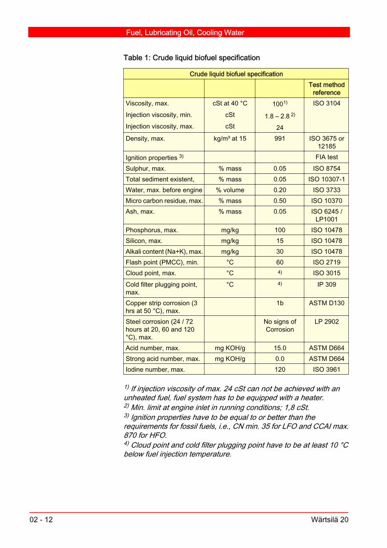
Table 1: Crude liquid biofuel specification
Crude liquid biofuel specification Test method
referenceViscosity, max.
Injection viscosity, min.
Injection viscosity, max.
cSt at 40 °C
cSt
cSt
1001)
1.8 – 2.8 2)
24
ISO 3104
Density, max. kg/m³ at 15 991 ISO 3675 or12185
Ignition properties 3) FIA testSulphur, max. % mass 0.05 ISO 8754Total sediment existent, % mass 0.05 ISO 10307-1Water, max. before engine % volume 0.20 ISO 3733Micro carbon residue, max. % mass 0.50 ISO 10370Ash, max. % mass 0.05 ISO 6245 /
LP1001Phosphorus, max. mg/kg 100 ISO 10478Silicon, max. mg/kg 15 ISO 10478Alkali content (Na+K), max. mg/kg 30 ISO 10478Flash point (PMCC), min. °C 60 ISO 2719Cloud point, max. °C 4) ISO 3015Cold filter plugging point,max.
°C 4) IP 309
Copper strip corrosion (3hrs at 50 °C), max.
1b ASTM D130
Steel corrosion (24 / 72hours at 20, 60 and 120°C), max.
No signs ofCorrosion
LP 2902
Acid number, max. mg KOH/g 15.0 ASTM D664Strong acid number, max. mg KOH/g 0.0 ASTM D664Iodine number, max. 120 ISO 3961
1) If injection viscosity of max. 24 cSt can not be achieved with anunheated fuel, fuel system has to be equipped with a heater.2) Min. limit at engine inlet in running conditions; 1,8 cSt.3) Ignition properties have to be equal to or better than therequirements for fossil fuels, i.e., CN min. 35 for LFO and CCAI max.870 for HFO.4) Cloud point and cold filter plugging point have to be at least 10 °Cbelow fuel injection temperature.
Fuel, Lubricating Oil, Cooling Water
02 - 12 Wärtsilä 20

Table 2: Biodiesel specification based on EN 14214:2003 standard
Biodiesel specification based on EN 14214:2003 standard Test method
referenceViscosity, min. - max.
Injection viscosity, min.
cSt at 40 °C
cSt
3,50 – 5,00
1,8 – 2,8 1)
EN ISO 3104
Density, min. - max. kg/m³ at 15 860 - 900 EN ISO 3675 /12185
Cetane number, min. 51,0 EN ISO 5165Sulphur content, max. mg/kg 10,0 prEN ISO
20846 / 20884Sulphated ash content,max.
% m/m 0,02 ISO 3987
Total contamination, max. mg/kg 24 EN 12662Water content, max. mg/kg 500 EN ISO 12937Carbon residue (on 10%distillation residue), max.
% m/m 0.30 EN ISO 10370
Phosphorus content, max. mg/kg 10,0 EN 14107Group I metals (Na + K)content, max.
mg/kg 5,0 EN 14108 /14109
Group II metals (Ca + Mg)content, max.
mg/kg 5,0 prEN 14538
Flash point, min. °C 120 prEN ISO3679
Cold filter plugging point,max. (climate dependentrequirement)
°C -44 => +5 EN 116
Oxidation stability at 110°C, min.
hrs 6,0 EN 14112
Copper strip corrosion (3hrs at 50 °C), max.
Rating Class 1 EN ISO 2160
Acid value, max. mg KOH/g 0,50 EN 14104Iodine value, max. g iodine / 100 120 EN 14111Ester content, min. % m/m 96,5 EN 14103Linolenic acid methyl ester,max.
% m/m 12,0 EN 14103
Polyunsaturated methylesters, max.
% m/m 1
Methanol content, max. % m/m 0,20 EN 14110Monoglyceride content,max.
% m/m 0,80 EN 14105
Diglyceride content, max. % m/m 0,20 EN 14105
Fuel, Lubricating Oil, Cooling Water
Wärtsilä 20 02 - 13

Biodiesel specification based on EN 14214:2003 standard Test method
referenceTriglyceride content, max. % m/m 0,20 EN 14105Free glycerol, max. % m/m 0,02 EN 14105 /
14106Total glycerol, max. % m/m 0,25 EN 14105
1) Min. limit at engine inlet in running conditions; 1,8 cSt.
02.1.4. Comments on fuel characteristics V8
ViscosityThe viscocity is not a measure of the fuel quality, but determines thecomplexibility of the fuel heating and handling system, as the HFOhas to be heated to reach required viscosity at the point of injection.At low viscosities, the flow past the plunger in the injection pump in‐creases. This leads to a decrease in the amount of injected fuel, whichin bad cases might make it impossible to reach full engine output. Thestandard engine fuel system is laid out for max. 700 cSt at 50 °C fuel(approx. 55 cSt at 100°C, approx. 7200 Redwood No. 1 seconds at100°F).
DensityThe density influences mainly on the fuel separation. Separators canremove water and to some extent solid particles from fuels havingdensities of up to 991 kg/m 3 at 15°C. There are also separators onthe market that can clean fuel with densities of up to 1010 kg/m3 at15°C. The separator capability must be checked before purchasing afuel with a very high density, as a bad separation will lead to abnormalwear due to unremoved particles and water. If an older design fuelseparator is used, the separator’s gravity disc must be chosen ac‐cording to the fuel density.
Caution!Fuels having a low viscosity in combination with a high density usuallyhave bad ignition properties!
Ignition qualityHeavy fuels may have very low ignition quality. This may cause trou‐ble at start and low load operation, particularly if the engine is notsufficiently preheated. Low ignition quality may also result in a longignition delay and can cause a fast pressure rise and very high max‐imum pressures. This increases the mechanical load and can evendamage engine components such as e.g. piston rings and bearings
Fuel, Lubricating Oil, Cooling Water
02 - 14 Wärtsilä 20

severely. Deposits on the piston top, on the exhaust valves, in theexhaust system, and on the turbine nozzle ring and turbine bladescan also be expected. The turbocharger fouling will lead to decreasedturbocharger efficiency, and increased thermal load.A symptom of low ignition quality is diesel knock, i.e. hard, high pitch‐ed combustion noise. The effects of diesel knocking are increasedmechanical load on components surrounding the combustion space,increased thermal load, as well as increased lubricating oil consump‐tion and contamination.
Caution!Although low ignition quality produces long ignition delay, advancingthe injection timing makes things only worse: fuel is injected at a lowercompression temperature, and this will produce an even longer igni‐tion delay!
Ignition quality is not defined, nor limited, in marine residual fuelstandards. The same applies to ISO-F-DMC marine distillate fuel.The ignition quality of a distillate fuel can be determined according toseveral methods, i.e. Diesel Index, Cetane Index, and Cetane Num‐ber. The ignition quality of a heavy fuel oil can be roughly determinedby calculating the CCAI (= Calculated Carbon Aromaticity Index) fromthe viscosity and density of a fuel.Formula for determining CCAI:
CCAI =ρ- 81 - 141 log10log10(νk+ 0.85)
Where:
ρ = density (kg/m3 at 15°C)νk = kinematic viscosity ( cSt at 50 °C)
Note!An increased CCAI value indicates decreased ignition quality.
CCAI can also be determined (but with limited accuracy) by the nomo‐gram, see Fig 02-4.
Fuel, Lubricating Oil, Cooling Water
Wärtsilä 20 02 - 15

Nomogram for determining CCAI
820
840
860
880
900
920
940
960
980
1000
1020
1040
800
810
820
830
840
850
860
870
880
890
900
910
920
930
4
5
6
7
89
10
15
20
2530354050
75
100
150
200250300400500
7501000
2
3
4
5
6
78910
15
20
253035405060
VISCOSITYcSt (mm2/s)
CCAIDENSITY(kg/m3 at 15˚C)
50˚C at 100˚C
Fig 02-4 320259 V1
Straight run fuels show CCAI values in the 770 - 840 range, and arevery good igniters. Cracked residues may run from 840 to over 900,while most bunkers remain in the 840 to 870 range at present.The CCAI is not an exact tool for judging fuel ignition. Following roughguidelines can however be given: Engines running at constant speed and load over 50 % can without
difficulty use fuels with CCAI-values of up to 870. Engines running at variable speed and load can without difficulty
run on fuels with CCAI-values up to 860.To avoid difficulties with poor ignition quality fuels the following shouldbe noted: Sufficient preheating of the engine before start. Proper function of the cooling system. Proper function of the injection system, especially the injection
nozzle condition must be good.
Fuel, Lubricating Oil, Cooling Water
02 - 16 Wärtsilä 20

Water contentThe water content of heavy fuel oils varies widely. Water may comefrom several different sources, it can either be fresh or salt. It can alsooriginate from e.g. condensation in the installation's bunker tanks. If the water is sweet and very well emulgated in the fuel, the
effective energy content of the fuel decreases with increasingwater content, leading to an increase in fuel consumption.
If the fuel is contaminated with sea water, the chlorine in the saltwill cause corrosion of the fuel handling system, including theinjection equipment. The effects of sodium, that also originatesfrom salt, are described more in detail below.
To avoid problems and damage in the engine’s fuel injection system,the water content must be reduced to a max. 0.3 % before the engine.
SulphurSulphur in the fuel may cause cold corrosion and corrosive wear, es‐pecially at low loads. Together with vanadium and/or sodium sulphuralso contributes to deposit formation in the exhaust system, normallyin the form of sulphates. The deposits can also cause high tempera‐ture corrosion.
Ash contentA high ash content may be detrimental in several ways. Different ashcomponents can cause different problems: Aluminium and silicon oxides originate from the refining process,
and can cause severe abrasive wear mainly of the injection pumpsand nozzles, but also of cylinder liners and piston rings. Anefficient fuel separation is a must for minimising wear.
Oxides of vanadium and sodium , mainly sodium vanadylvanadates, are formed during the combustion, and mix or reactwith oxides and vanadates of other ash components, e.g. nickel,calcium, silicon and sulphur. The melting temperature of thecompound may be such, that ash particles stick to surfaces anddeposits are formed on a valve, in the exhaust gas system or inthe turbo-charger. This deposit is highly corrosive in the moltenstate, destroying the protective oxide layer on e.g. an exhaustvalve and leads to hot corrosion and a burned valve. Deposits andhot corrosion in the turbocharger, especially on the nozzle ring andturbine blades will cause a decreased turbocharger efficiency. Thegas exchange will be disturbed, less air flows through the engineand thus the thermal load on the engine increases. The depositformation increases at increased temperatures and engineoutputs.
Fuel, Lubricating Oil, Cooling Water
Wärtsilä 20 02 - 17

To avoid the above mentioned problems when running on high ashfuels, it is important to: Have an efficient fuel separation. Clean the turbocharger regularly with water. Have a strict quality control of the bunkered fuel, i.e. to see that
the amounts of ash and dangerous ash constituents stay low. Maintain clean air filters and charge air coolers by regular cleaning
based on pressure drop monitoring.
Carbon residue contentHigh carbon residue content may lead to deposit formation in thecombustion chamber and in the exhaust system, especially at lowloads. Deposit formation on injection nozzle tips will disturb the fuel
atomisation and deform the fuel sprays, decreasing thecombustion process efficiency, and even leading to locallyincreased thermal loads.
Deposits in the piston ring grooves and on the rings will hinder themovement of the rings, causing, among other things, increasedblow-by of combustion gases down to the crank case, which inturn increases the fouling of the lubricating oil.
Deposits in the exhaust gas system and in the turbocharger willdisturb the gas exchange and increase the thermal load.
Asphaltene contentAsphaltenes are complex, highly aromatic compounds with a highmolecular weight, that usually contain sulphur, nitrogen and oxygen,as well as metals like vanadium, nickel and iron (see "Ash" above). Ahigh asphaltene content indicates that a fuel may be difficult to igniteand that it burns slowly. If the fuel is unstable, asphaltenes may pre‐cipitate from the fuel and block filters and/or cause deposits in the fuelsystem, as well as excessive centrifuge sludge.High asphaltene content may contribute to deposit formation in thecombustion chamber and in the exhaust system, especially at lowloads.
Flash pointA low flash point (high vapour pressure) is often seen especially forcrude oils. The low flash point will not influence the combustion, butthe fuel can be dangerous to handle and store. This is especially thecase if the pour point is high, and the fuel has to be heated due tothis. Special explosion proof equipment and separators can be usedin extreme cases.
Fuel, Lubricating Oil, Cooling Water
02 - 18 Wärtsilä 20

A high vapour pressure (low flash point) can also cause cavitation andgas pockets in the fuel pipes. These can be avoided by using an ele‐vated pressure in the fuel handling system. It is to be noted that someinsurance companies demand the use of fuels having a flash pointhigher than 60°C.
Pour pointThe pour point tells at which temperature the fuel becomes so thickthat it does no longer flow. It determines how easy it will be to handlethe fuel. The whole fuel handling system, including tanks and pipes,must be heated to a temperature at least 10 - 15°C above the pourpoint.
Total sediment potentialTotal sediment potential (TSP) tells something about the fuel's sta‐bility. If the TSP is high, the danger of sediment and sludge formationin tanks and fuel handling systems increases, as well as the proba‐bility for filter clogging.TSP can also be used as a check for the compatibility of two differentfuels. For this purpose, samples of the two fuels are mixed. If the TSPfor the mix remains low, the fuels are compatible.
02.1.5. Measures to avoid difficulties when running onheavy fuel V2
Poor fuel quality will adversely influence wear, engine-part lifetimeand maintenance intervals.In order to obtain maximum operating economy it is recommendable:
a ) To limit maximum continuous output, as much as operating conditionsallow, if fuel is known or suspected to have high vanadium content(above 200 ppm) and sodium content.
b ) To limit low load operation, as much as operating conditions allow, iffuel is known or suspected to have high sulphur content (above 3mass-%), conradson carbon residue (above 12 mass-%) and/or as‐phaltene content (above 8 mass-%).Operation below 20 % of rated output should be limited to max. 100hours continuously, by loading the engine above 70 % of rated loadfor one hour before continuing the low load operation or shutting downthe engine.
Fuel, Lubricating Oil, Cooling Water
Wärtsilä 20 02 - 19

Idling (i.e. generator set disconnected) should be limited as much aspossible. Warming-up of the engine at no load for more than 3-5 mi‐nutes before loading, as well as idling for more than 3 minutes beforestopping, is unnecessary and should be avoided.
02.1.6. Using low sulphur & low viscosity distillate fuel(LFO) V7
Low fuel viscosity is generally speaking not a severe problem for 4-stroke engines, but can in severe cases damage the fuel injectionequipment and affect on the running parameters of the engine. In ex‐ceptional cases loss of capability to produce full power, black-out andstarting problems may also occur. Possible remedial actions againsttoo low viscosity are to specify minimum viscosity when ordering thefuel (LFO) or to design/modify the fuel systems to maintain appropri‐ate minimum viscosity by cooling.Wärtsilä does not specify any minimum sulphur content for the usedfuel. Based on present experience, lubricity is not considered a prob‐lem for 4-stroke fuel injection components as long as the sulphur (S)content is above ≈ 100 ppm (0.01 %). In some cases lubricity additivesare also used by fuel manufacturers and marketers in order to im‐prove lubricity properties of very low sulphur fuels. A common indus‐trial test is also available, based on the ISO 12156-1 standard “Dieselfuel – Assessment of lubricity using the high-frequency reciprocatingrig (HFRR)”. The recommended maximum limit, which is also typicallyspecified in other industrial applications, for this HFRR test is 460microns.If the sulphur content is below 100 mg/kg, it is also recommended tocarefully follow up any signs of increased wear in the fuel injectionpumps or exhaust valves / valve seats. If exhaust valve clearancesneed more frequent adjustments compared to earlier experience, it isa possible sign that fuel lubricity is not optimal. In this way a possibleproblems can also be detected before an excessive wear will occur.
02.1.7. General advice V4
To avoid stability and incompatibility problems (precipitation of heavycomponents in the fuel), avoid, if possible, blending fuels from differ‐ent bunker stations, unless the fuels are known to be compatible.If stability and compatibility problems occur, never add distillate fuel,as this will probably increase precipitation. A fuel additive with a highlypowerful dispersing characteristics can be of help until a new fuel de‐livery takes place.
Fuel, Lubricating Oil, Cooling Water
02 - 20 Wärtsilä 20

The characteristics of heavy fuels blended from residuals from mod‐ern refinery processes like catalytic cracking and visbreaking mayapproach at least some of the limit values of the fuel characteristics.Compared with "traditional" heavy fuels blended from straight run re‐siduals, the "modern" heavy fuels may have reduced ignition andcombustion quality.
Caution!Fuels blended from catalytic cracking residuals may contain veryabrasive catalytic fines (silicon and aluminium oxides) which, if al‐lowed to enter the injection system, may wear down injection pumpsand nozzles in a few hours.
Some of the difficulties that may occur when operating on heavy fuelsblended from cracked residuals can be avoided by: Sufficient centrifuging capacity. The best and most disturbance-
free results are obtained with the purifier and clarifier in series.Alternatively the main and stand-by separators may be run inparallel, but this makes heavier demands on correct gravity discchoice and constant flow and temperature control to achieveoptimum results. Flow rate through the centrifuges should notexceed the maximum fuel consumption by more than 10 %.
Sufficient heating capacity to keep centrifuging and injectiontemperatures at recommended levels. It is important that thetemperature fluctuations are as low as possible (±2 °C beforecentrifuge) when centrifuging high viscosity fuels with densitiesapproaching or exceeding 991 kg/m3 at 15 °C.
Sufficient preheating of the engine and the fuel systems beforestarting the engine.
Keeping fuel injection equipment and the inverse cooling systemin good condition.
02.2. Lubricating oil
02.2.1. Lubricating oil qualities V6
Lubricating oil is an integrated engine component and thus the qualityof it is upmost important. All lubricating oils, which have been ap‐proved for use in Wärtsilä 20 engine type, have gone through an ap‐proval test according to the engine manufacturer's procedure.
Fuel, Lubricating Oil, Cooling Water
Wärtsilä 20 02 - 21

The use of approved lubricating oil qualities during the warranty pe‐riod is mandatory and is also strongly recommended after the war‐ranty period.The list of approved lubricating oils can be found in Chapter 02B: Oilrequirements & oil quality.
Note!Never blend different oil brands unless approved by the oil supplier,and during the warranty period, by the engine manufacturer.
Note!Before using a lubricating oil not listed in the table, the engine man‐ufacturer must be contacted. The engine manufacturer has availablean approval procedure, which at need makes it possible to test newsuitable lubricating oil candidate formulations.
02.2.2. Maintenance and control of the lubricating oil V5
a ) Use of lubricating oil separator is mandatory for engines running onresidual fuel. It is optional for engines running on distillate fuel or nat‐ural gas. Continuous centrifuging of engine oil is recommended inorder to separate water and insolubles from the oil effectively.To achieve an effective result, the separation temperature recom‐mended by the separator manufacturers is 95 °C. This temperatureis also used to calculate the optimum flow rate. Please check with thelubricating oil supplier the optimal temperature range and use thehighest recommended temperature.With older design of separators, about 20% flow rate calculated fromthe rated capacity is recommended. But with new Alfa Laval SA/SUseries and Westfalia OSD series, the flow rate mentioned in the sizingtables must be used. In order to achieve optimum separation, theseparator must be capable of circulating the entire volume of oil, fourto five times every 24 hours, at the recommended flow rate.In theseparator types being equipped with a gravity disc, the right size ofthe disc can be chosen according to the lubricating oil density at theseparation temperature.Ensure that the separator’s conditioning water does not leak into thelubricating oil during separation, leading to increased water contentin the lubricating oil and possibly to depletion of additives ("washing").Follow the operation instructions given by the separator manufacturerfor optimal performance of the separator.
Fuel, Lubricating Oil, Cooling Water
02 - 22 Wärtsilä 20

Note!The lubricating oil separation efficiency influences the condition of thelubricating oil and the change interval of the lubricating oil batch. De‐pending on type of application and from the different lubricating oilsystem arrangements point of view, the following separation routinesare adviced:- Continous running of the separator(s) when the en‐gine(s) is running, recommended in the first place.- Periodical sepa‐ration of auxiliary engine in stand-by or running mode in installationequipped with one or more separator(s), which treats lubricating oil ofmore than one engine.
Caution!Defects on automatic, "self-cleaning" separators can quickly increasethe water content of the oil under certain circumstances! (The watercontrol valve fails.)
b ) During the first year of operation it is advisable to take samples of thelubricating oil at 500 operating hours intervals. The sample should besent to the oil supplier for analysis. On the basis of the results it ispossible to determine suitable intervals between oil changes. Fre‐quent oil analysis at 500 - 1000 operating hours intervals is also rec‐ommended after the first year of operation to ensure safe engine op‐eration. See also section 02.2.5., Handling of oil samples. When es‐timating the condition of the used oil, the following properties shouldbe observed. Compare with guidance values (type analysis) for newoil of the brand used.Viscosity. Should not decrease by more than 20% and not rise bymore than 25% above the guidance value at 100 °C.Should not de‐crease by more than 25 % and not rise by more than 45% above theguidance value at 40 °C.Flash point. Should not fall by more than 50 °C below the guidancevalue. Min. permissible flash point 190 °C (open cup) and 170 °C(closed cup) . At 150 °C risk of crankcase explosion.Water content. Should not exceed 0.3%. A value higher than 0.3%can not be accepted for longer periods, but measures must be taken;either centrifuging or oil change.BN (Base Number). Fuel categories A, B and F: The minimum allowable BN value of
a used oil is 50% of the nominal value of a new oil. Fuel categories C and D: The minimum allowable value of used
oil is BN 20.Insolubles. The quantity allowed depends on various factors. How‐ever, an n-Pentane insoluble value above 1.5% calls for attention. Avalue higher than 2% cannot be accepted for longer periods.
Fuel, Lubricating Oil, Cooling Water
Wärtsilä 20 02 - 23

In general it can be said that the changes in the analyses give a betterbasis of estimation than the absolute values.Fast and great changes may indicate abnormal operation of the en‐gine or of a system.
c ) Compensate for oil consumption by adding max. 10% new oil at atime. Adding larger quantities can disturb the balance of the used oilcausing, for example, precipitation of insolubles. Measure and recordthe quantity added. Attention to the lubricating oil consumption maygive valuable information about the engine condition. A continuousincrease may indicate that piston rings, pistons and cylinder liners aregetting worn, and a sudden increase motivates pulling the pistons, ifno other reason is found.
d ) Guidance values for oil change intervals are to be found in chapter04, Maintenance Schedule. Intervals between changes are influ‐enced by system size (oil volume), operating conditions, fuel quality,centrifuging efficiency and total oil consumption. Efficient centrifugingcan result in increased oil change intervals. It is recommended to fol‐low up that the BN value of the lubricating oil keeps within enginemanufacturer's limits during the whole oil change interval.
02.2.2.1. Changing the lubricating oil V7
When changing the lubricating oil, the following procedure is recom‐mended:
1 Empty the oil system while the oil is still hot. Be sure that oil filters andcoolers are also emptied.
2 Clean all the oil spaces with a high quality fibre and lint free cloth.Clean also the filters and camshaft compartment. Insert new filtercartridges.
3 Fill a small quantity of new oil in the oil sump and circulate with thepre-lubricating pump.
4 Fill required quantity of oil in the system. See chapter 01: Main Data,Operating data and General Design.Oil samples taken at regular intervals are analysed by the oil supplier.The results of this analysis is plotted as a function of operating hours.This is an efficient way of predicting oil change intervals. Ask the oilsupplier for copies of oil analysis report. Send it to the engine manu‐facturer for evaluation.
Fuel, Lubricating Oil, Cooling Water
02 - 24 Wärtsilä 20

When changing the lubricating oil brand from one to another followthe procedure given below. This minimizes the risk of lubricating oilfoaming, deposit formation, blocking of lubricating oil filters, damageof engine components, etc. If possible, change the lubricating oil brand during an engine (pis‐
ton) overhaul. Drain old lubricating oil from the lubricating oil system. Clean the lubricating oil system, if excessive amount of deposit
has formed on the surfaces of engine components like crankcase,camshaft compartment.
Fill the lubricating oil system with fresh lubricating oil.If the procedure described above is not followed, responsibility ofpossible damage and malfunctions caused by lubricating oil changeshould always be agreed between the oil company and customer.
02.2.3. Lubricating oil for the governor V11
See the Instruction Book for the governor, attached. An oil of viscosityclass SAE 30 or SAE 40 is suitable, and the same oil can be used asin the engine. Turbocharger oil can also be used in the governor. Inlow ambient conditions it may be necessary to use multigrade oil (e.g.SAE 5W-40) to get a good control during start-up. Oil change interval,see maintenance schedule chapter 04.Condensed water, high temperature or leaking drive shaft seal maycause the oil to deteriorate, or internal surfaces of the governor tocollect deposits. If the reason cannot be clarified and rectified, ashorter oil change interval or change of oil type should be considered.The governor should be flushed with the oil in use or gasoil if heavycontamination of the oil is evident.Examples of suitable lubricating oils for governor can be found fromthe end of this chapter, where the lists of approved lubricating oils foran engine and turbocharger are available. If the system is equipped with a start booster, then this should also
be emptied when changing oil. In installations whereby the actuator is equipped with a filter, it has
to be cleaned when changing oil. Depending on the governor type, oil should be separately emptied
from the power cylinder. This is done by removing the plug in thebottom of the power cylinder.
Some governors are equipped with a magnetic oil plug, this plugshould be cleaned in connection with an oil change.
Fuel, Lubricating Oil, Cooling Water
Wärtsilä 20 02 - 25

Caution!If turbine oil is used in the governor, take care not to mix it with enginelubricating oil. Only a small quantity of engine lubricating oil into theturbine oil may cause heavy foaming.
02.2.4. Lubricating oils for turbochargers V10
Please note that different types of turbochargers can be used for theengine. The lubricating system is different for the different turbo‐charger. One type of chargers has a common lubricating oil systemwith the engine, see chapter 15 (Turbocharging and air cooling), whilethe other type of chargers has an internal lubricating system for thebearings, See the Instruction Book for the turbocharger, attached.
Note!In the ABB VTR..4 series turbochargers the use of synthetic low fric‐tion lubricating oils is strongly recommended by the engine and theturbocharger manufacturers!
Oil change interval is 1500 h service for special mineral oils and 2500h service for synthetic lubricating oils.
Caution!Take care that the turbine oil is not mixed with engine lubricating oil.Only a small quantity may cause heavy foaming.
The list of approved lubricating oils for the ABB VTR..4 series turbo‐chargers can be found in the end of this chapter. These lubricatingoils are, regarding viscosity and quality, according to the recommen‐dations.
02.2.5. Handling of oil samples V2
When taking fuel oil or lubricating oil samples the importance of prop‐er sampling cannot be over-emphasised. The accuracy of the analy‐sis results depends significantly on proper sampling and the resultswill be only as good as the quality of the sample.Use clean sample containers holding approximately 1 litre. Cleansample containers and accessories (IATA carton boxes for transpor‐tation, ready made address labels, etc.) are available, for example,from Wärtsilä local network office. Rinse the sampling line properlybefore taking the actual sample. Preferably also rinse the samplebottles with the oil a couple of times before taking the sample, espe‐cially if "unknown" sample bottles need to be used. Close the bottles
Fuel, Lubricating Oil, Cooling Water
02 - 26 Wärtsilä 20

tightly using the screw caps provided. Seal all bottles and record allthe separate seal numbers carefully. Put the bottles to be sent foranalysing in "Ziploc" plastic bags to prevent any spillage. Gentlysqueeze the "Ziploc" bag to minimise any air content prior to sealing.The background information for the fuel oil/lubricating sample is asimportant as the sample itself. Oil samples with no background infor‐mation are of very limited value. The following data are essential tonote when taking the sample: Installation name Engine type and number Engine operating hours Lubricating oil brand/fuel oil type Lubricating oil operating hours The location where the lubricating oil/fuel oil sample was taken Sampling date and seal number of the separate samples, if seals
are available Reason for taking and analysing the sample Contact information: Name (of the person who took the sample),
telephone, fax, e-mail, etc.Use, for example, the ready made "Oil Analyse Application" form, seeInstruction Manual attachments .Observe personal safety precautions when taking and handling fueloil and lubricating oil samples. Avoid breathing oil fumes and mist,use respirator if necessary. Use strong, heat and hydrocarbon resist‐ant gloves (nitrile rubber for example). Wear eye goggles if splash riskexists. Wear facial screen and protecting clothes if hot product ishandled.
02.2.5.1. Lubricating oil sampling V1
Lubricating oil samples should be taken with the engine in operationimmediately after the lubricating oil filter on the engine. Always takelubricating oil samples before adding fresh oil to the system.
02.2.5.2. Fuel oil sampling V1
Fuel oil samples can be drawn from different places in the fuel oilsystem. Fuel samples "as bunkered" or "before the engine" (after fueloil separation and filtration) are perhaps the most common sampletypes. From the engines point of view the most important fuel oil sam‐ple is naturally the one which enters the engine, i.e. taken after fueloil separation and filtration. But if for example fuel oil separator effi‐ciency needs to be checked samples should be taken just before andafter the separator. It is not advisable to take samples from tank bot‐
Fuel, Lubricating Oil, Cooling Water
Wärtsilä 20 02 - 27
tom drain valves, since these will probably contain high levels of waterand sediment and thus the samples will not be representative of thebulk phase.
02.2.6. Dispatch and transportation V2
Place the bottle with the "Ziploc" bag inside the IATA carton box andfold the box according to the assembly instructions given on the box.Enclose a copy of the "Bunker Receipt", if available, before closingthe last flap on the IATA carton.Check the DNVPS Air Courier Directory and use appropriate label forthe IATA carton box to ensure that the sample is forwarded to thenearest DNVPS laboratory. Complete the courier dispatch instruc‐tions on the side of the IATA carton. Fill in the DNVPS universal ac‐count number to prevent rejection from the courier company (DHL).Complete the Proforma Invoice Form and tape it to the outside of theIATA carton.Call the air courier directly at the number as indicated in the Air Cou‐rier Directory and request urgent pick-up, if necessary. When thecourier arrives you will need to complete an Airway Bill.It is recommendable to handle the dispatching of the fuel oil and lu‐bricating oil samples at site. The results will be achieved faster whenthe dispatching is handled at site and additionally it is illegal to carryfuel oil samples as personal luggage on normal aeroplanes.Support with interpretation of the analysis results and advice on pos‐sible corrective actions is available from Wärtsilä, if needed.
02.3. Cooling water V1
In order to prevent corrosion, scale deposits or other deposits inclosed circulating water systems, the water must be treated with ad‐ditives.Before treatment, the water must be limpid and meet the specificationfound in the end of this chapter. Further, the use of an approved cool‐ing water additive or treatment system is mandatory.
Caution!Distilled water without additives absorbs carbon dioxide from the air,which involves great risk of corrosion.
Fuel, Lubricating Oil, Cooling Water
02 - 28 Wärtsilä 20

Sea water will cause severe corrosion and deposit formation even ifsupplied to the system in small amounts.Rain water has a high oxygen and carbon dioxide content; great riskof corrosion; unsuitable as cooling water.If risk of freezing occurs, please contact the engine manufacturer foruse of anti-freeze chemicals.Fresh water generated by a reverse osmosis plant onboard often hasa high chloride content (higher than the permitted 80 mg/l) causingcorrosion.
Caution!The use of glycol in the cooling water is not recommended, if it is notnecessary. Since glycol alone does not protect the engine againstcorrosion, additionally an approved cooling water additive must al‐ways be used!
02.3.1. Additives V8
As additives, use approved products from well-known and reliablesuppliers. In marine applications suppliers’ wide distribution networksmakes it easier to get the same product in different geographical lo‐cations.
Caution!The use of emulsion oils, phosphates and borates (sole) is not ac‐cepted.
In an emergency, if compounded additives are not available, treat thecooling water with sodium nitrite (NaNO2) in portions of 5 kg/m3. Toobtain a pH value of 9, add caustic soda (NaOH), if necessary.
Warning!Sodium nitrite is toxic. Handle with care and dispose all possible re‐siduals in accordance with valid environmental regulations.
Fuel, Lubricating Oil, Cooling Water
Wärtsilä 20 02 - 29

Corrosion rate as a function of nitrite concentration
B
A
Cor
rosi
on r
ate
X ppm Nitrite Concentration
To give full protection the Nitrite level should be kept above X ppm. The actual concentration is additive supplier dependent. A permanent lower level will lead to an accelerated corrosion rate.
Fig 02-5 320260 V1
Nitrite based cooling water additives are so called anodic inhibitorsand require proper dosing and maintenance in order to serve as in‐tended. The nitrite of the additive is as such a salt and it will increasethe conductivity of the water. The conductivity is on the other handone of the main parameters affecting the corrosion rate once a cor‐rosion process gets started, the higher the conductivity the higher thecorrosion rate.If the conditions (nitrite level, chlorides, pH, etc.) in the systems aresuch that the nitrite based additive is no longer able to protect theentire surface of the system there may occur a rapid, local corrosionin the areas that are not protected. The corrosion rate at the attackedareas will even be much greater than it would be with no additive atall present in the system, see schematic graph of the corrosion rateas a function of the nitrite dosage in Fig 02-5. Observe that the posi‐tion of the curve peak on the x-axis (= dangerous condition for corro‐sion) is not stable, but will shift depending on temperature, pH, chlor‐ides and sulphates contents, etc. in the cooling water.
Fuel, Lubricating Oil, Cooling Water
02 - 30 Wärtsilä 20

The table below shows shows examples of the most common coolingwater additive types.
Summary of the most common cooling water additivesAdditive Advantages DisadvantagesSodium
nitrite
- good efficiency, if dosage is con‐trolled carefully
- small active quantities, 0.5 % bymass
- cheap
- suitable as additive except in air cooled heat exchang‐ers with large soft solder surfaces
- toxic
- risk of spot corrosion when too low concentration
Nitrite
+
borate
- no increased risk of corrosion atover doses
- innocuous for the skin
- tendency to attack zinc coverings and soft solderings
- toxic: lethal dosage 3 - 4 g solid nitrite
- risk of spot corrosion when too low concentrationSodium
silicate
- not toxic
- harmless to handle
- not active when water velocity exceeds 2 m/s
- commercial products very expensive
- increased risk of corrosion when too low concentration;spot corrosion
- limited suitabilitySodium
molybdate
- not toxic
- harmless to handle
- more expensive than toxic additives
- increased risk of corrosion, if unsufficently dosed
- can cause deposit formation (molybdates can collect toferrous sulphates)
Organic and inor‐canic synergistic
based
- not toxic - more expensive than sodium nitrite and molybdatebased additives
- big active quantitives by mass
02.3.2. Treatment V3
When changing the additive or when entering an additive into a sys‐tem where untreated water has been used, the complete system mustbe thoroughly flushed and if necessary chemically cleaned and rinsedbefore fresh treated water is poured into the system. If against enginemanufacturer’s recommendations an emulsion oil has been used, thecomplete system must be absolutely cleaned of oil and greasy de‐posits.Evaporated system water should be compensating by adding untrea‐ted water; if treated water is used, the content of additives may grad‐ually become too high. To compensate for leakage or other losses,add treated water.In connection with maintenance work calling for draining of the watersystem, take care to store and reuse the treated water.The list of approved cooling water additives and treatment systemscan be found in the end of this chapter.
Fuel, Lubricating Oil, Cooling Water
Wärtsilä 20 02 - 31

Note!Ask the supplier of the treatment product for instructions about treat‐ment procedure, dosage and concentration control.
Most suppliers will provide a test kit for the concentration control.Additionally a frequent laboratory analysis of cooling water at 3months interval is recommended to ensure safe engine operation. Forfurther information and recommendations on cooling water treatmentand analysis, see chapter 02C, Raw Water Quality.
02.3.3. Derating engine output V1
Use of glycol in LT water circuitThe maximum allowed amount of glycol in the LT water circuit is 50%.There will not be derating if the glycol content is less than 20%.For LT circuit with glycol content above 20%, an offset is applied tothe K2 derating factor (derating from charge air coolant temperature)according to the table below. This offset is applied to compensate forthe increased charge air cooler pinch point when using glycol. Thedegree of offset is greater for engines with 1-stage CAC, due to ahigher sensitivity to glycol.
LT-circuit glycol content K2 -offset in Tref[1]
2-stage CAC 1-stage CAC0-20% 0°C 0°C30% -3.3°C -6.6°C40% -6.7°C -13.3°C50% -10°C -20°C
[1] K2 derating break point for CA cooling water temp (engine and PP/SP specific)
Fuel, Lubricating Oil, Cooling Water
02 - 32 Wärtsilä 20

Offset in derating constant K2 (example: 2-stage CAC)
0,96
0,97
0,98
0,99
1,00
30,00 35,00 40,00 45,00 50,00 55,00 60,00Charge air cooling water temp [°C]
Der
atin
g co
nsta
nt K
20-20% LT-circuit
glycol content50% 40% 30%
Tref* Tref -5Tref -10
Fig 02-6 V1
Use of glycol in HT water circuitThe maximum allowed amount of glycol in the HT water circuit is 20%.If the HT-circuit glycol content is required to be above 20% arrangethe cooling circuits so that the whole HT-circuit can be kept inside theheated engine room, cooled with an intermediate cooler by a secon‐dary circuit (e.g. LT-circuit). With this arrangement the use of glycolin the HT-circuit can be avoided altogether.
Note!In exceptional cases where the engine room is subject to sub-zerotemperature, a maximum HT-circuit glycol content of 50% is permit‐ted.
In case of HT-circuit glycol content above 20% and 2-stage chargeair cooler, both stages of the charge air cooler must be included aspart of the LT-circuit. Also check the lubricating oil cooler capacitywhen using glycol in the cooling water.
Fuel, Lubricating Oil, Cooling Water
Wärtsilä 20 02 - 33

Fuel, Lubricating Oil, Cooling Water
02 - 34 Wärtsilä 20

02B. Oil requirements & oil quality
02B.1. Requirements and oil quality V6
SYSTEM OIL REQUIREMENTS AND QUALITY FOR WÄRTSILÄ 20ENGINESViscosityViscosity class SAE 40Viscosity Index (VI)Min. 95Alkalinity (BN)The required lubricating oil alkalinity is tied to the fuel specified for theengine, which is shown in the table below.
FUEL STANDARDS AND LUBRICATING OIL REQUIREMENTSCategory Fuel standard Lube oil BN
A
ASTM D 975-01,
BS MA 100: 1996
CIMAC 2003
ISO 8217: 2005(E)
GRADE NO. 1-D, 2-D
DMX, DMA
DX, DA
ISO-F-DMX, DMA
10 - 30
B
BS MA 100: 1996
CIMAC 2003
ISO 8217: 2005(E)
DMB
DB
ISO-F-DMB
15 - 30
C
ASTM D 975-01,
ASTM D 396-04,
BS MA 100: 1996
CIMAC 2003
ISO 8217: 2005(E)
GRADE NO. 4-D
GRADE NO. 5-6
DMC, RMA10-RMK55
DC, A30-K700
ISO-F-DMC, RMA10-RMK55
30 - 55
D CRUDE OIL (CRO) 30 - 55F LIQUID BIO FUEL (LBF) 10 - 20
If a low sulphur (S max. 0.2 % m/m) distillate fuel is used, a lubricatingoil with a BN of 10-15 is recommended.When operating with heavy fuels, BN 50-55 lubricants are recom‐mended as a first choice. This recommendation is valid especially forengines having wet lubricating oil sump and using heavy fuel with
Document No:4V92A0665Revision: j
Oil requirements & oil quality
Wärtsilä 20 02B - 1

sulphur content above 2.0 % mass. BN 40 lubricants can also be usedwhen operating on heavy fuel as well if experience shows that thelubricating oil BN equilibrium remains at an acceptable level.On heavy fuel operation BN 30 lubricants are recommended only inspecial cases, such as installations equipped with an SCR catalyst.Lower BN products can improve the cleanliness of the SCR catalyst.With BN 30 oils, lubricating oil change intervals may be rather short,but total operating costs may be reduced if the maintenance intervalsof the SCR catalyst can be increased.BN 30 oils are also a recommended alternative when operating oncrude oil having a low sulphur content. Though crude oils often havelow sulphur content, they can contain other acid compounds and thusan adequate alkali reserve is important. With crude oils having highersulphur content, BN 40–55 lubricating oils should be used.If both distillate fuel and residual fuel are used periodically as fuel,lubricating oil quality has to be chosen according to recommendationsfor residual fuel operation, i.e. BN 30 is the minimum. The optimumBN in this kind of operation depends on the relative operating periodsand the sulphur contents of the fuels. Thus in particular cases BN 40or even higher BN lubricating oils should be used.The intervals between lubricating oil changes may be extended byadding oil daily to keep the oil level constantly close to the maximumlevel.
An example of a BN depletion curve with different BN lubricating oils
Fig 02B-1 92A0645J V2
Additives
Oil requirements & oil quality
02B - 2 Wärtsilä 20

The oils should contain additives that: Stabilize oxidation. Prevent corrosion. Improve load carrying capacity. Neutralize residues of combustion and oxidation. Prevent deposit formation on internal engine parts (piston cooling
gallery, piston ring zone and bearing surfaces in particular).Foaming characteristicsFresh lubricating oil should meet the following limits for foaming ten‐dency and stability, according to the ASTM D 892-92 test method:Sequence I: 100/0 mlSequence II: 100/0 mlSequence III: 100/0 mlBase oilsUse only Virgin base stocks.
02B.2. Condemning limits for used lubricating oil V3
When estimating the condition of used lubricating oil, the limit valuesfor the following properties must be noted. If the limits are exceeded,measures must be taken. Compare also with the guidance values forfresh lubricating oil of the brand used.
Property Unit Limit Test methodViscosity cSt at 40 °C max. 25% decrease
max. 45% increase
ASTM D 445
Viscosity cSt at 100 °C max. 20% decrease
max. 25% increase
ASTM D 445
Water % V/V max. 0.30 ASTM D 95 or D 6304Base Number mg KOH/g min. 20 in HFO operation,
max. 50% depletion in LFOoperation
ASTM D 2896
Insolubles % m/m in n-Pentane max. 2.0 ASTM D 893bFlash Point, PMCC °C min. 170 ASTM D 93Flash Point, COC °C min. 190 ASTM D 92
Oil requirements & oil quality
Wärtsilä 20 02B - 3

02B.3. Change of lubricating oil brand V3
In order to minimise the risk of lubricating oil foaming, deposit forma‐tion, blocking of lubricating oil filters, damage to engine components,etc., the following procedure should be followed when lubricating oilbrand is changed from one to another: If possible, change the lubricating oil brand in connection with an
engine (piston) overhaul Drain old lubricating oil from the lubricating oil system Clean the lubricating oil system in case of an excessive amount
of deposits on the surfaces of engine components, like crankcase,camshaft compartment, etc.
Fill the lubricating oil system with fresh lubricating oil
If the procedure described above is not followed, responsibility ofpossible damage and malfunctions caused by lubricating oil changeshould always be agreed between the oil company and customer.
02B.4. Approved lubricating oil qualities forWärtsilä 20 engines V6
Warning!Should unapproved lubricating oils be used during the engine war‐ranty period, and there is no agreement with the engine manufacturerabout testing, the engine guarantee does not hold.
GAS OIL, MARINE DIESEL OIL AND LIQUID BIO FUELOPERATIONIf gas oil, marine diesel oil or liquid bio fuel is used as fuel, lubricatingoils with a BN of 10-20 are recommended. The BN 30 lubricating oilsincluded in Table 3 can also be used in gas oil and marine diesel oilfuelled engines.
Revision: kDocument No:4V92A0665
Oil requirements & oil quality
02B - 4 Wärtsilä 20

Approved system oils - fuel categories A, B and F recommended ingas oil, marine diesel oil or liquid bio fuel installations:
TABLE 1SUPPLIER BRAND NAME VISCOSITY BN FUEL CATEG.
BP Energol HPDX 40
Energol IC-HFX 204
SAE 40
SAE 40
12
20
A,F
A,B,FCastrol HLX 40
MHP 154
Seamax Extra 40
TLX Plus 204
SAE 40
SAE 40
SAE 40
SAE 40
12
15
15
20
A,F
A,B,F
A,B,F
A,B,FChevron (Texaco + Caltex+ FAMM)
Delo 1000 Marine 40
Delo 2000 Marine 40
Taro 12 XD 40
Taro 20 DP 40
SAE 40
SAE 40
SAE 40
SAE 40
12
20
12
20
A,F
A,B,F
A,F
A,B,FExxonMobil Delvac 1640
Mobilgard ADL 40
Mobilgard 412
Mobilgard 1 SHC
SAE 40
SAE 40
SAE 40
SAE 40
12
15
15
15
A,F
A,B,F
A,B,F
A,B,FIndian Oil Corporation Servo Marine 1040
Servo Marine 2040
SAE 40
SAE 40
10
20
A,F
A,B,FPetrobras Marbrax CCD-410-AP
Marbrax CCD-415
Marbrax CCD-420
SAE 40
SAE 40
SAE 40
12
15
20
A,F
A,B,F
A,B,FShell Gadinia Oil 40 SAE 40 12 A,FStatoil MarWay 1040 SAE 40 10.6 A,FTotal / Lubmarine Disola M 4015
Disola M 4020
SAE 40
SAE 40
14
20
A,F
A,B,F
HEAVY FUEL AND CRUDE OIL OPERATIONModern trunk piston diesel engines consume less amount of lubri‐cating oils. This, among other things, stresses the trunk piston se‐verely. Also, residual combustion products that contaminate the lu‐brication oil can form deposits on certain engine components andcause severe problems. Due to this many lubricating oil suppliershave developed new lubricating oil formulations with better fuel andlubricating oil compatibility.
Oil requirements & oil quality
Wärtsilä 20 02B - 5

Approved system oils - fuel categories C and D, recommended whenoperating on heavy fuel or on crude oil having high sulphur content,in order to reach full service intervals. BN 50-55 lubricating oils arepreferred.
TABLE 2SUPPLIER BRAND NAME VISCOSITY BN FUEL CATEG.
BP Energol IC-HFX 404
Energol IC-HFX 504
SAE 40
SAE 40
40
50
C,D
C,DCastrol TLX Plus 404
TLX Plus 504
TLX Plus 554
SAE 40
SAE 40
SAE 40
40
50
55
C,D
C,D
C,DCepsa Troncoil 4040 PLUS
Troncoil 5040 PLUS
Ertoil Koral 4040 SHF
Ertoil Koral 5040 SHF
SAE 40
SAE 40
SAE 40
SAE 40
40
50
40
50
C,D
C,D
C,D
C,DChevron (Texaco + Caltex+ FAMM)
Taro 40 XL 40
Taro 50 XL 40
Taro 40 XL 40 X
Taro 50 XL 40 X
Delo 3400 Marine 40
Delo 3550 Marine 40
SAE 40
SAE 40
SAE 40
SAE 40
SAE 40
SAE 40
40
50
40
50
40
55
C,D
C,D
C,D
C,D
C,D
C,DChinese PetroleumCorporation
Marilube Oil W 404
Marilube Oil W 504
SAE 40
SAE 40
40
50
C,D
C,DENI S.p.A. Cladium 400 S SAE 40
Cladium 500 S SAE 40
Cladium 550 S SAE 40
SAE 40
SAE 40
SAE 40
40
50
55
C,D
C,D
C,DExxonMobil Exxmar 40 TP 40
Exxmar 50 TP 40
Mobilgard M 440
Mobilgard M50
SAE 40
SAE 40
SAE 40
SAE 40
40
50
40
50
C,D
C,D
C,D
C,DFuchs Titan PSW 40 SAE 40
Titan PSW 55 SAE 40
SAE 40
SAE 40
40
55
C,D
C,DIndian Oil Corporation Servo Marine K-4040
Servo Marine K-5040
Servo Marine K-5540
SAE 40
SAE 40
SAE 40
40
50
55
C,D
C,D
C,DLukoil Navigo TPEO 40/40
Navigo TPEO 50/40
Navigo TPEO 55/40
SAE 40
SAE 40
SAE 40
40
50
55
C,D
C,D
C,D
Oil requirements & oil quality
02B - 6 Wärtsilä 20

TABLE 2SUPPLIER BRAND NAME VISCOSITY BN FUEL CATEG.
Morris Lubricants Aquamor 140MD
Aquamor 150MD
SAE 40
SAE 40
40
50
C,D
C,DNippon Oil Corporation Marine T404
Marine T504
SAE 40
SAE 40
40
50
C,D
C,DPertamina Martron 440
Martron 450
Salyx 440
Salyx 450
Medripal 440
Medripal 450
SAE 40
SAE 40
SAE 40
SAE 40
SAE 40
SAE 40
40
50
40
50
40
50
C,D
C,D
C,D
C,D
C,D
C,DPetrobras Marbrax CCD-440
Marbrax CCD-450
SAE 40
SAE 40
40
50
C,D
C,DPetron Petromar XC 4040
Petromar XC 5540
SAE 40
SAE 40
40
55
C,D
C,DPetronas LubricantsInternational
Disrol 400 SAE 40
Disrol 500 SAE 40
MAEO 4040
MAEO 4050
SAE 40
SAE 40
SAE 40
SAE 40
40
50
40
50
C,D
C,D
C,D
C,DRepsol YPF Neptuno W NT 4000 SAE 40
Neptuno W NT 5500 SAE 40
SAE 40
SAE 40
40
55
C,D
C,DShell Argina X 40
Argina XL 40
SAE 40
SAE 40
40
50
C,D
C,DTotal / Lubmarine Aurelia XL 4040
Aurelia XL 4055
Aurelia TI 4040
Aurelia TI 4055
SAE 40
SAE 40
SAE 40
SAE 40
40
55
40
55
C,D
C,D
C,D
C,D
Approved system oils - fuel categories A, B, C and D. Lubricating oilswith BN 30 included in Table 3 are designed to be used when oper‐ating on crude oil with low sulphur content (< 1 % m/m). Further, onheavy fuelled installations BN 30 lubricants enhance the cleanliness
Oil requirements & oil quality
Wärtsilä 20 02B - 7

of the SCR catalyst. However, due to low lubricating oil consumptionwith BN 30, oils change intervals are shorter than with higher BN lu‐bricating oils.
TABLE 3SUPPLIER BRAND NAME VISCOSITY BN FUEL CATEG.
BP Energol IC-HFX 304 SAE 40 30 A,B,C,DCastrol TLX Plus 304 SAE 40 30 A,B,C,DCepsa Troncoil 3040 PLUS
Ertoil Koral 3040 SHF
SAE 40
SAE 40
30
30
A,B,C,D
A,B,C,DChevron (Texaco + Caltex+ FAMM)
Taro 30 DP 40
Taro 30 DP 40X
Delo 3000 Marine 40
SAE 40
SAE 40
SAE 40
30
30
30
A,B,C,D
A,B,C,D
A,B,C,DChinese PetroleumCorporation
Marilube Oil W 304 SAE 40 30 A,B,C,D
ENI S.p.A. Cladium 300 S SAE 40 SAE 40 30 A,B,C,DExxonMobil Exxmar 30 TP 40
Mobilgard M 430
SAE 40
SAE 40
30
30
A,B,C,D
A,B,C,DFuchs Titan PSW 30 SAE 40 SAE 40 30 A,B,C,DIndian Oil Corporation Servo Marine K-3040 SAE 40 30 A,B,C,DMorris Lubricants Aquamor 130MD SAE 40 30 A,B,C,DNippon Oil Corporation Marine T304 SAE 40 30 A,B,C,DPertamina Martron 430
Salyx 430
Medripal 430
SAE 40
SAE 40
SAE 40
30
30
30
A,B,C,D
A,B,C,D
A,B,C,DPetrobras Marbrax CCD-430 SAE 40 30 A,B,C,DPetron Petromar XC 3040 SAE 40 30 A,B,C,DPetronas LubricantsInternational
Disrol 300 SAE 40 SAE 40 30 A,B,C,D
Shell Argina T 40 SAE 40 30 A,B,C,DTotal / Lubmarine Aurelia XL 4030
Aurelia TI 4030
SAE 40
SAE 40
30
30
A,B,C,D
A,B,C,D
Before using a lubricating oil not listed in Tables 1-3, the engine man‐ufacturer must be contacted. Lubricating oils that are not approvedhave to be tested according to engine manufacturer’s procedures.
Oil requirements & oil quality
02B - 8 Wärtsilä 20

APPROVED LUBRICATING OILS FOR ABB VTR-TURBOCHARGERS
SPECIAL LOW FRICTION SYNTHETIC OILS: CHANGE INTERVAL: 1500 hours
(ABB´s List 2b)MANUFACTURER BRAND NAME VISCOSITY
cSt at 40°C
VISCOSITY
cSt at 100°C
VI
Shell Corena AP 68 68 8.5 94
SPECIAL LOW FRICTION SYNTHETIC OILS: CHANGE INTERVAL: 2500 hours
ABB´s List 3bMANUFACTURER BRAND NAME VISCOSITY
cSt at 40°C
VISCOSITY
cSt at 100°C
VI
BP Enersyn TC-S 68 68 8.5 98Chevron (Texaco + Caltex+ FAMM)
Cetus PAO 68 68 10.3 138
Castrol Aircol SR 68 68 10.5 142ENI S.p.A. Dicrea SX 68 71.6 10.5 134ExxonMobil Compressor Oil RS 68
Rarus SHC 1026
SHC 626
67
66.8
69.9
10
10.4
10.9
135
144
147Shell Corena AS 68 67.8 10.1 145Total / Lubmarine Barelf SM 68 73.8 11.4 147
LUBRICATING OILS FOR GOVERNOR / ACTUATORAn oil of viscosity class SAE 30 or SAE 40 is suitable and the sameoil as in the engine can be used . Turbocharger oil can also be usedin the governor. In low ambient conditions it may be necessary to usea multigrade oil (e.g. SAE 5W-40) to get good control during start-up.Oil change interval: 2000 service hours.
LUBRICATING OILS FOR STARTING MOTORAccording to starting motor manufacturer Tech Development Inc., thefollowing lubricating greases are approved.
LUBRICATING GREASES FOR STARTING MOTOR, TDI 45M and T50-PMANUFACTURER BRAND NAME
NYE Lubricants Rheolube 377AL
Oil requirements & oil quality
Wärtsilä 20 02B - 9

Oil requirements & oil quality
02B - 10 Wärtsilä 20

02C. Raw water quality
02C.1. Raw water quality and approved coolingwater additives V10
FOR WÄRTSILÄ 20, ENGINE TYPES
02C.2. Raw water quality requirements V5
Raw water for the closed cooling water circuits of engines has to meetthe following specification:
Property LimitpH min. 6,5Hardness max. 10 °dHChlorides max. 80 mg/lSulphates max. 150 mg/l
For raw water, evaporated water and a good quality tap water arenormally suitable. Distilled (evaporated) water without additives ab‐sorbs carbon dioxide from air creating a high risk of corrosion. Freshwater generated by a reverse osmosis plant often has a higher chlor‐ide content than specified above. However, if the quality requirementis fulfilled, it can be used as well. Sea water causes severe corrosionand deposit formation, even if supplied to the system in small amountsand cannot be used. Rain water is neither suitable as cooling water,because of high carbon dioxide and oxygen contents resulting in ahigh risk of corrosion.
Revision: eDocument No:4V92A0765
Raw water quality
Wärtsilä 20 02C - 1

02C.3. Approved cooling water additives V5
Manufacturer Additive nameS.A. Arteco N.V.
Technologiepark-Zwijnaarde 2
B-9052 Ghent/Zwijnaarde, Belgium
Havoline XLi
Ashland Specialty Chemical
Drew Industrial
One Drew Plaza
Boonton, NJ 07005, USA
Drewgard 4109
Ashland Specialty Chemical
Drew Marine
One Drew Plaza
Boonton, NJ 07005, USA
DEWT-NC powder
Liquidewt
Maxigard
Chevron Global Lubricants
6101 Bollinger Canyon Road
San Ramon, CA 94583
Havoline XLi
GE Water and Process Technologies
Interleuvenlaan 25
B-3001 Heverlee, Belgium
GE Water and Process Technologies
4636 Somerton Road
Trevose
PA 19053, United States
CorrShield NT 4293
CorrShield NT 4200
Houseman Ltd
The Priory, Burnham
Slough SL1 7LS, UK
Cooltreat 651
Kuwait Petroleum (Danmark) AS
Hummetoftveij 49
DK-2830 Virum, Denmark
Q8 Corrosion Inhibitor Long-Life
Maritech AB
Box 143
S-29122 Kristianstad, Sweden
Marisol CW
Nalco Chemical Company
One Nalco Centre
Naperville, Illinois
60566-1024 USA
Trac 102 (ex-Nalcool 2000)
Raw water quality
02C - 2 Wärtsilä 20

Manufacturer Additive nameNalfleet Marine Chemicals
PO Box 11
Winnington Avenue, Northwich
Cheshire, CW8 4DX, UK
Trac 102 (ex-Nalcool 2000)
Nalfleet EWT 9-108
Rohm & Haas
La Tour de Lyon
185, Rue de Bercy
75579 Paris, Cedex 12, France
RD11
RD11M
RD25
Suomen KL-Lämpö Oy
Keisarinviitta 22
33960 Pirkkala, Finland
Korrostop KV
Total
Diamant B, 16, rue de la République
92922 Paris La Défense Cedex, France
WT Supra
Unitor ASA
P.O. Box 300 Skøyen
N-0212 Oslo, Norway
Dieselguard NB
Rocor NB liquid
Cooltreat ALVecom Holding BV
PO Box 27
3140 AA Maassluis, The Netherlands
Vecom CWT Diesel QC-2
In order to prevent corrosion in the cooling water system, the instruc‐tions of right dosage and concentration of active corrosion inhibitorsshould always be followed. The information can be found in the tablebelow.
Product designation Dosage per 1 m³ of system capacity Concentration of active corrosioninhibitor
Corrshield NT 4293
CorrShield NT 4200
10 litres 670 - 1000 ppm as NO2
Drewgard 4109 16 - 30 li-tres 640 - 1200 ppm as NO2
DEWT-NC powder
Drewgard 4109
Liquidewt
Maxigard
3 - 4.5 kg
16 - 30 litres
8 - 12 litres
16 - 30 litres
1500 - 2250 ppm as NO2
640 - 1200 ppm as NO2
470 - 700 ppm as NO2
640 - 1200 ppm as NO2
Cooltreat 651 5 litres 800 ppm as NO2
Q8 Corrosion Inhibitor
Long-Life
50 - 100 litres 1.8 - 3.7 Brix° of active compounds
measured with a supplier’s refrac‐tometer
Raw water quality
Wärtsilä 20 02C - 3
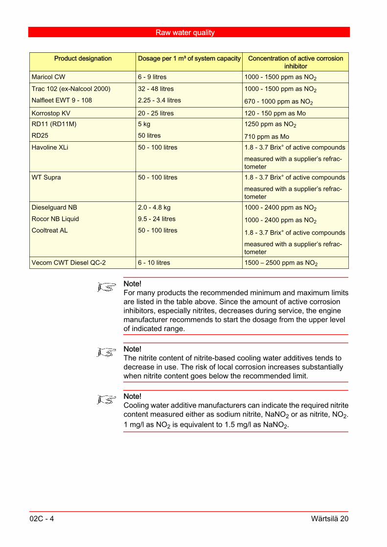
Product designation Dosage per 1 m³ of system capacity Concentration of active corrosioninhibitor
Maricol CW 6 - 9 litres 1000 - 1500 ppm as NO2
Trac 102 (ex-Nalcool 2000)
Nalfleet EWT 9 - 108
32 - 48 litres
2.25 - 3.4 litres
1000 - 1500 ppm as NO2
670 - 1000 ppm as NO2
Korrostop KV 20 - 25 litres 120 - 150 ppm as MoRD11 (RD11M)
RD25
5 kg
50 litres
1250 ppm as NO2
710 ppm as MoHavoline XLi 50 - 100 litres 1.8 - 3.7 Brix° of active compounds
measured with a supplier’s refrac‐tometer
WT Supra 50 - 100 litres 1.8 - 3.7 Brix° of active compounds
measured with a supplier’s refrac‐tometer
Dieselguard NB
Rocor NB Liquid
Cooltreat AL
2.0 - 4.8 kg
9.5 - 24 litres
50 - 100 litres
1000 - 2400 ppm as NO2
1000 - 2400 ppm as NO2
1.8 - 3.7 Brix° of active compounds
measured with a supplier’s refrac‐tometer
Vecom CWT Diesel QC-2 6 - 10 litres 1500 – 2500 ppm as NO2
Note!For many products the recommended minimum and maximum limitsare listed in the table above. Since the amount of active corrosioninhibitors, especially nitrites, decreases during service, the enginemanufacturer recommends to start the dosage from the upper levelof indicated range.
Note!The nitrite content of nitrite-based cooling water additives tends todecrease in use. The risk of local corrosion increases substantiallywhen nitrite content goes below the recommended limit.
Note!Cooling water additive manufacturers can indicate the required nitritecontent measured either as sodium nitrite, NaNO2 or as nitrite, NO2.1 mg/l as NO2 is equivalent to 1.5 mg/l as NaNO2.
Raw water quality
02C - 4 Wärtsilä 20

02C.4. Use of glycol V3
If a freezing risk exists, glycol needs to be added to cooling water.Since glycol alone does not protect the engine and cooling water sys‐tem against corrosion, an approved cooling water additive must alsobe used. All approved cooling water additives are compatible withglycol.Ready-to-use mixtures containing both glycol and corrosion inhibitorsare not permitted since the concentration of each component cannotbe individually optimized. Usually, if the inhibitor concentration is cor‐rect, the glycol concentration will be unnecessarily high. No reductionin the glycol concentration is possible without increasing the risk ofcorrosion.The amount of glycol in a closed cooling water systems should alwaysbe minimized since glycol adversely affects the heat transfer proper‐ties of water. Therefore it may be necessary to de-rate the engine ifglycol is used; see document DAAE062266 for more information.Two types of glycol are available: monopropylene glycol (MPG) andmonoethyleneglycol (MEG). So called industrial qualities of both gly‐col types can be used, but MPG is considered to be less harmful tothe environment.
Raw water quality
Wärtsilä 20 02C - 5

Raw water quality
02C - 6 Wärtsilä 20

03. Start, Stop and Operation V1
03.1. Start V1
Before starting the engine, check that the lubricating oil level is correct, the fuel system is in running order (correct preheating, correct
pressure, sufficient precirculation to heat the high pressure pump), both cooling water systems, LT- and HT-water circuit, are in
running order (correct pressures, circulating water preheated andprecirculated sufficiently to heat the engine),
the oil level in the governor and turbocharger is correct, the starting air pressure exceeds 7.5 bar, the starting air system is drained of condensate, the fuel and cooling water systems are properly vented from air, power supply to all control systems is OK. if the engine is not preheated it must be run 15 minutes before the
full load.All covers and protecting shields are to be mounted before startingthe engine. Covers should be removed occasionally only for meas‐urements and checks, and they must be immediately mounted again.
Note!Never leave the engine running when covers are removed.
03.1.1. Local start V5
1 Start the prelubricating oil pump to obtain a oil pressure of about 0.5bar. Normally, the prelubricating oil pump is running when the engineis stopped (switch in auto-mode). The prelubricating oil pump is au‐tomatically switched off when the engine reaches 300 RPM in runningmode.
2 Turn the crankshaft by two revolutions or run the engine on startingair for some revolutions keeping the stop lever in stop position andthe indicator valves open. This eliminates the risk of water locks andclose the indicator valves later.
3 Disengage the turning gear from the flywheel.
Start, Stop and Operation
Wärtsilä 20 03 - 1

4 Check that the stop lever is in work position. Open the starting airvalve, shut the blow-off valve when there is no more condensate.
5 Push the start button till the engine starts firing. If the engine does notstart after 2-3 seconds the reason should be checked.
6 A second start attempt is automatically blocked by a time relay untilthe engine is absolutely standing still.
7 After start, check that the pressure and temperature values are nor‐mal.
03.1.2. Remote and automatic start V2
If the engine has been out of operation for more than a week, it mustfirst be started manually, as mentioned in point 1
Note!Engines with automatic start must be tested once a week.
1 When starting the engine remotely, start the lubricating oil primingpump at first. Usually, the operation of the pump is indicated by asignal lamp. The engine can be started when the lube oil pressuregauge shows an oil pressure of about 0.5 bar.In automatically starting engines, the priming pump operates contin‐uously thus keeping the engine ready for start. Every second day,ensure that the pump is running.
2 Press the remote start button of the remotely controlled engine. Thesolenoid valve located on the engine is energized and allows startingair into the engine. Press the start button long enough (2-3 seconds)to make the engine start. The remote tachometer or a signal lampindicates that the engine is running. In some cases the remote controlstarts the priming pump. After the oil pressure increases to about 0.5bar, the engine starts automatically. Between each attempt to startthe engine via the external control system (if the first start attemptfails), ensure that the engine has stopped completely. This time gapis normally about 30 seconds but has to be checked/adjusted caseby case. The number of automatic starting attempts must be limitedin order to reserve some capacity of the starting air bottles.
3 When the engine reaches a predeterminated speed, an auxiliary relayenergized by the remoted tacho transmitter cuts off the starting circuitand the starting air solenoid valve closes. At the same time the currentto the priming pump is disconnected thus preventing the pump fromoperating when the engine is running. On certain installations the pri‐ming pump continues to operate at low engine speed to assist the
Start, Stop and Operation
03 - 2 Wärtsilä 20

engine driven lubricating oil pump to maintain the oil pressure. Aftera fixed time (10-30 seconds) the system for alarm, stop and speedremote control is automatically connected.
03.2. Stopping the engine V5
The engine can always be stopped manually (with the stop lever) in‐dependent of the remote control or automation system.
Note!When overhauling the engine, make absolutely sure that the ready/blocked switch is in "blocked" position and the priming pump is dis‐connected.
1 Idle the engine 1 minute before stopping.
2 Close the starting air shut-off valve located before the pressure reg‐ulating valve.
3 Push the STOP button or move the stop lever into STOP position.The time of slowing down offers a good opportunity to detect possibledisturbing sounds.
03.2.1. Stopping the engine for a lengthy time V1
1 Check that the indicator valves are closed. See chapter 12: Operationand maintenance of the indicator valve. It is also advisable to coverthe exhaust pipe opening to prevent water from entering the cylindersvia the exhaust manifold.
2 Fill the lubricating oil system on a stopped engine with oil every sec‐ond day by priming the engine. At the same time, turn the crankshaftinto a new position. This reduces the risk of corrosion on journals andbearings when the engine is exposed to vibrations.
3 Run the engine by the air starter. Ensure that the indicator valves areopen. start the engine once a week to check that everything is in order.
03.2.2. Remote stop V6
1 Engines with built-in circulating water pump: Idling more than 3-5 mi‐nutes before stopping is unnecessary and should be avoided.
Start, Stop and Operation
Wärtsilä 20 03 - 3

2 Press the remote control stop button. The shut-down solenoid, builton the governor, will then be energised for a fixed time and the controlracks of the injection pumps will move into the stop position. The timefor the solenoid to be energised is set at 20-50 seconds so that thesolenoid operates until the engine stops. During this time the enginecannot be restarted. After a predetermined time the shut-down sole‐noid will return to its initial position.
3 When the engine stops and the speed decreases below a certain limit,the system for alarm, stop and speed remote control will be discon‐nected and the signal lamp will indicate that the engine is shuttingdown. In engines equipped with automatic lubricating oil primingpumps, the pump will be started at the same time.
03.2.3. Automatic stop V5
When the shut-down solenoid is energized from the automatic shut-down system due to some disturbance, the engine will stop as in re‐mote stop. Before this, an alarm device will normally initiate an alarmsignal indicating the reason for the shut-down.When the engine stops because of overspeed, the electro-pneumaticoverspeed trip device may have tripped.
03.3. Normal operation supervision V2
If an alarm limit is reached and an alarm is activated, the engine sit‐uation is already serious. All necessary countermeasures must betaken to remove this emergency condition and return to normal op‐erating conditions. As the abnormal operating situation may causedamages to the engine, all efforts must be put into returning to thenormal operating situation instead of just waiting for an automatic shutdown of the engine.
03.3.1. Every second day or after every 50 runninghours V5
1 Read the values of thermometers, pressure gauges and the load ofthe generating set. Compare the values, with those at the corre‐sponding load in the Acceptance test records and curves.
Start, Stop and Operation
03 - 4 Wärtsilä 20

Guidance values are stated in Chapter 01: Main Data, Operating Dataand General Design. If the difference between exhaust gas temperatures of various
cylinders is larger than 70°C at loads higher than 25% the causeshould be established.
At loads higher than 80%, the charge air temperature should beas low as possible, but not so low that condensation occurs, seeFig 03-1. At loads lower than 25% it is favourable to have thecharge air temperature as high as possible.
2 Check the indicator for pressure drop over fuel filters, if installed.When the pressure drop over the filters increases, the pressure in thesystem decreases. Very low pressure (less than 0.5 bar) reduces theengine performance and may cause uneven load distribution betweenthe cylinders (risk of breakdown). Too high pressure drop may alsoresult in deformation of filter cartridges (risk of injection pump seiz‐ure).
3 Check the indicator for pressure drop over the lubricating oil automaticfilter. A too large pressure drop indicates clogged filter candles, whichresults in reduced oil filtration when the overflow valves are open(from a differential pressure of 2 bar upwards). Reduced oil filtrationresults in increased wear. Clean or change clogged filter candles.
4 Check the oil level in the oil sump/oil tank. Estimate the appearanceand consistence of the oil. The presence of water may be simply con‐trolled by dropping oil onto a hot surface (about 150°C). If the drops"frizzle", the oil contains water. Compensate for oil consumption byadding maximum 10% fresh oil at a time.
5 Check that the ventilation (de-aerating) of the engine circulating watersystem (the expansion tank) is working. Check that the leakage fromthe "tell-tale" drainage holes of the circulating water pumps is not ex‐cessive.
6 Check the quantity of leak-fuel from the drain pipes. .
7 Check that the drain pipes of the air coolers are open.
8 Check that the "tell-tale" drainage holes of the oil coolers and the cir‐culating water coolers are open.
9 Clean the compressor side of the turbocharger by injecting water. SeeChapter 15: Turbocharging and Air cooling.
10 Drain the fuel day tank of any water and sediments, and drain thestarting air receiver of water.
11 On a stopped generating set, prime the engine and turn the crankshaftinto a new position. This reduces the risk of crankshaft and bearingdamage due to vibrations.
Start, Stop and Operation
Wärtsilä 20 03 - 5
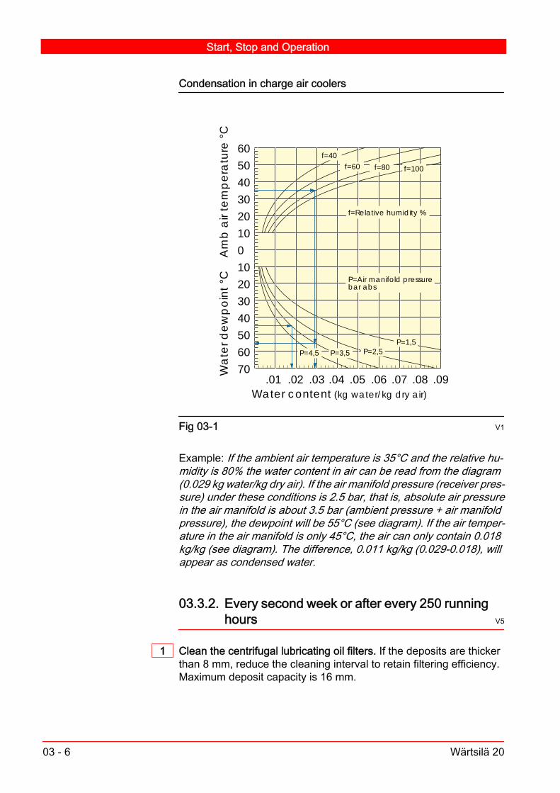
Condensation in charge air coolers
60
50
40
30
20
10
0
10
20
30
40
50
60
70.01 .02 .03 .04 .05 .06 .07 .08 .09
Water content
Wa
ter d
ew
po
int
°C
(kg water/kg dry air)
Am
b a
ir te
mp
era
ture
°C
P=Air manifold pressurebar abs
P=4,5 P=2,5P=3,5P=1,5
f=40f=60 f=80 f=100
f=Relative humidity %
Fig 03-1 V1
Example: If the ambient air temperature is 35°C and the relative hu‐midity is 80% the water content in air can be read from the diagram(0.029 kg water/kg dry air). If the air manifold pressure (receiver pres‐sure) under these conditions is 2.5 bar, that is, absolute air pressurein the air manifold is about 3.5 bar (ambient pressure + air manifoldpressure), the dewpoint will be 55°C (see diagram). If the air temper‐ature in the air manifold is only 45°C, the air can only contain 0.018kg/kg (see diagram). The difference, 0.011 kg/kg (0.029-0.018), willappear as condensed water.
03.3.2. Every second week or after every 250 runninghours V5
1 Clean the centrifugal lubricating oil filters. If the deposits are thickerthan 8 mm, reduce the cleaning interval to retain filtering efficiency.Maximum deposit capacity is 16 mm.
Start, Stop and Operation
03 - 6 Wärtsilä 20
2 Keep the injection pump racks clean (free from sticky deposits).Check that the parts of the fuel control shaft system move easily. Thismust be done on a stopped engine.
Note!There are hot surfaces inside the hot box, when the engine is warm.
3 Clean the turbine side of the turbocharger by injecting water. SeeChapter 15: Turbocharging and Air cooling.
03.3.3. Once a month or after every 500 running hours V7
1 Check the concentration of additives in the circulating water.
2 Check the cylinder pressures. At the same time, note the load of the engine. The position of the loadindicator or the injection pump racks offers an accurate measure ofthe engine load.
Note!Measuring the cylinder pressures without simultaneously noting theengine load is practically useless.
3 Check the function of the cooling system.
03.3.4. In connection with maintenance work V3
1 Record the following steps and the running hours in the engine log: lubricating oil sampling (record also operating time of oil). Lubri‐
cating oil analyses without a statement of operating times are oflimited value ("go/no-go" only).
lubricating oil changes. cleaning of centrifugal lubricating oil filters. change of lubricating and fuel oil filter cartridges. change of parts in connection with maintenance according to
Chapter 04: Maintenance Schedule.
03.3.5. General maintenance V1
1 There is no automatic supervision or control arrangement that canreplace an experienced engineer's observations.LOOK at and LISTEN to the engine!
Start, Stop and Operation
Wärtsilä 20 03 - 7

2 Strong gas blow-by past the pistons is one of the most dangerousthings that can occur in a diesel engine. If gas blow-by is suspected(e.g. because of a sudden increase of the lubricating oil consumption)check the crankcase pressure. If the pressure exceeds 20 mm H2O(100% load), check the crankcase venting system and cylinder tight‐ness, if in order, check the function of the radial turbocharger.
3 Operation at loads below 20 % of rated output should be limited tomaximum 100 hours continuously when operating on heavy fuel byloading the engine above 70 % of rated load for one hour before con‐tinuing the low load operation or shutting down the engine. Continu‐ous operation on marine diesel fuel at loads below 10 % of rated out‐put should be limited to maximum 100 hours by loading the engineby more than 70 % of rated output for one hour before continuing thelow load operation or shutting down the engine.Idling (i.e. main engine declutched, generator set disconnected)should be limited as much as possible.
03.4. Start after a prolonged stop (more than 8 h)V4
1 Check: lubricating oil level circulating water level in the expansion tank raw water supply to heat exchangers fuel oil level in the day tank (it is a troublesome and time consum‐
ing job to vent the fuel system if the feed pump has sucked in air!) starting air pressure that the control shaft system and the injection pump racks move
freely, otherwise there is a risk of overspeed.2 Observe all points in Chapter 03: Local start. Point 2 becomes more
important the longer the engine has been stopped.3 Vent fuel and lubricating oil filters.
4 After starting, check that pressure and temperature reach the normallevels.
Start, Stop and Operation
03 - 8 Wärtsilä 20

03.5. Start after overhaul V5
1 Check that the connection between the speed governor and injectionpumps is set correctly (especially the injection pump rack position)and does not jam, and that all connections are properly locked andthe injection pump racks move freely in the pumps.
2 Activate manually the solenoid for the overspeed trip device. Checkthat all injection pump racks move to a value less than 5 mm.
3 If the injection pumps, camshaft or its driving mechanism have beentouched, check the injection timing. If the camshaft or its drivingmechanism have been touched, check the valve timing of one cylin‐der, at least.
4 Check the cooling water system for leakage, especially: the lower part of the cylinder liners the oil cooler the charge air cooler
5 Check/adjust the valve clearances. Guidance values, see chapter06.
6 Vent the fuel oil system if it was opened.
7 Start the priming pump. Vent the lubricating oil filters. Check that lu‐bricating oil appears from all bearings and lubricating nozzles, fromthe piston cooling oil outlet and from the valve mechanism. Check thatthere is no leakage from the pipe connections inside or outside theengine.
Note!Observe that the crankshaft has to be turned in order to get oil throughall connecting rods and valve yokes.
8 Rags or tools left in the crankcase, untensioned or unlocked screwsor nuts (those which are to be locked), worn-out self-locking nuts,MAY CAUSE total breakdown.Well cleaned oil spaces (oil sump and camshaft spaces) save the oilpump and oil filter.
9 See the instructions in chapter 03., sections 03.1 and 03.4 whenstarting.
03.6. Supervising operation after overhaul V2
1 At the first start, listen carefully for possible jarring sounds.
Start, Stop and Operation
Wärtsilä 20 03 - 9

Caution!If anything unusual is noticed, stop the engine immediately.
2 Let the engine idle at normal speed for five minutes.
3 Check the condition of the stopped engine.a ) Stop the engine.
b ) Check the temperature of the main and big end bearings.
c ) Check the temperature of all other bearings which have beenopened.
d ) If everything is in order, restart the engine.
4 Check the engine for leakage of gas, water, fuel or lubricating oil.a ) Check the fuel lines, injection pumps and injection valves.
Note!Observe if the oil leakage from the pipes increases.
5 Check the condition of the running engine.a ) Check:
Pressure and temperature Automatic alarm and stop devices Pressure drop over the fuel filter and lubricating oil filter Oil level in the oil sump/oil tank Condition of the oil Ventilation of the engine cooling water system Quantity of leak fuel Inspection ports in the coolers Content of additives in the cooling water Cylinder pressures Crankcase pressure.
b ) Listen for jarring sounds.
c ) Vent the filters.
Start, Stop and Operation
03 - 10 Wärtsilä 20

03.7. Running-in V4
1 After piston overhaul, follow programme A as closely as possible. Thepiston rings have slid into new positions and need time to bed in. Ifthe programme cannot be followed, do not load the engine fully untilit has run for at least 4 hours.
2 After changing the below, follow programme B as closely as possi‐ble.: piston rings pistons or cylinder liners honing of cylinder liners
Running-in programme
1 2 3 4 5 6 7 h
0
10
20
30
40
50
60
70
80
90
100
Engine load %
Operating hours
A After piston overhaulB After change of piston rings, pistons or cylinder liners,
after honing cylinder liners
Stop. Check big end bearing temperatures
End of running-in programme. Engine may be put on normal mode
1
2 2
1
2
Fig 03-2 V1
Caution!If the programme cannot be followed, do not load the engine fully untilit has run for at least 10 hours.
Caution!Avoid running-in at a continuous low load.
The important thing is to vary the load several times. The ring groovewill tilt differently at each load stage, and consequently the line ofcontact between the ring and cylinder will change.
Start, Stop and Operation
Wärtsilä 20 03 - 11

The running-in may be performed either on distillate or heavy fuel,using the normal lubricating oil specified for the engine.
Start, Stop and Operation
03 - 12 Wärtsilä 20

04. Maintenance Schedule V3
The maintenance in general is necessary for the engine according tothe operating conditions especially when attached with generating setor similar attachments. Because of the difficulty of anticipating thevarious operating conditions that may be encountered in the field, theperiods stated in the schedule should be used for guidance purposesonly. They must not however be exceeded during the warranty period.If, at a shorter interval than recommended, observations or inspec‐tions indicate that it is necessary to perform a maintenance procedureor to replace a component, such work should not be delayed. Whileusing diesel or intermediate fuels of comparatively good quality asfuel, it may be possible to extend the stated maintenance intervalsconsiderably depending on the load of the engine. See also the chap‐ter for the turbocharger and the governor and the instructions in chap‐ter Start, Stop and Operation. For Risk Reduction see chapter 00: Risk Reduction. For Environmental Hazards see chapter 00: Hazardous
substances Before any steps are taken, read the corresponding item in this
Manual carefully. At all maintenance work, observe the utmost cleanliness and
order. Before dismantling, check that all systems concerned are drained
or the pressure is released. After dismantling, immediately coverholes for lubricating oil, fuel oil and air with plugs.
When exchanging a worn-out or damaged part provided with anidentification mark stating cylinder or bearing number, mark thenew part with the same number on the same spot. Every exchangeshould be entered in the engine log and the reason should beclearly stated.
Always renew all gaskets , sealing rings and O-rings atmaintenance work.
After reassembling, check that all screws and nuts are tightenedand locked, if necessary.
Warning!During any form of maintenance, make absolutely sure that the au‐tomatic start and the priming pump are disconnected. Make also surethat the starting air shut-off valve located before the main startingvalve is closed. Otherwise it might cause engine personal injury and/or damage.
Maintenance Schedule
Wärtsilä 20 04 - 1

Warning!During any form of maintenance, make absolutely sure that the gearbox is not engaged and the generator breaker is secured to avoid anyengine rotation.
Warning!Accidental turning of engine may cause personal injury and/or enginedamage.
04.1. How to select application and fuel quality V2
There are two different types of applications defined: Average load is above 75 % of nominal engine output. Average load is below 75 % of nominal engine output.Three types of fuel are defined: HFO 1 Heavy fuel oil of normal quality. HFO 2 Heavy fuel oil of below normal standard quality. DO Diesel oil or light fuel oil (LFO).
Fuel characteristics, maximum limitsHFO 1 HFO 2
Sulphur % mass 1.5 1.5 - 4.5Ash % mass 0.05 0.05 - 0.15Vanadium mg/kg 100 100 - 600Sodium mg/kg 50 50Sodium, before engine mg/kg 30 30Aluminium + silicon mg/kg 30 30 - 80Aluminium + silicon, bef.eng.
mg/kg 15 15
Conradson Carbon resi‐due
% mass 15 15 - 22
Asphaltenes % mass 8 8 - 14CCAI 850 850 - 870
Note!If any of specified fuel properties exceed HFO 1 maximum value thefuel should be classified as HFO 2.
Maintenance Schedule
04 - 2 Wärtsilä 20

04.2. Every second day V5
Every second day, irrespective of the engine being in operation or notAutomatic prelubrica‐tion
Check operation. 03.1.2
18.7Crankshaft Marine engine: In a stopped engine, turn the crankshaft into a new
position.
04.3. Once a week V1
Once a week irrespective of the engine being in operation or notStart process Test start (if the engine on stand-by). 03.1
04.4. Interval: 50 operating hours V12
Interval: 50 operating hoursAir cooler Check draining of air cooler.
Check that the draining pipe is open, check for leak‐age.
15.2.1
03.3.1
Cooling system Check water level in cooling system.
Check the water level in the expansion tank(s) and/or the static pressure in the engine cooling circuits.
19.2, 19.7
Connecting rod Check tightening of the connecting rod screws.
Check the tightening of the connecting rod screwsafter the first 50 operating hours on a new engine andafter overhaul (those screws that have been opened).
11.4.4
07
Fuel and lubricating oilfilters
Check pressure drop indicators.
Change filter cartridges if high pressure drop is indi‐cated.
17.2
03.3.1
23.1Gauges and indicators Take readings.
Read and record (use form No. WV98V089) all tem‐perature and pressure gauges, and also the load ofthe engine.
03.3.1
Governor, actuator Check oil level in governor.
Check oil level, and look for leaks.
See manufacturers instructions.
Injection and fuel sys‐tem
Check leak fuel quantity.
Check the amount of leak fuel from the injectionpumps and injection nozzles.
03.3.1
17
Maintenance Schedule
Wärtsilä 20 04 - 3

Interval: 50 operating hoursInjection pipes Check tightening of injection pipe connections.
Check the tightening of injection pipe connections ona hot engine after the first 50 operating hours on anew engine and, after overhaul (those connectionsthat have been opened).
16.2
07.1
Lubricating oil sump Check oil level in sump.
Check oil level with a dip stick, compensate for con‐sumption.
18.1
02.2.1
Main bearings Check tightening of main bearing screws.
Check the tightening of main bearing screws after thefirst 50 operating hours on a new engine and afteroverhaul (those screws that have been opened).
10.4
07.1
Turbocharger Water cleaning of compressor.
Clean the compressor by injecting water.
15.1.4
Check the turbine side V-clamp ring tightening onTPS chargers.
If specified, after the first 50 operating hours on a newengine and, after overhaul.
See manufacturer's instructions
Check fastening bolts at feet, tighten housing boltsand piping joints.
Once after commissioning or overhaul; then every4000 hrs. See the turbocharger makers manual.
Valve mechanism Check valve clearances.
Check the valve clearances after 50 hours running innew and overhauled engines. Check tightening ofrocker arm screws and valve/yoke adjusting screwnuts.
12.2.5
06.1
07.1.3
Multiduct Check tightening of the multiduct screws.
Check the tightening of the multiduct screws after thefirst 50 operating hours on a new engine and, afteroverhaul (those screws that have been opened). Theengine should be at normal operating temperature.
07.1
04.5. Interval: 100 operating hours V7
Interval: 100 operating hoursTurbocharger Water cleaning of turbine.
Clean the turbine by injecting water; adjusted acc. to operation.
15.1.2
Maintenance Schedule
04 - 4 Wärtsilä 20
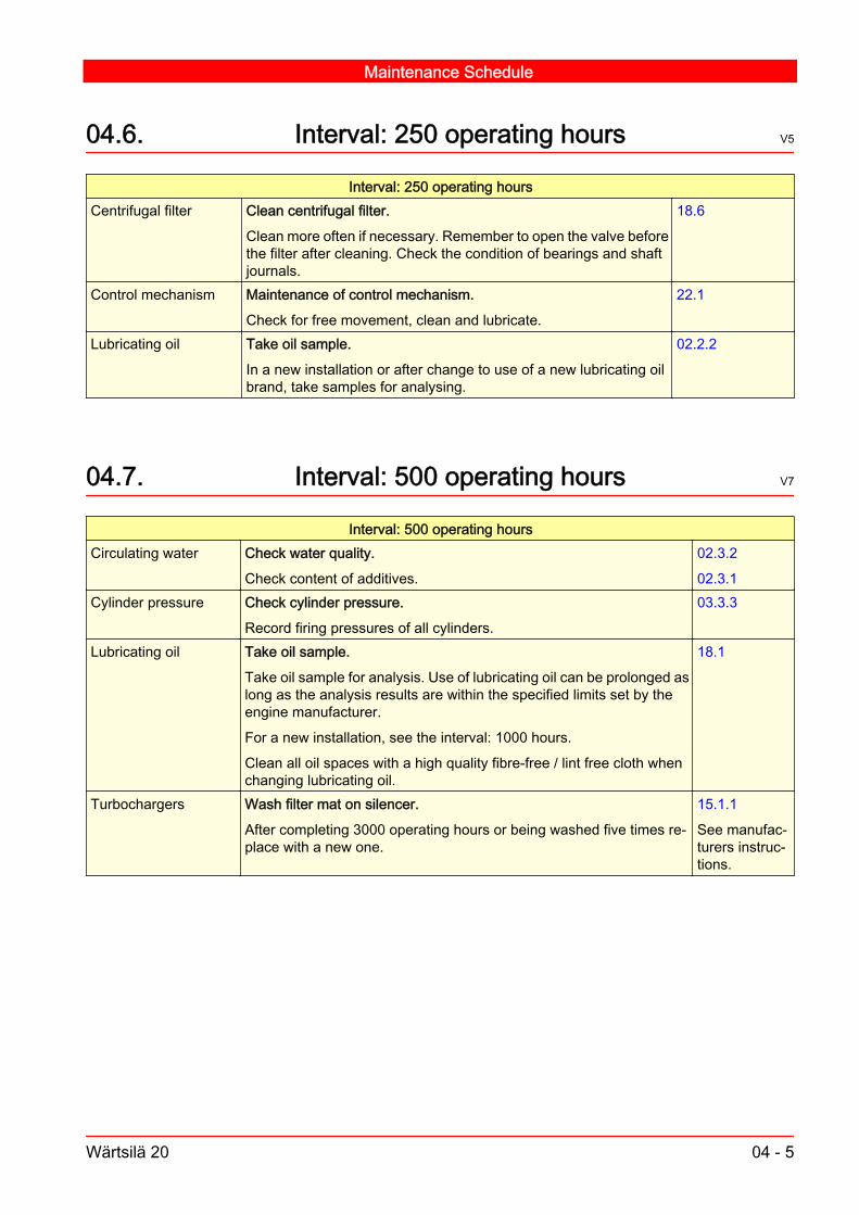
04.6. Interval: 250 operating hours V5
Interval: 250 operating hoursCentrifugal filter Clean centrifugal filter.
Clean more often if necessary. Remember to open the valve beforethe filter after cleaning. Check the condition of bearings and shaftjournals.
18.6
Control mechanism Maintenance of control mechanism.
Check for free movement, clean and lubricate.
22.1
Lubricating oil Take oil sample.
In a new installation or after change to use of a new lubricating oilbrand, take samples for analysing.
02.2.2
04.7. Interval: 500 operating hours V7
Interval: 500 operating hoursCirculating water Check water quality.
Check content of additives.
02.3.2
02.3.1Cylinder pressure Check cylinder pressure.
Record firing pressures of all cylinders.
03.3.3
Lubricating oil Take oil sample.
Take oil sample for analysis. Use of lubricating oil can be prolonged aslong as the analysis results are within the specified limits set by theengine manufacturer.
For a new installation, see the interval: 1000 hours.
Clean all oil spaces with a high quality fibre-free / lint free cloth whenchanging lubricating oil.
18.1
Turbochargers Wash filter mat on silencer.
After completing 3000 operating hours or being washed five times re‐place with a new one.
15.1.1
See manufac‐turers instruc‐tions.
Maintenance Schedule
Wärtsilä 20 04 - 5

04.8. Interval: 1000 operating hours V9
Interval: 1000 operating hoursAutomation Functional check of automation.
Check function of the alarm and automatic stop devices. 23.3.2
01.2Fuel filter Replace fuel oil filter cartridges.
Clean the wire gauze and filter housing. Replace the filter cartridg‐es. (The cartridges are to be replaced when the pressure differenceindicator shows too high pressure drop).
17
17.2
Lubricating oil Change lubricating oil.
Change oil in a new installation (wet sump installations). Take sam‐ples for analysing. Use of lubricating oil can be prolonged, in stepsof 500 operating hours, as long as the analysis results are withinthe specified limits set by the oil supplier or the engine manufac‐turer.
Change oil in an installation (wet sump installations) that is not pu‐rifying regularly the lubricating oil, independently of oil analysis re‐sult.
Clean all oil spaces with a high quality fibre-free / lint free cloth whenchanging lubricating oil.
18.1
02.2.2
Valves Check of valve condition.
Check valve clearances.
Check cylinder tightness (valves, piston rings) with a pneumatictest. Check that the inlet and exhaust valves move freely in theirguides. This should preferably be done when the engine has beenout of operation for a couple of hours.
12.2.5
06.1
12A
Maintenance Schedule
04 - 6 Wärtsilä 20

04.9. Interval: 2000 operating hours V8
Interval: 2000 operating hoursCharge air cooler Check water side of charge air cooler.
The first time check and possible cleaning of the waterside . If ingood condition and deposits unsignificant: future intervals 4000running hours.
15.2.1
Measuring instruments Checking of gauges.
Check pressure and temperature gauges. Replace faulty ones.23.1
Governor Change oil in governor.
Change lubricating oil.
02.2.3
Injection valves Inspect injection valves.
Test the opening pressure. Dismantle and clean nozzles. Check theeffective needle lift. Check the springs. Replace the O-rings. .
16.4.2
Overspeed trip device Check function of overspeed trip.
Check function and tripping speed
22.4
04.10. Interval: 4000 operating hours V8
Interval: 4000 operating hoursAir cooler Clean the charge air cooler.
Clean the air and water side of the charge air cooler and pressuretest it. Look carefully for corrosion.
15.2.1
Automation Check connectors and cables.
Check mounting and connection. Make a visual check of all cablesand replace these cables that are damaged.
23.1
Camshaft and valvemechanism
Visually inspect contact faces of camshaft.
Check the contact faces of the cams and tappet rollers. Check valveyoke and adjusting screw nut and that the rollers rotate. Rotate theengine with the turning gear.
14
Control mechanism Check control mechanism.
Check for wear in all connecting links between the governor and allinjection pumps.
22.1
Flexible coupling If specified check alignment, use form WV98V041. Check conditionof coupling.
See manufactur‐ers instructions.
Crankshaft Check crankshaft alignment.
Check alignment, use form No. WV98V036. Alignment check hasto be performed on a warm engine.
11.1.2
Resilient mounts Inspect buffer clearance, reset if necessary. Inspection to be madeat least once a year.
Maintenance Schedule
Wärtsilä 20 04 - 7
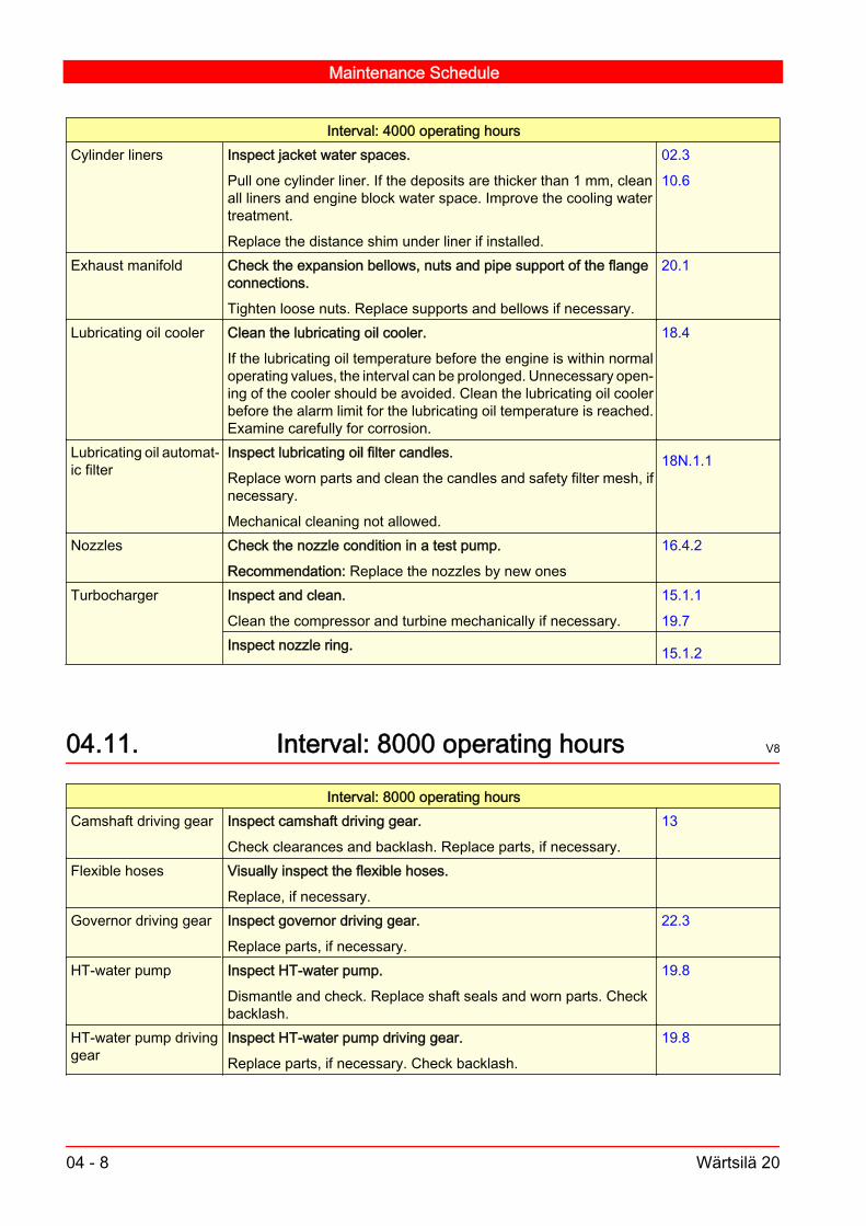
Interval: 4000 operating hoursCylinder liners Inspect jacket water spaces.
Pull one cylinder liner. If the deposits are thicker than 1 mm, cleanall liners and engine block water space. Improve the cooling watertreatment.
Replace the distance shim under liner if installed.
02.3
10.6
Exhaust manifold Check the expansion bellows, nuts and pipe support of the flangeconnections.
Tighten loose nuts. Replace supports and bellows if necessary.
20.1
Lubricating oil cooler Clean the lubricating oil cooler.
If the lubricating oil temperature before the engine is within normaloperating values, the interval can be prolonged. Unnecessary open‐ing of the cooler should be avoided. Clean the lubricating oil coolerbefore the alarm limit for the lubricating oil temperature is reached.Examine carefully for corrosion.
18.4
Lubricating oil automat‐ic filter
Inspect lubricating oil filter candles.
Replace worn parts and clean the candles and safety filter mesh, ifnecessary.
Mechanical cleaning not allowed.
18N.1.1
Nozzles Check the nozzle condition in a test pump.
Recommendation: Replace the nozzles by new ones
16.4.2
Turbocharger Inspect and clean.
Clean the compressor and turbine mechanically if necessary.
15.1.1
19.7Inspect nozzle ring. 15.1.2
04.11. Interval: 8000 operating hours V8
Interval: 8000 operating hoursCamshaft driving gear Inspect camshaft driving gear.
Check clearances and backlash. Replace parts, if necessary.
13
Flexible hoses Visually inspect the flexible hoses.
Replace, if necessary.
Governor driving gear Inspect governor driving gear.
Replace parts, if necessary.
22.3
HT-water pump Inspect HT-water pump.
Dismantle and check. Replace shaft seals and worn parts. Checkbacklash.
19.8
HT-water pump drivinggear
Inspect HT-water pump driving gear.
Replace parts, if necessary. Check backlash.
19.8
Maintenance Schedule
04 - 8 Wärtsilä 20

Interval: 8000 operating hoursHT-water thermostaticvalve
Clean and inspect HT-water thermostatic valve.
Clean and check the thermostatic element, valve cone-casing andsealings.
19.9
LT-water thermostaticvalve
Clean and inspect LT-water thermostatic valve.
Clean and check the thermostatic element cone-casing and replacesealings. Check the function of the valve.
19.9
LT-water pump Inspect LT-water pump.
Dismantle and check. Replace shaft seals and worn parts. Checkbacklash.
19.8
LT-water pump drivinggear
Inspect LT-water pump driving gear.
Replace parts, if necessary. Check backlash.
19.8
Lubricating oil pump Inspect the lubricating oil pump.
Dismantle and check. Replace worn parts. Check backlash.
18.2
Oil pump driving gear Inspect oil pump driving gear.
Replace parts, if necessary. Check backlash.
18.2
Oil thermostatic valve Clean and inspect oil thermostatic valve.
Clean and check the thermostatic element, valve cone-casing andsealings.
18.5
Prelubricating oil pump Inspect the prelubricating oil pump.
Replace shaft seals and worn parts.
18.7
Electrical motor Electrical motor for prelubricating oil pump.
Replace roller bearings on electrical motor or latest after three (3)years in use.
Lubricating oil automat‐ic filter
Replace lubricating oil filter candles.
Drain the filter housing. Clean the wire gauze. Replace the filtercandles.
Conduct visual inspection of all filter candles once a year. Replacethe filter candles after latest 2 years in service or if Δp alarm occurs.
18N.1
Fuel system Check and adjust fuel system.
Check the settings of the fuel system. Check for possible leakage.Replace parts, if necessary.
17
Starting/smoke fuellimiter
Check function of starting/smoke fuel limiter. 22
23.1Air starter General overhaul of air starter motor.
Conduct starter maintenance along with general engine mainte‐nance or latest after 3 years. Replace bearings, solenoid valve andworn parts.
21.1
See manufactur‐ers instructions.
Maintenance Schedule
Wärtsilä 20 04 - 9

04.12. Overhaul interval V1
FuelOverhaul interval
Average load > 75 % Average load < 75 %HFO 2 8000 10000HFO 1 12000 14000
DO 16000 20 000
04.13. Interval: (8000 - 20000) See table 04.12. V7
Interval: (8000 - 20000) See table aboveConnecting rod Replace big end bearings.
Replace big end bearings. Inspect mating face and surface of ser‐rations. Measure the big end bore, use form 2011V001.
11.4.2
Inspect small end bearings
Replace if necessary, use form 2011V007.
11.4.3, 06.2
Crankshaft Check thrust bearing clearance.
Check axial clearance
10.5.3
Cylinder heads Overhaul of cylinder head.
Dismantle and clean the underside, inlet and exhaust valves andports. Pull out the exhaust gas seat rings, inspect cooling spacesand clean, replace the O-ring(s). If necessary, grind the valves andEX / IN seat rings (often lapping by hand is enough). Inspect thevalve rotators.
Replace the O-rings in the valve guides. Use the Cylinder HeadOverhaul Report measurement record 2012V015.
12
Cylinder liners Inspect the cylinder liners.
Measure the bore using form No. 2010V002, replace liner if wearlimits are exceeded. Hone the liners. Renew the antipolishing ring.
10.6
Inspect all cylinder liners water side and replace O-rings.
Pull all cylinder liners. If the deposits are thicker than 1 mm, cleanall liners and the engine block water space. Replace the O-rings inthe bottom part by new ones at every overhaul.
19.7
10.6
Injection pumps Overhaul of injection pumps.
Clean and inspect injection pumps, replace worn parts. Replace allseal rings and constant pressure valve. Check the erosion plugs,replace if necessary.
16.2.7
Pistons Inspect the piston.
Dismantle one composite piston for inspection of mating surfacesbetween piston skirt and piston crown. Inspect and clean oil spaces.Repeat the procedure with other pistons if necessary.
11.4.3
Maintenance Schedule
04 - 10 Wärtsilä 20

Interval: (8000 - 20000) See table abovePiston, piston rings Inspect pistons and piston rings.
Pull, inspect and clean. Check the height of the ring grooves. Checkthe retainer rings of the gudgeon pins. Replace complete set of pis‐ton rings. Note the running-in program.
11.4.2
Main bearings Inspect the bearing shells of one main bearing.
Replace all bearing shells, if necessary.
10.4.2
Turbocharger
TPS-chargers
Inspect the bearings of radial type charger.
Replace bearings if necessary.
15.1.1
See manufactur‐ers instructions.
Valve mechanism Check valve mechanism bearings.
Check tappets and rocker arms. Replace valve tappet roller bearingbush, if specified.
14.3.2
06.2
04.14. Interval: 16000 operating hours V5
Interval: 16000 operating hoursFuel feed pump Inspect fuel feed pump.
General overhaul and replace shaft seals and gaskets.
Governor drive Check the governor drive bearing.
Check governor driving shaft bearing clearance in situ.
22.3.1
06.2Vibration damper Dismantle and check. 11.1
See manufactur‐ers instructions.
Viscous vibrationdamper
Take oil sample from vibration damper.
Take oil sample for analysing.
11.1
See manufactur‐ers instructions.
Camshaft Inspect camshaft bearings.
Replace if necessary.
14.3.2
06.2Intermediate gears andbearings
Inspect gear teeth and measure backlash and axial clearance. Re‐place bearings at least every 32. 000 hrs.
13
06.2Governor Governor general overhaul at an authorized workshop latest after 5
years in use.See manufactur‐ers instructions.
Check the function and adjustments of the governor.
Replace worn parts.
22.3
Maintenance Schedule
Wärtsilä 20 04 - 11

04.15. Interval: 24000 operating hours V8
Interval: 24000 operating hoursConnecting rod Replace connecting rod screws.
Replace connecting rod screws at the latest every 24000 operatinghrs. with new ones.
11.4.4
07
Crankshaft Inspect crankshaft.
Inspect the crankshaft bearing surfaces. Measure the crankpin di‐ameter and ovality.
06.2
Engine fastening bolts Check tightening of engine fastening bolts.
Replace if necessary.
07.3
Overspeed trip device
Elektro-pneumatic
General overhaul of overspeed trip device.
Check function and tripping speed.
22.4
22.4.2Turbocharger Replace turbocharger bearings. 15.1.1
See manufactur‐ers instructions.
Automation and controlsystem
Replace vibration dampers (rubber elements).
Replace the rubber elements for components such as connectionboxes, control modules, connection rails and main cabinet. The vi‐bration damper should be replaced latest every fourth (4) year.
23.3.1
04.16. Interval: 24000 operating hours or after 5years V6
Interval: 24000 operating hours or after 5 yearsValve mechanism Replace rocker arm screws, yoke and adjusting screw nuts. 14.1Injection valve yoke Injection valve yoke tension screws.
Replace screws.
12
Exhaust gas piping Exhaust gas piping support, plates, nuts and screws.
Replace supports, nuts and screws.
20.1
Control mechanism Replace support bearing bushes and V-rings on fuel control shaft. 22.1
Maintenance Schedule
04 - 12 Wärtsilä 20

04.17. Interval: 48000 operating hours V1
Interval: 48000 operating hoursTurbocharger Replace rotor. 15.1.1
See manufactur‐ers instructions.
Maintenance Schedule
Wärtsilä 20 04 - 13

Maintenance Schedule
04 - 14 Wärtsilä 20

05. Maintenance tools V1
Maintenance of the engine requires the use of some special toolsdeveloped in the course of engine design. Some of these tools aredelivered with the engine, others are available from the Wärtsilä'sservice stations.The tools required for a particular installation varies depending on theapplication. The standard tool sets have been composed to meet thebasic requirements.Before starting a maintenance work, check that all necessary spareparts, consumables and maintenance tools are available. The re‐quired maintenance tools are stated in the maintenance instructions.Tools available from Wärtsilä are listed in the Spare Parts Catalogue.Tools delivered with the engine are listed in the installation specificdelivery list.Regarding maintenance tools for the governor and the turbocharger,refer to the enclosed governor and turbocharger documentation.
05.1. About Spare Parts Catalogue V1
The Spare Parts Catalogue presents a comprehensive selection oftools for the Wärtsilä engines. Each tool is specified by a code and adescriptive name. In order to facilitate the choice of tools for a specificservice operation, the tools are grouped according to the engine partthey are intended for. The tools for servicing a certain part are shownin a picture, where each tool is marked with its code. They are alsolisted in a table with tool codes and names.
Note!Some of the tools listed in the Spare Parts Catalogue are only appli‐cable for certain cylinder numbers and/or certain engine mountingequipment.
05.2. Ordering maintenance tools V2
To order maintenance tools or spare parts:
Maintenance tools
Wärtsilä 20 05 - 1

1 Find the required tools or parts in the Spare Parts Catalogue. Notedown the specifications (part number and name) from the Spare PartsCatalogue along with other ordering information, or fill in the Inquiry/Order List. See the table below for required ordering information. Theengine type, engine specification and engine number are found onthe engine name plate.Table 05-1 Information required when ordering maintenance tools
Required information ExampleEngine type Wärtsilä 9L20Specification number 173176Engine number PAAE035380Tool number 832 004Name of part Lifting tool for cylinder headQuantity 1Name of consignee Engineer A. Clipper
M/S BrigitteC/O SeaforwardingSea Port, Hull
Purchaser Shipowner AtlantaHead Square,Birmingham E.C.
Method of forwarding Express air line
2 Send the order to the Wärtsilä Service Office address printed on theInquiry/Order List, or directly to Wärtsilä. Addresses and telephonenumbers are printed on the title page of this manual. All commercialterms are stated in the Inquiry/Order List.
Note!All orders placed by telephone should be confirmed by email or letter.
When ordering special equipment or tools not included in the SpareParts Catalogue or Instruction Manual, please state the manufactur‐er's type designation and serial number. If the data is not available,describe the tool as clearly as possible and enclose a picture.
Maintenance tools
05 - 2 Wärtsilä 20

06. Adjustments, Clearances and WearLimits V2
06.1. Adjustments V8
Valve timingThe valve timing is fixed and cannot be changed individually, cylinderby cylinder.
Valve timingEX
HAU
ST
VALV
E
INLE
T VA
LVE
1
2
3
4
5
1. Inlet valve opens. 2. TDC. 3. Exhaust valve closes. 4. Exhaust valveopens. 5. BDC inlet valve closes.
Fig 06-1 200601 V3
Adjustments, Clearances and Wear Limits
Wärtsilä 20 06 - 1
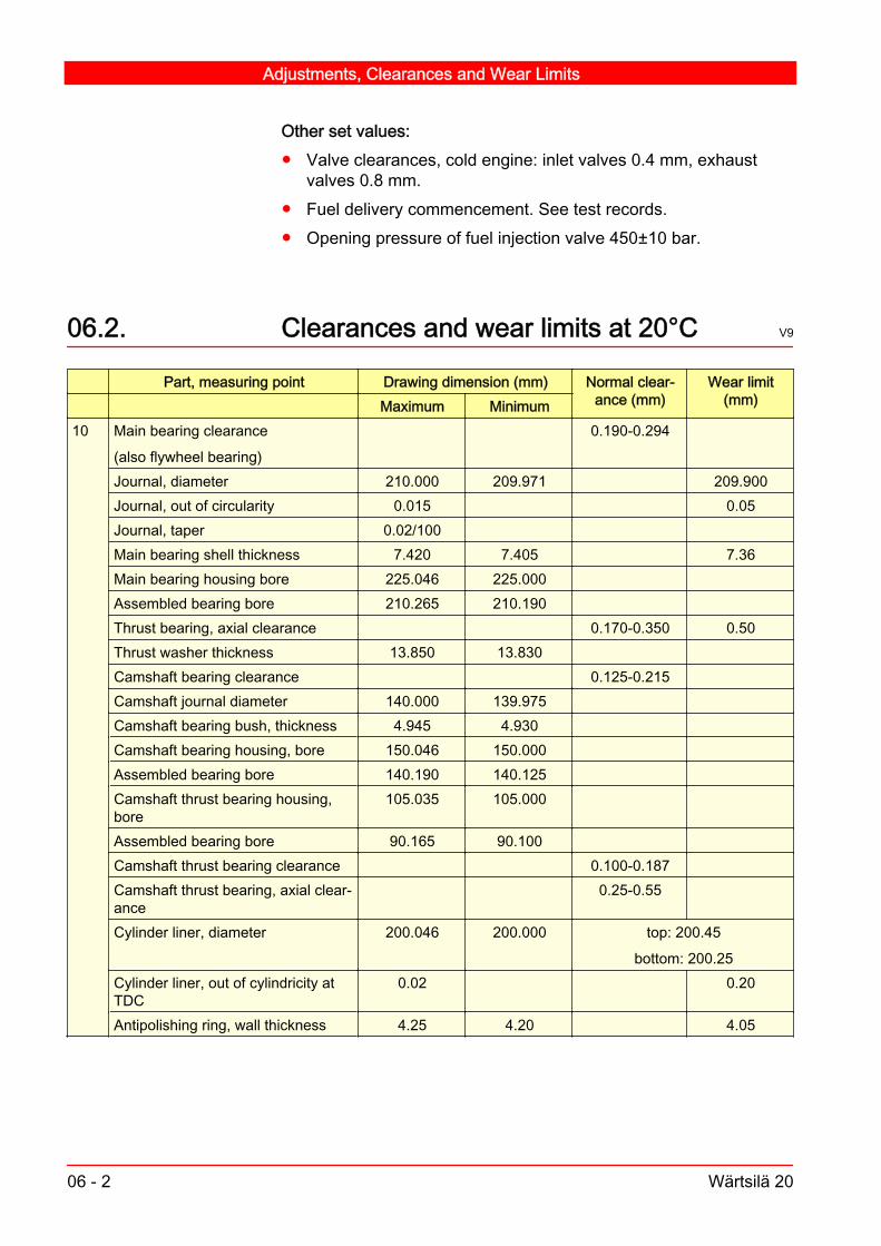
Other set values: Valve clearances, cold engine: inlet valves 0.4 mm, exhaust
valves 0.8 mm. Fuel delivery commencement. See test records. Opening pressure of fuel injection valve 450±10 bar.
06.2. Clearances and wear limits at 20°C V9
Part, measuring point Drawing dimension (mm) Normal clear‐ance (mm)
Wear limit(mm) Maximum Minimum
10 Main bearing clearance
(also flywheel bearing)
0.190-0.294
Journal, diameter 210.000 209.971 209.900Journal, out of circularity 0.015 0.05Journal, taper 0.02/100Main bearing shell thickness 7.420 7.405 7.36Main bearing housing bore 225.046 225.000Assembled bearing bore 210.265 210.190Thrust bearing, axial clearance 0.170-0.350 0.50Thrust washer thickness 13.850 13.830Camshaft bearing clearance 0.125-0.215Camshaft journal diameter 140.000 139.975Camshaft bearing bush, thickness 4.945 4.930Camshaft bearing housing, bore 150.046 150.000Assembled bearing bore 140.190 140.125Camshaft thrust bearing housing,bore
105.035 105.000
Assembled bearing bore 90.165 90.100Camshaft thrust bearing clearance 0.100-0.187Camshaft thrust bearing, axial clear‐ance
0.25-0.55
Cylinder liner, diameter 200.046 200.000 top: 200.45
bottom: 200.25Cylinder liner, out of cylindricity atTDC
0.02 0.20
Antipolishing ring, wall thickness 4.25 4.20 4.05
Adjustments, Clearances and Wear Limits
06 - 2 Wärtsilä 20

Part, measuring point Drawing dimension (mm) Normal clear‐ance (mm)
Wear limit(mm) Maximum Minimum
11 Big end bearing clearance 0.145-0.230Crankshaft, axial clearance 0.170-0.350Crank pin, diameter 180.000 179.975 179.900Crank pin, out of circularity 0.015 0.05Crank pin, taper 0.03/100Big end bearing shell thickness 4.950 4.935 4.90Big end bore, ovality 190.029 190.000 0.12Assembled bearing bore 180.205 180.145Gudgeon pin bearing clearance 0.050-0.112Gudgeon pin diameter 90.000 89.990Small end bore 105.022 105.000Assembled bearing bore 90.120 90.068Connecting rod axial clearance in pis‐ton
0.2-0.6
Small end bearing bush, thickness 7.475 7.460Piston gudgeon pin clearance 0.04-0.07Piston gudgeon pin diameter 90.060 90.040Piston ring height clearance:Compression ring 1Compression ring 2Oil scraper ring
0.10-0.1450.06-0.1050.04-0.075
0.40.350.35
Piston ring groove height:Groove IGroove IIGroove III
6.125.086.05
6.095.056.03
6.405.356.30
Piston crown M18 screw length 66.5 66.3 67.111B11C
Balancing shaft 4L20 and 5L20
Intermediate gear axial clearance
0.10-0.20
Balancing shaft intermediate gear,bearing clearance
0.06-0.15
Axial clearance 0.10-0.20Backlash balancing shaft intermedi‐ate gear/crankshaft gear
0.10-0.30
Backlash balancing shaft intermedi‐ate gear/balancing shaft gear
0.30-0.50
Backlash balancing shaft gear/bal‐ancing shaft gear
0.21-0.43
Drive shaft, axial clearance 0.15-0.40Drive shaft, bearing clearance 0.090-0.169Balancing shaft bearing clearance 0.090-0.169
Adjustments, Clearances and Wear Limits
Wärtsilä 20 06 - 3

Part, measuring point Drawing dimension (mm) Normal clear‐ance (mm)
Wear limit(mm) Maximum Minimum
12 Valve guide diameter assembled 14.088 14.034Valve stem diameter 14.000 13.982 13.95Valve stem clearance 0.04-0.10 0.20Valve seat deviation relative guide(maximum value)
0.10
Inlet valve seat bore in cylinder head 78.019 78.000Exhaust valve seat bore in cylinderheadouter boreinner bore
78.01967.019
78.00067.000
13 Camshaft drive intermediate gear
bearing clearance
axial clearance
0.100-0.187
0.25-0.54
0.22
0.60
Bearing diameter 90.165 90.100Bearing journal diameter 90.000 89.978Camshaft driving gear backlash:Crankshaft gear wheel/large inter‐mediate gear wheel
0.10-0.50
Small intermediate gear wheel/cam‐shaft gear wheel
0.20-0.37
Base tangent length:- crankshaft gear wheel, assembled 130.505 130.449- large intermediate gear wheel 130.283 130.227- small intermediate gear wheel 84.228 84.172- camshaft gear wheel 140.331 140.275
14 Valve tappet, diameter 54.970 54.940Guide diameter 55.030 55.000Diameter clearance 0.09-0.15Tappet roller bore diameter 22.021 22.000Tappet pin diameter 21.993 21.980Clearance roller pin 0.007-0.041Rocker arm bearing diameter 50.064 50.025Bearing journal diameter 50.000 49.984Bearing clearance 0.025-0.080 0.20Yoke pin diameter 19.935 19.922Yoke bore diameter 20.021 20.000Diameter clearance 0.065-0.099 0.15
16 Nozzle needle lift 0.45 0.5517 Fuel feed pump backlash: Driving
gear wheel to crankshaft gear wheel0.24-0.47
Adjustments, Clearances and Wear Limits
06 - 4 Wärtsilä 20

Part, measuring point Drawing dimension (mm) Normal clear‐ance (mm)
Wear limit(mm) Maximum Minimum
18 Lubricating oil pump diameter of shaft 49.92 49.895Bush hole diameter, assembled 50.045 49.99Bearing clearance 0.080-0.165 0.20Axial clearance: 4, 5 and 6L20 0.120-0.230Axial clearance: 8 and 9L20 0.130-0.220 Backlash for pump gear wheels 0.432-0.736Backlash for pump gear wheel/inter‐mediate gear wheel
0.15-0.48
Intermediate gear, bearing clearance 0.06-0.15Intermediate gear, axial clearance 0.10-0.20Backlash for intermediate gearwheel/crankshaft gear wheel
0.10-0.30
Base tangent length over 2 teeth 43.37 43.25819 Water pump backlash for driving gear 0.26-0.55
Backlash for sea water pump drivinggear/intermediate gear wheel
0.10-0.40
Backlash for sea water pump inter‐mediate gear/crankshaft gear wheel
0.20-0.50
Base tangent length over 4 teeth 53.643 53.56321 Airstarter pinion wheel backlash 0.89-1.15 22 Driving shaft for governor 22.0 21.987
Bearing for driving shaft 22.058 22.026Bearing clearance 0.026-0.071Axial clearance 0.10-0.50Backlash for driving gear 0.07-0.25Control shaft 20.000 19.967Control shaft bearing 20.162 20.110Clearance 0.110-0.195
Adjustments, Clearances and Wear Limits
Wärtsilä 20 06 - 5

Adjustments, Clearances and Wear Limits
06 - 6 Wärtsilä 20

07. Tightening Torques and Instructions forScrew Connections V2
07.1. Tightening torques for screws and nuts V9
Note!Tightening torques for hydraulically tightened connections are pre‐sented in their own section.
In the following sections from A on, the position numbers in the tablesrefer to the corresponding figures that represent the main compo‐nents of the engine.Threads and contact faces of nuts and screw heads should be oiledwith lubricating oil unless otherwise stated. Locking fluids are used incertain cases.
Note!Do not use Molykote or similar low friction lubricants for any screwsor nuts due to risk of overtensioning.
Warning!Always tighten to the torque specified in the tables. A loose screwconnection may cause serious damages or human injury.
1 Nm = 0.102 kpm
Tightening Torques and Instructions for Screw Connections
Wärtsilä 20 07 - 1

Tightening torques
G
H A
B
C
DE
I
KJ
F
Fig 07-1 200774 V1
We recommend the use of torque measuring tools also when tight‐ening other screws and nuts. The following torques apply to screwsof the strength class 8.8 when oiled with lubricating oil or treated withLoctite.
Screw dimension Width across flats of hexa‐gon screws (mm)
Key width of hexagon sockethead screws (mm)
Torque
(Nm) (kpm)M5 8,5 4 5,4 0,55M6 10 5 9.5 0.95M8 13 6 23 2.3
M10 17 8 45 4.6M12 19 10 80 8.1M16 24 14 190 19.3M20 30 17 370 37.5M24 36 19 640 65
Tightening Torques and Instructions for Screw Connections
07 - 2 Wärtsilä 20

07.1.1. A: Crankshaft and flywheel V8
1
3
2
Fig 07-2 200756 V2
Pos. Screw connection Torque (Nm)1. Crankshaft flange screws (fitted bolts).
Lubricate the contact faces of the screws and holeswith Molykote G-n Plus, the threads with oil.
300
Use the torque multiplier X-4. 91Crankshaft flange screws (hexagon socket screws).Lubricate the washers with Molykote G-n Plus, thethreads with oil.
600±20
Use the torque multiplier X-4. 1822. Screws for counterweight, M24 (two counterweights
per crank) Lubricate with engine oil. 480±20
Use torque multiplier X-4. 1453. Screws for the gear rim halves. Apply Loctite 242 on
threads, see section 07.2. 49
Tightening Torques and Instructions for Screw Connections
Wärtsilä 20 07 - 3

07.1.2. B: Camshaft and intermediate gear V6
1
2
Fig 07-3 200771 V1
Pos. Screw connection Torque (Nm)1. Screws for housing, apply Loctite 245 252. Screws for intermediate gear, 5xM20. Lubricate the
threads and the screw head with oil.530±15
Tightening Torques and Instructions for Screw Connections
07 - 4 Wärtsilä 20

07.1.3. C: Valve mechanism and multihousing V8
1
26
7
3 4
5
Fig 07-4 200790 V1
Posi‐tion
Screw connection Torque (Nm)
1. Screws for valve tappet guide block and injectionpump.
110±5
2. Rocker arm console, fastening screws. 200±53. Fastening screws, cylinder head/multiduct. 804. Fastening screws, multiduct/exhaust manifold. 805. Multiduct fastening screws with distance sleeves. 806. Locking nut for valve clearance adjusting screw. 1007. Locking nut for valve yoke adjusting screw. 60
Tightening Torques and Instructions for Screw Connections
Wärtsilä 20 07 - 5

07.1.4. D: Injection pump V7
3 0 4 00
1
2
3
4
5
7
6
BOSCHPFR 1 CY 180V
Fig 07-5 200772 V1
Pos. Screw connection Torque (Nm)
Bosch
PFR 1 CY 180V1. Side screw 14±12. Grub screw 14±13. Erosion plug
Apply Loctite 242 on threads, see section 07.2
85±5
4. Injection pump element fastening screws. 33±2Note! Tighten the screws crosswise in steps
Lubricate threads with Molykote G-n plus
0..10..20..33
5. Screw for fuel rack indicator 3,5±0,56. Screws for pressure valve 33±2
Note! Tighten the screws crosswise in steps
Lubricate threads with Molykote G-n plus
0..10..20..33
7. Vent screw 22±2
Tightening Torques and Instructions for Screw Connections
07 - 6 Wärtsilä 20

07.1.5. E: Fuel injection valve V7
1
2
3
4
5
6
7
Fig 07-6 200779 V1
Position Screw connection Torque (Nm)1. Injection nozzle cap nut.
Lubricate threads and contact face with Molykote G-n Plus.
270±10
2. Screws for protecting sleeve. 253. Injection valve fastening nuts, see section 16.4.4. 50±34. Connection piece to nozzle holder, lubricate the connecting piece with oil. 65±55. Injection pipe cap nuts to injection pump, lubricate the nuts with oil. 55±56. Nut for pressure adjustment. 100±107. Guide screw
Apply Loctite 241 on threads, see Chapter 07: Use of locking fluid.
10+5
Note!Injection valves of type 1 have an adjusting screw placed at the sideof the valve, while injection valves of type 2 and 3 have an adjustingscrew at top of the valve.
Tightening Torques and Instructions for Screw Connections
Wärtsilä 20 07 - 7

07.1.6. F: Piston V5
Tightening the piston screw (One screw)
60º
1
1. Piston with 1 screw
Fig 07-7 V1
Piston with 1 screw Posi‐tion
Screw connection Torque (Nm)
Angle (°)1. Screw for piston (M18x1.5):
New screw with old or new crown 1. Lubricate threads and contact surfaces with Moly‐kote G-N Plus
2. Tighten the screw to 45 Nm3. Tighten the screw further 90°4. Loosen the screw 5. Tighten the screw again to 45 Nm6. Tighten the screw further 60°+5°7. Check with tightening torque, the screw may not turnfurther 130 Nm
Note! When changing piston crown, renew the screw. Old screw with old crown
1. Lubricate threads and contact surfaces with Moly‐kote G-N Plus
2. Tighten the screw to 45 Nm3. Tighten the screw further 60°+5°4. Check with tightening torque, the screw may not turnfurther 130 Nm
Tightening Torques and Instructions for Screw Connections
07 - 8 Wärtsilä 20

Tightening the piston screw (Two screws)
1
75º
65º
1. Piston with 2 screws
Fig 07-8 V2
Piston with 2 screws Posi‐tion
Screw connection Torque (Nm)
Angle (°)1. Screws for piston crown (M10):
New screws with old or new crown 1. Lubricate the threads and screw head with engineoil
2. Tighten screws to 10±1 Nm3. Tighten the screws a further 75°+5°4. Loosen the screws 5. Tighten the screws again to 10±1 Nm6. Tighten the screws further 65°+5°7. Check with tightening torque, the screw may not turn 50 NmNote! When changing piston crown, renew the screw.
Old screws with old crown 1. Lubricate the threads and screw head with engineoil
2. Tighten the screws to 10±1 Nm3. Tighten the screws further 65°+5°4. Check with tightening torque, the screw may not turnfurther 50 Nm
Tightening Torques and Instructions for Screw Connections
Wärtsilä 20 07 - 9

07.1.7. G: Engine driven pumps V6
A
B
3
4
8
2 67
5
1
C
A
9
A.Oil pump, B. Water pump, C. Fuel oil pump
Fig 07-9 200770 V4
Tightening Torques and Instructions for Screw Connections
07 - 10 Wärtsilä 20

Pos. Screw connection Torque (Nm)1. Fastening screws for lubricating oil pump driving
gear (connection with four Inbus Plus fasteningscrews). The screws are treated with locking com‐pound and can be used only once. Replace thescrews with new, treated ones. Only Driloc 201 orDriloc 211 should be used.
75±5
2. Fastening screw for impeller of water pump.
Apply Loctite 243 on threads , see section 07.2.
85±5
3. Fastening screws for water pump driving gear (con‐nection with three Inbus Plus fastening screws.).The screws are treated with locking compound andcan be used only once. Replace the screws withnew, treated ones. Only Driloc 201 or Driloc 211should be used.
35±3
4. Fastening screws for fuel oil pump driving gear(connection with three Inbus Plus fasteningscrews.). The screws are treated with locking com‐pound and can be used only once. Replace thescrews with new, treated ones. Only Driloc 201 orDriloc 211 should be used.
35±3
5. Fastening screw for bearing housing cap.
Apply Loctite 243 on threads , see section 07.2.
9.5±1
6. Fastening screw for pump body. 257. Fastening nut for coupling.
Apply Loctite 243 on threads , see section 07.2.
27±3
8. Fastening screw for valve cover. 259. Fastening torque for oil pump cover 50
Tightening Torques and Instructions for Screw Connections
Wärtsilä 20 07 - 11

G: Engine driven pumps
A B
1
2
3
A. Prelubricating oil pump Kracht, B. Sea water pump
Fig 07-10 200785 V2
Pos. Screw connection Torque (Nm)1. Fastenings screws for valve cover. 492. Fastenings screws for shaft of intermediate gear. 503. Fastening screw for impeller of sea water pump.
Apply Loctite 243 on threads , see section 07.2.
85±5
Tightening Torques and Instructions for Screw Connections
07 - 12 Wärtsilä 20

07.1.8. H: Free end of crankshaft V7
1
Fig 07-11 V1
Posi‐tion
Screw connection Torque (Nm)
1. Screws (M24) for pump driving gear at free endof crankshaft. Lubricate screws with engine oil. 960±20
Use the torque multiplier X-4. 290
Tightening Torques and Instructions for Screw Connections
Wärtsilä 20 07 - 13

07.1.9. I: Side screws for main bearings and screwsfor engine foot V6
1
2
1
1
2
1
Fig 07-12 200777 V1
Pos. Screw connection Torque (Nm)1. Fastening screws for engine foot. 670±50
Use the torque multiplier X-4. 2052. a) Pretightening of main bearing side screws, apply
Molykote G-n Plus on contact face and engine oilon screw threads.
365
b) Tightening to full torque of main bearing sidescrews.
990±50
Use the torque multiplier X-4. 300
Tightening Torques and Instructions for Screw Connections
07 - 14 Wärtsilä 20

07.1.10. J : Intermediate gear for balancing shafts V5
1
Fig 07-13 V1
Pos. Screw connection Torque (Nm)1. Screw, M10x100 8.8, for shaft. 501. Screw, M10x100 10.9, for shaft. 67
07.2. Use of locking fluid V1
When using locking fluid (Loctite), clean parts carefully in a degreas‐ing fluid and let dry completely before applying locking fluid.
Tightening Torques and Instructions for Screw Connections
Wärtsilä 20 07 - 15

07.3. Hydraulically tightened connections V2
07.3.1. Pressures for hydraulically tightenedconnections V4
Hydraulically tightened connections
2
4 4
1
3
A
VIEW A
Fig 07-14 V1
Note!Tighten the nuts in two steps according to the table below. .
Pos. Screw connec‐tion
Torques(Nm)
Max. hydraulic pressure (bar)
Tighten‐ing ofstuds
1st stepTightening
2nd stepTightening Loosening
1. Main bearingnuts, M36 x 2 100±10 300 700 720
2. Connecting rodnuts, M30 x 2 20±5 300 550 570
3. Cylinder headnuts, M36 x 4 100±10 300 600 620
4. Camshaft nuts,M42 x 2
Tightenby hand 300 560 580
Tightening Torques and Instructions for Screw Connections
07 - 16 Wärtsilä 20

Caution!The screws will be overloaded if the maximum hydraulic pressure isexceeded.
If it is impossible to turn the nuts, when the maximum hydraulic pres‐sure is reached: check for corroded threads; check tool condition andmanometer error.
07.3.2. Maintenance of hydraulic tool set V2
The hydraulic tool set should be stored in a suitable place and corro‐sion protected. The set should be regularly checked and worn ordamaged parts replaced. Special attention should be made on fol‐lowing components. Pressure gauge: Regularly calibration checked. Hydraulic couplings and hoses: Condition check. Hydraulic pump: Condition check. Hydraulic cylinder o-ring: Wear and condition check.
Note!If the hydraulic cylinder o-ring has been exposed outside the cylinderthe oil has to be removed from the cylinder before the cylinder withthe o-ring can be re-installed. To return the o-ring with the oil in thecylinder will only damage the o-ring.
07.3.2.1. Filling, venting and control of the high pressurehydraulic tool set V2
The hydraulic tool set consists of a high pressure hand pump withintegrated oil container, hoses fitted with quick-couplings and non-return valves, cylinders and a pressure gauge mounted on the handpump but not connected to the pressure side of the pump.The components are coupled in series the pressure gauge being thelast component thus securing that every cylinder is fed with the correctpressure.
Tightening Torques and Instructions for Screw Connections
Wärtsilä 20 07 - 17

The non-return valves in the hoses are integrated with the quick-cou‐plings and are opened by the pins located in the centre of the maleand female parts. If these pins get worn the coupling must be replacedbecause of the risk of blocking. In the high pressure hydraulic tool set it is recommended to use a
special hydraulic oil or in any case an oil with a viscosity of about2°E at 20°C.
During the filling of the container of the high pressure pump it isrecommendable to couple the set according to scheme B, Fig07-15. Before filling, open the release valve (2) and empty thecylinders (4) by pressing piston and cylinder together. After that,the container can be filled through the filling plug (1).
After filling, vent the system by pressing in, with a finger, the centrepin of the female part of the last quick-coupling the coupling beingdisconnected from the pressure gauge. Keep on pumping untilairfree oil emerges from the coupling.
Check the pressure gauge of the hydraulic tool set regularly. Forthis purpose a comparison pressure gauge can be delivered. Thispressure gauge can be connected to the plug hole (7) the outlethose of the pump being connected direct to the pressure gauges.If, it is necessary to operate with the couplings not completely in‐tact, it is advisable to open the air vent screw to assure that thepassage is open to all cylinders before tightening the connection.
Hydraulic cylinder
Hydraulic oil
A B 2 57
61 3
4
1. Filling plug, 2. Release valve, 3. Pressure hose, 4. Cylinders, 5. Outlet hose,6. Pressure gauge, 7. Plug hole.
Fig 07-15 200761 V1
Note!Always connect the last end of the outlet hoses to the pressure gauge.
Tightening Torques and Instructions for Screw Connections
07 - 18 Wärtsilä 20

07.3.3. Dismantling hydraulically tightened screwconnections V2
1 Attach distance sleeves and hydraulic cylinders according to Fig07-15 A. Screw on cylinders by hand.
2 Connect the hoses to the pump and cylinders according to Fig07-15 B. Open the release valve (2) and screw cylinders in clockwisedirection to expel possible oil.
3 Screw the cylinders in counter-clockwise direction about 3/4 a revo‐lution (270°), M42x3 (camshaft) about 21/2 revolution (900°) other‐wise the nut is locked by the cylinder and impossible to loosen.
4 Close the release valve and pump pressure to the stated value.
5 Screw the nut in counter-clockwise direction about half a turn with thepin.
6 Open the release valve and remove the hydraulic tool set.
7 Screw of the nuts by hand.
07.3.4. Reassembling hydraulically tightened screwconnections V2
1 Screw on nuts and attach distance sleeves. Screw on cylinders byhand.
2 Connect the hoses to the pump and cylinders. Check that the releasevalve is open and screw the cylinders in clockwise direction to expelpossible oil.
3 Close the release valve and pump pressure to the stated value.
4 Screw the nuts in clockwise direction until close contact to face. Usethe pin intended for this purpose and tighten the nut as much as pos‐sible without breaking the pin. Keep pressure constant at the statedvalue.
5 Open the release valve and remove the hydraulic tool set. To ensure that the nut will be properly tightened, the pressure can beraised in two steps. Pump the pressure to 300 bar and screw the nutin a clockwise direction until in close contact with the face. Increasethe pressure further to the stated pressure, and screw the nut until inclose contact with the face again. This time the nut should move justa limited angle but approximately the same angle for all nuts of thesame kind.
Tightening Torques and Instructions for Screw Connections
Wärtsilä 20 07 - 19

Note!Before the engine is started, ensure that all screw connections thathave been opened are properly tightened and locked, if necessary.
Tightening Torques and Instructions for Screw Connections
07 - 20 Wärtsilä 20
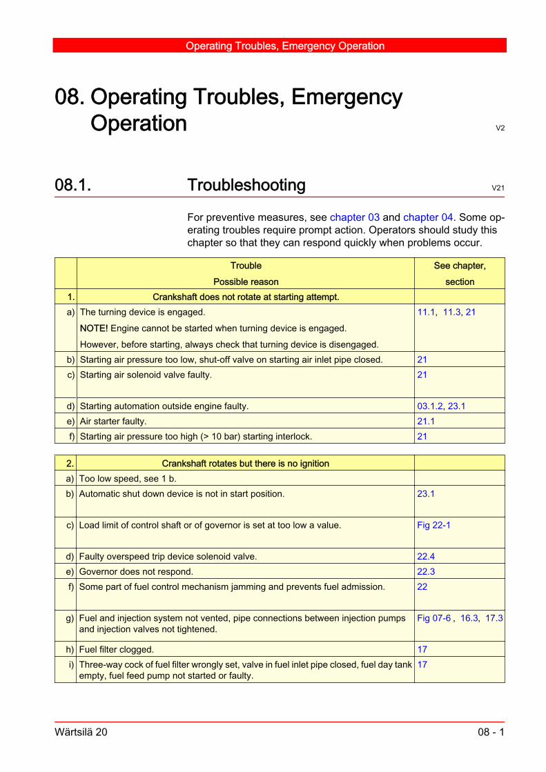
08. Operating Troubles, EmergencyOperation V2
08.1. Troubleshooting V21
For preventive measures, see chapter 03 and chapter 04. Some op‐erating troubles require prompt action. Operators should study thischapter so that they can respond quickly when problems occur.
Trouble
Possible reason
See chapter,
section1. Crankshaft does not rotate at starting attempt.a) The turning device is engaged.
NOTE! Engine cannot be started when turning device is engaged.
However, before starting, always check that turning device is disengaged.
11.1, 11.3, 21
b) Starting air pressure too low, shut-off valve on starting air inlet pipe closed. 21c) Starting air solenoid valve faulty. 21
d) Starting automation outside engine faulty. 03.1.2, 23.1e) Air starter faulty. 21.1f) Starting air pressure too high (> 10 bar) starting interlock. 21
2. Crankshaft rotates but there is no ignitiona) Too low speed, see 1 b.b) Automatic shut down device is not in start position. 23.1
c) Load limit of control shaft or of governor is set at too low a value. Fig 22-1
d) Faulty overspeed trip device solenoid valve. 22.4e) Governor does not respond. 22.3f) Some part of fuel control mechanism jamming and prevents fuel admission. 22
g) Fuel and injection system not vented, pipe connections between injection pumps
and injection valves not tightened.Fig 07-6 , 16.3, 17.3
h) Fuel filter clogged. 17i) Three-way cock of fuel filter wrongly set, valve in fuel inlet pipe closed, fuel day tank
empty, fuel feed pump not started or faulty.17
Operating Troubles, Emergency Operation
Wärtsilä 20 08 - 1

2. Crankshaft rotates but there is no ignitionj) Very low air and engine temperatures (preheat circulating water!) in connection with
fuel of low ignition quality.02.1
k) Fuel insufficiently pre-heated or precirculated Fig 02-2, 02.1.7l) Very low compression pressure. Inlet or exhaust valve jamming in open position.
"Negative" valve clearance (strong blowing noise).
06.1
06.1
m) Faulty governor. 22
3. Engine fires irregularly, some cylinders do not fire at alla) Jamming valves, inadequate fuel supply, too low temperatures, see 2 f, g, h, j, k, l,
4 d.b) Injection pump control rack wrongly adjusted. 22.2.1c) Injection pump faulty (plunger or tappet sticking; delivery valve spring broken, de‐
livery valve sticking).16.2
d) Injection valve faulty; nozzle holes clogged. 16.4e) Piston rings badly worn or damaged; too low compression pressure. 11.4.3f) In special cases, in engines which have to idle continuously for longer periods (sev‐
eral hours), for some reason, it is advisable to adjust the rack positions carefully(reduce rack position on those cylinders having the highest exhaust gas tempera‐tures, increase on those cylinders which are not firing). This adjustment should bedone in small steps and the difference between rack positions of the cylinders shouldnot exceed 1 mm.
4. Engine speed not stablea) Governor adjustment faulty (normally too low compensation). 22b) Some part of fuel control mechanism jamming and prevents fuel admission. 22
c) Fuel feed pressure too low. 01.2d) Water in pre-heated fuel (vapour lock in injection pumps). 02.1.2e) External loading automation is faulty (for example: Controllable pitch propeller). 23.1
5. Knocks or detonations occur in engine
(if reason cannot be found immediately, stop the engine)a) Big end bearing clearance too large (loose screws). 06.2, 07.3b) Valve spring or injection pump tappet spring broken. 12.3c) Inlet or exhaust valve jamming when open. 12.3d) Too large valve clearances. 06.1
12.2.5e) One or more cylinders badly overloaded, see 3 b.f) Injection pump/valve tappet (multihousing) guide block loose. Fig 07-4 16.1
Operating Troubles, Emergency Operation
08 - 2 Wärtsilä 20

5. Knocks or detonations occur in engine
(if reason cannot be found immediately, stop the engine)g) Initial phase of piston seizure.h) Insufficient preheating of engine in combination with fuel of low ignition quality. Fig 02-2j) Fuel injection timing wrong. 13.1.2
6. Dark exhaust gasesa) Late injection (wrongly set camshaft drive). 13.1.2b) See 3 b, c, d.c) Engine overloaded (check the positions of the fuel injection pump racks).d) Unsufficient charge air pressure:
air intake clogged.
turbocharger compressor dirty.
charge air cooler clogged on air side.
turbocharger turbine badly fouled.
NOTE! Engines starting on heavy fuel may smoke if left idling.
Test Records
04.7
04.4
04.9
04.5
7. Engine exhaust gases blue-whitish or grey whitisha) Excessive lubricating oil consumption due to:
gas blow-by past piston rings.
worn or broken oil scraper rings or worn cylinder liners.
compression rings.
compression rings turned upside-down.
ring scuffing (burning marks on sliding surfaces).
03.3.5, 06.2
b) Blue-white exhaust gases may occasionally occur when engine has been idling fora lengthy time or at low ambient temperature, or for a short time after starting.
c) Grey white exhaust gases due to water leakage from turbocharger or multiduct.
8. Exhaust gas temperature of all cylinders abnormally higha) Engine badly overloaded (check injection pump rack positions) Test Recordsb) See point 6 d.c) Charge air temperature too high:
charge air cooler clogged on water side or dirty on air side.
water temperature to air cooler too high, water quantity unsufficient.
engine room temperature abnormally high.
01.2, 15.2, 01.2,01.3
d) Excessive deposits in cylinder head inlet or exhaust ports. 12.2e) Exhaust pipe pressure after the turbine is high.
Operating Troubles, Emergency Operation
Wärtsilä 20 08 - 3

9. Exhaust gas temperature of one cylinder above normal Test Recordsa) Faulty exhaust gas thermometer/sensor. 23.1b) Exhaust valve:
jamming when open.
"negative" valve clearance.
sealing surface blown by (burned).
12.3
c) Faulty injection valve: opening pressure much too low.
nozzle needle sticking open.
broken spring.
nozzle cracked.
16.4
d) Late injection. 13.1.2e) Fuel supply insufficient (filter clogged). 01.2f) Injection pump faulty, fuel rack sticking in high load position. 16.2
10. Exhaust gas temperature of one cylinder below normala) Faulty exhaust gas thermometer/sensor. 23.1b) See 2 f, h, 3 b, c, d.
.c) Leaky injection pipe or pipe fittings. Fig 07-6d) When idling, see 3 f.
11. Exhaust gas temperatures very unequala) See 9 a, c, e.b) Too low fuel feed pressure: too small flow through injection pumps.
(see 2 h, i). May cause great load differences between cylinders although injectionpump rack positions are the same.
Warning! Causes high thermal overload in individual cylinders.
01.2
c) See points 2 l, 3 b, c, d, e.d) When idling, see point 3 f.e) Exhaust pipe or turbine nozzle ring partly clogged. 15.1.2
12. Lubricating oil pressure lacking or too low 01.2a) Check the pressure difference indicator. 23.1b) Faulty pressure gauge, gauge pipe clogged. 23.1c) Lubricating oil level in oil sump too low. 01.1, 18d) Lubricating oil pressure control valve out of adjustment or jamming. 18.3e) Three-way cock of lubricating oil filter wrongly set.
Operating Troubles, Emergency Operation
08 - 4 Wärtsilä 20

12. Lubricating oil pressure lacking or too low 01.2f) Leakage in lubricating oil suction pipe connections. 18
g) Lubricating oil badly diluted with diesel oil, viscosity of oil too low.
02B
02B.1
h) Lubricating oil pipes inside engine loose or broken. 18
13. Too high lubricating oil pressurea) See 12 b and d.
14. Too high lubricating oil temperature 01.2a) Faulty thermometer. 23.1b) Insufficient cooling water flow through oil cooler (faulty pump, air in system, valve
closed), very high raw water temperature.19
c) Oil cooler clogged, deposits on tubes. 18.4d) Faulty thermostat valve. 18.5, 19.9
15. Abnormally high cooling water outlet temperature, difference between cooling waterinlet and outlet temperatures too large
01.2
a) One of thermometers faulty. 23.1b) Circulating water cooler clogged, deposits on tubes. 19c) Insufficient flow of cooling water through engine (circulating water pump faulty), air
in system, valves closed.19.8
d) Thermostat valve faulty. 19.9
16. Water in lubricating oil 03.3.1a) Leaky oil cooler. 18.4b) Leakage at cylinder liner O-rings (always pressure test when cooling water system
has been drained or cylinder liners have been dismantled).10.6
c) Faulty lubricating oil separator. See separator instruction book.d) Leakage at LT cooling connection between engine block and free end cover. 19
17. Water in charge air receiver (escapes through drain pipe in air cooler housing) 15.2.1a) Leaky air cooler. 15.2b) Condensation (too low charge air cooling water temperature). Fig 03-1c) Leakage from multiduct. 20.1
18. Engine looses speed at constant or increased loada) Engine overloaded, a further increase of fuel supply is prevented by the mechanical
load limiter.Fig 22-1
b) See 2 c, f, g, h, i.c) See 4 c, d, 5 g, 19 d.
Operating Troubles, Emergency Operation
Wärtsilä 20 08 - 5

19. Engine stopsa) Shortage of fuel, see 2 h, i.b) Overspeed trip device has tripped. 22.4c) Automatic stop device has tripped. 23.1d) Faulty governor or governor drive. 22.3
20. Engine does not stop although stop lever is set in stop position or remote stop signalis given
a) Injection pump control rack wrongly set, see 3 b.
Trip the overspeed trip device manually. If the engine does not stop immediately,block fuel supply as near to the engine as possible.
Before restarting the engine, the fault must be located and corrected.
Great risk of overspeed.b) Faulty stop automation. Stop by means of stop lever. 23.1c) The engine is driven by generator or propeller or by another engine connected to
same reduction gear.
21. Engine overspeeds and does not stop although overspeed trip device tripsa) Injection pump control rack wrongly set, see 3 b. Load the engine, if possible.
Block fuel supply.
16.2
b) An overspeeding engine is hard to stop. Therefore, regularly check the adjustmentof the control mechanism (the injection pump rack positions).
1) The stop lever being in stop position or the overspeed trip device being trippedand the speed governor at maximum fuel admission.
2) The stop lever and the overspeed trip being in work position and the speed gov‐ernor in stop position.
This control should always be done when the control mechanism or the injectionpumps have been touched.
22.1
08.2. Emergency operation V2
08.2.1. Operation with defective air cooler V7
If the water tubes of an air cooler are defective, the cooling water mayenter the cylinders. If water or water mist flows out of the drain pipeat the bottom of the cooler housing, check whether it is cooling wateror condensation. If condensation, reduce cooling (see Fig 03-1). Ifraw water, stop the engine as soon as possible and fit a spare cooler.If no spare cooler is available, the following can be done as an emer‐gency solution:
Operating Troubles, Emergency Operation
08 - 6 Wärtsilä 20

1 Dismantle the cooler for repair and blank off the opening in the chargeair cooler housing. Connect the cooling water supply direct to the lu‐bricating oil cooler. Repair the cooler, for example, by plugging theleaking tubes.
Note!This will influence on the water flow to the lube oil cooler and the lubeoil temperature will increase.
2 Operating with a partially plugged or removed air cooler. Engine out‐put must be limited so that the normal full load exhaust temperaturesare not exceeded.The turbocharger may surge before the admissible exhaust temper‐atures are reached. In such a case, engine load must be reducedfurther to avoid continuous surging.
08.2.2. Operation with defective turbocharger V6
See chapter 15., section 15.1.5.
08.2.3. Operation with defective cams V6
If the camshaft piece with damaged cams cannot be removed andreplaced by a new one, the engine can be kept running by the fol‐lowing measures:
1 Injection pump cams: Slight damage:Set injection pump control rod into zero position and lock it by a wirearound the pump.Bad damage:Lock the tappet roller of the injection pump in the upper position. See,Chapter 16: Injection System.
Caution!Concerning torsional vibrations and other vibrations. See, Chapter08: Torsional vibrations and other vibrations.
When operating with a shut-off injection pump over a long period oftime, the valve push rods of the inlet and outlet valves are to be re‐moved, and the indicator valve on the respective cylinder is to beopened once an hour to allow any accumulated oil to escape.
Operating Troubles, Emergency Operation
Wärtsilä 20 08 - 7

Caution!Oil mist escaping from the indicator valve may cause a fire.
With one cylinder out of operation, reduce load to prevent exhausttemperature of the remaining cylinders from exceeding normal fullload temperatures.
2 Valve cams: Stop fuel injection to the cylinder concerned. See, Chapter 16: Injec‐tion System. Remove the valve push rods and cam followers of thecylinder. Replace the tubes covering the push rods.
Caution!Concerning torsional vibrations and other vibrations. See Chapter 08:Torsional vibrations and other vibrations.
With one cylinder out of operation, reduce load to prevent exhausttemperatures of the remaining cylinders from exceeding the normalfull load temperatures.
08.2.4. Operation with removed piston andconnecting rod V5
If damage on piston, connecting rod or big end bearing cannot berepaired, the following can be done to allow emergency operation:
1 Remove the piston and the connecting rod.
2 Cover lubricating oil bore in crank pin with a suitable hose clip, andsecure.
3 Fit completely assembled cylinder head but omit valve push rods.
4 Shut down injection pump. See, Chapter 16: Injection System.
Caution!Concerning torsional vibrations and other vibrations, see Chapter 08:Torsional vibrations and other vibrations.
With one cylinder out of operation, reduce load to prevent exhausttemperature of the remaining cylinders from exceeding normal fullload temperatures.If the turbocharger surges, reduce load further to avoid continuoussurging.Operation with piston and connecting rod of one or more cylindersremoved should be performed only in absolute emergency conditionswhen there are no other options of proceeding under own power.
Operating Troubles, Emergency Operation
08 - 8 Wärtsilä 20

08.2.5. Torsional vibrations and other vibrations V6
When running the engine with one cylinder or more out of operation,the balance of the engine is disturbed, and severe or even dangerousvibrations may occur. The vibration conditions are in practice de‐pendant on the type of installation, but as general advice it can besaid that when there are cylinders out of order, the following shouldbe applied.In installations with variable speed, if possible, the lowest speedshould be used. See section 08.2.4.
Operating Troubles, Emergency Operation
Wärtsilä 20 08 - 9

Operating Troubles, Emergency Operation
08 - 10 Wärtsilä 20

09. Installation specific data V1
Marine installationsThis chapter is reserved for installation-specific data.The installation-specific data may be found here or in the "Attach‐ments" binder.
Installation specific data
Wärtsilä 20 09 - 1

Installation specific data
09 - 2 Wärtsilä 20

10. Engine Block, Oil Sump and CylinderLiner V2
10.1. Engine block and covers V1
The engine block is made of nodular cast iron and cast in one piece.It has a high rigidity and it is designed for minimum stress concentra‐tion and deformation. Part of the cooling water system, including thejacket water distributing pipes, as well as lubricating oil channels, andthe charge air receiver are integrated in the engine block.The main bearing caps, which support the underslung crankshaft, areclamped by two hydraulically tensioned screws from below and twoscrews horizontally (one horizontal screw only, for the thrust bearingcap). The bearing shells are axially guided by lugs to provide correctassembly. A combined flywheel/thrust bearing is located at the drivingend.The camshaft bearing bushes are fitted in housings directly machinedin the engine block.The crankcase covers, as well as other light metal covers, tightenagainst the engine block by rubber sealings and four screws each.On the rear side of the engine, some of the crankcase covers areequipped with safety valves which relieve the overpressure in case ofa crankcase explosion. The centrifugal oil filter is fixed to one of thecovers. One cover is provided with an oil filling hole.The end covers are made of cast iron. The covers tighten against theengine block by means of sealing compound.The crankcase is furthermore provided with a vent pipe including anon-return valve. This pipe should be conducted away from the en‐gine room.
10.2. Engine feet V2
The engine is provided with four (six) bolted-on feet for its support.This arrangement provides excellent flexibility for optimisation of theinstallation. The feet are made of nodular cast iron.
Data and dimensionsMaterial: Nodular castironWeight (machined, dry):1480 kg (4L20)2080 kg (6L20)2650 kg (8L20)2950 kg (9L20)Test pressure: 8 bar
Data and dimensionsMaterial: Nodular castironWeight: 27.3 kg
Engine Block, Oil Sump and Cylinder Liner
Wärtsilä 20 10 - 1

10.3. Oil sump V2
The light, welded oil sump (casted for 4L20) is attached to the engineblock from below and is sealed off by a rubber sealing. Suction pipesto the lube oil pump and separator, as well as the main lube oil dis‐tributing pipe for crankshaft bearings, are incorporated in the oil sump.An oil dipstick is located in one of the crankcase covers. The oil dip‐stick indicates the maximum and minimum limits between which theoil level may vary. Keep the oil level near the max. mark and neverallow the level to go below the min. mark. The limits apply to the oillevel in a running engine. One side of the dipstick is graduated incentimetre. This scale can be used when checking the lubricating oilconsumption.
10.4. Main bearings V1
The main bearing is a split type plain bearing of bi-metal type. Theupper bearing shell has an oil groove but the lower bearing shell doesnot. The thrust bearing, located in the driving end, is of similar design.
10.4.1. Dismantling of a main bearing V6
1 Remove two crankcase covers on each side of the bearing, on bothsides of the engine .
2 Loosen the side screws on the bearing in question and on both ad‐jacent bearings . Use the tool combination 822001, 803001 and820009, see chapter 05.
3 Loosen the nuts of the main bearing screws on the bearing in ques‐tion. Put the distance sleeve 861156 onto one of the main bearingscrews . Insert the pin 861025 into the slot to fix the sleeve. Screwthe hydraulic cylinder 861159 into position. Proceed in same way withthe next main bearing screw. Open the main bearing nuts. See Fig10-2.
Data and dimensions
Material: Steel plates
Weight: 632 kg (4L20)
4L20 including balancingshafts
189 kg (6L20)
232 kg (8L20)
269 kg (9L20)
Oil volume: 270 l (4L20)
380 l (6L20)
490 l (8L20)
550 l (9L20)
Data and dimensionsWeight of bearing cap: 22kg
Engine Block, Oil Sump and Cylinder Liner
10 - 2 Wärtsilä 20

Dismantling
Hydraulic oil
1. Screw on cylinder by hand. 2. Connect hoses, open valve. Tighten cylindersby hand. 3. Screw cylinders 180° counter- clockwise. 4. Close valve, rise pres‐sure. 5. Open the nut about half a turn. 6. Open release valve, remove tool.
Fig 10-1 HYD2A V2
4 Remove the hydraulic tool and the distance sleeves.
5 Remove the nuts of the main bearing screws.
6 Unscrew the side screws of the main bearing cap. Unscrew the sidescrew from the opposite, rear side. Hold the main bearing cap in placeand unscrew the second side screw on operating side. Lower themain bearing cap.
7 Remove the lower bearing shell.
Engine Block, Oil Sump and Cylinder Liner
Wärtsilä 20 10 - 3

Dismantling and assembling of main bearing
861 159
A
B
861 156
861 025
AOperating side, BStraight side.861 025Pin 861 156Distance sleeve 861 159Hydraulic cylinder.
Fig 10-2 201052 V1
8 Insert the turning tool 851001 into the main bearing journal radial oilhole, see Fig 10-3. Turn the crankshaft carefully until the bearing shellhas turned 180° and can be removed.
9 Cover the two main bearing journal radial oil holes with tape.
Note!At least every third main bearing should be in place at the same timeto support the crankshaft.
Engine Block, Oil Sump and Cylinder Liner
10 - 4 Wärtsilä 20

Use of turning tool for bearing shell
2
1
1.Upper main bearing shell,2.Turning tool for main bearing (851 001)
Fig 10-3 201053 V1
10.4.2. Inspection of main bearings and journals V5
Clean the bearing shells and check for wear, scoring and other dam‐age. If a bearing is worn or damaged, renew both bearing shells andcheck the condition of the other bearings.Wear is settled by measuring the thickness of the lower bearing shells. For this purpose a ball anvil micrometer can be used. The wearlimit in section 06.2must be applied. If the thickness of lower bearingshells have not reached the wear limit and the difference in thicknessof all lower bearing shells is maximum 0.03 mm, the shells can beused again.
Note!Mark the new bearings with the bearing numbers.
The main bearing journals should be inspected for surface finish.Damaged journals, i.e. rough surface, scratches, marks of shocksetc., should be polished. If, after a longer running period, considerablyuneven wear appears, section 06.2, the crankshaft may be regroundand used together with undersized bearing shells.No scraping or other damage of bearing shells, caps and saddles isallowed. Burrs should be locally removed, only.
Engine Block, Oil Sump and Cylinder Liner
Wärtsilä 20 10 - 5

10.4.3. Assembling of main bearing V6
1 Clean the main bearing shells, the cap and the journal very careful‐ly.
2 Remove the protecting tape from the journal oil holes. Lubricate thejournal with clean engine oil.
3 Lubricate the bearing surface, back side and end faces of the upperbearing shell with clean lubricating oil.
Note!The bearing shell can be completely destroyed (deformed) during theassembly, if it is not lubricated carefully.
4 Place the end of the bearing shell in the slot between the journal andthe bearing bore, with the lug guiding in the oil groove. Push it by handas far as possible (recommended 2/3 of its length).
5 Insert the turning tool 851001 into the main bearing journal radial oilhole. Turn the crankshaft carefully until the bearing shell has turnedinto position. Take care that the bearing shell lug slides into the groovewithout being damaged.
Caution!A bearing shell forced into its place can be completely destroyed dueto deformation.
6 Remove the turning tool.
7 Lubricate the bearing surface, back side and both ends of the lowerbearing shell with clean lubricating oil and place it in the bearingcap.
8 Clean the contact face between engine block and screw head care‐fully from dirt and paint. Lubricate the surface with Molycote G-N Plus.
9 Lift the bearing cap until the side screws, lubricate with engine oil andscrew it by hand. If necessary the main bearing cap can be lifted byhelp of the main bearing nuts. Turn the nuts by hand.
10 Screw on the main bearing nuts by hand.
Engine Block, Oil Sump and Cylinder Liner
10 - 6 Wärtsilä 20

Reassembling
Hydraulic oil
1. Screw on nuts, attach distance sleeve. Screw on cylinders by hand. 2. Con‐nect hoses, open valve. Tighten cylinders by hand. 3. Close the valve and pumppressure to the stated value. 4. Screw the nuts until close contact to face. 5.Open the valve and remove tool set.
Fig 10-4 HYD2A V2
11 Pre-tighten the side screws on the operating side to stated torque.See, chapter 07: Tightening Torques and Instructions for Screw Con‐nections.
12 Lift the distance sleeves into position 861156 on the bearing cap nutsand insert the pins 861025. See, Fig 10-2.
13 Lift the hydraulic tool 861159 into position and proceed with tighteningof the main bearing nuts to stated torque. See, chapter 07: Pressuresfor hydraulically tightened connections.
14 Tighten the side screws on the operating side (straight side of bearingcap) to full torque. See, chapter 07: Tightening torques for screws andnuts.
15 Tighten the side screws on the opposite, rear side to full torque.
16 Mount the crankcase covers, that was removed.
Engine Block, Oil Sump and Cylinder Liner
Wärtsilä 20 10 - 7

10.5. Flywheel/thrust bearing V1
10.5.1. Dismantling of flywheel/thrust bearing V4
1 Remove the crankcase covers nearest to the flywheel. Including therelief valve on the rear crankcase cover.
2 Remove the rear half flywheel end cover then the operating side cov‐er.
3 Loosen the thrust bearing cap side screw and adjacent main bearingside screws. Use the tool combination 822001, 803001 and 820009.
Note!The thrust bearing has only one side screw.
4 Position the distance sleeves 861156 over the bearing cap nuts.
5 Insert the pin 861025 into the slot to hold the sleeve.
6 Screw on the hydraulic tool 861159.
7 Connect the hoses from the hydraulic cylinders to the high pressurepump.
8 Open the valve and tighten hydraulic cylinders using a ½ inch driveratchet wrench and extension.
9 Rotate the cylinders back 180°, anticlockwise.
10 Close the valve and raise the pressure to the stated release pres‐sure. See Chapter 07: Tightening Torques and use of Hydraulic Tools
11 Release the nut using the pin 861025 .
12 Open the valve and release the pressure. Remove hydraulic cylin‐ders, hydraulic holes, pin and distance sleeves.
13 Remove the thrust bearing cap nuts.
14 Support the thrust bearing cap in place.
15 Remove the side screw using the tool combination 822001.
16 Lower the thrust bearing cap.
17 Remove the lower bearing shell and thrust washers.
18 Insert the turning tool 851001 into the main bearing journal radial oilhole.
19 Turn the crankshaft using the turning device until the bearing shellhas turned 180° and can be removed.
20 Remove the thrust washers.
Engine Block, Oil Sump and Cylinder Liner
10 - 8 Wärtsilä 20

21 Cover the two bearing journal radial oil holes.
10.5.2. Inspection of flywheel/thrust bearings V1
Check the bearing shells in the same way as the main bearing shells.The thrust washers on the same side have to be replaced in pairs.
10.5.3. Assembling of flywheel-thrust bearing V5
1 Clean the thrust washers, the bearing shells, the cap and the journalvery carefully.
2 Remove the protecting tape from the journal oil holes. Lubricate thejournal with clean engine oil.
3 Lubricate the bearing surface, back side and end faces of the upperbearing shell with clean lubricating oil. The bearing shell can be com‐pletely destroyed (deformed) during the assembly, if it is not lubricatedcarefully.
4 Place the end of the bearing shell in the slot between the journal andthe bearing bore. Push it by hand as far as possible (recommended2/3 of its length).
5 Insert the turning tool 851001 into the main bearing journal radial oilhole. Turn the crankshaft carefully until the bearing shell has turnedinto position.
Caution!A bearing shell forced into its place can be completely destroyed dueto deformation.
6 Remove the turning tool.
7 Lubricate the running surface, and back side of the upper thrustwashers with clean lubricating oil. Push the washers into position byhand. To facilitate the mounting of the washers, the crankshaft canbe axially moved in each direction.
8 Lubricate the bearing surface, back side and both ends of the lowerbearing shell with clean lubricating oil and place it in the bearing cap.
9 Lubricate the running surfaces of the lower washers with clean lubri‐cating oil. Fix them into position on the guiding pins on the bearingcap.
10 Lift the bearing cap until the side screws, lubricate with engine oil andscrew it by hand. If necessary the main bearing cap can be lifted byhelp of the main bearing nuts. Turn the nuts by hand.
Engine Block, Oil Sump and Cylinder Liner
Wärtsilä 20 10 - 9

11 Screw on the main bearing nuts by hand.
Reassembling
Hydraulic oil
1. Screw on nuts, attach distance sleeve. Screw on cylinders by hand. 2. Con‐nect hoses, open valve. Tighten cylinders by hand. 3. Close the valve and pumppressure to the stated value. 4. Screw the nuts until close contact to face. 5.Open the valve and remove tool set.
Fig 10-5 HYD2A V2
12 Pre-tighten the side screws on the operating side to stated torque.See, chapter 07: Tightening Torques and Instructions for Screw Con‐nections.
13 Lift the distance sleeves 861156 into position on the bearing cap nutsand insert the pins 861025.
14 Lift the hydraulic cylinder 861159 into position and proceed with tight‐ening of the main bearing nuts.
15 Tighten the side screws on the operating side. (Straight side of thebearing cap to full torque) See, chapter 07: Tightening torques forscrews and nuts.
16 Tighten the side screws on the opposite, rear side to full torque. See,chapter 07: Tightening torques and Instructions for screw connec‐tions.
17 Check axial clearance of the crankshaft.
18 Mount the flywheel end cover. The operating side half has to bemounted first and then the back side half.
19 Mount the cover for the oil pump intermediate gear shaft.
20 Mount all the oil pipes.
21 Mount the oil pump module and check the clearance.
Engine Block, Oil Sump and Cylinder Liner
10 - 10 Wärtsilä 20

22 Mount the crankcase covers, flywheel end side covers and rest of theoil pipes.
10.5.4. Measurement of thrust bearing axialclearance V1
1 Lubricate the bearings by running the prelubricating pump for a fewminutes.
2 Apply a dial gauge, for instance, against the plane end surface of theflywheel.
3 Move the crankshaft by a suitable lever in either direction until contactis established with the thrust bearing.
4 Set the dial gauge at zero.
5 Move the crankshaft in the opposite direction, and read the axialclearance from the dial gauge.
10.6. Cylinder liner V1
The cylinder liner is made of special, wear resistant, cast iron. Theliner is of the wet type. At the upper part the liners are sealed againstthe block metallically, and at the lower part by two O-rings.To eliminate the risk of bore polishing, the liner is provided with ananti-polishing-ring at the upper part.
10.6.1. Maintenance of cylinder liner V1
Always when the piston is overhauled, the cylinder liner must be in‐spected. Check the bore for wear and other damages. The boreshould be measured at three levels, both along and across the en‐gine. If the bore is worn or glazed, the liner has to be honed. A highlube oil consumption may indicate that the bores are worn or that thesurface of the bores are glazed.
Note!Ovality of the cylinder liner bore cannot be corrected by honing only.
Data and dimensionsMaterial: Special greycast ironWeight: 41 kgTest pressure: 10 bar
Engine Block, Oil Sump and Cylinder Liner
Wärtsilä 20 10 - 11
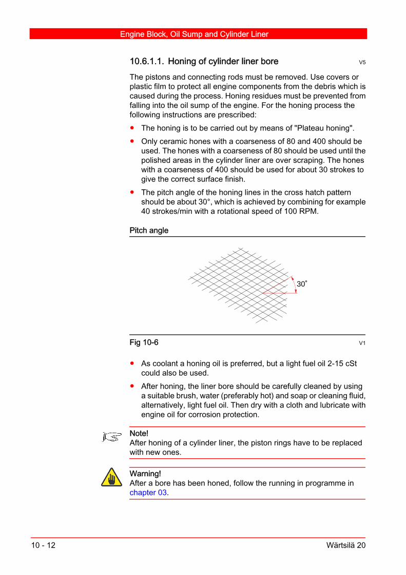
10.6.1.1. Honing of cylinder liner bore V5
The pistons and connecting rods must be removed. Use covers orplastic film to protect all engine components from the debris which iscaused during the process. Honing residues must be prevented fromfalling into the oil sump of the engine. For the honing process thefollowing instructions are prescribed: The honing is to be carried out by means of "Plateau honing". Only ceramic hones with a coarseness of 80 and 400 should be
used. The hones with a coarseness of 80 should be used until thepolished areas in the cylinder liner are over scraping. The honeswith a coarseness of 400 should be used for about 30 strokes togive the correct surface finish.
The pitch angle of the honing lines in the cross hatch patternshould be about 30°, which is achieved by combining for example40 strokes/min with a rotational speed of 100 RPM.
Pitch angle
30˚
Fig 10-6 V1
As coolant a honing oil is preferred, but a light fuel oil 2-15 cStcould also be used.
After honing, the liner bore should be carefully cleaned by usinga suitable brush, water (preferably hot) and soap or cleaning fluid,alternatively, light fuel oil. Then dry with a cloth and lubricate withengine oil for corrosion protection.
Note!After honing of a cylinder liner, the piston rings have to be replacedwith new ones.
Warning!After a bore has been honed, follow the running in programme inchapter 03.
Engine Block, Oil Sump and Cylinder Liner
10 - 12 Wärtsilä 20

10.6.2. Removing of cylinder liner V5
It is recommended that the crankshaft is turned to TDC and a pieceof plastic is put straight through the crankcase over the crank pin,preventing remaining cooling water or dirt to enter the oil sump.
1 Drain the engine cooling water.
2 Remove the cylinder head, see chapter 12
3 Remove the piston with connecting rod, see chapter 11
4 Mount the cylinder liner removing device 836001, according to Fig10-7.
5 Tension the nut (1) of the pull screw until the liner is held between theremoving device.
6 Lift the liner out of the engine block.
Engine Block, Oil Sump and Cylinder Liner
Wärtsilä 20 10 - 13

Removing and lifting of cylinder liner
836 001
1
2
1.Nut,2.Distinct mark,836001Extracting and lifting tool for cylinder liner
Fig 10-7 201054 V2
10.6.3. Inspection of cylinder liner V1
Clean the cylinder liner water side. The water side of the cylinder linercan be cleaned of deposits with a steel wire brush.
10.6.4. Mounting of cylinder liner V6
If more than one cylinder liner have been removed, check that theliners are installed in the same cylinders as before the overhaul. Theliners are marked with the cylinder numbers.
Engine Block, Oil Sump and Cylinder Liner
10 - 14 Wärtsilä 20

1 Check that all guide and contact faces of the engine block and cylinderliner are clean and intact.
2 Apply High-performance grease paste e.g Gleitmo 805 or similar onengine block and cylinder liner contact surfaces accordingly to figure.See Fig 10-9.
3 Mount a new shim for cylinder liner, if specified for the engine. Checkthat the new shim has the same thickness as the replaced one. ApplyHigh-performance grease paste e.g Gleitmo 805 on both sides of theshim.
4 Mount the lifting device for cylinder liner.
5 Check that the O-ring grooves of the cylinder liner are clean, and in‐sert new O-rings.
6 Lubricate the lower O-rings with grease or clean lubricating oil.
7 Lower the liner carefully into the bore of the engine block. When thelowest O-ring touches the engine block, align the liner so that the markon the liner is directed towards the driving end of the engine. Lowerfurther and press liner into position by hand.
8 Check the inner diameter of the cylinder liner, at the places shown inpicture.
Inner diameter
Fig 10-8 201050 V1
9 Mount the piston with the connecting rod, see chapter 11.
10 Mount the cylinder head, and refill the cooling water system, seechapter 12.
11 Check the O-ring seals from the crankcase side while circulatingcooling water. Apply 3 bar static pressure.
Engine Block, Oil Sump and Cylinder Liner
Wärtsilä 20 10 - 15

Mounting of cylinder liner
1
2 X
2
A
B
1.O-rings,2.Shim for cylinder liner,X.Apply grease paste from A to B
Fig 10-9 201056 V2
Engine Block, Oil Sump and Cylinder Liner
10 - 16 Wärtsilä 20

11. Crank Mechanism: Crankshaft,Connecting Rod, Piston V2
11.1. Crankshaft V3
The crankshaft is forged in one piece and provided with two counter‐weights per cylinder. The counterweights are fastened with twoscrews each. 4-cylinder engines have either integrated or separatecounterweights.At the driving end of the engine, the crankshaft is equipped with a V-ring for sealing the crankcase. The axial clearance is controlled by acombined flywheel/thrust bearing. A shrink-fitted gear wheel for driv‐ing the camshaft is located at the driving end.The main bearings are described in Chapter 10: Engine Block withOil Sump and Cylinder Liner.At the free end, there is a gear for driving the water pumps and thelubricating oil pump. Usually, a vibration damper is also installed. Thedamper can be either mechanical or viscous. See the instructions forthe vibration damper provided separately, if the engine is equippedwith one. In case there is no vibration damper, a tuning mass is usedinstead.The crankshaft can be turned by a manual turning device operatingthe flywheel.The lubricating oil is supplied through the side screw holes in the en‐gine block to the main bearings. The oil flows further from the mainbearing through the bores in the crankshaft to the connecting rod bigend bearing and up in the connecting rod and piston. Due to a specialdesign of the bores in the crankshaft, the flow to the connecting rodis intermittent. The oil is forced to flow in one direction only.
11.1.1. Balancing of crankshaft V3
The crankshaft is balanced with counterweights on the crank webs,two weights per cylinder journal. The counterweights are located bya guide pin and fastened to the web with two bolts. 4 cylinder engineshave either integrated or separate counterweights.
Data and dimensionsMaterial: Forged, alloyedsteelWeight:1000 kg (8L20)
Data and dimensionsMaterial: Steel plateWeight: 21 kg
Crank Mechanism: Crankshaft, Connecting Rod, Piston
Wärtsilä 20 11 - 1

Positions of counterweights
AA-A
7
A
1
1. Guide pin 2. Counter weights.
Fig 11-1 V2
11.1.2. Crankshaft alignment V5
1 Turn crank of the first cylinder near BDC (bottom dead centre) andattach the crankshaft dial indicator to the centre marks in the twocrank webs. The distance between the indicator and the connectingrod should be as small as possible.
2 Set indicator at zero.
3 Read deflections when turning crank to the rear side, TDC (top deadcentre), operating side and BDC. Record readings in the measure‐ment record WV98V036 "Crankshaft alignment".
Note!During the alignment procedure the crankshaft should be turned inthe anti-clockwise direction, only.
4 Repeat this procedure with other cylinders.
5 Following limits of misalignment are stated for an engine having nor‐mal running temperature (within 5 minutes after running at 60 % loador higher for 6 h or more):a) on the same crankThe difference between two diametrically opposed readings must notexceed 0.07 mm after installing or realigning. Realignment is neces‐sary if this limit is exceeded by more than 0.02 mm.b) on two adjacent cranksThe difference between two corresponding readings must not exceed0.04 mm. Realignment is necessary if this limit is exceeded, exceptfor crankpin 1 and 2.
Crank Mechanism: Crankshaft, Connecting Rod, Piston
11 - 2 Wärtsilä 20
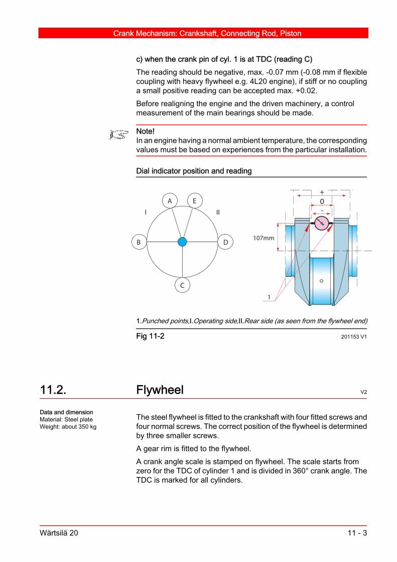
c) when the crank pin of cyl. 1 is at TDC (reading C)The reading should be negative, max. -0.07 mm (-0.08 mm if flexiblecoupling with heavy flywheel e.g. 4L20 engine), if stiff or no couplinga small positive reading can be accepted max. +0.02.Before realigning the engine and the driven machinery, a controlmeasurement of the main bearings should be made.
Note!In an engine having a normal ambient temperature, the correspondingvalues must be based on experiences from the particular installation.
Dial indicator position and reading
B
C
D
EA
I II0+
-
107mm
1
1.Punched points,I.Operating side,II.Rear side (as seen from the flywheel end)
Fig 11-2 201153 V1
11.2. Flywheel V2
The steel flywheel is fitted to the crankshaft with four fitted screws andfour normal screws. The correct position of the flywheel is determinedby three smaller screws.A gear rim is fitted to the flywheel.A crank angle scale is stamped on flywheel. The scale starts fromzero for the TDC of cylinder 1 and is divided in 360° crank angle. TheTDC is marked for all cylinders.
Data and dimensionMaterial: Steel plateWeight: about 350 kg
Crank Mechanism: Crankshaft, Connecting Rod, Piston
Wärtsilä 20 11 - 3

The flywheel position indicator is marked with a scale to read the en‐gine crank angles, at an accuracy of one (1) degree on the graduationof the flywheel.
Reading of flywheel indicator
54321012345
340
350
0
1
2
54321012345
0
350
340
35 4
TDC
TDC
1. Flywheel Position indicator 2. TDC 3. Clockwise rotation 4. Flywheel5. Anticlockwise rotation.
Fig 11-3 V3
11.2.1. Chamfered gear rim V1
The gear rim is chamfered to improve the engagement of the air start‐er bendix and thus minimize the starting failures caused by a tooth totooth contact.The chamfering of the gear rim teeth is dependent of the rotating di‐rection (clockwise, CW, or counterclockwise, CCW).
Crank Mechanism: Crankshaft, Connecting Rod, Piston
11 - 4 Wärtsilä 20

Chamfered gear rim
CCW
CW
A
B
A
B
Fig 11-4 201187 V1
11.2.2. Replacing the gear rim V6
If the gear rim is damaged or worn, it can be replaced without remov‐ing the flywheel. Follow the steps given below:
1 Open the screws holding the gear rim and remove the gear rim fromthe flywheel.
2 Cut the ring in to the suitable pieces. Ensure that the flywheel is notdamaged during this operation.
3 The spare part gear rim is delivered in two pieces, which can easilycan be mounted on the flywheel. Additional screw holes for the ringhalf ends are pre-machined at the factory.
4 Mount the gear rim halves with (2 mm) feeler gauges between the twosplit halves and pre-tighten the fastening screws.
5 Measure the base tangent length over 30 teeth or chosen number ofteeth, if no suitable calliper is available. Compare the measured tan‐gent length over the split area and tighten the fastening screws tostated torque. See, chapter 07: Tightening torques for screws andnuts.
Crank Mechanism: Crankshaft, Connecting Rod, Piston
Wärtsilä 20 11 - 5

Base tangent length over the number of teeth spanned
W/k = 317.748 -0.320-0.640 / 30
1
1. Gear rim half
Fig 11-5 201161 V2
11.3. Turning device V1
The crankshaft can be turned by a manual turning device operatingon the flywheel. The turning device consists of a gear, which is oper‐ated with a ratchet. The rotational direction for turning can be reversedby altering the ratch position of the ratchet.
Note!The engine must not be started while the turning gear is engaged.
11.4. Connecting rod and piston V1
The connecting rod is of the drop-forged type with H-section shaft.The big end is of "stepped split line" design and precision serrated atthe mating surfaces. This design offers the maximum crank pin di‐ameter but still makes it possible to pull the connecting rod throughthe cylinder liner.The big end bearing shells are, for correct assembling, axially guidedby lugs. The design of the crankshaft enables the use of a non-grooved upper bearing shell.The two connecting rod screws are hydraulically tightened.
Data and dimensionMaterial: Special steel,drop forgedWeight: 38 kgBearing type: Bi-metalbearing
Crank Mechanism: Crankshaft, Connecting Rod, Piston
11 - 6 Wärtsilä 20

The gudgeon pin bearing bush is stepped to give a larger bearingsurface on the more loaded lower side. It is lubricated via bores in theconnecting rod.The gudgeon pin is of the full floating design, secured axially withretainer rings. The oil flow from the connecting rod is passed throughthe gudgeon pin further up to the piston. The gudgeon pin has shrinkfitted plugs in the ends.
11.4.1. General description of piston V1
The piston is of composite type with a forged steel or a nodular castiron skirt and a forged steel crown screwed together. The piston skirthas a phosphate/graphite overlay.The piston crown is cooled with lubricating oil by means of the cocktailshaker effect. The lubricating oil is led from the main bearing, throughthe bores in the crankshaft, to the big end bearing, and further throughthe bores in the connecting rod, gudgeon pin and piston skirt, up tothe cooling space, from where it is drained back to the oil sump.The pistons are provided with Wärtsilä patented skirt lubricating sys‐tem.The combustion chamber in the top of the piston is deep, preventingthe fuel jets to touch the cylinder liner.The compression ring grooves are hardened for better wear resist‐ance.
Note!Always handle the pistons with care. Do not damage or remove thephosphate/graphite overlay.
The piston ring set consists of two compression rings and one spring-loaded oil control ring. In this three-ring pack, every ring is speciallydimensioned and profiled for the task it has to perform. The top ringis provided with a special wear resistant coating. The second com‐pression ring is chrome-plated. The oil control ring is a spring-loaded,chrome-plated oil scraper ring.The side to be upwards of the compression rings is always marked"TOP".
Data and dimensionComposite pistonMaterial skirt: Nodularcast iron or forged steelMaterial crown: ForgedsteelScrew: 10.9Weight: 22 kg
Crank Mechanism: Crankshaft, Connecting Rod, Piston
Wärtsilä 20 11 - 7

11.4.2. Removing and dismantling the piston andconnecting rod V5
1 Remove the cylinder head. For instructions, see chapter 12 section12.2.a ) Scrape off carbon deposits carefully from the slots of the anti-
polishing ring and around the upper part of the cylinder liner.b ) Cover the piston top with a cloth or paper pressed tightly (by an
old piston ring) against the cylinder wall to collect the depositsremoved.
2 Remove the anti-polishing ring.a ) Turn the engine. The piston pushes the anti-polishing ring out.Use the tool 836002 to extract the ring. Use 836003 to keep the linerin place during the extracting procedure.
3 Clean the threaded hole in the piston crown. Fasten the lifting tool832002.
Removing the antipolishing ring
12
1. Anti-polishing ring dismantling tool (836002) 2. Cylinder liner holders(836003)
Fig 11-6 201176 V2
Data and dimensionWeight: 75 kg
Crank Mechanism: Crankshaft, Connecting Rod, Piston
11 - 8 Wärtsilä 20

4 Turn the crankshaft about 55° from TDC towards the operating sidefor the cylinder concerned. See, Fig 11-7.
5 Lift the distance sleeves 861153 into position on the connecting rodscrews. Screw on the hydraulic tools 861159 with extension pieces861157.
Note!Before and after applying the pressure on the hydraulic tool, checkthat there is clearance between the distance sleeves and the engineblock. If necessary, turn the crankshaft slightly to get the clearancefor both sleeves.
Dismantling of piston and connecting rod
861 159
861 153
861 159
861 157
832 002
B*
B*
A
AOperating Side 861 153Distance sleeve861 157Extension piece861159Hy‐draulic Cylinder832 002Lifting tool for pistonB*Check the clearance
Fig 11-7 201175 V2
6 Connect the hoses of the hydraulic pump, and open the connectingrod nuts. See, section 07.3.
Crank Mechanism: Crankshaft, Connecting Rod, Piston
Wärtsilä 20 11 - 9

Dismantling
Hydraulic oil
1. Screw on cylinder by hand. 2. Connect hoses, open valve. Tighten cylindersby hand. 3. Screw cylinders 180° counter- clockwise. 4. Close valve, rise pres‐sure. 5. Open the nut about half a turn. 6. Open release valve, remove tool.
Fig 11-8 HYD2A V2
7 Remove the hydraulic tool and the distance sleeve from the connect‐ing rod studs.
8 Open the lower nut and remove the lower stud. Use the stud extract‐ing tool 803011. The locking screw of the tool has left-hand threads.
9 Repeat the same procedure as above with the upper nut and stud.Lift the big end bearing cap together with the bearing shell out of theengine.
10 To remove the upper big end bearing shell, lift the piston a little. Whenlifting the piston, take care not to damage the crank pin or the cylinderliner wall.
11 Cover the crank pin oil holes with tape.
12 Lift the piston together with the connecting rod out of the engine.When lifting the piston, take care not to damage the cylinder liner wall.
13 Remove the retainer ring from the gudgeon pin hole in the piston onthe side where the gudgeon pin drawing number is located. Use thepliers for the retainer ring, 843004.
Note!Never compress the retainer ring more than necessary to remove itfrom the groove.
14 Drive out the gudgeon pin from the opposite side. In low tempera‐tures, the gudgeon pin may get stuck. Heating the piston to about30°C for example, in oil.
Crank Mechanism: Crankshaft, Connecting Rod, Piston
11 - 10 Wärtsilä 20

15 If the rings and grooves require for example cleaning or measuring,remove the piston rings. Use the pliers 843003. Before removingthem, note the position of the rings to ensure mounting in the samegrooves. The design of the pliers prevents overstressing of the rings.Using other means may overstress the rings.
11.4.3. Maintaining the piston, piston rings andconnecting rod bearings V5
1 Clean all the parts carefully. Remove the piston rings. Remove carbondeposits from the piston and piston ring grooves. Special care shouldbe taken not to damage the piston.
Caution!Never use emery cloth on the piston skirt.
Cleaning is easier if coked parts are soaked in kerosene or fuel oil.An efficient carbon solvent such as ARDROX No. 668 or similarshould preferably be used to facilitate cleaning of the piston crown.When using chemical cleaning agents, take care not to clean pistonskirt with such agents because the phosphate-graphite overlay maybe damaged.
2 Measure the height of the piston ring grooves.
3 Dismantle the composite piston for inspection of mating surfaces be‐tween the piston skirt and piston crown. Inspect and clean oil spaces.See, section 07.1.6
Note!Always fit new piston rings when a new cylinder liner has been honedor fitted.
4 Check the gudgeon bearing bush and big end bearing bore.a ) When measuring the big end bearing bore, tighten the connect‐
ing rod cap and nuts to the stated pressure.b ) Determine the bearing shell wear by measuring the thickness.
Use a ball anvil micrometer for this. See the wear limits in Chapter06: Clearances and wear limits.
c ) When replacing the big end bearing shells, always change boththe upper and the lower bearing shells.
Note!Mark new bearings with the bearing number.
Crank Mechanism: Crankshaft, Connecting Rod, Piston
Wärtsilä 20 11 - 11
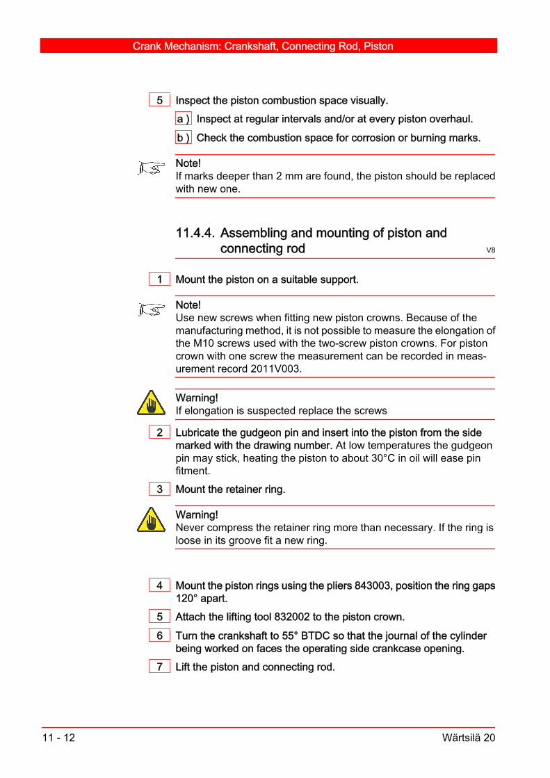
5 Inspect the piston combustion space visually.a ) Inspect at regular intervals and/or at every piston overhaul.
b ) Check the combustion space for corrosion or burning marks.
Note!If marks deeper than 2 mm are found, the piston should be replacedwith new one.
11.4.4. Assembling and mounting of piston andconnecting rod V8
1 Mount the piston on a suitable support.
Note!Use new screws when fitting new piston crowns. Because of themanufacturing method, it is not possible to measure the elongation ofthe M10 screws used with the two-screw piston crowns. For pistoncrown with one screw the measurement can be recorded in meas‐urement record 2011V003.
Warning!If elongation is suspected replace the screws
2 Lubricate the gudgeon pin and insert into the piston from the sidemarked with the drawing number. At low temperatures the gudgeonpin may stick, heating the piston to about 30°C in oil will ease pinfitment.
3 Mount the retainer ring.
Warning!Never compress the retainer ring more than necessary. If the ring isloose in its groove fit a new ring.
4 Mount the piston rings using the pliers 843003, position the ring gaps120° apart.
5 Attach the lifting tool 832002 to the piston crown.
6 Turn the crankshaft to 55° BTDC so that the journal of the cylinderbeing worked on faces the operating side crankcase opening.
7 Lift the piston and connecting rod.
Crank Mechanism: Crankshaft, Connecting Rod, Piston
11 - 12 Wärtsilä 20

8 Lubricate the piston and place the clamp device for piston rings843002 around the piston rings. Check that the piston rings are cor‐rectly positioned in their grooves.
9 Oil all the surfaces of the upper big end bearing shell. Mount thebearing shell so that the lug fits into its groove in the connecting rod.
Caution!Use of glue compound on a bearing shell is prohibited.
10 Remove protecting cover from the crank pin oil holes and lubricatethe crank pin with clean engine oil.
11 Lower the piston and connecting rod carefully into the cylinder liner.Remove the piston ring clamp 843002.
12 Lower the piston further until the connecting rod is placed on the crankpin.
13 Oil all the surfaces of the lower big end bearing shell. Mount thebearing shell so that the lug fits into its groove in the bearing cap.
14 Check the bearing shell alignment.
Checking the bearing shell alignment
1 2
1. Incorrectly fitted, 2. Correctly fitted
Fig 11-9 V3
15 Fit the bearing cap.
16 Mount the lower and upper connecting rod screws. Tighten using thestud remover tool 803011 to the specified torque. See Chapter 07:Tightening torques and use of hydraulic tools
Note!Replace the screws every 24,000 operating hours at latest.
Crank Mechanism: Crankshaft, Connecting Rod, Piston
Wärtsilä 20 11 - 13

17 Lift the distance sleeves 861153 over the connecting rod nuts andscrew on the hydraulic cylinder 861159 with extension piece861157.
18 Connect the hoses from the hydraulic cylinders to the high pressurepump.
19 Open the valve and tighten the hydraulic cylinders using a ½ inchdrive ratchet wrench and extension.
Caution!Check the clearance between the distance sleeves and the engineblock, before and after applying pressure to the hydraulic tool. If nec‐essary turn the crankshaft slightly to get the clearance for bothsleeves.
20 Close the valve, raise the pressure in two steps to the stated pres‐sure. See Chapter 07: Tightening torques and use of hydraulic tools.
21 Tighten the nuts using the pin.
22 Open the pump valve and release the pump pressure.
23 Remove the hydraulic cylinders, hydraulic pipes, pin and distancesleeves.
24 Check that the connecting rod moves axially after tightening.
25 Mount the side covers.
26 Remove lifting yoke and disengage turning device.
27 Mount the anti-polishing ring and cylinder head. See Chapter 12: Re‐moving and mounting the cylinder head.
Crank Mechanism: Crankshaft, Connecting Rod, Piston
11 - 14 Wärtsilä 20

12. Cylinder Head with Valves V5
The cylinder heads are cast of special-quality grey iron. Each headincludes two inlet valves, two exhaust valves, a centrally located in‐jection valve and an indicator valve. The cylinder heads are individ‐ually tightened to the cylinder liner with four studs and hydraulically-tightened nuts. A metallic gasket seals the space between the cylin‐der liner and the cylinder head. The combustion air and the exhaustgas channels are connected to a common multi-duct, which is con‐nected to the cylinder head by six screws.The four screw and box-cone design is a traditional and well-provendesign for cylinder heads. The advantage of four screws is not onlythe ease of maintenance but it also allows the design of large andcorrectly-designed channels for combustion air and exhaust gases.In a heavy-fuel engine the correct material temperatures are a crucialfactor to ensure long lifetime of the components being in contact withcombustion gases. Efficient cooling and a rigid design is best ach‐ieved with the "double deck" design in which the flame plate is rela‐tively thin and the mechanical load is transferred to the strong inter‐mediate deck. The most sensitive areas of the cylinder head arecooled by drilled cooling channels optimized to distribute the waterflow evenly around valves and the centrally-located fuel injector.The injection valve is described in chapter 16.
Cylinder head assembly
112
9 10
23
4 5
6
8 11
7
1. Bearing bracket 2. Rocker arm 3. Yoke for valves 4. Yoke for injection valve5. Cylinder head 6. Rotocap 7. Screws for connection piece 8. Exhaust valveseat 9. Exhaust valve 10. Inlet valve 11. Inlet valve seat 12. Indicator valve
Fig 12-1 201259 V2
Data and dimensionsMaterial: Cast grey ironTensile strength:250-300 N/mm2
Weight: 92 kgCombustion space- design pres.: 200 bar- test pressure: 225 barWater space- test pressure: 10 barOperation temperature:- water return: 95°C"
Cylinder Head with Valves
Wärtsilä 20 12 - 1

12.1. Functions of the cylinder head drilling V3
The flame plate of the cylinder head is a part of the combustion cham‐ber. During combustion, the flame plate is exposed to high pressuresand high temperatures. Combustion air is led from the air receiverthrough the multiduct and the cylinder head inlet channel into the cyl‐inder. The air flow is governed by two inlet valves in the flame plate.In a similar way, the exhaust gas is led from the cylinder through thecylinder head exhaust channel and the multiduct to the exhaust mani‐fold. The gas flow is governed by two exhaust valves.The multi-orifice injection valve and its sleeve are centrally mountedin the cylinder head. The sleeve holds the injection valve in positionand separates the injection valve from the cooling water.Each cylinder head is individually cooled by the water flow that entersthe cylinder head from the cylinder jacket through a single bore. Thereare drilled cooling passages to the exhaust valve seats. After passingover the flame plate and the seat rings, the water flows out through asingle bore into the multiduct. The cooling water flows out from thecylinder head directly to the multiduct. Any air or gas in the coolingwater is vented from the top of the multiduct.The valve mechanism is lubricated from the lubricating oil system.The oil is led through a pipe from the valve tappet guide in the multi‐housing to the rocker arm bracket. All other flows into the cylinderhead are through drillings.The controlled leakage from the injection valve is returned throughthe protection pipe.The fuel pipe is also protected against hazardous leaks from the highpressure connection stud.
12.2. Removing the cylinder head V6
1 Drain the cooling water.
2 Open the indicator valves.
3 Remove the caps of the cylinder head screws.
4 Remove the cylinder head cover.
5 Turn the engine until both the inlet and exhaust valves are closed.Remove the valve rocker arm bracket and the push rods.
6 Remove the fastening screws of the multiduct.
7 Remove the injection pipe, the fuel leak pipe, and lube oil pipes, wherenecessary. Protect all the pipe connections.
Cylinder Head with Valves
12 - 2 Wärtsilä 20

8 Put on the distance sleeves 861156 and hydraulic cylinders861159. Loosen the cylinder head nuts.
Dismantling with hydraulic tools
Hydraulic oil
1. Mount the cylinders by hand. 2. Connect hoses, open valve. Tighten cylindersby hand. 3. Turn the cylinders 180° counter-clockwise. 4. Close valve, risepressure. 5. Open the nut about half a turn. 6. Open release valve, remove tool.
Fig 12-2 HYD V1
9 Remove the cylinder head nuts.
10 Lift off the cylinder head. Use the lifting tool 832004.
Lifting the cylinder head
832 004
832 004 Lifting tool for cylinder head.
Fig 12-3 201255 V1
11 Cover the cylinder opening with a piece of plywood or somethingsimilar.
12 Refit the caps to protect the screw threads.
Cylinder Head with Valves
Wärtsilä 20 12 - 3

12.2.1. General maintenance of the cylinder head V5
General maintenance of the cylinder head includes a thorough visualcheck, including water cooling spaces. Possible scale formation incooling spaces can disturb the cooling effect and therefore it has tobe cleaned, See chapter 02: Fuel, Lubricating Oil, Cooling Water.Combustion spaces must be inspected carefully for possible wear.Valve seats and the injection valve sleeve should be inspected forpossible water leakage and replaced if necessary.Valve guides should be checked and replaced if worn. O-rings mustbe replaced with new ones at every overhaul.The sealing surfaces between the cylinder head and cylinder linershould be inspected and reconditioned if necessary.
12.2.2. Mounting the cylinder head screws V1
1 Inspect the cylinder head screws for corrosion. When corrosion pits with a depth of less than 0.1 mm is found,
polish away the pits with a small hand grinder. If corrosion is deeper than 0.1 mm, change the screw.
Note!Corrosion depth in threads can be hard to determine. Change thescrews, whenever in doubt.
2 Lubricate the threads of the screw. Use a thin layer of Mobilarma 524or corresponding corrosion protection agent.
Cylinder Head with Valves
12 - 4 Wärtsilä 20

Lubricating the threads of the screw
1
2
3
1. O-ring 2. Compartment filled with Mobilarma 524 3. Threads of the screwlubricated with Mobilarma 524.
Fig 12-4 V3
3 Mount the screw and tighten to a specified torque.
Caution!Do not exceed the maximum tightening pressure.
Caution!Change the cylinder head screws, if the maximum pressure is ex‐ceeded when using the hydraulic tool.
4 Fill the compartment between the screw and the engine block withMobilarma 524 or corresponding corrosion protection agent.a ) When filling the corrosion protection agent leave about 2 mm
space between O-ring and corrosion protection.5 Mount the O-ring.
Note!Change the O-rings at every piston overhaul.
12.2.3. Mounting the cylinder head V8
1 Clean the sealing surfaces. Fit new cylinder head and multiduct gas‐kets.
Cylinder Head with Valves
Wärtsilä 20 12 - 5

2 Fit new O-rings to the cooling water jacket and the push rod protectingpipe.
3 Lubricate the O-ring sealing surfaces with grease or oil.
4 Attach the lifting tool 832004 to the cylinder head.
5 Lift on the cylinder head. Pay special attention to the multiduct gasket,ensuring that it is intact and correctly mounted.
6 Screw on the cylinder head nuts and tighten by hand.
Note!Before hydraulically tightening the cylinder head nuts, it is very im‐portant to ensure that multiduct sealing surface is properly alignedwith the cylinder head sealing surface. Improper alignment can causewater leakage into the cylinder.
7 Connect the multiduct, fit the screws and tighten by hand.
8 Put on the distance sleeves 861156, screw on the hydraulic cylin‐ders 861159 and proceed with tightening of cylinder head nuts. Tight‐ening in two steps is recommended.
Assembling with hydraulic tool
Hydraulic oil
1. Mount the nuts, attach the distance sleeve. Mount the cylinders by hand. 2.Connect hoses, open valve. 3.Tighten the cylinders by hand. 4. Close the valveand pump pressure to the stated value. 5. Turn the nuts until close contact toface. 6. Open the valve. 7. Repeat steps 4, 5 and 6. 8. Remove the tool set.
Fig 12-5 HYD V1
9 Tighten the multiduct screws to the torque stated in 07.1.3.
10 Connect the pipes, the fuel leak pipe, lubricating oil pipes and theinjection pipe.
11 Fit the push rod protecting pipes.
12 Fit the push rod and the rocker arm bracket.
13 Adjust the valve clearance, see section 12.2.5. For clearances, seesection 06.1.
Cylinder Head with Valves
12 - 6 Wärtsilä 20

14 Put on the cylinder head cover, remember to put new hose gasket forthe cover. Spot glue the gasket in place using Bostik-glue A3.
15 Apply the protecting caps to the cylinder head screws.
16 Before starting, fill the engine cooling water system. Turn the crank‐shaft two revolutions, with the indicator cocks open.
Example Glue points
Fig 12-6 201256 V1
12.2.4. Valve clearance V2
Valve clearances, cold engine:inlet valves 0.4 mmexhaust valves 0.8 mm
Note!Before checking or adjusting valve clearance, allow the engine to coolfor at least a couple of hours and ensure that the automatic start andthe priming pumps are disconnected.
12.2.4.1. Checking the valve clearance V3
1 Remove the cylinder head cover.
2 Turn the crankshaft to TDC at ignition for the cylinder concerned.
3 Using a feeler gauge, check the valve clearance between the contactsurfaces of the yoke and the rocker arm shoe. There should be onlyslight resistance when the feeler gauge is slid in and out. If necessary,adjust according to section 12.2.4
4 Refit the cylinder head cover.
Cylinder Head with Valves
Wärtsilä 20 12 - 7

12.2.5. Adjusting valve clearance and yoke V6
Adjusting valve clearance
a b c
23
4
1
1. Adjusting screw for rocker arm 2. Counter nut 3. Adjusting screw for valveyoke 4. Counter nut
Fig 12-7 201258 V1
1 Turn the crankshaft to TDC at ignition for the cylinder concerned.
2 Loosen the counter nuts of the adjusting screws on the rocker arm (2)and on the yoke (4). Turn the adjusting screws counterclockwise toprovide ample clearance.
3 Press the fixed end of the yoke against the valve stem by pressingdown the adjustable end.a ) Screw down the adjusting screw (3) until it touches the valve end.
b ) Note the position of the spanner (position a).
c ) Press down the fixed end.
Cylinder Head with Valves
12 - 8 Wärtsilä 20

d ) Keep on screwing down while the yoke tilts, until the guide clear‐ance is on the other side and the fixed end of the yoke starts liftingfrom the valve stem.
e ) Note the position of the spanner (b).
4 Turn the adjusting screw counterclockwise to the middle position "c"between "a" and "b". Lock the counter nut of the adjusting screw.
5 Put a feeler gauge corresponding to the valve clearance between thecontact surfaces of the yoke and the rocker arm shoe.a ) Tighten the adjusting screw (1) until the feeler gauge can be
moved to and fro only with slight force.b ) Hold the adjusting screw, and tighten the counter nut. Check that
the clearance has not changed while tightening.
12.3. Exhaust and inlet valves and seat rings V2
The cylinder head has four valves fitted, two inlet valves and two ex‐haust valves. All the valves are made of surface-treated heat resistantsteel. The inlet valves are bigger than the exhaust valves.The valves move in cast iron guides, which are press fitted in thecylinder head and can be replaced. The valve guides have an O-ring(sealing against the valve stem), which is located at the top of theguide bore.The valves are provided with one valve spring per valve and valverotating devices or valve spring retainers.The valve seat rings are fitted in the cylinder head for both inlet andexhaust valves. The exhaust valve seat rings are water cooled andtherefore provided with one or two O-rings per seat.
12.3.1. Dismantling valves V4
1 Fit the tool 846010 according to Fig 12-8.
Data and dimensionsMaterial:High quality steelDiameter-inlet valve: 73 mm-exhaust valve: 66 mm
Valve seat ringMaterial: High qualitysteelAngle-inlet seat: 20°-exhaust seat: 30°
Cylinder Head with Valves
Wärtsilä 20 12 - 9

Tool assembly for dismantling valves
A
A. Fastening screw
Fig 12-8 201252 V1
2 Compress the springs about 15-20 mm with the screw.
3 Knock at the centre of the valve discs with a soft piece of wood, plastichammer or similar, so that the valve cotters come loose and can beremoved.
4 Unload the tool.
5 Spring retainers and springs can now be removed.
6 Note the marks on the valves or mark them according to Fig 12-9 sothey can be re-installed into the same guide if they are in good con‐dition.
Cylinder Head with Valves
12 - 10 Wärtsilä 20

Marking of the valves (view from the underside)
A D
CB
21
A. Inlet valve, B. Inlet valve, C. Exhaust valve, D. Exhaust valve1. Air in, 2. Ex out
Fig 12-9 201254 V1
12.3.2. Checking and reconditioning of valves andseats V5
1 Clean the valves, seats, ducts and guides as well as the underside ofthe cylinder head.
2 Check the wear and erosion on the valve head according to Fig12-10. The margin width "Y" should be more than 4.5 mm (nominal5.5 mm) and dimension "Z" should be less than 1 mm. If the valuesexceed these limits the valve must be replaced.
Cylinder Head with Valves
Wärtsilä 20 12 - 11
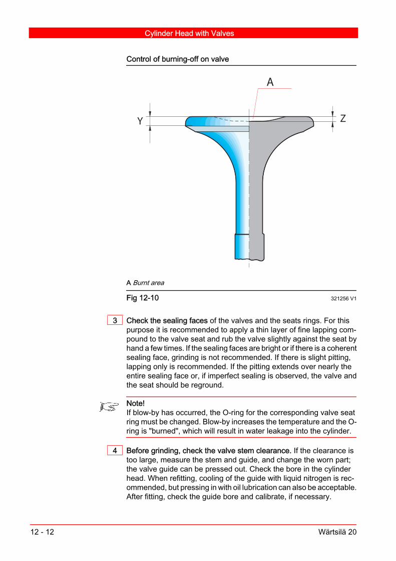
Control of burning-off on valve
ZY
A
A Burnt area
Fig 12-10 321256 V1
3 Check the sealing faces of the valves and the seats rings. For thispurpose it is recommended to apply a thin layer of fine lapping com‐pound to the valve seat and rub the valve slightly against the seat byhand a few times. If the sealing faces are bright or if there is a coherentsealing face, grinding is not recommended. If there is slight pitting,lapping only is recommended. If the pitting extends over nearly theentire sealing face or, if imperfect sealing is observed, the valve andthe seat should be reground.
Note!If blow-by has occurred, the O-ring for the corresponding valve seatring must be changed. Blow-by increases the temperature and the O-ring is "burned", which will result in water leakage into the cylinder.
4 Before grinding, check the valve stem clearance. If the clearance istoo large, measure the stem and guide, and change the worn part;the valve guide can be pressed out. Check the bore in the cylinderhead. When refitting, cooling of the guide with liquid nitrogen is rec‐ommended, but pressing in with oil lubrication can also be acceptable.After fitting, check the guide bore and calibrate, if necessary.
Cylinder Head with Valves
12 - 12 Wärtsilä 20

12.3.3. Lapping V5
If slight pits exist on the sealing faces, they can be lapped by hand:1 Fit the turning tool to the valve.
2 Apply a thin layer of lapping compound to the sealing surface of thevalve; No.1 for coarse lapping, No.3 for fine lapping.
3 Rotate the valve back and forth towards the seat using turning tool841001. Lift the valve from the seat at intervals while lapping.
4 Remove the smallest possible amount of material, as the sealingfaces have hardened during operation and are valuable. It is not nec‐essary to grind off all pits.
5 Clean the valve and the seat carefully after lapping.
12.3.4. Machine grinding V5
If there is deep pitting or other damage, the valve and seat should beground by machine.
Note!The valve should be cooled by water during the grinding.
Valve
ø min.
Fig 12-11 201257 V2
1 Seat face of the inlet valve: The seat angle of the inlet valve is 20°with a tolerance of ± 0.05°. Minimum allowable inner diameter ofsealing surface after grinding is 52 mm; after that, the valve must bereplaced by a new one.
2 Seat face of the exhaust valve: There are two alternative types ofexhaust valve (Stellit and Nimonic). The seat angle of the exhaustvalve is 30° with a tolerance of -0° - +0.10° (to achieve contact with
Cylinder Head with Valves
Wärtsilä 20 12 - 13

the seat ring at the inner edge of the valve seat.) The minimum al‐lowable inner diameter of sealing surface after grinding is 48 mm;after that, the valve must be replaced with a new one.
Seat face of the valves
A B
20 0,0
5
30
0,1
0
A. Inlet, B. Exhaust
Fig 12-12 201262 V1
3 Seat ring for the inlet valve: The seat angle of the inlet valve seat ringis 20° with a tolerance of ± 0.05°. The seat can be ground until theouter seat diameter is 78 mm; after that, the ring must be replacedwith a new one.
4 Seat ring for the exhaust valve: The seat angle of the exhaust valveseat ring is 30° with a tolerance of 0° - +0.10°. The seat can be grounduntil the valve contact section mark has disappeared. If the sectionmark disappears at machining, it is recommended to replace the ring.Aim to get a contact to the seat ring at the inner edge of the valveseat.
Exhaust valve seat ring
67,5
30+0,1-0
68,6
Fig 12-13 201261 V2
Cylinder Head with Valves
12 - 14 Wärtsilä 20

Note!After grinding, a light lapping is recommended to provide contact be‐tween valve and seat.
12.3.5. Change of seat ring
12.3.5.1. Removing the old seat rings with the hydraulicextractor V5
The seat rings can most conveniently be removed with a special hy‐draulic extractor, which can be ordered from the engine manufacturer.If the extractor is not available, a scrapped valve can be used. See12.3.5.2.
1 Assemble the extractor according to Fig 12-14. Notice the differencein assembly for the inlet and exhaust seat.
2 Tension the extractor by tightening the axial screw.
3 Pressurize the extractor to withdraw the seat ring.
4 Open the pump valve to release the pressure, disconnect the hosesand dismantle the extractor.
Example Removing an old seat ring
A B
Hydraulic oil
834050
837024
834050
837018
861161
A. Inlet, B. Exhaust
Fig 12-14 201263 V1
Cylinder Head with Valves
Wärtsilä 20 12 - 15

12.3.5.2. Removing the old valve seat with using thescrapped valve V3
The seat rings can most conveniently be removed with a special hy‐draulic extractor, which can be ordered from the engine manufacturer.If the extractor is not available, a scrapped valve can be used.
1 Weld a scrapped valve to the seat using electric beam welding. Forease of welding, machine the valve head to a diameter of 55-60 mm.
Note!Protect the flame plate and the joint surfaces of the cylinder headwhen welding.
2 Press or knock out the ring but be careful not to damage the valveguide.
12.3.5.2.1. Fitting a new inlet valve seat ring V8
1 Check the bore diameter in the cylinder head. See section 06.2
2 Before fitting the valve seat, chill the seat in liquid nitrogen to -190°C,and ensure that the cylinder head temperature is at least 20°C. If liquidnitrogen is not available, put the seat in a freezer, and heat the entirecylinder head so that the seat head temperature difference is at least120°C.
Note!Heat up the entire cylinder head, not only the seat bore.
3 Check the eccentricity of the sealing face in relation to the valveguide. If it exceeds 0.1 mm, grind the seat surface in a seat grindingmachine.
12.3.5.2.2. Fitting a new exhaust valve seat ring V8
There are two types of exhaust valve seat rings, depending on theinstallation.
Exhaust valve seat rings
1.
13.5
11.5
2.
1. Exhaust valve seat ring with two O-rings. 2. Exhaust valve seat ring with oneO-ring.
Fig 12-15 201260 V2
Cylinder Head with Valves
12 - 16 Wärtsilä 20

Note!The seat rings are not interchangeable because of different pocketand seat geometry.
1 Clean the bore carefully with a grit 400 or finer emery cloth.
2 Check the bore diameter in the cylinder head. See, chapter 06: Clear‐ances and wear limits at 20°C.
3 Cool the seat ring between -20 and -25 °C prior to fitting.
Caution!Temperature lower than -25 °C may damage the O-ring(s) during as‐sembly.
4 Heat up the entire cylinder head to 100°C by means of either steamor a gas burner. If steam is used it may be easier if the steaming isdone within a closed box.
Note!It is important that the entire cylinder head is heated up, not only theseat bore.
5 Mount the O-ring(s) on the cooled valve seat.
6 Apply soap-water solution to lubricate the O-ring(s).
7 If the exhaust valve seat ring is mounted with one O-ring: Clean with Loctite 7063. Apply Loctite 620 to the cylinder head. Loctite must only be applied
to the larger bore (Ø 78) without O-ring. Not to the smaller borewhere the O-ring fits.
For more information about the use of Loctite, see section 12.3.68 Mount the exhaust valve seat using one of following methods:
Put the seat rings into a guide bush and press in the seat with aguided arbor. It is also possible to use a special tool (837032)which can be ordered from the engine manufacturer.
Insert the seat ring using an old scrapped exhaust valve. Do notuse an exhaust valve which is to be reused. Knock/push on thevalve until the seat ring is correctly seated.
Note!It is recommended that the exhaust seat O-rings are always replacedwhen overhauling the cylinder head.
Note!Mounting of a exhaust valve seat ring should be done carefully so thatthe seat ring is correctly seated.
Cylinder Head with Valves
Wärtsilä 20 12 - 17

9 Check the eccentricity of the sealing face in relation to the valveguide. If it exceeds 0.1 mm, the seat surface should be ground in aseat grinding machine.
10 Pressure test the cylinder head water side before mounting with a testpressure of 10 bar. Use pressure test tool (847004 and 847005) forblocking the water holes of cylinder head.
12.3.6. Use of Loctite products for locking the seatsand centre sleeves V4
1 After the "hot" cylinder head washing, the seat pockets must becleaned, with hot water and/or a wet cloth, to remove possible anti-corrosion chemicals and to achieve a pH value close to pH7.
2 Before assembling the cooled seat, use Loctite 7063 to remove anyfrost, dirt or protective chemicals. This neutralizes the surface closeto pH7.
Note!Power cleaner or similar should not to be used.
3 Apply the Loctite 620 to the surface, to which a sleeve or seat ring isto be locked. Loctite 620 must be use because of the high temperatureperformance. It needs a 1 hour curing time.
Note!Do not apply Loctite to an O-ring (use soap-water solution).
12.3.7. Reassembling the engine valves V3
1 Check the valve springs. If there is any cracking, corrosion or wear,fit new springs.
2 Put new seal rings in the valve guides.
3 Lubricate the valve stems with engine oil.
4 Put in the valves and check for free movement.
5 Put on the springs and rotators. Replace the valve rotators if they areworn or damaged.
6 Compress the springs with the tool set.
7 Put in the valve cotters and unload the springs.
8 Check that the valve cotters fit properly.
Cylinder Head with Valves
12 - 18 Wärtsilä 20

9 Check the function of the valve rotators. Mark the valve disc and cyl‐inder head with a felt-tip pen and check that the valve moves whenthe stem is gently tapped with a mallet.
12.4. Operation and maintenance of theindicator valve V5
The inside construction of the indicator valve is such that the pressurein the cylinder tightens it. The valve is designed so that the cylinderpressure causes the valve to seal. Consequently the force needed toclose the valve is relatively low. The valve cock screw has a left-handthread. The opening and closing of the valve is shown inFig 12-15.Use the special T-wrench808001 to open and close the valve.
Open and close indicator valve
1
2
1. Thread 2. Valve cock screw.
Fig 12-16 321255 V2
1 When starting the engine, Close the indicator valves. Use only aminimum force that the sealing surfaces seat properly. The cylin‐der pressure will push them tightly together.
2 When stopping the engine, open the valves a half turn only. Thenthe tightening caused by a temperature decrease cannot have aneffect.
3 When opening the indicator valve for measuring the cylinder pres‐sure, use of force must be avoided.
4 When closing the indicator valve after measuring the cylinderpressure, only a weak torque is needed. A so called "finger torque"is usually enough.
5 Apply a high temperature lubricant (up to 1000°C) to the valvestem threads when you feel that they are sticking.
Cylinder Head with Valves
Wärtsilä 20 12 - 19

Note!Use the special T-handle wrench to open and close the indicatorvalve.
12.4.1. Cylinder firing pressure checking V3
Warning!The area around a running engine is hazardous and due attentionmust be given to rotating parts and hot surfaces. Note that hot, highpressure gases will be ejected if an indicator valve is opened whilethe engine is running.
1 Remove the heat shield from the indicator valve concerned and con‐nect the peak pressure indicator. Make sure that it is properly con‐nected before opening the indicator valve.
2 Open the indicator valve Read instructions in section 12.4. The valveis opened by turning the cock anti-clockwise.
3 Check the cylinder pressures. At the same time, note the load of theengine (the injection pump racks offers an accurate measure of theengine load).
Note!The value to be recorded in the data record is (Pav) which is the aver‐age of the peak firing pressures from at least 32 cycles. Cylinderpressure readings will be practically worthless unless the correspond‐ing engine loads are recorded.
Before measuring, adjust the settings of the equipment according toabove. See the instrument manufacturer's instructions for details.
4 Close the indicator valve (see section 12.4) and remove the peakpressure indicator.
5 Refit the heat shield.
Cylinder Head with Valves
12 - 20 Wärtsilä 20

12A. Testing the cylinder tightness V5
Note!Test the cylinder tightness immediately after the engine has stopped.
A tool can be used to control the cylinder and valve tightness.1 Turn the appropriate piston to ignition TDC (all valves closed) for the
cylinder concerned.
12A.1. Connecting the tool for Wärtsilä 20 V12
1 Connect the tool to the indicator valve in open position.
Testing the cylinder tightness
0 10
5
2
1
3
4 6
7
8
9
0 10
5
2
1
3
4 6
7
8
9
0 10
5
2
1
3
4 6
7
8
9
VASA 32, 848020
WÄRTSILÄ 20, 848020WÄRTSILÄ 32, 800064
WÄRTSILÄ 34SG, 848020 WÄRTSILÄ 32DF, 848020
848 052
848 052
848 061
Fig 12A-1 321260 V1
2 Measure the cylinder tightness. See, section 12A.2.
Testing the cylinder tightness
Wärtsilä 20 12A - 1

12A.2. Measurement V3
1 Connect air to the tool with a pressure of 6-7 bar (= normal workingair pressure).
2 Open the valve on the tool and record the pressure.
3 Close the valve.
4 Measure the time (in seconds) it takes for the pressure to drop to 0.5bar . If the pressure from the beginning was 6 bar and it takes more
than 10 sec. for the pressure to drop to 0.5 bar, the result isacceptable.
If the pressure drops directly to 0 bar, it is possible that one ormore valves are sticking or the valve(s) are burnt.A sticking valve will be indicated by the immobility of the valvewhen the engine is turned.A burnt valve can normally be seen from the exhaust temperature.If the valve clearance is zero, it will also cause a direct pressuredrop.
Carbon particles that were trapped between the valve and the seatwhen the engine was stopped, could also prevent the valve fromclosing properly thus causing a direct pressure drop. If this issuspected, the engine should be run for a few minutes and the testrepeated.
If a blow-by between the cylinder liner and piston is suspected e.g.due to the fast fouling of filters or high crankcase pressure, it isbest to test all the cylinders and compare the readings.For example: From a six cylinder engine you get a serial: 12, 17,15, 4, 19 and 18 seconds.This shows that cylinder No. 4 is the one where blow-by is to besuspected.This conclusion can be verified by listening for leaking sounds in‐side crankcase during testing.
If time restrictions only allow the overhaul of one piston, the pistonof the cylinder with the worst blow-by should be dismantled andinspected. The result of the inspection will give some indication ofthe general engine condition.
When testing the cylinder after an overhaul, a rapid pressure dropcan be observed. This is because the pistons have not been run-in.
Testing the cylinder tightness
12A - 2 Wärtsilä 20

Note!Keep pre-lubricating pump running during test.
Note!The turning gear should be engaged during test.
In general, the location of leakage can be found by listening whenthe air valve is open.
Note!The general condition of an engine is indicated with the test device,but the operation data records are more important. Overhaul the en‐gine at the recommended intervals; do not wait until a test such asthis indicates a fault.
Testing the cylinder tightness
Wärtsilä 20 12A - 3

Testing the cylinder tightness
12A - 4 Wärtsilä 20

13. Camshaft Driving Gear V5
The camshaft is driven by the crankshaft through a gearing. Thegearing consists of a gear wheel ring (6), which is press fitted to thecrankshaft, and two intermediate gears (3 and 21) and a camshaftdriving gear (1), seeFig 13-1.The bearing shafts of the intermediate wheels are journalled in theengine block. The camshaft driving wheel (1) is fastened between theend of the camshaft and the extension. For the speed governor drivea helical gear wheel is located at the end of the camshaft. Lube oilnozzles provide for lubrication and cooling of the gearing.The camshaft rotates with half of the engine speed in the same di‐rection as the engine.
Camshaft driving gear
1
3
21
6
A
1.Drive gear for camshaft,3.Bigger intermediate gear for camshaft drive,6.Gearwheel for crankshaft,21.Smaller intermediate gear for camshaft driveA.Flywheel end
Fig 13-1 201354 V2
Camshaft Driving Gear
Wärtsilä 20 13 - 1
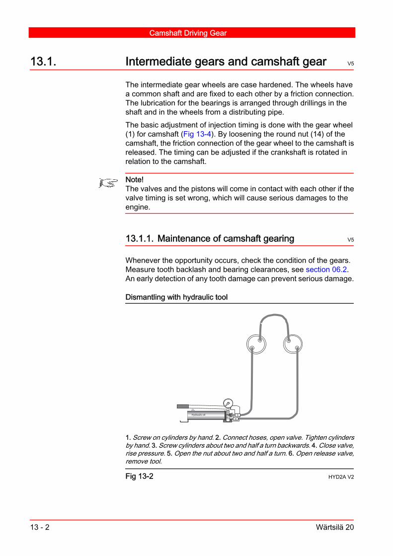
13.1. Intermediate gears and camshaft gear V5
The intermediate gear wheels are case hardened. The wheels havea common shaft and are fixed to each other by a friction connection.The lubrication for the bearings is arranged through drillings in theshaft and in the wheels from a distributing pipe.The basic adjustment of injection timing is done with the gear wheel(1) for camshaft (Fig 13-4). By loosening the round nut (14) of thecamshaft, the friction connection of the gear wheel to the camshaft isreleased. The timing can be adjusted if the crankshaft is rotated inrelation to the camshaft.
Note!The valves and the pistons will come in contact with each other if thevalve timing is set wrong, which will cause serious damages to theengine.
13.1.1. Maintenance of camshaft gearing V5
Whenever the opportunity occurs, check the condition of the gears.Measure tooth backlash and bearing clearances, see section 06.2.An early detection of any tooth damage can prevent serious damage.
Dismantling with hydraulic tool
Hydraulic oil
1. Screw on cylinders by hand. 2. Connect hoses, open valve. Tighten cylindersby hand. 3. Screw cylinders about two and half a turn backwards. 4. Close valve,rise pressure. 5. Open the nut about two and half a turn. 6. Open release valve,remove tool.
Fig 13-2 HYD2A V2
Camshaft Driving Gear
13 - 2 Wärtsilä 20

13.1.2. Basic adjustment of valve timing V7
Basic adjustment of the valve and injection timing is done by changingthe relative position of the camshaft and gearwheel (1). If the positionis changed, the position of the camshaft is changed in relation to thecrankshaft.
Note!The relative position between the camshaft and crankshaft is adjustedat the factory and should not be changed unless it is absolutely nec‐essary.
1 Remove the camshaft end cover (13).
2 Turn the crankshaft until the position of correct injection timing isreached.
Reassemble with hydraulic tool
Hydraulic oil
1. Screw on nuts, attach distance sleeve. Screw on cylinders to the bottom byhand.2. Connect hoses, open valve. Tighten by hand. 3. Close the valve andpump pressure to the stated value. 4. Screw the nuts until close contact to face.5. Open the valve and remove tool set.
Fig 13-3 HYD2A V2
3 Install the hydraulic tool 861169 on the screw (12).
4 Loosen the nut using correct hydraulic pressure and turn the crank‐shaft. The intermediate and camshaft gear wheel should then rotatewhile the camshaft should stand still. See, Chapter 07: Hydraulicallytightened connections.
5 Tighten the screw connection and re-check the injection timing. See,Chapter 16: Control of fuel injection timing.
6 Remove the hydraulic tool and install the camshaft end cover.
Camshaft Driving Gear
Wärtsilä 20 13 - 3

Note!The round nut (14) of the camshaft is guided against a shoulder in thegear wheel for governor drive (10). When tightening the camshaftscrew, pay close attention to fix the nut correctly against the guidingface in order to prevent damaging the parts.
Camshaft driving gear
1
2
A
3
4
5
6
7 8 9
10
11
12
13
14
15
16
17
18
19
20
21
1. Gear wheel for camshaft 2. Extension shaft 3. Intermediate gear wheel4. Bearing bush 5. Crankshaft 6. Gear wheel for crankshaft 7. Screw8. Screw 9. Housing 10. Gear wheel for governor drive 11. Extension shaft12. Screw 13. Cover 14. Screw 15. Guiding pin 16. Screw 17. Screw18. Shaft 19. Cover 20. Bearing bush 21. Intermediate gear wheel.A.Indicating mark
Fig 13-4 201353 V1
13.1.3. Removing of camshaft driving gear V5
1 Remove the gearing covers and the adjacent camshaft cover.
Camshaft Driving Gear
13 - 4 Wärtsilä 20

2 Turn the crankshaft to TDC at firing for cylinder No. 1.
Dismantling with hydraulic tool
Hydraulic oil
1. Screw on cylinders by hand. 2. Connect hoses, open valve. Tighten cylindersby hand. 3. Screw cylinders about two and half a turn backwards. 4. Close valve,rise pressure. 5. Open the nut about two and half a turn. 6. Open release valve,remove tool.
Fig 13-5 HYD2A V2
3 Remove the governor unit and speed pick-ups.
4 Remove the governor drive cover plate (13) . See Fig 13-4, and dis‐connect oil supply pipe.
5 Open the nut (14) and remove the drive gear for the governor (10).
6 Open the screws (7) and remove the complete governor drive as‐sembly.
7 Remove the end piece (11).
8 Remove the camshaft gear wheel (1).
9 Remove the intermediate gear wheel cover (19) and spray nozzles.
10 Remove the extension shaft (2).
11 Open the fastening screws (17) and remove the shaft piece (18) andthe small intermediate gear wheel (21).
12 Remove the big intermediate gear wheel (3).
Camshaft Driving Gear
Wärtsilä 20 13 - 5
13.1.4. Mounting of the camshaft gearing V7
Note!Turn the crankshaft to TDC at ignition for cylinder No.1 before pro‐ceeding with the job.
1 Lubricate the bearing bushes (4) and (20). See, Fig 13-4.
2 Lift the big intermediate gear wheel (3) into position.
3 Insert the small intermediate gear wheel (21) onto the collar of the bigintermediate gear wheel.
4 Insert the shaft piece (18) and hand tighten the fastening screws(17).
5 Insert the extension piece (2). Ensure that the indicating mark (Fig13-4) is visible and is in a horizontal position.
6 Lift the camshaft gear wheel (1) into position. Ensure that the cam‐shaft gear wheel is mounted with the deeper side towards the screwconnection.
7 Insert the end piece (11).
8 Insert the housing of the governor drive. Replace the O-ring with anew one and tighten the screws (7) to stated torque.
9 Insert the gear wheel for governor drive (10) and the screw (12) intoposition. Insert and hand tighten the nut (14).
Note!Insert the nut carefully onto the guiding collar in the gear wheel forthe governor drive before installing the hydraulic tool onto the screw.
10 Tighten the screw (17) for the intermediate gear wheel to stated tor‐que.
Camshaft Driving Gear
13 - 6 Wärtsilä 20

Reassembling with hydraulic tool
Hydraulic oil
1. Screw on nuts, attach distance sleeve. Screw on cylinders to the bottom byhand.2. Connect hoses, open valve. Tighten by hand. 3. Close the valve andpump pressure to the stated value. 4. Screw the nuts until close contact to face.5. Open the valve and remove tool set.
Fig 13-6 HYD2A V2
11 Lift the hydraulic tool onto the screw and rise the pressure to 300 barand tighten the nut.
12 Check the valve timing. See, section 16.2.6.
13 Tighten the nut to the full stated pressure. See, section 07.3.
14 Mount the governor unit and the speed pick-ups.
15 Install the covers for the gearing and the camshaft.
16 Mount all the covers and the oil pipes.
Note!Check the valve timing before the engine is started.
13.2. Crankshaft gear ring V2
The gear wheel ring (6) is press fitted to the crankshaft. Removingand mounting the gear ring requires special knowledge and shouldbe conducted by authorized personnel only.
Camshaft Driving Gear
Wärtsilä 20 13 - 7

Camshaft Driving Gear
13 - 8 Wärtsilä 20

14. Valve Mechanism and Camshaft V2
14.1. Valve mechanism V7
The valve mechanism transfers the cam motion to the valves. Thevalve mechanism consists of piston type valve tappets (2) moving ina common guide block casing; the multihousing (3), tubular push rods(6) with ball joints, nodular cast iron rocker arms (8) journalled on arocker arm bearing bracket (11), yokes (10) guided by a yoke pin inthe cylinder head.
Valve Mechanism and Camshaft
Wärtsilä 20 14 - 1

Valve mechanism
YX
1
2
3
4
5
6
7
9
8
1011
12
13
A
A
A - A
1. Roller pin, 2. Valve tappet, 3. Multihousing, 4. Cover for valve tappet, 5.Protecting sleeve, 6. Push rod, 7. Retainer ring, 8. Rocker arm, 9. Screw, 10.Valve yoke, 11. Rocker arm bracket, 12. Screw, 13. Securing screwX. Without floating bearing bush, Y. With floating bearing bush
Fig 14-1 201458 V2
14.2. Function of valve mechanism V3
The movement of the valve tappets is governed by the cam profile.The valve tappets transfer the movement through push rods to therocker arms. The rocker arms operate the inlet and exhaust valvesthrough a yoke.The bracket for the rocker arms is made of nodular cast iron and isfastened to the cylinder head by two long screws. The steel journal ispress fitted into the bracket. The positioning of the journal is importantfor the oil supply to the valve mechanism.
Valve Mechanism and Camshaft
14 - 2 Wärtsilä 20

The rocker arms act on the valve yokes, which are guided by an ec‐centrically placed yoke pin. To compensate for heat expansion aclearance must exist between the rocker arm and yoke. All adjust‐ments are made on a cold engine, and this work procedure is ex‐plained in chapter 12. Each valve yoke operates two valves simulta‐neously.The valve mechanism is lubricated from the main flow with pipe con‐nections. All other flows in the cylinder head are through drilled bores.Oil to the valve yokes passes through the rocker arm bracket in anintermittent flow controlled by the bore in the rocker arm. Oil will onlyflow through the rocker arm when it is in the open-valve position. Oilwhich is passed to the yoke lubricates the yoke tappet and by splash‐ing through the bores also lubricates the valve rotators. Oil is returnedto the crankcase in a free flow through the protective sleeves of thepush rod.
Note!The intermittent supply provides a minimal oil flow to the valve mech‐anism. The oil flow to a cylinder head with all valves closed is "shutoff". To completely check the oil flow to a cylinder head during prelubrication, the engine must be rotated during pre-lubrication.
14.3. Maintenance of valve mechanism V8
Normally, the valve mechanism need no maintenance, but the com‐ponents should be checked for damage and wear at the intervals sta‐ted in chapter 04. See chapter 06 for adjustments and wear limits. Ifthe valve mechanism is dismantled, the components should bemarked and later reassembled in the same position to avoid unnec‐essary wear.
14.3.1. Dismantling of valve mechanism V8
1 Remove the covers of the valve mechanism and camshaft from thecylinder concerned.
2 Turn the crankshaft to a position where the valve tappet rollers of thevalves and the injection pump are on the base circle of the cam.
3 Unscrew the screws (9) and remove the rocker arm bearing bracketfrom the cylinder head.
4 Remove the retainer rings and rocker arms. To remove the retainerrings, use pliers 843004.
Valve Mechanism and Camshaft
Wärtsilä 20 14 - 3

5 Remove the push rods injection pipe, fuel leak pipes and the protect‐ing sleeves.
6 Remove air pipe and lube oil pipes. Loosen the control shaft bracket.Disconnect the fuel rack.
7 Open the fuel pipe connection between the multi-housings con‐cerned. Use circlip pliers to slide the fuel retainer ring to one side.Move the fuel line connecting sleeves clear of the adjacent fuel pipes.
8 Loosen the fastening screws 12, remove the high pressure connect‐ing piece and protecting sleeve. Remove the housing (3).
9 Remove the securing plate. The valve tappets can now be withdrawn.Before dismantling, mark the parts so that they can be reassembledin their original positions.
10 The tappet roller and pin can now be separated by depressing theretainer into the pin and slide out. The tappet should be covered, asthe retainer is under spring loaded tension.
14.3.2. Inspection of valve mechanism parts V5
1 Clean the rocker arm bore and the journal and measure for wear.When cleaning, pay special attention to the oil holes.
2 Clean and inspect all parts of the valve tappet. When cleaning, payspecial attention to the oil holes.
3 Check for wear by measuring the tappet, the housing bore and theroller.
4 Change the O-rings of the cover (4) if they are damaged or hard.
14.3.3. Assembling the valve mechanism V9
1 Lubricate the parts of the valve tappet with clean engine oil and as‐semble. Observe the marks for correct positioning.
2 Insert the valve tappets into the multi-housing and mount the securingplate (13).
3 Mount the cover for valve tappet.
4 Mount the complete housing onto the engine and tighten the screwsto the stated torque according to Chapter 07: Tightening Torques andInstructions for Screw Connections.
5 Connect the fuel pipes between the multi-housings concerned. Movethe fuel line connecting sleeves on the adjacent fuel pipes. Use circlippliers to slide the fuel retainer ring into its groove.
Valve Mechanism and Camshaft
14 - 4 Wärtsilä 20

6 Connect the air pipe, injection pipe, fuel leak pipes and lube oilpipes. Mount the control shaft bracket and connect the fuel rack.
7 Grease the O-rings, insert the protecting sleeves (5) and push rods(6) into the guide block.
8 Mount the yoke. For adjusting the yokes, see section 12.2.5.
9 Lubricate the rocker arm bore and mount the rocker arms (8) on thebracket.
10 Apply the retainer rings (7) by using pliers 843 004. Check the axialclearance and free rotation of rocker arms.
11 Mount the rocker arm bracket on the cylinder head and tighten thescrews (9) to the stated torque. See, Chapter 07: Tightening torquesfor screws and nuts.
Note!The rocker arm bracket has to be centred.
12 Check the valve clearance according to Chapter 06: Adjustments.Mount the covers.
14.4. Camshaft V7
The camshaft is built up of one-cylinder camshaft pieces (1) and sep‐arate bearing pieces (2).The drop forged camshaft pieces have integrated cams, the slidingsurfaces of which are case hardened. The camshaft is driven by thecrankshaft through gears at the driving end of the engine. At this endthe camshaft is provided with a helical gear for driving the speed gov‐ernor.The camshaft has an axial bearing at the driving end. The oil supplyis arranged to the axial bearing from the driving end of the engine.The camshaft has a bore, through which oil is supplied to every cam‐shaft bearing and from there up to the multihousing. The rotationalspeed of the camshaft is only half of the engine speed.
Data and dimensionMaterial: Special steel,case hardenedWeight: Camshaft piece14,6 kgBearing piece 8,6 kg
Valve Mechanism and Camshaft
Wärtsilä 20 14 - 5

Camshaft
123
612 7 8
5
11
104
9
11
4
8
13
1. Camshaft piece, 2. Bearing piece, 3. Bearing piece, 4. Screw, 5. Extensionpiece, 6. Drive gear, 7. End piece, 8. Screw, 9. Nut, 10. Gear, 10. Guide flange(ProAct actuator), 11. Guide pin, 12. Cover, 13. Cover.
Fig 14-2 201459 V2
14.4.1. Removing of camshaft piece V9
1 Remove the camshaft covers. See Chapter 16. Remove the rockerarm brackets and the injection pumps for the cylinders concerned.Before removing the injection pumps remove the control shaft com‐pletely or support it well.
2 Remove the cover 12 from the free end of the camshaft. And also thecover 13 from the driving end of the camshaft, if necessary.
3 Loosen the nut of the screw 4 or 8 depending on the cylinder con‐cerned. Note the position of the camshaft piece, using the hydraulictools 861158 and 861169. See Chapter 07 for correct pressure.
Note!When undoing the camshaft connection the hydraulic jack has to beturned to the bottom, then undone for two and a half turns. The nut isto be undone opened for two and half turns and the pressure releasedslowly.
4 Separate the camshaft piece concerned from the bearing pieces byusing a suitable lever. Pay attention not to damage the tappet rollersor camshaft pieces when moving the shaft axially.
5 Remove the screw from the camshaft.
Valve Mechanism and Camshaft
14 - 6 Wärtsilä 20

6 Remove the camshaft piece carefully via the camshaft doors.
14.4.2. Mounting of camshaft piece V8
1 Clean and lubricate the camshaft bearing bush and the bearing sur‐face of the bearing piece with clean engine oil. Carefully insert thebearing piece into the bearing housing. Pay attention to the positionof the bearing piece.
2 Insert the guide pins into the bearing piece and fit the snap rings. Theshorter section of each pin should protrude from the bearing piece.Fig14-2
3 Install the camshaft piece between two bearing pieces and onto theguiding face of the bearing pieces. Check the position of the guidepins. Check the position of the guide pins. Insert the M42*3 screw andpre-tighten it by hand.
4 Move the camshaft pieces axially with a suitable lever. Hand tightenthe nut.
5 Check the injection timing prior to tightening the camshaft driving gearnut wheel to full torque. See Chapter 16
6 Install the hydraulic tool. Rise the pressure in two steps, first to 300bar and tighten the nut. Then tighten the nut to a pressure accordingto Chapter 7. See Fig 14.3. Note the clearance between the pressureplate and sensors.
Note!When tightening the camshaft connection keep the hydraulic jack tothe bottom.
7 Check the valve tappets and rollers carefully. Even slightly damagedtappet rollers have to be changed.
8 Mount the injection pumps, injection pipes and rocker arms.
9 Mount the covers.
10 Check the valve clearances. See section 12.2.5.
14.5. Camshaft bearings V7
When the camshaft has been removed, the inner diameter of thebearing bush can be measured in situ, by using a ball anvil microme‐ter. The maximum diameter is stated in section 06.2. If the maximum
Valve Mechanism and Camshaft
Wärtsilä 20 14 - 7

diameter for one camshaft bearing bush is exceeded, all camshaftbearing bushes should be replaced. A special tool is available for thispurpose, see Fig 14-3.
14.5.1. Changing of camshaft bearing bush V6
1 Lubricate the new bearing bush with clean oil on the outer surfaceand put it on the guide sleeve. The distinct mark must be positioneddownwards and towards the flywheel end.
Note!The bearing bush without the oil groove can be used only in the cam‐shaft bearing bore No.1.
2 Put the thrust discs (1 and 4) and the thrust screw in place. Nowtighten the nut by hand until the new bearing bush meets the old one.
3 Tighten the nut to press out the old bearing bush. Simultaneouslymount the new bearing bush in place.
4 Unscrew the nut and dismantle the tool.
Changing of camshaft bearing bush
9
3145 2
8
8
541 3
9
2
10
A
7
6
1. Thrust disc, 2. Nut, 3. Thrust screw, 4. Thrust disc, 5. Guide sleeve, 6. Oilhole, 7. Distinct mark, 8. Bearing bush, new, 9. Bearing bush, old, 10. Bore no.1A. Bearing bush
Fig 14-3 201455 V2
Valve Mechanism and Camshaft
14 - 8 Wärtsilä 20

14.5.2. Changing of camshaft bearing bush No.1 V6
1 Lubricate the new bearing bush with clean oil on the outer surfaceand put it on the guide sleeve. The distinct mark must be positioneddownwards and towards the flywheel end. See Fig 14-3.
2 Put the thrust discs (1 and 4) and the thrust screw in place. Nowtighten the nut by hand until the new bearing bush meets the old one.
3 Tighten the nut to press out the old bearing bush. Simultaneouslymount the new bearing bush in place.
4 Unscrew the nut and dismantle the tool.
Valve Mechanism and Camshaft
Wärtsilä 20 14 - 9

Valve Mechanism and Camshaft
14 - 10 Wärtsilä 20

15. Turbocharging and Air Cooling V1
15.1. Turbocharger V6
The turbocharger utilizes the energy of the engine exhaust gas to feedmore air to the engine, thereby offering advantages such as boostedengine power output and thriftier fuel consumption.The exhaust gas discharged from the cylinders of the engine are ledthrough the exhaust manifold into the turbocharger and acceleratedin the turbine housing before the passages of the turbine wheel. Theturbine rotates at a high speed and turns the compressor wheelmounted on the same shaft as the turbine wheel. The compressortakes air, often through a filter, from the engine surroundings andcompresses it to a higher pressure. A higher pressure results in ahigher density of the air which means that a larger amount of air isforced into the cylinder and correspondingly a larger amount of fuelcan be burnt. This increases the effective pressure during the com‐bustion and thus increases the output.During the compression of the air in the turbocharger, the air is heatedup mainly due to the compression and partly due to losses in thecompression work in the compressor. The hot and compressed airflows through an air cooler. When the air is cooled, the density of theair is further increased.The turbocharger can be divided into two basic sections: The turbinewheel that is driven by the exhaust gas and the compressor wheelwhich forces intake air through the air cooler and into the cylinder.The turbine wheel is of the radial turbine type, i.e. the gas enters theturbine axially and leaves it radially. The shaft connecting the turbinewheel to the compressor wheel is supported by two bearings betweenthe turbine and compressor wheel. The compressor is of radial type,i.e. air enters the turbine radially and leaves it axially.The bearings are lubricated with lubricating oil from the engine lubri‐cating system.The air outlet housing of the turbocharger is connected to the air ductof the engine through a piece of metal bellows (1), which allows ther‐mal expansion of the air duct. The air duct is designed to reduce thespeed of the air in an efficient way before it enters the air cooler. Theair duct is provided with guiding vanes for an equal distribution of airover the whole air cooler surface. The air duct is fixed in position tothe air cooler housing.
Data and dimensionsWeight (dry):- TPS 52 230 kgMaterial:- Casings: special castiron- Turbine: special heatresistance steel- Compressor: light metalalloy or titanium alloy- Bracket: cast iron
Turbocharging and Air Cooling
Wärtsilä 20 15 - 1

Caution!The surfaces of the turbocharger and the air duct are hot.
The exhaust pipes from the engine are also connected to the turbo‐charger through metal expansion bellows. The exhaust pipe after theturbocharger should be arranged according to the installation instruc‐tions.The turbocharger is equipped with cleaning devices for cleaning ofboth the compressor and the turbine by water injection.
Turbocharger and charge air cooler assembly
A - A
A
A
A
A
B
C
410
2
2
6
7
3
2
6
3
5
7
1
9
8
8
1
1.Bellows, 2.Air cooler,3.Bellows,4.Charge air pipe,5.Cover,6.Air inlet piece,7.Water connection,8.Drain pipe,9.Air box,10.DiffuserB.TC at the driving end (LD),C.TC at the free end (LF)
Fig 15-1 201571 V2
Turbocharging and Air Cooling
15 - 2 Wärtsilä 20

15.1.1. Turbocharger maintenance V7
Maintenance of the turbocharger is carried out according to the in‐structions of the turbocharger manufacturer. It is recommended to usethe service net of the engine manufacturer or the turbocharger man‐ufacturer.Normal overhauls can be carried out without removing the turbo‐charger from the engine. When dismantling, remove the protectingcovers . Loosen the exhaust inlet and outlet pipes.When reassembling, take care that all seals are intact. High temper‐ature resistant lubricants are used for exhaust pipe screws.
15.1.2. Water cleaning of the turbine V7
During operation, especially when running on heavy fuel, impuritiesin the exhaust gases sticks to the turbine wheel and other compo‐nents in the turbocharger exhaust side. A dirty turbine causes highertemperatures of the exhaust gas and higher stresses of the bearingsdue to imbalance.Practical experiences show that the deposits on the turbine side canbe reduced by periodic cleaning (washing) during operation and theoverhaul periods can be extended.During long time of operation, periodic water cleaning prevents thebuild-up of significant deposits on the turbine blades and nozzlevanes. This cleaning method does not work on very dirty turbineswhich have not been washed regularly.If the normal water cleaning of the turbine does not effect much onthe exhaust gas temperature level, hard deposits have probably beenbuilt up on the nozzle ring and the turbine blades in the turbochargerand they have to be cleaned mechanically. For that purpose the rotorand the nozzle ring have to be removed from the turbocharger.At water cleaning the water must be injected into the exhaust systemwith the engine running at reduced output (see 15.1.3, step 1). Thedisadvantages of reducing the output occasionally is not significantcompared with the advantages of cleaning. The necessary water flow is basically dependent upon the volume ofgas and its temperature. The flow should be adjusted so that the majorpart of the water is evaporated and escapes through the exhaust. Itis important that all of the water does not evaporate, since the clean‐ing effect is based upon the water solubility of the deposits and themechanical effect of the impact of the water drops. Additives or sol‐vents must not be used in the cleaning water. The use of salt wateris prohibited.
Turbocharging and Air Cooling
Wärtsilä 20 15 - 3

Water cleaning of the turbine
2
A B
1
1
3
4
1. Valve 2. Quick-coupling 3. Flow meter 4. Valve.A.TC at the driving end, B.TC at the free end
Fig 15-2 201570 V2
Every gas inlet of the charger is equipped with a washing nozzle. Thenozzles are all connected to a common water connection which hasa valve and a quick-coupling. The water flow is controlled by flowmeter (3) to a suitable value, see table below.
Table 15-1 Water cleaning of turbine
Turbocharger size Water flow (l/min)TPS 48 6TPS 52 8TPS 57 10
Cleaning should take place regularly according to chapter 04, Main‐tenance Schedule. Depending on the results obtained, the intervalbetween two washings may be increased or reduced.
Turbocharging and Air Cooling
15 - 4 Wärtsilä 20

15.1.3. Turbine cleaning procedure V8
The flow meter enables accurate control of the amount of water in‐jected. Before cleaning the turbine, it is advisable to record the belowparameters for later use to assess efficiency of the cleaning; recordingat two or three different loads will give a more accurate evaluationbasis for the influence of the washing. Charge air pressure Exhaust gas temperatures after the cylinders Exhaust gas temperatures before and after the turbocharger, pro‐
vided that measurement equipment is installed Turbocharger speed Engine load
Note!The charge air pressure is not allowed to drop below 0.2 bar duringthe entire washing procedure.
1 Stabilise the temperatures.a ) For constant speed operated engines run the engine at approx.
25-30% load for 10 minutes. Maintain this load during the entirewashing procedure. Recommended temperature before turbineshould remain between 400°C and 450°C.
b ) For variable speed operated engines run the engine at approx.10-15% load (465-530 rpm of nominal 1000 rpm) for 10 mi‐nutes. Maintain this load during the entire washing procedure.Recommended temperature before turbine should remain be‐tween 400°C and 450°C.
2 Open valve (1) to confirm free passage.
3 Connect the water hose to the quick coupling (2) as in Fig 15-2
4 Open the water supply valve (4) before the flow meter (3) and imme‐diately adjust the water flow according to the table shown above,wash 30 seconds. Stop washing by closing the valve (1).
Warning!Water injection time and the exhaust gas temperatures are to becarefully observed. Continuous (heavily exceeding 30 seconds) waterflow may cause a failure of the turbocharger. Too high exhaust gastemperatures (>450°C) may result in impermissible thermal stresses.
5 Run the engine for 10 minutes to stabilise the temperatures.
6 Open the 2-way valve and wash for another 30 seconds.
Turbocharging and Air Cooling
Wärtsilä 20 15 - 5

7 Run the engine for 10 minutes to stabilise the temperatures.
8 Repeat steps 6 and 7 once more. Washing water should now havebeen injected three times.a ) After the washing, run the engine for 10 minutes at least at
25-30% load to stabilise the temperatures. If three times washing is not sufficient to clean the turbine (based onthe operating parameters) it is recommended to further perform twoadditional washing sequences. Washing the turbine more than three times also indicates that it isadvisable to shorten the intervals between each cleaning occasion.
15.1.4. Water cleaning of the compressor V7
The compressor can be cleaned during operation by injecting water.The method is suitable if contamination is not too far advanced. If thedeposit is very heavy and hard, the compressor must be cleaned me‐chanically.The injected water does not act as a solvent. The cleaning effect isachieved by the physical impact of the drops on the deposit. It istherefore advisable to use clean water containing no additives eitherin the form of solvents or softening agents that could be precipitatedin the compressor and form a deposit.Regular cleaning of the compressor prevents or delays the formationof deposit but does not eliminate the need for normal overhauls, forwhich the turbocharger has to be completely dismantled.Through an inlet pipe, pressured air can enter the dosing vessel. Thewater is injected to the compressor through the pipe (4), see Fig15-3 or Fig 15-4 depending on the location of the turbocharger.The water must be injected while the engine is running and at thehighest possible load, that is, at a high compressor speed.For an efficient washing, it is important to inject all the water requiredwithin 4-10 seconds. This water quantity is 0.4 dm3.For water injection, the water should first be measured with the meas‐uring cup and the same measured water is pressurised later (for ex‐ample by charge air). Under no circumstances may the injection noz‐zle be connected to the water main flow through tap or a large tankbecause this would allow an uncontrolled quantity of water to enterthe turbocharger and the diesel engine.
Turbocharging and Air Cooling
15 - 6 Wärtsilä 20

Water cleaning of compressor, TC at the driving end
1
3
6
2
5
4
1. Cover 2. Valve 3. Knob 4. Water pipe 5. Water cup 6. Inlet pipe
Fig 15-3 201568 V2
Water cleaning of compressor, TC at the free end
1
3
2
4
1. Cover 2. Button 3. Knob 4. Water pipe
Fig 15-4 201558 V2
Note!Clean the compressor (air side) of the turbocharger at as high loadas possible (full rated load).
The cleaning device for the compressor is used as follows:
Turbocharging and Air Cooling
Wärtsilä 20 15 - 7

1 Record the charge air pressure, cylinder exhaust gas temperatures,charger speed, for later use to assess efficiency of the cleaning.
2 Loosen knob (3) and remove cover (1).
3 Fill the vessel with water up to 1 cm below the rim.
4 Re-fit cover (1) and tight screw knob (3).
5 Turn valve (2) or press button (2). This admits compressed air fromthe air receiver to the vessel and forces the water through a pipe (4)to the compressor.
6 Repeat the readings taken in step 1 to compare the efficiency of thewashing. The success of injection can be recognized by the changein charge air pressure and in the exhaust gas temperature.
Note!If the injection is not successful, it must not be repeated before tenminutes.
After injection, the engine should be run loaded for at least five mi‐nutes.
15.1.5. Operation with damaged turbocharger V7
In case of a serious breakdown of the turbocharger, if the situationdoes not allow the immediate repair or exchange of the turbocharger,the engine can temporarily be operated up to about 15% of the nom‐inal output of the engine with the blanking device fitted.
Caution!Blocking the rotor is not recommended as it blocks the flow path forthe exhaust gases. Remove the rotor cartridge completely, and fit theblanking device according to the instructions in the turbocharger man‐ual.
Caution!As the turbocharger is out of function, the thermal load on the enginecomponents increases. Therefore, observe the exhaust gas temper‐atures carefully during the operation with blanked turbocharger.
Note!The exhaust gas temperatures after the cylinder heads must not ex‐ceed 500°C.
If the engine is operated for longer periods with exhaust temperaturesclose to 500°C with the blanked turbocharger, there is a risk of pistonseizure. This is due to the hot temperatures internally the piston (cool‐
Turbocharging and Air Cooling
15 - 8 Wärtsilä 20

ing gallery) causing the lube oil forming deposits in the cooling gallery.This results in a poorer cooling effect with more thermal expansion ofthe piston, one of which in turn can lead to piston seizure.During operation, also follow closely that the lube oil temperature iskept at the level of normal operation.Also other engine components are exposed to the higher thermalloading.After the turbocharger rotor cartridge has been removed and theblanking device fitted according to the instructions in the turbochargermanual, proceed in the following way:
1 Remove air inlet piece (6) and disconnect the cables for sensors ofthe charge air inlet piece. See, Fig 15-1.
2 Make sure that the air entry into the engine is clean and that no foreignparticles can enter the air inlet passage.
3 When the engine is loaded follow carefully that the exhaust gas tem‐peratures do not exceed 500°C. It is to be noted that the exhaust gastemperatures will increase by time and that the operator should firstlet the temperatures be stabilized at a certain load before the load isincreased to the maximum allowable. The maximum allowable loadin any case is about 15% of the nominal output of the engine.The engine shall not be operated without the turbocharger in functionfor more than 100 hours. If the engine has been in operation with highthermal load it is recommended the engine supplier is contacted inorder to clarify the need for exchange of components and/or inspec‐tions.
15.2. Charge air cooler V9
The charge air cooler is mounted between the air duct and air inletpiece, see Fig 15-1.The cooler is of a tube type. The tubes are provided with thin fins toget a more efficient cooling of the air. The cooling water circulates inthe tubes, while the compressed air passes between the fins on theoutside of the tubes.The top of the air cooler acts as a venting of the air cooler water side.
Data and dimensionMaterial- Tubes: copper alloy- Water boxes: cast ironWeight : 160 kg (dry)Test pressure: 8 bar(water side)
Turbocharging and Air Cooling
Wärtsilä 20 15 - 9

15.2.1. Charge air cooler maintenance V8
1 Condensate from the air is drained through a small hole/pipe (8) atthe bottom of the air cooler, see Fig 15-1. Examine regularly that thedraining pipe is open by checking the air flow when running.
Warning!If water keeps on dripping or flowing from the draining pipe for a longerperiod (unless running all the time in conditions with very high hu‐midity) the cooler insert may be leaky and must be dismantled andpressure tested.
2 At longer stops, the cooler should be either completely filled or com‐pletely empty, as a half-filled cooler increases the risk of corrosion. Ifthere is a risk of sinking water level in the system when the engine isstopped, drain the cooler completely. Open the air vent screw to avoidvacuum when draining.
3 Clean and pressure test the cooler at intervals according to Chapter04: Maintenance Schedule. If the receiver temperature cannot be heldwithin stipulated values at full load.
4 Always when cleaning, check for corrosion.
15.2.2. Cleaning of charge air cooler air side V1
Cleaning of the air side should be done early enough to avoid formingof soot and oil on the fins, which form a hard deposit layer that isdifficult to remove, as well as a build-up of products that form sulphuricacid (condensation) when left on the fins and tubes for some time.Generally an increase of pressure drop (Δp) over the cooler with 100mmH2O compared with a new/clean cooler means that the coolerneeds cleaning. The pressure drop should be measured at 100% loador at least always at the same high load level.
15.2.2.1. Ultrasonic cleaning V1
Cleaning with ultrasonic equipment is recommended as it gives thebest cleaning result.
15.2.2.2. Chemical cleaning V1
We recommend chemical cleaning of the air side, while cooler is re‐moved, see section 15.2.3.
Turbocharging and Air Cooling
15 - 10 Wärtsilä 20

15.2.2.3. Recommended detergents V1
The instructions and handling guidelines provided by the manufac‐turer of the detergent in question should always be observed whenusing the chemical.
Recommended cleaning detergentsSupplier Product designationBasol Ltd. Basol 77Clensol Ltd. Industrial ClegrisDrew Ameroid Marine Division
Ashland Chemical Company
One Drew Plaza
Boonton, NJ 07005, USA
Ameroid ACC-9
Henkel KGaA
Düsseldorf
P3-Grato 90
Houseman Ltd
The Priory, Burnham
Slough SL1 7LS, UK
Cooltreat 651
Maritech AB
Box 143
S-29122 Kristianstad, Sweden
H.D. Powder
W.1.H.D.S. phenol
Nalco Chemical Company
One Nalco Centre
Naperville, Illinois
60566-1024 USA
Nalfleet ACC
Nalfleet Marine Chemicals
PO Box 11
Winnington Avenue, Northwich
Cheshire, CW8 4DX, UK
Nalfleet ACC
Vecom Holding BV
PO Box 27
3140 AA Maassluis, Holland
Vecom B-85
15.2.3. Cleaning of air cooler insert V9
Cleaning of the water and air side heat exchange surfaces is imper‐ative for a long and trouble free operation of the engine and must bedone at regular intervals.
Turbocharging and Air Cooling
Wärtsilä 20 15 - 11

1 Remove the shield plates.
2 Remove the water connection and pipes when the cooling water isdrained. Disconnect the cables for sensors of the charge air coolerassembly.
3 Apply the lifting tool 833002 and check location of the lifting eye bolt(LD/LF/4L/5L).
4 Loosen the fastening screws of the air inlet piece (1) from the engineblock. Observe that two screws are inside of the air inlet piece.
5 Remove the remaining cooler flange screws. On the LD-engine: Openthe cover (5) and remove the fastening screws of the air cooler insideof the air box (9), Fig 15-1.
6 Lift of the air cooler (3), air inlet piece (1) and water connection (2)assembly. On the LF-engine: The diffuser (4) may also be removedat the same time to make removal and mounting of the air cooler as‐sembly easier.
Lifting of the air cooler assembly
LD LF4L/5L
2
10
6
77
2
833 002 833 002
A B
C
1
22
3
3
4
A.TC at the driving end (LD), B.TC at the free end (LF), C.Location of the liftingeye bolt.1. Air inlet piece 2. Water connection 3. Air cooler 4. Diffuser
Fig 15-5 201572 V4
7 Remove the air inlet piece and water connection from the air cooler.
8 Clean the air side of the cooler by immersing it in a chemical cleaningbath for at least 24 hours. We recommend that cleaning tank shouldbe equipped with perforated pipes on the bottom for the best cleaningeffect, see Fig 15-6. During cleaning, steam or pressurized air should
Turbocharging and Air Cooling
15 - 12 Wärtsilä 20

be connected to the pipes to get a good circulation. When cleaning iscompleted, the cooler should be flushed by applying a powerful waterjet.
Note!If the water jet attacks the cooling tubes vertically, i.e. in parallel tothe fins, a pressure of 120 bar is suitable to be applied at a distanceof two meters from the fin surface.
Caution!Wrong use of water jet may cause damage to the fins, which resultsin an increased pressure drop over the air cooler.
9 Clean the water side by detaching the headers from the cooler bun‐dle. Immerse the tube bundle into a chemical cleaning bath for at least24 hours. Upon completion, follow the recommendations given for theair side.
10 Check the gaskets before reassembling the water connection.
11 Apply sealing compound to the sealing faces. See, section of thespare parts catalogue for charge air cooler assembly.
12 Mount the air cooler assembly on the engine.
13 Vent the cooler and check the tightness when starting up.
Air cooler cleaning tank
A
1
2
A.Steam of air1. Perforated pipes 2. Cooler insert
Fig 15-6 201565 V1
Turbocharging and Air Cooling
Wärtsilä 20 15 - 13

Turbocharging and Air Cooling
15 - 14 Wärtsilä 20

16. Injection System V3
16.1. Injection pump V8
The engine is fitted with one injection pump per cylinder. The injectionpump is located in a "multihousing". The multihousing incorporates: A housing for the injection pump element, A fuel supply channel along the whole engine, A fuel return channel from each injection pump, Guides for the valve tappets, A lubricating oil supply to the valve mechanism.The multi-housing concept permits a reliable and compact design. Iteliminates fuel and oil piping and generally simplifies maintenance.The injection pumps are one-cylinder pumps with built-in roller tap‐pets. The valve tappets are integrated in the same multihousing. Thereturn fuel is drained at atmospheric pressure, through the integratedchannel, back to the low pressure fuel circuit. .Each injection pump is equipped with an emergency stop cylinder thatis coupled to an electro-pneumatic overspeed prevention system.
16.1.1. Function of injection pump V10
The injection pump supplies pressurized fuel to the injection nozzle.It has a mechanism to regulate the fuel supply according to the enginespeed and load. The pumps are controlled by the governor.The plunger Fig 16-1, is pushed up by the camshaft via the roller tap‐pet and pulled back by the tappet spring, reciprocates in the elementon a predetermined stroke to feed fuel under pressure.The plunger also controls the amount of fuel injected by adjusting theposition of the helical edge relative to the discharge port. The plungerhas an obliquely cut groove (lead) on its side. When the plunger is atthe lowest position or bottom dead centre, fuel flows through the inletport into the element bore. Rotation of the camshaft moves the plung‐er up. When the top edge of the plunger step is lined up with the ports,the plunger begins to compress the fuel. As the plunger rises further,the helix is eventually exposed to the discharge ports and the pres‐surized fuel is delivered through the lead to the ports. When the helixis no longer exposed to the discharge port, the supply is cut off. By
Data and dimensionsMultihousing:- material: special castiron- weight: 25 kgInjection pump element:- weight: 4.5 kgInjection press: 1500 barPlunger: coatedDelivery valveopening press.: 22 ± 2 barConstant pressure valve,opens when the pressuredifference is: 120 ± 10 bar
Injection System
Wärtsilä 20 16 - 1

rotating the plunger, it is possible to alter the proportion of stroke dur‐ing which the helix is exposed to the port. Thus the amount of fueldelivered during each plunger stroke can be controlled. The length ofstroke during which fuel is delivered is called the effective stroke andis regulated by the fuel governor via the fuel racks. The fuel racks aremeshed with the control sleeve which in turn is attached to the plung‐er. A linear movement of the racks is thus converted to a rotation ofthe plunger.The element is of a mono-block design with integrated fuel deliveryvalve and constant pressure valve. The ports are of a special designto prevent cavitation.The delivery valve, provided at the top of the element, performs thefunction of discharging the pressurized fuel to the injection pipe. Thefuel compressed to a high pressure by the plunger forces the deliveryvalve to open. Once the effective stroke of the plunger ends, the de‐livery valve is brought back to its original position by the spring andblocks the fuel path, thereby preventing counter-flow of the fuel.After the effective stroke, the fuel is drawn back through the constantpressure valve from the high pressure injection pipe to instantly lowerthe residual pressure between the delivery valve and the nozzle. Thisdraw-back effect improves the termination of an injection on the noz‐zle and prevents after injection dripping, and improves injection reg‐ularity by preparing the line for the next injection.The multihousing is provided with two erosion plugs, which can easilybe replaced when necessary.
16.2. Maintenance of injection pump V8
We recommend that the engine is run with light fuel for 5 minutesbefore overhauling the injection pump. During maintenance utmostcleanliness must be observed. It is unnecessary to remove the controlshaft unless every injection pump is to be removed. When the injec‐tion pump is dismantled, the components should be marked so thatto avoid unnecessary wear, they can later be reassembled in thesame position.
16.2.1. Removal of injection pump V9
1 Shut off the fuel supply to the engine and stop the prelubricatingpump.
2 Remove the covers of the valve mechanism and camshaft from thecylinder concerned.
Injection System
16 - 2 Wärtsilä 20

3 Turn the crankshaft to a position where the valve tappet rollers of thevalves and the injection pump are on the base circle of the cam.
4 Remove the rocker arms block, pushrods and the protecting pipes.
5 Remove the injection, fuel leak and lube oil pipes where necessary.Disconnect the fuel rack if necessary remove control shaft.
6 Undo the fuel pipe connections between the multihousings con‐cerned. Use circlip pliers to slide the fuel retainer ring to one side.Move the fuel line connecting sleeves clear of the adjacent fuel pipes.See Fig 16-1.
7 Cover immediately all openings with tape or plugs to prevent dirt fromentering the system.
8 Loosen the flange nuts and lift off the pump.
9 Cover the bore in the engine block.
16.2.2. Mounting of injection pump V14
1 Check and clean the pump. Also clean the plane and the bores of theengine block.
2 Check the O-rings of the insert part and lubricate with vaseline orengine oil. Check that the fuel cam is not in the lifting position.
3 Fit the pump and tighten the screws for the flange to the stated tor‐que. See Chapter 07,Fig 07-4and Fig 07-5.
4 Remove tape and plugs from all openings. Check that the exhaustand inlet cams are not in the lifting position.
5 Fit the protecting pipes, push rods, rocker arms bracket and adjustthe valve clearances. See Chapter 12, Fig 12-7. Assemble necessarypipes.
6 Close the fuel pipe connections between the multihousings con‐cerned. Use circlip pliers to slide the fuel retainer ring.
7 Assemble the injection pipe and tighten nuts to rated torque. SeeChapter 07.
8 Check that the fuel rack moves freely.
9 Connect the fuel rack to the control shaft. Assemble the control shaftif removed.
10 Rotate the control shaft and check that all pumps follow the shaftmovement. Check the fuel rack position of all pumps, see Chapter 22.
11 Open fuel supply to the engine. Vent the fuel system according to theinstructions in Chapter 17. The injection pump is provided with aventing plug.
Injection System
Wärtsilä 20 16 - 3

12 Mount the covers.
Injection pump
B
B
10 A
16
17
3
11
7
5
8
9
2
15
19
12
14
4
206
1
18
13
21
1. Tappet pin. 2. Tappet. 3. Plug. 4. Retaining ring. 5. Sleeve. 6. O-ring.7. Spring. 8. Spring plate. 9. Fuel rack. 10. Fuel delivery valve/Constantpressure valve. 11. Pump element. 12. Screw. 13. Erosion plug. 14. Plung‐er. 15. Control sleeve. 16. Spring. 17. Pin. 18. Tappet roller. 19. Guidescrew. 20. Seal ring/O-ring. 21. Alternative Design.
Fig 16-1 201668 V2
16.2.3. Removal of injection pump element V10
Most maintenance operations can be done without removing the mul‐tihousing from the engine. We recommend that the engine is run withlight fuel for 5 minutes before overhauling the injection pump. Duringmaintenance utmost cleanliness must be observed.
Injection System
16 - 4 Wärtsilä 20

1 Shut off fuel supply to the engine and stop the prelubricating pump.Open the covers.
2 Remove the injection, fuel leak and lube oil pipes where necessary.Disconnect the fuel rack.
3 Cover immediately all openings with tape or plugs to prevent dirt fromentering the system.
4 Turn the crankshaft so that the injection pump tappet is in the bottomposition and the roller resting on the base circle of the cam.
5 Loosen the flange screws until they are free from the threads.
6 Mount the extracting tool 846022 so that the tool flange is against thescrew heads. Tighten the nut until the element is held by the tool.
7 Lift the pump element.
8 Remove the extracting tool.
9 Remove the plug and remove the fuel rack.
10 Remove the plunger by turning it about 90° using the tool 846023.
11 Cover the opening in the multihousing immediately with clean cloth.
Note!The delivery valve must only be serviced by authorized personnel.
16.2.4. Changing of plunger sealing rings V9
Note!The sealing rings must always be renewed if they are removed fromthe groove on the plunger.
1 Remove the old rings, by cutting them off without damaging theplunger surface.
2 Place the protecting sleeve (846026) on top of the plunger to coverthe sharp edges of the helix.
3 Lightly lubricate the protecting sleeve, O-ring, sealing ring and theplunger with light fuel oil.
Injection System
Wärtsilä 20 16 - 5

Sealing ring assembly and calibration of rings
846 028
846 027
846 026
20
846026. Protecting sleeve 846027. Application rod 846028. Calibrating sleeve20. O-ring / Seal ring
Fig 16-2 201669 V2
4 Push the O-ring with the application rod (846027) over the protectingsleeve, down along the plunger and place it by hand in the groove.
5 Push the sealing ring with the application rod over the protectingsleeve, down along the plunger and place it by hand in the groove.
6 Remove the protecting sleeve. Use the test sleeve (846028) to checkthat the seals are correctly fitted in the groove.
16.2.5. Mounting of injection pump element V9
1 Check and clean the element.
2 Fit new O-rings and lubricate.
3 Clean the housing. Pay special attention to the O-ring sealing surfa‐ces.
4 Insert the plunger. Control sleeve with the tool 846023.
5 Check that the control sleeve is in correct position. Mount the fuel rackand plug . Check that the fuel rack moves freely.
6 Assemble the element into the housing. Be careful when connectingthe plunger into the element.
7 Tighten the fastening screws diagonally in steps to the stated tor‐que. See, Chapter 07: Tightening torques and use of hydraulic tools.
Injection System
16 - 6 Wärtsilä 20

8 Check that the fuel rack moves freely.
9 Rotate the control shaft. Check that all pumps follow the shaft move‐ment and check the fuel rack positions of all pumps, see Chapter 22:Control mechanism.
10 Remove the protecting tapes or plugs. Connect the pipes and theinjection pipe. Tighten the nuts to torque.
11 Open the fuel supply to the engine. Vent the fuel system according tothe instructions in Chapter 17: Fuel system.
16.2.6. Control of fuel injection timing V10
For normal adjustment of injection timing the prelift can be measuredmechanically by a special tool 869001.Control of fuel injection timing is necessary only if major componentshave been changed, for example, the camshaft intermediate gear orone or more camshaft pieces.
1 Remove the camshaft cover at the cylinder in question.
2 Turn the crankshaft until the pump tappet roller is on the basic circleof the camshaft. Approximately 20° before the ignition TDC.
3 Mount the checking tool 869001 and adjust the dial indicator tool848041 to zero.
4 Turn the flywheel in the rotating direction until the tappet rises 7mm.
5 Read the flywheel position. If the position is according to test records,go to step 13.
6 Remove the camshaft end cover. Install the hydraulic tool 861169 onthe screw, see Chapter 13: Basic adjustment of valve timing.
7 Loosen the nut by using correct hydraulic pressure. See, Chapter 07:Hydraulically tightened connections and release the pressure.
8 Turn the flywheel to the correct position.
9 Tighten the screw connection.
10 Turn the crankshaft until the pump tappet is on the basic circle.
11 Adjust the gauge to zero.
12 Turn the flywheel in the rotating direction until the tappet lifts up to 7mm. Check the position of the flywheel.
13 Unmount the checking tool.
14 Reassemble the cover of the intermediate gears.
15 Reassemble the camshaft cover.
Injection System
Wärtsilä 20 16 - 7

Note!Changing of the camshaft gear position will affect all cylinders.
Checking of injection timing
1
2
3
5
4
1. Tappet roller 2. Tappet 3. Camshaft 4. Dial indicator 5. Injection timingtool
Fig 16-3 201663 V2
16.2.7. Injection pump overhaul V8
The multihousing should be removed from the engine and properlycleaned.
Note!The element cylinder, plunger and delivery valve assembly arematched and they must be kept together during the overhaul.
1 It is recommended that the pump is firmly held in a vice while it isbeing dismantled.
2 Remove the injection pump element. See, Chapter 16: Removal ofinjection pump element.
3 Renew sealing rings on the injection pump plunger. See, Chapter 16:Changing of plunger sealing rings.
4 Turn the pump up side down.
5 Support the roller tappet with the tool 846016 and unscrew the guidingscrew. See,Fig 16-1.
6 Release the spring tension and remove the tool.
Injection System
16 - 8 Wärtsilä 20
7 The roller tappet and the spring can now be removed.
8 Remove the spring plate and control sleeve.
9 Depress the roller pin locking pin and withdraw the roller pin. Coverthe locking pin as it is under spring loaded.
10 As the valve tappet is also fitted into the multihousing, we recommendthat it is checked at the same time.
11 Wash the components in absolutely clean diesel oil and lubricate theinternal parts with engine oil. Pay special attention to the grooves andbores for leak fuel and lubricating oil. Clean protective latex glovesshould be worn when handling components.
12 Normally, further dismantling is not necessary. Ensure that the com‐ponents from different pumps are not mixed together, where appro‐priate apply identifying marks. The components must be protectedagainst rust, and in particular, avoid touching the plunger runningsurfaces with bare fingers.
13 Lubricate the roller and roller pin before assembling them.
14 Renew the sealing ring. Insert the control sleeve and the spring plateinto the housing.
15 Lubricate the tappet roller. Assemble it into the housing together withthe spring.
16 Support the tappet roller with the tool 846016 by keeping the slot forguiding screw in the correct position.
17 Depress the tappet roller until the slot is aligned with the hole.
18 Screw in and tighten the guiding screw to stated torque. See, Chapter07: Tightening Torques and Instructions for Screw Connections.
19 Turn the pump and assemble the injection pump element. See, Chap‐ter 16: Mounting of injection pump element.
20 Unless the pump is immediately mounted on the engine, it must bewell oiled and protected by a plastic cover or similar. The fuel portsand injection line connection must always be protected by plugs ortape.
16.3. Injection line V8
The injection line consists of two parts, the connection piece, whichis screwed sideways into the nozzle holder, and the injection pipe.
Injection System
Wärtsilä 20 16 - 9

The connection piece seals with plain metallic surfaces which are tobe checked before mounting. Always tighten the connection piece tocorrect torque before mounting the injection pipe; even if only the in‐jection pipe has been removed, because the connection piece mayhave been inadvertently loosened when the pipe was unscrewed.The injection pipe is covered by a shield to protect the engine envi‐ronment from fuel leaks. The injection pipes are delivered completewith connection nuts assembled. When assembling the high pressurepipe, the connection piece should be held with a tool.Always tightenthe connections to the correct torque.Protect dismantled injection line components against dirt and rust.
16.3.1. Checking the tightening of injection pipeconnections V3
When a new or overhauled engine has been running for 50 hours andwhile the engine is hot, re-check the tightness of the fuel pipe con‐nections.
Warning!Fuel that leaks, spills or sprays onto hot surfaces can cause fires.
Warning!A high pressure fuel oil spray from any broken or leaking injection pipemay cause serious injuries.
Injection System
16 - 10 Wärtsilä 20

Tightening of injection pipe connections
1
2
806009
820008
1./2. Injection pipe cap nut, 806009. Crowfoot wrench, 820008. Torque wrench.
Fig 16-4 V1
1 Open and remove the Hot Box covers.
2 Tighten the cap nuts of injection pipe to specified torque. Use thecrowfoot wrench (806009) with a torque wrench (820008) and checkthe tightening of injection pipe cap nuts.
3 Repeat the above procedure with the remaining injection pipes.
4 Mount the Hot Box covers after checking the tightening of all injectionpipes.
5 Check for leaks after starting the engine.
16.4. Injection valve V8
The injection valve is centrally located in the cylinder head and in‐cludes the nozzle holder (6) and the nozzle (1), seeFig 16-5. The fuelenters the nozzle holder from the side through a connection piecescrewed into the nozzle holder.The nozzles receive high pressure fuel from the injection pipe andinject this fuel into the combustion chamber as a very fine spray. Thepressure at which the nozzle operates can be corrected by turningthe adjusting screw (8) in the injection valve.
Data and dimensionOrifices: 8 pcsOrifice dia.: 0.38 mmAngle: 148°Opening press: 450 bar
Injection System
Wärtsilä 20 16 - 11

Injection valve
9
811
1
2
3
4
5
6
712
13 1014
1. Nozzle, 2. Nozzle nut, 3. Dowel pin, 4. Push rod, 5. Spring, 6. Injection valvehousing, 7. Thrust bolt, 8. Adjusting screw, 9. Nut, 10. O-ring, 11. Protectingsleeve, 12. Connection piece, 13. O-ring, 14. Injection pipe
Fig 16-5 201665 V1
16.4.1. Removing of injection valve V12
1 Remove the cylinder head cover.
2 Remove the injection pipe.
3 Remove the rocker arms.
4 Unscrew the connection piece and loosen the protecting sleeve ifnecessary.
5 Remove the fastening nuts of the injection valve.
6 Lift out the injection valve by using tool 846024.
7 Protect the fuel inlet hole of the injection valve and the bore in thecylinder head.
Injection System
16 - 12 Wärtsilä 20

16.4.2. Overhauling of injection valve V13
1 Inspect the nozzle immediately after removing the injection valve fromthe engine. Carbon deposits (trumpets) may indicate that the nozzleis in poor condition, or the spring is broken. Clean outside of the noz‐zle with a brass wire brush. Don't use steel wire brush.
2 Check the function and condition of the nozzle, that is, the openingpressure and seat tightness. It is recommended to use a pneumaticfuel valve test pump (864012) in order to judge spray characteristicswith realistic pumping rates. It is recommended to use an oil mistseparator (864018) with the test device to avoid unnecessary healthhazards. Optionally a hand pump tester (864012) with an accumulatordevice can be used for checking the nozzle function and condition.
Note!The detailed instructions of using the pneumatic fuel valve test pump(864012) are delivered with the pump.
Caution!Use the injector testing device only in a well ventilated place, pref‐erably with a suction line close to the test device.
3 Put the holder tool for injection valve (846030) in a screw vice. Insertthe injection valve into the tool with nozzle downwards.
4 Remove the nozzle from the holder by turning the injection valvehousing counter-clockwise until the cap nut is loosen. Keep the nozzletogether with the holder body, don't let it follow up with the nut. If thereis coke between the nozzle and the nut, the dowel pins may breakand damage the nozzle. To avoid this, knock on the nozzle, using apiece of pipe to keep it towards the holder. Never knock directly onthe nozzle tip. Be careful not to drop the nozzle.
5 Check the nozzle needle movement which may vary as follows: needle completely free needle free to move within the normal lifting range needle is stickingThe needle must not be removed by force because this often resultsin complete jamming. Unless it can be easily removed, immerse thenozzle in lubricating oil and heat oil to 150 - 200°C. Normally, theneedle can be removed from a hot nozzle.
Injection System
Wärtsilä 20 16 - 13

Maximum needle lift of nozzle, removing of nozzle from holder
B
A
A.Nozzle needle lift,B.Accepted wear for the sealing face of nozzle holder
Fig 16-6 201666 V1
6 Clean the components. If possible, use a chemical carbon dissolvingsolution. If there is no such available, immerse the details in clean fueloil, white spirit or similar to soak carbon. Then clean the componentscarefully by tools included in the tool set. Do not use steel wire brush‐es or hard tools. Clean the nozzle orifices with needles provided forthis purpose. After cleaning, rinse the details to remove carbon resi‐dues and dirt particles. Before inserting the needle in the nozzle body,immerse the components in clean fuel oil or special oil for injectionsystems. Seat surfaces, sliding surfaces (needle shaft) and sealingfaces against the nozzle holder should be carefully checked.
7 Clean the nozzle holder and the cap nut carefully. If necessary, dis‐mantle the nozzle holder to clean all details. Check the nozzle spring.
8 Check the high pressure sealing faces of the nozzle holder. That is,the contact face to nozzle and the bottom of the fuel inlet hole.
9 Check maximum needle lift of nozzle, that is, sum of measures A andB. If the wear B exceeds 0.10 mm, the nozzle holder can be sent tothe engine manufacturer for reconditioning. If nozzle needle lift is outof the value stated in Chapter 06: Clearances and wear limits (at20°C), the nozzle should be replaced by a new one
10 Reassemble the injection valve. Tighten the cap nut to the torquegiven in Chapter 07: Tightening torques for screws and nuts.
Injection System
16 - 14 Wärtsilä 20

11 Connect the injection valve to the test pump 864012 . Use connectionpiece 167003 from the engine to connect injection valve to the testpump. Pump to expel air. Shut the manometer valve and pump rapidlyto blow dirt out of the nozzle orifices. Place a dry paper under thenozzle and give the pump a quick blow. Note fuel spray uniformity.
Note!Ensure hands are not in the path of the spray jets.
12 Check the opening pressure: open manometer valve, pump slowly and watch manometer to note the opening pressure. if the opening pressure is not rising to the stated pressure then
adjust by turning the adjusting screw clockwise.
Adjusting of opening pressure
8
9
8.Adjusting screw 9.Nut
Fig 16-7 V1
13 Place a dry paper under the nozzle and give the pump a quickblow. Note fuel spray uniformity. If the spray is uniform, adjust theopening pressure to the stated value and check once more the sprayuniformity.
Injection System
Wärtsilä 20 16 - 15

14 Check the needle seat tightness: increase pressure to a value 20 bar below the stated opening
pressure, keep pressure constant for 10 seconds and check that no fuel
drops occur on the nozzle tip. A slight dampness may be accept‐able.
15 Check the needle spindle tightness: pump until pressure is 20 bar below the stated opening pressure, measure time for a pressure drop of 50 bar. If the time is below 3
seconds, it indicates worn nozzle and it must be replaced by a newone. A time longer than 20 seconds indicates fouled needle, andthe nozzle must be cleaned.
16 If the tests according to step 10 to 14 give satisfactory results theinjection valve can be re-installed in the engine. Otherwise, replacethe nozzle by a new one.
17 If leakage occurs on the high pressure sealing surfaces, the damagedpart should be replaced by a new one or reconditioned.
18 If nozzles or injection valves are to be stored, they should be treatedwith corrosion protecting oil. The nozzle and fuel connection must beprotected by plugs or tape.
16.4.3. Mounting of injection valve V9
1 Check that the bottom surface of the bore in the cylinder head isclean. If necessary, clean or lap the surface by the tool 841020. Iflapping is necessary, the cylinder head must be lifted off. For lapping,a steel washer and fine lapping compound is used. The injection valveseals directly to the bottom of the cylinder head bore.
2 Put new O-rings on the injection valve. Lubricate the injection valvewith engine oil or vaseline.
3 Fit the injection valve into the cylinder head bore but do not tightenthe nuts.
4 If the protection piece has been removed, fit new O-rings onto boththe protection piece and the connection piece . Mount the protectionpiece onto the connection piece.
5 Screw in the protecting sleeve on the connection piece if it has beenremoved. Screw in the connection piece by hand. Tighten to correcttorque. Tighten the protecting sleeve screws.
6 Mount the injection pipe and tighten the cap nuts to torque.
Injection System
16 - 16 Wärtsilä 20

7 Before tightening the fastening nuts of the injection valve, let the valveto stay in the cylinder head bore for 30 minutes to allow the temper‐atures to equalize.
8 Finally tighten the nuts with using a torque wrench in the followingsteps: a Both nuts to 20 Nmb Both nuts to 30 Nmc Both nuts to 40 Nmd Both nuts to final torque 50±3 Nm
9 Mount the rocker arms.
10 Mount the covers.
16.5. Pneumatic overspeed trip device V9
The pneumatic overspeed trip device is mounted on the multihousingand acts directly on the fuel rack. If the overspeed trip device is acti‐vated, pressurised air acts on a piston in a cylinder mounted on themultihousing. The piston forces the fuel rack to a "no fuel" position.The force of the overspeed trip device is stronger than the torsionspring in the regulating mechanism. For maintenance of the pneu‐matic overspeed trip device, see section 22.4.
Pneumatic overspeed trip device
3
21
4
1. Cylinder, 2. Piston, 3. O-ring, 4. Fuel rack
Fig 16-8 201662 V1
Injection System
Wärtsilä 20 16 - 17

Injection System
16 - 18 Wärtsilä 20

17. Fuel System V6
The engine is designed for continuous heavy fuel duty. The main en‐gine as well as the auxiliary engine can be started and stopped onheavy fuel provided that the fuel is heated to operating temperatureand the jacket water preheated to described temperature.As the fuel treatment system before the engine can vary widely fromone installation to another, this system is not described in detail in thismanual. See separate instructions. Normally a fuel feed pump deliv‐ers the correct flow to the engine through a filter. The correct pressurein the engine system is maintained with an adjustable throttle valve.It is of great importance that the fuel treatment before the engine isdone properly. The filtration of the fuel directly influences on the life‐time of the injection pumps and other components in the injection lineand hence the performance of the engine.
Fuel system
3 0 4 003 0 4 00
FUEL OIL
101102103
5 2
3
4 1
1.Adjustable orifice 2.Pressure switch 3.Pressure gauge 4.Alarm for broken in‐jection pipe 5.Damper 101.Fuel inlet 102.Fuel return 103.Leak fuel drain, cleanfuel.
Fig 17-1 201752 V2
A pressure gauge (3) on the instrument panel indicates the fuel inletpressure. A pressure switch (2) for low fuel pressure is connected tothe automatic alarm system.
Fuel System
Wärtsilä 20 17 - 1

Fuel leaking from injection pumps and injection valves is collected ina separate enclosed system. Thus this fuel can be reused. A specialmodule for automatic handling of this fuel back to the system can bedelivered on request.A separate pipe system leading from the top level of the engine blockcollects waste oil, fuel and water arising, for example, when over‐hauling cylinder heads.The high pressure system, with injection pump and injection valve, isdescribed in chapter 16.
17.1. Fuel oil safety filter V2
During the first start up of the installation, a fuel oil safety filter (run‐ning-in filter) should be installed in the fuel system just before theengine. The purpose with this filter is to protect the fuel system duringthe first running hours. This filter should be used for max 50 h.If the fuel system before the engine is opened later, it is recommendedthat this filter is used for a few hours again.
17.2. Fuel system maintenance V6
When working with the fuel system, always observe utmost cleanli‐ness. Pipes, tanks and the fuel treatment equipment, such as pumps,filters, heaters and viscosimeters, included in the engine deliveryshould be carefully cleaned before use.The fuel should always be separated. It is recommended to fit an au‐tomatic filter in the fuel treatment system.Always vent the system after reassembly, see section 17.3.For maintenance of the fuel treatment equipment not mounted on theengine, see separate instructions.
17.3. Venting the system V6
Open the air vent screws on the injection pumps. Start the fuel feedpump if the static pressure from the day tank is not sufficient.Always vent the filters after changing cartridges in the filter.
Fuel System
17 - 2 Wärtsilä 20

18. Lubricating Oil System V9
Normally, a wet sump system is used, but also dry sump systems canbe used.The engine is provided with a lubricating oil pump (3) directly drivenby the pump gear at the free end of the crankshaft. It is possible toconnect an electrically driven stand-by pump in parallel if needed. Thepump sucks oil from the engine oil sump and forces it through thelubricating oil cooler (6) equipped with a thermostat valve (5) regu‐lating the oil temperature, through the lubricating oil main filter (7) tothe main distributing channel in the engine block, and via side screwbores to the main bearings.
Lube oil system
1
2
4
3
5
a
6
7
9
11
12
8
14 1310
1. Centrifugal filter, 2. Prelubricating oil pump, 3. Lube oil pump, 4. Pressureregulating valve, 5. Thermostatic valve, 6. Lube oil cooler, 7. Lube oil filter, 8.Pressure gauge, 9. Oil dipstick, 10. Camshaft bearings, 11. Gudgeon pins, 12.Rocker arm bearings, 13. Lube oil pipe to T/C, 14. Lube oil pipe from T/C, a. Ifdry sump.
Fig 18-1 201863 V1
Lubricating Oil System
Wärtsilä 20 18 - 1

Part of the oil flows through the bores in the crankshaft to the big endbearings and further through the connecting rod to the gudgeon pins(11), piston skirt lubricating and piston cooling spaces. Oil is ledthrough separate pipes to other lubricating points, like camshaft bear‐ings (10), fuel pump and valve tappets and valves, rocker arm bear‐ings (12) and valve mechanism gear wheel bearings, and to oil noz‐zles for lubricating and cooling.The electrically driven prelubricating pump is a gear type pump equip‐ped with an overflow valve. The pump is connected in parallel to theengine driven lubricating oil pump.The pump is used for: filling of the diesel engine lubricating oil system before starting,
e.g. when the engine has been out of operation for a long time, continuous prelubrication of a stopped diesel engine through
which fuel oil is circulating, continuous prelubrication of stopped diesel engine(s) in a multi-
engine installation always when one of the engines is running.The pressure in the distributing pipe is regulated by a pressure controlvalve (4) on the pump. The pressure can be adjusted by means of aset screw on the control valve. It is very important to keep the correctpressure in order to provide efficient lubrication of bearings and cool‐ing of pistons. Normally, the pressure stays constant after havingbeen adjusted to the correct value.The pressure can rise above the nominal value when starting withcold oil but will return to the normal value when the oil is heated. Apressure gauge (8) on the instrument panel indicates the lubricatingoil pressure before the engine (in the engine distributing pipe). Thesystem includes three pressure switches for low lubricating oil pres‐sure, two connected to the automatic alarm system and one for lowerpressure to the automatic stop system (see chapter chapter 23, sec‐tion 23.1).The temperature can be checked from thermometers before and afterthe oil cooler (chapter 01., section 01.2). A temperature switch for highlubricating oil temperature is connected to the automatic alarm sys‐tem (see chapter chapter 23, section 23.1).The speed governor has its own oil systems, see separate instructionbooks.The oil filling opening and oil dipstick (9) is located at the middle ofthe engine.Connections for a separator are provided on the oil sump at the freeend of the engine.
Lubricating Oil System
18 - 2 Wärtsilä 20
18.1. Maintenance of oil system V4
Use only high quality oils approved by the engine manufacturer ac‐cording to chapter 02, 02B.1.Always maintain sufficient quantity of oil in the system. The oil dipstickindicates the maximum and minimum limits between which the oillevel may vary. Keep the oil level near the maximum mark and neverallow the level to go below the minimum mark. The limits apply to theoil level in a running engine. Add maximum 10% new oil at a time (seechapter 02, 02B.1). One side of the dipstick is graduated in centime‐ters. This scale can be used when checking the lubricating oil con‐sumption.Change oil regularly at intervals determined in maintenance schedulefrom the installation concerned, see chapter 04 and 02, section02.2.2. While the oil is still warm, drain the oil system, as well as theoil cooler and filter. Clean the crankcase and the oil sump with properrags (not cotton waste). Clean the main filter and the centrifugal filter.Centrifuging of the oil is recommended, especially when using heavyfuels, see chapter 02, section 02.2.2.
Caution!Utmost cleanliness should be observed when treating the lubricatingoil system. Dirt, metal particles and similar may cause serious bearingdamage. When dismantling pipes or details from the system, coverall openings with blank gaskets, tape or clean rags. When storing andtransporting oil, take care to prevent dirt and foreign matters from en‐tering the oil. When refilling oil, use a screen.
18.2. Lubricating oil pump V6
Lubricating oil pump is a gear type pump. The pump housing has anintegrated pressure regulating/safety valve. Five identical sleevebearings are used. External lubrication is not required. The cover issealed with a glue compound.
Lubricating Oil System
Wärtsilä 20 18 - 3

Lube oil pump
A-A
8,9L20
4,5,6L20
A
A
33
3
1
2
3
3
4
3
1
6
9
9
7
8
2
3
3
4
5
1. Drive gear 2. Frictional rings 3. Screw 4. Pressure plate 5. Bearingslubrication grooves 6. Spacer 7. Sleeve 8. Sleeve 9. Bearing bush.
Fig 18-2 201864 V2
18.2.1. Removing of lubricating oil pump V5
1 Drain the oil sump.
Lubricating Oil System
18 - 4 Wärtsilä 20
2 Remove the suction pipe connection between the oil sump and thelubricating oil pump.
3 Remove the oil pump connection and fastening screws of the lubri‐cating pump.
4 Remove the lubricating oil pump using extraction screws.
5 Protect connections with suitable plugs, clean plastic or similar ma‐terial.
Lubricating Oil System
Wärtsilä 20 18 - 5

Lube oil pump
A-A
8,9L20
4,5,6L20
A
A
33
3
1
2
3
3
4
3
1
6
9
9
7
8
2
3
3
4
5
1. Drive gear 2. Frictional rings 3. Screw 4. Pressure plate 5. Bearingslubrication grooves 6. Spacer 7. Sleeve 8. Sleeve 9. Bearing bush.
Fig 18-3 201864 V2
Lubricating Oil System
18 - 6 Wärtsilä 20

18.2.2. Dismantling of lubricating oil pump V5
1 Remove and inspect the regulating valve. See, chapter 18: Lubricat‐ing oil pressure, regulating valve and safety valve.
2 Remove the pressure plate (4) by loosening the fastening screws(3).
3 Pull out the gear wheel (1) without using any tool. If the gear wheeldoes not come loose, a few strokes with a non-recoiling hammer willhelp. (The friction ring elements come loose together with the gearwheel).
Warning!Using an extractor may damage the shaft (axial scratches).
18.2.3. Inspecting the lubricating oil pump V5
1 Check all parts for wear and replace worn parts. See, chapter 06:Clearances and wear limits at 20°C.
2 Remove worn bearings with a suitable mandrel from the cover bymachining.
3 Mount new bearings (freezing is recommended) so that the bearingsare 3 mm below the sleeve and housing level. Ensure that the bearinglubrication grooves (5) slide into the right position. See, Fig 18-3.
4 Check the bearing diameter after mounting. Check the gear wheelaxial clearance, See chapter 06: Clearances and wear limits (at20°C).
18.2.4. Assembling the lubricating oil pump V6
1 Clean all the details carefully before assembling.
2 Clean and oil all the contact surfaces before installing the gearwheel.
3 Reinstall the friction ring elements (3).
Note!Reinstall the friction ring elements exactly as shown in below figure.The friction ring elements should fall easily in place and must not jam.
Lubricating Oil System
Wärtsilä 20 18 - 7

Mounting the gear wheel
4
3
2
1
1. Pressure plate 2. Screw 3. Frictional rings 4. Drive gear.
Fig 18-4 201855 V3
4 Reinstall the pressure plate.
5 Tighten the screws a little and check that the gear wheel is in the rightposition.
6 Tighten the screws to torque. See,chapter 07.
7 If the gear wheel (4) has been changed, check the backlash afterremoving the cover.
8 Mount the pump covers.
Note!After applying the sealant to the housing, the sleeves (7,8), see Fig18-3 must be pressed along with the cover for the last 5 mm of as‐sembly.
9 Mount the pipes.
18.2.5. Mounting of lubricating oil pump V3
1 Clean all sealing surfaces carefully and apply sealing compound tothe sealing faces.
2 Mount the lubricating oil pump.
3 Mount the suction pipe connection between the oil sump and the lu‐bricating oil pump.
4 Mount the oil pump connection.
5 Tighten all fastening screws to stated torque, see chapter 07.
6 Connect all necessary pipe connections.
Lubricating Oil System
18 - 8 Wärtsilä 20

18.3. Lubricating oil pressure regulating valveand safety valve V4
The pressure regulating valve, is integrated in the lubricating oil pumphouse and regulates the oil pressure before the engine by returningthe surplus oil direct from the pressure side of the pump to the crank‐case.
Pressure regulating valve
X1
2
3
4
5
6
X X
1.Ball for safety valve,2.Sealing ring,3.Regulating piston,4. Spring,5.Springholder, 6. Adjusting screw
Fig 18-5 201876 V2
A pipe is connected to the engine distributing channel, where thepressure is kept constant if the engine is running at constant speed.This pressure actuates the regulating piston (3) and the spring (4) istensioned to balance this force at the required pressure. Thus thepressure is kept constant in the distributing channel, irrespective ofthe pressure in the pressure side of the pump and of the pressuredrop in the system. By tensioning the spring a higher oil pressure isobtained (if too low).If, for some reason, the pressure should increase strongly in the pres‐sure pipe, e.g. due to clogged system, the ball (1) will open and admitoil to pass to the regulating piston (3). This serves as a safety valve.
18.3.1. Maintenance of the valves V5
1 Dismantle all moving parts. Check them for wear and replace worn ordamaged parts by new ones.
2 Clean the valve carefully.
3 Check that no details are jamming while reassembling and with theoil pump cover mounted to the pump housing.
Lubricating Oil System
Wärtsilä 20 18 - 9

18.3.2. Adjusting of the lubricating oil pressure V4
1 Loosen the counter nut on the adjusting screw.
2 Slowly turn the adjustment screw (6) until the pressure reaches thevalue mentioned in chapter 01, section 01.1., (can be seen from theengine's local pressure gauge).
3 Tighten the counter nut.
4 Check the pressure.
18.4. Lubricating oil cooler V5
The cooler is of the brazed plate type. The plate cooler consists of anumber of heat transfer plates brazed together into one unit with noseals.
Lube oil cooler
C
A B
7
4
5
5
4
1 1
332
2
2
6
7 6
1.Plate heat exchanger, 2.Automatic filter, 3.Oil module, 4.Cover for LT-watertherm. valve, 5.Cover for lube oil therm. valve, 6.Drain plug for oil, 7.Drain plugfor LT-water.A. TC at the driving end, B. TC at the free end, C. Viewed from underside.
Fig 18-6 201873 V2
Lubricating Oil System
18 - 10 Wärtsilä 20

18.4.1. Maintenance of lubricating oil cooler V5
1 Clean and test the cooler by hydraulic pressure. Follow the intervalsgiven in chapter 04. Cleaning is also needed if the lubricating oil tem‐perature tends to rise abnormally.
2 Clean the water side by removing the cooler from the engine.
3 Always when cleaning, check for corrosion and test by hydraulic pres‐sure.
Caution!If water leakage to the lubricating oil is suspected, the heat exchangermust be pressure tested and/or changed.
18.4.2. Disassembling and assembling of cooler
18.4.2.1. Disassembling of cooler V6
1 Open the drain valve.
2 Drain the oil module.
Caution!Be careful when removing the plate heat exchanger! Despite thedraining there will always be left a small amount of lube oil and water.
3 Drain the water side as much as necessary.
4 Remove the heat shield and pipes, if necessary.
5 Loosen the plate heat exchanger fastening screws.
6 Remove the plate heat exchanger from the oil module.
18.4.2.2. Assembling of cooler V6
1 Check cleanliness and scratches on all sealing surfaces.
2 Mount the O-rings on the oil module. Always use new O-rings.
3 Mount the plate heat exchanger on the oil module.
4 Tighten the plate heat exchanger fastening screws.
5 Reinstall the heat shield and pipes, if necessary.
Lubricating Oil System
Wärtsilä 20 18 - 11

18.4.3. Cleaning of oil side V4
Fouling of the oil side is normally insignificant. On the other hand,possible fouling will influence the cooler efficiency very strongly.Due to the design, the heat exchanger cannot be cleaned mechani‐cally from the inside. Slight fouling can be removed by blowing steamthrough the oil connection of the heat exchanger.If the amount of dirt is considerable, use chemical cleaning solutionsavailable on the market:Alkaline degreasing agents:Suitable for normal degreasing, however, not effective for heavygreases, sludge and oil coke. Requires high temperature. Alwayspour degreasing agent slowly into hot water, never the contrary. Rinsecarefully with water after treatment.Hydrocarbon solvents:Include the whole range from light petroleum solutions to chlorinatedhydrocarbons, e.g. thrichlorethylene. These products should be han‐dled with care as they are often extremely volatile, toxic and/or nar‐cotic.Solvent emulsions:Heavy fouling, e.g. oil coke, can often be dissolved only by usingthese solutions. Several brands are available on the market.
Note!Follow the manufacturer's instructions to achieve the best results.
18.4.4. Cleaning of water side V6
The cleaning should be carried out so that it does not damage thenatural protective layer on the heat exchanger. A tool has been de‐veloped for this purpose, see Fig 18-7.If the deposit in the plates is hard, e.g. calcium carbonate, it can beremoved chemically by using commercial agents. After this treatmentthe heat exchanger should be rinsed and, if necessary, treated witha solution neutralising the residual washing agents. Otherwise, followthe manufacturer's instructions.
Lubricating Oil System
18 - 12 Wärtsilä 20

18.4.4.1. Cleaning the plate heat exchanger V3
Cleaning method for plate heat exchanger, 845 005
1
2
3
4
5
1. Circulating water pump (845 006) 2. Lifting bracket (845 007) 3. Joint flange(845 009) 4. Hexagon socket screw 5. Plate heat exchanger
Fig 18-7 V1
1 Fit the lifting brackets.
2 Remove the screws that fasten the plate heat exchanger. Pull theplate heat exchanger onto the lifting brackets.
3 Connect the circulating water pump to the plate heat exchanger withthe joint flanges.
4 Circulate cleaning fluid through the plate heat exchanger until it isclean.
5 After cleaning.a ) Circulate fresh oil through the plate heat exchanger.
b ) Test at a pressure of 8 bar and reassemble.
18.5. Thermostatic valve V4
The oil system is provided with a fixed thermostatic valve fitted in thelube oil module.
Lubricating Oil System
Wärtsilä 20 18 - 13

Thermostatic valve for oil system
A-AA A
A A
B
C
6
1 2
45
7
2
3
12
3
1.Lubricating oil module,2.Cover,3.Drain plug,4.Screw (M6),5.Holder,6.O-ring,7.ElementA-A.Section,B.Viewed from underside TC at the driving end,C.Viewed from un‐derside TC at the free end
Fig 18-8 201874 V1
The Fig 18-9 shows the valve in a closed position (right). When thetemperature exceeds the nominal value, the contents of the elementsexpands and forces the valve unit towards the seat, thus passing partof the oil through the cooler. This movement continues until the righttemperature of the mixed oil is obtained. If the cooler becomes dirty,the temperature will rise a few degrees, which is quite normal, be‐cause the valve needs a certain temperature rise for a certain openingto increase the oil flow through the cooler.
Lubricating Oil System
18 - 14 Wärtsilä 20

Oil flow in temperature control valve
1 2
D D
B
A A
C
A.From pump,B.From cooler,C.To cooler,D.To engine1.Warm oil,2.Cold oil
Fig 18-9 201868 V1
18.5.1. Maintaining the thermostatic valve V6
Normally, no service is required. A very low or very high oil temper‐ature may depend on a defective thermostat. However, in the most ofthe cases, when the temperature is too high it depends on a dirtycooler.
1 Drain the oil module.
2 Remove the cover (2), the holder of the element (5), and then thethermostatic element. Use screws (M8) for extracting the holder of theelement.
Lubricating Oil System
Wärtsilä 20 18 - 15

Extracting of the thermostatic element
1
1. M8*>=25mm.
Fig 18-10 201877 V4
3 Check the element by heating it slowly in water. Check at which tem‐peratures the element starts opening and is fully open. The valuescan be found on the thermostatic element or in chapter 01, the lowervalue of the lube oil temperature is the opening temperature and thehigher value is for the fully open valve.
4 Change the defective element. Check O-rings and change, if neces‐sary. Apply sealing compound to the sealing faces between the cover(2) and the oil module.
18.6. Centrifugal filter V5
A centrifugal filter is mounted in the flush oil line from the automaticfilter. The purpose of the centrifugal filter is to remove the particlesfrom the oil that has flushed the automatic filter.The filter comprises a body (1) containing a cover (2) on which a dy‐namically balanced rotor assembly (3) is free to rotate. The rotor as‐sembly rotates when oil from the jet pipe hits the rotor wheel.
Lubricating Oil System
18 - 16 Wärtsilä 20

Centrifugal filter
B
A
6
7
5
1
3
2
4
8
9
1.Filter body assembly,2.Filter cover assembly,3.Rotor assembly,4.Bandclamp,5.O-ring,6.Safety ring,7.Screw,8.Sight glass9.Isolating valveA. Crankcase, B.Flushing oil inlet
Fig 18-11 201883 V1
18.6.1. Cleaning the centrifugal filter V7
It is very important to clean the filter at regular intervals, see chapter04, ensuring that the thickness of the dirt deposit inside the rotor doesnot exceed approximately 35 mm.
Note!If it is found that the filter has collected the maximum quantity of dirtat the recommended cleaning intervals, it should be cleaned morefrequently.
Clean the filter as follows, stop the flow of oil to the centrifuge by eitherstopping the engine or positioning the isolating valve on the side ofthe centrifuge to the "SERVICE" position. Ensure the centrifuge hascome to a complete stop before proceeding, observe through sightglass window.
1 Slacken off filter cover band clamp (4), and remove it.
Lubricating Oil System
Wärtsilä 20 18 - 17

Warning!Do not remove band clamp while centrifuge is running.
2 Lift off filter cover assembly (2).a ) Check top bearing for wear or damage.
b ) Examine O-ring (5) for damage and renew, if necessary.
3 Slacken the screws retaining the safety ring and rotate anti-clockwiseto remove.
4 Lift the rotor assembly and allow oil to drain from the rotor assembly,before removing it from the filter body.a ) Remove rotor assembly with care to ensure that the lower bear‐
ing, pelton wheel and drive tube assembly are not damaged.
5 Secure the rotor assembly and unscrew the rotor cover nut. This willseparate the rotor cover from the rotor body.
6 Remove sludge from the inside of the rotor cover and body with aspatula or a suitable shaped piece of wood and wipe clean.
7 Clean the rotor components using a suitable cleaning fluid and dis‐card the paper insert.a ) Ensure that all rotor components including the four nozzles lo‐
cated in the rotor body, are thoroughly cleaned with brass wireand free from debris.
8 Examine the rotor assembly O-ring for damage and renew if neces‐sary.
9 Fit a new paper insert into the rotor body and locate the stand tube inthe rotor body.
10 Reassemble the rotor by sliding the rotor cover over the paper insertin the rotor body. Tighten the rotor cover nut to a torque of 20 Nm.
11 Examine the lower journal bearing in the filter body for signs of dam‐age or wear. Replace it, if necessary.
12 Re-assemble the rotor assembly into the filter body.a ) Ensure that the lower journal bearings, Pelton wheel and drive
tube assembly are not damaged.
13 Replace the safety ring, (if necessary) and tighten the screws to se‐cure the ring.
Lubricating Oil System
18 - 18 Wärtsilä 20

14 Examine the centrifuge body O-ring and ball bearing in the filter coverfor signs of wear or damage. Renew, if necessary.
15 Replace the filter cover assembly, (if necessary) ensuring the spigoton the top of the rotor engages smoothly in the ball bearing housedin the filter cover. Slide the cover firmly down locating it on the flangeof the filter body.
16 Replace the band clamp, (if necessary) and tighten both bolts to atorque of 6-8 Nm. Note the band clamp must be securely fitted duringoperation of the centrifuge.
17 Reposition the isolating valve, on the side of the centrifuge, in the"ON" position. Observe that the centrifuge rotor is turning through thesight glass in the filter cover. If the rotor is not turning ensure that thefilter cover is seated on the filter body correctly, the ball bearing freelyrotates and that the band clamp bolts are tightened to the correct tor‐que.
18 Check all joints for leaks and for any excessive vibrations, with thecentrifuge running. Take remedial action if necessary.
18.7. Prelubricating pump V6
The pump is of the gear type, driven by an electric motor. The pumpis provided with an adjustable pressure control valve. The pressureshould be limited to the max. value, about 2 bar, by unscrewing theadjusting screw to the end position in order to prevent the electricmotor from being overloaded when running with very cold oil.
Lubricating Oil System
Wärtsilä 20 18 - 19

Prelubricating pump
1 3
2 4
18
22
1. Electric motor, 2. Flexible coupling, 3. Prelubricating pump, 4. Pressure reg‐ulating valve
Fig 18-12 V1
Note!Be careful when adjusting the pressure by unscrewing the adjustingscrew the spring or oil may come out.
Caution!Do not run the prelubricating oil pump when the engine is running,otherwise the shaft seal will be damaged due to overheating.
Some installations are provided with a special electrical motor. Withthis special motor it is possible to use a pneumatic tool for prelubri‐cating of the engine in the event of a "cold ship".
18.7.1. Maintenance of prelubricating pump V5
See the manual of the manufacturer. Normally, no regular mainte‐nance is required. After three to six years the shaft seal may have tobe replaced due to ageing. Low leakage rates are essential to thefunctioning of the slide ring sealing. The slide ring sealing should berenewed if the leakage rate increases.
Lubricating Oil System
18 - 20 Wärtsilä 20

Take care not to damage the sealing ring faces. A slight scratch maydisturb the sealing function. Avoid touching sealing faces with fingers.
Lubricating Oil System
Wärtsilä 20 18 - 21

Lubricating Oil System
18 - 22 Wärtsilä 20

18N. Lubricating oil automatic filter V5
The filter is a full flow filter, that is, the whole oil flow passes throughthe filter.
Lube oil filter
9
2
14
11
3
1
4
13
12
2
16
15
6
5
7
8
10
B
A
17
1. Turbine 2. Filter candle 3. Central Connection tube 4. Safety filter 5. Gearunit 6. Gear 7. Flushing bush 8. Screw plug 9. Cover plate 10. Overflowvalve 11. Screw plug 12. Coupling pipe 13. Cover 14. End plate 15. Filterplate 16. Flushing arm, bottom 17. Flushing arm, top.A. Inlet, B. Flushing oil outlet.
Fig 18N-1 20AP1810 V1
The arrows in Fig 18N-1 show the flow through the filters.
Lubricating oil automatic filter
Wärtsilä 20 18N - 1

At first, the oil flows through the inlet flange and turbine to the bottomend of the filter candles; a partial stream of about 50% is passedthrough the central connection tube to the top end of the filter candles.This means that the oil flows through the filter candles at both endsfrom the inside outwards and most of the dirt particles are retained inthe inside of the candles. The oil filtered in this way now passesthrough the safety filter to the filter outlet.The flow energy drives the turbine installed in the inlet flange. Thehigh speed of the turbine is reduced by the worm gear unit and gearto the lower speed required for turning the flushing arms (16, 17).The individual filter candles are now connected successively to theatmosphere by means of continuously rotating flushing arms (16, 17)and the flushing bush.Flow during back-flushing, from outside of the candles to the insidethrough flushing arms in to the flushing line.The resultant turbulentstream in the longitudinal direction of the filter candles (cross-flowback flushing) and the counter flow back-flushing through the filtercandles result in a particularly effective and lasting back-flushing ac‐tion.The lower pressure in the interior of the filter candles during the back-flushing operation (connected with the centrifugal filter) and the higherpressure (operating pressure) outside the filter candles produce acounter-flow through the mesh from the clean filter side through thedirty filter side to the centrifugal filter.Should for any reason the filter candles no longer be adequatelycleaned, the overflow valves (10) are opened at a differential pressureof 2 bar upwards. The oil is filtered only through the safety filter.However, before this situation arises, the installed LO differentialpressure switch PDS243 emits an alarm, at 1.5 bar differential pres‐sure, to the alarm system. At the same time the visual differentialpressure indicator (located after the LO-filter) becomes red. Thecause must now be localized and remedied.The filter may only be operated in this emergency condition for a shorttime (opened overflow valves and differential pressure alarm). Pro‐longed operation in this mode can result in damage to downstreamcomponents.The overflow valves are closed under normal operating conditions,even during start-up at lower fluid temperatures.
18N.1. Maintenance of automatic filter V3
Even automatic filters must be inspected and maintained regularly.
Lubricating oil automatic filter
18N - 2 Wärtsilä 20

It is extremely important to remember that in spite of constant back-flushing the mesh may become clogged over the course of time, de‐pending on the quality of the oil.For trouble-free operation, carry out the following during mainte‐nance:
1 Check the filter and connections for leakages.
2 Conduct a visual inspection of all filter candles once a year.
Note!Should a higher differential pressure occur before an inspection isscheduled, all the filter candles and the safety filter must be checkedand, if necessary, cleaned or replaced.
A highly contaminated safety filter is a sign of prolonged operationwith defective or clogged filter candles and consequently (from a dif‐ferential pressure of 2 bar upwards) opened overflow valves.It is imperative to check these components.
3 Check the ease of movement of the worm gear unit, the turbine, in‐cluding gear during flushing arms (16, 17). To do this, the cover andthe complete filter element pack must be removed.
4 Replace damaged or hard O-rings. It is advisable to replace all staticseals when inspecting and overhauling.
18N.1.1. Filter candles inspection and cleaning V4
1 Drain the filter, open the screw plug (11) and (8).
Note!Do not refill the system with the drained oil because it is very dirty.
2 Remove the cover by opening the nuts.
3 Pull the entire filter element including flushing arm (16, 17) and gearout of the housing.
Note!Make sure that the exposed gear is not damaged.
4 Remove the top flushing arm (17) and the upper cover plate.
5 Remove the end plate by unscrewing the screws.
6 The filter candles and safety filter can now be removed.
7 Place the filter candles and the safety filter in a suitable cleaner ordiesel oil. Maximum soaking time is 24 hours.
Lubricating oil automatic filter
Wärtsilä 20 18N - 3

8 After immersing clean them from the outside inwards using high pres‐sure. Ensure that the filter candles are cleaned at a pressure of maxi‐
mum 60 bar and with the cleaning nozzle at a distance of not lessthan 20cm.
To get a optimal cleaning effect it is recommended to use the spe‐cial high-pressure cleaning unit (Part No. 471345) and cleaner(Part No.471346).
When cleaning, hold the filter candles such that the dirt drains outslowly.
9 Clean the parts and the overflow valves. Replace worn parts if nec‐essary.
10 Mount the safety filter and the end plate. Note the position of theguiding pin.
11 Before the filter candles are installed, they must be visually inspectedand damaged candles replaced with new ones.
Note!Defective filter candles must not be reused.
12 Mount the filter candles in position with the chamfered end towardsthe bottom flushing arm. Before installation of the entire filter element,check the ease of motion of the flushing facility. The bottom flushingarm (16) must not grind against the bottom filter plate
13 Push the entire filter element into the housing. By slightly turning, thecoupling pipe, the gear is forced into the drive pinion of the gear unit .Re-assemble the filter in the reverse sequence to that describedabove.
Lubricating oil automatic filter
18N - 4 Wärtsilä 20

19. Cooling Water System V5
The engine is cooled by a closed circuit cooling water system, dividedinto a high temperature circuit (HT) and a low temperature circuit (LT).The cooling water is cooled in a separate central cooler.
Cooling water system
1
2
3 4
56
87
9
1011
12 1314 15
1.Lube oil cooler 2.LT-thermostat valve 3Central cooler 4.Water pump 5.Pre‐heater 6,Preheating water pump 7.HT-water pump 8.LT-water pump 9.Chargeair cooler 10.HT-thermostat valve 11.Expansion tank 12.Water box 13.Vent pip‐ing from multiduct 14.HT-water pressure gauge 15.LT-water pressure gauge
Fig 19-1 201968 V1
19.1. HT circuit V5
The HT circuit cools the cylinders and cylinder heads.
Cooling Water System
Wärtsilä 20 19 - 1

A centrifugal pump (7)circulates the water through the HT circuit.From the pump the water flows to the distributing duct, cast in theengine block. From the distributing ducts the water flows to the cylin‐der water jackets, further through connection pieces to the cylinderheads where it is forced by the intermediate deck to flow along theflame plate, around the nozzle and the exhaust valve seats, efficientlycooling all these components. From the cylinder head the water flowsthrough the multiduct to the collecting duct, further to the temperaturecontrol valve maintaining the temperature at the right level.
19.2. Venting and pressure control of HT circuit V6
For venting the system a venting pipe from the multiducts are con‐nected to a box (12). From this box the vent pipe leads to the expan‐sion tank (11) from which the expansion pipe is connected to the inletpipe of the pumps (7 and 8), see Fig 19-1. A static pressure of 0.7 -1.5 bar is required before the pumps. If the expansion tank cannot belocated high enough to provide this pressure, the system is to bepressurized.
19.3. LT circuit V6
The LT circuit consists of a charge air cooler (9) and a lube oil cooler(1) through which a pump (8) of similar design as the HT pump, cir‐culates the water. The circuit temperature is controlled by a temper‐ature control valve (2) maintaining about the same LT circuit temper‐ature on different load levels. The necessary cooling is gained fromthe central cooler (3), see Fig 19-1. The system outside the enginecan vary from one installation to another.
19.4. Relief valve and venting of LT circuit V5
The LT circuit is provided with a relief valve (2), see Fig 19-2 , toprevent over pressure in the system. It is located on the top of aircooler (4) and equipped with the overflow pipe (1). A pressure of 5bar is required to open the relief valve.The LT-water circuit is continuously vented through a vent pipe (3),connected to the expansion tank.
Cooling Water System
19 - 2 Wärtsilä 20

Relief valve
4
13
2
1.Overflow pipe,2.Non-return valve, 3.Venting pipe,4.Air cooler.
Fig 19-2 201974 V1
19.5. Preheating of cooling water system V5
For preheating of the circuit, a heater circuit with the pump (6) andheater (5) are connected in the HT circuit before the engine. The non-return valves in the engine circuit force the water to flow in the rightdirection.Before start, the HT circuit is heated up to 60 - 80°C by a separateheater. This is of utmost importance when starting and idling on heavyfuel.
Cooling Water System
Wärtsilä 20 19 - 3

19.6. Monitoring the cooling water system V11
Local thermometers: HT before and after engine, LT before charge air cooler, LT before lube oil cooler, LT after lube oil cooler.The temperatures mentioned in chapter 01: section 01.2, should notbe exceeded.Manometers (14) and (15) on the instrument panel indicate HT andLT pressures after the pumps. The pressures depend on the speedand the installation. Guidance values, see chapter 01:section 01.2.The HT water outlet after the engine is provided with a temperaturesensor for control, alarm and a stop switch. Main engines are providedwith alarm switches for low HT and LT pressure.For further information, see chapter 23.1.
19.7. Maintenance of cooling water system V1
The installation - including expansion, venting, preheating, pressur‐izing - should be carried out strictly according to the instructions of theengine manufacturer to obtain correct and troublefree service.The cooling water should be treated according to the recommenda‐tions in chapter 02., section 02.3, to prevent corrosion and deposits.If risk of frost occurs, drain all cooling water spaces. Avoid changingthe cooling water. Save the discharged water and use it again.Remember to mount the plug and open the cooling water connectionsbefore the engine is started again.
19.7.1. Cleaning of cooling water system V4
In completely closed systems the fouling will be minimal if the coolingwater is treated according to the instructions in chapter 02, section02.3. Depending on the cooling water quality and the efficiency of thetreatment, the cooling water spaces will foul more or less over thecourse of time. Deposits on cylinder liners, cylinder heads and coolerstacks should be removed as they may disturb the heat transfer to thecooling water and thus cause serious damage.
Cooling Water System
19 - 4 Wärtsilä 20

The need of cleaning should be examined, especially during the firstyear of operation. This may be done by overhauling a cylinder linerand checking for fouling and deposits on the liner and block.The deposits can be of the most various structures and consistences.In principle, they can be removed mechanically and/or chemically asdescribed below. More detailed instructions for cleaning of coolersare stated in chapter 18, section 18.4.
a) Mechanical cleaningA great deal of the deposits consists of loose sludge and solid parti‐cles which can be brushed and rinsed off with water.On places where the accessability is good, e.g. cylinder liners, me‐chanical cleaning of considerably harder deposits is efficient.In some cases it is advisable to combine chemical cleaning with asubsequent mechanical cleaning as the deposits may have dissolvedduring the chemical treatment without having come loose.
b) Chemical cleaningNarrow water spaces (e.g. cylinder heads, coolers) can be cleanedchemically. At times, degreasing of the water spaces may be neces‐sary if the deposits seem to be greasy (see chapter 18, section 18.4).Deposits consisting of primarily limestone can be easily removedwhen treated with an acid solution. On the contrary, deposits con‐sisting of calcium sulphate and silicates may be hard to removechemically. The treatment may, however, have a certain dissolvingeffect which enables the deposits to be brushed off if there is onlyaccess.On the market there are a lot of suitable agents on acid base (suppliede.g. by the companies mentioned in chapter 02, section 02.3).The cleaning agents should contain additives (inhibitors) to preventcorrosion of the metal surfaces. Always follow the manufacturer's in‐structions to obtain the best result.After treatment, rinse carefully to remove cleaning agent residuals.Brush surfaces, if possible. Rinse again with water and further with asodium carbonate solution (washing soda) of 5 % to neutralize pos‐sible acid residuals.
19.8. Water pump V5
The water pump is a centrifugal pump and is driven by the gearmechanism at the free end of the engine. The shaft is made of acidresistant steel, the impeller (6) and the remaining details of cast iron.
Cooling Water System
Wärtsilä 20 19 - 5

The shaft is mounted in two ball bearings (8) and (10), which are lu‐bricated by splash oil entering through the opening in the bearinghousing. The shaft seal (16) prevents the oil from leaking out and, atthe same time, dirt and leak water from entering.The gear wheel (12) is fastened to the shaft by conical ring elements(13). When the screws (14) are tightened, the rings exert a pressurebetween the gear wheel and the shaft. Due to the friction, the powerfrom the gear wheel is transmitted to the pump shaft.The water side of the pump is provided with a mechanical shaft seal.The ring (4) rotates along with the shaft and seals against it with theO-ring. The spring presses the rotating ring against a fixed ring (3)which seals against the housing with the O-ring (7). Possible leak-offwater or lubricating oil from the sealing can flow out through an open‐ing (18).
Cooling water pump
5
6
7
18
4
3
2
1
8 9
16
10 11
12
13
14
15
17
1.Cover clamp, 2.O-ring, 3.Fixed ring, 4.Shaft sealing, 5.Screw, 6.Impeller, 7.O-ring, 8.Bearing, 9.Shaft, 10.Bearing, 11.Bearing retainer, 12.Drive gear,13.Friction rings, 14.Screw, 15.Pressure plate, 16.Seal, 17.O-ring, 18."Telltale"hole.
Fig 19-3 201951 V1
Cooling Water System
19 - 6 Wärtsilä 20

19.8.1. Maintenance of water pump V4
Normal maintenance operations, like removal of impeller or replacingthe mechanical seal, can be done without removing the completepump from the engine.Check the pump at intervals according to the recommendations inchapter 04. or, if water and oil leakage occurs, immediately.Check that the "telltale" hole (18) is open every now and then.
19.8.2. Dismantling and reassembling the impeller V2
1 Remove the volute casing by loosening the clamp (1) and the fasten‐ing screws.
2 Loosen the impeller fastening screw (5).
3 Pull out the impeller using an extractor 837026.
4 Tighten the screw to torque, while reassembling the impeller. See,chapter 07: Tightening torques for screws and nuts.
5 When reinstalling the volute casing, check that the O-ring (2) and non-return valve O-rings on the engine block are intact and in position.Check that the volute casing is in position.
6 Mount the clamp and tighten the screws.
19.8.3. Disassembling and assembling of mechanicalshaft seal V5
1 Remove the impeller according to section 19.8.2.
2 Carefully dismantle all seal details. Sealing rings are very fragile.
3 Take particular care not to damage sealing surfaces as a slightscratch may disturb the sealing function.
4 Replace the complete seal if it is leaky or if sealing faces are corroded,uneven or worn. Avoid touching the sealing faces with fingers.
Warning!Do not use mineral oil when fitting the seal. Use liquid soap or water.
Some of the Seal Components are manufactured from a rubber whichis not suitable for use with Hydrocarbon oils.Any discolouration or bloom on the rubber components of this sealwill not in any way adversely affect its operation.
Cooling Water System
Wärtsilä 20 19 - 7

5 Note that the seal is independent of the direction of rotation.
6 Reassemble the details in proper order. Install the impeller accordingto section 19.8.2. Do not forget the thin washer between the springand the O-ring.
19.8.4. Replacing of bearings and shaft seal V5
1 Remove the pump from the engine.
2 Disassemble the impeller and mechanical seal according to section19.8.2 and 19.8.3.
3 Loosen the screws (14) and remove the pressure plate (15).
4 Pull off the gear wheel without using any tool. If the gear wheel doesnot come loose, a few strokes with a non-recoiling hammer will help.(The friction ring elements (13) come loose together with the gearwheel).
Warning!Using an extractor will only damage the shaft (axial scratches).
5 Loosen the bearing retainer (11) and drive out the shaft and bear‐ing.
6 Check the seal (16) and the bearings for wear and damage. If the sealis leaking, knock it out using a suitable brass piece.
7 Remove the bearings. Press the bearing by its inner ring with a suit‐able pipe.
8 Inspect the shaft for wear and damage.
9 Oil the new seal and insert it by pressing against the shoulder.
10 Oil the collar and press the bearing in by its inner ring with a suitablepipe. See, Fig 19-4.
11 Turn the shaft according to Fig 19-4.
12 Turn the housing and oil the outer surfaces of the bearings. Press theshaft into the housing by both the inner and outer ring of the bearingwith a suitable pipe.
Cooling Water System
19 - 8 Wärtsilä 20

Mounting of bearings
1 2 3
2 1
FF F
A B C
1, 2, 3 Pipes
Fig 19-4 321956 V2
13 Fit the bearing retainer (11) and lock the screws with lock wire orlocking compound.
14 Before reinstalling the gear wheel, all contact surfaces should becleaned and oiled.
Mounting of gear wheel to water pump
141511 12 13
11.Bearing retainer,12.Drive gear,13.Friction rings,14.Screw,15.Pressure plate
Fig 19-5 201976 V1
15 Reinstall the gear wheel and the friction ring elements (13). The fric‐tion ring elements should fall easily in place and must not jam.
16 Reinstall the pressure plate (15).
Cooling Water System
Wärtsilä 20 19 - 9

17 Tighten the screws a little and check that the gear wheel is in the rightposition.
18 Tighten the screws to torque according to Chapter 07: TighteningTorques and Instructions for Screw Connections.
19 Assemble the impeller and the mechanical seal according to instruc‐tion section 19.8.2 and 19.8.3.
19.9. Temperature control system V5
The LT circuit is provided with a fixed thermostatic valve fitted in thelube oil cooler.In some engines, the LT circuit can bee provided with a fixed blindflange fitted in the lube oil cooler. Then the water passes directly intothe cooler even if the temperature is low.The HT circuit is provided with a fixed thermostatic valve that is eithermounted inside the bracket of the connecting box or is integrated inthe turbocharger. This helps to maintain the HT outlet water temper‐ature. For operation temperatures, see Chapter 01: Recommendedoperating data.
19.9.1. LT and HT thermostatic valve V5
The thermostatic valve is equipped with positive three-way valve ac‐tion in which the water is positively made to flow in the direction re‐quired. When the engine is started up and is cold, the thermostaticvalve causes all of the water to be positively bypassed back into theengine, thus providing the quickest warm-up period possible. Afterwarm up, the correct amount of water is bypassed and automaticallymixed with the cold water returning from the heat exchanger or othercooling device to produce the desired water outlet temperature. If everrequired, the thermostatic valve will shut off positively on the bypassline for maximum cooling. The three-way action of the valve allows aconstant water flow through the pump and engine at all times with nopump restriction when the engine is cold.
Cooling Water System
19 - 10 Wärtsilä 20

Water flow in temperature control valve
A
1 2
A
B
CC
1.Warm engine,2.Cold engineA.From engine,B.By-pass,C.To cooler
Fig 19-6 201971 V1
No adjustments are ever required on the thermostatic valve. Thetemperature is specified at the factory. The temperature can bechanged only by changing temperature element assemblies which iseasily accomplished by unscrewing the housing. The valve is entirelyself-contained, and there are no external bulbs or lines to becomedamaged or broken. There are no packing glands to tighten and noparts to oil.The power creating medium utilizes the expansion of the elementcontents,Fig 19-7, Fig 19-8 or Fig 19-9, which remains in a semi-solidform and is highly sensitive to temperature changes.Most of the expansion takes place during the melting period of ap‐proximately two minutes over a temperature change of approximately8.5°C.The thermostatic valve is provided with two elements. Since flow isdiverted either to bypass or heat exchanger, failure of an elementwould cause no change in pressure drop.The contents of the elements has an almost infinite force when heatedand is positively sealed. When the elements are heated, this force istransmitted to the piston thus moving the sliding valve towards theseat to the bypass closed position. This force is opposed by a highspring force, which moves the sliding valve to the heat exchangerclosed position when the elements are cooled. The high force avail‐able on heating is the basis of the fail safe feature in which failure ofthe element would cause the engine to run cold.
Cooling Water System
Wärtsilä 20 19 - 11

LT thermostatic valve
A-Aa
b
A A
A A
6
1 2
45
7
2
3
12 3
a. Viewed from underside TC at the driving end, b. Viewed from underside TCat the free end.1. Lubricating oil module, 2. Cover, 3. Drain plug, 4. Screw, 5. Holder, 6. O-ring,7. Thermostatic element.
Fig 19-7 201975 V1
Cooling Water System
19 - 12 Wärtsilä 20

HT thermostatic valve, TC at the driving end
1
8
7
2
2
45
6
3
A-A
A A
1. Connecting box, 2. Cover, 3. Bracket for connecting box, 4. Screw, 5. Holder,6. Screw, 7. Element, 8. O-ring.
Fig 19-8 201972 V2
HT thermostatic valve, TC at the free end
5
1 2 2 3
5 46
7
1.Flange for thermostat,2.Thermostat element,3.O-ring,4.Screw,5.Bush forthermostat,6. Bracket for turbocharger,7.O-ring
Fig 19-9 201954 V2
Cooling Water System
Wärtsilä 20 19 - 13

19.9.2. Maintaining the temperature control system V7
Normally, no service is required. Very low or high water temperaturecould indicate a malfunctioning thermostat or damaged O-rings.
1 Drain the cooling water circuit.
2 Remove the elements by removing the cover (2) and the holder of theelement (5). See, Fig 19-7 and Fig 19-8 (TC at the driving end). Usescrews (M8) for extracting the holder of element.
3 Check the element by removing the flange of the thermostat (1). See,Fig 19-8 (TC at the free end). Use the extractor tool (837 027) to re‐move the bush (5) of the thermostat.
4 Change the defective element by heating it slowly in water. Check thetemperature at which the element starts opening and is fully open.Correct value is mentioned on the thermostatic element or see, chap‐ter 01: Main Data, Operating Data and General Design. Lower valueof water temperature indicates opening temperature and the higherfor fully open valve.
5 Change the defective element. Check the O-rings and replace, if nec‐essary. Apply sealing compound to the sealing faces between thecover (2) and the bracket, see Fig 19-7 and Fig 19-8.
Extracting of the thermostatic element
1
1. M8* >=25mm.
Fig 19-10 201877 V4
Cooling Water System
19 - 14 Wärtsilä 20

20. Exhaust System
20.1. Exhaust manifold V6
The exhaust manifold is fitted between the cylinder head and the tur‐bocharger. The manifold consists of the multiducts (3) and the ex‐haust pipes (2) with expansion bellows (1). The manifold is enclosedinto an insulating box of sandwich design.The turbocharging concept is a specific type of pulse charging, whichis superior for sudden load application and frequent load variations.The exhaust gases are directed into exhaust pipes, which leads theexhaust gases to the turbocharger. The exhaust gases are dis‐charged from each cylinder during the period when the other cylindershave the exhaust valve closed. This give an equal flow of gases tothe turbocharger without any disturbing gas pulses to the other cyl‐inders connected to the common pipe.The multiduct, between the cylinder head and the exhaust pipes, actsas a bracket for the whole exhaust manifold, including the insulationbox. The multiduct is cooled by the cooling water discharging from thecylinder head. The multiducts are vented through a venting pipe thatruns along the engine. The cooling water flows through the multiductdown to the HT-water channel in the engine block. The multiduct alsoconnects the air receiver in the engine block with the inlet air channelin the cylinder head. All the surfaces, engine block/multiduct, cylinderhead/ multiduct and exhaust pipes/multiduct are sealed off.
Exhaust manifold (example)
1 2 3
4
1. Bellow, 2. Exhaust gas pipe, 3. Multiduct, 4. Support
Fig 20-1 202054 V1
The multiduct is rigidly attached to the cylinder head and engine block.
Data and dimensionMultiductMaterial: Nodular castironWeight: 8 kgTest pressure: 10 bar(water side)
Exhaust pipesMaterial: Special, heatresistant alloy nodularcast iron
BellowsMultiply designMaterial: Heat resistantsteel
Exhaust System
Wärtsilä 20 20 - 1
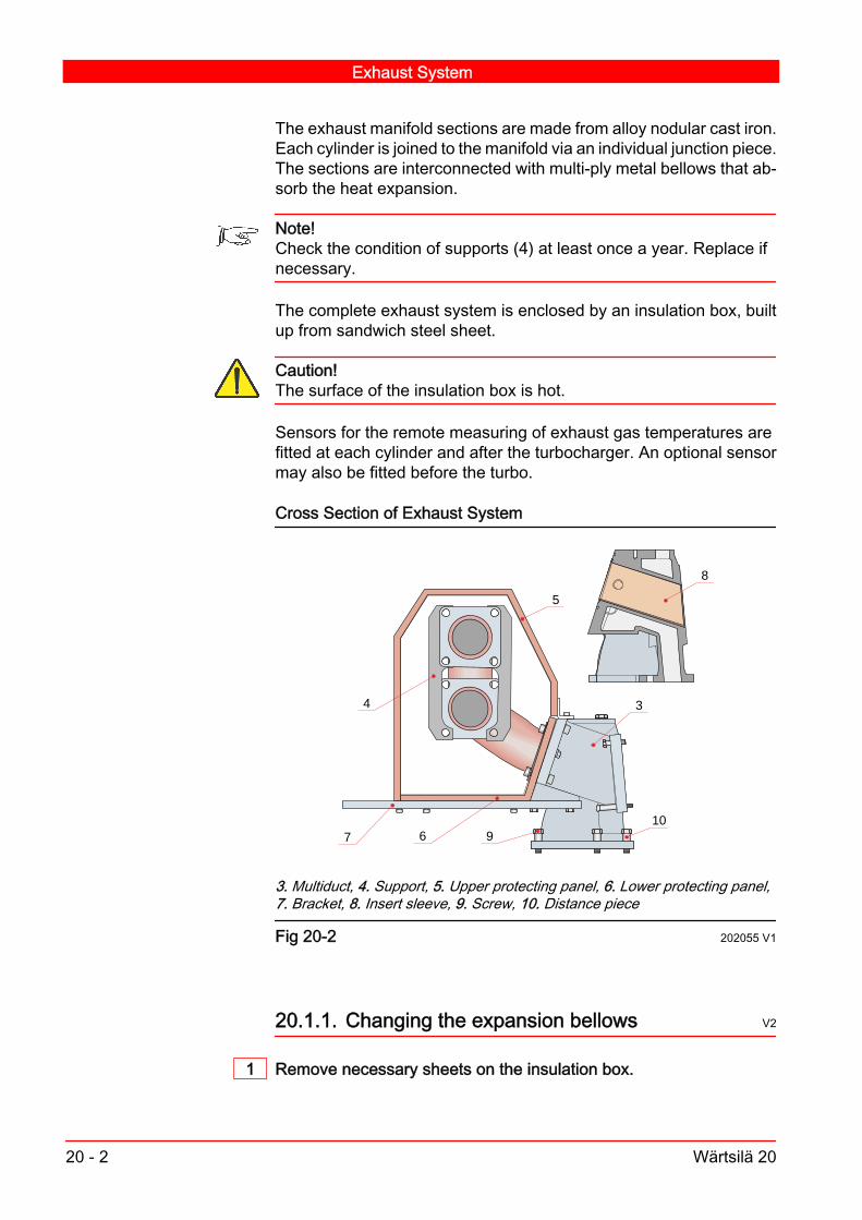
The exhaust manifold sections are made from alloy nodular cast iron.Each cylinder is joined to the manifold via an individual junction piece.The sections are interconnected with multi-ply metal bellows that ab‐sorb the heat expansion.
Note!Check the condition of supports (4) at least once a year. Replace ifnecessary.
The complete exhaust system is enclosed by an insulation box, builtup from sandwich steel sheet.
Caution!The surface of the insulation box is hot.
Sensors for the remote measuring of exhaust gas temperatures arefitted at each cylinder and after the turbocharger. An optional sensormay also be fitted before the turbo.
Cross Section of Exhaust System
8
5
3
1067
4
9
3. Multiduct, 4. Support, 5. Upper protecting panel, 6. Lower protecting panel,7. Bracket, 8. Insert sleeve, 9. Screw, 10. Distance piece
Fig 20-2 202055 V1
20.1.1. Changing the expansion bellows V2
1 Remove necessary sheets on the insulation box.
Exhaust System
20 - 2 Wärtsilä 20

2 Remove the screws and remove the expansion bellows.
3 Check that the exhaust pipe flanges are parallel. Position it on thesame centre line to avoid lateral forces on the bellows.
4 Mount the new expansion bellows and tighten the screws.
Note!The flow direction is marked with an arrow.
5 Examine the supports (4) for damage. Replace with new ones, if nec‐essary.
6 Mount necessary sheets and other parts.
Exhaust System
Wärtsilä 20 20 - 3

Exhaust System
20 - 4 Wärtsilä 20

21. Starting Air System V15
The engine is started with compressed air of max. 10 bar. Minimumpressure required is 7.5 bar with the engine at operating temperature.A pressure gauge (3) mounted on the instrument panel indicates thepressure after the pressure reducing valve (2). The air starter is controlled by solenoid valves (5,6) and start blockingvalve (7).As a precaution the engine cannot be started when the turning gearis engaged. Control air to the air starter is led through a blocking valve(7), mechanically blocked when the turning gear is engaged, thuspreventing start.
Starting Air System
Wärtsilä 20 21 - 1

Starting air system
STARTING AIR
301
3
2
5
4
7
1
6
1.Air starter,2.Pressure reducing valve,3.Gauge for starting air,4.Safety valve,5.Solenoid valve (5/2),6.Starter control valve,7.Start blocking valve301.Starting air inlet
Fig 21-1 202160 V2
21.1. Starting device, turbine air starter V16
The engine is provided with a turbine-type air starter. It is an air-op‐erated, two-stage-turbine-driven, and pre-engaged starter drive, de‐signed for operation with compressed air only. No lubrication is re‐quired in the supply air system.
Data and dimensionsType: Turbine driven airstarteracting on the flywheelWeight: 20 kgAir pressure: 8 bar
Starting Air System
21 - 2 Wärtsilä 20

The air starter can be grouped into: Integral relay valve Turbine Housing Gearbox Housing Bendix DriveWhen the engine has reached a speed of 115 RPM, the current is cutoff by a relay in the electronic speed measuring system, and the airstarter is automatically disengaged.In emergency situations (current failure or malfunctioning of controldevices), the air starter can be started with a manually-operatedvalve. This causes the automatic disengage control of the air starterto be out of operation. Hence, to avoid any overspeed of the air starter,the valve must be closed when the engines starts.
Warning!Do not operate the starter with compressed air unless it is properlyattached to the engine and engages the flywheel.
A valve prevents starting when the turning device is engaged (as wellas emergency starting by means of a valve).
21.1.1. Disassembly of starter V15
Mark each section of the starter for reference during assembly. Donot disassemble the starter any further than necessary to replace aworn or damaged part. Mark the turbine rotor and note its direction ofrotation.Have a complete set of O-rings, seals, screws and other hardwareavailable for assembly.
21.1.2. Cleaning and inspection of starter V15
1 Degrease all metal parts except bearings and the starter drive usingcommercially approved solvents.
2 Dry parts thoroughly.
Caution!Never wash bendix assembly or bearings in cleaning solvents. It isrecommended bearings be replaced with new parts.
3 Clean aluminium parts using a cleaning solution and soak for five mi‐nutes. Remove the parts, rinse in hot water and dry thoroughly.
Starting Air System
Wärtsilä 20 21 - 3

4 Clean corroded steel parts with commercially approved stripper.
5 Clean corroded aluminium parts using a cleaning solution. Immersethe parts in a chromic-nitric-phosphoric acid pickle solution. Rinsewith hot water and dry thoroughly.
6 Check for acceptable condition of parts.
7 Check all threaded parts for galled, crossed, stripped, or brokenthreads.
8 Check all parts for cracks, corrosion, distortion, scoring or generaldamage.
9 Check all bearing bores for wear and scoring. Bearing bores must befree of scoring lines.
10 Check the gear teeth and turbine housing ring gear for wear. Checkfor spalling, fretting, surface flaking, chipping, splitting, and corrosion.If wear is apparent, check the gear teeth dimensions.
21.1.3. Assembly of starter V16
Always press the inner race of ball bearings when installing onto ashaft. Always press the outer race of ball bearings when installing intoa housing. The rotor retention screw must be replaced each time theturbine rotor is removed. All parts should be degreased and aluminumparts cleaned. For overhaul, all parts are included in the overhaul kitshould be replaced.All screw threads are treated at the factory with a fastener retentioncompound. Every screw, 1/4 inch diameter or larger, must have adrop of Loctite 290 applied to the threads before being re-used,screws smaller than 1/4 inch diameter must have a drop of Loctite222 applied to the threads.
21.2. Starting air vessel and piping V2
An oil and water separator as well as a non-return valve should belocated in the feed pipe, between the compressor and the starting airvessel. At the lowest position of the piping there should be a drainvalve. Immediately before the starting air system, a non-return valveand a blow-off valve are mounted.Drain the starting air vessel from condensate through the drain valvebefore starting.
Starting Air System
21 - 4 Wärtsilä 20

The piping between the air vessels and the engines should be care‐fully cleaned when installing. Also later on they should be kept freefrom dirt, oil and condensate.The starting air vessels should be inspected and cleaned regularly. Ifpossible, they should then be coated with a suitable anti-corrosiveagent. Let them dry long enough.At the same time, inspect the valves of the starting air vessels. Toostrong tightening may result in damages on the seats, which in turncause leakage. Leaky and worn valves, including safety valves,should be reground. Test the safety valves with pressure.
21.3. Pneumatic system V15
The engine is equipped with a pneumatic system which controls thefollowing functions by means of a solenoid valves: Start of engine Stopping of engine Overspeed Protection Control of Air Waste GateThe staring system includes pressure reducing valve (2) and safetyvalve (4). Pressure reducing valve maintains the air pressure at cor‐rect level and safety valve ensures the pressure is at safe level for theair starter. The air starter is controlled by a solenoid valve (5) andblocking valve (7).
Starting Air System
Wärtsilä 20 21 - 5

Pneumatic system
113
12
8
11
10
102
4
1
6 5
7
9
9
1. Air starter 2. Pressure reducing valve 3. Gauge for starting air 4. Safetyvalve 5. Solenoid valve 6. Starter control valve 7. Start blocking valve8. Shut-off valve 9. Pneumatic stop cylinders 10. Main stop valve 11. Aircontainer 12. Solenoid valve
Fig 21-2 202161 V1
The system includes an air container (11) and a non-return solenoidvalve which ensures that the pressure in the system doesn't drop incase of low feed pressure. Fig 21-3 shows the solenoid valve. Thesolenoid valves can also be operated manually.The pneumatic overspeed trip devices (9), described in detail inChapter 22: Electro-pneumatic overspeed trip device, are controlledby a main stop valve (10). It is actuated by solenoid valve on an elec‐tric signal from the speed monitoring system, where by the enginestops.The solenoid valve is able to function as a local stop.
Note!When the engine is running, the air supply to the engine must alwaysbe open.
Starting Air System
21 - 6 Wärtsilä 20

21.4. Maintaining the pneumatic system V16
The system is built up from high quality components. It usually re‐quires no other maintenance than the draining of condensed waterfrom the vessel (11). The system function should however be checkedregularly.
Note!Regularly check the pressure after the pressure reducing valve (2).
Solenoid valve:In case of a fault in the electric function of the valve,test the mechanical function of the valve by pushing the button (1) ,see Fig 21-3. Should there be a mechanical malfunction, open thevalve and inspect the following:Check that the bores (2) and (3) and their seats are open and thegasket (4) is intact. Change the valve if it does not function aftercleaning.Water draining valve: Clean the valve if there is any disturbance. Thevalve can temporarily be disconnected by closing the main shut offvalve for overspeed system.Pressure reducing valve: The pressure reducing valve requires nomaintenance. If there is problem, change the valve.
Pneumatic components
A
1 4
2
3
B C
A:Airflow direction, B:Solenoid valve, C:Pressure reducing valve.1. Button 2. Bore 3. Bore 4. Gasket.
Fig 21-3 V1
Starting Air System
Wärtsilä 20 21 - 7

Starting Air System
21 - 8 Wärtsilä 20

22. Control Mechanism V3
During normal operation the engine speed is controlled by a governor(1) which regulates the injected fuel quantity to correspond with theload and engine speed.The regulation movement is transferred to the control shaft (10)through a adjustable link rod (2).The movement from the control shaft, to the injection pump fuel racks(16), is transferred through the regulating lever (6) and the spring (7).The torsion spring (5) enables the control shaft and, consequently,the other fuel racks to be moved to a stop position, even if one of theracks has jammed. In the same way the torsion spring (7) enables theregulating shaft to be moved towards fuel-on position, even if an in‐jection pump has jammed in a no-fuel position. This feature can be ofimportance in an emergency situation.The engine can be stopped by means of the stop lever (17). Whenthe stop lever is moved to stop position, the lever (18) actuates thelever (9) forcing the regulating shaft to stop position.The engine is provided with an electro-pneumatic device with trippingspeed about 15 % above the nominal speed. The electro-pneumaticdevice moves every fuel rack to a no-fuel position by means of apneumatic cylinder on every injection pump. The cylinder actuatesdirect on the fuel rack. The electro-pneumatic device can also be trip‐ped manually, see section 22.4.When starting, the governor will automatically limit the movement ofthe regulating shaft to a suitable value.The speed governor is provided with a stop solenoid by which theengine can be stopped remotely. The solenoid is also connected tothe electro-pneumatic overspeed protection system and to the auto‐matic stop system, which stops the engine at too low lubricating oilpressure, too high circulating water temperature, or at any other de‐sired function.
22.1. Maintaining the control mechanism V4
Warning!Pay attention to the functioning of the system. Any defect in the sys‐tem may result in over speeding of the engine and it may not be ableto take the load.
Control Mechanism
Wärtsilä 20 22 - 1

1 Clean and lubricate the racks, the bearings and the ball joints regu‐larly with lubricating oil. Ensure that the system works with minimalfriction.
2 Check the clearance of all connections. The total clearance may cor‐respond to 0.5 mm (maximum) of injection pump fuel rack positions.
3 Check the adjustment of the system regularly. For recommendationson adjustment of the system, see Chapter 4. For adjustment of stopposition, overspeed trip devices and starting fuel limiter, see Chapter22 : Checking and adjusting the fuel rack position.
4 Check that all the accessories are installed in the right position whenreassembling the system. Ensure that all nuts are tightened to theright torque. Ensure locking elements like pins, retainer rings andlocking plates are in the right position.
22.2. Check and adjustment
22.2.1. Checking and adjusting the fuel rack position V5
1 Checking the fuel rack position.a ) Set the governor lever in the maximum fuel position and the stop
lever in the stop position.b ) Check that the fuel rack position of all injection pumps is maxi‐
mum 3 mm.
Control Mechanism
22 - 2 Wärtsilä 20
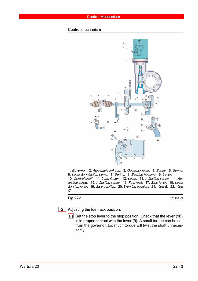
Control mechanism
3 04 0
A
A
A - A
C
B
2
31
4
15
5 6 7
8
911
12
12
2
16
10
17
18
19
20
2122
14
13
1. Governor. 2. Adjustable link rod. 3. Governor lever. 4. Screw. 5. Spring.6. Lever for injection pump. 7. Spring. 8. Bearing housing. 9. Lever.10. Control shaft. 11. Load limiter. 12. Lever. 13. Adjusting screw. 14. Ad‐justing screw. 15. Adjusting screw. 16. Fuel rack. 17. Stop lever. 18. Leverfor stop lever. 19. Stop position. 20. Working position. 21. View B. 22. ViewC.
Fig 22-1 202257 V3
2 Adjusting the fuel rack position.a ) Set the stop lever to the stop position. Check that the lever (18)
is in proper contact with the lever (9). A small torque can be setfrom the governor, too much torque will twist the shaft unneces‐sarily.
Control Mechanism
Wärtsilä 20 22 - 3
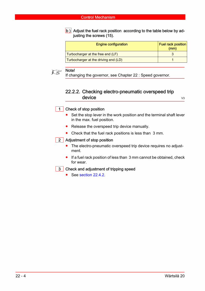
b ) Adjust the fuel rack position according to the table below by ad‐justing the screws (15).
Engine configuration Fuel rack position(mm)
Turbocharger at the free end (LF) 3Turbocharger at the driving end (LD) 1
Note!If changing the governor, see Chapter 22 : Speed governor.
22.2.2. Checking electro-pneumatic overspeed tripdevice V3
1 Check of stop position Set the stop lever in the work position and the terminal shaft lever
in the max. fuel position. Release the overspeed trip device manually. Check that the fuel rack positions is less than 3 mm.
2 Adjustment of stop position The electro-pneumatic overspeed trip device requires no adjust‐
ment. If a fuel rack position of less than 3 mm cannot be obtained, check
for wear.3 Check and adjustment of tripping speed
See section 22.4.2.
Control Mechanism
22 - 4 Wärtsilä 20

Electro-pneumatic overspeed trip device
3
21
4
1. Cylinder, 2.Piston, 3.O-ring , 4.Fuel rack
Fig 22-2 202251 V2
22.3. Speed governor V1
The engine can be equipped with various governor alternatives de‐pending on the kind of application. Concerning the governor itself, seethe attached governor instruction book.
22.3.1. Hydraulic governor drive V1
The governor is driven by a separate drive unit, which, in turn, is drivenby the camshaft through helical gears. The governor is fastened tothis drive unit and connected to the drive shaft through a serratedconnection. The serrated coupling sleeve is secured with spring pins.The governor, with drive, can thus be removed and mounted as a unitor the governor can be changed without removing the drive unit.Pressure oil is led, through drillings in the bracket, to the bearings andto a nozzle for lubricating the gears.
Data and dimensionsGovernor: Mechanical-hydraulic typeWeight: 19 kg
Control Mechanism
Wärtsilä 20 22 - 5

Check at recommended intervals: radial and axial clearances of bearings, gear clearance, oil drillings and nozzle to be open, serrated coupling sleeve to be firmly fastened to the shaft, serrations of coupling sleeve and governor drive shaft for wear.Change worn parts.
22.3.2. Removing the governor V4
1 Loosen the terminal shaft lever (3) and the governor electrical con‐nection.
2 Open the governor fastening screws (4). Pull the governor verticallyupwards. Ensure that the governor does not fall or rest on its drivingshaft, see Fig 22-1.
22.3.3. Mounting of governor V5
When mounting the governor, proceed as follows:1 Put the fuel rack and governor in a position according to Fig 22-4.
Governor terminal shaft position
100
2030
40
EUROPA 2231-1GWOODWARD 3161 WOODWARD UG-A
INCREASE F
UEL
0
10
1 11
1. Position indicator of governor.
Fig 22-3 202258 V2
2 The lever for governor must be assembled in a position according toFig 22-4.
3 Fit the link rod (2) between the levers and lock the adjustment.
4 Check according to section 22.2.1.
Control Mechanism
22 - 6 Wärtsilä 20

Governor shaft settings
A3
B
2
16
( 76 )
10
12
26 ±5 (Woodward)18 ±5 (Europa)
2. Adjustable link rod, 3. Lever for governor, 10. Control shaft, 12. LeverA: Governor shaft, B: Engine block
Fig 22-4 202259 V2
Table 22-2 Governor basic settings
Governor type Fuel rack (mm) Governor indicatorFD LD
3161 6 3 7.2UG-A 6 3 1.7Europa 2231-IG 6 3 2
22.4. Electro-pneumatic overspeed trip device V16
See Fig 22-4 Electro-pneumatic overspeed trip device.The overspeed trip device is controlled electronically . Air pressure ofmaximum 30 bar is used as an operating medium. The tripping speedis 15 % above the nominal speed.The three-way solenoid valve (10, Fig 21-2,) receives the stop signalfor overspeed from the electronic speed measuring system. Seechapter 21. section 21.3. The solenoid valve is also connected to thestop system.
Control Mechanism
Wärtsilä 20 22 - 7

When the solenoid valve opens, air is fed into the three-way valve thatconveys pressurized air to the cylinders (9, Fig 21-2.) Each injectionpump has one cylinder. The piston of the air cylinder actuates the pinon the fuel rack moving it to the stop position.The stop signal is normally energized for the time required to stop theengine completely. When de-energized, the air is evacuated throughthe three-way valve.The solenoid valve (10)Fig 21-2 can also be operated manually.
22.4.1. Check and adjustment of stop position V3
1 Check of stop position Set the stop lever in the work position and the terminal shaft lever
in the max. fuel position. Release the overspeed trip device manually. Check that the fuel rack positions are less than 3 mm.
2 Adjustment of stop position The electro-pneumatic overspeed trip device requires no adjust‐
ment. If a fuel rack position is more than 3 mm, check for wear.
22.4.2. Check of tripping speed V1
Check the tripping speed at idle by increasing the engine speed abovethe nominal speed by slowly bending the lever (12) with a suitablewrench in direction from the engine. When the nominal speed isreached and exceeded, the governor begins to decrease the fuel set‐ting, i.e. the control shaft must be bended against the governor force.
Warning!Do not increase the engine speed by more than 60 RPM above thetripping speed.
The tripping speed should be 15 % above the nominal speed, seechapter 06., section 06.1.
22.4.3. Adjustment of tripping speed V8
Adjustments will be made in the box of the electronic speed measur‐ing system, see instructions for speed measuring system, 23.
Control Mechanism
22 - 8 Wärtsilä 20

22.4.4. Maintenance V1
1 Three-way solenoid valve If the solenoid is out of order, replace it by a new one. If the valve does not move, clean all channels. Check the valve
piston. If air is leaking to the cylinders, change the sealings.
2 Air cylinder, Fig 22-2 . Check for wear. Check the tightness of the piston. Replace sealings by new ones,
if necessary. Take care not to deform the teflon ring outside theO-ring.
Lubricate the sealings and piston with lubricating oil. Check that the piston does not stick.
Control Mechanism
Wärtsilä 20 22 - 9

Control Mechanism
22 - 10 Wärtsilä 20
23. Instrumentation and Automation
23.1. UNIC automation system V9
The UNIC automation system is an embedded engine managementsystem. The system has a modular design. Some parts and functionsin the configuration are optional depending on application. The sys‐tem is specifically designed to handle the demanding environment ofmarine engines. Special attention has been paid to temperature andvibration endurance in this rugged design. This compact system canbe directly mounted on the engine as there are no dispersed externalcabinets or panels. The engine can therefore be delivered fully testedfrom factory. The number of inputs and outputs are determined tooptimally suit this application. The galvanic signal isolation is alsomade to match these needs.There are three different versions of the UNIC automation systemnamely: UNIC C1, C2 and C3. The type of automation system useddepends on the automation level.
UNIC C1 Automation SystemThis engine is equipped with UNIC C1 automation system.The system is a combination of the traditional approach of point-to-point wiring of sensor signals to an external alarm system, and amodern system handling fundamental engine safety and enginespeed control.Most sensors on UNIC C1 engines (see installation specific diagramsfor details) are connected directly to the external system for remotealarm & safety handling. Sensor signals used for local indication arealso wired to the LCP.
Instrumentation and Automation
Wärtsilä 20 23 - 1

Overview of UNIC C1 system
2
3
4
1
1. Local control panel 2. Engine safety module 3. Main control module4. Power distribution module.
Fig 23-1 V4
The UNIC automation system consists of the following major parts: Local Control Panel (LCP): Contains push buttons for local engine
control, as well as two graphical displays. Main Control Module (MCM): Handles all the start/stop
management and speed/load control functions of the engine. Thismodule is an optional for engines having mechanical governors.
Engine Safety Module (ESM): Handles fundamental enginesafety, and is the interface to the shutdown devices and some localinstruments.
Power Distribution Module (PDM): Handles fusing, powerdistribution, earth fault monitoring and EMC filtration in the system.It provides two fully redundant 24 VDC supplies to all modules,sensors and control devices. Common rail engines also have tworedundant 110 VDC supplies for the injector drivers.
Instrumentation and Automation
23 - 2 Wärtsilä 20

The system is handles the following major tasks and functions: Provides a local interface to the operator, including a local display
indicating all important engine measurements, an hour counterand a local control panel.
Interfaces & converts all sensors and control signals to theexternal systems.
Handles the fundamental engine safety (alarms, shutdowns,emergency stops, load reductions) including fully hardwiredshutdowns for engine overspeed (redundant), lube oil pressure,cooling water temperature and external shutdowns.
A high performance electronic speed/load controller with variousoperating modes (optional).
23.2. Mechanical design V10
The UNIC system is designed to meet very high targets on reliability.This includes special measures for redundancy, fault tolerance aswell as mechanical and electrical design.UNIC sensors and actuators are designed to be reliable, easy toservice and to calibrate. Flying lead design is introduced (whereverpossible) to avoid failure prone connectors.
Sensor with flying lead design
Fig 23-2 V1
Only screened dedicated Teflon insulated cables for the demandingengine environment are used on the engines. These well protectedpoint-to-point cables provide the most reliable solution, as they en‐sure good protection against electrical disturbances, high mechanicalstrength as well as good protection against chemicals and tempera‐ture.
Instrumentation and Automation
Wärtsilä 20 23 - 3

23.3. Parts of the UNIC System
23.3.1. Local control panel V17
The Local control panel (LCP) is a resilient electrical cabinet mountedon the front side of the engine. This panel is the local interface to startand stop the engine, and also to view engine measurements. TheLCP consists of the following switches and buttons: a mode selectorswitch, a start button, an emergency stop button and a reset button,along with WIP-1*, a graphical display screen, and WIP-2*, a bar-graph display screen.
Connecting box of UNIC C1
1 2
34
1. WIP-2* 2. WIP-1* 3. Emergency stop button 4. WCP-1*
Fig 23-3 V1
Instrumentation and Automation
23 - 4 Wärtsilä 20

23.3.1.1. WIP-1* and WIP-2* displays V4
WIP-1* & WIP-2* displays
Fig 23-4 V1
The WIP-1* display has indications of the followingmeasurements:- Engine speed, a graphical relative indication of 0...120% and
a numerical 4-digit indication.- Turbocharger speed A-bank, a numerical 3-digit indication.- Turbocharger speed B-bank, (if V-engine) a numerical 3-digit
indication.- Hour counter, a 5-digit numerical indication.
Bar graph indications for:- Lube oil pressure, 0...10 bar.- HT water temperature, 30...120 °C.
On WIP-1* there is a triangle symbol with a !-sign inside. The light forthis symbol indicates a failure either in the PDM, MCM, ESM orWIP-2*. Also a binary output Engine control system, minor alarm willactivate in this situation.
Instrumentation and Automation
Wärtsilä 20 23 - 5

Note!Some additional graphical symbols are appearing on WIP-1*, butthese are not used in UNIC-C1 application.
The WIP-2* display has bar graph indications of the followingmeasurements.- Fuel oil pressure, 0...16 bar- Starting air pressure, 0...16 bar- Control air pressure, 0...40 bar- Charge air pressure, 0...6 bar- HT water pressure, 0...6 bar- LT water pressure, 0...6 bar
Additionally there is a 4-digit numerical indication of the exhaust gastemperature (range 0...750 °C) for each bank (cylinder selectable withselector switch). This is utilised only in marine applications.On this display there is also pressure indications in PSI (in brackets)and the exhaust gas temperatures can either be displayed in °C or°F.Normal values are represented with green colour in the bar graphsleft of the measurement value, while abnormal values first turn yellow,then red. Abnormal values will create an alarm in the external alarmand monitoring system, as the same sensor signals as used inWIP-2*, in most cases are looped to the external alarm system.
Note!In case of a sensor failure or sensor signal wire break, the lowest LEDelement in the bar-graph will flash. In case the sensor or the wiringprovides an over-current, the highest LED element will flash.
23.3.1.2. Switches and buttons V15
Below a description of the switches and buttons used in the LCP.
Instrumentation and Automation
23 - 6 Wärtsilä 20

Control buttons and switches on the LCP
HS724 HS721 HS722 HS725 HS726
Fig 23-5 V3
Note!On power plant engines, this control panel only comprises an emer‐gency stop button.
HS724 Engine mode selector switchThis mode selector switch has the following four positions: Local: Local control of engine start and stop enabled. Remote: Remote control of engine start and stop enabled. Blocked: Starting is electrically blocked (both local- and remote
start). Blow: When the selector is in this position, it is possible to perform
a "blow" (an engine rotation check with indicator cocks open) whenpressing the local start button. The engine will not start (fuel shaftlimited to zero), only the starting air valve will be activated whilepressing the start button in this situation.
HS721 Start button By pressing this button, the engine will bestarted locally. A lamp in the button will turn on (green colour),when the engine is ready for start.
Note!In case the mode selector HS724 is in remote, blocked or blow posi‐tion, the local start signal is disabled.
HS722 Stop button By pressing this button, the engine will bestopped locally.
Note!In case the mode selector HS724 is in remote position, the local stopsignal is disabled. A re-start after a manually activated stop, will notrequire a reset.
Instrumentation and Automation
Wärtsilä 20 23 - 7

HS725 Shutdown reset button In case an automatic shutdown or
emergency stop has occurred, the shutdown circuit will latch.When the engine has stopped, a reset of this circuit can beperformed by pressing this button. When a reset is necessary,blue light will turn on in the button.
Note!Before a reset and a re-start is performed, the reason for the auto‐matic protective action must carefully be checked.
HS723 Emergency stop button (not visible in Fig 23-5) By pressingthis button, the engine will instantly shut down. The signal from thebutton goes directly to the Engine Safety Module (ESM) whichactivates the el. pneumatic stop solenoids, and also informs theMCM to enter shutdown mode i.e. to set the fuel shaft to zeroposition. The push button position is latching, and it needs to beturned to release. The emergency stop function in ESM & MCM isalso latching, and after the rotation speed has reached zero level,this latch can only be reset by pressing the reset button. Theemergency stop button is mounted separately from the otherbuttons and switches.
HS726 Exhaust gas temperature selector switch With this selectorswitch it can be selected, for which cylinder the exhaust gastemperature will be indicated on the display.
23.3.2. Main control module (MCM) V17
This module is an optional part of the system, in case of use of me‐chanical governorsThe MCM module is a versatile, configurable microprocessor basedcontrol- and data acquisition module. It has a variety of analogue anddigital measuring channels, as well as a number of analogue and bi‐nary outputs. The module is designed for mounting directly on theengine. Engine mounting allows the engine to be delivered fully testedfrom factory, and also allowing a faster commissioning.
Instrumentation and Automation
23 - 8 Wärtsilä 20

MCM module
Fig 23-6 V1
The CPU used in MCM is a high-performance Motorola PowerPCMPC561 controller. The module itself contains diagnostic features oninternal system integrity (like memory checksums, CPU watchdog,system temperature) as well as advanced I/O checks based on signalprocessing, like open/short circuit detection and sensor diagnostics.In addition, depending on application, also other application specificdiagnostics is available. The max. current consumption of MCM (alloutputs energised) is 2 A, while the idle comsumption is less than 200mA.There are four hardware controlled green LEDs in the MCM. In Table1 below the functions behind these LEDs are explained:Table 1.Usage of hardware controlled LEDs in MCM.
LED marking DescriptionPWR1 24V Indicates state of power supply 1 input.PWR2 24V Indicates state of power supply 2 input.SYS 24V Indicates state of power supply to module logics and microprocessor.SENS 24V Indicates state of power supply output used for module's I/O.
The MCM has one two-colour diagnostic LED (right-most in row,marked "DIAG"), which is used to indicate the execution state. Thefunction behind this LED is given in Table 2.Table 2: Usage of the software controlled two-colour LED in MCM.
Red Yellow Execution in DescriptionOFF OFF Undefined (boot
phase)No software is running.
ON OFF Bootloader 1 Bootloader 1 is running and waiting for connection.Flash OFF Bootloader 1 Bootloader 1 has established connection with tool.
Instrumentation and Automation
Wärtsilä 20 23 - 9

Red Yellow Execution in DescriptionOFF ON Bootloader 2 Bootloader 2 is running and is waiting for connection. Also in case of
software lock-up.Alt w/ yel‐low
Alt w/ red Bootloader 2 Bootloader 2 cannot find application; waiting for connection.
OFF Flash Bootloader 2 Bootloader 2 has established connection with tool. Application soft‐ware running.
The MCM module handles the following main tasks in the UNIC sys‐tem: Speed/load control Timing track control*
Note!* Only on engines with separate timing rack.
23.3.2.1. Speed controller V6
The main task of the MCM module is acting as the speed controllerfor the engine. The speed controller functionality is fully embedded inthe module, and optimised to suit Wärtsilä power plant engines aswell as ship genset- and main engine applications. On engines equip‐ped with the UNIC system, the module supports various sub-modes,needed for various types of applications, see section 23.4.1.1.To meet high robustness demands (e.g. in case of to signal failuresor other disturbance), the UNIC system will always be capable to op‐erate in droop mode, if premises for other modes are not met. In orderto meet high demands in terms of reliability, two speed sensors aresimultaneously used by the controller. If one speed sensor fails, theoperation will be uninterrupted.Speed controller parameters are verified and if necessary changedat the test run facilities at the engine maker, i.e. parameters do nor‐mally not have to be changed at the installation. However, in casesome changes are necessary, a separate service tool needs to beconnected to the module. Downloaded settings are permanently stor‐ed in the module's flash memory, and are not lost at a power failure.See section 23.4.1.1, for detailed information about the speed con‐troller functionality.
23.3.2.2. In/out signals V3
The UNIC-C1 system has a number of binary input- and output sig‐nals used for control and information purposes. Safety-critical inputsignals must externally be furnished with 22 kΩ termination (end-)resistors for wire break detection. See the wiring diagram for wiringdetails. All binary output signals from the MCM are connected via in‐
Instrumentation and Automation
23 - 10 Wärtsilä 20

ternal opto-couplers, for galvanic isolation and protection of the en‐gine-built electronic module. Binary outputs from switches/buttonsand the ESM module are connected directly.
23.3.2.3. Binary Inputs V3
The UNIC-C1 system is equipped with the following binary input sig‐nals: OS7302 Remote startIf no start blocking is active that is the generating set is in stand-bymode and output "IS872 Engine ready for start" is active, the activa‐tion of this input (closed contact) initiates a start of the generating set.The input is activated for minimum 0.5 seconds, after this the startprocess continues by itself. The input is disabled when the HS724blow/blocked/local/remote switch is in blow, blocked and local posi‐tion. OS7304 Remote stopActivation of this input (closed contact) initiates an immediate stop ofthe generating set. When the generating set has reached zero speed(+ a short delay), the system automatically enters stand-by mode and"IS872 Engine ready for start" output is set high. The engine can nowbe restarted without performing a reset. The input is disabled whenthe HS724 blow/blocked/local/remote switch on the engine is in blow-,blocked- and local position. As shutdown mode has higher prioritythan start mode, simultaneous activation of start and stop (remotelyor locally) results in a stop. OS7305 External shutdown 4 (emergency stop)Activation of this input (closed contact) initiates an instant shutdownof the generating set. This shutdown is a latching function, and re‐quires a reset. The input is in parallel with the local emergency stopbutton. The external contact must be equipped with a 22 kΩ resistorfor wire break monitoring. An emergency stop is not overridden byany position of the HS724 blow/blocked/local/remote switch. Asemergency stop mode has the highest priority, activation of any othercommand simultaneously is overruled, if this input is activated. OS7309 External shutdown 1 (from switchboard)Activation of this input (closed contact) initiates an instant shutdownof the generating set. This shutdown is a latching function, and re‐quires a reset. OS7312 External start blocking 1A start is prevented, if this input is activated (open contact). OS163 Speed increase
Instrumentation and Automation
Wärtsilä 20 23 - 11

Activation of this input (closed contact) ramps up the speed referenceof the internal speed controller. During parallel running in droop mode,the activation of this input leads to a gradual increase of the gener‐ating set load. The same input is also used during synchronization. OS164 Speed decreaseActivation of this input (closed contact) ramps down the speed refer‐ence of the internal speed controller. During parallel running in droopmode, the activation of this input leads to a gradual decrease of thegenerating set load. The same input is also used during synchroni‐zation.
23.3.2.4. Binary Outputs V7
The UNIC-C1 system is equipped with the following binary outputsignals: IS181 Speed switch 1 ("engine running")This speed switch is a signal, from the ESM module and activates(contact closes) at 40% of rated speed. It represents the "engine run‐ning" level, and gives this information to systems and devices externalto the generating set. Contact rating: 110 VDC / 0.5 A. IS1741/IS1742 Overspeed shutdown status IS2011 Lube oil pressure shutdown statusThis alarm signal informs that the generating set has shut down dueto low engine lube oil pressure. The signal derives input from a switchin the ESM module. The contact is open in case of Lube oil pressureshutdown. Contact rating: 60 VDC / 0.3 A. CV223 Pre-lubrication pump controlThis control signal is a potential free,optically coupled, output signalwhich is active (closed contact) in the stop and stand-by mode. Aftera delay (same delay as alarm-blocking), it de-activates at start-upwhen the rotational speed reaches the run mode level (300 rpm). ALED on the opto-coupler indicates that the contact is closed. Contactrating: 30 VDC / 2 A or 250 VDC / 0.4 A. HS724 Local/remote indicationThis status signal indicates whether the mode switch HS724 local/remote/blocked/ blow on the local control panel is in remote positionor local/blocked/blow position. The changeover contact is configuredin such a way, that the local position contact is closed for local, andthe remote position contact is closed for remote. It is not possible toremote start and stop the generating set, if the switch is in local,blocked or blow position. A shutdown is however always possiblethrough the OS7305 External shutdown 4 (emergency stop) input. IS7602 Stop/shutdown 1 status
Instrumentation and Automation
23 - 12 Wärtsilä 20

This status signal is a potential free opto-couple output signal usedto inform that a stop, shutdown or emergency stop is active, and thatthe generating set has shut down. The contact opens if there is a stop/shutdown. A LED on the opto-coupler indicates when the contact isclosed. The signal is used to let external systems & devices know ifthe generating set is running or not. Contact rating: 30 VDC / 2A. IS4011 HT temperature shutdown statusThis alarm signal indicates that the generating set has shut down dueto high engine HT water temperature. The signal derives input froma switch in the ESM module. The contact is open in case of HT watertemperature shutdown. Contact rating: 60 VDC / 0.3 A. OS441 Pre-heater controlThis control signal is a potential free,optically coupled, output signalwhich is active (closed contact) in the stop and stand-by mode. Aftera delay (same delay as alarm-blocking), it de-activates at start-upwhen the rotational speed reaches the run mode level (300 rpm). ALED on the opto-coupler indicates that the contact is closed. Contactrating: 30 VDC / 2 A or 250 VDC / 0.4 A. IS780 Alarm blockingThis blocking signal is active (closed contact) in stop and stand-bymode. It de-activates at generating set start when the rotational speedreaches run mode level (300 rpm) after a delay. Contact rating: 24VDC / 0.2 A. IS7305 External shutdown 4 status (emergency stop status)This status signal informs that the generating set has been shut downby the safety system on activation of the remote or local emergencystop button. Contact open if there is an external shutdown. Contactrating: 60 VDC / 0.3 A. IB7324 Shutdown statusThis status signal informs that the generating set has been automat‐ically shut down by the safety system. Contact open if there is a shut‐down. The signal is used by external systems in ships. Contact rating:60 VDC / 0.3 A. IS872 Engine ready for startThis status signal is a potential free opto-couple output signal usedto inform that the generating set is ready for start, that is, it is in stand-by mode. The contact is closed if the engine is ready, and no startblockings is active. A LED on the opto-coupler indicates when thecontact is closed. Contact rating: 30 VDC / 2 A. IS875 Start failure NS881 Engine control system, minor alarm NS886 Engine control system, major failure
Instrumentation and Automation
Wärtsilä 20 23 - 13

This alarm signal informs that there is a major problem (causing agenerating set shutdown). The signal derives input from the MCMmodule. It activates only in case of a system related failure.The reasons for a major failure are: MCM module failure. Dual power supply failure to the MCM or to the actuator driver. Actuator major failure. Dual speed sensor failure.Contact open in case of major failure. Contact rating: 24 VDC / 0.2 A.
23.3.3. Engine instrumentation V1
The following standard set of sensors and solenoids for monitoring,alarm and safety are mounted on the engine. The location of the sen‐sors and the solenoids are shown below.
Table 23-3 Standard sensors
Standard sensors CodeFuel oil pressure, engine inlet PT101Lube oil pressure, engine inlet PT201Lube oil pressure, engine inlet PTZ201Starting air pressure, engine inlet PT301Control air pressure, engine inlet PT311HT Water pressure, jacket inlet PT401LT Water pressure, CAC inlet PT471Lube oil pressure, TC inlet (mainengines only)
PT271
Charge air pressure, engine inlet PT601Charge air pressure, engine inlet PT601-2Fuel oil temperature, engine inlet TE101Lube oil temperature, engine inlet TE201Lube oil temperature, TC outlet (mainengines only)
TE272
HT Water temperature, jacket inlet TE401HT Water temperature, engine outlet TE402HT Water temperature, engine outlet TEZ402LT Water temperature, CAC inlet TE471LT water temperature, LOC outlet TE482Exhaust gas temperature, after eachcylinder
TE5011A..
Instrumentation and Automation
23 - 14 Wärtsilä 20

Standard sensors CodeExhaust gas temperature, TC inlet TE511Exhaust gas temperature, TC outlet TE517Charge air temperature, engine inlet TE601Fuel rack position GT165Engine speed 1 ST173Engine speed 2 ST174Engine speed, primary ST196PEngine speed, secondary ST196STubocharger speed SE518Fuel oil injection pipe leakage LS103-ALube oil low level in oil sump LS204Lube oil filter pressure difference PDT243Stop lever in stop position GS171Turning gear position GS792
Table 23-4 Control solenoids
Control solenoids CodeStart fuel limiter (If forward actingRE2231)
CV151
Governor stop solenoid (If RE2231) CV152Stop solenoid 1 CV153-1Stop solenoid 2 CV153-2VIC control solenoid CV381Starting solenoid CV321Charge air limiter, valve 1 CV657-1Charge air limiter, valve 2 CV657-2
Table 23-5 Optional sensors
Optional sensors CodeLube oil temperature, engine outlet TE202Lube oil temperature, LOC outlet TE232LT water temperature, CAC outlet TE472Air temperature, TC inlet TE600Charge air temperature, CAC inlet TE621Crankcase pressure PT700Fuel oil filter pressure differentialswitch
PDS113
Fuel oil standby pump switch PS110
Instrumentation and Automation
Wärtsilä 20 23 - 15

Optional sensors CodeLube oil press switch, standby pump PS210HT water press switch, standby pump PS410LT water press switch, standby pump PS460
Sensors location for UNIC C1 (TC at free end), operating side
ST196S
ST174# PDS113
TE101
TE401#3 PSZ401
CV161
GS166 #3CV153-1CV153-2
PT700 #2GT165GS171
1234
TE5011A... *
ST173
ST196P
PT101PS110 #4PT401PS410 #4
GS792CV321PT301
TE 700#....*
#2 TE600
#2 TE621
SE518
LS103A
TE402TEZ402
#) Optional, #2) FAKS/CBM-option, #3) If main engine, #4) Stand by pump op‐tions, *) Depending on cylinder configuration.
Fig 23-7 V1
Instrumentation and Automation
23 - 16 Wärtsilä 20

Sensors location for UNIC C1 (TC at free end), rear side and drivingend
TE272 #3
#2 TE232
PT601-2TE601PT601 TE511TE517
TE482
#2 TE202
LS204PS460 #4 PT271 #3
PT471TE471#2 TE472
PDT243
PT201
PTZ201PS210 #4
TE201
PT311
#2) FAKS/CBM-option, #3) If main engine, #4) Stand by pump options,*) De‐pending on cylinder configuration.
Fig 23-8 V1
Instrumentation and Automation
Wärtsilä 20 23 - 17

Sensors location for UNIC C1 (TC at driving end), operating side
ST196PST196S
ST173ST174
PT271#3
TE621#2
GS171
GS166
TE401
TE101
#4 PS410
# PDS113
TE402,TEZ402
#3
TE5011A...*GT165
#5CV381
#2PT700 #2TE600
CV161
GS792CV321
PT301
TE700#...*
SE518
LS103A
CV153-2
CV153-1
#) Optional, #2) FAKS/CBM-option, #3) If main engine, #4) Stand by pump op‐tions,*) Depending on cylinder configuration,#5)If VIC (Variable inlet valve).
Fig 23-9 V1
Instrumentation and Automation
23 - 18 Wärtsilä 20

Sensors location for UNIC C1 (TC at driving end), rear side anddriving end
TE601 #6 CV657TE511
TE517
#3 TE272
#2 TE202
TE201
#2 TE472
LS204
PT471#4 PS460
PT601-2PT601TE471
TE482
PSZ401 #3
PS110 #4
PT401
PT311
PT101PDT243
#4 PS210
PT201
PTZ201
#2) FAKS/CBM-option, #3) If main engine, #4) Stand by pump options,*) De‐pending on cylinder configuration,#6)If AWG (Air waste gate).
Fig 23-10 V1
Even if the above mentioned sensors are considered as standard theamount and type of sensors can in special cases vary, depending onthe needs for various installations. The actual set of sensors and otherelectrical equipment mounted on the engine, as well as alarm, loadreduction and shutdown set points, can be found in the installationspecific documentation. See, Chapter 09: Specific Installation data.
23.3.4. Engine Safety Module ESM V3
The ESM (Engine Safety Module) module handles the fundamentalengine safety, but also a number of speed measuring functions andit feeds these signals to dedicated instruments. The ESM is also theinterface to the engine shutdown devices and local instruments andthe module constitutes also the major signal interface to external sys‐tems of the engine.
Instrumentation and Automation
Wärtsilä 20 23 - 19
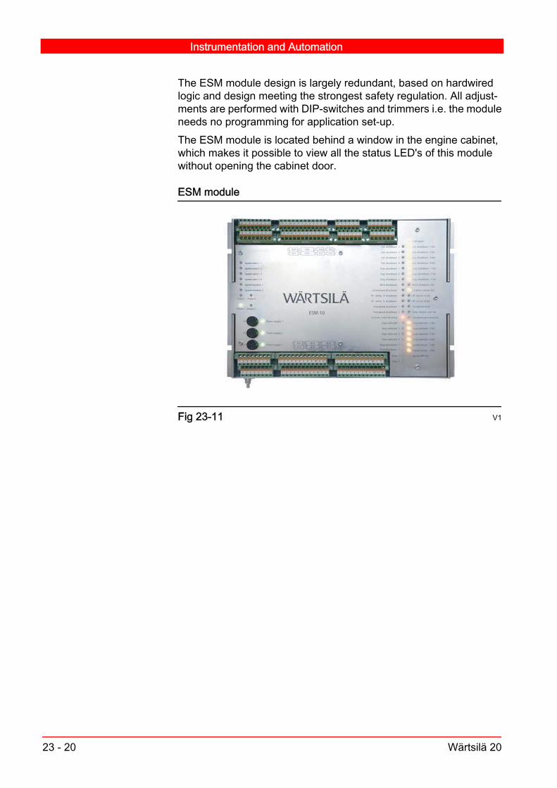
The ESM module design is largely redundant, based on hardwiredlogic and design meeting the strongest safety regulation. All adjust‐ments are performed with DIP-switches and trimmers i.e. the moduleneeds no programming for application set-up.The ESM module is located behind a window in the engine cabinet,which makes it possible to view all the status LED's of this modulewithout opening the cabinet door.
ESM module
Fig 23-11 V1
Instrumentation and Automation
23 - 20 Wärtsilä 20

Front panel of ESM
Fig 23-12 V1
1.Fuses for power supply.2.LED indications for function of module.3.Connectors (inputs/outputs).
Instrumentation and Automation
Wärtsilä 20 23 - 21

23.3.4.1. ESM power supply V2
ESM internal power supply principle
Primarypowersupply,X11:1 -3
Secondarypowersupply,X12:1 -3
24 V+5 V-5 V
+3,3 V
24 V+5 V-5 V
+3,3 V
24 V+5 V-5 V
+3,3 V
24 V+5 V-5 V
+3,3 V
Supply 1failure
Supply 2failure
Supply 3 or 4failure
Power supply 1for main logic
Power supply 2for stop circuit 2
Power supply 3for isolated engine
speed output
Power supply 4for isolated TCspeed outputs
Failuredetection
Failuredetection
Failuredetection
24 V+5 V-5 V
+24 V
24 V+5 V-5 V
+24 V
24 V+5 V-5 V
+24 V
24 V+5 V-5 V
+24 V
Failuredetection
Main supplyfailure
Failuredetection
Backup supplyfailure
F1
F2
F3
Fig 23-13 V3
Instrumentation and Automation
23 - 22 Wärtsilä 20

To ensure that the module is functional in all situations, full redun‐dancy is achieved by combining the double incoming power suppliesto the module. Supply failure detection:
- Failure on any supply activates ESM alarm output.- Supply failures are detected on:
Primary, (Power supply 1). Secondary, (Power supply 2). Power supply 1-4, (internal power supplies).
LED indications (green) provided:- Power 1, (primary).- Power 2, (secondary).- Fuses 1-3, (internal supplies).
Fuse values for ESM:- F1 = 3,15 AT- F2 = 3,15 AT- F3 = 0,25 AT
Instrumentation and Automation
Wärtsilä 20 23 - 23

23.3.4.2. Speed measuring and speed switches V18
Speed measuring and overspeed protection principle
Enginespeed
sensor 1,X13 :1-3
f / U
Sensor 1failure
detection
Enginespeed
sensor 2,X14 :1-3
f / U
Sensor 2failure
detection
Overspeedtrip circuit 1,
115%Overspeed 1
Compare &fail detection
Max select
Overspeedtrip circuit 2,
115%Overspeed 2
Engine speedoutput 1,X27 :7-8
U / IEngine speed
output 2,X28 :7-8
Internal speedsignal
Power supply 2
Engine speedpulse,
X27 :1-2f // f
Overspeed 1SD status,
X25 :5-6
Overspeed 2SHD status,
X25 :7-8
Speed diff.failure
Speed sensor2 failure
Speed sensor1 failure
Power supply 3
U // I or U
Fig 23-14 V1
The engine speed is measured with two independent speed sensors(see section 23.3.4.3) with separate supply circuits and with separatesensor failure detection circuits. The sensors are of inductive prox‐imity PNP-type. The frequency from the speed sensors are convertedinto analogue voltages proportional to the rotational speed. The volt‐age signals are used to trig the internal overspeed trip circuits in ESM.Both overspeed limits are fixed to 115 % of rated engine speed.
Failure detection: Frequencies of the two speed measuring channels are compared
to each other. A speed differential failure is triggered when thedifference between the speed signals is greater than 5 %. Speeddifferential failure indication is disabled if rotational speed < speed
Instrumentation and Automation
23 - 24 Wärtsilä 20

switch 1. The higher speed value (if different) is used as an internalspeed signal for controlling the analogue outputs and the speedswitches.
Short circuit detection. Wire break detection. Sensor failure and speed differential failure trigs ESM alarm output
after 2 s delay, if failure remains.Speed outputs: Engine speed output 1 (0-10 VDC or 4-20 mA depending of ESM
type) is connected to external systems. The signal is galvanicallyisolated and short circuit proof.
Engine speed output 2 ( 4-20 mA) is used internally for localindication (in WIP-1*).
Overspeed shutdown: Trigging point for overspeed shutdown 1 is 115 % of rated engine
speed. Trigging point for overspeed shutdown 2 is also 115 % of rated
engine speed. Driver outputs Stop solenoid 1 and Stop solenoid 2 activate the
two stop solenoids CV153-1 and CV153-2. Stop solenoid 2 is onlyactivated in case of emergency stop/overspeed.
LED indications provided: Speed sensor 1 failure, yellow. Speed sensor 2 failure, yellow. Speed differential failure, yellow. Speed pulse 1, green. Speed pulse 2, green. Speed switch 1 ("engine running"), green. Overspeed shutdown 1, red. Overspeed shutdown 2, red.Status/control outputs provided: Speed switch 1 is used as "engine running" information, and is
part of the external interface of the engine. The same internalswitch also controls the hour counter.
Speed switch 2 has configurable switching level and is also partof the external interface of the engine.
The two overspeed status switches IS1741 and IS1742 areconnected in series external to ESM, and are part of the binaryoutput signals of the engine.
Instrumentation and Automation
Wärtsilä 20 23 - 25

23.3.4.3. ESM speed sensor V4
The rotational speed of the generating set is measured with a touchfree inductive PNP-type proximity sensor. A 24 V DC current is sup‐plied to the sensor from the ESM. The third pin of the sensor givesthe speed proportional pulse train output. The pulse output voltagelevel varies between two fixed levels: 0 V DC and 24 V DC.The electronics of the M12x1 flying lead sensor is resin-moulded intoa tubular housing of nickel plated brass.
a ) Mounting the sensor: Turn the engine until the top of a cog is visiblein the sensor mounting hole. Carefully screw in the sensor by hand.Unscrew it approximately 1.5 revolutions for a sensing gap of 2.0±0.5mm, and tighten the counter nut well with a spanner.
Note!Do not run the engine while the sensor is being adjusted.
Engine speed sensor
2.0 ± 0.5 mm
24VDC
12
3
1. Black 2. Brown 3. Blue.
Fig 23-15 V2
23.3.4.4. Stop and shutdown signals V20
Lubricating oil pressureA dedicated safety sensor (PTZ201 lubricating oil pressure) is con‐nected to the ESM to activate the shutdown if the lubricating oil pres‐sure is low. This analogue sensor (separate from the one connectedto external systems) shuts down the engine at predefined pressureand delay set-points in the ESM.Set-points for low lubricating oil pressure shutdown: 2.0 bar 2 seconds (delay)If a sensor failure is detected, the shutdown is blocked and the sensorfailure is indicated.
Instrumentation and Automation
23 - 26 Wärtsilä 20

Provided sensor failure detection: Sensor failure indicated when the signal is out of range (<3.5 mA
or >20.5 mA). ESM alarm output activates after 2 seconds, if the failure remains.Provided LED indications: Lubricating oil pressure sensor failure, yellow. Lubricating oil pressure shutdown, red. Lubricating oil pressure start blocking, redProvided status outputs: LO oil pressure shutdown status is part of the external signal
interface of the engine. Oil pressure start-block is part of the external signal interface of
the engine.
HT water temperatureDedicated safety sensors (TEZ402 HT water temperature, jacket out‐let) are connected to the ESM to activate the shutdown, if the HT watertemperature is too high. The PT-100 signals of these analogue sen‐sors are converted into internal voltage signals at the input stages inthe ESM, and are used for further processing. A 4-20 mA output de‐rived from the higher of these signals is used for local indication of theHT water temperature on the WIP-1*.Set-point for high HT water temperature shutdown: 110 °C
Note!In main engines in ship installations, this shutdown is disabled, andload reduction is initiated on the basis of another sensor signal in theexternal system of the engine.
Provided sensor failure detection: Sensor failure indicated when the signal is out of range. ESM alarm output activates after 2 seconds, if the failure remains. If a sensor failure is detected, the shutdown is blocked and the
sensor failure is indicated.Provided LED indications: HT water temperature sensor failure, yellow. HT water temperature shutdown, red.Provided status output: HT temperature shutdown status is part of the external signal
interface of the engine.
Instrumentation and Automation
Wärtsilä 20 23 - 27

23.3.4.5. Shutdown reset V7
There is a Shutdown reset input on ESM, and this is connected inparallel with the reset input of MCM (if used). Reset has to be pressedafter all automatic shutdowns, as all shutdowns are latching in UNICsystem. A reset will release this latch, and a start of the engine ispossible to perform. Reset does however not override shutdown sig‐nals that are still active. The ESM reset input is disabled when rota‐tional speed is more than 2 % of rated speed.LED indication provided: Shutdown reset, yellow.
23.3.4.6. Other ESM inputs/outputs V17
The following additional inputs are used in the ESM: Stop 1 is activated by the MCM (if used) or by the local and remote
stop signals. Activation of this input keeps the primary electro-pneumatic stop solenoid and the governor stop solenoidenergized, and the engine shuts down. This input is latching, thatis, activated until a predefined delay has elapsed, or until the resetis pressed. A red LED indicates that the Stop 1 input is activated.In this situation, an external status signal, the binary output Stopstatus is activated.
Stop 2 is activated by the LCP during an engine blow situation.Activation of this input keeps the primary electro-pneumatic stopsolenoid and the governor stop solenoid energized during the blowprocedure, to secure that the engine does not start. This input isnon-latching , that is, reset is not necessary after the blow. A redLED indicates that the Stop 2 input is activated. In this situation,an external status signal, the binary output Shutdown status is notactivated.
Main controller shutdown is activated by the MCM (if used) in caseof an automatically generated shutdown. Activation of this inputkeeps the primary electro-pneumatic stop solenoid and thegovernor stop solenoid energized, and the engine shuts down.This input is latching, that is, reset is required to release theshutdown. Signal interruption failure detection (using a 22 kΩresistor) is provided between the two modules. LED indicators forMain controller shutdown (red) and Main controller shutdownfailure (yellow) are provided.
External shutdown 2 is connected to the external safety system.Activation of this input keeps the primary electro-pneumatic stopsolenoid energized, and the engine shuts down. This input islatching, that is, reset is required to release the shutdown. A signalinterruption failure detection (using a 22 kΩ resistor in marine
Instrumentation and Automation
23 - 28 Wärtsilä 20

configurations) is provided between the two modules. LEDindicators for External shutdown 2 (red) and External shutdown 2failure (yellow) are provided.
External shutdown 4 is connected to an external emergency stopsignal, and the signal is in parallel with the local HS723 Emergencystop button. Activation of this input keeps both electro-pneumaticstop solenoid and the governor stop solenoid energized, and theengine will shut down. This input is latching, that is, reset isrequired to release the shutdown. Signal interruption failuredetection (using a 22 kΩ resistor in marine configurations) isprovided between the module and the external emergency stopbutton. LED indicators for External shutdown 4 (red) and Externalshutdown 4 failure (yellow) are provided.
The following additional outputs are used in the ESM:
Stop status activates when the manual stop is activated. Shutdown status activates in case any ESM initiated shutdown or
the External shutdown 4 input is activated. Stop/shutdown status 1 activates when the manual stop has been
activated, or in case any ESM-initiated shutdown or an externalshutdown input is activated.
External shutdown status 2 activates in case the Externalshutdown 2 input is activated.
External shutdown status 4 output in the ESM activates in casethe External shutdown 4 (emergency stop) input is activated.
23.3.5. Power distribution module (PDM) V20
The power supply of the engine is set up according to overviewscheme below.
Instrumentation and Automation
Wärtsilä 20 23 - 29

Power supply and distribution principle
External system(Ship or power plant)
Off-engineequipment
Engine mounted equipment
MainsupplyBackupsupply
External system- Main power supply- Backup power supply
Off-engine equipment- DC/DC converter - AC/DC converter- Galvanic isolation
PDM- EMC filter- Overvoltage protection- Transient suppressors- Over-current protection (fuses)- Power failure detection- Earth fault detection
Engine
Fig 23-16 442381 V1
The PDM's (Power Distribution Module's) purpose is used to distrib‐ute the power supply to all electronic equipment on the engine. Themodule handles filtering of the power supplies, protection againstover-voltage and voltage transients and monitoring of earth faults.The whole power supply system is floating in respect to ground (PE)(providing that the both external supplies are isolated). PDM is sup‐plied with two supplies which are redundant. Only the supply to thefuel rack speed actuator's driver is by-passing the PDM, all otherconsumers are connected through this module.The following features are provided in PDM: Monitoring of voltages Short circuit protection EMC filter Over-voltage protection Transient suppressors Power failure detection Earth fault detection Reverse polarity protection
Instrumentation and Automation
23 - 30 Wärtsilä 20

PDM module
Fig 23-17 V1
Internally, the PDM is designed in the following principal way.
Principal internal design of PDM
EFD*
EFD* BUS
BUS
AUX #1 & #2
PSS #124 VDC
PSS #224 VDC
= voltagemonitoringpoint
EFD*
EFD* BUS #1
BUS #2
AUX #1 & #2
PSS #124 VDC
PSS #224 VDC
= voltage monitoring point
*) when EFD not handled by external supply
Fig 23-18 V1
Instrumentation and Automation
Wärtsilä 20 23 - 31

LED indications are provided for the input supply voltages, for thefuses and for earth fault monitoring. Input voltages are monitored and if the supply voltage drops below
18VDC, the PDM alarm output is activated. The LED indicationcorresponding to the input with the low voltage is then turned off.
Each fuse has an individual (green) LED. The LED will turn off ifthe fuse has blown.
An earth fault is indicated with LED indications, positive line failureand negative line failure separately. The earth fault detectionalarm level is adjustable between 3 kΩ - 300 kΩ with a 10-steprotational switch. The earth fault detection can also be turned offwith this switch. A time delay for the activation of the earth fault isselectable between 0 - 128 seconds with a 9-step rotationalswitch.
Fuse sizes are: BUS 1: 10A BUS 2: 10A AUX 1: 10A AUX 2: 10AThe PDM has the following failure outputs: 1 x potential free output for general failure 1 x potential free output for earth faultThe failure outputs are open when active, meaning that total powerfailure also will result in an alarm.
23.4. Functionality of the UNIC
23.4.1. Speed controller
23.4.1.1. Speed controller V17
In the speed control algorithm the speed reference is compared withthe measured engine speed. The difference between these signalsconstitutes the input to a PID-controller. The regulation output of theMCM controller will accordingly change, to sustain the reference level.
Instrumentation and Automation
23 - 32 Wärtsilä 20

This output will set the position request of the fuel actuator, i.e. controlthe diesel fuel rack position. The fuel actuator can either be an electro-hydraulic actuator or a full-electric actuator
23.4.1.2. Dynamics V2
The PID-controller uses different sets of dynamic parameters for op‐eration under acceleration, under no-load conditions and under load‐ing conditions, to obtain optimal stability at all times. The PID settingsare speed dependent for start acceleration and for open circuit break‐er/clutch conditions, and load/speed dependent when the engine isloaded. A special speed deviation dependent feature is also provided,to minimise large speed fluctuations. The proportional gain is speeddeviation mapped, for more aggressive control in case of large devi‐ations from the reference speed.
23.4.1.3. Limiters V3
The three available limiters are the following: A start fuel limiter is active during the engine start, up to a rotational
speed level of 20 rpm below the rated speed. The start fuel limitersettings in this 8-point table are speed-dependent, and the limiterworks in combination with a speed reference ramp used at enginestart. The acceleration ramp is set for an optimal acceleration rate.
A charge air pressure limiter (8-point map) can be used to reduceover-fuelling and black smoke at load steps at low engine loadlevels. At low load levels, this feature also improves the loadacceptance of the engine.
A load-dependent fuel limiter can be used to set an envelope ofmaximum fuelling at various engine loads. This feature improvesthe load acceptance of the engine, but it is also used as a limiterfor the maximum load output.
23.4.2. Synchronizing/clutch-in V1
23.4.2.1. Genset V1
When the engine is started, it initially operates in CB open controlmode. The speed accelerates up to idle speed, and thereafter (whenOS176 Idle select input is low) ramps up to rated speed. When theengine speed reaches rated speed, an external device (synchronizer)activates the synchronization. Commands from this synchroniser unitactivate the two binary inputs OS163 Speed increase and OS164Speed decrease to obtain the requested speed level. The speed ref‐erence can be altered between a pre-determined min. and max.
Instrumentation and Automation
Wärtsilä 20 23 - 33

speed reference level by using these inputs, thus the internal speedreference is in this way biased so that the generator frequency exactlywill match the plant frequency.When the two frequencies are totally matched (in addition also thephase matching and the generator voltage level must match), thegenerator breaker can be closed. Alternatively an analogue syn‐chronizer can be used (connected to the dedicated input OS160 An‐alogue synchronizer). This input is used for synchronization, if binaryinput OS160 analogue synchronizer enable is set true.
Step mode is active when INC/DEC pulse mode selector is set true
INC pulses
DEC pulses
Time
Engine speed reference
Eng
ine
spee
d re
fere
nce
Pulse step size
Fig 23-19 V1
Instrumentation and Automation
23 - 34 Wärtsilä 20

Ramping mode is active when INC/DEC pulse mode selector is setfalse
INC pulses
DEC pulses
Time
Engine speed reference
Eng
ine
spee
d re
fere
nce
Ramp rate
Fig 23-20 V1
There are two ways to affect the speed reference with these binaryinputs. If ramp mode is configured true (default), the speed referencewill be ramped as long as one of these inputs is high. If step mode isconfigured true, the speed reference is affected a pre-determinedstep each time one of these input signals is set high (flank trigged).
23.4.2.2. Main Engines V2
Main engines on ship installations are using an analogue speed ref‐erence signal instead of the above described OS163 Speed increaseand OS164 Speed decrease inputs. When input OS7325 Analoguespeed ref. select is activated, the MCM speed controller will use thereference signal OT190 Analogue speed reference. The internalspeed reference will be ramped up and down according to the levelof this signal. Max. and min. speed are predefined (configurable).
Instrumentation and Automation
Wärtsilä 20 23 - 35

If input OS7326 Fixed speed select is activated, the speed will (re‐gardless of other input signals) be ramped up or down to a pre-de‐termined fixed speed level. Further synchronisation/clutch-in can thenbe performed from this level by using inputs OS163 Speed increaseand OS164 Speed decrease.
Clutching the first engine
Time
Idle Speed
Clutch in speed
+Clutchin speedwindow-Clutchin speed window
Eng
ine
spee
d re
fere
nce
Fig 23-21 V1
Clutching the second engine
Fig 23-22 V2
Instrumentation and Automation
23 - 36 Wärtsilä 20

Speed goal reference during start sequence, depending on pre-set ofbinary inputs.
Time
OS7601 Clutch-in requested OS7321 Fixed speed ref select OS7325 Analogue speed ref selectOS176 Idle speed
Depending of status:
Star
t ram
ping
Fixed speed
Clutch in speed
Analogue speed
Rated speed
Idle speedIdle speed
Eng
ine
spee
d
Fig 23-23 V1
23.4.3. Engine loading, general V2
When the generator breaker or clutch is closed, the engine is oper‐ated in droop mode, kWmode or isochronous load sharing mode, pri‐marily depending of the pre-selection of the OS7328 kW control en‐able and OS7329 Isochronous load sharing enable inputs. The kWand isochronous load sharing modes require that the system to vitalparts is functional, if important signals are missing or not communi‐cated, the functionality will automatically switch over to droop mode.
23.4.4. kW control mode V20
In kW control mode, the control loop is a true load control loop wherethe engine speed is only used for safety purposes. An internal loadreference is compared to the measured engine load (UT793 Gener‐ator load input signal). The error is the input to a PID controller for theload control loop.The output of the controller determines the position of the fuel rack,and thus the output is set to sustain the load reference levelkW control mode is used particularly on power plant engines. Thiscontrol mode is activated when the input OS7328 kW control ena‐ble is activated and the GS798 Generator breaker status and GS799Grid breaker status inputs are both closed. The kW control mode hasmost benefits in base load applications where the grid frequency sta‐
Instrumentation and Automation
Wärtsilä 20 23 - 37

bility is low. The engine load does not fluctuate according to the fre‐quency in the same way as if it would do in speed control mode withdroop.
kW control mode
0 100 %50
1
2
3
4
6
5
1. Engine speed (rpm) 2. Engine load (%) 3. Operating area for true kW control4. Operating point with old load reference 5. Operating point after ramping tonew load reference 6. Grid frequency
Fig 23-24 V2
If the grid frequency is not within a predefined speed window, or if theUT793 Generator load signal fails, the control mode automaticallytrips to droop mode. The speed reference is updated continuously bythe speed control loop in kW control, which means that if a trip occurs,the transfer is almost bumpless. By toggling the OS7328 kW controlenable input, kW mode is restored, providing that all enabling condi‐tions are met.When entering this mode from CB open control mode, the load ref‐erence is initially set to a predefined base level. This is done to avoidrisk of reverse power of the genset when entering this mode from theCB open control mode. The internal load reference is then ramped upto the externally given reference OT795 kW reference with a prede‐fined ramp rate.
Instrumentation and Automation
23 - 38 Wärtsilä 20

Relative base load reference
3
1
1
2
2
4
5
6
11
8
7
9
10
1. Engine load reference 2. Time 3. Gen CB is closed 4. Engine loadreference 5. Engine load reference is started to ramp to goal reference6. Relative base load is set to engine load reference 7. OS7321, Engine unload8. Gen CB open command is set active 9. Engine load reference 10. Engineload 11. Relative trip load
Fig 23-25 V4
When input OS7321 Engine unload is activated, the load referencetarget is set to a base load level, and the load reference is rampeddown according to a predefined unload ramp rate. When reaching thislevel, the OS7602 Gen. breaker open command output goes high(engine disconnected) and CB open control sub-mode is entered.
Instrumentation and Automation
Wärtsilä 20 23 - 39

In kW control mode, the controller uses dedicated load-dependentPID settings.
23.4.5. Droop mode V8
When two or more engines are operating in parallel, some kind of loadsharing must be provided. Load sharing means that each engine willcontribute equally to the total power demand, and it ensures that loadchanges are absorbed evenly by the engines in operation.Droop control is a basic load sharing method, by which parallel run‐ning engines share the load by decreasing their internal speed refer‐ence proportionally to an increase in load. No communication or sig‐nalling is needed between the engines in this mode. The droop valueis normally set to 4 %, but the setting can if necessary be changed.Too low droop value means that the load can potentially start oscil‐lating between the engines. Too high droop value means that theplant's frequency decreases more steeply with the load level.
Droop mode
1. Operating PointBefore load change2. Operating point after load change3. Operating point after correction
Nominal net frequency
Droop curve
Engine load
100[%]
500
Ref. correction
Speed reference [rpm]
Fig 23-26 V1
Load sharing based on droop, means that the power managementsystem (PMS) may after major load changes have to compensate theeffect derived from the droop slope. Therefore, this system shouldunder such conditions activate the OS163 Speed increase or theOS164 Speed decrease input of UNIC system (in so called cascadecontrol) to compensate for the droop slope i.e. to ensure that the busfrequency is kept within a certain window regardless of net load level.The PMS system must however have a control dead-band imple‐mented, allowing for an uneven load or frequency drift of 1... 2 %.
Instrumentation and Automation
23 - 40 Wärtsilä 20

External system compensates the negative effect derived from Droop slope
PID
SPEED CONTROL
REFERENCESPEED
ACTUALSPEED
SPEED PICK-UP
ERROR
ACTUATOR
ACTUATORDRIVER
-
+ PID
SPEED CONTROL
REFERENCESPEED
ACTUALSPEED
SPEED PICK-UP
ERROR
ACTUATOR
ACTUATORDRIVER
-
+
Plant net Load
Plant net frequency
Frequency is biased by increase/decrease pulses (influences the controller’s speed reference)
PLC/PMS
Fig 23-27 V1
In droop mode the load of the engine is ramped up by setting theOS163 Speed increase input high. The internal speed reference inUNIC increases with a pre-defined rate (the rate of change is config‐urable), and this determines thereby the loading rate. Increase com‐mands are used until the load level of this engine is equal to othersets running in parallel. In other words, the OS163 Speed increaseand OS164 Speed decrease inputs shall not only be used for busfrequency compensation, but also for biasing the load between theengines.
Instrumentation and Automation
Wärtsilä 20 23 - 41

Ramp control in droop mode
INC pulses INC pulsesDEC pulses DEC pulses
Pulse step sizeEngine speed reference
Engine speed reference
Eng
ine
spee
d re
fere
nce
Eng
ine
spee
d re
fere
nce
Time Time
Fig 23-28 V1
When it is intended to shut an engine down, the engine load can inthe corresponding way be decreased, by activating the OS164 Speeddecrease input. When the load has reached a low level, the generatorbreaker can be opened, and the engine be shut down.Droop mode can also be used on larger grids, but this is not recom‐mended (particularly if the grid frequency has high variations) due tothe risk of engine overload. Droop mode is also a backup mode to kWcontrol mode and isochronous load sharing mode, if conditions tokeep the engines in these modes of some reason are not fulfilled.
23.4.6. Isochronous load sharing mode (optional) V3
An engine operating in isochronous load sharing mode, will keep thespeed at the speed reference, regardless of the load level of the sys‐tem. Engines operating in isochronous mode need to have the samerelative speed reference for load sharing.In generator engines, the speed reference is initially always ratedspeed. In propulsion engines the speed reference is set according tothe analogue speed reference from the propulsion system controller.
Instrumentation and Automation
23 - 42 Wärtsilä 20

Operating point diagram
Speed reference[rpm]
Engine load[%]0 10050
Operating pointbefore load change
Operating pointafter load change
Nominal net frequence& speed reference
Fig 23-29 V1
Two or more main engines running in parallel (analogue speed ref.selected is true on at least one engine) will monitor the speed refer‐ence of the engines which have analogue speed reference selectedtrue (over the LS-CAN load sharing bus), and (if several) select thehighest one for all engines. The speed reference can only be adjustedbetween the end levels lowest analogue set speed ref. and highestanalogue set speed ref. If fixed speed is selected on one of the en‐gines running in parallel, all the other engines are switched to followthe speed reference of this engine. Now the speed of the system canbe increased/decreased using the OS163 Speed increase andOS164 Speed decrease inputs or OT160 Analogue synchronizer onthe engine switched to fixed speed. If one engine has the OS7326Fixed speed select input set high, this engine will be master for theother engines running in this mode.A pre-defined ramp rate is used, to ramp to fixed speed (if the OS7326Fixed speed select input us used) before the OS163/OS164 inputswill affect the speed reference. The speed reference can only be ad‐justed between a pre-defined min. and max. level.Load sharing in isochronous load sharing mode is provided with com‐munication over LS-CAN. Each engine monitors the relative load itselfand of the other engines connected to the same electrical compart‐ment, and calculates a relative system load. The unit compares itsown relative load with the relative system load, and biases its internalspeed reference, until the two loads are equal.Always when a new engine is connected to the load sharing com‐partment it should be softly uploaded. In order to provide soft upload‐ing of an engine in isochronous load sharing mode a pre-defined ramprate is used. The value of the engine specific load sharing ramp is
Instrumentation and Automation
Wärtsilä 20 23 - 43

zero during normal isochronous load sharing operation, i.e. when therelative load of the engines on the load sharing bus is equal. Unload‐ing of an engine running in isochronous load sharing mode is ach‐ieved by setting the input OS7321 Engine unloading high. When theinput is activated the unloading is performed by ramping down theengine load similarly to the uploading case. When the relative engineload reaches a pre-defined trip level, the binary output OS7602 Gen‐erator breaker open cmd, and OS7603 De-clutch will go high, and theengine will thereby be disconnected.
Ramping of LS ramp during uploading
ramping of LS ramp during uploading of engine in isochronousload sharing mode
OS7327, emergencyloading rate
engine added toisochronous group
LS ra
mp
OS7321, engineunload
time
0
plant load
Load sharing gain
upload ramprate
emergency upload
ramprate
the LS ramp affects directly theload sharing error, in order to
achieve soft uploading
global speedreference
load sharingerror
local speedreference
Fig 23-30 V1
Instrumentation and Automation
23 - 44 Wärtsilä 20

Ramping of LS ramp during unloading
ramping of LS ramp during unloading of engine in isochronousload sharing mode
LS ra
mp
OS7321, engineunload
OS7327, emergencyloading rate
time
plant load - trip load
Load sharing gain
unload ramprate
emer
genc
y unlo
ad
ram
prat
e the LS ramp affects directly theload sharing error, in order to
achieve soft unloading
0
global speedreference
load sharingerror
local speedreference
Fig 23-31 V1
Load sharing bias is provided, if it is desired to run some of the en‐gines on the same electrical compartment on a constantly differentrelative load compared to the other engines. This is achieved by usingthe IT796 Asymmetric load sharing bias input.In isochronous load sharing mode, the controller will use dedicatedload & speed depended PID settings.
23.4.7. Backup governor (optional) V2
In some mechanical main propulsion engine applications a mechan‐ical backup governor is provided. Should the MCM speed controllerhave a dual power supply loss or otherwise fail, the mechanical back‐up governor will automatically take over. This mechanical governorwill however only provide fundamental speed governing in droop,while special dynamic features and control modes will not be provi‐ded.
Instrumentation and Automation
Wärtsilä 20 23 - 45

Instrumentation and Automation
23 - 46 Wärtsilä 20