document transmittal form - nuclear regulatory …document transmittal form to : nrc attn:doc....
TRANSCRIPT
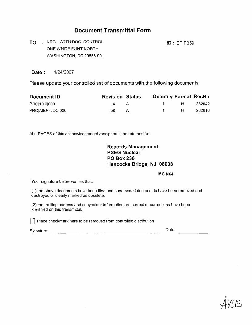
Document Transmittal Form
TO : NRC ATTN:DOC. CONTROL ID: EPIP059ONE WHITE FLINT NORTH
WASHINGTON, DC 20555-001
Date 1/24/2007
Please update your controlled set of documents with the following documents:
Document IDPRCI10.01000
PRClAIEP-TOCl000
Revision Status
14 A
58 A
Quantity Format RecNo11
H 282642
H 282616
ALL PAGES of this acknowledgement receipt must be returned to:
Records ManagementPSEG NuclearPO Box 236Hancocks Bridge, NJ 08038
MC N64
Your signature below verifies that:
(1) the above documents have been filed and superseded documents have been removed anddestroyed or clearly marked as obsolete.
(2) the mailing address and copyholder information are correct or corrections have beenidentified on this transmittal.
[D Place checkmark here to be removed from controlled distribution
Signature: Date:
4¼1S
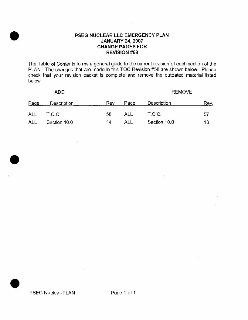
PSEG NUCLEAR LLC EMERGENCY PLANJANUARY 24, 2007
CHANGE PAGES FORREVISION #58
The Table of Contents forms a general guide to the current revision of each section of thePLAN. The changes that are made in this TOC Revision #58 are shown below. Pleasecheck that your revision packet is complete and remove the outdated material listedbelow.
ADD REMOVE
Page Description Rev. Page Description Rev.
ALL T.O.C. 58 ALL T.O.C. 57
ALL Section 10.0 14 ALL Section 10.0 13
PSEG Nuclear-PLAN Page 1 of 1

PSEG NU(EMERGEI
TABLE OF CONTENI
January
REVIS
Sec Title
1.0 INTRODUCTION
2.0 ASSIGNMENT OF RESPONSIBILITY
3.0 EMERGENCY ORGANIZATION
4.0 EMERGENCY RESPONSE SUPPORTAND RESOURCES
5.0 EMERGENCY CLASSIFICATION SYSTEM
6.0 NOTIFICATION METHODS -RESPONSE ORGANIZATION
7.0 EMERGENCY COMMUNICATIONS
8.0 PUBLIC INFORMATION
9.0 EMERGENCY FACILITIES AND EQUIPMENT
10.0 ACCIDENT ASSESSMENT
11.0 PROTECTIVE RESPONSE
12.0 RADIOLOGICAL EXPOSURE CONTROL
13.0 MEDICAL SUPPORT
14.0 RECOVERY AND REENTRY PLANNING
15.0 EXERCISES AND DRILLS
16.0 RADIOLOGICAL EMERGENCYRESPONSE TRAINING
17.0 EMERGENCY PLAN ADMINISTRATION
3LEAR LLCNCY PLAN'S/SIGNATURE PAGE
24, 2007
ION 58
Rev. Pages
12 13
16 14
22 50
12 5
12
13
12
10
17
14
14
13
11
9
12
18
15
2
23
9
3
15
16
5
7
2
3
6
10
Date
08/30/2006
08/30/2006
08/30/2006
08/30/2006
08/30/2006
08/30/2006
08/30/2006
08/30/2006
08/30/2006
01/24/2007
08/30/2006
08/30/2006
08/30/2006
08/30/2006
11/03/2004
08/30/2006
5 08/30/2006
AIEP - TOC 1 OF 9 Rev. 58
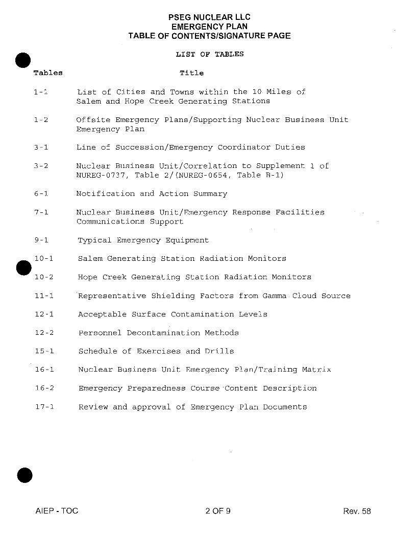
PSEG NUCLEAR LLCEMERGENCY PLAN
TABLE OF CONTENTS/SIGNATURE PAGE
LIST OF TABLES
Tables Title
1-1 List of Cities and Towns within the 10 Miles ofSalem and Hope Creek Generating Stations
1-2 Offsite Emergency Plans/Supporting Nuclear Business UnitEmergency Plan
3-1 Line of Succession/Emergency Coordinator Duties
3-2 Nuclear Business Unit/Correlation to Supplement 1 ofNUREG-0737, Table 2/(NUREG-0654, Table B-1)
6-1 Notification and Action Summary
7-1 Nuclear Business Unit/Emergency Response FacilitiesCommunications Support
9-1 Typical Emergency Equipment
10-1 Salem Generating Station Radiation Monitors
10-2 Hope Creek Generating Station Radiation Monitors
11-1 Representative Shielding Factors from Gamma. Cloud Source
12-1 Acceptable Surface Contamination Levels
12-2 Personnel Decontamination Methods
15-1 Schedule of Exercises and Drills
16-1 Nuclear Business Unit Emergency Plan/Training Matrix
16-2 Emergency Preparedness Course Content Description
17-1 Review and approval of Emergency Plan Documents
AIEP - TOC 2 OF 9 Rev. 58

PSEG NUCLEAR LLCEMERGENCY PLAN
TABLE OF CONTENTS/SIGNATURE PAGE
LIST OF FIGURES
Figures
1-1
2-1
2-2
2-3
2-4
2-5
2-6
2-7
2-8
2-9
2-10
2-11
3-1
3-2
3-3
Title
10 and 50 Mile Radii from Salem and Hope Creek GeneratingStations
PSE&G Corporate Organization
PSEG Nuclear Organization
Delaware State Interface
New Jersey State Interface
Decision Chain Protective Actions/ For Events Classified asGeneral Emergency
State of Delaware/Radiological Emergency Response/ StateOrganization
State of New Jersey/Radiological Emergency Response/StateOrganization
Salem County/County Emergency Organization
Cumberland County/County Emergency Organization
New Castle County (NCC)/County Emergency Organization
Kent County/County Emergency Organization
Nuclear Business Unit/Station Response with ExternalInterface
Nuclear Business Unit/Station Response with External Interface
Nuclear Business Unit/Emergency Operations Facility/EmergencyResponse Organization with External Interface
AIEP - TOC 3OF9 Rev. 58
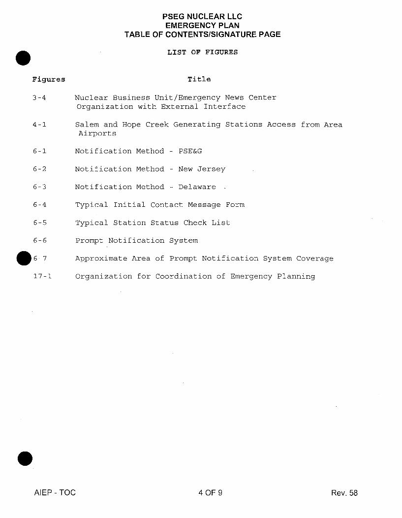
PSEG NUCLEAR LLCEMERGENCY PLAN
TABLE OF CONTENTS/SIGNATURE PAGE
LIST OF FIGURES
Figures
3-4
4-1
6-1
6-2
6-3
6-4
6-5
6-6
.6-717-1
Title
Nuclear Business Unit/Emergency News CenterOrganization with External Interface
Salem and Hope Creek Generating Stations Access from AreaAirports
Notification Method - PSE&G
Notification Method - New Jersey
Notification Method - Delaware -
Typical Initial Contact Message Form
Typical Station Status Check List
Prompt Notification System
Approximate Area of Prompt Notification System Coverage
Organization for Coordination of Emergency Planning
AIEP - TOC 4 OF 9 Rev. 58
PSEG NUCLEAR LLCEMERGENCY PLAN
TABLE OF CONTENTS/SIGNATURE PAGE
LIST OF NUREG-0654 CROSS REFERENCE TO PLAN
NUREG-0654REF.SECTIONPart Al.al.b1.c
l.d
I.e
2.a2.b34
EMERGENCYPLANSECTION
Section 2 & 4Section 2Section 2 Figures
NUREG-0654REF.SECTIONPart E1
234 .a-n
56
7
Part Fl.al.b
1.c
EMERGENCYPLANSECTION
Section 6
Section 3Section 3,4N/AN/AAtt 2Section 3
Part B1
2
3
45
7.a
7.b
7.c
7.d
8
9
Part Cl.a1.b1.c2.a2.b34
SectiorSectiorSectiorSectiorSectiorSectiorSectiorSectiorSectiorSectiorSectiorAtt 2
SectionSectionSectionSectionSectionSectionSection
SectionSectionN/AN/A
33333333334
i.e
l.f
2
3
SectionSectionSectionN/ASection
Section
SectionSection
Section
Section
Section
Section
Section
Section
Section
Section
Section
Section
SectionSectionSection
666
6
6
77
7
Part G
1.a-d
2
3.a
3 .b
4.a
4.b4.c5
Part H12345.a-d
6.0
7.0
13
15
8
8
3&9
9
3&8
888
3&444 Att 44444 Att2
Section 9Section 9
Section 3&9Section 10
Part D1234
5.0, Att 55.0, Att 5
AIEP - TOC 5 OF 9 Rev. 58
PSEG NUCLEAR LLCEMERGENCY PLAN
TABLE OF CONTENTS/SIGNATURE PAGE
LIST OF NUREG-0654 CROSS REFERENCE TO PLAN
NUREG-0654REF.SECTIONPart H78910Ii12
Part I123.a3.b456789
1011
Part Jl.aI.bl.cl.d23456.a6.b6.c789
10 .a10 .b10.c10 .d-1
EMERGENCYPLANSECTION
(contd)Section 9Section 1Section 9Section 9Section 9Section 9
0
Att 5SectionSectionSectionSectionSectionSectionSectionSectionSectionSectionN/A
SectionSectionSectionSectionSectionSectionSectionSectionSectionSectionSectionSectionAtt 11N/AAtt 11Att 11SectionN/A
10101010101010,101010
9
NUREG-0654REF.SECTIONPart J10.m1112
Part K1.a-g23.a3.b45.a5.b6.a-c7Part L1234
Part M1234
Part N10al.b22 .a-e
3 .a-f
45
Part 01l.al.b2
SectionSectionSectionSectionSectionSectionSectionSectionSection
SectionSectionSectionSection
SectionSectionSectionSection
SectionSectionSectionSectionSectionSectionSection
EMERGENCYPLANSECTION
(contd)Section IN/AN/A
I
121212121212121212
13131310
14141410
15151515151515
111111111I111111
3, 95, Att 5
Section 16Section 16N/ASection 16
AIEP - TOC 6 OF 9 Rev. 58
PSEG NUCLEAR LLCEMERGENCY PLAN
TABLE OF CONTENTS/SIGNATURE PAGE
LIST OF NUREG-0654 CROSS REFERENCE TO PLAN
NUREG-0654REF.SECTION
Part 034.a4.g4.h5
Part P12345678910
EMERGENCYPLANSECTION
NUREG-0654REF.SECTION
EMERGENCYPLANSECTION
(contd)Section 16Section 16Section 16Section 16Section 16
Section 16Section 17Section 17Section 17Section 17Section 1TOC, Att 1TOC, List ofSection 17Section 17
NUREG Cross Ref.
AIEP - TOC 7 OF 9 Rev. 58

PSEG NUCLEAR LLCEMERGENCY PLAN
TABLE OF CONTENTS/SIGNATURE PAGE
SUMMARY OF REVISIONS
This revision is an editorial change as all changes were approved under the indicated Design ChangePackage (DCP) number.
* R46E was removed from Table 10-1 under Salem Generating Station Radiation Monitors UnitOne. This monitor was deleted under DCP #80057520. A 50.54q was performed and is a recordin SAP under Order #80057520 Operation #0085. (AD P0001)
* R36 was removed from Table 10-1 under Salem Generating Station Radiation Monitors UnitTwo. This monitor was deleted under DCP #80057146. A 50.54q was performed and is a recordin SAP under Order #80057146, Operation #0030, Sub-Operation #0470. (AD P0014)
* R46E was removed from Table 10-1 under Salem Generating Station Radiation Monitors UnitTwo. This monitor was deleted under DCP #80057587. A 50.54q was performed and is a recordin SAP under Order #80057587 Operation #0085. (AD P0001)
* 9RX513 and 9RX514 were abandoned in place years ago. These monitors are being removedfrom Table 10-2 as under DCP #80058722/4EC3634 they have been removed from the RM- 11display. An EP evaluation of the New RM-11 system was conducted under Order #80058722Operation #0080.
* 9RX596, 9RX 597, 9RX 600, 9RX 601, 9RX 604 and 9RX 605 were removed under DCP#80042523. These monitors are being removed on Table 10-2. A 50.54q was performed and is arecord in SAP under Order #80042523 Operation #0460. (AD P0021 and P005 1)
AIEP - TOC 8 OF 9 Rev. 58
PSEG NUCLEAR LLCEMERGENCY PLAN
TABLE OF CONTENTS/SIGNATURE PAGE
SIGNATURE PAGE
Prepared By: Gary Young 01-18-2007Date
Sections Revised: NONE(List Non-Editorial Only Sections) Date
Reviewed By N/A10CFR50.54q Effectiveness Reviewers Date
Reviewed By N/
Reviewed By: -
Reviewed By: N/
ADepartment Manager
anager
Date
Date
DateA
Nuclear Oversight Director(If Applicable)
PORC Review and Station Approvals
N/AMtg. No. Salem Chairman
N/ADate
N/ASalem Plant Manager
N/AMtg. No. Hope Creek Chairman
N/ADate
N/AHope Creek Plant Manager
N/ADate
N/ADate
Effective date of this revision: 01/24/2007Date0
AIEP - TOC 9 OF 9 Rev. 58
SECTION 10ACCIDENT ASSESSMENT
1.0 General
1.1 Emergency Action Level Determination
The plant parameter and instrument values used to identify an emergency class areprovided in Plan Attachment 5-1 and 5-2.
2.0 Accident Assessment and Instrumentation - Salem Generating Station
There are several monitoring systems used to support emergency planning activitiesat Salem Generating Station. The primary systems utilized are listed below.- Radiation Monitoring System (See Radiation Monitoring System Manuals)
and CBD DE-CB. RM - 0064(Q)- Safety Parameters Display System (SPDS)- Reactor Coolant Sampling System
2.1 Radiological Monitoring Instrumentation - Salem Generating Station
The radiological monitors consist of process radiation monitors, effluent radiationmonitors and area radiation monitors, (see Table 10-1). The system continuouslydisplays and/or records the radiation levels in key areas. The Unit 1 RadiationMonitoring System (RMS) is a predominately analog system while the Unit 2Radiation Monitoring System (RMS) is predominately a digital system. Bothsystems have been modified to comply with the recommendations of NUREG 0578.The Unit 2 RMS consists of individual sensors with independent micro processors(MPs), which are able to perform a variety of tasks. The MPs can convert count ratepulses from the individual channels into various engineering units or factor in flowrate information to provide information to the operator to aid accident assessment.The information is fed to two mini computers, which are in a master-slaveconfiguration for redundancy. The operator, by keying in certain commands, is ableto display selected radiation monitoring channels in a particular elevation on hisdisplay screen. The information may be trended for pre-selected time periods, asrequired. The listing of the radiation monitoring channels, which may be used toassess an accident, is provided in Table 10-1.
Permanent monitor channels are not always available at a location of interest andthe use of portable area monitors may be required during an accident. Unit 2 RMSuses a "communication loop" in which the radiation monitors in the "field"communicate to the computer via a loop of wire.
PSEG NUCLEAR LLC - EP 10.1 Rev..14

2.2 Process and Area Monitors
In order to provide the operators with essential information on plant conditionsduring an emergency, various plant processes are continuously monitored. Many ofthese processes involve Limiting Conditions for Operations (LCO) and are controlledby the Technical Specifications. If an LCO parameter "goes out of specification" itrequires the operators to implement the action required by the associated actionstatement. The intent of this action is to take corrective measures under abnormalconditions before a situation becomes more serious. These parameters would bemonitored closely during an accident for assessment purposes. These processindications that are monitored are also listed in Table 10-1.
2.3 Gaseous Release Path Monitoring
In addition to the main plant vent, a monitored vent, the other potential majorrelease points from the plant during an accident are the main steam dump valves,pilot operated relief valves and the turbine driven auxiliary feed water pump.Procedures have been developed to monitor these potential release pathways andperform the necessary dose assessment.
2.4 Reactor Coolant and Containment Air Sampling - Salem Generating Station
Reactor coolant and containment gaseous activity sampling (normal and highactivity/emergency samples) will be performed using station procedures and thenormal day-to-day sampling systems. The plant vent, which is the final releasepoint, is continuously monitored by the RMS for noble gases. The iodine cartridgecan be physically removed and taken into a laboratory for analysis by a multi-channel analyzer available in the station (Hope Creek will provide backup analysis).There are also provisions provided in the plant vent for extracting a grab sample.
Analysis of reactor coolant and containment air samples provides detailedinformation on the status of the reactor core. These samples can be used toprovide confirmation of a loss of the fission product barriers.
3.0 Accident Assessment Instrumentation - Hope Creek Generating Station
There are several monitoring systems used to support emergency planning activitiesfor the Hope Creek Generating Station.
The plant computer systems and their functions are described in Final SafetyAnalysis Report (UFSAR). Specifically, the primary systems utilized to supportemergency planning activities are:
Control Room Integrated Display Systems (CRIDS)(UFSAR Section7.5.1.3.3.1)
PSEG NUCLEAR LLC - EP 10.2 Rev. 14

Radiation Monitoring System (RMS) (UFSAR Sections 11.5 and 12.3.4),Hope Creek CBD DE-CB.SD - 0044(Z) and CBD DE-CB- SP.0044 (Q)
Safety Parameters Display System (SPDS) (UFSAR Section 7.5.1.3.3.4)
3.1 Radiological Monitoring Instrumentation - Hope Creek Generating Station
The radiological monitors consist of process radiation monitors, effluent radiationmonitors and area radiation monitors. The system continuously displays and/orrecords the radiation levels in key areas. The listing of the radiation monitoringchannels, which may be used to assess an accident, are provided in Table 10-2. Acomplete description of the radiation monitor program is provided in UFSARSections 11.5 and 12.3.4. PSEG NUCLEAR - Radiation Protection (RP) also hasportable hand held instruments, which can be used, if thought necessary.
3.2 Process and Area Monitors
In order to provide the operators with essential information on plant conditionsduring an emergency, various plant processes are continuously monitored. Many ofthese processes will involve Limiting Conditions for Operations (LCO) and arecontrolled by the Technical Specifications. If an LCO parameter "goes out ofspecification," it requires the operators to implement the action statement. Theintent of this action is to take corrective measures under abnormalconditions before a situation becomes more serious. These parameters would bemonitored closely during an accident for assessment purposes.
3.3 Gaseous Release Path Monitoring
There are four designed gaseous release pathways. These include the North PlantVent, the South Plant Vent, the Filtration Recirculation Ventilation System (FRVS)and the Hardened Torus Vent (HTV). The North Plant Vent serves the off-gassystem, the solid radwaste exhaust system, and the chemistry lab exhaust system.
The South Plant Vent serves the following systems:
a. Reactor Building Ventilation Systemb. Radwaste Area Exhaust Systemc. Service Area Exhaust Systemd. Turbine Building Exhaust Systeme. Turbine Building Compartment Exhaust Systemf. Turbine Building Oil Storage Room Exhaust Systemg. Gland Seal Exhausth. Mechanical Vacuum Pump Dischargei. Radwaste Decontamination Evaporator Exhaust
PSEG NUCLEAR LLC - EP 10.3 Rev. 14
The locations of the North and South Plant Vents are shown on generalarrangement drawings in the Hope Creek UFSAR (Figures 1.2-8 and 1.2-9).
In the Reactor Building Ventilation System exhaust ductwork, radiation monitorsisolate the normal heating, ventilation and air-conditioning (HVAC) flow path andinitiate FRVS upon sensing high radiation. With the reactor building isolated, FRVSrecirculates the reactor building air through high-efficiency particulate absorbers(HEPA) and charcoal filters.
A small amount of effluent is then filtered and released via one of two vent fans.These fans discharge through a vent atop the reactor building to maintain thebuilding at a negative pressure of approximately 0.25-inch water gauge.
The Hardened Torus Vent is a flow path designed to mitigate the effects of a loss ofdecay heat removal capability. This piping provides a direct venting of the primarycontainment to the environment, taking advantage of the scrubbing properties of theTorus water. The 12 inch diameter Torus vent pipe runs from the Torus, through theReactor Building square roof and up the outside of the reactor building cylinder wall.
Continuous monitoring or sampling is provided for all expected radioactive releasepathways, with main control room annunciation to indicate when levels are higherthan allowed limits.
In addition to the systems mentioned above, a list of portable sampling and surveyinstrumentation has been provided in the Hope Creek UFSAR. Multi-channelanalyzers for isotopic analysis are also available within the Hope Creek station withbackup support available from Salem Station.
3.4 Reactor Coolant and Containment Air Sampling - Hope Creek Generating Station
Analysis of reactor coolant and containment air samples provides detailedinformation on the status of the reactor core. These samples can be used toprovide confirmation of a loss of a fission product barrier.
Reactor coolant and containment gaseous activity sampling (normal and highactivity/emergency samples) will be performed using station procedures and thenormal day-to-day sampling systems. The final release point will be continuouslymonitored by the RMS for noble gases and continuously sampled for particulatesand iodines.
PSEG NUCLEAR LLC - EP 10.4 Rev. 14
4.0 Dose Assessment From Plant Effluent Monitors for Artificial Island
Plume dose calculation procedures use plant effluent monitor data to project offsitedoses due to noble gases and iodines. The primary purposes of the offsite dosecalculation are to determine the axial location of highest expected dose at selecteddistances from the release point, to project dose rates and time integrated doses fordownwind portions of the Emergency Planning Zone, and to determine if protectiveactions are to be recommended. These procedures and calculation capabilities areto be available at the Hope Creek Control Point, Salem Control Room, Hope CreekTSC, Salem TSC, and EOF. The procedures will use the meteorological dispersionfactor (X/Q), dose rate or commitment conversion factors, and plant effluent monitorreadings to project an offsite dose. The X/Q are selected according to the existingtemperature differentials, wind speed, and distance from the plant vent. The dosecalculation is based on expected isotopic mixtures or specific mixtures if an isotopicmix has been determined. The plant effluent monitor readings are used in thecalculations. The actual isotopic mix of the releases can be used if the releaseshave been sampled and analyzed. Calculated offsite doses are then compared toProtective Action Guides developed using EPA-400-R-92-001.
The Hope Creek Radiation Monitoring System computer and Salem SafetyParameter Display Systems provide early indication of abnormal radiologicalconditions from both process and area monitors. The computer systems providemonitoring capability for the radiological parameters identified in Regulatory Guide1.97, including high range monitoring capability for effluent release paths. This datawill be automatically provided to the MIDAS computers at Hope Creek and SalemStations.
The Hope Creek Digital Radiation Monitoring System provides radiological releaserate information. The Salem Computer Systems provide meteorological dataacquisition for both Salem Units. MIDAS software provided by ABS Consulting(formerly PLG EQE International) has been installed in computer systems in eachstation to provide redundant emergency dose assessment modeling capability inmanual mode and all modes at the EOF.
PSEG NUCLEAR LLC - EP 10.5 Rev. 14

The MIDAS System for emergency response is operational on microprocessorbased computers. Each system receives meteorological (MET) and RadiationMonitor System (RMS) data automatically from other plant computers via dedicatedphone lines or manually via user entry. The user interface is made using graphicsscreen prompts where selections are made using a system mouse. Source terminformation is available using several release options including (1) RMS, (2) userentry of monitor date, (3) default accident release, (4) event trees, (5) release rateby isotope, and (6) back calculation. Dispersion is computed using either a straightline or variable trajectory dispersion model. Both models are time dependent andprovide integrated doses as well as dose rates using EPA 400 dose factors.Ingestion pathway calculations including (1) airborne concentrations, (2) groundlevel contamination, (3) foodstuff contamination, (4) ground shine committed dose,and (5) population doses are performed in accordance with the intermediate phaseobjectives provided in EPA 400.
Several choices are available to the user for determining the source term. If aDesign Basis Accident is assumed, but the release rate is unknown, preset releasescenarios can be used for up to ten accident scenarios. Otherwise, real time datafrom effluent monitors will be used.
Upon declaration of a General Emergency (which is done by evaluating specificsystem parameters), a predetermined Protective Action Recommendation (PAR) isprovided to the State governments in New Jersey and Delaware.
The predetermined PARs are developed as outlined in NUREG-0654, Rev. 1,Appendix 1, and Inspection and Enforcement Information Notice 83-28. ThesePARs are incorporated into both the Event Classification Guide and EmergencyPlan Implementing Procedures for Protective Action Recommendations. The use ofpredetermined PARs allows the transmission and consideration of protective actionsin a manner, which affords timely notification of the Emergency Planning Zone(EPZ) municipalities/cou nties.
The dose calculations use the best information available from the plant effluentmonitoring and sample system and the field monitoring team surveys. The dosesare integrated over the appropriate sectors and distances around the station.
Transient population is not expected to affect person-rem dose calculations
significantly within 10 miles of the plant.
5.0 Dose Assessment From Containment Radiation Monitoring
Dose assessment, utilizing containment high range dose rate monitors, can beobtained with the use of dose assessment computer programs.
PSEG NUCLEAR LLC - EP 10.6 Rev. 14
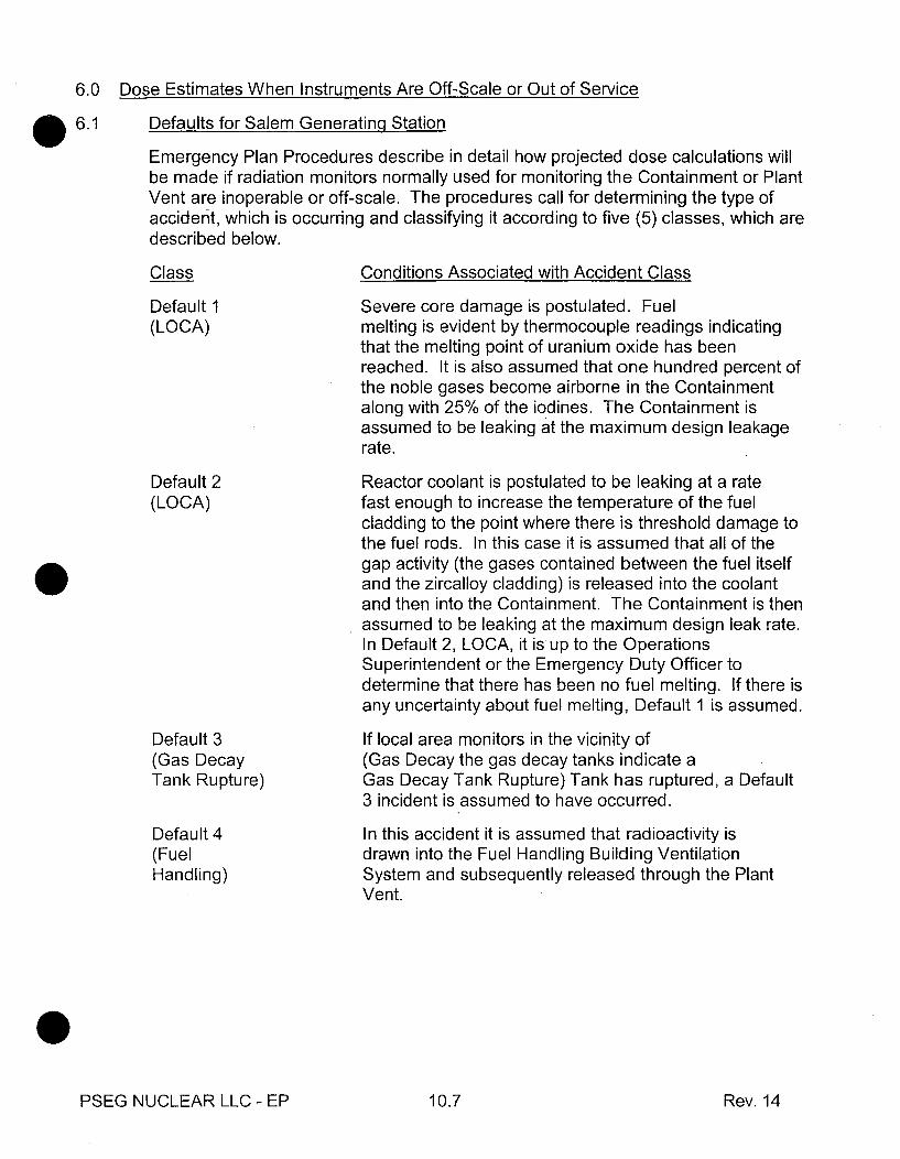
6.0 Dose Estimates When Instruments Are Off-Scale or Out of Service
6.1 Defaults for Salem Generating StationEmergency Plan Procedures describe in detail how projected dose calculations willbe made if radiation monitors normally used for monitoring the Containment or PlantVent are inoperable or off-scale. The procedures call for determining the type ofaccident, which is occurring and classifying it according to five (5) classes, which aredescribed below.
Class Conditions Associated with Accident Class
Default I Severe core damage is postulated. Fuel(LOCA) melting is evident by thermocouple readings indicating
that the melting point of uranium oxide has beenreached. It is also assumed that one hundred percent ofthe noble gases become airborne in the Containmentalong with 25% of the iodines. The Containment isassumed to be leaking at the maximum design leakagerate.
Default 2 Reactor coolant is postulated to be leaking at a rate(LOCA) fast enough to increase the temperature of the fuel
cladding to the point where there is threshold damage tothe fuel rods. In this case it is assumed that all of thegap activity (the gases contained between the fuel itselfand the zircalloy cladding) is released into the coolantand then into the Containment. The Containment is thenassumed to be leaking at the maximum design leak rate.In Default 2, LOCA, it is up to the OperationsSuperintendent or the Emergency Duty Officer todetermine that there has been no fuel melting. If there isany uncertainty about fuel melting, Default 1 is assumed.
Default 3 If local area monitors in the vicinity of(Gas Decay (Gas Decay the gas decay tanks indicate aTank Rupture) Gas Decay Tank Rupture) Tank has ruptured, a Default
3 incident is assumed to have occurred.
Default 4 In this accident it is assumed that radioactivity is(Fuel drawn into the Fuel Handling Building VentilationHandling) System and subsequently released through the Plant
Vent.
PSEG NUCLEAR LLC - EP 10.7 Rev. 14
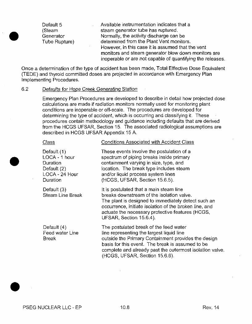
Default 5(SteamGeneratorTube Rupture)
Available instrumentation indicates that asteam generator tube has ruptured.Normally, the activity discharge can bedetermined from the Plant Vent monitors.However, in this case it is assumed that the ventmonitors and steam generator blow down monitors areinoperable or are not capable of quantifying the releases.
Once a determination of the type of accident has been made, Total Effective Dose Equivalent(TEDE) and thyroid committed doses are projected in accordance with Emergency PlanImplementing Procedures.
6.2 Defaults for Hope Creek Generatina Station
Emergency Plan Procedures are developed to describe in detail how projected dosecalculations are made if radiation monitors normally used for monitoring plantconditions are inoperable or off-scale. The procedures are developed fordetermining the type of accident, which is occurring and classifying it. Theseprocedures contain methodology and guidance including defaults that are derivedfrom the HCGS UFSAR, Section 15. The associated radiological assumptions aredescribed in HCGS UFSAR Appendix 15 A.
Class Conditions Associated with Accident Class
Default (1)LOCA - 1 hourDurationDefault (2)LOCA - 24 HourDuration
Default (3)Steam Line Break
Default (4)Feed water LineBreak
These events involve the postulation of aspectrum of piping breaks inside primarycontainment varying in size, type, andlocation. The break type includes steamand/or liquid process system lines(HCGS, UFSAR, Section 15.6.5).
It is postulated that a main steam linebreaks downstream of the isolation valve.The plant is designed to immediately detect such anoccurrence, initiate isolation of the broken line, andactuate the necessary protective features (HCGS,UFSAR, Section 15.6.4).
The postulated break of the feed waterline representing the largest liquid lineoutside the Primary Containment provides the designbasis for this event. The break is assumed to becomplete and already past the outermost isolation valve.(HCGS, UFSAR, Section 15.6.6).
PSEG NUCLEAR LLC - EP 10.8 Rev. 14

Default (5)OffgasTreatment
Default (6)Control RodDrop
Default (7)FuelHandlingAccident
Default (8)InstrumentLine failure
Dose Assessment From
A failure of an active component of thegaseous radwaste treatment system isassumed to occur. This event results in System Failurethe activity normally processed by the off gas systembeing released to the Turbine Building, and subsequentlyreleased through the ventilation system to theenvironment without treatment. (HCGS, UFSAR, Section15.7.1).
The radiological consequences of a controlrod drop accident (a design basisaccident) are Postulated in the HCGS UFSAR Appendix15 A, Section 15A. This postulated accident assumescladding failure of several hundred fuel rods, fuel meltinglocalized failure, and subsequent circumstances resultingin radiological releases. (HCGS, UFSAR, Section15.4.9).
The fuel handling accident is assumed tooccur as a consequence of a failure of thefuel assembly lifting mechanisms resultingin the dropping of a raised fuel assembly onto other fuelassemblies. A variety of events, which qualify for theclass of accidents termed "fuel handling accidents", wereinvestigated (HCGS, UFSAR, Section 15.7.4).
This event involves a postulated small break in asteam or liquid line inside or outside the PrimaryContainment but within the Reactor Building structure. Itis assumed that a small instrument line breaks at alocation where the break may not be able to be isolatedand where immediate detection is not automatic orapparent.
Field Monitorina - Salem-Hope Creek7.0
The Salem and Hope Creek Offsite Dose Calculation Manuals (ODCM's) summarizeEnvironmental Radiological Monitoring. Field monitoring within the plume exposureEPZ takes place whenever the radiological emergency response organization is fullyactivated. Field teams take direction from the radiological support personnel in theTSC and/or EOF. Data is obtained and updated quarter hourly and hourly on themeteorological variables of wind direction, speed and vertical temperature change(Delta T). This data is used to direct the onsite and offsite survey teams. Each fieldmonitoring team is capable of performing the necessary functions required to obtainreliable data. Communications are accomplished by the use of emergency radiosand cellular phones by each team. Deployment times range from 30 to 60 minutesfor the onsite and offsite emergency radiation survey team(s). Field monitoring isperformed in accordance with Emergency Plan Implementing Procedures.
PSEG NUCLEAR LLC - EP 10.9 Rev. 14
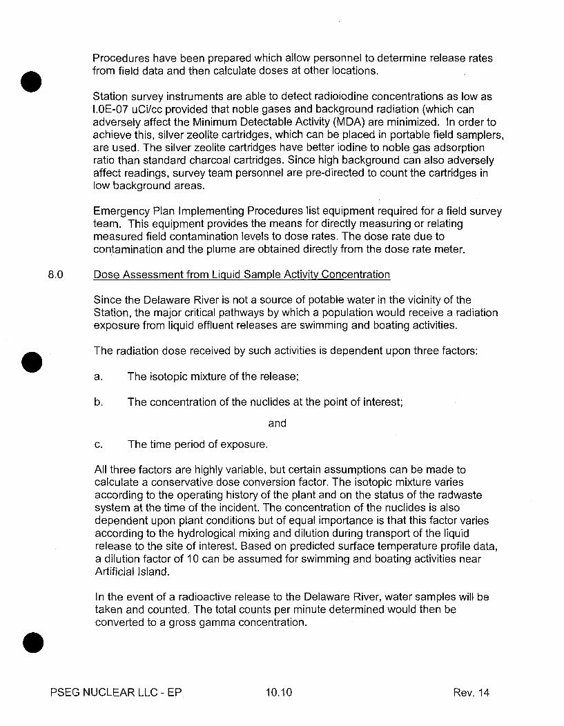
Procedures have been prepared which allow personnel to determine release ratesfrom field data and then calculate doses at other locations.
Station survey instruments are able to detect radioiodine concentrations as low as1.OE-07 uCi/cc provided that noble gases and background radiation (which canadversely affect the Minimum Detectable Activity (MDA) are minimized. In order toachieve this, silver zeolite cartridges, which can be placed in portable field samplers,are used. The silver zeolite cartridges have better iodine to noble gas adsorptionratio than standard charcoal cartridges. Since high background can also adverselyaffect readings, survey team personnel are pre-directed to count the cartridges inlow background areas.
Emergency Plan Implementing Procedures list equipment required for a field surveyteam. This equipment provides the means for directly measuring or relatingmeasured field contamination levels to dose rates. The dose rate due tocontamination and the plume are obtained directly from the dose rate meter.
8.0 Dose Assessment from Liquid Sample Activity Concentration
Since the Delaware River is not a source of potable water in the vicinity of theStation, the major critical pathways by which a population would receive a radiationexposure from liquid effluent releases are swimming and boating activities.
The radiation dose received by such activities is dependent upon three factors:
a. The isotopic mixture of the release;
b. The concentration of the nuclides at the point of interest;
and
c. The time period of exposure.
All three factors are highly variable, but certain assumptions can be made tocalculate a conservative dose conversion factor. The isotopic mixture variesaccording to the operating history of the plant and on the status of the radwastesystem at the time of the incident. The concentration of the nuclides is alsodependent upon plant conditions but of equal importance is that this factor variesaccording to the hydrological mixing and dilution during transport of the liquidrelease to the site of interest. Based on predicted surface temperature profile data,a dilution factor of 10 can be assumed for swimming and boating activities nearArtificial Island.
In the event of a radioactive release to the Delaware River, water samples will betaken and counted. The total counts per minute determined would then beconverted to a gross gamma concentration.
PSEG NUCLEAR LLC - EP 10.10 Rev. 14
8.1 Water Immersion (Swimming)
The radiation dose from water immersion (swimming) depends upon theconcentration of the nuclides present at the location of the immersion and theperiod of exposure. Dose rate conversion factors have been calculated on theassumption that the swimmer is completely submerged and surrounded on all sidesby a large volume of water. This physical arrangement approximates 4 7t geometryfor gamma radiation and 2 n for beta radiation.
8.2 Normalized Conversion Factors for Water Immersion and Boating
Based on a typical isotopic mixture, general dose equations can be formulatedwhich incorporate a weighted average dose rate conversion factor, a gross isotopicconcentration value, and the time period of exposure.
Based on sample analysis, exposure time, and the normalized conversion factors,dose can be calculated for any swimming or boating activities in the vicinity ofArtificial Island. A comparison would then be made of these calculated doses withState Action Levels as indicated in the State Radiological Emergency ResponsePlan for Nuclear Power Plants.
9.0 Other Onsite Emergency Equipment- Assessment
Onsite instrumentation, which can be used to initiate emergency measures, isdescribed in the implementing procedures of this plan.
9.1 Meteorological Monitoring
A meteorological program in accordance with the recommendation of NRCRegulatory Guide 1.23 "Onsite Meteorological Programs" and Section 2.3.3 ofNUREG 75/087 (Rev. 1) has been established.
The primary meteorological monitoring system measures wind speed and directionat three elevations (300 ft., 150 ft., and 33 ft.). Temperature difference is measuredbetween 300 ft. and 33 ft. and between 150 ft. and 33 ft., in order to provide verticallapse rates for air stability estimates. Calculated sigma theta values of the winddirection at the three elevations are also provided.
Backup meteorological data is provided by a backup tower located onsiteapproximately 500 ft. south of the primary meteorological tower. Backupmeteorological data is provided through wind speed and wind direction sensorsmounted on a ten-meter pole. In addition to the 15-minute averaged wind speed andwind direction, a computed sigma theta value is provided. The primary as well asthe backup meteorological information is available in the Control Rooms, Salem andHope Creek TSC, and the EOF.
PSEG NUCLEAR LLC - EP 10.11 Rev. 14

The meteorological monitoring system is provided with a dedicated battery backuppower supply. The system is calibrated quarterly using equipment traceable to anNBS Standard. The Meteorological Monitoring Program is reviewed biennually inaccordance with the Hope Creek and Salem UFSAR. (A detailed description of theonsite meteorological measurements program is provided in Section 2.3.3 of theHope Creek and Salem UFSARs).
A system to provide alternate remote interrogation of the meteorological system isavailable by way of direct telephone dial-up capability.
The Emergency Plan Implementing Procedures provide for meteorological supportfrom the closest NOAA Weather Station (National Weather Service-NWS).Information, including synoptic weather conditions, forecast, regional precipitationand severe weather alerts from this NWS station is available on a 24-hour-per-daybasis. Monthly communication checks with this NWS station are made inaccordance with Section 15.0 of this Plan. It has been determined that the datafrom this nearby NOAA weather station is representative of the combination of localand regional meteorology. Backup communication with this weather station usesthe Delaware NAWAS.
9.2 Seismic Monitoring
A Control Room alarm is provided in the event of seismic activity associated with theOperating Basis Earthquake (OBE). Seismic monitoring is performed using triaxialaccelographs (with a range of +lg and sensitivity of 0.01g) multi-channel recordersand response spectrum analyzers. Time history accelographs are placedthroughout the plant site. (A complete discussion of seismic instrumentation isprovided in Hope Creek UFSAR, Section 3.7.4. and Salem UFSAR, Section 3.7).
9.3 River Level Monitoring
River water levels at each service water pump sump, upstream of the intakestructure, are indicated at the Control Room. This system includes two (2) levelsensing elements, two (2) transmitting/recording channels, and a signal conditioner.
The geophysical instrumentation monitors the parameters required for evaluatingaction levels contained in the Event Classification Guide (ECG) and EmergencyPlan Implementing Procedures.
9.4 Fire Detection
Both station Fire Protection Systems are designed in general accordance with theNational Fire Protection Association's standards. Any fire initiates fire alarms andthe protection systems as appropriate. An alarm is initiated by automatic sprinkleractuation, smoke detector actuation, heat sensor actuation or by manual action.
PSEG NUCLEAR LLC - EP 10.12 Rev. 14
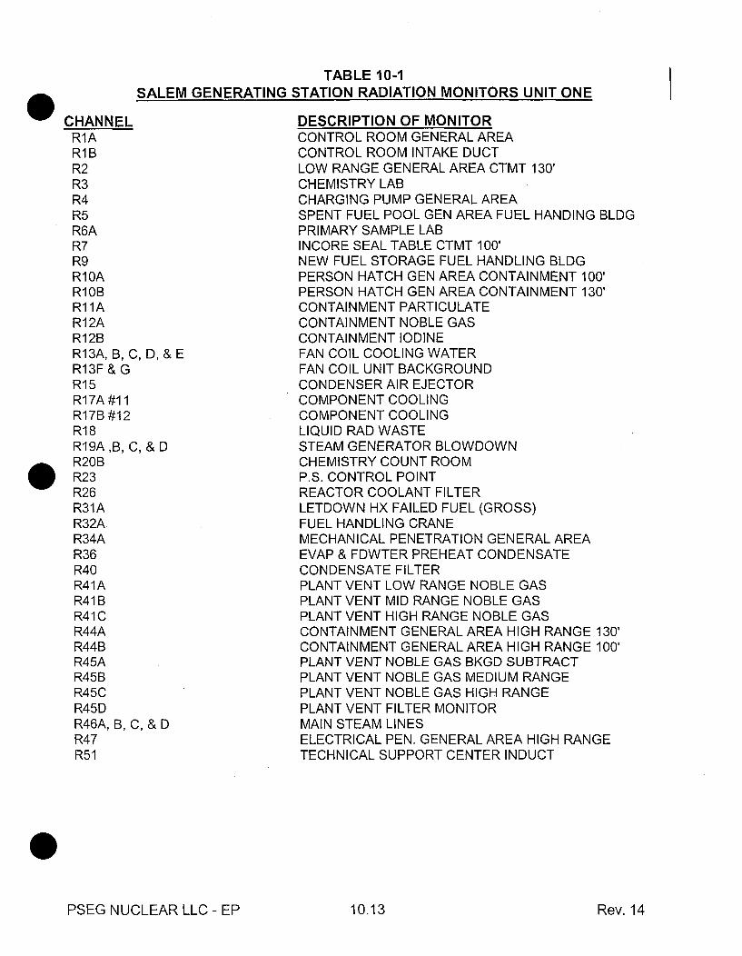
TABLE 10-1SALEM GENERATING STATION RADIATION MONITORS UNIT ONE
CHANNELR1AR1BR2R3R4R5R6AR7R9R1 OAR10BR11AR12AR1 2BR13A, B, C, D, & ER13F & GR15R17A #11R17B #12R18R19A,B, C, & DR20BR23R26R31AR32AR34AR36R40R41AR41 BR41CR44AR44BR45AR45BR45CR45DR46A, B, C, & DR47R51
DESCRIPTION OF MONITORCONTROL ROOM GENERAL AREACONTROL ROOM INTAKE DUCTLOW RANGE GENERAL AREA CTMT 130'CHEMISTRY LABCHARGING PUMP GENERAL AREASPENT FUEL POOL GEN AREA FUEL HANDING BLDGPRIMARY SAMPLE LABINCORE SEAL TABLE CTMT 100'NEW FUEL STORAGE FUEL HANDLING BLDGPERSON HATCH GEN AREA CONTAINMENT 100'PERSON HATCH GEN AREA CONTAINMENT 130'CONTAINMENT PARTICULATECONTAINMENT NOBLE GASCONTAINMENT IODINEFAN COIL COOLING WATERFAN COIL UNIT BACKGROUNDCONDENSER AIR EJECTORCOMPONENT COOLINGCOMPONENT COOLINGLIQUID RAD WASTESTEAM GENERATOR BLOWDOWNCHEMISTRY COUNT ROOMP.S. CONTROL POINTREACTOR COOLANT FILTERLETDOWN HX FAILED FUEL (GROSS)FUEL HANDLING CRANEMECHANICAL PENETRATION GENERAL AREAEVAP & FDWTER PREHEAT CONDENSATECONDENSATE FILTERPLANT VENT LOW RANGE NOBLE GASPLANT VENT MID RANGE NOBLE GASPLANT VENT HIGH RANGE NOBLE GASCONTAINMENT GENERAL AREA HIGH RANGE 130'CONTAINMENT GENERAL AREA HIGH RANGE 100'PLANT VENT NOBLE GAS BKGD SUBTRACTPLANT VENT NOBLE GAS MEDIUM RANGEPLANT VENT NOBLE GAS HIGH RANGEPLANT VENT FILTER MONITORMAIN STEAM LINESELECTRICAL PEN. GENERAL AREA HIGH RANGETECHNICAL SUPPORT CENTER INDUCT
PSEG NUCLEAR LLC - EP 10.13 Rev. 14

TABLE 10-1 (cont.)SALEM GENERATING STATION RADIATION MONITORS UNIT TWO
CHANNELR1AR1BR2R4R5R7R9R10ARi OBR11AR12AR12BR13A, B, & CR15R17A & BR18R19A, B, C, & DR26R31R32AR34R37R40R41AR41 BR41CR44AR44BR45AR45BR45CR45DR46A, B, C, & DR47R52R53A, B, C, & D
DESCRIPTION OF MONITORCONTROL ROOM GENERAL AREACONTROL ROOM INTAKE DUCTLOW RANGE GENERAL AREA CTMT 130'CHARGING PUMP GENERAL AREASPENT FUEL POOL GENERAL AREAINCORE SEAL TABLE CTMT 100'NEW FUEL STORAGEPERSONNEL HATCH GENERAL AREA CTMT 100'PERSONNEL HATCH GENERAL AREA CTMT 130'CONTAINMENT PARTICULATECONTAINMENT NOBLE GASCONTAINMENT IODINEFAN COIL COOLING WATERCONDENSER AIR EJECTOR#21 & 22 COMPONENT COOLINGLIQUID RAD WASTESTEAM GENERATOR BLOWDOWNREACTOR COOLANT FILTERLETDOWN HX FAILED FUELFUEL HANDLING CRANEMECHANICAL PENETRATION GENERAL AREANON-RADIOACTIVE LIQUID WASTE BASINCONDENSATE FILTERPLANT VENT LOW RANGE NOBLE GASPLANT VENT MID RANGE NOBLE GASPLANT VENT HIGH RANGE NOBLE GASCONTAINMENT GENERAL AREA HIGH RANGE 130'CONTAINMENT GENERAL AREA HIGH RANGE 100'PLANT VENT NOBLE GAS BKGD SUBTRACTPLANT VENT NOBLE GAS MEDIUM RANGEPLANT VENT NOBLE GAS HIGH RANGEPLANT VENT FILTER MONITORMAIN STEAM LINESELECTRICAL PEN. GENERAL AREA HIGH RANGEPASS RM (LOCAL)N16 MAIN STEAMLINE MONITOR
PSEG NUCLEAR LLC - EP 10.14 Rev. 14

TABLE 10-2HOPE CREEK GENERATING STATION RADIATION MONITORS
CHANNEL9RX5009RX5019RX5039RX5059RX5069RX5079RX5089RX5099RX5109RX5119RX5129RX5169RX5179RX5189RX5809RX5819RX5909RX5919RX5989RX5999RX6029RX6039RX6069RX6079RX61 09RX6119RX6129RX6139RX6149RX6159RX6169RX6179RX6189RX6199RX6209RX6219RX6229RX6259RX6269RX6279RX6289RX6299RX6309RX6319RX6329RX6339RX634
DESCRIPTION OF MONITORRACSSACS ASACS BTBCWCTB MEAS. CONC.DLD RMSLIQ. RADWASTEMSL AMSL BMSL CMSL DHTV N/G LOWHTV N/G HIGHHTV EFFSPV EFFSPV N/G HIGHNPV EFFNPV N/G HIGHCTB CALC CONCCTB EFFNPV N/G LOWNPV N/G MIDSPV N/G LOWSPV N/G MIDFRVS N/G MIDFRVS N/G HIGHNFS ANFS BRX. BLDG. VENT. EXH.TB. BLDG. EXH.RADW. EXH. SYS.GAS. RADW. AREA EXH.TB. BLDG. COMP. EXH.RADW. AREA EXH.TECH. SUP. CTR.OFFGAS AOFFGAS BOFFGAS TREATED AOFFGAS TREATED BRFE ARFE BRFE CCRV CCRV ClRBE ARBE BRBE C
PSEG NUCLEAR LLC - EP 10.15 Rev. 14

TABLE 10-2 (cont.)HOPE CREEK GENERATING STATION RADIATION MONITORS
CHANNEL9RX6359RX6369RX6379RX6389RX6409RX6809RX6989RX6999RX7009RX7019RX7029RX7039RX7049RX7059RX7069RX7079RX7089RX7099RX7109RX7119RX7129RX7139RX7149RX7159RX7169RX7179RX7209RX7219RX7229RX7239RX7249RX7209RX7219RX7229RX7239RX724
DESCRIPTION OF MONITORDAPA ADAPA BCRV DCRV DlFRVS N/G LOWFRVS EFFOUTER TIP RM ARMINNER TIP RM ARMPERS. AIRL.MDT. EQPT. HATCHOPEN EQPT. HATCH 145'OPEN EQPT. HATCH 162'SAFEG. INST. RM.EQPT. AIRLOCKRCDSESPENT FUEL SPRBSSRADW. DRUM SHIP AREAMAIN CRCHEM. LAB. SPL.AUX. HATCHWAYRESTR. MS. 1RESTR. MS. 2TECH. SUP. CTR. INLET.OG VIAL SAMP. STA.RADW SAMP. STA.FRVS LRPFRVS SKIDLIQ. RADW. CRORBSSOFFGAS CRFRVS LRPFRVS SKIDLIQ. RADW. CRORBSSOFFGAS CR
0
PSEG NUCLEAR LLC - EP 10.16 Rev. 14