documentation ek1110, ek1110-0008 - beckhoff · foreword ek1110, ek1110-0008 version: 2.35 1...
TRANSCRIPT

Documentation
EK1110, EK1110-0008
EtherCAT Extension
2.32018-11-28
Version:Date:

Table of contents
EK1110, EK1110-0008 3Version: 2.3
Table of contents1 Foreword .................................................................................................................................................... 5
1.1 Notes on the documentation.............................................................................................................. 51.2 Safety instructions ............................................................................................................................. 61.3 Documentation issue status .............................................................................................................. 71.4 Version identification of EtherCAT devices ....................................................................................... 7
2 Product overview..................................................................................................................................... 122.1 Introduction...................................................................................................................................... 122.2 Technical data ................................................................................................................................. 132.3 Start ................................................................................................................................................. 13
3 Basics communication ........................................................................................................................... 143.1 System properties............................................................................................................................ 143.2 EtherCAT basics.............................................................................................................................. 173.3 EtherCAT cabling – wire-bound....................................................................................................... 173.4 EtherCAT State Machine................................................................................................................. 183.5 CoE - Interface: notes...................................................................................................................... 193.6 Distributed Clock ............................................................................................................................. 19
4 Mounting and wiring................................................................................................................................ 204.1 M8 Connector Cabling..................................................................................................................... 204.2 Nut torque for connectors ................................................................................................................ 224.3 Installation on mounting rails ........................................................................................................... 224.4 Installation instructions for enhanced mechanical load capacity ..................................................... 244.5 Installation positions ........................................................................................................................ 254.6 Connection system .......................................................................................................................... 274.7 Positioning of passive Terminals ..................................................................................................... 304.8 ATEX - Special conditions (standard temperature range) ............................................................... 314.9 ATEX - Special conditions (extended temperature range) .............................................................. 324.10 ATEX Documentation ...................................................................................................................... 334.11 UL notice ......................................................................................................................................... 33
5 Commissioning........................................................................................................................................ 355.1 EK1110 - Configuration by means of the TwinCAT System Manager............................................. 35
6 Error handling and diagnostics.............................................................................................................. 376.1 Diagnostic LED................................................................................................................................ 37
7 Appendix .................................................................................................................................................. 387.1 EtherCAT AL Status Codes............................................................................................................. 387.2 Firmware compatibility ..................................................................................................................... 387.3 Firmware Update EL/ES/EM/EPxxxx .............................................................................................. 38
7.3.1 Device description ESI file/XML....................................................................................... 397.3.2 Firmware explanation ...................................................................................................... 427.3.3 Updating controller firmware *.efw................................................................................... 437.3.4 FPGA firmware *.rbf......................................................................................................... 447.3.5 Simultaneous updating of several EtherCAT devices...................................................... 48
7.4 Support and Service ........................................................................................................................ 49
Table of contents
EK1110, EK1110-00084 Version: 2.3

Foreword
EK1110, EK1110-0008 5Version: 2.3
1 Foreword
1.1 Notes on the documentation
Intended audience
This description is only intended for the use of trained specialists in control and automation engineering whoare familiar with the applicable national standards.It is essential that the documentation and the following notes and explanations are followed when installingand commissioning these components.It is the duty of the technical personnel to use the documentation published at the respective time of eachinstallation and commissioning.
The responsible staff must ensure that the application or use of the products described satisfy all therequirements for safety, including all the relevant laws, regulations, guidelines and standards.
Disclaimer
The documentation has been prepared with care. The products described are, however, constantly underdevelopment.
We reserve the right to revise and change the documentation at any time and without prior announcement.
No claims for the modification of products that have already been supplied may be made on the basis of thedata, diagrams and descriptions in this documentation.
Trademarks
Beckhoff®, TwinCAT®, EtherCAT®, EtherCAT P®, Safety over EtherCAT®, TwinSAFE®, XFC® and XTS® areregistered trademarks of and licensed by Beckhoff Automation GmbH.Other designations used in this publication may be trademarks whose use by third parties for their ownpurposes could violate the rights of the owners.
Patent Pending
The EtherCAT Technology is covered, including but not limited to the following patent applications andpatents: EP1590927, EP1789857, DE102004044764, DE102007017835 with corresponding applications orregistrations in various other countries.
The TwinCAT Technology is covered, including but not limited to the following patent applications andpatents: EP0851348, US6167425 with corresponding applications or registrations in various other countries.
EtherCAT® is registered trademark and patented technology, licensed by Beckhoff Automation GmbH,Germany.
Copyright
© Beckhoff Automation GmbH & Co. KG, Germany.The reproduction, distribution and utilization of this document as well as the communication of its contents toothers without express authorization are prohibited.Offenders will be held liable for the payment of damages. All rights reserved in the event of the grant of apatent, utility model or design.
Foreword
EK1110, EK1110-00086 Version: 2.3
1.2 Safety instructions
Safety regulations
Please note the following safety instructions and explanations!Product-specific safety instructions can be found on following pages or in the areas mounting, wiring,commissioning etc.
Exclusion of liability
All the components are supplied in particular hardware and software configurations appropriate for theapplication. Modifications to hardware or software configurations other than those described in thedocumentation are not permitted, and nullify the liability of Beckhoff Automation GmbH & Co. KG.
Personnel qualification
This description is only intended for trained specialists in control, automation and drive engineering who arefamiliar with the applicable national standards.
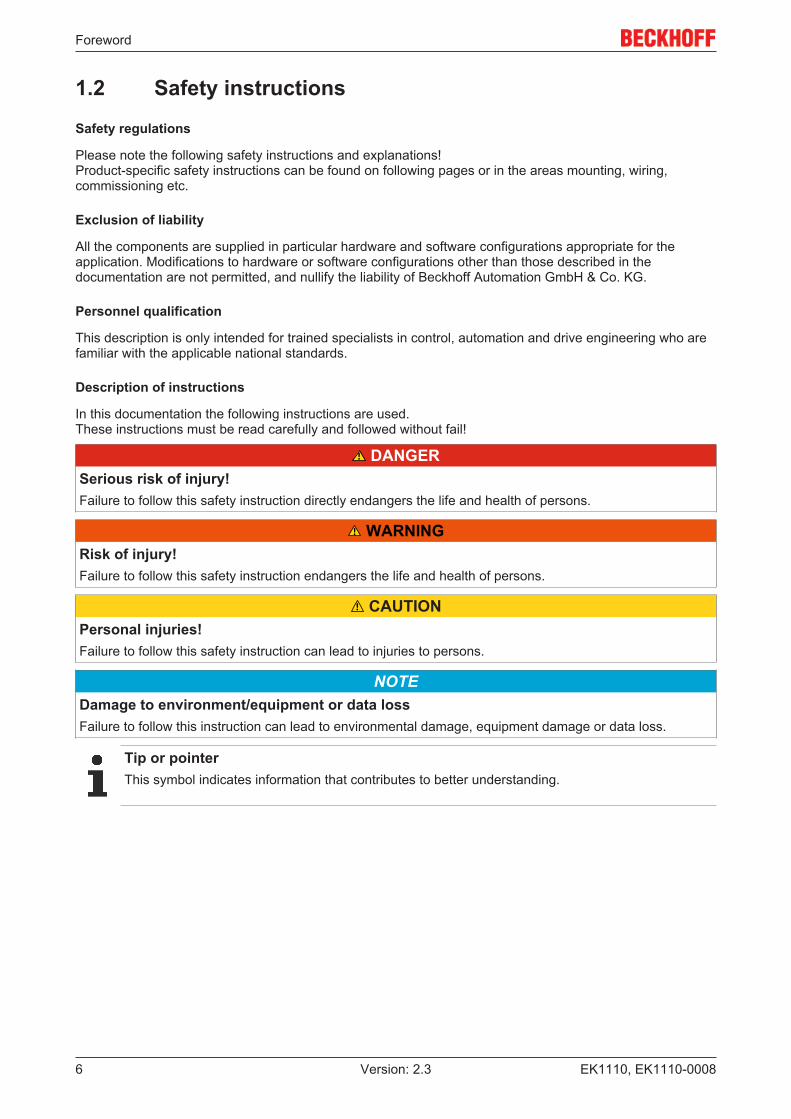
Description of instructions
In this documentation the following instructions are used. These instructions must be read carefully and followed without fail!
DANGERSerious risk of injury!Failure to follow this safety instruction directly endangers the life and health of persons.
WARNINGRisk of injury!Failure to follow this safety instruction endangers the life and health of persons.
CAUTIONPersonal injuries!Failure to follow this safety instruction can lead to injuries to persons.
NOTEDamage to environment/equipment or data lossFailure to follow this instruction can lead to environmental damage, equipment damage or data loss.
Tip or pointerThis symbol indicates information that contributes to better understanding.
Foreword
EK1110, EK1110-0008 7Version: 2.3
1.3 Documentation issue statusVersion Modifications2.3 • Technical data added
• Update structure2.2 • Technical data added
• Update structure2.1 • Addenda of EK1110-00082.0 • Migration1.4 • Technical data added
• Addenda chapter "Installation instructions for enhanced mechanical load capacity"1.3 • Technical data added
• Update structure1.2 • Technical data added1.1 • Technical data adapted1.0 • Technical data added0.1 • First preliminary version
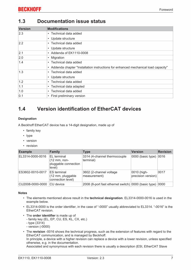
1.4 Version identification of EtherCAT devices
Designation
A Beckhoff EtherCAT device has a 14-digit designation, made up of
• family key• type• version• revision
Example Family Type Version RevisionEL3314-0000-0016 EL terminal
(12 mm, non-pluggable connectionlevel)
3314 (4-channel thermocoupleterminal)
0000 (basic type) 0016
ES3602-0010-0017 ES terminal(12 mm, pluggableconnection level)
3602 (2-channel voltagemeasurement)
0010 (high-precision version)
0017
CU2008-0000-0000 CU device 2008 (8-port fast ethernet switch) 0000 (basic type) 0000
Notes• The elements mentioned above result in the technical designation. EL3314-0000-0016 is used in the
example below.• EL3314-0000 is the order identifier, in the case of “-0000” usually abbreviated to EL3314. “-0016” is the
EtherCAT revision.• The order identifier is made up of
- family key (EL, EP, CU, ES, KL, CX, etc.)- type (3314)- version (-0000)
• The revision -0016 shows the technical progress, such as the extension of features with regard to theEtherCAT communication, and is managed by Beckhoff.In principle, a device with a higher revision can replace a device with a lower revision, unless specifiedotherwise, e.g. in the documentation.Associated and synonymous with each revision there is usually a description (ESI, EtherCAT Slave

Foreword
EK1110, EK1110-00088 Version: 2.3
Information) in the form of an XML file, which is available for download from the Beckhoff web site. From 2014/01 the revision is shown on the outside of the IP20 terminals, see Fig. “EL5021 EL terminal,standard IP20 IO device with batch number and revision ID (since 2014/01)”.
• The type, version and revision are read as decimal numbers, even if they are technically saved inhexadecimal.
Identification number
Beckhoff EtherCAT devices from the different lines have different kinds of identification numbers:
Production lot/batch number/serial number/date code/D number
The serial number for Beckhoff IO devices is usually the 8-digit number printed on the device or on a sticker.The serial number indicates the configuration in delivery state and therefore refers to a whole productionbatch, without distinguishing the individual modules of a batch.
Structure of the serial number: KK YY FF HH
KK - week of production (CW, calendar week)YY - year of productionFF - firmware versionHH - hardware version
Example with Ser. no.: 12063A02: 12 - production week 12 06 - production year 2006 3A - firmware version 3A 02 -hardware version 02
Exceptions can occur in the IP67 area, where the following syntax can be used (see respective devicedocumentation):
Syntax: D ww yy x y z u
D - prefix designationww - calendar weekyy - yearx - firmware version of the bus PCBy - hardware version of the bus PCBz - firmware version of the I/O PCBu - hardware version of the I/O PCB
Example: D.22081501 calendar week 22 of the year 2008 firmware version of bus PCB: 1 hardware versionof bus PCB: 5 firmware version of I/O PCB: 0 (no firmware necessary for this PCB) hardware version of I/OPCB: 1
Unique serial number/ID, ID number
In addition, in some series each individual module has its own unique serial number.
See also the further documentation in the area
• IP67: EtherCAT Box
• Safety: TwinSafe• Terminals with factory calibration certificate and other measuring terminals
Foreword
EK1110, EK1110-0008 9Version: 2.3
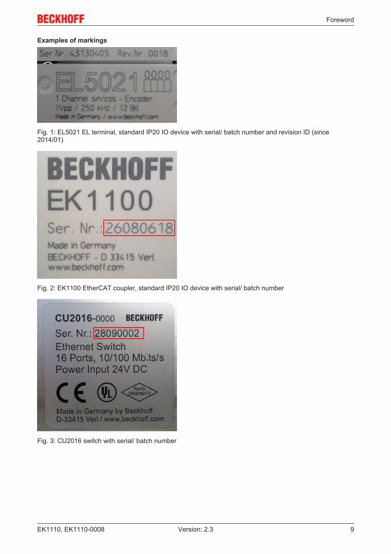
Examples of markings
Fig. 1: EL5021 EL terminal, standard IP20 IO device with serial/ batch number and revision ID (since2014/01)
Fig. 2: EK1100 EtherCAT coupler, standard IP20 IO device with serial/ batch number
Fig. 3: CU2016 switch with serial/ batch number
Foreword
EK1110, EK1110-000810 Version: 2.3
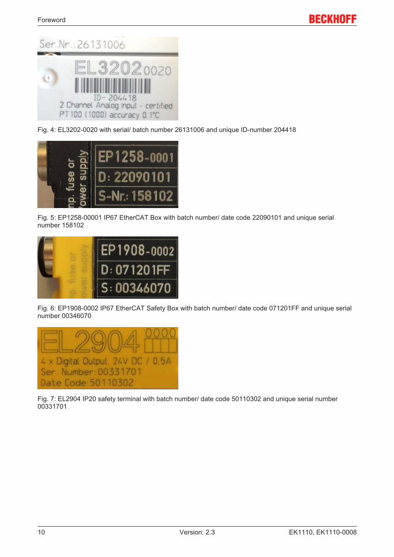
Fig. 4: EL3202-0020 with serial/ batch number 26131006 and unique ID-number 204418
Fig. 5: EP1258-00001 IP67 EtherCAT Box with batch number/ date code 22090101 and unique serialnumber 158102
Fig. 6: EP1908-0002 IP67 EtherCAT Safety Box with batch number/ date code 071201FF and unique serialnumber 00346070
Fig. 7: EL2904 IP20 safety terminal with batch number/ date code 50110302 and unique serial number00331701
Foreword
EK1110, EK1110-0008 11Version: 2.3
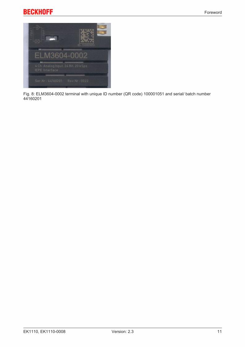
Fig. 8: ELM3604-0002 terminal with unique ID number (QR code) 100001051 and serial/ batch number44160201
Product overview
EK1110, EK1110-000812 Version: 2.3
2 Product overview
2.1 Introduction
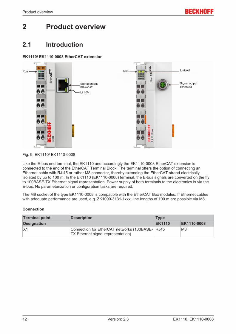
EK1110/ EK1110-0008 EtherCAT extension
Fig. 9: EK1110/ EK1110-0008
Like the E-bus end terminal, the EK1110 and accordingly the EK1110-0008 EtherCAT extension isconnected to the end of the EtherCAT Terminal Block. The terminal offers the option of connecting anEthernet cable with RJ 45 or rather M8 connector, thereby extending the EtherCAT strand electricallyisolated by up to 100 m. In the EK1110 (EK1110-0008) terminal, the E-bus signals are converted on the flyto 100BASE-TX Ethernet signal representation. Power supply of both terminals to the electronics is via theE-bus. No parameterization or configuration tasks are required.
The M8 socket of the type EK1110-0008 is compatible with the EtherCAT Box modules. If Ethernet cableswith adequate performance are used, e.g. ZK1090-3131-1xxx, line lengths of 100 m are possible via M8.
Connection
Terminal point Description TypeDesignation EK1110 EK1110-0008X1 Connection for EtherCAT networks (100BASE-
TX Ethernet signal representation)RJ45 M8

Product overview
EK1110, EK1110-0008 13Version: 2.3
2.2 Technical dataTechnical data EK1110 EK1110-0008Task in the EtherCAT system Conversion of the E-bus signals to 100BASE-TX Ethernet for
extension of the EtherCAT networkTransmission medium Ethernet CAT 5 cable (shielded)Cable length between two Bus Couplers max. 100 m (100BASE-TX)Protocol / Baud rate any EtherCAT protocol / 100 MbaudDelay approx. 1 µsConfiguration no address and configuration settings requiredBus connection 1 x RJ45 1 x M8, shielded, screw typePower supply from E-busCurrent consumption typ. 130 mADielectric strength 500 V (supply voltage/EtherCAT)Dimensions (W x H x D) approx. 44 mm x 100 mm x 68 mmWeight approx. 50 gPermissible ambient temperature rangeduring operation
-25°C ... +60°C(extended temperature range)
Permissible ambient temperature rangeduring storage
-40°C ... + 85°C
Permissible relative humidity 95%, no condensationMounting [} 22] on 35 mm mounting rail conforms to EN 60715Vibration/shock resistance conforms to EN 60068-2-6 / EN 60068-2-27,
see also installation instructions [} 24] for enhanced mechanicalload capacity
EMC immunity/emission conforms to EN 61000-6-2 / EN 61000-6-4Protection class IP20Installation position variableApproval CE
ATEX [} 32]cULus [} 33]
2.3 StartFor commissioning:
• mount the EK1110 as described in the chapter Mounting and wiring [} 20]
• configure the EK1110 in TwinCAT as described in chapter Parameterization and commissioning[} 35].
Basics communication
EK1110, EK1110-000814 Version: 2.3
3 Basics communication
3.1 System properties
Protocol
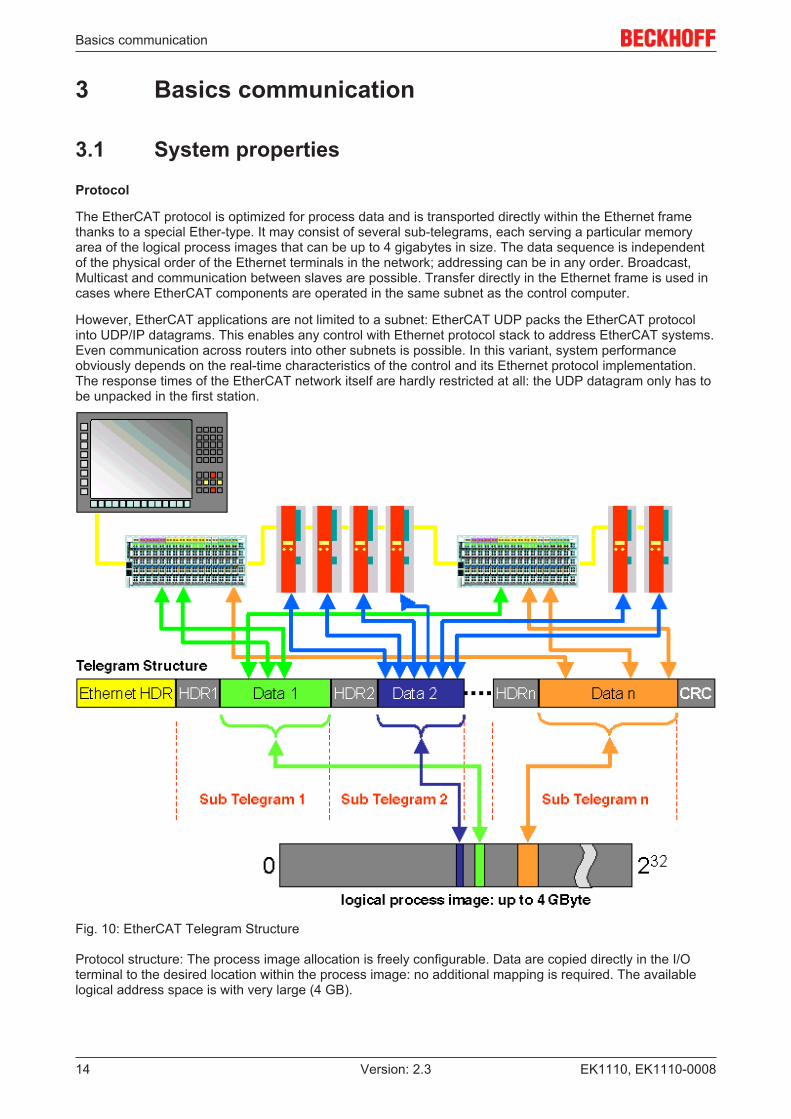
The EtherCAT protocol is optimized for process data and is transported directly within the Ethernet framethanks to a special Ether-type. It may consist of several sub-telegrams, each serving a particular memoryarea of the logical process images that can be up to 4 gigabytes in size. The data sequence is independentof the physical order of the Ethernet terminals in the network; addressing can be in any order. Broadcast,Multicast and communication between slaves are possible. Transfer directly in the Ethernet frame is used incases where EtherCAT components are operated in the same subnet as the control computer.
However, EtherCAT applications are not limited to a subnet: EtherCAT UDP packs the EtherCAT protocolinto UDP/IP datagrams. This enables any control with Ethernet protocol stack to address EtherCAT systems.Even communication across routers into other subnets is possible. In this variant, system performanceobviously depends on the real-time characteristics of the control and its Ethernet protocol implementation.The response times of the EtherCAT network itself are hardly restricted at all: the UDP datagram only has tobe unpacked in the first station.
Fig. 10: EtherCAT Telegram Structure
Protocol structure: The process image allocation is freely configurable. Data are copied directly in the I/Oterminal to the desired location within the process image: no additional mapping is required. The availablelogical address space is with very large (4 GB).
Basics communication
EK1110, EK1110-0008 15Version: 2.3
Topology
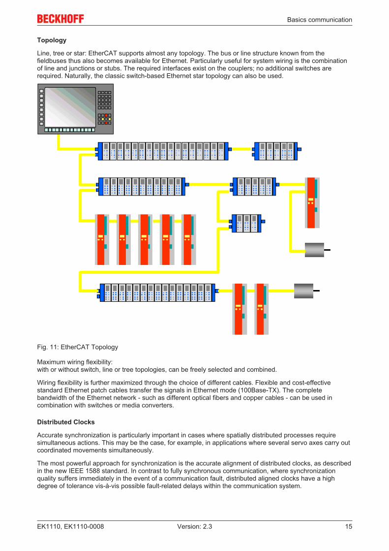
Line, tree or star: EtherCAT supports almost any topology. The bus or line structure known from thefieldbuses thus also becomes available for Ethernet. Particularly useful for system wiring is the combinationof line and junctions or stubs. The required interfaces exist on the couplers; no additional switches arerequired. Naturally, the classic switch-based Ethernet star topology can also be used.
Fig. 11: EtherCAT Topology
Maximum wiring flexibility:with or without switch, line or tree topologies, can be freely selected and combined.
Wiring flexibility is further maximized through the choice of different cables. Flexible and cost-effectivestandard Ethernet patch cables transfer the signals in Ethernet mode (100Base-TX). The completebandwidth of the Ethernet network - such as different optical fibers and copper cables - can be used incombination with switches or media converters.
Distributed Clocks
Accurate synchronization is particularly important in cases where spatially distributed processes requiresimultaneous actions. This may be the case, for example, in applications where several servo axes carry outcoordinated movements simultaneously.
The most powerful approach for synchronization is the accurate alignment of distributed clocks, as describedin the new IEEE 1588 standard. In contrast to fully synchronous communication, where synchronizationquality suffers immediately in the event of a communication fault, distributed aligned clocks have a highdegree of tolerance vis-à-vis possible fault-related delays within the communication system.
Basics communication
EK1110, EK1110-000816 Version: 2.3
With EtherCAT, the data exchange is fully based on a pure hardware machine. Since the communicationutilizes a logical (and thanks to full-duplex Fast Ethernet also physical) ring structure, the mother clock candetermine the run-time offset to the individual daughter clocks simply and accurately - and vice versa. Thedistributed clocks are adjusted based on this value, which means that a very precise network-wide timebasewith a jitter of significantly less than 1 microsecond is available.
However, high-resolution distributed clocks are not only used for synchronization, but can also provideaccurate information about the local timing of the data acquisition. For example, controls frequently calculatevelocities from sequentially measured positions. Particularly with very short sampling times, even a smalltemporal jitter in the displacement measurement leads to large step changes in velocity. With EtherCAT new,extended data types are introduced as a logical extension (time stamp and oversampling data type). Thelocal time is linked to the measured value with a resolution of up to 10 ns, which is made possible by thelarge bandwidth offered by Ethernet. The accuracy of a velocity calculation then no longer depends on thejitter of the communication system. It is orders of magnitude better than that of measuring techniques basedon jitter-free communication.
Performance
EtherCAT reaches new dimensions in network performance. Protocol processing is purely hardware-basedthrough an FMMU chip in the terminal and DMA access to the network card of the master. It is thusindependent of protocol stack run-times, CPU performance and software implementation. The update timefor 1000 I/Os is only 30 µs - including terminal cycle time. Up to 1486 bytes of process data can beexchanged with a single Ethernet frame - this is equivalent to almost 12000 digital inputs and outputs. Thetransfer of this data quantity only takes 300 µs.
The communication with 100 servo axes only takes 100 µs. During this time, all axes are provided with setvalues and control data and report their actual position and status. Distributed clocks enable the axes to besynchronized with a deviation of significantly less than 1 microsecond.
The extremely high performance of the EtherCAT technology enables control concepts that could not berealized with classic fieldbus systems. For example, the Ethernet system can now not only deal with velocitycontrol, but also with the current control of distributed drives. The tremendous bandwidth enables statusinformation to be transferred with each data item. With EtherCAT, a communication technology is availablethat matches the superior computing power of modern Industrial PCs. The bus system is no longer thebottleneck of the control concept. Distributed I/Os are recorded faster than is possible with most local I/Ointerfaces. The EtherCAT technology principle is scalable and not bound to the baud rate of 100 Mbaud –extension to Gbit Ethernet is possible.
Diagnostics
Experience with fieldbus systems shows that availability and commissioning times crucially depend on thediagnostic capability. Only faults that are detected quickly and accurately and which can be precisely locatedcan be corrected quickly. Therefore, special attention was paid to exemplary diagnostic features during thedevelopment of EtherCAT.
During commissioning, the actual configuration of the I/O terminals should be checked for consistency withthe specified configuration. The topology should also match the saved configuration. Due to the built-intopology recognition down to the individual terminals, this verification can not only take place during systemstart-up, automatic reading in of the network is also possible (configuration upload).
Bit faults during the transfer are reliably detected through evaluation of the CRC checksum: The 32 bit CRCpolynomial has a minimum hamming distance of 4. Apart from breaking point detection and localization, theprotocol, physical transfer behavior and topology of the EtherCAT system enable individual qualitymonitoring of each individual transmission segment. The automatic evaluation of the associated errorcounters enables precise localization of critical network sections. Gradual or changing sources of error suchas EMC influences, defective push-in connectors or cable damage are detected and located, even if they donot yet overstrain the self-healing capacity of the network.
Integration of standard Bus Terminals from Beckhoff
In addition to the new Bus Terminals with E-Bus connection (ELxxxx), all Bus Terminals from the familiarstandard range with K-bus connection (KLxxxx) can be connected via the BK1120 or BK1250 Bus Coupler.This ensures compatibility and continuity with the existing Beckhoff Bus Terminal systems. Existinginvestments are protected.
Basics communication
EK1110, EK1110-0008 17Version: 2.3
3.2 EtherCAT basicsPlease refer to the EtherCAT System Documentation for the EtherCAT fieldbus basics.
3.3 EtherCAT cabling – wire-boundThe cable length between two EtherCAT devices must not exceed 100 m. This results from the FastEthernettechnology, which, above all for reasons of signal attenuation over the length of the cable, allows a maximumlink length of 5 + 90 + 5 m if cables with appropriate properties are used. See also the Designrecommendations for the infrastructure for EtherCAT/Ethernet.
Cables and connectors
For connecting EtherCAT devices only Ethernet connections (cables + plugs) that meet the requirements ofat least category 5 (CAt5) according to EN 50173 or ISO/IEC 11801 should be used. EtherCAT uses 4 wiresfor signal transfer.
EtherCAT uses RJ45 plug connectors, for example. The pin assignment is compatible with the Ethernetstandard (ISO/IEC 8802-3).
Pin Color of conductor Signal Description1 yellow TD + Transmission Data +2 orange TD - Transmission Data -3 white RD + Receiver Data +6 blue RD - Receiver Data -
Due to automatic cable detection (auto-crossing) symmetric (1:1) or cross-over cables can be used betweenEtherCAT devices from Beckhoff.
Recommended cablesSuitable cables for the connection of EtherCAT devices can be found on the Beckhoff website!
E-Bus supply
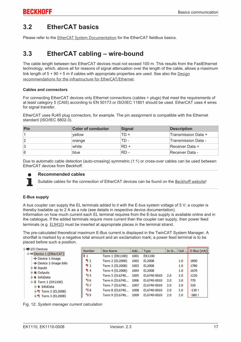
A bus coupler can supply the EL terminals added to it with the E-bus system voltage of 5 V; a coupler isthereby loadable up to 2 A as a rule (see details in respective device documentation).Information on how much current each EL terminal requires from the E-bus supply is available online and inthe catalogue. If the added terminals require more current than the coupler can supply, then power feedterminals (e.g. EL9410) must be inserted at appropriate places in the terminal strand.
The pre-calculated theoretical maximum E-Bus current is displayed in the TwinCAT System Manager. Ashortfall is marked by a negative total amount and an exclamation mark; a power feed terminal is to beplaced before such a position.
Fig. 12: System manager current calculation

Basics communication
EK1110, EK1110-000818 Version: 2.3
NOTEMalfunction possible!The same ground potential must be used for the E-Bus supply of all EtherCAT terminals in a terminal block!
3.4 EtherCAT State MachineThe state of the EtherCAT slave is controlled via the EtherCAT State Machine (ESM). Depending upon thestate, different functions are accessible or executable in the EtherCAT slave. Specific commands must besent by the EtherCAT master to the device in each state, particularly during the bootup of the slave.
A distinction is made between the following states:
• Init• Pre-Operational• Safe-Operational and• Operational• Boot
The regular state of each EtherCAT slave after bootup is the OP state.
Fig. 13: States of the EtherCAT State Machine
Init
After switch-on the EtherCAT slave in the Init state. No mailbox or process data communication is possible.The EtherCAT master initializes sync manager channels 0 and 1 for mailbox communication.
Pre-Operational (Pre-Op)
During the transition between Init and Pre-Op the EtherCAT slave checks whether the mailbox was initializedcorrectly.
In Pre-Op state mailbox communication is possible, but not process data communication. The EtherCATmaster initializes the sync manager channels for process data (from sync manager channel 2), the FMMUchannels and, if the slave supports configurable mapping, PDO mapping or the sync manager PDOassignment. In this state the settings for the process data transfer and perhaps terminal-specific parametersthat may differ from the default settings are also transferred.

Basics communication
EK1110, EK1110-0008 19Version: 2.3
Safe-Operational (Safe-Op)
During transition between Pre-Op and Safe-Op the EtherCAT slave checks whether the sync managerchannels for process data communication and, if required, the distributed clocks settings are correct. Beforeit acknowledges the change of state, the EtherCAT slave copies current input data into the associated DP-RAM areas of the EtherCAT slave controller (ECSC).
In Safe-Op state mailbox and process data communication is possible, although the slave keeps its outputsin a safe state, while the input data are updated cyclically.
Outputs in SAFEOP stateThe default set watchdog monitoring sets the outputs of the module in a safe state - depending onthe settings in SAFEOP and OP - e.g. in OFF state. If this is prevented by deactivation of the watch-dog monitoring in the module, the outputs can be switched or set also in the SAFEOP state.
Operational (Op)
Before the EtherCAT master switches the EtherCAT slave from Safe-Op to Op it must transfer valid outputdata.
In the Op state the slave copies the output data of the masters to its outputs. Process data and mailboxcommunication is possible.
Boot
In the Boot state the slave firmware can be updated. The Boot state can only be reached via the Init state.
In the Boot state mailbox communication via the file access over EtherCAT (FoE) protocol is possible, but noother mailbox communication and no process data communication.
3.5 CoE - Interface: notesThis device has no CoE.
Detailed information on the CoE interface can be found in the EtherCAT system documentation on theBeckhoff website.
3.6 Distributed ClockThe distributed clock represents a local clock in the EtherCAT slave controller (ESC) with the followingcharacteristics:
• Unit 1 ns• Zero point 1.1.2000 00:00• Size 64 bit (sufficient for the next 584 years; however, some EtherCAT slaves only offer 32-bit support,
i.e. the variable overflows after approx. 4.2 seconds)• The EtherCAT master automatically synchronizes the local clock with the master clock in the EtherCAT
bus with a precision of < 100 ns.
For detailed information please refer to the EtherCAT system description.
Mounting and wiring
EK1110, EK1110-000820 Version: 2.3
4 Mounting and wiring
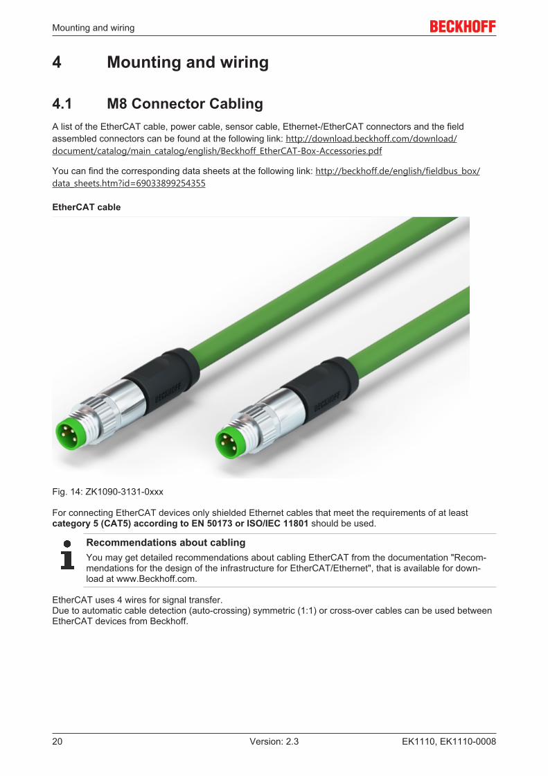
4.1 M8 Connector CablingA list of the EtherCAT cable, power cable, sensor cable, Ethernet-/EtherCAT connectors and the fieldassembled connectors can be found at the following link: http://download.beckhoff.com/download/document/catalog/main_catalog/english/Beckhoff_EtherCAT-Box-Accessories.pdf
You can find the corresponding data sheets at the following link: http://beckhoff.de/english/fieldbus_box/data_sheets.htm?id=69033899254355
EtherCAT cable
Fig. 14: ZK1090-3131-0xxx
For connecting EtherCAT devices only shielded Ethernet cables that meet the requirements of at leastcategory 5 (CAT5) according to EN 50173 or ISO/IEC 11801 should be used.
Recommendations about cablingYou may get detailed recommendations about cabling EtherCAT from the documentation "Recom-mendations for the design of the infrastructure for EtherCAT/Ethernet", that is available for down-load at www.Beckhoff.com.
EtherCAT uses 4 wires for signal transfer.Due to automatic cable detection (auto-crossing) symmetric (1:1) or cross-over cables can be used betweenEtherCAT devices from Beckhoff.
Mounting and wiring
EK1110, EK1110-0008 21Version: 2.3
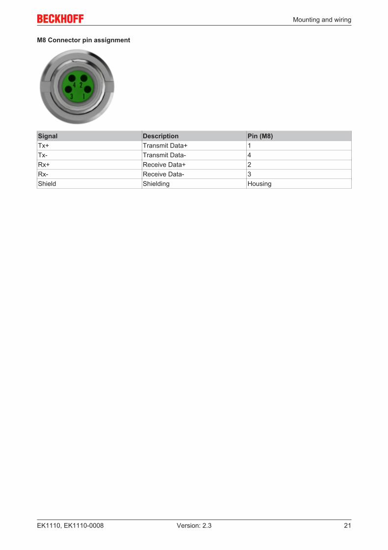
M8 Connector pin assignment
Signal Description Pin (M8)Tx+ Transmit Data+ 1Tx- Transmit Data- 4Rx+ Receive Data+ 2Rx- Receive Data- 3Shield Shielding Housing
Mounting and wiring
EK1110, EK1110-000822 Version: 2.3
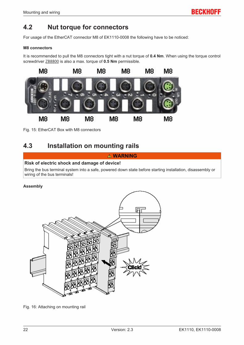
4.2 Nut torque for connectorsFor usage of the EtherCAT connector M8 of EK1110-0008 the following have to be noticed:
M8 connectors
It is recommended to pull the M8 connectors tight with a nut torque of 0.4 Nm. When using the torque controlscrewdriver ZB8800 is also a max. torque of 0.5 Nm permissible.
Fig. 15: EtherCAT Box with M8 connectors
4.3 Installation on mounting rails WARNING
Risk of electric shock and damage of device!Bring the bus terminal system into a safe, powered down state before starting installation, disassembly orwiring of the bus terminals!
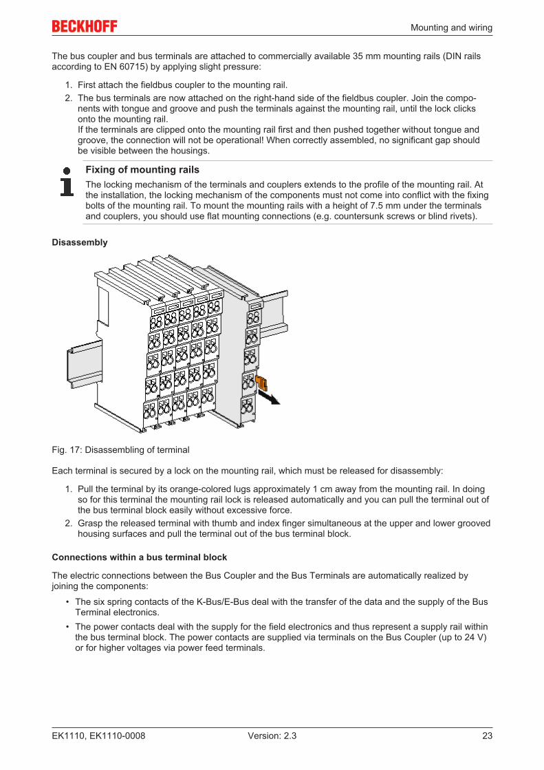
Assembly
Fig. 16: Attaching on mounting rail
Mounting and wiring
EK1110, EK1110-0008 23Version: 2.3
The bus coupler and bus terminals are attached to commercially available 35 mm mounting rails (DIN railsaccording to EN 60715) by applying slight pressure:
1. First attach the fieldbus coupler to the mounting rail.2. The bus terminals are now attached on the right-hand side of the fieldbus coupler. Join the compo-
nents with tongue and groove and push the terminals against the mounting rail, until the lock clicksonto the mounting rail.If the terminals are clipped onto the mounting rail first and then pushed together without tongue andgroove, the connection will not be operational! When correctly assembled, no significant gap shouldbe visible between the housings.
Fixing of mounting railsThe locking mechanism of the terminals and couplers extends to the profile of the mounting rail. Atthe installation, the locking mechanism of the components must not come into conflict with the fixingbolts of the mounting rail. To mount the mounting rails with a height of 7.5 mm under the terminalsand couplers, you should use flat mounting connections (e.g. countersunk screws or blind rivets).
Disassembly
Fig. 17: Disassembling of terminal
Each terminal is secured by a lock on the mounting rail, which must be released for disassembly:
1. Pull the terminal by its orange-colored lugs approximately 1 cm away from the mounting rail. In doingso for this terminal the mounting rail lock is released automatically and you can pull the terminal out ofthe bus terminal block easily without excessive force.
2. Grasp the released terminal with thumb and index finger simultaneous at the upper and lower groovedhousing surfaces and pull the terminal out of the bus terminal block.
Connections within a bus terminal block
The electric connections between the Bus Coupler and the Bus Terminals are automatically realized byjoining the components:
• The six spring contacts of the K-Bus/E-Bus deal with the transfer of the data and the supply of the BusTerminal electronics.
• The power contacts deal with the supply for the field electronics and thus represent a supply rail withinthe bus terminal block. The power contacts are supplied via terminals on the Bus Coupler (up to 24 V)or for higher voltages via power feed terminals.
Mounting and wiring
EK1110, EK1110-000824 Version: 2.3
Power ContactsDuring the design of a bus terminal block, the pin assignment of the individual Bus Terminals mustbe taken account of, since some types (e.g. analog Bus Terminals or digital 4-channel Bus Termi-nals) do not or not fully loop through the power contacts. Power Feed Terminals (KL91xx, KL92xxor EL91xx, EL92xx) interrupt the power contacts and thus represent the start of a new supply rail.
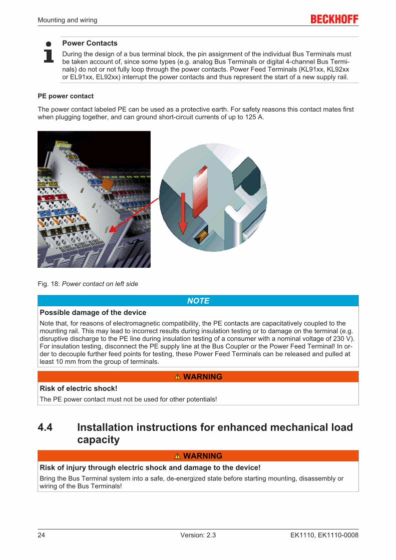
PE power contact
The power contact labeled PE can be used as a protective earth. For safety reasons this contact mates firstwhen plugging together, and can ground short-circuit currents of up to 125 A.
Fig. 18: Power contact on left side
NOTEPossible damage of the deviceNote that, for reasons of electromagnetic compatibility, the PE contacts are capacitatively coupled to themounting rail. This may lead to incorrect results during insulation testing or to damage on the terminal (e.g.disruptive discharge to the PE line during insulation testing of a consumer with a nominal voltage of 230 V).For insulation testing, disconnect the PE supply line at the Bus Coupler or the Power Feed Terminal! In or-der to decouple further feed points for testing, these Power Feed Terminals can be released and pulled atleast 10 mm from the group of terminals.
WARNINGRisk of electric shock!The PE power contact must not be used for other potentials!
4.4 Installation instructions for enhanced mechanical loadcapacity
WARNINGRisk of injury through electric shock and damage to the device!Bring the Bus Terminal system into a safe, de-energized state before starting mounting, disassembly orwiring of the Bus Terminals!
Mounting and wiring
EK1110, EK1110-0008 25Version: 2.3
Additional checks
The terminals have undergone the following additional tests:
Verification ExplanationVibration 10 frequency runs in 3 axes
6 Hz < f < 60 Hz displacement 0.35 mm, constant amplitude60.1 Hz < f < 500 Hz acceleration 5 g, constant amplitude
Shocks 1000 shocks in each direction, in 3 axes25 g, 6 ms
Additional installation instructions
For terminals with enhanced mechanical load capacity, the following additional installation instructions apply:
• The enhanced mechanical load capacity is valid for all permissible installation positions• Use a mounting rail according to EN 60715 TH35-15• Fix the terminal segment on both sides of the mounting rail with a mechanical fixture, e.g. an earth
terminal or reinforced end clamp• The maximum total extension of the terminal segment (without coupler) is:
64 terminals (12 mm mounting with) or 32 terminals (24 mm mounting with)• Avoid deformation, twisting, crushing and bending of the mounting rail during edging and installation of
the rail• The mounting points of the mounting rail must be set at 5 cm intervals• Use countersunk head screws to fasten the mounting rail• The free length between the strain relief and the wire connection should be kept as short as possible. A
distance of approx. 10 cm should be maintained to the cable duct.
4.5 Installation positionsNOTE
Constraints regarding installation position and operating temperature rangePlease refer to the technical data for a terminal to ascertain whether any restrictions regarding the installa-tion position and/or the operating temperature range have been specified. When installing high power dissi-pation terminals ensure that an adequate spacing is maintained between other components above and be-low the terminal in order to guarantee adequate ventilation!
Optimum installation position (standard)
The optimum installation position requires the mounting rail to be installed horizontally and the connectionsurfaces of the EL/KL terminals to face forward (see Fig. “Recommended distances for standard installationposition”). The terminals are ventilated from below, which enables optimum cooling of the electronics throughconvection. "From below" is relative to the acceleration of gravity.

Mounting and wiring
EK1110, EK1110-000826 Version: 2.3
Fig. 19: Recommended distances for standard installation position
Compliance with the distances shown in Fig. “Recommended distances for standard installation position” isrecommended.
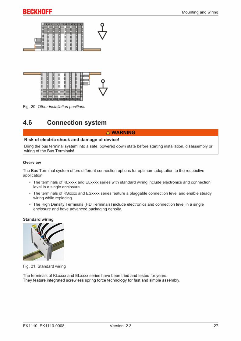
Other installation positions
All other installation positions are characterized by different spatial arrangement of the mounting rail - seeFig “Other installation positions”.
The minimum distances to ambient specified above also apply to these installation positions.
Mounting and wiring
EK1110, EK1110-0008 27Version: 2.3
Fig. 20: Other installation positions
4.6 Connection system WARNING
Risk of electric shock and damage of device!Bring the bus terminal system into a safe, powered down state before starting installation, disassembly orwiring of the Bus Terminals!
Overview
The Bus Terminal system offers different connection options for optimum adaptation to the respectiveapplication:
• The terminals of KLxxxx and ELxxxx series with standard wiring include electronics and connectionlevel in a single enclosure.
• The terminals of KSxxxx and ESxxxx series feature a pluggable connection level and enable steadywiring while replacing.
• The High Density Terminals (HD Terminals) include electronics and connection level in a singleenclosure and have advanced packaging density.
Standard wiring
Fig. 21: Standard wiring
The terminals of KLxxxx and ELxxxx series have been tried and tested for years.They feature integrated screwless spring force technology for fast and simple assembly.

Mounting and wiring
EK1110, EK1110-000828 Version: 2.3
Pluggable wiring
Fig. 22: Pluggable wiring
The terminals of KSxxxx and ESxxxx series feature a pluggable connection level.The assembly and wiring procedure for the KS series is the same as for the KLxxxx and ELxxxx series.The KS/ES series terminals enable the complete wiring to be removed as a plug connector from the top ofthe housing for servicing.The lower section can be removed from the terminal block by pulling the unlocking tab. Insert the new component and plug in the connector with the wiring. This reduces the installation time andeliminates the risk of wires being mixed up.
The familiar dimensions of the terminal only had to be changed slightly. The new connector adds about 3mm. The maximum height of the terminal remains unchanged.
A tab for strain relief of the cable simplifies assembly in many applications and prevents tangling of individualconnection wires when the connector is removed.
Conductor cross sections between 0.08 mm2 and 2.5 mm2 can continue to be used with the proven springforce technology.
The overview and nomenclature of the product names for KSxxxx and ESxxxx series has been retained asknown from KLxxxx and ELxxxx series.
High Density Terminals (HD Terminals)
Fig. 23: High Density Terminals
The Bus Terminals from these series with 16 connection points are distinguished by a particularly compactdesign, as the packaging density is twice as large as that of the standard 12 mm Bus Terminals. Massiveconductors and conductors with a wire end sleeve can be inserted directly into the spring loaded terminalpoint without tools.
Wiring HD TerminalsThe High Density (HD) Terminals of the KLx8xx and ELx8xx series doesn't support steady wiring.
Ultrasonically "bonded" (ultrasonically welded) conductors
Ultrasonically “bonded" conductorsIt is also possible to connect the Standard and High Density Terminals with ultrasonically"bonded" (ultrasonically welded) conductors. In this case, please note the tables concerning thewire-size width [} 29] below!

Mounting and wiring
EK1110, EK1110-0008 29Version: 2.3
Wiring
Terminals for standard wiring ELxxxx/KLxxxx and for pluggable wiring ESxxxx/KSxxxx
Fig. 24: Mounting a cable on a terminal connection
Up to eight connections enable the connection of solid or finely stranded cables to the Bus Terminals. Theterminals are implemented in spring force technology. Connect the cables as follows:
1. Open a spring-loaded terminal by slightly pushing with a screwdriver or a rod into the square openingabove the terminal.
2. The wire can now be inserted into the round terminal opening without any force.3. The terminal closes automatically when the pressure is released, holding the wire securely and per-
manently.
Terminal housing ELxxxx, KLxxxx ESxxxx, KSxxxxWire size width 0.08 ... 2,5 mm2 0.08 ... 2.5 mm2
Wire stripping length 8 ... 9 mm 9 ... 10 mm
High Density Terminals ELx8xx, KLx8xx (HD)
The conductors of the HD Terminals are connected without tools for single-wire conductors using the directplug-in technique, i.e. after stripping the wire is simply plugged into the contact point. The cables arereleased, as usual, using the contact release with the aid of a screwdriver. See the following table for thesuitable wire size width.
Terminal housing High Density HousingWire size width (conductors with a wire end sleeve) 0.14 ... 0.75 mm2
Wire size width (single core wires) 0.08 ... 1.5 mm2
Wire size width (fine-wire conductors) 0.25 ... 1.5 mm2
Wire size width (ultrasonically “bonded" conductors) only 1.5 mm2 (see notice [} 28]!)Wire stripping length 8 ... 9 mm
Mounting and wiring
EK1110, EK1110-000830 Version: 2.3
Shielding
ShieldingAnalog sensors and actors should always be connected with shielded, twisted paired wires.
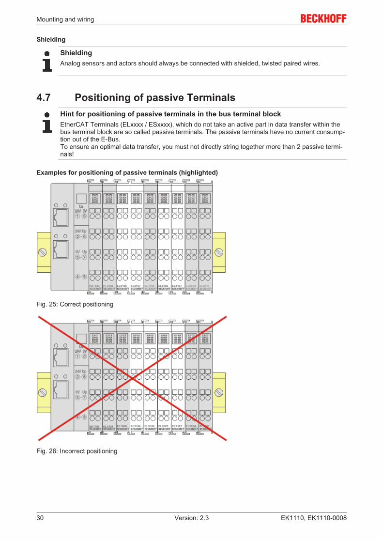
4.7 Positioning of passive TerminalsHint for positioning of passive terminals in the bus terminal blockEtherCAT Terminals (ELxxxx / ESxxxx), which do not take an active part in data transfer within thebus terminal block are so called passive terminals. The passive terminals have no current consump-tion out of the E-Bus. To ensure an optimal data transfer, you must not directly string together more than 2 passive termi-nals!
Examples for positioning of passive terminals (highlighted)
Fig. 25: Correct positioning
Fig. 26: Incorrect positioning

Mounting and wiring
EK1110, EK1110-0008 31Version: 2.3
4.8 ATEX - Special conditions (standard temperaturerange)
WARNINGObserve the special conditions for the intended use of Beckhoff fieldbus components withstandard temperature range in potentially explosive areas (directive 94/9/EU)!• The certified components are to be installed in a suitable housing that guarantees a protection class of at
least IP54 in accordance with EN 60529! The environmental conditions during use are thereby to betaken into account!
• If the temperatures during rated operation are higher than 70°C at the feed-in points of cables, lines orpipes, or higher than 80°C at the wire branching points, then cables must be selected whose tempera-ture data correspond to the actual measured temperature values!
• Observe the permissible ambient temperature range of 0 to 55°C for the use of Beckhoff fieldbus compo-nents standard temperature range in potentially explosive areas!
• Measures must be taken to protect against the rated operating voltage being exceeded by more than40% due to short-term interference voltages!
• The individual terminals may only be unplugged or removed from the Bus Terminal system if the supplyvoltage has been switched off or if a non-explosive atmosphere is ensured!
• The connections of the certified components may only be connected or disconnected if the supply volt-age has been switched off or if a non-explosive atmosphere is ensured!
• The fuses of the KL92xx/EL92xx power feed terminals may only be exchanged if the supply voltage hasbeen switched off or if a non-explosive atmosphere is ensured!
• Address selectors and ID switches may only be adjusted if the supply voltage has been switched off or ifa non-explosive atmosphere is ensured!
Standards
The fundamental health and safety requirements are fulfilled by compliance with the following standards:
• EN 60079-0:2012+A11:2013• EN 60079-15:2010
Marking
The Beckhoff fieldbus components with standard temperature range certified for potentially explosive areasbear one of the following markings:
II 3G KEMA 10ATEX0075 X Ex nA IIC T4 Gc Ta: 0 … 55°C
or
II 3G KEMA 10ATEX0075 X Ex nC IIC T4 Gc Ta: 0 … 55°C

Mounting and wiring
EK1110, EK1110-000832 Version: 2.3
4.9 ATEX - Special conditions (extended temperaturerange)
WARNINGObserve the special conditions for the intended use of Beckhoff fieldbus components withextended temperature range (ET) in potentially explosive areas (directive 94/9/EU)!• The certified components are to be installed in a suitable housing that guarantees a protection class of at
least IP54 in accordance with EN 60529! The environmental conditions during use are thereby to betaken into account!
• If the temperatures during rated operation are higher than 70°C at the feed-in points of cables, lines orpipes, or higher than 80°C at the wire branching points, then cables must be selected whose tempera-ture data correspond to the actual measured temperature values!
• Observe the permissible ambient temperature range of -25 to 60°C for the use of Beckhoff fieldbus com-ponents with extended temperature range (ET) in potentially explosive areas!
• Measures must be taken to protect against the rated operating voltage being exceeded by more than40% due to short-term interference voltages!
• The individual terminals may only be unplugged or removed from the Bus Terminal system if the supplyvoltage has been switched off or if a non-explosive atmosphere is ensured!
• The connections of the certified components may only be connected or disconnected if the supply volt-age has been switched off or if a non-explosive atmosphere is ensured!
• The fuses of the KL92xx/EL92xx power feed terminals may only be exchanged if the supply voltage hasbeen switched off or if a non-explosive atmosphere is ensured!
• Address selectors and ID switches may only be adjusted if the supply voltage has been switched off or ifa non-explosive atmosphere is ensured!
Standards
The fundamental health and safety requirements are fulfilled by compliance with the following standards:
• EN 60079-0:2012+A11:2013• EN 60079-15:2010
Marking
The Beckhoff fieldbus components with extended temperature range (ET) certified for potentially explosiveareas bear the following marking:
II 3G KEMA 10ATEX0075 X Ex nA IIC T4 Gc Ta: -25 … 60°C
or
II 3G KEMA 10ATEX0075 X Ex nC IIC T4 Gc Ta: -25 … 60°C
Mounting and wiring
EK1110, EK1110-0008 33Version: 2.3
4.10 ATEX DocumentationNotes about operation of the Beckhoff terminal systems in potentially explosive ar-eas (ATEX)Pay also attention to the continuative documentation
Notes about operation of the Beckhoff terminal systems in potentially explosive areas (ATEX)
that is available in the download area of the Beckhoff homepage http:\\www.beckhoff.com!
4.11 UL noticeApplicationBeckhoff EtherCAT modules are intended for use with Beckhoff’s UL Listed EtherCAT Sys-tem only.
ExaminationFor cULus examination, the Beckhoff I/O System has only been investigated for risk of fireand electrical shock (in accordance with UL508 and CSA C22.2 No. 142).
For devices with Ethernet connectorsNot for connection to telecommunication circuits.
Basic principles
Two UL certificates are met in the Beckhoff EtherCAT product range, depending upon the components:
1. UL certification according to UL508. Devices with this kind of certification are marked by this sign:
2. UL certification according to UL508 with limited power consumption. The current consumed by the de-vice is limited to a max. possible current consumption of 4 A. Devices with this kind of certification aremarked by this sign:
Almost all current EtherCAT products (as at 2010/05) are UL certified without restrictions.
Application
If terminals certified with restrictions are used, then the current consumption at 24 VDC must be limitedaccordingly by means of supply
• from an isolated source protected by a fuse of max. 4 A (according to UL248) or• from a voltage supply complying with NEC class 2.
A voltage source complying with NEC class 2 may not be connected in series or parallel with anotherNEC class 2compliant voltage supply!
Mounting and wiring
EK1110, EK1110-000834 Version: 2.3
These requirements apply to the supply of all EtherCAT bus couplers, power adaptor terminals, BusTerminals and their power contacts.
Commissioning
EK1110, EK1110-0008 35Version: 2.3
5 Commissioning
5.1 EK1110 - Configuration by means of the TwinCATSystem Manager
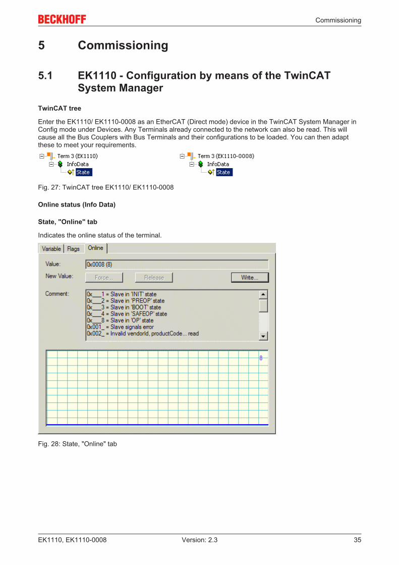
TwinCAT tree
Enter the EK1110/ EK1110-0008 as an EtherCAT (Direct mode) device in the TwinCAT System Manager inConfig mode under Devices. Any Terminals already connected to the network can also be read. This willcause all the Bus Couplers with Bus Terminals and their configurations to be loaded. You can then adaptthese to meet your requirements.
Fig. 27: TwinCAT tree EK1110/ EK1110-0008
Online status (Info Data)
State, "Online" tab
Indicates the online status of the terminal.
Fig. 28: State, "Online" tab

Commissioning
EK1110, EK1110-000836 Version: 2.3
Value Description0x___1 Slave in 'INIT' state0x___2 Slave in 'PREOP' state0x___3 Slave in 'BOOT' state0x___4 Slave in 'SAFEOP' state0x___8 Slave in 'OP' state0x001_ Slave signals error0x002_ Invalid vendorId, productCode... read0x004_ Initialization error occurred0x010_ Slave not present0x020_ Slave signals link error0x040_ Slave signals missing link0x080_ Slave signals unexpected link0x100_ Communication port A0x200_ Communication port B0x400_ Communication port C0x800_ Communication port D

Error handling and diagnostics
EK1110, EK1110-0008 37Version: 2.3
6 Error handling and diagnostics
6.1 Diagnostic LED
Fig. 29: EK1110/ EK1110-0008
LEDs for fieldbus diagnostics
LED Display State DescriptionLINK / ACT(X1)
green
off - no connection on the EtherCAT strandon linked EtherCAT device connectedflashing active Communication with EtherCAT device
LED diagnostics EtherCAT State Machine
LED Color MeaningRUN green This LED indicates the terminal's operating state:
off State of the EtherCAT State Machine: INIT = initialization of the terminalflashing uniformly State of the EtherCAT State Machine: PREOP = function for mailbox
communication and different standard-settings setflashing slowly State of the EtherCAT State Machine: SAFEOP = verification of the
sync manager channels and the distributed clocks.Outputs remain in safe state
on State of the EtherCAT State Machine: OP = normal operating state;mailbox and process data communication is possible
flashing rapidly State of the EtherCAT State Machine: BOOTSTRAP = function forterminal firmware updates
Appendix
EK1110, EK1110-000838 Version: 2.3
7 Appendix
7.1 EtherCAT AL Status CodesFor detailed information please refer to the EtherCAT system description.
7.2 Firmware compatibilityThe EK1110 has no firmware.
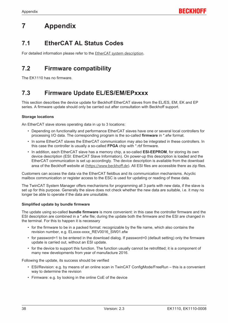
7.3 Firmware Update EL/ES/EM/EPxxxxThis section describes the device update for Beckhoff EtherCAT slaves from the EL/ES, EM, EK and EPseries. A firmware update should only be carried out after consultation with Beckhoff support.
Storage locations
An EtherCAT slave stores operating data in up to 3 locations:
• Depending on functionality and performance EtherCAT slaves have one or several local controllers forprocessing I/O data. The corresponding program is the so-called firmware in *.efw format.
• In some EtherCAT slaves the EtherCAT communication may also be integrated in these controllers. Inthis case the controller is usually a so-called FPGA chip with *.rbf firmware.
• In addition, each EtherCAT slave has a memory chip, a so-called ESI-EEPROM, for storing its owndevice description (ESI: EtherCAT Slave Information). On power-up this description is loaded and theEtherCAT communication is set up accordingly. The device description is available from the downloadarea of the Beckhoff website at (https://www.beckhoff.de). All ESI files are accessible there as zip files.
Customers can access the data via the EtherCAT fieldbus and its communication mechanisms. Acyclicmailbox communication or register access to the ESC is used for updating or reading of these data.
The TwinCAT System Manager offers mechanisms for programming all 3 parts with new data, if the slave isset up for this purpose. Generally the slave does not check whether the new data are suitable, i.e. it may nolonger be able to operate if the data are unsuitable.
Simplified update by bundle firmware
The update using so-called bundle firmware is more convenient: in this case the controller firmware and theESI description are combined in a *.efw file; during the update both the firmware and the ESI are changed inthe terminal. For this to happen it is necessary
• for the firmware to be in a packed format: recognizable by the file name, which also contains therevision number, e.g. ELxxxx-xxxx_REV0016_SW01.efw
• for password=1 to be entered in the download dialog. If password=0 (default setting) only the firmwareupdate is carried out, without an ESI update.
• for the device to support this function. The function usually cannot be retrofitted; it is a component ofmany new developments from year of manufacture 2016.
Following the update, its success should be verified
• ESI/Revision: e.g. by means of an online scan in TwinCAT ConfigMode/FreeRun – this is a convenientway to determine the revision
• Firmware: e.g. by looking in the online CoE of the device
Appendix
EK1110, EK1110-0008 39Version: 2.3
NOTERisk of damage to the device!Note the following when downloading new device files
• Firmware downloads to an EtherCAT device must not be interrupted• Flawless EtherCAT communication must be ensured. CRC errors or LostFrames must be avoided.• The power supply must adequately dimensioned. The signal level must meet the specification.
In the event of malfunctions during the update process the EtherCAT device may become unusable and re-quire re-commissioning by the manufacturer.
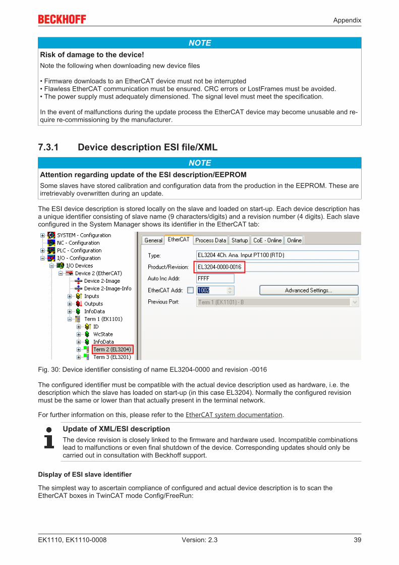
7.3.1 Device description ESI file/XMLNOTE
Attention regarding update of the ESI description/EEPROMSome slaves have stored calibration and configuration data from the production in the EEPROM. These areirretrievably overwritten during an update.
The ESI device description is stored locally on the slave and loaded on start-up. Each device description hasa unique identifier consisting of slave name (9 characters/digits) and a revision number (4 digits). Each slaveconfigured in the System Manager shows its identifier in the EtherCAT tab:
Fig. 30: Device identifier consisting of name EL3204-0000 and revision -0016
The configured identifier must be compatible with the actual device description used as hardware, i.e. thedescription which the slave has loaded on start-up (in this case EL3204). Normally the configured revisionmust be the same or lower than that actually present in the terminal network.
For further information on this, please refer to the EtherCAT system documentation.
Update of XML/ESI descriptionThe device revision is closely linked to the firmware and hardware used. Incompatible combinationslead to malfunctions or even final shutdown of the device. Corresponding updates should only becarried out in consultation with Beckhoff support.
Display of ESI slave identifier
The simplest way to ascertain compliance of configured and actual device description is to scan theEtherCAT boxes in TwinCAT mode Config/FreeRun:
Appendix
EK1110, EK1110-000840 Version: 2.3
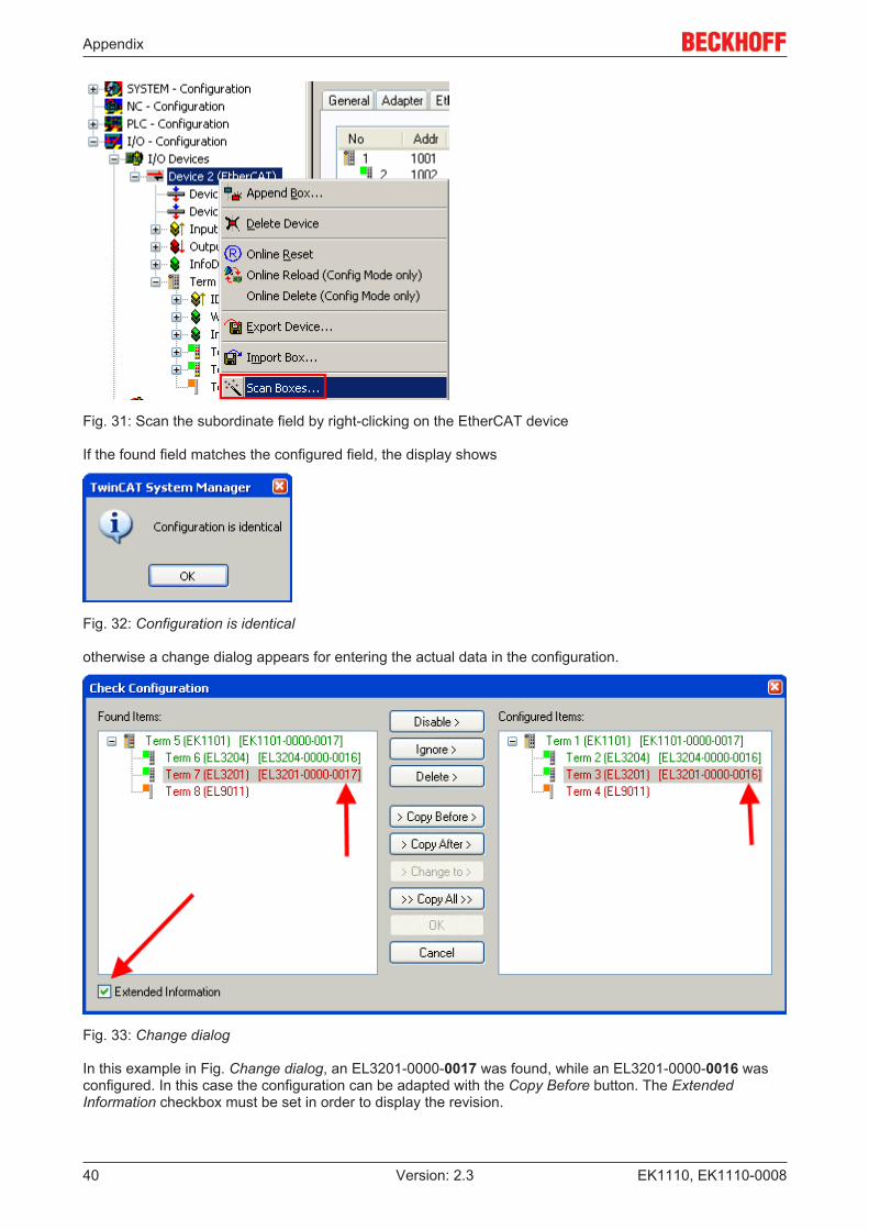
Fig. 31: Scan the subordinate field by right-clicking on the EtherCAT device
If the found field matches the configured field, the display shows
Fig. 32: Configuration is identical
otherwise a change dialog appears for entering the actual data in the configuration.
Fig. 33: Change dialog
In this example in Fig. Change dialog, an EL3201-0000-0017 was found, while an EL3201-0000-0016 wasconfigured. In this case the configuration can be adapted with the Copy Before button. The ExtendedInformation checkbox must be set in order to display the revision.
Appendix
EK1110, EK1110-0008 41Version: 2.3
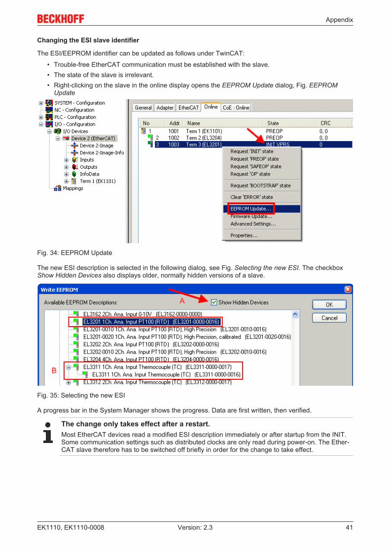
Changing the ESI slave identifier
The ESI/EEPROM identifier can be updated as follows under TwinCAT:
• Trouble-free EtherCAT communication must be established with the slave.• The state of the slave is irrelevant.• Right-clicking on the slave in the online display opens the EEPROM Update dialog, Fig. EEPROM
Update
Fig. 34: EEPROM Update
The new ESI description is selected in the following dialog, see Fig. Selecting the new ESI. The checkboxShow Hidden Devices also displays older, normally hidden versions of a slave.
Fig. 35: Selecting the new ESI
A progress bar in the System Manager shows the progress. Data are first written, then verified.
The change only takes effect after a restart.Most EtherCAT devices read a modified ESI description immediately or after startup from the INIT.Some communication settings such as distributed clocks are only read during power-on. The Ether-CAT slave therefore has to be switched off briefly in order for the change to take effect.

Appendix
EK1110, EK1110-000842 Version: 2.3
7.3.2 Firmware explanation
Determining the firmware version
Determining the version on laser inscription
Beckhoff EtherCAT slaves feature serial numbers applied by laser. The serial number has the followingstructure: KK YY FF HH
KK - week of production (CW, calendar week)YY - year of productionFF - firmware versionHH - hardware version
Example with ser. no.: 12 10 03 02:
12 - week of production 1210 - year of production 201003 - firmware version 0302 - hardware version 02
Determining the version via the System Manager
The TwinCAT System Manager shows the version of the controller firmware if the master can access theslave online. Click on the E-Bus Terminal whose controller firmware you want to check (in the exampleterminal 2 (EL3204)) and select the tab CoE Online (CAN over EtherCAT).
CoE Online and Offline CoETwo CoE directories are available: • online: This is offered in the EtherCAT slave by the controller, if the EtherCAT slave supports this.This CoE directory can only be displayed if a slave is connected and operational.• offline: The EtherCAT Slave Information ESI/XML may contain the default content of the CoE.This CoE directory can only be displayed if it is included in the ESI (e.g. "Beckhoff EL5xxx.xml").The Advanced button must be used for switching between the two views.
In Fig. Display of EL3204 firmware version the firmware version of the selected EL3204 is shown as 03 inCoE entry 0x100A.
Fig. 36: Display of EL3204 firmware version
In (A) TwinCAT 2.11 shows that the Online CoE directory is currently displayed. If this is not the case, theOnline directory can be loaded via the Online option in Advanced Settings (B) and double-clicking onAllObjects.
Appendix
EK1110, EK1110-0008 43Version: 2.3
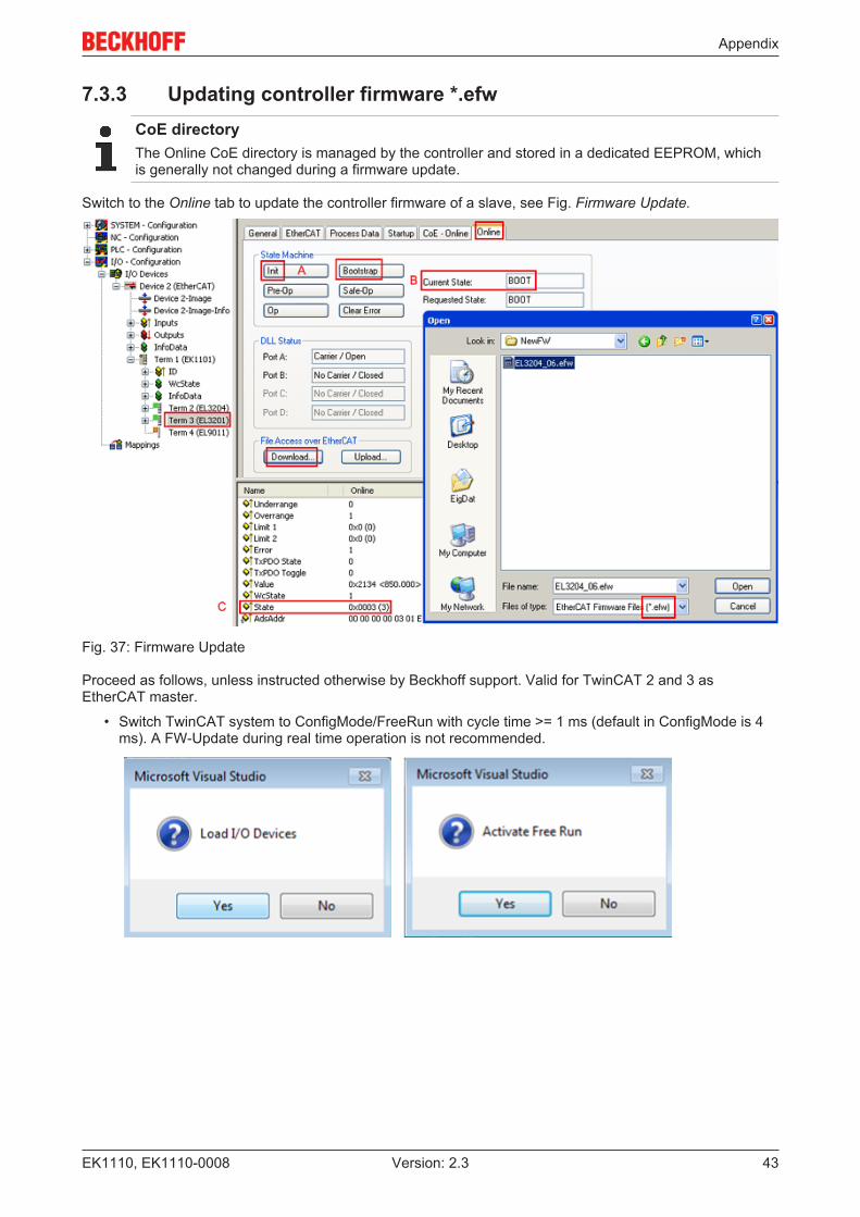
7.3.3 Updating controller firmware *.efwCoE directoryThe Online CoE directory is managed by the controller and stored in a dedicated EEPROM, whichis generally not changed during a firmware update.
Switch to the Online tab to update the controller firmware of a slave, see Fig. Firmware Update.
Fig. 37: Firmware Update
Proceed as follows, unless instructed otherwise by Beckhoff support. Valid for TwinCAT 2 and 3 asEtherCAT master.
• Switch TwinCAT system to ConfigMode/FreeRun with cycle time >= 1 ms (default in ConfigMode is 4ms). A FW-Update during real time operation is not recommended.
Appendix
EK1110, EK1110-000844 Version: 2.3
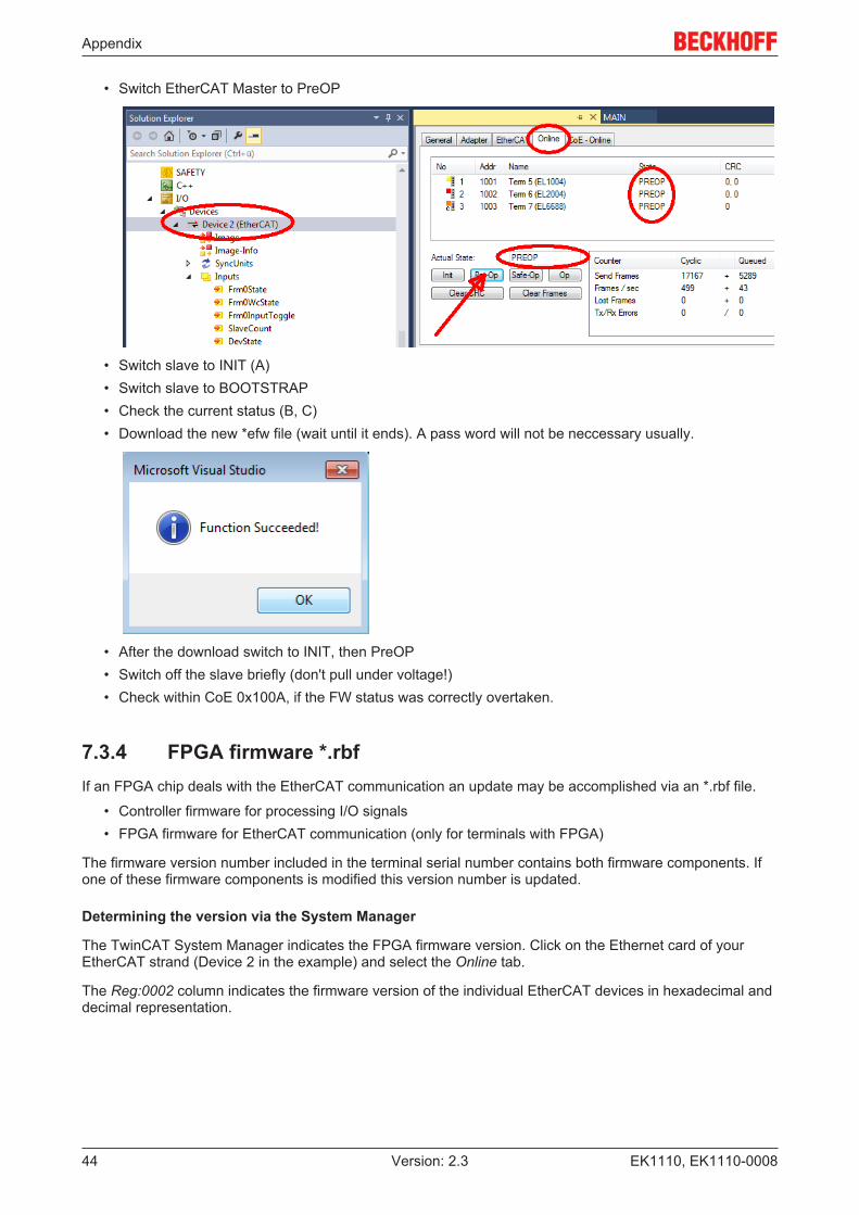
• Switch EtherCAT Master to PreOP
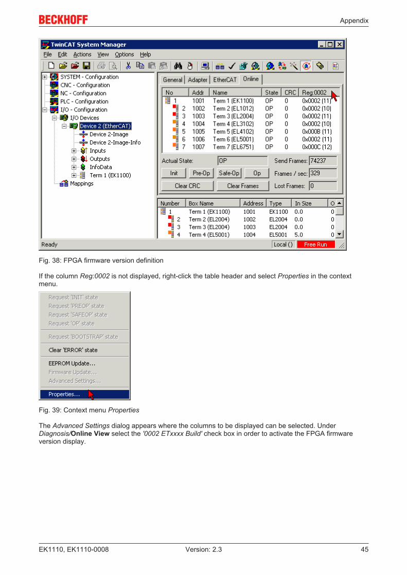
• Switch slave to INIT (A)• Switch slave to BOOTSTRAP• Check the current status (B, C)• Download the new *efw file (wait until it ends). A pass word will not be neccessary usually.
• After the download switch to INIT, then PreOP• Switch off the slave briefly (don't pull under voltage!)• Check within CoE 0x100A, if the FW status was correctly overtaken.
7.3.4 FPGA firmware *.rbfIf an FPGA chip deals with the EtherCAT communication an update may be accomplished via an *.rbf file.
• Controller firmware for processing I/O signals• FPGA firmware for EtherCAT communication (only for terminals with FPGA)
The firmware version number included in the terminal serial number contains both firmware components. Ifone of these firmware components is modified this version number is updated.
Determining the version via the System Manager
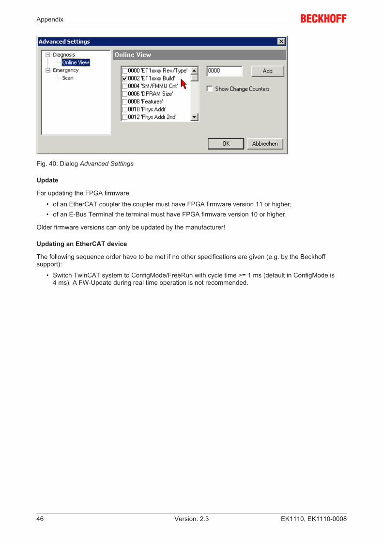
The TwinCAT System Manager indicates the FPGA firmware version. Click on the Ethernet card of yourEtherCAT strand (Device 2 in the example) and select the Online tab.
The Reg:0002 column indicates the firmware version of the individual EtherCAT devices in hexadecimal anddecimal representation.
Appendix
EK1110, EK1110-0008 45Version: 2.3
Fig. 38: FPGA firmware version definition
If the column Reg:0002 is not displayed, right-click the table header and select Properties in the contextmenu.
Fig. 39: Context menu Properties
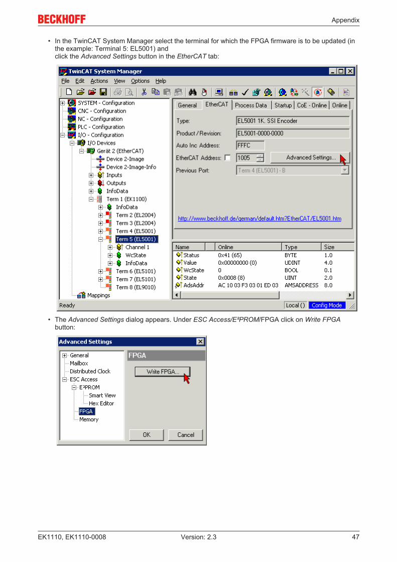
The Advanced Settings dialog appears where the columns to be displayed can be selected. UnderDiagnosis/Online View select the '0002 ETxxxx Build' check box in order to activate the FPGA firmwareversion display.
Appendix
EK1110, EK1110-000846 Version: 2.3
Fig. 40: Dialog Advanced Settings
Update
For updating the FPGA firmware
• of an EtherCAT coupler the coupler must have FPGA firmware version 11 or higher;• of an E-Bus Terminal the terminal must have FPGA firmware version 10 or higher.
Older firmware versions can only be updated by the manufacturer!
Updating an EtherCAT device
The following sequence order have to be met if no other specifications are given (e.g. by the Beckhoffsupport):
• Switch TwinCAT system to ConfigMode/FreeRun with cycle time >= 1 ms (default in ConfigMode is4 ms). A FW-Update during real time operation is not recommended.
Appendix
EK1110, EK1110-0008 47Version: 2.3
• In the TwinCAT System Manager select the terminal for which the FPGA firmware is to be updated (inthe example: Terminal 5: EL5001) and click the Advanced Settings button in the EtherCAT tab:
• The Advanced Settings dialog appears. Under ESC Access/E²PROM/FPGA click on Write FPGAbutton:
Appendix
EK1110, EK1110-000848 Version: 2.3
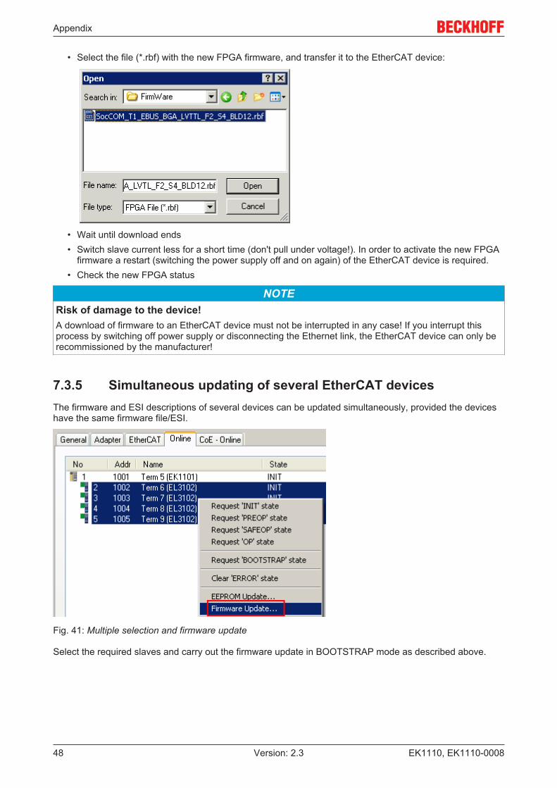
• Select the file (*.rbf) with the new FPGA firmware, and transfer it to the EtherCAT device:
• Wait until download ends• Switch slave current less for a short time (don't pull under voltage!). In order to activate the new FPGA
firmware a restart (switching the power supply off and on again) of the EtherCAT device is required.• Check the new FPGA status
NOTERisk of damage to the device!A download of firmware to an EtherCAT device must not be interrupted in any case! If you interrupt thisprocess by switching off power supply or disconnecting the Ethernet link, the EtherCAT device can only berecommissioned by the manufacturer!
7.3.5 Simultaneous updating of several EtherCAT devicesThe firmware and ESI descriptions of several devices can be updated simultaneously, provided the deviceshave the same firmware file/ESI.
Fig. 41: Multiple selection and firmware update
Select the required slaves and carry out the firmware update in BOOTSTRAP mode as described above.

Appendix
EK1110, EK1110-0008 49Version: 2.3
7.4 Support and ServiceBeckhoff and their partners around the world offer comprehensive support and service, making available fastand competent assistance with all questions related to Beckhoff products and system solutions.
Beckhoff's branch offices and representatives
Please contact your Beckhoff branch office or representative for local support and service on Beckhoffproducts!
The addresses of Beckhoff's branch offices and representatives round the world can be found on her internetpages:http://www.beckhoff.com
You will also find further documentation for Beckhoff components there.
Beckhoff Headquarters
Beckhoff Automation GmbH & Co. KG
Huelshorstweg 2033415 VerlGermany
Phone: +49(0)5246/963-0Fax: +49(0)5246/963-198e-mail: [email protected]
Beckhoff Support
Support offers you comprehensive technical assistance, helping you not only with the application ofindividual Beckhoff products, but also with other, wide-ranging services:
• support• design, programming and commissioning of complex automation systems• and extensive training program for Beckhoff system components
Hotline: +49(0)5246/963-157Fax: +49(0)5246/963-9157e-mail: [email protected]
Beckhoff Service
The Beckhoff Service Center supports you in all matters of after-sales service:
• on-site service• repair service• spare parts service• hotline service
Hotline: +49(0)5246/963-460Fax: +49(0)5246/963-479e-mail: [email protected]
List of illustrations
EK1110, EK1110-000850 Version: 2.3
List of illustrationsFig. 1 EL5021 EL terminal, standard IP20 IO device with serial/ batch number and revision ID (since
2014/01)....................................................................................................................................... 9Fig. 2 EK1100 EtherCAT coupler, standard IP20 IO device with serial/ batch number......................... 9Fig. 3 CU2016 switch with serial/ batch number.................................................................................... 9Fig. 4 EL3202-0020 with serial/ batch number 26131006 and unique ID-number 204418 ................... 10Fig. 5 EP1258-00001 IP67 EtherCAT Box with batch number/ date code 22090101 and unique se-
rial number 158102...................................................................................................................... 10Fig. 6 EP1908-0002 IP67 EtherCAT Safety Box with batch number/ date code 071201FF and
unique serial number 00346070 .................................................................................................. 10Fig. 7 EL2904 IP20 safety terminal with batch number/ date code 50110302 and unique serial num-
ber 00331701............................................................................................................................... 10Fig. 8 ELM3604-0002 terminal with unique ID number (QR code) 100001051 and serial/ batch num-
ber 44160201............................................................................................................................... 11Fig. 9 EK1110/ EK1110-0008 ................................................................................................................ 12Fig. 10 EtherCAT Telegram Structure ..................................................................................................... 14Fig. 11 EtherCAT Topology ..................................................................................................................... 15Fig. 12 System manager current calculation .......................................................................................... 17Fig. 13 States of the EtherCAT State Machine........................................................................................ 18Fig. 14 ZK1090-3131-0xxx ...................................................................................................................... 20Fig. 15 EtherCAT Box with M8 connectors.............................................................................................. 22Fig. 16 Attaching on mounting rail ........................................................................................................... 22Fig. 17 Disassembling of terminal............................................................................................................ 23Fig. 18 Power contact on left side............................................................................................................ 24Fig. 19 Recommended distances for standard installation position ........................................................ 26Fig. 20 Other installation positions .......................................................................................................... 27Fig. 21 Standard wiring............................................................................................................................ 27Fig. 22 Pluggable wiring .......................................................................................................................... 28Fig. 23 High Density Terminals................................................................................................................ 28Fig. 24 Mounting a cable on a terminal connection ................................................................................. 29Fig. 25 Correct positioning....................................................................................................................... 30Fig. 26 Incorrect positioning..................................................................................................................... 30Fig. 27 TwinCAT tree EK1110/ EK1110-0008 ......................................................................................... 35Fig. 28 State, "Online" tab ....................................................................................................................... 35Fig. 29 EK1110/ EK1110-0008 ................................................................................................................ 37Fig. 30 Device identifier consisting of name EL3204-0000 and revision -0016 ...................................... 39Fig. 31 Scan the subordinate field by right-clicking on the EtherCAT device .......................................... 40Fig. 32 Configuration is identical ............................................................................................................. 40Fig. 33 Change dialog ............................................................................................................................. 40Fig. 34 EEPROM Update ........................................................................................................................ 41Fig. 35 Selecting the new ESI.................................................................................................................. 41Fig. 36 Display of EL3204 firmware version ............................................................................................ 42Fig. 37 Firmware Update ......................................................................................................................... 43Fig. 38 FPGA firmware version definition ............................................................................................... 45Fig. 39 Context menu Properties ............................................................................................................ 45Fig. 40 Dialog Advanced Settings ........................................................................................................... 46Fig. 41 Multiple selection and firmware update ...................................................................................... 48