documentation - maintenance units (wartungsgeräte) eco ... · the lubricator or regulator must be...
TRANSCRIPT

Documentation
Maintenance units (Wartungsgeräte)Eco-Line
- Type CL ... E, F ... E, FR ... E, OL ... E, R ... E -
Stat
e: 0
8/20
08

1. Directory
1. Directory . . . . . . . . . . . . . . . . . . . . . . . . . . . . . . . . . . . . . . . . . . . . . . . . . . . . . . . . . . . . . . . . . . . . . . . . . . . . . . . . . . . . . . . . . . . . . . . . . . . . . . . . . . 12. User Manual . . . . . . . . . . . . . . . . . . . . . . . . . . . . . . . . . . . . . . . . . . . . . . . . . . . . . . . . . . . . . . . . . . . . . . . . . . . . . . . . . . . . . . . . . . . . . . . . . . . . . . . .13. Pressure regulator - Type R ... E/EB . . . . . . . . . . . . . . . . . . . . . . . . . . . . . . . . . . . . . . . . . . . . . . . . . . . . . . . . . . . . . . . . . . . . . . . . . . . . . . . . .2
3.1. Symbol . . . . . . . . . . . . . . . . . . . . . . . . . . . . . . . . . . . . . . . . . . . . . . . . . . . . . . . . . . . . . . . . . . . . . . . . . . . . . . . . . . . . . . . . . . . . . . . . . . . . . . . .23.2. Specification . . . . . . . . . . . . . . . . . . . . . . . . . . . . . . . . . . . . . . . . . . . . . . . . . . . . . . . . . . . . . . . . . . . . . . . . . . . . . . . . . . . . . . . . . . . . . . . . . . . .23.3. Pressure and flow chart . . . . . . . . . . . . . . . . . . . . . . . . . . . . . . . . . . . . . . . . . . . . . . . . . . . . . . . . . . . . . . . . . . . . . . . . . . . . . . . . . . . . . . . . . . . . .23.4. Inner structure . . . . . . . . . . . . . . . . . . . . . . . . . . . . . . . . . . . . . . . . . . . . . . . . . . . . . . . . . . . . . . . . . . . . . . . . . . . . . . . . . . . . . . . . . . . . . . . . . . .33.5. Dimensions . . . . . . . . . . . . . . . . . . . . . . . . . . . . . . . . . . . . . . . . . . . . . . . . . . . . . . . . . . . . . . . . . . . . . . . . . . . . . . . . . . . . . . . . . . . . . . . . . . . . .3
4. Filter and regulator - Type FR ... E/EB . . . . . . . . . . . . . . . . . . . . . . . . . . . . . . . . . . . . . . . . . . . . . . . . . . . . . . . . . . . . . . . . . . . . . . . . . . . . . . . .44.1. Symbol . . . . . . . . . . . . . . . . . . . . . . . . . . . . . . . . . . . . . . . . . . . . . . . . . . . . . . . . . . . . . . . . . . . . . . . . . . . . . . . . . . . . . . . . . . . . . . . . . . . . . . . .44.2. Specification . . . . . . . . . . . . . . . . . . . . . . . . . . . . . . . . . . . . . . . . . . . . . . . . . . . . . . . . . . . . . . . . . . . . . . . . . . . . . . . . . . . . . . . . . . . . . . . . . . . .44.3. Pressure and flow chart . . . . . . . . . . . . . . . . . . . . . . . . . . . . . . . . . . . . . . . . . . . . . . . . . . . . . . . . . . . . . . . . . . . . . . . . . . . . . . . . . . . . . . . . . . . . .44.4. Inner structure . . . . . . . . . . . . . . . . . . . . . . . . . . . . . . . . . . . . . . . . . . . . . . . . . . . . . . . . . . . . . . . . . . . . . . . . . . . . . . . . . . . . . . . . . . . . . . . . . . .54.5. Dimensions . . . . . . . . . . . . . . . . . . . . . . . . . . . . . . . . . . . . . . . . . . . . . . . . . . . . . . . . . . . . . . . . . . . . . . . . . . . . . . . . . . . . . . . . . . . . . . . . . . . . .5
5. Filter - Type F ... E . . . . . . . . . . . . . . . . . . . . . . . . . . . . . . . . . . . . . . . . . . . . . . . . . . . . . . . . . . . . . . . . . . . . . . . . . . . . . . . . . . . . . . . . . . . . . .65.1. Symbol . . . . . . . . . . . . . . . . . . . . . . . . . . . . . . . . . . . . . . . . . . . . . . . . . . . . . . . . . . . . . . . . . . . . . . . . . . . . . . . . . . . . . . . . . . . . . . . . . . . . . . . .65.2. Specification . . . . . . . . . . . . . . . . . . . . . . . . . . . . . . . . . . . . . . . . . . . . . . . . . . . . . . . . . . . . . . . . . . . . . . . . . . . . . . . . . . . . . . . . . . . . . . . . . . . .65.3. Flow chart . . . . . . . . . . . . . . . . . . . . . . . . . . . . . . . . . . . . . . . . . . . . . . . . . . . . . . . . . . . . . . . . . . . . . . . . . . . . . . . . . . . . . . . . . . . . . . . . . . . . . .65.4. Inner structure . . . . . . . . . . . . . . . . . . . . . . . . . . . . . . . . . . . . . . . . . . . . . . . . . . . . . . . . . . . . . . . . . . . . . . . . . . . . . . . . . . . . . . . . . . . . . . . . . . .75.5. Dimensions . . . . . . . . . . . . . . . . . . . . . . . . . . . . . . . . . . . . . . . . . . . . . . . . . . . . . . . . . . . . . . . . . . . . . . . . . . . . . . . . . . . . . . . . . . . . . . . . . . . . .7
6. Lubricator - Type OL ... E . . . . . . . . . . . . . . . . . . . . . . . . . . . . . . . . . . . . . . . . . . . . . . . . . . . . . . . . . . . . . . . . . . . . . . . . . . . . . . . . . . . . . . . . .86.1. Symbol . . . . . . . . . . . . . . . . . . . . . . . . . . . . . . . . . . . . . . . . . . . . . . . . . . . . . . . . . . . . . . . . . . . . . . . . . . . . . . . . . . . . . . . . . . . . . . . . . . . . . . . .86.2. Specification . . . . . . . . . . . . . . . . . . . . . . . . . . . . . . . . . . . . . . . . . . . . . . . . . . . . . . . . . . . . . . . . . . . . . . . . . . . . . . . . . . . . . . . . . . . . . . . . . . . .86.3. Flow chart . . . . . . . . . . . . . . . . . . . . . . . . . . . . . . . . . . . . . . . . . . . . . . . . . . . . . . . . . . . . . . . . . . . . . . . . . . . . . . . . . . . . . . . . . . . . . . . . . . . . . .86.4. Inner structure . . . . . . . . . . . . . . . . . . . . . . . . . . . . . . . . . . . . . . . . . . . . . . . . . . . . . . . . . . . . . . . . . . . . . . . . . . . . . . . . . . . . . . . . . . . . . . . . . . .96.5. Dimensions . . . . . . . . . . . . . . . . . . . . . . . . . . . . . . . . . . . . . . . . . . . . . . . . . . . . . . . . . . . . . . . . . . . . . . . . . . . . . . . . . . . . . . . . . . . . . . . . . . . . .9
7. FR.L combination - Type CL ... E . . . . . . . . . . . . . . . . . . . . . . . . . . . . . . . . . . . . . . . . . . . . . . . . . . . . . . . . . . . . . . . . . . . . . . . . . . . . . . . . . . .107.1. Symbol . . . . . . . . . . . . . . . . . . . . . . . . . . . . . . . . . . . . . . . . . . . . . . . . . . . . . . . . . . . . . . . . . . . . . . . . . . . . . . . . . . . . . . . . . . . . . . . . . . . . . . .107.2. Specification . . . . . . . . . . . . . . . . . . . . . . . . . . . . . . . . . . . . . . . . . . . . . . . . . . . . . . . . . . . . . . . . . . . . . . . . . . . . . . . . . . . . . . . . . . . . . . . . . . .107.3. Pressure and flow chart . . . . . . . . . . . . . . . . . . . . . . . . . . . . . . . . . . . . . . . . . . . . . . . . . . . . . . . . . . . . . . . . . . . . . . . . . . . . . . . . . . . . . . . . . . . .107.4. Inner structure . . . . . . . . . . . . . . . . . . . . . . . . . . . . . . . . . . . . . . . . . . . . . . . . . . . . . . . . . . . . . . . . . . . . . . . . . . . . . . . . . . . . . . . . . . . . . . . . . .117.5. Dimensions . . . . . . . . . . . . . . . . . . . . . . . . . . . . . . . . . . . . . . . . . . . . . . . . . . . . . . . . . . . . . . . . . . . . . . . . . . . . . . . . . . . . . . . . . . . . . . . . . . . .11
8. Spare parts . . . . . . . . . . . . . . . . . . . . . . . . . . . . . . . . . . . . . . . . . . . . . . . . . . . . . . . . . . . . . . . . . . . . . . . . . . . . . . . . . . . . . . . . . . . . . . . . . . . . . . . .12
2. User Manual
Phone: +49 (0)561/95885 - 9 · Fax: +49 (0)561/95885 - 20 · e-Mail: [email protected]
Alle Angaben verstehen sich als unverbindliche Richtwerte! Für nicht schriftlich bestätigte Datenauswahl übernehmen wir keine Haftung. Druckangaben beziehen sich, soweit nicht anders angegeben, auf Flüssigkeiten der Gruppe II bei +20°C.
1
Documentation Maintenance units - Eco-Line
• Before installing, be sure the valve hasn`t been damaged via transportation.• Be aware of the flow direction and the port size.• Be sure the pressure, the temperature, and other specifications have been correctly selected.• Be aware of the fluid and environment. The bowl will be corroded under chloride, carbonization acid and Alkali
materials.• Please change the filter element regularly. The lubricator or regulator must be adjusted from low to high.• If the fittings need to be removed from the unit for a period of time, be sure to block the thread port with
protecting cap, to keep the dust away.

Phone: +49 (0)561/95885 - 9 · Fax: +49 (0)561/95885 - 20 · e-Mail: [email protected]
Alle Angaben verstehen sich als unverbindliche Richtwerte! Für nicht schriftlich bestätigte Datenauswahl übernehmen wir keine Haftung. Druckangaben beziehen sich, soweit nicht anders angegeben, auf Flüssigkeiten der Gruppe II bei +20°C.
2
Documentation Maintenance units - Eco-Line
3. Pressure regulator - Type R ... E/EB
3.1. Symbol
3.2. Specification
3.3. Pressure and flow chart
3.3.1. Pressure chart
3.3.2. Flow chart
Model Fluid Port size Pressure range Max pressure Proof pressure Temperature Weigh
R 14 E/EB Air G 1/4“ 1,5~9,0 bar(0,15~0,9 MPa)
(21~128 PSi)
10 bar(1,0 MPa)(142 Psi)
15 bar(1,5 MPa)(213 Psi)
5~60°C 169 g
R 12 E/EB Air G 1/2“ 1,5~9,0 bar(0,15~0,9 MPa)
(21~128 PSI)
10 bar(1,0 MPa)(142 Psi)
15 bar(1,5 MPa)(213 Psi)
5~60°C 350 g
R 124 E /EB Air G 1/2“ 1,5~9,0 bar(0,15~0,9 MPa)
(21~128 PSI)
10 bar(1,0 MPa)(142 Psi)
15 bar(1,5 MPa)(213 Psi)
5~60°C 720 g
0,22
0,18
0,20
0 0,2 0,4 0,6 0,8 1,0
Out
let p
ress
ure
MPa
Inlet pressure MPa
Typ R 14
0,22
0,18
0,20
0 0,2 0,4 0,6 0,8 1,0Inlet pressure MPa
Typ R 12
0,22
0,18
0,20
0 0,2 0,4 0,6 0,8 1,0Inlet pressure MPa
Typ R 124
Set pointSet point Set point
0,6
0,5
0,4
0,3
0,2
0,1
00 1000 2000 3000
Out
let p
ress
ure
MPa
Flow capacity L/min Flow capacity L/min
Typ R 140,6
0,5
0,4
0,3
0,2
0,1
00 1500 3000 4500 6000 7500
Flow capacity L/min
Typ R 124Typ R 120,6
0,5
0,4
0,3
0,2
0,1
00 1000 2000 3000 4000 5000
Intel pressure: 0,7 MPa Intel pressure: 0,7 MPa Intel pressure: 0,7 MPa
Druckregel- Durchfluss Bau-Typ Gewinde bereich l/min L H1 H2 größe
mit Kompakt-Manometer 0 -10 barR 14 E G 1/4“ 1,5 - 9 bar 2500 47 89 65 2R 12 E G 1/2“ 1,5 - 9 bar 3900 60 113 84 3R 124 E G 1/2“ 1,5 - 9 bar 6800 80 141 108 4
mit Innengewinde G 1/8“ für Manometer Ø 40 mm (Baugröße 4: G 1/4“ für Manometer Ø 50mm)R 14 EB G 1/4“ 1,5 - 9 bar 2500 47 89 65 2R 12 EB G 1/2“ 1,5 - 9 bar 3900 60 113 84 3R 124 EB G 1/2“ 1,5 - 9 bar 6800 80 141 108 4
Koppel-paket
KP 2 EKP 3 EKP 4 E
KP 2 EKP 3 EKP 4 E
Druckregler Eco-LineAusführung: rücksteuerbar (mit Sekundärentlüftung)Werkstoffe: Körper: Aluminium, Federhaube: POM, Membrane und Dichtungen: NBRTemperaturbereich: bis max. +60°CEingangsdruck: max. 10 barManometeranschluss: G 1/8“ (Baugröße 4: G 1/4“) bzw. Manometer aufgebautMedien: geölte und ungeölte Druckluft
orteile: � Automatische Entlüftung bei Überdruck auf der Sekundärseite.� Einfacher Zusammenbau von Einzelkomponenten durch Koppelpakete innerhalb einer Baureihe. � Handrad kann durch Herunterdrücken arretiert werden.� Befestigungswinkel ist im Lieferumfang enthalten.
H2
H1
L
�
Typ mit Kompaktmanometer

Phone: +49 (0)561/95885 - 9 · Fax: +49 (0)561/95885 - 20 · e-Mail: [email protected]
Alle Angaben verstehen sich als unverbindliche Richtwerte! Für nicht schriftlich bestätigte Datenauswahl übernehmen wir keine Haftung. Druckangaben beziehen sich, soweit nicht anders angegeben, auf Flüssigkeiten der Gruppe II bei +20°C.
3
Documentation Maintenance units - Eco-Line
3.4. Inner structure
3.5. Dimensions
11
12
3
4
5
67
8
9
10
12
13
14
15
1617
18
IN OUT
No. Item Material of major parts1 Valve cap Aluminium alloy2 O-ring3 Body Aluminium alloy4 Spool POM5 O-ring6 Plug7 O-ring8 Diaphragm SUS304 covered with rubber9 Fixed ring PA66+G1510 Adjusting spindle HPB59-111 Regulator nut12 Pressure knob POM13 Pressure spring14 Adjusting seat POM15 Feed back tube16 Pressure plug Brass + NBR17 O-ring18 Spring
30 32
Bracket(Select)
M30 x 1,5
5534
Ø 28
15,4
5,4
47
43 88,8
A B
CBracket(Select)
D
1/4”
EF
Ø G
H
I
LK
J
Typ R 14
Typ R 12, R 124
Model A B C D E F G H I J K L
R 12 ... 41 31 M40 x 1,5 G 1/2“ 53 40 38 8 6,5 60 46 112,5
R 124 ... 50 40 M55 x 2,0 G 1/2“ 72 55 52 11 8,5 80 53 140,5

Phone: +49 (0)561/95885 - 9 · Fax: +49 (0)561/95885 - 20 · e-Mail: [email protected]
Alle Angaben verstehen sich als unverbindliche Richtwerte! Für nicht schriftlich bestätigte Datenauswahl übernehmen wir keine Haftung. Druckangaben beziehen sich, soweit nicht anders angegeben, auf Flüssigkeiten der Gruppe II bei +20°C.
4
Documentation Maintenance units - Eco-Line
4. Filter and regulator - Type FR ... E/EB
4.1. Symbol
4.2. Specification
4.3. Pressure and flow chart
4.3.1. Pressure chart
4.3.2. Flow chart
Model Fluid Port size Filtering grade Pressure range Max
pressureProof
pressure Temperature Drain bowlcapacity Weigh
FR 14 E/EB Air G 1/4“ 5 µ 1,5~9,0 bar(0,15~0,9 MPa)
(21~128 PSi)
10 bar(1,0 MPa)(142 Psi)
15 bar(1,5 MPa)(213 Psi)
5~60°C 10CC 216g
FR 12 E/EB Air G 1/2“ 5 µ 1,5~9,0 bar(0,15~0,9 MPa)
(21~128 PSI)
10 bar(1,0 MPa)(142 Psi)
15 bar(1,5 MPa)(213 Psi)
5~60°C 40CC 500g
FR 124 E /EB Air G 1/2“ 5 µ 1,5~9,0 bar(0,15~0,9 MPa)
(21~128 PSI)
10 bar(1,0 MPa)(142 Psi)
15 bar(1,5 MPa)(213 Psi)
5~60°C 80CC 1026g
0 0,2 0,4 0,6 0,8 1,00,18
0,20
0,22
Inlet pressure MPa
Out
let p
ress
ure
MPa
Typ FR 14
0 0,2 0,4 0,6 0,8 1,00,18
0,20
0,22
Inlet pressure MPa
Typ FR 12
0 0,2 0,4 0,6 0,8 1,00,18
0,20
0,22
Inlet pressure MPa
Typ FR 124
Set point Set point Set point
0,6
0,5
0,4
0,3
0,2
0,1
00 500 200015001000 30002500
Out
let p
ress
ure
MPa
Flow capacity L/min Flow capacity L/min
Typ FR 140,6
0,5
0,4
0,3
0,2
0,1
00 1500 3000 4500 6000
Flow capacity L/min
Typ FR 124Typ FR 120,6
0,5
0,4
0,3
0,2
0,1
00 1000 2000 3000 4000
Inlet pressure: 0,7 MPa Inlet pressure: 0,7 MPa Inlet pressure: 0,7 MPa
Druckregel- Durchfluss max. Konden- Bau-Typ Gewinde bereich l/min satmenge cm3 L H1 H2 größe
mit Kompakt-Manometer 0 -10 barFR 14 E* G 1/4“ 1,5 - 9 bar 2000 10 47 161 70 2FR 12 E G 1/2“ 1,5 - 9 bar 3500 40 60 226 84 3FR 124 E G 1/2“ 1,5 - 9 bar 5800 80 80 270 108 4
mit Innengewinde G 1/8“ für Manometer Ø 40 mm (Baugröße 4: G 1/4“ für Manometer Ø 50mm)FR 14 EB* G 1/4“ 1,5 - 9 bar 2000 10 47 161 70 2FR 12 EB G 1/2“ 1,5 - 9 bar 3500 40 60 226 84 3FR 124 EB G 1/2“ 1,5 - 9 bar 5800 80 80 270 108 4
* Baugröße 2 ohne Schutzkorb
Koppel-paket
KP 2 EKP 3 EKP 4 E
KP 2 EKP 3 EKP 4 E
Filterregler Eco-LineAusführung: Druckregler rücksteuerbar (mit Sekundärentlüftung) mit zusätzlicher Filterung durch Zentrifugalprinzip undSinterfilterWerkstoffe: Körper: Aluminium, Federhaube: POM, Membrane und Dichtungen: NBR, Kondensatbehälter: Poly -carbo natTemperaturbereich: bis max. +60°CManometeranschluss: 1/8“ (Baugröße 4: G 1/4“) bzw. Manometer aufgebautPorenweite im Filter: 5 µmEingangsdruck: 1,5 bis 10 barKondensatentleerung: halbautomatisch, durch Austausch des Kondensatbehälters auch automatisch möglichMedien: Druckluft
orteile: � Automatische Entlüftung bei Überdruck auf der Sekundärseite.� Einfacher Zusammenbau von Einzelkomponenten durch Koppelpakete innerhalb einer Baureihe und Ge-
windegröße. � Handrad kann durch Herunterdrücken arretiert werden.� Befestigungswinkel ist im Lieferumfang enthalten
H2
H1
L
�
Typ mit Kompaktmanometer

Phone: +49 (0)561/95885 - 9 · Fax: +49 (0)561/95885 - 20 · e-Mail: [email protected]
Alle Angaben verstehen sich als unverbindliche Richtwerte! Für nicht schriftlich bestätigte Datenauswahl übernehmen wir keine Haftung. Druckangaben beziehen sich, soweit nicht anders angegeben, auf Flüssigkeiten der Gruppe II bei +20°C.
5
Documentation Maintenance units - Eco-Line
4.4. Inner structure
4.5. Dimensions
Semi-Auto drain
Auto drain
Semi-Auto drain
14
13
12
1110
9
8
7
65
4
3
2
1
15
16
17
18
1920
21
OUTIN
No. Item Material of major parts1 Drain bowl PC2 Umbrella baffle POM3 Filter element 5 µ: Fiber4 Air guider POM5 O-ring6 FR body Aluminium alloy7 Spool8 O-ring9 Plug10 O-ring11 Pressure packing12 Fixed ring13 Adjusting spindle HPB59-114 Regulator nut15 Pressure knob POM16 Pressure spring Stainless steel17 Adjusting seat POM18 Feed back tube19 Plug20 O-ring21 Spring Stainless steel
Bracket(Select)
30 32
1/4”
M30 x 1,5
A B
D
C
E
55
34
Ø 28
48
161,
2
15,4
5,4
93,2
F
G
Ø II
L
M
KJ
I
Typ FR 14 Typ FR 12, FR 124
Bracket(Select)
Model A B C D E F G H I J K L M
FR 12 ... 41 31 M40 x 1,5 G 1/2“ BSPP1/8 53 40 38 8 6,5 143 46 225,6
FR 124 ... 50 40 M55 x 2,0 G 1/2“ BSPP1/4 72 55 52 11 8,5 165,5 53 269,5

Phone: +49 (0)561/95885 - 9 · Fax: +49 (0)561/95885 - 20 · e-Mail: [email protected]
Alle Angaben verstehen sich als unverbindliche Richtwerte! Für nicht schriftlich bestätigte Datenauswahl übernehmen wir keine Haftung. Druckangaben beziehen sich, soweit nicht anders angegeben, auf Flüssigkeiten der Gruppe II bei +20°C.
6
Documentation Maintenance units - Eco-Line
5.1. Symbol
5.2. Specification
5.3. Flow chart
0,6
0,5
0,4
0,3
0,2
0,1
00 1000 2000 3000
Out
let p
ress
ure
MPa
Flow capacity L/min
Typ F 14 E0,6
0,5
0,4
0,3
0,2
0,1
00 1500 3000 4500 6000 7500
Flow capacity L/min
Typ F 124 ETyp F 12 E
0,6
0,5
0,4
0,3
0,2
0,1
00 1000 2000 3000 4000 5000
Model Fluid Port size Filtering grade Pressure range Proof
pressure Temperature Drain bowlcapacity Weigh
F 14 E Air G 1/4“ 5 µ 1,5~9,0 bar(0,15~0,9 MPa)
(21~128 PSi)
15 bar(1,5 MPa)(213 Psi)
5~60°C 10CC 133g
F 12 E Air G 1/2“ 5 µ 1,5~9,0 bar(0,15~0,9 MPa)
(21~128 PSI)
15 bar(1,5 MPa)(213 Psi)
5~60°C 40CC 360g
F 124 E Air G 1/2“ 5 µ 1,5~9,0 bar(0,15~0,9 MPa)
(21~128 PSI)
15 bar(1,5 MPa)(213 Psi)
5~60°C 80CC 680g
5. Filter - Type F ... E
Durchfluss max. Konden- Bau-Typ Gewinde l/min satmenge cm3 L H1 H2 größeF 14 E* G 1/4“ 2600 10 47 110 93 2F 12 E G 1/2“ 4200 40 60 164 143 3F 124 E G 1/2“ 6000 80 80 191 167 4
* Baugröße 2 ohne Schutzkorb
Koppel-paketKP 2 EKP 3 EKP 4 E
Filter Eco-LineAusführung: Filterung durch Zentrifugalprinzip und SinterfilterWerkstoffe: Körper: Aluminium, Kondensatbehälter: PolycarbonatTemperaturbereich: bis max. +60°CPorenweite im Filter: 5 µmEingangsdruck: 1,5 bis 10 barKondensatentleerung: halbautomatisch, durch Austausch des Kondensatbehälters auch automatisch möglichMedien: Druckluft
orteile: � Einfacher Zusammenbau von Einzelkomponenten durch Koppelpakete innerhalb einer Baureihe und Ge-windegröße.
� Befestigungswinkel ist im Lieferumfang enthalten
H2
H1
L
�

Phone: +49 (0)561/95885 - 9 · Fax: +49 (0)561/95885 - 20 · e-Mail: [email protected]
Alle Angaben verstehen sich als unverbindliche Richtwerte! Für nicht schriftlich bestätigte Datenauswahl übernehmen wir keine Haftung. Druckangaben beziehen sich, soweit nicht anders angegeben, auf Flüssigkeiten der Gruppe II bei +20°C.
7
Documentation Maintenance units - Eco-Line
5.4. Inner structure
5.5. Dimensions
2
1
3
4
5
6
Auto drain
Semi-Auto drainSemi-Auto drain
Typ F 14 E
Typ F12 E, F 124 E
No. Item Material of major parts1 Body Aluminium alloy2 O-ring3 Air guider POM4 Filter element 5 µ: Fiber5 Air guider POM6 Drain bowl PC
30
Bracket(Select)
123,
2
1/4”
278,4
5,4
23
17
17
110,
2
A
B
D
C
EF
H
G
J
I
Typ F 14 E
Typ F12 E, F 124 E
Model A B C D E F G H I J
F 12 E 41 182 G 1/2“ BSPP1/8 40 8 6,5 27 143 164
F 124 E 50 208 G 1/2“ BSPP1/4 55 11 8,5 33,5 166,5 190,5
Phone: +49 (0)561/95885 - 9 · Fax: +49 (0)561/95885 - 20 · e-Mail: [email protected]
Alle Angaben verstehen sich als unverbindliche Richtwerte! Für nicht schriftlich bestätigte Datenauswahl übernehmen wir keine Haftung. Druckangaben beziehen sich, soweit nicht anders angegeben, auf Flüssigkeiten der Gruppe II bei +20°C.
8
Documentation Maintenance units - Eco-Line
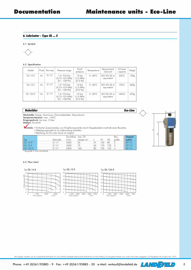
6. Lubricator - Type OL ... E
6.1. Symbol
6.2. Specification
6.3. Flow chart
0,6
0,5
0,4
0,3
0,2
0,1
00 1000 2000 3000
Out
let p
ress
ure
MPa
Flow capacity L/min Flow capacity L/min
Typ OL 14 E0,6
0,5
0,4
0,3
0,2
0,1
00 1500 3000 4500 6000 7500
Flow capacity L/min
Typ OL 124 ETyp OL 12 E0,6
0,5
0,4
0,3
0,2
0,1
00 1000 2000 3000 4000 5000
Model Fluid Port size Pressure range Proof pressure Temperature Recommend
lubricantOil bowlcapacity Weigh
OL 14 E Air G 1/4“ 1,5~9,0 bar(0,15~0,9 MPa)
(21~128 PSi)
15 bar(1,5 MPa)(213 Psi)
5~60°C ISO VG 32 orequivalent
25CC 130g
OL 12 E Air G 1/2“ 1,5~9,0 bar(0,15~0,9 MPa)
(21~128 PSI)
15 bar(1,5 MPa)(213 Psi)
5~60°C ISO VG 32 orequivalent
75CC 360g
OL 124 E Air G 1/2“ 1,5~9,0 bar(0,15~0,9 MPa)
(21~128 PSI)
15 bar(1,5 MPa)(213 Psi)
5~60°C ISO VG 32 orequivalent
160CC 670g
Nebelöler Eco-LineWerkstoffe: Körper: Aluminium, Ölvorratsbehälter: PolycarbonatTemperaturbereich: max. +60°CEingangsdruck: bis max. 10 barMedien: Druckluft
orteile: � Einfacher Zusammenbau von Einzelkomponenten durch Koppelpakete innerhalb einer Baureihe.� Befestigungswinkel ist im Lieferumfang enthalten� Befüllung mit Öl unter Druck ist möglich
H2
H1
L
�Durchfluss max. Öl- Bau-
Typ Gewinde l/min menge cm3 L H1 H2 größeOL 14 E* G 1/4“ 2200 25 47 120 80 2OL 12 E G 1/2“ 4500 75 60 170 125 3OL 124 E G 1/2“ 6300 160 80 192 142 4
* Baugröße 2 ohne Schutzkorb
Koppel-paketKP 2 EKP 3 EKP 4 E

Phone: +49 (0)561/95885 - 9 · Fax: +49 (0)561/95885 - 20 · e-Mail: [email protected]
Alle Angaben verstehen sich als unverbindliche Richtwerte! Für nicht schriftlich bestätigte Datenauswahl übernehmen wir keine Haftung. Druckangaben beziehen sich, soweit nicht anders angegeben, auf Flüssigkeiten der Gruppe II bei +20°C.
9
Documentation Maintenance units - Eco-Line
6.4. Inner structure
6.5. Dimensions
11
109
87
6
5
4
3
2
1
12
1314
15
16
171819
IN OUT
No. Item Material of major parts1 Oil bowl PC2 Adjusting spring3 O-ring4 Lubricator body Aluminium alloy5 Steel ball6 Distance block TPU7 O-ring8 Bowl O-ring9 Indicating ring POM10 Drip pipe PC11 Ejector pin Brass12 Screw13 Adjusting ring POM14 Ejector pin O-ring15 Bowl PC16 Sprayer body17 O-ring18 O-ring19 Sprayer bottom cap
30
Bracket(Select)
1/4”
40
27
8,4
5,4
47
118~
120
8023
A
C
B
G
DE
F
J
HI
Typ OL 14 F
Typ OL 12 F, OL 124 E
Model A B C D E F G H I J
OL 12 E 41 G 1/2“ 53,4 40 8 6,5 60 125 27 168~170
OL 124 E 50 G 1/2“ 64 55 11 8,5 80 142 33,5 189,5~191,5

Phone: +49 (0)561/95885 - 9 · Fax: +49 (0)561/95885 - 20 · e-Mail: [email protected]
Alle Angaben verstehen sich als unverbindliche Richtwerte! Für nicht schriftlich bestätigte Datenauswahl übernehmen wir keine Haftung. Druckangaben beziehen sich, soweit nicht anders angegeben, auf Flüssigkeiten der Gruppe II bei +20°C.
10
Documentation Maintenance units - Eco-Line
7. FR.L combination - Type CL ... E
7.1. Symbol
7.2. Specification
7.3. Pressure and flow chart
7.3.1. Pressure chart
7.3.2. Flow chart
Model Fluid Port size
Filtering grade Pressure range Max
pressureProof
pressureTempera
-tureDrain bowl
capacityOil bowlcapacity
Recommendlubricant Weigh
CL 14 E Air G 1/4“ 5 µ 1,5~9,0 bar(0,15~0,9 MPa)
(21~128 PSi)
10 bar(1,0 MPa)(142 Psi)
15 bar(1,5 MPa)(213 Psi)
5~60°C 10CC 25CC ISO VG32 orequivalent
425g
CL 12 E Air G 1/2“ 5 µ 1,5~9,0 bar(0,15~0,9 MPa)
(21~128 PSI)
10 bar(1,0 MPa)(142 Psi)
15 bar(1,5 MPa)(213 Psi)
5~60°C 40CC 75CC ISO VG32 orequivalent
980g
CL 124 E Air G 1/2“ 5 µ 1,5~9,0 bar(0,15~0,9 MPa)
(21~128 PSI)
10 bar(1,0 MPa)(142 Psi)
15 bar(1,5 MPa)(213 Psi)
5~60°C 80CC 160CC ISO VG32 orequivalent
1950g
0,6
0,5
0,4
0,3
0,2
0,1
00 500 1000 1500 2000 2500 3000
Out
let p
ress
ure
MPa
Flow capacity L/min Flow capacity L/min
Typ CL 14 E0,6
0,5
0,4
0,3
0,2
0,1
00 1500 3000 4500 6000
Flow capacity L/min
Typ CL 124 ETyp CL 12 E0,6
0,5
0,4
0,3
0,2
0,1
00 1000 2000 3000 4000
Intel pressure: 0,7 MPa Intel pressure: 0,7 MPa Intel pressure: 0,7 MPa
0,22
0,18
0,20
0 0,2 0,4 0,6 0,8 1,0
Out
let p
ress
ure
MPa
Inlet pressure MPa
Typ CL 14 E
0,22
0,18
0,20
0 0,2 0,4 0,6 0,8 1,0Inlet pressure MPa
Typ CL 12 E
0,22
0,18
0,20
0 0,2 0,4 0,6 0,8 1,0Inlet pressure MPa
Typ CL 124 E
Set pointSet point Set point
Wartungseinheiten 2-teilig Eco-LineAusführung: Filterregler rücksteuerbar, mit angebautem ÖlerWerkstoffe: Körper: Aluminium, Federhaube: POM, Membrane und Dichtungen: NBR, Behälter: PolycarbonatTemperaturbereich: bis max. +60°CManometeranschluss: G 1/8“ (Baugröße 4: G 1/4“) bzw. Manometer aufgebautPorenweite im Filter: 5 µmEingangsdruck: 1,5 bis 10 barKondensatentleerung: halbautomatisch, durch Umbau des Kondensatbehälters auch automatisch möglichMedien: Druckluft
orteile: � Automatische Entlüftung bei Überdruck auf der Sekundärseite.� Einfacher Zusammenbau von Einzelkomponenten durch Koppelpakete innerhalb einer Baureihe und Ge-
windegröße. � Handrad kann durch Herunterdrücken arretiert werden.� Befestigungswinkel ist im Lieferumfang enthalten� Befüllung mit Öl unter Druck ist möglich
H2
H1
L
�
Druck- max. regel- Durchfluss Kondensat- max. Öl- Bau-
Typ Gewinde bereich l/min menge cm3 menge cm3 L H1 H2 größemit Kompakt-Manometer 0 -10 barCL 14 E* G 1/4“ 1,5 - 9 bar 1500 10 25 97 161 93 2CL 12 E G 1/2“ 1,5 - 9 bar 3800 40 75 124 226 143 3CL 124 E G 1/2“ 1,5 - 9 bar 5300 80 160 164 270 166 4
mit Innengewinde G 1/8“ für Manometer Ø 40 mm (Baugröße 4: G 1/4“ für Manometer Ø 50 mm)CL 14 EB* G 1/4“ 1,5 - 9 bar 1500 10 25 97 161 93 2CL 12 EB G 1/2“ 1,5 - 9 bar 3800 40 75 124 226 143 3CL 124 EB G 1/2“ 1,5 - 9 bar 5300 80 160 164 270 166 4
* Baugröße 2 ohne Schutzkorb
Typ mit Kompaktmanometer

Phone: +49 (0)561/95885 - 9 · Fax: +49 (0)561/95885 - 20 · e-Mail: [email protected]
Alle Angaben verstehen sich als unverbindliche Richtwerte! Für nicht schriftlich bestätigte Datenauswahl übernehmen wir keine Haftung. Druckangaben beziehen sich, soweit nicht anders angegeben, auf Flüssigkeiten der Gruppe II bei +20°C.
11
Documentation Maintenance units - Eco-Line
7.4. Inner structure
7.5. Dimensions
T Shape bracket
G Series Lubricator
G Series Filter-Regulator
Item Material of major partsBody Aluminium alloyUmbrella baftle POMAir guider POMFilter element 5 µ: FiberDrain bowl PCLeak post POMPressure knob POMAdjusting seat POMAdjusting spindle HPB59-1Diaphragm SUS304 covered with rubberPressure spring Stainless steelSpring Stainless steelFilling plug BrassBowl PCEjector pin BrassOil bowl PCBowl guard SPCC
6230
T Sharpe bracket
50
1/4”
AB
F
D
C
E
97
161,
2
93,2
5,5
8,5
G
K
H
I
J
M30x1,5
Typ CL 14 E
Typ CL 12 E, CL 124 E
Model A B C D E F G H I J K
CL 12 E 72 41,5 70 G 1/2“ BSPP1/8 M40x1,5 124 143 6,5 9 225,5
CL 124 E 85,5 50 40 G 1/2“ BSPP1/4 M55x2,0 164 165,5 8,6 12 269,5

Phone: +49 (0)561/95885 - 9 · Fax: +49 (0)561/95885 - 20 · e-Mail: [email protected]
Alle Angaben verstehen sich als unverbindliche Richtwerte! Für nicht schriftlich bestätigte Datenauswahl übernehmen wir keine Haftung. Druckangaben beziehen sich, soweit nicht anders angegeben, auf Flüssigkeiten der Gruppe II bei +20°C.
12
Documentation Maintenance units - Eco-Line
Typ Beschreibung für BaugrößeErsatzfilter für Filter und Filterregler (5 µm)FILTER 2 E Filterfeinheit 5 µm 2FILTER 3 E Filterfeinheit 5 µm 3FILTER 4 E Filterfeinheit 5 µm 4
Ersatzbehälter für Filter und FilterreglerBF 2 E halbautomatischer Ablass 2BF 3 E halbautomatischer Ablass 3BF 3 E AM automatischer Ablass 3BF 4 E halbautomatischer Ablass 4BF 4 E AM automatischer Ablass 4
Ersatzbehälter für ÖlerBOL 2 E 2BOL 3 E 3BOL 4 E 4
Koppelpakete zum Verbinden von Elementen einer Baugröße (mit Befestigung)KP 2 E 2KP 3 E 3KP 4 E 4
Ersatzkompaktmanometer 0-10 barR 14 E MANO 2-4
Ersatzteile für Wartungsgeräte Eco-Line
Typ FILTER
Typ KP
Typ BOL Typ BF
Typ R 14 E MANO
8. Spare parts