dod antiterrorism standards for buildings 10.031
DESCRIPTION
Dod Antiterrorism Standards for Buildings 10.031TRANSCRIPT
UFC 4-010-01 8 October 2003
Including change 1, 19 January 2007
UNIFIED FACILITIES CRITERIA (UFC)
DoD MINIMUM ANTITERRORISM STANDARDS FOR BUILDINGS
DISTRIBUTION STATEMENT A: Approved for Public Release;
Distribution is unlimited.
UFC 4-010-01 8 October 2003
Including change 1, 19 January 2007
UNIFIED FACILITIES CRITERIA (UFC)
DoD MINIMUM ANTITERRORISM STANDARDS FOR BUILDINGS Any copyrighted material included in this UFC is identified at its point of use. Use of the copyrighted material apart from this UFC must have the permission of the copyright holder. DEPUTY UNDER SECRETARY OF DEFENSE (INSTALLATIONS AND ENVIRONMENT) (Preparing Activity) J3, DEPUTY DIRECTORATE FOR ANTITERRORISM AND FORCE PROTECTION, JOINT CHIEFS OF STAFF U.S. ARMY CORPS OF ENGINEERS NAVAL FACILITIES ENGINEERING COMMAND AIR FORCE CIVIL ENGINEER SUPPORT AGENCY Record of Changes (changes are indicated by \1\ ... /1/) Change No. Date Location 1 January 2007 See change summary sheet for details _____________ This UFC supersedes UFC 4-010-01 of 8 October 2003.

UFC 4-010-01 8 October 2003
Including change 1, 19 January 2007
FOREWORD The Unified Facilities Criteria (UFC) system is prescribed by MIL-STD 3007 and provides planning, design, construction, sustainment, restoration, and modernization criteria, and applies to the Military Departments, the Defense Agencies, and the DoD Field Activities in accordance with USD(AT&L) Memorandum dated 29 May 2002. UFC will be used for all DoD projects and work for other customers where appropriate. All construction outside of the United States is also governed by Status of forces Agreements (SOFA), Host Nation Funded Construction Agreements (HNFA), and in some instances, Bilateral Infrastructure Agreements (BIA.) Therefore, the acquisition team must ensure compliance with the more stringent of the UFC, the SOFA, the HNFA, and the BIA, as applicable. UFC are living documents and will be periodically reviewed, updated, and made available to users as part of the Services’ responsibility for providing technical criteria for military construction. Headquarters, U.S. Army Corps of Engineers (HQUSACE), Naval Facilities Engineering Command (NAVFAC), and Air Force Civil Engineer Support Agency (AFCESA) are responsible for administration of the UFC system. Defense agencies should contact the preparing service for document interpretation and improvements. Technical content of UFC is the responsibility of the cognizant DoD working group. Recommended changes with supporting rationale should be sent to the respective service proponent office by the following electronic form: Criteria Change Request (CCR). The form is also accessible from the Internet sites listed below. UFC are effective upon issuance and are distributed only in electronic media from the following source: • Whole Building Design Guide web site http://dod.wbdg.org/. Hard copies of UFC printed from electronic media should be checked against the current electronic version prior to use to ensure that they are current. AUTHORIZED BY: ______________________________________ Donald Basham, P.E. Chief, Engineering and Construction Division U.S. Army Corps of Engineers
______________________________________Dr. James W Wright, P.E. Chief Engineer Naval Facilities Engineering Command
______________________________________ Kathleen I. Ferguson, P.E. The Deputy Civil Engineer DCS/Installations & Logistics Department of the Air Force
______________________________________Dr. Get W Moy, P.E. Director, Installations Requirements and Management Office of the Deputy Under Secretary of Defense (Installations and Environment)

UFC 4-010-01 8 October 2003
Including change 1, 19 January 2007
FOREWORD (continued)
This specific document is also issued under the authority of DoD Instruction Number 2000.16, DoD Antiterrorism Standards which requires DoD Components to adopt and adhere to common criteria and minimum construction standards to mitigate antiterrorism vulnerabilities and terrorist threats. In addition, this document was further implemented by a USD(AT&L) Memorandum dated 20 September 2002. This document applies to the Office of the Secretary of Defense (OSD); the Military Departments (including their National Guard and Reserve Components); the Chairman, Joint Chiefs of Staff and Joint Staff; the Combatant Commands; the Office of the Inspector General of the Department of Defense; the Defense Agencies; the Department of Defense Field Activities; and all other organizational entities within the Department of Defense hereafter referred to collectively as “the DoD Components.” The standards established by this document are minimums set for DoD. Each DoD Component may set more stringent antiterrorism building standards to meet the specific threats in its area of responsibility. Any changes, updates, or amendments to this particular UFC must have the approval of the DoD Engineering Senior Executive Panel (ESEP). This document is effective immediately and is mandatory for use by all the DoD Components.
UFC 4-010-01 8 October 2003
Including change 1, 19 January 2007
Unified Facilities Criteria (UFC) Change Summary Sheet
Subject: UFC 4-010-01, DoD Minimum Antiterrorism Standards for Buildings Cancels: UFC 4-010-01, DoD Minimum Antiterrorism Standards for Buildings, Dated 08 October 2003 Description of Change(s):
• Editorial and typographic corrections throughout.
Chapter 1 – Introduction
• 1-1.2.2 Installation Commanders. Added information regarding guidance and requirements established by combatant commanders – i.e. EUCOM, PACOM, CENTCOM, SOUTHCOM.
• 1-1.2.4 Geographic Combatant Commanders. New paragraph outlining responsibilities for establishing additional guidance ensuring a uniform and consistent application of these standards within their areas of operations or to account for any special circumstances that apply within their areas of operations.
• Additional References - Added the following: o Unified Facilities Criteria (UFC) 4-023-03, Design of Buildings to Resist
Progressive Collapse (reference for Standard 6 – Progressive Collapse Avoidance)
o ASTM Standard E1300-04e1, Standard Practice for Determining Load Resistance of Glass in Buildings (reference for Standard 10 – Windows, Skylights and Glazed Doors)
o ASTM Standard F1642-04, Standard Test Method for Glazing and Glazing Systems Subject to Airblast Loadings (reference for Standard 10 – Windows, Skylights and Glazed Doors)
o ASTM Standard F2248-03, Standard Practice for Specifying an Equivalent 3-Second Duration Design Loading for Blast Resistant Glazing Fabricated with Laminated Glass (reference for Standard 10 – Windows, Skylights and Glazed Doors)
• 1-3 Standards and Recommendations: Added explanation that these standards are a combination of performance and prescriptive requirements, where in many cases the prescriptive requirements (standoff, glazing thickness) are based on performance standards set forth in other documents.
• 1-4 Intent: Added explanation on the intent of these standards with regards to bringing existing buildings into compliance over time as major investments are made in them or as leases are renewed such that eventually all inhabited DoD buildings comply with these standards.
• 1-6 Applicability: Editorial changes and additions: Added “high occupancy family housing” – and added definition to Appendix A; Changed “uninhabited” to

UFC 4-010-01 8 October 2003
Including change 1, 19 January 2007
“low occupancy” and added definition to Appendix A; Added “Tenant Buildings on DoD Installations”.
Chapter 2 – Philosophy, Design Strategies, and Assumptions
• 2-4.4 Levels of Protection: Added the following – “The potential levels of
protection are described qualitatively in Tables 2-1 and 2-2. Those descriptions should be used for general understanding of the goals of the levels of protection. Detailed, quantitative descriptions of the levels of protection are included in the DoD Security Engineering Facilities Design Manual.”
• Table 2-1 Levels of Protection – New and Existing Buildings and Table 2-2, Levels of Protection – Expeditionary and Temporary Structures: Revised the more quantitative description of potential damage and building performance to a more qualitative description. Added notes to both tables to assist reader better understand the levels of protection and direct reader to references with additional information on damage and performance levels.
Appendix A – Definitions
• Deleted the following: These definitions are found in other DoD UFC’s,
instructions, directives, standards, and manuals. o Collaterally protected construction o Hardened Construction o Protected Construction o Semi-hardened construction o Splinter protected construction.
• Added/Changed/Modified the following: o Building overhangs o Force Protection Condition (FPCON), o High occupancy family housing, o Low occupancy building o Renamed and Changed “Effective Standoff Distance” to “Minimum standoff
distance”; Clarified through rewrite and addition – Conventional construction, DoD building, Mail room, and Primary gathering building.

UFC 4-010-01 8 October 2003
Including change 1, 19 January 2007
Appendix B – DoD Minimum Antiterrorism Standards for New and Existing Buildings
• B-1.1 Standard 1. Standoff Distances: Changed name by deleting “Minimum” and modified wording in accordance with new and clarified definitions in Appendix A.
• Table B-1 Standoff Distances for New and Existing Buildings: Changed name by deleting “Minimum” and modified wording in accordance with new and clarified definitions in Appendix A.
• Added Figure B-3, Parking and Roadway Control for Existing Buildings – Controlled Perimeter and Figure B-4, Parking and Roadway Control for Existing Buildings – No Controlled Perimeter
• B-2.1 Standard 6 Progressive Collapse Avoidance: Complete rewrite of this standard in accordance with UFC 4-023-03, Design of Building to Resist Progressive Collapse, published 25 January 2005.
• B-2.3 Standard 8. Building Overhangs: Clarified with regards to existing buildings and added a paragraph for “Adjacent Building Elements”.
• B-2.4 Standard 9. Exterior Masonry Walls: Complete rewrite of this standard, providing for both vertical and horizontal reinforcement and distribution of reinforcement.
• B-3.1 Standard 10. Windows, and Skylights: o Changed from “Windows, and Skylights, and Glazed Doors” o Completely rewrote this standard in accordance with the design and testing
requirements of ASTM Standard E1300-04, Standard Practice for Determining Load Resistance of Glass in Buildings, ASTM Standard F1642-04, Standard Test Method for Glazing and Glazing Systems Subject to Airblast Loadings, ASTM Standard F2248-03, Standard Practice for Specifying an Equivalent 3-Second Duration Design Loading for Blast Resistant Glazing Fabricated with Laminated Glass; with slight modifications made necessary by conservatism in ASTM E1300-04 and F2248-03.
o Added two tables to reflect the modifications to the application of ASTM E1300-04 and F2248-03: Table B-2, Laminated Glass Thickness Selection for Single Pane Windows and Table B-3, Laminated Glass Thickness Selection for Insulating Glass Unit (IGU) Windows
o Provided additional information on: Alternative Window Treatments, New Buildings and Existing Buildings Undergoing Major Renovation, Leased Buildings, and Other Existing Buildings.
• B-3.3. Standard 12. Exterior Doors. Moved all discussion on glazed doors from Standard 10 to this standard and made treatment of glazed doors consistent with treatment of windows.
• B-3.4 Standard 13. Mail Rooms: Added the following for clarification – “These standards need not be applied to mail rooms to which mail is delivered that was initially delivered to a central mail handling facility. These standards should be

UFC 4-010-01 8 October 2003
Including change 1, 19 January 2007
applied to such mail rooms where possible, however, to account for potential changes in mail handling procedures over the life of the building.”
• B-4.3 Standard 18. Emergency Air Distribution Shutoff: Added paragraphs for “Outside Air Intakes and Exhausts” and “Critical Areas”
Appendix C – Recommended Additional Antiterrorism Measures for New and Existing Buildings
• Various modifications and clarifications accounting for changes and addition of definitions in Appendix A.
Appendix D – DoD Minimum Antiterrorism Standards for Expeditionary and Temporary Structures
• D-1.1 Standard 1. Standoff Distances: Changed name by deleting “Minimum” and modified wording in accordance with new and clarified definitions in Appendix A. Added the following: “Note that container structures and pre-engineered buildings respond similarly to other buildings, so they are separated from the other expeditionary and temporary structures below. Of the remaining expeditionary and temporary structure types, the two structure types in Table D-1 respond in fundamentally different ways to explosive effects.”
• D-1.2.1.1 Container Structures and Pre-Engineered Buildings: Complete rewrite: “For these structures, ensure that adjacent inhabited structures are separated by at least 10 meters. Where it is necessary to encroach on that separation distance, analyze the structure and harden structure components as necessary to mitigate the effects of the explosive indicated in Table D-1 to the appropriate level of protection shown in Table B-1. Levels of protection are described in Table 2-1 and in the DoD Security Engineering Facilities Planning Manual.”
• D-2.1 (New Paragraph) Container Structures and Pre-engineered Buildings. For these structures, all standards in Appendix B apply.
• Table D-1 Standoff Distances and Separation for Expeditionary and Temporary Structures: Changed name by deleting “Minimum” and modified wording in accordance with new and clarified definitions in Appendix A.

UFC 4-010-01 8 October 2003
Including change 1, 19 January 2007
i
CONTENTS
Page CHAPTER 1 INTRODUCTION Paragraph 1-1 GENERAL ................................................................................ 1-1 1-1.1 Dynamic Threat Environment ................................................... 1-1 1-1.2 Responsibility ........................................................................... 1-1 1-1.3 Planning and Integration........................................................... 1-2
1-2 REFERENCES......................................................................... 1-2 1-3 STANDARDS AND RECOMMENDATIONS............................. 1-3 1-4 INTENT .................................................................................... 1-3 1-5 LEVELS OF PROTECTION ..................................................... 1-4 1-5.1 DoD Component Standards ..................................................... 1-4 1-5.2 Threat-Specific Requirements .................................................. 1-4 1-5.3 Critical Facilities ....................................................................... 1-4 1-5.4 Explosive Safety Standards...................................................... 1-4 1-6 APPLICABILITY ....................................................................... 1-5 1-6.1 New Construction ..................................................................... 1-5 1-6.2 Existing Buildings ..................................................................... 1-5 1-6.3 Building Additions..................................................................... 1-6 1-6.4 Leased Buildings ...................................................................... 1-6 1-6.5 Expeditionary and Temporary Structures ................................. 1-6 1-6.6 National Guard Buildings.......................................................... 1-7 1-6.7 Tenant Buildings on DoD Installations...................................... 1-7 1-6.8 Exemptions............................................................................... 1-7
1-7 PROGRAMMING ..................................................................... 1-8 1-7.1 Documentation ......................................................................... 1-8
1-7.2 Funding Thresholds.................................................................. 1-8 1-8 INFORMATION SENSITIVITY ................................................. 1-8 1-8.1 Distribution ............................................................................... 1-8 1-8.2 Posting to the Internet .............................................................. 1-8 1-8.3 Plans and Specifications .......................................................... 1-91-8.4 Design-Build Contracts............................................................. 1-9 1-9 HISTORIC PRESERVATION COMPLIANCE........................... 1-9 1-9.1 Security and Stewardship......................................................... 1-9 1-9.2 Compliance with Laws.............................................................. 1-9 1-9.3 Compliance with DoD Standards............................................ 1-9 1-9.4 Designation of National Emergency ....................................... 1-10 1-10 INTERIM DESIGN GUIDANCE .............................................. 1-10
CHAPTER 2 PHILOSOPHY, DESIGN STRATEGIES, AND ASSUMPTIONS Paragraph 2-1 GENERAL ................................................................................ 2-1
2-2 PHILOSOPHY .......................................................................... 2-1 2-2.1 Time ......................................................................................... 2-1 2-2.2 Master Planning ....................................................................... 2-1
UFC 4-010-01 8 October 2003
Including change 1, 19 January 2007
ii
2-2.3 Design Practices ...................................................................... 2-1 2-3 DESIGN STRATEGIES............................................................ 2-2 2-3.1 Maximize Standoff Distance ..................................................... 2-2 2-3.2 Prevent Building Collapse ........................................................ 2-2 2-3.3 Minimize Hazardous Flying Debris ........................................... 2-2 2-3.4 Provide Effective Building Layout ............................................. 2-2 2-3.5 Limit Airborne Contamination ................................................... 2-32-3.6 Provide Mass Notification ......................................................... 2-3 2-3.7 Facilitate Future Upgrades ....................................................... 2-3 2-4 ASSUMPTIONS ....................................................................... 2-3 2-4.1 Baseline Threat ........................................................................ 2-3 2-4.2 Controlled Perimeters............................................................... 2-4 2-4.3 Government Vehicle Parking.................................................... 2-5 2-4.4 Levels of Protection.................................................................. 2-5 2-4.5 Standoff Distances ................................................................... 2-5 2-4.6 Exempted Building Types......................................................... 2-8 2-4.7 Policies and Procedure.............................................................2-9 2-4.8 Design Criteria....................................................................... 2-10 2-4.9 Enhanced Fire Safety ............................................................ 2-10 2-4.10 Training ................................................................................. 2-10 2-4.11 Expeditionary and Temporary Structures .............................. 2-10 2-4.12 Leased Buildings ................................................................... 2-10
APPENDIX A DEFINITIONS...........................................................................A-1 APPENDIX B DoD ANTITERRORISM STANDARDS FOR NEW AND EXISTING BUILDINGS ...............................................................................................B-1 Paragraph B-1 SITE PLANNING ......................................................................B-1 B-1.1 Standard 1. Standoff Distances...............................................B-1 B-1.2 Standard 2. Unobstructed Space ............................................B-7 B-1.3 Standard 3. Drive-Up/Drop-Off Areas......................................B-7 B-1.4 Standard 4. Access Roads ......................................................B-8 B-1.5 Standard 5. Parking Beneath Buildings or on Rooftops...........B-8 B-2 STRUCTURAL DESIGN...........................................................B-8 B-2.1 Standard 6. Progressive Collapse Avoidance .........................B-8 B-2.2 Standard 7. Structural Isolation ...............................................B-9 B-2.3 Standard 8. Building Overhangs..............................................B-9 B-2.4 Standard 9. Exterior Masonry Walls .......................................B-10 B-3 ARCHITECTURAL DESIGN....................................................B-10 B-3.1 Standard 10. Windows and Skylights .....................................B-10 B-3.2 Standard 11. Building Entrance Layout ..................................B-16 B-3.3 Standard 12. Exterior Doors ...................................................B-16 B-3.4 Standard 13. Mail Rooms .......................................................B-16 B-3.5 Standard 14. Roof Access......................................................B-17 B-3.6 Standard 15. Overhead Mounted Architectural Features .......B-17

UFC 4-010-01 8 October 2003
Including change 1, 19 January 2007
iii
B-4 ELECTRICAL AND MECHANICAL DESIGN...........................B-17 B-4.1 Standard 16. Air Intakes .........................................................B-17 B-4.2 Standard 17. Mail Room Ventilation B-18 B-4.3 Standard 18. Emergency Air Distribution Shutoff B-18 B-4.4 Standard 19. Utility Distribution and Installation B-19 B-4.5 Standard 20. Equipment Bracing B-19 B-4.6 Standard 21. Under Building Access B-19 B-4.7 Standard 22. Mass Notification B-19 APPENDIX C RECOMMENDED ADDITIONAL ANTITERRORISM MEASURES FOR NEW AND EXISTING BUILDINGS .............................................................................C-1 Paragraph C-1. SITE PLANNING ......................................................................C-1 C-1.1 Recommendation 1. Vehicle Access Points ............................C-1 C-1.2 Recommendation 2. High-Speed Vehicle Approach ...............C-1 C-1.3 Recommendation 3. Vantage Points .......................................C-1 C-1.4 Recommendation 4. Drive-Up/Drop-Off Areas ........................C-1 C-1.5 Recommendation 5. Building Location ....................................C-1 C-1.6 Recommendation 6. Railroad Location....................................C-1 C-1.7 Recommendation 7. Access Control for Family Housing.........C-2 C-1.8 Recommendation 8. Standoff for Family Housing ...................C-2 C-1.9 Recommendation 9. Minimize Secondary Debris....................C-2 C-1.10 Recommendation 10. Building Separation ..............................C-2 C-2 STRUCTURAL AND ARCHITECTURAL DESIGN ...................C-2 C-2.1 Recommendation 11. Structural Redundancy .........................C-3 C-2.2 Recommendation 12. Internal Circulation................................C-3 C-2.3 Recommendation 13. Visitor Control .......................................C-3 C-2.4 Recommendation 14. Asset Location......................................C-3 C-2.5 Recommendation 15. Room Layout ........................................C-3 C-2.6 Recommendation 16. External Hallways .................................C-3 C-2.7 Recommendation 17. Windows...............................................C-3 APPENDIX D DoD ANTITERRORISM STANDARDS FOR EXPEDITIONARY AND TEMPORARY STRUCTURES ....................................................................................D-1 Paragraph D-1 SITE PLANNING STANDARDS ...............................................D-1 D-1.1 Standard 1. Standoff Distances...............................................D-1 D-1.2 Standard 2. Structure Separation ............................................D-3 D-1.3 Standard 3. Unobstructed Space ............................................D-3 D-2 ADDITIONAL STANDARDS.....................................................D-3 D-2.1 Container Structures and Pre-Engineered Buildings ................D-3 D-2.2 Fabric Covered and other Expeditionary or Temporary Structures .................................................................................D-3 D-3 ANTITERRORISM RECOMMENDATIONS..............................D-4
UFC 4-010-01 8 October 2003
Including change 1, 19 January 2007
iv
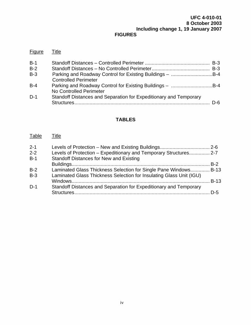
FIGURES Figure Title B-1 Standoff Distances – Controlled Perimeter ............................................... B-3 B-2 Standoff Distances – No Controlled Perimeter.......................................... B-3 B-3 Parking and Roadway Control for Existing Buildings – ..............................B-4 Controlled Perimeter B-4 Parking and Roadway Control for Existing Buildings – ..............................B-4 No Controlled Perimeter D-1 Standoff Distances and Separation for Expeditionary and Temporary Structures.................................................................................................. D-6
TABLES
Table Title 2-1 Levels of Protection – New and Existing Buildings.................................... 2-6 2-2 Levels of Protection – Expeditionary and Temporary Structures............... 2-7 B-1 Standoff Distances for New and Existing
Buildings.................................................................................................... B-2 B-2 Laminated Glass Thickness Selection for Single Pane Windows.............. B-13 B-3 Laminated Glass Thickness Selection for Insulating Glass Unit (IGU) Windows.................................................................................................... B-13 D-1 Standoff Distances and Separation for Expeditionary and Temporary
Structures.................................................................................................. D-5

UFC 4-010-01 8 October 2003
Including change 1, 19 January 2007
1-1
CHAPTER 1
INTRODUCTION
1-1 GENERAL. This UFC represents a significant commitment by DoD to seek effective ways to minimize the likelihood of mass casualties from terrorist attacks against DoD personnel in the buildings in which they work and live.
1-1.1 Dynamic Threat Environment. Terrorism is real, evolving, and continues to increase in frequency and lethality throughout the world. The unyielding, tenacious, and patient nature of the terrorists targeting DoD interests forces us to closely examine existing policies and practices for deterring, disrupting, and mitigating potential attacks. Today, terrorist attacks can impact anyone, at any time, at any location, and can take many forms. Deterrence against terrorist attacks begins with properly trained and equipped DoD personnel employing effective procedures. While terrorists have many tactics available to them, they frequently use explosive devices when they target large numbers of DoD personnel. Most existing DoD buildings offer little protection from terrorist attacks. By applying the Minimum Antiterrorism Standards for Buildings described in this UFC, we become a lesser target of opportunity for terrorists.
1-1.2 Responsibility. Protecting people on a DoD installation or site must start with an understanding of the risk of a terrorist attack. Application of the standards herein should be consistent with the perceived or identified risk. Everyone in DoD is responsible for protecting our people and other resources.
1-1.2.1 Individuals. Each DoD employee, contractor, or vendor is responsible for minimizing opportunities for terrorists to threaten or target themselves, their co-workers, and their families on DoD installations or sites.
1-1.2.2 Installation Commanders. The installation commander must protect the people on his or her installation or site by managing and mitigating the risk to those people in the event of a terrorist attack. The installation commander is responsible for applying the standards herein, consistent with the identified or perceived risk of people being hurt or killed and with the implementing guidance established by the applicable Service or Agency and the geographic combatant commander for the area of responsibility within which the installation is located where that combatant commander has established additional guidance or requirements. The installation commander will obtain prior approval consistent with Service or Agency guidance if any new construction project, renovation project, or leased facility to which these standards apply will not meet any one or more of these standards. Lack of funding alone will not be cause to reduce any standard.
1-1.2.3 Service Secretaries and Agency Heads. Service Secretaries and Agency Heads will ensure compliance with these standards and will issue guidance for their implementation. That guidance will include direction to require the installation commander to notify or seek approval from a major command or claimant or higher headquarters level if a new construction of renovation project, or a leased facility, will
UFC 4-010-01 8 October 2003
Including change 1, 19 January 2007
1-2
not meet any one or more of the standards. Heads of DoD Components will establish plans and procedures to mitigate risks in such situations. 1-1.2.4 Geographic Combatant Commanders. Geographic combatant commanders may establish additional guidance to ensure uniform and consistent application of these standards within their areas of operations or to account for any special circumstances. 1-1.3 Planning and Integration. When the best procedures, proper training, and appropriate equipment fail to deter terrorist attacks, adherence to these standards goes far in mitigating the possibility of mass casualties from terrorist attacks against DoD personnel in the buildings in which they work and live. Although predicting the specific threat to everyone is not possible, proper planning and integration of those plans provides a solid foundation for preventing, and if necessary reacting, when terrorist incidents or other emergencies unfold. An effective planning process facilitates the necessary decision making, clarifies roles and responsibilities, and ensures support actions generally go as planned. A team consisting of the chain of command and key personnel from all appropriate functional areas who have an interest in the building and its operation executes this planning process. The team should include, as a minimum, antiterrorism/force protection, intelligence, security, and facility engineering personnel. This team is responsible for identifying requirements for the project, facilitating the development of supporting operational procedures, obtaining adequate resources, and properly supporting all other efforts needed to prudently enhance protection of the occupants of every inhabited DoD building. For further information on planning and integration, refer to the DoD Security Engineering Facilities Planning Manual.
1-2 REFERENCES.
• Interim Department of Defense Antiterrorism / Force Protection Construction Standards, December 16, 1999 (hereby cancelled)
• DoD Instruction 2000.16, DoD Antiterrorism Standards, June 14, 2001.
• DoD Handbook 2000.12-H, DoD Antiterrorism Handbook, 9 February 2004 (For Official Use Only (FOUO))
• American Society of Civil Engineers Standard (ASCE/SEI) 7-05, Minimum Design Loads for Buildings and Other Structures, 2006
• Unified Facilities Criteria (UFC) 4-010-02, DoD Minimum Antiterrorism Standoff Distances for Buildings; (For Official Use Only (FOUO))
• Unified Facilities Criteria (UFC) 4-020-01, DoD Security Engineering Facilities Planning Manual
• Unified Facilities Criteria (UFC) 4-020-02, DoD Security Engineering Facilities Design Manual, (Draft)

UFC 4-010-01 8 October 2003
Including change 1, 19 January 2007
1-3
• Sections 2805(a)(1) and 2805(c)(1) of Title 10, US Code
• Security Engineering Working Group web site (https://sewg.dtic.mil)
• DoD 6055.9-STD, DoD Ammunition and Explosive Safety Standards, 5 October 2004
• SHAPE Document 6160/SHLOFA-059/82, NATO Approved Criteria and Standards for Tactical and Transport Airfields (6th Addition), 30 March 1982 (NATO Restricted)
• Unified Facilities Criteria (UFC) 4-021-01, Mass Notification Systems, 18 December 2002
• Unified Facilities Criteria (UFC) 4-023-03, Design of Buildings to Resist Progressive Collapse, 25 January 2005
• ASTM Standard E1300-04, Standard Practice for Determining Load Resistance of Glass in Buildings
• ASTM Standard F1642-04, Standard Test Method for Glazing and Glazing Systems Subject to Airblast Loadings
• ASTM Standard F2248-03, Standard Practice for Specifying an Equivalent 3-Second Duration Design Loading for Blast Resistant Glazing Fabricated with Laminated Glass
1-3 STANDARDS AND RECOMMENDATIONS. Mandatory DoD minimum antiterrorism standards for new and existing inhabited buildings are contained in Appendix B. Additional recommended measures for new and existing inhabited buildings are included in Appendix C. Mandatory DoD minimum antiterrorism standards for expeditionary and temporary structures are contained in Appendix D. The standards and recommendations in this UFC include a combination or performance and prescriptive requirements. In many cases where there are minimum prescriptive requirements such as standoff distance or glazing thickness, those requirements are based on performance standards and there are generally provisions to allow those performances to be provided through alternate means where those means will result in equivalent levels of protection.
1-4 INTENT. The intent of these standards is to minimize the possibility of mass casualties in buildings or portions of buildings owned, leased, privatized, or otherwise occupied, managed, or controlled by or for DoD. These standards provide appropriate, implementable, and enforceable measures to establish a level of protection against terrorist attacks for all inhabited DoD buildings where no known threat of terrorist activity currently exists. While complete protection against all potential threats for every inhabited building is cost prohibitive, the intent of these standards can be achieved through prudent master planning, real estate acquisition, and design and construction practices.

UFC 4-010-01 8 October 2003
Including change 1, 19 January 2007
1-4
Where the conventional construction standoff distances detailed in these standards are met, most conventional construction techniques can be used with only marginal impact on the total construction or renovation cost. The financial impact of these standards will be significantly less than the economic and intangible costs of a mass casualty event.
While it is feasible to apply these standards to new construction as of the effective dates established herein, applying them to all existing construction and to all leased facilities as of those dates would not be feasible. The intent, therefore, is to bring existing buildings into compliance with these standards over time as major investments are made in them or as leases are renewed such that eventually all inhabited DoD buildings comply with these standards.
1-5 LEVELS OF PROTECTION. The levels of protection provided by these standards meet the intent described above and establish a foundation for the rapid application of additional protective measures in a higher threat environment. These standards may be supplemented where specific terrorist threats are identified, where more stringent local standards apply, or where local commanders dictate additional measures. Detailed descriptions of the levels of protection are provided in Chapter 2 and UFC 4-020-01.
1-5.1 DoD Component Standards. Where DoD Component standards such as geographic Combatant Commander standards address unique requirements, those standards will be incorporated in accordance with their implementing directives, but not to the exclusion of these standards.
1-5.2 Threat-Specific Requirements. Where a design basis threat is identified whose mitigation requires protective measures beyond those required by these standards or DoD Component standards, those measures will be developed in accordance with the provisions of UFC 4-020-01. The provisions of UFC 4-020-01 include the design criteria that will be the basis for the development of the protective measures, estimates of the costs of those measures, and detailed guidance for developing the measures required to mitigate the identified threat. The design criteria include the assets to be protected, the threat to those assets, and the desired level of protection. Use of UFC 4-020-01 will ensure uniform application, development, and cost estimation of protective measures throughout DoD.
1-5.3 Critical Facilities. Buildings that must remain mission operational during periods of national crisis and/or if subjected to terrorist attack should be designed to significantly higher levels of protection than those provided by these standards.
1-5.4 Explosive Safety Standards. These antiterrorism standards establish criteria to minimize the potential for mass casualties and progressive collapse from a terrorist attack. DoD 6055.9-STD, DoD Ammunition and Explosive Safety Standards as implemented by Service component explosive safety standards, establish acceptable levels of protection for accidental explosions of DoD-titled munitions. The explosive safety and antiterrorism standards address hazards associated with unique events;

UFC 4-010-01 8 October 2003
Including change 1, 19 January 2007
1-5
therefore, they specify different levels of protection. Compliance with both standards is required. Where conflicts arise, the more stringent criteria will govern.
1-6 APPLICABILITY. These standards apply to all DoD Components, to all DoD inhabited buildings, billeting, and high occupancy family housing, and to all DoD expeditionary and temporary structures in accordance with the following:
1-6.1 New Construction. Implementation of these standards is mandatory for all new construction regardless of funding source in accordance with the following:
1-6.1.1 Military Construction (MILCON). These standards apply to MILCON projects starting with the Fiscal Year 2004 Program. Projects programmed or designed under the Interim DoD Antiterrorism / Force Protection Construction Standards do not have to be reprogrammed or redesigned to meet the requirements of these standards. The provisions of the Interim Standards will apply to those projects. Due to minor changes between these standards and the Interim Standards, projects prior to the Fiscal Year 2004 Program should comply with these standards where possible.
1-6.1.2 Host-Nation and Other Foreign Government Funding. These standards apply to new construction funded under host-nation agreements or from other funding sources starting in Fiscal Year 2004 or as soon as negotiations with the foreign governments can be completed.
1-6.1.3 Other Funding Sources. These standards apply to all new construction projects funded by sources other than MILCON (such as Non-Appropriated Funds, Operations and Maintenance, and Working Capital Funds) starting with Fiscal Year 2004. Projects funded prior to that fiscal year should comply with these standards where possible.
1-6.2 Existing Buildings. These standards will apply to existing facilities starting with the Fiscal Year 2004 program when triggered as specified below, regardless of funding source. Projects funded prior to that fiscal year should comply with these standards where possible. For existing leased buildings see paragraph 1-6.4.
1-6.2.1 Major Investments. Implementation of these standards to bring an entire building into compliance is mandatory for all DoD building renovations, modifications, repairs, and restorations where those costs exceed 50% of the replacement cost of the building except as otherwise stated in these standards. The 50% cost is exclusive of the costs identified to meet these standards. Where the 50% threshold is not met, compliance with these standards is recommended.
1-6.2.2 Conversion of Use. Implementation of these standards is mandatory when any portion of a building is modified from its current use to that of an inhabited building, billeting, high occupancy family housing, or a primary gathering building for one year or more. Examples would include a warehouse (low occupancy) being converted to administrative (inhabited) use and an inhabited administrative building being converted to a primary gathering building or billeting.

UFC 4-010-01 8 October 2003
Including change 1, 19 January 2007
1-6
1-6.2.3 Glazing Replacement. Because of the significance of glazing hazards in a blast environment, implementation of the glazing provisions of these standards is mandatory for existing inhabited buildings within any planned window or door glazing replacement project, regardless of whether that project meets the 50% cost trigger above. Such replacements may require window frame modification or replacement.
1-6.3 Building Additions. Inhabited additions to existing inhabited buildings will comply with the minimum standards for new buildings. If the addition is 50% or more of the gross area of the existing building, the existing building will comply with the minimum standards for existing buildings in Appendix B.
1-6.4 Leased Buildings. DoD personnel occupying leased buildings deserve the same level of protection as those in DoD-owned buildings. Implementation of these standards is therefore mandatory for all facilities leased for DoD use and for those buildings in which DoD receives a space assignment from another government agency except as established below. This requirement is intended to cover all situations, including General Services Administration space, privatized buildings, and host-nation and other foreign government buildings. This requirement is applicable for all new leases executed on or after 1 October 2005 and to renewal or extension of any existing lease on or after 1 October 2009. Leases executed prior to the above fiscal years will comply with these standards where possible.
1-6.4.1 Partial Occupancy. These standards only apply where DoD personnel occupy leased or assigned space constituting at least 25% of the net interior useable area or the area as defined in the lease, and they only apply to that portion of the building that is occupied by DoD personnel.
1-6.4.2 New Buildings. Buildings that are built to lease to DoD as of the effective date established above will comply with the standards for new construction.
1-6.4.3 Existing Buildings. New leases or renewals of leases of existing buildings will trigger the minimum standards for existing buildings in accordance with the effective dates established above.
1-6.5 Expeditionary and Temporary Structures. Implementation of these standards is mandatory for all expeditionary and temporary structures that meet the occupancy criteria for inhabited or primary gathering buildings or billeting. See Appendix D for structure types that meet the expeditionary and temporary structures criteria.
1-6.5.1 New Structures. These standards apply to all new expeditionary sites effective immediately.
1-6.5.2 Existing Structures. These standards will apply to all existing expeditionary activities beginning in Fiscal Year 2004. Prior to that fiscal year, existing expeditionary structures should comply with these standards where possible.

UFC 4-010-01 8 October 2003
Including change 1, 19 January 2007
1-7
1-6.6 National Guard Buildings. Any National Guard building that uses Federal funding for new construction, renovations, modifications, repairs, restorations, or leasing and that meets the applicability provisions above, will comply with these standards.
1-6.7 Tenant Buildings on DoD Installations. Because buildings built by tenants on DoD installations may be taken over by DoD during their life cycles, memoranda of understanding or similar agreements between DoD components and tenants will require tenant-built buildings to comply with these standards, regardless of funding source. For the purposes of these standards, tenant-built building occupancies will be calculated assuming that building occupants are DoD personnel.
1-6.8 Exemptions. Unless DoD Components dictate otherwise, the following buildings are exempt from requirements of these standards as specified below. However, compliance with these standards for those buildings is recommended where possible. In addition, there are some exemptions to elements of individual standards that are included in the text of those standards in appendix B. The rationale for all exemptions is detailed in chapter 2.
1-6.8.1 Family Housing with 12 Units or Fewer per Building. These buildings are exempt from all provisions of these standards.
1-6.8.2 Stand-Alone Franchised Food Operations. These buildings are exempt from standoff distances to parking and roadways. All other standards apply.
1-6.8.3 Stand Alone Shoppettes, Mini Marts and Similarly Sized Commissaries. These buildings are exempt from standoff distances to parking and roadways. All other standards apply.
1-6.8.4 Small Stand-Alone Commercial Facilities. Stand-alone commercial facilities similar in size to those in paragraph 1-6.8.3 and that have similar operational requirements are exempt from standoff distances to parking and roadways. All other standards apply. An example of such a commercial facility would be a bank with a drive-through window.
1-6.8.5 Gas Stations and Car Care Centers. These facilities are exempt from all provisions of these standards.
1-6.8.6 Medical Transitional Structures and Spaces. These structures are exempt from standoff distances to parking and roadways. All other standards apply.
1-6.8.7 Other Transitional Structures and Spaces. Transitional structures and spaces that will be occupied for less than one year and that are not billeting, high occupancy family housing, primary gathering buildings, or medical transitional structures, are exempt from standoff distances to parking and roadways. All other standards apply.

UFC 4-010-01 8 October 2003
Including change 1, 19 January 2007
1-8
1-6.8.8 Recruiting Stations in Leased Spaces. Recruiting stations located in leased spaces are exempt from all provisions of these standards.
1-6.8.9 Military Protective Construction. Facilities designed to the North Atlantic Treaty Organization (NATO) (or equivalent) standards for collaterally protected, semi-hardened, protected, and hardened facilities are exempt from all provisions of these standards; however, the threats included in this standard should be incorporated into the design criteria for the military protective construction. (Refer to SHAPE document 6160/SHLOFA-059-82.)
1-7 PROGRAMMING.
1-7.1 Documentation. The inclusion of these standards into DoD construction or the inclusion of protective measures above the requirements of these standards will be incorporated into the appropriate construction programming documents (such as the DD Form 1391) in accordance with DoD Component guidance. Refer to UFC 4-020-01 for guidance on the costs for implementing these standards and for providing protective measures beyond these standards.
1-7.2 Funding Thresholds. For existing buildings, these standards are intended solely to correct design deficiencies to appropriately address emergent life-threatening terrorist risks. As a result, funding thresholds for Unspecified Minor Military Construction and Operations and Maintenance funding may be increased in accordance with 10 USC Sections 2805(a)(1) and 2805 (c)(1).
1-8 INFORMATION SENSITIVITY. Some information in these standards is exempt from mandatory disclosure under the Freedom of Information Act. The sensitive information that is exempt is the explosive weights upon which the standoff distances are based, which is included in UFC 4-010-02. Allowing potential aggressors to know the minimum explosive weights that all DoD inhabited buildings are designed to resist could constitute a vulnerability. To minimize the possibility of that information being used against DoD personnel, the following provisions apply:
1-8.1 Distribution. Follow governing DoD and Component guidance for specific requirements for handling and distribution of For Official Use Only information. In general, distribution of this UFC is unlimited. Distribution of the tables (Tables 1 and 2) in UFC 4-010-02 is authorized only to U.S. Government agencies and their contractors. In addition, where it is within Status of Forces Agreements (SOFA) or other similar information exchange agreements, the information in these standards may be distributed to host-nation elements for the purposes of their administration and design of host-nation funded or designed construction.
1-8.2 Posting to the Internet. This UFC may be posted freely to the Internet; however, because the tables (Tables 1 and 2) in UFC 4-010-02 are For Official Use Only, they cannot be posted to any web site that is accessible to the general public. In addition, other documents that include information from these standards that are identified as For Official Use Only cannot be posted to web sites accessible to the general public. For Official Use Only information may be posted to protected, non-

UFC 4-010-01 8 October 2003
Including change 1, 19 January 2007
1-9
publicly accessible web sites that comply with standards established by DoD for administration of web sites.
1-8.3 Plans and Specifications. The explosive weights from UFC 4-010-02 upon which these standards are based will not be entered into the plans and specifications unless the plans and specifications are properly safeguarded. Plans and specifications may be posted to the Internet in accordance with existing DoD Component guidance, but such documents will not include For Official Use Only information. All plans and specifications for inhabited buildings will include an annotation that cites the version of these standards that was used for design.
1-8.4 Design – Build Contracts. Where design – build contracts are employed, prospective contractors will be responsible for developing a design proposal for that project that may be impacted by provisions of these standards. Where that is the case, consider alternate means to provide sufficient information to support their proposals. Consider for example, either specifying specific design loads or specifying the required standoff distance and providing candidate structural systems that would allow for mitigation of the applicable explosive if that standoff was less than the minimum. Once the design – build contract is awarded the contractor will be eligible to receive this complete document for use in the development of the final design package, but that contractor will be responsible for protecting the integrity of the information throughout the contract and through any subcontracts into which that contractor might enter.
1-9 HISTORIC PRESERVATION COMPLIANCE FOR IMPLEMENTATION OF ANTI-TERRORISM STANDARDS. 1-9.1 Security and Stewardship. The Department of Defense remains the lead federal agency in balancing security threats with the protection of historic properties. The DoD abides by federal legislation on protecting cultural resources, and issues its own complementary policies for stewardship. Historic properties and archaeological sites on military land are protected with other facilities from terrorism where there is a perceived threat to people and critical resources. 1-9.2 Compliance with Laws. In the wake of terrorist attacks against the armed forces and civilian personnel, the DoD believes firmly that this new anti-terrorism policy represents an undertaking that is directly associated with continuing and immediate threat of further terrorist attacks. Implementation of this policy, however, will not supersede DoD’s obligation to comply with federal laws regarding cultural resources to include the National Historic Preservation Act and the Archaeological Resources Protection Act. Installation personnel need to determine possible adverse effects upon an historic structure and/or archaeological resource prior to anti-terrorism standard undertakings and consult accordingly. Personnel at installations abroad should coordinate with the host nation regarding possible adverse effects to cultural resources. 1-9.3 Compliance with DoD Standards. Conversely, historic preservation compliance does not negate the requirement to implement DoD policy. Federal
UFC 4-010-01 8 October 2003
Including change 1, 19 January 2007
1-10
agencies are always the decision-maker in the Section 106 process of the National Historic Preservation Act. An agency should not allow for prolonged consultations that conflict with the eminent need to implement anti-terrorism standards. Preservation issues need to be quickly and effectively resolved, so as not to obstruct force protection efforts. 1-9.4 Declaration of National Emergency. On September 14, 2001, President Bush proclaimed a Declaration of National Emergency by Reason of Certain Terrorist Attacks (Federal Register, Vol. 66, No. 181, p. 48199). As a result of this declaration, Federal agencies may use the emergency provisions of the Advisory Council on Historic Preservation’s regulations as outlined in 36 CFR Part 800.12, for those undertakings that are an essential and immediate response to the President's declaration.
1-10 INTERIM DESIGN GUIDANCE. UFC 4-020-01 and the DoD Security Engineering Facilities Design Manual are currently unpublished. In lieu of referring to those manuals, please see the guidance provided on the Security Engineering Working Group website.
UFC 4-010-01 8 October 2003
Including change 1, 19 January 2007
2-1
CHAPTER 2
PHILOSOPHY, DESIGN STRATEGIES, AND ASSUMPTIONS
2-1 GENERAL. The purpose of this chapter is to clarify the philosophy on which these standards are based, the design strategies that are their foundation, and the assumptions inherent in their provisions. Effective implementation of these standards depends on a reasonable understanding of the rationale for them. With this understanding, engineers and security and antiterrorism personnel can maximize the efficiency of their solutions for complying with these standards while considering site-specific issues and constraints that might dictate measures beyond these minimums.
2-2 PHILOSOPHY. The overarching philosophy upon which this UFC is based is that comprehensive protection against the range of possible threats may be cost prohibitive, but that an appropriate level of protection can be provided for all DoD personnel at a reasonable cost. That level of protection is intended to lessen the risk of mass casualties resulting from terrorist attacks. Full implementation of these standards will provide some protection against all threats and will significantly reduce injuries and fatalities for the threats upon which these standards are based. The costs associated with those levels of protection are assumed to be less than the physical and intangible costs associated with incurring mass casualties. Furthermore, given what we know about terrorism, all DoD decision makers must commit to making smarter investments with our scarce resources and stop investing money in inadequate buildings that DoD personnel will have to occupy for decades, regardless of the threat environment. There are three key elements of this philosophy that influence the implementation of these standards.
2-2.1 Time. Protective measures needed to provide the appropriate level of protection must be in place prior to the initiation of a terrorist attack. Incorporating those measures into DoD buildings is least expensive at the time those buildings are either being constructed or are undergoing major renovation, repair, restoration, or modification or when new leases are being established or leases are being renewed. Because of that investment strategy, it is recognized that it may take significant time before all DoD buildings comply with these standards.
2-2.2 Master Planning. Many of these standards significantly impact master planning. The most significant such impact will be in standoff distances. If standoff distances are not “reserved” they will be encroached upon and will not be available should they become necessary in a higher threat environment. The master planning implications of these standards are not intended to be resolved overnight. They should be considered to be a blueprint for facilities and installations that will be implemented over decades as those facilities and installations evolve.
2-2.3 Design Practices. The philosophy of these standards is to build greater resistance to terrorist attack into all inhabited buildings. That philosophy affects the general practice of designing inhabited buildings. While these standards are not based on a known threat, they are intended to provide the easiest and most economical methods to minimize injuries and fatalities in the event of a terrorist attack. The primary
UFC 4-010-01 8 October 2003
Including change 1, 19 January 2007
2-2
methods to achieve this outcome are to maximize standoff distance, to construct superstructures to avoid progressive collapse, and to reduce flying debris hazards. These and related design issues are intended to be incorporated into standard design practice in the future.
2-3 DESIGN STRATEGIES. There are several major design strategies that are applied throughout these standards. They do not account for all of the measures considered in these standards, but they are the most effective and economical in protecting DoD personnel from terrorist attacks. These strategies are summarized below.
2-3.1 Maximize Standoff Distance. The primary design strategy is to keep terrorists as far away from inhabited DoD buildings as possible. The easiest and least costly opportunity for achieving the appropriate levels of protection against terrorist threats is to incorporate sufficient standoff distance into project designs. While sufficient standoff distance is not always available to provide the standoff distances required for conventional construction, maximizing the available standoff distance always results in the most cost-effective solution. Maximizing standoff distance also ensures that there is opportunity in the future to upgrade buildings to meet increased threats or to accommodate higher levels of protection.
2-3.2 Prevent Building Collapse. Provisions relating to preventing building collapse and building component failure are essential to effectively protecting building occupants, especially from fatalities. Those provisions apply regardless of standoff distance or the ability of a building to resist blast effects. Designing those provisions into buildings during new construction or retrofitting during major renovations, repairs, restorations, or modifications of existing buildings is the most cost effective time to do that. In addition, structural systems that provide greater continuity and redundancy among structural components will help limit collapse in the event of severe structural damage from unpredictable terrorist acts.
2-3.3 Minimize Hazardous Flying Debris. In past explosive events where there was no building collapse, a high number of injuries resulted from flying glass fragments and debris from walls, ceilings, and fixtures (non-structural features). Flying debris can be minimized through building design and avoidance of certain building materials and construction techniques. The glass used in most windows breaks at very low blast pressures, resulting in hazardous, dagger-like shards. Minimizing those hazards through reduction in window numbers and sizes and through enhanced window construction has a major effect on limiting mass casualties. Window and door designs must treat glazing, frames, connections, and the structural components to which they are attached as an integrated system. Hazardous fragments may also include secondary debris such as those from barriers and site furnishings.
2-3.4 Provide Effective Building Layout. Effective design of building layout and orientation can significantly reduce opportunities for terrorists to target building occupants or injure large numbers of people.

UFC 4-010-01 8 October 2003
Including change 1, 19 January 2007
2-3
2-3.5 Limit Airborne Contamination. Effective design of heating, ventilation, and air conditioning (HVAC) systems can significantly reduce the potential for chemical, biological, and radiological agents being distributed throughout buildings.
2-3.6 Provide Mass Notification. Providing a timely means to notify building occupants of threats and what should be done in response to those threats reduces the risk of mass casualties.
2-3.7 Facilitate Future Upgrades. Many of the provisions of these standards facilitate opportunities to upgrade building protective measures in the future if the threat environment changes.
2-4 ASSUMPTIONS. Several assumptions form the foundation for these standards.
2-4.1 Baseline Threat. The location, size, and nature of terrorist threats are unpredictable. These standards are based on a specific range of assumed threats that provides a reasonable baseline for the design of all inhabited DoD buildings. Designing to resist baseline threats will provide general protection today and will establish a foundation upon which to build additional measures where justified by higher threats or where the threat environment increases in the future. While those baseline threats are less than some of the terrorist attacks that have been directed against U.S. personnel in the past, they represent more severe threats than a significant majority of historical attacks. It would be cost prohibitive to provide protection against the worst-case scenario in every building. The terrorist threats addressed in these standards are further assumed to be directed against DoD personnel. Threats to other assets and critical infrastructure are beyond the scope of these standards, but they are addressed in UFC 4-020-01. The following are the terrorist tactics upon which these standards are based:
2-4.1.1 Explosives. The baseline explosive weights are identified in Tables B-1 and D-1 as explosive weights I, II, and III. Their means of delivery are discussed below.
2-4.1.1.1 Vehicle Bombs. For the purposes of these standards, the vehicle bomb is assumed to be a stationary vehicle bomb. The sizes of the explosives in the vehicle bombs associated with explosive weight I (in equivalent weight of TNT) are likely to be detected in a vehicle during a search. Therefore, explosive weight I is the basis for the standoff distances associated with the controlled perimeter. The quantity of explosives associated with explosive weight II is assumed to be able to enter the controlled perimeter undetected; therefore, explosive weight II is the basis for the standoff distances for roadways and parking. Explosive weight II was selected because it represents a tradeoff between likelihood of detection and the risk of injury or damage.
2-4.1.1.2 Waterborne Vessel Bombs. For the purposes of these standards, waterborne vessels will also be assumed to contain quantities of explosives associated with explosive weight I. That weight was selected because areas beyond the shoreline are assumed not to be controlled perimeters.

UFC 4-010-01 8 October 2003
Including change 1, 19 January 2007
2-4
2-4.1.1.3 Placed Bombs. Hand-carried explosives placed near buildings can cause significant localized damage, potentially resulting in injuries or fatalities. It is assumed that aggressors will not attempt to place explosive devices in areas near buildings where those devices could be visually detected by building occupants casually observing the area around the building. It is also assumed that there will be sufficient controls to preclude bombs being brought into buildings. Explosive weight II is assumed to be placed by hand either in trash containers or in the immediate vicinity of buildings. That quantity of explosives is further assumed to be built into a bomb 150 millimeters (6 inches) or greater in height.
2-4.1.1.4 Mail Bombs. Explosives in packages delivered through the mail can cause significant localized damage, injuries, and fatalities if they detonate inside a building. No assumption as to the size of such explosives is made in these standards. Provisions for mail bombs are limited to locations of mail rooms so that they can be more readily hardened if a specific threat of a mail bomb is identified in the future.
2-4.1.2 Indirect Fire Weapons. For the purpose of these standards, indirect fire weapons are assumed to be military mortars with fragmentation rounds containing explosives equivalent to explosive weight III in Table D-1. Protection against the effects of such rounds on an individual building is not considered practical as a minimum standard; therefore, these standards are intended to limit collateral damage to adjacent buildings from these weapons.
2-4.1.3 Direct Fire Weapons. For the purpose of these standards, direct fire weapons include small arms weapons and shoulder fired rockets that require a direct line of sight. Some standards in this UFC are predicated on a direct fire weapon threat. Provisions of those standards are based on the assumption that those weapons will be fired from vantage points outside the control of an installation or facility. Obscuration or screening that minimizes targeting opportunities is assumed to be the primary means of protecting DoD personnel from these weapons in these standards.
2-4.1.4 Fire. Recent incidents indicate that causing fires can be considered a terrorist tactic. Fire may be used as a direct terrorist tactic or it may be a secondary effect of some other tactic. Examples of how fire might be used as a direct tactic would include arson and driving a fuel truck or other fuel-laden vehicle into a building.
2-4.1.5 Chemical, Biological, and Radiological Weapons. For the purposes of these standards, these weapons are assumed to be improvised weapons containing airborne agents employed by terrorists. These standards do not assume comprehensive protection against this threat. They provide means to reduce the potential for widespread dissemination of such agents throughout a building in the event of an attack either outside buildings or in mail rooms.
2-4.2 Controlled Perimeters. These standards assume that procedures are implemented to search for and detect explosives to limit the likelihood that a vehicle carrying quantities of explosives equivalent to explosive weight I in Tables B-1 and D-1 could penetrate a controlled perimeter undetected. It is further assumed that access
UFC 4-010-01 8 October 2003
Including change 1, 19 January 2007
2-5
control will include provisions to reject vehicles without penetrating the controlled perimeter.
2-4.3 Government Vehicle Parking. Limitations on parking near buildings apply to all vehicles, including official and tactical vehicles, except for emergency vehicles and for operations support vehicles that are never driven out of restricted access areas, as established in these standards. Government vehicles other than those support and emergency vehicles are included in the parking limitations in these standards because it is assumed that when they are out of restricted access areas they may be out of the immediate control of their operators, which could make them susceptible to having explosives placed on or inside of them.
2-4.4 Levels of Protection. The potential levels of protection are described qualitatively in Tables 2-1 and 2-2. Those descriptions should be used for general understanding of the goals of the levels of protection. Detailed, quantitative descriptions of the levels of protection are included in the DoD Security Engineering Facilities Design Manual.
These standards provide a Low level of protection for billeting, high occupancy family housing, and primary gathering buildings and a Very Low level of protection for other inhabited buildings. Greater protection is provided for primary gathering buildings, billeting, and high occupancy family housing because of the higher concentration of personnel and the more attractive nature of the target.
If the conventional construction standoff distances are provided, or if mitigating measures are provided to achieve an equivalent level of protection, and if the threats are no greater than those indicated in Tables B-1 and D-1, the risk of injuries and fatalities will be reduced. Threats higher than those envisioned in Tables B-1 and D-1 will increase the likelihood of injuries and fatalities regardless of the level of protection. Refer to the DoD Security Engineering Facilities Design Manual for detailed guidance on levels of protection and how to achieve them for a wide range of threats.
2-4.5 Standoff Distances. The conventional construction standoff distances identified in Tables B-1 and D-1 were developed to provide survivable structures for a wide range of conventionally constructed buildings and expeditionary/temporary structures. These buildings range from tents and wood framed buildings to reinforced concrete buildings. For a more detailed discussion of this issue, refer to the DoD Security Engineering Facilities Design Manual.
2-4.5.1 Conventional Construction Standoff Distance. The standoff distances in the “Conventional Construction Standoff Distance” column in Table B-1 are based on explosive safety considerations that have been developed based on years of experience and observation. Those standoff distances may be conservative for heavy construction such as reinforced concrete or reinforced masonry; however, they may be just adequate for lighter-weight construction.
2-4.5.2 Minimum Standoff Distance. Because standoff distances from the “Conventional Construction Standoff Distance” column of Table B-1 may be overly

UFC 4-010-01 8 October 2003
Including change 1, 19 January 2007
2-6
conservative for some construction types, these standards allow for the adjustment of standoff distances based on the results of a structural analysis considering the applicable explosive weights in Table B-1. For new buildings, even if such an analysis suggests a standoff distance of less than those shown in the “Minimum Standoff Distance” column of Table B-1, standoff distances of less than those in that column are not allowed to ensure there is a minimal standoff distance “reserved” to accommodate future upgrades that could be necessitated by emerging threats. In addition, the 10 meter (33 feet) minimum is established to ensure there is no encroachment on the unobstructed space. For existing buildings, the standoff distances in the “Minimum Standoff Distance” column of Table B-1 will be provided except where doing so is not possible. In those cases, lesser standoff distances may be allowed where the required level of protection can be shown to be achieved through analysis or can be achieved through building hardening or other mitigating construction or retrofit.
2-4.5.3 Operational Option for Existing Buildings. Because moving parking and roadways associated with existing buildings or applying structural retrofits to harden those buildings may be impractical, operational options are provided for complying with the standoff distance requirements for existing parking and roadways associated with existing buildings (including leased buildings). Those operational options allow for establishing access control for parking at the applicable standoff distances in either Table B-1 or Table D-1, in which case parking can be allowed to be as close as 10 meters to buildings without hardening or analysis.
The access control in those situations must be established at a location in accordance with Tables B-1 or D-1. The assumption is that by establishing access control into the parking lot, there will be a lesser opportunity to enter the parking area with an explosive in a vehicle. For roadways, the operational option is to prohibit parking along roadways within the applicable standoff distances in Tables B-1 and D-1.
These operational options will result in increased risk for existing buildings, but acceptance of that risk is necessary to make application of these standards to existing buildings practical. The additional option for allowing parking even closer than 10 meters (33 feet) as long as the applicable level of protection is met, is based on the recognition that there may be some buildings, especially in urban areas, where achieving even 10 meters (33 feet) is not possible. 2-4.5.4 Temporary and Expeditionary Construction. The standoff distances in Table D-1 are based on blast testing conducted against TEMPER Tents, SEA Huts, General Purpose Shelters, and Small Shelter Systems. With adequate analysis those distances may be able to be reduced without requiring mitigating measures.

UFC 4-010-01 8 October 2003
Including change 1, 19 January 2007
2-7
Table 2-1 Levels of Protection – New and Existing Buildings
Level of Protection
Potential Building Damage / Performance
2
Potential Door and Glazing
Hazards3
Potential Injury
Below AT standards1
Severe damage. Progressive collapse likely. Space in and around damaged area will be unusable.
Doors and windows will fail catastrophically and result in lethal hazards. (High hazard rating)
Majority of personnel in collapse region suffer fatalities. Potential fatalities in areas outside of collapsed area likely.
Very Low Heavy damage - Onset of structural collapse, but progressive collapse is unlikely. Space in and around damaged area will be unusable.
Glazing will fracture, come out of the frame, and is likely to be propelled into the building, with the potential to cause serious injuries. (Low hazard rating) Doors may be propelled into rooms, presenting serious hazards.
Majority of personnel in damaged area suffer serious injuries with a potential for fatalities. Personnel in areas outside damaged area will experience minor to moderate injuries.
Low Moderate damage – Building damage will not be economically repairable. Progressive collapse will not occur. Space in and around damaged area will be unusable.
Glazing will fracture, potentially come out of the frame, but at a reduced velocity, does not present a significant injury hazard. (Very low hazard rating) Doors may fail, but they will rebound out of their frames, presenting minimal hazards.
Majority of personnel in damaged area suffer minor to moderate injuries with the potential for a few serious injuries, but fatalities are unlikely.. Personnel in areas outside damaged areas will potentially experience a minor to moderate injuries.
Medium Minor damage – Building damage will be economically repairable. Space in and around damaged area can be used and will be fully functional after cleanup and repairs.
Glazing will fracture, remain in the frame and results in a minimal hazard consisting of glass dust and slivers. (Minimal hazard rating) Doors will stay in frames, but will not be reusable.
Personnel in damaged area potentially suffer minor to moderate injuries, , but fatalities are unlikely. Personnel in areas outside damaged areas will potentially experience superficial injuries.
High Minimal damage. No permanent deformations. The facility will be immediately operable.
Glazing will not break. (No hazard rating) Doors will be reusable.
Only superficial injuries are likely.
Notes: 1. This is not a level of protection, and should never be a design goal. It only defines a realm of more severe structural response, and may provide useful information in some cases. 2. For damage / performance descriptions for primary, secondary, and non-structural members, refer to UFC 4-020-02, DoD Security Engineering Facilities Design Manual. 3. Glazing hazard levels are from ASTM F 1642.

UFC 4-010-01 8 October 2003
Including change 1, 19 January 2007
2-8
Table 2-2 Levels of Protection – Expeditionary and Temporary Structures
Level of Protection
Potential Structural Damage
Potential Injury
Below AT Standards
Severe damage. Frame collapse/massive destruction. Little left standing.
Majority of personnel in collapse region suffer fatalities. Potential fatalities in areas outside of collapsed area likely.
Very Low Heavy damage. Major portions of the structure will collapse (over 50%). A significant percentage of secondary structural members will collapse (over 50%).
Majority of personnel in damaged area suffer serious injuries with a potential for fatalities. Personnel in areas outside damaged area will experience minor to moderate injuries.
Low Moderate damage. Damage will be unrepairable. Some sections of the structure may collapse or lose structural capacity (10 to 20% of structure).
Majority of personnel in damaged area suffer minor to moderate injuries with the potential for a few serious injuries, but fatalities are unlikely. Personnel in areas outside damaged areas will potentially experience a minor to moderate injuries.
Medium Minor damage. Damage will be repairable. Minor to major deformations of both structural members and non-structural elements. Some secondary debris will be likely, but the structure remains intact with collapse unlikely.
Personnel in damaged area potentially suffer minor to moderate injuries, but fatalities are unlikely. Personnel in areas outside damaged areas will potentially experience superficial injuries.
High Minimal damage. No permanent deformation of primary and secondary structural members or non-structural elements.
Only superficial injuries are likely.
Note: This is not a level of protection, and should never be a design goal. It only defines a realm of more severe structural response, and may provide useful information in some cases.
2-4.6 Exempted Building Types. For the reasons below, some building types are exempted from some or all of these standards. The minimum standards should be applied to the exempted building types where possible.
2-4.6.1 Family Housing. The exemption of family housing with 12 units or fewer in a single building acknowledges that the density of such units is generally low, reducing the likelihood of mass casualties. It also acknowledges the fact that low-density housing has rarely been directly targeted by terrorists. A further assumption for
UFC 4-010-01 8 October 2003
Including change 1, 19 January 2007
2-9
existing family housing with 13 or more units per building is that by designating parking spaces for specific residents or residences, the risk of parking vehicle bombs in those parking areas is reduced due to increased awareness of the vehicles that are authorized to park there.
2-4.6.2 Stand-Alone Franchised Food Operations, Shoppettes, Mini Marts, Similarly Sized Commissaries, and Other Small Stand Alone Commercial Facilities. These facilities by the nature of their smaller size and their operation require parking in close proximity; therefore, they are exempted from the minimum standoff distances for parking and roadways. Applying other upgrades required by these standards is feasible, however, and will lessen the risk of mass casualties.
2-4.6.3 Gas Stations and Car Care Centers. These facilities are exempted from these standards because, by the nature of their operation, cars must be allowed to be in close proximity to them. Other measures included in these standards would be ineffective in the absence of any control on vehicles.
2-4.6.4 Medical Transitional Structures and Spaces. These structures and spaces may be required for limited durations to maintain mission-critical operations during construction that require close proximity or physical connection to the existing building undergoing construction. This may make compliance with some of the standoff distance provisions of these standards impractical during the limited construction duration.
2-4.6.5 Other Transitional Structures and Spaces. These structures and spaces are exempted from some of the standoff distance provisions of these standards because it would be impractical to apply them considering the limited less-than-1-year duration of occupancy.
2-4.6.6 Recruiting Stations in Leased Spaces. These facilities are exempted because their visibility and accessibility necessitate their being located in public spaces, which makes requiring them to comply with these standards impractical. In addition, the majority of these facilities do not have a sufficient population and population density to meet the inhabited building standard.
2-4.6.7 Military Protective Construction. These facilities are exempted because the military conventional and nuclear weapons threats to which they are designed are much more stringent than those included in these standards. Facilities designed to protective construction standards will provide higher levels of protection for facility occupants than those required by these standards.
2-4.7 Policies and Procedures. Policies and procedures are a critical adjunct to building standards. It is assumed that there are means to control access to controlled perimeters, underground parking, and other locations where vehicle access needs to be limited. It is further assumed that unusual packages or containers or improperly parked vehicles will be recognized as potential terrorist threats and appropriate reactive measures will be implemented to reduce the potential for casualties. Finally, it is assumed that policies and procedures will be developed to support these and other

UFC 4-010-01 8 October 2003
Including change 1, 19 January 2007
2-10
related issues and that those policies and procedures will be incorporated into antiterrorism plans, training, and exercises.
2-4.8 Design Criteria. It is assumed that the provisions of these standards will be coordinated with all other applicable DoD building and design criteria and policies. Nothing in these standards should be interpreted to supersede the provisions of any other applicable building or design criteria. Where other criteria mandate more stringent requirements, it is assumed that the provisions of those criteria will be followed.
2-4.9 Enhanced Fire Safety. Historic fire scenarios and fuel loadings for various common buildings types that are the basis for requirements in building and life safety codes are likely to be much less severe than those experienced in terrorist attacks. Therefore, in the event of a terrorist attack, fire safety may be critical to the survival of building occupants and limiting the extent of building damage. Fire safety may be enhanced by designing buildings to limit the extent or severity of a fire and providing more effective egress routes. Changes to fire safety requirements, while they may be justifiable from an antiterrorism standpoint, are beyond the scope of these standards.
2-4.10 Training. It is assumed that key security and facility personnel will receive training in security engineering, antiterrorism, and related areas. Refer to the Security Engineering Working Group web site for available training and to DoD 2000.12-H for additional information on training issues. It is further assumed that all DoD personnel have been trained in basic antiterrorism awareness in accordance with DoDI 2000.16, that they are able to recognize potential threats, and that they know the proper courses of action should they detect a potential threat.
2-4.11 Expeditionary and Temporary Structures. Expeditionary and temporary structures are commonly built of either combinations of metal frames and fabric or wood frames and rigid walls. It is assumed that most expeditionary and temporary structures cannot be retrofitted or hardened sufficiently for higher threats; therefore, unless adequate planning is done to obtain the needed space to achieve appropriate standoff, DoD personnel will be highly vulnerable to terrorist attack.
2-4.12 Leased Buildings. DoD personnel occupying leased buildings deserve the same level of protection as those in DoD-owned buildings; therefore, they should meet the requirements of these standards wherever possible. They must meet the requirements when the DoD occupancy meets the criteria in these standards. The thresholds in those criteria reflect the significance of higher populations of DoD personnel as targets versus the inherent risk reduction associated with dispersing DoD personnel.
UFC 4-010-01 8 October 2003
Including change 1, 19 January 2007
A-1
APPENDIX A
DEFINITIONS
Access control. For the purposes of these standards, any combination of barriers, gates, electronic security equipment, and/or guards that can deny entry to unauthorized personnel or vehicles.
Access road. Any roadway such as a maintenance, delivery, service, emergency, or other special limited use road that is necessary for the operation of a building or structure.
Billeting. Any building or portion of a building, regardless of population density, in which 11 or more unaccompanied DoD personnel are routinely housed, including Temporary Lodging Facilities and military family housing permanently converted to unaccompanied housing. Billeting also applies to expeditionary and temporary structures with similar populations and functions.
Building hardening. Enhanced conventional construction that mitigates threat hazards where standoff distance is limited. Building hardening may also be considered to include the prohibition of certain building materials and construction techniques.
Building overhangs. Any structural configuration in which the outer wall of the ground floor is set back from the outer walls or first column lines of floors above.
Building separation. The distance between closest points on the exterior walls of adjacent buildings or structures.
Collateral damage. Injury to personnel or damage to buildings that are not the primary target of an attack.
Command vehicles. Vehicles operated by installation commanders and/or their designated staff.
Container structures. Structures built using shipping containers that are designed to withstand structural loadings associated with shipping, including Container Express (CONEX) and International Organization for Standardization (ISO) containers. Testing has shown that these structures behave similarly to buildings for the purposes of these standards.
Controlled perimeter. For the purposes of these standards, a physical boundary at which vehicle access is controlled at the perimeter of an installation, an area within an installation, or another area with restricted access. A physical boundary will be considered as a sufficient means to channel vehicles to the access control points. At a minimum, access control at a controlled perimeter requires the demonstrated capability to search for and detect explosives. Where the controlled perimeter includes a shoreline and there is no defined perimeter beyond the shoreline, the boundary will be at the mean high water mark.
UFC 4-010-01 8 October 2003
Including change 1, 19 January 2007
A-2
Conventional construction. Building construction that is not specifically designed to resist weapons or explosives effects. Conventional construction is designed only to resist common loadings and environmental effects such as wind, seismic, and snow loads. Note that for the purposes of these standards, conventional construction may still require special windows and progressive collapse resistant construction.
Conventional construction standoff distance. The standoff distance at which conventional construction may be used for buildings without a specific analysis of blast effects, except as otherwise required in these standards.
Design basis threat. The threat (aggressors, tactics, and associated weapons, tools, or explosives) against which assets within a building must be protected and upon which the security engineering design of the building is based.
DoD building. Any building or portion of a building (permanent, temporary, or expeditionary) owned, leased, privatized, or otherwise occupied, managed, or controlled by or for DoD. DoD buildings are categorized within these standards as low occupancy, inhabited, primary gathering, high occupancy family housing, and billeting.
DoD components. The Office of the Secretary of Defense (OSD); the Military Departments (including their National Guard and Reserve Components); the Chairman, Joint Chiefs of Staff and Joint Staff; the Combatant Commands; the Office of the Inspector General of the Department of Defense; the Defense Agencies; the DoD Field Activities; and all other organizational entities within DoD. DoD personnel. Any U.S. military, DoD civilian, or family member thereof, host-nation employees working for DoD, or contractors occupying DoD buildings. Emergency vehicles. Vehicles such as fire trucks and ambulances that are critical to emergency response, and for which close proximity to inhabited buildings or containment therein is essential. Expeditionary structures. Those structures intended to be inhabited for no more than 1 year after they are erected. This group of structures typically include tents, Small and Medium Shelter Systems, Expandable Shelter Containers (ESC), ISO and CONEX containers, and General Purpose (GP) Medium tents and GP Large tents, etc.
Fabric covered structures. A construction type that can be identified by wood or metal (usually aluminum) posts or load-bearing frames with some type of fabric (such as canvas) stretched or pulled over the posts or frames. Examples of the types of structures that should be considered under this classification of structures include Frame-Supported Tensioned Fabric Structures (FSTFS); Tent, Extendable, Modular, Personnel (TEMPER Tents); and Small and Medium Shelter Systems (SSS and MSS); General Purpose (GP) Medium tents and GP Large tents; and air supported fabric structures. Testing has shown that for these fabric structures, the posts and frames are what cause hazards.

UFC 4-010-01 8 October 2003
Including change 1, 19 January 2007
A-3
Family housing. DoD buildings used as quarters for DoD personnel and their dependents. For the purposes of these standards, family housing will be considered to include Morale, Welfare, and Recreation housing (cottages) of similar occupancies.
Force Protection Condition (FPCON). A DoD-approved system that standardizes the Departments’ identification and recommended preventive actions and responses to terrorist threats against U.S. personnel and facilities. This system is the principle means for a commander to apply an operational decision on how to protect against terrorism and facilitates inter-Service coordination and support for antiterrorism activities. Glazing. The part of a window, skylight, or door assembly that is transparent and transmits light, but not air.
High occupancy family housing. Family housing with 13 or more units per building. Inhabited building. Buildings or portions of buildings routinely occupied by 11 or more DoD personnel and with a population density of greater than one person per 40 gross square meters (430 gross square feet). This density generally excludes industrial, maintenance, and storage facilities, except for more densely populated portions of those buildings such as administrative areas. The inhabited building designation also applies to expeditionary and temporary structures with similar population densities. In a building that meets the criterion of having 11 or more personnel, with portions that do not have sufficient population densities to qualify as inhabited buildings, those portions that have sufficient population densities will be considered inhabited buildings while the remainder of the building may be considered low occupancy, subject to provisions of these standards. An example would be a hangar with an administrative area within it. The administrative area would be treated as an inhabited building while the remainder of the hangar could be treated as low occupancy. (Note: This definition differs significantly from the definition for inhabited building used by DoD 6055.9-STD and is not construed to be authorization to deviate from criteria of DoD 6055.9-STD.)
Laminated glass. Multiple sheets of glass bonded together by a bonding interlayer.
Level of protection. The degree to which an asset (person, equipment, object, etc.) is protected against injury or damage from an attack.
Low occupancy building. Any building or portion of a building occupied by fewer than 11 DoD personnel or with a population density of one person per 40 gross square meters (430 gross square feet) or less. Mail room. A facility operated by or for the DoD for the receipt and delivery of mail for military units or other authorized organizations and agencies by entities outside the DoD. This does not include mail rooms that receive mail distribution that was initially received at a central DoD mail handling facility.

UFC 4-010-01 8 October 2003
Including change 1, 19 January 2007
A-4
Mass notification. Capability to provide real-time information to all building occupants or personnel in the immediate vicinity of a building during emergency situations.
Medical transitional structures and spaces. Structures that are erected or leased for temporary occupancy to maintain mission-critical medical care during construction, renovation, modification, repair or restoration of an existing medical structure. Examples include urgent, ambulatory, and acute care operations.
Military protective construction. Military facilities designed to resist military conventional and nuclear weapons to the NATO (or equivalent) standards of hardened, protected, semi-hardened, collaterally protected, or splinter protected. Minimum standoff distance. The smallest permissible standoff distance for new construction regardless of any analysis or hardening of the building.
Operations support vehicles. Vehicles such as airfield support equipment whose purpose is direct support to operations and which are operated only within a restricted access area.
Parking. Designated areas where vehicles may be left unattended.
Primary gathering building. Inhabited buildings routinely occupied by 50 or more DoD personnel. This designation applies to the entire portion of a building that meets the population density requirements for an inhabited building. For example, if a portion of an inhabited building has 50 or more people in it, the entire inhabited portion of the building will be considered a primary gathering building. Inhabited buildings whose populations are increased through inhabited building additions such that the combined building meets the definition of a primary gathering building will be considered to be primary gathering buildings for their entire inhabited portions. The primary gathering building designation also applies to expeditionary and temporary structures with similar populations and population.
Progressive collapse. A chain reaction failure of building members to an extent disproportionate to the original localized damage. Such damage may result in upper floors of a building collapsing onto lower floors.
Roadways. Any surface intended for motorized vehicle traffic.
Routinely occupied. For the purposes of these standards, an established or predictable pattern of activity within a building that terrorists could recognize and exploit.
Security engineering. The process of identifying practical, risk managed short and long-term solutions to reduce and/or mitigate dynamic manmade hazards by integrating multiple factors, including construction, equipment, manpower, and procedures.
Specific threat. Known or postulated aggressor activity focused on targeting a particular asset.
UFC 4-010-01 8 October 2003
Including change 1, 19 January 2007
A-5
Standoff distance. A distance maintained between a building or portion thereof and the potential location for an explosive detonation.
Structure group. A cluster of expeditionary or temporary structures consisting of multiple rows of individual structures with 200 or fewer DoD personnel.
Structural glazed window systems. Window systems in which glazing is bonded to both sides of the window frame using an adhesive such as a high-strength, high-performance silicone sealant.
Superstructure. The supporting elements of a building above the foundation.
Temporary structures. Those structures that are erected with an expected occupancy of 3 years or less. This group of structures typically includes wood frame and rigid wall construction, and such things as Southeast Asia (SEA) Huts, hardback tents, ISO and CONEX containers, pre-engineered buildings, trailers, stress tensioned shelters, Expandable Shelter Containers (ESC), and Aircraft Hangars (ACH).
TNT equivalent weight. The weight of TNT (trinitrotoluene) that has an equivalent energetic output to that of a different weight of another explosive compound.
Transitional structures and spaces. Structures or spaces within buildings that are used to temporarily (less than 1 year) relocate occupants of another building while that building undergoes renovations, modifications, repairs, or restorations.
Unobstructed space. Space within 10 meters (33 feet) of an inhabited building that does not allow for concealment from observation of explosive devices 150 mm (6 inches) or greater in height.

UFC 4-010-01 8 October 2003
Including change 1, 19 January 2007
A-6
This Page Intentionally Left Blank

UFC 4-010-01 8 October 2003
Including change 1, 19 January 2007
B-1
APPENDIX B
DoD MINIMUM ANTITERRORISM STANDARDS FOR NEW AND EXISTING BUILDINGS
B-1 SITE PLANNING. Operational, logistic, and security requirements must be integrated into the overall design of buildings, equipment, landscaping, parking, roads, and other features. The most cost-effective solution for mitigating explosive effects on buildings is to keep explosives as far as possible from them. Standoff distance must be coupled with appropriate building hardening to provide the necessary level of protection to DoD personnel. The following standards detail standoff distances that when achieved will allow for buildings to be built with minimal additional construction costs. Where these standoff distances cannot be achieved because land is unavailable, these standards allow for building hardening to mitigate the blast effects. Costs and requirements for building hardening are addressed in UFC 4-020-01.
B-1.1 Standard 1. Standoff Distances. The standoff distances apply to all new and existing (when triggered) DoD buildings covered by these standards. The standoff distances are presented in Table B-1 and illustrated in Figures B-1 and B-2 for new buildings and Figures B-3 and B-4 for existing buildings. Where the standoff distances in the “Conventional Construction Standoff Distance” column of Table B-1 can be met, conventional construction may be used for the buildings without a specific analysis of blast effects, except as otherwise required in these standards. Note that regardless of standoff distance, where the building is three stories or more, the progressive collapse provisions of Standard 6 must be applied.
Where the conventional construction standoff distances are not available, an engineer experienced in blast-resistant design should analyze the building and apply building hardening as necessary to mitigate the effects of the explosives indicated in Table B-1 at the achievable standoff distance to the appropriate level of protection. The appropriate levels of protection for each building category are shown in Table B-1, and are described in Tables 2-1 and 2-2 and in UFC 4-020-01.
For new buildings, standoff distances of less than those shown in the “Minimum Standoff Distance” column in Table B-1 are not allowed. For existing buildings, the standoff distances in the “Minimum Standoff Distance” column of Table B-1 will be provided except where doing so is not possible. In those cases, lesser standoff distances may be allowed where the required level of protection can be shown to be achieved through analysis or can be achieved through building hardening or other mitigating construction or retrofit as described in these standards and in the DoD Security Engineering Facilities Design Manual.
B-1.1.1 Controlled Perimeter. Measure the standoff distance from the controlled perimeter to the closest point on the building exterior or inhabited portion of the building.
B-1.1.2 Parking and Roadways. Standoff distances for parking and roadways are based on the assumption that there is a controlled perimeter at which larger vehicle bombs will be detected and kept from entering the controlled perimeter. Where there is

UFC 4-010-01 8 October 2003
Including change 1, 19 January 2007
B-2
a controlled perimeter, the standoff distances and explosive weight associated with parking and roadways in Table B-1 apply. If there is no controlled perimeter, assume that the larger explosive weights upon which the controlled perimeter standoff distances are based (explosive weight I from Table B-1) can access parking and roadways near buildings. Therefore, where there is no controlled perimeter, use standoff distances from parking and roadways according to the distances and the explosive weight associated with controlled perimeters in Table B-1. Measure the standoff distance from the closest edge of parking areas and roadways to the closest point on the building exterior or inhabited portion of the building. In addition, the following apply:
Table B-1 Standoff Distances
for New and Existing Buildings Standoff Distance Requirements Location Building Category
Applicable Level of
Protection
Conventional Construction
Standoff Distance
Minimum Standoff
Distance(1)
Applicable Explosive
Weight (2)
Billeting and High Occupancy Family Housing
Low 45 m (3) (148 ft.)
25 m (3) (82 ft.)
I
Primary Gathering Building Low 45 m (3) (4)
(148 ft.) 25 m (3) (4) (82 ft.)
I
Controlled Perimeter
or Parking and Roadways without a Controlled Perimeter
Inhabited Building Very Low 25 m (3)
(82 ft.) 10 m (3) (33 ft.)
I
Billeting and High Occupancy Family Housing
Low 25 m (3) (82 ft.)
10 m (3) (33 ft.)
II
Primary Gathering Building Low 25 m (3) (4)
(82 ft.) 10 m (3) (4) (33 ft.)
II
Parking and Roadways
within a Controlled Perimeter
Inhabited Building Very Low 10 m (3) (33 ft.)
10 m (3) (33 ft.)
II
Billeting and High Occupancy Family Housing
Low 25 m (82 ft.)
10 m (33 ft.)
II
Primary Gathering Building Low 25 m
(82 ft.) 10 m (33 ft.)
II
Trash
Containers
Inhabited Building Very Low 10 m (33 ft.)
10 m (33 ft.)
II
(1) Even with analysis, standoff distances less than those in this column are not allowed for new buildings, but are allowed for existing buildings if constructed/retrofitted to provide the required level of protection at the reduced standoff distance. (2) See UFC 4-010-02, for the specific explosive weights (kg/pounds of TNT) associated with designations – I and II.
UFC 4-010-02 is For Official Use Only (FOUO) (3) For existing buildings, see paragraph B-1.1.2.2 for additional options.
(4) For existing family housing, see paragraph B-1.1.2.2.3 for additional options.
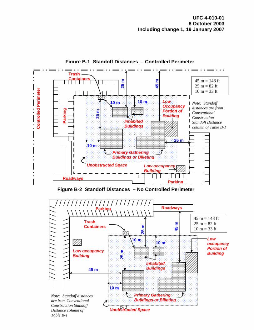
UFC 4-010-01 8 October 2003
Including change 1, 19 January 2007
B-3
Low occupancy Building
Note: Standoff distances are from Conventional Construction Standoff Distance column of Table B-1
Roadways
10 m
Unobstructed Space
Inhabited Buildings
Primary Gathering Buildings or Billeting
45 m
Con
trol
led
Perim
eter
25 m
10 m
25 m
Parking
Park
ing
10 m25
m
Trash Containers
Figure B-1 Standoff Distances – Controlled Perimeter
45 m = 148 ft 25 m = 82 ft 10 m = 33 ft
Low Occupancy Portion of Building
45 m
Low occupancy Portion of Building
Note: Standoff distances are from Conventional Construction Standoff Distance column of Table B-1
Roadways
Low occupancy Building
25 m
Trash Containers
Figure B-2 Standoff Distances – No Controlled Perimeter
Unobstructed Space
10 m
Inhabited Buildings
Primary Gathering Buildings or Billeting
10 m10 m
25m
45 m
Parking
45 m = 148 ft 25 m = 82 ft 10 m = 33 ft

UFC 4-010-01 8 October 2003
Including change 1, 19 January 2007
B-4
Figure B-3 Parking and Roadway Control for Existing Buildings – Controlled Perimeter
Figure B-4 Parking and Roadway Control for Existing Buildings – No Controlled
Perimeter
25 m
10 m
45 m
Existing Primary Gathering Building
Existing Inhabited Building
25 m
25 m
45 m
Roadways
Controlled Parking
No Parking
Parking
45 m = 148 ft 25 m = 82 ft 10 m = 33 ft
Note: Standoff distances are from Conventional Construction Standoff Distance column of Table B-1
25 m10 m
25 m
Roadways
Parking
Existing Primary Gathering Building
Existing Inhabited Building
10 m
10 m
Controlled Parking
No Parking 45 m = 148 ft 25 m = 82 ft 10 m = 33 ft
Note: Standoff distances are from Conventional Construction Standoff Distance column of Table B-1
UFC 4-010-01 8 October 2003
Including change 1, 19 January 2007
B-5
B-1.1.2.1 New Inhabited Buildings. The minimum standoff distance for all new buildings regardless of hardening or analysis is 10 meters (33 feet) for both parking areas and roadways.
B-1.1.2.2 Existing Inhabited Buildings. Where possible, move parking and roadways away from existing inhabited buildings (including leased buildings) in accordance with the standoff distances and explosive weights in Table B-1. It is recognized, however, that moving existing parking areas and roadways or applying structural retrofits may be impractical; therefore, the following operational options are provided for existing inhabited buildings:
B-1.1.2.2.1 Controlled Parking Areas. Controlled parking associated with existing inhabited buildings may be allowed to be as close as 10 meters (33 feet) without hardening or analysis if access control to the parking area is established at the applicable conventional construction standoff distance for parking in Table B-1. In cases where the applicable level of protection can be provided (based on hardening or analysis) with a standoff distance between the conventional construction standoff distance and the minimum standoff distance, parking may be allowed as close as 10 meters (33 feet) if parking is controlled at that lesser applicable standoff distance subject to the following:
B-1.1.2.2.1.1 Parking Within a Controlled Perimeter. The applicable conventional construction or minimum standoff distance at which access will be controlled will be based on the standoff distances for parking and roadways within a controlled perimeter in Table B-1 for the applicable building category.
B-1.1.2.2.1.2 Parking Without a Controlled Perimeter. The applicable conventional construction or minimum standoff distance at which access will be controlled will be based on the standoff distances for parking and roadways without a controlled perimeter in Table B-1 for the applicable building category.
B-1.1.2.2.1.3 Alternate Situations. Controlled parking may be allowed to be closer to existing inhabited buildings where conditions necessitate it and where it can be shown through analysis that the required level of protection can be provided at a lesser standoff distance or if it can be provided through building hardening or other mitigating measures or retrofits. Allowing any parking closer than the distances established in the paragraphs above should be avoided wherever possible, however.
B-1.1.2.2.2 Parking on Existing Roadways. Parking along roadways is subject to the same standoff considerations as other parking. Ensure that there is no parking on roadways within the required standoff distances (conventional construction or minimum in accordance with Table B-1) along existing roads adjacent to existing buildings covered by these standards.
B-1.1.2.2.3 Parking for Family Housing. For high occupancy family housing within a controlled perimeter or where there is access control to the parking area, parking within the required standoff distances may be allowed where designated parking spaces are assigned for specific residents or residences. Do not label assigned parking spaces

UFC 4-010-01 8 October 2003
Including change 1, 19 January 2007
B-6
with names or ranks of the residents, however. Do not encroach upon existing standoff distances where the existing standoff distances are less than the required (conventional construction or minimum in accordance with Table B-1) standoff distances. For example, where existing designated parking is only 8 meters (27 feet) from existing family housing, that parking may be retained, but additional parking will not be allowed closer than 8 meters (27 feet.) B-1.1.3 Parking of Emergency, Command and Operations Support Vehicles. Emergency and command vehicles, as well as operations support vehicles may be parked closer to inhabited buildings than allowed in Table B-1 without hardening or analysis if access to them is continuously controlled or as long as they are never removed from a restricted access area, but they may not be parked closer than the distance associated with unobstructed spaces as established in Standard 2. In addition, where standard operation of buildings includes parking emergency vehicles inside them, such as in fire stations, those emergency vehicles may be parked inside the buildings where necessary as long as access to the building is controlled.
B-1.1.4 Parking of Vehicles Undergoing Maintenance. Vehicles undergoing maintenance may be parked inside maintenance buildings closer to inhabited areas of those buildings than allowed in Table B-1 while they are undergoing repair where operationally necessary.
B-1.1.5 Adjacent Existing Buildings. Where projects for new and existing buildings designed in accordance with these standards include locating parking, roadways, or trash containers near existing inhabited buildings that are not required to meet these standards, the standoff distances from parking, roadways, and trash containers to the buildings that are not required to comply with these standards should comply with the applicable standoff distances in Table B-1. Where those standoff distances are not available, do not allow the parking, roadways, and trash containers to encroach on existing standoff distances to the parking, roadways, and trash containers associated with those existing buildings. For example, if existing parking associated with an existing inhabited building that does not have to comply with these standards is 10 meters from the building, do not allow new parking and roadways associated with a new building closer than 10 meters from the existing building.
B-1.1.6 Parking and Roadway Projects. Where practical, all roadway and parking area projects should comply with the standoff distances from inhabited buildings in Table B-1. Where parking or roadways that are within the standoff distances in Table B-1 from existing buildings are being constructed, expanded, or relocated, do not allow those parking areas and roadways to encroach on the existing standoff distances of any existing inhabited building. That applies even where such projects are not associated with a building renovation, modification, repair, or restoration requiring compliance with these standards.
B-1.1.7 Trash Containers. Measure the standoff distance from the nearest point of the trash container or trash container enclosure to the closest point on the building exterior or inhabited portion of the building. Where the standoff distance is not
UFC 4-010-01 8 October 2003
Including change 1, 19 January 2007
B-7
available, harden trash enclosures to mitigate the direct blast effects and secondary fragment effects of the explosive on the building if the applicable level of protection can be proven by analysis or testing. Alternatively, if trash containers or enclosures are secured to preclude introduction of objects into them by unauthorized personnel, they may be located closer to the building as long as they do not violate the unobstructed space provisions of Standard 2. Openings in screening materials and gaps between the ground and screens or walls making up an enclosure must not be greater than 150 mm (6 inches).
B-1.2 Standard 2. Unobstructed Space. It is assumed that aggressors will not attempt to place explosive devices in areas near buildings where these explosive devices could be visually detected by building occupants observing the area around the building. Therefore, ensure that obstructions within 10 meters (33 feet) of inhabited buildings or portions thereof do not allow for concealment from observation of explosive devices 150 mm (6 inches) or greater in height. This does not preclude the placement of site furnishings or plantings around buildings. It only requires conditions such that any explosive devices placed in that space would be observable by building occupants. For existing buildings where the standoff distances for parking and roadways have been established at less than 10 meters (33 feet) in accordance with paragraph B-1.1.2.2, the unobstructed space may be reduced to be equivalent to that distance.
B-1.2.1 Electrical and Mechanical Equipment. The preferred location of electrical and mechanical equipment such as transformers, air-cooled condensers, and packaged chillers is outside the unobstructed space or on the roof. However this standard does not preclude placement within the unobstructed space as long the equipment provides no opportunity for concealment of explosive devices.
B-1.2.2 Equipment and Trash Container Enclosures. If walls or other screening devices with more than two sides are placed around trash containers or electrical or mechanical equipment within the unobstructed space, enclose the trash containers or equipment on all four sides and the top. Openings in screening materials and gaps between the ground and screens or walls making up an enclosure will not be greater than 150 mm (6 inches). Secure any surfaces of the enclosures that can be opened so that unauthorized personnel cannot gain access through them.
B-1.3 Standard 3. Drive-Up/Drop-Off Areas. Some facilities require access to areas within the required standoff distance for dropping off or picking up people or loading or unloading packages and other objects. Examples that may require drive-up/drop-off include, but are not limited to, medical facilities, exchanges and commissaries, child care centers, and schools.
B-1.3.1 Marking. Where operational or safety considerations require drive-up or drop-off areas or drive-through lanes near buildings, ensure those areas or lanes are clearly defined and marked and that their intended use is clear to prevent parking of vehicles in those areas.
B-1.3.2 Unattended Vehicles. Do not allow unattended vehicles in drive-up or drop-off areas or drive-through lanes.

UFC 4-010-01 8 October 2003
Including change 1, 19 January 2007
B-8
B-1.3.3 Location. Do not allow drive-through lanes or drive-up/drop-off to be located under any inhabited portion of a building.
B-1.4 Standard 4. Access Roads. Where access roads are necessary for the operation of a building (including those required for fire department access), ensure that access control measures are implemented to prohibit unauthorized vehicles from using access roads within the applicable standoff distances in Table B-1.
B-1.5 Standard 5. Parking Beneath Buildings or on Rooftops. Eliminate parking beneath inhabited buildings or on rooftops of inhabited buildings. Where very limited real estate makes such parking unavoidable, the following measures must be incorporated into the design for new buildings or mitigating measures must be incorporated into existing buildings to achieve an equivalent level of protection.
B-1.5.1 Access Control. Ensure that access control measures are implemented to prohibit unauthorized personnel and vehicles from entering parking areas.
B-1.5.2 Structural Elements. Ensure that the floors beneath or roofs above inhabited areas and all other adjacent supporting structural elements will not fail from the detonation in the parking area of an explosive equivalent to explosive weight II in Table B-1.
B-2 STRUCTURAL DESIGN. If the conventional construction standoff distances are achieved, conventional construction should minimize the risk of mass casualties from a terrorist attack. Even if those standoff distances can be achieved, however, incorporate the following additional structural measures into building designs to ensure that buildings do not experience progressive collapse or otherwise experience disproportionate damage.
B-2.1 Standard 6. Progressive Collapse Avoidance. Progressive collapse is considered to be a significant risk for buildings of three or more stories. Basements will be considered stories if they have one or more exposed walls. For all new and existing inhabited DoD buildings of three stories or more, regardless of the standoff distance provided, design the superstructure to sustain local damage with the structural system as a whole remaining stable and not being damaged to an extent disproportionate to the original local damage.
B-2.1.1 Progressive Collapse Avoidance Design Procedures. Competent structural engineers who engage in design work typical or similar to DoD facility design can address the design requirements necessary to reduce the potential of progressive collapse for new and existing facilities required by these standards. For existing and new construction, the progressive collapse avoidance design procedure involves the application of the tie force method and/or alternate path method.
B-2.1.1.1 Tie Force Method. The tie force method is an indirect design method that provides resistance to progressive collapse by enhancing continuity, ductility, and structural redundancy through the design of elements within the structure that tie the members together so they can bridge over damaged areas. The tie force method

UFC 4-010-01 8 October 2003
Including change 1, 19 January 2007
B-9
satisfies the minimum requirements of this standard when only the very low and low levels of protection are required.
B-2.1.1.2 Alternate Path Method. The alternate path method is a direct design method that provides resistance to progressive collapse by demonstrating the structure’s capacity to bridge over missing or deficient elements with only localized damage. The alternate path method is applicable to higher levels of protection, but can be used as an alternative design procedure to satisfy requirements of this standard.
B-2.1.1.3 Other Design Requirements. Other prescriptive design requirements, such as effective column and wall height requirements, and design requirements for upward loads on floors are addressed in UFC 4-023-03, Design of Buildings to Resist Progressive Collapse.
B-2.1.2 Progressive Collapse Avoidance Design Requirements. Follow the design guidance in UFC 4-023-03, Design of Buildings to Resist Progressive Collapse for new and existing DoD Buildings in accordance with the following to reduce the potential for progressive collapse due to localized structural damage due to unforeseeable events.
B-2.1.2.1 Inhabited Buildings. For inhabited buildings, apply the design guidance for at least the very low level of protection in UFC 4-023-03.
B-2.1.2.2 Primary Gathering Buildings, Billeting, and High Occupancy Family Housing. For primary gathering buildings, billeting, and high occupancy family housing, apply the design guidance for at least the low level of protection in UFC 4-023-03.
B-2.2 Standard 7. Structural Isolation.
B-2.2.1 Building Additions. Design all additions to existing buildings to be structurally independent from the adjacent existing building. This will minimize the possibility that collapse of one part of the building will affect the stability of the remainder of the building. Alternatively, verify through analysis that collapse of either the addition or the existing building will not result in collapse of the remainder of the building.
B-2.2.2 Portions of Buildings. Where there are areas of buildings that do not meet the criteria for inhabited buildings, design the superstructures of those areas to be structurally independent from the inhabited area. This will minimize the possibility that collapse of the low occupancy areas of the building will affect the stability of the superstructure of the inhabited portion of the building. Alternatively, verify through analysis that collapse of low occupancy portions of the building will not result in collapse of any portion of the building covered by this standard or design the low occupancy portion of the building to meet the requirements for an inhabited building in accordance with these standards. This standard is not mandatory for existing structures, but it should be implemented where possible
UFC 4-010-01 8 October 2003
Including change 1, 19 January 2007
B-10
B-2.3 Standard 8. Building Overhangs. Avoid building overhangs with inhabited spaces above them where people could gain access to the area underneath the overhang. Where such overhangs must be used, incorporate the following measures into the design for new buildings. Incorporate mitigating measures into existing buildings to achieve an equivalent level of protection.
B-2.3.1 Parking and Roadway Restrictions. Ensure that there are no roadways or parking areas under overhangs. In the case of existing buildings, roadways that cannot be abandoned or relocated may be controlled to ensure vehicles do not park underneath the overhang. B-2.3.2 Floors. Ensure that the floors beneath inhabited areas will not fail from the detonation underneath the overhang of an explosive equivalent to explosive weight II where there is a controlled perimeter and explosive weight I for an uncontrolled perimeter. Explosive weights I and II are identified in Table B-1.
B-2.3.3 Superstructure. The progressive collapse provisions of Standard 6, will include all structural elements within and adjacent to the overhang.
B-2.3.4 Adjacent Building Elements. Ensure that all building elements adjacent to the overhang area provide the appropriate level of protection to explosive weights I and II in Table B-1, as applicable, based on the explosive detonating underneath the overhang.
B-2.4 Standard 9. Exterior Masonry Walls. Unreinforced masonry walls are prohibited for the exterior walls of new buildings. All external masonry walls must have vertical and horizontal reinforcement distributed throughout the wall section. The vertical reinforcement ratio will be at least 0.05%, spaced no more than 1200 mm (4 ft) with reinforcement within 410 mm (1.3 ft) of the ends of walls. The horizontal reinforcement ratio must be at least 0.025%, consisting of either joint reinforcement spaced no more than 410 mm (1.3 ft), or bond beam reinforcement spaced no more than 1200 mm (4 ft), with reinforcement within 410 mm (1.3 ft) of the top and bottom of the wall. For existing buildings, implement mitigating measures to provide an equivalent level of protection.
B-3 ARCHITECTURAL DESIGN. Even where the conventional construction standoff distances are achieved, many aspects of building layout and other architectural design issues must be incorporated into designs to improve overall protection of personnel inside buildings.
B-3.1 Standard 10. Windows and Skylights. To minimize hazards from flying glass fragments from windows and skylights, apply the following provisions for glazing, framing, connections, and supporting structural elements for all new and existing inhabited buildings covered by these standards. These provisions apply even if the conventional construction standoff distances are met or exceeded. These provisions only address minimum standards (very low and low levels of protection.) For higher levels of protection, refer to the DoD Security Engineering Facilities Design Manual.

UFC 4-010-01 8 October 2003
Including change 1, 19 January 2007
B-11
The specific requirements below will result in window and skylight systems that provide for effective hazard mitigation. B-3.1.1 Windows and Skylights with Laminated Glass Glazing. Windows and skylights fabricated using laminated glass glazing will be designed in accordance with the requirements below.
B-3.1.1.1 Glazing. Determine the required thickness of laminated glass and associated polyvinyl-butyral interlayers in single panes and insulating glass unit (IGU) windows using Tables B-2 and B-3, respectively for the applicable level of protection, explosive weight, and standoff distance. Those tables are based on application of ASTM F 2248, Standard Practice for Specifying an Equivalent 3-Second Duration Design Loading for Blast Resistant Glazing Fabricated with Laminated Glass and ASTM E 1300 Standard Practice for Determining Load Resistance of Glass in Buildings., which result in higher levels of protection than those required in these standards as reflected in Table 2-1. The following adjustments to the ASTM standards are made to provide the appropriate performance.
Where the tables indicate “F 2248 / E 1300”, determine the glass thickness using the procedures in ASTM F 2248 and E 1300, respectively based on the applicable charge weight and standoff distance noted in Tables B-2 and B-3.
Do not use less than 6-mm (1/4-in) nominal laminated glass for any single pane exterior windows or skylights. The 6-mm (1/4-in) laminated glass consists of two nominal 3-mm (1/8-in) annealed glass panes bonded together with a minimum of a 0.75-mm (0.030-inch) polyvinyl-butyral (PVB) interlayer. For insulating glass units (IGU), use 6 mm (1/4 inch) laminated glass for the inboard pane as a minimum.
Note that ASTM F2248 can be used for a limited range of charge weights and standoffs, including those covered by this standard. For charge weights and standoffs outside of the range of ASTM F2248 and for glazing alternatives to laminated glass that provide equivalent levels of protection, refer to the DoD Security Engineering Facilities Design Manual.
B-3.1.1.2 Frames. Provide window and skylight frames, mullions and sashes of aluminum or steel. In accordance with ASTM F2248, ensure that the framing members restrict deflections of edges of the blast resistant glazing they support to 1/160 of the length of the supported edge at allowable stress levels under the equivalent 3-second design loading. The equivalent 3-second duration design loading determined using ASTM F 2248 will be based on the applicable explosive weight at the actual standoff distance at which the window is sited, but not greater than the conventional construction standoff distance. In the case of a punched window, the supported edge length will be taken as equal to the span of the glass, regardless of any intermediate support connections. In the case of multi-panel glazing systems, the supported edge length to be considered

UFC 4-010-01 8 October 2003
Including change 1, 19 January 2007
B-12
will be taken as equal to the span of a single glass panel and the deflection will be calculated based on simple support conditions for that length. For existing buildings, complying with this standard may require replacement or significant modification of window and skylight frames, anchorages, and supporting elements. B-3.1.1.3 Glazing Frame Bite. Refer to ASTM F 2248 for glazing frame bite requirements for structurally or non-structurally glazed windows or skylights. For structurally glazed applications, apply the structural silicone bead to both sides of the glass panel for single pane glazing but only to the inboard side for insulating glass units.
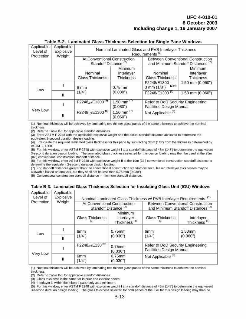
UFC 4-010-01 8 October 2003
Including change 1, 19 January 2007
B-13
Table B-2. Laminated Glass Thickness Selection for Single Pane Windows
Nominal Laminated Glass and PVB Interlayer Thickness Requirements (1)
At Conventional Construction Standoff Distance (2)
Between Conventional Construction and Minimum Standoff Distances (2)
Applicable Level of
Protection
Applicable Explosive
Weight
Nominal Glass Thickness
Minimum Interlayer Thickness
Nominal Glass Thickness
Minimum Interlayer Thickness
I F2248/E1300 – 3 mm (1/8") (3)(4)
1.50 mm (0.060")
Low II
6 mm (1/4")
0.75 mm (0.030") F2248/E1300 (3) 1.50 mm (0.060")
I F224845/E1300 (5) 1.50 mm (7) (0.060")
Refer to DoD Security Engineering Facilities Design Manual
Very Low II
F224810/E1300 (6) 1.50 mm (7) (0.060")
Not Applicable (8)
(1) Nominal thickness will be achieved by laminating two thinner glass panes of the same thickness to achieve the nominal thickness. (2) Refer to Table B-1 for applicable standoff distances. (3) Enter ASTM F 2248 with the applicable explosive weight and the actual standoff distance achieved to determine the equivalent 3-second duration design loading. (4) Calculate the required laminated glass thickness for this pane by subtracting 3mm (1/8") from the thickness determined by ASTM E 1300. (5) For this window, enter ASTM F 2248 with explosive weight I at a standoff distance of 45m (148') to determine the equivalent 3-second duration design loading. The laminated glass thickness selected for this design loading may then be used at the 25m (82') conventional construction standoff distance. (6) For this window, enter ASTM F 2248 with explosive weight II at the 10m (33') conventional construction standoff distance to determine the equivalent 3-second duration design loading. (7) For standoff distances greater than the conventional construction standoff distance, lesser interlayer thicknesses may be allowable based on analysis, but they shall not be less than 0.75 mm (0.030”) (8) Conventional construction standoff distance = minimum standoff distance.
Table B-3. Laminated Glass Thickness Selection for Insulating Glass Unit (IGU) Windows
Nominal Laminated Glass Thickness w/ PVB Interlayer Requirements (1) At Conventional Construction
Standoff Distance (2) Between Conventional Construction and Minimum Standoff Distances (2)
Applicable Level of
Protection
Applicable Explosive
Weight
Glass Thickness (3)
Minimum Interlayer
Thickness (4) Glass Thickness
(3) Interlayer
Thickness (4)
I Low
II
6mm (1/4")
0.75mm (0.030”)
6mm (1/4")
1.50mm (0.060")
I F224845/E130 (5) 0.75mm
(0.030”) Refer to DoD Security Engineering Facilities Design Manual
Very Low II
6mm (1/4")
0.75mm (0.030")
Not Applicable (6)
(1) Nominal thickness will be achieved by laminating two thinner glass panes of the same thickness to achieve the nominal thickness. (2) Refer to Table B-1 for applicable standoff distances. (3) Glass thickness is the same for interior and exterior panes. (4) Interlayer is within the inboard pane only as a minimum. (5) For this window, enter ASTM F 2248 with explosive weight I at a standoff distance of 45m (148') to determine the equivalent 3-second duration design loading. The glass thickness selected for both panes of the IGU for this design loading may then be

UFC 4-010-01 8 October 2003
Including change 1, 19 January 2007
B-14
used at the 25m (82') conventional construction standoff distance. (6) Conventional construction standoff distance = minimum standoff distance.

UFC 4-010-01 8 October 2003
Including change 1, 19 January 2007
B-15
B-3.1.1.4 Connection Design. The design of connections of window and skylight frames to surrounding walls or roofs, of hardware and associated connections, of glazing stop connections, and of other elements in shear will be based upon allowable stress levels. The connection design load will be determined in accordance with ASTM F 2248 based on the applicable explosive weight at the actual standoff distance at which the window is sited, but not greater than the conventional construction standoff distance. Additionally, the allowable fastener loads will be as recommended by the fastener manufacturer for the materials to which the window or skylight systems are being connected. Designers will account for the geometry of the particular frame and the connection configuration being used when calculating bending, shear, bearing, and pull out loads for the connections.
Connections must be capable of preventing the frame from being dislodged from the supporting structural element. This may be demonstrated by calculation as noted above or by testing. If testing is used, the type, number, arrangement, and orientation of the fasteners must be the same in the test as in the fielded application, including eccentricities between the glazing system frame and the line of action of the connections. The structural supporting material used in the test for fastener attachment will be representative of the fielded application. Any deviations in field application of the connections or the connected elements from the test must be demonstrated by calculation to provide equivalent support for the specific application.
B-3.1.2 Supporting Structural Elements. For window and skylight systems, surrounding wall and roof elements and their connections to the rest of the structure may be designed using their nominal strengths. For systems using laminated glass glazing, the design load will be eight times the glazing resistance determined using ASTM E 1300 in conjunction with ASTM F 2248 based on the applicable explosive weight at the actual standoff distance at which the window is sited, but not greater than the conventional construction standoff distance. This design load will be distributed to the structural element only from the tributary area of the window.
Note: The actual connection design load is dictated by the glass type and thickness determined by ASTM E 1300. Therefore, in order to keep the connections loads reasonable, use a glass type and thickness that just exceeds the required glazing resistance.
It is not necessary to account for reactions from the supporting structural elements in the design of the remainder of the structure, because the resulting dynamic loads are likely to be dissipated through multiple mechanisms.
B-3.1.3 Alternate Glazings. Where glazing other than laminated glass is used, design glazing, frames, and connections that will provide the applicable level of protection as described above and in Tables 2-1 and 2-2 for the applicable explosive weight in Table B-1. Refer to the DoD Security Engineering Facilities Design Manual for further guidance. When window or skylight systems use glazing other than laminated
UFC 4-010-01 8 October 2003
Including change 1, 19 January 2007
B-16
glass, the design loads distributed to the frames, the connections, and the supporting structural elements will be based on the ultimate resistance of the glazing being used.
B-3.1.4 Alternate Method of Analysis. As an alternative to the design approach described above, any or all of the glazing, framing members, connections, and supporting structural elements may be designed using dynamic analysis to prove the window system will provide performance equivalent to or better than the hazard rating associated with the applicable level of protection as indicated in Table 2-1. The design loading for a dynamic analysis will be the appropriate pressure and impulse from the applicable explosive weight at the actual standoff distance at which the window is sited, but not greater than the conventional construction standoff distance. The design loading will be applied over the areas tributary to the element being analyzed.
B-3.1.5 Testing. As an alternative to the provisions of this standard, window and skylight systems may be dynamically tested to demonstrate performance equivalent to or better than the hazard rating associated with the applicable level of protection as indicated in Table 2-1. Testing will include the entire window or skylight system, including connections, and will be in accordance with ASTM F 1642. If standoff distances greater than conventional construction standoff distances are provided, the standoff distances on which the analysis and testing are based will not exceed the conventional construction standoff distance.
B-3.1.6 Window and Skylight Replacement Projects. Whenever window and skylight glazing is being replaced in existing inhabited buildings as part of a planned window or glazing replacement project, whether or not the building meets the triggers in paragraph 1-6.2, install glazing and frames that meet all of the requirements above.
B-3.1.7 Alternative Window Treatments. Window retrofit products that rely on fragment retention film, fragment retention film as part of a retrofit system, or blast curtain systems generally have higher life cycle costs than laminated glass windows due to their shorter design lives and due to operation and maintenance issues. Application of those products, therefore, will be governed by the following paragraphs:
B-3.1.7.1 New Buildings and Existing Buildings Undergoing Major Renovations or Window Replacement Projects. Window retrofits incorporating fragment retention film or blast curtains will not be considered an acceptable alternative for new inhabited buildings or for existing inhabited buildings that are required to comply with these standards, except for leased buildings as stated below.
B-3.1.7.2 Leased Buildings. For inhabited leased buildings that are required to comply with these standards, windows using laminated glass are preferred, but window retrofits incorporating fragment retention film or blast curtains may be allowed if they provide an equivalent level of protection to the laminated glass windows as long as the lease agreement stipulates that they will be maintained and replaced in accordance with manufacturers’ recommendations. This will include meeting the requirements for supporting structural elements. Compliance with the required level of protection may be demonstrated through analysis or through testing. Testing will be performed in accordance with ASTM F1642.

UFC 4-010-01 8 October 2003
Including change 1, 19 January 2007
B-17
B-3.1.7.3 Other Existing Buildings. For existing buildings that are not required to comply with these standards, window retrofits incorporating fragment retention film or blast curtains are considered to be viable and economical solutions to mitigating the effects of explosive attacks, but should be evaluated prior to installation so that reduction in glass hazards may be determined.
B-3.2 Standard 11. Building Entrance Layout. The areas outside of installations are commonly not under the direct control of the installations. Where the main entrances to buildings face installation perimeters, people entering and exiting the buildings are vulnerable to being fired upon from vantage points outside the installations. To mitigate those vulnerabilities apply the following measures:
B-3.2.1 New Buildings. For new inhabited buildings, ensure that the main entrance to the building does not face an installation perimeter or other uncontrolled vantage points with direct lines of sight to the entrance or provide means to block the lines of sight.
B-3.2.2 Existing Buildings. For existing inhabited buildings where the main entrance faces an installation perimeter, either use a different entrance as the main entrance or screen that entrance to limit the ability of potential aggressors to target people entering and leaving the building.
B-3.3 Standard 12. Exterior Doors. For all new and existing buildings covered by these standards where the conventional construction standoff distance is met or exceeded, ensure that all exterior doors into inhabited areas open outwards. By doing so, the doors will seat into the door frames in response to an explosive blast, increasing the likelihood that the doors will not enter the buildings as hazardous debris. Where the standoff distance available is less then the conventional construction standoff distance, design the doors to achieve the applicable performance in Table 2-1.
B-3.3.1 Glazed Doors. In addition to the provisions above, glazing in glazed doors must meet the glazing and frame bite provisions of Standard 10.
B-3.3.2 Alternative Designs. As an alternative to the above provisions for all doors, position doors such that they will not be propelled into rooms if they fail in response to a blast or provide other means to ensure they do not become hazards to building occupants. The glazing in glazed doors must still meet the provisions above if this alternative is exercised.
B-3.4 Standard 13. Mail Rooms. The following measures address the location of rooms to which mail is delivered or in which mail is handled in new and existing inhabited buildings. These standards need not be applied to mail rooms to which mail is delivered that was initially delivered to a central mail handling facility. These standards should be applied to such mail rooms where possible, however, to account for potential changes in mail handling procedures over the life of the building. The measures involve limiting collateral damage and injuries and facilitating future upgrades to enhance protection should they become necessary.

UFC 4-010-01 8 October 2003
Including change 1, 19 January 2007
B-18
B-3.4.1 Location. Where a new or existing building covered by these standards must have a mail room, locate that mail room on the perimeter of the building. By locating the mail room on the building perimeter there is an opportunity to modify it in the future if a mail bomb threat is identified. Where mail rooms are located in the interior of buildings, few retrofit options are available for mitigating the mail bomb threat.
B-3.4.2 Proximity. Locate mail rooms as far from heavily populated areas of the building and critical infrastructure as possible. This measure will minimize injuries and damage if a mail bomb detonates in the mail room. Further, it will reduce the potential for wider dissemination of hazardous agents. These apply where the mail room is not specifically designed to resist those threats. B-3.4.3 Sealing. To limit migration into buildings of airborne chemical, biological, and radiological agents introduced into mail rooms, ensure that mail rooms are well sealed between their envelopes and other portions of the buildings in which they are located. Ensure the mail room walls are of full height construction that fully extends and is sealed to the undersides of the roofs, to the undersides of any floors above them, or to hard ceilings (i.e. gypsum wallboard ceiling.) Sealing should include visible cracks, the interface joints between walls and ceilings/roofs, and all wall and ceiling/roof penetrations. Doors will have weather stripping on all four edges. Refer to the DoD Security Engineering Facilities Design Manual for additional guidance. B-3.5 Standard 14. Roof Access. For all new and existing inhabited buildings covered by these standards, control access to roofs to minimize the possibility of aggressors placing explosives or chemical, biological, or radiological agents there or otherwise threatening building occupants or critical infrastructure.
B-3.5.1 New Buildings. For new buildings eliminate all external roof access by providing access from internal stairways or ladders, such as in mechanical rooms.
B-3.5.2 Existing Buildings. For existing buildings, eliminate external access where possible or secure external ladders or stairways with locked cages or similar mechanisms.
B-3.6 Standard 15. Overhead Mounted Architectural Features. For all new and existing buildings covered by these standards, ensure that overhead mounted features weighing 14 kilograms (31 pounds) or more (excluding distributed systems such as suspended ceilings that collectively exceed that weight) are mounted to minimize the likelihood that they will fall and injure building occupants. Mount all such systems so that they resist forces of 0.5 times the component weight in any horizontal direction and 1.5 times the component weight in the downward direction. This standard does not preclude the need to design architectural feature mountings for forces required by other criteria such as seismic standards.
B-4 ELECTRICAL AND MECHANICAL DESIGN. Electrical and mechanical design standards address limiting damage to critical infrastructure, protecting building

UFC 4-010-01 8 October 2003
Including change 1, 19 January 2007
B-19
occupants against chemical, biological, and radiological threats, and notifying building occupants of threats or hazards.
B-4.1 Standard 16. Air Intakes. Air intakes to heating, ventilation, and air conditioning (HVAC) systems that are designed to move air throughout a building that are at ground level provide an opportunity for aggressors to easily place contaminants where they could be drawn into the building. The following measures will be applied to minimize those opportunities.
B-4.1.1 New Buildings. For all new inhabited buildings covered by this UFC locate all outside air intakes that distribute air throughout the building at least 3 meters (10 feet) above the ground.
B-4.1.2 Existing Buildings. The above requirement is recommended, but not mandatory, for existing inhabited buildings covered by these standards.
B-4.2 Standard 17. Mail Room Ventilation. To ensure airborne chemical, biological, and radiological agents introduced into mail rooms do not migrate into other areas of buildings in which the mail rooms are located, provide separate, dedicated air ventilation systems for mail rooms. Refer to the DoD Security Engineering Facilities Design Manual for additional guidance. B-4.2.1 Other Heating and Cooling Systems. Building heating and cooling systems such as steam, hot water, chilled water, and refrigerant may serve mail rooms as long as the airflow systems for the mail rooms and other areas of the buildings in which they are located remain separate. B-4.2.2 Dedicated Exhaust Systems. Provide dedicated exhaust systems within mail rooms to maintain slight negative air pressures with respect to the remainder of the buildings in which the mail rooms are located so that the flow of air is into and contained in the mail rooms. Though the airflow into the mail rooms will not eliminate the potential spread of contamination by personnel leaving the mail room, it will limit the migration of airborne contaminants through openings and open doorways. B-4.2.3 Outside Intakes, Relief, and Exhausts. Provide mail room ventilation system outside air intakes, relief air, and exhausts with low leakage isolation dampers that can be automatically closed to isolate the mail rooms. The low leakage dampers will have maximum leakage rates of 3 cfm/square foot with a differential pressure of one inch of water gage across the damper. B-4.2.4 Isolation Controls. Provide separate switches or methods of control to isolate mail rooms in the event of a suspected or actual chemical, biological, or radiological release. B-4.3 Standard 18. Emergency Air Distribution Shutoff. For all new and existing inhabited buildings, provide an emergency shutoff switch in the HVAC control system that can immediately shut down the air distribution system throughout the
UFC 4-010-01 8 October 2003
Including change 1, 19 January 2007
B-20
building except where interior pressure and airflow control would more efficiently prevent the spread of airborne contaminants and/or ensure the safety of egress pathways. Locate the switch (or switches) to be easily accessible by building occupants. Providing such a capability will allow the facility manager or building security manager to limit the distribution of airborne contaminants that may be introduced into the building. B-4.3.1 Outside Air Intakes and Exhausts. Provide all outside air intakes, relief air, and exhaust openings with low leakage dampers that are automatically closed when the emergency air distribution shutoff switch is activated. The low leakage dampers will have maximum leakage rates of 3 cfm/square foot with a differential pressure of one inch of water gage across the damper. B-4.3.2 Critical Areas. Local air handing units serving critical areas where cooling and/or heating must be maintained to prevent mission failure, loss of data or unsafe conditions can continue to recirculate air, but outside air, relief air and exhaust must be closed with low leakage isolation dampers. B-4.4 Standard 19. Utility Distribution and Installation. Utility systems can suffer significant damage when subjected to the shock of an explosion. Some of these utilities may be critical for safely evacuating personnel from the building or their destruction could cause damage that is disproportionate to other building damage resulting from an explosion. To minimize the possibility of the above hazards, apply the following measures:
B-4.4.1 Utility Routing. For all new inhabited buildings, route critical or fragile utilities so that they are not on exterior walls or on walls shared with mail rooms. This requirement is recommended, but not mandatory, for existing buildings.
B-4.4.2 Redundant Utilities. Where redundant utilities are required in accordance with other requirements or criteria, ensure that the redundant utilities are not collocated or do not run in the same chases. This minimizes the possibility that both sets of utilities will be adversely affected by a single event.
B-4.4.3 Emergency Backup Systems. Where emergency backup systems are required in accordance with other requirements or criteria, ensure that they are located away from the system components for which they provide backup. This minimizes the possibility that both the primary system and its backup will be adversely affected by a single event.
B-4.5 Standard 20. Equipment Bracing. Mount all overhead utilities and other fixtures weighing 14 kilograms (31 pounds) or more (excluding distributed systems such as piping networks that collectively exceed that weight) to minimize the likelihood that they will fall and injure building occupants. Design all equipment mountings to resist forces of 0.5 times the equipment weight in any horizontal direction and 1.5 times the equipment weight in the downward direction. This standard does not preclude the need

UFC 4-010-01 8 October 2003
Including change 1, 19 January 2007
B-21
to design equipment mountings for forces required by other criteria such as seismic standards.
B-4.6 Standard 21. Under Building Access. To limit opportunities for aggressors placing explosives underneath buildings, ensure that access to crawl spaces, utility tunnels, and other means of under building access is controlled.
B-4.7 Standard 22. Mass Notification. All inhabited buildings must have a timely means to notify occupants of threats and instruct them what to do in response to those threats. To achieve that goal, provide the following:
B-4.7.1 New Buildings. All new inhabited buildings must have a capability to provide real-time information to building occupants or personnel in the immediate vicinity of the building during emergency situations. The information relayed must be specific enough to determine the appropriate response actions. Any system, procedure, or combination thereof that provides this capability will be acceptable under this standard. Refer to UFC 4-021-01 for further guidance.
B-4.7.2 Existing Buildings. For existing buildings, the above requirement is mandatory for primary gathering buildings, billeting, and high occupancy family housing, but recommended for all inhabited buildings.

UFC 4-010-01 8 October 2003
Including change 1, 19 January 2007
B-22
This Page Intentionally Left Blank
UFC 4-010-01 8 October 2003
Including change 1, 19 January 2007
C-1
APPENDIX C
RECOMMENDED ADDITIONAL ANTITERRORISM MEASURES FOR NEW AND EXISTING BUILDINGS
C-1 SITE PLANNING. The following additional measures, if implemented, will significantly enhance site security with little increase in cost and should be considered for all new and existing inhabited buildings.
C-1.1 Recommendation 1. Vehicle Access Points. The first line of defense in limiting opportunities for aggressors to get vehicles close to DoD buildings is at vehicle access points at the controlled perimeter, in parking areas, and at drive-up/drop-off points. Keep the number of access points to the minimum necessary for operational or life safety purposes. This will limit the number of points at which access may have to be controlled with barriers and/or personnel at increased Force Protection Conditions or if the threat increases in the future.
C-1.2 Recommendation 2. High-Speed Vehicle Approaches. The energy of a moving vehicle increases with the square of its velocity; therefore, minimizing a vehicle’s speed allows vehicle barriers to be lighter and less expensive should vehicle barriers ever become necessary. To facilitate reductions in vehicle speeds in the future, ensure there are no unobstructed vehicle approaches perpendicular to inhabited buildings at the required parking and roadway standoff distances.
C-1.3 Recommendation 3. Vantage Points. Vantage points are natural or man-made positions from which potential aggressors can observe and target people or other assets in and around buildings. Identify vantage points outside the control of personnel in targeted buildings and either eliminate them or provide means to avoid exposure to them. Means to avoid exposure may include actions such as reorienting buildings or shielding people or assets in and around them using such measures as reflective glazing, walls, privacy fencing, or vegetation.
C-1.4 Recommendation 4. Drive-Up/Drop Off Areas. Locate these areas away from large glazed areas of buildings to minimize the potential for hazardous flying glass fragments in the event of an explosion. For example, locate the lane at outside corners of buildings or otherwise away from main entrances. Coordinate the drive-up/drop-off points with building geometries to minimize the possibility that explosive blast forces could be increased due to being trapped or otherwise concentrated. For further discussion of this issue, refer to the DoD Security Engineering Facilities Design Manual.
C-1.5 Recommendation 5. Building Location. Activities with large visitor populations provide opportunities for potential aggressors to get near buildings with minimal controls, and therefore, limit opportunities for early detection. To limit those opportunities, maximize separation distance between inhabited buildings and areas with large visitor populations.
UFC 4-010-01 8 October 2003
Including change 1, 19 January 2007
C-2
C-1.6 Recommendation 6. Railroad Location. Avoid sites for inhabited buildings that are close to railroads. Where railroads are in the vicinity of existing buildings, provide standoff distances between the railroad and any inhabited buildings based on the standoff distances and explosive weight associated with controlled perimeters in Table B-1. Where those standoff distances are not available, and since moving existing railroads may be difficult and prohibitively expensive, ensure that there are procedures in place to prohibit trains from stopping in the vicinity of inhabited buildings.
C-1.7 Recommendation 7. Access Control for Family Housing. For new family housing areas, provide space for controlling access at the perimeter of the housing area so that a controlled perimeter can be established there if the need arises in the future.
C-1.8 Recommendation 8. Standoff for Family Housing. For new family housing construction, maintain a standoff distance of 25 meters (82 feet) from installation perimeters and roads, streets, or highways external to housing areas.
C-1.9 Recommendation 9. Minimize Secondary Debris. To reduce the hazard of flying debris in the event of an explosion, eliminate unrevetted barriers and site furnishings in the vicinity of inhabited structures that are accessible to vehicle traffic. Revet exposed barriers and site furnishings near inhabited buildings with a minimum of 1 meter (3 feet) of soil or equivalent alternative techniques to prevent fragmentation hazards associated with destruction of the barriers in the event of an explosion.
C-1.10 Recommendation 10. Building Separation. This recommendation applies to new buildings and is established to minimize the possibility that an attack on one building causes injuries or fatalities in adjacent buildings. The separation distance is predicated on the potential use of indirect fire weapons such as those containing explosives equivalent to explosive weight III in Table D-1.
C-1.10.1 Primary Gathering Buildings, Billeting, and High Occupancy Family Housing. For all new billeting, high occupancy family housing, and primary gathering buildings, ensure that all adjacent inhabited buildings are separated from those buildings by at least 10 meters. Where it is necessary to encroach on those building separations, analyze the buildings and provide hardened building components as necessary to mitigate the effects of the indirect fire weapons equivalent to those identified as explosive weight III in Table D-1 to the low level of protection. Levels of protection are described in Table 2-1 and in UFC 4-020-01. The indirect fire weapon should be assumed to detonate at a distance from the target building of one-half of the separation distance.
C-1.10.2 Other Inhabited Buildings. There are no minimum separation distances recommended for antiterrorism purposes for inhabited buildings other than billeting, high occupancy family housing, and primary gathering buildings.
C-2 STRUCTURAL AND ARCHITECTURAL DESIGN. The following additional measures, if implemented, will significantly enhance building occupants’

UFC 4-010-01 8 October 2003
Including change 1, 19 January 2007
C-3
safety and security with little increase in cost. Consider these measures for all new and existing inhabited buildings.
C-2.1 Recommendation 11. Structural Redundancy. Unexpected terrorist acts can result in local collapse of building structural components. To limit the extent of collapse of adjacent components, utilize highly redundant structural systems such as moment resisting frames, detail connections to provide continuity across joints equal to the full structural capacity of connected members, and detail members to accommodate large displacements without complete loss of strength. This recommendation is consistent with paragraph B-2.1 (Standard6) for preventing progressive collapse, but recommends selection of certain structural systems and greater attention to structural details.
C-2.2 Recommendation 12. Internal Circulation. Design circulation within buildings to facilitate visual detection and monitoring of unauthorized personnel approaching controlled areas or occupied spaces.
C-2.3 Recommendation 13. Visitor Control. Controlling visitor access maximizes the possibility of detecting potential threatening activities. Keep locations in buildings where visitor access is controlled away from sensitive or critical areas, areas where high-risk or mission-critical personnel are located, or other areas with large population densities of DoD personnel.
C-2.4 Recommendation 14. Asset Location. To minimize exposure to direct blast effects and potential impacts from hazardous glass fragments and other potential debris, locate critical assets and mission-critical or high-risk personnel away from the building exterior.
C-2.5 Recommendation 15. Room Layout. In rooms adjacent to the exterior of the building, position personnel and critical equipment to minimize exposure to direct blast effects and potential impacts from hazardous glass fragments and other potential debris.
C-2.6 Recommendation 16. External Hallways. Since doors can become hazardous debris during explosive blast events, doors designed to resist blast effects are expensive, and because external hallways have large numbers of doors leading into inhabited areas, avoid exterior hallway configurations for inhabited structures.
C-2.7 Recommendation 17. Windows. To minimize the potential for glazing hazards, minimize the size and number of windows for new construction.

UFC 4-010-01 8 October 2003
Including change 1, 19 January 2007
C-4
This Page Intentionally Left Blank
UFC 4-010-01 8 October 2003
Including change 1, 19 January 2007
D-1
APPENDIX D
DOD MINIMUM ANTITERRORISM STANDARDS FOR EXPEDITIONARY AND TEMPORARY STRUCTURES
D-1 SITE PLANNING STANDARDS. All the standards that are unique to expeditionary and temporary structures pertain to site planning. Integrate operational, logistic, and security requirements into the overall configuration of structures, equipment, landscaping, parking, roads, and other features. The most cost-effective solution for mitigating explosive effects on expeditionary and temporary structures is to keep explosives as far away as possible. This is especially critical for these types of structures because hardening may or may not be possible. Dispersed layouts reduce risks from a variety of threats by taking full advantage of terrain and site conditions; therefore, nothing in these standards is intended to discourage dispersal. Costs and requirements for expeditionary and temporary structure hardening are addressed in UFC 4-020-01.
D-1.1 Standard 1. Standoff Distances. The standoff distances apply to all new and existing DoD expeditionary and temporary structures covered by these standards except as otherwise stated below. The standoff distances are presented in Table D-1and illustrated in Figure D-1. Except as otherwise required in these standards, where the standoff distances in Table D-1 can be provided, use conventional expeditionary and temporary structures without a specific analysis of blast effects.
Where those distances are not available, analysis of the structure by an engineer experienced in blast-resistant design is required and hardening will be applied as necessary (in those cases which permit structure hardening) to mitigate the effects of the explosives indicated in Table D-1 at the achievable standoff distance to the appropriate level of protection.
The appropriate levels of protection for each structure category are shown in Table D-1, and are described in Table 2-2 and in UFC 4-020-01. Note that container structures and pre-engineered buildings respond similarly to other buildings, so they are separated from the other expeditionary and temporary structures below. Of the remaining expeditionary and temporary structure types, the two structure types in Table D-1 respond in fundamentally different ways to explosive effects. Standoff distances in Table D-1 reflect those differences.
D-1.1.1 Controlled Perimeter. Measure the standoff distance from the closest point on the structure exterior to the controlled perimeter.
D-1.1.1.1 Container Structures and Pre-engineered Buildings. For these structures, apply the guidance for new and existing buildings in Appendix B.
D-1.1.1.2 Fabric Covered and other Expeditionary or Temporary Structures. Provide the standoff distance from Table D-1 for the applicable structure category.

UFC 4-010-01 8 October 2003
Including change 1, 19 January 2007
D-2
D-1.1.2 Parking and Roadways. Standoff distances for parking and roadways are based on the assumption that there is a controlled perimeter at which larger vehicle bombs will be detected and kept from entering the controlled perimeter. Where there is a controlled perimeter, the standoff distances and explosive weight associated with parking and roadways in Table D-1 apply unless otherwise stated below. If there is no controlled perimeter, assume that the larger explosive weights upon which the controlled perimeter standoff distances are based (explosive weight I from Table D-1) can access parking and roadways near structures. Therefore, where there is no controlled perimeter, use standoff distances from parking and roadways according to the distances and the explosive weight associated with controlled perimeters in Table D-1.
D-1.1.2.1 Container Structures and Pre-engineered Buildings. For these structures, apply the guidance for new and existing buildings in Appendix B.
D-1.1.2.2 Fabric Covered and other Expeditionary or Temporary Structures. Measure the standoff distance from the closest point on the structure exterior to the closest edge of parking areas and roadways. The minimum standoff for all structures regardless of hardening or analysis is 10 meters (33 feet).
D-1.1.2.3 Existing Fabric Covered and other Expeditionary or Temporary Structures. Moving existing parking areas and roadways may be difficult to achieve and structural retrofits to existing structures may be prohibitively expensive or technically impossible; therefore, the following operational options are provided for existing inhabited structures where the standoff distances in Table D-1 are impractical to achieve.
D-1.1.2.3.1 Parking Areas. Establish access control to portions of parking areas to ensure unauthorized vehicles are not allowed closer than the required standoff distance. For primary gathering structures and billeting, if access control is provided to prevent unauthorized parking within the required standoff distance, controlled parking may be permitted as close as 10 meters (33 feet) without hardening or analysis.
D-1.1.2.3.2 Roadways. Eliminate parking within the required standoff distance along roads adjacent to existing structures covered by these standards.
D-1.1.3 Trash Containers. Measure the standoff distance from the nearest point of the trash container or trash container enclosure to the closest point on the structure exterior. Where the standoff distance is not available, hardening of trash enclosures to mitigate the direct blast effects and secondary fragment effects of the explosive on the structure is acceptable, if the applicable level of protection can be proven by analysis or testing. If trash enclosures are secured to preclude introduction of objects into the enclosures by unauthorized personnel, they may be located closer to the structure as long as they do not violate the unobstructed space provisions of Standard 3 below. Openings in screening materials and gaps between the ground and screens or walls making up an enclosure will not be greater than 150 mm (6 inches).
UFC 4-010-01 8 October 2003
Including change 1, 19 January 2007
D-3
D-1.1.3.1 Container Structures and Pre-engineered Buildings. For these structures, apply the guidance for new and existing buildings in Appendix B.
D-1.1.3.2 Fabric Covered and other Expeditionary or Temporary Structures. Provide the standoff distance from Table D-1 for the applicable structure category.
D-1.2 Standard 2. Structure Separation. Structure separation requirements are established to minimize the possibility that an attack on one structure causes injuries or fatalities in adjacent structures. The separation distance is predicated on the potential use of indirect fire weapons.
D-1.2.1 Billeting and Primary Gathering Structures.
D-1.2.1.1 Container Structures and Pre-engineered Buildings. For these structures, ensure that adjacent inhabited structures are separated by at least 10 meters. Where it is necessary to encroach on that separation distance, analyze the structure and harden structure components as necessary to mitigate the effects of the explosive indicated in Table D-1 to the appropriate level of protection shown in Table B-1. Levels of protection are described in Table 2-1 and in UFC 4-020-01.
D-1.2.1.2 Fabric Covered and other Expeditionary or Temporary Structures. For all new billeting and primary gathering structures, ensure that adjacent structures are separated by at least the distances in Table D-1. Where it is necessary to encroach on those structure separations, analyze the structure and provide hardened structure components as necessary to mitigate the effects of the explosive indicated in Table D-1 to the appropriate level of protection as shown in Table D-1. Levels of protection are described in Table 2-2 and in UFC 4-020-01.
D-1.2.2 Other Inhabited Structures. There are no minimum separation distances required for antiterrorism for inhabited structures other than billeting and primary gathering structures.
D-1.3 Standard 3. Unobstructed Space. Keep areas within 10 meters (33 feet) of all expeditionary and temporary structures free of items other than those that are part of the utilities and other supporting infrastructure.
D-2 ADDITIONAL STANDARDS. In addition to the specific standards detailed in this appendix, apply the standards from Appendix B to expeditionary and temporary structures as follows:
D-2.1 Container Structures and Pre-engineered Buildings. For these structures, all standards in Appendix B apply.
D-2.2 Fabric Covered and other Expeditionary or Temporary Structures. Apply the following standards from Appendix B to these structures:
D-2.2.1 Standard 3. Drive-Up/Drop Off Areas.
D-2.2.2 Standard 4. Access Roads.

UFC 4-010-01 8 October 2003
Including change 1, 19 January 2007
D-4
D-2.2.3 Standard 10. Windows and Skylights.
D-2.2.4 Standard 11. Building Entrance Layout.
D-2.2.5 Standard 20. Equipment Bracing.
D-2.2.6 Standard 22. Mass Notification.
D-3 ANTITERRORISM RECOMMENDATIONS. Apply all recommendations except for Recommendation 7 (Access control for family housing) and Recommendation 8 (Standoff for family housing) from Appendix C to all expeditionary and temporary structures.

UFC 4-010-01 8 October 2003
Including change 1, 19 January 2007
D-5
Table D-1 Standoff Distances and Separation for Expeditionary and Temporary Structures
Standoff Distance or Separation Requirements Location Structure Category Applicable
Level of Protection
Fabric Covered
Structures(1)
Other Expeditionary
and Temporary
Structures(1)(2)
Applicable Explosive
Weight (TNT)
(3)
Billeting Low 31 m (102 ft.)
71 m (233 ft.)
I
Primary Gathering Structure Low 31 m
(102 ft.) 71 m (233 ft.)
I
Controlled Perimeter
or Parking and Roadways without a
Controlled Perimeter Inhabited Structure Very Low 24 m
(79 ft.) 47 m (154 ft.)
I
Billeting Low 14 m (46 ft.)
32 m (105 ft.)
II
Primary Gathering Structure Low 14 m
(46 ft.) 32 m (105 ft.)
II
Parking and Roadways
within a Controlled Perimeter
Inhabited Structure Very Low 10 m (33 ft.)
23 m (75 ft.)
II
Billeting Low 14 m (46 ft.)
32 m (105 ft.)
II
Primary Gathering Structure Low 14 m
(46 ft.) 32 m (105 ft.)
II
Trash
Containers
Inhabited Structure Very Low 10 m (33 ft.)
23 m (75 ft.)
II
Separation between Structure Groups
Low 18 m (59 ft.)
18 m (59 ft.)
III(5)
Separation between Structure Rows
Low 9 m (30 ft.)
9 m (30 ft.)
III (5)
Structure
Separation(4)
Separation between Structures in a Row
Very Low 3.5 m (12 ft.)
3.5 m (12 ft.)
III(5)
(1) See Definitions for a complete description of these structure types. (2) For container structures, Appendix B applies.
(3) See UFC 4-010-02, for the specific explosive weights (kg/pounds of TNT) associated with designations – I, II, III. UFC 4-010-02 is For Official Use Only (FOUO) (4) Applies to Billeting and Primary Gathering Structures only. No minimum separation distances for other inhabited structures.
(5) Explosive for building separation is an indirect fire (mortar) round at a standoff distance of half the separation distance.
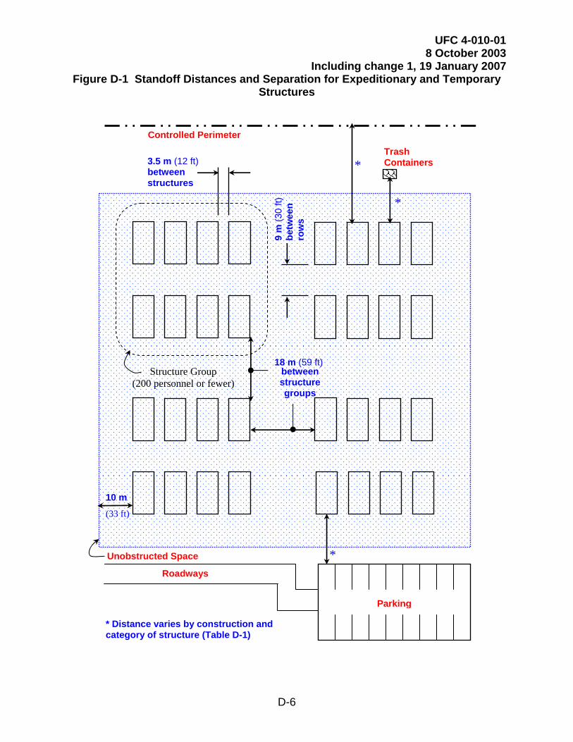
UFC 4-010-01 8 October 2003
Including change 1, 19 January 2007
D-6
Figure D-1 Standoff Distances and Separation for Expeditionary and Temporary Structures
3.5 m (12 ft) between structures
9 m
(30
ft)
betw
een
row
s
18 m (59 ft) between structure groups
Unobstructed Space
10 m
(33 ft)
Trash Containers
Controlled Perimeter
*
*
Roadways
Parking
*
* Distance varies by construction and category of structure (Table D-1)
Structure Group (200 personnel or fewer)

UFC 4-010-01 8 October 2003
Including change 1, 19 January 2007
D-7
This Page Intentionally Left Blank