doe f 241.3 (2-01) p.1 of 2 united states department...
TRANSCRIPT

DOE F 241.3 (2-01) p.1 of 2 UNITED STATES DEPARTMENT OF ENERGY (DOE) OMB CONTROL NO.
Announcement of Scientific and Technical Information (STI) 1910-1400
(For Use By Financial Assistance Recipients and Non-M&O/M&I Contractors) PART I: STI PRODUCT DESCRIPTION
(To be completed by Recipient/Contractor)
A. STI Product Identifiers 1. REPORT/PRODUCT NUMBER(s) None 2. DOE AWARD/CONTRACT NUMBER(s) DE-FC36-97ID13554 3. OTHER IDENTIFYING NUMBER(s) None B. Recipient/Contractor University of Utah, 135 S 1460 E, Salt Lake City, UT C. STI Product Title Suspension Hydrogen Reduction of Iron Oxide Concentrates D. Author(s) H. Y. Sohn E-mail Address(es): [email protected] E. STI Product Issue Date/Date of Publication
F. STI Product Type (Select only one) X 1. TECHNICAL REPORT X Final Other (specify)
2. CONFERENCE PAPER/PROCEEDINGS Conference Information (title, location, dates)
3. JOURNAL ARTICLE
a. TYPE: Announcement Citation Only Preprint Postprint b. JOURNAL NAME c. VOLUME d. ISSUE e. SERIAL IDENTIFIER (e.g. ISSN or CODEN)
4. OTHER, SPECIFY G. STI Product Reporting Period Thru
H. Sponsoring DOE Program Office Office of Industrial Technologies (OIT)(EE20) I. Subject Categories (list primary one first) 32 Energy Conservation, Consumption and Utilization Keywords: Ironmaking, Iron Oxide, Suspension Reduction J. Description/Abstract The objective of this project is to develop a new ironmaking technology based on hydrogen and fine iron oxide concentrates in a suspension reduction process. The ultimate objective of the new technology is to replace the blast furnace and to drastically reduce CO2 emissions in the steel industry. The goals of this phase of development are: the performance of detailed material and energy balances, thermochemical and equilibrium calculations for sulfur and phosphorus impurities, the determination of the complete kinetics of hydrogen reduction and bench-scale testing of the suspension reduction process using a large laboratory flash reactor. K. Intellectual Property/Distribution Limitations (must select at least one; if uncertain contact your Contracting Officer (CO)) X 1. UNLIMITED ANNOUNCEMENT (available to U.S. and non-U.S. public; the Government assumes no liability for disclosure of such data)
2. COPYRIGHTED MATERIAL: Are there any restrictions based on copyright? Yes No. If yes, list the restrictions as contained in your award document
3. PATENTABLE MATERIAL: THERE IS PATENTABLE
MATERIAL IN THE DOCUMENT. INENTION DISCLOSURE SUBMITTED TO DOE: DOE Docket Number: S- (Sections are marked as restricted distribution pursuant to 35 USC 205)
4. PROTECTED DATA: CRADA Other, specify Release date (required) no more than 5 years from date listed in Part I.E. above
5. SMALL BUSINESS INNOVATION RESEARCH (SBIR) DATA Release date (required) no more than 4 years from date listed in Part I.E. above
6. SMALL BUSINESS TECHNOLOGY TRANSFER RESEARCH (STTR) DATA Release date (required) no more than 4 years from date listed in Part I.E. above
7. OFFICE OF NUCLEAR ENERGY APPLICED TECHNOLOGY L. Recipient/Contract Point of Contact Contact for additional information (contact or organization name To be included in published citations and who would Receive any external questions about the content of the STI Product or the research contained herein) Dr. H.Y. Sohn Name and/or Position [email protected] (801)581-5491 E-mail Phone Dept. of Metallurgical Engineering, University of Utah, Salt Lake City, UT
M M D D Y Y Y Y
M M D D Y Y Y Y
M M D D Y Y Y Y
12 31 2007 M M D D Y Y Y Y
02 23 2005 M M D D Y Y Y Y
03 31 2008 M M D D Y Y Y Y

DOE F 241.3 (2-01) p.2 of 2 UNITED STATES DEPARTMENT OF ENERGY (DOE) OMB CONTROL NO.
Announcement of Scientific and Technical Information (STI) 1910-1400
(For Use By Financial Assistance Recipients and Non-M&O/M&I Contractors)
PART II: STI PRODUCT MEDIA/FORMAT and LOCATION/TRANSMISSION
(To be completed by Recipient/Contractor)
A. Media/Format Information: 1. MEDIUM OF STI PRODUCT IS: X Electronic Document Computer Medium Audiovisual Material Paper No Full-text 2. SIZE OF STI PRODUCT 59 Pages, 1248 KB 3. SPECIFY FILE FORMAT OF ELECTRONIC DOCUMENT BEING TRANSMITTED, INDICATE: SGML HTML XML XPDF Normal PDF Image TIFFG4 WP-indicate Version (5.0 or greater) Platform/operation system MS-indicate Version (5.0 or greater) Platform/operation system Postscript 4. IF COMPUTER MEDIUM OR AUDIOVISUAL MATERIAL: a. Quantity/type (specify) b. Machine compatibility (specify) c. Other information about product format a user needs to know: B. Transmission Information: 1. STI PRODUCT IS BEING TRANSMITTED: X a. Electronically via E-Link b. Via mail or shipment to address indicated in award document (Paper product, CD-ROM, diskettes, video cassettes, etc.) 2. INFORMATION PRODUCT FILE NAME X (of transmitted electronic format) TRP9953NonPropFinalReport
PART III: STI PRODUCT REVIEW/RELEASE INFORMATION
(To be completed by DOE)
A. STI Product Reporting Requirements Review. 1. THIS DELIVERABLE COMPLETES ALL REQUIRED DELIVERABLES FOR THIS AWARD 2. THIS DELIVERABLE FULFILLS A TECHNICAL INFORMATION REPORTING REQUIREMENT, BUT SHOULD NOT BE DISSEMINATED BEYOND DOE. B. Award Office Is the Source of STI Product Availability THE STI PRODUCT IS NOT AVAILABLE IN AN ELECTRONIC MEDIUM. THE AWARDING OFFICE WILL SERVE AS THE INTERIM SOURCE OF AVAILABILITY. C. DOE Releasing Official 1. I VERIFY THAT ALL NECESSARY REVIEWS HAVE BEEN COMPLETED AS DESCRIBED IN DOE G 241.1-1A, PART II, SECTION 3.0 AND THAT THE STI PRODUCT SHOULD BE RELEASED IN ACCORDANCE WITH THE INTELLECTUAL PROPERTY/DISTRIBUTION LIMITATION ABOVE. Release by (name) Date E-Mail Phone
M M D D Y Y Y Y

REPORT DOCUMENTATION PAGE
Title and Subtitle: AISI/DOE Technology Roadmap Program for the Steel Industry TRP 9953: Suspension Hydrogen Reduction of Iron Oxide Concentrate Authors: Dr. H.Y. Sohn Performing Organization University of Utah Department of Metallurgical Engineering 135 S 1460 E Rm 412 Salt Lake City, UT 84112 Abstract The objective of this project is the development of a new ironmaking technology based on hydrogen and fine iron oxide concentrates in a suspension reduction process. The ultimate objective of the new technology is to replace the blast furnace and other carbon-based ironmaking processes and the elimination or drastic reduction of the generation of CO2 by the steel industry. The goals of this phase of the technology development focused on:
• Performing detailed material and energy balances • Performing thermochemical and equilibrium calculations to evaluate the behavior
of impurities such as sulfur and phosphorus • Determining the complete kinetics of hydrogen reduction of iron oxide
concentrates as a function of particle size, temperature, and hydrogen and water vapor concentrations
• Carrying out bench-scale test work on a simulated suspension reduction process using a large laboratory flash reactor.
DOCUMENT AVAILABILITY
Reports are available free via the U.S. Department of Energy (DOE) Information Bridge: Website: http://www.osti.gov/bridge Reports are available to DOE employees, DOE contractors, Energy Technology Data Exchange (ETDE) representatives, and Informational Nuclear Information System (INIS) representatives from the following source: Office of Scientific and Technical Information
P.O. Box 62 Oak Ridge, TN 37831 Tel: (865) 576-8401 Fax: (865) 576-5728 E-mail: [email protected] Website: http://www.osti.gov/contract.html
Acknowledgement: "This report is based upon work supported by the U.S. Department of Energy under Cooperative Agreement No. DE-FC36-97ID13554." Disclaimer: "Any findings, opinions, and conclusions or recommendations expressed in this report are those of the author(s) and do not necessarily reflect the views of the Department of Energy."

Suspension Hydrogen Reduction of Iron Ore Concentrate
Final Project Report
March 2008
Prepared by
H. Y. Sohn
Department of Metallurgical Engineering,
University of Utah
Submitted to
American Iron and Steel Institute

ii
American Iron and Steel Institute
Technology Roadmap Program
FINAL PROJECT REPORT
Title: Suspension Hydrogen Reduction of Iron Oxide Concentrate (TRP # 9953/0403C)
Project Period: 2/23/05 – 12/31/07
Date of Report: March 31, 2008
Recipient: University of Utah, Salt Lake City, Utah
Contact(s): H.Y. Sohn, 801-581-5491, [email protected]
Award Number: DE-FC36-97ID13554
Other Partners: ArcelorMittal, ArcelorMittal-Dofasco, Gallatin Steel, Ipsco, Nucor, Praxair, Ternium, Timken, and US Steel
iii
Executive Summary This project investigated the basic feasibilities of a novel alternative ironmaking
technology based on the direct gaseous reduction of fine iron oxide concentrates in a suspension reduction process, with the ultimate objective of eliminating or drastically reducing the generation of CO2 in the steel industry. The process would use gaseous reducing agents, such as hydrogen, natural gas, a reducing gas generated by partial combustion of coal or waste plastics, or a combination thereof. An important factor considered in developing the novel technology is the large quantities of fine iron oxide concentrates produced in the U.S. that are well suited for suspension reduction. Additionally this technology is to be competitive with the blast furnace/BOF route as well as alternate ironmaking processes. The process can be a part of an overall continuous direct steelmaking process, in which case the product from this process will be collected in a molten state, or the product may be collected in the solid state to be used as a feed to a secondary steelmaking process.
The tasks performed in this project included: • Detailed material and energy balances, with special attention to carbon dioxide
generation from the possible use of carbon-containing fuels (natural gas or coal) for external heating: this analysis showed that the suspension reduction technology using any of the three possible reductants/fuels; hydrogen, natural gas or coal, will require ~ 38% less energy than the blast furnace process. The use of hydrogen in the new technology will generate only 4% of the carbon dioxide produced in the blast furnace process. Even when natural gas or coal is used, there will be significant reduction in carbon dioxide emission from generating; 39% and 69% of the blast furnace value, respectively.
• Thermochemical and equilibrium calculations to evaluate the behavior of impurities such as sulfur and phosphorus: This analysis showed that the new process will produce hot metal with substantially lower phosphorus contents, while the sulphur contents will be similar to that in the hot metal produced by the blast furnace.
• Determination of the kinetics of gaseous reduction of iron oxide concentrates (~30 μm size) as a function of temperature and gas composition including water vapour and CO/CO2: This investigation has generated data that iron ore concentrates can be reduced to 90 – 99% metallization within the few seconds of residence time available in a typical suspension process, provided that the temperature is higher than 1300°C, preferably higher.
• Preliminary bench-scale test work on a simulated suspension reduction process by the use of a large laboratory flash reactor (24 cm diameter, 1.4 m high, max. 1100°C): The results of this test work are substantially consistent with the results

iv
of the rate determination carried out under precisely controlled kinetics experiments.
The results obtained in this project indicate that further development work towards commercialization of the suspension reduction process is justified. The steps to be taken will involve more systematic tests in bench scale, followed by an industrial-scale pilot test.
This new alternative ironmaking technology will have considerable energy and environmental benefits arising largely from the elimination of cokemaking and pelletization/sintering steps in the current ironmaking technologies. The energy savings will be about 38% of the current blast furnace operation or 7.4 GJ/ton of hot metal. The use of coke in the BF generates more than 1.1 ton of CO2 per ton of hot metal as well as other pollutants, which will be greatly reduced or eliminated, as discussed above.
Unlike other gas-based alternative ironmaking processes based on shaft furnaces or fluidized-bed reactors, the suspension reduction process is a high-intensity process because it will not suffer from the problems that other processes do when operated at high temperatures mainly from the sticking and fusion of particles. The possibility of direct steelmaking in a single unit based on the new process is also attractive. The replacement of blast furnaces requires the new process to be highly intensive, especially when starting with the fine iron oxide concentrate; the suspension process presents the highest potential for a new high-intensity alternative ironmaking technology.

v
TABLE OF CONTENTS
Executive Summary…………...........………………………………………………………...iii
1. Introduction............................................................................................................................1
Overall Goal….....…......................................................................................................5
2. Suspension Reduction Process...............................................................................................6
Technology Description................................................................................................6
Advantages of the New Technology.............................................................................8
Technical Hurdles to be Overcome...............................................................................9
Rate of Reduction.................................................................................................9
Heat Supply........................................................................................................10
Equilibrium Hydrogen Utilization......................................................................10
Research Objectives....................................................................................................11
3. Material and Energy Balance...............................................................................................13
Material Balance and Reduction of CO2 Emission......................................................13
Energy Balance............................................................................................................14
4. Experimental Apparatus and Procedure...............................................................................17
Materials......................................................................................................................17
Preliminary Experiments.............................................................................................19
Kinetics Measurements................................................................................................20
Pneumatic powder feeding system......................................................................22
Residence time determination.............................................................................25
% Excess H2........................................................................................................26
Degree of reduction.............................................................................................28
Bench-scale Tests........................................................................................................29

vi
5. Experimental Results and Discussions................................................................................32
Preliminary Experiments............................................................................................32
Kinetics Measurements...............................................................................................35
Bench-scale Tests.......................................................................................................42
6. Sulfur and Phosphorus Behavior.........................................................................................47
7. Conclusions..........................................................................................................................49
References................................................................................................................................50
Appendix A: Summary of calculation with the Steel Energy Savings Estimator Tool...........52

1
1. INTRODUCTION
More than 90% of the world's iron is currently produced via the blast furnace process,
with the balance produced by Direct Reduction processes (IISI, 2007). Despite the
improvements in the operation of modern blast furnaces such as; increasing their life and
productivity, decreasing coke dependence, developing environmentally benign cokemaking
processes, increasing coal injection, and injecting natural gas and plastics, the BF process
suffers from many drawbacks and BF iron production is projected to decrease by 15-20% by
2015 (Fruehan, 1998). The main drivers for this decrease are the requirements for
cokemaking and pelletization/sintering and environmental regulations (Ritt, 2000). Tighter
regulations primarily affect the coke plant. Another critical factor affecting the use of the
blast furnaces is the capital and energy intensities that demand large infrastructure and
operation (Gupta and Sathiyamoorthy, 1999). The BF ironmaking is the most energy
intensive step in steelmaking and requires serious attention to environmental problems
including CO2 generation. These constraints limit the flexibility of the BF process (Chatterjee,
1993; Manning and Fruehan, 2001). Accordingly, a number of ironmaking technologies have
been developed or are under development (U.S. DOE, August 2000b). These technologies
aim to allow EAF plants to produce high quality steels utilizing alternative solid and/or liquid
iron as scrap substitutes. They will also allow BOF plants to process low-cost raw materials
to produce high-quality liquid hot metal, thus avoiding the use of coking-coal. Examples of
such alternate ironmaking processes are Direct Reduced Iron (DRI), Hot Briquetted Iron
(HBI), and Iron Carbide. All these processes, however, are not sufficiently intensive to
replace the blast furnace and they require the pelletization of iron oxide concentrate.

2
World steel production is expected to increase steadily in the foreseeable future.
During this time the generation of premium quality scrap will decrease slightly as industries
like automotive and appliances improve manufacturing yields. In addition, recovered
obsolete scrap is expected to expand only by 1.6% per year in the near future (New Steel,
1999). As the industry progresses more and more into higher quality steels, the need for low
residual metallics will become increasingly important. Consequently, pressure on scrap
availability and prices will increase, thus increasing the demand for scrap substitutes.
According to a Midrex forecast, the steel industry will require more than a 46% increase in
the supply of obsolete scrap and scrap alternatives in the early 21st century (Steel Times,
Aug. 1997). World crude steel production has already crossed the 1 billion tons mark. To
sustain these levels of steel production, it would be necessary to ensure adequate supply of
the required metallics, namely hot metal, scrap and direct reduced iron. An increase of
approximately 200 mtpa of metallic production capacity may be required by 2010 as existing
blast furnaces reach the end of their lives and as prime scrap is depleted. Because of the
uncertain and unreliable scrap supply, the production of scrap substitutes such as DRI, HBI,
Iron Carbide and Hot metal should increase to match the steel production demands. All the
above-mentioned factors are greatly affecting the transition of ironmaking technology from
the conventional method (the BF process) to smaller-scale, more environmentally friendly
processes such as direct gaseous reduction and smelting reduction processes.
The previously developed processes for the gaseous reduction of iron oxide can be
grouped into two broad types: shaft furnaces [Midrex and HYL (U.S. DOE, 2000b)] and
fluidized-bed reactors [FINMET and the earlier FIOR (Brent, 1999), CIRCORED Process
(Husain, 1999), and SPIREX (Macauley, 1997)]. These processes, however, are not intensive
because they cannot be operated at high temperatures due to, among other factors, the
sticking and fusion of particles. Any alternate processes that can replace the blast furnace

3
must be sufficiently intensive to meet the large production rates required for economic
competitiveness.
The shaft furnace processes also require an ore pelletization step and suffer from
pellet disintegration problems.
The fluidized bed processes experience a number of additional problems that include:
• Particle sticking, which results in plugging of transfer lines and loss of
fluidization,
• Inability to treat fine particles of the concentrate sizes,
• Requirement of several stages because the uniform mixing of particles of
different degrees of reduction in the bed, which makes it highly inefficient to
attain a high degrees of conversion in one stage (causing high capital costs),
• Requirement of fairly uniform particle size,
• Problems with elutriation loss and dust capture efficiency, and
• No possibility to directly produce molten iron.
A circulating fluidized bed process may be able to better handle fine particles but
suffers from many of the same problems plus serious wear and erosion of the reactor and
pipes by the high speed flow of gas-particle mixture and non-uniform conversion due to the
large differences in resident time for particles of different sizes.
On the other hand, smelting reduction processes encounter the following problems:
• Requirement of pre-reduction, which introduces many of the problems
associated with the gaseous reduction processes discussed above and
• Refractory problems caused by the corrosive nature of liquid iron oxide.
4
Therefore, the AISI steel industry participants (ArcelorMittal, ArcelorMittal-Dofasco,
Gallatin Steel, Ipsco, Nucor, Praxair, Ternium, Timken Company and US Steel) and the US
Department of Energy commissioned this project. A new transformational alternate
ironmaking technology was investigated and basic feasibilities in terms of reaction kinetics
and mass/energy balances were defined. The new technology is based on the direct gaseous
reduction of iron oxide concentrates in a suspension reduction process, with the ultimate
objective of significantly reducing energy consumption and environmental pollution in the
steel industry. [The term ‘suspension’ is used in this project to represent processes such as the
‘flash’, ‘flame reaction’, or ‘cyclone’ processes.] The process would use gaseous reducing
agents, such as hydrogen, natural gas, a reducing gas generated by partial combustion of coal
or waste plastics, or a combination thereof. An important factor considered in developing the
novel technology is the large quantities of fine iron oxide concentrates currently being
produced in the U.S. that are well suited for suspension reduction. An additional factor is the
expectation of the development of a hydrogen economy in the U.S. and thus the availability
of inexpensive hydrogen.
The new technology is expected to produce sufficiently pure iron that would not
require converting and it is to be competitive with the blast furnace/BOF route and other
alternate ironmaking processes. The suspension reduction process can be a part of an overall
continuous direct steelmaking process, in which case the product from this process would be
collected in molten state, or the product may be collected in solid state (e.g. reduced iron
pellets or briquettes) to be used as a feed to a secondary steelmaking process.
The technology will have considerable energy and environmental benefits arising
largely from the elimination of cokemaking and pelletization/sintering steps in the current
predominant ironmaking technology. The energy savings will be about 38% of the current
blast furnace operation or 7.4 GJ/ton of hot metal. The use of coke in the BF generates more

5
than 1.1 ton of CO2 per ton of hot metal as well as other pollutants, which will be greatly
reduced or eliminated by the new technology.
Unlike other gas-based alternative ironmaking processes based on shaft furnaces or
fluidized-bed reactors, the suspension reduction technology is a high-intensity process
(justification for this expectation is presented in the main text) because it will not suffer from
the problems that other processes do when operated at high temperatures mainly from the
sticking and fusion of particles. Low-temperature disintegration problems encountered in the
processes using pellets can also be avoided. Other expected benefits include the fact that
hydrogen reduction will yield iron that does not contain carbon, and thus the iron can directly
go through refining without requiring the converting step. The possibility of direct
steelmaking in a single unit based on the new process is also attractive. The replacement of
blast furnaces requires new processes to be highly intensive especially when starting with the
fine iron oxide concentrate, a suspension reduction process presents the highest potential for
a high-intensity alternative ironmaking technology.
Overall Goal
The goal of this effort was to determine the basic feasibilities of a novel ironmaking
technology based on the direct gaseous reduction of fine iron oxide concentrates in a
suspension reduction process. These include reaction kinetics and mass/energy balances. The
technology is to produce sufficiently pure iron that would not require converting. It is to be
competitive with the blast furnace/BOF route as well as alternate ironmaking processes. The
process can be a part of an overall continuous direct steelmaking process, in which case the
product from this process will be collected in a molten state, or the product may be collected
in solid state to be used as a feed to a secondary steelmaking process.
6
2. SUSPENSION REDUCTION PROCESS
Technology Description
An important factor in the development of the suspension reduction technology is that
the U.S. produces large quantities of iron oxide concentrates that are well suited for
suspension reduction. The as-mined ore has to be crushed down to liberate the gangue. These
concentrates have to undergo pelletization or sintering process to be utilized as a feed to the
BF process. Up to 60% of the U.S. iron production is based on taconite concentrates (50-55
million tons/year) (USGS, 2005), with those from Minnesota being –400 mesh out of the
magnetic separation step and those from Michigan being typically even finer at –500 mesh.
The intent of the new process is to produce iron directly from these iron oxide
concentrates without going through pelletization or sintering and without the need for coke.
The current processes cannot take advantage of the fact that the concentrates are in the form
of very fine particles with a large amount of surface area, which would allow rapid reduction
by a gas. On a world-wide basis, good quality lump ore is at a premium. Ores from newer
reserves also need to be crushed down to finer sizes in order to beneficiate them and make
them acceptable feed materials for ironmaking. There is also serious consideration given to
the fact that some of the new reserves in regions that traditionally fed sintering plants will
now have to make pellet feed in order to bring the gangue content down to acceptable levels.
If further tests show that the new process can treat materials –100 mesh or larger, even the
sources for coarser iron oxide feed could be used with modest energy consumption for
grinding.
The blast furnace process requires the environmentally problematic and energy-
intensive cokemaking step as well as pelletization or sintering of the fine iron oxide
concentrate. In the suspension reduction process, the concentrate will be reduced to a high

7
degree of metallization in suspension in a hot reducing gas generated by the external
preheating of hydrogen or natural gas or the partial combustion of hydrogen, coal, natural
gas, heavy oil, other materials like waste plastics, or a combination thereof. A factor to
consider is the expected development of a hydrogen economy in the U.S. and thus the
availability of inexpensive hydrogen (U.S. DOE, 2006). The DOE and energy companies are
spending billions on a hydrogen infrastructure (see FutureGen family of projects and others).
The tremendous amount of activities and accomplishments already made in hydrogen
development as well as progress made in the development of ultrasafe nuclear power plants
that can provide electric power for the production of inexpensive hydrogen should be noted.
There is increasing public pressure for the reduction of greenhouse gas emissions and for
imposing penalties on the producers of such gases. The steel industry must be ready with new
technologies to take advantage of energy alternatives when they are available. All indications
point that in a carbon-constrained world, hydrogen work will continue to be funded. Prior to
such, this technology is not solely dependent on the availability of inexpensive hydrogen;
other fuels/reductants such as natural gas, heavy oil and coal may also be used, as stated
above.
The suspension reduction technology is applicable for either (i) as an ironmaking
step, with the product to be melted in a coal-based melter or an electric melter to produce a
molten metal feed of different characteristics or fed directly to the secondary steelmaking
units such as an electric arc furnace bypassing the converting step like BOF, or (ii) as an
integral part of a possible direct steelmaking process from the concentrate (e.g. as illustrated
in Figure 1). In the nonferrous industry, a flash furnace similar to that shown in Figure 1 has
been the most widely used smelting furnace in which fine concentrate particles are oxidized,
form molten droplets, and collect as a bath in the settler. A silicon-free, lower carbon hot
metal, as will be produced by this process, is used in the LD-ORP (LD converter-Optimized

8
Refining Process) of NSC (Nippon Steel Corp.) or in NSC’s converter-based all scrap
melting process with coal. One can look at site-specific conditions to decide on the melting
of the reduced product, as in the case of the RHF or the current hot connect DRI processes.
The suitability of the product of this process for use in BOF and EAF flows against ‘current
steel industry’ processes and the results of this work strongly indicate the potential of this
transformational ironmaking process to replace the BF/Coke Oven process routes.
Advantages of the New Technology
The new technology will have the following advantages:
• Energy savings of up to 38 % of the amount required in the blast furnace
technology. (Detailed calculations to reach this conclusion will be presented
subsequently in this report.)
Figure 1. A schematic diagram of a possible direct steelmaking

9
• Elimination of coke oven and pelletization or sintering step with the associated
considerable energy consumption, pollution problems and costs by the direct
utilization of the large quantities of fine iron oxide concentrates already being
produced in the U.S., which do not need separate comminution (and fine iron ore
concentrates that are expected to be produced from newer iron ore deposits for
the purpose of significantly reducing the gangue content).
• Significant reduction, or even complete elimination, of carbon dioxide emission
from the steel industry, depending on the choice of the reducing agent and fuel
used in the suspension reduction technology. (The calculated details will be
presented subsequently in this report.)
Technical Hurdles to be Overcome
Although the suspension reduction process has many advantages described above, a
number of technical hurdles must be overcome before an industrially viable process can be
developed.
Rate of Reduction
Prior to the start of this project, the opinions of many researchers were that the
reduction rates of fine iron ores are not fast enough to be amenable to a suspension reduction
process (Thermelis and Zhao, 1994). This conclusion was based on the extrapolation to the
much smaller concentrate particle sizes of the previously reported reduction rates collected
largely with pellets of millimeter and larger sizes. These are much larger than the concentrate
particles to be used in the suspension process. Furthermore, previous work has also been
done at lower temperatures, because pellets in shafts or fluidized beds suffer sintering and
fusion problems at higher temperatures. These problems will be greatly diminished in the

10
dilute particle suspension involved in the suspension processes and thus they can be operated
at higher temperatures. The published data was carefully examined and it was determined
that there were reasons to believe that the reduction rates of the concentrate-size particles
might be significantly higher than the extrapolated values. This analysis formed the basis of
the investigative work performed in the project. Rate measurements have yielded data that
indicate sufficiently rapid reduction rates of iron oxide particles in a suspension process.
Thus, the question on whether the reduction rate of concentrate particles is fast enough for a
suspension reaction has been resolved in the affirmative.
Heat Supply
Unlike sulfide smelting reactions, which are highly exothermic and thus need little or
no external heating, the gaseous reduction reaction requires an external heat supply. The heat
may be generated internally by burning a portion of the reducing agents, or supplied by
plasma or burning of other fuels. These types of processes in which hot reducing gas
environment is created internally are used in numerous industrial operations. Examples
include the reforming of natural gas and coal gasification by partial combustion. This issue is
raised in this report to indicate that it is an important item of consideration but it has a likely
solution based on existing technologies. Furthermore, in-depth discussions were held with a
burner manufacturer and technology developer resulting in an assurance that this type of a
burner to produce high-temperature reducing gas mixtures can be designed and fabricated. If
necessary in a smaller bench-scale unit, in which heat loss per volume may be high, plasma
can be used to augment the heating to compensate for the heat loss.
Equilibrium Hydrogen Utilization
The gaseous reduction of hematite to magnetite is essentially irreversible and that of
magnetite to wustite also has a large equilibrium constant. Thus, the equilibrium gas products

11
of these reactions contain little reducing gas, i.e. the degree of equilibrium utilization is very
high. However, the final stage of the reduction, i.e. the reaction of FeO with H2 or CO, is
considerably limited by equilibrium. For example at 1000°C,
FeO (s) + H2 (g) = Fe (s) + H2O (g) ; ΔG° ≈ +3000 cal (1000°C).
This reaction has a slightly positive standard Gibbs free energy, and the equilibrium gas
product has a H2/H2O molar ratio of 1.5 at 1000°C, i.e. 60 % H2 and 40 % H2O when pure
hydrogen is used. With pure CO, only 27 % is utilized at equilibrium, although some of the
remaining CO can be used to form hydrogen in the presence of water vapor (the water-gas
shift reaction). Thus, the product gas from this reaction will contain a substantial amount of
unutilized reducing gas. This will require the removal of water from the off-gas and the
recycling of hydrogen, and some carbon oxide bleeding, if hydrocarbons are used as the
fuel/reductant. This, however, can be carried out in combination with waste heat recovery to
generate power or preheat the raw materials.
In addition to the above issues and hurdles, close attention must be paid to other
potential problems such as powder feeding, flame control, re-oxidation of reduced iron, and
particle accumulation in the reactor during the next-phase project. These will also be some of
the major considerations in the design and eventual operation of the industrial-scale pilot
tests.
Research Objectives
There has been a great deal of work done on the gaseous reduction of iron oxide.
However, the previous work has largely been done with pellets or lump ores. Little has been
done on direct gaseous reduction of fine concentrate particles of – 400 mesh (– 38 μm) size.
Furthermore, even less is known about various factors governing the reduction of such
particles in turbulent gas-particle flow in a suspension furnace. Thus, it was necessary to

12
obtain rate data for reduction of concentrate particles in a few seconds of residence time
available in a suspension process. High temperature gas-solid suspension contact processes,
such as the flash, flame reaction or cyclone smelting, are well established in industry and can
provide a residence time of this magnitude. Further, a preliminary bench-scale test of
suspension reduction by gaseous reducing agents was planned, focusing on the method of
supplying the energy required to maintain the necessary temperature.
Based on the above discussion, the following project objectives were investigated and
successfully achieved:
(1) Performed detailed material and energy balances, with special attention to carbon
dioxide generation from the possible use of carbon-containing fuels such as
natural gas or coal for external heating.
(2) Performed thermochemical and equilibrium calculations to evaluate the behavior
of impurities such as sulfur and phosphorus at various hydrogen and water vapor
partial pressures.
(3) Determined the kinetics of hydrogen reduction of iron oxide concentrates (~30 μm
size) as a function of temperature and gas composition including water vapour
and CO/CO2.
(4) Carried out preliminary bench-scale test work on simulated suspension reduction
process by the use of a large laboratory flash reactor (24 cm diameter, 1.4 m high,
max. 1100°C).

13
3. MATERIAL AND ENERGY BALANCES
Material Balance and Reduction of CO2 Emission
The input and output streams and quantities for three possible fuel types used with the
new technology are given in Table 1, together with those for the conventional BF operation.
Of particular interest is the greatly reduced generation of CO2 for the new technology, even
with the use of coal, compared with that from the blast furnace. The new technology will
have other environmental benefits from the elimination of cokemaking/burning and the
pelletization and sintering steps. Typical amounts of pollutant emission from current BF
operations are given in a DOE report (U.S. DOE, 2000c).
Table 1. Material balance comparison between the suspension reduction process and the blast furnace (BF) (for 1 metric ton of molten hot metal).
BF
[kg/tonHM]Prop'd(H2)[kg/tonHM]
Prop'd(CH4)[kg/tonHM]
Prop'd(Coal) [kg/tonHM]
Input Fe2O3 1430 1430 1430 1430 SiO2 151 100 100 125
CaCO3 235 162 162 235
O2(g) 705 227 411 463 N2(g) 2321 749 1354 1525
C(coke) 428 H2(g) 83
CH4(g) 211 Coal (C1.4H) 301 Sub-Total 5270 2751 3668 4079 Output
Fe 1000 1000 1000 1000 CaSiO3 273 191 191 257
Si 5 CO2(g)* 1671 71 650 1145
H2O 740 473 152 N2(g) 2321 749 1354 1525
Sub-Total 5270 2751 3668 4079
*The value for the preparation for BF was not included into this calculation (7%).

14
Energy Balance
Comprehensive overall material and energy balance calculations have been
performed. The calculations followed the procedure established in DOE Report (U.S. DOE,
2000c) and the Steel Energy Savings Estimator Tool [Energetics web page provided by
AISI]. The case of using hydrogen in the suspension reduction technology was calculated
separately by an identical procedure to that used for the cases of using coal or natural gas that
was verified to be consistent with the Steel Energy Savings Estimator Tool, because the Tool
does not provide a means to input hydrogen.
Table 2 lists the energy requirements per metric ton of molten hot metal for the blast
furnace (BF) and this technology using different types of fuel used, i.e. hydrogen, methane
(natural gas), and bituminous coal (considered as C1.4H). It is seen that even with the
assumption of full combustion of CO to CO2 in the blast furnace, equivalent to giving full
credit for the heating value of the BF off-gas, the suspension reduction technology using any
of the three possible reductants and fuels requires a much smaller amount of energy with ~
38% less consumption.
It is noted that the comparison in the above table is made against the blast furnace,
because the new process is aimed at replacing the blast furnace technology, which is still, by
far, the dominant ironmaking technology. No new ironmaking processes have really taken
hold, but we also present comparisons with current alternative ironmaking processes in the
footnote below Table 2. For those processes that produce solid products, we took the data
from the listed references and added the heat of melting so that they could be compared to
liquid hot metal. Further, the energy required for grinding ore to the concentrate size is not
included because up to 60% of iron production in the U.S. already depends on such
concentrates. It is noted that the suspension reduction technology compares favorably with
the BF process as well as other commercial alternate ironmaking processes.

15
This calculation does not take into consideration the amounts of energy required to
produce hydrogen, natural gas and coal, because those vary considerably with the method of
production and other conditions. Furthermore, an attempt to take these into consideration
raises other questions such as “Can the type of energy used for producing a certain fuel be
equally applicable to the production of another fuel?” and “Can they be compared directly?”
To a certain extent, comparing the energy requirements for processes using carbon-based
fuels and hydrogen raises similar questions, but at least their use can be considered as nearly
interchangeable as any other two types of energy.
A sample calculation with the Steel Energy Savings Estimator Tool is given in
Appendix A.

16
BF Prop’d (H2) Prop’d (CH4) Prop’d (coal)
[GJ/tonHM]* [GJ/tonHM] [GJ/tonHM] [GJ/tonHM]
Energy required (Feed at 25°C to products)
1) Enthalpy of iron-oxide reduction (25oC) 2.09 - 0.31 -0.61 1.73
2) Sensible heat of molten Fe (1600oC) 1.36 1.36 1.36 1.36
3) Slag making - 0.21 - 0.15 - 0.15 - 0.21
4) Sensible heat of slag (1600oC) 0.46 0.32 0.32 0.46
5) SiO2 reduction 0.09
6) Limestone (CaCO3) decomposition 0.42 0.29 0.29 0.42
7) Carbon in pig iron** 1.65
9) Heat loss and unaccounted-for amounts
(assumed the same for all processes) 2.60 2.60 2.60 2.60
10) Sensible heat of offgas (90oC) 0.25 0.25 0.21 0.20
Sub-Total 8.70 4.36 4.02 6.56
Energy value for reductant
Heating value of feed used as Reductant 5.37 7.70 8.00 5.67
Total for Iron oxide reduction 14.07 12.06 12.02*** 12.23
Preparation
1) Pelletizing 2.87
2) Sintering 0.62
3) Cokemaking 1.93
Sub-Total for preparation 5.42 0 0 0
Total for molten hot metal making 19.49 12.06 12.02 12.23
Table 2. Energy requirement comparison between the technology
and the blast furnace (BF) (for 1 metric ton of molten hot metal).
* Gigajoules per metric ton of hot metal [BF numbers compiled based on data from: U.S. DOE, 2000c; U.S. DOE, 2000a;
U.S. DOE, 2000d.]
** Carbon in pig represents the heating value of dissolved C. We recognized the fact that its heating value is used in
subsequent converting, but decided to leave it in as an energy item because the carbon removal is an added required step
that requires other energy and costs, and we are not doing the overall energy balance for entire integrated steelmaking.
Even if this item is removed from BF numbers, the suspension process has much lower energy requirement than BF.
***The difference between this number and that for BF agrees closely with the value of 2.3 GJ/metric ton calculated by
the use of the Steel Energy Savings Estimator Tool [Energetics web page provided by AISI], shown in Appendix A.
Note 1: COREX 16.9 – 20.2 GJ/TonHM, MIDREX 13.3 GJ/TonHM, and HYLIII 12.3 GJ/TonHM. Heat to melt solid
products has been added. (source: L. Price et al., 2002; Wingrove G. et al., 1999.)
Note 2: C and H2 were assumed to be converted to CO2 and H2O, equivalent to crediting their heating values.
Note 3: If the heat recovery is reduced by 20% for the technology, considering its hotter off-gas, the energy consumption
for the technology becomes about 13 GJ/ton.
Note 4: The amounts of silica proposed (H2), (CH4) and (coal) were assumed to be, respectively, 70%, 70% and 100% of
that for BF. Thus, the same ratios were used for ‘sensible heat of slag’, ‘slagmaking’ and ‘limestone’ values.
17
4. EXPERIMENTAL APPARATUS AND PROCEDURE
Materials
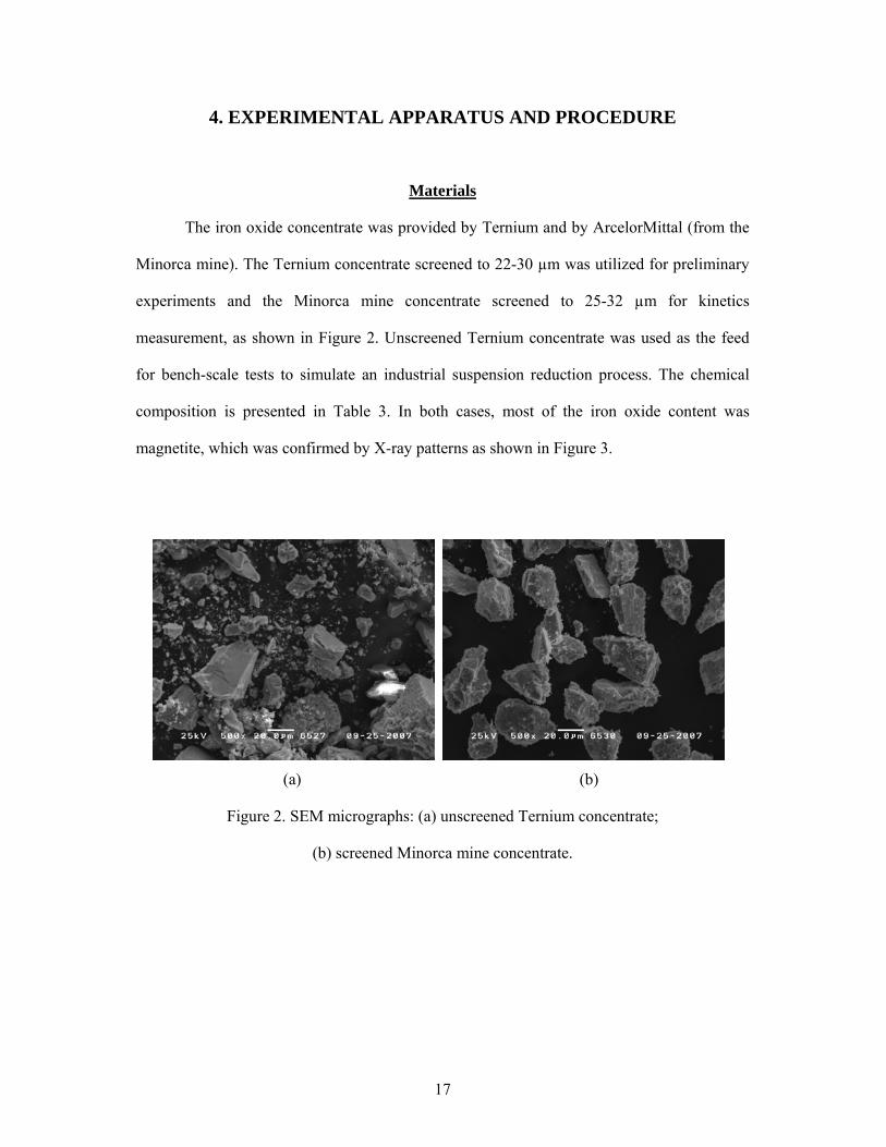
The iron oxide concentrate was provided by Ternium and by ArcelorMittal (from the
Minorca mine). The Ternium concentrate screened to 22-30 µm was utilized for preliminary
experiments and the Minorca mine concentrate screened to 25-32 µm for kinetics
measurement, as shown in Figure 2. Unscreened Ternium concentrate was used as the feed
for bench-scale tests to simulate an industrial suspension reduction process. The chemical
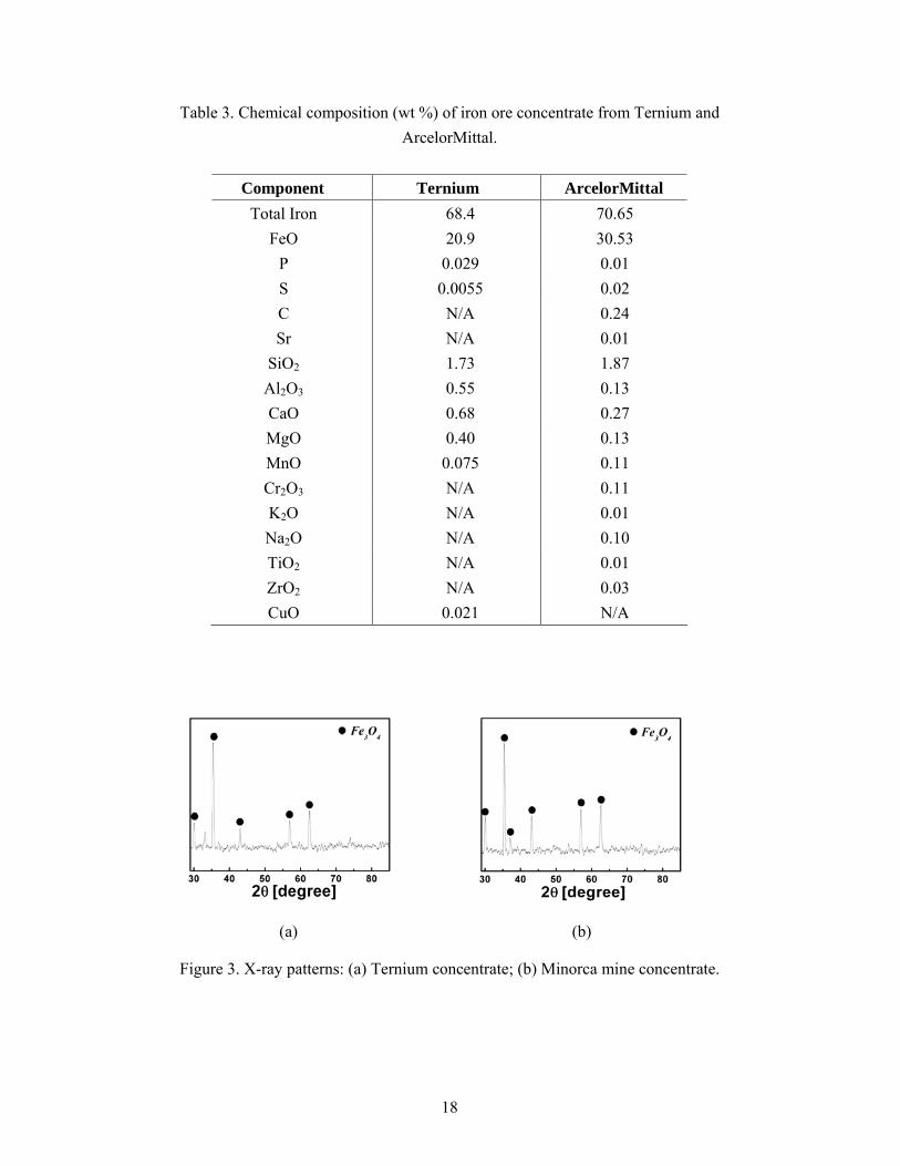
composition is presented in Table 3. In both cases, most of the iron oxide content was
magnetite, which was confirmed by X-ray patterns as shown in Figure 3.
(a) (b)
Figure 2. SEM micrographs: (a) unscreened Ternium concentrate;
(b) screened Minorca mine concentrate.
18
Table 3. Chemical composition (wt %) of iron ore concentrate from Ternium and ArcelorMittal.
Component Ternium ArcelorMittal
Total Iron 68.4 70.65 FeO 20.9 30.53
P 0.029 0.01 S 0.0055 0.02 C N/A 0.24 Sr N/A 0.01
SiO2 1.73 1.87 Al2O3 0.55 0.13 CaO 0.68 0.27 MgO 0.40 0.13 MnO 0.075 0.11 Cr2O3 N/A 0.11 K2O N/A 0.01 Na2O N/A 0.10 TiO2 N/A 0.01 ZrO2 N/A 0.03 CuO 0.021 N/A
(a) (b)
Figure 3. X-ray patterns: (a) Ternium concentrate; (b) Minorca mine concentrate.

19
Preliminary Experiments
Preliminary kinetic experiments were conducted by measuring the weight change of a
22-30 μm concentrate sample over time in pure hydrogen at three different temperatures
900oC, 1000oC, and 1100oC. These experiments were designed to test in a rather simple
facility the kinetic feasibility of reducing concentrate particles within a few seconds of
reaction time that would be available in a suspension reduction process, before more
elaborate and accurate measurements were made.
The concentrate sample was spread on top of a Kaowool compact held in a shallow
ceramic tray in order to remove the effect of inter-particle diffusion of the gaseous species.
This experiment must be considered rather approximate because the conditions were not fully
controlled to determine the fast rate of very fine particle reduction. Possible uncertainties
included the effect of radiation from the furnace wall and the sample holder, which would
affect the measurement of real temperature of the reacting particle, the effect of mass transfer
between the bulk gas and the Kaowool bed, and the effect of minerals in Kaowool on the
reactivity of iron oxide. Hydrogen was fed into the reactor (2 cm ID) at the rate of 2 L/min
when the desired temperature was reached. The apparatus consisted of a horizontal furnace
system, a gas delivery system, a copper turning bed, and an off-gas system as shown below.
Figure 4. Schematic diagram of the horizontal furnace system for preliminary experiments.

20
Kinetics Measurements
For more accurate determination of the reduction rate of individual iron ore
concentrate particles from the Minorca mine, a high temperature drop-tube reactor system
was fabricated. As shown in Figure 5, this apparatus consisted of a vertical high temperature
furnace system, a pneumatic power feeding system, a gas delivery system, a powder cooling
and collecting system, and an off-gas outlet system.
The furnace system was made up of a vertical split tube furnace with a maximum
working temperature of 1540oC and a cylindrical alumina tube (5.6 cm ID, 193 cm long). A
stainless-steel end-cap with five holes was attached to the top of the tube for thermocouples
and reactant feeding. Temperatures at various positions of the reactor were measured by the
use of two B-type thermocouples with alumina protection tubes and a temperature indicator.
Another stainless-steel end-cap with a funnel welded to it to improve the collection of the
reacted particles was attached to the bottom of the alumina tube.
The reacted powder was collected in a powder collector on the bottom of the reactor
shown in Figure 6 and the unreacted hydrogen and water vapor were discharged through the
off-gas outlet system that included a backflow prevention device for safety.
The isothermal hot zone was maintained at a constant temperature of 900 to 1400oC
by heating twenty bar-type SiC elements. Carefully measured isothermal zone was 91 cm
long within ± 20K for typical downward gas flow conditions.

21
(a)
(b)
Figure 5. Schematic diagram of the high temperature drop-tube reactor system
for kinetic measurements: (a) schematic diagram; (b) photograph.

22
(a) (b)
Figure 6. Powder collection system: (a) schematic diagram; (b) photograph.
Pneumatic powder feeding system
Figure 7 shows the pneumatic powder feeding system. The powder feeding system
consisted of a syringe pump, a vibrator, a carrier gas line, a powder container, and a powder
delivery line. Iron ore concentrate particles were held in a vial sealed with an O-ring. The
vial was supported by the piston of a syringe pump which moves at a constant speed. The
carrier gas, hydrogen, was fed into the vial (9 mm ID) and exited through a capillary
discharge tube (1.2 mm ID) at the top of the powder entraining a small amount of the powder
continuously. The whole feeder including the tube between the feeder and the reactor was
vibrated by an electric vibrator to keep the feed rate constant and to prevent clogging. Since
the stainless steel tube in the reactor should be placed in a high temperature region, it had a
double wall for water cooling. The feed rate was calibrated and showed very linear
relationship between the infusion rate of the syringe pump and the feeding rate as shown in
ProductPowder
Filter
Collector
Ball Valve
Gas
End Cap

23
Figure 8. During the experiments, it was controlled from 100 to 600 mg/min.
A powder feeding probe in Figure 7 through which the concentrate particles entrained
by carrier gas passed was enclosed with a water cooling jacket and inserted into the tube
reactor. The tip of the probe was located at the beginning of the isothermal hot zone where
the heating of the concentrate particles and mixing with reactant began.
A cylindrical alumina honey-comb was inserted and hung right above the beginning
of the isothermal zone as a flow straightener and a heat exchanger. Although every effort was
made to improve the heating and mixing of the solid and gaseous species, the reaction zone
where the heterogeneous reaction occurs at the designated temperature is only shorter than
the isothermal hot zone. Thus, the reduction rate presented in this work could be attained in
shorter residence time than the calculated one.
(a)
Powder Container
Ar gas
Powder
SyringePump
Vibrator
CoolingWater
CoolingWater

24
(b)
Figure 7. Pneumatic powder feeding system and the powder feeding probe
with a water jacket: (a) schematic diagram (b) photograph.
Figure 8. Powder feeding rate vs. advancing rate of the syringe pump.

25
Residence time determination
The duration of hydrogen reduction of fine iron ore concentrate particles was
determined by the residence time (τ ) of particles in the isothermal zone. The value of
residence time was found from the length of the isothermal zone, which starts from the tip of
the powder feeding probe, and the terminal falling velocity for the creeping flow region
expressed by the Stokes law (Szekely 1971) assuming that particles fall at a constant velocity
in the isothermal zone. The residence time in this work ranged from 2.0 to 8.5 seconds.
2 ( ) /18t p p gu d g ρ ρ μ= − , p g tu u u= + , / pL uτ = (1)
where pd = particle size, g = gravitational acceleration, pρ = particle density, gρ = gas
density, μ = viscosity of gas, pu = particle velocity relative to tube wall, gu = gas velocity,
tu ; terminal velocity of a falling spherical particle, L ; length of the reaction zone.
The terminal velocity depends not only on the particle size but also the temperature
due to its effect on the gas density and the viscosity of gas. As temperature increases, the
density and viscosity of gas increase and the terminal velocity decreases, as shown in Figure
9. This makes the residence time, namely the reduction time, longer in the same length of the
reaction zone when other parameters are fixed. On the other hand, a higher temperature
causes the gas velocity to decrease at the same molar rate of gas input, which in turn
decreases the residence time. Thus, all these several factors must be taken into consideration
when interpreting the effect of temperature on the reduction rate.

26
Figure 9. Terminal velocity of a falling spherical particle vs. the particle size
% Excess H2.
A hydrogen-containing gas mixture was fed as the reductant into the reactor
concurrently with the pneumatically transported iron ore concentrate, of which the carrier gas
was pure hydrogen. To achieve a high degree of iron oxide reduction, excess hydrogen over
the stoichiometric amount needs to be supplied. The term % excess H2 was defined as
follows, especially paying attention to the fact that the final stage of the iron oxide reduction,
i.e. the reaction of FeO with H2 or CO, is significantly limited by equilibrium. For example,
at 1400oC
)()()()()( C1400cal900GgOHsFegHsFeO oo22 +≈+=+ Δ (2a)
( )[ ] 50pppeqOHHH 222
.=+ (2b)

27
Figure 10. Equilibrium gas compositions vs. temperature
for the FeO - H2 and FeO – CO reactions.
This reaction has a slightly positive standard Gibbs free energy, and the equilibrium
gas product has an H2/H2O molar ratio of 1, i.e. 50% H2 and 50% H2O when pure hydrogen
is used as reductant. The equilibrium gas ratio changes somewhat with temperature as shown
in Figure 10. Taking the equilibrium composition into consideration, % excess H2 was
defined as follows in this work:
)1(3 2243 ROHFeOHOFe +=+ (3a)
)2(22 ROHFeHFeO +=+ (3b)
Overall: OHFeHOFe 2243 434 +=+ (3c)
eqH
OH
eqH
OHR n
npp
K⎥⎥⎦
⎤
⎢⎢⎣
⎡=
⎥⎥⎦
⎤
⎢⎢⎣
⎡=
2
2
2
22 (4)

28
io
RR
ioi
oH nKK
nnn ⎥⎦
⎤⎢⎣
⎡+=+=
22min,
112
(5)
100%min,
min,,sup2
2
22 ×−
=H
HpliedH
nnn
Hexcess (6)
Reaction 1 (R1), the hydrogen reduction of magnetite to wustite, has a large
equilibrium constant, i.e. essentially irreversible, whereas Reaction 2 (R2) is considerably
limited by chemical equilibrium. Thus, the amount of hydrogen ( )eqH2 in equilibrium with
the water vapor present in the gas was used for the equilibrium constant of Reaction 2
represented by Equation (4). The minimum amount of hydrogen, min,2Hn , then is the amount
of hydrogen used to remove the oxygen from the iron oxide, iOn , plus the hydrogen required
by equilibrium to be present with the water vapor produced by the reduction reaction,
iOn /KR2. The % excess H2 was then calculated from the total amount of hydrogen fed into the
reactor ( )totalH 2 compared with the minimum amount of hydrogen, nH2,min , as indicated in
Equation (6).
Degree of reduction
While varying % excess H2 from 1300 down to 0, that is, equivalent to the
equilibrium gas ratio, the concentrate particles were transported downward, heated, reduced
in-flight, and collected. The total iron content in the particles after reduction was determined
by use of an inductively coupled plasma (ICP) emission spectrometer (Perkin Elmer, Plasma
400). The fractional reduction was calculated as follows.
Reduction [%] = ( ) ( )
( ) 100Om
OmOm
oo
ttoo ×−
%%%
(7)
where
mo = mt(%Fe)t/(%Fe)o (8)

29
Here, (%O)o and (%O)t are % oxygen combined with iron in the concentrate before
and after the reduction. mt and mo are, respectively, the mass of a reduced sample used for
ICP analysis, collected after reaction for time t, and the corresponding mass of the unreduced
dry concentrate. (%O)o was obtained as the difference between 100 and the sum of the total
iron content of 70.65% and the total gangue content 3.05% in the ArcelorMittal concentrate
in Table 3. The amount of oxygen in the gangue materials which may be reduced by
hydrogen was negligible and the weight change due to the possible volatile species such as
phosphorus and sulfur was also neglected based on the small contents as given in the table.
Weight loss by heating alone was also confirmed to be negligible. (%O)t was calculated from
(%Fe)t obtained by ICP analysis, assuming the same weight ratio of iron to gangue.
The oxygen and total iron contents in the ArcelorMittal concentrate listed in Table 3
yielded an O/Fe atomic ratio of 1.30, indicating that essentially all the iron oxide exists as
Fe3O4 (O/Fe = 1.33). The fact that all iron oxide in the concentrate exists essentially as Fe3O4
was further confirmed by the XRD pattern presented in Figure 3.
Bench-scale Tests
The kinetic measurements with iron ore concentrate particles from the mine sites
proved that the suspension reduction process was kinetically feasible as will be discussed in
detail below. Based on these results, preliminary scale-up tests were carried out using a
bench-scale test facility shown in Figure 11.

30
(a)
(b)
Figure 11. Bench-scale flash furnace for testing suspension hydrogen reduction
of iron ore concentrate: (a) schematic diagram; (b) photograph.

31
The apparatus consists of five subsystems; a vertical furnace system, an electrical
power control system, a gas delivery system, a preheating system, and a powder feeding
system. A tubular steel reactor (20.3 cm ID, 244 cm long) was electrically heated by six
silicon carbide heating elements, which were grouped into two and managed by two SCR
controllers. The maximum temperature obtained with the set-up was 1150oC in 76 cm long of
isothermal zone.
It is noted that the isothermal zone has a temperature gradient in the radial direction
by the way of heating method unlike the drop-tube reactor system for kinetic measurements
in which the temperature of the isothermal zone was the same as that of heating elements.
For example, to maintain the isothermal zone at 1150oC, the heating elements had to be
heated up to about 1250oC, which introduced temperature gradient in the radial direction of
the tubular reactor and thus the temperature near the inner wall of the tube was higher than
1150oC. In an industrial scale application, the presence of thermal gradient in the vertical and
horizontal directions should be taken into consideration.
All the gaseous species were carefully controlled by flowmeters with high-resolution
valves and flowed through a tubular stainless-steel preheater electrically-heated by a
horizontal furnace system and packed inside with ceramic Raschig rings to improve mixing
and heating of the gas mixture, of which the temperature was measured right before going
into the main reactor and was kept at about 500oC on average.
The Ternium concentrate particles were fed into the reactor by a pneumatic powder
feeding system at about 1.5 g/min rate. The reduction time of the particles was determined by
the residence time of particles in the isotheral zone. In the present work, the residence time
varied from 3.5 to 5.0 seconds and % excess H2 from 0 to ~760%.

32
5. EXPERIMENTAL RESULTS AND DISCUSSION
Preliminary Experiments
About 80% reduction of iron ore concentrate was achieved in 5 seconds at 1100oC in
pure hydrogen in the preliminary experiment, which was described in the previous chapter.
Reduction was almost completed in 10 seconds at the same temperature, as shown in Figure
12. It was assumed that the weight loss during the reduction occurred only due to the loss of
oxygen associated with iron because the components other than iron oxide in the iron ore
concentrate undergo little reaction with hydrogen. Weight loss by heating alone was also
confirmed to be negligible.
Figure 12. Approximate hydrogen reduction rate of iron ore concentrate vs. reaction time at
different temperatures in preliminary experiments.
It was observed that the reduction of Fe3O4 to FeO and to Fe occurred in succession,
as shown in Figure 13, as expected.

33
(a) (b)
(c) (d)
Figure 13. X-ray patterns: (a) initial iron ore concentrate (0% reduction); (b) 30% reduction
at 900oC for 5 seconds; (c) 50% reduction at 1100oC for 2 seconds;
(d) 100% reduction at 1100oC for 10 seconds.
SEM micrographs in Figures 14~16 show that the products became porous as the
hydrogen reduction proceeded and that the porosity increased with the reaction temperature.

34
(a) (b)
Figure 14. SEM micrographs: (a) 30% reduced sample after 5 seconds; (b) 100% reduced
sample after 60 seconds. (T = 900oC)
(a) (b)
Figure 15. SEM micrographs: (a) 32% reduced sample after 2 seconds; (b) 100% reduced
sample after 30 seconds. (T = 1000oC)
(a) (b)
Figure 16. SEM micrographs: (a) 50% reduced sample after 2 seconds; (b) 100% reduced
sample after 10 seconds. (T = 1100oC)

35
Because of the way the preliminary tests were done, in which certain conditions were
left without precise control, the results must be considered as an approximate representation
of the actual rates of reduction of individual particles in suspension reduction conditions.
These experiments, however, verified the fact that a suspension reduction process with only
several seconds of residence time could be feasible for iron production from iron oxide
concentrate particles. Further experiments to measure accurate reduction rate of iron ore
concentrate were conducted using a drop-tube reactor system, as described below.
Kinetics Measurements
In the first series of experiments with hydrogen (with 3-5% N2) as the reducing gas,
over 90% reduction was accomplished in 2.8 seconds and complete reduction in 4.0 seconds
at 1200oC, as shown in Figure 17. The results showed a promising kinetic feasibility of the
suspension reduction process.
Figure 17. Hydrogen reduction rate of iron ore concentrate vs. residence time and % excess
H2 at four different temperatures. [pH2 = 0.85 atm (86.1 kPa)]
(Residence time was varied by the flow rate of hydrogen.)

36
It is noted that there was a considerable increase in the hydrogen reduction rate when
temperature increased from 1100oC to 1200oC, which essentially establishes the lower limit
of the process temperature of the suspension reduction process, considering that the residence
time would be in the same range.
The % reduction was slightly lower as the residence time was increased above 4
seconds. This is because the residence time was increased in these experiments by reducing
the excess H2 used and at a lower % excess H2 the effect of water vapor produced by the
reduction reaction increased. Water vapor not only lowers the partial pressure of hydrogen
but also decreases the thermodynamic reducing power of the gas due to the equilibrium
limitation of the FeO-H2 reaction system (KR2 = 1 at 1400oC).
This point can be further understood by considering the following simplified global
rate expression for iron oxide reduction:
( ) ( )2ROHHappOHHapp KppkppfkR2222
/, −=⋅= (8)
Thus, the presence of water vapor lowers 2Hp and also increases the negative term in
the parentheses.
Further experiments were performed at temperatures higher than 1200oC to obtain
temperature effects. Above 1300oC, complete reduction was accomplished in less than 2.0
seconds in large excess hydrogen, as shown in Figure 18. Complete reduction was achieved
even when excess hydrogen lowered to 40%, which increased the residence time to 8 seconds.
In an industrial application, it would be advantageous to operate the reduction process at a
high rate with lower excess hydrogen input.

37
Figure 18. Hydrogen reduction rate of iron ore concentrate vs. residence time and % excess
H2 at three different temperatures.
Thus, additional experiments were conducted paying attention to the experimental
conditions for moderate excess hydrogen and residence time. At 1200oC, complete reduction
was already achieved in 4.0 seconds at 470% excess hydrogen, as shown in Figure 19. As the
residence time decreased, the reduction degree decreased accordingly. At 1300oC, 90%
reduction was achieved in 4 seconds at 200% excess hydrogen, as shown in Figure 20, which
was 10% higher than that at 1200oC at the same residence time and % excess hydrogen.
When the residence time was increased to 6 seconds, reduction was already completed at
200% excess hydrogen (meaning complete conversion was achieved between 4 and 6
seconds). When the residence time further increased to 8.3 seconds, the complete reduction
began to be observed with only 40% excess hydrogen.

38
Figure 19. Hydrogen reduction rate of iron ore concentrate vs. % excess H2 at 1200oC.
Figure 20. Hydrogen reduction rate of iron ore concentrate vs. % excess H2 at 1300oC.
39
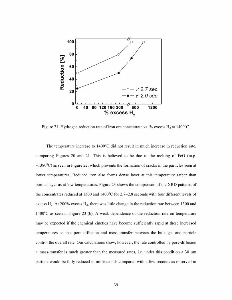
Figure 21. Hydrogen reduction rate of iron ore concentrate vs. % excess H2 at 1400oC.
The temperature increase to 1400oC did not result in much increase in reduction rate,
comparing Figures 20 and 21. This is believed to be due to the melting of FeO (m.p.
~1380oC) as seen in Figure 22, which prevents the formation of cracks in the particles seen at
lower temperatures. Reduced iron also forms dense layer at this temperature rather than
porous layer as at low temperatures. Figure 23 shows the comparison of the XRD patterns of
the concentrates reduced at 1300 and 1400oC for 2.7~2.8 seconds with four different levels of
excess H2. At 200% excess H2, there was little change in the reduction rate between 1300 and
1400oC as seen in Figure 23-(b). A weak dependence of the reduction rate on temperature
may be expected if the chemical kinetics have become sufficiently rapid at these increased
temperatures so that pore diffusion and mass transfer between the bulk gas and particle
control the overall rate. Our calculations show, however, the rate controlled by pore-diffusion
+ mass-transfer is much greater than the measured rates, i.e. under this condition a 30 μm
particle would be fully reduced in milliseconds compared with a few seconds as observed in

40
this work. Thus, the weak increase of rate on temperature between 1300 and 1400oC is
attributed to the change in particle morphology during the reduction reaction. Once the
particle and intermediate product (m.p. of Fe3O4 = 1597oC) form a fully molten phase at
higher temperatures, the reduction rate is expected to increase with temperature more
strongly.
(a)
(b)
Figure 22. SEM micrographs: (a) 100% reduction at 1300oC; (b) 100% reduction at 1350oC.

41
(a) (b)
(c) (d)
Figure 23. X-ray patterns of the reduced concentrate at 1300 and 1400oC in 2.7~2.8 seconds
at: (a) 0% excess H2; (b) 200% excess H2; (c) 500% excess H2; (d) 900% excess H2.
Some agglomeration of concentrate particles were at times observed at low excess
hydrogen and long residence time. Agglomeration was avoided by completely drying the
concentrate and increasing the flow rate of gaseous species. This dispersed the concentrate
particles as soon as they came out of the powder feeding tube inside the reactor. The
agglomeration of fine concentrate particles lowers the reaction rate and thus should be
avoided. Turbulence of the gas-particle flow is expected to be much higher in a large scale
operation. Thus, the problem of agglomeration would be much less.

42
The findings from the current work conclusively show that nearly 100% reduction is
obtained with 40% excess H2 in 8.3 seconds and 90% reduction with 200% excess H2 in 4
seconds at 1300oC. At 1400oC and 200% excess H2, 80% reduction was attained in only 2.7
seconds. Even at 1200 oC, 96% reduction was reached in 5.7 seconds with 200% excess H2.
The variables of the suspension reduction process in an industrial application should be
determined carefully considering the competing factors, the cost of excess hydrogen and
energy for high temperature, and their effect on the total reduction rate.
A temperature higher than 1400oC would be definitely preferable from the kinetics
point of view and moderate % excess H2. This would be required in any case if the reduced
iron is collected as a liquid. Furthermore, incompletely reduced iron ore concentrate can be
further reduced in the molten bath by injecting additional reducing agents into it.
Bench-scale Tests
Larger scale suspension reduction tests were conducted in the bench-scale reactor
described in chapter 4. Again, the highest temperature that could be generated in this reactor
was only 1150oC.
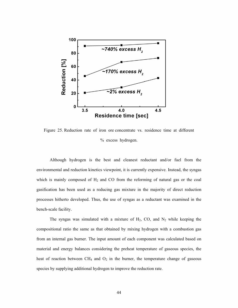
The trend in the change of the reduction rate was observed at three different residence
times; 3.5, 4, and 4.5 seconds in which the reduction extent was at 21, 29, 43%, respectively,
with 0% excess H2 and approached about 95% with 720% excess H2, as shown in Figures 24
and 25. The reduction extent at a longer residence time was always higher while the excess
H2 ranged from 0 to 720% and only 0.5 second difference made a notable change in the
reduction rate.

43
Figure 24. Reduction rate of iron ore concentrate vs. % excess H2 at
different residence times.
Based on the results from the bench-scale tests and the feasibility tests, it is obvious
that the operating temperature of the facility needed to be increased by 100~200oC to obtain
a sufficiently high reduction rate with smaller excess H2 (0~50%) and with increased fine
concentrate feeding rate (1~5 kg/hr). A technical issue that must be overcome is the heat
supply. The heat may be generated internally by burning a portion of the reducing agents, or
supplied by plasma or burning of other fuels. These types of processes in which hot reducing
gas environment is created internally are used in many industrial operations. Examples
include the reforming of natural gas, coal gasification by partial combustion, and the
Horsehead Flame Reactor Process for treating EAF dusts. The main effort in the current
work included addressing this issue in addition to determining the feasibility of achieving
high degrees of reduction in a simulated suspension process.
44
Figure 25. Reduction rate of iron ore concentrate vs. residence time at different
% excess hydrogen.
Although hydrogen is the best and cleanest reductant and/or fuel from the
environmental and reduction kinetics viewpoint, it is currently expensive. Instead, the syngas
which is mainly composed of H2 and CO from the reforming of natural gas or the coal
gasification has been used as a reducing gas mixture in the majority of direct reduction
processes hitherto developed. Thus, the use of syngas as a reductant was examined in the
bench-scale facility.
The syngas was simulated with a mixture of H2, CO, and N2 while keeping the
compositional ratio the same as that obtained by mixing hydrogen with a combustion gas
from an internal gas burner. The input amount of each component was calculated based on
material and energy balances considering the preheat temperature of gaseous species, the
heat of reaction between CH4 and O2 in the burner, the temperature change of gaseous
species by supplying additional hydrogen to improve the reduction rate.
45
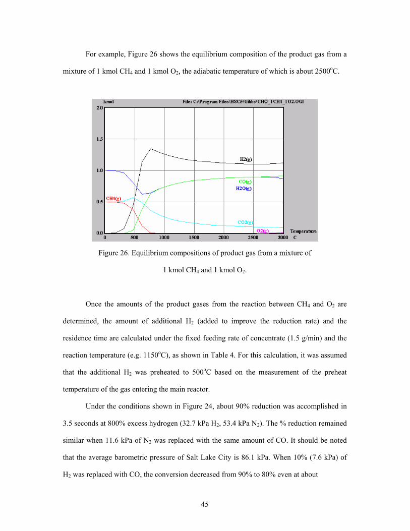
For example, Figure 26 shows the equilibrium composition of the product gas from a
mixture of 1 kmol CH4 and 1 kmol O2, the adiabatic temperature of which is about 2500oC.
Figure 26. Equilibrium compositions of product gas from a mixture of
1 kmol CH4 and 1 kmol O2.
Once the amounts of the product gases from the reaction between CH4 and O2 are
determined, the amount of additional H2 (added to improve the reduction rate) and the
residence time are calculated under the fixed feeding rate of concentrate (1.5 g/min) and the
reaction temperature (e.g. 1150oC), as shown in Table 4. For this calculation, it was assumed
that the additional H2 was preheated to 500oC based on the measurement of the preheat
temperature of the gas entering the main reactor.
Under the conditions shown in Figure 24, about 90% reduction was accomplished in
3.5 seconds at 800% excess hydrogen (32.7 kPa H2, 53.4 kPa N2). The % reduction remained
similar when 11.6 kPa of N2 was replaced with the same amount of CO. It should be noted
that the average barometric pressure of Salt Lake City is 86.1 kPa. When 10% (7.6 kPa) of
H2 was replaced with CO, the conversion decreased from 90% to 80% even at about

46
Table 4. Mass and energy balances in the reduction on the concentrate
CH4
[L/min]
O2
[L/min]
H2
[L/min]
H2O
[L/min]
CO
[L/min]
CO2
[L/min]
Fe3O4
[g/min]
Additional
H2 [L/min]
Residence time
[seconds]
2.571 2.571 2.828 2.314 2.314 0.257 1.5 19.2 3.96
1.571 1.571 1.728 1.414 1.414 0.157 1.5 11.0 4.61
1.143 1.143 1.257 1.028 1.028 0.114 1.5 7.4 4.98
4.5 seconds residence time. Although there was a decrease in reduction rate by introducing
syngas instead of H2, it is still of interest especially at higher operating temperatures. As
temperature increases, the equilibrium ratio of H2/H2O and CO/CO2 changes in the opposite
way, i.e. the thermodynamic reducing power of H2/H2O increases whereas that of CO/CO2
decreases. The amount of hydrogen in a typical syngas of direct reduction process is larger
than that of carbon monoxide and thus the thermodynamic reducing power of the syngas
would rise at higher temperature. In other words, more H2 can be replaced with CO.
Furthermore, the water-gas shift reaction would convert much of CO to H2 by reacting with
water vapor generated by the iron oxide reduction by H2.
Large scale tests in this type of bench-scale reaction or an industrial pilot reactor at
considerably higher temperatures are needed to complete the commercial feasibility of this
suspension reduction technology. Nevertheless, the bench-scale tests performed in this
project combined with the kinetic measurements made in the drop-tube reactor have clearly
demonstrated the kinetic feasibility of the process.

47
6. Sulfur and Phosphorus Behavior
Sulfur and phosphorus contents in hot metals produced by the two ironmaking
processes – blast furnace process and the Suspension Reduction process – were calculated for
comparison. The calculation was done with the same iron ore with chemical composition of
0.04wt% S, 0.04wt% P, 64wt% Fe, 6wt% SiO2 and 2wt% Al2O3.
For blast furnace process, a coke rate of 530 kg per ton of hot metal was assumed,
and the chemical compositions of the coke were: 0.65 wt% S, 0.035 wt% P, 4 wt% SiO2, 3
wt% Al2O3 and C as the remainder. A flux of 131.1 kg CaO and 43.7 kg MgO per ton of hot
metal was also added to get a slag with proper basicity and viscosity for smooth operation
and sufficient S removal. The equilibrium distribution ratio of S between the resultant slag
with a basicity of B = 1.458 (322 %18.094.0%
%7.0%OAlSiO
MgOCaOB++
= ) and the hot metal was
calculated to be 129][%)(%=
SS according to the reported relation between equilibrium
distribution ratio of S and slag basicity. Since S distribution ratio in actual blast furnace
process is around 47% of equilibrium distribution ratio, the actual distribution ratio of S was
taken as 129 x 47% = 60, from which value the mass balance calculation for S leads to the S
content in hot metal by blast furnace process to be [%S] = 0.02.
Blast furnace practice indicated that over 90% of P load enters into hot metal and the
rest is lost either in the slag or in the flue gas or is absorbed in the refractory linings.
Assuming 90% of P enters into hot metal, mass balance calculation for P leads to the P
content in hot metal by blast furnace process to be [%P] = 0.108.
For the suspension reduction process, a slag with higher basicity and thus higher
liquidus temperature can be used for better S removal, since the process has to be operated at
a higher temperature to deal with low carbon hot metal. The slag basicity chosen for this
calculation was B = 1.9. Another critical parameter which determines S distribution ratio is
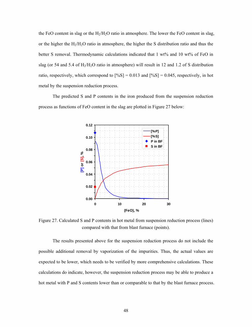
48
the FeO content in slag or the H2/H2O ratio in atmosphere. The lower the FeO content in slag,
or the higher the H2/H2O ratio in atmosphere, the higher the S distribution ratio and thus the
better S removal. Thermodynamic calculations indicated that 1 wt% and 10 wt% of FeO in
slag (or 54 and 5.4 of H2/H2O ratio in atmosphere) will result in 12 and 1.2 of S distribution
ratio, respectively, which correspond to [%S] = 0.013 and [%S] = 0.045, respectively, in hot
metal by the suspension reduction process.
The predicted S and P contents in the iron produced from the suspension reduction
process as functions of FeO content in the slag are plotted in Figure 27 below:
0.00
0.02
0.04
0.06
0.08
0.10
0.12
0 10 20 30
(FeO), %
[P] o
r [S
], %
[%P][%S]P in BFS in BF
Figure 27. Calculated S and P contents in hot metal from suspension reduction process (lines)
compared with that from blast furnace (points).
The results presented above for the suspension reduction process do not include the
possible additional removal by vaporization of the impurities. Thus, the actual values are
expected to be lower, which needs to be verified by more comprehensive calculations. These
calculations do indicate, however, the suspension reduction process may be able to produce a
hot metal with P and S contents lower than or comparable to that by the blast furnace process.
49
7. CONCLUSIONS
A novel alternative ironmaking technology for producing iron directly from fine concentrates by a gas-solid suspension reduction that bypasses cokemaking and pelletization/sintering was thoroughly investigated. The material and energy balance analysis indicate that the suspension reduction process would reduce energy consumption by about 38% of the amount required by the blast furnace and drastically lower environmental pollution, especially CO2 emission, from the steel industry. As a result of concept definition tests with the iron ore concentrate, the reduction rate of fine concentrate particles by hydrogen-containing gases was determined to be sufficiently fast for a suspension technology. From the kinetic measurements and preliminary bench-scale tests, it was found that the reduction temperature should be higher than 1200oC to obtain a sufficiently high reduction rate at moderate excess H2. The use of syngas from the reforming of natural gas or coal gasification as part of the reducing gas mixture in this new process was shown to be feasible.
Further kinetic experiments, under a comprehensive bench-scale testing program are recommended to determine more definitively the relationship among reaction temperature, residence time and % excess gaseous reactant required to achieve 90~100% reduction. In addition, further bench-scale tests with hydrogen and/or syngas are recommended at selected conditions from these additional kinetic experiments, especially at temperatures in the range of 1300~1600oC to fully simulate the method of supplying the energy required to maintain these temperatures, as an intermediate step in determining the scalability for a larger, industrial-scale suspension reduction process pilot test.
The replacement of blast furnaces requires new or improved alternative ironmaking processes that are highly intensive, especially when starting with the fine iron oxide concentrate; the initial project results indicate the Suspension Hydrogen Reduction of Iron Oxide concentrate process presents the highest potential for a high-intensity blast furnace replacement technology.

50
REFERENCES
Brentet, A. et al., “The Port Hedland FINMET Project - Fluid Bed Production of High
Quality Virgin Iron for the 21st Century,” International Conference on Alternative Routes
of Iron and Steelmaking (ICARISM ’99), eds. V. N. Misra and R. J. Holmes (Victoria,
Australia: The Australasian Institute of Mining and Metallurgy, 1999), 111-114.
Chatterjee, A., Beyond the Blast Furnace (Boca Raton, FL: CRC press), 1993, 1-6.
Fruehan, R. J., “Fruehan: Blast-furnace output will continue to fall,” New Steel, 1998, 14 (5),
34-36.
Gupta, C.K. and D. Sathiyamoorthy, Fluid Bed Technology In Materials Processing (Boca
Raton, FL: CRC press), 1999.
Husain, R. et al., ”Circored and Circofer Two New Fine Ore Reduction Processes,”
International Conference on Alternative Routes of Iron and Steelmaking (ICARISM ’99),
eds. V. N. Misra and R. J. Holmes (Victoria, Australia: The Australasian Institute of
Mining and Metallurgy, 1999), 123-132.
IISI, Steel Statistical Yearbook, 2007, accessed January 23, 2008, vial URL http://
www.worldsteel.org/
Macauley, D., “Options increase for non-BF ironmaking,” Steel Times International, 21 (1) (1997), 20
Manning, C. P. and R.J. Fruehan, “Emerging Technologies for Iron and Steelmaking,” JOM,
October 2001, 36-43.
New Steel, Jul. 1999, Vol. 15, issue 7.
Price L. et al., “Energy use and carbon dioxide emissions from steel production in China,”
Energy, 27, 429-446 (2002).
Ritt A., “Reaching for Maximum Flexibility,” New Steel, 16 (1), 2000, 20-26.
Steel Times, Aug.1997.

51
Szekely, J. and N. Themelis, Rate Phenomena in Process Metallurgy (New York, NY:
Wiley-Interscience, 1971).
Thermelis, N. and B. Zhao, in Flash Reaction Processes, Kluwer Academic, 1994, 273.
U.S. Department of Energy, Report: Theoretical Minimum Energies to Produce Steel for
Selected Conditions by Fruehan, Fortini, Paxton and Brindles, March 2000a.
U.S. Department of Energy, Ironmaking Process Alternatives Screening Study, August
2000b, http://www1.eere.energy.gov/industry/steel/pdfs/ironmaking_process.pdf
U.S. Department of Energy, Energy and Environmental Profile of the U.S. Iron and Steel
Industry, Report No. EE-0229, August 2000c,
http://www1.eere.energy.gov/industry/steel/pdfs/steel_profile.pdf
U.S. Department of Energy, Report: Energy Use in the U.S. Steel Industry: An Historic
Perspective and Future Opportunities by J. Stubbles, Table 2, page 8, Sept. 2000d.
U.S. Department of Energy, Hydrogen Posture Plan - An Integrated Research, Development
and Demonstration Plan, December 2006,
http://www.hydrogen.energy.gov/pdfs/hydrogen_posture_plan_dec06.pdf
USGS, Minerals Yearbook - Iron Ore, 2005,
http://minerals.er.usgs.gov/minerals/pubs/commodity/iron_ore/
Wingrove G. et al., “Developments in ironmaking and opportunities for power generation,”
Gasification Technologies Conference, San Francisco, CA, Oct. 17-20, 1999.

52
Appendix A Summary of calculation with the Steel Energy Savings Estimator Tool [Internet tool provided
by AISI] for the suspension reduction technology using natural gas (compared with blast furnace operation excluding cokemaking and pelletization/sintering).
Summary Project Name: Suspension ironmaking User Inputs Process: blast furnace % Energy Savings Natural Gas: -452.0% % of Market Impacted: 20.0% % Energy Savings Electricity: 0.0% Annual Growth Rate: 2.5% % Energy Savings Coal/Coke: 100.0% Year of Introduction: 2012 % Energy Savings Fuel Oil: 100.0% Market Penetration Curve:
10 Year Market Saturation
Solid or Liquid Wastes: 0 lbs per tons of product
Non-Combustion Air Pollutants: 0 lbs per ton of product
Energy Impacts for blast furnace (Based on the input provided above, this technology will have the following impacts:)
2005 2010 2015 2020 MARKET PENETRATION N/A N/A 14.7% 60.8%
MARKET (Million tons) N/A N/A 4 20
ENERGY SAVINGS
Natural Gas Energy Savings (trillion Btu) N/A N/A -34.643 -162.114 Electricity Savings (trillion Btu) N/A N/A 0.000 0.000 Coal Energy Savings (trillion Btu) N/A N/A 41.303 193.278 Fuel Oil Energy Savings (trillion Btu) N/A N/A 1.703 7.970 TOTAL ENERGY SAVINGS N/A N/A 8.363 39.134* POLLUTANT REDUCTIONS (lbs) Carbon (MMTCE/yr) N/A N/A 0.54698 2.55964
Nitrogen Oxides (NOX) N/A N/A 15,510,776 72,583,693
Sulfur Oxides (SOX) N/A N/A
Carbon Monoxide (CO) N/A N/A -1,097,150 -5,134,183
Volatile Organic Compounds (VOCS) N/A N/A -125,108 -522,369
Particulates N/A N/A 1,099,415 5,144,784
Other (million lbs) N/A N/A 0 0
N/A = not applicable
*equivalent to 2.3 GJ/metric ton iron, in agreement with our energy calculation shown Separately in the text below.
USER EXPLANATIONS Technology Description: New technology using natural gas
Market Percentage: 20 million ton/yr iron, which is 20% of steel production
Introduction Year: (Bench + Pilot) testing plus commercialization lead time
Energy Impacts Percentages: Natural gas is used as the reductant and fuel.
Other Wastes and Pollutants: None

53
The baseline input values for the blast furnace operation were obtained as follows, by
adjusting the data given in the table below (imported from "Energy and Environmental
Profile of the U.S. Iron and Steel Industry," U.S. DOE, Report No. EE-0229, August 2000) to
fit into the only four categories provided in the Steel Energy Savings Estimator Tool.
1) Coal/Coke: Coke + Coal + other gases – Top gas credit = 10.7+1.5+1.5–4.0 =9.7
2) Natural gas: 1.8
3) Electricity: 0.2
4) Fuel oil: 0.4
Energy items in a typical blast furnace operation (1998 values) (excluding energy for cokemaking, sintering, and pelletization)
Specific Energy Use Fuel [106 But/short ton hot
metal] [GJ/metric ton hot
metal] Coke 10.7 12.44 Coke oven gas 0.2 0.23 Blast furnace gas 1.0 1.16 Natural gas 1.8 2.09 Fuel oil 0.4 0.47 Coal 1.5 1.74 Electricity 0.2 0.23 Oxygen 0.3 0.35 Subtotal 16.1 18.72 Top gas credit 4.0 4.65 Net total 12.1 14.07
The input values for the technology using natural gas were as follows:
1) Natural gas: 9.93x10⁶ But/short ton [=11.56 GJ/ton] (from the calculation)
Thus, % energy savings natural gas = (1.8-9.93)/1.8*100 = – 452%
2) Electricity: 0.2
3) Coal/Coke: 0
4) Fuel oil: 0
It is not possible to use the Steel Energy Savings Estimator Tool [Internet tool
provided by AISI] for the case of operating the suspension reduction process with hydrogen,
because there is no provision for hydrogen in the input categories. Thus, the energy savings
for the case of using hydrogen was separately calculated by the same procedure as for the
case of using natural gas with this technology, which was verified to be consistent with the
Steel Energy Savings Estimator Tool, and shown in Table 2 in the main text.