doi: 10.1590/s1516-14392011005000008 modelling … · modelling chloride penetration in concrete...
TRANSCRIPT

*e-mail: [email protected]
Modelling Chloride Penetration in Concrete Using Electrical Voltage and Current Approaches
Juan Lizarazo-Marriagaa*, Peter Claisseb
aDepartamento de Ingeniería Civil, Universidad Nacional, Bogotá, Colombia bConstruction Materials Applied Research Group, Coventry University CV1 5FB, UK
Received: August 5, 2010; Revised: February 4, 2011
This paper reports a research programme aimed at giving a better understanding of the phenomena involved in the chloride penetration in cement-based materials. The general approach used was to solve the Nernst-Planck equation numerically for two physical ideal states that define the possible conditions under which chlorides will move through concrete. These conditions are named in this paper as voltage control and current control. For each condition, experiments and simulations were carried out in order to establish the importance of electrical variables such as voltage and current in modelling chloride transport in concrete. The results of experiments and simulations showed that if those electrical variables are included as key parameters in the modelling of chloride penetration through concrete, a better understanding of this complex phenomenon can be obtained.
Keywords: chloride penetration, electrical migration tests, concrete
1. Introduction
The durability of concrete is of primary concern to the engineering community due to the substantial cost of repairing ageing infrastructure. In the majority of cases, weakness and structural breakdown can be directly attributed to damage due to steel corrosion. As the presence of chloride ions heightens the level of metallic corrosion activity, the mechanisms by which such chlorides penetrate the concrete are of great interest.
Despite the large amount of research and computer modelling that has taken place, simplified models for explaining chloride penetration in the concrete are still commonly in use. Fick’s Laws remain in widespread and popular use where a simple approach is thought desirable. Indeed most of the established concrete diffusion models are based around the analytical solution of Fick’s Second Law. Although great advances have been made in these models, and it is common to find models using time-dependent chloride diffusion coefficients or time-dependent chloride binding isotherms1, Fick’s Laws do assume that chlorides are isolated particles. This assumption is not an entirely realistic one, because in the pore solution of concrete, chloride ions will typically be interacting with other ions according to their electrical charge.
One of the reasons why Fick’s Laws have not been completely replaced by other more “appropriate” theories or models is because according to them, the chloride penetration depends entirely on a single parameter, the coefficient of diffusion. To define a complex phenomenon using a single coefficient is a situation that brings several advantages to engineers; however, scientists have known for some time that the Nernst-Planck equation2 should be used to account for possible ionic interactions.
The Nernst-Planck equation includes an electrical field in addition to a gradient of ionic concentration, so it has been proposed as a tool to determine the chloride diffusion coefficient in experimental migration tests as the NTBuild-4923. However, using those approaches the Nernst-Planck model continues to be used assuming the chloride ions are isolated from other species.
Multi-species models have been developed in recent years2,4. These incorporate the presence of several free species in the pore solution (normally OH-, Na+, and K+) along with the chlorides penetrating from the exterior. Although the Nernst-Planck equation governs the phenomenon, it does need to be coupled with the physical principle of charge neutrality, which must be preserved at any point. Even in a self diffusion test, the condition of charge neutrality generates an electric field which affects the flow of each ion. For a multi-ionic system the major difficulty is the determination of those parameters that will define the transport (principally the diffusion coefficients) of all the species involved.
This paper reports a research programme aimed at giving a better understanding of the phenomena involved in the chloride penetration in cement-based materials. The general approach used was to solve the Nernst-Planck equation numerically for two physical ideal states that define the possible conditions under which chlorides will move through concrete. These conditions are named in this paper as voltage and current control. For each condition, simulations were carried out in order to establish the importance of electrical variables such as voltage and current.
2. Modelling-Theoretical Background
2.1. Voltage control
The first condition called “voltage control” is defined by a concrete sample placed between two electrodes that apply a constant potential difference between them and the transient current across the sample is measured. Under this condition a migration test like the ASTM- C12025 or NTBuid-492 can be simulated. The model used in this paper uses a one-dimensional finite difference scheme (divided by space and time steps) to solve the Nernst-Planck equation (Equation 1) that can describe simultaneously the flux of several ionic species under possible driving forces such as diffusion (concentration gradient) and migration (electrical field)6.
DOI: 10.1590/S1516-14392011005000008
Materials Research. 2011; 14(1): 31-38 © 2011

Lizarazo-Marriaga & Claisse
– i ii i i i
C z F EJ D D Cx RT x
∂ ∂= −
∂ ∂ (1)
Ji is the fl ux of species i, D
i is the diffusion coeffi cient of species i,
Ci is the ionic concentration of species i in the pore fl uid, and x is the
distance, where zi is electrical charge of specie i, F is the Faraday
constant, R is the gas constant, T the absolute temperature and E the electrical voltage.
In the electro-diffusion model, the concentration of ions is defi ned in two ways: the free ions per unit volume of liquid (C
l) and the total
ions per unit volume of solid (Cs). The ratio of those concentrations
is named the factor binding capacity (α). In the same way, the intrinsic coeffi cient (D
i) defi nes the transport of matter when the
fl ux is calculated per unit cross-sectional area of the pores and the concentration in the free liquid; and, the apparent diffusion coeffi cient (D
app) defi nes the transport of any ion when the fl ux is calculated per
unit area of the porous material and the average concentration in the material, Equation 2. For chlorides, the binding chloride capacity in the model used a linear isotherm, in contrast, for other species was assumed no binding or adsorption with the cement matrix. By integrating the defi nitions given above it is possible to prove that the ratio chloride intrinsic diffusion to apparent diffusion coeffi cient is equal to the ratio binding factor capacity to porosity.
–
Cl
app cl
DD
α=
ε (2)
During the numerical process, in the model for any time step the fl uxes and the changes of concentration are calculated for all the species involved; however, the model ensures that charge neutrality is maintained throughout the sample at all times for all the ions together. If there is any charge build-up the model corrects the actual migration fl ux until the charge balance is within a specifi ed range. Macroscopically, the procedure to maintain the charge balance is according to Kirchoff’s law: “...the current density (i) into any point will equal the current out of it”. That means that for any time the total current in node i is equal to the current in node i+1, Equation 3.
, 1,t ti k i k
k ki i +=∑ ∑ (3)
In a concrete chloride diffusion or migration test, the charge build-up generated by differences of mobility of ions in the pore solution is dissipated by the distortion of the electrical fi eld. Those effects of voltage changing are applied in the model by distorting iteratively the voltage in each space step removing any build-up of charge. In that way, only a multi-species system can be physically possible because if there is only one ion the charge neutrality never is reached.
That voltage distortion is not just an artifi cial or numerical mechanism, it is a real physical phenomenon measured and reported previously by Lizarazo-Marriaga and Claisse7, who called it non-linear membrane potential due the physical similarities with the liquid-junction potential produced in a porous membrane8. Whenever different ions with different mobilities at different concentrations in the concrete pore solution start to move, there is a tendency for the segregation of charge and the breakdown of the law of electro-neutrality. As a result, several complex and not completely well understood interactions happen in the pore solution, such as the interaction of ions with the solvent or the electrical ion-ion interactions. In order to quantify the ion-ion interactions the more acceptable and used electrochemical theory was that proposed by Debye and Hückel in 1923.
From a “simplistic” microscopic point of view, the Debye and Hückel (ion-cloud) theory can be used to calculate the electrostatic
potential contributed by the surrounding ions to the total electric potential at one reference ion. Once a reference ion is selected, the solvent molecules are replaced by a dielectric continuum medium (ε) and the other ions involved are replaced by an excess of charge density (Figure 1). Assuming that the excess charge distribution is spherically symmetrical around the reference ion, the relationship between excess charge density (ρ
r) and electrostatic potential (ψ
r) at a specifi c radial
distance (r) can be given through Poisson’s equation8, Equation 4.
221 4–r
rdd r
dr drrψ π = ρ ε
(4)
The excess charge density in the volume element dV is obtained in the Debye-Hukel theory through the linearization of the Boltzmann equation8, Equation 5.
2 2–
oi i o
r ri
n z ekT
ρ = ψ∑ (5)
e0 is the electronic charge, n
i is the total number of ions i per unit
volume, k is the Boltzmann constant, and the Σ symbol refers to all the species i. Similarly, the maximum value of charge in a spherical cloud is given through the Debye Huckel length (κ-1), which give an idea about the thickness of the ionic atmosphere, Equation 6.
2 2 24 oi i o
in z e
kTπ
κ = ∑ε
(6)
So, the problem can be simplifi ed and linearized and a general equation can be obtained, Equation 7.
2 221 r
rdd r
dr drrψ = κ ψ
(7)
The solution of which is shown as Equation 8.
– ri o
rz e e
r
κψ =
ε (8)
It can be seen from Equation 8 that the microscopic treatment of the electrostatic potential for the ion-ion interaction has a huge complexity. It has been defi ned for the reference ion as a matter of study; however, it needs to be applied to the whole concrete system.
Going from a micro to a macro approach, a general model with a bigger scale allows a similar, but simpler solution. The simple treatment of the concrete as a circuit in which physical laws must be valid seems to be more appropriate. In that way, the macroscopic electrical model introduced in this paper permits the inclusion of the ion-ion effects coupling all the species involved, to the charge neutrality.
Figure 1. Ionic cloud of an electrical charged element8.
32 Materials Research

Modelling Chloride Penetration in Concrete Using Electrical Voltage and Current Approaches
3. Current Control
In the second condition called “current control” the concrete between two electrodes is subject to a constant electrical current. For this condition, when the current is zero, the phenomenon of normal diffusion with no applied potential can be simulated. If the “current control” condition is used with a non-zero current, the phenomena of either Cathodic protection or electrochemical chloride removal can be modelled.
It is of note that theoretically, when chloride ions are just permitted to diffuse through concrete the system acts like a dry-cell battery and a voltage is developed. Some previous authors have modelled chloride diffusion by simply integrating Fick’s Law and using a diffusion coefficient for chloride ions. The true situation in normal diffusion is, however, far more complex because the voltage that is developed will inhibit further transport unless it is dissipated by further ionic transport. This further transport may be negative ions (such as OH-) moving in the opposite direction to the Cl- or positive ions (such as Na+) moving with them and may be the determining factor for the rate of transport of the Cl-. This should not be modelled with a voltage control algorithm set to zero applied voltage because this implies that the two ends of the sample are short-circuited.
In the numerical algorithm used with a non-zero current control condition, the physical equations used to avoid the charge build-up are the same used previously (voltage control); however, in this approach, in addition to keeping the charge neutrality throughout the sample at all times for all the ions together, it is necessary to keep the current density constant during whole duration of the test. Figure 2 shows a schematic representation of the electrical voltage and current conditions.
4. Experimental Programme
4.1. Materials
A single mortar mixture having a water to cement ratio of 0.36 and a sand-to-binder ratio of 3 was cast. Ordinary Portland cement
CEM I without mineral or chemical admixtures was used. All the specimens were cured under lime water at 21 ± 2 °C prior to testing for 90 days. Because of the low water to cement ratio the mixture had a poor workability, it was compacted manually using prolonged tamping in order to reach its maximum density. Table 1 shows the proportions of the materials used.
4.2. Test methods
Experimental voltage control tests were carried out to ASTM-C1202. Using this standard, a steady external electrical potential of 60 volts D.C was applied to a sample of concrete of 50 mm thick and 100 mm diameter for 6 hours. The anode and cathode were filled with 0.30 N sodium hydroxide and 3.0% sodium chloride solutions, respectively. These samples were prepared before the test in conformity with the ASTM standard. Additionally, the voltage membrane potential was calculated using a salt bridge in a drilled hole in the top of the sample giving readings of the actual voltage in the sample during the test (Figure 3). These readings confirmed that the voltage drop across the sample is not linear and varies with time10,11.
4.3. Calculation of transport properties
The chloride related transport properties needed to simulate the chloride effects on a voltage or current control test for the mixture proposed were obtained from the experimental voltage control results by feeding an artificial neural network with results from the electrochemical model10,11. Table 2 is a summary of the principal transport properties and variables obtained following that methodology. The heat loss factor is a property of the cell and is adjusted to give the observed temperature rise due to the modelled Joule heating in the sample.
Figure 2. Electrical voltage and current approaches9.
Table 1. Mortar mixture proportions.
Water-to-binder ratio
OPC (kg.m–3)
Sand (kg.m–3)
Water (kg.m–3)
0.36 650 1950 234
2011; 14(1) 33

Lizarazo-Marriaga & Claisse
Table 2. Optimized and physical parameters used in the simulations.
Valence (Z)
Intrinsic Concentration (in liquid) (mol.m–3) Binding capacity
factorDiffusion coefficient D (m2/s) Negative In sample Positive
Hydroxyl ion –1 7.877E-11 0 239.973 300 0.171
Chloride ion –1 1.904E-10 530 0.00E + 00 0 0.383
Sodium ion 1 2.061E-11 530 7.92E + 01 300 0.171
Potassium ion 1 4.099E-12 0 1.61E + 02 0 0.171
No of cells 100 Sample length (m) 0.05
Time step (seconds) 2 Sample radius (m) 0.05
Run time (hours) 6 Room temperature (K) 295
Porosity 0.171 Cell volumes (m3) 2.00E-04
Applied voltage (V) 60 Heat loss factor (J.K–1) 0.30
Figure 3. ASTM C1202 test and salt bridge used to measure the membrane potential.
5. Computer Simulations
Using the transport related properties of the optimized mortar (Table 2); the voltage control ASTM C-1202 test was simulated. Additionally, using the same setup and tests conditions, current control tests were simulated under conditions of non-zero current (0.1 A – 6 hours) and zero current (0 A – 12 days).
6. Results and Discussion
6.1. Voltage control
The simulated membrane potential for the mortar mixture is shown in Figure 4 as a colour contour map. It can be observed that the membrane potential is non-linear in time and position and only during the initial time step at the start of the test can the electrical
field be considered linear. If the model is used without the voltage correction, (i.e., no charge neutrality and no coupling among species), the membrane potential would have a value of zero for each time and position.
Figures 5 and 6 show the ionic current carried for anions and cations included in the simulation. Although the total current at any point within the sample should be constant for a specific time, the currents passed by individual ions do not follow this rule and are typically different. From the figures it can be observed that the hydroxide and chloride ions are responsible for most of the total current passed. At the beginning of the test, hydroxyl ions predominate; however, around two hours later, chlorides, which are now penetrating massively into the sample, have begun to control the current being passed. By the end of the test, the chloride ions were responsible for about 80% of the total current. The role of cations
34 Materials Research

Modelling Chloride Penetration in Concrete Using Electrical Voltage and Current Approaches
Figure 4. Membrane potential (V) for the mortar mixture.
Figure 5. Ionic current during the ASTM C1202 test: chloride (left) and hydroxyl ions (right).
Figure 6. Ionic current during the ASTM C1202 test: potassium (left) and sodium (right).
is less important than that of anions; however, they are essential for establishing the necessary conditions of neutrality within the system. Although chloride and hydroxide are much more mobile species, without sodium and potassium the neutrality condition would never be successfully achieved.
Figure 7 shows the simulated current passed for each ion and the total current for three different times of the test. Figure 7a shows the condition where no voltage correction is taken into account in the model, so the condition of charge neutrality is not satisfied (no membrane potential or no ionic coupling). Figure 7b shows similar results using the voltage correction included in the model, where it can be seen that for the same time, the total current in all the length of the sample is the same; however, the contribution of each ion is not necessarily the same.
For the mortar sample simulated, the ionic concentrations of OH-, Cl-, Na+, and K+ are shown in Figure 8 as colour contour maps. At the beginning of the test, chlorides were present only in the cathode external reservoir; however, as the test progressed, chlorides penetrated the specimen and reached the other external cell (anode). Also, from the results of concentrations, it can be seen that prior to the start of the test, the hydroxyl ions were uniformly distributed in the pore solution and in the anode external cell. However, the concentration of those ions increases in the cathode while decreasing in the anode. This behaviour is considered realistic because in an actual test the hydroxyl ions will migrate towards the anode where they are oxidized, releasing electrons. Simultaneously, at the cathode, hydroxyl ions and oxygen are released from water molecules, as a result of electrolysis. The results presented agree well with the findings of Prince, Perami, and Espagne12.
2011; 14(1) 35

Lizarazo-Marriaga & Claisse
Figure 7. Ionic current in a ASTM C1202 test. a) No voltage correction (no ionic interaction); and b) voltage correction (ionic interaction).
6.2. Current control model (non-zero current)
Under a current control condition the concrete sample subjected to a steady known electrical current produces a corresponding external voltage that does not remain constant over time. The simulated voltage generated at different times, under a constant 100 mA, is shown in Figure 9. At the beginning of the test, the voltage drop was linear through the sample; however, voltage deviations were necessary to keep the total current constant. Simulations of ionic current for each ion included in this simulation showed a similar behaviour to that obtained in Figures 5 and 6. Chloride and hydroxyl ions were responsible for the majority of the current carried, while sodium and potassium together carried only a minor amount of the overall current.
The free chloride concentration profile for the 100 mA current control test, simulated at different times, is shown in Figure 10. This test is regarded as a non-steady condition, the source reservoir is depleting over time and the chloride ions are just beginning to reach the anode reservoir.
6.3. Current control model (zero current)
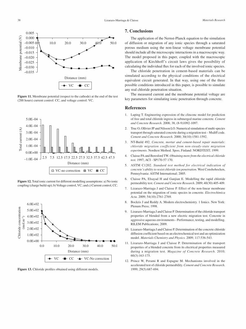
This condition reflects a standard diffusion cell using the same cells and solutions stated in the standard ASTM C1202 test but with no applied voltage. Figure 11 shows the membrane potential results across the entire sample obtained from the numerical current and voltage control modes at the end of the test (12 days). In the voltage
control model, the membrane potential across the whole sample, between anode and cathode (50 mm), was equal to zero. This was expected because the voltage control states an external voltage applied of 0 V (i.e. an electrical short circuit connecting the ends of the sample). In contrast, although the applied external current was zero, the current control model showed a value of membrane potential of -0.03 V between anode and cathode.
Figure 12 shows the results of total current calculated at 12 days of diffusion for different modelling conditions. As was expected, using the current control model (CC), the total current simulated at different positions at the end of the test was always approximately equal to zero. In contrast, for the voltage control model (VC) with the applied voltage equal to zero, a small total current was developed (0.00008 A). It is important to notice that in both models, the charge neutrality condition was fulfilled, but in the current control condition it was forced to be equal to zero. In contrast, the simulations of the total current without coupling all the species involved (VC-no correction) give very high numerical values of current because the charge neutrality is not met in full. Under this last condition, the Nernst-Plank equation is solved independently for each ion and as the external voltage is equal to zero, the model at the end solves the Fick’s equation for each ion.
The simulated chloride profile for the voltage and current control conditions at 12 days is shown in Figure 13. Although the membrane potential and the current obtained from both models were different, important differences were not found between the concentration
36 Materials Research

Modelling Chloride Penetration in Concrete Using Electrical Voltage and Current Approaches
Figure 8. ASTM C-1202 concentrations for hydroxyl, chloride, sodium and potassium (mol.m–3).
chloride profi les - the concentrations for both models at that specifi c time were very similar. In contrast, the profi le obtained using the voltage control with no charge neutrality (i.e., Fick’s law) is very different and a higher amount of chlorides are simulated.
Figure 9. Voltage adjustments at different times (100 mA) during the current control condition.
Figure 10. Chloride profi le at different times during the current control condition (100 mA).
2011; 14(1) 37
Lizarazo-Marriaga & Claisse
7. Conclusions
The application of the Nernst-Planck equation to the simulation of diffusion or migration of any ionic species through a saturated porous medium using the non-linear voltage membrane potential should include all the microscopic interactions in a macroscopic way. The model proposed in this paper, coupled with the macroscopic application of Kirchhoff’s circuit laws gives the possibility of calculating the individual flux for each of the involved ionic species.
The chloride penetration in cement-based materials can be simulated according to the physical conditions of the electrical equivalent circuit generated. In that way, using one of the three possible conditions introduced in this paper, is possible to simulate any real chloride penetration situation.
The measured current and the membrane potential voltage are key parameters for simulating ionic penetration through concrete.
References1. Luping T. Engineering expression of the clinconc model for prediction
of free and total chloride ingress in submerged marine concrete. Cement and Concrete Research. 2008; 38, (8-9)1092-1097.
2. Truc O, Ollivier JP and Nilsson LO. Numerical simulation of multi-species transport through saturated concrete during a migration test – Msdiff code. Cement and Concrete Research. 2000; 30(10):1581-1592.
3. NT-Build 492. Concrete, mortar and cement-based repair materials: chloride migration coefficient from non-steady-state migration experiments. Nordtest Method. Spoo, Finland: NORDTEST; 1999.
4. Claisse PA and Beresford TW. Obtaining more from the electrical chloride test. 1997; ACI - SP170-57 170.
5. ASTM C1202. Standard test method for electrical indication of concrete’s ability to resist chloride ion penetration. West Conshohocken, Pennsylvania: ASTM International; 2005.
6. Claisse PA, Elsayad H and Ganjian E. Modelling the rapid chloride permeability test. Cement and Concrete Research. 2009; 40(30):405-409.
7. Lizarazo-Marriaga J and Claisse P. Effect of the non-linear membrane potential on the migration of ionic species in concrete. Electrochimica Acta. 2009; 54(10):2761-2769.
8. Bockris J and Reddy A. Modern electrochemistry. 1 Ionics. New York: Plenum Press; 1998.
9. Lizarazo-Marriaga J and Claisse P. Determination of the chloride transport properties of blended from a new electric migration test. Concrete in aggressive aqueous environments - Performance, testing, and modelling. RILEM Publications; 2009.
10. Lizarazo-Marriaga J and Claisse P. Determination of the concrete chloride diffusion coefficient based on an electrochemical test and an optimization model. Materials Chemistry and Physics. 2009; 117:536-543.
11. Lizarazo-Marriaga J and Claisse P. Determination of the transport properties of a blended concrete from its electrical properties measured during a migration test. Magazine of Concrete Research. 2010; 60(3):163-175.
12. Prince W, Perami R and Espagne M. Mechanisms involved in the accelerated test of chloride permeability. Cement and Concrete Research. 1999; 29(5):687-694.
Figure 11. Membrane potential (respect to the cathode) at the end of the test (288 hours) current control: CC, and voltage control: VC.
Figure 12. Total ionic current for different modelling assumptions: a) No ionic coupling (charge build-up); b) Voltage control, VC; and c) Current control, CC.
Figure 13. Chloride profiles obtained using different models.
38 Materials Research