dolphin integration tames-2 workshop 23/05/2004 corsica1 behavioural error injection, spectral...
TRANSCRIPT
TAMES-2 workshop 23/05/2004 Corsica 1
DOLPHININTEGRATION
Behavioural Error Injection, Spectral Analysis and Error
Detection for a 4th order Single-loop Sigma-delta Converter
Using Walsh transformsKostas Georgopoulos, Martin Burbidge,
Andreas Lechner and Andrew Richardson
2
DOLPHININTEGRATION
TAMES-2 workshop 23/05/2004 Corsica © Lancaster University
Presentation Overview
The Sigma-Delta A/D Converter
The Walsh functions and Walsh series
Motivation for work
The FFT error simulation analysis
The Walsh error simulation analysis
Conclusions
Future Work

3
DOLPHININTEGRATION
TAMES-2 workshop 23/05/2004 Corsica © Lancaster University
The Sigma-Delta A/D Converter (I)
A device comprised by three stages
Anti-aliasing filter
Sigma-Delta modulator
Decimation phase
Analogue Input
Digital Output
Anti-aliasing Filtering
Modulator
Decimation Process – Digital Filtering
Modulated Input Signal – High frequency bit stream
4
DOLPHININTEGRATION
TAMES-2 workshop 23/05/2004 Corsica © Lancaster University
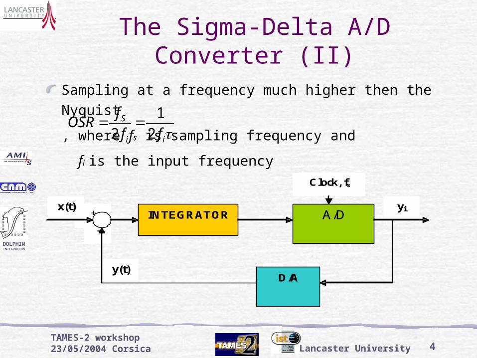
The Sigma-Delta A/D Converter (II)
Sampling at a frequency much higher then the Nyquist
, where fs is sampling frequency and
fi is the input frequency
-
+ x(t) yi
y(t)
INTEGRATOR A/D
D/A
Clock, fs
ii
S
ff
fOSR
2
1
2
5
DOLPHININTEGRATION
TAMES-2 workshop 23/05/2004 Corsica © Lancaster University
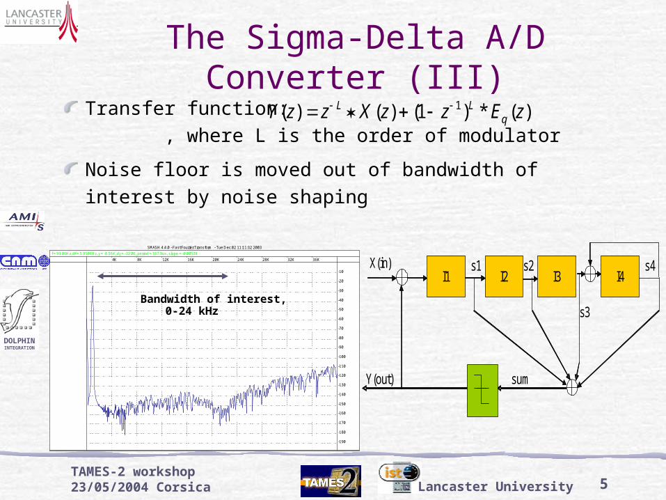
The Sigma-Delta A/D Converter (III)
Transfer function: , where L is the order of modulator
Noise floor is moved out of bandwidth of interest by noise shaping
s1
I1
I2 s2
I3
s3
I4 s4 X(in)
Y(out)
sum
SMASH 4.4.0 - Fast Fourier Transform - Tue Dec 02 11:11:32 2003
BH7(filter_1000.00)
f = 99.06Hz, df = 5.958KHz, y = -8.564, dy = -32.06, period = 167.9us, slope = -0.00538
4K 8K 12K 16K 20K 24K 28K 32K 36K
-190
-180
-170
-160
-150
-140
-130
-120
-110
-100
-90
-80
-70
-60
-50
-40
-30
-20
-10
Bandwidth of interest, 0-24 kHz
)(*)1()()( 1 zEzzXzzY qLL
6
DOLPHININTEGRATION
TAMES-2 workshop 23/05/2004 Corsica © Lancaster University
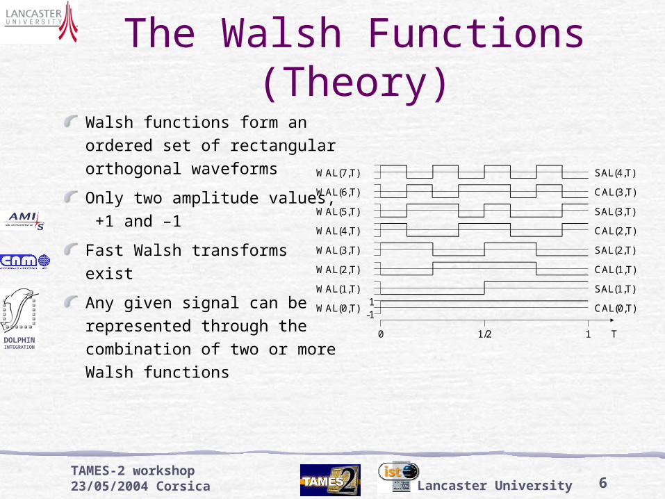
The Walsh Functions (Theory)
Walsh functions form an ordered set of rectangular orthogonal waveforms
Only two amplitude values, +1 and –1
Fast Walsh transforms exist
Any given signal can be represented through the combination of two or more Walsh functions
1
0 1/2 1
-1
T
SAL(4,T)
CAL(3,T)
SAL(3,T)
CAL(2,T)
SAL(2,T)
CAL(1,T)
SAL(1,T)
CAL(0,T)
WAL(7,T)
WAL(6,T)
WAL(5,T)
WAL(4,T)
WAL(3,T)
WAL(2,T)
WAL(1,T)
WAL(0,T)
7
DOLPHININTEGRATION
TAMES-2 workshop 23/05/2004 Corsica © Lancaster University
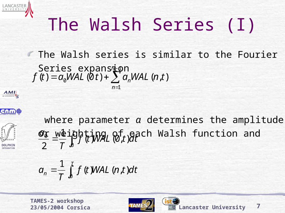
The Walsh Series (I)
The Walsh series is similar to the Fourier Series expansion
where parameter α determines the amplitude or weighting of each Walsh function and
),().0()(1
10 tnWALatWALatf
N
nn
T
dttWALtfT
a0
0 ),0()(1
2
T
n dttnWALtfT
a0
),()(1
8
DOLPHININTEGRATION
TAMES-2 workshop 23/05/2004 Corsica © Lancaster University
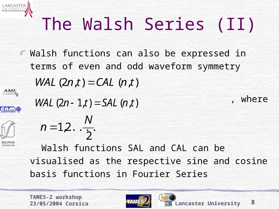
The Walsh Series (II)
Walsh functions can also be expressed in terms of even and odd waveform symmetry
, where
Walsh functions SAL and CAL can be visualised as the respective sine and cosine basis functions in Fourier Series
),(),2( tnCALtnWAL
),(),12( tnSALtnWAL
2....2,1
Nn

9
DOLPHININTEGRATION
TAMES-2 workshop 23/05/2004 Corsica © Lancaster University
The Walsh Series (III)
Employing SAL and CAL functions a Walsh Series similar to the sine-cosine series is given
where
f(t) is the sum of a series of square-wave shaped functions
)),(),((),0()(2/
1
2/
10 tjCALbtiSALatWALatf j
N
i
N
ji
T
j dttjCALtfT
b0
),()(1
T
i dttiSALtfT
a0
),()(1
10
DOLPHININTEGRATION
TAMES-2 workshop 23/05/2004 Corsica © Lancaster University
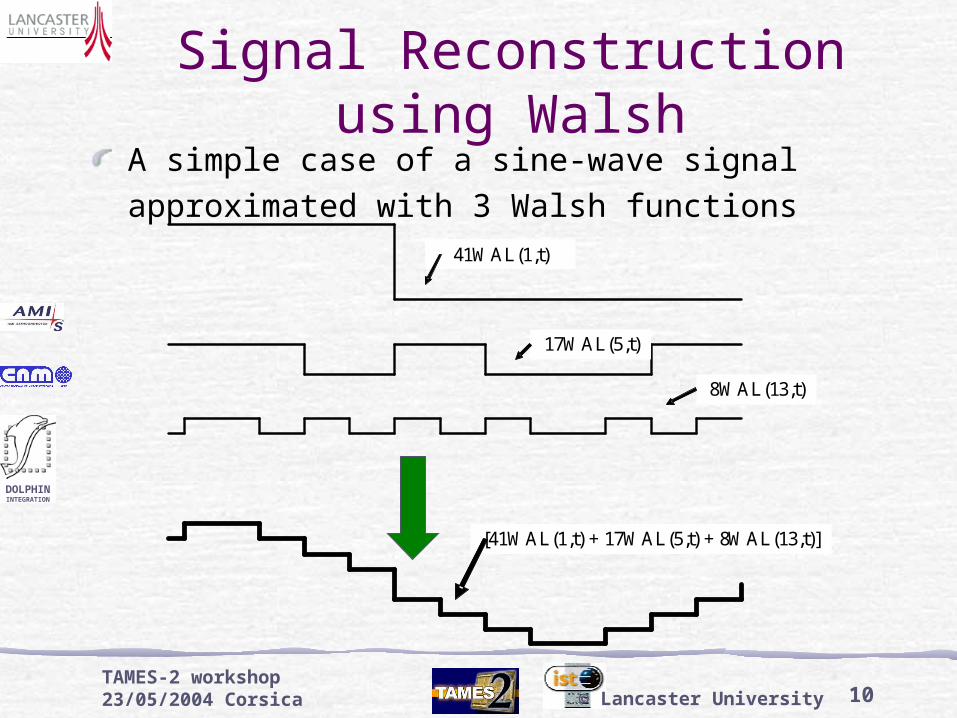
Signal Reconstruction using Walsh
A simple case of a sine-wave signal approximated with 3 Walsh functions
41WAL(1,t)
17WAL(5,t)
8WAL(13,t)
[41WAL(1,t) + 17WAL(5,t) + 8WAL(13,t)]
11
DOLPHININTEGRATION
TAMES-2 workshop 23/05/2004 Corsica © Lancaster University
Motivation & MethodologyFFT converges rapidly to sine wave hence use for classic dynamic performance testing
Walsh converges rapidly to square wave:Idea to use square wave for input to modulator
Walsh transform of bit-stream should give single spectral peak
All other peaks in spectrum are due to noise and non-idealities
Higher potential for on-chip transform of fewer samples
Methodology:
Determine modulator behavior and model parameters that lead to performance failure in FFT domain
Analyse effect of these failure modes on Walsh results

12
DOLPHININTEGRATION
TAMES-2 workshop 23/05/2004 Corsica © Lancaster University
Use of initial C-based model provided by Dolphin
Ideal model FFT S/(N + THD) results:
Input 2.5 Vpk sine @ 1 kHz
BW approx 24 kHz (150 Hz to 24 kHz)
S/(N+THD) approx 100dB
Next step: Analyse how Walsh transforms could compare to FFT
FFT Analysis Setup
13
DOLPHININTEGRATION
TAMES-2 workshop 23/05/2004 Corsica © Lancaster University
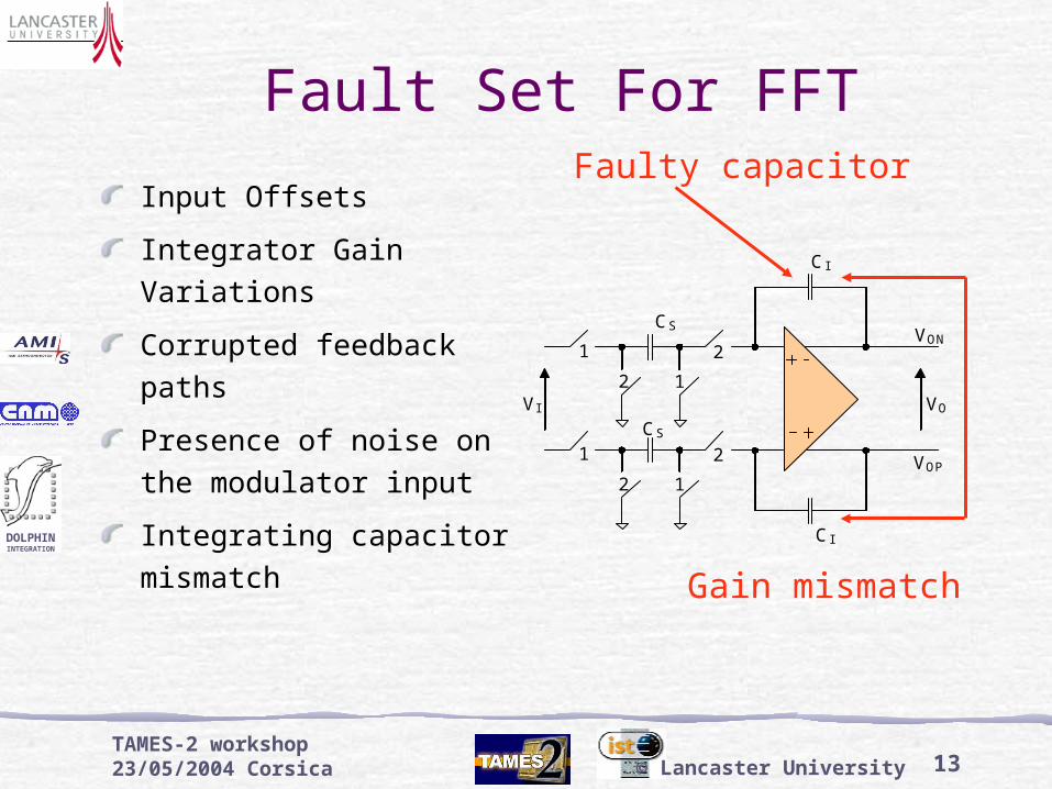
Fault Set For FFT
Input Offsets
Integrator Gain Variations
Corrupted feedback paths
Presence of noise on the modulator input
Integrating capacitor mismatch
1
1 2
2
CS VON
1
1 2
2
CS
CI
VOP
VO
CI
VI
Faulty capacitor
Gain mismatch
14
DOLPHININTEGRATION
TAMES-2 workshop 23/05/2004 Corsica © Lancaster University
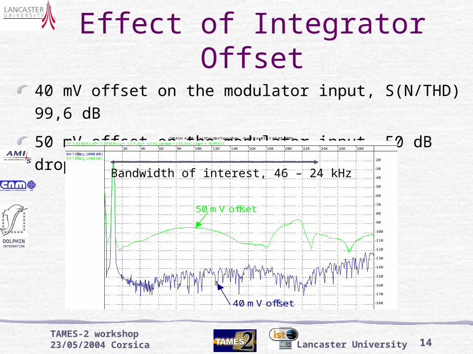
Effect of Integrator Offset
40 mV offset on the modulator input, S(N/THD) 99,6 dB
50 mV offset on the modulator input, 50 dB drop in S(N/THD)
SMASH 4.4.0 - Fast Fourier Transform - Wed Mar 03 17:44:45 2004
BH7(filter_1000.00)BH7(filter_1000.00)
f = 3.015KHz, df = 7.394KHz, y = -13.7, dy = -24.61, period = 135.3us, slope = -0.00333
2K 4K 6K 8K 10K 12K 14K 16K 18K 20K 22K 24K 26K 28K
-180
-170
-160
-150
-140
-130
-120
-110
-100
-90
-80
-70
-60
-50
-40
-30
-20
50 mV offset
40 mV offset
Bandwidth of interest, 46 – 24 kHz
15
DOLPHININTEGRATION
TAMES-2 workshop 23/05/2004 Corsica © Lancaster University
Analyses of Walsh Testing
Setup:
Square wave test stimulus, @ 1.5kHz, 1.9 to 2.3 V amplitude
Bit-stream frequency of 3.072 MHz, analysis on the bit stream with 16384 and 65536 (1-bit) samples.
Analyses:
Investigation into test stimulus accuracy requirements
Assessment of Walsh-based modulator performance tests
Analysis of Walsh test coverage against modulator failure modes

16
DOLPHININTEGRATION
TAMES-2 workshop 23/05/2004 Corsica © Lancaster University
Test Stimulus Accuracy (I)
Finite rise/fall time: No significant effect
Overshoots:
4% of maximum amplitude, i.e. 0.08 V for 2 V input
16384 samples
Overshoots Damping (ms) SNR (dB)
Ideal - 97.6
Max. amplitude 2.05 V 0.06 95,9
0.14 94.7
Max. amplitude 2.15 V 0.06 95.5
0.14 94.6

17
DOLPHININTEGRATION
TAMES-2 workshop 23/05/2004 Corsica © Lancaster University
Test Stimulus Accuracy (II)SNR with respect to different input amplitudes
Analysis for both 16384 and 65536 samplesSquare wave amplitude (V) # samples SNR (dB)
1.9 16384 93.9
2.0 97.6
2.1 94.8
2.2 93.2
2.3 9.7
1.9 65536 104.4
2.0 107.5
2.1 107.6
2.2 102.4
2.3 3.4
18
DOLPHININTEGRATION
TAMES-2 workshop 23/05/2004 Corsica © Lancaster University
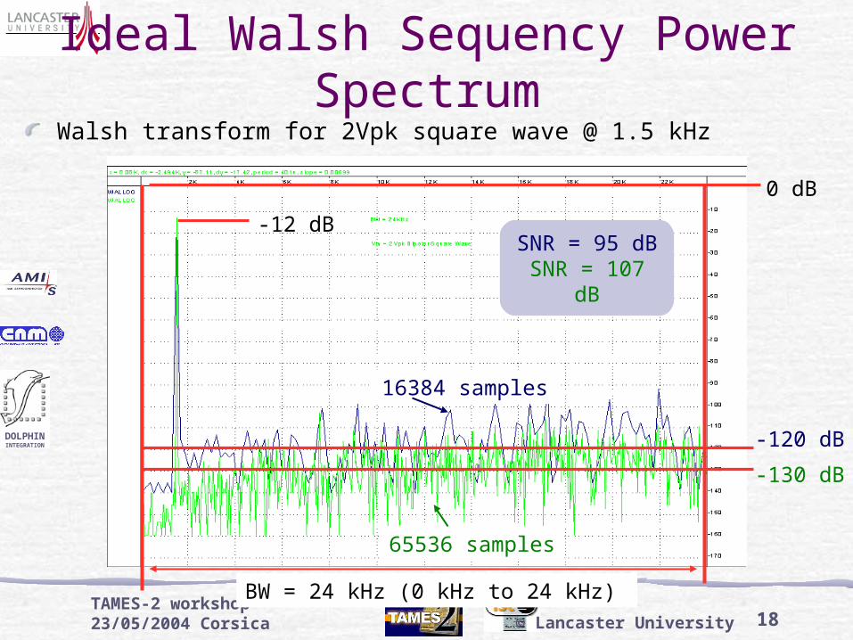
Ideal Walsh Sequency Power Spectrum
BW = 24 kHz (0 kHz to 24 kHz)
0 dB
-130 dB
16384 samples
65536 samples
-120 dB
-12 dB
Walsh transform for 2Vpk square wave @ 1.5 kHz
SNR = 95 dBSNR = 107 dB
19
DOLPHININTEGRATION
TAMES-2 workshop 23/05/2004 Corsica © Lancaster University
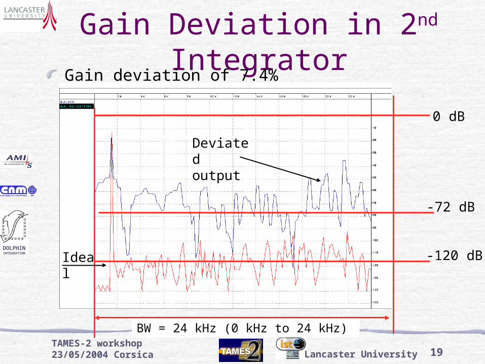
Gain Deviation in 2nd Integrator
Gain deviation of 7.4%
-72 dB
-120 dB
0 dB
Ideal
Deviated output
BW = 24 kHz (0 kHz to 24 kHz)
20
DOLPHININTEGRATION
TAMES-2 workshop 23/05/2004 Corsica © Lancaster University
SMASH 4.4.0 - Generic - Tue Mar 23 13:03:01 2004
WALLOGWALLOG
2K 4K 6K 8K 10K 12K 14K 16K 18K 20K 22K 24K 26K 28K
-180
-170
-160
-150
-140
-130
-120
-110
-100
-90
-80
-70
-60
-50
-40
-30
-20
-10
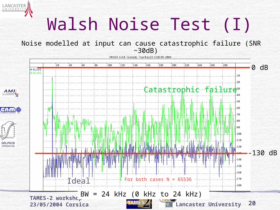
Walsh Noise Test (I)
0 dB
-130 dB
For both cases N = 65536
Noise modelled at input can cause catastrophic failure (SNR ~30dB)
BW = 24 kHz (0 kHz to 24 kHz)
Ideal
Catastrophic failure

21
DOLPHININTEGRATION
TAMES-2 workshop 23/05/2004 Corsica © Lancaster University
Walsh Noise Test (II)FFT – Smoother transition to performance failure
Walsh – Sudden transition to catastrophic failure
50
60
70
80
90
100
110
1.0E-08 1.0E-07 1.0E-06 1.0E-05 1.0E-04 1.0E-03 1.0E-02Maximum noise amplitude (V)
SN
R (d
B)
FFT 2.5 V
Walsh,N=2^12, 2.0 V
Walsh,N=2^12, 2.1 V
Walsh,N=2^12, 2.2 V
Walsh,N=2^14, 2.1 V
Walsh,N=2^14, 2.2 V
Transition for 216 samples
22
DOLPHININTEGRATION
TAMES-2 workshop 23/05/2004 Corsica © Lancaster University
Summary and Future WorkSummary
Failure Insertion in C-based models => FFT results
Usage of Walsh Transforms with square wave inputs for spectral analysis
Initial Potential for Walsh SNR test assessed
Test Stimulus Requirements
Challenges and Limitations Identified
Future Work
Expansion of existing fault simulation data for Walsh applicability
Investigation into hardware implementation and test stimulus generation
Investigation into hybrid test solution