dominic filion, senior engineer blizzard entertainment … · dominic filion, senior engineer...
TRANSCRIPT

Dominic Filion, Senior Engineer
Blizzard Entertainment
Rob McNaughton, Lead Technical Artist
Blizzard Entertainment
Screen-space techniques
Deferred rendering
Screen-space ambient occlusion
Depth of Field
Translucent Shadows
DX9-based
Scalability GPU families from Radeon 9800/geForce FX to latest
families supported, with maximal usage of each family
Pixel load vs. vertex load Stress pixel vs. vertex/batch processing due to fluctuating,
high unit counts
Translates into focus on stressing GPU over CPU to ensure consistent framerate
Dual mode Game mode: overhead view, many units, lot of action
Story mode: close-up view, few models, contemplative
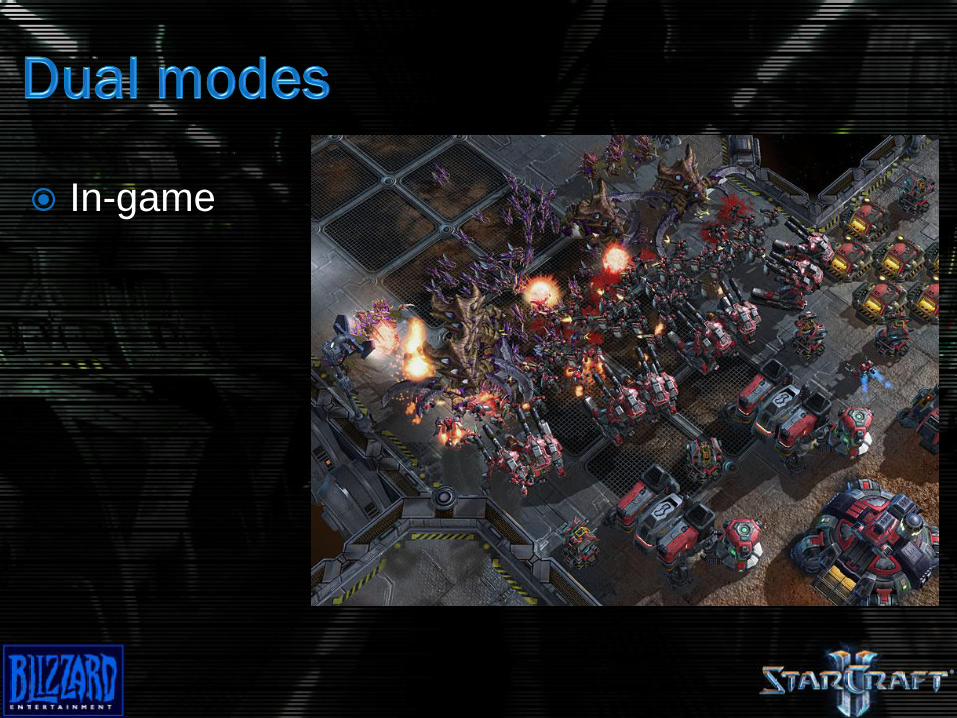
In-game
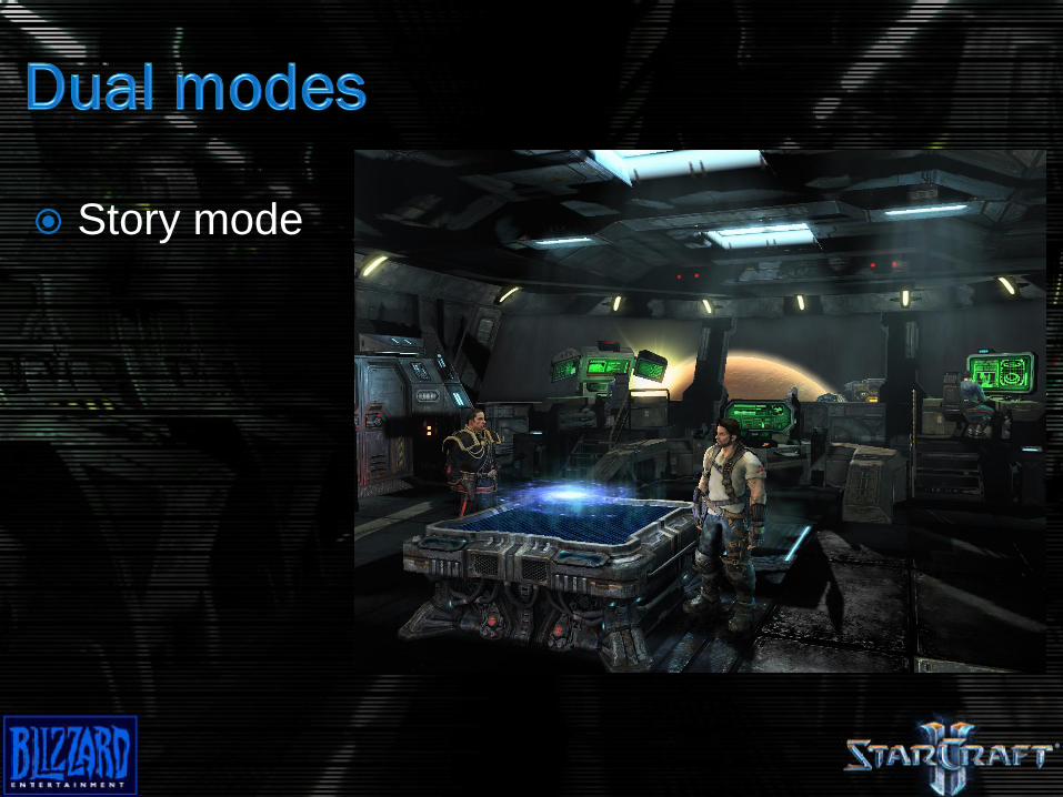
Story mode
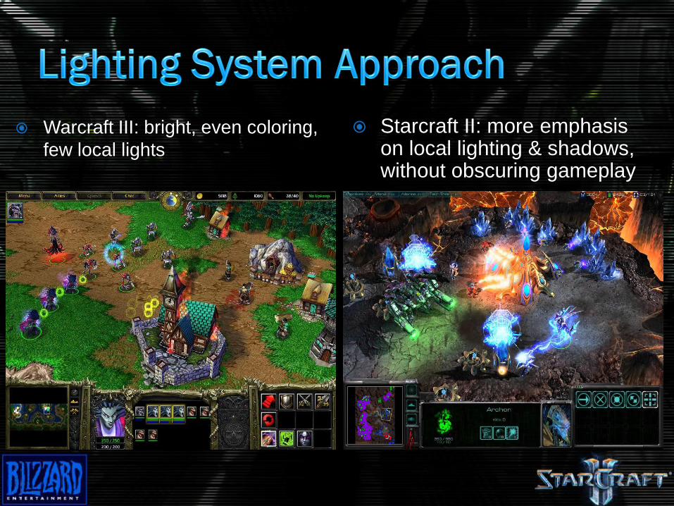
Warcraft III: bright, even coloring,
few local lights
Starcraft II: more emphasis on local lighting & shadows, without obscuring gameplay
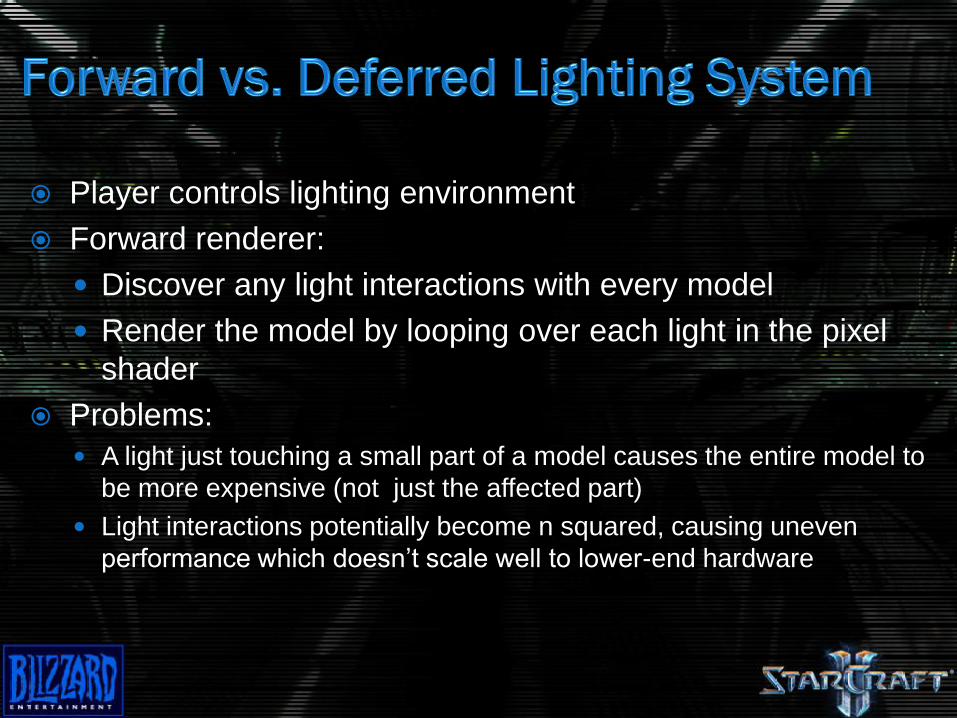
Player controls lighting environment
Forward renderer:
Discover any light interactions with every model
Render the model by looping over each light in the pixel
shader
Problems:
A light just touching a small part of a model causes the entire model to
be more expensive (not just the affected part)
Light interactions potentially become n squared, causing uneven
performance which doesn’t scale well to lower-end hardware
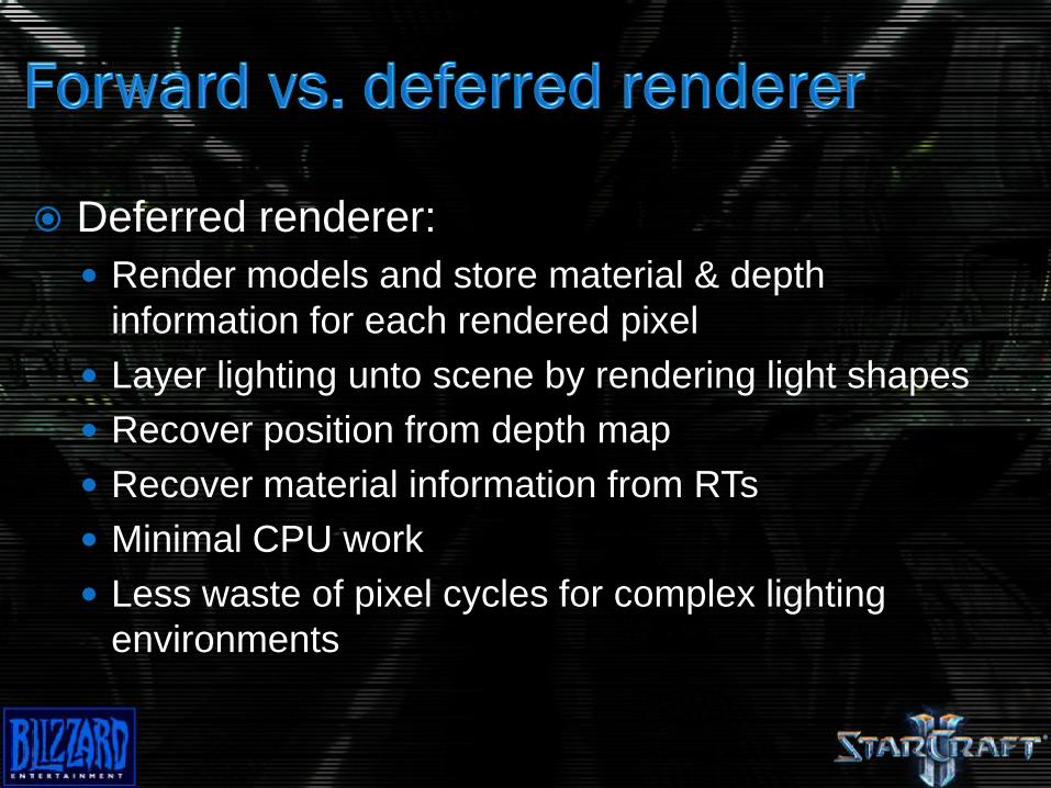
Deferred renderer:
Render models and store material & depth
information for each rendered pixel
Layer lighting unto scene by rendering light shapes
Recover position from depth map
Recover material information from RTs
Minimal CPU work
Less waste of pixel cycles for complex lighting
environments
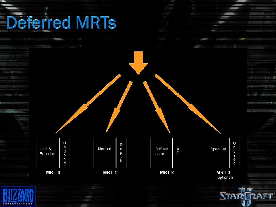
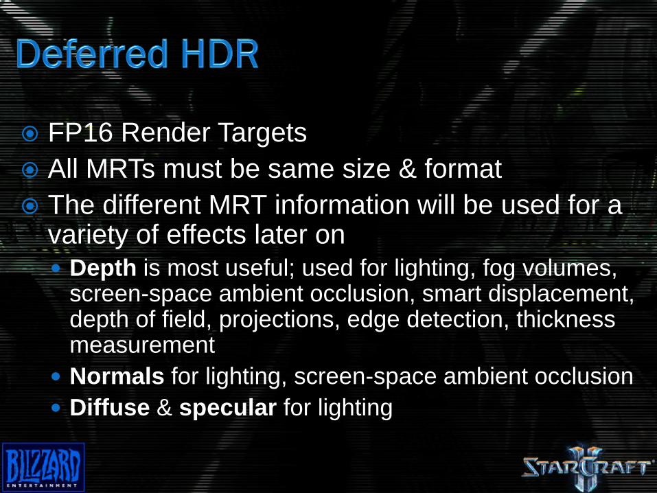
FP16 Render Targets
All MRTs must be same size & format
The different MRT information will be used for a variety of effects later on
Depth is most useful; used for lighting, fog volumes, screen-space ambient occlusion, smart displacement, depth of field, projections, edge detection, thickness measurement
Normals for lighting, screen-space ambient occlusion
Diffuse & specular for lighting
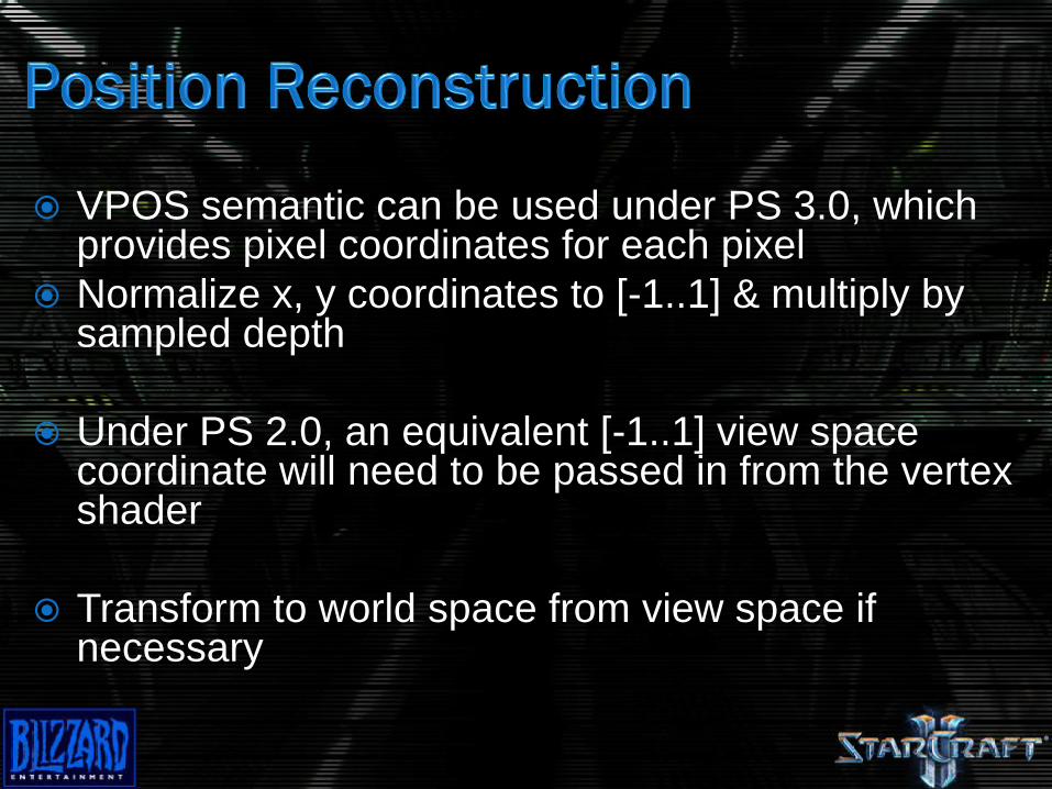
VPOS semantic can be used under PS 3.0, which provides pixel coordinates for each pixel
Normalize x, y coordinates to [-1..1] & multiply by sampled depth
Under PS 2.0, an equivalent [-1..1] view space coordinate will need to be passed in from the vertex shader
Transform to world space from view space if necessary
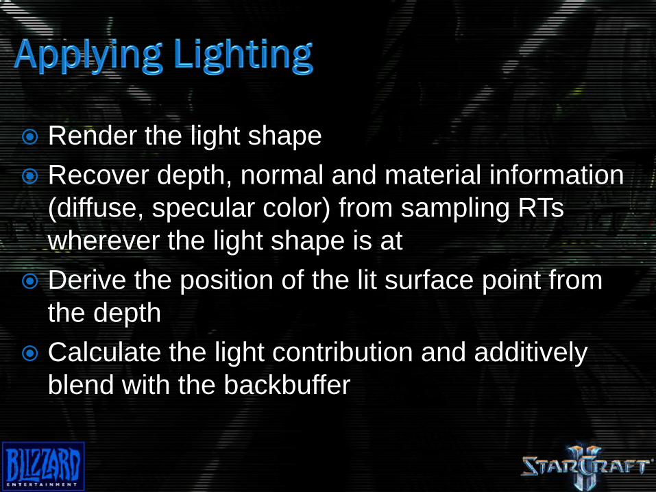
Render the light shape
Recover depth, normal and material information
(diffuse, specular color) from sampling RTs
wherever the light shape is at
Derive the position of the lit surface point from
the depth
Calculate the light contribution and additively
blend with the backbuffer
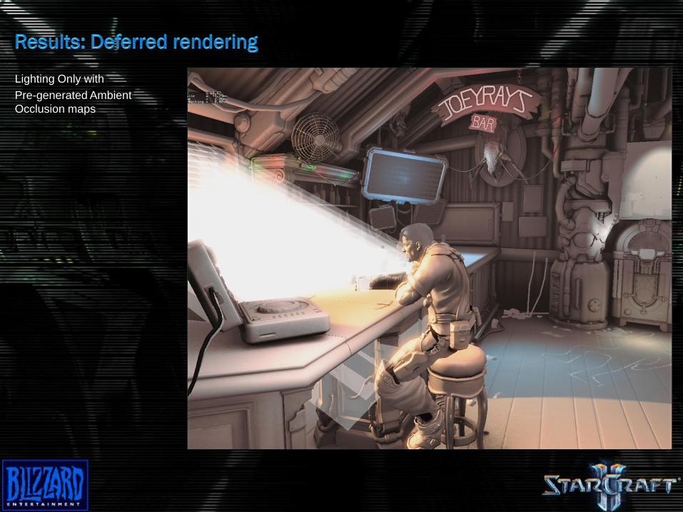
Lighting Only with
Pre-generated Ambient
Occlusion maps
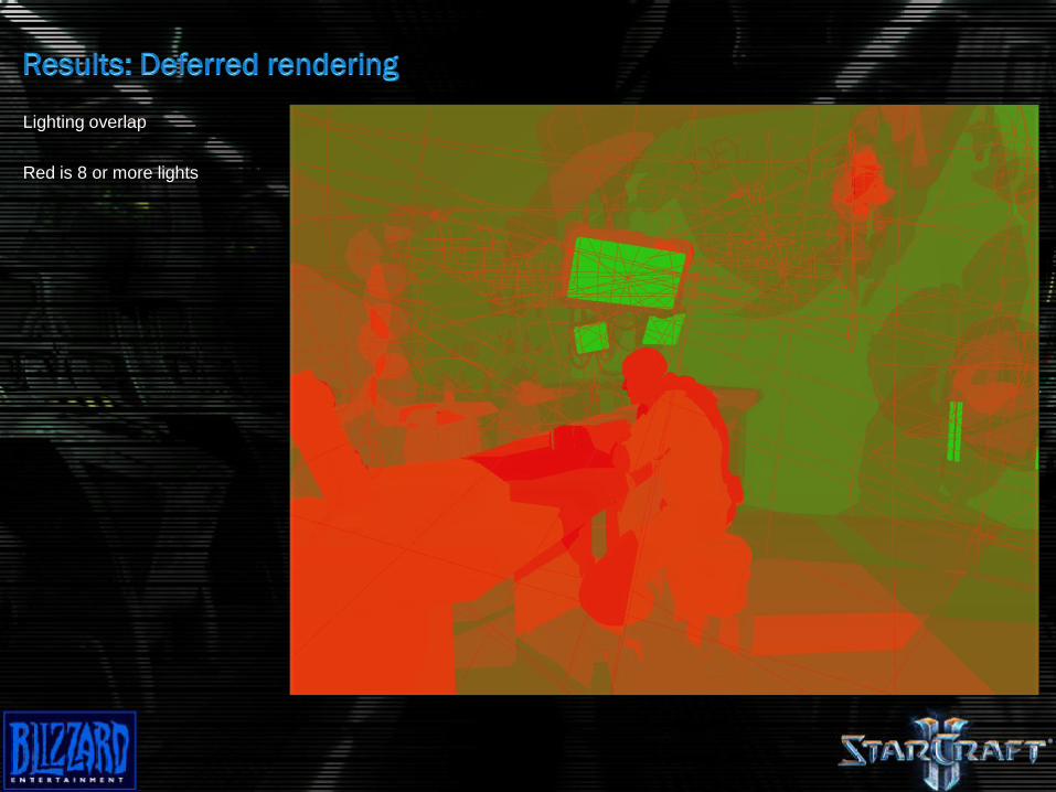
Lighting overlap
Red is 8 or more lights
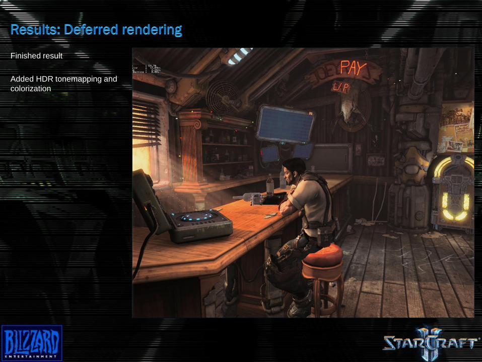
Finished result
Added HDR tonemapping and
colorization
Approximate the occlusion function at points on
visible surfaces by sampling the depth of
neighboring pixels in screen space
Depth map required
Ambient occlusion term will be stored in the
alpha channel so it can modulate the deferred
lighting
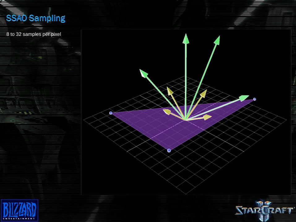
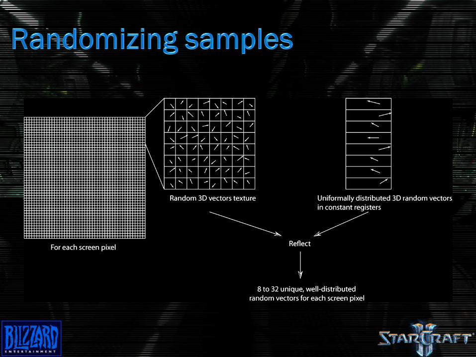
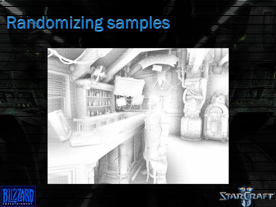
8 to 32 samples per pixel
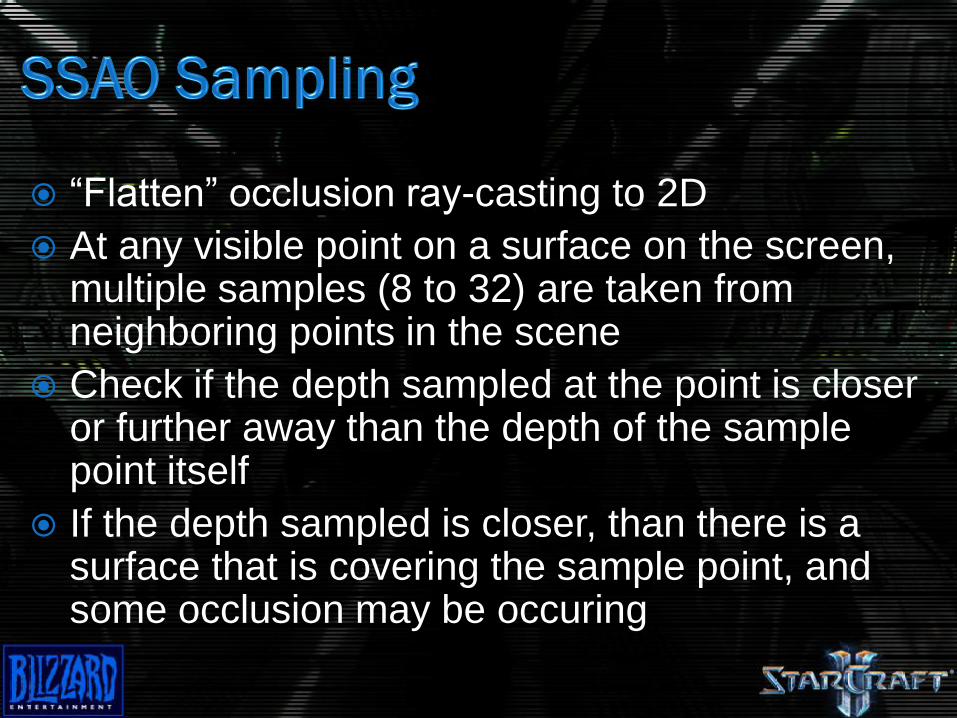
“Flatten” occlusion ray-casting to 2D
At any visible point on a surface on the screen, multiple samples (8 to 32) are taken from neighboring points in the scene
Check if the depth sampled at the point is closer or further away than the depth of the sample point itself
If the depth sampled is closer, than there is a surface that is covering the sample point, and some occlusion may be occuring
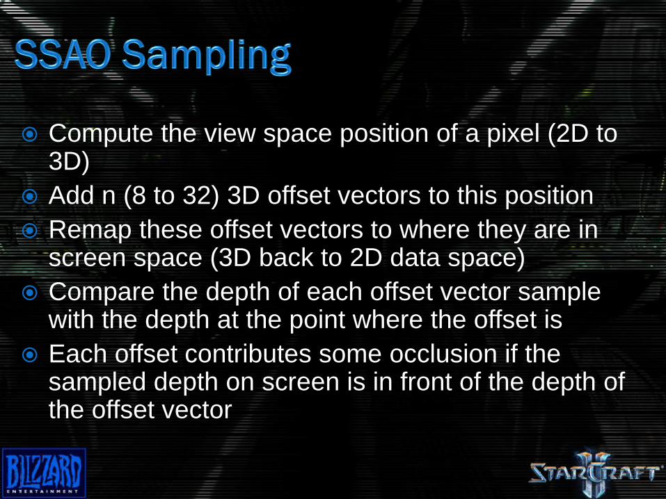
Compute the view space position of a pixel (2D to 3D)
Add n (8 to 32) 3D offset vectors to this position
Remap these offset vectors to where they are in screen space (3D back to 2D data space)
Compare the depth of each offset vector sample with the depth at the point where the offset is
Each offset contributes some occlusion if the sampled depth on screen is in front of the depth of the offset vector
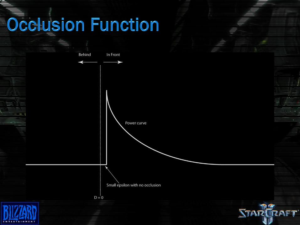
Blockers closer to the sample should occlude
more
Blockers far from the sample don’t occlude at all
Blockers behind don’t occlude at all
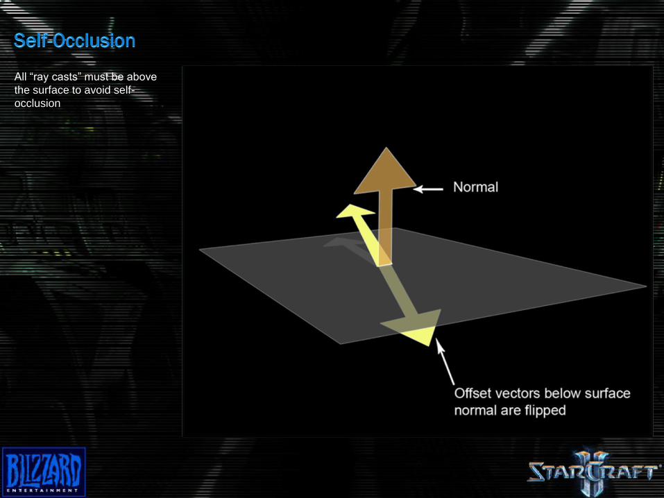
All “ray casts” must be above
the surface to avoid self-
occlusion
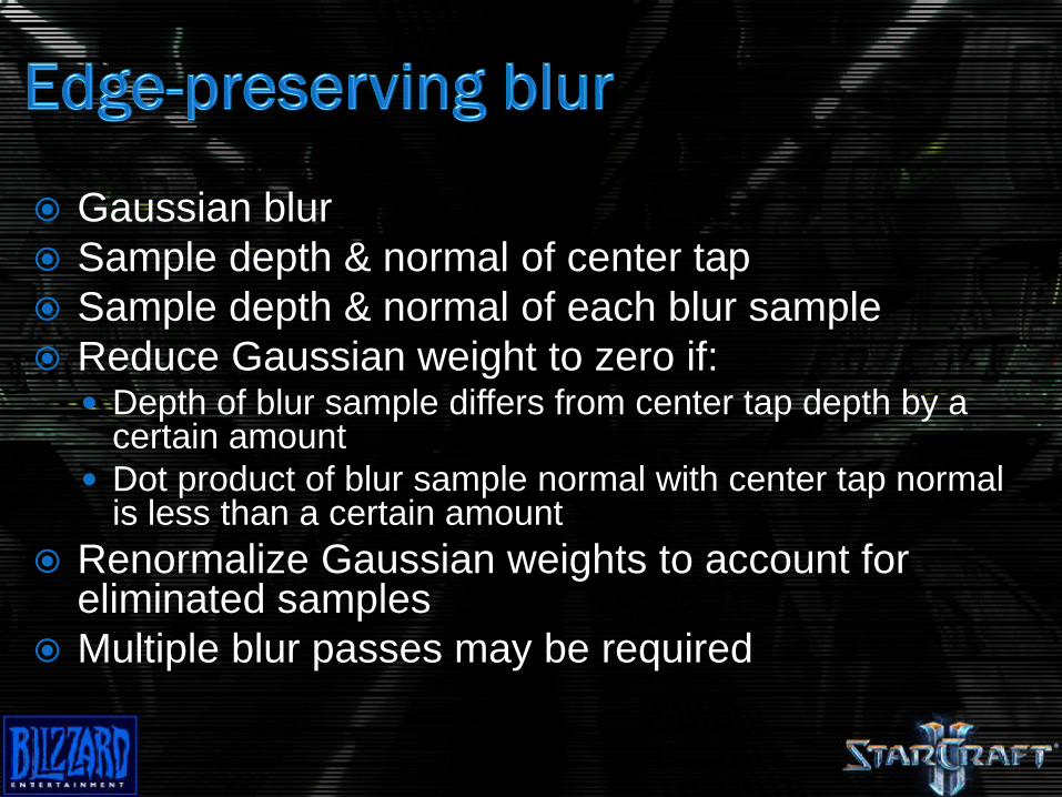
Gaussian blur
Sample depth & normal of center tap
Sample depth & normal of each blur sample
Reduce Gaussian weight to zero if: Depth of blur sample differs from center tap depth by a
certain amount
Dot product of blur sample normal with center tap normal is less than a certain amount
Renormalize Gaussian weights to account for eliminated samples
Multiple blur passes may be required
Offset vector can go outside the screen, where
there is no depth information
Best approximation is ensuring out-of-bounds
samples don’t occlude
Use “Border color” texture wrapping state and
set the “color” to a high depth value
Close-ups lengthen the 3D offset vectors and
cause the SSAO to be under-sampled
Two possible solutions:
Increase sample count dynamically
Limit maximum screen extents of offset vectors
Starcraft II relies on the second approach to
avoid large framerate swings
Texture sampling is a bottleneck
Sampling pattern is not cache-friendly
Wide sampling area makes it worse
Leverage low-frequency aspect
Use a reduced size depth buffer (quarter size)
Wide sampling area creates quasi-GI effect
Distribute samples over two thresholds
One half of samples over wide area for GI
One half of samples over tight area for contrast
and edge enhancement
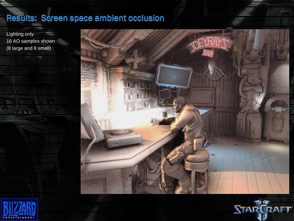
Lighting only
16 AO samples shown
(8 large and 8 small)
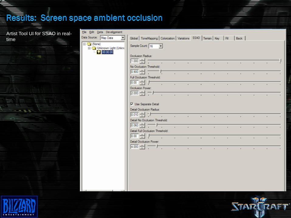
Artist Tool UI for SSAO in real-
time
Lighting only
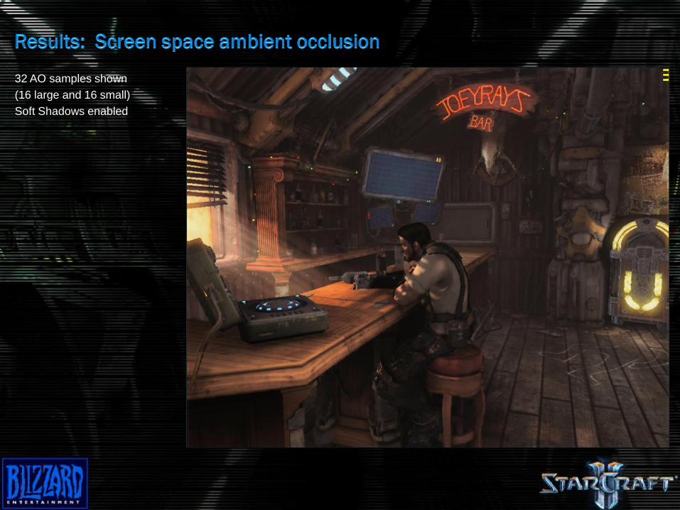
32 AO samples shown
(16 large and 16 small)
Soft Shadows enabled
Video
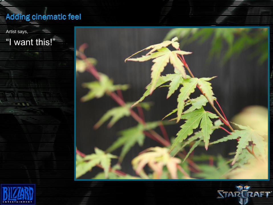
Artist says,
“I want this!”
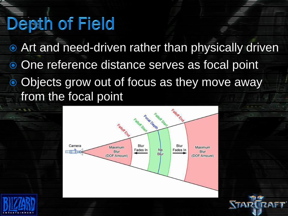
Art and need-driven rather than physically driven
One reference distance serves as focal point
Objects grow out of focus as they move away
from the focal point
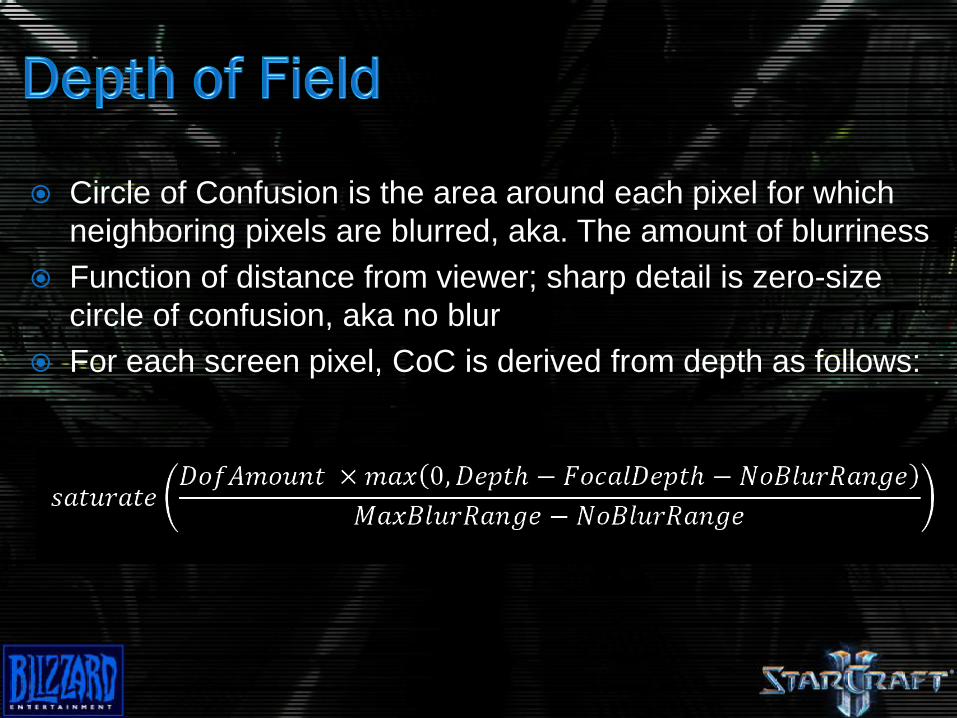
Circle of Confusion is the area around each pixel for which
neighboring pixels are blurred, aka. The amount of blurriness
Function of distance from viewer; sharp detail is zero-size
circle of confusion, aka no blur
For each screen pixel, CoC is derived from depth as follows:
One approach would be to vary the width of the blur kernel
and the amount of blur samples; however, doesn’t scale well
to lower-end hardware
Use three images for different levels of blur and interpolate
between the images to achieve a gradual blur
The lowest-level of blur is no blur, so the source image is a
4th image that will be interpolated at the lower end of the blur
range
Use Gaussian-weighted sampling to generate the blur
images
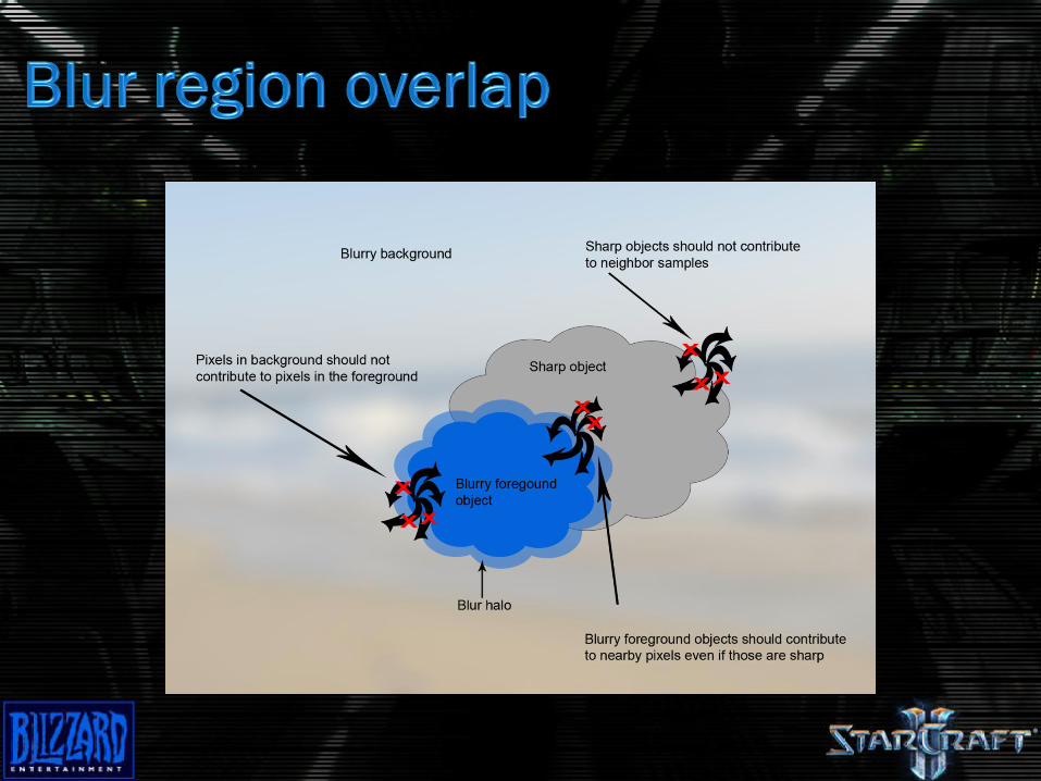
Process works, but needs to handle some
special cases to make the effect believable
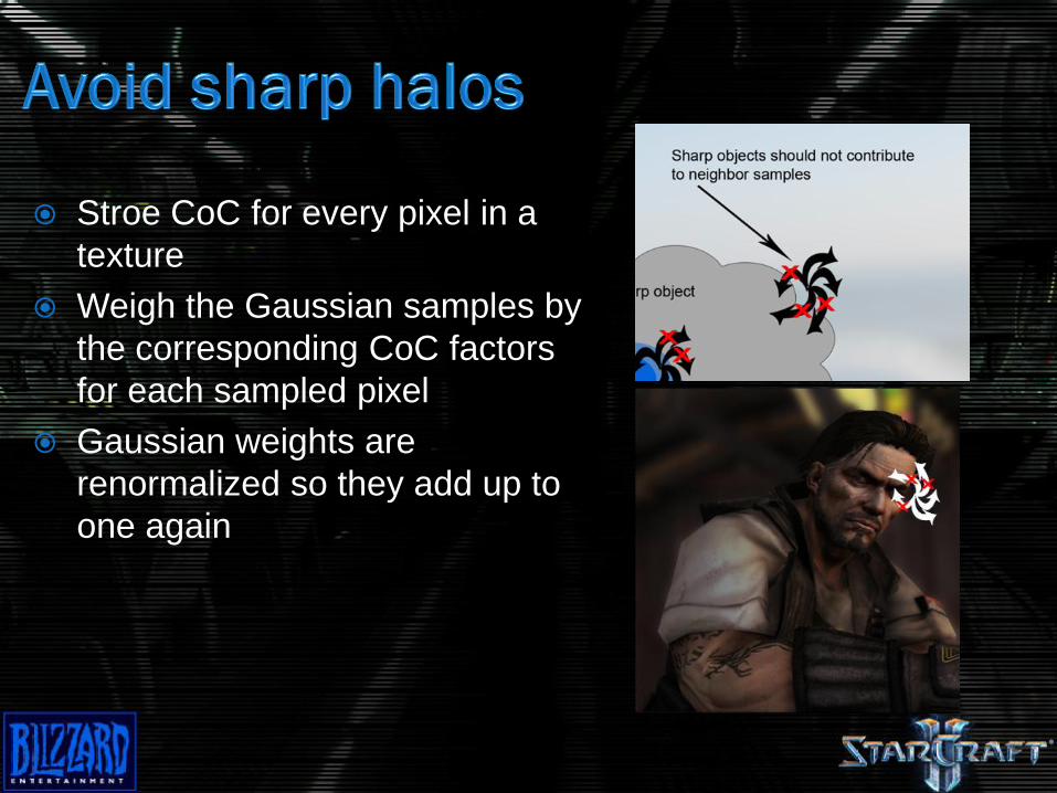
Stroe CoC for every pixel in a
texture
Weigh the Gaussian samples by
the corresponding CoC factors
for each sampled pixel
Gaussian weights are
renormalized so they add up to
one again
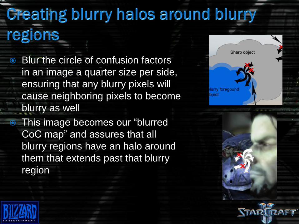
Blur the circle of confusion factors
in an image a quarter size per side,
ensuring that any blurry pixels will
cause neighboring pixels to become
blurry as well
This image becomes our “blurred
CoC map” and assures that all
blurry regions have an halo around
them that extends past that blurry
region
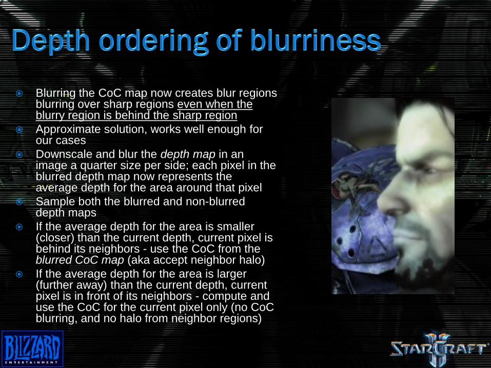
Blurring the CoC map now creates blur regions blurring over sharp regions even when the blurry region is behind the sharp region
Approximate solution, works well enough for our cases
Downscale and blur the depth map in an image a quarter size per side; each pixel in the blurred depth map now represents the average depth for the area around that pixel
Sample both the blurred and non-blurred depth maps
If the average depth for the area is smaller (closer) than the current depth, current pixel is behind its neighbors - use the CoC from the blurred CoC map (aka accept neighbor halo)
If the average depth for the area is larger (further away) than the current depth, current pixel is in front of its neighbors - compute and use the CoC for the current pixel only (no CoC blurring, and no halo from neighbor regions)
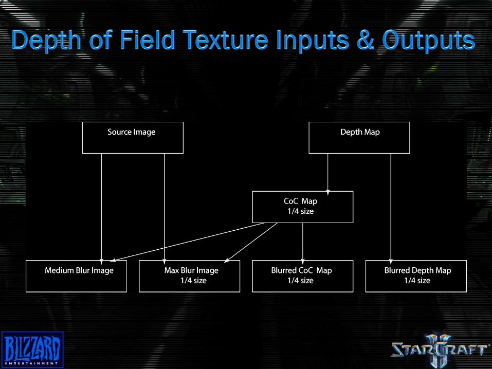
Generate three images for each level of blur
Compute the CoC for each pixel
Generated blurred CoC and depth map
Sample the source depth map and the blurred depth
map and use depth ordering test to determine if the
blurred or non-blurred CoC should be used
Calculate contribution from each of the four blur
sources based on the CoC factor and sum the
contributions
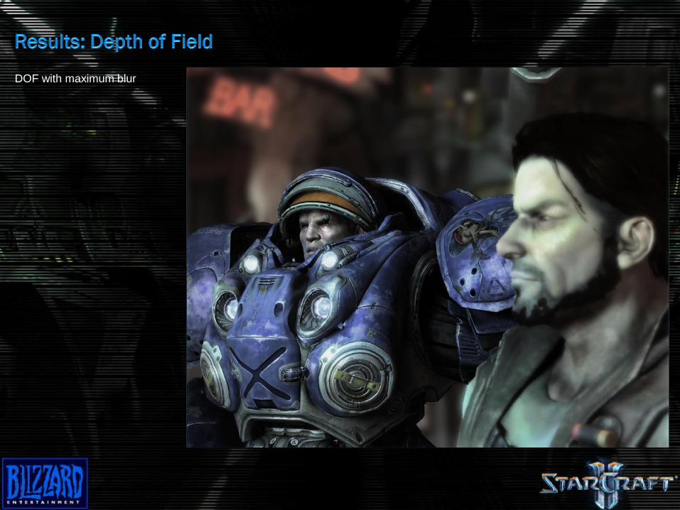
DOF with maximum blur
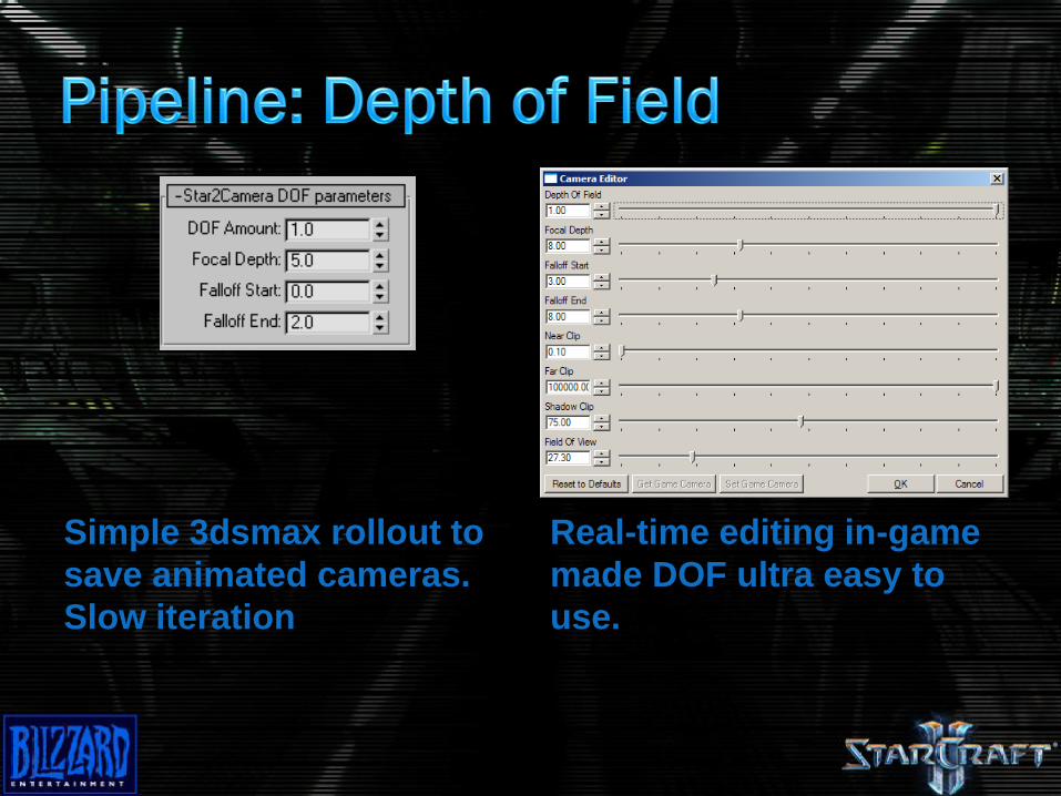
Simple 3dsmax rollout to
save animated cameras.
Slow iteration
Real-time editing in-game
made DOF ultra easy to
use.
Transparencies are… annoying
Only multi-pass lighting is scalable to the lowest-
end hardware
In practice, transparencies are not the point of
focus for our environments
Associating specific transparencies with an
alternate, simpler set of lights is a good
compromise
Depth of field and SSAO can however produce glaring artifacts in a few cases
Need to make compromises
In some cases we will allow transparencies to write the depth map (not the z-buffer)
Although there is still only one depth per pixel, this allows some key transparencies that are only slightly transparencies to handle depth of field and SSAO appropriately
System could be broken down to support n layers but the performance characteristics become extremely variable
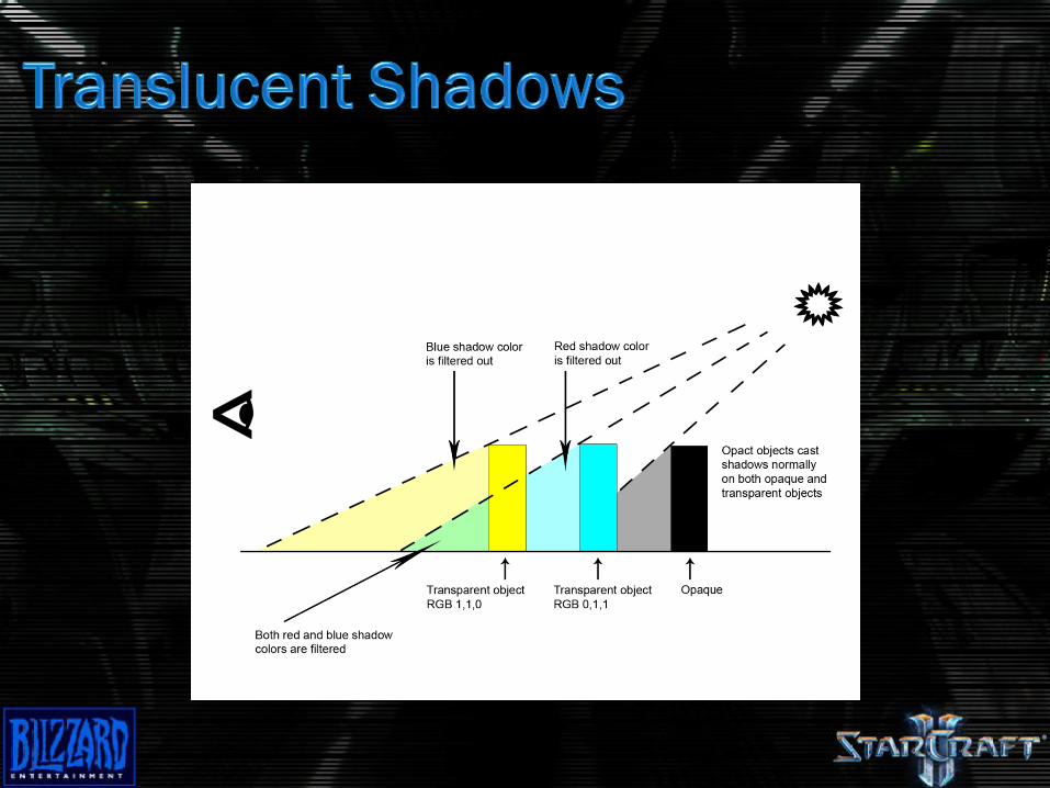
Works seamlessly with regular shadows
Transparent objects set to cats shadows filter
light through them
Use a second shadow map and color buffer
Render first, regular shadow map as normal with
opaque objects
Render transparent shadow-casting objects in
second shadow map
Z-write on
No alpha-test
Less-equal z-test
Records depth of closes transparency
Clear color buffer associated with second shadow map to white
Now render transparent objects again in color buffer
Sort front to back (inverted, these are filters)
Use OPAQUE shadow map as z-buffer
No z-write
Less-equal z-test
Records color information for transparencies in front of opaque objects

Finally, perform shadow test during regular
rendering:
Test both opaque shadow map and translucent
shadow map
If translucent shadow map test fails, modulate by
color of transparent shadow color buffer
Module by result of opaque shadow map test (binary
test)
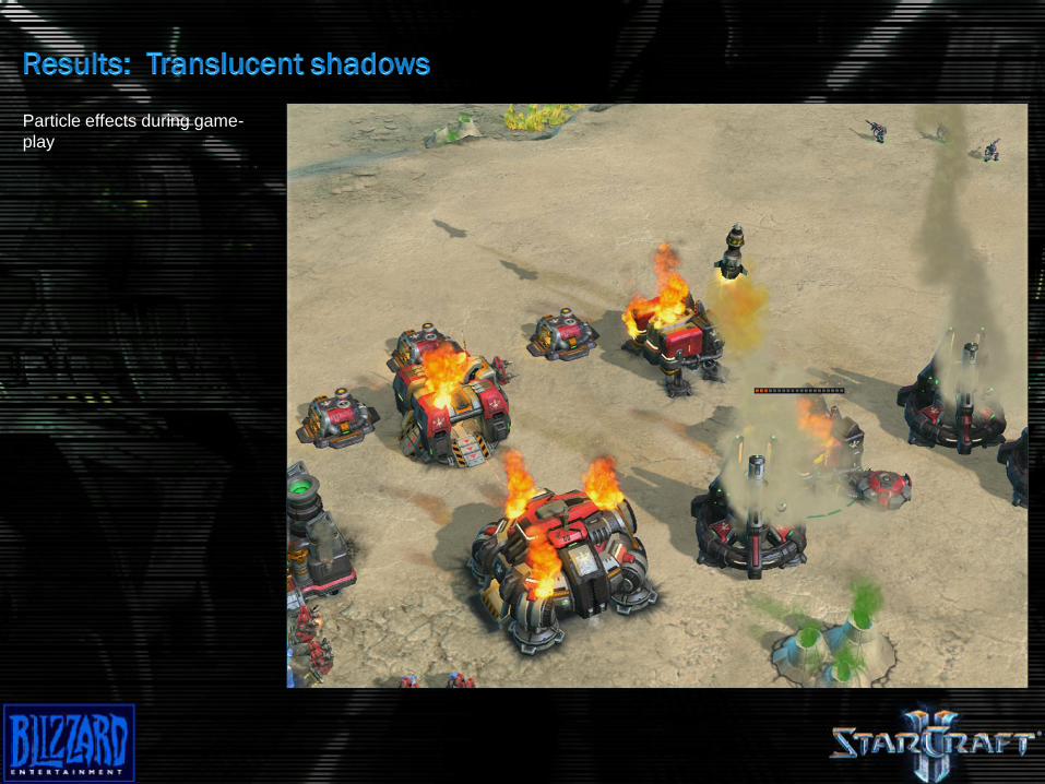
Particle effects during game-
play
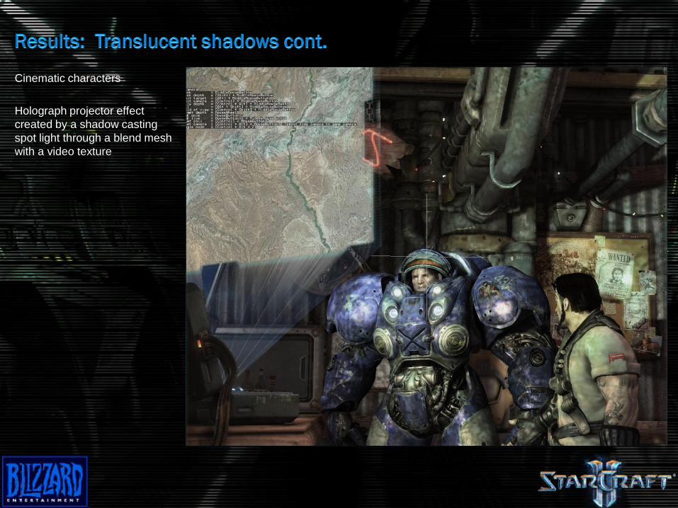
Cinematic characters
Holograph projector effect
created by a shadow casting
spot light through a blend mesh
with a video texture
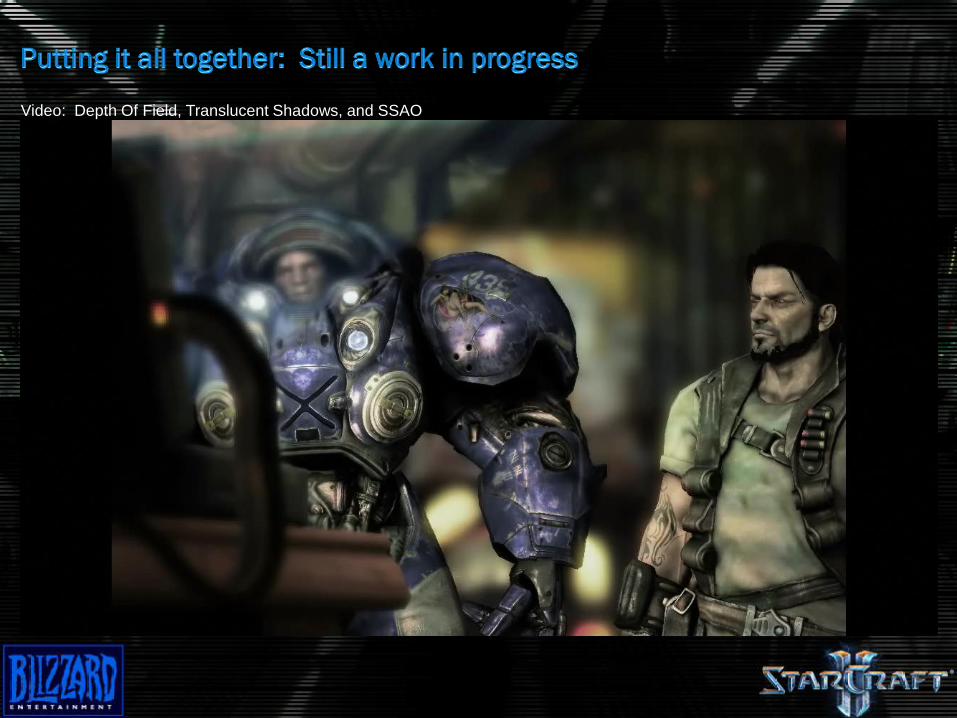
Video: Depth Of Field, Translucent Shadows, and SSAO

Thinking in screen-space:
Allows many interesting effects if approximations are
acceptable
Simplifies existing rendering processes
Tends to have reliable, consistent performance

Check out www.blizzard.com for details
Tools programmers go to the front of the line!