donald r . solution
TRANSCRIPT
1
1Introduction to Materials Science and Engineering
1–4 Steel is often coated with a thin layer of zinc if it is to be used outside. What charac-teristics do you think the zinc provides to this coated, or galvanized, steel? Whatprecautions should be considered in producing this product? How will the recycla-bility of the product be affected?
Solution: The zinc provides corrosion resistance to the iron in two ways. If theiron is completely coated with zinc, the zinc provides a barrier betweenthe iron and the surrounding environment, therefore protecting theunderlying iron. If the zinc coating is scratched to expose the iron, thezinc continues to protect the iron because the zinc corrodes preferentiallyto the iron (see Chapter 23). To be effective, the zinc should bond well tothe iron so that it does not permit reactions to occur at the interface withthe iron and so that the zinc remains intact during any forming of thegalvanized material. When the material is recycled, the zinc will be lostby oxidation and vaporization, often producing a “zinc dust” that maypose an environmental hazard. Special equipment may be required tocollect and either recycle or dispose of the zinc dust.
1–5 We would like to produce a transparent canopy for an aircraft. If we were to use aceramic (that is, traditional window glass) canopy, rocks or birds might cause it toshatter. Design a material that would minimize damage or at least keep the canopyfrom breaking into pieces.
Solution: We might sandwich a thin sheet of a transparent polymer between twolayers of the glass. This approach, used for windshields of automobiles,will prevent the “safety” glass from completely disintegrating when it
01 Askeland Chap 9/27/05 1:48 PM Page 1
fails, with the polymer holding the broken pieces of glass together untilthe canopy can be replaced.
Another approach might be to use a transparent, “glassy” polymermaterial such as polycarbonate. Some polymers have reasonably goodimpact properties and may resist failure. The polymers can also betoughened to resist impact by introducing tiny globules of a rubber,or elastomer, into the polymer; these globules improve the energy-absorbing ability of the composite polymer, while being toosmall to interfere with the optical properties of the material.
1–6 Coiled springs ought to be very strong and stiff. Si3N4 is a strong, stiff material.Would you select this material for a spring? Explain.
Solution: Springs are intended to resist high elastic forces, where only the atomicbonds are stretched when the force is applied. The silicon nitride wouldsatisfy this requirement. However, we would like to also have goodresistance to impact and at least some ductility (in case the spring isoverloaded) to assure that the spring will not fail catastrophically. Wealso would like to be sure that all springs will perform satisfactorily.Ceramic materials such as silicon nitride have virtually no ductility,poor impact properties, and often are difficult to manufacture withoutintroducing at least some small flaws that cause to fail even for relativelylow forces. The silicon nitride is NOT recommended.
1–7 Temperature indicators are sometimes produced from a coiled metal strip thatuncoils a specific amount when the temperature increases. How does this work;from what kind of material would the indicator be made; and what are the importantproperties that the material in the indicator must possess?
Solution: Bimetallic materials are produced by bonding two materials havingdifferent coefficients of thermal expansion to one another, forming alaminar composite. When the temperature changes, one of the materialswill expand or contract more than the other material. This difference inexpansion or contraction causes the bimetallic material to change shape;if the original shape is that of a coil, then the device will coil or uncoil,depending on the direction of the temperature change. In order for thematerial to perform well, the two materials must have very differentcoefficients of thermal expansion and should have high enough modulusof elasticity so that no permanent deformation of the material occurs.
1–8 You would like to design an aircraft that can be flown by human power nonstop fora distance of 30 km. What types of material properties would you recommend?What materials might be appropriate?
Solution: Such an aircraft must possess enough strength and stiffness to resist its own weight, the weight of the human “power source”, and anyaerodynamic forces imposed on it. On the other hand, it must be as lightas possible to assure that the human can generate enough work tooperate the aircraft. Composite materials, particularly those based on apolymer matrix, might comprise the bulk of the aircraft. The polymershave a light weight (with densities of less than half that of aluminum)and can be strengthened by introducing strong, stiff fibers made of glass,carbon, or other polymers. Composites having the strength and stiffness
2 The Science and Engineering of Materials Instructor’s Solutions Manual
01 Askeland Chap 9/27/05 1:48 PM Page 2
of steel, but with only a fraction of the weight, can be produced in thismanner.
1–9 You would like to place a three-foot diameter microsatellite into orbit. The satellitewill contain delicate electronic equipment that will send and receive radio signals fromearth. Design the outer shell within which the electronic equipment is contained. Whatproperties will be required, and what kind of materials might be considered?
Solution: The shell of the microsatellite must satisfy several criteria. The materialshould have a low density, minimizing the satellite weight so that it canbe lifted economically into its orbit; the material must be strong, hard,and impact resistant in order to assure that any “space dust” that mightstrike the satellite does not penetrate and damage the electronicequipment; the material must be transparent to the radio signals thatprovide communication between the satellite and earth; and the materialmust provide some thermal insulation to assure that solar heating doesnot damage the electronics.
One approach might be to use a composite shell of several materials.The outside surface might be a very thin reflective metal coating thatwould help reflect solar heat. The main body of the shell might be a lightweight fiber-reinforced composite that would provide impact resistance(preventing penetration by dust particles) but would be transparent toradio signals.
1–10 What properties should the head of a carpenter’s hammer possess? How would youmanufacture a hammer head?
Solution: The head for a carpenter’s hammer is produced by forging, a metal-working process; a simple steel shape is heated and formed in severalsteps while hot into the required shape. The head is then heat treated toproduce the required mechanical and physical properties.
The striking face and claws of the hammer should be hard—the metalshould not dent or deform when driving or removing nails. Yet theseportions must also possess some impact resistance, particularly so thatchips do not flake off the striking face and cause injuries.
1–11 The hull of the space shuttle consists of ceramic tiles bonded to an aluminum skin.Discuss the design requirements of the shuttle hull that led to the use of this combi-nation of materials. What problems in producing the hull might the designers andmanufacturers have faced?
Solution: The space shuttle experiences extreme temperatures during re-entry intoearth’s atmosphere; consequently a thermal protection system must beused to prevent damage to the structure of the shuttle (not to mention itscontents!). The skin must therefore be composed of a material that hasan exceptionally low thermal conductivity. The material must be capableof being firmly attached to the skin of the shuttle and to be easilyrepaired when damage occurs.
The tiles used on the space shuttle are composed of silica fibers bondedtogether to produce a very low density ceramic. The thermalconductivity is so low that a person can hold on to one side of the tilewhile the opposite surface is red hot. The tiles are attached to the shuttle
CHAPTER 1 Introduction to Materials Science and Engineering 3
01 Askeland Chap 9/27/05 1:48 PM Page 3
skin using a rubbery polymer that helps assure that the forces do notbreak the tile loose, which would then expose the underlying skin tohigh temperatures.
1–12 You would like to select a material for the electrical contacts in an electrical switch-ing device which opens and closes frequently and forcefully. What properties shouldthe contact material possess? What type of material might you recommend? WouldAl2O3 be a good choice? Explain.
Solution: The material must have a high electrical conductivity to assure that noelectrical heating or arcing occurs when the switch is closed. High purity(and therefore very soft) metals such as copper, aluminum, silver or goldprovide the high conductivity. However, the device must also have goodwear resistance, requiring that the material be hard. Most hard, wearresistant materials have poor electrical conductivity.
One solution to this problem is to produce a particulate compositematerial composed of hard ceramic particles embedded in a continuousmatrix of the electrical conductor. For example, silicon carbide particlescould be introduced into pure aluminum; the silicon carbide particlesprovide wear resistance while aluminum provides conductivity. Otherexamples of these materials are described in Chapter 17.
Al2O3 by itself would not be a good choice—alumina is a ceramicmaterial and is an electrical insulator. However, alumina particlesdispersed into a copper matrix might provide wear resistance to thecomposite.
1–13 Aluminum has a density of 2.7 g/cm3. Suppose you would like to produce a com-posite material based on aluminum having a density of 1.5 g/cm3. Design a materialthat would have this density. Would introducing beads of polyethylene, with a density of 0.95 g/cm3, into the aluminum be a likely possibility? Explain.
Solution: In order to produce an aluminum-matrix composite material with adensity of 1.5 g/cm3, we would need to select a material having adensity considerably less than 1.5 g/cm3. While polyethylene’s densitywould make it a possibility, the polyethylene has a very low meltingpoint compared to aluminum; this would make it very difficult tointroduce the polyethylene into a solid aluminum matrix—processessuch as casting or powder metallurgy would destroy the polyethylene.Therefore polyethylene would NOT be a likely possibility.
One approach, however, might be to introduce hollow glass beads.Although ceramic glasses have densities comparable to that ofaluminum, a hollow bead will have a very low density. The glass alsohas a high melting temperature and could be introduced into liquidaluminum for processing as a casting.
1–14 You would like to be able to identify different materials without resorting to chemicalanalysis or lengthy testing procedures. Describe some possible testing and sortingtechniques you might be able to use based on the physical properties of materials.
Solution: Some typical methods might include: measuring the density of thematerial (may help in separating metal groups such as aluminum,copper, steel, magnesium, etc.), determining the electrical conductivity
4 The Science and Engineering of Materials Instructor’s Solutions Manual
01 Askeland Chap 9/27/05 1:48 PM Page 4

of the material (may help in separating ceramics and polymers frommetallic alloys), measuring the hardness of the material (perhaps evenjust using a file), and determining whether the material is magnetic ornonmagnetic (may help separate iron from other metallic alloys).
1–15 You would like to be able to physically separate different materials in a scrap recy-cling plant. Describe some possible methods that might be used to separate materi-als such as polymers, aluminum alloys, and steels from one another.
Solution: Steels can be magnetically separated from the other materials; steel (orcarbon-containing iron alloys) are ferromagnetic and will be attracted bymagnets. Density differences could be used—polymers have a densitynear that of water; the specific gravity of aluminum alloys is around 2.7;that of steels is between 7.5 and 8. Electrical conductivity measurementscould be used—polymers are insulators, aluminum has a particularlyhigh electrical conductivity.
1–16 Some pistons for automobile engines might be produced from a composite materialcontaining small, hard silicon carbide particles in an aluminum alloy matrix. Explainwhat benefits each material in the composite may provide to the overall part. Whatproblems might the different properties of the two materials cause in producing the part?
Solution: Aluminum provides good heat transfer due to its high thermalconductivity. It has good ductility and toughness, reasonably goodstrength, and is easy to cast and process. The silicon carbide, a ceramic,is hard and strong, providing good wear resistance, and also has a highmelting temperature. It provides good strength to the aluminum, even atelevated temperatures. However there may be problems producing thematerial—for example, the silicon carbide may not be uniformlydistributed in the aluminum matrix if the pistons are produced bycasting. We need to assure good bonding between the particles and thealuminum—the surface chemistry must therefore be understood.Differences in expansion and contraction with temperature changes maycause debonding and even cracking in the composite.
CHAPTER 1 Introduction to Materials Science and Engineering 5
01 Askeland Chap 9/27/05 1:48 PM Page 5

01 Askeland Chap 9/27/05 1:48 PM Page 6
7
2Atomic Structure
2–6 (a) Aluminum foil used for storing food weighs about 0.3 g per square inch. Howmany atoms of aluminum are contained in one square inch of foil?
Solution: In a one square inch sample:
number =(0.3 g)(6.02 × 10²³ atoms/mol)
= 6.69 × 10²¹ atoms26.981 g/mol
(b) Using the densities and atomic weights given in Appendix A, calculate and com-pare the number of atoms per cubic centimeter in (i) lead and (ii) lithium.
Solution: (i) In lead:
(11.36 g/cm3)(1 cm3)(6.02 × 10²³ atoms/mol)= 3.3 × 10²² atoms/cm3
207.19 g/mol
(ii) In lithium:
(0.534 g/cm3)(1 cm3)(6.02 × 10²³ atoms/mol)= 4.63 × 10²² atoms/cm3
6.94 g/mol
2–7 (a) Using data in Appendix A, calculate the number of iron atoms in one ton (2000pounds).
Solution: (2000 lb)(454 g/lb)(6.02 × 1023 atoms/mol)= 9.79 × 1027 atoms/ton
55.847 g/mol
(b) Using data in Appendix A, calculate the volume in cubic centimeters occupied byone mole of boron.
Solution: (1 mol)(10.81 g/mol)= 4.7 cm3
2.3 g/cm3
02 Askeland Chap 9/27/05 1:49 PM Page 7
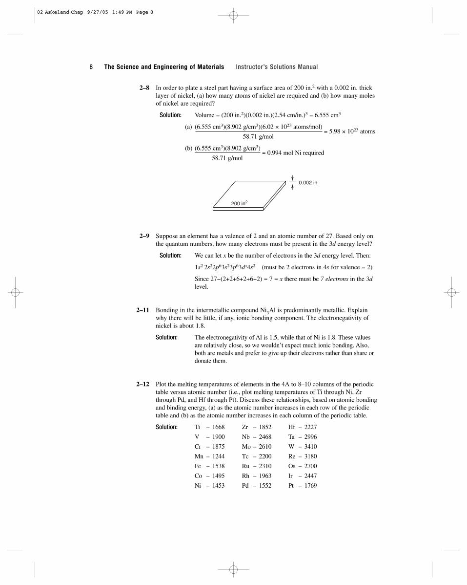
2–8 In order to plate a steel part having a surface area of 200 in.2 with a 0.002 in. thicklayer of nickel, (a) how many atoms of nickel are required and (b) how many molesof nickel are required?
Solution: Volume = (200 in.2)(0.002 in.)(2.54 cm/in.)3 = 6.555 cm3
(a) (6.555 cm3)(8.902 g/cm3)(6.02 × 1023 atoms/mol)= 5.98 × 10²³ atoms
58.71 g/mol
(b) (6.555 cm3)(8.902 g/cm3)= 0.994 mol Ni required
58.71 g/mol
2–9 Suppose an element has a valence of 2 and an atomic number of 27. Based only onthe quantum numbers, how many electrons must be present in the 3d energy level?
Solution: We can let x be the number of electrons in the 3d energy level. Then:
1s2 2s22p63s23p63dx4s2 (must be 2 electrons in 4s for valence = 2)
Since 27−(2+2+6+2+6+2) = 7 = x there must be 7 electrons in the 3dlevel.
2–11 Bonding in the intermetallic compound Ni3Al is predominantly metallic. Explainwhy there will be little, if any, ionic bonding component. The electronegativity ofnickel is about 1.8.
Solution: The electronegativity of Al is 1.5, while that of Ni is 1.8. These valuesare relatively close, so we wouldn’t expect much ionic bonding. Also,both are metals and prefer to give up their electrons rather than share ordonate them.
2–12 Plot the melting temperatures of elements in the 4A to 8–10 columns of the periodictable versus atomic number (i.e., plot melting temperatures of Ti through Ni, Zrthrough Pd, and Hf through Pt). Discuss these relationships, based on atomic bondingand binding energy, (a) as the atomic number increases in each row of the periodictable and (b) as the atomic number increases in each column of the periodic table.
Solution: Ti – 1668 Zr – 1852 Hf – 2227
V – 1900 Nb – 2468 Ta – 2996
Cr – 1875 Mo – 2610 W – 3410
Mn – 1244 Tc – 2200 Re – 3180
Fe – 1538 Ru – 2310 Os – 2700
Co – 1495 Rh – 1963 Ir – 2447
Ni – 1453 Pd – 1552 Pt – 1769
200 in2
0.002 in
8 The Science and Engineering of Materials Instructor’s Solutions Manual
02 Askeland Chap 9/27/05 1:49 PM Page 8
For each row, the melting temperature is highest when the outer “d”energy level is partly full. In Cr, there are 5 electrons in the 3d shell;in Mo, there are 5 electrons in the 4d shell; in W there are 4 electronsin the 5d shell. In each column, the melting temperature increases asthe atomic number increases—the atom cores contain a larger num-ber of tightly held electrons, making the metals more stable.
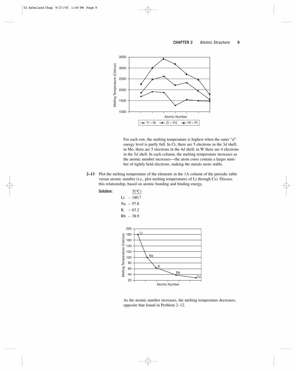
2–13 Plot the melting temperature of the elements in the 1A column of the periodic tableversus atomic number (i.e., plot melting temperatures of Li through Cs). Discussthis relationship, based on atomic bonding and binding energy.
Solution: T(oC)
Li – 180.7
Na – 97.8
K – 63.2
Rb – 38.9
Cs – 28.6
As the atomic number increases, the melting temperature decreases,opposite that found in Problem 2–12.
Atomic Number20
40
60
80
100
120
140
160
180
200Li
Na
K
RbCsM
eltin
g Te
mpe
ratu
re (
Cel
cius
)
Atomic Number
3500
3000
2500
2000
1500
1000
Ti – Ni Zr – Pd Hf – Pt
Mel
ting
Tem
pera
ture
(C
elci
us)
CHAPTER 2 Atomic Structure 9
02 Askeland Chap 9/27/05 1:49 PM Page 9

2–14 Calculate the fraction of bonding of MgO that is ionic.
Solution: EMg = 1.2 EO = 3.5
fcovalent = exp[(−0.25)(3.5 − 1.2)2] = exp(−1.3225) = 0.266
fionic = 1 − 0.266 = 0.734 ∴ bonding is mostly ionic
2–18 Beryllium and magnesium, both in the 2A column of the periodic table, are light-weight metals. Which would you expect to have the higher modulus of elasticity?Explain, considering binding energy and atom radii and using appropriate sketchesof force versus interatomic spacing.
Solution: 4 Be 1s22s2 E = 42 × 106 psi rBe = 1.143 Å
12 Mg 1s22s22p63s2 E = 6 × 10⁶ psi rMg = 1.604 Å
The smaller Be electrons are held closer to the core ∴ held more tightly,giving a higher binding energy.
2–19 Would you expect MgO or magnesium to have the higher modulus of elasticity?Explain.
Solution: MgO has ionic bonds, which are strong compared to the metallic bondsin Mg. A higher force will be required to cause the same separationbetween the ions in MgO compared to the atoms in Mg. Therefore, MgOshould have the higher modulus of elasticity. In Mg, E ≈ 6 × 10⁶ psi; inMgO, E = 30 × 106 psi.
2–20 Aluminum and silicon are side-by-side in the periodic table. Which would youexpect to have the higher modulus of elasticity (E)? Explain.
Solution: Silicon has covalent bonds; aluminum has metallic bonds. Therefore,Si should have a higher modulus of elasticity.
2–21 Steel is coated with a thin layer of ceramic to help protect against corrosion. Whatdo you expect to happen to the coating when the temperature of the steel isincreased significantly? Explain.
Solution: Ceramics are expected to have a low coefficient of thermal expansiondue to strong ionic/covalent bonds; steel has a high thermal expansioncoefficient. When the structure heats, steel expands more than the coat-ing, which may crack and expose the underlying steel to corrosion.
For
ce
EBe ~ ∆f /∆a
Be
Mg
EMg ~ ∆f /∆a
distance “a”2rBe
2rmg
10 The Science and Engineering of Materials Instructor’s Solutions Manual
02 Askeland Chap 9/27/05 1:49 PM Page 10
11
3Atomic and Ionic Arrangements
3–13 Calculate the atomic radius in cm for the following: (a) BCC metal with a0 = 0.3294 nm and one atom per lattice point; and (b) FCC metal with a0 = 4.0862 Å and one atom per lattice point.
Solution: (a) For BCC metals,
(b) For FCC metals,
3–14 Determine the crystal structure for the following: (a) a metal with a0 = 4.9489 Å,r = 1.75 Å and one atom per lattice point; and (b) a metal with a0 = 0.42906 nm,r = 0.1858 nm and one atom per lattice point.
Solution: We want to determine if “x” in the calculations below equals (for FCC) or (for BCC):
(a) (x)(4.9489 Å) = (4)(1.75 Å)
x = , therefore FCC
(b) (x)(0.42906 nm) = (4)(0.1858 nm)
x = , therefore BCC
3–15 The density of potassium, which has the BCC structure and one atom per latticepoint, is 0.855 g/cm3. The atomic weight of potassium is 39.09 g/mol. Calculate (a) the lattice parameter; and (b) the atomic radius of potassium.
3
2
32
ra
=2
=2 ( .0862 Å)
4= . 447 Å = . 447 10 cm8( ) ( )
× −0
4
41 4 1 4
ra
=3
=3 ( . nm)
4= . 426 nm = .426 10 cm8( ) ( )
× −0
4
0 32940 1 1
03 Askeland Chap 9/27/05 11:34 AM Page 11

Solution: (a) Using Equation 3–5:
0.855 g/cm3 =(2 atoms/cell)(39.09 g/mol)
(a0)3(6.02 × 10²³ atoms/mol)
a03 = 1.5189 × 10⁻²² cm3 or a0 = 5.3355 × 10⁻⁸ cm
(b) From the relationship between atomic radius and lattice parameter:
3–16 The density of thorium, which has the FCC structure and one atom per lattice point,is 11.72 g/cm3. The atomic weight of thorium is 232 g/mol. Calculate (a) the latticeparameter and (b) the atomic radius of thorium.
Solution: (a) From Equation 3–5:
11.72 g/cm3 =(4 atoms/cell)(232 g/mol)
(a0)3(6.02 × 10²³ atoms/mol)
a03 = 1.315297 × 10⁻²² cm3 or a0 = 5.0856 × 10⁻⁸ cm
(b) From the relationship between atomic radius and lattice parameter:
3–17 A metal having a cubic structure has a density of 2.6 g/cm3, an atomic weight of 87.62 g/mol, and a lattice parameter of 6.0849 Å. One atom is associated with eachlattice point. Determine the crystal structure of the metal.
Solution: 2.6 g/cm3 =(x atoms/cell)(87.62 g/mol)
(6.0849 × 10⁻⁸ cm)3(6.02 × 10²³ atoms/mol)
x = 4, therefore FCC
3–18 A metal having a cubic structure has a density of 1.892 g/cm3, an atomic weight of132.91 g/mol, and a lattice parameter of 6.13 Å. One atom is associated with eachlattice point. Determine the crystal structure of the metal.
Solution: 1.892 g/cm3 = (x atoms/cell)(132.91 g/mol)
(6.13 × 10⁻⁸ cm)3(6.02 × 10²³ atoms/mol)
x = 2, therefore BCC
3–19 Indium has a tetragonal structure with a0 = 0.32517 nm and c0 = 0.49459 nm. Thedensity is 7.286 g/cm3 and the atomic weight is 114.82 g/mol. Does indium have the simple tetragonal or body-centered tetragonal structure?
Solution:
7.286 g/cm3 =(x atoms/cell)(114.82 g/mol)
(3.2517 × 10⁻⁸ cm)2(4.9459 × 10⁻⁸ cm)(6.02 × 10²³ atoms/mol)
x = 2, therefore BCT (body-centered tetragonal)
r =×
= ×−
−( )( . ).
2 5 0856 10
41 7980 10
88 cm cm
r =×
= ×−
−( )( . ).
2 5 0856 10
41 7980 10
88 cm cm
12 The Science and Engineering of Materials Instructor’s Solutions Manual
× −.2 3103 10 8 cm33553
03 Askeland Chap 9/27/05 11:34 AM Page 12

3–20 Bismuth has a hexagonal structure, with a0 = 0.4546 nm and c0 = 1.186 nm. The density is 9.808 g/cm3 and the atomic weight is 208.98 g/mol. Determine (a) the volume of the unit cell and (b) the number of atoms in each unit cell.
Solution: (a) The volume of the unit cell is V = a02c0cos30.
V = (0.4546 nm)2(1.186 nm)(cos30) = 0.21226 nm3
= 2.1226 × 10⁻²² cm3
(b) If “x” is the number of atoms per unit cell, then:
9.808 g/cm3 =(x atoms/cell)(208.98 g/mol)
(2.1226 × 10⁻²² cm3)(6.02 × 10²³ atoms/mol)
x = 6 atoms/cell
3–21 Gallium has an orthorhombic structure, with a0 = 0.45258 nm, b0 = 0.45186 nm,and c0 = 0.76570 nm. The atomic radius is 0.1218 nm. The density is 5.904 g/cm3
and the atomic weight is 69.72 g/mol. Determine (a) the number of atoms in eachunit cell and (b) the packing factor in the unit cell.
Solution: The volume of the unit cell is V = a0b0c0 or
V = (0.45258 nm)(0.45186 nm)(0.76570 nm) = 0.1566 nm3
= 1.566 × 10⁻²² cm3
(a) From the density equation:
5.904 g/cm3 =(x atoms/cell)(69.72 g/mol)
(1.566 × 10⁻²² cm3)(6.02 × 10²³ atoms/mol)
x = 8 atoms/cell
(b) From the packing factor (PF) equation:
PF =(8 atoms/cell)(4π/3)(0.1218 nm)3
= 0.3870.1566 nm3
3–22 Beryllium has a hexagonal crystal structure, with a0 = 0.22858 nm and c0 = 0.35842 nm. The atomic radius is 0.1143 nm, the density is 1.848 g/cm3,and the atomic weight is 9.01 g/mol. Determine (a) the number of atoms in eachunit cell and (b) the packing factor in the unit cell.
Solution: V = (0.22858 nm)2(0.35842 nm)cos 30 = 0.01622 nm3 = 16.22 × 10⁻²⁴ cm3
(a) From the density equation:
1.848 g/cm3 =(x atoms/cell)(9.01 g/mol)
(16.22 × 10⁻²⁴ cm3)(6.02 × 10²³ atoms/mol)
x = 2 atoms/cell
(b) The packing factor (PF) is:
PF =(2 atoms/cell)(4π/3)(0.1143 nm)3
= 0.770.01622 nm3
CHAPTER 3 Atomic and Ionic Arrangements 13
03 Askeland Chap 9/27/05 11:34 AM Page 13
3–23 A typical paper clip weighs 0.59 g and consists of BCC iron. Calculate (a) the num-ber of unit cells and (b) the number of iron atoms in the paper clip. (See Appendix Afor required data)
Solution: The lattice parameter for BCC iron is 2.866 × 10⁻⁸ cm. Therefore
Vunit cell = (2.866 × 10⁻⁸ cm)3 = 2.354 × 10⁻²³ cm3
(a) The density is 7.87 g/cm3. The number of unit cells is:
number =0.59 g
= 3.185 × 10²¹ cells(7.87 g/cm3)(2.354 × 10−23 cm3/cell)
(b) There are 2 atoms/cell in BCC iron. The number of atoms is:
number = (3.185 × 10²¹ cells)(2 atoms/cell) = 6.37 × 10²¹ atoms
3–24 Aluminum foil used to package food is approximately 0.001 inch thick. Assume thatall of the unit cells of the aluminum are arranged so that a0 is perpendicular to thefoil surface. For a 4 in. × 4 in. square of the foil, determine (a) the total number ofunit cells in the foil and (b) the thickness of the foil in number of unit cells. (SeeAppendix A.)
Solution: The lattice parameter for aluminum is 4.04958 × 10⁻⁸ cm. Therefore:
Vunit cell = (4.04958 × 10⁻⁸)3 = 6.6409 × 10⁻²³ cm3
The volume of the foil is:
Vfoil = (4 in.)(4 in.)(0.001 in.) = 0.016 in.3 = 0.262 cm3
(a) The number of unit cells in the foil is:
number =0.262 cm3
= 3.945 × 10²¹ cells6.6409 × 10−23 cm3/cell
(b) The thickness of the foil, in number of unit cells, is:
number =(0.001 in.)(2.54 cm/in.)
= 6.27 × 10⁴ cells4.04958 × 10−8 cm
3–27 Above 882oC, titanium has a BCC crystal structure, with a = 0.332 nm. Below thistemperature, titanium has a HCP structure, with a = 0.2978 nm and c = 0.4735 nm.Determine the percent volume change when BCC titanium transforms to HCP titanium.Is this a contraction or expansion?
Solution: We can find the volume of each unit cell. Two atoms are present in bothBCC and HCP titanium unit cells, so the volumes of the unit cells can bedirectly compared.
VBCC = (0.332 nm)3 = 0.03659 nm3
VHCP = (0.2978 nm)2(0.4735 nm)cos30 = 0.03637 nm3
∆V =VHCP − VBCC
× 100 =0.03637 nm3 − 0.03659 nm3
× 100 = −0.6%VBCC 0.03659 nm3
Therefore titanium contracts 0.6% during cooling.
14 The Science and Engineering of Materials Instructor’s Solutions Manual
03 Askeland Chap 9/27/05 11:34 AM Page 14

3–28 a-Mn has a cubic structure with a0 = 0.8931 nm and a density of 7.47 g/cm3. b-Mnhas a different cubic structure, with a0 = 0.6326 nm and a density of 7.26 g/cm3.The atomic weight of manganese is 54.938 g/mol and the atomic radius is 0.112 nm.Determine the percent volume change that would occur if a-Mn transforms to b-Mn.
Solution: First we need to find the number of atoms in each unit cell so we candetermine the volume change based on equal numbers of atoms. Fromthe density equation, we find for the a-Mn:
7.47 g/cm3 =(x atoms/cell)(54.938 g/mol)
(8.931 × 10⁻⁸ cm)3(6.02 × 10²³ atoms/mol)
x = 58 atoms/cell Va-Mn = (8.931 × 10⁻⁸ cm)3 = 7.12 × 10⁻²² cm3
For b-Mn:
7.26 g/cm3 =(x atoms/cell)(54.938 g/mol)
(6.326 × 10⁻⁸ cm)3(6.02 × 10²³ atoms/mol)
x = 20 atoms/cell Vb-Mn = (6.326 × 10⁻⁸ cm)3 = 2.53 × 10⁻²² cm3
The volume of the b-Mn can be adjusted by a factor of 58/20, to accountfor the different number of atoms per cell. The volume change is then:
∆V =(58/20)V
b-Mn − Va-Mn
× 100 =(58/20)(2.53) − 7.12
× 100 = + 3.05%Va-Mn 7.12
The manganese expands by 3.05% during the transformation.
3–37 Determine the Miller indices for the directions in the cubic unit cell shown in Figure 3–35.
Solution: A: 0,1,0 − 0,1,1 = 0,0,−1 = [00–1]
B: 1⁄2,0,0 − 0,1,0 = 1⁄2,−1,0 = [1–20]
C: 0,1,1 − 1,0,0 = −1,1,1 = [–111]
D: 1,0,1⁄2 − 0,1⁄2,1 = 1,−1⁄2,−1⁄2 = [2–1–1]
3–38 Determine the indices for the directions in the cubic unit cell shown in Figure 3–36.
Solution: A: 0,0,1 − 1,0,0 = −1,0,1 = [–101]
B: 1,0,1 − 1⁄2,1,0 = 1⁄2,−1,1 = [1–22]
C: 1,0,0 − 0,3⁄4,1 = 1,−3⁄4,−1 = [4–3–4]
D: 0,1,1⁄2 − 0,0,0 = 0,1,1⁄2 = [021]
3–39 Determine the indices for the planes in the cubic unit cell shown in Figure 3–37.
Solution: A: x = 1 1/x = 1y = −1 1/y = −1 (1–11)z = 1 1/z = 1
B: x = ∞ 1/x = 0y = 1⁄3 1/y = 3 (030)z = ∞ 1/z = 0
CHAPTER 3 Atomic and Ionic Arrangements 15
03 Askeland Chap 9/27/05 11:34 AM Page 15
C: x = 1 1/x = 1y = ∞ 1/y = 0 (10–2) (origin at 0,0,1)z = −1⁄2 1/z = −2
3–40 Determine the indices for the planes in the cubic unit cell shown in Figure 3–38.
Solution: A: x = −1 1/x = −1 × 3 = −3y = 1⁄2 1/y = 2 × 3 = 6 (3–64) (origin at 1,0,0)z = 3⁄4 1/z = 4⁄3 × 3 = 4
B: x = 1 1/x = 1 × 3 = 3y = −3⁄4 1/y = −4⁄3× 3 = −4 (34–0) (origin at 0,1,0)z = ∞ 1/z = 0 × 3 = 0
C: x = 2 1/x = 1⁄2× 6 = 3 y = 3⁄2 1/y = 2⁄3× 6 = 4 (346)z = 1 1/z = 1 × 6 = 6
3–41 Determine the indices for the directions in the hexagonal lattice shown in Figure 3–39, using both the three-digit and four-digit systems.
Solution: A: 1,−1,0 − 0,0,0 = 1,−1,0 = [1–10]
h = 1⁄3(2 + 1) = 1
k = 1⁄3(−2 − 1) = −1 = [1–100]
i = −1⁄3(1 − 1) = 0
l = 0
B: 1,1,0 − 0,0,1 = 1,1,−1 = [11–1]
h = 1⁄3(2 − 1) = 1⁄3
k = 1⁄3(2 − 1) = 1⁄3 = [11–2 –3]
i = −1⁄3(1 + 1) = −2⁄3
l = −1
C: 0,1,1 − 0,0,0 = 0,1,1 = [011]
h = 1⁄3(0 − 1) = −1⁄3
k = 1⁄3(2 − 0) = 2⁄3
i = −1⁄3(0 + 1) = −1⁄3 = [1–21–3]
l = 1
3–42 Determine the indices for the directions in the hexagonal lattice shown in Figure 3–40, using both the three-digit and four-digit systems.
Solution: A: 0,1,1 − 1⁄2,1,0 = −1⁄2,0,1 = [–102]
h = 1⁄3(−2 − 0) = −2⁄3
k = 1⁄3(0 + 1) = 1⁄3 = [–2116]
i = −1⁄3(−1 + 0) = 1⁄3
l = 2
B: 1,0,0 − 1,1,1 = 0,−1,−1 = [0–1–1]
h = 1⁄3(0 + 1) = 1⁄3
k = 1⁄3(−2 + 0) = −2⁄3 = [1–21–3]
i = −1⁄3(0 − 1) = 1⁄3
l = −1
16 The Science and Engineering of Materials Instructor’s Solutions Manual
03 Askeland Chap 9/27/05 11:34 AM Page 16

C: 0,0,0 − 1,0,1 = −1,0,−1 = [1–01–]
h = 1⁄3(−2 + 0) = −2⁄3
k = 1⁄3(0 + 1) = 1⁄3 = [–2 11–3]
i = −1⁄3(−1 + 0) = 1⁄3
l = −1
3–43 Determine the indices for the planes in the hexagonal lattice shown in Figure 3-41.
Solution: A: a1 = 1 1/a1 = 1
a2 = −1 1/a2 = −1 (1–101) (origin at a2 = 1)
a3 = ∞ 1/a3 = 0
c = 1 1/c = 1
B: a1 = ∞ 1/a1 = 0
a2 = ∞ 1/a2 = 0 (0003)
a3 = ∞ 1/a3 = 0
c = 2⁄3 1/c = 3⁄2
C: a1 = 1 1/a1 = 1
a2 = −1 1/a2 = −1 (1–100)
a3 = ∞ 1/a3 = 0
c = ∞ 1/c = 0
3–44 Determine the indices for the planes in the hexagonal lattice shown in Figure 3–42.
Solution: A: a1 = 1 1/a1 = 1
a2 = −1 1/a2 = −1 (1–102)
a3 = ∞ 1/a3 = 0
c = 1⁄2 1/c = 2
B: a1 = ∞ 1/a1 = 0
a2 = 1 1/a2 = 1 (01–11)
a3 = −1 1/a3 = −1
c = 1 1/c = 1
C: a1 = −1 1/a1 = −1
a2 = 1⁄2 1/a2 = 2 (–12–10)
a3 = −1 1/a3 = −1
c = ∞ 1/c = 0
3–45 Sketch the following planes and directions within a cubic unit cell.
(a) [101] (b) [0–10] (c) [12–2] (d) [301] (e) [–201] (f) [2–13](g) (0–1–1) (h) (102) (i) (002) (j) (1–30) (k) (–212) (l) (3–1–2)
CHAPTER 3 Atomic and Ionic Arrangements 17
03 Askeland Chap 9/27/05 11:34 AM Page 17

3–46 Sketch the following planes and directions within a cubic unit cell.
(a) [1–10] (b) [–2–21] (c) [410] (d) [0–12] (e) [33–2–1] (f) [1–11](g) (11–1) (h) (01–1) (i) (030) (j) (1–21) (k) (11–3) (l) (0–41)
x
z
y
a b c d
e fg
h
ij k l
12
1/4
1/2
1/3
1/2
2/3
1/4
1/2
1/2
x
z
y
a b c d
13
12
e f
gh
ij k l
12
2/3
1/3
1/3
12
12
12
13
12
12
18 The Science and Engineering of Materials Instructor’s Solutions Manual
Solution:
Solution:
03 Askeland Chap 9/27/05 11:34 AM Page 18
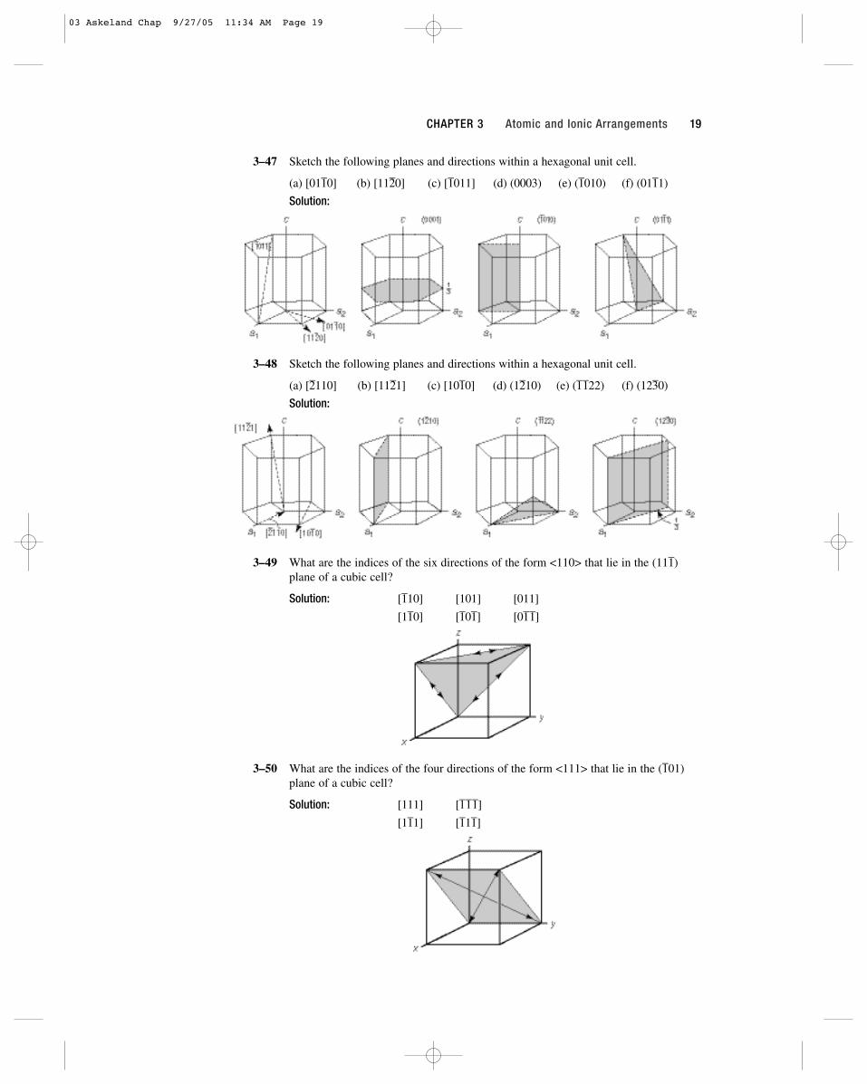
3–47 Sketch the following planes and directions within a hexagonal unit cell.
(a) [01–10] (b) [11–20] (c) [–1011] (d) (0003) (e) (–1010) (f) (01–11)
Solution:
3–48 Sketch the following planes and directions within a hexagonal unit cell.
(a) [–2110] (b) [11–21] (c) [10–10] (d) (1–210) (e) (–1–122) (f) (12–30)
Solution:
3–49 What are the indices of the six directions of the form <110> that lie in the (11–1)plane of a cubic cell?
Solution: [–110] [101] [011]
[1–10] [–10–1] [0–1–1]
3–50 What are the indices of the four directions of the form <111> that lie in the (1–01)plane of a cubic cell?
Solution: [111] [–1–1–1]
[1–11] [–11–1]
CHAPTER 3 Atomic and Ionic Arrangements 19
03 Askeland Chap 9/27/05 11:34 AM Page 19

3–51 Determine the number of directions of the form <110> in a tetragonal unit cell andcompare to the number of directions of the form <110> in an orthorhombic unit cell.
Solution: Tetragonal: [110], [–1–10], [–110], [1–10] = 4
Orthorhombic: [110], [–1–10] = 2
Note that in cubic systems, there are 12 directions of the form <110>.
3–52 Determine the angle between the [110] direction and the (110) plane in a tetragonalunit cell; then determine the angle between the [011] direction and the (011) planein a tetragonal cell. The lattice parameters are a0 = 4 Å and c0 = 5 Å. What isresponsible for the difference?
Solution: [110] ⊥ (110)
tan(u/2) = 2.5 / 2 = 1.25
u/2 = 51.34o
u = 102.68o
The lattice parameters in the x and y directions are the same; thisallows the angle between [110] and (110) to be 90o. But the latticeparameters in the y and z directions are different!
3–53 Determine the Miller indices of the plane that passes through three points having thefollowing coordinates.
(a) 0,0,1; 1,0,0; and 1⁄2,1⁄2,0
(b) 1⁄2,0,1; 1⁄2,0,0; and 0,1,0
(c) 1,0,0; 0,1,1⁄2; and 1,1⁄2,1⁄4
(d) 1,0,0; 0,0,1⁄4; and 1⁄2,1,0
Solution:
(a) (111) (b) (210) (c) (0–12) (d) (218)
4
4
5
θθ2
2.5
4
5θ2
20 The Science and Engineering of Materials Instructor’s Solutions Manual
03 Askeland Chap 9/27/05 11:34 AM Page 20

3–54 Determine the repeat distance, linear density, and packing fraction for FCC nickel,which has a lattice parameter of 0.35167 nm, in the [100], [110], and [111] direc-tions. Which of these directions is close packed?
Solution:
For [100]: repeat distance = ao = 0.35167 nm
linear density = 1/ao = 2.84 points/nm
linear packing fraction = (2)(0.1243)(2.84) = 0.707
For [110]: repeat distance = ao/2 = 0.2487 nm
linear density = ao = 4.02 points/nm
linear packing fraction = (2)(0.1243)(4.02) = 1.0
For [111]: repeat distance = ao = 0.6091 nm
linear density = 1/ ao = 1.642 points/nm
linear packing fraction = (2)(0.1243)(1.642) = 0.408
Only the [110] is close packed; it has a linear packing fraction of 1.
3–55 Determine the repeat distance, linear density, and packing fraction for BCC lithium,which has a lattice parameter of 0.35089 nm, in the [100], [110], and [111] direc-tions. Which of these directions is close packed?
Solution:
For [100]: repeat distance = ao = 0.35089 nm
linear density = 1/ao = 2.85 points/nm
linear packing fraction = (2)(0.1519)(2.85) = 0.866
For [110]: repeat distance = ao = 0.496 nm
linear density = 1/ ao = 2.015 points/nm
linear packing fraction = (2)(0.1519)(2.015) = 0.612
2
2
r = 3(0.35089) / 4 = 0.1519 nm
3
3
2 / 2
2
r = 2( )(0.35167) / 4 = 0.1243 nm
CHAPTER 3 Atomic and Ionic Arrangements 21
03 Askeland Chap 9/27/05 11:34 AM Page 21
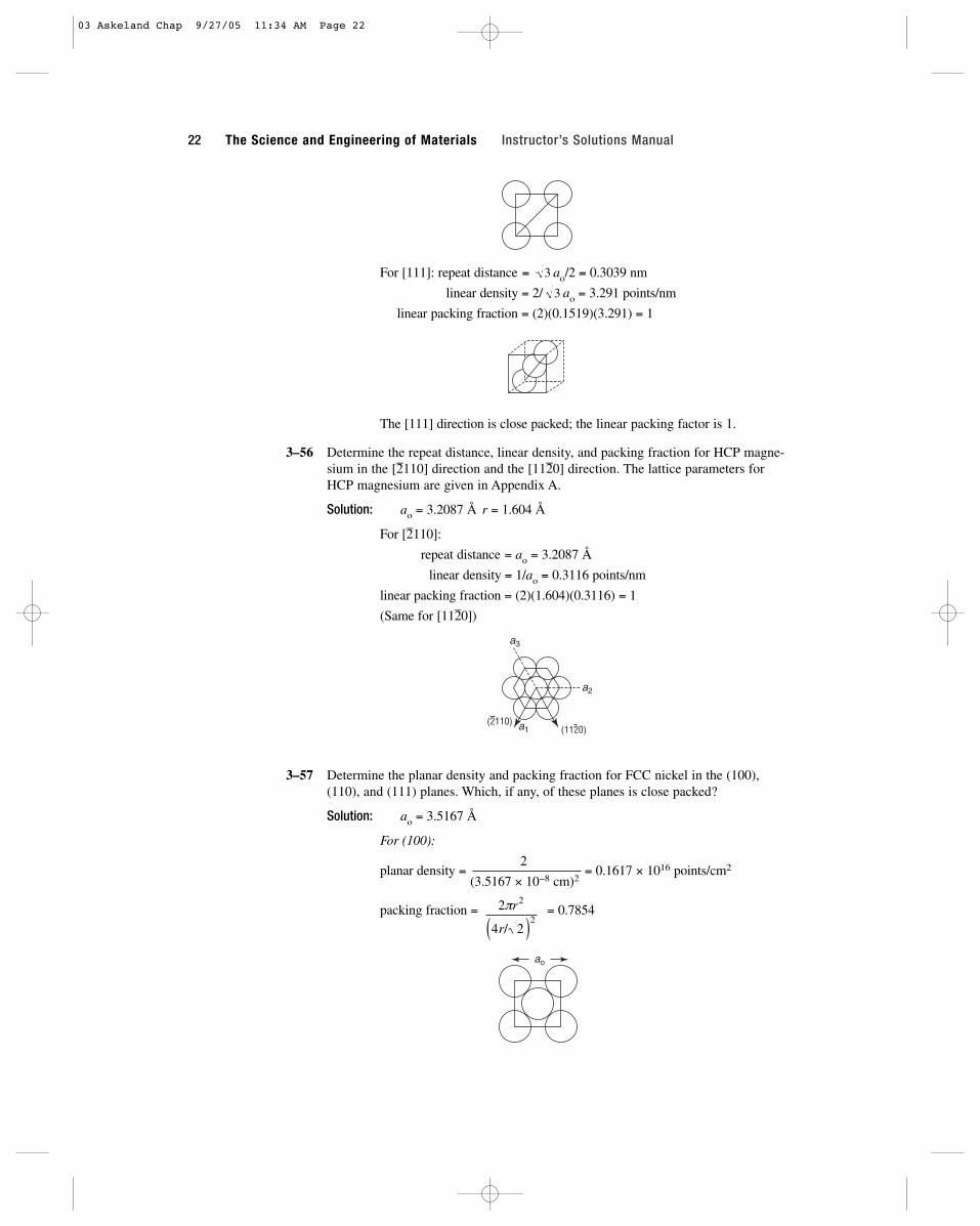
For [111]: repeat distance = ao/2 = 0.3039 nm
linear density = 2/ ao = 3.291 points/nm
linear packing fraction = (2)(0.1519)(3.291) = 1
The [111] direction is close packed; the linear packing factor is 1.
3–56 Determine the repeat distance, linear density, and packing fraction for HCP magne-sium in the [–2110] direction and the [11–20] direction. The lattice parameters forHCP magnesium are given in Appendix A.
Solution: ao = 3.2087 Å r = 1.604 Å
For [–2110]:
repeat distance = ao = 3.2087 Å
linear density = 1/ao = 0.3116 points/nm
linear packing fraction = (2)(1.604)(0.3116) = 1
(Same for [112–0])
3–57 Determine the planar density and packing fraction for FCC nickel in the (100),(110), and (111) planes. Which, if any, of these planes is close packed?
Solution: ao = 3.5167 Å
For (100):
planar density =2
= 0.1617 × 10¹⁶ points/cm2
(3.5167 × 10⁻⁸ cm)2
packing fraction = = 0.7854
ao
2
4 2
2
2πr
r/( )
(1120)(2110) a1
a2
a3
3
3
22 The Science and Engineering of Materials Instructor’s Solutions Manual
03 Askeland Chap 9/27/05 11:34 AM Page 22

For (110):
planar density =2 points
(3.5167 × 10⁻⁸ cm) (3.5167 × 10⁻⁸ cm)
= 0.1144 × 10⁻¹⁶ points/cm2
packing fraction = = 0.555
For (111):From the sketch, we can determine that the area of the (111) plane is
. There are (3)(1⁄2) + (3)(1⁄6) = 2 atoms in this area.
planar density =2 points
0.866(3.5167 × 10⁻⁸ cm)2
= 0.1867 × 10¹⁶ points/cm2
packing fraction = = 0.907
The (111) is close packed.
3–58 Determine the planar density and packing fraction for BCC lithium in the (100),(110), and (111) planes. Which, if any, of these planes is close packed?
Solution: ao = 3.5089 Å
For (100):
planar density =1
= 0.0812 × 10¹⁶ points/cm2
(3.5089 × 10⁻⁸ cm)2
packing fraction = = 0.589π 3ao /4[ ]
2
ao2
2p 2ao/4( )2
0.866ao2
2ao/2( ) 3ao/ 2( ) = 0.866ao2
2ao
ao
2pr2
2 4r/ 2( )2
2( )
CHAPTER 3 Atomic and Ionic Arrangements 23
03 Askeland Chap 9/27/05 11:34 AM Page 23

For (110):
planar density = = 0.1149 × 10¹⁶ points/cm2
packing fraction = = 0.833
For (111):
There are only (3)(1⁄6) = 1⁄2 points in the plane, which has an area of 0.866ao2.
planar density =1⁄2
= 0.0469 × 10¹⁶ points/cm2
0.866(3.5089 × 10⁻⁸ cm)2
packing fraction = = 0.34
There is no close-packed plane in BCC structures.
3–59 Suppose that FCC rhodium is produced as a 1-mm thick sheet, with the (111) planeparallel to the surface of the sheet. How many (111) interplanar spacings d111 thickis the sheet? See Appendix A for necessary data.
Solution:
thickness =(1 mm/10 mm/cm)
= 4.563 × 10⁶ d111 spacings2.1916 × 10−8 cm
3–60 In a FCC unit cell, how many d111 are present between the 0,0,0 point and the 1,1,1point?
Solution: The distance between the 0,0,0 and 1,1,1 points is ao. The interplanarspacing is
Therefore the number of interplanar spacings is
number of d111 spacings = ao/(ao/ ) = 333
d a a1112 2 21 1 1 3= + + =o o/ /
3
da
111 2 21 1
3 7962 1916=
+ += =o
21
Å
3 Å
..
A = 0.866 a2
12
2
2
3 4
0 866
π a
a
o
o
/
.
[ ]1⁄2
ao
2ao
2 3 4
2
2
2
π a
a
o
o
/[ ]
2
2 3 5089 10 82
. ×( )− cm
24 The Science and Engineering of Materials Instructor’s Solutions Manual
03 Askeland Chap 9/27/05 11:34 AM Page 24

3–62 Determine the minimum radius of an atom that will just fit into (a) the tetrahedralinterstitial site in FCC nickel and (b) the octahedral interstitial site in BCC lithium.
Solution: (a) For the tetrahedral site in FCC nickel (ao = 3.5167 Å):
r/rNi = 0.225 for a tetrahedral site. Therefore:
r = (1.243 Å)(0.225) = 0.2797 Å
(b) For the octahedral site in BCC lithium (ao = 3.5089 Å):
r/rLi = 0.414 for an octrahedral site. Therefore:
r = (1.519 Å)(0.414) = 0.629 Å
3–64 What is the radius of an atom that will just fit into the octahedral site in FCC copperwithout disturbing the crystal structure?
Solution: rCu = 1.278 Å
r/rCu = 0.414 for an octahedral site. Therefore:
r = (1.278 Å)(0.414) = 0.529 Å
3–65 Using the ionic radii given in Appendix B, determine the coordination numberexpected for the following compounds.
(a) Y2O3 (b) UO2 (c) BaO (d) Si3N4
(e) GeO2 (f) MnO (g) MgS (h) KBr
Solution:
(a) rY+3/rO
−2 =0.89
= 0.67 CN = 6 (e) rGe+4/rO
−2 =0.53
= 0.40 CN = 41.32 1.32
(b) rU+4/rO
−2 =0.97
= 0.73 CN = 6 (f) rMn+2/rO
−2 =0.80
= 0.61 CN = 61.32 1.32
(c) rO−2/rBa
+2 =1.32
= 0.99 CN = 8 (g) rMg+2/rS
−2 =0.66
= 0.50 CN = 61.34 1.32
(d) rN−3/rSi
+4 =0.15
= 0.36 CN = 4 (h) rK+1/rBy
−1 =1.33
= 0.68 CN = 60.42 1.96
rLi =3 3.5089( )
4= 1.519 Å
rNi =2 3.5167 Å( )
4= 1.243 Å
CHAPTER 3 Atomic and Ionic Arrangements 25
03 Askeland Chap 9/27/05 11:34 AM Page 25
3–66 Would you expect NiO to have the cesium chloride, sodium chloride, or zinc blendestructure? Based on your answer, determine (a) the lattice parameter, (b) the density,and (c) the packing factor.
Solution: rNi+2 = 0.69 Å rO
−2 = 1.32 ÅrNi
+2
= 0.52 CN = 6rO
−2
A coordination number of 8 is expected for the CsCl structure, and acoordination number of 4 is expected for ZnS. But a coordination num-ber of 6 is consistent with the NaCl structure.
(a) ao = 2(0.69) + 2(1.32) = 4.02 Å
(b) r =(4 of each ion/cell)(58.71 + 16 g/mol)
= 7.64 g/cm3
(4.02 × 10⁻⁸ cm)3(6.02 × 10²³ atoms/mol)
(c) PF =(4π/3)(4 ions/cell)[(0.69)3 + (1.32)3]
= 0.678(4.02)3
3–67 Would you expect UO2 to have the sodium chloride, zinc blende, or fluorite struc-ture? Based on your answer, determine (a) the lattice parameter, (b) the density, and(c) the packing factor.
Solution: rU+4 = 0.97 Å rO
−2 = 1.32 ÅrU
+4
= 0.97/1.32 = 0.735rO
−2
valence of U = +4, valence of O = −2
The radius ratio predicts a coordination number of 8; however there mustbe twice as many oxygen ions as uranium ions in order to balance thecharge. The fluorite structure will satisfy these requirements, with:
U = FCC position (4) O = tetrahedral position (8)
(a) ao = 4ru + 4ro = 4(0.97 + 1.32) = 9.16 or ao = 5.2885 Å
(b) r =4(238.03 g/mol) + 8(16 g/mol)
= 12.13 g/cm3
(5.2885 × 10⁻⁸ cm)3 (6.02 × 10²³ atoms/mol)
(c) PF =(4π/3)[4(0.97)3 + 8(1.32)3]
= 0.624(5.2885)3
3–68 Would you expect BeO to have the sodium chloride, zinc blende, or fluorite struc-ture? Based on your answer, determine (a) the lattice parameter, (b) the density, and(c) the packing factor.
Solution: rBe+2 = 0.35 Å rO
−2 = 1.32 Å
rBe/rO = 0.265 CN = 4 ∴ Zinc Blende
(a) ao = 4rBe+2 + 4rO
−2 = 4(0.35 + 1.32) = 6.68 or ao = 3.8567 Å
(b) r =4(9.01 + 16 g/mol)
= 2.897 g/cm3
(3.8567 × 10⁻⁸ cm)3 (6.02 × 10²³ atoms/mol)
(c) PF =(4π/3)(4)[(0.35)3 + 8(1.32)3]
= 0.684(3.8567)3
3
3
26 The Science and Engineering of Materials Instructor’s Solutions Manual
03 Askeland Chap 9/27/05 11:34 AM Page 26
3–69 Would you expect CsBr to have the sodium chloride, zinc blende, fluorite, or cesiumchloride structure? Based on your answer, determine (a) the lattice parameter,(b) the density, and (c) the packing factor.
Solution: rCs+1 = 1.67 Å rBr
−1 = 1.96 Å
rCs+1
= 0.852 CN = 8 ∴ CsClrBr
−1
(a) ao = 2rCs+1 + 2rBr
−1 = 2(1.96 + 1.67) = 7.26 or ao = 4.1916 Å
(b) r =79.909 + 132.905 g/mol
= 4.8 g/cm3
(4.1916 × 10⁻⁸ cm)3 (6.02 × 10²³ atoms/mol)
(c) PF =(4π/3)[(1.96)3 + (1.67)3]
= 0.693(4.1916)3
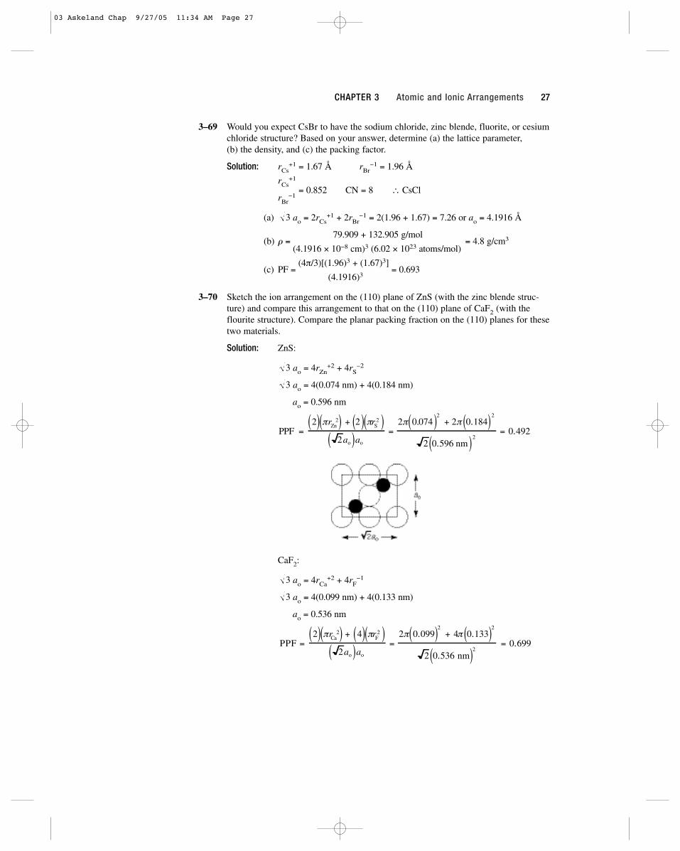
3–70 Sketch the ion arrangement on the (110) plane of ZnS (with the zinc blende struc-ture) and compare this arrangement to that on the (110) plane of CaF2 (with theflourite structure). Compare the planar packing fraction on the (110) planes for thesetwo materials.
Solution: ZnS:
ao = 4rZn+2 + 4rS
−2
ao = 4(0.074 nm) + 4(0.184 nm)
ao = 0.596 nm
CaF2:
ao = 4rCa+2 + 4rF
−1
ao = 4(0.099 nm) + 4(0.133 nm)
ao = 0.536 nm
PPF =2( ) πrCa
2( ) + 4( ) πrF2( )
2ao( )ao
=2π 0.099( )2
+ 4π 0.133( )2
2 0.536 nm( )2= 0.699
3
3
PPF =2( ) πrZn
2( ) + 2( ) πrS2( )
2ao( )ao
=2π 0.074( )2
+ 2π 0.184( )2
2 0.596 nm( )2= 0.492
3
3
3
CHAPTER 3 Atomic and Ionic Arrangements 27
03 Askeland Chap 9/27/05 11:34 AM Page 27

3–71 MgO, which has the sodium chloride structure, has a lattice parameter of 0.396 nm.Determine the planar density and the planar packing fraction for the (111) and (222)planes of MgO. What ions are present on each plane?
Solution: As described in the answer to Problem 3–57, the area of the (111) planeis 0.866ao
2.
ao = 2rMg+2 + 2rO
−2 = 2(0.66 + 1.32) = 3.96 Å
(111): P.D. =2 Mg
= 0.1473 × 10¹⁶ points/cm2
(0.866)(3.96 × 10⁻⁸ cm)2
(111): PPF =2π(0.66)2
= 0.202(0.866)(3.96)2
(222): P.D. = 0.1473 × 10¹⁶ points/cm2
(111): PPF =2π(1.32)2
= 0.806(0.866)(3.96)2
3–75 A diffracted x-ray beam is observed from the (220) planes of iron at a 2u angle of99.1o when x-rays of 0.15418 nm wavelength are used. Calculate the lattice parame-ter of the iron.
Solution: sin u = l/2d220
sin(99.1/2) =
3–76 A diffracted x-ray beam is observed from the (311) planes of aluminum at a 2uangle of 78.3o when x-rays of 0.15418 nm wavelength are used. Calculate the latticeparameter of the aluminum.
Solution: sin u = l /d311
aosin
nm=+ +
( )=
0 15418 3 1 1
2 78 3 20 40497
2 2 2.
. /.
aosin
nm=( )
=0 15418 8
2 49 550 2865
.
..
0 15418 2 2 0
2
2 2 2. + +
ao
(111)
(222)
ao
2ao
28 The Science and Engineering of Materials Instructor’s Solutions Manual
03 Askeland Chap 9/27/05 11:34 AM Page 28
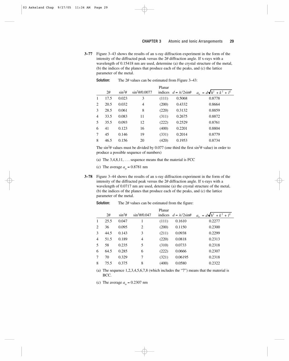
3–77 Figure 3–43 shows the results of an x-ray diffraction experiment in the form of theintensity of the diffracted peak versus the 2u diffraction angle. If x-rays with awavelength of 0.15418 nm are used, determine (a) the crystal structure of the metal,(b) the indices of the planes that produce each of the peaks, and (c) the latticeparameter of the metal.
Solution: The 2u values can be estimated from Figure 3–43:
Planar2u sin2u sin2u/0.0077 indices d = l /2sinu
1 17.5 0.023 3 (111) 0.5068 0.8778
2 20.5 0.032 4 (200) 0.4332 0.8664
3 28.5 0.061 8 (220) 0.3132 0.8859
4 33.5 0.083 11 (311) 0.2675 0.8872
5 35.5 0.093 12 (222) 0.2529 0.8761
6 41.5 0.123 16 (400) 0.2201 0.8804
7 45.5 0.146 19 (331) 0.2014 0.8779
8 46.5 0.156 20 (420) 0.1953 0.8734
The sin2u values must be divided by 0.077 (one third the first sin2u value) in order toproduce a possible sequence of numbers)
(a) The 3,4,8,11, . . . sequence means that the material is FCC
(c) The average ao = 0.8781 nm
3–78 Figure 3–44 shows the results of an x-ray diffraction experiment in the form of theintensity of the diffracted peak versus the 2u diffraction angle. If x-rays with awavelength of 0.0717 nm are used, determine (a) the crystal structure of the metal,(b) the indices of the planes that produce each of the peaks, and (c) the latticeparameter of the metal.
Solution: The 2u values can be estimated from the figure:
Planar2u sin2u sin2u/0.047 indices d = l /2sinu
1 25.5 0.047 1 (111) 0.16100 0.2277
2 36.5 0.095 2 (200) 0.11500 0.2300
3 44.5 0.143 3 (211) 0.09380 0.2299
4 51.5 0.189 4 (220) 0.08180 0.2313
5 58.5 0.235 5 (310) 0.07330 0.2318
6 64.5 0.285 6 (222) 0.06660 0.2307
7 70.5 0.329 7 (321) 0.06195 0.2318
8 75.5 0.375 8 (400) 0.05800 0.2322
(a) The sequence 1,2,3,4,5,6,7,8 (which includes the “7”) means that the material isBCC.
(c) The average ao = 0.2307 nm
ao = d h2 + k 2 + l2
ao = d h2 + k 2 + l2
CHAPTER 3 Atomic and Ionic Arrangements 29
03 Askeland Chap 9/27/05 11:34 AM Page 29

03 Askeland Chap 9/27/05 11:34 AM Page 30
31
4Imperfections in the Atomic and Ionic Arrangements
4–1 Calculate the number of vacancies per cm3 expected in copper at 1080oC (just belowthe melting temperature). The activation energy for vacancy formation is 20,000cal/mol.
Solution:n =
(4 atoms/u.c.) = 8.47 × 10²² atoms/cm3
(3.6151 × 10⁻⁸ cm)3
nv = 8.47 × 10²² exp[−20,000/(1.987)(1353)]
= 8.47 × 10²² exp(−7.4393) = 4.97 × 10¹⁹ vacancies/cm3
4-2 The fraction of lattice points occupied by vacancies in solid aluminum at 660oC is10−3. What is the activation energy required to create vacancies in aluminum?
Solution: nv/n = 10−3 = exp[−Q/(1.987)(933)]
ln(10−3) = −6.9078 = −Q/(1.987)(933)
Q = 12,800 cal/mol
4–3 The density of a sample of FCC palladium is 11.98 g/cm3 and its lattice parameter is3.8902 Å. Calculate (a) the fraction of the lattice points that contain vacancies and(b) the total number of vacancies in a cubic centimeter of Pd.
Solution:(a) 11.98 g/cm3 =
(x)(106.4 g/mol)
(3.8902 × 10⁻⁸ cm)3(6.02 × 10²³ atoms/mol)
x = 3.9905
fraction =4.0 − 3.9905
= 0.002375 4
04 Askeland Chap 9/27/05 11:35 AM Page 31

(b) number =0.0095 vacancies/u.c.
= 1.61 × 10²⁰ vacancies/cm3
(3.8902 × 10⁻⁸ cm)3
4–4 The density of a sample of HCP beryllium is 1.844 g/cm3 and the lattice parametersare a0 = 0.22858 nm and c0 = 0.35842 nm. Calculate (a) the fraction of the latticepoints that contain vacancies and (b) the total number of vacancies in a cubic cen-timeter.
Solution: Vu.c. = (0.22858 nm)2(0.35842 nm)cos30 = 0.01622 nm3
= 1.622 × 10⁻²³ cm3
(a) From the density equation:
1.844 g/cm3 =(x)(9.01 g/mol)
x = 1.9984(1.622 × 10⁻²³ cm3)(6.02 × 10²³ atoms/mol)
fraction =2 − 1.9984
= 0.00082
(b) number =0.0016 vacancies/uc
= 0.986 × 10²⁰ vacancies/cm3
1.622 × 10⁻²³ cm3
4–5 BCC lithium has a lattice parameter of 3.5089 × 10⁻⁸ cm and contains one vacancyper 200 unit cells. Calculate (a) the number of vacancies per cubic centimeter and(b) the density of Li.
Solution:(a)
1 vacancy = 1.157 × 10²⁰ vacancies/cm3
(200)(3.5089 × 10⁻⁸ cm)3
(b) In 200 unit cells, there are 399 Li atoms. The atoms/cell are 399/200:
r =(399/200)(6.94 g/mol)
= 0.532 g/cm3
(3.5089 × 10⁻⁸ cm)3(6.02 × 10²³ atoms/mol)
4–6 FCC lead has a lattice parameter of 0.4949 nm and contains one vacancy per 500 Pbatoms. Calculate (a) the density and (b) the number of vacancies per gram of Pb.
Solution: (a) The number of atoms/cell = (499/500)(4 sites/cell)
r =(499/500)(4)(207.19 g/mol)
= 11.335 g/cm3
(4.949 × 10⁻⁸ cm)3(6.02 × 10²³ atoms/mol)
(b) The 500 Pb atoms occupy 500 / 4 = 125 unit cells:
[(1/11.335 g/cm3)] = 5.82 × 10¹⁸ vacancies/g
4–7 A niobium alloy is produced by introducing tungsten substitutional atoms in theBCC structure; eventually an alloy is produced that has a lattice parameter of0.32554 nm and a density of 11.95 g/cm3. Calculate the fraction of the atoms in thealloy that are tungsten.
Solution:11.95 g/cm3 =
(xW)(183.85 g/mol) + (2 − xW)(92.91 g/mol)
(3.2554 × 10⁻⁸ cm)3(6.02 × 10²³ atoms/mol)
248.186 = 183.85xW + 185.82 − 92.91xW
90.94xW = 62.366 or xW = 0.69 W atoms/cell
1
3
vacancy
125 cells
(4.949 10 cm8×
⎛
⎝⎜
⎞
⎠⎟
×
− )
32 The Science and Engineering of Materials Instructor’s Solutions Manual
04 Askeland Chap 9/27/05 11:35 AM Page 32

There are 2 atoms per cell in BCC metals. Thus:
fw = 0.69/2 = 0.345
4–8 Tin atoms are introduced into a FCC copper crystal, producing an alloy with a lat-tice parameter of 3.7589 × 10⁻⁸ cm and a density of 8.772 g/cm3. Calculate theatomic percentage of tin present in the alloy.
Solution:8.772 g/cm3 =
(xSn)(118.69 g/mol) + (4 − xSn)(63.54 g/mol)
(3.7589 × 10⁻⁸ cm)3(6.02 × 10²³ atoms/mol)
280.5 = 55.15xSn + 254.16 or xSn = 0.478 Sn atoms/cell
There are 4 atoms per cell in FCC metals; therefore the at% Sn is:
(0.478/4) = 11.95%
4–9 We replace 7.5 atomic percent of the chromium atoms in its BCC crystal with tanta-lum. X-ray diffraction shows that the lattice parameter is 0.29158 nm. Calculate thedensity of the alloy.
Solution:r =
(2)(0.925)(51.996 g/mol) + 2(0.075)(180.95 g/mol)= 8.265 g/cm3
(2.9158 × 10⁻⁸ cm)3(6.02 × 10²³ atoms/mol)
4–10 Suppose we introduce one carbon atom for every 100 iron atoms in an interstitialposition in BCC iron, giving a lattice parameter of 0.2867 nm. For the Fe-C alloy,find (a) the density and (b) the packing factor.
Solution: There is one carbon atom per 100 iron atoms, or 1 C/50 unit cells, or 1/50 C per unit cell:
(a)r =
(2)(55.847 g/mol) + (1/50)(12 g/mol) = 7.89 g/cm3
(2.867 × 10⁻⁸ cm)3(6.02 × 10²³ atoms/mol)
(b)Packing Factor =
2(4π/3)(1.241)3 + (1/50)(4π/3)(0.77)3
= 0.681(2.867)3
4–11 The density of BCC iron is 7.882 g/cm3 and the lattice parameter is 0.2866 nmwhen hydrogen atoms are introduced at interstitial positions. Calculate (a) theatomic fraction of hydrogen atoms and (b) the number of unit cells required on aver-age that contain hydrogen atoms.
Solution:(a) 7.882 g/cm3 =
2(55.847 g/mol) + x(1.00797 g/mol)
(2.866 × 10⁻⁸ cm)3(6.02 × 10²³ atoms/mol)
x = 0.0081 H atoms/cell
The total atoms per cell include 2 Fe atoms and 0.0081 H atoms.Thus:
fH =0.0081
= 0.0042.0081
(b) Since there is 0.0081 H/cell, then the number of cells containing H atoms is:
cells = 1/0.0081 = 123.5 or 1 H in 123.5 cells
CHAPTER 4 Imperfections in the Atomic and Ionic Arrangements 33
04 Askeland Chap 9/27/05 11:35 AM Page 33

4–12 Suppose one Schottky defect is present in every tenth unit cell of MgO. MgO hasthe sodium chloride crystal structure and a lattice parameter of 0.396 nm. Calculate(a) the number of anion vacancies per cm3 and (b) the density of the ceramic.
Solution: In 10 unit cells, we expect 40 Mg + 40 O ions, but due to the defect:
40 Mg − 1 = 39
40 O − 1 = 39
(a) 1 vacancy/(10 cells)(3.96 × 10⁻⁸ cm)3 = 1.61 × 10²¹ vacancies/cm3
(b)r =
(39/40)(4)(24.312 g/mol) + (39/40)(4)(16 g/mol)= 4.205 g/cm3
(3.96 × 10⁻⁸ cm)3(6.02 × 10²³ atoms/mol)
4–13 ZnS has the zinc blende structure. If the density is 3.02 g/cm3 and the lattice param-eter is 0.59583 nm, determine the number of Schottky defects (a) per unit cell and(b) per cubic centimeter.
Solution: Let x be the number of each type of ion in the unit cell. There normally are 4 of each type.
(a) 3.02 g/cm3 =x(65.38 g/mol) + x(32.064 g/mol)
x = 3.9465(5.9583 × 10⁻⁸ cm)3(6.02 × 10²³ ions/mol)
4 − 3.9465 = 0.0535 defects/u.c.
(b) # of unit cells/cm3 = 1/(5.9683 × 10−8 cm)3 = 4.704 × 10²¹
Schottky defects per cm3 = (4.704 × 10²¹)(0.0535) = 2.517 × 10²⁰
4–14 Suppose we introduce the following point defects. What other changes in eachstructure might be necessary to maintain a charge balance? Explain.(a) Mg2+ ions substitute for yttrium atoms in Y2O3(b) Fe3+ ions substitute for magnesium ions in MgO(c) Li1+ ions substitute for magnesium ions in MgO(d) Fe2+ ions replace sodium ions in NaCl
Solution: (a) Remove 2 Y3+ and add 3 Mg2+ − create cation interstitial.
(b) Remove 3 Mg2+ and add 2 Fe3+ − create cation vacancy.
(c) Remove 1 Mg2+ and add 2 Li+ − create cation interstitial.
(d) Remove 2 Na+ and add 1 Fe2+ − create cation vacancy.
4–16 What are the Miller indices of the slip directions(a) on the (111) plane in an FCC unit cell(b) on the (011) plane in a BCC unit cell?
Solution: [01–1], [011–] [11–1], [1–11–][1–10], [11–0] [1–1–1], [111–][1–01], [101–]
x
y
z
x
y
z
34 The Science and Engineering of Materials Instructor’s Solutions Manual
04 Askeland Chap 9/27/05 11:35 AM Page 34

4–17 What are the Miller indices of the slip planes in FCC unit cells that include the[101] slip direction?
Solution: (111–), (1–1–1) (1–11), (11–1–)
4–18 What are the Miller indices of the {110} slip planes in BCC unit cells that includethe [111] slip direction?
Solution: (11–0), (1–10) (01–1), (011–) (101–), (1–01)
4–19 Calculate the length of the Burgers vector in the following materials:(a) BCC niobium (b) FCC silver (c) diamond cubic silicon
Solution: (a) The repeat distance, or Burgers vector, is half the body diagonal,or:
b = repeat distance = (1⁄2) (3.294 Å) = 2.853 Å
(b) The repeat distance, or Burgers vector, is half of the face diagonal,or:
b = (1⁄2) = (1⁄2) (4.0862 Å) = 2.889 Å
(c) The slip direction is [110], where the repeat distance is half of theface diagonal:
b = (1⁄2) (5.4307 Å) = 3.840 Å
4–20 Determine the interplanar spacing and the length of the Burgers vector for slip onthe expected slip systems in FCC aluminum. Repeat, assuming that the slip systemis a (110) plane and a [11–1] direction. What is the ratio between the shear stressesrequired for slip for the two systems? Assume that k = 2 in Equation 4-2.
Solution: (a) For (111)/[110],
b = (1⁄2) (4.04958 Å) = 2.863 Å
(b) If (110)/[111], then:
b = (4.04958 Å) = 7.014 Å d110 =4.04958 Å
12 +12 + 02= 2.863Å3
d111 =4.04958 Å
1+ 1+ 1= 2.338Å( 2 )
( 2 )
( 2 )( 2ao )
( 3 )
CHAPTER 4 Imperfections in the Atomic and Ionic Arrangements 35
04 Askeland Chap 9/27/05 11:35 AM Page 35
(c) If we assume that k = 2 in Equation 4-2, then
(d/b)a =2.338
= 0.8166 (d/b)b =2.863
= 0.4082.863 7.014
∴ta =
exp(−2(0.8166))= 0.44
tb exp(−2(0.408))
4–21 Determine the interplanar spacing and the length of the Burgers vector for slip onthe (110)/[11–1] slip system in BCC tantalum. Repeat, assuming that the slip systemis a (111)/[11–0] system. What is the ratio between the shear stresses required forslip for the two systems? Assume that k = 2 in Equation 4-2.
Solution: (a) For (110)/[11–1]:
b = (1⁄2) (3.3026 Å) = 2.860 Å
(b) If (111)/[11–0], then:
b = (3.3026 Å) = 4.671 Å
(c) If we assume that k = 2 in Equation 4-2, then:
(d/b)a =2.335
= 0.8166 (d/b)b =1.907
= 0.4082.86 4.671
ta =exp(−2(0.8166))
= 0.44tb exp(−2(0.408))
4–26 How many grams of aluminum, with a dislocation density of 1010 cm/cm3, arerequired to give a total dislocation length that would stretch from New York City toLos Angeles (3000 miles)?
Solution: (3000 mi)(5280 ft/mi)(12 in./ft)(2.54 cm/in.) = 4.828 × 108 cm
(4.828 × 108 cm)(2.699 g/cm3)= 0.13 g
(1010 cm/cm3)
4–27 The distance from Earth to the Moon is 240,000 miles. If this were the total lengthof dislocation in a cubic centimeter of material, what would be the dislocation density?
Solution: (240,000 mi)(5280 ft/mi)(12 in./ft)(2.54 cm/in.) = 3.86 × 1010 cm/cm3
4-30 Suppose you would like to introduce an interstitial or large substitutional atom intothe crystal near a dislocation. Would the atom fit more easily above or below thedislocation line shown in Figure 4-8(b)? Explain.
Solution: The atom would fit more easily into the area just below the dislocationdue to the atoms being pulled apart; this allows more space into whichthe atom can fit.
4–31 Compare the c/a ratios for the following HCP metals, determine the likely slipprocesses in each, and estimate the approximate critical resolved shear stress.Explain. (See data in Appendix A)(a) zinc (b) magnesium (c) titanium(d) zirconium (e) rhenium (f) beryllium
Solution: We expect metals with c/a > 1.633 to have a low tcrss:
d111 2 2 2
3
1 1 11 907=
+ +=
.3026 ÅÅ.2
d110 2 2 2
3
1 1 02 335=
+ +=
.3026 ÅÅ.( )3
36 The Science and Engineering of Materials Instructor’s Solutions Manual
04 Askeland Chap 9/27/05 11:35 AM Page 36
(a) Zn:4.9470
= 1.856 − low tcrss (b) Mg:5.209
= 1.62 − medium tcrss2.6648 3.2087
(c) Ti:4.6831
= 1.587 − high tcrss (d) Zr:5.1477
= 1.593 − high tcrss2.9503 3.2312
(e) Rh:4.458
= 1.615 − medium tcrss (f) Be:3.5842
= 1.568 − high tcrss2.760 2.2858
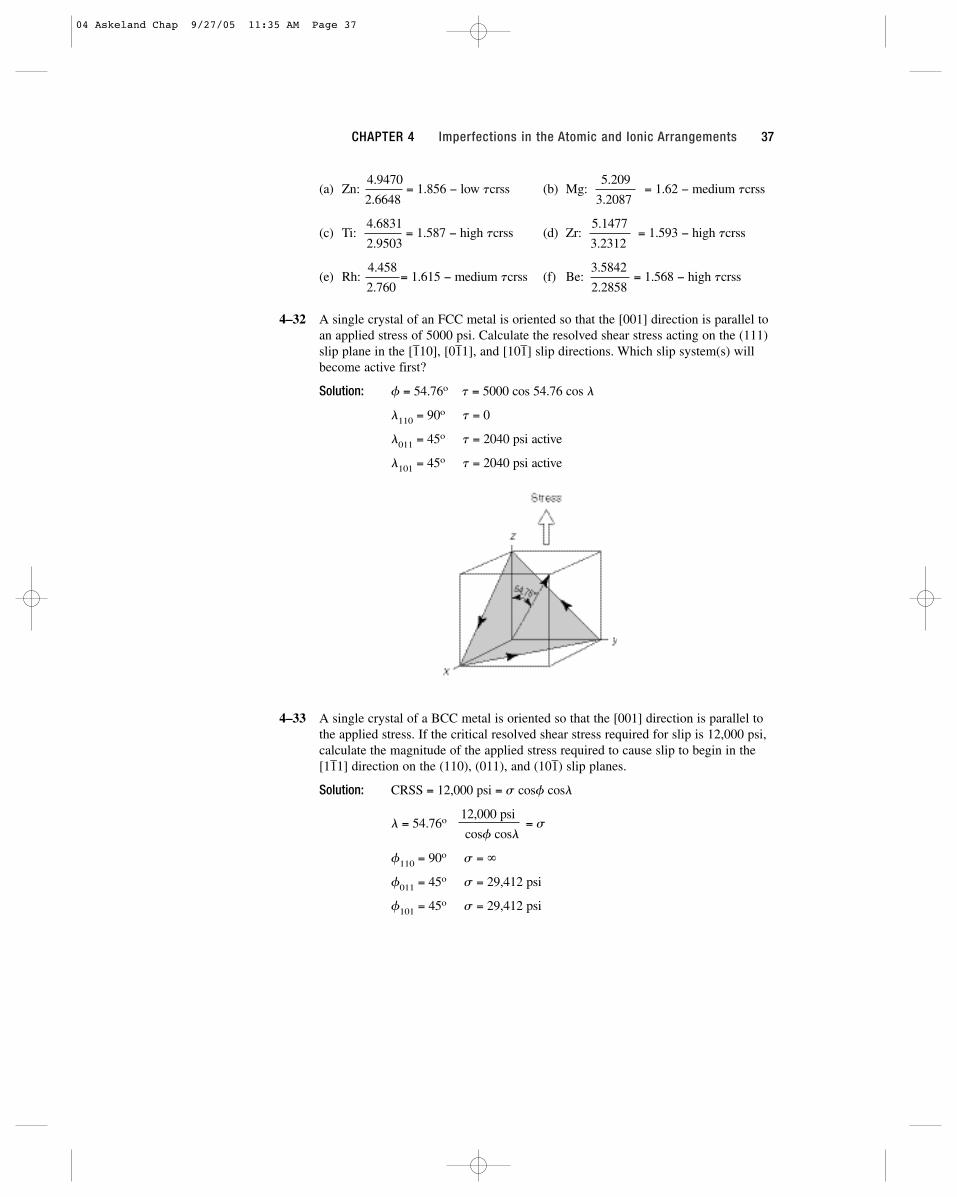
4–32 A single crystal of an FCC metal is oriented so that the [001] direction is parallel toan applied stress of 5000 psi. Calculate the resolved shear stress acting on the (111)slip plane in the [1–10], [01–1], and [101–] slip directions. Which slip system(s) willbecome active first?
Solution: f = 54.76o t = 5000 cos 54.76 cos l
l110 = 90o t = 0
l011 = 45o t = 2040 psi active
l101 = 45o t = 2040 psi active
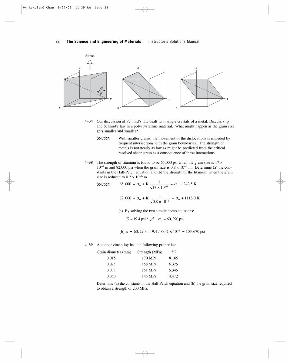
4–33 A single crystal of a BCC metal is oriented so that the [001] direction is parallel tothe applied stress. If the critical resolved shear stress required for slip is 12,000 psi,calculate the magnitude of the applied stress required to cause slip to begin in the[11–1] direction on the (110), (011), and (101–) slip planes.
Solution: CRSS = 12,000 psi = s cosf cosl
l = 54.76o 12,000 psi = s
cosf cosl
f110 = 90o s = ∞
f011 = 45o s = 29,412 psi
f101 = 45o s = 29,412 psi
CHAPTER 4 Imperfections in the Atomic and Ionic Arrangements 37
04 Askeland Chap 9/27/05 11:35 AM Page 37
4–34 Our discussion of Schmid’s law dealt with single crystals of a metal. Discuss slipand Schmid’s law in a polycrystalline material. What might happen as the grain sizegets smaller and smaller?
Solution: With smaller grains, the movement of the dislocations is impeded by frequent intersections with the grain boundaries. The strength of metals is not nearly as low as might be predicted from the critical resolved shear stress as a consequence of these interactions.
4–38 The strength of titanium is found to be 65,000 psi when the grain size is 17 × 10−6 m and 82,000 psi when the grain size is 0.8 × 10⁻⁶ m. Determine (a) the con-stants in the Hall-Petch equation and (b) the strength of the titanium when the grainsize is reduced to 0.2 × 10⁻⁶ m.
Solution:
(a) By solving the two simultaneous equations:
4–39 A copper-zinc alloy has the following properties:
Grain diameter (mm) Strength (MPa) d−1⁄2
0.015 170 MPa 8.165
0.025 158 MPa 6.325
0.035 151 MPa 5.345
0.050 145 MPa 4.472
Determine (a) the constants in the Hall-Petch equation and (b) the grain size requiredto obtain a strength of 200 MPa.
( ) , . / . ,b psiσ = + × =−60 290 19 4 0 2 10 103 6706
K psi psio= =19 4 60 290. / ,d σ
82 0001
0 8 101118 0
6,
..= +
×= +
−σ σo oK K
65 0001
17 10242 5
6, .= +
×= +
−σ σo oK K
x
y
z
54.7
6°
Stress
x
y
z
x
y
z
38 The Science and Engineering of Materials Instructor’s Solutions Manual
04 Askeland Chap 9/27/05 11:35 AM Page 38
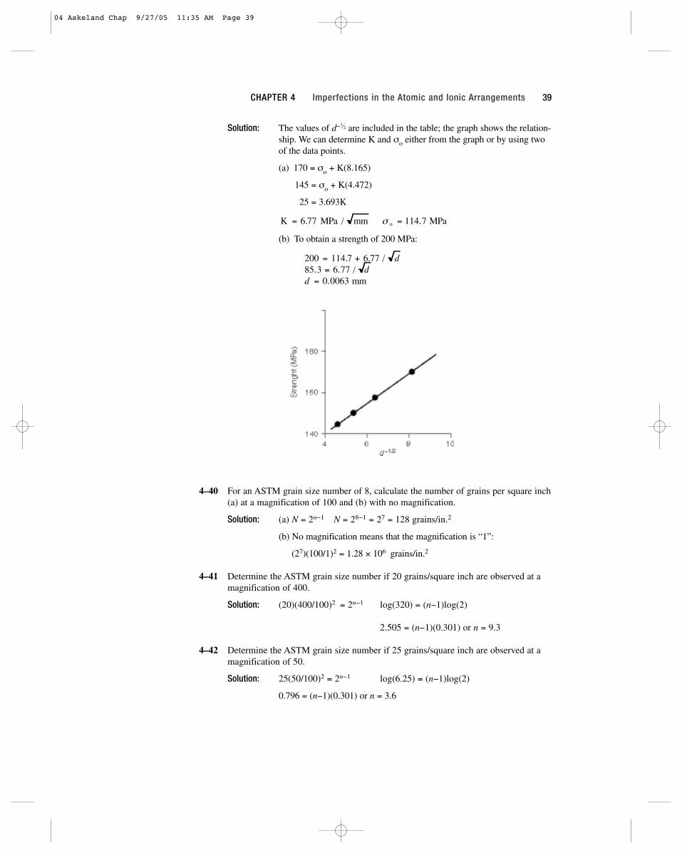
Solution: The values of d−1⁄2 are included in the table; the graph shows the relation-
ship. We can determine K and σo either from the graph or by using twoof the data points.
(a) 170 = σo + K(8.165)
145 = σo + K(4.472)
25 = 3.693K
(b) To obtain a strength of 200 MPa:
4–40 For an ASTM grain size number of 8, calculate the number of grains per square inch(a) at a magnification of 100 and (b) with no magnification.
Solution: (a) N = 2n−1 N = 28−1 = 27 = 128 grains/in.2
(b) No magnification means that the magnification is “1”:
(27)(100/1)2 = 1.28 × 10⁶ grains/in.2
4–41 Determine the ASTM grain size number if 20 grains/square inch are observed at amagnification of 400.
Solution: (20)(400/100)2 = 2n−1 log(320) = (n−1)log(2)
2.505 = (n−1)(0.301) or n = 9.3
4–42 Determine the ASTM grain size number if 25 grains/square inch are observed at amagnification of 50.
Solution: 25(50/100)2 = 2n−1 log(6.25) = (n−1)log(2)
0.796 = (n−1)(0.301) or n = 3.6
200 = 114.7 + 6.77 / d85.3 = 6.77 / dd = 0.0063 mm
K = 6.77 MPa / mm σ o = 114.7 MPa
CHAPTER 4 Imperfections in the Atomic and Ionic Arrangements 39
04 Askeland Chap 9/27/05 11:35 AM Page 39
4–43 Determine the ASTM grain size number for the materials in(a) Figure 4-17 (b) Figure 4-21
Solution: (a) There are about 26 grains in the photomicrograph, which has thedimensions 2.375 in. × 2 in. The magnification is 100, thus:
26 = 2n−1 log(5.47) = 0.738 = (n−1)log(2) n = 3.5
(2.375)(2)
(b) There are about 59 grains in the photomicrograph, which has the dimensions 2.25 in. × 2 in. The magnification is 500, thus:
59(500/100)2
= 2n−1 log(328) = 2.516 = (n−1)log(2) n = 9.4(2.25)(2)
There are about 28 grains in the photomicrograph, which has the dimensions 2 in. × 2.25 in. The magnification is 200, thus:
28(200/100)2
= 2n−1 log(24.889) = 1.396 = (n−1)log(2) n = 5.6(2.25)(2)
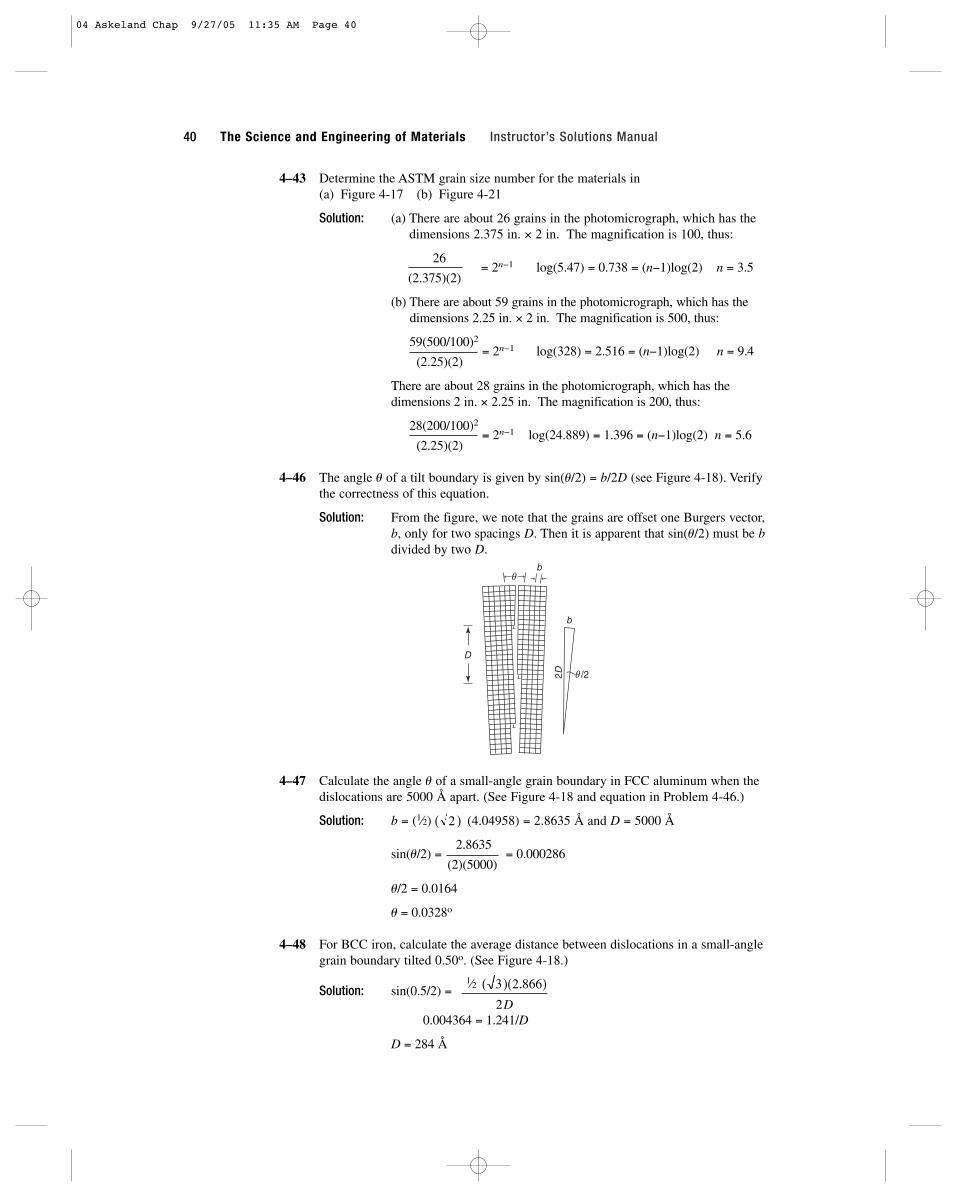
4–46 The angle u of a tilt boundary is given by sin(u/2) = b/2D (see Figure 4-18). Verifythe correctness of this equation.
Solution: From the figure, we note that the grains are offset one Burgers vector,b, only for two spacings D. Then it is apparent that sin(u/2) must be bdivided by two D.
4–47 Calculate the angle u of a small-angle grain boundary in FCC aluminum when thedislocations are 5000 Å apart. (See Figure 4-18 and equation in Problem 4-46.)
Solution: b = (1⁄2) (4.04958) = 2.8635 Å and D = 5000 Å
sin(u/2) =2.8635
= 0.000286(2)(5000)
u/2 = 0.0164
u = 0.0328o
4–48 For BCC iron, calculate the average distance between dislocations in a small-anglegrain boundary tilted 0.50o. (See Figure 4-18.)
Solution: sin(0.5/2) =
0.004364 = 1.241/D
D = 284 Å
( )( . )3 2 866
2D
( )2
D
b
b
2D /2
40 The Science and Engineering of Materials Instructor’s Solutions Manual
1⁄2
04 Askeland Chap 9/27/05 11:35 AM Page 40

41
5Atom and Ion Movements in Materials
5–8 Atoms are found to move from one lattice position to another at the rate of 5 × 10⁵
jumps/s at 400oC when the activation energy for their movement is 30,000 cal/mol.Calculate the jump rate at 750oC.
Solution:
Rate =5 × 105
=co exp[−30,000/(1.987)(673)]
= exp(−22.434 + 14.759)x co exp[−30,000/(1.987)(1023)]
5 × 105
= exp(−7.675) = 4.64 × 10⁻⁴
x
x =5 × 105
= 1.08 × 10⁹ jumps/s4.64 × 10-4
5–9 The number of vacancies in a material is related to temperature by an Arrheniusequation. If the fraction of lattice points containing vacancies is 8 × 10⁻⁵ at 600oC,determine the fraction at 1000oC.
Solution: 8 × 10−5 = exp[−Q/(1.987)(873)] Q = 16,364 cal/mol
f = nv/n = exp[−16,364/(1.987)(1273)] = 0.00155
5–15 The diffusion coefficient for Cr+3 in Cr2O3 is 6 × 10⁻¹⁵ cm2/s at 727oC and is 1 × 10⁻⁹ cm2/s at 1400oC. Calculate (a) the activation energy and (b) the constant D0.
Solution: (a) 6 × 10−15
=D0 exp[−Q/(1.987)(1000)]
1 × 10⁻⁹ D0 exp[−Q/(1.987)(1673)]
6 × 10−6 = exp[−Q(0.000503 − 0.00030)] = exp[−0.000203 Q]
−12.024 = −0.000203 Q or Q = 59,230 cal/mol
(b) 1 × 10−9 = D0 exp[−59,230/(1.987)(1673)] = D0 exp(−17.818)
1 × 10−9 = 1.828 × 10⁻⁸ D0 or D0 = 0.055 cm2/s
05 Askeland Chap 9/27/05 11:37 AM Page 41
5–16 The diffusion coefficient for O−2 in Cr2O3 is 4 × 10⁻¹⁵ cm2/s at 1150oC and 6 × 10⁻¹¹ cm2/s at 1715oC. Calculate (a) the activation energy and (b) the constantD0.
Solution:4 × 10−15
=D0 exp[−Q/(1.987)(1423)]
6 × 10⁻¹¹ D0 exp[−Q/(1.987)(1988)]
6.67 × 10−5 = exp[−0.0001005 Q]
−9.615 = −0.0001005 Q or Q = 95,700 cal/mol
4 × 10−15 = D0 exp[−95,700/(1.987)(1423)] = D0(2.02 × 10⁻¹⁵)
D0 = 1.98 cm2/s
5–23 A 0.2-mm thick wafer of silicon is treated so that a uniform concentration gradientof antimony is produced. One surface contains 1 Sb atom per 108 Si atoms and theother surface contains 500 Sb atoms per 108 Si atoms. The lattice parameter for Si is5.407 Å (Appendix A). Calculate the concentration gradient in (a) atomic percent Sbper cm and (b) Sb atoms/cm3 � cm.
Solution: ∆c/∆x =(1/108 − 500/108)
× 100% = −0.02495 at%/cm0.02 cm
a0 = 5.4307 Å Vunit cell = 160.16 × 10⁻²⁴ cm3
c1 =(8 Si atoms/u.c.)(1 Sb/108 Si)
= 0.04995 × 10¹⁶ Sb atoms/cm3
160.16 × 10⁻²⁴ cm3/u.c.
c2 =(8 Si atoms/u.c.)(500 Sb/108 Si)
= 24.975 × 10¹⁶ Sb atoms/cm3
160.16 × 10⁻²⁴ cm3/u.c.
∆c/∆x =(0.04995 − 24.975) × 1016
= −1.246 × 10¹⁹ Sb atoms/cm3 � cm0.02 cm
5–24 When a Cu-Zn alloy solidifies, one portion of the structure contains 25 atomic per-cent zinc and another portion 0.025 mm away contains 20 atomic percent zinc. Thelattice parameter for the FCC alloy is 3.63 × 10⁻⁸ cm. Determine the concentrationgradient in (a) atomic percent Zn per cm, (b) weight percent Zn per cm, and (c) Zn atoms/cm3.cm.
Solution: (a) ∆c/∆x =20% − 25%
= −2000 at% Zn/cm (0.025 mm)(0.1 cm/mm)
(b) We now need to determine the wt% of zinc in each portion:
wt% Zn =(20)(65.38 g/mol)
× 100 = 20.46(20)(65.38) + (80)(63.54)
wt% Zn =(25)(65.38 g/mol)
× 100 = 25.54(25)(65.38) + (75)(63.54)
∆c/∆x =20.46% − 25.54%
= −2032 wt% Zn/cm0.0025 cm
(c) Now find the number of atoms per cm3:
c1 =(4 atoms/cell)(0.2 Zn fraction)
= 0.0167 × 1024 Zn atoms/cm3
(3.63 × 10⁻⁸ cm)3
c2 =(4 atoms/cell)(0.25 Zn fraction)
= 0.0209 × 1024 Zn atoms/cm3
(3.63 × 10⁻⁸ cm)3
42 The Science and Engineering of Materials Instructor’s Solutions Manual
05 Askeland Chap 9/27/05 11:37 AM Page 42

∆c/∆x =0.0167 × 1024 − 0.0209 × 1024
= −1.68 Zn atoms/cm3 � cm 0.0025 cm
5–25 A 0.001-in. BCC iron foil is used to separate a high hydrogen gas from a low hydro-gen gas at 650oC. 5 × 10⁸ H atoms/cm3 are in equilibrium with the hot side of thefoil, while 2 × 10³ H atoms/cm3 are in equilibrium with the cold side Determine (a)the concentration gradient of hydrogen and (b) the flux of hydrogen through the foil.
Solution: (a) ∆c/∆x =2 × 10³ − 5 × 108
= −1969 × 108 H atoms/cm3 � cm(0.001 in.)(2.54 cm/in.)
(b) J = −D(∆c/∆x) = −0.0012 exp[−3600/(1.987)(923)](−1969 × 108)
J = 0.33 × 10⁸ H atoms/cm2 � s
5–26 A 1-mm sheet of FCC iron is used to contain nitrogen in a heat exchanger at1200oC. The concentration of N at one surface is 0.04 atomic percent and the con-centration at the second surface is 0.005 atomic percent. Determine the flux of nitro-gen through the foil in N atoms/cm2 � s.
Solution: (a) ∆c/∆x =(0.00005 − 0.0004)(4 atoms per cell)/(3.589 × 10−8 cm)3
(1 mm)(0.1 cm/mm)
= −3.03 × 10²⁰ N atoms/cm3 � cm
(b) J = −D(∆c/∆x) = −0.0034 exp[−34,600/(1.987)(1473)](−3.03 × 1020)
= 7.57 × 10¹² N atoms/cm2 � s
5–27 A 4-cm-diameter, 0.5-mm-thick spherical container made of BCC iron holds nitro-gen at 700oC. The concentration at the inner surface is 0.05 atomic percent and atthe outer surface is 0.002 atomic percent. Calculate the number of grams of nitrogenthat are lost from the container per hour.
Solution:∆c/∆x =
[0.00002 − 0.0005](2 atoms/cell)/(2.866 × 10−8 cm)3
(0.5 mm)(0.1 cm/mm)
= −8.16 × 10²⁰ N/cm3 � cm
J = −0.0047 exp[−18,300/(1.987)(973)][−8.16 × 1020] = 2.97 × 10¹⁴ N/cm2 � s
Asphere = 4πr2 = 4π(2 cm)2 = 50.27 cm2 t = 3600 s/h
N atoms/h = (2.97 × 10¹⁴)(50.27)(3600) = 5.37 × 10¹⁹ N atoms/h
N loss =(5.37 × 10¹⁹ atoms)(14.007 g/mol)
= 1.245 × 10⁻³ g/h(6.02 × 1023 atoms/mol)
5–28 A BCC iron structure is to be manufactured that will allow no more than 50 g ofhydrogen to be lost per year through each square centimeter of the iron at 400oC. Ifthe concentration of hydrogen at one surface is 0.05 H atom per unit cell and is0.001 H atom per unit cell at the second surface, determine the minimum thicknessof the iron.
Solution: c1 = 0.05 H/(2.866 × 10−8 cm)3 = 212.4 × 10¹⁹ H atoms/cm3
c2 = 0.001 H/(2.866 × 10−8 cm)3 = 4.25 × 10¹⁹ H atoms/cm3
∆c/∆x =4.25 × 10¹⁹ − 212.4 × 10¹⁹]
=−2.08 × 10²¹
∆x ∆x
CHAPTER 5 Atom and Ion Movements in Materials 43
05 Askeland Chap 9/27/05 11:37 AM Page 43

J =(50 g/cm2 y)(6.02 × 10²³ atoms/mol)
= 9.47 × 10¹⁷ H atoms/cm2 � s(1.00797 g/mol)(31.536 × 106 s/y)
J = 9.47 × 10¹⁷ H atoms/cm2 � s
= (−2.08 × 10²¹/∆x)(0.0012)exp[−3600/((1.987)(673))]
∆x = 0.179 cm
5–29 Determine the maximum allowable temperature that will produce a flux of less than2000 H atoms/cm2 � s through a BCC iron foil when the concentration gradient is −5 × 10¹⁶ atoms/cm3 � cm. (Note the negative sign for the flux.)
Solution:
2000 H atoms/cm2 � s = −0.0012 exp[−3600/1.987T][−5 × 1016 atoms/cm3 � cm]
ln(3.33 × 10⁻¹¹) = −3600/1.987T
T = −3600/((−24.12)(1.987)) = 75 K = −198oC
5–35 Compare the rate at which oxygen ions diffuse in Al2O3 with the rate at which alu-minum ions diffuse in Al2O3 at 1500oC. Explain the difference.
Solution: DO−2 = 1900 exp[−152,000/(1.987)(1773)] = 3.47 × 10⁻¹⁶ cm2/s
DAl+3 = 28 exp[−114,000/(1.987)(1773)] = 2.48 × 10⁻¹³ cm2/s
The ionic radius of the oxygen ion is 1.32 Å, compared with the aluminumionic radius of 0.51 Å; consequently it is much easier for the smalleraluminum ion to diffuse in the ceramic.
5–36 Compare the diffusion coefficients of carbon in BCC and FCC iron at the allotropictransformation temperature of 912oC and explain the difference.
Solution: DBCC = 0.011 exp[−20,900/(1.987)(1185)] = 1.51 × 10⁻⁶ cm2/s
DFCC = 0.23 exp[−32,900/(1.987)(1185)] = 1.92 × 10⁻⁷ cm2/s
Packing factor of the BCC lattice (0.68) is less than that of the FCC lattice; consequently atoms are expected to be able to diffuse more rapidly in the BCC iron.
5–37 Compare the diffusion coefficients for hydrogen and nitrogen in FCC iron at 1000oCand explain the difference in their values.
Solution: DH in BCC = 0.0063 exp[−10,300/(1.987)(1273)] = 1.074 × 10⁻⁴ cm2/s
DN in FCC = 0.0034 exp[−34,600/(1.987)(1273)] = 3.898 × 10⁻⁹ cm2/s
Nitrogen atoms have a larger atoms radius (0.71 Å) compared with that of hydrogen atoms (0.46 Å); the smaller hydrogen ions are expected to diffuse more rapidly.
5–41 A carburizing process is carried out on a 0.10% C steel by introducing 1.0% C atthe surface at 980oC, where the iron is FCC. Calculate the carbon content at 0.01cm, 0.05 cm, and 0.10 cm beneath the surface after 1 h.
Solution: D = 0.23 exp[−32,900/(1.987)(1253)] = 42 × 10−8 cm2/s
1
1 0 12 42 10 3600 0 07788−
−= × =−c
x xx
.[ / ( ( )( )] [ / . ]erf erf
44 The Science and Engineering of Materials Instructor’s Solutions Manual
05 Askeland Chap 9/27/05 11:37 AM Page 44

x = 0.01: erf[0.01/0.0778] = erf(0.1285) =(1 − cx) = 0.144 cx = 0.87% C
0.9
x = 0.05: erf[0.05/0.0778] = erf(0.643) =(1 − cx) = 0.636 cx = 0.43% C
0.9
x = 0.10: erf[0.10/0.0778] = erf(1.285) =(1 − cx) = 0.914 cx = 0.18% C
0.9
5–42 Iron containing 0.05% C is heated to 912oC in an atmosphere that produces 1.20% C at the surface and is held for 24 h. Calculate the carbon content at 0.05 cmbeneath the surface if (a) the iron is BCC and (b) the iron is FCC. Explain the dif-ference.
Solution: t = (24 h)(3600 s/h) = 86,400 s
DBCC = 0.011 exp[−20,900/(1.987)(1185)] = 1.54 × 10⁻⁶ cm2/s
DFCC = 0.23 exp[−32,900/(1.987)(1185)] = 1.97 × 10⁻⁷ cm2/s
BCC:1.2 − cx = erf[0.05/ = erf[0.0685] = 0.077
1.2 − 0.05
cx = 1.11% C
FCC:1.2 − cx = erf[0.05/ = erf[0.192] = 0.2139
1.2 − 0.05
cx = 0.95% C
Faster diffusion occurs in the looser packed BCC structure, leading tothe higher carbon content at point “x”.
5–43 What temperature is required to obtain 0.50% C at a distance of 0.5 mm beneath thesurface of a 0.20% C steel in 2 h, when 1.10% C is present at the surface? Assumethat the iron is FCC.
Solution:1.1 − 0.5
= 0.667 = erf[0.05/ ]1.1 − 0.2
0.05/ = 0.685 or = 0.0365 or Dt = 0.00133
t = (2 h)(3600 s/h) = 7200 s
D = 0.00133/7200 = 1.85 × 10−7 = 0.23 exp[−32,900/1.987T]
exp(−16,558/T) = 8.043 × 10⁻⁷
T = 1180K = 907oC
Dt2 Dt
2 Dt
( ( . )( , ) )]2 1 97 10 86 4007× −
( ( . )( , ) )]2 1 54 10 86 4006× −
1.0
0.5
% C
Surface 0.05 0.10 0.15x
CHAPTER 5 Atom and Ion Movements in Materials 45
05 Askeland Chap 9/27/05 11:37 AM Page 45

5–44 A 0.15% C steel is to be carburized at 1100o C, giving 0.35% C at a distance of1 mm beneath the surface. If the surface composition is maintained at 0.90% C,what time is required?
Solution:0.9 − 0.35
= 0.733 = erf[0.1/ ]0.9 − 0.15
0.1/ = 0.786 or = 0.0636 or Dt = 0.00405
D = 0.23 exp[−32,900/(1.987)(1373)] = 1.332 × 10⁻⁶ cm2/s
t = 0.00405/1.332 × 10−6 = 3040 s = 51 min
5–45 A 0.02% C steel is to be carburized at 1200oC in 4 h, with a point 0.6 mm beneaththe surface reaching 0.45% C. Calculate the carbon content required at the surfaceof the steel.
Solution:cs − 0.45
= erf[0.06/ ]cs − 0.02
D = 0.23 exp[−32,900/(1.987)(1473)] = 3.019 × 10⁻⁶ cm2/s
t = (4 h)(3600) = 14,400 s
erf[0.06/(2)(0.2085)] = erf(0.144) = 0.161
cs − 0.45= 0.161 or cs = 0.53% C
cs − 0.02
5–46 A 1.2% C tool steel held at 1150oC is exposed to oxygen for 48 h. The carbon con-tent at the steel surface is zero. To what depth will the steel be decarburized to lessthan 0.20% C?
Solution:0 − 0.2
= 0.1667 ∴ x/ = 0.1490 − 1.2
D = 0.23 exp[−32,900/(1.987)(1423)] = 2.034 × 10⁻⁶ cm2/s
t = (48 h)(3600 s/h) = 17.28 × 10⁴ s
= 0.5929
Then from above, x = (0.149)(2)(0.5929) = 0.177 cm
5–47 A 0.80% C steel must operate at 950oC in an oxidizing environment, where the car-bon content at the steel surface is zero. Only the outermost 0.02 cm of the steel partcan fall below 0.75% C. What is the maximum time that the steel part can operate?
Solution:0 − 0.75
= 0.9375 = erf[x/ ] ∴ x/ = 1.3840 − 0.8
0.02/ = 1.384 or = 0.007226 or Dt = 5.22 × 10⁻⁵
D = 0.23 exp[−32,900/(1.987)(1223)] = 3.03 × 10⁻⁷ cm2/s
t = 5.22 × 10⁻⁵ / 3.03 × 10−7 = 172 s = 2.9 min
5–48 A steel with BBC crystal structure containing 0.001% N is nitrided at 550oC for 5 h.If the nitrogen content at the steel surface is 0.08%, determine the nitrogen contentat 0.25 mm from the surface.
Dt2 Dt
2 Dt2 Dt
Dt
2 Dt
Dt = × =−( . )( , ) .3 019 10 14 400 0 20856
2 Dt
Dt2 Dt
2 Dt
46 The Science and Engineering of Materials Instructor’s Solutions Manual
05 Askeland Chap 9/27/05 11:37 AM Page 46

Solution:0.08 − cs = erf[0.025/ ] t = (5 h)(3600 s/h) = 1.8 × 10⁴ s
0.08 − 0.001
D = 0.0047 exp[−18,300/(1.987)(823)]
= 6.488 × 10⁻⁸ cm2/s
= 0.0342
erf[0.025/(2)(0.0342)] = erf(0.3655) = 0.394
0.08 − cs = 0.394 or cs = 0.049% N0.079
5–49 What time is required to nitride a 0.002 N steel to obtain 0.12% N at a distance of0.002 in. beneath the surface at 625oC? The nitrogen content at the surface is 0.15%.
Solution:0.15 − 0.12
= 0.2027 = erf[x/ ] ∴ x/ = 0.22560.15 − 0.002
D = 0.0047 exp[−18,300/(1.987)(898)] = 1.65 × 10⁻⁷ cm2/s
x = 0.002 in. = 0.00508 cm
Dt = 1.267 × 10⁻⁴ or t = 1.267 × 10⁻⁴/1.65 × 10−7 = 768 s = 12.8 min
5–50 We currently can successfully perform a carburizing heat treatment at 1200oC in 1 h. In an effort to reduce the cost of the brick lining in our furnace, we propose toreduce the carburizing temperature to 950oC. What time will be required to give us asimilar carburizing treatment?
Solution: D1200 = 0.23 exp[−32,900/(1.987)(1473)] = 3.019 × 10⁻⁶ cm2/s
D950 = 0.23 exp[−32,900/(1.987)(1223)] = 3.034 × 10⁻⁷ cm2/s
t1200 = 1 h
t950 = D1200 t1200/D950 =(3.019 × 10⁻⁶)(1)
= 9.95 h3.034 × 10−7
5–56 During freezing of a Cu-Zn alloy, we find that the composition is nonuniform. Byheating the alloy to 600oC for 3 hours, diffusion of zinc helps to make the composi-tion more uniform. What temperature would be required if we wished to performthis homogenization treatment in 30 minutes?
Solution: D600 = 0.78 exp[−43,900/(1.987)(873)] = 7.9636 × 10⁻¹² t600 = 3 h
tx = 0.5 h
Dx = D600 t600/tx = (7.9636 × 10⁻¹²)(3)/0.5
Dx = 4.778 × 10−11 = 0.78 exp[−43,900/1.987T]
ln (6.1258 × 10⁻¹¹) = −23.516 = −43,900/1.987 T
T = 940 K = 667oC
5–57 A ceramic part made of MgO is sintered successfully at 1700oC in 90 minutes. Tominimize thermal stresses during the process, we plan to reduce the temperature to
0 00508
2 1 65 100 2256
7
.
( . ).
×=
− t
2 Dt2 Dt
Dt
2 Dt
CHAPTER 5 Atom and Ion Movements in Materials 47
05 Askeland Chap 9/27/05 11:37 AM Page 47

1500oC. Which will limit the rate at which sintering can be done: diffusion of mag-nesium ions or diffusion of oxygen ions? What time will be required at the lowertemperature?
Solution: Diffusion of oxygen is the slower of the two, due to the larger ionic radius of the oxygen.
D1700 = 0.000043 exp[−82,100/(1.987)(1973)] = 3.455 × 10⁻¹⁴ cm2/s
D1500 = 0.000043 exp[−82,100/(1.987)(1773)] = 3.255 × 10⁻¹⁵ cm2/s
t1500 = D1700 t1700/D1500 =(3.455 × 10⁻¹⁴)(90)
= 955 min = 15.9 h3.255 × 10−15
5–58 A Cu-Zn alloy has an initial grain diameter of 0.01 mm. The alloy is then heated tovarious temperatures, permitting grain growth to occur. The times required for thegrains to grow to a diameter of 0.30 mm are
Temperature (oC) Time (min)
500 80,000
600 3,000
700 120
800 10
850 3
Determine the activation energy for grain growth. Does this correlate with the diffu-sion of zinc in copper? (Hint: Note that rate is the reciprocal of time.)
Solution: Temperature 1/T Time Rate(oC) (K) (K−1) (min) (min−1)
500 773 0.00129 80,000 1.25 × 10⁻⁵
600 873 0.00115 3,000 3.33 × 10⁻⁴
700 973 0.001028 120 8.33 × 10⁻³
800 1073 0.000932 10 0.100
850 1123 0.000890 3 0.333
From the graph, we find that Q = 51,286 cal/mol, which does correlatewith the activation energy for diffusion of zinc in copper.
10−1
10−2
10−3
10−4
10−5
0.0010 0.00121/T
Q/R = 25,810Q = 51,286
0.00123 – 0.0009
In (0
.25)
– In
(0.0
0005
)
Rat
e
48 The Science and Engineering of Materials Instructor’s Solutions Manual
05 Askeland Chap 9/27/05 11:37 AM Page 48
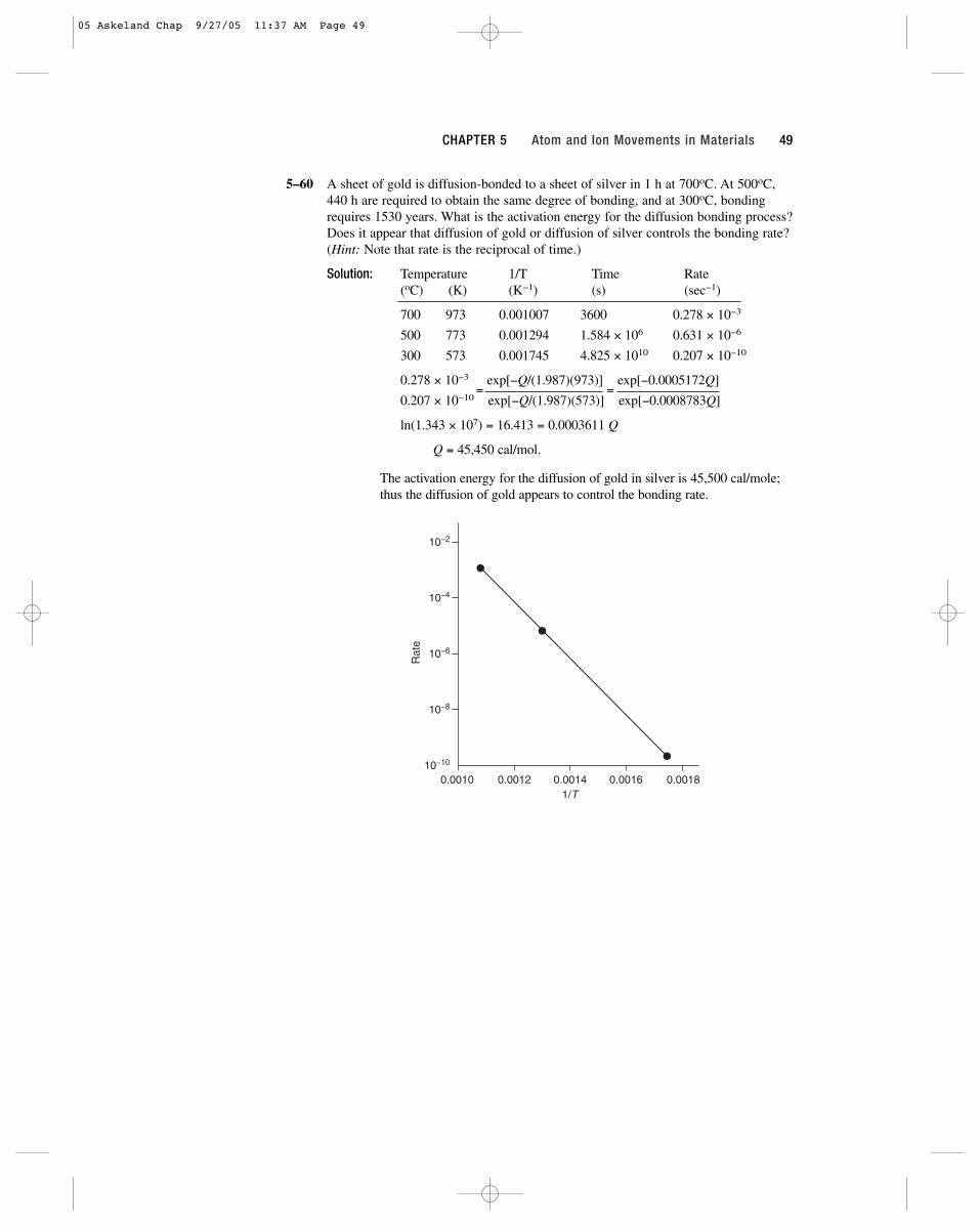
5–60 A sheet of gold is diffusion-bonded to a sheet of silver in 1 h at 700oC. At 500oC,440 h are required to obtain the same degree of bonding, and at 300oC, bondingrequires 1530 years. What is the activation energy for the diffusion bonding process?Does it appear that diffusion of gold or diffusion of silver controls the bonding rate?(Hint: Note that rate is the reciprocal of time.)
Solution: Temperature 1/T Time Rate(oC) (K) (K−1) (s) (sec−1)
700 973 0.001007 3600 0.278 × 10⁻³
500 773 0.001294 1.584 × 10⁶ 0.631 × 10⁻⁶
300 573 0.001745 4.825 × 10¹⁰ 0.207 × 10⁻¹⁰
0.278 × 10−3
=exp[−Q/(1.987)(973)]
=exp[−0.0005172Q]
0.207 × 10⁻¹⁰ exp[−Q/(1.987)(573)] exp[−0.0008783Q]
ln(1.343 × 10⁷) = 16.413 = 0.0003611 Q
Q = 45,450 cal/mol.
The activation energy for the diffusion of gold in silver is 45,500 cal/mole;thus the diffusion of gold appears to control the bonding rate.
10−2
10−4
10−6
10−8
10−10
0.0010 0.0012 0.0014 0.0016 0.00181/T
Rat
e
CHAPTER 5 Atom and Ion Movements in Materials 49
05 Askeland Chap 9/27/05 11:37 AM Page 49

05 Askeland Chap 9/27/05 11:37 AM Page 50
51
6Mechanical Properties and Behavior
6–24 A 850-lb force is applied to a 0.15-in.-diameter nickel wire having a yield strengthof 45,000 psi and a tensile strength of 55,000 psi. Determine (a) whether the wirewill plastically deform and (b) whether the wire will experience necking.
Solution: (a) First determine the stress acting on the wire:
s = F/A = 850 lb / (π/4)(0.15 in.)2 = 48,100 psi
Because s is greater than the yield strength of 45,000 psi, the wirewill plastically deform.
(b) Because s is less than the tensile strength of 55,000 psi, no neckingwill occur.
6–25 (a) A force of 100,000 N is applied to a 10 mm × 20 mm iron bar having a yieldstrength of 400 MPa and a tensile strength of 480 MPa. Determine whether thebar will plastically deform and whether the bar will experience necking.
Solution: First determine the stress acting on the wire:
s = F/A = 100,000 N / (10 mm)(20 mm) = 500 N/mm2 = 500 MPa
Because s is greater than the yield strength of 400 MPa, the wire willplastically deform.
Because s is greater than the tensile strength of 480 MPa, the wire willalso neck.
(b) Calculate the maximum force that a 0.2-in. diameter rod of Al2O3, having ayield strength of 35,000 psi, can withstand with no plastic deformation. Expressyour answer in pounds and Newtons.
Solution: F = σA = (35,000 psi)(π/4)(0.2 in.)2 = 1100 lb
F = (1100 lb)(4.448 N/lb) = 4891 N
06 Askeland Chap 9/27/05 11:39 AM Page 51

6–26 A force of 20,000 N will cause a 1 cm × 1 cm bar of magnesium to stretch from10 cm to 10.045 cm. Calculate the modulus of elasticity, both in GPa and psi.
Solution: The strain e is e = (10.045 cm − 10 cm)/10 cm = 0.0045 cm/cm
The stress s is s = 20,000 N / (10 mm)(10 mm) = 200 N/mm2
= 200 MPa
E = s/e = 200 MPa / 0.0045 cm/cm = 44,444 MPa = 44.4 GPa
E = (44,444 MPa)(145 psi/MPa) = 6.44 × 10⁶ psi
6–27 A polymer bar’s dimensions are 1 in. × 2 in. × 15 in. The polymer has a modulus ofelasticity of 600,000 psi. What force is required to stretch the bar elastically to 15.25 in.?
Solution: The strain e is e = (15.25 in. − 15 in.) / (15 in.) = 0.01667 in./in.
The stress s is s = Ee = (600,000 psi)(0.01667 in./in.) = 10,000 psi
The force is then F = sA = (10,000 psi)(1 in.)(2 in.) = 20,000 lb
6–28 An aluminum plate 0.5 cm thick is to withstand a force of 50,000 N with no perma-nent deformation. If the aluminum has a yield strength of 125 MPa, what is the min-imum width of the plate?
Solution: The area is A = F/s = 50,000 N / 125 N/mm2 = 400 mm2
The minimum width is w = A/t = (400 mm2)(0.1 cm/mm)2 / 0.5 cm = 8 cm
6–29 (a) A 3-in.-diameter rod of copper is to be reduced to a 2-in.-diameter rod by beingpushed through an opening. To account for the elastic strain, what should be thediameter of the opening? The modulus of elasticity for the copper is 17 × 106 psi and the yield strength is 40,000 psi.
Solution: (a) The strain is e = s/E = 40,000 psi / 17 × 106 psi = 0.00235 in./in.
The strain is also e = (2 in. − do) / do = 0.00235 in./in.
2 − do = 0.00235 do
do = 2 / 1.00235 = 1.995 in.
The opening in the die must be smaller than the final diameter.
6–30 A steel cable 1.25 in. in diameter and 50 ft long is to lift a 20-ton load. What is thelength of the cable during lifting? The modulus of elasticity of the steel is 30 × 106 psi.
Solution: The stress is s = F/A =(20 ton)(2000 lb/ton)
= 32,595 psi(π/4)(1.25 in.)2
The strain is e = s/E = 32,595 psi / 30 × 106 psi = 0.0010865 in./in.
e = (lf − 50 ft) / 50 ft = 0.0010865 ft/ft
lf = 50.0543 ft
6–33 The following data were collected from a standard 0.505-in.-diameter test specimenof a copper alloy (initial length (lo) = 2.0 in.):
52 The Science and Engineering of Materials Instructor’s Solutions Manual
06 Askeland Chap 9/27/05 11:39 AM Page 52

Load Gage Length Stress Strain(lb) (in.) (psi) (in./in.)
0 2.00000 0 0.0
3,000 2.00167 15,000 0.000835
6,000 2.00333 30,000 0.001665
7,500 2.00417 37,500 0.002085
9,000 2.0090 45,000 0.0045
10,500 2.040 52,500 0.02
12,000 2.26 60,000 0.13
12,400 2.50 (max load) 62,000 0.25
11,400 3.02 (fracture) 57,000 0.51
After fracture, the gage length is 3.014 in. and the diameter is 0.374 in. Plot the dataand calculate the 0.2% offset yield strength along with (a) the tensile strength, (b) themodulus of elasticity, (c) the % elongation, (d) the % reduction in area, (e) theengineering stress at fracture, (f) the true stress at fracture, and (g) the modulus ofresilience.
Solution: s = F / (π/4)(0.505)2 = F/0.2
e = (l − 2) / 2
0.2% offset yield strength = 45,000 psi
(a) tensile strength = 62,000 psi
(b) E = (30,000 − 0) / (0.001665 − 0) = 18 × 106 psi
(c) % elongation =(3.014 − 2)
× 100 = 50.7%2
(d) % reduction in area =(π/4)(0.505)2 − (π/4)(0.374)2
× 100 = 45.2%(π/4)(0.505)2
(e) engineering stress at fracture = 57,000 psi
(f) true stress at fracture = 11,400 lb / (π/4)(0.374)2 = 103,770 psi
(g) From the graph, yielding begins at about 37,500 psi. Thus:
1⁄2(yield strength)(strain at yield) = 1⁄2(37,500)(0.002085) = 39.1 psi
10
20
30
40
50
Str
ess
(ksi
)
yielding0.2% offset
0.002 0.01 0.02Strain (in./in.)
CHAPTER 6 Mechanical Properties and Behavior 53
06 Askeland Chap 9/27/05 11:39 AM Page 53

6–34 The following data were collected from a 0.4-in. diameter test specimen ofpolyvinyl chloride (lo = 2.0 in.):
Load Gage Length Stress Strain(lb) (in.) (psi) (in./in.)
0 2.00000 0 0.0
300 2.00746 2,387 0.00373
600 2.01496 4,773 0.00748
900 2.02374 7,160 0.01187
1200 2.032 9,547 0.016
1500 2.046 11,933 0.023
1660 2.070 (max load) 13,206 0.035
1600 2.094 12,729 0.047
1420 2.12 (fracture) 11,297 0.06
After fracture, the gage length is 2.09 in. and the diameter is 0.393 in. Plot the dataand calculate (a) the 0.2% offset yield strength, (b) the tensile strength, (c) themodulus of elasticity, (d) the % elongation, (e) the % reduction in area, (f) theengineering stress at fracture, (g) the true stress at fracture, and (h) the modulus ofresilience.
Solution: s = F /(π/4)(0.4)2 = F/0.1257
e = (l − 2) / 2
(a) 0.2% offset yield strength = 11,600 psi
(b) tensile strength = 12,729 psi
(c) E = (7160 − 0) / (0.01187 − 0) = 603,000 psi
(d) % elongation =(2.09 − 2)
× 100 = 4.5%2
(e) % reduction in area =(π/4)(0.4)2 − (π/4)(0.393)2
× 100 = 3.5%(π/4)(0.4)2
(f) engineering stress at fracture = 11,297 psi
(g) true stress at fracture = 1420 lb / (π/4)(0.393)2 = 11,706 psi
(h) From the figure, yielding begins near 9550 psi. Thus:
1⁄2(yield strength)(strain at yield) = 1⁄2(9550)(0.016) = 76.4 psi
2
4
6
8
10
12
14
Str
ess
(ksi
) Yielding
0.2% offset
0.002 0.01 0.02 0.03Strain (in./in.)
54 The Science and Engineering of Materials Instructor’s Solutions Manual
06 Askeland Chap 9/27/05 11:39 AM Page 54

6–35 The following data were collected from a 12-mm-diameter test specimen ofmagnesium (lo = 30.00 mm):
Load Gage Length Stress Strain(N) (mm) (MPa) (mm/mm)
0 30.0000 0 0.0
5,000 30.0296 44.2 0.000987
10,000 30.0592 88.4 0.001973
15,000 30.0888 132.6 0.00296
20,000 30.15 176.8 0.005
25,000 30.51 221.0 0.017
26,500 30.90 234.3 0.030
27,000 31.50 (max load) 238.7 0.050
26,500 32.10 234.3 0.070
25,000 32.79 (fracture) 221.0 0.093
After fracture, the gage length is 32.61 mm and the diameter is 11.74 mm. Plot thedata and calculate (a) the 0.2% offset yield strength, (b) the tensile strength, (c) themodulus of elasticity, (d) the % elongation, (e) the % reduction in area, (f) theengineering stress at fracture, (g) the true stress at fracture, and (h) the modulus ofresilience.
Solution: s = F / (π/4)(12 mm)2 = F/113.1
e = (l − 30)/30
(a) 0.2% offset yield strength = 186 MPa
(b) tensile strength = 238.7 MPa
(c) E = (132.6 − 0) / (0.00296 − 0) = 44,800 MPa = 44.8 GPa
(d) % elongation =(32.61 − 30)
× 100 = 8.7%30
(e) % reduction in area =(π/4)(12)2 − (π/4)(11.74)2
× 100 = 4.3%(π/4)(12)2
(f) engineering stress at fracture = 221 MPa
(g) true stress at fracture = 25,000 N / (π/4)(11.74)2 = 231 MPa
50
100
150
200
250
Str
ess
(Mpa
)
0.2% offset
0.001 0.01 0.030.02Strain (mm/mm)
Yie
lding
CHAPTER 6 Mechanical Properties and Behavior 55
06 Askeland Chap 9/27/05 11:39 AM Page 55

(h) From the figure, yielding begins near 138 MPa psi. Thus:
1⁄2(yield strength)(strain at yield) = 1⁄2(138)(0.00296) = 0.2 MPa
6–36 The following data were collected from a 20 mm diameter test specimen of a ductilecast iron (lo = 40.00 mm):
Load Gage Length Stress Strain(N) (mm) (MPa) (mm/mm)
0 40.0000 0 0.0
25,000 40.0185 79.6 0.00046
50,000 40.0370 159.2 0.000925
75,000 40.0555 238.7 0.001388
90,000 40.20 286.5 0.005
105,000 40.60 334.2 0.015
120,000 41.56 382.0 0.039
131,000 44.00 (max load) 417.0 0.010
125,000 47.52 (fracture) 397.9 0.188
After fracture, the total length is 47.42 mm and the diameter is 18.35 mm. Plot thedata and calculate (a) the 0.2% offset yield strength, (b) the tensile strength, (c) themodulus of elasticity, (d) the % elongation, (e) the % reduction in area, (f) theengineering stress at fracture, (g) the true stress at fracture, and (h) the modulus ofresilience.
Solution: s = F/(π/4)(20 mm)2 = F/314.2
e = (l − 40)/40
(a) 0.2% offset yield strength = 274 MPa
(b) tensile strength = 417 MPa
(c) E = (238.7 − 0) / (0.001388 − 0) = 172,000 MPa = 172 GPa
(d) % elongation =(47.42 − 40)
× 100 = 18.55%40
(e) % reduction in area =(π/4)(20)2 − (π/4)(18.35)2
× 100 = 15.8%(π/4)(20)2
100
200
300
0.002 0.005 0.01 0.015
0.2% offsetYielding
Str
ess
(MP
a)
Strain (mm/mm)
56 The Science and Engineering of Materials Instructor’s Solutions Manual
06 Askeland Chap 9/27/05 11:39 AM Page 56
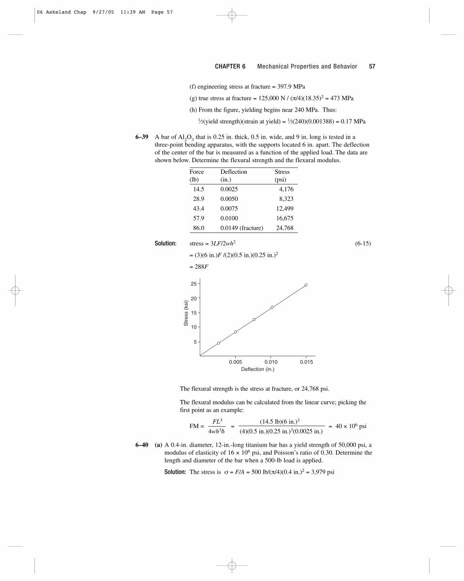
(f) engineering stress at fracture = 397.9 MPa
(g) true stress at fracture = 125,000 N / (π/4)(18.35)2 = 473 MPa
(h) From the figure, yielding begins near 240 MPa. Thus:
1⁄2(yield strength)(strain at yield) = 1⁄2(240)(0.001388) = 0.17 MPa
6–39 A bar of Al2O3 that is 0.25 in. thick, 0.5 in. wide, and 9 in. long is tested in a three-point bending apparatus, with the supports located 6 in. apart. The deflectionof the center of the bar is measured as a function of the applied load. The data areshown below. Determine the flexural strength and the flexural modulus.
Force Deflection Stress(lb) (in.) (psi)
14.5 0.0025 4,176
28.9 0.0050 8,323
43.4 0.0075 12,499
57.9 0.0100 16,675
86.0 0.0149 (fracture) 24,768
Solution: stress = 3LF/2wh2 (6-15)
= (3)(6 in.)F /(2)(0.5 in.)(0.25 in.)2
= 288F
The flexural strength is the stress at fracture, or 24,768 psi.
The flexural modulus can be calculated from the linear curve; picking thefirst point as an example:
FM = FL3
=(14.5 lb)(6 in.)3
= 40 × 106 psi4wh3δ (4)(0.5 in.)(0.25 in.)3(0.0025 in.)
6–40 (a) A 0.4-in. diameter, 12-in.-long titanium bar has a yield strength of 50,000 psi, amodulus of elasticity of 16 × 106 psi, and Poisson’s ratio of 0.30. Determine thelength and diameter of the bar when a 500-lb load is applied.
Solution: The stress is σ = F/A = 500 lb/(π/4)(0.4 in.)2 = 3,979 psi
5
10
15
20
25
0.005 0.010 0.015Deflection (in.)
Str
ess
(ksi
)
CHAPTER 6 Mechanical Properties and Behavior 57
06 Askeland Chap 9/27/05 11:39 AM Page 57
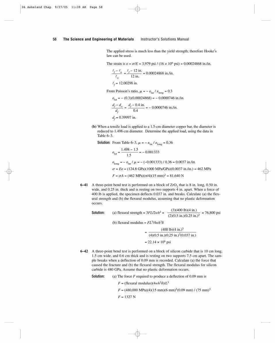
The applied stress is much less than the yield strength; therefore Hooke’slaw can be used.
The strain is e = s/E = 3,979 psi / (16 × 106 psi) = 0.00024868 in./in.
lf − lo =lf − 12 in.
= 0.00024868 in./in.lo 12 in.
lf = 12.00298 in.
From Poisson’s ratio, m = − elat / elong = 0.3
elat = − (0.3)(0.00024868) = − 0.0000746 in./in.
df − do = df − 0.4 in.
= − 0.0000746 in./in.df 0.4
df = 0.39997 in.
(b) When a tensile load is applied to a 1.5-cm diameter copper bar, the diameter isreduced to 1.498-cm diameter. Determine the applied load, using the data in Table 6–3.
Solution: From Table 6–3, m = − elat / elong = 0.36
elat =1.498 − 1.5
= − 0.0013331.5
elong = − elat / m = − (−0.001333) / 0.36 = 0.0037 in./in.
s = Ee = (124.8 GPa)(1000 MPa/GPa)(0.0037 in./in.) = 462 MPa
F = sA = (462 MPa)(π/4)(15 mm)2 = 81,640 N
6–41 A three-point bend test is performed on a block of ZrO2 that is 8 in. long, 0.50 in.wide, and 0.25 in. thick and is resting on two supports 4 in. apart. When a force of400 lb is applied, the specimen deflects 0.037 in. and breaks. Calculate (a) the flex-ural strength and (b) the flexural modulus, assuming that no plastic deformationoccurs.
Solution: (a) flexural strength = 3FL/2wh2 =(3)(400 lb)(4 in.)
= 76,800 psi(2)(0.5 in.)(0.25 in.)2
(b) flexural modulus = FL3/4wh3d
=(400 lb)(4 in.)3
(4)(0.5 in.)(0.25 in.)3(0.037 in.)
= 22.14 × 10⁶ psi
6–42 A three-point bend test is performed on a block of silicon carbide that is 10 cm long,1.5 cm wide, and 0.6 cm thick and is resting on two supports 7.5 cm apart. The sam-ple breaks when a deflection of 0.09 mm is recorded. Calculate (a) the force thatcaused the fracture and (b) the flexural strength. The flexural modulus for siliconcarbide is 480 GPa. Assume that no plastic deformation occurs.
Solution: (a) The force F required to produce a deflection of 0.09 mm is
F = (flexural modulus)(4wh3d)/L3
F = (480,000 MPa)(4)(15 mm)(6 mm)3(0.09 mm) / (75 mm)3
F = 1327 N
58 The Science and Engineering of Materials Instructor’s Solutions Manual
06 Askeland Chap 9/27/05 11:39 AM Page 58
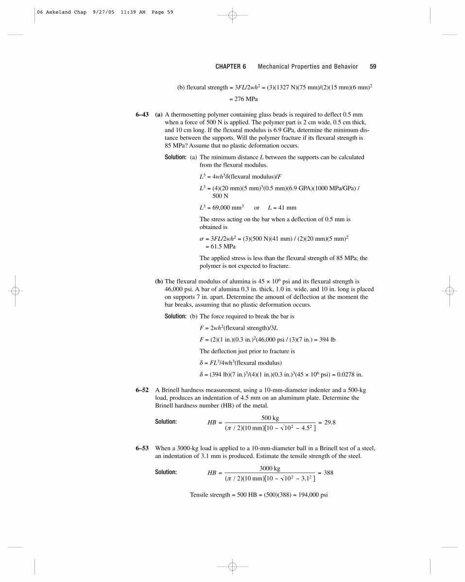
(b) flexural strength = 3FL/2wh2 = (3)(1327 N)(75 mm)/(2)(15 mm)(6 mm)2
= 276 MPa
6–43 (a) A thermosetting polymer containing glass beads is required to deflect 0.5 mmwhen a force of 500 N is applied. The polymer part is 2 cm wide, 0.5 cm thick,and 10 cm long. If the flexural modulus is 6.9 GPa, determine the minimum dis-tance between the supports. Will the polymer fracture if its flexural strength is 85 MPa? Assume that no plastic deformation occurs.
Solution: (a) The minimum distance L between the supports can be calculatedfrom the flexural modulus.
L3 = 4wh3d(flexural modulus)/F
L3 = (4)(20 mm)(5 mm)3(0.5 mm)(6.9 GPA)(1000 MPa/GPa) / 500 N
L3 = 69,000 mm3 or L = 41 mm
The stress acting on the bar when a deflection of 0.5 mm is obtained is
s = 3FL/2wh2 = (3)(500 N)(41 mm) / (2)(20 mm)(5 mm)2
= 61.5 MPa
The applied stress is less than the flexural strength of 85 MPa; thepolymer is not expected to fracture.
(b) The flexural modulus of alumina is 45 × 106 psi and its flexural strength is46,000 psi. A bar of alumina 0.3 in. thick, 1.0 in. wide, and 10 in. long is placedon supports 7 in. apart. Determine the amount of deflection at the moment thebar breaks, assuming that no plastic deformation occurs.
Solution: (b) The force required to break the bar is
F = 2wh2(flexural strength)/3L
F = (2)(1 in.)(0.3 in.)2(46,000 psi / (3)(7 in.) = 394 lb
The deflection just prior to fracture is
d = FL3/4wh3(flexural modulus)
d = (394 lb)(7 in.)3/(4)(1 in.)(0.3 in.)3(45 × 106 psi) = 0.0278 in.
6–52 A Brinell hardness measurement, using a 10-mm-diameter indenter and a 500-kgload, produces an indentation of 4.5 mm on an aluminum plate. Determine theBrinell hardness number (HB) of the metal.
Solution:
6–53 When a 3000-kg load is applied to a 10-mm-diameter ball in a Brinell test of a steel,an indentation of 3.1 mm is produced. Estimate the tensile strength of the steel.
Solution:
Tensile strength = 500 HB = (500)(388) = 194,000 psi
HB =− −
=3000
2 10 10 10 3 1388
2 2
kg
mm( / )( )[ . ]π
HB =− −
=500
2 10 10 10 4 529 8
2 2
kg
mm( / )( )[ . ].
π
CHAPTER 6 Mechanical Properties and Behavior 59
06 Askeland Chap 9/27/05 11:39 AM Page 59
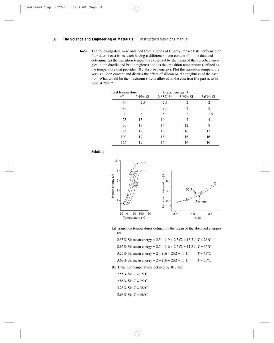
6–57 The following data were obtained from a series of Charpy impact tests performed onfour ductile cast irons, each having a different silicon content. Plot the data anddetermine (a) the transition temperature (defined by the mean of the absorbed ener-gies in the ductile and brittle regions) and (b) the transition temperature (defined asthe temperature that provides 10 J absorbed energy). Plot the transition temperatureversus silicon content and discuss the effect of silicon on the toughness of the castiron. What would be the maximum silicon allowed in the cast iron if a part is to beused at 25oC?
Test temperature Impact energy (J)oC 2.55% Si 2.85% Si 3.25% Si 3.63% Si
−50 2.5 2.5 2 2
−5 3 2.5 2 2
0 6 5 3 2.5
25 13 10 7 4
50 17 14 12 8
75 19 16 16 13
100 19 16 16 16
125 19 16 16 16
Solution:
(a) Transition temperatures defined by the mean of the absorbed energiesare:
2.55% Si: mean energy = 2.5 + (19 + 2.5)/2 = 13.2 J; T = 26oC
2.85% Si: mean energy = 2.5 + (16 + 2.5)/2 = 11.8 J; T = 35oC
3.25% Si: mean energy = 2 + (16 + 2)/2 = 11 J; T = 45oC
3.63% Si: mean energy = 2 + (16 + 2)/2 = 11 J; T = 65oC
(b) Transition temperatures defined by 10 J are:
2.55% Si: T = 15oC
2.85% Si: T = 25oC
3.25% Si: T = 38oC
3.63% Si: T = 56oC
50 J
Average20
40
60
2.5 3.0 3.5% Si
Tran
sitio
n Te
mpe
ratu
re (
°C)
Impa
ct e
nerg
y (J
) 2.55
%2.
85%
3.25
%3.
63%
4
8
12
16
20
−50 0 50 100 150Temperature (°C)
60 The Science and Engineering of Materials Instructor’s Solutions Manual
06 Askeland Chap 9/27/05 11:39 AM Page 60
Increasing the silicon decreases the toughness and increases the tran-sition temperature; silicon therefore reduces the impact properties of thecast iron.
If the part is to be used at 25oC, we would want a maximum of about2.9% Si in the cast iron.
6–58 FCC metals are often recommended for use at low temperatures, particularly whenany sudden loading of the part is expected. Explain.
Solution: FCC metals do not normally display a transition temperature; instead theimpact energies decrease slowly with decreasing temperature and, in atleast some cases (such as some aluminum alloys), the energies evenincrease at low temperatures. The FCC metals can obtain large ductili-ties, giving large areas beneath the true stress-strain curve.
6–59 A steel part can be made by powder metallurgy (compacting iron powder particlesand sintering to produce a solid) or by machining from a solid steel block. Whichpart is expected to have the higher toughness? Explain.
Solution: Parts produced by powder metallurgy often contain considerableamounts of porosity due to incomplete sintering; the porosity providessites at which cracks might easily nucleate. Parts machined from solidsteel are less likely to contain flaws that would nucleate cracks, thereforeimproving toughness.
6–62 A number of aluminum-silicon alloys have a structure that includes sharp-edgedplates of brittle silicon in the softer, more ductile aluminum matrix. Would youexpect these alloys to be notch-sensitive in an impact test? Would you expect thesealloys to have good toughness? Explain your answers.
Solution: The sharp-edged plates of the brittle silicon may act as stress-raisers, ornotches, thus giving poor toughness to the alloy. The presence of addi-tional notches, such as machining marks, will not have a significanteffect, since there are already very large numbers of “notches” due to themicrostructure. Consequently this type of alloy is expected to have poortoughness but is not expected to be notch sensitive.
CHAPTER 6 Mechanical Properties and Behavior 61
06 Askeland Chap 9/27/05 11:39 AM Page 61

06 Askeland Chap 9/27/05 11:39 AM Page 62
63
7Fracture Mechanics, Fatigue, and CreepBehaviour
7–1 Alumina (Al2O3) is a brittle ceramic with low toughness. Suppose that fibers of sili-con carbide (SiC), another brittle ceramic with low toughness, could be embeddedwithin the alumina. Would doing this affect the toughness of the ceramic matrixcomposite? Explain. (These materials are discussed in later chapters.)
Solution: The SiC fibers may improve the toughness of the alumina matrix. Thefibers may do so by several mechanisms. By introducing an interface(between the fibers and the matrix), a crack may be blocked; to continuegrowing, the crack may have to pass around the fiber, thus increasing thetotal energy of the crack and thus the energy that can be absorbed by thematerial. Or extra energy may be required to force the crack through theinterface in an effort to continue propagating. In addition, the fibers maybegin to pull out of the matrix, particularly if bonding is poor; the fiberpull-out requires energy, thus improving toughness. Finally, the fibersmay bridge across the crack, helping to hold the material together andrequiring more energy to propagate the crack.
7–2 A ceramic matrix composite contains internal flaws as large as 0.001 cm in length. The plane strain fracture toughness of the composite is 45 and the tensile strength is 550 MPa. Will the flaw cause the composite to fail before the tensilestrength is reached? Assume that f = 1.
Solution: Since the crack is internal, 2a = 0.001 cm = 0.00001 m. Therefore
a = 0.000005 m
s = =( ) / ( ) ( . ) ,45 1 0 000005 11 354MPa m m MPaπ
K f a K f aIc lc= =s sπ πor /
MPa m
07 Askeland Chap 9/27/05 11:42 AM Page 63

The applied stress required for the crack to cause failure is much largerthan the tensile strength of 550 MPa. Any failure of the ceramic shouldbe expected due to the massive overload, not because of the presence ofthe flaws.
7–3 An aluminum alloy that has a plane strain fracture toughness of 25,000 fails when a stress of 42,000 psi is applied. Observation of the fracture surface indi-cates that fracture began at the surface of the part. Estimate the size of the flaw thatinitiated fracture. Assume that f = 1.1.
Solution:
7–4 A polymer that contains internal flaws 1 mm in length fails at a stress of 25 MPa.Determine the plane strain fracture toughness of the polymer. Assume that f = 1.
Solution: Since the flaws are internal, 2a = 1 mm = 0.001 m; thus a = 0.0005 m
7–5 A ceramic part for a jet engine has a yield strength of 75,000 psi and a plane strain
fracture toughness of 5,000 To be sure that the part does not fail, we plan to assure that the maximum applied stress is only one third the yield strength. Weuse a nondestructive test that will detect any internal flaws greater than 0.05 in.long. Assuming that f = 1.4, does our nondestructive test have the required sensitivity? Explain.
Solution: The applied stress is s = (1⁄3)(75,000 psi) = 25,000 psi
a = (1/π)[KIc/fs]2 = (1/π)[5,000 / (1.4)(25,000 psi)]2
a = 0.0065 in.
The length of internal flaws is 2a = 0.013 in.
Our nondestructive test can detect flaws as small as 0.05 in. long, whichis not smaller than the critical flaw size required for failure. Thus ourNDT test is not satisfactory.
7–22 A cylindrical tool steel specimen that is 6 in. long and 0.25 in. in diameter rotates asa cantilever beam and is to be designed so that failure never occurs. Assuming thatthe maximum tensile and compressive stresses are equal, determine the maximumload that can be applied to the end of the beam. (See Figure 7–19.)
Solution: The stress must be less than the endurance limit, 60,000 psi.
s = 10.18LF/d3 or F = (endurance limit)d3/10.18L
F = (60,000 psi)(0.25 in.)3 / (10.18)(6 in.) = 15.35 lb
7–23 A 2-cm-diameter, 20-cm-long bar of an acetal polymer (Figure 7–29) is loaded onone end and is expected to survive one million cycles of loading, with equal maxi-mum tensile and compressive stresses, during its lifetime. What is the maximumpermissible load that can be applied?
Solution: From the figure, we find that the fatigue strength must be 22 MPa inorder for the polymer to survive one million cycles. Thus, the maximumload is
psi in.
psi in.
K f aIc = = =s π π( )( ) ( . ) .1 25 0 0005 0 99MPa m MPa m
a = =( / )[ , . / ( . )( , )] . .1 25 000 1 1 42 000 0 0932π psi in psi in
K f a or a K fIc lc= =s sπ π( / )[ / ]1 2
psi in.
64 The Science and Engineering of Materials Instructor’s Solutions Manual
07 Askeland Chap 9/27/05 11:42 AM Page 64
F = (fatigue strength)d3/10.18L
F = (22 MPa)(20 mm)3 / (10.18)(200 mm) = 86.4 N
7–24 A cyclical load of 1500 lb is to be exerted at the end of a 10-in.-long aluminumbeam (Figure 7–19). The bar must survive for at least 106 cycles. What is the mini-mum diameter of the bar?
Solution: From the figure, we find that the fatigue strength must be 35,000 psi inorder for the aluminum to survive 106 cycles. Thus, the minimum diame-ter of the bar is
7–25 A cylindrical acetal polymer bar 20 cm long and 1.5 cm in diameter is subjected to avibrational load at a frequency of 500 vibrations per minute with a load of 50 N.How many hours will the part survive before breaking? (See Figure 7–29)
Solution: The stress acting on the polymer is
s = 10.18LF/d3 = (10.18)(200 mm)(50 N) / (15 mm)3 = 30.16 MPa
From the figure, the fatigue life at 30.16 MPa is about 2 × 10⁵ cycles.Based on 500 cycles per minute, the life of the part islife = 2 × 10⁵ cycles / (500 cycles/min)(60 min/h) = 6.7 h
7–26 Suppose that we would like a part produced from the acetal polymer shown inFigure 7–29 to survive for one million cycles under conditions that provide for equalcompressive and tensile stresses. What is the fatigue strength, or maximum stressamplitude, required? What are the maximum stress, the minimum stress, and themean stress on the part during its use? What effect would the frequency of the stressapplication have on your answers? Explain.
Solution: From the figure, the fatigue strength at one million cycles is 22 MPa.
The maximum stress is +22 MPa, the minimum stress is −22 MPa, andthe mean stress is 0 MPa.
A high frequency will cause heating of the polymer. As the temperatureof the polymer increases, the fatigue strength will decrease. If theapplied stress is not reduced, then the polymer will fail in a shorter time.
7–27 The high-strength steel in Figure 7–21 is subjected to a stress alternating at 200revolutions per minute between 600 MPa and 200 MPa (both tension). Calculate thegrowth rate of a surface crack when it reaches a length of 0.2 mm in both m/cycleand m/s. Assume that f = 1.0.
Solution: For the steel, C = 1.62 × 10⁻¹² and n = 3.2. The change in the stressintensity factor ∆K is
The crack growth rate is
da/dN = 1.62 × 10⁻¹²(∆K)3.2
da/dN = 1.62 × 10⁻¹²(12.03)3.2 = 4.638 × 10⁻⁹ m/cycle
∆ ∆K f a− = − =s π π( . )( ) ( . .1 2 600 200 0 0002 12 03MPa MPa m) MPa m
d = =3 10 18 10 1500 35 000 1 634( . )( .)( ) / , . .in lb psi in
d LF= 3 10 18. / fatiguestrength
CHAPTER 7 Fracture Mechanics, Fatigue, and Creep Behaviour 65
07 Askeland Chap 9/27/05 11:42 AM Page 65
da/dt = (4.638 × 10⁻⁹ m/cycle)(200 cycles/min)/ 60 s/min
da/dt = 1.55 × 10⁻⁸ m/s
7–28 The high-strength steel in Figure 7–21, which has a critical fracture toughness of 80 is subjected to an alternating stress varying from −900 MPa (compres-sion) to +900 MPa (tension). It is to survive for 105 cycles before failure occurs.Calculate (a) the size of a surface crack required for failure to occur and (b) thelargest initial surface crack size that will permit this to happen. Assume that f = 1.
Solution: (a) Only the tensile portion of the applied stress is considered in ∆s.Based on the applied stress of 900 MPa and the fracture toughness of 80 the size of a surface crack required for failure tooccur is
(b) The largest initial surface crack tolerable to prevent failure within 105
cycles is
N = 105 cycles =2[(0.0025 m)(2−3.2)/2 − ai
(2−3.2)/2]
(2 − 3.2)(1.62 × 10⁻¹²)(1)3.2(900)3.2(π)3.2/2
105 =2[36.41 − (ai)
−0.60]
(−1.2)(1.62 × 10⁻¹²)(1)(2.84 × 10⁹)(6.244)
(ai)−0 6 = 1760
ai = 3.9 × 10⁻⁶ m = 0.0039 mm
7–29 The acrylic polymer from which Figure 7–30 was obtained has a critical fracture
toughness of 2 It is subjected to a stress alternating between −10 and +10 MPa. Calculate the growth rate of a surface crack when it reaches a length of 5 × 10⁻⁶ m if f = 1.0.
Solution: ∆s = 10 MPa − 0 = 10 MPa, since the crack doesn’t propagate forcompressive loads.
From the graph, da/dN = 3 × 10⁻⁷ m/cycle
7–30 Calculate the constants “C” and “n” is the Equation 7–18 for the crack growth rateof an acrylic polymer. (See Figure 7–30.)
Solution: Let’s pick two points on the graph:
2 × 10−6
=C(0.1)n
1 × 10⁻⁷ C(0.037)n
20 = (0.1 / 0.037)n = (2.703)n
ln(20) = n ln(2.703) 2.9957 = 0.994n n = 3.01
2 × 10−6 = C(0.1)3.01 = 0.000977C C = 2.047 × 10⁻³
da dN K/ / .= × =−1 10 0 0377 m cycle when MPa m∆
da dN K/ / .= × =−2 10 0 16 m cycle when MPa m∆
∆ ∆K f a− = × =−σ π π( . )( ) ( ) .1 3 10 5 10 0 05156MPa m MPa m
MPa m .
ac = = =( / )[ / ( )( )] . .1 80 1 900 0 0025 2 52π MPa m MPa m mm
K f a a K fc c= =s sπ πor ( / )[ / ]1 2
MPa m ,
MPa m ,
66 The Science and Engineering of Materials Instructor’s Solutions Manual
07 Askeland Chap 9/27/05 11:42 AM Page 66

7–31 The acrylic polymer from which Figure 7–30 was obtained is subjected to an alter-nating stress between 15 MPa and 0 MPa. The largest surface cracks initiallydetected by nondestructive testing are 0.001 mm in length. If the critical fracture
toughness of the polymer is 2 calculate the number of cycles requiredbefore failure occurs. Let f = 1.0. (Hint: Use the results of Problem 7–30.)
Solution: From Problem 7–30, C = 2.047 × 10⁻³ and n = 3.01
The critical flaw size ac is
ac = (1/π)[KIc / fs]2 = (1/π)[(2 / (1.2)(15 MPa)]2
ac = 0.00393 m = 3.93 mm
Then
N =2[(0.00393 m)(2−3.01)/2 − (0.000001 m)(2−3.01)/2]
(2−3.01)(2.047 × 10⁻³)(1.2)3.01(15 mPa)3.01(π)3.01/2
N =2(16.3995 − 1071.52)
= 30.36 cycles(−1.01)(2.047 × 10⁻³)(1.7312)(3467.65)(5.6)
7–33 Verify that integration of da/dN = C(∆K)n will give Equation 7–20.
Solution: dN = (1/cf n∆snπn/2)(da/an/2) or N = (1/cf n∆snπn/2) ∫ (da/an/2)
since ∫ apda = [1/(1 + p)](ap + 1)
then if p = −n/2, ∫ da/an/2 =1
[a−n/2 + 1]aiac = (2/2 − n)[ac
(2−n)/2 − ai(2−n)/2]
1 − n/2
thus N = 2[ac
(2−n)/2 − ai(2−n)/2]
(2−n)cf n∆σnπn/2
7–38 The activation energy for self-diffusion in copper is 49,300 cal/mol. A copper speci-men creeps at 0.002 in./in. � h when a stress of 15,000 psi is applied at 600oC. If thecreep rate of copper is dependent on self-diffusion, determine the creep rate if thetemperature is 800oC.
Solution: The creep rate is governed by an Arrhenius relationship of the form rate= A exp(−Q/RT). From the information given,
x=
A exp[−49,300/(1.987)(800 + 273)]=
9.07 × 10⁻¹¹
0.002 in./in. � h A exp[−49,300/(1.987)(600 + 273)] 4.54 × 10⁻¹³
x = (0.002)(9.07 × 10⁻¹¹ / 4.54 × 10⁻¹³) = 0.4 in./in. � h
7–39 When a stress of 20,000 psi is applied to a material heated to 900oC, rupture occursin 25,000 h. If the activation energy for rupture is 35,000 cal/mol, determine therupture time if the temperature is reduced to 800oC.
Solution: The rupture time is related to temperature by an Arrhenius relationshipof the form tr = A exp(+Q/RT); the argument of the exponential is posi-tive because the rupture time is inversely related to the rate. From theinformation given
tr =A exp[35,000/(1.987)(800+273)]
=1.35 × 10⁷
25,000 h A exp[35,000/(1.987)(900+273)] 3.32 × 10⁶
tr = (25,000)(1.35 × 10⁷ / 3.32 × 10⁶) = 101,660 h
MPa m )
MPa m ,
CHAPTER 7 Fracture Mechanics, Fatigue, and Creep Behaviour 67
07 Askeland Chap 9/27/05 11:42 AM Page 67
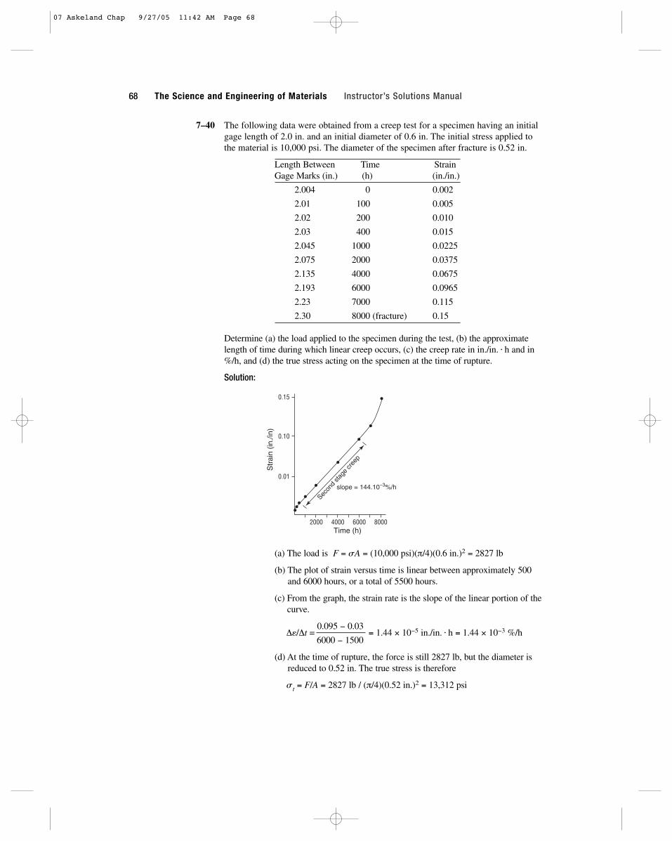
7–40 The following data were obtained from a creep test for a specimen having an initialgage length of 2.0 in. and an initial diameter of 0.6 in. The initial stress applied tothe material is 10,000 psi. The diameter of the specimen after fracture is 0.52 in.
Length Between Time StrainGage Marks (in.) (h) (in./in.)
2.004 0 0.002
2.01 100 0.005
2.02 200 0.010
2.03 400 0.015
2.045 1000 0.0225
2.075 2000 0.0375
2.135 4000 0.0675
2.193 6000 0.0965
2.23 7000 0.115
2.30 8000 (fracture) 0.15
Determine (a) the load applied to the specimen during the test, (b) the approximatelength of time during which linear creep occurs, (c) the creep rate in in./in. � h and in%/h, and (d) the true stress acting on the specimen at the time of rupture.
Solution:
(a) The load is F = sA = (10,000 psi)(π/4)(0.6 in.)2 = 2827 lb
(b) The plot of strain versus time is linear between approximately 500and 6000 hours, or a total of 5500 hours.
(c) From the graph, the strain rate is the slope of the linear portion of thecurve.
∆e/∆t =0.095 − 0.03
= 1.44 × 10⁻⁵ in./in. � h = 1.44 × 10⁻³ %/h 6000 − 1500
(d) At the time of rupture, the force is still 2827 lb, but the diameter isreduced to 0.52 in. The true stress is therefore
st = F/A = 2827 lb / (π/4)(0.52 in.)2 = 13,312 psi
Secon
d sta
ge cr
eep
slope = 144.10−3%/h
Str
ain
(in./i
n)
0.01
0.10
0.15
2000 4000 6000 8000Time (h)
68 The Science and Engineering of Materials Instructor’s Solutions Manual
07 Askeland Chap 9/27/05 11:42 AM Page 68

7–41 A stainless steel is held at 705oC under different loads. The following data areobtained:
Applied Stress (MPa) Rupture Time (h) Creep Rate (%/h)
106.9 1200 0.022
128.2 710 0.068
147.5 300 0.201
160.0 110 0.332
Determine the exponents “n” and “m” in Equations 7–22 and 7–23 that describe thedependence of creep rate and rupture time on applied stress.
Solution: Plots describing the effect of applied stress on creep rate and on rupturetime are shown below. In the first plot, the creep rate is given by ∆e/∆t= Csn and the graph is a log-log plot. In the second plot, rupturetime is given by tr = A sm, another log-log plot.
The exponents “n” and “m” are the slopes of the two graphs. In this case,
n = 6.86 m = −6.9
7–42 Using the data in Figure 7–27 for an iron-chromium-nickel alloy, determine the acti-vation energy Qr and the constant “m” for rupture in the temperature range 980 to1090oC.
Solution: The appropriate equation is tr = Ksmexp(Qr/RT).
From Figure 7–27(a), we can determine the rupture time versus temperature for a fixed stress, say s = 1000 psi:
tr = 2,400 h at 1090oC = 1363 K
tr = 14,000 h at 1040oC = 1313 K
tr = 100,000 h at 980oC = 1253 K
From this data, the equation becomes tr = K′exp(Qr/RT) and we can find Qr by simultaneous equations or graphically.
Qr = 117,000 cal/mol
0.01
0.02
0.03
0.04
0.06
0.10
0.20
0.30
0.40
100 200 300Stress (MPa)
Cre
ep r
ate
(%/h
)
slope = 6.86
∆ε∆t = Cσ6.86
100
200
400
600
1000
2000
100 200 300Stress (MPa)
Rup
ture
tim
e (h
)
slope = −6.9
tr = Aσ−6.9
CHAPTER 7 Fracture Mechanics, Fatigue, and Creep Behaviour 69
07 Askeland Chap 9/27/05 11:42 AM Page 69

We can also determine the rupture time versus applied stress for a con-stant temperature, say 1090oC:
tr = 105 h for s = 450 psi
tr = 104 h for s = 800 psi
tr = 103 h for s = 1200 psi
tr = 102 h for s = 2100 psi
With this approach, the equation becomes tr = K″σm, where “m” is obtained graphically or by simultaneous equations:
m = 3.9
7–43 A 1-in.-diameter bar of an iron-chromium-nickel alloy is subjected to a load of 2500 lb. How many days will the bar survive without rupturing at 980oC? [SeeFigure 7–27(a).]
Solution: The stress is s = F/A = 2500 lb / (π/4)(1 in.)2 = 3183 psi
From the graph, the rupture time is 700 h / 24 h/day = 29 days
7–44 A 5 mm × 20 mm bar of an iron-chromium-nickel alloy is to operate at 1040oC for10 years without rupturing. What is the maximum load that can be applied? [SeeFigure 7–27(a).]
Solution: The operating time is (10 years)(365 days/year)(24 h/day) = 87,600 h
From the graph, the stress must be less than 500 psi. The load is then
F = sA = (500 psi)(5 mm/25.4 mm/in.)(20 mm/25.4 mm/in.) = 77.5 lb
7–45 An iron-chromium-nickel alloy is to withstand a load of 1500 lb at 760oC for 6years. Calculate the minimum diameter of the bar. [See Figure 7–27(a).]
Solution: The operating time is (6 years)(365 days/year)(24 h/day) = 52,560 h
From the graph, the stress must be less than 7000 psi. The minimumdiameter of the bar is then
d F= = =( / )( / ( / )( / ) . .4 4 1500 7000 0 52π πs lb psi in
105
104
103
Rup
ture
tim
e (h
)
In 1
05 – In
104
0.000796 – 0.000757
Q/R = 59,000
Q = 117,000 cal/mol
0.00074 0.00076 0.00078 0.00080
I/T (K−1)
102
102 103 104
103
104
105
Stress (psi)R
uptu
re ti
me
(h)
m = 3.9
70 The Science and Engineering of Materials Instructor’s Solutions Manual
07 Askeland Chap 9/27/05 11:42 AM Page 70
7–46 A 1.2-in.-diameter bar of an iron-chromium-nickel alloy is to operate for 5 yearsunder a load of 4000 lb. What is the maximum operating temperature? [See Figure7–27(a).]
Solution: The operating time is (5 years)(365 days/year)(24 h/day) = 43,800 h
The stress is s = F/A = 4000 lb / (π/4)(1.2 in.)2 = 3537 psi
From the figure, the temperature must be below 850oC in order for thebar to survive five years at 3537 psi.
7–47 A 1 in. × 2 in. ductile cast iron bar must operate for 9 years at 650oC. What is themaximum load that can be applied? [See Figure 7–27(b).]
Solution: The operating time is (9 year)(365 days/year)(24 h/day) = 78,840 h.
The temperature is 650 + 273 = 923 K
LM = (923/1000)[36 + 0.78 ln(78,840)] = 41.35
From the graph, the stress must be no more than about 1000 psi. The load is then
F = sA = (1000 psi)(2 in.2) = 2000 lb
7–48 A ductile cast iron bar is to operate at a stress of 6000 psi for 1 year. What is themaximum allowable temperature? [See Figure 7–27(b).]
Solution: The operating time is (1 year)(365 days/year)(24 h/day) = 8760 h
From the graph, the Larson-Miller parameter must be 34.4 at a stress of6000 psi. Thus
34.4 = (T / 1000)[36 + 0.78 ln(8760)] = 0.043T
T = 800 K = 527oC
CHAPTER 7 Fracture Mechanics, Fatigue, and Creep Behaviour 71
07 Askeland Chap 9/27/05 11:42 AM Page 71

07 Askeland Chap 9/27/05 11:42 AM Page 72
73
8Strain Hardening and Annealing
8–5 A 0.505-in.-diameter metal bar with a 2-in. gage length l0 is subjected to a tensiletest. The following measurements are made in the plastic region:
Change inForce (lb) Gage length (in.) (∆l) Diameter (in.)
27,500 0.2103 0.4800
27,000 0.4428 0.4566
25,700 0.6997 0.4343
Determine the strain-hardening exponent for the metal. Is the metal most likely to beFCC, BCC, or HCP? Explain.
Solution:
Gage True TrueForce length Diameter stress strain
(lb) (in.) (in.) (psi) (in./in.)
27,500 2.2103 0.4800 151,970 0.100
27,000 2.4428 0.4566 164,893 0.200
25,700 2.6997 0.4343 173,486 0.300
st = Ketn or ln s = ln K + n ln e
ln(151,970) = ln K + n ln(0.1) 11.9314 = ln K − n (2.3026)
ln(173,486) = ln K + n ln(0.3) 12.0639 = ln K − n (1.2040)
−0.1325 = −1.0986 n
n = 0.12 which is in the range of BCC metals
08 Askeland Chap 9/27/05 11:44 AM Page 73
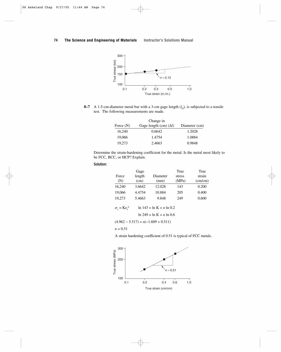
8–7 A 1.5-cm-diameter metal bar with a 3-cm gage length (l0), is subjected to a tensiletest. The following measurements are made.
Change inForce (N) Gage length (cm) (∆l) Diameter (cm)
16,240 0.6642 1.2028
19,066 1.4754 1.0884
19,273 2.4663 0.9848
Determine the strain-hardening coefficient for the metal. Is the metal most likely tobe FCC, BCC, or HCP? Explain.
Solution:
Gage True TrueForce length Diameter stress strain
(N) (cm) (mm) (MPa) (cm/cm)
16,240 3.6642 12.028 143 0.200
19,066 4.4754 10.884 205 0.400
19,273 5.4663 9.848 249 0.600
st = Ketn ln 143 = ln K + n ln 0.2
ln 249 = ln K + n ln 0.6
(4.962 − 5.517) = n(−1.609 + 0.511)
n = 0.51
A strain hardening coefficient of 0.51 is typical of FCC metals.
n = 0.51
Tru
e st
ress
(M
Pa)
100
200
300
0.1 0.2 0.4 0.6 1.0
True strain (cm/cm)
100
150
200
300
0.1 0.2 0.3 0.5 1.0
True strain (in./in.)
Tru
e st
ress
(ks
i)
n = 0.12
74 The Science and Engineering of Materials Instructor’s Solutions Manual
08 Askeland Chap 9/27/05 11:44 AM Page 74
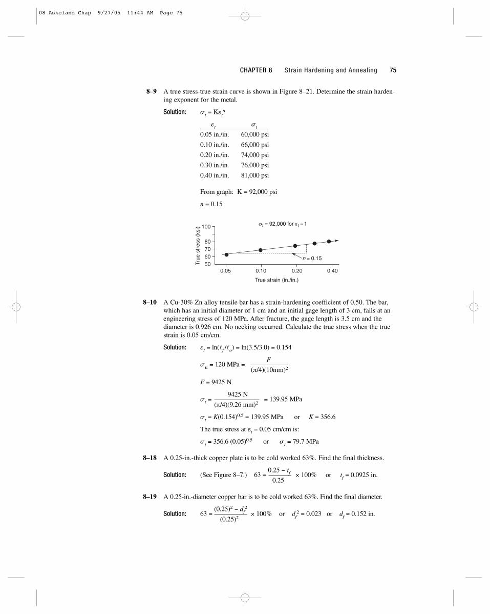
8–9 A true stress-true strain curve is shown in Figure 8–21. Determine the strain harden-ing exponent for the metal.
Solution: st = Ketn
et st
0.05 in./in. 60,000 psi
0.10 in./in. 66,000 psi
0.20 in./in. 74,000 psi
0.30 in./in. 76,000 psi
0.40 in./in. 81,000 psi
From graph: K = 92,000 psi
n = 0.15
8–10 A Cu-30% Zn alloy tensile bar has a strain-hardening coefficient of 0.50. The bar,which has an initial diameter of 1 cm and an initial gage length of 3 cm, fails at anengineering stress of 120 MPa. After fracture, the gage length is 3.5 cm and thediameter is 0.926 cm. No necking occurred. Calculate the true stress when the truestrain is 0.05 cm/cm.
Solution: et = ln(lf /lo) = ln(3.5/3.0) = 0.154
sE = 120 MPa =F
(π/4)(10mm)2
F = 9425 N
st =9425 N
= 139.95 MPa(π/4)(9.26 mm)2
st = K(0.154)0.5 = 139.95 MPa or K = 356.6
The true stress at et = 0.05 cm/cm is:
st = 356.6 (0.05)0.5 or st = 79.7 MPa
8–18 A 0.25-in.-thick copper plate is to be cold worked 63%. Find the final thickness.
Solution: (See Figure 8–7.) 63 =0.25 − tf × 100% or tf = 0.0925 in.
0.25
8–19 A 0.25-in.-diameter copper bar is to be cold worked 63%. Find the final diameter.
Solution: 63 =(0.25)2 − df
2
× 100% or df2 = 0.023 or df = 0.152 in.
(0.25)2
50607080
100
True
str
ess
(ksi
)
True strain (in./in.)
0.05 0.10 0.20 0.40
σt = 92,000 for εt = 1
n = 0.15
CHAPTER 8 Strain Hardening and Annealing 75
08 Askeland Chap 9/27/05 11:44 AM Page 75
8–20 A 2-in.-diameter copper rod is reduced to 1.5 in. diameter, then reduced again to afinal diameter of 1 in. In a second case, the 2-in.-diameter rod is reduced in one stepfrom 2 in. to a 1 in. diameter. Calculate the % CW for both cases.
Solution: % CW =(2)2 − (1)2
× 100 = 75% in both cases(2)2
8–21 A 3105 aluminum plate is reduced from 1.75 in. to 1.15 in. Determine the finalproperties of the plate. (See Figure 8–22.)
Solution: % CW =1.75 − 1.15
× 100% = 34.3%1.75
TS = 24 ksi YS = 22 ksi % elongation = 5%
8–22 A Cu-30% Zn brass bar is reduced from 1-in. diameter to a 0.45-in. diameter.Determine the final properties of the bar. (See Figure 8–23.)
Solution: % CW =(1)2 − (0.45)2
× 100 = 79.75%(1)2
TS = 105 ksi YS = 68 ksi % elongation = 1%
8–23 A 3105 aluminum bar is reduced from a 1-in. diameter, to a 0.8-in. diameter, to a0.6-in. diameter, to a final 0.4-in. diameter. Determine the % CW and the propertiesafter each step of the process. Calculate the total percent cold work. (See Figure 8–22.)
Solution: If we calculated the percent deformation in each step separately, wewould find that 36% deformation is required to go from 1 in. to 0.8 in.The deformation from 0.8 in. to 0.6 in. (using 0.8 in. as the initial diame-ter) is 43.75%, and the deformation from 0.6 in. to 0.4 in. (using 0.6 in.as the initial diameter) is 55.6%. If we added these three deformations,the total would be 135.35%. This would not be correct. Instead, we must always use the original 1 in. diameter as our starting point. The following table summarizes the actual deformation and properties aftereach step.
TS YS %ksi ksi elongation
(1)2 − (0.8)2
× 100 = 36% 26 23 6(1)2
(1)2 − (0.6)2
× 100 = 64% 30 27 3(1)2
(1)2 − (0.4)2
× 100 = 84% 32 29 2(1)2
The total percent cold work is actually 84%, not the 135.35%.
8–24 We want a copper bar to have a tensile strength of at least 70,000 psi and a finaldiameter of 0.375 in. What is the minimum diameter of the original bar? (See Figure 8–7.)
Solution: % CW ≥ 50% to achieve the minimum tensile strength
76 The Science and Engineering of Materials Instructor’s Solutions Manual
08 Askeland Chap 9/27/05 11:44 AM Page 76

50 =do
2 − (0.375)2
× 100do
2
0.5 do2 = 0.140625 or do = 0.53 in.
8–25 We want a Cu-30% Zn brass plate originally 1.2-in. thick to have a yield strengthgreater than 50,000 psi and a % elongation of at least 10%. What range of finalthicknesses must be obtained? (See Figure 8–23.)
Solution: YS > 50,000 psi requires CW > 20%
% E > 10% requires CW < 35%
1.2 − tf= 0.20
1.2 − tf= 0.35
1.2 1.2
tf = 0.96 in. tf = 0.78 in.
tf = 0.78 to 0.96 in.
8–26 We want a copper sheet to have at least 50,000 psi yield strength and at least 10%elongation, with a final thickness of 0.12 in. What range of original thicknessesmust be used? (See Figure 8–7.)
Solution: YS > 50 ksi requires CW ≥ 25%
% E > 10% requires CW ≤ 30%
to − 0.12 = 0.25
to − 0.12= 0.30
to to
to = 0.16 in. to = 0.17 in.
to = 0.16 to 0.17 in.
8–27 A 3105 aluminum plate previously cold worked 20% is 2-in. thick. It is then coldworked further to 1.3 in. Calculate the total percent cold work and determine thefinal properties of the plate? (See Figure 8–22.)
Solution: The original thickness (before the 20% cold work) must have been:
to − 2 = 0.20 to = 2.5 in.
to
The total cold work is then based on the prior 2.5 in. thickness:
CW =2.5 − 1.3
× 100% = 48%TS = 28 ksi
2.5 YS = 25 ksi
%E = 4%
8–28 An aluminum-lithium (Al-Li) strap 0.25-in. thick and 2-in. wide is to be cut from arolled sheet, as described in Figure 8–10. The strap must be able to support a35,000-lb load without plastic deformation. Determine the range of orientationsfrom which the strap can be cut from the rolled sheet.
Solution: s =35,000
≥ 70,000 psi(0.25)(2)
The properties can be obtained at angles of 0 to 20o from the rolling direction of the sheet.
CHAPTER 8 Strain Hardening and Annealing 77
08 Askeland Chap 9/27/05 11:44 AM Page 77
8–42 We want to draw a 0.3-in.-diameter copper wire having a yield strength of 20,000 psi into 0.25-in.-diameter wire. (a) Find the draw force, assuming no friction.(b) Will the drawn wire break during the drawing process? Show why. (SeeFigure 8–7.)
Solution: (a) Before drawing (0% CW), the yield strength is 20 ksi = 20,000 psi.
CW =(0.3)2 − (0.25)2
= 30.6%which gives YS = 53,000 psi
(0.3)2 in the drawn wire
(b) The force needed to draw the original wire is :
20,000 psi = F/(π/4)(0.3)2 or F = 1414 lb
(c) The stress acting on the drawn wire is:
s = 1414/(π/4)(0.25)2 = 28,806 psi < 53,000 psi
Since the actual stress (28,806 psi) acting on the drawn wire is less than the yield strength (53,000 psi) of the drawn wire, the wire will not break during manufacturing.
8–43 A 3105 aluminum wire is to be drawn to give a 1-mm-diameter wire having a yieldstrength of 20,000 psi. (a) Find the original diameter of the wire, (b) calculate thedraw force required, and (c) determine whether the as-drawn wire will break duringthe process. (See Figure 8–22.)
Solution: (a) We need to cold work 25% to obtain the required yield strength:
(b) The initial yield strength of the wire (with 0% cold work) is 8000 psi, so the force required to deform the initial wire is:
F = 8000[(π/4)(0.04546)2] = 12.98 lb
(c) The stress acting on the drawn wire (which has a smaller diameterbut is subjected to the same drawing force) is:
s =12.98 lb
= 10,662 psi < 20,000 psi(π/4)(1 mm/25.4 mm/in)2
Since the actual stress is less than the 20,000 psi yield strength of the drawn wire, the process will be successful and the wire will notbreak.
8–52 A titanium alloy contains a very fine dispersion of tiny Er2O3 particles. What will bethe effect of these particles on the grain growth temperature and the size of thegrains at any particular annealing temperature? Explain.
Solution: These particles, by helping pin the grain boundaries, will increase the grain growth temperature and decrease the grain size.
8–54 The following data were obtained when a cold-worked metal was annealed. (a) Estimate the recovery, recrystallization, and grain growth temperatures. (b) Recommend a suitable temperature for a stress-relief heat treatment. (c) Recommend a suitable temperature for a hot-working process. (d) Estimate the melting temperature of the alloy.
d
ddo
oo mm in
2 2
2
10 25 1 0 75 1 1547 0 04546
−= = = =. / . . . .
78 The Science and Engineering of Materials Instructor’s Solutions Manual
08 Askeland Chap 9/27/05 11:44 AM Page 78

Annealing Electrical Yield GrainTemperature Conductivity Strength Size
(oC) (ohm−1 � cm−1) (MPa) (mm)
400 3.04 × 10⁵ 86 0.10
500 3.05 × 10⁵ 85 0.10
600 3.36 × 10⁵ 84 0.10
700 3.45 × 10⁵ 83 0.098
800 3.46 × 10⁵ 52 0.030
900 3.46 × 10⁵ 47 0.031
1000 3.47 × 10⁵ 44 0.070
1100 3.47 × 10⁵ 42 0.120
Solution: (a) recovery temperature ≈ 550oC recrystallization temperature ≅ 750oCgrain growth temperature ≅ 950oC
(b) Stress relief temperature = 700oC
(c) Hot working temperature = 900oC
(d) 0.4 Tmp ≅ 750oC = 1023 KTmp ≅ 1023 / 0.4 = 2558 K = 2285oC
8–55 The following data were obtained when a cold-worked metal was annealed. (a) Estimate the recovery, recrystallization, and grain growth temperatures. (b) Recommend a suitable temperature for obtaining a high-strength, high-electricalconductivity wire. (c) Recommend a suitable temperature for a hot-working process.(d) Estimate the melting temperature of the alloy.
Pro
pert
ies
Temperature (°C)
400 600 800 1000 1200
Electricalconductivity
Grainsize
Yield strength
CHAPTER 8 Strain Hardening and Annealing 79
08 Askeland Chap 9/27/05 11:44 AM Page 79
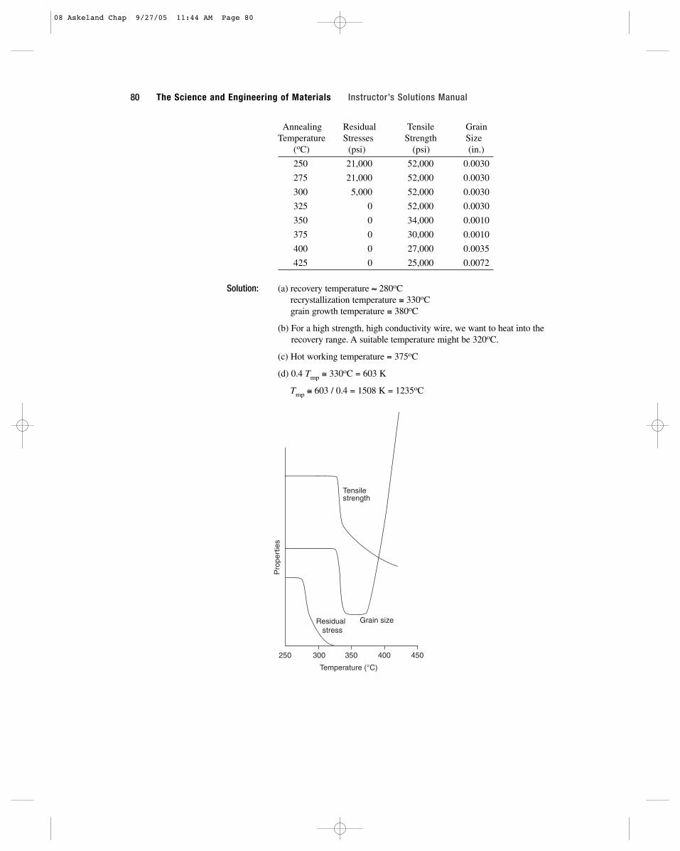
Annealing Residual Tensile GrainTemperature Stresses Strength Size
(oC) (psi) (psi) (in.)
250 21,000 52,000 0.0030
275 21,000 52,000 0.0030
300 5,000 52,000 0.0030
325 0 52,000 0.0030
350 0 34,000 0.0010
375 0 30,000 0.0010
400 0 27,000 0.0035
425 0 25,000 0.0072
Solution: (a) recovery temperature ≈ 280oCrecrystallization temperature ≅ 330oCgrain growth temperature ≅ 380oC
(b) For a high strength, high conductivity wire, we want to heat into therecovery range. A suitable temperature might be 320oC.
(c) Hot working temperature = 375oC
(d) 0.4 Tmp ≅ 330oC = 603 K
Tmp ≅ 603 / 0.4 = 1508 K = 1235oC
Pro
pert
ies
Temperature (°C)
250 300 350 400 450
Residual stress
Tensilestrength
Grain size
80 The Science and Engineering of Materials Instructor’s Solutions Manual
08 Askeland Chap 9/27/05 11:44 AM Page 80
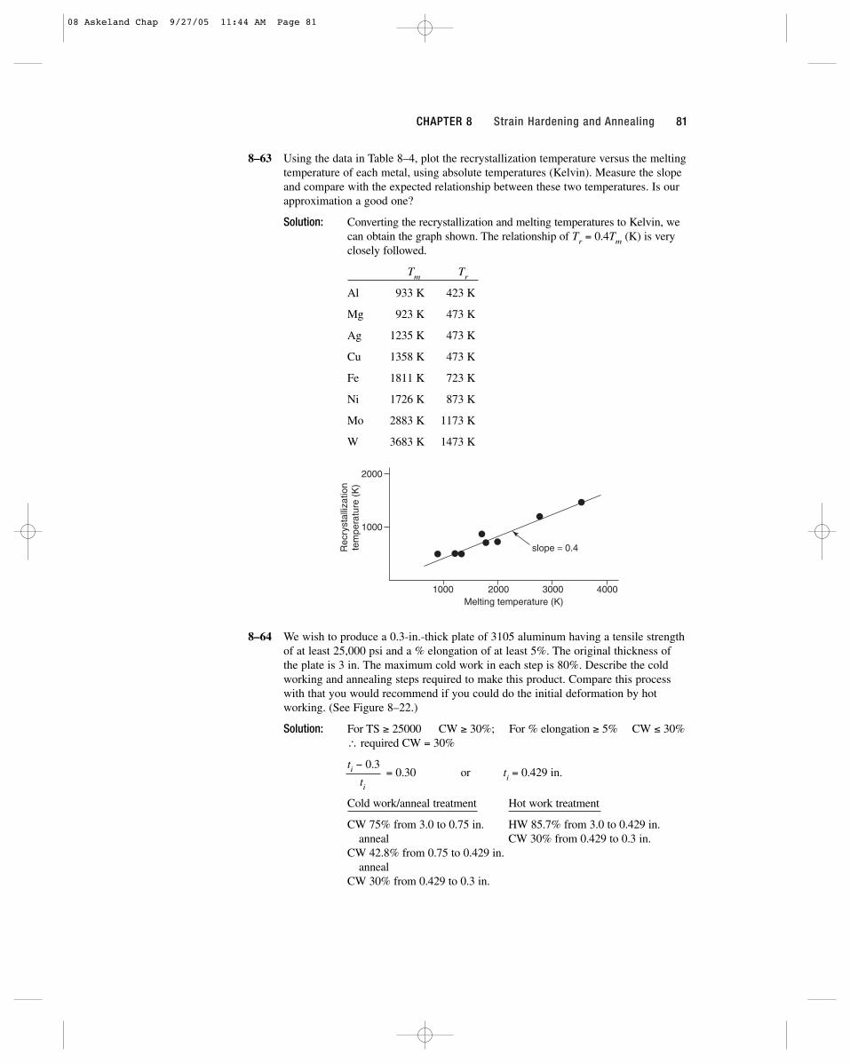
8–63 Using the data in Table 8–4, plot the recrystallization temperature versus the meltingtemperature of each metal, using absolute temperatures (Kelvin). Measure the slopeand compare with the expected relationship between these two temperatures. Is ourapproximation a good one?
Solution: Converting the recrystallization and melting temperatures to Kelvin, we can obtain the graph shown. The relationship of Tr = 0.4Tm (K) is veryclosely followed.
Tm Tr
Al 933 K 423 K
Mg 923 K 473 K
Ag 1235 K 473 K
Cu 1358 K 473 K
Fe 1811 K 723 K
Ni 1726 K 873 K
Mo 2883 K 1173 K
W 3683 K 1473 K
8–64 We wish to produce a 0.3-in.-thick plate of 3105 aluminum having a tensile strengthof at least 25,000 psi and a % elongation of at least 5%. The original thickness ofthe plate is 3 in. The maximum cold work in each step is 80%. Describe the coldworking and annealing steps required to make this product. Compare this processwith that you would recommend if you could do the initial deformation by hotworking. (See Figure 8–22.)
Solution: For TS ≥ 25000 CW ≥ 30%; For % elongation ≥ 5% CW ≤ 30% ∴ required CW = 30%
ti − 0.3 = 0.30 or ti = 0.429 in.
ti
Cold work/anneal treatment Hot work treatment
CW 75% from 3.0 to 0.75 in. HW 85.7% from 3.0 to 0.429 in.anneal CW 30% from 0.429 to 0.3 in.
CW 42.8% from 0.75 to 0.429 in.anneal
CW 30% from 0.429 to 0.3 in.
2000
1000
1000 2000 3000 4000Melting temperature (K)
Rec
ryst
alliz
atio
nte
mpe
ratu
re (
K)
slope = 0.4
CHAPTER 8 Strain Hardening and Annealing 81
08 Askeland Chap 9/27/05 11:44 AM Page 81

8–65 We wish to produce a 0.2-in. diameter wire of copper having a minimum yieldstrength of 60,000 psi and a minimum % elongation of 5%. The original diameter ofthe rod is 2 in. and the maximum cold work in each step is 80%. Describe the coldworking and annealing steps required to make this product. Compare this processwith that you would recommend if you could do the initial deformation by hotworking. (See Figure 8–7.)
Solution: For YS > 60 ksi, CW ≥ 40%; For % elongation > 5 CW ≥ 45%∴ pick CW = 42%, the middle of the allowable range
Cold work/anneal treatment Hot work treatment
CW 75% from 2 to 1 in-diameter HW 98.3% from 2 to 0.263 in.anneal CW 42% from 0.263 to 0.2 in.
CW 75% from 1 to 0.5 in.anneal
CW 72.3% from 0.5 to 0.263 in.anneal
CW 42% from 0.263 to 0.2 in.
d
ddi
2
i2 ior in
−= = =
( . ). . / . . .
0 20 42 0 04 0 58 0 263
2
82 The Science and Engineering of Materials Instructor’s Solutions Manual
08 Askeland Chap 9/27/05 11:44 AM Page 82
83
9Principles of Solidification
9–10 Suppose that liquid nickel is undercooled until homogeneous nucleation occurs.Calculate (a) the critical radius of the nucleus required, and (b) the number of nickelatoms in the nucleus. Assume that the lattice parameter of the solid FCC nickel is0.356 nm.
Solution: From Table 9–1, ∆Tmax = 480oC
r* =(2)(255 × 10−7 J/cm2)(1453 + 273)
= 6.65 × 10⁻⁸ cm(2756 J/cm3)(480)
ao = 3.56 Å V = 45.118 × 10⁻²⁴ cm3
Vnucleus = (4π/3)(6.65 × 10−8 cm)3 = 1232 × 10−24 cm3
number of unit cells = 1232/45.118 = 27.3
atoms per nucleus = (4 atoms/cell)(27.3 cells) = 109 atoms
9–11 Suppose that liquid iron is undercooled until homogeneous nucleation occurs.Calculate (a) the critical radius of the nucleus required, and (b) the number of ironatoms in the nucleus. Assume that the lattice parameter of the solid BCC iron is 2.92 Å.
Solution:r* =
(2)(204 × 10−7 J/cm2)(1538 + 273)= 10.128 × 10⁻⁸ cm
(1737 J/cm3)(420)
V = (4π/3)(10.128)3 = 4352 Å3 = 4352 × 10−24 cm3
Vuc= (2.92 Å)3 = 24.897 Å3 = 24.897 × 10⁻²⁴ cm3
number of unit cells = 4352/24.897 = 175
atoms per nucleus = (175 cells)(2 atoms/cell) = 350 atoms
9–12 Suppose that solid nickel was able to nucleate homogeneously with an undercoolingof only 22oC. How many atoms would have to group together spontaneously for thisto occur? Assume that the lattice parameter of the solid FCC nickel is 0.356 nm.
09 Askeland Chap 9/27/05 11:46 AM Page 83
Solution: r* =(2)(255 × 10−7 J/cm2)(1453 + 273)
= 145.18 × 10⁻⁸ cm(2756 J/cm3)(22)
Vuc = 45.118 × 10⁻²⁴ cm3 (see Problem 9–10)
Vnuc = (4π/3)(145.18 × 10−8 cm)3 = 1.282 × 10⁻¹⁷ cm3
number of unit cells = 1.282 × 10⁻¹⁷ / 45.118 × 10−24 = 2.84 × 10⁵
atoms per nucleus = (4 atoms/cells)(2.84 × 105 cell) = 1.136 × 10⁶
9–13 Suppose that solid iron was able to nucleate homogeneously with an undercoolingof only 15oC. How many atoms would have to group together spontaneously for thisto occur? Assume that the lattice parameter of the solid BCC iron is 2.92 Å.
Solution:r* =
(2)(204 × 10−7 J/cm2)(1538 + 273)= 283.6 × 10⁻⁸ cm
(1737 J/cm3)(15)
Vuc = 24.897 × 10⁻²⁴ cm3 (see Problem 9–10)
Vnuc = (4π/3)(283.6 × 10−8 cm)3 = 95,544,850 × 10−24 cm3
number of unit cells = 95,544,850/24.897 = 3.838 × 10⁶
atoms per nucleus = (2 atoms/cells)(3.838 × 106 cell) = 7.676 × 10⁶
9–14 Calculate the fraction of solidification that occurs dendritically when iron nucleates(a) at 10oC undercooling, (b) at 100oC undercooling, and (c) homogeneously. Thespecific heat of iron is 5.78 J/cm3 � oC.
Solution:f =
c∆T=
(5.78 J/cm3 � oC)(10oC)= 0.0333
∆Hf 1737 J/cm3
c∆T=
(5.78 J/cm3 � oC)(100oC)= 0.333
∆Hf 1737 J/cm3
c∆T=
(5.78 J/cm3 � oC)(420oC), therefore, all dendritically
∆Hf 1737 J/cm3
9–28 Calculate the fraction of solidification that occurs dendritically when silver nucle-ates (a) at 10oC undercooling, (b) at 100oC undercooling, and (c) homogeneously.The specific heat of silver is 3.25 J/cm3 � oC.
Solution:f =
c∆T=
(3.25 J/cm3 � oC)(10oC)= 0.0337
∆Hf 965 J/cm3
c∆T=
(3.25 J/cm3 � oC)(100oC)= 0.337
∆Hf 965 J/cm3
c∆T=
(3.25 J/cm3 � oC)(250oC)= 0.842
∆Hf 965 J/cm3
9–29 Analysis of a nickel casting suggests that 28% of the solidification process occurredin a dendritic manner. Calculate the temperature at which nucleation occurred. Thespecific heat of nickel is 4.1 J/cm3 � oC.
Solution:f =
c∆T=
(4.1 J/cm3 � oC)(∆T)= 0.28
∆Hf 2756 J/cm3
∆T = 188oC or Tn = 1453 − 188 = 1265oC
84 The Science and Engineering of Materials Instructor’s Solutions Manual
09 Askeland Chap 9/27/05 11:46 AM Page 84
9–31 A 2-in. cube solidifies in 4.6 min. Calculate (a) the mold constant in Chvorinov’srule and (b) the solidification time for a 0.5 in. × 0.5 in. × 6 in. bar cast under thesame conditions. Assume that n = 2.
Solution: (a) We can find the volume and surface area of the cube:
V = (2)3 = 8 in.3 A = 6(2)2 = 24 in.2 t = 4.6 = B(8/24)2
B = 4.6/(0.333)2 = 41.48 min/in.2
(b) For the bar, assuming that B = 41.48 min/in.2:
V = (0.5)(0.5)(6) = 1.5 in.2
A = 2(0.5)(0.5) + 4(0.5)(6) = 12.5 in.2
t = (41.48)(1.5/12.5)2 = 0.60 min
9–32 A 5-cm diameter sphere solidifies in 1050 s. Calculate the solidification time for a0.3 cm × 10 cm × 20 cm plate cast under the same conditions. Assume that n = 2.
Solution:t = 1050 s = B = B[2.5/3]2 or B = 1512 s/cm2
t =(1512)(0.3 × 10 × 20)2
= 1512[60/418]2 = 31.15 s[2(0.3)(10) + 2(0.3)(20) + 2(10)(20)]2
9–33 Find the constants B and n in Chvorinov’s rule by plotting the following data on alog-log plot:
Casting Solidificationdimensions time
(in.) (min)
0.5 × 8 × 12 3.48
2 × 3 × 10 15.78
2.5 cube 10.17
1 × 4 × 9 8.13
Solution: V(in.3) A(in.2) V/A (in.)
48 212 0.226
60 112 0.536
15.6 37.5 0.416
36 98 0.367
From the graph on the following page, we find that
B = 48 min/in.2 and n = 1.72
( / )( . )
( . )
4 3 2 5
4 2 5
3
2
2π
π
⎡
⎣⎢
⎤
⎦⎥
CHAPTER 9 Principles of Solidification 85
09 Askeland Chap 9/27/05 11:46 AM Page 85
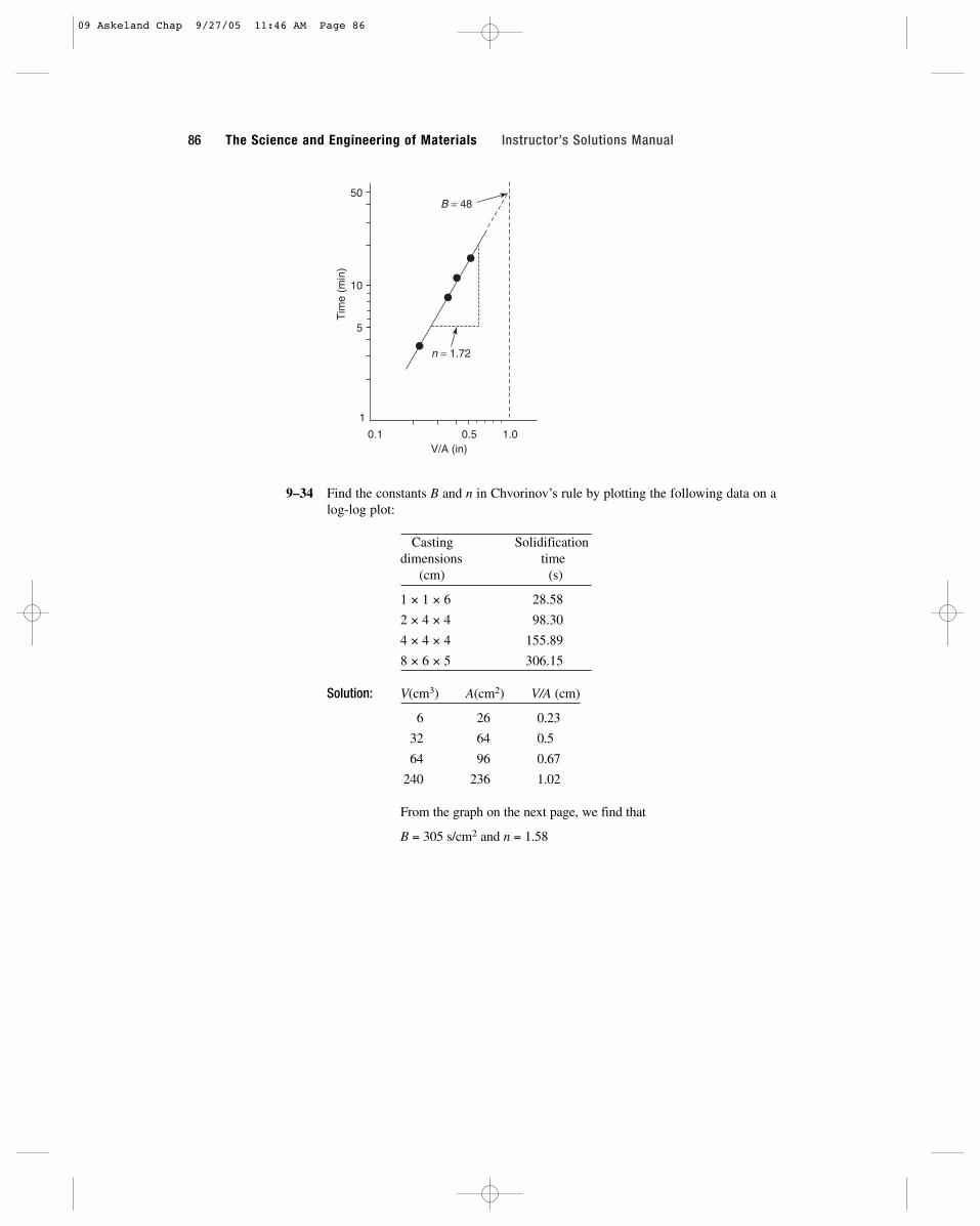
9–34 Find the constants B and n in Chvorinov’s rule by plotting the following data on alog-log plot:
Casting Solidificationdimensions time
(cm) (s)
1 × 1 × 6 28.58
2 × 4 × 4 98.30
4 × 4 × 4 155.89
8 × 6 × 5 306.15
Solution: V(cm3) A(cm2) V/A (cm)
6 26 0.23
32 64 0.5
64 96 0.67
240 236 1.02
From the graph on the next page, we find that
B = 305 s/cm2 and n = 1.58
Tim
e (m
in)
1
5
10
50
0.1 0.5 1.0V/A (in)
n = 1.72
B = 48
86 The Science and Engineering of Materials Instructor’s Solutions Manual
09 Askeland Chap 9/27/05 11:46 AM Page 86
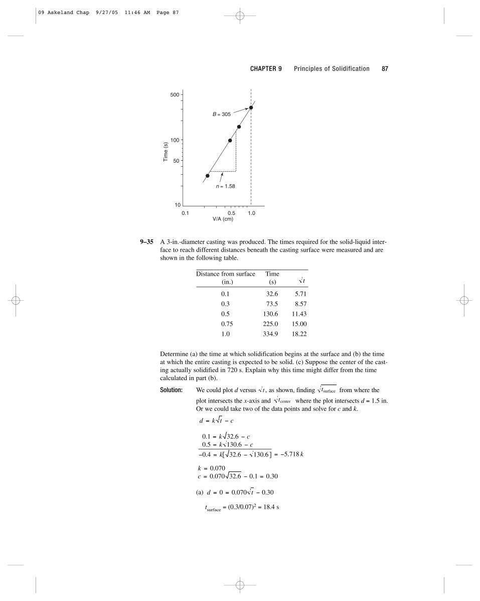
9–35 A 3-in.-diameter casting was produced. The times required for the solid-liquid inter-face to reach different distances beneath the casting surface were measured and areshown in the following table.
Distance from surface Time(in.) (s)
0.1 32.6 5.71
0.3 73.5 8.57
0.5 130.6 11.43
0.75 225.0 15.00
1.0 334.9 18.22
Determine (a) the time at which solidification begins at the surface and (b) the timeat which the entire casting is expected to be solid. (c) Suppose the center of the cast-ing actually solidified in 720 s. Explain why this time might differ from the timecalculated in part (b).
Solution: We could plot d versus as shown, finding from where the
plot intersects the x-axis and where the plot intersects d = 1.5 in.Or we could take two of the data points and solve for c and k.
(a)
tsurface = (0.3/0.07)2 = 18.4 s
d t= = −0 0 070 0 30. .
kc
== − =
0 0700 070 32 6 0 1 0 30
.
. . . .
0 1 32 60 5 130 6
0 4 32 6 130 6 5 718
. .
. .
. [ . . ] .
= −= −
− = − = −
k ck c
k k
d k t c= −
tcenter
tsurfacet ,
t
Tim
e (s
)
10
100
50
500
0.1 0.5 1.0V/A (cm)
n = 1.58
B = 305
CHAPTER 9 Principles of Solidification 87
09 Askeland Chap 9/27/05 11:46 AM Page 87
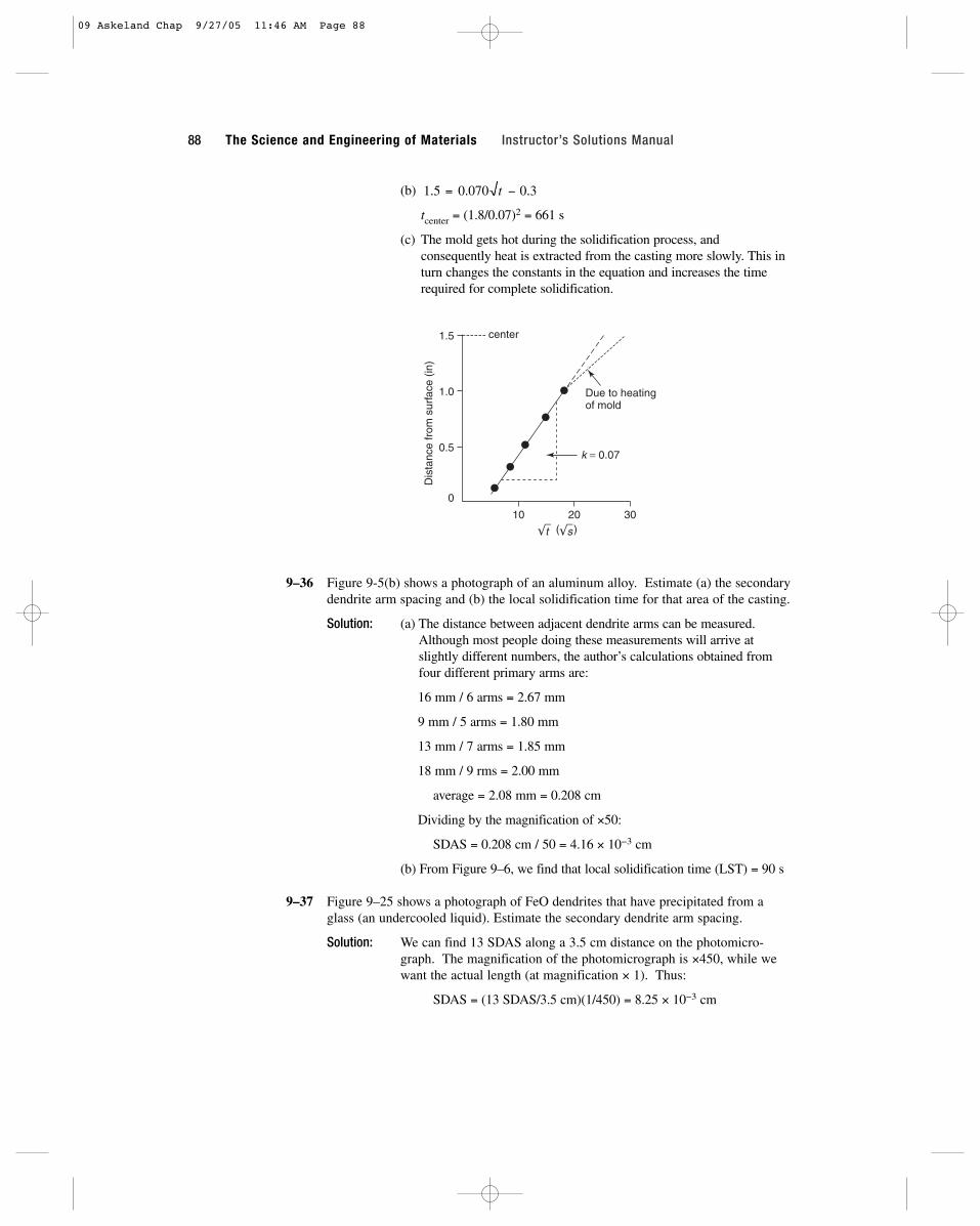
(b)
tcenter = (1.8/0.07)2 = 661 s
(c) The mold gets hot during the solidification process, and consequently heat is extracted from the casting more slowly. This inturn changes the constants in the equation and increases the timerequired for complete solidification.
9–36 Figure 9-5(b) shows a photograph of an aluminum alloy. Estimate (a) the secondarydendrite arm spacing and (b) the local solidification time for that area of the casting.
Solution: (a) The distance between adjacent dendrite arms can be measured.Although most people doing these measurements will arrive atslightly different numbers, the author’s calculations obtained fromfour different primary arms are:
16 mm / 6 arms = 2.67 mm
9 mm / 5 arms = 1.80 mm
13 mm / 7 arms = 1.85 mm
18 mm / 9 rms = 2.00 mm
average = 2.08 mm = 0.208 cm
Dividing by the magnification of ×50:
SDAS = 0.208 cm / 50 = 4.16 × 10⁻³ cm
(b) From Figure 9–6, we find that local solidification time (LST) = 90 s
9–37 Figure 9–25 shows a photograph of FeO dendrites that have precipitated from aglass (an undercooled liquid). Estimate the secondary dendrite arm spacing.
Solution: We can find 13 SDAS along a 3.5 cm distance on the photomicro-graph. The magnification of the photomicrograph is ×450, while wewant the actual length (at magnification × 1). Thus:
SDAS = (13 SDAS/3.5 cm)(1/450) = 8.25 × 10⁻³ cm
center
Dis
tanc
e fr
om s
urfa
ce (
in)
0.5
0
1.0
1.5
10 20 30
t s
k = 0.07
Due to heatingof mold
( )
1 5 0 070 0 3. . .= −t
88 The Science and Engineering of Materials Instructor’s Solutions Manual
09 Askeland Chap 9/27/05 11:46 AM Page 88

9–38 Find the constants k and m relating the secondary dendrite arm spacing to the localsolidification time by plotting the following data on a log-log plot:
Solidification Time SDAS(s) (cm)
156 0.0176
282 0.0216
606 0.0282
1356 0.0374
Solution: From the slope of the graph:
m = 34/100 = 0.34
We can then pick a point off the graph (say SDAS = 0.0225 cm whenLST = 300 s) and calculate “k”:
0.0225 = k(300)0.34 = 6.954k
k = 0.0032
9–39 Figure 9–26 shows dendrites in a titanium powder particle that has been rapidlysolidified. Assuming that the size of the titanium dendrites is related to solidificationtime by the same relationship as in aluminum, estimate the solidification time of thepowder particle.
Solution: The secondary dendrite arm spacing can be estimated from the pho-tomicrograph at several locations. The author’s calculations, derivedfrom measurements at three locations, are
11 mm / 8 arms = 1.375 mm
13 mm / 8 arms = 1.625 mm
13 mm / 8 arms = 1.625 mm
average = 1.540 mm
Dividing by the magnification of 2200:
SDAS = (1.540 mm)(0.1 cm/mm) / 2200 = 7 × 10⁻⁵ cm
The relationship between SDAS and solidification time for aluminum is:
SDAS = 8 × 10⁻⁴ t0.42 = 7 × 10⁻⁵
t = (0.0875)1/0.42 = 0.003 s
Time (s)
100 300 500 1000 3000
SD
AS
(cm
)
0.01
0.03
0.05
0.10
m = 0.34
CHAPTER 9 Principles of Solidification 89
09 Askeland Chap 9/27/05 11:46 AM Page 89

9–40 The secondary dendrite arm spacing in an electron-beam weld of copper is 9.5 × 10⁻⁴ cm. Estimate the solidification time of the weld.
Solution: From Figure 9–6, we can determine the equation relating SDAS and solidification time for copper:
n = 19/50 = 0.38 k = 4 × 10⁻³ cm
Then for the copper weld:
9.5 × 10−4 = 4 × 10⁻³(LST)0.38
(Note: LST is local solidification time)
0.2375 = (LST)0.38 or −1.438 = 0.38 ln LST
ln LST = −3.783 or LST = 0.023 s
9–45 A cooling curve is shown in Figure 9–27. Determine (a) the pouring temperature,(b) the solidification temperature, (c) the superheat, (d) the cooling rate just beforesolidification begins, (e) the total solidification time, (f) the local solidification time,and (g) the probable identity of the metal. (h) If the cooling curve was obtained atthe center of the casting sketched in the figure, determine the mold constant, assum-ing that n = 2.
Solution: (a) Tpour = 475oC (e) ts = 470 s
(b) Tsol = 320oC (f) LST = 470 − 170 = 300 s
(c) ∆Ts = 475 − 320 = 155oC (g) Cadmium (Cd)
(d) ∆T/∆t =475 − 320
= 1.0oC/s(h) ts = 470 = B[38.4/121.6]2
150 − 0 B = 4713 s/cm2
9–46 A cooling curve is shown in Figure 9–28. Determine (a) the pouring temperature,(b) the solidification temperature, (c) the superheat, (d) the cooling rate just beforesolidification begins, (e) the total solidification time, (f) the local solidification time,(g) the undercooling, and (h) the probable identity of the metal. (i) If the coolingcurve was obtained at the center of the casting sketched in the figure, determine themold constant, assuming n = 2.
Solution: (a) Tpour = 900oC (e) ts = 9.7 min
(b) Tsol = 420oC (f) LST = 9.7 − 1.6 = 8.1 min
(c) ∆Ts = 900 − 420 = 480oC (g) 420 − 360 = 60oC
(d) ∆T/∆t =900 − 400
= 312 oC/min(h) Zn
1.6 − 0
(i) ts = 9.7 = B[8/24]2 or B = 87.5 min/in.2
9–47 Figure 9–29 shows the cooling curves obtained from several locations within acylindrical aluminum casting. Determine the local solidification times and the SDASat each location, then plot the tensile strength versus distance from the casting sur-face. Would you recommend that the casting be designed so that a large or smallamount of material must be machined from the surface during finishing? Explain.
Solution: The local solidification times can be found from the cooling curvesand can be used to find the expected SDAS values from Figure 9–6.The SDAS values can then be used to find the tensile strength, usingFigure 9–7.
Surface: LST = 10 s ⇒ SDAS = 1.5 × 10⁻³ cm ⇒ TS = 47 ksi
90 The Science and Engineering of Materials Instructor’s Solutions Manual
09 Askeland Chap 9/27/05 11:46 AM Page 90

Midradius: LST = 100 s ⇒ SDAS = 5 × 10⁻³ cm ⇒ TS = 44 ksi
Center: LST = 500 s ⇒ SDAS = 10 × 10−3 cm ⇒ TS = 39.5 ksi
You prefer to machine as little material off the surface of the casting aspossible; the surface material has the finest structure and higheststrength; any excessive machining simply removes the “best” material.
9–48 Calculate the volume, diameter, and height of the cylindrical riser required to pre-vent shrinkage in a 4 in. × 10 in. × 20 in. casting if the H/D of the riser is 1.5.
Solution:(V/A)c =
(4)(10)(20) = 800/640 = 1.25
2(4)(10) + 2(4)(20) + 2(10)(20)
(V/A)r =(π/4)D2H
=(π/4)(3/2)D3
=3D/8
= 3D/16 ≥ 1.252(π/4)D2 + πDH (π/2)D2+(3π/2)D2 2
D ≥ 6.67 in. H ≥ 10 in. V ≥ 349 in.3
9–55 Calculate the volume, diameter, and height of the cylindrical riser required to pre-vent shrinkage in a 1 in. × 6 in. × 6 in. casting if the H/D of the riser is 1.0.
Solution: V = (1)(6)(6) = 36 in.3 A = 2(1)(6) + 2(1)(6) + 2(6)(6) = 96 in.2
(V/A)c = 36/96 = 0.375
(V/A)r =(π/4)D2H
=(π/4)D3
= D/6 ≥ 0.3752(π/4)D2 + πDH (3π/2)D2
D ≥ 2.25 in. H ≥ 2.25 in. V ≥ 8.95 in.3
9–56 Figure 9–30 shows a cylindrical riser attached to a casting. Compare the solidifica-tion times for each casting section and the riser and determine whether the riser willbe effective.
Solution:(V/A)thin =
(8)(6)(3) = 0.889
(3)(6) + 2(3)(8) + 2(6)(8)
(V/A)thick =(6)(6)(6)
= 1.13(6)(3) + 5(6)(6)− (π/4)(3)2
(V/A)riser =(π/4)(3)2(7)
= 0.68π(3)(7) + (π/4)(3)2
Note that the riser area in contact with the casting is not included ineither the riser or casting surface area; no heat is lost across this interface. In a like manner, the area of contact between the thick and thin
50
40
30Te
nsile
str
engt
h (k
si)
Surface Mid-radius Center
CHAPTER 9 Principles of Solidification 91
09 Askeland Chap 9/27/05 11:46 AM Page 91
portions of the casting are not included in the calculation of the castingarea.
The riser will not be effective; the thick section of the casting has thelargest V/A ratio and therefore requires the longest solidification time.Consequently the riser will be completely solid before the thick sectionis solidified; no liquid metal will be available to compensate for thesolidification shrinkage.
9–57 Figure 9–31 shows a cylindrical riser attached to a casting. Compare the solidifica-tion times for each casting section and the riser and determine whether the riser willbe effective.
Solution:(V/A)thick =
(4)(4)(4) = 0.73
5(4)(4) + 1(2)(4)
(V/A)thin =(2)(2)(4)
= 0.503(2)(4) + 2(2)(2)
(V/A)R =(π/4)(42)(8)
= 0.8π(4)(8) + 2(π/4)42
The area between the thick and thin sections of the casting are notincluded in calculating casting area; no heat is lost across this interface.
The riser will not be effective; the thin section has the smallest V/A ratioand therefore freezes first. Even though the riser has the longest solidifi-cation time, the thin section isolates the thick section from the riser, pre-venting liquid metal from feeding from the riser to the thick section.Shrinkage will occur in the thick section.
9–58 A 4-in.-diameter sphere of liquid copper is allowed to solidify, producing a sphericalshrinkage cavity in the center of the casting. Compare the volume and diameter ofthe shrinkage cavity in the copper casting to that obtained when a 4-in. sphere ofliquid iron is allowed to solidify.
Solution: Cu: 5.1% Fe: 3.4% rsphere = 4/2 = 2 in.
Cu: Vshrinkage = (4π/3)(2)3 (0.051) = 1.709 in.3
(4π/3)r3 = 1.709 in.3 or r = 0.742 in. dpore = 1.48 in.
Fe: Vshrinkage = (4π/3)(2)3 (0.034) = 1.139 in.3
(4π/3)r3 = 1.139 in.3 or r = 0.648 in.
dcavity = 1.30 in.
9–59 A 4-in. cube of a liquid metal is allowed to solidify. A spherical shrinkage cavitywith a diameter of 1.49 in. is observed in the solid casting. Determine the percentvolume change that occurs during solidification.
Solution: Vliquid = (4 in.)3 = 64 in.3
Vshrinkage = (4π/3)(1.49/2)3 = 1.732 in.3
Vsolid = 64 − 1.732 = 62.268 in.3
% volume change =64 − 62.268
× 100 = 2.7%64
92 The Science and Engineering of Materials Instructor’s Solutions Manual
09 Askeland Chap 9/27/05 11:46 AM Page 92
9–60 A 2 cm × 4 cm × 6 cm magnesium casting is produced. After cooling to room tem-perature, the casting is found to weigh 80 g. Determine (a) the volume of the shrink-age cavity at the center of the casting and (b) the percent shrinkage that must haveoccurred during solidification.
Solution: The density of the magnesium is 1.738 g/cm3
(a) Vinitial = (2)(4)(6) = 48 cm3
Vfinal = 80 g/1.738 g/cm3 = 46.03 cm3
(b) % shrinkage =48 − 46.03
× 100% = 4.1%48
9–61 A 2 in. × 8 in. × 10 in. iron casting is produced and, after cooling to room tempera-ture, is found to weigh 43.9 lb. Determine (a) the percent shrinkage that must haveoccurred during solidification and (b) the number of shrinkage pores in the casting ifall of the shrinkage occurs as pores with a diameter of 0.05 in.
Solution: The density of the iron is 7.87 g/cm3
(a) Vactual =(43.9 lb)(454 g)
= 2532.5 cm3
7.87 g/cm3
Vintended = (2)(8)(10) = 160 in.3 × (2.54 cm/in)3 = 2621.9 cm3
shrinkage =2621.9 − 2532.5
× 100% = 3.4%2621.9
(b) Vpores = 2621.9 − 2532.5 = 89.4 cm3
rpores = (0.05 in./2)(2.54 cm/in.) = 0.0635 cm
# pores =89.4 cm3
= 83,354 pores(4π/3)(0.0635 cm)3
9–65 Liquid magnesium is poured into a 2 cm × 2 cm × 24 cm mold and, as a result ofdirectional solidification, all of the solidification shrinkage occurs along the lengthof the casting. Determine the length of the casting immediately after solidification iscompleted.
Solution: Vinitial = (2)(2)(24) = 96 cm3
% contraction = 4 or 0.04 × 96 = 3.84 cm3
Vfinal = 96 − 3.84 = 92.16 cm3 = (2)(2)(L)
Length (L) = 23.04 cm
9–66 A liquid cast iron has a density of 7.65 g/cm3. Immediately after solidification, thedensity of the solid cast iron is found to be 7.71 g/cm3. Determine the percent vol-ume change that occurs during solidification. Does the cast iron expand or contractduring solidification?
Solution: 1/7.65 − 1/7.71× 100% =
0.1307 cm3 − 0.1297 cm3
× 100% = 0.77%1/7.65 0.1307 cm3
The casting contracts.
CHAPTER 9 Principles of Solidification 93
09 Askeland Chap 9/27/05 11:46 AM Page 93
9–67 From Figure 9–14, find the solubility of hydrogen in liquid aluminum just beforesolidification begins when the partial pressure of hydrogen is 1 atm. Determine thesolubility of hydrogen (in cm3/100 g Al) at the same temperature if the partial pres-sure were reduced to 0.01 atm.
Solution: 0.46 cm3 H2/100 g Aluminum
0.46/x =
9–68 The solubility of hydrogen in liquid aluminum at 715oC is found to be 1 cm3/100 gAl. If all of this hydrogen precipitated as gas bubbles during solidification andremained trapped in the casting, calculate the volume percent gas in the solidaluminum.
Solution: (1 cm3 H2/100 g Al)(2.699 g/cm3) = 0.02699 cm3 H2/cm3 Al = 2.699%
x = =0 46 0 01 0 046 1003. . . /cm g AL
1
0 01.
94 The Science and Engineering of Materials Instructor’s Solutions Manual
09 Askeland Chap 9/27/05 11:46 AM Page 94

95
10Solid Solutions and Phase Equilibrium
10–10 The unary phase diagram for SiO2 is shown in Figure 10–19. Locate the triple pointwhere solid, liquid, and vapor coexist and give the temperature and the type of solidpresent. What do the other “triple” points indicate?
Solution: (a) The solid-liquid-vapor triple point occurs at 1713�C; the solid phase pres-ent at this point is b-cristobalite.
(b) The other triple points describe the equilibrium between two solids and avapor phase.
10–22 Based on Hume-Rothery’s conditions, which of the following systems would beexpected to display unlimited solid solubility? Explain.
(a) Au–Ag (b) Al–Cu (c) Al–Au (d) U–W(e) Mo–Ta (f) Nb–W (g) Mg–Zn (h) Mg–Cd
Solution: (a)
(b)
(c)
(d)
¢ r � 0.7% No rW � 1.371 v � �4 FCC rU � 1.38 v � �4 Ortho
¢ r � 0.7% No rAu � 1.442 v � �1 FCC rAl � 1.432 v � �3 FCC
¢ r � 10.7% No rCu � 1.278 v � �1 FCC rAl � 1.432 v � �3 FCC
¢ r � 0.2% Yes rAg � 1.445 v � �1 FCC rAu � 1.442 v � �1 FCC
10 Askeland Chap 9/27/05 11:53 AM Page 95

96 The Science and Engineering of Materials Instructor’s Solutions Manual
(e)
(f)
(g)
(h)
The Au–Ag, Mo–Ta, and Mg–Cd systems have the required radius ratio, thesame crystal structures, and the same valences. Each of these might beexpected to display complete solid solubility. [The Au–Ag and Mo–Ta dohave isomorphous phase diagrams. In addition, the Mg–Cd alloys all solidifylike isomorphous alloys; however a number of solid-state phase transforma-tions complicate the diagram.]
10–23 Suppose 1 at% of the following elements is added to copper (forming a separatealloy with each element) without exceeding the solubility limit. Which one would beexpected to give the higher strength alloy? Is any of the alloying elements expectedto have unlimited solid solubility in copper?
(a) Au (b) Mn (c) Sr (d) Si (e) Co
Solution: For copper: rCu � 1.278 Å
(a) May be UnlimitedSolubility
(b) Different structure
(c) Highest Strength
(d) Different structure
(e) Different structure
The Cu–Sr alloy would be expected to be strongest (largest size difference).The Cu–Au alloy satisfies Hume-Rothery’s conditions and might be expectedto display complete solid solubility—in fact it freezes like an isomorphousseries of alloys, but a number of solid-state transformations occur at lowertemperatures.
10–24 Suppose 1 at% of the following elements is added to aluminum (forming a separatealloy with each element) without exceeding the solubility limit. Which one would beexpected to give the least reduction in electrical conductivity? Is any of the alloyelements expected to have unlimited solid solubility in aluminum?
(a) Li (b) Ba (c) Be (d) Cd (e) Ga
¢ r � �2.0%Co: r � 1.253
¢ r � �8.0%Si: r � 1.176
¢ r � �68.3%Sr: r � 2.151
¢ r � �12.4%Mn: r � 1.12
¢ r �rAu � rCu
rCu� �12.8%Au: r � 1.442
¢ r � 7.1% Yes rCd � 1.490 v � �2 HCP rMg � 1.604 v � �2 HCP
¢ r � 17% No rZn � 1.332 v � �2 HCP rMg � 1.604 v � �2 HCP
¢ r � 3.9% Yes rW � 1.371 v � �4 BCC rNb � 1.426 v � �4 BCC
¢ r � 4.7% No rTa � 1.43 v � �5 BCC rMo � 1.363 v � �4 BCC
10 Askeland Chap 9/27/05 11:53 AM Page 96
Solution: For aluminum: r � 1.432 Å (FCC structure with valence of 3)
(a)
(b)
(c)
(d)
(e)
The cadmium would be expected to give the smallest reduction in electricalconductivity, since the Cd atoms are most similar in size to the aluminumatoms.None are expected to have unlimited solid solubility, due either to differencein valence, atomic radius, or crystal structure.
10–25 Which of the following oxides is expected to have the largest solid solubility in Al2O3?
(a) Y2O3 (b) Cr2O3 (c) Fe2O3
Solution: The ionic radius of Al3� � 0.51 Å
(a)
(b)
(c)
We would expect Cr2O3 to have a high solubility in Al2O3; in fact, they arecompletely soluble in one another.
10–29 Determine the liquidus temperature, solidus temperature, and freezing range for thefollowing NiO–MgO ceramic compositions. [See Figure 10–9(b).]
(a) NiO–30 mol% MgO (b) NiO–45 mol% MgO(c) NiO–60 mol% MgO (d) NiO–85 mol% MgO
Solution: (a)
(b)
(c)
(d)
10–30 Determine the liquidus temperature, solidus temperature, and freezing range for thefollowing MgO–FeO ceramic compositions. (See Figure 10–21.)
(a) MgO–25 wt% FeO (b) MgO–45 wt% FeO(c) MgO–65 wt% FeO (d) MgO–80 wt% FeO
FR � 110°CTS � 2610°CTL � 2720°C
FR � 190°CTS � 2380°CTL � 2570°C
FR � 210°CTS � 2250°CTL � 2460°C
FR � 180°CTS � 2150°CTL � 2330°C
rFe3� � 0.64 ¢ r � 25.5%
rCr3� � 0.63 ¢ r � 23.5%
rY3� � 0.89 ¢ r �0.63 � 0.51
0.51� 100 � 74.5%
Ga: r � 1.218 ¢ r � 14.9% Orthorhombic valence � 3
Cd: r � 1.49 ¢ r � 4.1% HCP valence � 2
Be: r � 1.143 ¢ r � �20.2% HCP valence � 2
Ba: r � 2.176 ¢ r � �52.0% BCC valence � 2
Li: r � 1.519 ¢ r � 6.1% BCC valence � 1
CHAPTER 10 Solid Solutions and Phase Equilibrium 97
10 Askeland Chap 9/27/05 11:53 AM Page 97

98 The Science and Engineering of Materials Instructor’s Solutions Manual
Solution: (a)
(b)
(c)
(d)
10–31 Determine the phases present, the compositions of each phase, and the amountof each phase in mol% for the following NiO–MgO ceramics at 2400�C. [SeeFigure 10–9(b).]
(a) NiO–30 mol% MgO (b) NiO–45 mol% MgO(c) NiO–60 mol% MgO (d) NiO–85 mol% MgO
Solution: (a)
(b)
(c)
(d)
10–32 (a) Determine the phases present, the compositions of each phase, and the amountof each phase in wt% for the following MgO–FeO ceramics at 2000�C. (SeeFigure 10–21.)
(i) MgO–25 wt% FeO (ii) MgO–45 wt% FeO(iii) MgO–60 wt% FeO (iv) MgO–80 wt% FeO
Solution: (i)
(ii)
(iii)
(iv) 100% LS: 80% MgO
%L �60 � 39
65 � 39� 100% � 80.8%L: 65% MgO
%S �65 � 60
65 � 39� 100% � 19.2%S: 39% FeO
%L �45 � 39
65 � 39� 100% � 23.1%L: 65% FeO
%S �65 � 45
65 � 39� 100% � 76.9%S: 39% FeO
100% SS: 25% FeO
100% SS: 85% MgO
%L �60 � 38
62 � 38� 100% � 91.7%S: 62% MgO
%L �62 � 60
62 � 38� 100% � 8.3%L: 38% MgO
%L �45 � 38
62 � 38� 100% � 29.2%S: 62% MgO
%L �62 � 45
62 � 38� 100% � 70.8%L: 38% MgO
100% LL: NiO–30 mol% MgO
FR � 270°CTS � 1480°CTL � 1750°C
FR � 390°CTS � 1610°CTL � 2000°C
FR � 440°CTS � 1900°CTL � 2340°C
FR � 370°CTS � 2230°CTL � 2600°C
% S
% L
% S
% L
% L
% L
% L
% L
10 Askeland Chap 9/27/05 11:53 AM Page 98

(b) Consider an alloy of 65 wt% Cu and 35 wt% Al. Calculate the composition ofthe alloy in at%.
Solution: (b)
10–33 Consider a ceramic composed of 30 mol% MgO and 70 mol% FeO. Calculate thecomposition of the ceramic in wt%.
Solution:
10–34 A NiO–20 mol% MgO ceramic is heated to 2200�C. Determine (a) the compositionof the solid and liquid phases in both mol% and wt% and (b) the amount of eachphase in both mol% and wt%. (c) Assuming that the density of the solid is 6.32g/cm3 and that of the liquid is 7.14 g/cm3, determine the amount of each phase invol% (see Figure 10–9(b)).
Solution:
(a)
(b)
The original composition, in wt% MgO, is:
(c)
Vol% S � 21.9%
Vol% L �80.1�7.14
180.1�7.142� 119.9�6.322� 100% � 78.1%
wt% L �24.85 � 11.9
24.85 � 8.69� 100% � 80.1% wt% S � 19.9%
1202140.3122
1202140.3122� 1802174.712� 100% � 11.9%
mol% L �38 � 20
38 � 15� 100% � 78.26% mol% S � 21.74%
wt% MgO �1382140.3122
1382140.3122� 1622174.712� 100% � 24.85%
S: 38 mol% MgO
wt% MgO �1152140.3122
1152140.3122� 1852174.712� 100% � 8.69%
L: 15 mol% MgO
MWNiO � 58.71 � 16 � 74.71 g/mol
MWMgO � 24.312 � 16 � 40.312 g/mol
wt% FeO �1702171.8472
1302140.3122� 1702171.8472� 100% � 80.6%
wt% MgO �1302140.3122
1302140.3122� 1702171.8472� 100% � 19.4%
MWFeO � 55.847 � 16 � 71.847 g/mol
MWMgO � 24.312 � 16 � 40.312 g/mol
At% Al �35�26.981
165�63.542� 135�26.9812� 100% � 55.9%
At% Cu �65�63.54
165�63.542� 135�26.9812� 100% � 44.1%
CHAPTER 10 Solid Solutions and Phase Equilibrium 99
at
vol
vol
at
10 Askeland Chap 9/27/05 11:53 AM Page 99
100 The Science and Engineering of Materials Instructor’s Solutions Manual
10–35 A Nb–60 wt% W alloy is heated to 2800�C. Determine (a) the composition of thesolid and liquid phases in both wt% and at% and (b) the amount of each phase inboth wt% and at%. (c) Assuming that the density of the solid is 16.05 g/cm3 andthat of the liquid is 13.91 g/cm3, determine the amount of each phase in vol%.(See Figure 10–22.)
Solution: (a)
(b)
The original composition, in wt% MgO, is:
(c)
10–36 How many grams of nickel must be added to 500 grams of copper to produce analloy that has a liquidus temperature of 1350�C? What is the ratio of the number ofnickel atoms to copper atoms in this alloy?
Solution: We need 60 wt% Ni to obtain the correct liquidus temperature.
10–37 How many grams of nickel must be added to 500 grams of copper to produce analloy that contains 50 wt% a at 1300�C?
Solution: At 1300�C, the composition of the two phases in equilibrium are
The alloy required to give 50% a is then
x � 46
58 � 46� 100 � 50% a or x � 52 wt% Ni
L: 46 wt% Ni and a: 58 wt% Ni
Ni atoms
Cu atoms�
1750 g21NA2�58.71 g/mol
1500 g21NA2�63.54 g/mol� 1.62
%Ni � 60 �x
x � 500 g� 100% or x � 750 g Ni
Vol% a � 48.8%
Vol% L �47.6�13.91
147.6�13.912� 152.4�16.052� 100% � 51.2%
at% L �54.1 � 43.1
54.1 � 32.7� 100% � 51.4% wt% a � 48.6%
60�183.85
160�183.852� 140�92.912� 100% � 43.1%
wt% L �70 � 60
70 � 49� 100% � 47.6% wt% a � 52.4%
at% W �170�183.852
170�183.852� 130�92.912� 100% � 54.1%
a: 70 wt% W
at% W �49�183.85
149�183.852� 151�92.912� 100% � 32.7%
L: 49 wt% W
vol
vol
10 Askeland Chap 9/27/05 11:53 AM Page 100
The number of grams of Ni must be:
10–38 How many grams of MgO must be added to 1 kg of NiO to produce a ceramic thathas a solidus temperature of 2200�C?
Solution:
38 mol% MgO is needed to obtain the correct solidus temperature.
The number of grams required is:
10–39 How many grams of MgO must be added to 1 kg of NiO to produce a ceramic thatcontains 25 mol% solid at 2400�C?
Solution:
The number of grams of MgO is then:
10–40 We would like to produce a solid MgO–FeO ceramic that contains equal molpercentages of MgO and FeO at 1200�C. Determine the wt% FeO in the ceramic.(See Figure 10–21.)
Solution: Only solid is present at 1200�C.
10–41 We would like to produce a MgO–FeO ceramic that is 30 wt% solid at 2000�C.Determine the original composition of the ceramic in wt%. (See Figure 10–21.)
Solution:
30 wt% �65 � x
65 � 38� 100% or x � 56.9 wt% FeO
S: 38 wt% FeOL: 65 wt% FeO
50 mol% FeO: 1502171.8472
1502140.3122� 1502171.8472� 64.1 wt% FeO
MWFeO � 71.847 g/mol
MWMgO � 40.312 g/mol
x
x � 1000� 100% � 29.77% or x � 424 g MgO
wt% MgO �1442140.3122
1442140.3122� 1562174.712� 100% � 29.77%
x � 38
62 � 38� 100% � 25%S or x � 44 mol% MgO
S: 62 mol% MgO MWNiO � 74.71 g/mol
L: 38 mol% MgO MWMgO � 40.312 g/mol
x
x � 1000� 100% � 24.9% or x � 332 g of MgO
wt% MgO �1382140.3122
1382140.3122� 1622174.712� 100% � 24.9%
MWMgO � 40.312 g/mol MWNiO � 74.71 g/mol
x
x � 500� 100% � 52 or x � 541.7 g Ni
CHAPTER 10 Solid Solutions and Phase Equilibrium 101
10 Askeland Chap 9/27/05 11:53 AM Page 101

102 The Science and Engineering of Materials Instructor’s Solutions Manual
10–42 A Nb–W alloy held at 2800�C is partly liquid and partly solid. (a) If possible,determine the composition of each phase in the alloy; and (b) if possible,determine the amount of each phase in the alloy. (See Figure 10–22.)
Solution: (a)
(b) Not possible unless we know the original composition of the alloy.
10–43 A Nb–W alloy contains 55% a at 2600�C. Determine (a) the composition of eachphase; and (b) the original composition of the alloy. (See Figure 10–22.)
Solution: (a)
(b)
10–44 Suppose a 1200-lb bath of a Nb–40 wt% W alloy is held at 2800�C. How manypounds of tungsten can be added to the bath before any solid forms? How manypounds of tungsten must be added to cause the entire bath to be solid? (SeeFigure 10–22.)
Solution: Solid starts to form at 2800�C when 49 wt% W is in the alloy. In 1200 lbof the original Nb–40% W alloy, there are (0.4)(1200) � 480 lb W and720 lb Nb. The total amount of tungsten that must be in the final alloy is:
To be completely solid at 2800�C, the alloy must contain 70 wt% W. Thetotal amount of tungsten required in the final alloy is:
10–45 A fiber-reinforced composite material is produced, in which tungsten fibers areembedded in a Nb matrix. The composite is composed of 70 vol% tungsten. (a)Calculate the wt% of tungsten fibers in the composite. (b) Suppose the composite isheated to 2600�C and held for several years. What happens to the fibers? Explain.(See Figure 10–22.)
Solution: (a)
(b) The fibers will dissolve. Since the W and Nb are completely soluble in oneanother, and the temperature is high enough for rapid diffusion, a singlesolid solution will eventually be produced.
10–46 Suppose a crucible made of pure nickel is used to contain 500 g of liquid copper at1150�C. Describe what happens to the system as it is held at this temperature forseveral hours. Explain.
wt% �170 cm32119.254 g/cm32
1702119.2542� 130218.572� 83.98 wt% W
or 1680 � 480 � 1200 additional pounds of W must be added
0.70 �x
x � 720 or x � 1680 lb W total
or 692 � 480 � 212 additional pounds of W must be added
0.49 �x
x � 720 or x � 692 lb W total
0.55 �x � 22
42 � 22 or x � 33 wt% W
a: 42 wt% WL: 22 wt% W
a: 70 wt% WL: 49 wt% W
10 Askeland Chap 9/27/05 11:53 AM Page 102
Solution: Cu dissolves Ni until the Cu contains enough Ni that it solidifies com-pletely. When 10% Ni is dissolved, freezing begins:
When 18% Ni dissolved, the bath is completely solid:
10–49 Equal moles of MgO and FeO are combined and melted. Determine (a) the liquidustemperature, the solidus temperature, and the freezing range of the ceramic and (b)determine the phase(s) present, their composition(s), and their amount(s) at 1800�C.(See Figure 10–21.)
Solution:
(a)
(b)
10–50 Suppose 75 cm3 of Nb and 45 cm3 of W are combined and melted. Determine (a)the liquidus temperature, the solidus temperature, and the freezing range of the alloyand (b) determine the phase(s) present, their composition(s), and their amount(s) at2800�C. (See Figure 10–22.)
Solution:
(a)
(b)
10–51 A NiO–60 mol% MgO ceramic is allowed to solidify. Determine (a) the composi-tion of the first solid to form and (b) the composition of the last liquid to solidifyunder equilibrium conditions.
Solution: (a) (b)
10–52 A Nb–35% W alloy is allowed to solidify. Determine (a) the composition of the firstsolid to form and (b) the composition of the last liquid to solidify under equilibriumconditions. (See Figure 10–22.)
Solution: (a) (b) Last L: 18% W1st a: 55% W
Last L: 35% MgO1st a: 80% MgO
a: 70%W %a � 40%
L: 49%W %L �70 � 57.4
70 � 49� 60%
TLiq � 2900°C TSol � 2690°C FR � 210°C
wt% W �145 cm32119.254 g/cm32
1452119.2542� 175218.572� 100 � 57.4 wt% W
%L �64.1 � 50
75 � 50� 100% � 56.4% %S � 43.6%
L: 75% FeO S: 50% FeO
TLiq � 2000°C Ts � 1620°C FR � 380°C
wt% FeO �11 mol FeO2171.847 g/mol2
11 mol FeO2171.8472� 11 mol MgO2140.3122� 64.1%
MWFeO � 71.847 g/molMWMgO � 40.312 g/mol
0.18 �x
x � 500 or x � 109.8 g Ni
0.10 �x
x � 500 or x � 55.5 g Ni
CHAPTER 10 Solid Solutions and Phase Equilibrium 103
% S
W %
%
%
W
10 Askeland Chap 9/27/05 11:53 AM Page 103
104 The Science and Engineering of Materials Instructor’s Solutions Manual
10–53 For equilibrium conditions and a MgO–65 wt% FeO ceramic, determine (a) the liq-uidus temperature, (b) the solidus temperature, (c) the freezing range, (d) the com-position of the first solid to form during solidification, (e) the composition of thelast liquid to solidify, (f) the phase(s) present, the composition of the phase(s), andthe amount of the phase(s) at 1800�C, and (g) the phase(s) present, the compositionof the phase(s), and the amount of the phase(s) at 1600�C. (See Figure 10–21.)
Solution: (a)
(b)
(c)
(d)
(e)
(f)
(g)
10–54 Figure 10–23 shows the cooling curve for a NiO–MgO ceramic. Determine (a) theliquidus temperature, (b) the solidus temperature, (c) the freezing range, (d) thepouring temperature, (e) the superheat, (f ) the local solidification time, (g) the totalsolidification time, and (h) the composition of the ceramic.
Solution: (a)
(b)
(c)
(d)
(e)
(f)
(g)
(h)
10–55 For equilibrium conditions and a Nb–80 wt% W alloy, determine (a) the liquidustemperature, (b) the solidus temperature, (c) the freezing range, (d) the compositionof the first solid to form during solidification, (e) the composition of the last liquidto solidify, (f) the phase(s) present, the composition of the phase(s), and the amountof the phase(s) at 3000�C, and (g) the phase(s) present, the composition of thephase(s), and the amount of the phase(s) at 2800�C. (see Figure 10–22.)
Solution: (a)
(b)
(c) Freezing range � 3100 � 2920 � 180°C
Solidus � 2920°C
Liquidus � 3100°C
80% MgO
Total solidification time � 27 min
Local solidification time � 27 � 5 � 22 min
Superheat � 2775 � 2690 � 85°C
Pouring temperature � 2775°C
Freezing range � 2690 � 2570 � 120°C
Solidus � 2570°C
Liquidus � 2690°C
a: 65% FeO 100% a
a: 51% FeO %a � 42%
L: 75% FeO %L �65 � 51
75 � 51� 100% � 58%
Last liquid: 88% FeO
First solid: 40% FeO
Freezing range � 2000 � 1605 � 395°C
Solidus � 1605°C
Liquidus � 2000°C
%
%
10 Askeland Chap 9/27/05 11:53 AM Page 104

(d)
(e)
(f)
(g)
10–56 Figure 10–24 shows the cooling curve for a Nb–W alloy. Determine (a) the liquidustemperature, (b) the solidus temperature, (c) the freezing range, (d) the pouringtemperature, (e) the superheat, (f ) the local solidification time, (g) the totalsolidification time, and (h) the composition of the alloy.
Solution: (a)
(b)
(c)
(d)
(e)
(f)
(g)
(h) Nb–60 wt% W
10–57 Cooling curves are shown in Figure 10–25 for several Mo–V alloys. Based on thesecurves, construct the Mo–V phase diagram.
Solution: TLiquidus TSolidus
0% V 2630°C20% V 2500°C 2320°C40% V 2360°C 2160°C60% V 2220°C 2070°C80% V 2100°C 1970°C
100% V 1930°C
2000
2200
2400
2600
Mo 20 40 60 80 V
L
a
a + L
%V
Tem
pera
ture
(°C
)
Local solidification time � 340 � 40 � 300 s
Superheat � 2990 � 2900 � 90°C
Pouring temperature � 2990°C
Freezing range � 2900 � 2710 � 190°C
Solidus � 2710°C
Liquidus � 2900°C
a: 80% W 100% a
a: 85% W %a � 66.7%
L: 70% W %L �85 � 80
85 � 70� 100% � 33.3%
Last liquid: 64% W
First solid: 90% W
CHAPTER 10 Solid Solutions and Phase Equilibrium 105
Total solidificaton time � 340 sec
%
%
10 Askeland Chap 9/27/05 11:53 AM Page 105
106 The Science and Engineering of Materials Instructor’s Solutions Manual
10–59 For the nonequilibrium conditions shown for the MgO–65 wt% FeO ceramic,determine (a) the liquidus temperature, (b) the nonequilibrium solidus temperature,(c) the freezing range, (d) the composition of the first solid to form during solidifi-cation, (e) the composition of the last liquid to solidify, (f) the phase(s) present, thecomposition of the phase(s), and the amount of the phase(s) at 1800�C, and (g) thephase(s) present, the composition of the phase(s), and the amount of the phase(s) at1600�C. (See Figure 10–20.)
Solution: (a)
(b)
(c)
(d)
(e)
(f)
(g)
10–60 For the nonequilibrium conditions shown for the Nb–80 wt% W alloy, determine (a)the liquidus temperature, (b) the nonequilibrium solidus temperature, (c) the freez-ing range, (d) the composition of the first solid to form during solidification, (e) thecomposition of the last liquid to solidify, (f) the phase(s) present, the composition ofthe phase(s), and the amount of the phase(s) at 3000�C, and (g) the phase(s) present,the composition of the phase(s), and the amount of the phase(s) at 2800�C. (SeeFigure 10–21.)
Solution: (a)
(b)
(c)
(d)
(e)
(f)
(g)
a: 83% W %a � 90.9%
L: 50% W %L �83 � 80
83 � 50� 100% � 9.1%
a: 88% W %a � 55.6%
L: 70% W %L �88 � 80
88 � 70� 100% � 44.4%
Last liquid: 40% W
First solid: 90% W
Freezing range � 3100 � 2720 � 380°C
Solidus � 2720°C
Liquidus � 3100°C
S: 55% FeO %S � 69.7%
L: 88% FeO %L �65 � 55
88 � 55� 100% � 30.3%
S: 46% FeO %S � 34.5%
L: 75% FeO %L �65 � 46
75 � 46� 100% � 65.5%
Last liquid: 92% FeO
First solid: 40% FeO
Freezing range � 2000 � 1450 � 550°C
Solidus � 1450°C
Liquidus � 2000°C
% S
% S
% L
% L
%
%
%
%
10 Askeland Chap 9/27/05 11:53 AM Page 106
107
11Dispersion Strengthening andEutectic Phase Diagrams
11–7 A hypothetical phase diagram is shown in Figure 11–25. (a) Are any intermetalliccompounds present? If so, identify them and determine whether they are stoichio-metric or nonstoichiometric. (b) Identify the solid solutions present in the system. Iseither material A or B allotropic? Explain. (c) Identify the three-phase reactions bywriting down the temperature, the reaction in equation form, the composition ofeach phase in the reaction, and the name of the reaction.
Solution: (a) u � non-stoichiometric intermetallic compound.
(b) a, h, g, and b; material B is allotropic, existing in three different forms atdifferent temperatures
(c)
11–8 The Cu–Zn phase diagram is shown in Figure 11–26. (a) Are any intermetallic com-pounds present? If so, identify them and determine whether they are stoichiometricor nonstoichiometric. (b) Identify the solid solutions present in the system. (c)Identify the three-phase reactions by writing down the temperature, the reaction inequation form, and the name of the reaction.
u: 40% B h: 95% B 300°C: b S u � h; eutectoid; b: 90% B
b: 80% B u: 37% B 600°C: a � b S u; peritectoid; a: 5% B
a: 5% B b: 90% B 680°C: L S a � b; eutectic; L: 60% B
L 2: 50% B a: 5% B 900°C: L1 S L2 � a; monotectic; L1: 28% B
g: 97% B b: 90% B 1100°C: g � L S b; peritectic; L: 82% B
11 Askeland Chap 9/27/05 1:48 PM Page 107

108 The Science and Engineering of Materials Instructor’s Solutions Manual
Solution: (a) b, b�, g, d, e: all nonstoichiometric.
(b) a, u
(c)
11–9 The Al–Li phase diagram is shown in Figure 11–27. (a) Are any intermetallic com-pounds present? If so, identify them and determine whether they are stoichiometricor nonstoichiometric. Determine the formula for each compound. (b) Identify thethree-phase reactions by writing down the temperature, the reaction in equationform, the composition of each phase in the reaction, and the name of the reaction.
Solution: (a) b is non-stoichiometric @ 21 wt% Li:
g, is stoichiometric @ 34 wt% Li:
(b)
11–11 An intermetallic compound is found for 10 wt% Si in the Cu–Si phase diagram.Determine the formula for the compound.
Solution:
11–12 Consider a Pb–15% Sn alloy. During solidification, determine (a) the compositionof the first solid to form, (b) the liquidus temperature, solidus temperature, solvustemperature, and freezing range of the alloy, (c) the amounts and compositions ofeach phase at 260°C, (d) the amounts and compositions of each phase at 183°C, and(e) the amounts and compositions of each phase at 25°C.
Solution: (a) 8% Sn
(b) liquidus � 290°C, solidus � 240°C,solvus � 170°C, freezing range � 50°C
at% Si �10 g�28.08 g/mol
10�28.08 � 90�63.54� 0.20 or SiCu4
g: 34% Li a 1Li2: 99% Li170°C: L S g � a 1Li2 eutectic L: 98% Li
L: 47% Li g: 34% Li510°C: b � L S g peritectic b: 25% Li
a: 4% Li b: 20.4% Li600°C: L S a � b eutectic L: 9.9% Li
at% Li �34 g�6.94 g/mol
34�6.94 � 66�26.981� 100% � 66.7% Li ∴ AlLi2
at% Li �21 g�6.94 g/mol
21�6.94 � 79�26.981� 100% � 50 at% Li ∴ AlLi
250°C: b¿S a � g; eutectoid
420°C: e � L S u; peritectic
550°C: d S g � e; eutectoid
600°C: d � L S e; peritectic
700°C: g � L S d; peritectic
830°C: b � L S g; peritectic
900°C: a � L S b; peritecticperitectic
peritectic
peritectic
peritectic
eutectoid
peritectic
eutectoid
11 Askeland Chap 9/27/05 1:48 PM Page 108

(c) L: 30% Sn a: 12% Sn;
(d) a: 15% Sn 100% a
(e) a: 2% Pb b: 100% Sn
11–13 Consider an Al–12% Mg alloy (Figure 11–28). During solidification, determine(a) the composition of the first solid to form, (b) the liquidus temperature, solidustemperature, solvus temperature, and freezing range of the alloy, (c) the amountsand compositions of each phase at 525°C, (d) the amounts and compositions of eachphase at 450°C, and (e) the amounts and compositions of each phase at 25°C.
Solution: (a) 2.5% Mg
(b) liquidus � 600°C, solidus � 470°C,solvus � 400°C, freezing range � 130°C
(c) L: 26% Mg a: 7% Mg;
(d) a: 12% Mg 100% a
(e)
11–14 Consider a Pb–35% Sn alloy. Determine (a) if the alloy is hypoeutectic or hypereu-tectic, (b) the composition of the first solid to form during solidification, (c) theamounts and compositions of each phase at 184°C, (d) the amounts and composi-tions of each phase at 182°C, (e) the amounts and compositions of each microcon-stituent at 182°C, and (f) the amounts and compositions of each phase at 25°C.
Solution: (a) hypoeutectic (b) 14% Sn
(c)
(d)
(e) primary a: 19% Sn % primary a � 63%eutectic: 61.9% Sn % eutectic � 37%
(f)
%a �100 � 35
100 � 2� 100% � 66% %b � 34%
a: 2% Sn b: 100% Sn
%a �97.5 � 35
97.5 � 19� 100% � 80% %b � 20%
a: 19% Sn b: 97.5% Sn
%a �61.9 � 35
61.9 � 19� 100% � 63% %L � 37%
a: 19% Sn L: 61.9% Sn
%a �34 � 12
34 � 1� 100% � 67% %b � 33%
a: 1% Mg b: 34% Mg
%a �26 � 12
26 � 7� 100% � 74% %L � 26%
%a �100 � 15
100 � 2� 100 � 87% %b � 13%
%L �15 � 12
30 � 12� 100% � 17% %a � 83%
CHAPTER 11 Dispersion Strengthening and Eutectic Phase Diagrams 109
%
%
%
%
%
%
%
%
%
%
%
%
%
%
11 Askeland Chap 9/27/05 1:48 PM Page 109
110 The Science and Engineering of Materials Instructor’s Solutions Manual
11–15 Consider a Pb–70% Sn alloy. Determine (a) if the alloy is hypoeutectic or hypereu-tectic, (b) the composition of the first solid to form during solidification, (c) theamounts and compositions of each phase at 184°C, (d) the amounts and composi-tions of each phase at 182°C, (e) the amounts and compositions of each microcon-stituent at 182°C, and (f) the amounts and compositions of each phase at 25°C.
Solution: (a) hypereutectic (b) 98% Sn
(c)
(d)
(e) primary b: 97.5% Sn % primary b� 22.8%eutectic: 61.9% Sn % eutectic � 77.2%
(f)
11–16 Calculate the total % b and the % eutectic microconstituent at room temperature forthe following lead-tin alloys: 10% Sn, 20% Sn, 50% Sn, 60% Sn, 80% Sn, and 95%Sn. Using Figure 11–18, plot the strength of the alloys versus the % b and the % eutectic and explain your graphs.
Solution: % b % eutectic
10% Sn 0%
20% Sn
50% Sn
60% Sn
80% Sn
95% Sn 97.5 � 95
97.5 � 61.9� 7.0%
95 � 2
99 � 2� 95.9%
97.5 � 80
97.5 � 61.9� 49.2%
80 � 2
99 � 2� 80.4%
60 � 19
61.9 � 19� 95.6%
60 � 2
99 � 2� 59.8%
50 � 19
61.9 � 19� 72.3%
50 � 2
99 � 2� 49.5%
20 � 19
61.9 � 19� 2.3%
20 � 2
99 � 2� 18.6%
10 � 2
99 � 2� 8.2%
%a �100 � 70
100 � 2� 100% � 30% %b � 70%
a: 2% Sn b: 100% Sn
%a �97.5 � 70
97.5 � 19� 100% � 35% %b � 65%
a: 19% Sn b: 97.5% Sn
%b �70 � 61.9
97.5 � 61.9� 100% � 22.8% %L � 77.2%
b: 97.5% Sn L: 61.9% Sn
% L � 77.2%
% b � 65%
%
%
% % b � 70%
11 Askeland Chap 9/27/05 1:48 PM Page 110

CHAPTER 11 Dispersion Strengthening and Eutectic Phase Diagrams 111
11–17 Consider an Al–4% Si alloy. (See Figure 11–19.) Determine (a) if the alloy ishypoeutectic or hypereutectic, (b) the composition of the first solid to form duringsolidification, (c) the amounts and compositions of each phase at 578°C, (d) theamounts and compositions of each phase at 576°C, the amounts and compositionsof each microconstituent at 576°C, and (e) the amounts and compositions of eachphase at 25°C.
Solution: (a) hypoeutectic
(b) 1% Si
(c)
(d)
primary a: 1.65% Si % primary a� 78.5%eutectic: 12.6% Si % eutectic � 21.5%
(e)
11–118 Consider a Al–25% Si alloy. (See Figure 11–19.) Determine (a) if the alloy ishypoeutectic or hypereutectic, (b) the composition of the first solid to form duringsolidification, (c) the amounts and compositions of each phase at 578°C, (d) theamounts and compositions of each phase at 576°C, (e) the amounts and composi-tions of each microconstituent at 576°C, and (f) the amounts and compositions ofeach phase at 25°C.
Solution: (a) hypereutectic
(b) 100% Si
a: 0% Si b: 100% Si %a �100 � 4
100 � 0� 96% %b � 4%
%a �99.83 � 4
99.83 � 1.65� 97.6% %b � 2.4%
a: 1.65% Si b: 99.83% Si
%a �12.6 � 4
12.6 � 1.65� 78.5% %L � 21.5%
a: 1.65% Si L: 12.6% Si
20 40 60 80 1004000
5000
6000
7000
8000
% β
Tens
ile s
tren
gth
(psi
)
20 40 60 80
5000
6000
7000
8000
% eutectic
Hypo-
Hyper-
Tens
ile s
tren
gth
(psi
)
% L � 21.5%
% b � 2.4%
% b � 4%% a
%
%
11 Askeland Chap 9/27/05 1:48 PM Page 111
112 The Science and Engineering of Materials Instructor’s Solutions Manual
(c)
(d)
(e) primary b: 99.83% Si % primary b� 14.2%eutectic: 12.6% Si % eutectic � 85.8%
(f)
11–19 A Pb–Sn alloy contains 45% a and 55% b at 100°C. Determine the composition ofthe alloy. Is the alloy hypoeutectic or hypereutectic?
Solution:
11–20 An Al–Si alloy contains 85% a and 15% b at 500°C. Determine the composition ofthe alloy. Is the alloy hypoeutectic or hypereutectic?
Solution:
11–21 A Pb–Sn alloy contains 23% primary a and 77% eutectic microconstituent.Determine the composition of the alloy.
Solution:
11–22 An Al–Si alloy contains 15% primary b and 85% eutectic microconstituent.Determine the composition of the alloy.
Solution:
11–23 Observation of a microstructure shows that there is 28% eutectic and 72% primary bin an Al–Li alloy (Figure 11–27). (a) Determine the composition of the alloy andwhether it is hypoeutectic or hypereutectic. (b) How much a and b are in the eutec-tic microconstituent?
Solution: (a)
(b) %aEut �20.4 � 9.9
20.4 � 4� 100% � 64% and %bEut � 36%
28 �20.4 � x
20.4 � 9.9� 100 or x � 17.46% Li Hypereutectic
%eutectic � 85 �100 � x
100 � 12.6� 100 or x � 25.71% Si
%primary a � 23 �61.9 � x
61.9 � 19� 100 or x � 52% Sn
%a � 85 �100 � x
100 � 1� 100 or x � 15.85% Si Hypereutectic
%a � 45 �98.0 � x
98.0 � 5� 100 or x � 56.15% Sn Hypoeutectic
a: 0% Si b: 100% Si %a �100 � 25
100 � 0� 75% %b � 25%
%a �99.83 � 25
99.83 � 1.65� 76.2% %b � 23.8%
a: 1.65% Si b: 99.83% Si
%L �99.83 � 25
99.83 � 12.6� 85.8% %b � 14.2%
b: 99.83% Si L: 12.6% Si
% b � 14.2%
% b � 23.8%
% b � 25%
%
%
% a
% a
% a
%
%
%%
11 Askeland Chap 9/27/05 1:48 PM Page 112
11–24 Write the eutectic reaction that occurs, including the compositions of the threephases in equilibrium, and calculate the amount of a and b in the eutectic microcon-stituent in the Mg–Al system, (Figure 11–28).
Solution:
11–25 Calculate the total amount of a and b and the amount of each microconstituent in aPb–50% Sn alloy at 182°C. What fraction of the total a in the alloy is contained inthe eutectic microconstituent?
Solution:
11–26 Figure 11–29 shows a cooling curve for a Pb–Sn alloy. Determine (a) the pouringtemperature, (b) the superheat, (c) the liquidus temperature, (d) the eutectic tempera-ture, (e) the freezing range, (f) the local solidification time, (g) the total solidifica-tion time, and (h) the composition of the alloy.
Solution: (a)
(b)
(c)
(d)
(e)
(f)
(g)
(h) approximately 32% Sn
11–27 Figure 11–30 shows a cooling curve for an Al–Si alloy. Determine (a) the pouringtemperature, (b) the superheat, (c) the liquidus temperature, (d) the eutectic tempera-ture, (e) the freezing range, (f) the local solidification time, (g) the total solidifica-tion time, and (h) the composition of the alloy.
Solution: (a)
(b)
(c)
(d) eutectic temperature � 577°C
liquidus temperature � 1000°C
superheat � 1150 � 1000 � 150°C
pouring temperature � 1150°C
total solidification time � 600 s
local solidification time � 600 � 110 � 490 s
freezing range � 250 � 183 � 67°C
eutectic temperature � 183°C
liquidus temperature � 250°C
superheat � 360 � 250 � 110°C
pouring temperature � 360°C
f � 32.8�60.5 � 0.54
ain eutectic � 60.5 � 27.7 � 32.8%
aPrimary �61.9 � 50
61.9 � 19� 100% � 27.7% Eutectic � 72.3%
atotal �97.5 � 50
97.5 � 19� 100% � 60.5% bTotal � 39.5%
∴ %aEut �40.2 � 32.3
40.2 � 12.7� 100% � 28.7% and %gEut � 71.3%
L32.3 S a12.7 � g40.2
CHAPTER 11 Dispersion Strengthening and Eutectic Phase Diagrams 113
%%
11 Askeland Chap 9/27/05 1:48 PM Page 113

114 The Science and Engineering of Materials Instructor’s Solutions Manual
(e)
(f)
(g)
(h) approximately 45% Si
11–28 Draw the cooling curves, including appropriate temperatures, expected for thefollowing Al–Si alloys.
(a) Al–4% Si (b) Al–12.6% Si (c) Al–25% Si (d) Al–65% Si
Solution:
11–29 Cooling curves are obtained for a series of Cu–Ag alloys, (Figure 11–31). Use thisdata to produce the Cu–Ag phase diagram. The maximum solubility of Ag in Cu is7.9% and the maximum solubility of Cu in Ag is 8.8%. The solubilities at roomtemperature are near zero.
Solution: Tliq Tsol
0% Ag S 1085°C8% Ag S 1030°C 950°C20% Ag S 975°C 780°C50% Ag S 860°C 780°C71.9% Ag S 780°C 780°C90% Ag S 870°C 780°C100% Ag S 961°C
total solidification time � 11.5 min
local solidification time � 11.5 � 1 � 10.5 min
freezing range � 1000 � 577 � 423°C
T
tAl – 4% Si
630°577°
T
tAl – 12.6% Si
577°T
tAl – 25% Si
780°
577° T
tAl – 65% Si
1200°
577°
700
800
900
1000
1100
Cu 29 40 60 80 Ag
Tem
pera
ture
(°C
)
L
%Ag
aa + L
b + L
a + bb
11 Askeland Chap 9/27/05 1:48 PM Page 114

115
12Dispersion Strengthening by PhaseTransformations and Heat Treatment
12–2 Determine the constants c and n in Equation 12–2 that describe the rate of crystal-lization of polypropylene at 140�C. (See Figure 12–30)
Solution:
We can rearrange the equation and eliminate the exponential by taking natu-ral logarithms of both sides of the rearranged equation. We can then note thatln(1 � f ) versus t is a power equation; if these terms are plotted on a log-logplot, we should obtain a linear relationship, as the graph of the data belowindicates. Note that in setting up the equation for plotting, we switch the minussign from the right hand to the left hand side, since we don’t have negativenumbers on the log-log paper.
A log-log plot of “�ln(1 � f )” versus “t” isshown. From the graph, we find that the slopen � 2.89 and the constant c can be found fromone of the points from the curve:
if f � 0.5, t � 55. Then
c � 6.47 � 10�6 1 � 0.5 � exp3�c15522.894
ln3�ln11 � f 24� ln1c2� n ln1t2ln3�ln11 � f 24� ln1ct
n2ln11 � f 2� �ct
n1 � f � exp1�ct
n2
T � 140°C � 413 Kf � 1 � exp1�ct n2
f t(min) �ln(1 � f )
0.1 28 0.10.2 37 0.220.3 44 0.360.4 50 0.510.5 55 0.690.6 60 0.920.7 67 1.20 0.8 73 1.610.9 86 2.302
12 Askeland Chap 9/27/05 1:49 PM Page 115
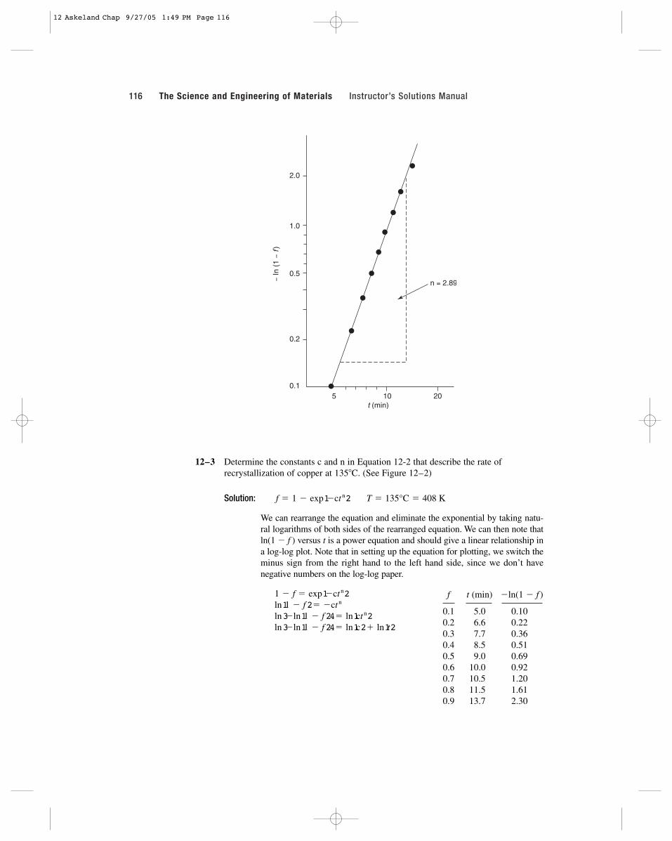
116 The Science and Engineering of Materials Instructor’s Solutions Manual
12–3 Determine the constants c and n in Equation 12-2 that describe the rate ofrecrystallization of copper at 135�C. (See Figure 12–2)
Solution:
We can rearrange the equation and eliminate the exponential by taking natu-ral logarithms of both sides of the rearranged equation. We can then note thatln(1 � f ) versus t is a power equation and should give a linear relationship ina log-log plot. Note that in setting up the equation for plotting, we switch theminus sign from the right hand to the left hand side, since we don’t havenegative numbers on the log-log paper.
ln3�ln11 � f 24� ln1c2� ln1t2ln3�ln11 � f 24� ln1ct
n2ln11 � f 2� �ct
n1 � f � exp1�ct
n2
T � 135°C � 408 Kf � 1 � exp1�ct n2
f t (min) �ln(1 � f )
0.1 5.0 0.100.2 6.6 0.220.3 7.7 0.360.4 8.5 0.510.5 9.0 0.690.6 10.0 0.920.7 10.5 1.200.8 11.5 1.610.9 13.7 2.30
5 10 20t (min)
0.1
0.2
0.5
1.0
2.0
− In
(1 −
f)n = 2.89
12 Askeland Chap 9/27/05 1:49 PM Page 116

12–4 Determine the activation energy for crystallization of polypropylene, using thecurves in Figure 12–30.
Solution: We can determine how the rate (equal to 1�t) changes with temperature:
1�1150 � 2732� 2.36 � 10�31�1316 min2160 s/min2� 5.27 � 10�51�1140 � 2732� 2.42 � 10�31�155 min2160 s/min2� 3.03 � 10�41�1130 � 2732� 2.48 � 10�31�19 min2160 s/min2� 1.85 � 10�3
1�T 1K�121�t 1s�12
rate � 1�t � c exp1�Q�RT2
CHAPTER 12 Dispersion Strengthening by Phase Transformations and Heat Treatment 117
A log-log plot of “�ln(1 � f )” versus “t” is shown. From the graph, we findthat the slope n � 3.1 and the constant c can be found from one of the pointsfrom the curve:
if f � 0.6, then t � 10. Then
c � 7.28 � 10�4. 1 � 0.6 � exp3�c11023.14
30 50 100t (min)
0.1
0.2
0.5
1.0
2.0
4.0
− In
(1 −
f)
n = 2.89
12 Askeland Chap 9/27/05 1:49 PM Page 117
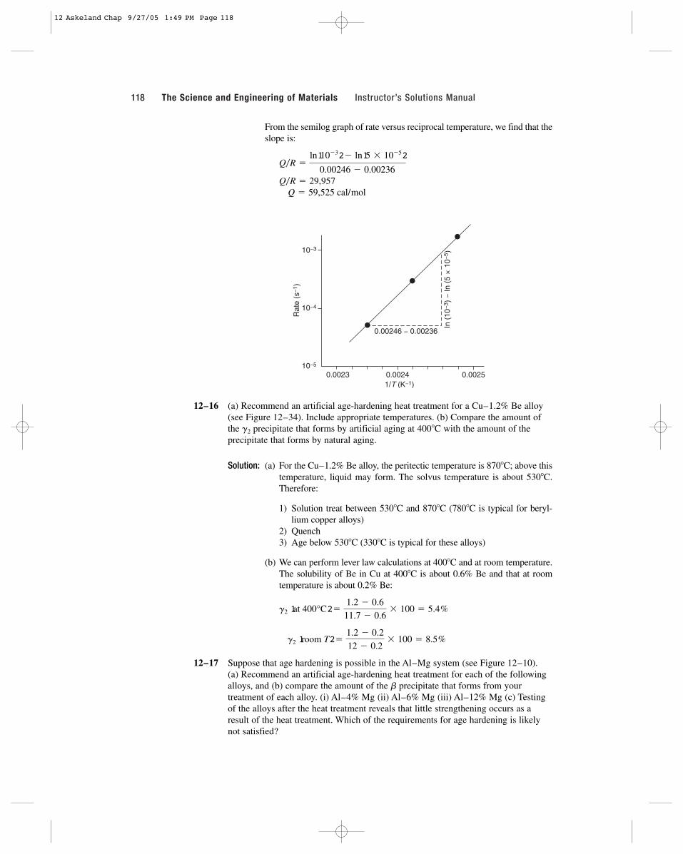
118 The Science and Engineering of Materials Instructor’s Solutions Manual
From the semilog graph of rate versus reciprocal temperature, we find that theslope is:
Q � 59,525 cal/mol Q�R � 29,957
Q�R �ln110�32� ln15 � 10�52
0.00246 � 0.00236
12–16 (a) Recommend an artificial age-hardening heat treatment for a Cu–1.2% Be alloy(see Figure 12–34). Include appropriate temperatures. (b) Compare the amount ofthe g2 precipitate that forms by artificial aging at 400�C with the amount of theprecipitate that forms by natural aging.
Solution: (a) For the Cu–1.2% Be alloy, the peritectic temperature is 870�C; above thistemperature, liquid may form. The solvus temperature is about 530�C.Therefore:
1) Solution treat between 530�C and 870�C (780�C is typical for beryl-lium copper alloys)
2) Quench3) Age below 530�C (330�C is typical for these alloys)
(b) We can perform lever law calculations at 400�C and at room temperature.The solubility of Be in Cu at 400�C is about 0.6% Be and that at roomtemperature is about 0.2% Be:
12–17 Suppose that age hardening is possible in the Al–Mg system (see Figure 12–10). (a) Recommend an artificial age-hardening heat treatment for each of the followingalloys, and (b) compare the amount of the b precipitate that forms from yourtreatment of each alloy. (i) Al–4% Mg (ii) Al–6% Mg (iii) Al–12% Mg (c) Testingof the alloys after the heat treatment reveals that little strengthening occurs as aresult of the heat treatment. Which of the requirements for age hardening is likelynot satisfied?
g2 1room T2�1.2 � 0.2
12 � 0.2� 100 � 8.5%
g2 1at 400°C2�1.2 � 0.6
11.7 � 0.6� 100 � 5.4%
10−5
10−4
10−3
0.0023 0.0024 0.0025
Rat
e (s
−1)
1/T (K−1)
0.00246 − 0.00236
In (
10−3
) −
In (
5 ×
10−
5 )
12 Askeland Chap 9/27/05 1:49 PM Page 118
Solution: (a) The heat treatments for each alloy might be:
Al–4% Mg Al–6% Mg Al–12% Mg
TEutectic � 451�C 451�C 451�CTSolvus � 210�C 280�C 390�C
SolutionTreat at: 210–451�C 280–451�C 390–451�C
Quench Quench Quench
Age at: �210�C �280�C �390�C
(b) Answers will vary depending on aging temperature selected. If all threeare aged at 200�C, as an example, the tie line goes from about 3.8 to35% Mg:
(c) Most likely, a coherent precipitate is not formed; simple dispersionstrengthening, rather than age hardening, occurs.
12–18 An Al–2.5% Cu alloy is solution-treated, quenched, and overaged at 230�C toproduce a stable microstructure. If the spheroidal u precipitates so that form has adiameter of 9000 Å and a density of 4.26 g/cm3, determine the number of precipitateparticles per cm3.
Solution:
12–33 Figure 12–31 shows a hypothetical phase diagram. Determine whether each of thefollowing alloys might be good candidates for age hardening and explain youranswer. For those alloys that might be good candidates, describe the heat treatmentrequired, including recommended temperatures.
(a) A–10% B (b) A–20% B (c) A–55% B(d) A–87% B (e) A–95% B
Solution: (a) A–10% B is a good candidate: Solution Treatment @ T � 290 to 400�CQuenchAge @ T � 290�C
(b) A–20% B: Some age hardening effect may occur when alloy is solutiontreated below 400�C and quenched. However, eutectic is also present andthe strengthening effect will not be as dramatic as in (a).
# of particles �0.0182 cm3
382 � 10�15 cm3 � 4.76 � 1010 particles
Vu � 14p�3214.5 � 10�5 cm23 � 382 � 10�15 cm3
du � 9000 � 10�10 m � 9 � 10�5 cm ru � 4.5 � 10�5 cm
vol fraction u �2.88 g�4.26 g/cm3
2.88�4.26 � 97.12�2.669� 0.0182 cm3 u�cm3 alloy
wt% a �53 � 2.5
53 � 1� 97.12% wt% u � 2.88%
Al–12% Mg: %b � 112 � 3.82�135 � 3.82� 100 � 26.8%
Al–6% Mg: %b � 16 � 3.82�135 � 3.82� 100 � 7.1%
Al–4% Mg: %b � 14 � 3.82�135 � 3.82� 100 � 0.6%
CHAPTER 12 Dispersion Strengthening by Phase Transformations and Heat Treatment 119
%
%
%
12 Askeland Chap 9/27/05 1:49 PM Page 119
120 The Science and Engineering of Materials Instructor’s Solutions Manual
(c) A–55% B: almost all u is formed. The alloy is expected to be very brittle.
(d) A–87% B: the alloy cools from a two-phase (b� u) region to a one-phase(b) region, opposite of what we need for age hardening.
(e) A–95% B: the alloy is single phase (b) at all temperatures and thus cannotbe age hardened.
12–46 For an Fe–0.35%C alloy, determine (a) the temperature at which austenite firstbegins to transform on cooling, (b) the primary microconstituent that forms, (c) thecomposition and amount of each phase present at 728�C, (d) the composition andamount of each phase present at 726�C, and (e) the composition and amount of eachmicroconstituent present at 726�C.
Solution: (a) 795�C (b) primary a-ferrite
(c)
(d)
(e) primary a: 0.0218% C % primary a � 56.1%pearlite: 0.77% C % Pearlite � 43.9%
12–47 For an Fe–1.15%C alloy, determine (a) the temperature at which austenite firstbegins to transform on cooling, (b) the primary microconstituent that forms, (c) thecomposition and amount of each phase present at 728�C, (d) the composition andamount of each phase present at 726�C, and (e) the composition and amount of eachmicroconstituent present at 726�C.
Solution: (a) 880�C (b) primary Fe3C
(c)
(d)
(e) primary Fe3C: 6.67% C % primary Fe3C � 6.4%pearlite: 0.77% C % Pearlite � 93.6%
12–48 A steel contains 8% cementite and 92% ferrite at room temperature. Estimate thecarbon content of the steel. Is the steel hypoeutectoid or hypereutectoid?
Solution: a � 0.92 �6.67 � x
6.67 � 0 x � 0.53% C, ∴ Hypoeutectoid
Fe3C: 6.67% C %Fe3C � 17%
a: 0.0218% C %a �6.67 � 1.15
6.67 � 0.0218� 100 � 83%
g: 0.77% C %g � 93.6%
Fe3C: 6.67% C %Fe3C �1.15 � 0.77
6.67 � 0.77� 100 � 6.4%
Fe3C: 6.67% C %Fe3C � 4.9%
a: 0.0218% C %a �6.67 � 0.35
6.67 � 0.0218� 100 � 95.1%
g: 0.77% C %g � 43.9%
a: 0.0218% C %a �0.77 � 0.35
0.77 � 0.0218� 100 � 56.1%%
%
%
%
%
%
%
%
12 Askeland Chap 9/27/05 1:49 PM Page 120
12–49 A steel contains 18% cementite and 82% ferrite at room temperature. Estimate thecarbon content of the steel. Is the steel hypoeutectoid or hypereutectoid?
Solution:
12–50 A steel contains 18% pearlite and 82% primary ferrite at room temperature. Estimatethe carbon content of the steel. Is the steel hypoeutectoid or hypereutectoid?
Solution:
12–51 A steel contains 94% pearlite and 6% primary cementite at room temperature.Estimate the carbon content of the steel. Is the steel hypoeutectoid or hypereutectoid?
Solution:
12–52 A steel contains 55% a and 45% g at 750�C. Estimate the carbon content of thesteel.
Solution: a � 0.02% C and g � 0.6% C (from the tie line at 750�C)
12–53 A steel contains 96% g and 4% Fe3C at 800�C. Estimate the carbon content of thesteel.
Solution: (from the tie line at 800�C)
12–54 A steel is heated until 40% austenite, with a carbon content of 0.5%, forms.Estimate the temperature and the overall carbon content of the steel.
Solution: In order for g to contain 0.5% C, the austenitizing temperature must beabout 760�C (from the tie line). At this temperature:
12–55 A steel is heated until 85% austenite, with a carbon content of 1.05%, forms.Estimate the temperature and the overall carbon content of the steel.
Solution: In order for � to contain 1.05% C, the austenitizing temperature must beabout 845�C (from the tie line). At this temperature:
0.85 �6.67 � x
6.67 � 1.05 x � 1.893% C
0.4 �x � 0.02
0.5 � 0.02 x � 0.212% C
g � 0.96 �6.67 � x
6.67 � 0.92 x � 1.15% C
g � 0.92% C and Fe3C � 6.67% C
%a � 55 �0.6 � x
0.6 � 0.02� 100 x � 0.281% C
Pearlite � 0.94 �6.67 � x
6.67 � 0.77, x � 1.124% C, ∴ Hypereutectoid
x � 0.156% C, ∴ Hypoeutectoid
primary a � 0.82 �0.77 � x
0.77 � 0.0218,
a � 0.82 �6.67 � x
6.67 � 0 x � 1.20% C, ∴ Hypereutectoid
CHAPTER 12 Dispersion Strengthening by Phase Transformations and Heat Treatment 121
12 Askeland Chap 9/27/05 1:49 PM Page 121
122 The Science and Engineering of Materials Instructor’s Solutions Manual
12–56 Determine the eutectoid temperature, the composition of each phase in the eutectoidreaction, and the amount of each phase present in the eutectoid microconstituent forthe following systems. For the metallic systems, comment on whether you expectthe eutectoid microconstituent to be ductile or brittle.
(a) ZrO2–CaO (See Figure 12–32)(b) Cu–Al at 11.8%Al (See Figure 12–33(c))(c) Cu–Zn at 47%Zn (See Figure 12–33(a))(d) Cu–Be (See Figure 12–33(d))
Solution: (a) @900�C: Tetragonal12% CaO S Monoclinic3% CaO � Cubic14% CaO
The eutectoid microconstituent (and the entire material, for that matter)will be brittle because the materials are ceramics
(b)
Most of the eutectoid microconstituent is a (solid solution strengthenedcopper) and is expected to be ductile.
(c)
Slightly more than half of the eutectoid is the copper solid solution; thereis a good chance that the eutectoid would be ductile.
(d)
Slightly more than half of the eutectoid is the copper solid solution; wemight then expect the eutectoid to be ductile.
12–58 Compare the interlamellar spacing and the yield strength when an eutectoid steel isisothermally transformed to pearlite at (a) 700�C, and (b) 600�C.
Solution: We can find the interlamellar spacing from Figure 12–19 and then use thisspacing to find the strength from Figure 12–18.
(a)
(b)
12–66 An isothermally transformed eutectoid steel is found to have a yield strength of410 MPa. Estimate (a) the transformation temperature and (b) the interlamellar spac-ing in the pearlite.
l � 1.5 � 10�5 cm 1�l � 66,667 YS � 460 MPa 167,600 psi2
l � 7.5 � 10�5 cm 1�l � 13,333 YS � 200 MPa 129,400 psi2
%a �11 � 6
11 � 1.5� 100 � 52.6% %b � 47.4%
@605°C: g1 6% Be S a1.5% Be � g2 11% Be
%a �59 � 47
59 � 36� 100 � 52.2% %g � 47.8%
@250°C: b¿47% Zn S a36% An � g59% Zn
%a �15.6 � 11.8
15.6 � 9.4� 100 � 61.3% %b � 38.7%
@565°C: b11.8% Al S a9.4% Al � g2 15.6% Al
%Monoclinic �14 � 12
14 � 3� 100 � 18% %Cubic � 82%%
%
%
%
%
%
%
%
12 Askeland Chap 9/27/05 1:49 PM Page 122

Solution: We can first find the interlamellar spacing from Figure 12–18; then usingthis interlamellar spacing, we can find the transformation temperaturefrom Figure 12–19.
(a) transformation temperature � 615�C
(b)
12–67 Determine the required transformation temperature and microconstituent if an eutec-toid steel is to have the following hardness values:
(a) HRC 38 (b) HRC 42 (c) HRC 48 (d) HRC 52
Solution: (a) 600�C (b) 400�C (c) 340�C (d) 300�Cpearlite bainite bainite bainite
12–68 Describe the hardness and microstructure in an eutectoid steel that has been heatedto 800�C for 1 h, quenched to 350�C and held for 750 s, and finally quenched toroom temperature.
Solution: HRC � 47 and the microstructure is all bainite.
12–69 Describe the hardness and microstructure in an eutectoid steel that has been heatedto 800�C, quenched to 650�C and held for 500 s, and finally quenched to roomtemperature.
Solution: HRC � 25 and the microstructure is all pearlite.
12–70 Describe the hardness and microstructure in an eutectoid steel that has been heatedto 800�C, quenched to 300�C and held for 10 s, and finally quenched to roomtemperature.
Solution: HRC � 66 and the microstructure is all martensite.
12–71 Describe the hardness and microstructure in an eutectoid steel that has been heatedto 800�C, quenched to 300�C and held for 10 s, quenched to room temperature, andthen reheated to 400�C before finally cooling to room temperature again.
Solution: HRC � 42 and the microstructure is all tempered martensite.
12–72 A steel containing 0.3% C is heated to various temperatures above the eutectoidtemperature, held for 1 h, and then quenched to room temperature. Using Figure 12–34, determine the amount, composition, and hardness of any martensite that forms when the heating temperature is
(a) 728�C (b) 750�C (c) 790�C (d) 850�C
Solution: (a)
(b) g: 0.60% C %M �0.3 � 0.02
0.6 � 0.02� 100% � 48.3% HRC 65
g: 0.77% C %M �0.3 � 0.0218
0.77 � 0.0218� 100% � 37.2% HRC 65
1�l � 60,000 or l � 1.67 � 10�5 cm
CHAPTER 12 Dispersion Strengthening by Phase Transformations and Heat Treatment 123
%
%
12 Askeland Chap 9/27/05 1:49 PM Page 123
124 The Science and Engineering of Materials Instructor’s Solutions Manual
(c)
(d)
12–80 A steel containing 0.95% C is heated to various temperatures above the eutectoidtemperature, held for 1 h, and then quenched to room temperature. Using Figure 12–34, determine the amount and composition of any martensite that forms when the heating temperature is
(a) 728�C (b) 750�C (c) 780�C (d) 850�C
Solution: (a)
(b)
(c)
(d)
12–81 A steel microstructure contains 75% martensite and 25% ferrite; the composition ofthe martensite is 0.6% C. Using Figure 12–34, determine (a) the temperature fromwhich the steel was quenched and (b) the carbon content of the steel.
Solution: In order for g (and therefore martensite) to contain 0.6% C, the austeni-tizing T � 750�C. Then:
12–82 A steel microstructure contains 92% martensite and 8% Fe3C; the composition ofthe martensite is 1.10% C. Using Figure 12–34, determine (a) the temperature fromwhich the steel was quenched and (b) the carbon content of the steel.
Solution: In order for g (and therefore martensite) to contain 1.10% C, the austeni-tizing T � 865�C. Then:
12–83 A steel containing 0.8% C is quenched to produce all martensite. Estimate the vol-ume change that occurs, assuming that the lattice parameter of the austenite is 3.6 Å.Does the steel expand or contract during quenching?
Solution:
VM � a2c � 12.85 � 10�8 cm22 12.96 � 10�82� 24.0426 � 10�24 cm3
Vg � 13.6 Å23 � 46.656 � 10�24 cm3
M � g � 0.92 �6.67 � x
6.67 � 1.10 x � 1.55% C
M � g � 0.25 �0.6 � x
0.6 � 0.02 x � 0.455% C
g � 0.95% C %M � 100% HRC 65
g � 0.88% C %M �6.67 � 0.95
6.67 � 0.88� 100% � 98.8% HRC 65
g � 0.82% C %M �6.67 � 0.95
6.67 � 0.82� 100% � 97.8% HRC 65
g � 0.77% C %M �6.67 � 0.95
6.67 � 0.77� 100% � 96.9% HRC 65
g: 0.3% C %M � 100% HRC 55
g: 0.35% C %M �0.3 � 0.02
0.35 � 0.02� 100% � 84.8% HRC 58%
%
%
%
%
%
12 Askeland Chap 9/27/05 1:49 PM Page 124
But to assure that we have the same number of atoms, we need to considertwo unit cells of martensite (2 atoms/cell) for each cell of FCC austenite(4 atoms/cell)
12–84 Describe the complete heat treatment required to produce a quenched and temperedeutectoid steel having a tensile strength of at least 125,000 psi. Include appropriatetemperatures.
Solution: Austenitize at approximately 750�C,Quench to below 130�C (the Mf temperature)Temper at 620�C or less.
12–85 Describe the complete heat treatment required to produce a quenched and temperedeutectoid steel having a HRC hardness of less than 50. Include appropriatetemperatures.
Solution: Austenitize at approximately 750�C,Quench to below the Mf (less than 130�C)Temper at a temperature higher than 330�C, but less than 727�C.
12–86 In eutectic alloys, the eutectic microconstituent is generally the continuous one, butin the eutectoid structures, the primary microconstituent is normally continuous. Bydescribing the changes that occur with decreasing temperature in each reaction,explain why this difference is expected.
Solution: In a eutectoid reaction, the original grain boundaries serve as nucleationsites; consequently the primary microconstituent outlines the originalgrain boundaries and isolates the eutectoid product as a discontinuousconstitutent.
In a eutectic reaction, the primary phase nucleates from the liquid andgrows. When the liquid composition approaches the eutectic composition,the eutectic constituent forms around the primary constituent, making theeutectic product the continuous constitutent.
%¢V � c122124.04262� 46.656
46.656d� 100% � 3.06%, ∴ expansion
CHAPTER 12 Dispersion Strengthening by Phase Transformations and Heat Treatment 125
12 Askeland Chap 9/27/05 1:49 PM Page 125

12 Askeland Chap 9/27/05 1:49 PM Page 126